wind and seismic time history analysis for lattice …
TRANSCRIPT
International Journal of Advances in Engineering & Technology, May 2013.
©IJAET ISSN: 2231-1963
826 Vol. 6, Issue 2, pp. 826-835
WIND AND SEISMIC TIME HISTORY ANALYSIS FOR LATTICE
SHELL TUBE RCC FRAMED BUILDINGS
Jayesh. A. Dalal1, Atul. K. Desai2
1M.Tech Research scholar at Applied Mechanics Department,
Sardar Vallabhbhai National Institute of Technology, Surat, India. 2Professor at Applied Mechanics Department,
Sardar Vallabhbhai National Institute of Technology, Surat, India.
ABSTRACT
Latticed shell tube – RC core walls are new structural systems, with RC core walls in center and latticed shell
tubing system on the outside. The shear rigidity of RC core wall is larger for lateral wind forces are the external
latticed shell tube are more useful. The combination of these two system can achieve a powerful lateral forces
resisting system. With above point of view, the model with different bracing systems such as X, Inverted V, and V
with different numbers of stories are prepared in ETABS 9.7.1 software. For earthquake Time History Analysis
were applied. Analytical results are compared to achieve the most suitable resisting system against the lateral
forces.
KEYWORDS: Latticed shell tube, Shear wall, wind and seismic analysis, Analysis, multistoried Building
I. INTRODUCTION
The aftermath of an earthquake manifests great devastation due to unpredicted seismic motion striking
extensive damage to innumerable buildings of varying degree, i.e. either full or partial. This damage
to structures in turn causes irreparable loss of life with a large number of casualties.
Structures are designed to resist moderate and frequently occurring earthquakes must have sufficient
stiffness and strength to control deflection and to prevent any possible damage. However, it is
inappropriate to design a structure to remain in the elastic region, under severe earthquakes, because
of the economic constraints. The inherent damping of yielding structural elements can advantageously
be utilized to lower the strength requirement, leading to a more economical design. This yielding
usually provides the ductility or toughness of the structure against the sudden brittle type structural
failure.
A building must have a complete structural system capable of carrying all gravity loads to its
foundation in life span of building. While dealing with lateral forces, there is a natural trend to
manage these forces with same methods used for gravity loads. Conventionally designed columns of a
structure cannot carry the weight of the building and tolerate the large sideways movement caused by
the motions of earthquake and/or wind. Earthquake and wind gusts are idealized as equivalent static
load of certain magnitude that must be resisted by the structure.
This study examines the lattice shell tube structure in the modeling of earthquake and wind flow
around tall buildings of cross sectional shape, but same cross sectional area, consequently predicting
the response of the structures under generated wind loads. It focuses on analysis of tall structures
under static earthquake and static wind loading. ETABS 9.7.1 software has been used to analysis of
the models for this study. This lattice shell tube can be used for retrofitting of old R.C.C. frame
structure. [1]
In this paper effort have been made to solve circular, square and octagonal different shape of building
with V, Inverted V and X type of bracing.
International Journal of Advances in Engineering & Technology, May 2013.
©IJAET ISSN: 2231-1963
827 Vol. 6, Issue 2, pp. 826-835
II. LITERATURE REVIEW
Latticed shell tube–RC core walls are a new structural system with RC core walls in the center and
latticed shell tubing on the outsides. The shear rigidity of RC core wall is big, and the resisting
overthrow capability of external latticed shell tubes is powerful. This combination can reduce
structural damage that could be caused by seismic, and it remarkably enhances the anti-seismic
capability of structures. The basic design procedure for constructing these structures is introduced
sequentially, particularly pointing out the key problem of the design. A comprehensive structural
analysis is carried out and the performance of the new structure is evaluated thoroughly. [5]
The purpose of this study is to model and analyze the non-planar shear wall assemblies of shear wall-
frame structures. Two three dimensional models, for open and closed section shear wall assemblies,
are developed. These models are based on conventional wide column analogy, in which a planar shear
wall is replaced by an idealized frame structure consisting of a column and rigid beams located at
floor levels. The rigid diaphragm floor assumption, which is widely used in the analysis of multi-
storey building structures, is also taken into consideration. The connections of the rigid beams are
released against torsion in the model proposed for open section shear walls. For modelling closed
section shear walls, in addition to this the torsional stiffness of the wide columns are adjusted by using
a series of equations. Several shear wall-frame systems having different shapes of non-planar shear
wall assemblies are analyzed by static lateral load, response spectrum and time history methods where
the proposed methods are used. The results of these analyses are compared with the results obtained
by using common shear wall modelling techniques. [9]
A coupled shear wall system consisting of steel fill plates bounded with the column-beam system
resembles a cantilever plate girder where the plate, columns and beams of the system act as the web,
flanges and stiffeners of the girder, respectively.[13]
III. DIFFERENT LATERAL LOAD RESISTING SYSTEMS FOR MULTI-STOREY
BUILDINGS
When designing a building that will be capable of withstanding an earthquake, engineers can choose
various structural components, the earthquake resistance of which is now well understood, and then
combine then into what is known as complete lateral load resisting system.
There are three structural systems defined by UBC code: bearing wall systems, building frame
systems and moment resisting frames systems.
Bearing wall systems consist of walls carrying vertical load, and located along exterior lines and
interior locations if necessary. Many of these bearing walls are also used to resist lateral forces and
hence called shear walls. Bearing wall system do not contain complete vertical load carrying space
frames but, may use some columns to support floor and roof loads. Examples of this system are
wooden frame buildings, concrete tilt up buildings and masonry wall buildings.
Building frame systems use a complete three dimensional space frame to support vertical loads, but
use either shear wall or braced frames to resist lateral forces. This system includes steel and/or
concrete frames along the perimeter and throughout the interior frame supporting vertical.
Moment resisting frames consist of beam column members in plane with rigid or semi-rigid joints.
The strength and stiffness of a frame is proportional to member’s sizes, and inversely proportional to
the columns unsupported height and spacing. A moment resisting frame produces significant bending
moments at beam column joint, with inflection points at mid points of beam and columns. The space
frame throughout the building carries vertical loads and uses frame elements to resist lateral forces.
IV. TYPES OF BRACING SYSTEM
The bracing systems used today are of following type
1. Single diagonal bracing
2. Double diagonal or X-bracing
3. K-bracing, either vertical or horizontal
4. Eccentric bracing
5. Chevron or V-bracing

International Journal of Advances in Engineering & Technology, May 2013.
©IJAET ISSN: 2231-1963
828 Vol. 6, Issue 2, pp. 826-835
Currently, there are four typical types of bracing that are used in practice. These include: X-bracing,
Inverted V-bracing, eccentric bracing, and single-diagonal bracing. Each of these different types of
bracing provides different levels of strength to the building as well as different levels of interference
between floors. Furthermore, each of these types of braces can be used between one bay or between
multiple bays. Thus, there are numerous ways in which to brace a building each of which has a
different effect on the associated lateral drift. Drift and P-∆ effect are important for tall building. [3]
[4]
X-bracing or cross bracing, arguably the most common method for bracing a structure, uses two full
length members to connect to the four beam-column joints in a bay. The advantage of this type of
bracing is in the size of the members. As the members are considered to be only stressed in tension, it
is assumed that only one member is stressed at a time. Furthermore, the use of the member in tension
only, results in the smallest member sizes possible. [6]
Figure 1 - Single Diagonal bracing system and X Bracing System
The Inverted V-bracing method is also a very common way to effectively brace a structure from
horizontal loads. This method requires two members at the bottom of which are connected to the
beam column joints as in the cross bracing method. [10] [11]
Figure 2 – X bracing system and Inverted V Bracing System [2]
The top of the two members, however are connected with a gusset plate at the center of the
member above. The advantage of this method comes more so from an architectural perspective than a
structural benefit. Inverted V-bracing, as opposed to cross bracing, allows for the architect to place
doorways and corridors through a buildings bracing line. From a structural point of view tying the
Inverted V-bracing into the middle of the span of the floor above allows for the beam or girder to be
analyzed as a two span continuous beam, therefore allowing for that particular member to be reduced
in size. The disadvantage comes with the fact that both members are considered to be working at all
times in both compression and tension unlike the cross bracing technique. [12]
V. MODELING
The computer software used for this study was the program ETAB 9.7.1. This particular software was
selected for a number of different reasons. Perhaps the biggest reason for its use was simply its
availability in the research laboratory. Additionally, it is a software different from that used in other
studies conducted, thus helping to make this research different. With the ETAB 9.7.1 program, there
are many key features that make its use in this study lucrative. ETAB 9.7.1 is a simple yet powerful
tool that is more than capable of producing the results required for this specific research. For slab
modeling FEM boundaries are considered. [7] [8]

International Journal of Advances in Engineering & Technology, May 2013.
©IJAET ISSN: 2231-1963
829 Vol. 6, Issue 2, pp. 826-835
The lateral loads to be applied on the buildings are based on the Indian standards. The study is
performed for building in Surat. Seismic zone III as per IS 1893:2002. The frames are assumed to be
firmly fixed at the bottom and the soil–structure interaction is neglected. The mathematical models of
building ranging from Ground+40 to Ground+100 stories at an interval of 10 stories are prepared with
4 bays in X-direction and 4 bays in Y-direction. The frame has bay width of 10 m and storey height of
3.36 as shown in Figure 3.
These models are further analyzes by using three types of bracing types viz. Double diagonal or X-
bracing (X), Inverted-V bracing or Chevron bracing (Inv.V) and V-bracing Frame exhibits tall
building behavior under lateral loads assuming that design is governed by lateral stiffness criteria
rather than by member strength requirement. A typically uniformly live load is taken from I.S-875-
(Part-II) as 4 KN/m2.
Design optimization process, the structure is first analyzed with members taken to have their
minimum limiting sizes for both columns and beams. Such an original design tends to be too flexible
in terms of lateral stiffness requirements. The typical allowable inter story drift ratio of 1/500 and the
overall top displacement limit of H/500, where H denotes the height of the building, are adopted in the
analysis and design process. In following table Column C1 to Column C12 in shown Figure 3. Table 1 - Member sizes of element
Column Description Grade Size
C1 TO C12 M40 1.7 X 1.7
Bracing Member (Lattice Cell Tube) Diameter 200 mm Thickness 20 mm
Wind loading is calculated as per IS-875:1984 part-3. Basic wind speed is applicable to 10 m height
above mean ground level for different zones of the country. Basic wind speed is based on peak gust
velocity averaged over a short time interval of about 3 seconds and corresponds to mean heights
above ground level in an open terrain (category 1). Basic wind speed is worked out for a 50 year
return period. The basic wind speed (Vb) for Surat is 44 m/s and is modified to include the following
effect to get design wind velocity at any height (Vz).,
Design wind speed at height, z can be mathematically expressed as follows:
Vz = Vb x K1 x K2 x K3
Where
Vb = 44 m/s, basic wind speed for Surat city
K1 = 1, Probability factor
K2 = 1, Terrain, Height and Structure size factor for category 1
K3= 1, Topography Factor for slope < 3 degree
The design wind pressure, Pz at any height above mean ground level shall be obtained by the
following relationship between wind pressure and wind velocity Pz= 0.6 Vz2 (N/mm2). The coefficient
0.6 in the above formula depends on a number of factors and mainly on the atmospheric pressure and
air temperature. The value chosen corresponds to the average appropriate Indian atmospheric
conditions. Table 2 - Model data of building
Building location Surat
Storey height 3.36 m
Seismic Zone III
Dead load 2 KN/m2
Imposed Load(Live load) 4 KN/m2
Earthquake load As per IS:1893 (Part-1) 2002
Wind load As per IS:875 (Part-3) 1987 R 1997
Slab thickness 150 mm
Seismic Zone factor 0.16
Importance factor as per code 1
Response reduction factor as per code 5
Critical damping as per code 5%

International Journal of Advances in Engineering & Technology, May 2013.
©IJAET ISSN: 2231-1963
830 Vol. 6, Issue 2, pp. 826-835
Figure 3 – Plan of the building
Figure 4 – G + 50 storey model with triple layer V bracing
VI. TIME HISTORY ANALYSIS
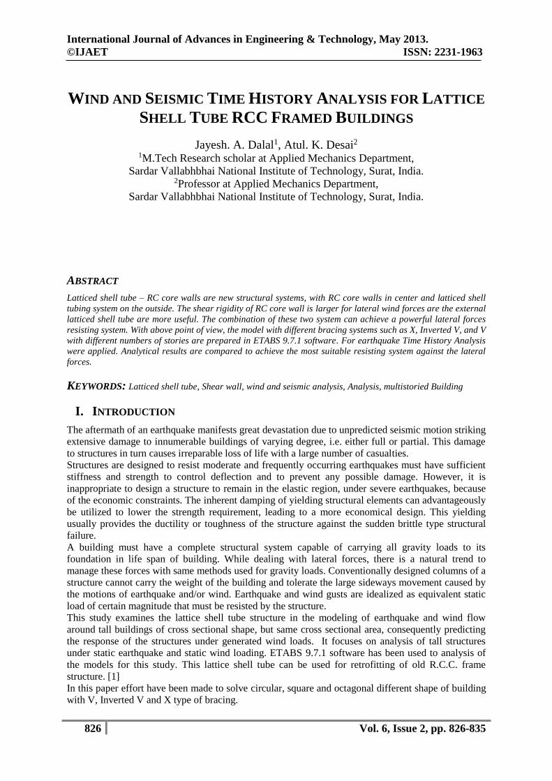
Time History excitation is carried out for Bhuj earthquake on Ground + 40 to Ground + 100 story
with IN V, V and X-bracing building along with Time history-X and Time history-Y time history
functions.
International Journal of Advances in Engineering & Technology, May 2013.
©IJAET ISSN: 2231-1963
831 Vol. 6, Issue 2, pp. 826-835
Figure 5 – Input data of Bhuj for Time History Analysis
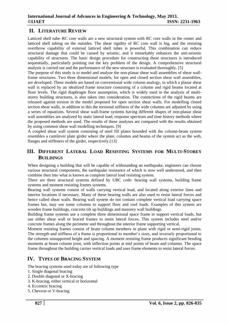
VII. DIFFERENT BRACING CONFIGURATION
Throughout the study different bracing configurations were analyzed using three different types of
bracings. These types of bracings include V-bracing, X-bracing, and Inverted V-bracing (V-bracing).
To start the parametric analysis the most well-known and highly used approaches to effectively brace
a building were modeled first. These include: bracing the center bay only, bracing the exterior bays
only, upon analyzing these layouts, more specific differences were looked at including: different
orientations of members, adding additional bracing at problem areas of the structure, bracing through
multiple floors i.e. mega bracing.
Few models are shown with different bracing configurations for various heights of the buildings i.e.
for Ground+50 story.
Figure 6 – Sectional elevation Ground+50 story model with double layer Inverted V, V and X bracing on
ETABS

International Journal of Advances in Engineering & Technology, May 2013.
©IJAET ISSN: 2231-1963
832 Vol. 6, Issue 2, pp. 826-835
Figure 7 – Sectional elevation Ground+50 story model with triple layer Inverted V, V and X bracing on ETABS
VIII. DIFFERENT SHAPE OF THE BUILDING
Throughout the study different shape of the building were analyzed using three different types of
shape of the buildings. These Shape of the buildings include Square, Octagonal & Circular. To start
the parametric analysis the most well-known and highly used approaches to effectively shape of the
building were modeled first.
Few models are shown with different shape of the building for various heights of the buildings i.e. for
Ground+40 Story to Ground+100 Story.
Figure 8 – Plan Ground+50 story model on ETABS
International Journal of Advances in Engineering & Technology, May 2013.
©IJAET ISSN: 2231-1963
833 Vol. 6, Issue 2, pp. 826-835
Figure 9 – Latticed shell tube structure
IX. RESULTS AND DISCUSSIONS
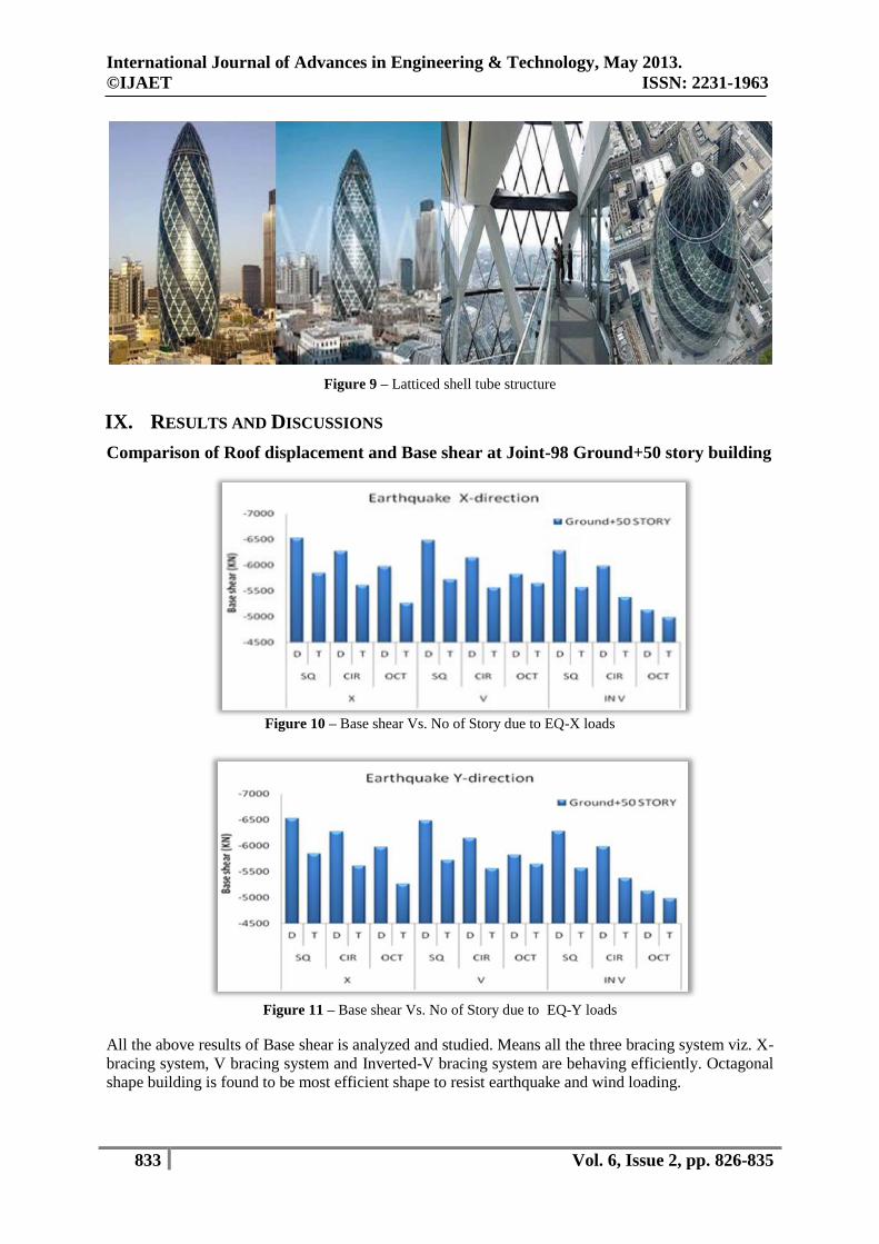
Comparison of Roof displacement and Base shear at Joint-98 Ground+50 story building
Figure 10 – Base shear Vs. No of Story due to EQ-X loads
Figure 11 – Base shear Vs. No of Story due to EQ-Y loads
All the above results of Base shear is analyzed and studied. Means all the three bracing system viz. X-
bracing system, V bracing system and Inverted-V bracing system are behaving efficiently. Octagonal
shape building is found to be most efficient shape to resist earthquake and wind loading.

International Journal of Advances in Engineering & Technology, May 2013.
©IJAET ISSN: 2231-1963
834 Vol. 6, Issue 2, pp. 826-835
Figure 12 – Roof displacement Vs. No of Story due to WIND-X loads
Figure 13 – Roof displacement Vs. No of Story due to WIND-Y loads
All the above results of Roof displacement is analyzed and studied. It is found that results are coming
within IS limit. Means all the three bracing system viz. X-bracing system, V bracing system and
Inverted-V bracing system are behaving efficiently.
Amongst the all bracing system Inverted–V bracing system shows significant reduction in roof
displacement and time period values. Roof displacement is satisfied the H/500 criteria in case of wind
in X –direction and Y-direction.
X. CONCLUSIONS
In this study performance of bracing configuration and suitability in different types of building is
checked. Different models have been modeled at the interval of 10 starting from Ground + 40 stories
to Ground + 100 stories. Their performance is analyzed using three bracing system which are in
practice now a day's viz. X-bracing, V–bracing and Inverted V-bracing system subjected to
earthquake and wind loading. To check the performance of these different building models time
period, maximum roof displacement and base shear in the column are evaluated and analyzed and
drawn the conclusion as under:
Inverted V-bracing is found to be most efficient bracing type than X-bracing and V bracing
type. Effective reduction in roof displacement is achieved using Inverted V-bracing.
Lateral load resisting system using bracing provided at multiple bay will be efficient for high-
rise buildings.
Octagonal shape building is found to be most efficient shape than square shape and circular
shape building to resist earthquake and wind loading.
D - Double layer bracing, T - Triple layer bracing

International Journal of Advances in Engineering & Technology, May 2013.
©IJAET ISSN: 2231-1963
835 Vol. 6, Issue 2, pp. 826-835
Triple layer mega bracing is most efficient than double layer mega bracing due to earthquake
and wind loading.
XI. FUTURE WORK
The study carried out in this thesis can be extended further with the following scope of work
1) Use of eccentric bracing can be done enhance the performance of the building.
2) Use combination of bracing types in a single building can be done and performance will be
checked.
3) Bracing with the dampers can be used.
4) Use different bracing can be done enhance the performance of the combination building +
microwave tower.
REFERENCES
1) Ghobarah, H. AbouElfath.(2001),”Rehabilitation of a reinforced concrete frame using eccentric steel
bracing”, Engineering Structures, 23, 745–755.
2) Abdolreza Zare.(2003),“Use of steel bracing in reinforced concrete frames”, Engineering Structures,
19, 1018-1024.
3) Bhowmick Anjan K., GilbertT. Grondin, RobertG. Driver.(2009),”Seismic Analysis of steel plate shear
wall considering strain rate and P delta effects”, Journal of Constructional Steel research, 65, 1149-
1159.
4) G. Ravi Kumar, S.R. Satish Kumar, V. Kalyanaraman.(2007),”Behaviour of frames with Non Buckling
bracings under earthquake loading”, Journal of Constructional Steel research, 63, 254–262.
5) Gong Jinghai, Liang XinhuaH.(2007),“Design method research into latticed shell tube–reinforced
concrete (RC) core wall structures”, Journal of Constructional Steel research, 63, 949-960.
6) Mahmoud R. Maheri , R. Akbari.(2003),”Seismic behavior factor, R, for steel X-braced and knee
Braced RC buildings”, Engineering Structures, 25, 1505–1513.
7) Rashed Y.F.(2000),“Analysis of building shear wall using boundary elements” Engineering analysis
with boundary elements, 24, 287-293.
8) Swaddiwudhipomg S., Y.B.Lim and S.L. Lee.(1988),”An efficient finite stripe analysis of frame shear
wall tall building“, Computer and Structure, 29, 1111-1118.
9) Tolga Akis.(2006),“Lateral load analysis of shear wall-frame structures,” Journal of Structural
Engineering, 116, 540-548.
10) Wallace john W. and Orakcal Kutay,(2002),” ACI 318-99 provisions for seismic Design of Structural
walls”, The Structural journal, July-August 2002, 499-508.
11) Wan-shin Park, Hyun-Do Yun.(2005), “Seismic behavior of steel coupling beams linking reinforced
concrete shear walls”, Engineering structures, 27, 1024-1039.
12) Wen Z.P., Y.X. Hu, K.T. chun. (2002), ” Site effect on vulnerability of high – rise shear wall building
under near and far field earthquakes”, Soil dynamics and earthquakes engineering, 22, 1175-1182.
13) Abdollahzadeh. G., Malekzadeh. H. (2013), “Response Modification Factor of Coupled Steel Shear
Walls”, Civil Engineering Infrastructures, 1(1), 15-26.
AUTHORS
Jayesh A dalal was born in Surat, Gujarat, India, received B.E in Civil Engineering from
Regional Engineering Collage of Surat, Gujarat, India and M.Tech (Research) in Civil
Engineering (Structural Engineering) from Sardar Vallabhbhai National Institute of
Technology, Surat, Gujarat, India. He is currently working as project consultant in Surat,
Gujarat, India.
Atul K Desai was born in Surat, Gujarat, India, received B.E in Civil Engineering and M.E in
Civil Engineering (Structural Engineering) from Regional Engineering Collage of Surat,
Gujarat, India and Ph.D. in Civil Engineering (Structural Engineering) from Sardar
Vallabhbhai National Institute of Technology, Surat, Gujarat, India. He is currently working as
professor in applied mechanics department in Sardar Vallbhbhai National Institute of
Technology in Surat, Gujarat, India.