wind analysis and design of g+5 residential building using
TRANSCRIPT

International Journal of Innovative Research in Science, Engineering and Technology (IJIRSET)
| e-ISSN: 2319-8753, p-ISSN: 2320-6710| www.ijirset.com | Impact Factor: 7.512|
|| Volume 9, Issue 7, July 2020 ||
IJIRSET © 2020 | An ISO 9001:2008 Certified Journal | 5687
Wind Analysis and Design of G+5 Residential
Building Using STAAD.Pro
Vinay K V 1, Kavya N 2, Praveen Yadav B 2, Gowtham M 2, Raghavendra N 2
Assistant Professor, Department of Civil Engineering, NDRK Institute of Technology, Hassan, Karnataka, India1
UG Student, Department of Civil Engineering, NDRK Institute of Technology, Hassan, Karnataka, India2
ABSTRACT: This study presents a comparative study of wind loads to decide the design loads of a G+5 building. The
significance of this examination is to estimate the design loads for a structure which is subjected to wind loads in a
particular region. It is well known fact that the wind loads may be estimated in particular zone with a specified zone
factor. Then the wind load of that zone can also be estimated based on the basic wind speed and other factors of that
particular region. However, the wind velocity is stochastic and time dependent. In the present study a multi-storied
building is analyzed and designed for wind loads using IS: 875 (Part-3) codes. In this analysis, G+5 storied building is
considered and applied various loads like dead, live and wind loads and results are taken, so that clear idea can be
suggested for wind analysis of the high rise buildings.
KEYWORDS: Residential building, STAAD.Pro, Auto CAD, Wind load etc.
I. INTRODUCTION
Importance of wind engineering is emerging in India ever since the need for taller and slender buildings is
coming forth. Considering the ever increasing population as well as limited space, horizontal expansion is no more a
viable solution especially in metropolitan cities. There is enough technology to build super-tall buildings today, but
in India we are yet to catch up with the technology which is already established in other parts of the world.
Nowadays, construction of high rise building is a basic need because of scarcity of land. Conventional method of
manual design of high rise building is time consuming as well as possibility of humans errors. So it is necessary to
use some computer based software which gives more accurate results and reduce the time. STAAD. Pro is the
structural software is nowadays accepted by structural engineers which can solve typical problem like static analysis,
wind analysis, using various load combination to confirm various code.
Generally wind load governing for the structure more than the 10 m height. For the wind analysis of the tall
building guideline is given in the IS-875 (Part 3)-1987. Which majorly includes the effect of the roughness, terrain
category, surrounding building, basic wind speed, soil type and importance factor in only along the wind direction.
From the previous cyclone and wind data it is observed that when wind occurs, structure not only effected in along
the wind direction. Because of this reason, damage observed in so many structures although structure is well design
for the wind effect according the IS-875 (Part 3) - 1987. This study describes wind analysis of high rise building in
ZONE 3. For analysis purpose a five storey building in Hyderabad is selected and wind loads are estimated.
II. OBJECTIVES
To analyze and design G+5 storied residential building as per IS code using STAAD-Pro.
Analysis of G+5 storied RCC framed structure with wind load.
Design of G+5 storied residential building with wind load.
To compare the benefits of analysis and design of building by considering wind effect.

International Journal of Innovative Research in Science, Engineering and Technology (IJIRSET)
| e-ISSN: 2319-8753, p-ISSN: 2320-6710| www.ijirset.com | Impact Factor: 7.512|
|| Volume 9, Issue 7, July 2020 ||
IJIRSET © 2020 | An ISO 9001:2008 Certified Journal | 5688
III. METHODOLOGY
Salient features of building:
Utility of building: Residential complex NO. Of stories: G+5
Building plan size: 30.49m * 9.14m Parapet wall height: 1.15m
Height of ground storey: 3m Total height: 18m
Slab: 0.15m Floor to floor height: 3m
The steps involved are as follows:
PLANNING MODELLING LOADS ANALYSIS DESIGN RESULT CONCLUSION
Residential building Dead Shear force Footing
Live Bending moment Slab
Wind Deflection Column
Beam
STEP 1: PLAN
PLAN
CENTRE LINE GRID MARKING
ARCHITECTURE PLAN

International Journal of Innovative Research in Science, Engineering and Technology (IJIRSET)
| e-ISSN: 2319-8753, p-ISSN: 2320-6710| www.ijirset.com | Impact Factor: 7.512|
|| Volume 9, Issue 7, July 2020 ||
IJIRSET © 2020 | An ISO 9001:2008 Certified Journal | 5689
STEP 2: MODELING AND STRUCTURAL ANALYSIS
Structural analysis, which is an integral part of any engineering project, is the process of predicting the
performance of a given structure under a prescribed loading condition. The performance characteristics usually of
interest in structural design are:
Stress
Deflections
Support reactions
Bending moment
Shear force
Generating Model Geometry
Whole structure geometrical view 3 dimensional rendered view
Specifying Member Property
The next task is to assign cross section properties for the beams and columns. The member properties are
assumed as given:
Thickness of slab = 150 mm
Beam = 230 × 500 mm
Column = 300 × 600 mm
Assigned member property
Specifying Supports
The base nodes of all columns are restrained against translation and rotation about all the three global axes. In
other words, fixed supports are specified at these nodes.
Assigned support

International Journal of Innovative Research in Science, Engineering and Technology (IJIRSET)
| e-ISSN: 2319-8753, p-ISSN: 2320-6710| www.ijirset.com | Impact Factor: 7.512|
|| Volume 9, Issue 7, July 2020 ||
IJIRSET © 2020 | An ISO 9001:2008 Certified Journal | 5690
STEP 3: LOADS
Dead load Live load
As per IS 875:1987 (Part I) As per IS 875: 1987(PART-II)
Self weight = -1 kN/m2
From 1
st floor to 5
th floor = 3 kN/m
2
Slab load = 0.15*25 = 3.75 kN/m2 Load at roof = 1.5 kN/m
2
Wall Load
Outer wall = 0.3*20*3 = 18 kN/m
Inner wall = 0.2*20*3 = 12 kN/m
Parapet wall= 1.15*20*1 = 2.3 kN/m
Dead load acting on structure Live load acting on structure
Wind load
As per IS 875:1987(Part-III)
Basic wind speed in Hyderabad, Vb= 44 m/sec
Design wind speed (Vz ) = Vb * k1 * k2 * k3 [Clause5.3 of IS 875:1987 (Part-III)]
Where:
k1= Probability factor = 1(Clause 5.3.1)
k2= Terrain, height and structure size factor = 0.894(As per clause 5.3.2 the building is in category 3
and in class C, corresponding to this category and class from table 2, we find out the values of k2)
K3 = Topography factor = 1 (As per Clause 5.3.3)
Vz = 44 * 1 * 0.894 * 1 = 39.36 m/s
Basic wind pressure, Pz = 0.6 Vz [Clause 5.4 of IS 875: 1987 (Part-III)]
=0.6 * (39.36)2
=0.92 kN/m2
Wind load acting in X direction Wind load acting in -X direction
Wind load acting in Z direction Wind load acting in –Z direction

International Journal of Innovative Research in Science, Engineering and Technology (IJIRSET)
| e-ISSN: 2319-8753, p-ISSN: 2320-6710| www.ijirset.com | Impact Factor: 7.512|
|| Volume 9, Issue 7, July 2020 ||
IJIRSET © 2020 | An ISO 9001:2008 Certified Journal | 5691
STEP 4: ANALYSIS
The bending moment and the Shear force can be studied from the graphs generated by post processing after
the analysis in STAAD.Pro. The whole structure is shown in the screen and we can select any member and at the right
side we will get the BMD and SFD for that member. The below figure shows the diagrams for whole structure.
Bending moment in Z direction Bending moment in Y direction
Shear force in Z direction Shear force in Y direction
Deflection Axial force

International Journal of Innovative Research in Science, Engineering and Technology (IJIRSET)
| e-ISSN: 2319-8753, p-ISSN: 2320-6710| www.ijirset.com | Impact Factor: 7.512|
|| Volume 9, Issue 7, July 2020 ||
IJIRSET © 2020 | An ISO 9001:2008 Certified Journal | 5692
STEP 5: DESIGN OF RCC STRUCTURE
Beam Design
Beams transfer load from slabs to columns, beams are designed for bending.
Figure shows selected beam 50 and the bottom and top reinforcement details at three different sections.
Due to huge output data, output of a sample beam 50 is shown below
Deflection at beam 50:

International Journal of Innovative Research in Science, Engineering and Technology (IJIRSET)
| e-ISSN: 2319-8753, p-ISSN: 2320-6710| www.ijirset.com | Impact Factor: 7.512|
|| Volume 9, Issue 7, July 2020 ||
IJIRSET © 2020 | An ISO 9001:2008 Certified Journal | 5693
Column Design
A column may be defined as an element used primarily to support axial compressive loads and with a height
of a least three times its lateral dimension. The strength of column depends upon the strength of materials, shape and
size of cross section, length and degree of proportional and dedicational restrains at its ends.
Fig shows the reinforcement details of column:
Due to huge output data, output of a sample column is shown below
Foundation Design
Foundations are structural elements that transfer loads from the building or individual column to the earth.
After the analysis of structure at first we have to import the reactions of the columns from STAAD.Pro using import
button. After we import the loads the placement of columns is indicated in the figure.
After importing the reactions in the STAAD foundation the input data is assumed regarding materials, Soil type, Type
of foundation and safety factors. After the design is complete the calculations is obtained for each and every footing.
International Journal of Innovative Research in Science, Engineering and Technology (IJIRSET)
| e-ISSN: 2319-8753, p-ISSN: 2320-6710| www.ijirset.com | Impact Factor: 7.512|
|| Volume 9, Issue 7, July 2020 ||
IJIRSET © 2020 | An ISO 9001:2008 Certified Journal | 5694
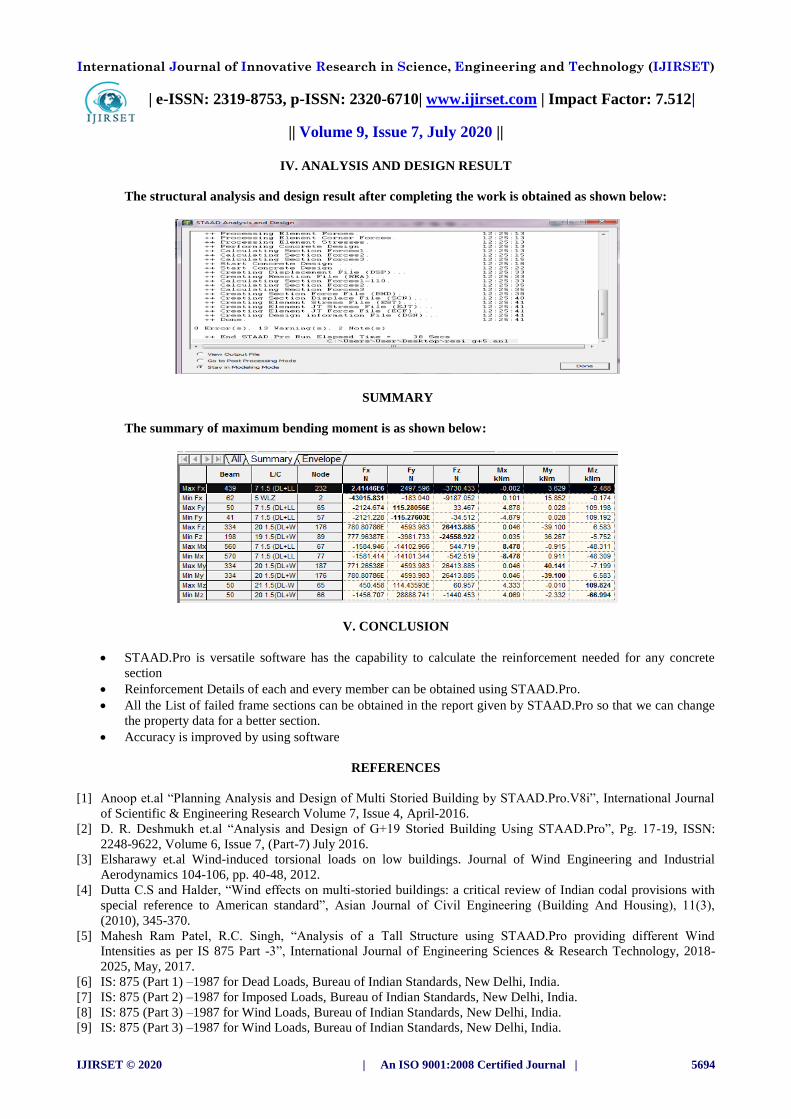
IV. ANALYSIS AND DESIGN RESULT
The structural analysis and design result after completing the work is obtained as shown below:
SUMMARY
The summary of maximum bending moment is as shown below:
V. CONCLUSION
STAAD.Pro is versatile software has the capability to calculate the reinforcement needed for any concrete
section
Reinforcement Details of each and every member can be obtained using STAAD.Pro.
All the List of failed frame sections can be obtained in the report given by STAAD.Pro so that we can change
the property data for a better section.
Accuracy is improved by using software
REFERENCES
[1] Anoop et.al “Planning Analysis and Design of Multi Storied Building by STAAD.Pro.V8i”, International Journal
of Scientific & Engineering Research Volume 7, Issue 4, April-2016.
[2] D. R. Deshmukh et.al “Analysis and Design of G+19 Storied Building Using STAAD.Pro”, Pg. 17-19, ISSN:
2248-9622, Volume 6, Issue 7, (Part-7) July 2016.
[3] Elsharawy et.al Wind-induced torsional loads on low buildings. Journal of Wind Engineering and Industrial
Aerodynamics 104-106, pp. 40-48, 2012.
[4] Dutta C.S and Halder, “Wind effects on multi-storied buildings: a critical review of Indian codal provisions with
special reference to American standard”, Asian Journal of Civil Engineering (Building And Housing), 11(3),
(2010), 345-370.
[5] Mahesh Ram Patel, R.C. Singh, “Analysis of a Tall Structure using STAAD.Pro providing different Wind
Intensities as per IS 875 Part -3”, International Journal of Engineering Sciences & Research Technology, 2018-
2025, May, 2017.
[6] IS: 875 (Part 1) –1987 for Dead Loads, Bureau of Indian Standards, New Delhi, India.
[7] IS: 875 (Part 2) –1987 for Imposed Loads, Bureau of Indian Standards, New Delhi, India.
[8] IS: 875 (Part 3) –1987 for Wind Loads, Bureau of Indian Standards, New Delhi, India.
[9] IS: 875 (Part 3) –1987 for Wind Loads, Bureau of Indian Standards, New Delhi, India.