wincc communication en-us en-us
TRANSCRIPT
8/20/2019 WinCC Communication en-US en-US
http://slidepdf.com/reader/full/wincc-communication-en-us-en-us 1/527
SIMATIC HMI
WinCC V7.3
WinCC: Communication
System Manual
Print of the Online Help
06/2014
A5E34374800-AA
Process communication
1
Allen Bradley - Ethernet IP
2
Mitsubishi Ethernet
3
Modbus TCPIP
4
OPC Channel
5
OPC - Open Connectivity
6
PROFIBUS FMS
7
S5 Ethernet Layer 4
8
S5 PROFIBUS FDL
9
S5 Programmers Port AS511
10
S5 Serial 3964R
11
SIMATIC S7 Protocol Suite
12
SIMATIC S7-1200, S7-1500
Channel
13
SIMATIC TI Ethernet Layer 4
14
SIMATIC TI Serial
15
SIMOTION
16
System Info
17
Communication - Diagnostics
18
8/20/2019 WinCC Communication en-US en-US
http://slidepdf.com/reader/full/wincc-communication-en-us-en-us 2/527
Legal information
Warning notice system
This manual contains notices you have to observe in order to ensure your personal safety, as well as to preventdamage to property. The notices referring to your personal safety are highlighted in the manual by a safety alertsymbol, notices referring only to property damage have no safety alert symbol. These notices shown below aregraded according to the degree of danger.
DANGER
indicates that death or severe personal injury will result if proper precautions are not taken.
WARNING
indicates that death or severe personal injury may result if proper precautions are not taken.
CAUTION
indicates that minor personal injury can result if proper precautions are not taken.
NOTICE
indicates that property damage can result if proper precautions are not taken.
If more than one degree of danger is present, the warning notice representing the highest degree of danger will be
used. A notice warning of injury to persons with a safety alert symbol may also include a warning relating to propertydamage.
Qualified Personnel
The product/system described in this documentation may be operated only bypersonnel qualified
for the specifictask in accordance with the relevant documentation, in particular its warning notices and safety instructions. Qualifiedpersonnel are those who, based on their training and experience, are capable of identifying risks and avoidingpotential hazards when working with these products/systems.
Proper use of Siemens products
Note the following:
WARNING
Siemens products may only be used for the applications described in the catalog and in the relevant technical
documentation. If products and components from other manufacturers are used, these must be recommended orapproved by Siemens. Proper transport, storage, installation, assembly, commissioning, operation andmaintenance are required to ensure that the products operate safely and without any problems. The permissibleambient conditions must be complied with. The information in the relevant documentation must be observed.
Trademarks
All names identified by ® are registered trademarks of Siemens AG. The remaining trademarks in this publicationmay be trademarks whose use by third parties for their own purposes could violate the rights of the owner.
Disclaimer of Liability
We have reviewed the contents of this publication to ensure consistency with the hardware and software described.Since variance cannot be precluded entirely, we cannot guarantee full consistency. However, the information inthis publication is reviewed regularly and any necessary corrections are included in subsequent editions.
Siemens AGIndustry Sector Postfach 48 4890026 NÜRNBERGGERMANY
A5E34374800-AAⓅ 08/2014 Subject to change
Copyright © Siemens AG 2014.All rights reserved
8/20/2019 WinCC Communication en-US en-US
http://slidepdf.com/reader/full/wincc-communication-en-us-en-us 3/527
Table of contents
1 Process communication.............................................................................................................................13
1.1 Communication Basics................................................................................................................13
1.2 Basic Rules for Configuring Connections....................................................................................14
1.3 WinCC process communication..................................................................................................15
1.3.1 WinCC process communication..................................................................................................15 1.3.2 Principle of WinCC communication.............................................................................................15 1.3.3 External tags...............................................................................................................................17 1.3.3.1 External tags...............................................................................................................................17
1.3.3.2 How to Create a New Connection...............................................................................................19 1.3.3.3 An external tag is configured as follows......................................................................................20 1.3.3.4 Format adaptation sorted by WinCC data type...........................................................................21 1.3.3.5 Format adaptation sorted by AS data type..................................................................................27 1.3.3.6 Principle of the BinWrite-Mechanism..........................................................................................35 1.3.3.7 How to Configure a Tag with "BinWrite"......................................................................................37 1.3.4 Port Addresses for Coupling via Ethernet...................................................................................39
2 Allen Bradley - Ethernet IP.........................................................................................................................41
2.1 WinCC Channel "Allen Bradley - Ethernet IP".............................................................................41
2.2 Channel Unit Assignment............................................................................................................42
2.3 Supported Data Types................................................................................................................43 2.4 Configuring the Channel..............................................................................................................44
2.4.1 Configuring the Channel "Allen Bradley - Ethernet IP"................................................................44 2.4.2 How to configure a "Allen Bradley E/IP PLC5" channel unit connection.....................................45 2.4.3 How to configure an "Allen Bradley E/IP SLC50x" channel unit connection...............................46 2.4.4 How to configure an "Allen Bradley E/IP ControlLogix" channel unit connection........................47 2.4.5 Examples: Communication path .................................................................................................48 2.4.6 Configuring the tags....................................................................................................................48 2.4.6.1 Configuring the tags....................................................................................................................48 2.4.6.2 Addressing..................................................................................................................................50 2.4.6.3 Addressing syntax.......................................................................................................................51 2.4.6.4 Addressing Types........................................................................................................................52
2.4.6.5 Examples for Addressing............................................................................................................53 2.4.6.6 How to configure a tag for the Allen Bradley E/IP ControlLogix channel unit.............................54 2.4.6.7 How to configure a tag with bit by bit access for Allen Bradley E/IP PLC5 or SLC50x...............55 2.4.6.8 How to configure a tag with byte by byte access for Allen Bradley E/IP PLC5 or SLC50x.. .......56 2.4.6.9 How to configure a tag with word by word access for Allen Bradley E/IP PLC5 or SLC50x. ......56 2.4.6.10 How to configure a text tag for Allen Bradley E/IP PLC5 or SLC50x..........................................57
3 Mitsubishi Ethernet.....................................................................................................................................59
3.1 WinCC channel "Mitsubishi Ethernet".........................................................................................59
3.2 Supported data types..................................................................................................................60
3.3 Configuring the Channel..............................................................................................................61
WinCC: CommunicationSystem Manual, 06/2014, A5E34374800-AA 3
8/20/2019 WinCC Communication en-US en-US
http://slidepdf.com/reader/full/wincc-communication-en-us-en-us 4/527
3.3.1 Configuring the "Mitsubishi Ethernet" channel............................................................................61 3.3.2 How to configure a "Mitsubishi FX3U Series" channel unit connection.......................................61 3.3.3 How to configure a "Mitsubishi Q Series" channel unit connection.............................................63
3.3.4 Configuring the tags....................................................................................................................64 3.3.4.1 Configuring the tags....................................................................................................................64 3.3.4.2 How to configure a tag................................................................................................................66
4 Modbus TCPIP...........................................................................................................................................69
4.1 "Modbus TCP/IP" channel...........................................................................................................69
4.2 Supported Data Types................................................................................................................70
4.3 Configuring the Channel..............................................................................................................71
4.3.1 Configuring the "Modbus TCPIP" Channel..................................................................................71 4.3.2 How to configure a connection....................................................................................................71 4.3.3 Configuring the tags....................................................................................................................73
4.3.3.1 Configuring the tags....................................................................................................................73 4.3.3.2 How to Configure a Tag with Bit by Bit Access...........................................................................75 4.3.3.3 How to Configure a Tag with Word by Word Access..................................................................76 4.3.3.4 How to Configure a Text Tag......................................................................................................77
5 OPC Channel.............................................................................................................................................79
5.1 WinCC OPC Channel..................................................................................................................79
5.2 OPC Item Manager.....................................................................................................................81
5.3 Overview of the Supported WinCC Data Types..........................................................................85
5.4 WinCC OPC DA Client................................................................................................................86
5.4.1 Functionality of the WinCC OPC DA Client.................................................................................86
5.4.2 How to Access a WinCC Tag with the OPC Item Manager.........................................................87 5.4.2.1 How to Access a WinCC Tag with the OPC Item Manager.........................................................87 5.4.2.2 Configuring the OPC Channel on the WinCC OPC DA Client....................................................88 5.4.2.3 Configuring Access with the OPC Item Manager........................................................................89 5.4.3 Accessing a WinCC Tag without the OPC Item Manager...........................................................93 5.4.4 Using Structures on a WinCC OPC DA Client............................................................................95 5.4.4.1 How to Use Structures on the WinCC OPC DA Client................................................................95 5.4.4.2 Configuring Structures and Structure Tags on the WinCC OPC DA Server...............................96 5.4.4.3 How to Configure Structures on the WinCC OPC DA Client.......................................................97 5.4.5 Error Handling in the Event of Disturbed OPC DA Communication............................................98 5.4.5.1 Error Handling in the Event of Disturbed OPC Communication..................................................98 5.4.5.2 WinCC as OPC DA Server..........................................................................................................99
5.4.5.3 WinCC as OPC DA Client.........................................................................................................101 5.5 WinCC OPC XML Client............................................................................................................103
5.5.1 Functionality of the WinCC OPC XML Client............................................................................103 5.5.2 How to Access a WinCC Tag with the OPC Item Manager.......................................................104 5.5.2.1 How to Access a WinCC Tag with the OPC Item Manager.......................................................104 5.5.2.2 Configuring Access with the OPC Item Manager......................................................................105 5.5.3 Accessing a WinCC Tag without the OPC Item Manager.........................................................108
5.6 WinCC OPC UA client...............................................................................................................111 5.6.1 Functionality of the WinCC OPC UA client................................................................................111 5.6.2 Accessing a tag using the OPC Item Manager.........................................................................111 5.6.2.1 Accessing an OPC tag using the OPC Item Manager...............................................................111 5.6.2.2 How to set up a server certificate..............................................................................................112
Table of contents
WinCC: Communication4 System Manual, 06/2014, A5E34374800-AA
8/20/2019 WinCC Communication en-US en-US
http://slidepdf.com/reader/full/wincc-communication-en-us-en-us 5/527
5.6.2.3 How to configure access to a tag using the OPC Item Manager...............................................114 5.6.3 Error handling in event of disturbed communication.................................................................118 5.6.3.1 WinCC as OPC UA server........................................................................................................119
5.6.3.2 WinCC as OPC UA client..........................................................................................................121
6 OPC - Open Connectivity.........................................................................................................................123
6.1 OPC - Open Connectivity..........................................................................................................123
6.2 Functionality of OPC.................................................................................................................124
6.3 OPC specifications and compatibility........................................................................................125
6.4 Using OPC in WinCC................................................................................................................126
6.5 How to configure Windows for the use of WinCC OPC.............................................................128
6.6 WinCC OPC XML DA Server....................................................................................................129
6.6.1 Mode of Operation.....................................................................................................................129 6.6.2 Installation.................................................................................................................................130 6.6.3 Setting security settings with IIS................................................................................................132 6.6.4 Testing the installation...............................................................................................................132
6.7 WinCC OPC DA server.............................................................................................................134 6.7.1 Functionality of the WinCC OPC DA Server.............................................................................134 6.7.2 Using Multiple OPC DA Servers................................................................................................135 6.7.3 Querying the OPC DA Server Name.........................................................................................136 6.7.4 Examples of OPC DA Connections...........................................................................................137 6.7.4.1 WinCC - WinCC Connection.....................................................................................................137 6.7.4.2 WinCC - SIMATIC NET FMS OPC Server Connection.............................................................141 6.7.4.3 WinCC - SIMATIC NET S7-OPC Server Connection................................................................143 6.7.4.4 WinCC - Microsoft Excel Connection........................................................................................149
6.8 WinCC OPC HDA server...........................................................................................................154 6.8.1 Functionality of the WinCC OPC HDA server...........................................................................154 6.8.2 Data Structure of a WinCC OPC HDA Server...........................................................................155 6.8.2.1 Data Structure of a WinCC OPC HDA Server...........................................................................155 6.8.2.2 Overview of the supported attributes.........................................................................................156 6.8.2.3 Overview of the supported assemblies.....................................................................................157 6.8.2.4 Overview of the supported functions.........................................................................................158 6.8.2.5 Time Format of a WinCC OPC HDA Server..............................................................................158 6.8.3 Quality codes.............................................................................................................................160 6.8.4 Supported Write-Accesses........................................................................................................161 6.8.5 Example of an OPC HDA Connection.......................................................................................163
6.8.5.1 Example of an OPC HDA Connection.......................................................................................163 6.8.5.2 HDA server browser..................................................................................................................164 6.8.5.3 How to Configure Access to a WinCC Archive Tag Using the HDA Server Browser................165 6.8.5.4 Reading Values of WinCC Archive Tags...................................................................................166 6.8.6 Special features of the OPC HDA server in WinCC for acyclic logging....................................168
6.9 WinCC OPC A&E Server..........................................................................................................171 6.9.1 Functionality of the WinCC OPC A&E server............................................................................171 6.9.2 Mapping of the WinCC Message System on OPC A&E............................................................172 6.9.2.1 Mapping of the WinCC Message System on OPC A&E....................................................172 6.9.2.2 Mapping the WinCC message classes and message types.....................................................173 6.9.2.3 Mapping the WinCC message priority.......................................................................................174 6.9.2.4 Attributes of the WinCC Message System................................................................................174
Table of contents
WinCC: CommunicationSystem Manual, 06/2014, A5E34374800-AA 5
8/20/2019 WinCC Communication en-US en-US
http://slidepdf.com/reader/full/wincc-communication-en-us-en-us 6/527
6.9.2.5 Acknowledgement theory..........................................................................................................176 6.9.3 Quality Codes for OPC A&E......................................................................................................178 6.9.4 Example of an OPC A&E Connection.......................................................................................178
6.9.4.1 Example of an OPC A&E Connection.......................................................................................178 6.9.4.2 How to Configure Access to the WinCC Message System.......................................................179 6.9.5 OPC A&E server with hierarchical access................................................................................181 6.9.5.1 Functionality of the OPC A&E server........................................................................................181 6.9.5.2 OPC A&E Server of WinCC V6.2 SP2 or higher.......................................................................183 6.9.5.3 Mapping the WinCC Message System on OPC A&E................................................................186 6.9.5.4 Quality Codes for OPC A&E......................................................................................................191 6.9.6 Reading archived messages.....................................................................................................192 6.9.6.1 Accessing archived events........................................................................................................192 6.9.6.2 Syntax for accessing archived messages using OPC...............................................................193 6.9.6.3 Read methods for archived messages......................................................................................194 6.9.6.4 Identifying archived messages..................................................................................................195
6.10 WinCC OPC UA Server.............................................................................................................197 6.10.1 Principle of operation the WinCC OPC UA Server ...................................................................197 6.10.2 Security concept of OPC UA.....................................................................................................198 6.10.3 Configuring the security mechanisms.......................................................................................202 6.10.4 Supported OPC UA services and profiles.................................................................................204 6.10.5 Name area of the WinCC OPC UA server................................................................................206 6.10.6 OPC UA Data Access...............................................................................................................208 6.10.7 OPC UA Log Access.................................................................................................................209 6.10.8 OPC UA alarm & conditions......................................................................................................210 6.10.9 Attributes of the WinCC message system.................................................................................214 6.10.10 Configuring the WinCC OPC UA server....................................................................................215 6.10.10.1 Configuration file..................................................................................................................215
6.10.10.2 How to configure the OPC UA server..................................................................................217
6.11 Trace.........................................................................................................................................220
7 PROFIBUS FMS.......................................................................................................................................221
7.1 WinCC channel "PROFIBUS FMS"...........................................................................................221
7.2 Data type of the tags.................................................................................................................222
7.3 Configuring the Channel............................................................................................................223
7.3.1 Configuring a connection ..........................................................................................................223 7.3.1.1 Configuring a connection...........................................................................................................223 7.3.1.2 Configuring the connection in configuration mode....................................................................223 7.3.1.3 How to configure the connection in Runtime.............................................................................226
7.3.2 Configuring the tags..................................................................................................................227 7.3.2.1 Configuring the tags..................................................................................................................227 7.3.2.2 Configuring the address of the tags in configuration mode.......................................................228 7.3.2.3 How to configure the address of the tags in runtime.................................................................229
8 S5 Ethernet Layer 4..................................................................................................................................231
8.1 WinCC Channel "SIMATIC S5 Ethernet Layer 4".....................................................................231
8.2 Data type of the tags.................................................................................................................232
8.3 Configuring the Channel............................................................................................................233
8.3.1 Configuring the channel "SIMATIC S5 Ethernet Layer 4".........................................................233 8.3.2 How to configure the connection...............................................................................................233
Table of contents
WinCC: Communication6 System Manual, 06/2014, A5E34374800-AA
8/20/2019 WinCC Communication en-US en-US
http://slidepdf.com/reader/full/wincc-communication-en-us-en-us 7/527
8.3.3 Configuring the tags..................................................................................................................235 8.3.3.1 Configuring the tags..................................................................................................................235 8.3.3.2 Addresses of tags......................................................................................................................235
8.3.3.3 How to Configure a Tag with Bit by Bit Access.........................................................................237 8.3.3.4 How to Configure a Tag with Byte by Byte Access...................................................................238 8.3.3.5 How to Configure a Tag with Word by Word Access................................................................239 8.3.3.6 How to configure a raw data tag................................................................................................241 8.3.4 System parameters...................................................................................................................242 8.3.4.1 System parameters of the channel unit.....................................................................................242 8.3.4.2 How to Change the Device Name.............................................................................................243 8.3.4.3 How to change the transport parameter....................................................................................244
8.4 Appendix...................................................................................................................................246 8.4.1 Appendix...................................................................................................................................246 8.4.2 Internal error codes and constants............................................................................................246 8.4.2.1 Internal error codes and constants............................................................................................246 8.4.2.2 Error codes during connection disturbances.............................................................................246 8.4.2.3 iNA960 messages.....................................................................................................................249 8.4.2.4 SCI messages...........................................................................................................................250
9 S5 PROFIBUS FDL..................................................................................................................................253
9.1 WinCC channel "SIMATIC S5 Profibus FDL"............................................................................253
9.2 Supported data types and data ranges.....................................................................................255
9.3 Features of the WinCC channel "SIMATIC S5 Profibus FDL"...................................................256
9.4 Configuring the Channel............................................................................................................258
9.4.1 How to configure the channel "SIMATIC S5 Profibus FDL"......................................................258 9.4.2 Channel unit "FDL (CP5412/A2-1)"...........................................................................................258 9.4.3 How to configure a connection..................................................................................................259 9.4.4 Configuring the tags..................................................................................................................261 9.4.4.1 Configuring the tags..................................................................................................................261 9.4.4.2 How to Configure a Tag with Bit by Bit Access.........................................................................261 9.4.4.3 How to Configure a Tag with Byte by Byte Access...................................................................262 9.4.4.4 How to configure a tag with word by word access....................................................................263 9.4.5 System parameters...................................................................................................................264 9.4.5.1 System parameters of the channel unit.....................................................................................264 9.4.5.2 How to Change the Device Name.............................................................................................265 9.4.5.3 How to change the write/read monitoring time of process values.............................................266
9.5 Special Functions......................................................................................................................267
9.5.1 Special functions of the "SIMATIC S5 Profibus FDL" Channel.................................................267 9.5.2 Raw data tags of the "SIMATIC S5 Profibus FDL" channel......................................................267 9.5.2.1 Raw data tags of the "SIMATIC S5 Profibus FDL" channel......................................................267 9.5.2.2 How to configure raw data tags.................................................................................................267 9.5.3 Configuring the communication types.......................................................................................268 9.5.3.1 Configuring the communication types.......................................................................................268 9.5.3.2 How to configure an active data transfer...................................................................................269 9.5.3.3 How to configure a passive data transfer..................................................................................271
9.6 Example of configuring the "SIMATIC S5 Profibus FDL" channel.............................................273 9.6.1 Example of configuring the "SIMATIC S5 Profibus FDL" channel.............................................273 9.6.2 How to configure the data handling blocks in the AS................................................................273 9.6.3 How to configure an I/O Field....................................................................................................276
Table of contents
WinCC: CommunicationSystem Manual, 06/2014, A5E34374800-AA 7
8/20/2019 WinCC Communication en-US en-US
http://slidepdf.com/reader/full/wincc-communication-en-us-en-us 8/527
10 S5 Programmers Port AS511...................................................................................................................279
10.1 WinCC channel "SIMATIC S5 Programmers Port AS511" .......................................................279
10.2 Data type of the tags.................................................................................................................280
10.3 Configuring the Channel............................................................................................................281 10.3.1 Configuring the "SIMATIC S5 Programmers Port AS511" channel...........................................281 10.3.2 How to configure the connection...............................................................................................281 10.3.3 Configuring the tags..................................................................................................................283 10.3.3.1 Configuring the tags..................................................................................................................283 10.3.3.2 How to configure the address of a tag.......................................................................................283 10.3.3.3 How to configure a tag with bit-wise access..............................................................................286 10.3.3.4 How to Configure a Tag with Byte by Byte Access...................................................................287
11 S5 Serial 3964R.......................................................................................................................................289
11.1 WinCC channel "SIMATIC S5 Serial 3964R" ...........................................................................289
11.2 Data type of the tags.................................................................................................................290
11.3 Configuring the Channel............................................................................................................291
11.3.1 Configuring the "SIMATIC S5 Serial 3964R" channel...............................................................291 11.3.2 How to configure the connection...............................................................................................291 11.3.3 Configuring the tags..................................................................................................................293 11.3.3.1 Configuring the tags..................................................................................................................293 11.3.3.2 How to configure the address of the tag....................................................................................293 11.3.3.3 How to configure a tag with bit-wise access..............................................................................295 11.3.3.4 How to Configure a Tag with Byte by Byte Access...................................................................297
12 SIMATIC S7 Protocol Suite......................................................................................................................299
12.1 "SIMATIC S7 Protocol Suite" Channel......................................................................................299
12.2 WinCC Channel "SIMATIC S7 Protocol Suite"..........................................................................300
12.3 Channel unit selection...............................................................................................................302
12.4 Overview of the supported data types.......................................................................................306
12.5 Configuring the Channel............................................................................................................307 12.5.1 "SIMATIC S7 Protocol Suite" Channel - Configuration.............................................................307 12.5.2 How to configure the "SIMATIC S7 Protocol Suite" channel.....................................................307 12.5.3 Channel units............................................................................................................................308 12.5.3.1 Channel units of the "SIMATIC S7 Protocol Suite" channel......................................................308 12.5.3.2 "Industrial Ethernet (I+II)" channel units".................................................................................. .309
12.5.3.3 "MPI" channel unit.....................................................................................................................312 12.5.3.4 "Named Connections" channel unit...........................................................................................314 12.5.3.5 "PROFIBUS (I+II)" channel units............................................................................................. ..317 12.5.3.6 "Slot PLC" channel unit.............................................................................................................319 12.5.3.7 "Soft PLC" channel unit........................................................................................................... ..321 12.5.3.8 "TCP/IP" channel unit................................................................................................................322 12.5.4 Configuring the tags..................................................................................................................325 12.5.4.1 Configuring the tags..................................................................................................................325 12.5.4.2 How to Configure a Tag with Bit by Bit Access.........................................................................325 12.5.4.3 How to Configure a Tag with Byte by Byte Access...................................................................327 12.5.4.4 How to Configure a Tag with Word by Word Access................................................................328 12.5.4.5 How to Configure a Text Tag....................................................................................................329
Table of contents
WinCC: Communication8 System Manual, 06/2014, A5E34374800-AA
8/20/2019 WinCC Communication en-US en-US
http://slidepdf.com/reader/full/wincc-communication-en-us-en-us 9/527
12.5.5 System parameters...................................................................................................................331 12.5.5.1 System Parameters of the Channel Unit...................................................................................331 12.5.5.2 Cyclic read services in PLC.................................................................................................... ...332
12.5.5.3 How to Configure the System Parameters................................................................................333 12.5.5.4 How to Change the Logical Device Name.............................................................................. ...335
12.6 Special functions.......................................................................................................................337 12.6.1 Special functions of the "SIMATIC S7 Protocol Suite" Channel................................................337 12.6.2 Data exchange with the S7 function block AR_SEND...............................................................337 12.6.2.1 Data exchange with the S7 function block AR_SEND.............................................................. .337 12.6.2.2 Data Block - Structure and Parameters.....................................................................................338 12.6.2.3 Overview of the properties of the AR_SEND variants...............................................................343 12.6.2.4 AR_SEND variant for an archive tag.........................................................................................345 12.6.2.5 Example 1 for data block structure: An archive tag; each process value has a time stamp. ....347 12.6.2.6 Example 2 for data block structure: One archive tag; equally spaced time stamp....................347 12.6.2.7 Example 3 for data block structure: An archive tag; each process value has its own time
stamp.........................................................................................................................................348 12.6.2.8 Example 4 for data block structure: An archive tag; each process value with relative time
stamp (time difference)..............................................................................................................349 12.6.2.9 AR_SEND variant for multiple archive tags............................................................................. ..350 12.6.2.10 Example 5 for data block structure: Multiple archive tags; each process value has its
own time stamp....................................................................................................................354 12.6.2.11 Example 6 for data block structure: Multiple archive tags; equally spaced time stamp.. .....356 12.6.2.12 Example 7 for data block structure: Multiple archive tags; each process value has its
own time stamp....................................................................................................................358 12.6.2.13 Example 8 for data block structure: Multiple archive tags; process values with relative
time stamp (time difference).................................................................................................360 12.6.2.14 AR_SEND variant for multiple archive tags (optimized).......................................................362
12.6.2.15 Example 9 for data block structure: multiple archive tags;optimized...................................363 12.6.2.16 How to configure the AR _SEND variant for an archive tag.................................................364 12.6.2.17 How to configure the AR _SEND variant for multiple archive tags.......................................367 12.6.3 Raw data tags of the Channel "SIMATIC S7 Protocol Suite"....................................................369 12.6.3.1 Raw data tags of the Channel "SIMATIC S7 Protocol Suite"....................................................369 12.6.3.2 Raw data tag as byte array.......................................................................................................370 12.6.3.3 How to Configure a Raw Data Tag as Byte Array.....................................................................371 12.6.3.4 Raw data tag for BSEND/BRCV functions of S7 communication..............................................373 12.6.3.5 How to Configure a Raw Data Tag for ""BSEND/BRCV" functions...........................................376 12.6.4 Software Redundancy...............................................................................................................377 12.6.4.1 Software Redundancy............................................................................................................. ..377 12.6.4.2 Software Redundancy - Connection-specific internal tags........................................................379
12.6.4.3 How To Configure a Software Redundancy..............................................................................383 12.6.4.4 How to Clear a Software Redundancy in WinCC......................................................................386 12.6.4.5 How to Check the WinCC Startup Parameters.........................................................................386 12.6.4.6 How To Load WinCC's system messages into Alarm Logging.................................................387 12.6.4.7 Error codes during connection disturbances.............................................................................387
13 SIMATIC S7-1200, S7-1500 Channel......................................................................................................389
13.1 "SIMATIC S7-1200, S7-1500 Channel" channel.......................................................................389
13.2 Overview of the supported data types.......................................................................................390
13.3 Configuring the channel............................................................................................................391
13.3.1 Configuration of the "SIMATIC S7-1200, S7-1500 Channel" channel.......................................391 13.3.2 How to configure a connection..................................................................................................391
Table of contents
WinCC: CommunicationSystem Manual, 06/2014, A5E34374800-AA 9
8/20/2019 WinCC Communication en-US en-US
http://slidepdf.com/reader/full/wincc-communication-en-us-en-us 10/527
13.3.3 How to configure a tag without optimized block access............................................................392 13.3.4 How to configure a tag with optimized block access.................................................................394
14 SIMATIC TI Ethernet Layer 4...................................................................................................................397
14.1 WinCC channel "SIMATIC TI Ethernet Layer 4".......................................................................397
14.2 Data type of the tags.................................................................................................................398
14.3 Configuring the Channel............................................................................................................399
14.3.1 Configuring the channel "SIMATIC TI Ethernet Layer 4"..........................................................399 14.3.2 How to configure the connection...............................................................................................399 14.3.3 Configuring the tags..................................................................................................................401 14.3.3.1 Configuring the tags..................................................................................................................401 14.3.3.2 How to configure the address of a tag.......................................................................................401 14.3.3.3 How to configure a tag with bit-wise access..............................................................................403 14.3.3.4 How to Configure a Tag with Byte by Byte Access...................................................................404
14.3.4 System parameters...................................................................................................................405 14.3.4.1 System parameters of the channel unit.....................................................................................405 14.3.4.2 How to Change the Device Name.............................................................................................406 14.3.4.3 How to change the transport parameter....................................................................................407
15 SIMATIC TI Serial.....................................................................................................................................409
15.1 WinCC channel "SIMATIC TI Serial" ........................................................................................409
15.2 Data type of the tags.................................................................................................................410
15.3 Configuring the Channel............................................................................................................411
15.3.1 Configuring the "SIMATIC TI Serial" channel............................................................................411 15.3.2 How to configure the connection...............................................................................................411 15.3.3 Configuring the tags..................................................................................................................413 15.3.3.1 Configuring the tags..................................................................................................................413 15.3.3.2 How to configure the address of a tag.......................................................................................413 15.3.3.3 How to configure a tag with bit-wise access..............................................................................414 15.3.3.4 How to Configure a Tag with Byte by Byte Access...................................................................415
16 SIMOTION................................................................................................................................................417
16.1 WinCC channel "SIMOTION"....................................................................................................417
16.2 Overview of the supported data types.......................................................................................418
16.3 Configuring the channel............................................................................................................419
16.3.1 Configuration of the "SIMOTION" channel................................................................................419 16.3.2 How to export a SIMOTION SCOUT project ............................................................................419
16.3.3 How to create a WinCC project with Simotion Mapper.............................................................420 16.3.4 How to change a WinCC project with Simotion Mapper............................................................421 16.3.5 How to change the connection parameters...............................................................................423 16.3.6 How to change the tag address.................................................................................................424 16.3.7 System parameter configuration...............................................................................................425 16.3.7.1 System Parameters of the Channel Unit...................................................................................425 16.3.7.2 How to Configure the System Parameters................................................................................425 16.3.7.3 How to Change the Logical Device Name.................................................................................427
16.4 Diagnosis "SIMOTION" channel................................................................................................429 16.4.1 Diagnosis possibilities of the "SIMOTION" channel..................................................................429 16.4.2 Description of Log File Entries..................................................................................................429
Table of contents
WinCC: Communication10 System Manual, 06/2014, A5E34374800-AA
8/20/2019 WinCC Communication en-US en-US
http://slidepdf.com/reader/full/wincc-communication-en-us-en-us 11/527
17 System Info...............................................................................................................................................433
17.1 "System Info" Channel..............................................................................................................433
17.2 WinCC System Info Channel.....................................................................................................434
17.3 Overview of the Supported System Information........................................................................436
17.4 Differences to Other Software Components..............................................................................441
17.5 Configuring the Channel............................................................................................................442 17.5.1 How to Configure the System Info Channel..............................................................................442
17.6 Examples of Evaluating and Displaying System Information....................................................443 17.6.1 How To Call Up and Evaluate System Information...................................................................443 17.6.2 How to Configure a Tag in the System Info Channel................................................................443 17.6.3 How to Display the Time in an I/O Field....................................................................................444 17.6.4 How to Display the Free Disk Capacity in a Bar Graph.............................................................446 17.6.5 How to Display the CPU Load in a Trend Window....................................................................447 17.6.6 How to Configure a Message Regarding Free Disk Capacity...................................................448 17.6.7 How to Display a Message regarding the Available Disk Capacity...........................................450 17.6.8 How to Display the Printer Status in a Status Display...............................................................452 17.6.9 How to Check the WinCC Startup Parameters.........................................................................454 17.6.10 How to Insert a Bar Graph.........................................................................................................454 17.6.11 How to Insert an I/O Field..........................................................................................................455 17.6.12 How to Start Runtime................................................................................................................455
17.7 Special Functions......................................................................................................................456 17.7.1 Use in Multi-User and Client Systems.......................................................................................456 17.7.1.1 Use in Multi-User and Client Systems..................................................................................... ..456 17.7.2 Example of monitoring system information from multiple servers.............................................456 17.7.2.1 Monitoring the system information of several servers on a WinCC client.................................456 17.7.2.2 How to Configure the First Server.............................................................................................457 17.7.2.3 How to Configure the Second Server........................................................................................458 17.7.2.4 How to Import the Tags to the WinCC Client............................................................................459 17.7.2.5 How to Configure the Process Picture on the WinCC Client.....................................................460 17.7.2.6 How to Activate the Project.......................................................................................................461
18 Communication - Diagnostics...................................................................................................................463
18.1 Diagnosis of Channels and Tags..............................................................................................463
18.2 General Information about Error Detection...............................................................................464
18.3 Channel Diagnosis ...................................................................................................................465
18.3.1 Channel diagnosis.....................................................................................................................465 18.3.2 "Status - Logical Connections" Function...................................................................................465 18.3.3 How to Use the "Status - Logical Connections" Function to Check a Channel.........................465 18.3.4 Diagnosis of Channels with Channel Diagnosis........................................................................467 18.3.4.1 Principle of Channel Diagnosis.................................................................................................467 18.3.4.2 Channel Diagnosis with ActiveX Control...................................................................................468 18.3.4.3 How to Check a Channel with Channel Diagnosis as an ActiveX Control................................468 18.3.4.4 Diagnosing a Channel with "Channel Diagnosis"......................................................................469 18.3.4.5 How to Check a Channel with Channel Diagnosis....................................................................470 18.3.4.6 How to Configure the Trace Function of a Channel..................................................................471 18.3.4.7 How to Start Runtime................................................................................................................472
18.4 Diagnosis of "System Info" Channel..........................................................................................473
Table of contents
WinCC: CommunicationSystem Manual, 06/2014, A5E34374800-AA 11
8/20/2019 WinCC Communication en-US en-US
http://slidepdf.com/reader/full/wincc-communication-en-us-en-us 12/527
18.4.1 "System Info" Channel - Diagnostic Options.............................................................................473 18.4.2 Description of Log File Entries..................................................................................................473 18.4.3 Determining the Cause of Incorrect Tag Values.......................................................................474
18.4.3.1 How to Determine the Cause of Incorrect Tags........................................................................474 18.4.3.2 How to Check the Channel and the Connection.......................................................................474 18.4.3.3 How to Check a Tag..................................................................................................................476
18.5 Diagnosis of the "SIMATIC S7 Protocol Suite" Channel...........................................................478 18.5.1 "SIMATIC S7 Protocol Suite" Channel - Diagnostic Options.....................................................478 18.5.2 Description of Log File Entries..................................................................................................478 18.5.3 Determining the Cause of Incorrect Tag Values.......................................................................481 18.5.3.1 How to Determine the Cause of Incorrect Tags........................................................................481 18.5.3.2 How to Check the Configuration of the Communication Processor..........................................481 18.5.3.3 Checking the Communication Processor under SIMATIC NET................................................483 18.5.3.4 How to Check the Configuration of the Connection and Tags..................................................484 18.5.3.5 How to Check the Channel and the Connection.......................................................................485 18.5.3.6 How to Check a Tag..................................................................................................................487
18.6 Diagnosis of the "SIMATIC S5 Profibus FDL" Channel.............................................................489 18.6.1 Diagnostic Options for the "SIMATIC S5 PROFIBUS FDL" Channel........................................489 18.6.2 Description of Log File Entries..................................................................................................489 18.6.3 Determining the Cause of Incorrect Tag Values.......................................................................490 18.6.3.1 How to Determine the Cause of Incorrect Tags........................................................................490 18.6.3.2 How to Check the Configuration of the Communication Processor..........................................491 18.6.3.3 Checking the Communication Processor under SIMATIC NET................................................492 18.6.3.4 How to Check the Configuration of the Connection and Tags..................................................493 18.6.3.5 How to Check the Channel and the Connection.......................................................................495 18.6.3.6 How to Check a Tag..................................................................................................................497
18.7 Diagnosis of the "OPC" Channel...............................................................................................498 18.7.1 Possibilities for Diagnosing the "OPC" Channel........................................................................498 18.7.2 Description of Log File Entries..................................................................................................498 18.7.2.1 Description of Log File Entries..................................................................................................498 18.7.2.2 Entries for "INFO" Flag..............................................................................................................499 18.7.2.3 Entries for "ERROR" Flag.........................................................................................................500 18.7.3 Determining the Cause of Incorrect Tag Values.......................................................................501 18.7.3.1 How to Determine the Cause of Invalid Tags............................................................................501 18.7.3.2 How to Check the Configuration Data.......................................................................................502 18.7.3.3 How to Check the Channel and the Connection.......................................................................503 18.7.3.4 How to Check a Tag..................................................................................................................505
18.8 Quality of Tags..........................................................................................................................506
18.8.1 Quality of Tags..........................................................................................................................506 18.8.2 Quality Codes of Tags...............................................................................................................508 18.8.3 Tag Status.................................................................................................................................513 18.8.4 Using the Tag Status to Monitor Connection Status.................................................................515 18.8.5 Monitoring Tag Status Using Global Actions.............................................................................516 18.8.6 How to Check an Internal Tag...................................................................................................517
Index.........................................................................................................................................................519
Table of contents
WinCC: Communication12 System Manual, 06/2014, A5E34374800-AA
8/20/2019 WinCC Communication en-US en-US
http://slidepdf.com/reader/full/wincc-communication-en-us-en-us 13/527
Process communication
1
1.1 Communication Basics
Introduction
Communication is defined as the exchange of data between two communication partners.
Communication
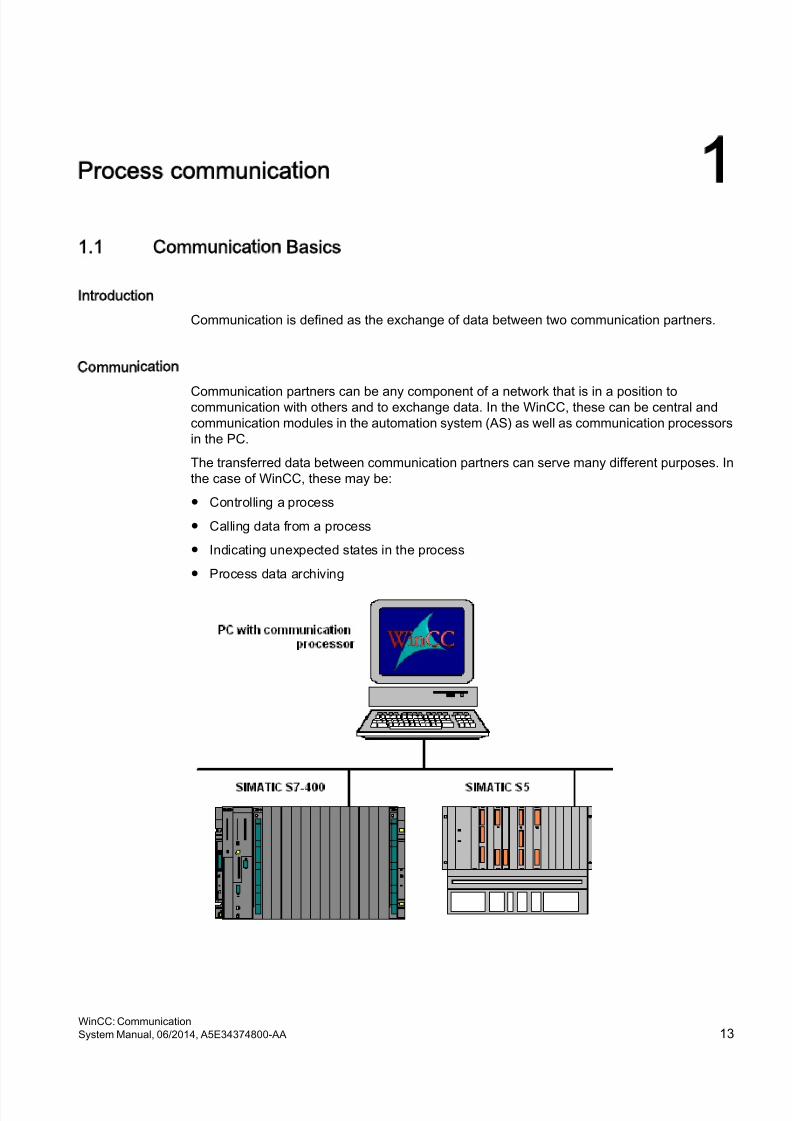
Communication partners can be any component of a network that is in a position tocommunication with others and to exchange data. In the WinCC, these can be central andcommunication modules in the automation system (AS) as well as communication processorsin the PC.
The transferred data between communication partners can serve many different purposes. Inthe case of WinCC, these may be:
● Controlling a process
● Calling data from a process
● Indicating unexpected states in the process
● Process data archiving
WinCC: CommunicationSystem Manual, 06/2014, A5E34374800-AA 13
8/20/2019 WinCC Communication en-US en-US
http://slidepdf.com/reader/full/wincc-communication-en-us-en-us 14/527
1.2 Basic Rules for Configuring Connections
Acquisition cycle and update time
The acquisition cycles for the tags defined in the configuration software are major factors forthe achievable update times.
The update time is the sum of the acquisition cycle, the transmission time and the processingtime.
To achieve optimum update times, remember the following points during configuration:
● Optimize the maximum and minimum size of the data areas.
● Define data areas that belong together as belonging together. If you set up one large areainstead of multiple small areas, it improves the update time.
● Acquisition cycles that are too small decrease performance. Set the acquisition cycleaccording to the rate of change of the process values. Take the temperature of an oven forexample, it changes much more slowly than the speed of an electrical drive.
● Put the tags of an alarm or a screen in one data area without gaps.
● Changes in the controller can only be detected reliably if these are available for at leastone acquisition cycle.
● Set the transmission rate to the highest possible value for error-free transmission.
Images
The refresh rate of screens is determined by the type and volume of data to be visualized.
In the interest of short update times, ensure that you only configure short acquisition times forobjects that require fast updates.
Curves
When using bit-triggered curves, if the group bit is set in the "Curve transfer area", all curvesfor which the bit is set in this area are updated on the WinCC station. It resets the bits in thenext cycle.
Only after all bits have been reset in the WinCC station may the group bit be set again in thePLC program.
Process communication
1.2 Basic Rules for Configuring Connections
WinCC: Communication14 System Manual, 06/2014, A5E34374800-AA
8/20/2019 WinCC Communication en-US en-US
http://slidepdf.com/reader/full/wincc-communication-en-us-en-us 15/527
1.3 WinCC process communication
1.3.1 WinCC process communication
Introduction
You can access process tags (external tags) in an automation system from WinCC. Beforeyou configure the process link in WinCC however, you should use a checklist to check whetherthe following prerequisites have been met:
● The automation system must be equipped with a communication interface supported by acommunication driver in WinCC.
● This interface must be configured in the automation system so that the controller programcan access the interface with the communication calls. The configuration parameters forthe communication hardware must be known.
● The addresses of the tags that WinCC should access must be known. Note that theaddresses depend on the automation system.
● The respective communication hardware (communication processor, standard I/O portCOMx, ...) must be installed in the WinCC system. In order to install this hardware, thesupplied operating system driver (hardware driver) must also have been installedpreviously. The settings for the hardware and software of the communication processormust be known.
● Depending on the communication processor used in the WinCC system, more settings may
have to be made. When using industrial Ethernet or PROFIBUS for example, a localdatabase must be created. This connection parameter also has to be known.
For operation in runtime, a physical connection must also exist between WinCC and the AS,so that you can access the external tags.
1.3.2 Principle of WinCC communication
Introduction
WinCC manages its tags centrally using so-called tag management. All of data and tagscreated in the project and stored in the project database are captured and management inruntime by WinCC.All applications, such as e.g. Graphics Runtime, Alarm Logging Runtime or Tag LoggingRuntime (Global Script), must request the data in the for of WinCC tags from tag management.
Communication between WinCC and Automation systems (AS)
Communication in the industrial communication with WinCC means that information isexchanged with tags and process values. To capture the process values, the WinCCcommunication driver sends request telegrams to the AS. This in turn sends the requestedprocess values back to WinCC in corresponding response telegrams.
Process communication
1.3 WinCC process communication
WinCC: CommunicationSystem Manual, 06/2014, A5E34374800-AA 15
8/20/2019 WinCC Communication en-US en-US
http://slidepdf.com/reader/full/wincc-communication-en-us-en-us 16/527
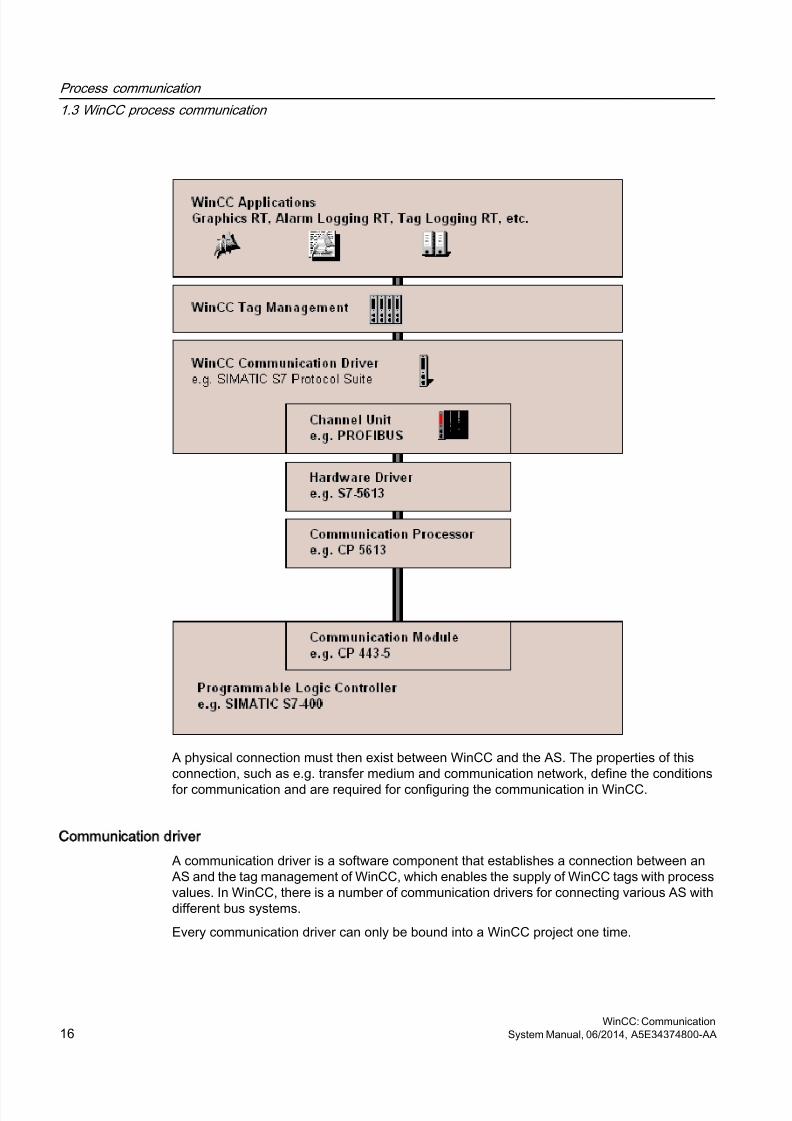
A physical connection must then exist between WinCC and the AS. The properties of thisconnection, such as e.g. transfer medium and communication network, define the conditions
for communication and are required for configuring the communication in WinCC.
Communication driver
A communication driver is a software component that establishes a connection between anAS and the tag management of WinCC, which enables the supply of WinCC tags with processvalues. In WinCC, there is a number of communication drivers for connecting various AS withdifferent bus systems.
Every communication driver can only be bound into a WinCC project one time.
Process communication
1.3 WinCC process communication
WinCC: Communication16 System Manual, 06/2014, A5E34374800-AA
8/20/2019 WinCC Communication en-US en-US
http://slidepdf.com/reader/full/wincc-communication-en-us-en-us 17/527
Communication drivers under WinCC are also called "Channels" and have the file extension"*.chn". All of the communication drivers installed on the computer are located in subdirectory"\bin" in the WinCC installation directory.
A communication driver has different channel units for different communication networks.
Channel Unit
Every channel unit serves as an interface with exactly one underlying hardware driver andtherefore to exactly one communication processor in the PC. Every channel unit used musttherefore be allocated with the respective communication processor.
For some channel units, an additional configuration is performed in the so-called systemparameters. For channel units that work on the transport layer (Layer 4) of the OSI model, thetransport parameters are also defined.
Connection (logical)
If WinCC and the AS are correctly connected, physically, then a communication driver and acorresponding channel unit are required in WinCC in order to create or configure a (logical)connection with the AS. The data exchange will take place via this connection in Runtime.In WinCC, there is a connection of a configured, logical allocation of two communicationpartners for executing a certain communication service. Every connection has two end pointsthat also contain necessary information for addressing the communication partner and otherattributes for establishing the connection.A connection is configured under a channel unit with your specific connection parameters. Anumber of connections can also be created under one channel unit, depending on thecommunication driver.
1.3.3 External tags
1.3.3.1 External tags
Introduction
In order to obtain certain data of an AS, WinCC tags are required. These tags that affect the
connection to an AS are designated as external tags. Other tags that have no processconnection are designated as internal tags.
Data Type and Type Conversion
In configuring external tags, besides tag names you must define a data type and with somedata types a type conversion is required:
The data type determines the data format in WinCC. Along with the type conversion, theconversion from AS format to the WinCC format is defined. The type conversion applies forboth transfer directions:
Process communication
1.3 WinCC process communication
WinCC: CommunicationSystem Manual, 06/2014, A5E34374800-AA 17
8/20/2019 WinCC Communication en-US en-US
http://slidepdf.com/reader/full/wincc-communication-en-us-en-us 18/527
● In the AS: e.g. for certain functions (such as timer values / BCD displays) or with theinformation to be addressed (e.g. byte, word addresses in data block or I/O area).
● In WinCC: e.g. for analog value processing or calculations.
In practice, normally the AS data format is normally defined. The following possibilities areavailable for selecting the WinCC format:
● The WinCC data format can match the AS format. This is done by selecting a typeconversion that uses the same formats on both sides and considers the leading signindependent of the WinCC data type, e.g. "WordToSignedWord". If this cannot be achievedwith the selected data type, it must be changed in WinCC.
● The WinCC format is set up in accordance of the value processing in WinCC.
When selecting the data type and the type conversion, if required, the following points areimportant:
● Leading sign: Should it be considered for the adaptation? Can negative tag values alsooccur during operation? (such as e.g. with control differences as percentage)
● Value Range: Are tag values that occur during operation in the value range of both formatsor can a possible overflow of the value be expected in WinCC or the AS ? If an overflowoccurs, a value cannot be displayed on the other side or it can lead to faults in subsequentprocessing.
● Different type conversions with the same value range: It is possible that different typeconversions of a data type have the same value range. E.g. "ByteToUnsignedDword" and"ByteToUnsignedWord" with value range [0...127]. In this case, check which format isdefined for the data from the AS and whether this format wastes resources unnecessarilybecause of over-dimensioning. (E.g. DWord instead of Word).
If the value range required in the AS is not covered by the selected type conversion, you mustchange the data type in WinCC.
Note
Communication to the automation system can be disrupted when a process tag is configuredincorrectly, for example, due to an address error.
WinCC data types and type conversion
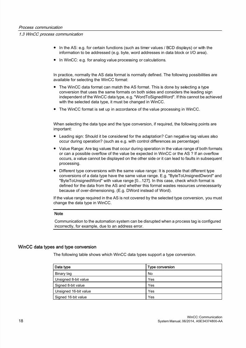
The following table shows which WinCC data types support a type conversion.
Data type Type conversion
Binary tag No
Unsigned 8-bit value Yes
Signed 8-bit value Yes
Unsigned 16-bit value Yes
Signed 16-bit value Yes
Process communication
1.3 WinCC process communication
WinCC: Communication18 System Manual, 06/2014, A5E34374800-AA
8/20/2019 WinCC Communication en-US en-US
http://slidepdf.com/reader/full/wincc-communication-en-us-en-us 19/527
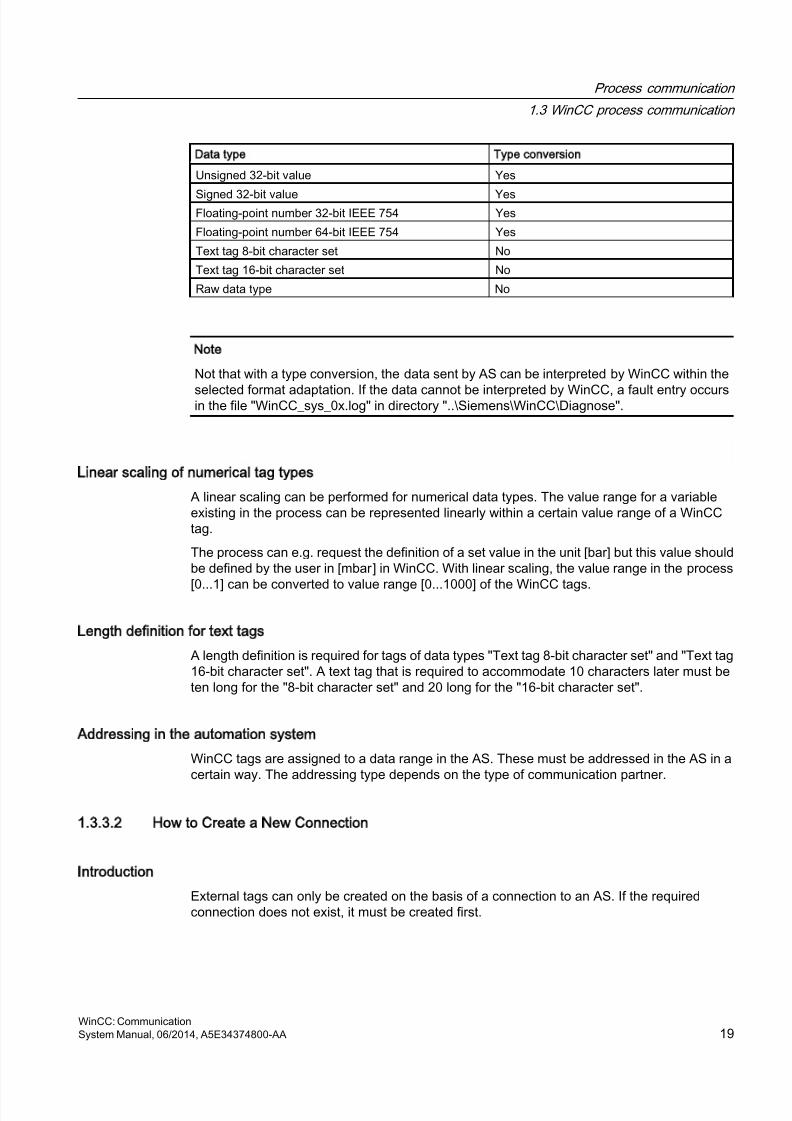
Data type Type conversion
Unsigned 32-bit value Yes
Signed 32-bit value YesFloating-point number 32-bit IEEE 754 Yes
Floating-point number 64-bit IEEE 754 Yes
Text tag 8-bit character set No
Text tag 16-bit character set No
Raw data type No
Note
Not that with a type conversion, the data sent by AS can be interpreted by WinCC within the
selected format adaptation. If the data cannot be interpreted by WinCC, a fault entry occursin the file "WinCC_sys_0x.log" in directory "..\Siemens\WinCC\Diagnose".
Linear scaling of numerical tag types
A linear scaling can be performed for numerical data types. The value range for a variableexisting in the process can be represented linearly within a certain value range of a WinCCtag.
The process can e.g. request the definition of a set value in the unit [bar] but this value shouldbe defined by the user in [mbar] in WinCC. With linear scaling, the value range in the process
[0...1] can be converted to value range [0...1000] of the WinCC tags.
Length definition for text tags
A length definition is required for tags of data types "Text tag 8-bit character set" and "Text tag16-bit character set". A text tag that is required to accommodate 10 characters later must beten long for the "8-bit character set" and 20 long for the "16-bit character set".
Addressing in the automation system
WinCC tags are assigned to a data range in the AS. These must be addressed in the AS in acertain way. The addressing type depends on the type of communication partner.
1.3.3.2 How to Create a New Connection
Introduction
External tags can only be created on the basis of a connection to an AS. If the requiredconnection does not exist, it must be created first.
Process communication
1.3 WinCC process communication
WinCC: CommunicationSystem Manual, 06/2014, A5E34374800-AA 19

8/20/2019 WinCC Communication en-US en-US
http://slidepdf.com/reader/full/wincc-communication-en-us-en-us 20/527
Requirements
● The required communication processor and the respective hardware driver are installed.
● The desired communication driver is also installed, e.g. "SIMATIC S7 Protocol Suite".
Procedure
1. Select "Tag Management" in the navigation bar in the Configuration Studio.
2. Select the required channel unit in the navigation area, e.g. "PROFIBUS".
3. Select the entry "New Connection..." in the pop-up menu of the channel unit.
4. Give the connection a unique name in the data area.
5. Define the required parameters for this connection in the "Properties" window. Moreinformation can be found under Help / Documentation for the relevant channel.
1.3.3.3 An external tag is configured as follows
Introduction
The procedures for creating a tag is similar for almost all data types.
For some data types however, special settings are required (steps 5 - 7).
Requirements
● The required communication processor and the hardware driver are installed.
● The desired communication driver is installed, e.g. "SIMATIC S7 Protocol Suite".
● A connection is already created based on a channel unit (e.g. "PROFIBUS").
Procedure
1. In the tree view of the navigation area, select the connection for which a tag is to be created.
2. Enter a tag name which is unique in the WinCC project, e.g. WinCCTag_01", in the firstfree cell of the "Name" column.
3. Define the data type for the tag in the "Data type" field, e.g. "Floating-point number 64-bitIEEE 754".
4. In the AS, specify the address area of the tag in the "AS Length" field.With channels that do not support bit-/byte-access with binary or 8 bit tags, first the dialog"Bit/Byte Tag" and then the dialog "Tag properties" will also be shown.You can find more information under "Principle of the BinWrite-Mechanism".Close the dialog "Bit/Byte Tag" or "Tag properties" with the "OK" button.
5. With numerical tags, WinCC suggests a format adaptation in the "Format adaptation" field.Select another format adaptation if necessary. The display is in sequence "X to Y", wherebyX = WinCC format and Y = AS format, e.g. "DoubleToDouble".
Process communication
1.3 WinCC process communication
WinCC: Communication20 System Manual, 06/2014, A5E34374800-AA
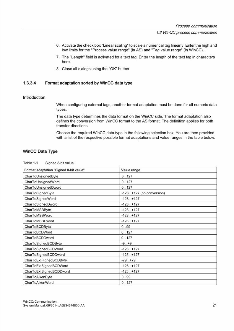
8/20/2019 WinCC Communication en-US en-US
http://slidepdf.com/reader/full/wincc-communication-en-us-en-us 21/527
6. Activate the check box "Linear scaling" to scale a numerical tag linearly. Enter the high andlow limits for the "Process value range" (in AS) and "Tag value range" (in WinCC).
7. The "Length" field is activated for a text tag. Enter the length of the text tag in charactershere.
8. Close all dialogs using the "OK" button.
1.3.3.4 Format adaptation sorted by WinCC data type
Introduction
When configuring external tags, another format adaptation must be done for all numeric datatypes.
The data type determines the data format on the WinCC side. The format adaptation alsodefines the conversion from WinCC format to the AS format. The definition applies for bothtransfer directions.
Choose the required WinCC data type in the following selection box. You are then providedwith a list of the respective possible format adaptations and value ranges in the table below.
WinCC Data Type
Table 1-1 Signed 8-bit value
Format adaptation Signed 8-bit value Value range
CharToUnsignedByte 0...127
CharToUnsignedWord 0...127
CharToUnsignedDword 0...127
CharToSignedByte -128...+127 (no conversion)
CharToSignedWord -128...+127
CharToSignedDword -128...+127
CharToMSBByte -128...+127
CharToMSBWord -128...+127
CharToMSBDword -128...+127
CharToBCDByte 0...99
CharToBCDWord 0...127CharToBCDDword 0...127
CharToSignedBCDByte -9...+9
CharToSignedBCDWord -128...+127
CharToSignedBCDDword -128...+127
CharToExtSignedBCDByte -79...+79
CharToExtSignedBCDWord -128...+127
CharToExtSignedBCDDword -128...+127
CharToAikenByte 0...99
CharToAikenWord 0...127
Process communication
1.3 WinCC process communication
WinCC: CommunicationSystem Manual, 06/2014, A5E34374800-AA 21
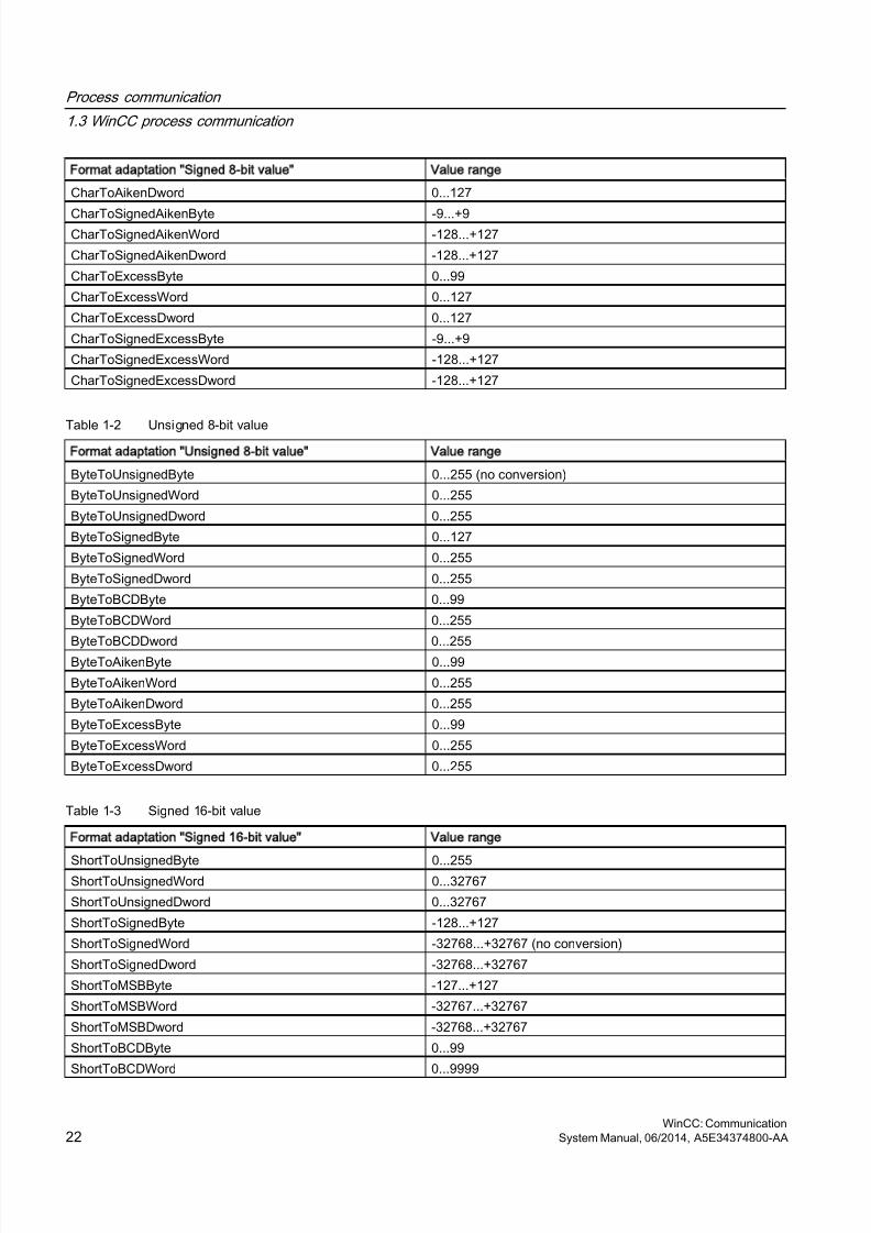
8/20/2019 WinCC Communication en-US en-US
http://slidepdf.com/reader/full/wincc-communication-en-us-en-us 22/527
Format adaptation Signed 8-bit value Value range
CharToAikenDword 0...127
CharToSignedAikenByte -9...+9CharToSignedAikenWord -128...+127
CharToSignedAikenDword -128...+127
CharToExcessByte 0...99
CharToExcessWord 0...127
CharToExcessDword 0...127
CharToSignedExcessByte -9...+9
CharToSignedExcessWord -128...+127
CharToSignedExcessDword -128...+127
Table 1-2 Unsigned 8-bit valueFormat adaptation Unsigned 8-bit value Value range
ByteToUnsignedByte 0...255 (no conversion)
ByteToUnsignedWord 0...255
ByteToUnsignedDword 0...255
ByteToSignedByte 0...127
ByteToSignedWord 0...255
ByteToSignedDword 0...255
ByteToBCDByte 0...99
ByteToBCDWord 0...255
ByteToBCDDword 0...255ByteToAikenByte 0...99
ByteToAikenWord 0...255
ByteToAikenDword 0...255
ByteToExcessByte 0...99
ByteToExcessWord 0...255
ByteToExcessDword 0...255
Table 1-3 Signed 16-bit value
Format adaptation Signed 16-bit value Value range
ShortToUnsignedByte 0...255ShortToUnsignedWord 0...32767
ShortToUnsignedDword 0...32767
ShortToSignedByte -128...+127
ShortToSignedWord -32768...+32767 (no conversion)
ShortToSignedDword -32768...+32767
ShortToMSBByte -127...+127
ShortToMSBWord -32767...+32767
ShortToMSBDword -32768...+32767
ShortToBCDByte 0...99
ShortToBCDWord 0...9999
Process communication
1.3 WinCC process communication
WinCC: Communication22 System Manual, 06/2014, A5E34374800-AA
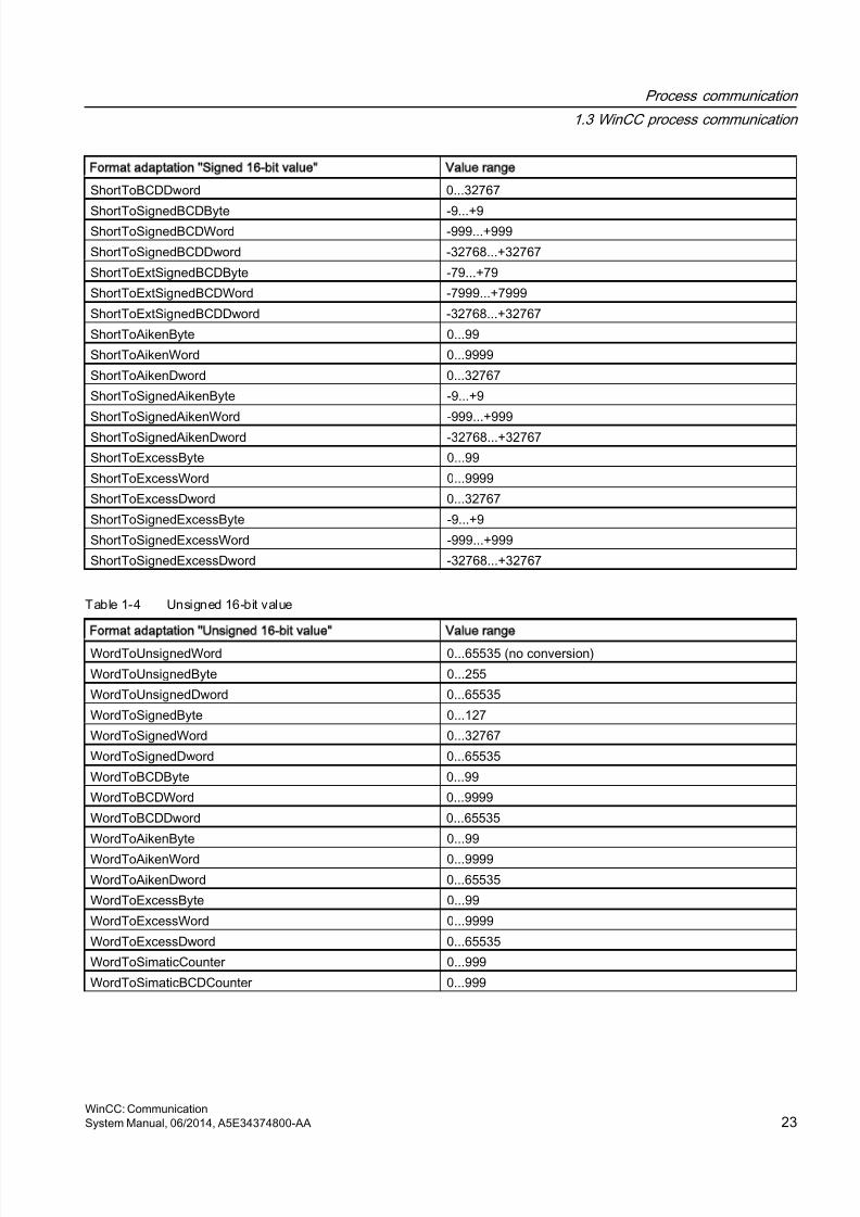
8/20/2019 WinCC Communication en-US en-US
http://slidepdf.com/reader/full/wincc-communication-en-us-en-us 23/527
Format adaptation Signed 16-bit value Value range
ShortToBCDDword 0...32767
ShortToSignedBCDByte -9...+9ShortToSignedBCDWord -999...+999
ShortToSignedBCDDword -32768...+32767
ShortToExtSignedBCDByte -79...+79
ShortToExtSignedBCDWord -7999...+7999
ShortToExtSignedBCDDword -32768...+32767
ShortToAikenByte 0...99
ShortToAikenWord 0...9999
ShortToAikenDword 0...32767
ShortToSignedAikenByte -9...+9
ShortToSignedAikenWord -999...+999
ShortToSignedAikenDword -32768...+32767
ShortToExcessByte 0...99
ShortToExcessWord 0...9999
ShortToExcessDword 0...32767
ShortToSignedExcessByte -9...+9
ShortToSignedExcessWord -999...+999
ShortToSignedExcessDword -32768...+32767
Table 1-4 Unsigned 16-bit value
Format adaptation Unsigned 16-bit value Value range
WordToUnsignedWord 0...65535 (no conversion)
WordToUnsignedByte 0...255
WordToUnsignedDword 0...65535
WordToSignedByte 0...127
WordToSignedWord 0...32767
WordToSignedDword 0...65535
WordToBCDByte 0...99
WordToBCDWord 0...9999
WordToBCDDword 0...65535
WordToAikenByte 0...99
WordToAikenWord 0...9999
WordToAikenDword 0...65535
WordToExcessByte 0...99
WordToExcessWord 0...9999
WordToExcessDword 0...65535
WordToSimaticCounter 0...999
WordToSimaticBCDCounter 0...999
Process communication
1.3 WinCC process communication
WinCC: CommunicationSystem Manual, 06/2014, A5E34374800-AA 23
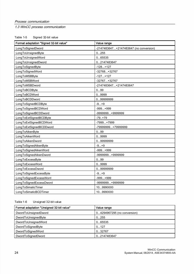
8/20/2019 WinCC Communication en-US en-US
http://slidepdf.com/reader/full/wincc-communication-en-us-en-us 24/527
Table 1-5 Signed 32-bit value
Format adaptation Signed 32-bit value Value range
LongToSignedDword -2147483647...+2147483647 (no conversion)LongToUnsignedByte 0...255
LongToUnsignedWord 0...65535
LongToUnsignedDword 0...2147483647
LongToSignedByte -128...+127
LongToSignedWord -32768...+32767
LongToMSBByte -127...+127
LongToMSBWord -32767...+32767
LongToMSBDword -2147483647...+2147483647
LongToBCDByte 0...99
LongToBCDWord 0...9999LongToBCDDword 0...99999999
LongToSignedBCDByte -9...+9
LongToSignedBCDWord -999...+999
LongToSignedBCDDword -9999999...+9999999
LongToExtSignedBCDByte -79..+79
LongToExtSignedBCDWord -7999...+7999
LongToExtSignedBCDDword -79999999...+79999999
LongToAikenByte 0...99
LongToAikenWord 0...9999
LongToAikenDword 0...99999999
LongToSignedAikenByte -9...+9
LongToSignedAikenWord -999...+999
LongToSignedAikenDword -9999999...+9999999
LongToExcessByte 0...99
LongToExcessWord 0...9999
LongToExcessDword 0...99999999
LongToSignedExcessByte -9...+9
LongToSignedExcessWord -999...+999
LongToSignedExcessDword -9999999...+9999999
LongToSimaticTimer 10...9990000
LongToSimaticBCDTimer 10...9990000
Table 1-6 Unsigned 32-bit value
Format adaptation Unsigned 32-bit value Value range
DwordToUnsignedDword 0...4294967295 (no conversion)
DwordToUnsignedByte 0...255
DwordToUnsignedWord 0...65535
DwordToSignedByte 0...127
DwordToSignedWord 0...32767
DwordToSignedDword 0...2147483647
Process communication
1.3 WinCC process communication
WinCC: Communication24 System Manual, 06/2014, A5E34374800-AA
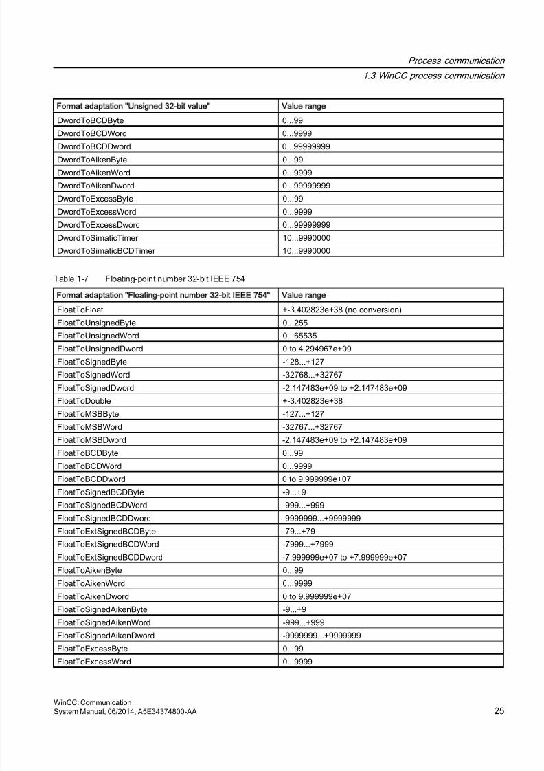
8/20/2019 WinCC Communication en-US en-US
http://slidepdf.com/reader/full/wincc-communication-en-us-en-us 25/527
Format adaptation Unsigned 32-bit value Value range
DwordToBCDByte 0...99
DwordToBCDWord 0...9999DwordToBCDDword 0...99999999
DwordToAikenByte 0...99
DwordToAikenWord 0...9999
DwordToAikenDword 0...99999999
DwordToExcessByte 0...99
DwordToExcessWord 0...9999
DwordToExcessDword 0...99999999
DwordToSimaticTimer 10...9990000
DwordToSimaticBCDTimer 10...9990000
Table 1-7 Floating-point number 32-bit IEEE 754
Format adaptation Floating-point number 32-bit IEEE 754 Value range
FloatToFloat +-3.402823e+38 (no conversion)
FloatToUnsignedByte 0...255
FloatToUnsignedWord 0...65535
FloatToUnsignedDword 0 to 4.294967e+09
FloatToSignedByte -128...+127
FloatToSignedWord -32768...+32767
FloatToSignedDword -2.147483e+09 to +2.147483e+09
FloatToDouble +-3.402823e+38FloatToMSBByte -127...+127
FloatToMSBWord -32767...+32767
FloatToMSBDword -2.147483e+09 to +2.147483e+09
FloatToBCDByte 0...99
FloatToBCDWord 0...9999
FloatToBCDDword 0 to 9.999999e+07
FloatToSignedBCDByte -9...+9
FloatToSignedBCDWord -999...+999
FloatToSignedBCDDword -9999999...+9999999
FloatToExtSignedBCDByte -79...+79
FloatToExtSignedBCDWord -7999...+7999
FloatToExtSignedBCDDword -7.999999e+07 to +7.999999e+07
FloatToAikenByte 0...99
FloatToAikenWord 0...9999
FloatToAikenDword 0 to 9.999999e+07
FloatToSignedAikenByte -9...+9
FloatToSignedAikenWord -999...+999
FloatToSignedAikenDword -9999999...+9999999
FloatToExcessByte 0...99
FloatToExcessWord 0...9999
Process communication
1.3 WinCC process communication
WinCC: CommunicationSystem Manual, 06/2014, A5E34374800-AA 25

8/20/2019 WinCC Communication en-US en-US
http://slidepdf.com/reader/full/wincc-communication-en-us-en-us 26/527
Format adaptation Floating-point number 32-bit IEEE 754 Value range
FloatToExcessDword 0 to 9.999999e+07
FloatToSignedExcessByte -9...+9FloatToSignedExcessWord -999...+999
FloatToSignedExcessDword -9999999...+9999999
FloatToS5Timer 10...9990000
FloatToS5Float +-1.701411e+38
Table 1-8 Floating-point number 64-bit IEEE 754
Format adaptation Floating-point number 64-bit IEEE 754 Value range
DoubleToDouble +-1.79769313486231e+308 (no conversion)
DoubleToUnsignedByte 0...255
DoubleToUnsignedWord 0...65535DoubleToUnsignedDword 0...4294967295
DoubleToSignedByte -128...+127
DoubleToSignedWord -32768...+32767
DoubleToSignedDword -2147483647...+2147483647
DoubleToFloat +-3.402823e+38
DoubleToMSBByte -127...+127
DoubleToMSBWord -32767...+32767
DoubleToMSBDword -2147483647...+2147483647
DoubleToBCDByte 0...99
DoubleToBCDWord 0...9999DoubleToBCDDword 0...99999999
DoubleToSignedBCDByte -9...+9
DoubleToSignedBCDWord -999...+999
DoubleToSignedBCDDword -9999999...+9999999
DoubleToExtSignedBCDByte -79...+79
DoubleToExtSignedBCDWord -7999...+7999
DoubleToExtSignedBCDDword -79999999...+79999999
DoubleToAikenByte 0...99
DoubleToAikenWord 0...9999
DoubleToAikenDword 0...99999999
DoubleToSignedAikenByte -9...+9
DoubleToSignedAikenWord -999...+999
DoubleToSignedAikenDword -9999999...+9999999
DoubleToExcessByte 0...99
DoubleToExcessWord 0...9999
DoubleToExcessDword 0...99999999
DoubleToSignedExcessByte -9...+9
DoubleToSignedExcessWord -999...+999
DoubleToSignedExcessDword -9999999...+9999999
Process communication
1.3 WinCC process communication
WinCC: Communication26 System Manual, 06/2014, A5E34374800-AA
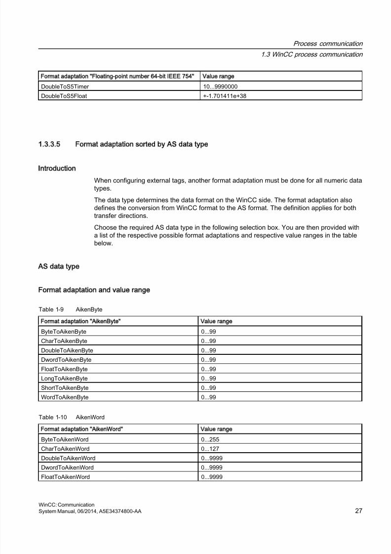
8/20/2019 WinCC Communication en-US en-US
http://slidepdf.com/reader/full/wincc-communication-en-us-en-us 27/527
Format adaptation Floating-point number 64-bit IEEE 754 Value range
DoubleToS5Timer 10...9990000
DoubleToS5Float +-1.701411e+38
1.3.3.5 Format adaptation sorted by AS data type
Introduction
When configuring external tags, another format adaptation must be done for all numeric datatypes.
The data type determines the data format on the WinCC side. The format adaptation alsodefines the conversion from WinCC format to the AS format. The definition applies for bothtransfer directions.
Choose the required AS data type in the following selection box. You are then provided witha list of the respective possible format adaptations and respective value ranges in the tablebelow.
AS data type
Format adaptation and value range
Table 1-9 AikenByte
Format adaptation AikenByte Value range
ByteToAikenByte 0...99
CharToAikenByte 0...99
DoubleToAikenByte 0...99
DwordToAikenByte 0...99
FloatToAikenByte 0...99
LongToAikenByte 0...99
ShortToAikenByte 0...99WordToAikenByte 0...99
Table 1-10 AikenWord
Format adaptation AikenWord Value range
ByteToAikenWord 0...255
CharToAikenWord 0...127
DoubleToAikenWord 0...9999
DwordToAikenWord 0...9999
FloatToAikenWord 0...9999
Process communication
1.3 WinCC process communication
WinCC: CommunicationSystem Manual, 06/2014, A5E34374800-AA 27

8/20/2019 WinCC Communication en-US en-US
http://slidepdf.com/reader/full/wincc-communication-en-us-en-us 28/527
Format adaptation AikenWord Value range
LongToAikenWord 0...9999
ShortToAikenWord 0...9999WordToAikenWord 0...9999
Table 1-11 AikenDWord
Format adaptation AikenDWord Value range
ByteToAikenDword 0...255
CharToAikenDword 0...127
DoubleToAikenDword 0...99999999
DwordToAikenDword 0...99999999
FloatToAikenDword 0 to 9.999999e+07
LongToAikenDword 0...99999999ShortToAikenDword 0...32767
WordToAikenDword 0...65535
Table 1-12 BCDByte
Format adaptation BCDByte Value range
ByteToBCDByte 0...99
CharToBCDByte 0...99
DoubleToBCDByte 0...99
DwordToBCDByte 0...99
FloatToBCDByte 0...99LongToBCDByte 0...99
ShortToBCDByte 0...99
WordToBCDByte 0...99
Table 1-13 BCDWord
Format adaptation BCDWord Value range
ByteToBCDWord 0...255
CharToBCDWord 0...127
DoubleToBCDWord 0...9999
DwordToBCDWord 0...9999
FloatToBCDWord 0...9999
LongToBCDWord 0...9999
ShortToBCDWord 0...9999
WordToBCDWord 0...9999
Table 1-14 BCDDWord
Format adaptation BCDDWord Value range
ByteToBCDDword 0...255
CharToBCDDword 0...127
Process communication
1.3 WinCC process communication
WinCC: Communication28 System Manual, 06/2014, A5E34374800-AA
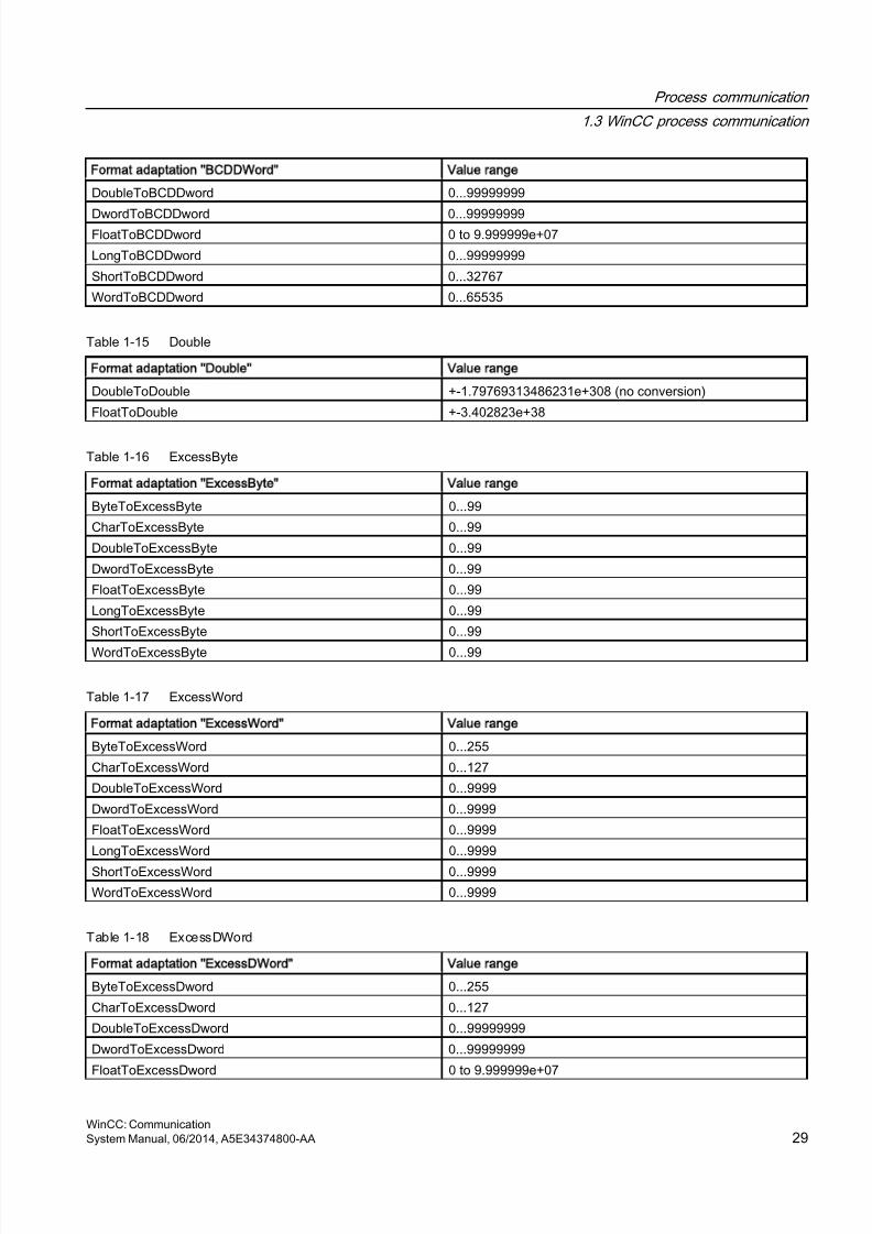
8/20/2019 WinCC Communication en-US en-US
http://slidepdf.com/reader/full/wincc-communication-en-us-en-us 29/527
Format adaptation BCDDWord Value range
DoubleToBCDDword 0...99999999
DwordToBCDDword 0...99999999FloatToBCDDword 0 to 9.999999e+07
LongToBCDDword 0...99999999
ShortToBCDDword 0...32767
WordToBCDDword 0...65535
Table 1-15 Double
Format adaptation Double Value range
DoubleToDouble +-1.79769313486231e+308 (no conversion)
FloatToDouble +-3.402823e+38
Table 1-16 ExcessByte
Format adaptation ExcessByte Value range
ByteToExcessByte 0...99
CharToExcessByte 0...99
DoubleToExcessByte 0...99
DwordToExcessByte 0...99
FloatToExcessByte 0...99
LongToExcessByte 0...99
ShortToExcessByte 0...99
WordToExcessByte 0...99
Table 1-17 ExcessWord
Format adaptation ExcessWord Value range
ByteToExcessWord 0...255
CharToExcessWord 0...127
DoubleToExcessWord 0...9999
DwordToExcessWord 0...9999
FloatToExcessWord 0...9999
LongToExcessWord 0...9999
ShortToExcessWord 0...9999
WordToExcessWord 0...9999
Table 1-18 ExcessDWord
Format adaptation ExcessDWord Value range
ByteToExcessDword 0...255
CharToExcessDword 0...127
DoubleToExcessDword 0...99999999
DwordToExcessDword 0...99999999
FloatToExcessDword 0 to 9.999999e+07
Process communication
1.3 WinCC process communication
WinCC: CommunicationSystem Manual, 06/2014, A5E34374800-AA 29
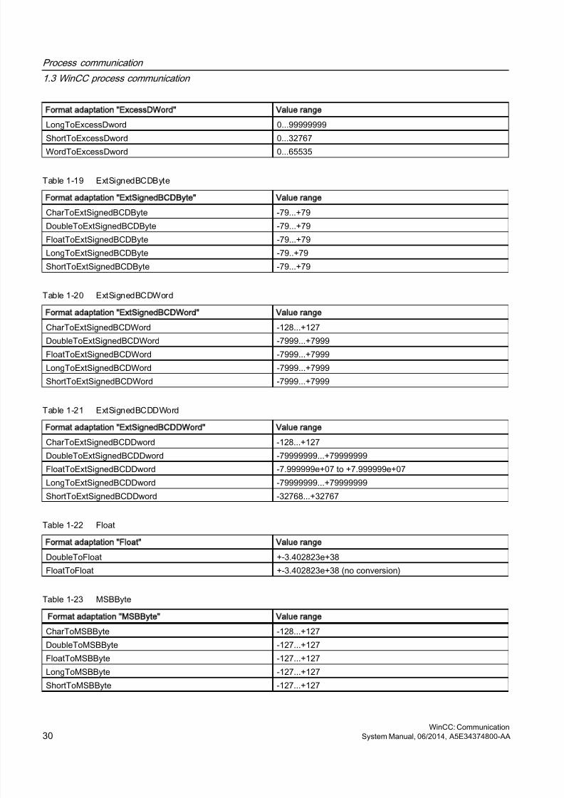
8/20/2019 WinCC Communication en-US en-US
http://slidepdf.com/reader/full/wincc-communication-en-us-en-us 30/527
Format adaptation ExcessDWord Value range
LongToExcessDword 0...99999999
ShortToExcessDword 0...32767WordToExcessDword 0...65535
Table 1-19 ExtSignedBCDByte
Format adaptation ExtSignedBCDByte Value range
CharToExtSignedBCDByte -79...+79
DoubleToExtSignedBCDByte -79...+79
FloatToExtSignedBCDByte -79...+79
LongToExtSignedBCDByte -79..+79
ShortToExtSignedBCDByte -79...+79
Table 1-20 ExtSignedBCDWord
Format adaptation ExtSignedBCDWord Value range
CharToExtSignedBCDWord -128...+127
DoubleToExtSignedBCDWord -7999...+7999
FloatToExtSignedBCDWord -7999...+7999
LongToExtSignedBCDWord -7999...+7999
ShortToExtSignedBCDWord -7999...+7999
Table 1-21 ExtSignedBCDDWord
Format adaptation ExtSignedBCDDWord Value range
CharToExtSignedBCDDword -128...+127
DoubleToExtSignedBCDDword -79999999...+79999999
FloatToExtSignedBCDDword -7.999999e+07 to +7.999999e+07
LongToExtSignedBCDDword -79999999...+79999999
ShortToExtSignedBCDDword -32768...+32767
Table 1-22 Float
Format adaptation Float Value range
DoubleToFloat +-3.402823e+38FloatToFloat +-3.402823e+38 (no conversion)
Table 1-23 MSBByte
Format adaptation MSBByte Value range
CharToMSBByte -128...+127
DoubleToMSBByte -127...+127
FloatToMSBByte -127...+127
LongToMSBByte -127...+127
ShortToMSBByte -127...+127
Process communication
1.3 WinCC process communication
WinCC: Communication30 System Manual, 06/2014, A5E34374800-AA
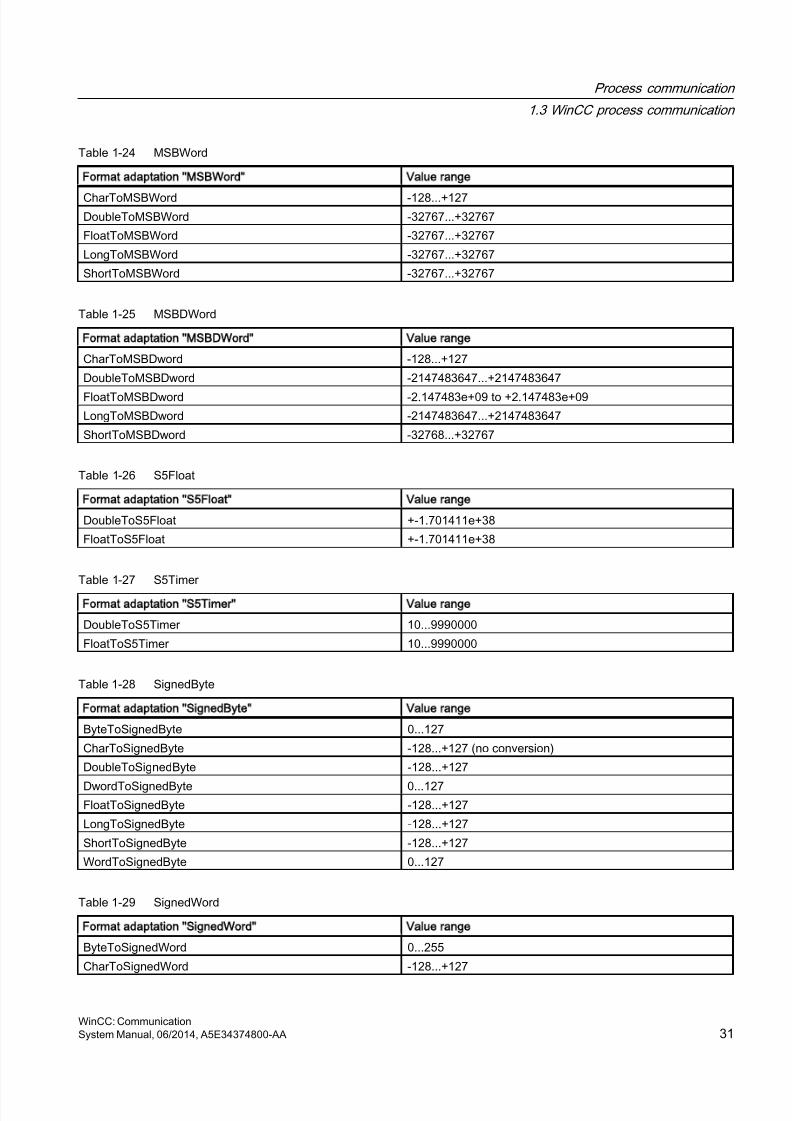
8/20/2019 WinCC Communication en-US en-US
http://slidepdf.com/reader/full/wincc-communication-en-us-en-us 31/527
Table 1-24 MSBWord
Format adaptation MSBWord Value range
CharToMSBWord -128...+127DoubleToMSBWord -32767...+32767
FloatToMSBWord -32767...+32767
LongToMSBWord -32767...+32767
ShortToMSBWord -32767...+32767
Table 1-25 MSBDWord
Format adaptation MSBDWord Value range
CharToMSBDword -128...+127
DoubleToMSBDword -2147483647...+2147483647
FloatToMSBDword -2.147483e+09 to +2.147483e+09
LongToMSBDword -2147483647...+2147483647
ShortToMSBDword -32768...+32767
Table 1-26 S5Float
Format adaptation S5Float Value range
DoubleToS5Float +-1.701411e+38
FloatToS5Float +-1.701411e+38
Table 1-27 S5Timer
Format adaptation S5Timer Value range
DoubleToS5Timer 10...9990000
FloatToS5Timer 10...9990000
Table 1-28 SignedByte
Format adaptation SignedByte Value range
ByteToSignedByte 0...127
CharToSignedByte -128...+127 (no conversion)
DoubleToSignedByte -128...+127
DwordToSignedByte 0...127FloatToSignedByte -128...+127
LongToSignedByte -128...+127
ShortToSignedByte -128...+127
WordToSignedByte 0...127
Table 1-29 SignedWord
Format adaptation SignedWord Value range
ByteToSignedWord 0...255
CharToSignedWord -128...+127
Process communication
1.3 WinCC process communication
WinCC: CommunicationSystem Manual, 06/2014, A5E34374800-AA 31
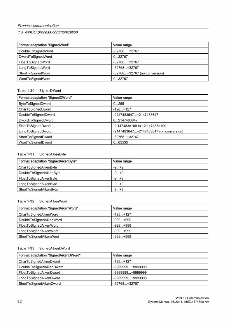
8/20/2019 WinCC Communication en-US en-US
http://slidepdf.com/reader/full/wincc-communication-en-us-en-us 32/527
Format adaptation SignedWord Value range
DoubleToSignedWord -32768...+32767
DwordToSignedWord 0...32767FloatToSignedWord -32768...+32767
LongToSignedWord -32768...+32767
ShortToSignedWord -32768...+32767 (no conversion)
WordToSignedWord 0...32767
Table 1-30 SignedDWord
Format adaptation SignedDWord Value range
ByteToSignedDword 0...255
CharToSignedDword -128...+127
DoubleToSignedDword -2147483647...+2147483647DwordToSignedDword 0...2147483647
FloatToSignedDword -2.147483e+09 to +2.147483e+09
LongToSignedDword -2147483647...+2147483647 (no conversion)
ShortToSignedDword -32768...+32767
WordToSignedDword 0...65535
Table 1-31 SignedAikenByte
Format adaptation SignedAikenByte Value range
CharToSignedAikenByte -9...+9
DoubleToSignedAikenByte -9...+9FloatToSignedAikenByte -9...+9
LongToSignedAikenByte -9...+9
ShortToSignedAikenByte -9...+9
Table 1-32 SignedAikenWord
Format adaptation SignedAikenWord Value range
CharToSignedAikenWord -128...+127
DoubleToSignedAikenWord -999...+999
FloatToSignedAikenWord -999...+999
LongToSignedAikenWord -999...+999
ShortToSignedAikenWord -999...+999
Table 1-33 SignedAikenDWord
Format adaptation SignedAikenDWord Value range
CharToSignedAikenDword -128...+127
DoubleToSignedAikenDword -9999999...+9999999
FloatToSignedAikenDword -9999999...+9999999
LongToSignedAikenDword -9999999...+9999999
ShortToSignedAikenDword -32768...+32767
Process communication
1.3 WinCC process communication
WinCC: Communication32 System Manual, 06/2014, A5E34374800-AA
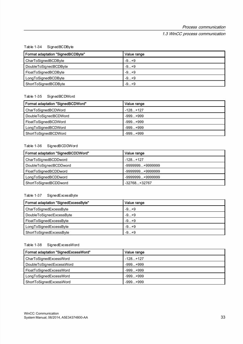
8/20/2019 WinCC Communication en-US en-US
http://slidepdf.com/reader/full/wincc-communication-en-us-en-us 33/527
Table 1-34 SignedBCDByte
Format adaptation SignedBCDByte Value range
CharToSignedBCDByte -9...+9DoubleToSignedBCDByte -9...+9
FloatToSignedBCDByte -9...+9
LongToSignedBCDByte -9...+9
ShortToSignedBCDByte -9...+9
Table 1-35 SignedBCDWord
Format adaptation SignedBCDWord Value range
CharToSignedBCDWord -128...+127
DoubleToSignedBCDWord -999...+999
FloatToSignedBCDWord -999...+999
LongToSignedBCDWord -999...+999
ShortToSignedBCDWord -999...+999
Table 1-36 SignedBCDDWord
Format adaptation SignedBCDDWord Value range
CharToSignedBCDDword -128...+127
DoubleToSignedBCDDword -9999999...+9999999
FloatToSignedBCDDword -9999999...+9999999
LongToSignedBCDDword -9999999...+9999999
ShortToSignedBCDDword -32768...+32767
Table 1-37 SignedExcessByte
Format adaptation SignedExcessByte Value range
CharToSignedExcessByte -9...+9
DoubleToSignedExcessByte -9...+9
FloatToSignedExcessByte -9...+9
LongToSignedExcessByte -9...+9
ShortToSignedExcessByte -9...+9
Table 1-38 SignedExcessWord
Format adaptation SignedExcessWord Value range
CharToSignedExcessWord -128...+127
DoubleToSignedExcessWord -999...+999
FloatToSignedExcessWord -999...+999
LongToSignedExcessWord -999...+999
ShortToSignedExcessWord -999...+999
Process communication
1.3 WinCC process communication
WinCC: CommunicationSystem Manual, 06/2014, A5E34374800-AA 33
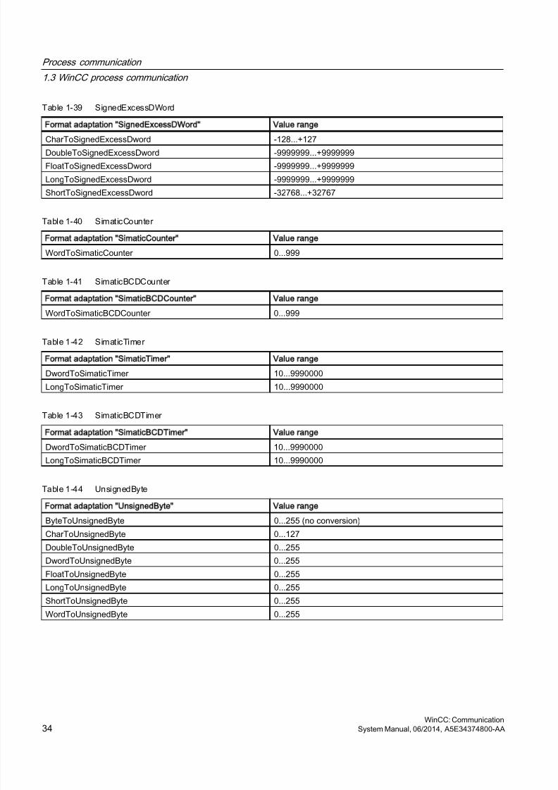
8/20/2019 WinCC Communication en-US en-US
http://slidepdf.com/reader/full/wincc-communication-en-us-en-us 34/527
Table 1-39 SignedExcessDWord
Format adaptation SignedExcessDWord Value range
CharToSignedExcessDword -128...+127DoubleToSignedExcessDword -9999999...+9999999
FloatToSignedExcessDword -9999999...+9999999
LongToSignedExcessDword -9999999...+9999999
ShortToSignedExcessDword -32768...+32767
Table 1-40 SimaticCounter
Format adaptation SimaticCounter Value range
WordToSimaticCounter 0...999
Table 1-41 SimaticBCDCounter
Format adaptation SimaticBCDCounter Value range
WordToSimaticBCDCounter 0...999
Table 1-42 SimaticTimer
Format adaptation SimaticTimer Value range
DwordToSimaticTimer 10...9990000
LongToSimaticTimer 10...9990000
Table 1-43 SimaticBCDTimer
Format adaptation SimaticBCDTimer Value range
DwordToSimaticBCDTimer 10...9990000
LongToSimaticBCDTimer 10...9990000
Table 1-44 UnsignedByte
Format adaptation UnsignedByte Value range
ByteToUnsignedByte 0...255 (no conversion)
CharToUnsignedByte 0...127
DoubleToUnsignedByte 0...255
DwordToUnsignedByte 0...255
FloatToUnsignedByte 0...255
LongToUnsignedByte 0...255
ShortToUnsignedByte 0...255
WordToUnsignedByte 0...255
Process communication
1.3 WinCC process communication
WinCC: Communication34 System Manual, 06/2014, A5E34374800-AA
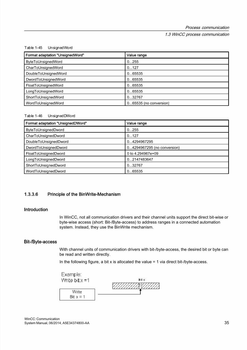
8/20/2019 WinCC Communication en-US en-US
http://slidepdf.com/reader/full/wincc-communication-en-us-en-us 35/527
Table 1-45 UnsignedWord
Format adaptation UnsignedWord Value range
ByteToUnsignedWord 0...255CharToUnsignedWord 0...127
DoubleToUnsignedWord 0...65535
DwordToUnsignedWord 0...65535
FloatToUnsignedWord 0...65535
LongToUnsignedWord 0...65535
ShortToUnsignedWord 0...32767
WordToUnsignedWord 0...65535 (no conversion)
Table 1-46 UnsignedDWord
Format adaptation UnsignedDWord Value range
ByteToUnsignedDword 0...255
CharToUnsignedDword 0...127
DoubleToUnsignedDword 0...4294967295
DwordToUnsignedDword 0...4294967295 (no conversion)
FloatToUnsignedDword 0 to 4.294967e+09
LongToUnsignedDword 0...2147483647
ShortToUnsignedDword 0...32767
WordToUnsignedDword 0...65535
1.3.3.6 Principle of the BinWrite-Mechanism
Introduction
In WinCC, not all communication drivers and their channel units support the direct bit-wise orbyte-wise access (short: Bit-/Byte-access) to address ranges in a connected automationsystem. Instead, they use the BinWrite mechanism.
Bit-/Byte-access
With channel units of communication drivers with bit-/byte-access, the desired bit or byte canbe read and written directly.
In the following figure, a bit x is allocated the value = 1 via direct bit-/byte-access.
Process communication
1.3 WinCC process communication
WinCC: CommunicationSystem Manual, 06/2014, A5E34374800-AA 35
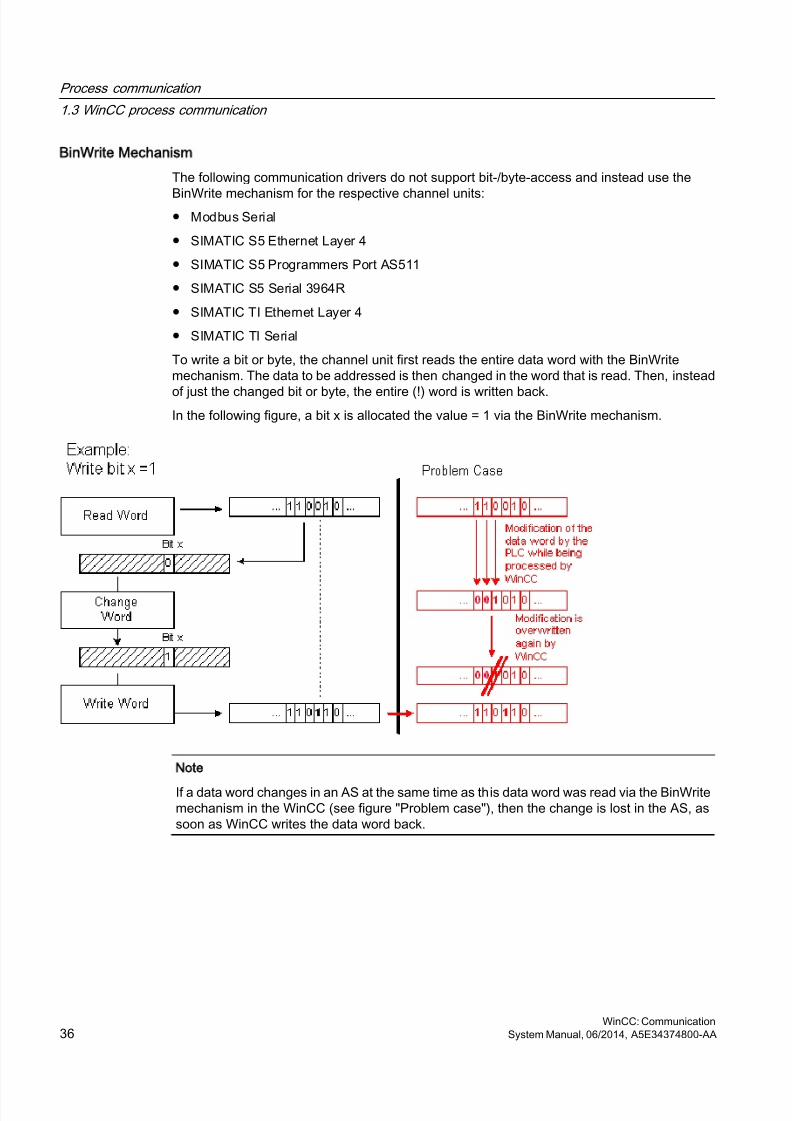
8/20/2019 WinCC Communication en-US en-US
http://slidepdf.com/reader/full/wincc-communication-en-us-en-us 36/527
BinWrite Mechanism
The following communication drivers do not support bit-/byte-access and instead use the
BinWrite mechanism for the respective channel units:● Modbus Serial
● SIMATIC S5 Ethernet Layer 4
● SIMATIC S5 Programmers Port AS511
● SIMATIC S5 Serial 3964R
● SIMATIC TI Ethernet Layer 4
● SIMATIC TI Serial
To write a bit or byte, the channel unit first reads the entire data word with the BinWritemechanism. The data to be addressed is then changed in the word that is read. Then, instead
of just the changed bit or byte, the entire (!) word is written back.In the following figure, a bit x is allocated the value = 1 via the BinWrite mechanism.
Note
If a data word changes in an AS at the same time as this data word was read via the BinWritemechanism in the WinCC (see figure "Problem case"), then the change is lost in the AS, assoon as WinCC writes the data word back.
Process communication
1.3 WinCC process communication
WinCC: Communication36 System Manual, 06/2014, A5E34374800-AA
8/20/2019 WinCC Communication en-US en-US
http://slidepdf.com/reader/full/wincc-communication-en-us-en-us 37/527
1.3.3.7 How to Configure a Tag with BinWrite
Introduction
If you want to configure a "Binary tag" for the channel unit of a communication driver, whichdoes not support bit-/byte-access, you have to activate and configure the BinWrite mechanismusing a dialog, which otherwise does not exist.
Requirements
● The required communication processor and the hardware driver are installed.
● The desired communication driver, which does not support bit-/byte-access however, isinstalled, e.g. "SIMATIC S5 Ethernet Layer 4".
● A connection has already been created based on its channel units.
Procedure
1. Select the connection for which a tag is to be configured.
2. Click the "Tags" tab below the table area.
3. Click in the top free cell of the "Name" column.Enter the name for the tag.
4. Select "Binary tag", "Unsigned 8 bit value" or "Signed 8 bit value" as data type.
Process communication
1.3 WinCC process communication
WinCC: CommunicationSystem Manual, 06/2014, A5E34374800-AA 37
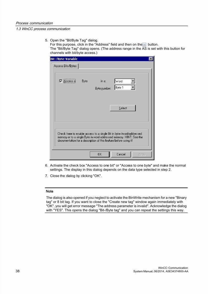
8/20/2019 WinCC Communication en-US en-US
http://slidepdf.com/reader/full/wincc-communication-en-us-en-us 38/527
5. Open the "Bit/Byte Tag" dialog.For this purpose, click in the "Address" field and then on the button.The "Bit/Byte Tag" dialog opens. (The address range in the AS is set with this button for
channels with bit/byte access.)
6. Activate the check box "Access to one bit" or "Access to one byte" and make the normalsettings. The display in this dialog depends on the data type selected in step 2.
7. Close the dialog by clicking "OK".
Note
The dialog is also opened if you neglect to activate the BinWrite mechanism for a new "Binarytag" or 8 bit tag. If you want to close the "Create new tag" window again immediately with
"OK", you will get error message "The address parameter is invalid". Acknowledge the dialogwith "YES". This opens the dialog "Bit-/Byte tag" and you can repeat the settings this way.
Process communication
1.3 WinCC process communication
WinCC: Communication38 System Manual, 06/2014, A5E34374800-AA
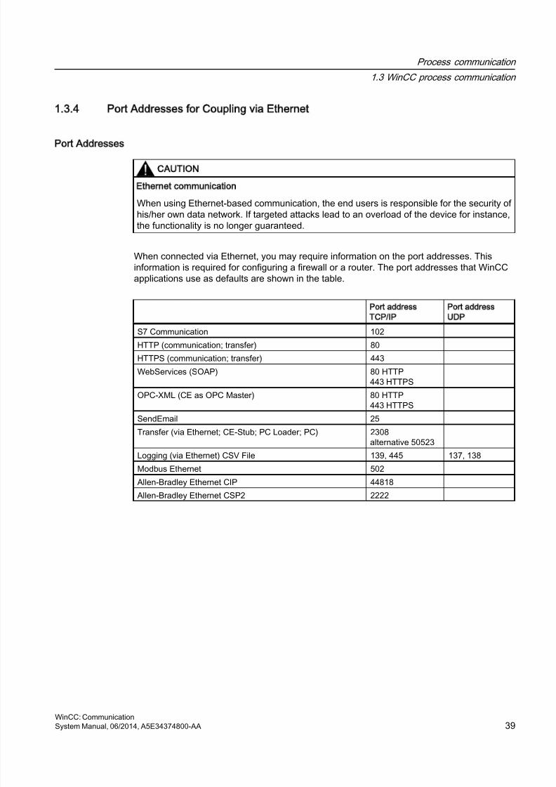
8/20/2019 WinCC Communication en-US en-US
http://slidepdf.com/reader/full/wincc-communication-en-us-en-us 39/527
1.3.4 Port Addresses for Coupling via Ethernet
Port Addresses
CAUTION
Ethernet communication
When using Ethernet-based communication, the end users is responsible for the security ofhis/her own data network. If targeted attacks lead to an overload of the device for instance,the functionality is no longer guaranteed.
When connected via Ethernet, you may require information on the port addresses. Thisinformation is required for configuring a firewall or a router. The port addresses that WinCC
applications use as defaults are shown in the table.
Port address
TCP/IP
Port address
UDP
S7 Communication 102
HTTP (communication; transfer) 80
HTTPS (communication; transfer) 443
WebServices (SOAP) 80 HTTP443 HTTPS
OPC-XML (CE as OPC Master) 80 HTTP443 HTTPS
SendEmail 25
Transfer (via Ethernet; CE-Stub; PC Loader; PC) 2308alternative 50523
Logging (via Ethernet) CSV File 139, 445 137, 138
Modbus Ethernet 502
Allen-Bradley Ethernet CIP 44818
Allen-Bradley Ethernet CSP2 2222
Process communication
1.3 WinCC process communication
WinCC: CommunicationSystem Manual, 06/2014, A5E34374800-AA 39

8/20/2019 WinCC Communication en-US en-US
http://slidepdf.com/reader/full/wincc-communication-en-us-en-us 40/527
8/20/2019 WinCC Communication en-US en-US
http://slidepdf.com/reader/full/wincc-communication-en-us-en-us 41/527
Allen Bradley - Ethernet IP
2
2.1 WinCC Channel Allen Bradley - Ethernet IP
Introduction
The channel "Allen Bradley - Ethernet IP" is used for linking to Allen-Bradley automationsystems. The communication is handled with the Ethernet IP protocol.
Depending on the communication hardware used, the system supports connections via thefollowing channel units:
● Allen Bradley E/IP PLC5
● Allen Bradley E/IP SLC50x
● Allen Bradley E/IP ControlLogix
WinCC: CommunicationSystem Manual, 06/2014, A5E34374800-AA 41

8/20/2019 WinCC Communication en-US en-US
http://slidepdf.com/reader/full/wincc-communication-en-us-en-us 42/527
2.2 Channel Unit Assignment
Introduction
The channel unit must be selected for the channel in order to create a connection from WinCCto an existing or planned network.
Channel Unit Assignment
The following table shows an allocation of the channel units of channel "Allen Bradley - EthernetIP" to the network and automation system (AS).
Channel Unit of the Channel Communication Network AS
Allen Bradley E/IP PLC5 Ethernet IP PLC-5 with Ethernet PortAllen Bradley E/IP SLC50x Ethernet IP SLC 500 with Ethernet Port, e.g.
SLC 5/05
Allen Bradley E/IP ControlLogix Ethernet IP ControlLogix 5500
Allen Bradley - Ethernet IP
2.2 Channel Unit Assignment
WinCC: Communication42 System Manual, 06/2014, A5E34374800-AA
8/20/2019 WinCC Communication en-US en-US
http://slidepdf.com/reader/full/wincc-communication-en-us-en-us 43/527
2.3 Supported Data Types
Introduction
Define the required tags for a logical connection. The following data types are supported bythe "Allen Bradley - Ethernet IP" channel:
● Binary Tag
● Signed 8-bit value
● Unsigned 8-bit value
● Signed 16-bit value
● Unsigned 16-bit value
● Signed 32-bit value● Unsigned 32-bit value
● Floating-point number 32-bit IEEE 754
● Floating-point number 64-bit IEEE 754
● Text tag 8-bit character set
● Text tag 16-bit character set
Allen Bradley - Ethernet IP
2.3 Supported Data Types
WinCC: CommunicationSystem Manual, 06/2014, A5E34374800-AA 43
8/20/2019 WinCC Communication en-US en-US
http://slidepdf.com/reader/full/wincc-communication-en-us-en-us 44/527
2.4 Configuring the Channel
2.4.1 Configuring the Channel Allen Bradley - Ethernet IP
Introduction
WinCC needs a logical connection for communication of WinCC with the automation system(AS). This section shows how the "Allen Bradley - Ethernet IP" channel is configured.
When implementing the TCP/IP protocol, you must define the IP address of the AS for thelogic connection. The IP address consists of four numerical values, separated by dots. Thenumerical values must be within the range of 0-255.
Note
Timeout Behavior
Interrupted connections are not detected immediately when using the TCP/IP protocol. Thecheck-back message can take up to a minute.
Connectable controllers
Connections can be implemented for the following Allen-Bradley PLCs:
● Allen-Bradley ControlLogix 5500
● Allen-Bradley CompactLogix 5300
● PLC-5 with Ethernet Port
● SLC 500 with Ethernet Port, e.g. SLC 5/05
● MicroLogix
Released communication types
The following types of communication are system-tested and released for the "Allen Bradley- Ethernet IP" channel:
● Point-to-point connection:● Multiple point connection from the WinCC station with an optional amount of controllers.
Online Configuration
The online configuration of the "Allen Bradley - Ethernet IP" channel is not supported.
Allen Bradley - Ethernet IP
2.4 Configuring the Channel
WinCC: Communication44 System Manual, 06/2014, A5E34374800-AA
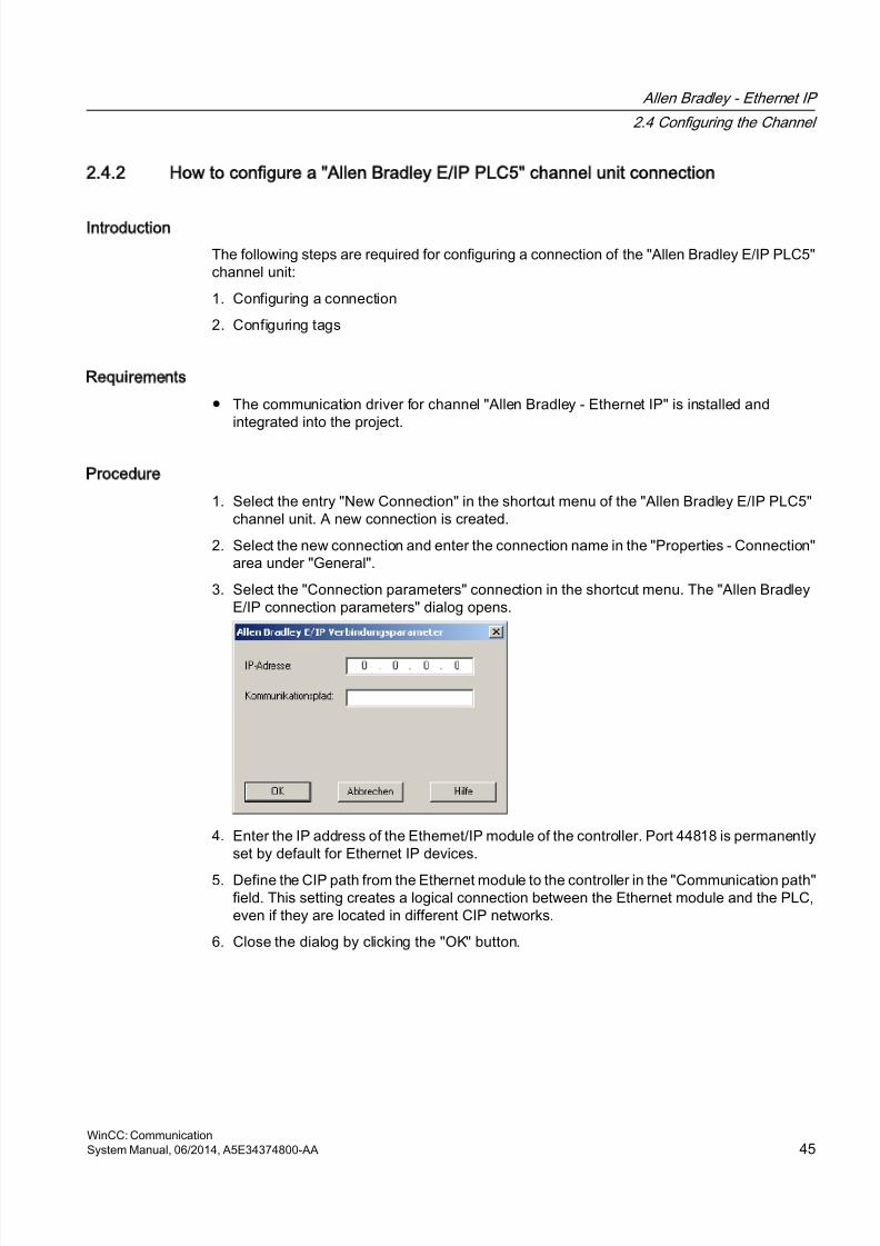
8/20/2019 WinCC Communication en-US en-US
http://slidepdf.com/reader/full/wincc-communication-en-us-en-us 45/527
2.4.2 How to configure a Allen Bradley E/IP PLC5 channel unit connection
Introduction
The following steps are required for configuring a connection of the "Allen Bradley E/IP PLC5"channel unit:
1. Configuring a connection
2. Configuring tags
Requirements
● The communication driver for channel "Allen Bradley - Ethernet IP" is installed andintegrated into the project.
Procedure
1. Select the entry "New Connection" in the shortcut menu of the "Allen Bradley E/IP PLC5"channel unit. A new connection is created.
2. Select the new connection and enter the connection name in the "Properties - Connection"area under "General".
3. Select the "Connection parameters" connection in the shortcut menu. The "Allen BradleyE/IP connection parameters" dialog opens.
4. Enter the IP address of the Ethernet/IP module of the controller. Port 44818 is permanentlyset by default for Ethernet IP devices.
5. Define the CIP path from the Ethernet module to the controller in the "Communication path"field. This setting creates a logical connection between the Ethernet module and the PLC,even if they are located in different CIP networks.
6. Close the dialog by clicking the "OK" button.
Allen Bradley - Ethernet IP
2.4 Configuring the Channel
WinCC: CommunicationSystem Manual, 06/2014, A5E34374800-AA 45
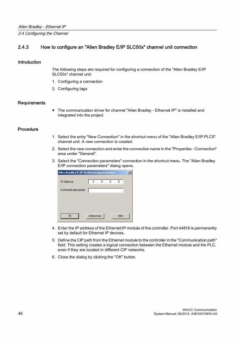
8/20/2019 WinCC Communication en-US en-US
http://slidepdf.com/reader/full/wincc-communication-en-us-en-us 46/527
2.4.3 How to configure an Allen Bradley E/IP SLC50x channel unit connection
Introduction
The following steps are required for configuring a connection of the "Allen Bradley E/IPSLC50x" channel unit:
1. Configuring a connection
2. Configuring tags
Requirements
● The communication driver for channel "Allen Bradley - Ethernet IP" is installed andintegrated into the project.
Procedure
1. Select the entry "New Connection" in the shortcut menu of the "Allen Bradley E/IP PLC5"channel unit. A new connection is created.
2. Select the new connection and enter the connection name in the "Properties - Connection"area under "General".
3. Select the "Connection parameters" connection in the shortcut menu. The "Allen BradleyE/IP connection parameters" dialog opens.
4. Enter the IP address of the Ethernet/IP module of the controller. Port 44818 is permanentlyset by default for Ethernet IP devices.
5. Define the CIP path from the Ethernet module to the controller in the "Communication path"field. This setting creates a logical connection between the Ethernet module and the PLC,even if they are located in different CIP networks.
6. Close the dialog by clicking the "OK" button.
Allen Bradley - Ethernet IP
2.4 Configuring the Channel
WinCC: Communication46 System Manual, 06/2014, A5E34374800-AA
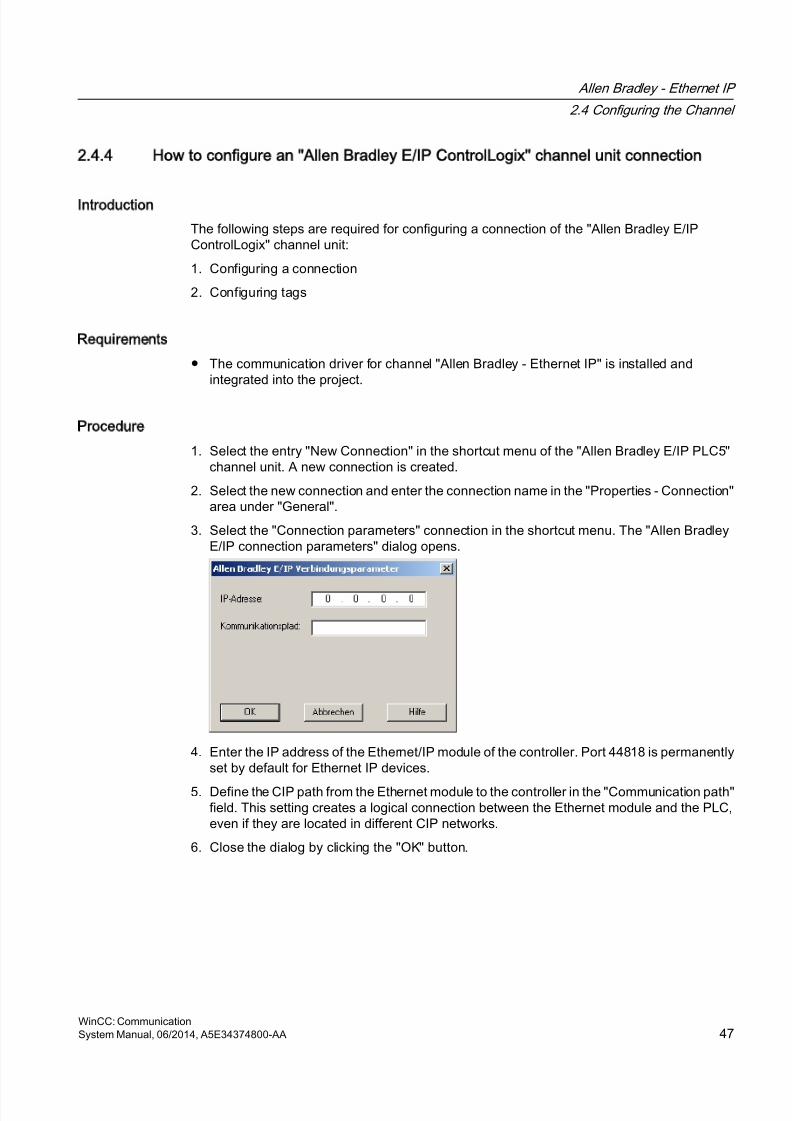
8/20/2019 WinCC Communication en-US en-US
http://slidepdf.com/reader/full/wincc-communication-en-us-en-us 47/527
2.4.4 How to configure an Allen Bradley E/IP ControlLogix channel unit connection
Introduction
The following steps are required for configuring a connection of the "Allen Bradley E/IPControlLogix" channel unit:
1. Configuring a connection
2. Configuring tags
Requirements
● The communication driver for channel "Allen Bradley - Ethernet IP" is installed andintegrated into the project.
Procedure
1. Select the entry "New Connection" in the shortcut menu of the "Allen Bradley E/IP PLC5"channel unit. A new connection is created.
2. Select the new connection and enter the connection name in the "Properties - Connection"area under "General".
3. Select the "Connection parameters" connection in the shortcut menu. The "Allen BradleyE/IP connection parameters" dialog opens.
4. Enter the IP address of the Ethernet/IP module of the controller. Port 44818 is permanentlyset by default for Ethernet IP devices.
5. Define the CIP path from the Ethernet module to the controller in the "Communication path"field. This setting creates a logical connection between the Ethernet module and the PLC,even if they are located in different CIP networks.
6. Close the dialog by clicking the "OK" button.
Allen Bradley - Ethernet IP
2.4 Configuring the Channel
WinCC: CommunicationSystem Manual, 06/2014, A5E34374800-AA 47
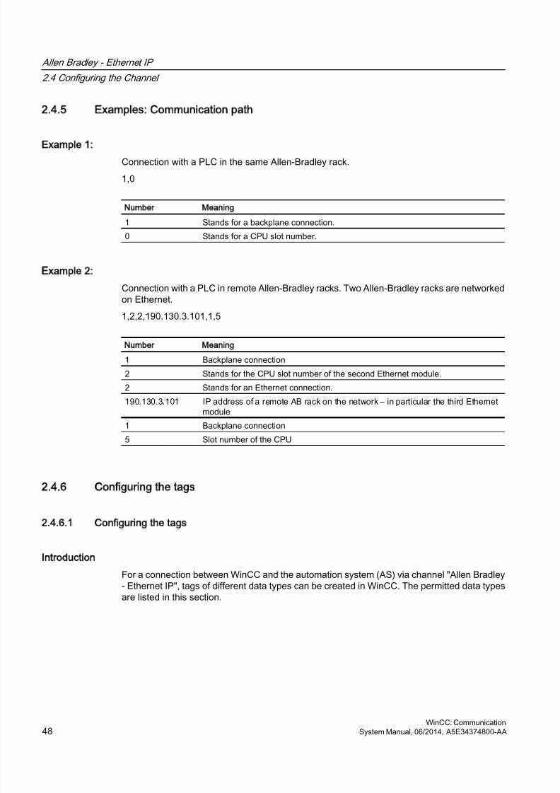
8/20/2019 WinCC Communication en-US en-US
http://slidepdf.com/reader/full/wincc-communication-en-us-en-us 48/527
2.4.5 Examples: Communication path
Example 1:
Connection with a PLC in the same Allen-Bradley rack.
1,0
Number Meaning
1 Stands for a backplane connection.
0 Stands for a CPU slot number.
Example 2:
Connection with a PLC in remote Allen-Bradley racks. Two Allen-Bradley racks are networkedon Ethernet.
1,2,2,190.130.3.101,1,5
Number Meaning
1 Backplane connection
2 Stands for the CPU slot number of the second Ethernet module.
2 Stands for an Ethernet connection.
190.130.3.101 IP address of a remote AB rack on the network – in particular the third Ethernetmodule
1 Backplane connection
5 Slot number of the CPU
2.4.6 Configuring the tags
2.4.6.1 Configuring the tags
Introduction
For a connection between WinCC and the automation system (AS) via channel "Allen Bradley- Ethernet IP", tags of different data types can be created in WinCC. The permitted data typesare listed in this section.
Allen Bradley - Ethernet IP
2.4 Configuring the Channel
WinCC: Communication48 System Manual, 06/2014, A5E34374800-AA
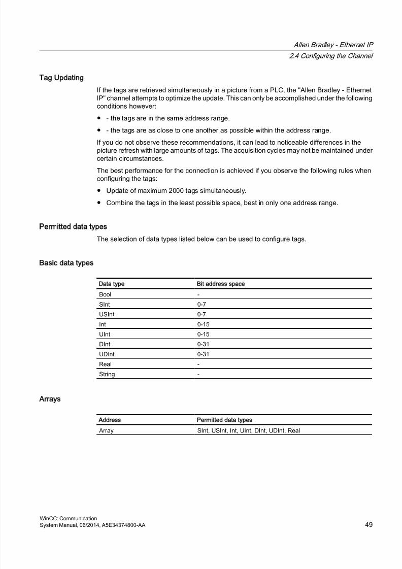
8/20/2019 WinCC Communication en-US en-US
http://slidepdf.com/reader/full/wincc-communication-en-us-en-us 49/527
Tag Updating
If the tags are retrieved simultaneously in a picture from a PLC, the "Allen Bradley - Ethernet
IP" channel attempts to optimize the update. This can only be accomplished under the followingconditions however:
● - the tags are in the same address range.
● - the tags are as close to one another as possible within the address range.
If you do not observe these recommendations, it can lead to noticeable differences in thepicture refresh with large amounts of tags. The acquisition cycles may not be maintained undercertain circumstances.
The best performance for the connection is achieved if you observe the following rules whenconfiguring the tags:
● Update of maximum 2000 tags simultaneously.
● Combine the tags in the least possible space, best in only one address range.
Permitted data types
The selection of data types listed below can be used to configure tags.
Basic data types
Data type Bit address space
Bool -
SInt 0-7
USInt 0-7
Int 0-15
UInt 0-15
DInt 0-31
UDInt 0-31
Real -
String -
Arrays
Address Permitted data types
Array SInt, USInt, Int, UInt, DInt, UDInt, Real
Allen Bradley - Ethernet IP
2.4 Configuring the Channel
WinCC: CommunicationSystem Manual, 06/2014, A5E34374800-AA 49
8/20/2019 WinCC Communication en-US en-US
http://slidepdf.com/reader/full/wincc-communication-en-us-en-us 50/527
2.4.6.2 Addressing
Addressing
A tag is uniquely referenced in WinCC by means of an address in the controller. The addressmust correspond with the tag name in the PLC. The tag address is defined by a string with alength of up to 128 characters.
Using characters for addressing
Valid characters for tag addressing:
● Letters (a to z, A to Z)
● Numbers (0 to 9)
● Underscore ( _ )
The tag address consists of tag name and other character strings used to specify the tag inthe PLC.
Tag name properties:
● The tag name may begin but not end with an underscore character.
● Strings with successive underscore and space characters are invalid.
● The address may not exceed a length of 128 characters.
Note
The characters reserved for tag addressing may not be used in program/tag names or atany other address instance.
The reserved characters are listed below:
Reserved character Function
. Element delimiter
: Definition of a program tag
, Delimiter for addressing multi-dimensional arrays
/ Reserved for bit addressing.
[ ] Addressing of array elements or arrays
Allen Bradley - Ethernet IP
2.4 Configuring the Channel
WinCC: Communication50 System Manual, 06/2014, A5E34374800-AA
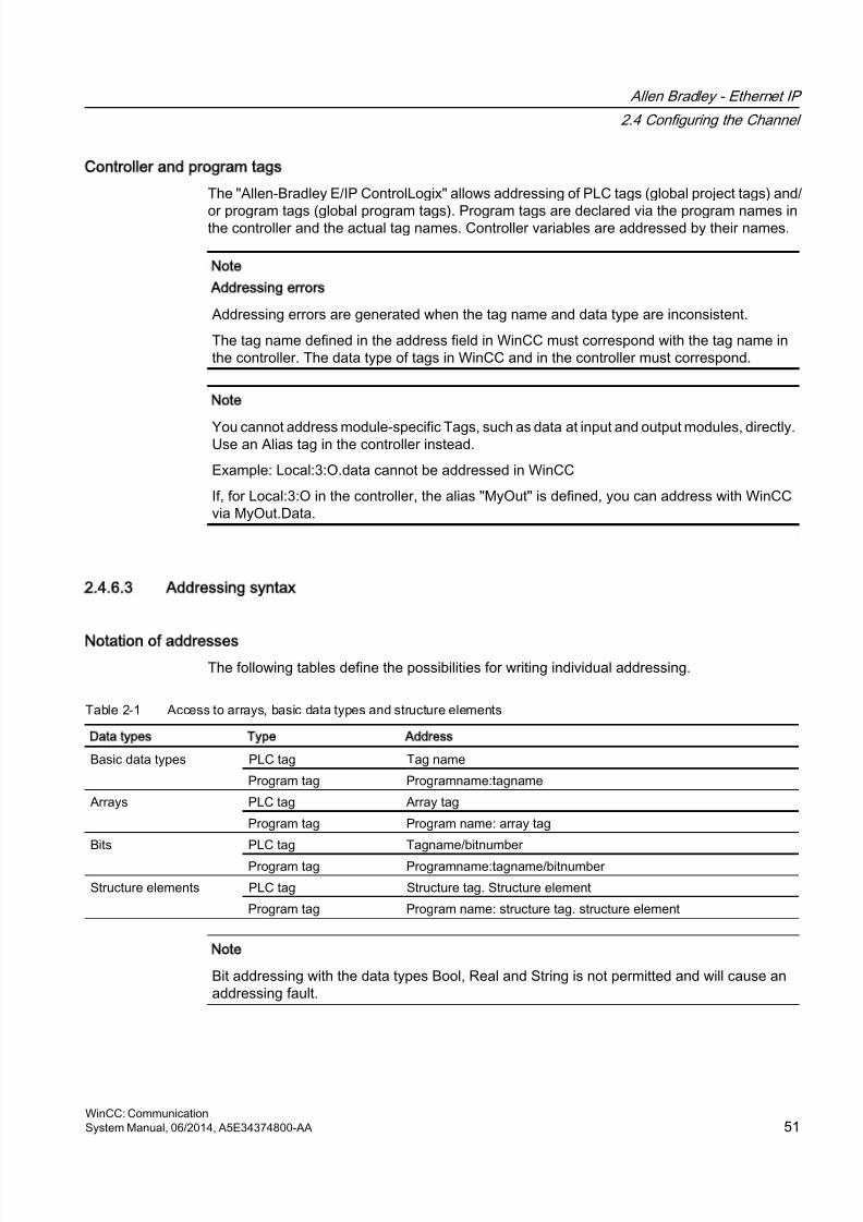
8/20/2019 WinCC Communication en-US en-US
http://slidepdf.com/reader/full/wincc-communication-en-us-en-us 51/527
Controller and program tags
The "Allen-Bradley E/IP ControlLogix" allows addressing of PLC tags (global project tags) and/
or program tags (global program tags). Program tags are declared via the program names inthe controller and the actual tag names. Controller variables are addressed by their names.
Note
Addressing errors
Addressing errors are generated when the tag name and data type are inconsistent.
The tag name defined in the address field in WinCC must correspond with the tag name inthe controller. The data type of tags in WinCC and in the controller must correspond.
Note
You cannot address module-specific Tags, such as data at input and output modules, directly.Use an Alias tag in the controller instead.
Example: Local:3:O.data cannot be addressed in WinCC
If, for Local:3:O in the controller, the alias "MyOut" is defined, you can address with WinCCvia MyOut.Data.
2.4.6.3 Addressing syntax
Notation of addresses
The following tables define the possibilities for writing individual addressing.
Table 2-1 Access to arrays, basic data types and structure elements
Data types Type Address
Basic data types PLC tag Tag name
Program tag Programname:tagname
Arrays PLC tag Array tag
Program tag Program name: array tag
Bits PLC tag Tagname/bitnumber
Program tag Programname:tagname/bitnumber
Structure elements PLC tag Structure tag. Structure element
Program tag Program name: structure tag. structure element
Note
Bit addressing with the data types Bool, Real and String is not permitted and will cause anaddressing fault.
Allen Bradley - Ethernet IP
2.4 Configuring the Channel
WinCC: CommunicationSystem Manual, 06/2014, A5E34374800-AA 51
8/20/2019 WinCC Communication en-US en-US
http://slidepdf.com/reader/full/wincc-communication-en-us-en-us 52/527
Description of the syntax
Syntax description:
(Programname:)tagname([x(,y)(,z)]){.tagname([x(,y)(,z)])}(/bitnumber)
● The "( )" defines an optional, single instance of an expression.
● The "{ }" defines an optional expression with multiple single instances.
The address string length may not exceed 128 characters.
2.4.6.4 Addressing Types
Array elements
Elements of one-dimensional, two-dimensional and three-dimensional arrays in the PLC areindexed by setting an index and the corresponding notation in the tag editor. Array addressingstarts at element "0", with arrays of all basic types being valid for element addressing. Read/write operations are only carried out at the addressed element, and not for the entire array.
Bits and bit tags
Bit access is allowed to all basic data types with the exception of Bool, Real and String. Bitaddressing is also allowed at array/structure elements. Data type Bool is defined in WinCC foraddressing bits and bit tags in the basic data types.
One-place bit numbers will be address with "/x" or "/0x" (x = bit number). Bit numbers aredefined by up to two digits.
Note
With the "Bool" data type in the data types SInt, Int and DInt, after changing the specified bitthe complete tag is then written in the PLC again. In the meantime, no check is made as towhether other bits in the tag have since changed. Therefore, the PLC may have only readaccess to the specified tag.
Structures
User-defined data types are created by means of structures. These structures group tags ofdifferent data types. Structures may consist of basic types, arrays and of other structures. InWinCC, only basic data types are addressed as structure elements and not entire structures.
Structure elements
Structure elements are addressed by means of the name of the structure and of the requiredstructure element. This addressing is separated by point. In addition to basic data types, the
Allen Bradley - Ethernet IP
2.4 Configuring the Channel
WinCC: Communication52 System Manual, 06/2014, A5E34374800-AA
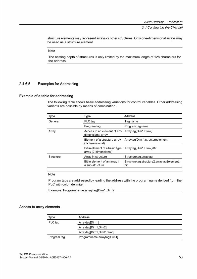
8/20/2019 WinCC Communication en-US en-US
http://slidepdf.com/reader/full/wincc-communication-en-us-en-us 53/527
structure elements may represent arrays or other structures. Only one-dimensional arrays maybe used as a structure element.
Note
The nesting depth of structures is only limited by the maximum length of 128 characters forthe address.
2.4.6.5 Examples for Addressing
Example of a table for addressing
The following table shows basic addressing variations for control variables. Other addressingvariants are possible by means of combination.
Type Type Address
General PLC tag Tag name
Program tag Program:tagname
Array Access to an element of a 2-dimensional array
Arraytag[Dim1,Dim2]
Element of a structure array(1-dimensional)
Arraytag[Dim1].structureelement
Bit in element of a basic typearray (2-dimensional)
Arraytag[Dim1,Dim2]/Bit
Structure Array in structure Structuretag.arraytag
Bit in element of an array ina sub-structure
Structuretag.structure2.arraytag [element]/bit
Note
Program tags are addressed by leading the address with the program name derived from thePLC with colon delimiter.
Example: Programname:arraytag[Dim1,Dim2]
Access to array elements
Type Address
PLC tag Arraytag[Dim1]
Arraytag[Dim1,Dim2]
Arraytag[Dim1,Dim2,Dim3]
Program tag Programname:arraytag[Dim1]
Allen Bradley - Ethernet IP
2.4 Configuring the Channel
WinCC: CommunicationSystem Manual, 06/2014, A5E34374800-AA 53
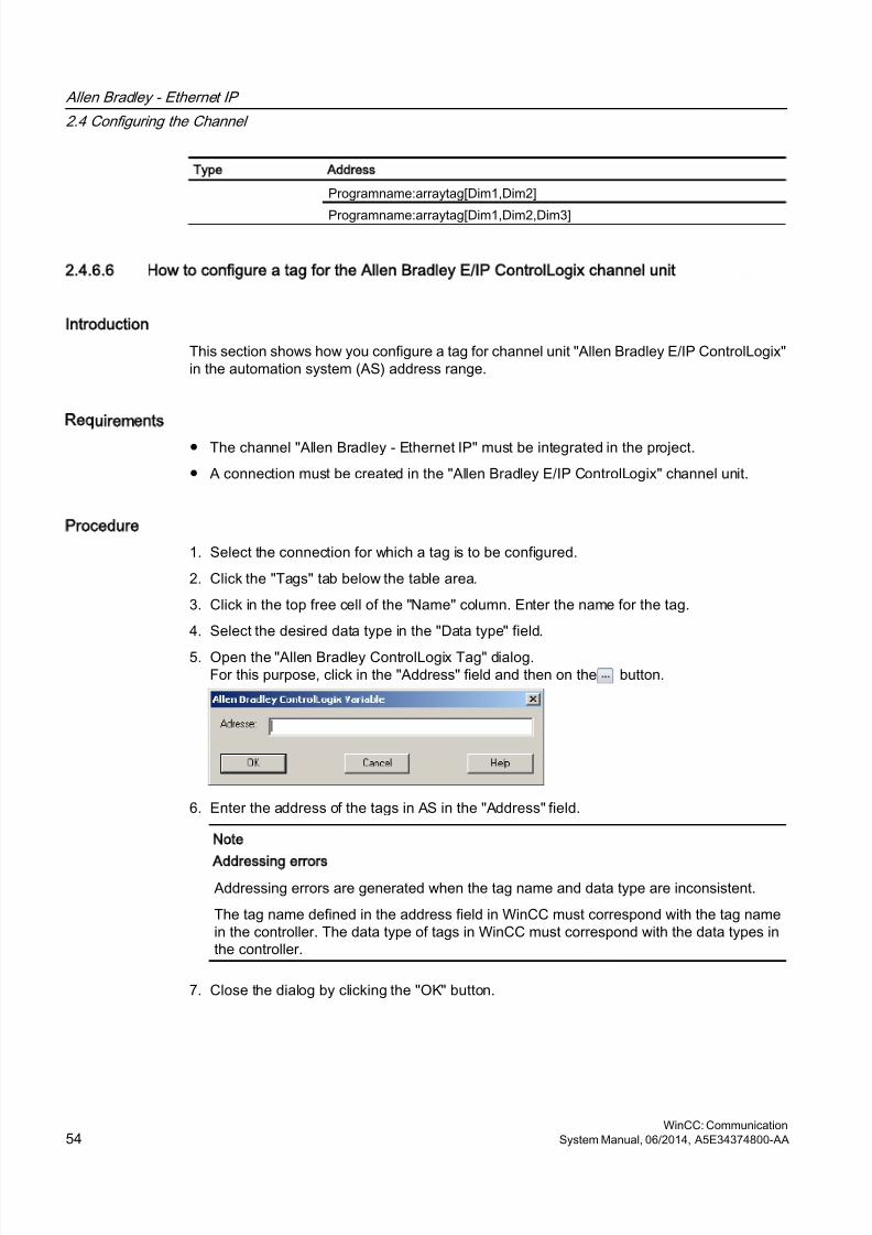
8/20/2019 WinCC Communication en-US en-US
http://slidepdf.com/reader/full/wincc-communication-en-us-en-us 54/527
Type Address
Programname:arraytag[Dim1,Dim2]
Programname:arraytag[Dim1,Dim2,Dim3]
2.4.6.6 How to configure a tag for the Allen Bradley E/IP ControlLogix channel unit
Introduction
This section shows how you configure a tag for channel unit "Allen Bradley E/IP ControlLogix"in the automation system (AS) address range.
Requirements
● The channel "Allen Bradley - Ethernet IP" must be integrated in the project.
● A connection must be created in the "Allen Bradley E/IP ControlLogix" channel unit.
Procedure
1. Select the connection for which a tag is to be configured.
2. Click the "Tags" tab below the table area.
3. Click in the top free cell of the "Name" column. Enter the name for the tag.
4. Select the desired data type in the "Data type" field.
5. Open the "Allen Bradley ControlLogix Tag" dialog.For this purpose, click in the "Address" field and then on the button.
6. Enter the address of the tags in AS in the "Address" field.
Note
Addressing errors
Addressing errors are generated when the tag name and data type are inconsistent.
The tag name defined in the address field in WinCC must correspond with the tag namein the controller. The data type of tags in WinCC must correspond with the data types inthe controller.
7. Close the dialog by clicking the "OK" button.
Allen Bradley - Ethernet IP
2.4 Configuring the Channel
WinCC: Communication54 System Manual, 06/2014, A5E34374800-AA
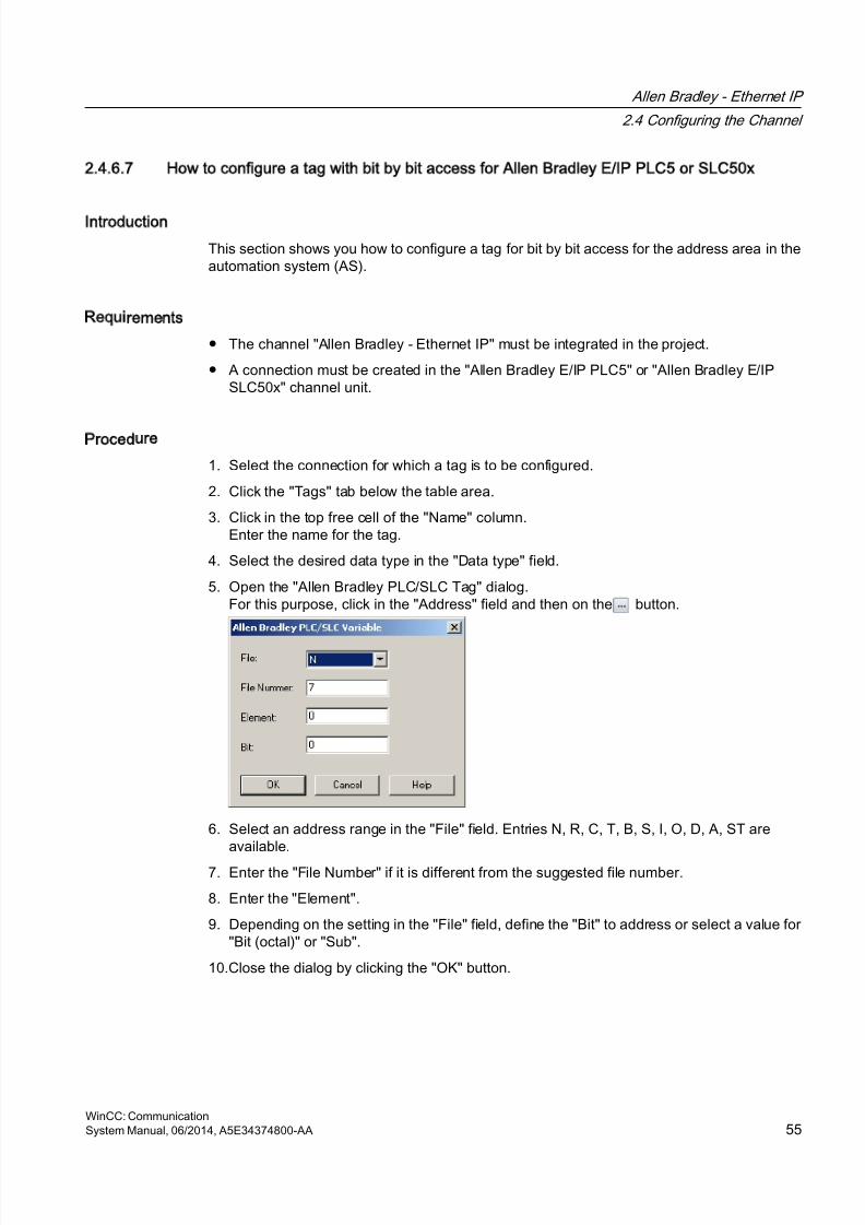
8/20/2019 WinCC Communication en-US en-US
http://slidepdf.com/reader/full/wincc-communication-en-us-en-us 55/527
2.4.6.7 How to configure a tag with bit by bit access for Allen Bradley E/IP PLC5 or SLC50x
Introduction
This section shows you how to configure a tag for bit by bit access for the address area in theautomation system (AS).
Requirements
● The channel "Allen Bradley - Ethernet IP" must be integrated in the project.
● A connection must be created in the "Allen Bradley E/IP PLC5" or "Allen Bradley E/IPSLC50x" channel unit.
Procedure
1. Select the connection for which a tag is to be configured.
2. Click the "Tags" tab below the table area.
3. Click in the top free cell of the "Name" column.Enter the name for the tag.
4. Select the desired data type in the "Data type" field.
5. Open the "Allen Bradley PLC/SLC Tag" dialog.For this purpose, click in the "Address" field and then on the button.
6. Select an address range in the "File" field. Entries N, R, C, T, B, S, I, O, D, A, ST areavailable.
7. Enter the "File Number" if it is different from the suggested file number.
8. Enter the "Element".
9. Depending on the setting in the "File" field, define the "Bit" to address or select a value for"Bit (octal)" or "Sub".
10.Close the dialog by clicking the "OK" button.
Allen Bradley - Ethernet IP
2.4 Configuring the Channel
WinCC: CommunicationSystem Manual, 06/2014, A5E34374800-AA 55
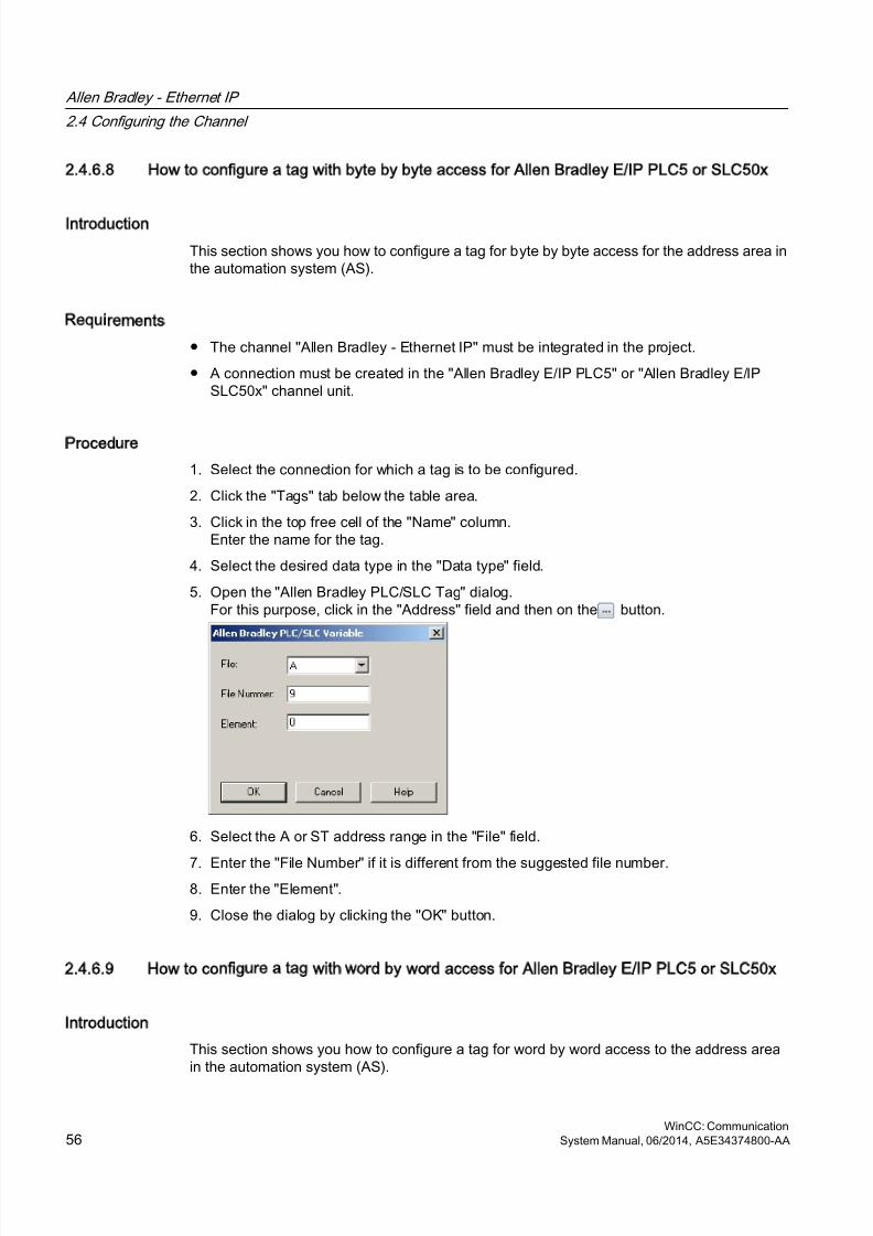
8/20/2019 WinCC Communication en-US en-US
http://slidepdf.com/reader/full/wincc-communication-en-us-en-us 56/527
2.4.6.8 How to configure a tag with byte by byte access for Allen Bradley E/IP PLC5 or SLC50x
Introduction
This section shows you how to configure a tag for byte by byte access for the address area inthe automation system (AS).
Requirements
● The channel "Allen Bradley - Ethernet IP" must be integrated in the project.
● A connection must be created in the "Allen Bradley E/IP PLC5" or "Allen Bradley E/IPSLC50x" channel unit.
Procedure
1. Select the connection for which a tag is to be configured.
2. Click the "Tags" tab below the table area.
3. Click in the top free cell of the "Name" column.Enter the name for the tag.
4. Select the desired data type in the "Data type" field.
5. Open the "Allen Bradley PLC/SLC Tag" dialog.For this purpose, click in the "Address" field and then on the button.
6. Select the A or ST address range in the "File" field.
7. Enter the "File Number" if it is different from the suggested file number.8. Enter the "Element".
9. Close the dialog by clicking the "OK" button.
2.4.6.9 How to configure a tag with word by word access for Allen Bradley E/IP PLC5 or SLC50x
Introduction
This section shows you how to configure a tag for word by word access to the address areain the automation system (AS).
Allen Bradley - Ethernet IP
2.4 Configuring the Channel
WinCC: Communication56 System Manual, 06/2014, A5E34374800-AA
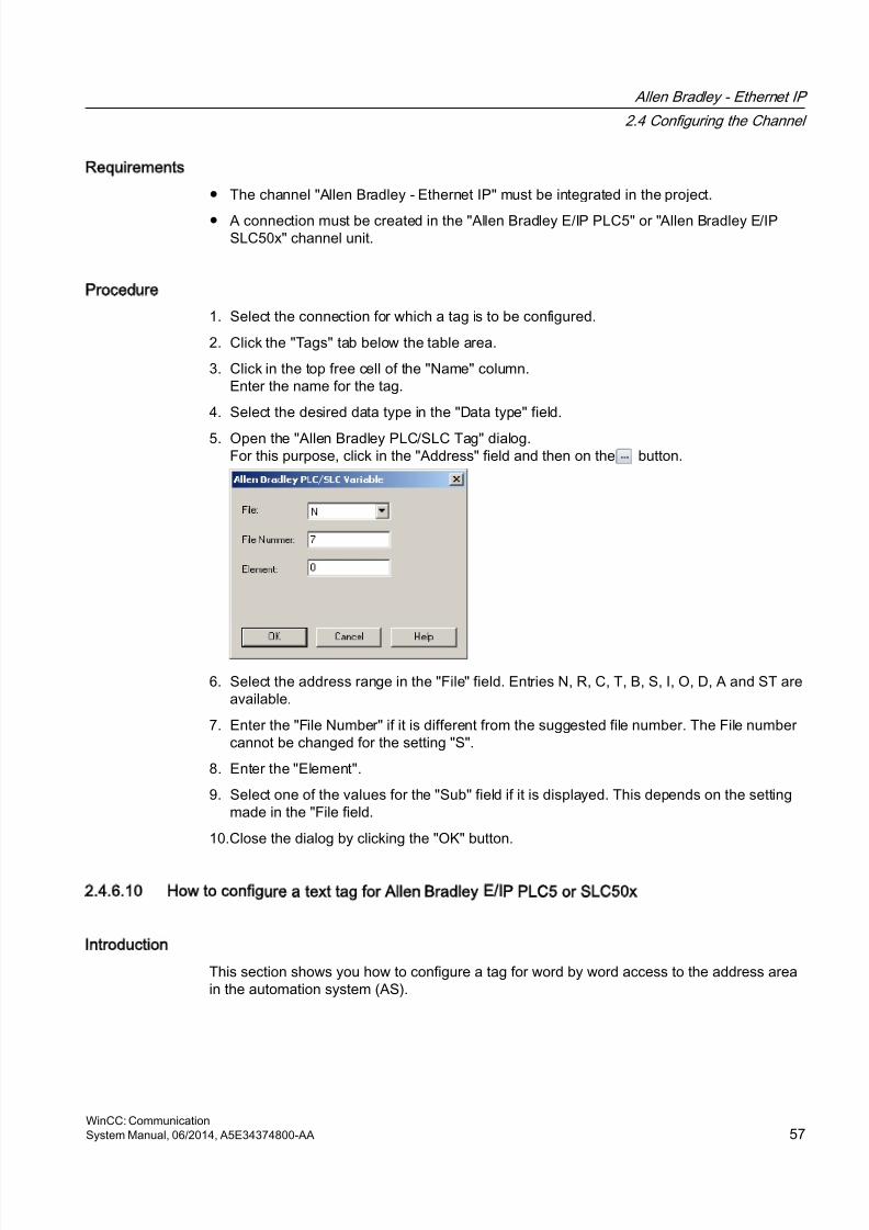
8/20/2019 WinCC Communication en-US en-US
http://slidepdf.com/reader/full/wincc-communication-en-us-en-us 57/527
Requirements
● The channel "Allen Bradley - Ethernet IP" must be integrated in the project.
● A connection must be created in the "Allen Bradley E/IP PLC5" or "Allen Bradley E/IPSLC50x" channel unit.
Procedure
1. Select the connection for which a tag is to be configured.
2. Click the "Tags" tab below the table area.
3. Click in the top free cell of the "Name" column.Enter the name for the tag.
4. Select the desired data type in the "Data type" field.
5. Open the "Allen Bradley PLC/SLC Tag" dialog.For this purpose, click in the "Address" field and then on the button.
6. Select the address range in the "File" field. Entries N, R, C, T, B, S, I, O, D, A and ST areavailable.
7. Enter the "File Number" if it is different from the suggested file number. The File numbercannot be changed for the setting "S".
8. Enter the "Element".
9. Select one of the values for the "Sub" field if it is displayed. This depends on the settingmade in the "File field.
10.Close the dialog by clicking the "OK" button.
2.4.6.10 How to configure a text tag for Allen Bradley E/IP PLC5 or SLC50x
Introduction
This section shows you how to configure a tag for word by word access to the address areain the automation system (AS).
Allen Bradley - Ethernet IP
2.4 Configuring the Channel
WinCC: CommunicationSystem Manual, 06/2014, A5E34374800-AA 57
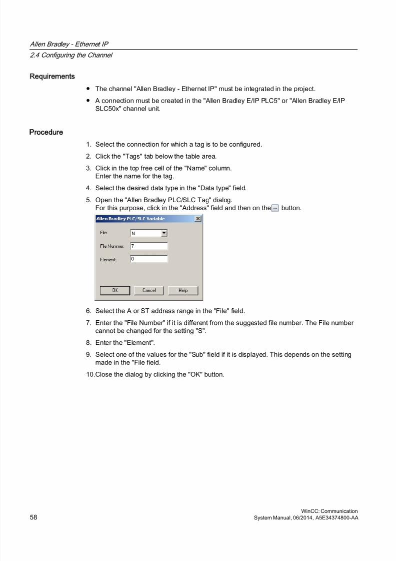
8/20/2019 WinCC Communication en-US en-US
http://slidepdf.com/reader/full/wincc-communication-en-us-en-us 58/527
Requirements
● The channel "Allen Bradley - Ethernet IP" must be integrated in the project.
● A connection must be created in the "Allen Bradley E/IP PLC5" or "Allen Bradley E/IPSLC50x" channel unit.
Procedure
1. Select the connection for which a tag is to be configured.
2. Click the "Tags" tab below the table area.
3. Click in the top free cell of the "Name" column.Enter the name for the tag.
4. Select the desired data type in the "Data type" field.
5. Open the "Allen Bradley PLC/SLC Tag" dialog.For this purpose, click in the "Address" field and then on the button.
6. Select the A or ST address range in the "File" field.
7. Enter the "File Number" if it is different from the suggested file number. The File numbercannot be changed for the setting "S".
8. Enter the "Element".
9. Select one of the values for the "Sub" field if it is displayed. This depends on the settingmade in the "File field.
10.Close the dialog by clicking the "OK" button.
Allen Bradley - Ethernet IP
2.4 Configuring the Channel
WinCC: Communication58 System Manual, 06/2014, A5E34374800-AA
8/20/2019 WinCC Communication en-US en-US
http://slidepdf.com/reader/full/wincc-communication-en-us-en-us 59/527
Mitsubishi Ethernet
3
3.1 WinCC channel Mitsubishi Ethernet
Introduction
The "Mitsubishi Ethernet" channel is intended for communication between a WinCC stationand Mitsubishi controllers of the FX3U and Q series. The communication takes place via theMELSEC communication protocol (MC protocol).
Channel units
The "Mitsubishi Ethernet" channel comes equipped with the "Mitsubishi FX3U Series" and"Mitsubishi Q Series" channel units.
WinCC: CommunicationSystem Manual, 06/2014, A5E34374800-AA 59
8/20/2019 WinCC Communication en-US en-US
http://slidepdf.com/reader/full/wincc-communication-en-us-en-us 60/527
3.2 Supported data types
Introduction
Define the required tags for a logical connection between WinCC and a connected controller.
The following data types are supported by the "Mitsubishi Ethernet" channel:
● Binary Tag
● Signed 16-bit value
● Unsigned 16-bit value
● Signed 32-bit value
● Unsigned 32-bit value
● Floating-point number 32-bit IEEE 754● Floating-point number 64-bit IEEE 754
● Text tag 8-bit character set
● Text tag 16-bit character set
● Raw Data Tag
Mitsubishi Ethernet
3.2 Supported data types
WinCC: Communication60 System Manual, 06/2014, A5E34374800-AA
8/20/2019 WinCC Communication en-US en-US
http://slidepdf.com/reader/full/wincc-communication-en-us-en-us 61/527
3.3 Configuring the Channel
3.3.1 Configuring the Mitsubishi Ethernet channel
Introduction
WinCC needs a logical connection for communication of WinCC with the automation system(AS). This section illustrates how to configure the "Mitsubishi Ethernet" channel.
You can establish a connection to an AS with either TCP/IP or UDP/IP protocol. Therefore,you have to enter the IP address and IP port number for the AS when configuring a logicalconnection for the channel "Mitsubishi Ethernet" and select either the UDP or TCP/IP protocol.The IP address consists of four numerical values, separated by dots. The numerical valuesmust be within the range 0 to 255.
Note
Timeout Behavior
Interrupted connections are not detected immediately when using the TCP/IP protocol. Thefeedback can take longer and is dependent on the operating system.
Mitsubishi controllers that are supported
You can configure logical connections for the following Mitsubishi controllers:● MELSEC FX3U series
● MELSEC System Q
When you configure the connections and tags, the procedure is identical for both controllerfamilies. The configuration differs only in relation to the used address type of the specificcontroller family. In addition, the routing of information is only supported by MELSEC SystemQ models.
Online Configuration
The "Mitsubishi Ethernet channel supports the online configuration of tags and connections.
3.3.2 How to configure a Mitsubishi FX3U Series channel unit connection
Introduction
The following steps are required for configuring the "Mitsubishi Ethernet" channel:
1. Configuring a connection
2. Configuring tags
Mitsubishi Ethernet
3.3 Configuring the Channel
WinCC: CommunicationSystem Manual, 06/2014, A5E34374800-AA 61
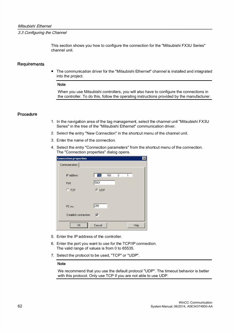
8/20/2019 WinCC Communication en-US en-US
http://slidepdf.com/reader/full/wincc-communication-en-us-en-us 62/527
This section shows you how to configure the connection for the "Mitsubishi FX3U Series"channel unit.
Requirements
● The communication driver for the "Mitsubishi Ethernet" channel is installed and integratedinto the project.
Note
When you use Mitsubishi controllers, you will also have to configure the connections inthe controller. To do this, follow the operating instructions provided by the manufacturer.
Procedure
1. In the navigation area of the tag management, select the channel unit "Mitsubishi FX3USeries" in the tree of the "Mitsubishi Ethernet" communication driver.
2. Select the entry "New Connection" in the shortcut menu of the channel unit.
3. Enter the name of the connection.
4. Select the entry "Connection parameters" from the shortcut menu of the connection.The "Connection properties" dialog opens.
5. Enter the IP address of the controller.
6. Enter the port you want to use for the TCP/IP connection.The valid range of values is from 0 to 65535.
7. Select the protocol to be used, "TCP" or "UDP".
Note
We recommend that you use the default protocol "UDP". The timeout behavior is betterwith this protocol. Only use TCP if you are not able to use UDP.
Mitsubishi Ethernet
3.3 Configuring the Channel
WinCC: Communication62 System Manual, 06/2014, A5E34374800-AA
8/20/2019 WinCC Communication en-US en-US
http://slidepdf.com/reader/full/wincc-communication-en-us-en-us 63/527
8. Enter the PC number.If you do not want to enter a PC number, you must enter the value 255 or 0.
9. To establish the connection, select "Establish connection".10.In each case, close the dialog with "OK".
3.3.3 How to configure a Mitsubishi Q Series channel unit connection
Introduction
The following steps are required for configuring the "Mitsubishi Ethernet" channel:
1. Configuring a connection.
2. Configuring tags.
This section shows you how to configure the connection for the "Mitsubishi Q Series" channelunit.
Requirements
● The communication driver for the "Mitsubishi Ethernet" channel is installed and integratedinto the project.
Note
When you use Mitsubishi controllers, you will also have to configure the connections inthe controller. To do this, follow the operating instructions provided by the manufacturer.
Procedure
1. In the navigation area of the tag management, select the channel unit "Mitsubishi Q Series"in the tree of the communication driver "Mitsubishi Ethernet".
2. Select the entry "New Connection" in the shortcut menu of the channel unit.
3. Enter the name of the connection.
Mitsubishi Ethernet
3.3 Configuring the Channel
WinCC: CommunicationSystem Manual, 06/2014, A5E34374800-AA 63
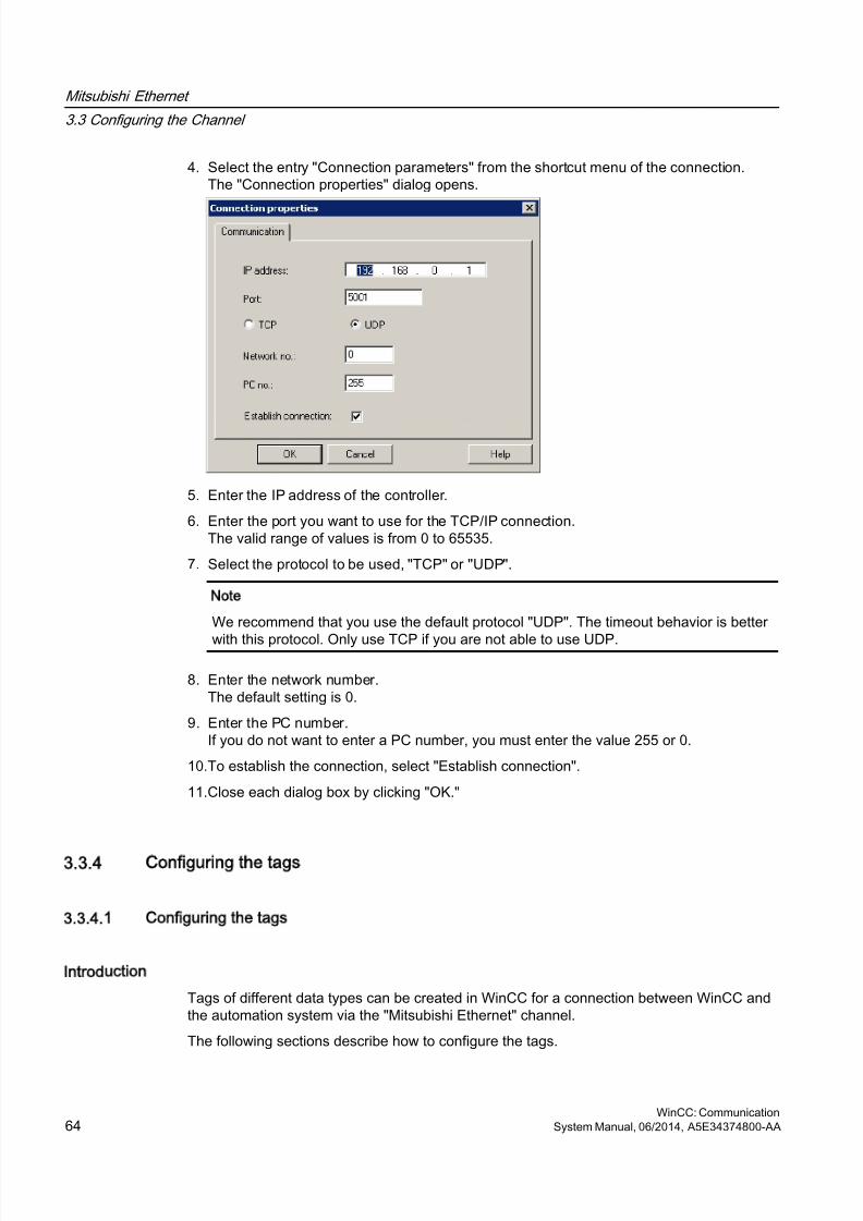
8/20/2019 WinCC Communication en-US en-US
http://slidepdf.com/reader/full/wincc-communication-en-us-en-us 64/527
4. Select the entry "Connection parameters" from the shortcut menu of the connection.The "Connection properties" dialog opens.
5. Enter the IP address of the controller.
6. Enter the port you want to use for the TCP/IP connection.The valid range of values is from 0 to 65535.
7. Select the protocol to be used, "TCP" or "UDP".
Note
We recommend that you use the default protocol "UDP". The timeout behavior is better
with this protocol. Only use TCP if you are not able to use UDP.
8. Enter the network number.The default setting is 0.
9. Enter the PC number.If you do not want to enter a PC number, you must enter the value 255 or 0.
10.To establish the connection, select "Establish connection".
11.Close each dialog box by clicking "OK."
3.3.4 Configuring the tags
3.3.4.1 Configuring the tags
Introduction
Tags of different data types can be created in WinCC for a connection between WinCC andthe automation system via the "Mitsubishi Ethernet" channel.
The following sections describe how to configure the tags.
Mitsubishi Ethernet
3.3 Configuring the Channel
WinCC: Communication64 System Manual, 06/2014, A5E34374800-AA
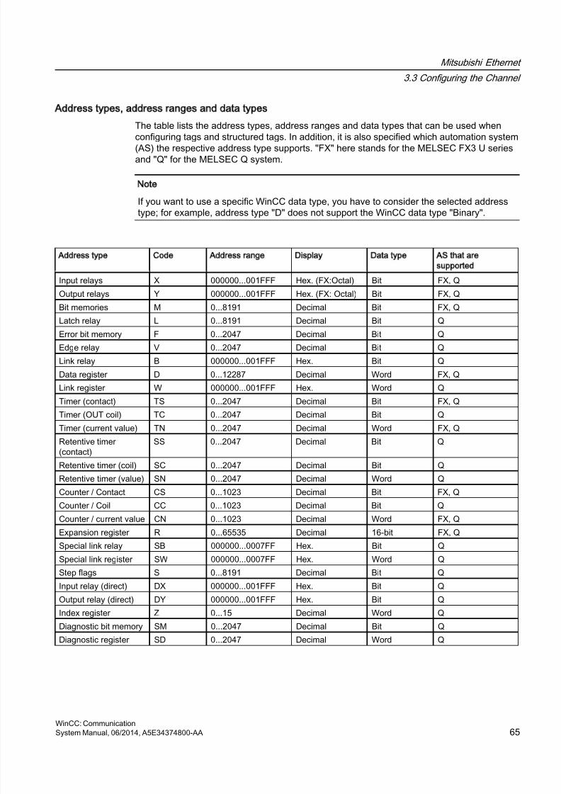
8/20/2019 WinCC Communication en-US en-US
http://slidepdf.com/reader/full/wincc-communication-en-us-en-us 65/527
Address types, address ranges and data types
The table lists the address types, address ranges and data types that can be used when
configuring tags and structured tags. In addition, it is also specified which automation system(AS) the respective address type supports. "FX" here stands for the MELSEC FX3 U seriesand "Q" for the MELSEC Q system.
Note
If you want to use a specific WinCC data type, you have to consider the selected addresstype; for example, address type "D" does not support the WinCC data type "Binary".
Address type Code Address range Display Data type AS that are
supported
Input relays X 000000...001FFF Hex. (FX:Octal) Bit FX, QOutput relays Y 000000...001FFF Hex. (FX: Octal) Bit FX, Q
Bit memories M 0...8191 Decimal Bit FX, Q
Latch relay L 0...8191 Decimal Bit Q
Error bit memory F 0...2047 Decimal Bit Q
Edge relay V 0...2047 Decimal Bit Q
Link relay B 000000...001FFF Hex. Bit Q
Data register D 0...12287 Decimal Word FX, Q
Link register W 000000...001FFF Hex. Word Q
Timer (contact) TS 0...2047 Decimal Bit FX, Q
Timer (OUT coil) TC 0...2047 Decimal Bit QTimer (current value) TN 0...2047 Decimal Word FX, Q
Retentive timer(contact)
SS 0...2047 Decimal Bit Q
Retentive timer (coil) SC 0...2047 Decimal Bit Q
Retentive timer (value) SN 0...2047 Decimal Word Q
Counter / Contact CS 0...1023 Decimal Bit FX, Q
Counter / Coil CC 0...1023 Decimal Bit Q
Counter / current value CN 0...1023 Decimal Word FX, Q
Expansion register R 0...65535 Decimal 16-bit FX, Q
Special link relay SB 000000...0007FF Hex. Bit Q
Special link register SW 000000...0007FF Hex. Word QStep flags S 0...8191 Decimal Bit Q
Input relay (direct) DX 000000...001FFF Hex. Bit Q
Output relay (direct) DY 000000...001FFF Hex. Bit Q
Index register Z 0...15 Decimal Word Q
Diagnostic bit memory SM 0...2047 Decimal Bit Q
Diagnostic register SD 0...2047 Decimal Word Q
Mitsubishi Ethernet
3.3 Configuring the Channel
WinCC: CommunicationSystem Manual, 06/2014, A5E34374800-AA 65
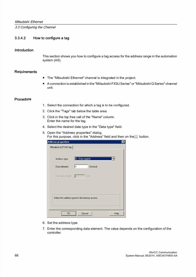
8/20/2019 WinCC Communication en-US en-US
http://slidepdf.com/reader/full/wincc-communication-en-us-en-us 66/527
3.3.4.2 How to configure a tag
Introduction
This section shows you how to configure a tag access for the address range in the automationsystem (AS).
Requirements
● The "Mitsubishi Ethernet" channel is integrated in the project.
● A connection is established in the "Mitsubishi FX3U Series" or "Mitsubishi Q Series" channelunit.
Procedure
1. Select the connection for which a tag is to be configured.
2. Click the "Tags" tab below the table area.
3. Click in the top free cell of the "Name" column.Enter the name for the tag.
4. Select the desired data type in the "Data type" field.
5. Open the "Address properties" dialog.For this purpose, click in the "Address" field and then on the button.
6. Set the address type.
7. Enter the corresponding data element. The value depends on the configuration of thecontroller.
Mitsubishi Ethernet
3.3 Configuring the Channel
WinCC: Communication66 System Manual, 06/2014, A5E34374800-AA

8/20/2019 WinCC Communication en-US en-US
http://slidepdf.com/reader/full/wincc-communication-en-us-en-us 67/527
8. If necessary, enter the raw data length.
9. Close the "Address properties" dialog by clicking "OK".
The address of the tag is displayed in the "Address" field of the "Tag properties" dialog.The address is adjusted to the data format of the AS.
Mitsubishi Ethernet
3.3 Configuring the Channel
WinCC: CommunicationSystem Manual, 06/2014, A5E34374800-AA 67

8/20/2019 WinCC Communication en-US en-US
http://slidepdf.com/reader/full/wincc-communication-en-us-en-us 68/527
8/20/2019 WinCC Communication en-US en-US
http://slidepdf.com/reader/full/wincc-communication-en-us-en-us 69/527
Modbus TCPIP
4
4.1 Modbus TCP/IP channel
Introduction
The "Modbus TCPIP" channel is for communication between a WinCC station and PLCs thatsupport Modbus via Ethernet. The communication is handled with the Modbus TCP/IP protocol.
Channel units
The "Modbus TCPIP" channel comes with the "Modbus TCP/IP Unit #1" channel unit.
WinCC: CommunicationSystem Manual, 06/2014, A5E34374800-AA 69
8/20/2019 WinCC Communication en-US en-US
http://slidepdf.com/reader/full/wincc-communication-en-us-en-us 70/527
4.2 Supported Data Types
Introduction
Define the required tags for a logical connection with a connected controller. The followingdata types are supported by the "Modbus TCPIP" channel:
● Binary tag
● Signed 16-bit value
● Unsigned 16-bit value
● Signed 32-bit value
● Unsigned 32-bit value
● Floating-point number 32-bit IEEE 754● Text tag 8-bit character set
● Text tag 16-bit character set
Modbus TCPIP
4.2 Supported Data Types
WinCC: Communication70 System Manual, 06/2014, A5E34374800-AA
8/20/2019 WinCC Communication en-US en-US
http://slidepdf.com/reader/full/wincc-communication-en-us-en-us 71/527
4.3 Configuring the Channel
4.3.1 Configuring the Modbus TCPIP Channel
Introduction
WinCC needs a logical connection for communication of WinCC with the automation system(AS). This section describes the communication with the "Modbus TCP/IP Unit #1" channelunit. All connection-specific parameters are defined during the setup.
When implementing the TCP/IP protocol, you must define the IP address of the AS for thelogic connection. The IP address consists of four numerical values, separated by dots. Thenumerical values must be within the range of 0-255.
Note
Timeout Behavior
Interrupted connections are not detected immediately when using the TCP/IP protocol. Thecheck-back message can take up to a minute.
Enabled Communication Methods with Modbus TCPIP
The following types of communication have been system-tested and approved:
● Point-to-point communication
● Multiple point connection of the WinCC station with an optional amount of controllers.
Note
Integrating the WinCC station via a bridge in a Modbus network is not possible becausethe WinCC station works as a Modbus Master.
Online Configuration
The Online configuration is not supported.
4.3.2 How to configure a connection
Introduction
The following steps are required for configuring the channel "Modbus TCPIP":
1. Configuring a connection
2. Configuring tags
Modbus TCPIP
4.3 Configuring the Channel
WinCC: CommunicationSystem Manual, 06/2014, A5E34374800-AA 71
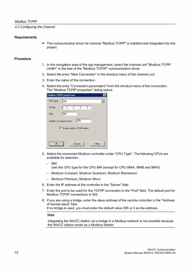
8/20/2019 WinCC Communication en-US en-US
http://slidepdf.com/reader/full/wincc-communication-en-us-en-us 72/527
Requirements
● The communication driver for channel "Modbus TCPIP" is installed and integrated into the
project.
Procedure
1. In the navigation area of the tag management, select the channel unit "Modbus TCPIPUnit#1" in the tree of the "Modbus TCP/IP" communication driver.
2. Select the entry "New Connection" in the shortcut menu of the channel unit.
3. Enter the name of the connection.
4. Select the entry "Connection parameters" from the shortcut menu of the connection.The "Modbus TCPIP properties" dialog opens.
5. Select the connected Modicon controller under "CPU Type". The following CPUs areavailable for selection:
– 984Use this CPU type for the CPU 984 (except for CPU 984A, 984B and 984X).
– Modicon Compact, Modicon Quantum, Modicon Momentum
– Modicon Premium, Modicon Micro
6. Enter the IP address of the controller in the "Server" field.
7. Enter the port to be used for the TCP/IP connection in the "Port" field. The default port forModbus TCP/IP connections is 502.
8. If you are using a bridge, enter the slave address of the remote controller in the "Addressof remote slave" field.If no bridge is used, you must enter the default value 255 or 0 as the address.
Note
Integrating the WinCC station via a bridge in a Modbus network is not possible becausethe WinCC station works as a Modbus Master.
Modbus TCPIP
4.3 Configuring the Channel
WinCC: Communication72 System Manual, 06/2014, A5E34374800-AA

8/20/2019 WinCC Communication en-US en-US
http://slidepdf.com/reader/full/wincc-communication-en-us-en-us 73/527
9. To swap the order of the 16-bit register in 32-bit process values, select "Swap words in 32-bit values".
10.Close the dialog by clicking "OK".
4.3.3 Configuring the tags
4.3.3.1 Configuring the tags
Introduction
For a connection between WinCC and the automation system (AS) via channel "ModbusTCPIP", tags of different data types can be created in WinCC.
The following sections describe how to configure the tags. The addressing of the data rangein the AS and the data type of the WinCC tags are different.
Tag Updating with the Modbus TCP/IP protocol
If the tags are retrieved simultaneously in a picture from a controller, the Modbus TCP/IPchannel attempts to optimize the update. This can only be accomplished under the followingconditions however:
● The tags are in the same address range.
● The tags are as close to one another as possible within the address range.If you do not observe these recommendations, it can lead to noticeable differences in thepicture refresh with large amounts of tags. The acquisition cycles may not be maintained undercertain circumstances.
The best performance for the connection is achieved if you observe the following rules whenconfiguring the tags:
● Update of maximum 2000 tags simultaneously.
● Combine the tags in the least possible space, best in only one address range.
Data Types and Address Ranges in the Controller
The table lists the data types and address ranges that can be used when configuring tags andstructured tags.
Name
Area with CPU
Premium/Micro
Area with CPU 984,
Compact, Quantum,
Momentum
data type
Coil(discrete output)
%M 1) 0x Bit
Discrete input (%I) – not realized byPremium/Micro
1x Bit
Modbus TCPIP
4.3 Configuring the Channel
WinCC: CommunicationSystem Manual, 06/2014, A5E34374800-AA 73
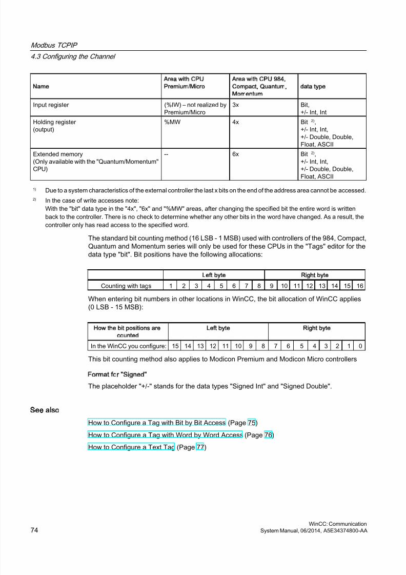
8/20/2019 WinCC Communication en-US en-US
http://slidepdf.com/reader/full/wincc-communication-en-us-en-us 74/527
Name
Area with CPU
Premium/Micro
Area with CPU 984,
Compact, Quantum,
Momentum
data type
Input register (%IW) – not realized byPremium/Micro
3x Bit,+/- Int, Int
Holding register (output)
%MW 4x Bit 2),+/- Int, Int,+/- Double, Double,Float, ASCII
Extended memory(Only available with the "Quantum/Momentum"CPU)
-- 6x Bit 2),+/- Int, Int,+/- Double, Double,Float, ASCII
1) Due to a system characteristics of the external controller the last x bits on the end of the address area cannot be accessed.2)
In the case of write accesses note:With the "bit" data type in the "4x", "6x" and "%MW" areas, after changing the specified bit the entire word is writtenback to the controller. There is no check to determine whether any other bits in the word have changed. As a result, thecontroller only has read access to the specified word.
The standard bit counting method (16 LSB - 1 MSB) used with controllers of the 984, Compact,Quantum and Momentum series will only be used for these CPUs in the "Tags" editor for thedata type "bit". Bit positions have the following allocations:
Left byte Right byte
Counting with tags 1 2 3 4 5 6 7 8 9 10 11 12 13 14 15 16
When entering bit numbers in other locations in WinCC, the bit allocation of WinCC applies(0 LSB - 15 MSB):
How the bit positions are
counted
Left byte Right byte
In the WinCC you configure: 15 14 13 12 11 10 9 8 7 6 5 4 3 2 1 0
This bit counting method also applies to Modicon Premium and Modicon Micro controllers
Format for Signed
The placeholder "+/-" stands for the data types "Signed Int" and "Signed Double".
See also
How to Configure a Tag with Bit by Bit Access (Page 75)
How to Configure a Tag with Word by Word Access (Page 76)
How to Configure a Text Tag (Page 77)
Modbus TCPIP
4.3 Configuring the Channel
WinCC: Communication74 System Manual, 06/2014, A5E34374800-AA
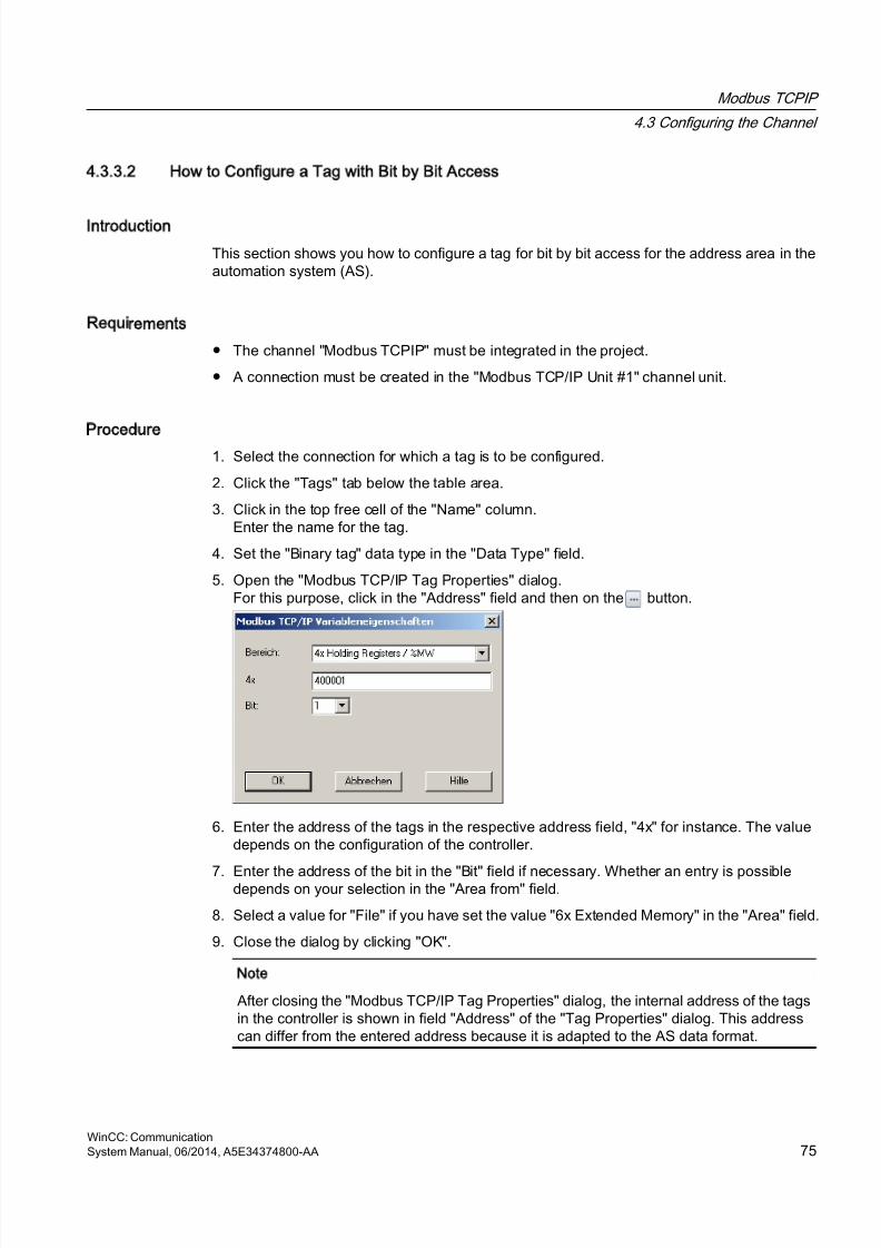
8/20/2019 WinCC Communication en-US en-US
http://slidepdf.com/reader/full/wincc-communication-en-us-en-us 75/527
4.3.3.2 How to Configure a Tag with Bit by Bit Access
Introduction
This section shows you how to configure a tag for bit by bit access for the address area in theautomation system (AS).
Requirements
● The channel "Modbus TCPIP" must be integrated in the project.
● A connection must be created in the "Modbus TCP/IP Unit #1" channel unit.
Procedure
1. Select the connection for which a tag is to be configured.
2. Click the "Tags" tab below the table area.
3. Click in the top free cell of the "Name" column.Enter the name for the tag.
4. Set the "Binary tag" data type in the "Data Type" field.
5. Open the "Modbus TCP/IP Tag Properties" dialog.For this purpose, click in the "Address" field and then on the button.
6. Enter the address of the tags in the respective address field, "4x" for instance. The valuedepends on the configuration of the controller.
7. Enter the address of the bit in the "Bit" field if necessary. Whether an entry is possibledepends on your selection in the "Area from" field.
8. Select a value for "File" if you have set the value "6x Extended Memory" in the "Area" field.
9. Close the dialog by clicking "OK".
Note
After closing the "Modbus TCP/IP Tag Properties" dialog, the internal address of the tagsin the controller is shown in field "Address" of the "Tag Properties" dialog. This addresscan differ from the entered address because it is adapted to the AS data format.
Modbus TCPIP
4.3 Configuring the Channel
WinCC: CommunicationSystem Manual, 06/2014, A5E34374800-AA 75
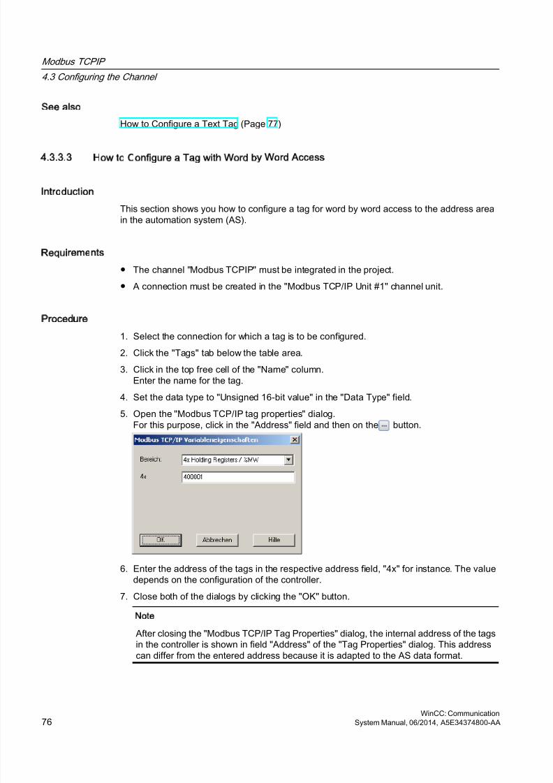
8/20/2019 WinCC Communication en-US en-US
http://slidepdf.com/reader/full/wincc-communication-en-us-en-us 76/527
See also
How to Configure a Text Tag (Page 77)
4.3.3.3 How to Configure a Tag with Word by Word Access
Introduction
This section shows you how to configure a tag for word by word access to the address areain the automation system (AS).
Requirements
● The channel "Modbus TCPIP" must be integrated in the project.● A connection must be created in the "Modbus TCP/IP Unit #1" channel unit.
Procedure
1. Select the connection for which a tag is to be configured.
2. Click the "Tags" tab below the table area.
3. Click in the top free cell of the "Name" column.Enter the name for the tag.
4. Set the data type to "Unsigned 16-bit value" in the "Data Type" field.
5. Open the "Modbus TCP/IP tag properties" dialog.For this purpose, click in the "Address" field and then on the button.
6. Enter the address of the tags in the respective address field, "4x" for instance. The valuedepends on the configuration of the controller.
7. Close both of the dialogs by clicking the "OK" button.
Note
After closing the "Modbus TCP/IP Tag Properties" dialog, the internal address of the tagsin the controller is shown in field "Address" of the "Tag Properties" dialog. This addresscan differ from the entered address because it is adapted to the AS data format.
Modbus TCPIP
4.3 Configuring the Channel
WinCC: Communication76 System Manual, 06/2014, A5E34374800-AA
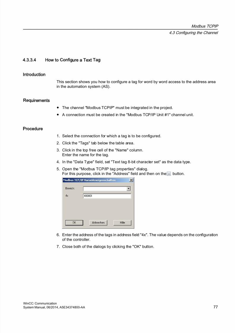
8/20/2019 WinCC Communication en-US en-US
http://slidepdf.com/reader/full/wincc-communication-en-us-en-us 77/527
4.3.3.4 How to Configure a Text Tag
Introduction
This section shows you how to configure a tag for word by word access to the address areain the automation system (AS).
Requirements
● The channel "Modbus TCPIP" must be integrated in the project.
● A connection must be created in the "Modbus TCP/IP Unit #1" channel unit.
Procedure
1. Select the connection for which a tag is to be configured.
2. Click the "Tags" tab below the table area.
3. Click in the top free cell of the "Name" column.Enter the name for the tag.
4. In the "Data Type" field, set "Text tag 8-bit character set" as the data type.
5. Open the "Modbus TCP/IP tag properties" dialog.
For this purpose, click in the "Address" field and then on the button.
6. Enter the address of the tags in address field "4x". The value depends on the configurationof the controller.
7. Close both of the dialogs by clicking the "OK" button.
Modbus TCPIP
4.3 Configuring the Channel
WinCC: CommunicationSystem Manual, 06/2014, A5E34374800-AA 77

8/20/2019 WinCC Communication en-US en-US
http://slidepdf.com/reader/full/wincc-communication-en-us-en-us 78/527
8/20/2019 WinCC Communication en-US en-US
http://slidepdf.com/reader/full/wincc-communication-en-us-en-us 79/527
OPC Channel
5
5.1 WinCC OPC Channel
Introduction
WinCC can be used as both an OPC server and as an OPC client. The OPC channel is theOPC client application of WinCC.
The OPC communication driver can be used as OPC DA client, OPC XML client, and OPCUA client.
The following OPC components are installed automatically:
● OPC communication driver
● OPC Item Manager
Possible Applications
WinCC as an OPC DA client
If WinCC is used as an OPC DA client, the OPC channel must be added to the WinCC project.A connection for data exchange is created in the WinCC project of the WinCC OPC DA client;this is used to handle access to the WinCC tags of the OPC DA server.
To simplify the process, the OPC Item Manager is used. A WinCC OPC DA client can accessmultiple OPC DA servers. This requires that a connection be created for each OPC server. Inthis way, the WinCC OPC DA client can be used as a central operation and monitoring station.
WinCC: CommunicationSystem Manual, 06/2014, A5E34374800-AA 79

8/20/2019 WinCC Communication en-US en-US
http://slidepdf.com/reader/full/wincc-communication-en-us-en-us 80/527
Note
The WinCC OPC channel establishes connections only to OPC servers which have the status
"OPC_STATUS_RUNNING".
Note
OPC channel
Unicode is not supported for connection names. Make sure that you name all connections inthe project in the same language. Open the Control Panel of your computer to set the codepage of this language for use in programs that do not support Unicode.
OPC Channel
5.1 WinCC OPC Channel
WinCC: Communication80 System Manual, 06/2014, A5E34374800-AA
8/20/2019 WinCC Communication en-US en-US
http://slidepdf.com/reader/full/wincc-communication-en-us-en-us 81/527
5.2 OPC Item Manager
Introduction
A connection and a WinCC tag are configured in the WinCC project of the WinCC OPC clientto enable access to tags of an OPC server. The OPC Item Manager simplifies this process foryou. The OPC Item Manager is automatically installed with WinCC.
Note
OPC channel
Unicode is not supported for connection names. Make sure that you name all connections inthe project in the same language. Open the Control Panel of your computer to set the codepage of this language for use in programs that do not support Unicode.
Requirements
The following requirements must be met in order to use the OPC Item Manager forconfiguration:
● The OPC server is an OPC DA server, an OPC XML server, or an OPC UA server
● A tag is already configured on the OPC server.
● If WinCC is to be used as the OPC server the WinCC project of the WinCC OPC servermust be enabled. If this is not the case, the OPC Item Manager cannot access the WinCCOPC server.
● It must be possible to access the computer of the OPC servers via the IP address or HTTP.
● The OPC server must support the browser functionality. If that is not the case, access tothe tag of the OPC server must be configured manually.
Note
If you change language in the WinCC Explorer while the OPC Item Manager is open, notags are displayed when you click the "Browse Server" button. Exit the OPC Item Managerbefore changing language.
Tasks of the OPC Item Manager
The OPC Item Manager assumes the following tasks:
● Select OPC server
● Creating a connection
● Tag selection
● Adding a tag
OPC Channel
5.2 OPC Item Manager
WinCC: CommunicationSystem Manual, 06/2014, A5E34374800-AA 81
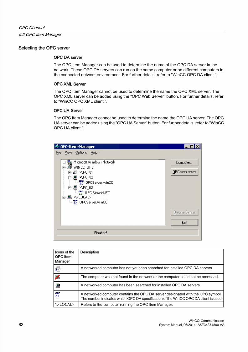
8/20/2019 WinCC Communication en-US en-US
http://slidepdf.com/reader/full/wincc-communication-en-us-en-us 82/527
Selecting the OPC server
OPC DA server
The OPC Item Manager can be used to determine the name of the OPC DA server in thenetwork. These OPC DA servers can run on the same computer or on different computers inthe connected network environment. For further details, refer to "WinCC OPC DA client ".
OPC XML Server
The OPC Item Manager cannot be used to determine the name the OPC XML server. TheOPC XML server can be added using the "OPC Web Server" button. For further details, referto "WinCC OPC XML client ".
OPC UA Server
The OPC Item Manager cannot be used to determine the name the OPC UA server. The OPC
UA server can be added using the "OPC UA Server" button. For further details, refer to "WinCCOPC UA client ".
Icons of the
OPC Item
Manager
Description
A networked computer has not yet been searched for installed OPC DA servers.
The computer was not found in the network or the computer could not be accessed.
A networked computer has been searched for installed OPC DA servers.
A networked computer contains the OPC DA server designated with the OPC symbol.The number indicates which OPC DA specification of the WinCC OPC DA client is used.
\\<LOCAL> Refers to the computer running the OPC Item Manager.
OPC Channel
5.2 OPC Item Manager
WinCC: Communication82 System Manual, 06/2014, A5E34374800-AA
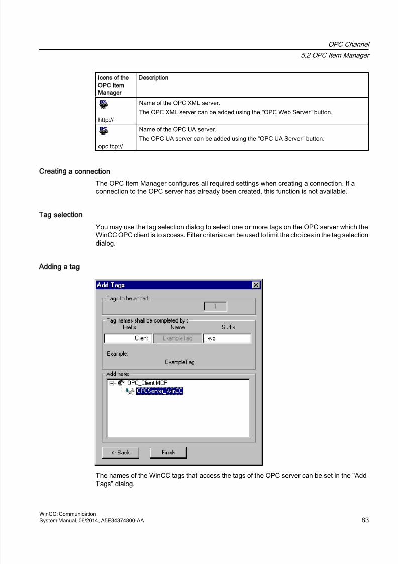
8/20/2019 WinCC Communication en-US en-US
http://slidepdf.com/reader/full/wincc-communication-en-us-en-us 83/527
Icons of the
OPC Item
Manager
Description
http://
Name of the OPC XML server.
The OPC XML server can be added using the "OPC Web Server" button.
opc.tcp://
Name of the OPC UA server.
The OPC UA server can be added using the "OPC UA Server" button.
Creating a connection
The OPC Item Manager configures all required settings when creating a connection. If aconnection to the OPC server has already been created, this function is not available.
Tag selection
You may use the tag selection dialog to select one or more tags on the OPC server which theWinCC OPC client is to access. Filter criteria can be used to limit the choices in the tag selectiondialog.
Adding a tag
The names of the WinCC tags that access the tags of the OPC server can be set in the "AddTags" dialog.
OPC Channel
5.2 OPC Item Manager
WinCC: CommunicationSystem Manual, 06/2014, A5E34374800-AA 83
8/20/2019 WinCC Communication en-US en-US
http://slidepdf.com/reader/full/wincc-communication-en-us-en-us 84/527
The WinCC tag name consists of the "prefix", "name" and "suffix". The "Name" field ispreconfigured with the "ExampleTag" text. "ExampleTag" stands for the WinCC tag name ofthe WinCC OPC server.
You can assign a prefix or suffix to distinguish the WinCC tag name on the WinCC OPC clientfrom the WinCC tag name on the WinCC OPC server. When configuring project monitoring, aprefix or suffix must be assigned.
The tag name may be assigned only once in a given WinCC project.
Example
The WinCC tag name on the WinCC OPC DA server is called "OPC_Server_Tag". The "Client_"value is entered in the prefix field and "_xyz" in the suffix field. In the WinCC project of theWinCC OPC DA client, the WinCC tag "Client_OPC_Server_Tag_xyz" is created.
If the tag name on the OPC server contains special characters, they are replaced by anunderscore ( "_" ), because not all special characters occurring in tag names are supportedby the OPC Item Manager.
Click "Finish" to add the WinCC tags to the WinCC project of the WinCC OPC DA client. TheOPC Item Manager automatically sets the data type, the name and the address parametersfor the WinCC tag.
See also
How to Access a WinCC Tag with the OPC Item Manager (Page 104)
How to Access a WinCC Tag with the OPC Item Manager (Page 87)
OPC Channel
5.2 OPC Item Manager
WinCC: Communication84 System Manual, 06/2014, A5E34374800-AA
8/20/2019 WinCC Communication en-US en-US
http://slidepdf.com/reader/full/wincc-communication-en-us-en-us 85/527
5.3 Overview of the Supported WinCC Data Types
The list below shows the data types that are supported by the WinCC OPC DA client and WinCC OPC
DA server:
● Binary tags
● Signed 8-bit value
● Unsigned 8-bit value
● Signed 16-bit value
● Unsigned 16-bit value
● Signed 32-bit value
● Unsigned 32-bit value● Floating-point number 32-bit IEEE 754
● Floating-point number 64-bit IEEE 754
● Text tag, 8-bit character set
● Text tag, 16-bit character set
● Raw data type
● Structure types
● Text reference
Note
For structure types, only the structure elements are supported, not the structure itself.However, the structure can be configured later. For more information, refer to the topic "Usingstructures on the WinCC OPC DA client."
If a text tag is created with the OPC Item Manager, it is assigned a length of 160 characters.This length can be changed to any length.
See also
How to Use Structures on the WinCC OPC DA Client (Page 95)
OPC Channel
5.3 Overview of the Supported WinCC Data Types
WinCC: CommunicationSystem Manual, 06/2014, A5E34374800-AA 85
8/20/2019 WinCC Communication en-US en-US
http://slidepdf.com/reader/full/wincc-communication-en-us-en-us 86/527
5.4 WinCC OPC DA Client
5.4.1 Functionality of the WinCC OPC DA Client
Introduction
The OPC channel does not require a separate communication module. The OPC channel isan application which employs the OPC software interface to use an OPC DA server to accessprocess data.
If WinCC is to be used as an OPC DA client, the OPC channel must be added to the WinCCproject.
If a communication is established to a WinCC OPC DA server, the values of the WinCC tagsare exchanged. To do this, a connection is set up in the WinCC project of the WinCC OPC DAclient; it is used to handle access to the WinCC OPC DA server.
For the WinCC OPC DA client to access multiple OPC DA servers, a connection for each ofthe OPC DA servers must be set up in the WinCC project. For more information abouttroubleshooting channels and tags, refer to "Troubleshooting".
Note
The WinCC OPC channel establishes connections only to OPC servers which have the status"OPC_STATUS_RUNNING".
Note
OPC channel
Unicode is not supported for connection names. Make sure that you name all connections inthe project in the same language. Open the Control Panel of your computer to set the codepage of this language for use in programs that do not support Unicode.
Connection Monitoring
Three mechanisms are integrated for connection monitoring in the WinCC OPC-DA client. Itis thus possible to take the best possible measures in the event of a network error ormalfunction of an OPC DA server.
1. If the processing period for a DCOM activation exceeds warning value of 5 seconds, thetag is assigned the value "Addressing Error". If the processing period exceeds thecancellation value of 10 seconds, the connection to the OPC DA server is interrupted. Thisis displayed in the "Connection Status" dialog of the WinCC Explorers.
The OPC DA specification 3.00 is provided with the "Keep-Alive" feature. If the OPC DA serversupports the OPC DA specifications 3.00, this feature is used. The feature causes the OPCDA server to automatically trigger cyclic updating (call OnDataChange) even if the tag valueshave not changed. If this regular updating is disabled, the WinCC OPC DA client terminatesthe connection.
OPC Channel
5.4 WinCC OPC DA Client
WinCC: Communication86 System Manual, 06/2014, A5E34374800-AA
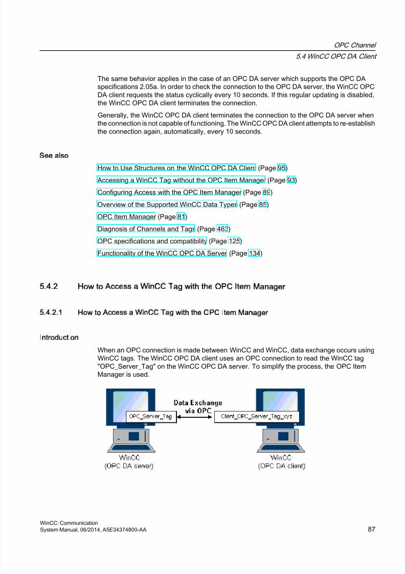
8/20/2019 WinCC Communication en-US en-US
http://slidepdf.com/reader/full/wincc-communication-en-us-en-us 87/527
The same behavior applies in the case of an OPC DA server which supports the OPC DAspecifications 2.05a. In order to check the connection to the OPC DA server, the WinCC OPCDA client requests the status cyclically every 10 seconds. If this regular updating is disabled,
the WinCC OPC DA client terminates the connection.
Generally, the WinCC OPC DA client terminates the connection to the OPC DA server whenthe connection is not capable of functioning. The WinCC OPC DA client attempts to re-establishthe connection again, automatically, every 10 seconds.
See also
How to Use Structures on the WinCC OPC DA Client (Page 95)
Accessing a WinCC Tag without the OPC Item Manager (Page 93)
Configuring Access with the OPC Item Manager (Page 89)
Overview of the Supported WinCC Data Types (Page 85)
OPC Item Manager (Page 81)
Diagnosis of Channels and Tags (Page 463)
OPC specifications and compatibility (Page 125)
Functionality of the WinCC OPC DA Server (Page 134)
5.4.2 How to Access a WinCC Tag with the OPC Item Manager
5.4.2.1 How to Access a WinCC Tag with the OPC Item Manager
Introduction
When an OPC connection is made between WinCC and WinCC, data exchange occurs usingWinCC tags. The WinCC OPC DA client uses an OPC connection to read the WinCC tag"OPC_Server_Tag" on the WinCC OPC DA server. To simplify the process, the OPC ItemManager is used.
OPC Channel
5.4 WinCC OPC DA Client
WinCC: CommunicationSystem Manual, 06/2014, A5E34374800-AA 87
8/20/2019 WinCC Communication en-US en-US
http://slidepdf.com/reader/full/wincc-communication-en-us-en-us 88/527
Requirements
● Two computers with WinCC projects.
● Both computers must be accessible via their IP addresses.
Configuration Steps
The following configurations are required in the WinCC project of the WinCC OPC DA client:
● Creation of a connection.
● Configuration of the "XMLClient_OPC_Var1_xyz" WinCC tag on the WinCC OPCXML clientwhich accesses the WinCC tag of the WinCC OPC DA server.
See also
Configuring Access with the OPC Item Manager (Page 89)
Configuring the OPC Channel on the WinCC OPC DA Client (Page 88)
Configuring Access with the OPC Item Manager (Page 105)
Example of WinCC to WinCC Connection (Page 137)
5.4.2.2 Configuring the OPC Channel on the WinCC OPC DA Client
Introduction
To use OPC for data exchange, the OPC channel must be set up in the WinCC project.
Procedure
1. Click the "Tag Management" icon in the navigation window of the WinCC Explorer on theWinCC OPC DA client.
2. Select "Add New Driver" from the "Tag Management" shortcut menu. The "Add New Driver"dialog is opened.
3. Select the "OPC.chn" driver and click the "Open" button. The channel is created and thecommunication driver is displayed in the tag management.
See also
Configuring Access with the OPC Item Manager (Page 89)
OPC Channel
5.4 WinCC OPC DA Client
WinCC: Communication88 System Manual, 06/2014, A5E34374800-AA
8/20/2019 WinCC Communication en-US en-US
http://slidepdf.com/reader/full/wincc-communication-en-us-en-us 89/527
5.4.2.3 Configuring Access with the OPC Item Manager
Introduction
This section explains how to use the OPC Item Manager to configure access to the WinCCtag "OPC_Server_Tag" of the WinCC OPC DA server.
Requirements
● Configure an internal tag named "OPC_Server_Tag" of the data type "signed 16-bit value"in the WinCC project of the WinCC OPC DA server.
● Enable the WinCC project of the WinCC OPC DA server.
● Add the "OPC" channel to the WinCC project of the WinCC OPC DA client.
Note
OPC channel
Unicode is not supported for connection names. Make sure that you name all connections inthe project in the same language. Open the Control Panel of your computer to set the codepage of this language for use in programs that do not support Unicode.
OPC Channel
5.4 WinCC OPC DA Client
WinCC: CommunicationSystem Manual, 06/2014, A5E34374800-AA 89
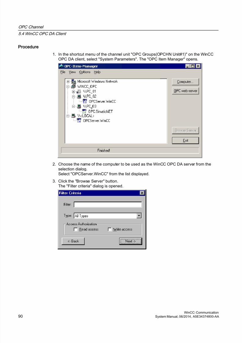
8/20/2019 WinCC Communication en-US en-US
http://slidepdf.com/reader/full/wincc-communication-en-us-en-us 90/527
Procedure
1. In the shortcut menu of the channel unit "OPC Groups(OPCHN Unit#1)" on the WinCC
OPC DA client, select "System Parameters". The "OPC Item Manager" opens.
2. Choose the name of the computer to be used as the WinCC OPC DA server from theselection dialog.Select "OPCServer.WinCC" from the list displayed.
3. Click the "Browse Server" button.The "Filter criteria" dialog is opened.
OPC Channel
5.4 WinCC OPC DA Client
WinCC: Communication90 System Manual, 06/2014, A5E34374800-AA
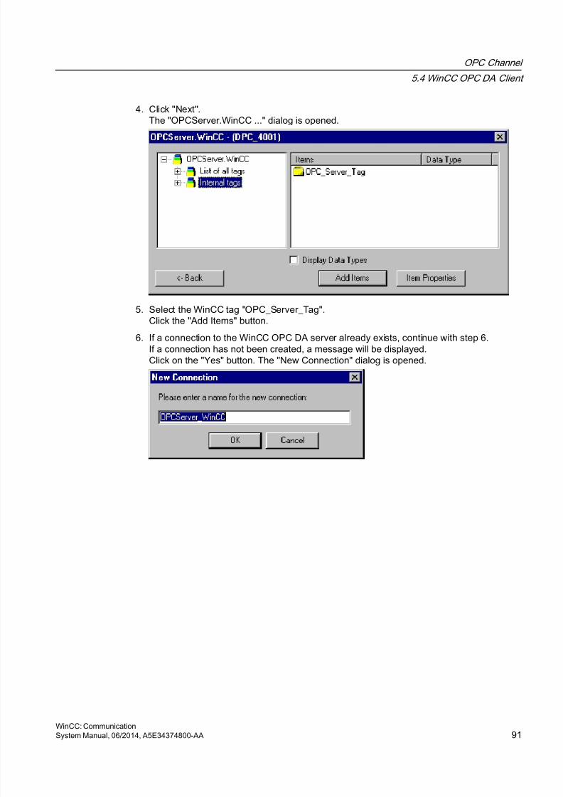
8/20/2019 WinCC Communication en-US en-US
http://slidepdf.com/reader/full/wincc-communication-en-us-en-us 91/527
4. Click "Next".The "OPCServer.WinCC ..." dialog is opened.
5. Select the WinCC tag "OPC_Server_Tag".Click the "Add Items" button.
6. If a connection to the WinCC OPC DA server already exists, continue with step 6.If a connection has not been created, a message will be displayed.Click on the "Yes" button. The "New Connection" dialog is opened.
OPC Channel
5.4 WinCC OPC DA Client
WinCC: CommunicationSystem Manual, 06/2014, A5E34374800-AA 91
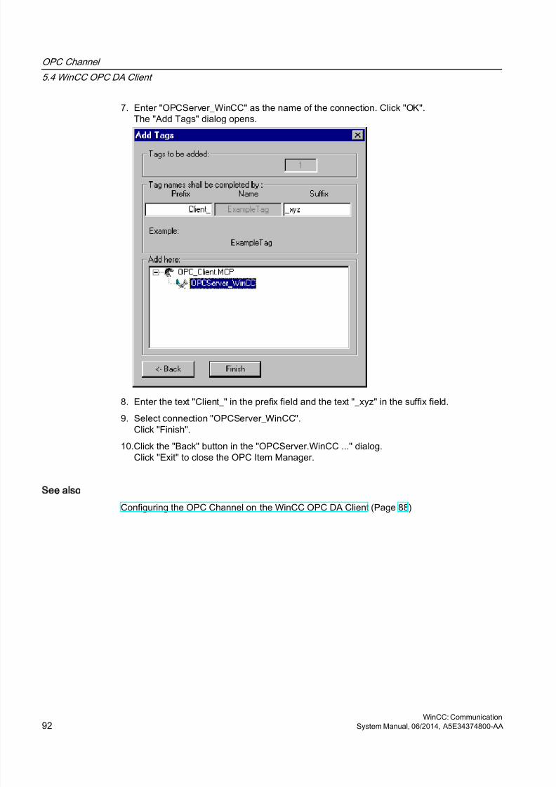
8/20/2019 WinCC Communication en-US en-US
http://slidepdf.com/reader/full/wincc-communication-en-us-en-us 92/527
7. Enter "OPCServer_WinCC" as the name of the connection. Click "OK".The "Add Tags" dialog opens.
8. Enter the text "Client_" in the prefix field and the text "_xyz" in the suffix field.
9. Select connection "OPCServer_WinCC".Click "Finish".
10.Click the "Back" button in the "OPCServer.WinCC ..." dialog.Click "Exit" to close the OPC Item Manager.
See also
Configuring the OPC Channel on the WinCC OPC DA Client (Page 88)
OPC Channel
5.4 WinCC OPC DA Client
WinCC: Communication92 System Manual, 06/2014, A5E34374800-AA
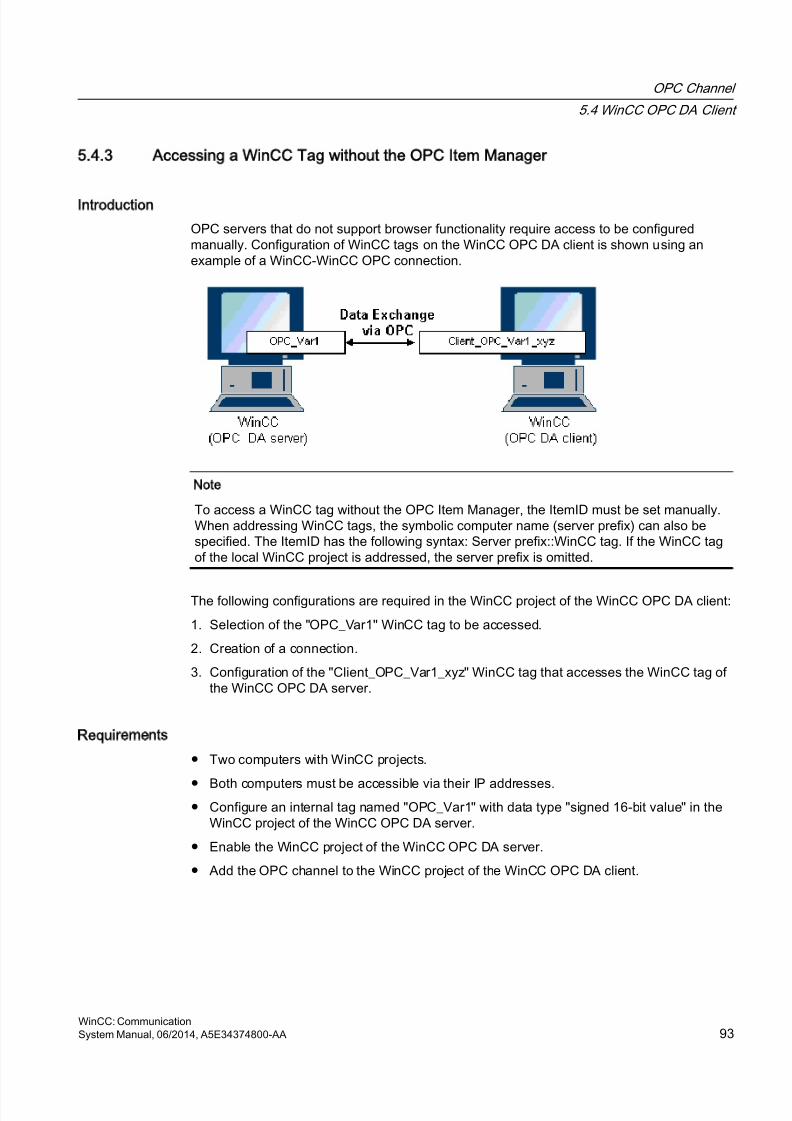
8/20/2019 WinCC Communication en-US en-US
http://slidepdf.com/reader/full/wincc-communication-en-us-en-us 93/527
5.4.3 Accessing a WinCC Tag without the OPC Item Manager
Introduction
OPC servers that do not support browser functionality require access to be configuredmanually. Configuration of WinCC tags on the WinCC OPC DA client is shown using anexample of a WinCC-WinCC OPC connection.
Note
To access a WinCC tag without the OPC Item Manager, the ItemID must be set manually.When addressing WinCC tags, the symbolic computer name (server prefix) can also bespecified. The ItemID has the following syntax: Server prefix::WinCC tag. If the WinCC tagof the local WinCC project is addressed, the server prefix is omitted.
The following configurations are required in the WinCC project of the WinCC OPC DA client:
1. Selection of the "OPC_Var1" WinCC tag to be accessed.
2. Creation of a connection.
3. Configuration of the "Client_OPC_Var1_xyz" WinCC tag that accesses the WinCC tag ofthe WinCC OPC DA server.
Requirements
● Two computers with WinCC projects.
● Both computers must be accessible via their IP addresses.● Configure an internal tag named "OPC_Var1" with data type "signed 16-bit value" in the
WinCC project of the WinCC OPC DA server.
● Enable the WinCC project of the WinCC OPC DA server.
● Add the OPC channel to the WinCC project of the WinCC OPC DA client.
OPC Channel
5.4 WinCC OPC DA Client
WinCC: CommunicationSystem Manual, 06/2014, A5E34374800-AA 93
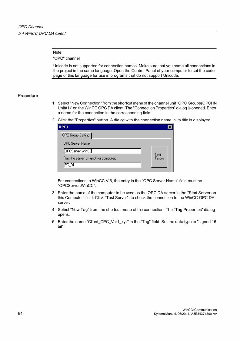
8/20/2019 WinCC Communication en-US en-US
http://slidepdf.com/reader/full/wincc-communication-en-us-en-us 94/527
Note
OPC channel
Unicode is not supported for connection names. Make sure that you name all connections inthe project in the same language. Open the Control Panel of your computer to set the codepage of this language for use in programs that do not support Unicode.
Procedure
1. Select "New Connection" from the shortcut menu of the channel unit "OPC Groups(OPCHNUnit#1)" on the WinCC OPC DA client. The "Connection Properties" dialog is opened. Entera name for the connection in the corresponding field.
2. Click the "Properties" button. A dialog with the connection name in its title is displayed.
For connections to WinCC V 6, the entry in the "OPC Server Name" field must be"OPCServer.WinCC".
3. Enter the name of the computer to be used as the OPC DA server in the "Start Server onthis Computer" field. Click "Test Server", to check the connection to the WinCC OPC DAserver.
4. Select "New Tag" from the shortcut menu of the connection. The "Tag Properties" dialogopens.
5. Enter the name "Client_OPC_Var1_xyz" in the "Tag" field. Set the data type to "signed 16-bit".
OPC Channel
5.4 WinCC OPC DA Client
WinCC: Communication94 System Manual, 06/2014, A5E34374800-AA
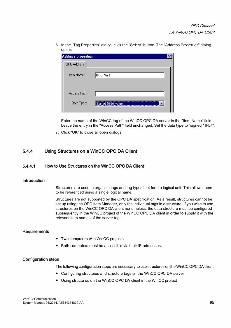
8/20/2019 WinCC Communication en-US en-US
http://slidepdf.com/reader/full/wincc-communication-en-us-en-us 95/527
6. In the "Tag Properties" dialog, click the "Select" button. The "Address Properties" dialogopens.
Enter the name of the WinCC tag of the WinCC OPC DA server in the "Item Name" field.Leave the entry in the "Access Path" field unchanged. Set the data type to "signed 16-bit".
7. Click "OK" to close all open dialogs.
5.4.4 Using Structures on a WinCC OPC DA Client
5.4.4.1 How to Use Structures on the WinCC OPC DA Client
Introduction
Structures are used to organize tags and tag types that form a logical unit. This allows themto be referenced using a single logical name.
Structures are not supported by the OPC DA specification. As a result, structures cannot beset up using the OPC Item Manager, only the individual tags in a structure. If you wish to usestructures on the WinCC OPC DA client nonetheless, the data structure must be configuredsubsequently in the WinCC project of the WinCC OPC DA client in order to supply it with therelevant item names of the server tags.
Requirements
● Two computers with WinCC projects.
● Both computers must be accessible via their IP addresses.
Configuration steps
The following configuration steps are necessary to use structures on the WinCC OPC DA client:
● Configuring structures and structure tags on the WinCC OPC DA server
● Using structures on the WinCC OPC DA client in the WinCC project
OPC Channel
5.4 WinCC OPC DA Client
WinCC: CommunicationSystem Manual, 06/2014, A5E34374800-AA 95
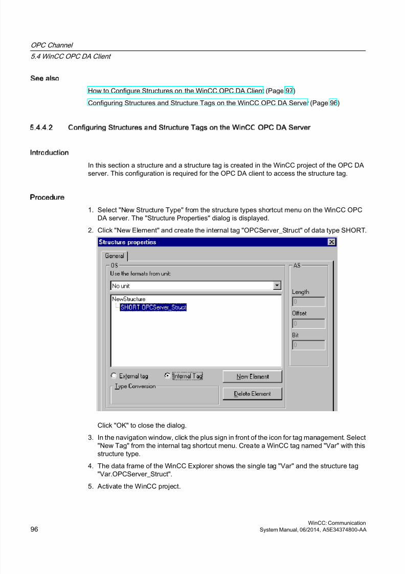
8/20/2019 WinCC Communication en-US en-US
http://slidepdf.com/reader/full/wincc-communication-en-us-en-us 96/527
See also
How to Configure Structures on the WinCC OPC DA Client (Page 97)
Configuring Structures and Structure Tags on the WinCC OPC DA Server (Page 96)
5.4.4.2 Configuring Structures and Structure Tags on the WinCC OPC DA Server
Introduction
In this section a structure and a structure tag is created in the WinCC project of the OPC DAserver. This configuration is required for the OPC DA client to access the structure tag.
Procedure
1. Select "New Structure Type" from the structure types shortcut menu on the WinCC OPCDA server. The "Structure Properties" dialog is displayed.
2. Click "New Element" and create the internal tag "OPCServer_Struct" of data type SHORT.
Click "OK" to close the dialog.
3. In the navigation window, click the plus sign in front of the icon for tag management. Select"New Tag" from the internal tag shortcut menu. Create a WinCC tag named "Var" with thisstructure type.
4. The data frame of the WinCC Explorer shows the single tag "Var" and the structure tag"Var.OPCServer_Struct".
5. Activate the WinCC project.
OPC Channel
5.4 WinCC OPC DA Client
WinCC: Communication96 System Manual, 06/2014, A5E34374800-AA

8/20/2019 WinCC Communication en-US en-US
http://slidepdf.com/reader/full/wincc-communication-en-us-en-us 97/527
See also
How to Configure Structures on the WinCC OPC DA Client (Page 97)
5.4.4.3 How to Configure Structures on the WinCC OPC DA Client
Introduction
Structures are not supported by the OPC DA specification. As a result, structures cannot beset up using the OPC Item Manager. In this section, the structure already present in the WinCCproject of the WinCC OPC DA server is configured for the WinCC project of the WinCC OPCDA client. A WinCC tag that accesses the existing structure tag on the WinCC OPC DA serveris configured on the WinCC OPC DA client.
Requirements
● Create a structure and a structure tag named "Var.OPCServer_Struct" in the WinCC projectof the WinCC OPC DA server.
● Enable the WinCC project of the WinCC OPC DA server.
● Add the OPC channel to the WinCC project of the WinCC OPC DA client.
Note
OPC channel
Unicode is not supported for connection names. Make sure that you name all connections inthe project in the same language. Open the Control Panel of your computer to set the codepage of this language for use in programs that do not support Unicode.
Procedure
1. Select "New Structure Type" from the structure types shortcut menu on the WinCC OPCDA client. The "Structure Properties" dialog is displayed.
2. Click the "New Element" button and set up an external tag. Name the element exactly asit is in the WinCC project of the OPC-DA server. Click "OK" to close the "Structure
Properties" dialog.3. If a connection to the OPC DA server already exists, continue with step 6.
If no connection has been created, select "New Connection" from the shortcut menu of thechannel unit "OPC". The "Connection Properties" dialog is opened. Enter a name for theconnection in the corresponding field.
4. Click the "Properties" button. A dialog with the connection name in its title is displayed. Forconnections to WinCC V 6, the entry in the field "OPC Server Name" must be"OPCServer.WinCC".
5. Enter the name of the computer to be used as the WinCC OPC DA server in the field "StartServer on this Computer". Click "Test Server", to check the connection to the WinCC OPCDA server. Click "OK" to close the dialog.
OPC Channel
5.4 WinCC OPC DA Client
WinCC: CommunicationSystem Manual, 06/2014, A5E34374800-AA 97
8/20/2019 WinCC Communication en-US en-US
http://slidepdf.com/reader/full/wincc-communication-en-us-en-us 98/527
6. Select "New Tag" from the shortcut menu of the connection. The "Tag Properties" dialogopens. Select the newly created structure type as the data type.
7. In the "Tag Properties" dialog, click the "Select" button. The "Address properties" dialogopens.In the "Item Name" field, enter the name "Var.OPCServer_Struct" for the structure tag ofthe WinCC OPC DA server. Leave the entry in the "Access Path" field unchanged.
8. Click "OK" to close all open dialogs.
See also
Configuring the OPC Channel on the WinCC OPC DA Client (Page 88)
Configuring Structures and Structure Tags on the WinCC OPC DA Server (Page 96)
5.4.5 Error Handling in the Event of Disturbed OPC DA Communication
5.4.5.1 Error Handling in the Event of Disturbed OPC Communication
Introduction
The procedure for communication testing is independent of how WinCC is used.
WinCC Used as the OPC DA Server
Use the channel diagnostics on the WinCC OPC DA client to determine whether a connectionto the OPC DA server can be established. For more information regarding channel problemanalysis, refer to "Troubleshooting".
WinCC Used as the OPC DA Client
Use the channel diagnostics on the WinCC OPC DA client to determine whether a connectionto the OPC DA server can be established. For more information regarding channel problemanalysis, refer to "Troubleshooting".
See also
WinCC is used as the OPC DA client, and the connection is not established. (Page 102)
WinCC is used as the OPC DA client, and the connection is established. (Page 101)
WinCC is used as the OPC DA server, and the connection is not established. (Page 100)
WinCC is used as the OPC DA server, and the connection is established successfully. (Page 99)
Possibilities for Diagnosing the "OPC" Channel (Page 498)
OPC Channel
5.4 WinCC OPC DA Client
WinCC: Communication98 System Manual, 06/2014, A5E34374800-AA
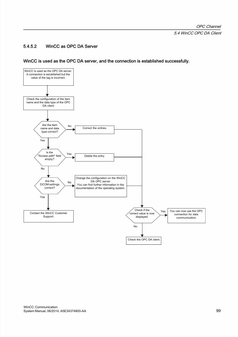
8/20/2019 WinCC Communication en-US en-US
http://slidepdf.com/reader/full/wincc-communication-en-us-en-us 99/527
5.4.5.2 WinCC as OPC DA Server
WinCC is used as the OPC DA server, and the connection is established successfully.
OPC Channel
5.4 WinCC OPC DA Client
WinCC: CommunicationSystem Manual, 06/2014, A5E34374800-AA 99
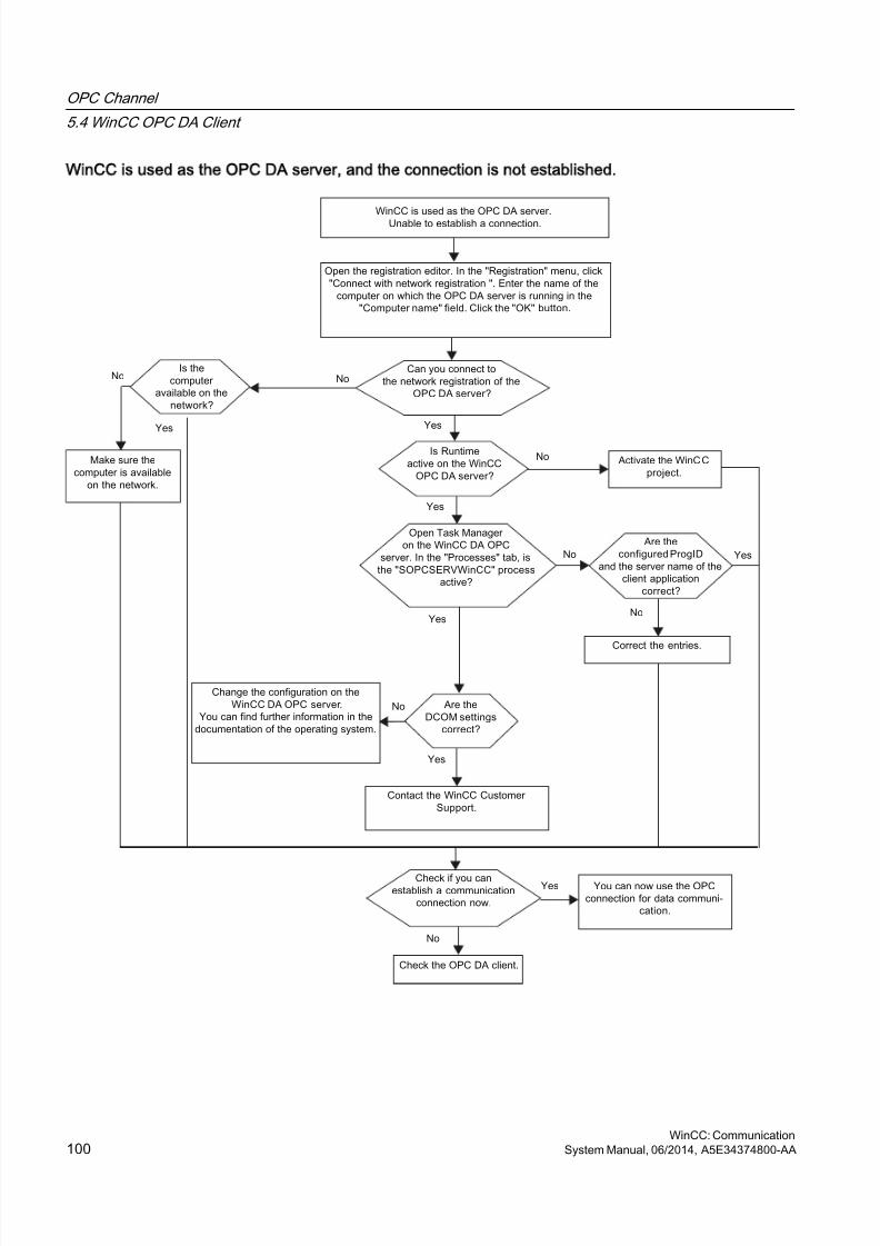
8/20/2019 WinCC Communication en-US en-US
http://slidepdf.com/reader/full/wincc-communication-en-us-en-us 100/527
WinCC is used as the OPC DA server, and the connection is not established.
OPC Channel
5.4 WinCC OPC DA Client
WinCC: Communication100 System Manual, 06/2014, A5E34374800-AA

8/20/2019 WinCC Communication en-US en-US
http://slidepdf.com/reader/full/wincc-communication-en-us-en-us 101/527
5.4.5.3 WinCC as OPC DA Client
WinCC is used as the OPC DA client, and the connection is established.
OPC Channel
5.4 WinCC OPC DA Client
WinCC: CommunicationSystem Manual, 06/2014, A5E34374800-AA 101
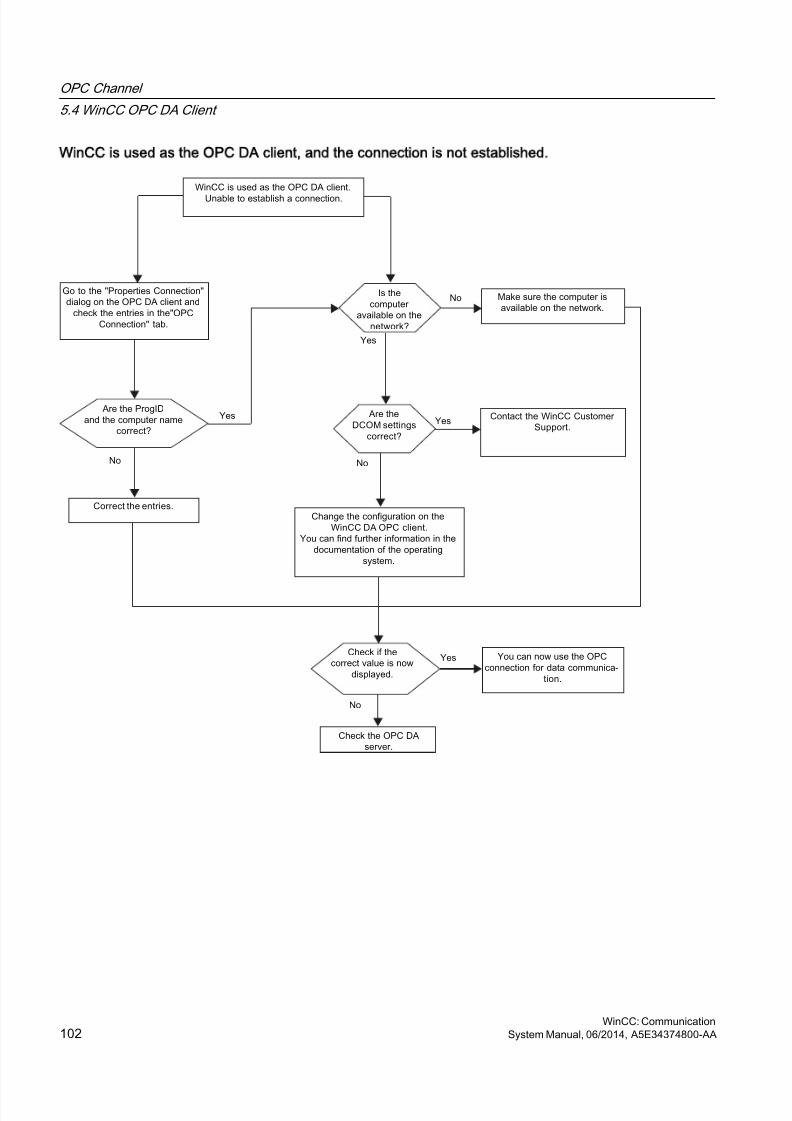
8/20/2019 WinCC Communication en-US en-US
http://slidepdf.com/reader/full/wincc-communication-en-us-en-us 102/527
WinCC is used as the OPC DA client, and the connection is not established.
OPC Channel
5.4 WinCC OPC DA Client
WinCC: Communication102 System Manual, 06/2014, A5E34374800-AA
8/20/2019 WinCC Communication en-US en-US
http://slidepdf.com/reader/full/wincc-communication-en-us-en-us 103/527
5.5 WinCC OPC XML Client
5.5.1 Functionality of the WinCC OPC XML Client
Introduction
The OPC channel does not require a separate communication module. The OPCcommunication driver can be implemented as the OPC XML client.
In order to use WinCC as the WinCC OPC XML client, the OPC channel must be added to theWinCC project.
The WinCC OPC XML client provides the OPC XML server with the OPC process data as a
web page. Access can be made to the web page via the Internet / Intranet using HTTP. Whena WinCC OPC XML client requests data, the web service is automatically started by the webserver.
In order that the WinCC OPC XML client can access several OPC XML servers, a connectionmust be made to each OPC XML server in the WinCC project.
If a communication is established to a WinCC OPC XML server, the values of the WinCC tagsare exchanged. A connection is set up in the WinCC project of the WinCC OPC XML client viawhich access to the WinCC OPC XML server can be processed. The connection monitoringis not activated in the case of a WinCC OPC XML client.
NOTICE
Operation with multiple network adapters and activated TCP/IP
For operation with multiple network adapters and activated TCP/IP protocol, observe theinformation in sections "WinCC Release Notes/Notes on Operation/Network Technology andUPS" and "Configurations/Distributed Systems/System Behavior in Runtime/SpecialFeatures of Communication using the Server with Several Network Adapters".
Note
The WinCC OPC channel establishes connections only to OPC servers which have the status"OPC_STATUS_RUNNING".
Note
OPC channel
Unicode is not supported for connection names. Make sure that you name all connections inthe project in the same language. Open the Control Panel of your computer to set the codepage of this language for use in programs that do not support Unicode.
OPC Channel
5.5 WinCC OPC XML Client
WinCC: CommunicationSystem Manual, 06/2014, A5E34374800-AA 103
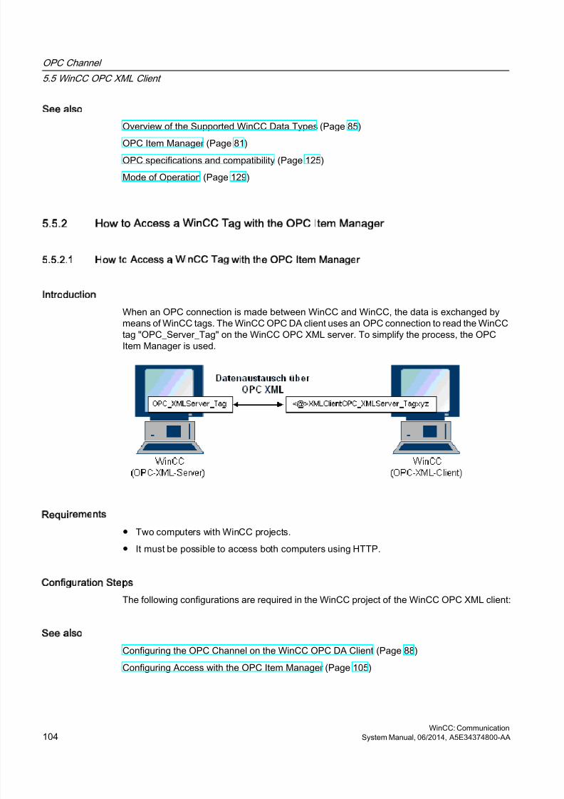
8/20/2019 WinCC Communication en-US en-US
http://slidepdf.com/reader/full/wincc-communication-en-us-en-us 104/527
See also
Overview of the Supported WinCC Data Types (Page 85)
OPC Item Manager (Page 81)
OPC specifications and compatibility (Page 125)
Mode of Operation (Page 129)
5.5.2 How to Access a WinCC Tag with the OPC Item Manager
5.5.2.1 How to Access a WinCC Tag with the OPC Item Manager
Introduction
When an OPC connection is made between WinCC and WinCC, the data is exchanged bymeans of WinCC tags. The WinCC OPC DA client uses an OPC connection to read the WinCCtag "OPC_Server_Tag" on the WinCC OPC XML server. To simplify the process, the OPCItem Manager is used.
Requirements
● Two computers with WinCC projects.
● It must be possible to access both computers using HTTP.
Configuration Steps
The following configurations are required in the WinCC project of the WinCC OPC XML client:
See also
Configuring the OPC Channel on the WinCC OPC DA Client (Page 88)
Configuring Access with the OPC Item Manager (Page 105)
OPC Channel
5.5 WinCC OPC XML Client
WinCC: Communication104 System Manual, 06/2014, A5E34374800-AA
8/20/2019 WinCC Communication en-US en-US
http://slidepdf.com/reader/full/wincc-communication-en-us-en-us 105/527
5.5.2.2 Configuring Access with the OPC Item Manager
Introduction
This section explains how to use the OPC Item Manager to configure access to the"OPC_XMLServer_Tag" WinCC tag of the WinCC OPC XML server.
Requirements
● Configure an internal tag named "OPC_XMLServer_Tag" of data type "signed 16-bit value"in the WinCC project of the WinCC OPC XML server.
● Activate the WinCC project of the WinCC OPC XML server.
● The OPC channel must be added to the WinCC project of the WinCC OPC XML client.
Note
OPC channel
Unicode is not supported for connection names. Make sure that you name all connections inthe project in the same language. Open the Control Panel of your computer to set the codepage of this language for use in programs that do not support Unicode.
OPC Channel
5.5 WinCC OPC XML Client
WinCC: CommunicationSystem Manual, 06/2014, A5E34374800-AA 105
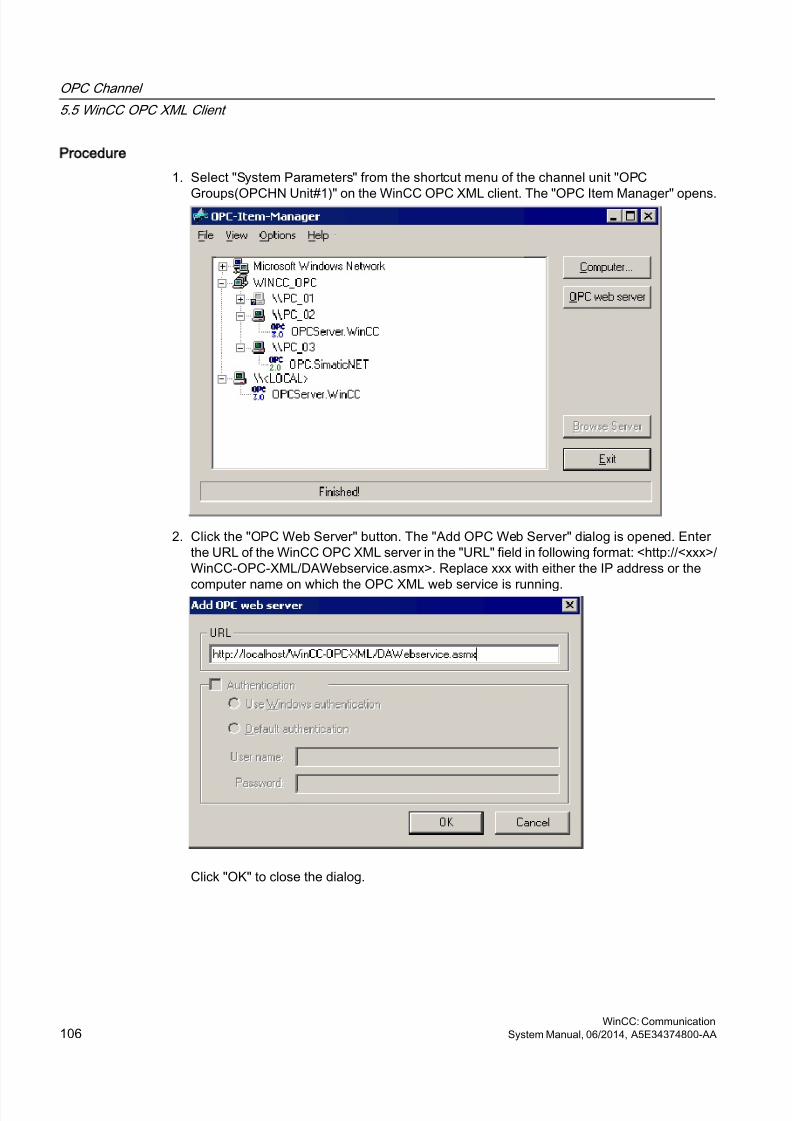
8/20/2019 WinCC Communication en-US en-US
http://slidepdf.com/reader/full/wincc-communication-en-us-en-us 106/527
Procedure
1. Select "System Parameters" from the shortcut menu of the channel unit "OPC
Groups(OPCHN Unit#1)" on the WinCC OPC XML client. The "OPC Item Manager" opens.
2. Click the "OPC Web Server" button. The "Add OPC Web Server" dialog is opened. Enterthe URL of the WinCC OPC XML server in the "URL" field in following format: <http://<xxx>/WinCC-OPC-XML/DAWebservice.asmx>. Replace xxx with either the IP address or the
computer name on which the OPC XML web service is running.
Click "OK" to close the dialog.
OPC Channel
5.5 WinCC OPC XML Client
WinCC: Communication106 System Manual, 06/2014, A5E34374800-AA
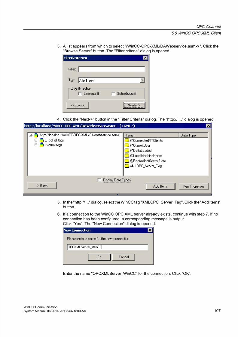
8/20/2019 WinCC Communication en-US en-US
http://slidepdf.com/reader/full/wincc-communication-en-us-en-us 107/527
3. A list appears from which to select "/WinCC-OPC-XML/DAWebservice.asmx>". Click the"Browse Server" button. The "Filter criteria" dialog is opened.
4. Click the "Next->" button in the "Filter Criteria" dialog. The "http:// ..." dialog is opened.
5. In the "http:// ..." dialog, select the WinCC tag "XMLOPC_Server_Tag". Click the "Add Items"button.
6. If a connection to the WinCC OPC XML server already exists, continue with step 7. If noconnection has been configured, a corresponding message is output.Click "Yes". The "New Connection" dialog is opened.
Enter the name "OPCXMLServer_WinCC" for the connection. Click "OK".
OPC Channel
5.5 WinCC OPC XML Client
WinCC: CommunicationSystem Manual, 06/2014, A5E34374800-AA 107
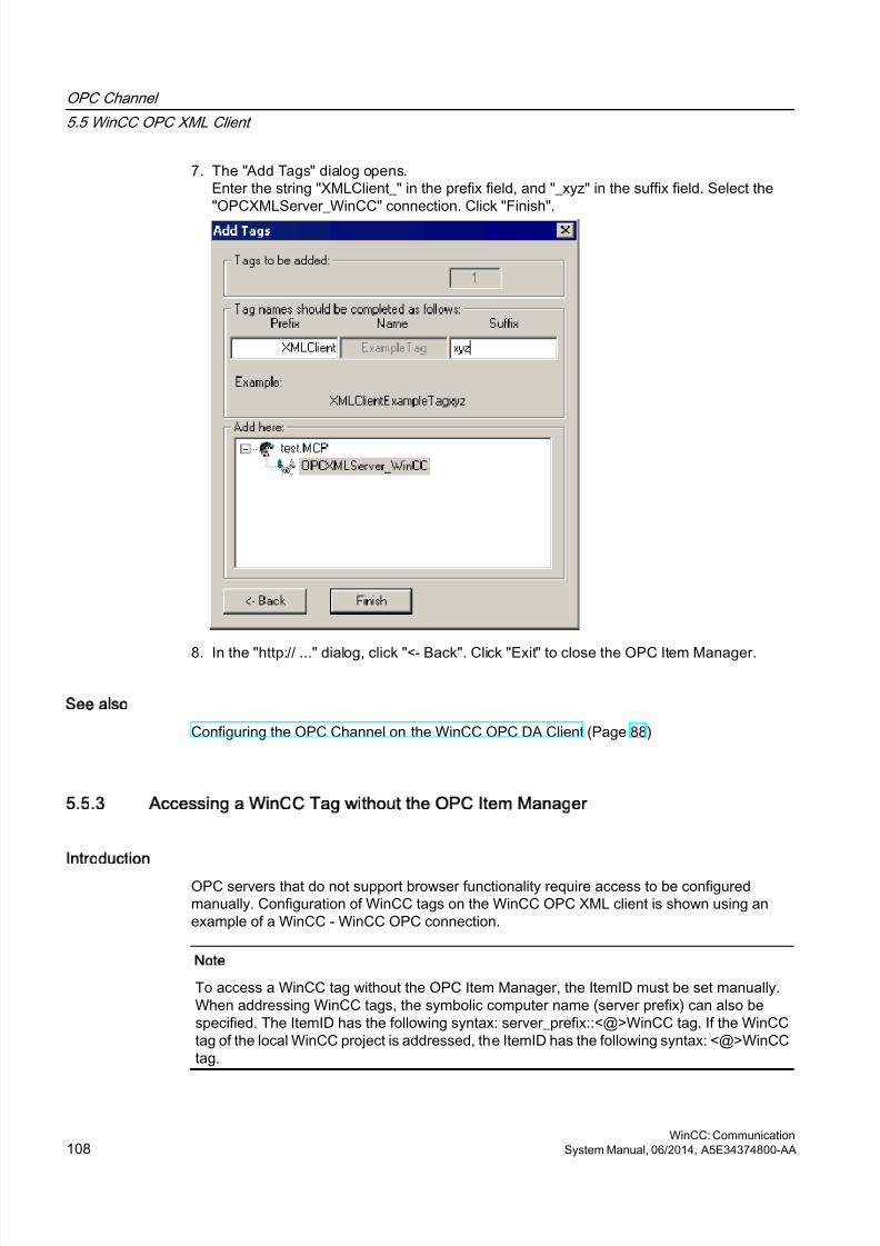
8/20/2019 WinCC Communication en-US en-US
http://slidepdf.com/reader/full/wincc-communication-en-us-en-us 108/527
7. The "Add Tags" dialog opens.Enter the string "XMLClient_" in the prefix field, and "_xyz" in the suffix field. Select the"OPCXMLServer_WinCC" connection. Click "Finish".
8. In the "http:// ..." dialog, click "<- Back". Click "Exit" to close the OPC Item Manager.
See also
Configuring the OPC Channel on the WinCC OPC DA Client (Page 88)
5.5.3 Accessing a WinCC Tag without the OPC Item Manager
Introduction
OPC servers that do not support browser functionality require access to be configuredmanually. Configuration of WinCC tags on the WinCC OPC XML client is shown using anexample of a WinCC - WinCC OPC connection.
Note
To access a WinCC tag without the OPC Item Manager, the ItemID must be set manually.When addressing WinCC tags, the symbolic computer name (server prefix) can also bespecified. The ItemID has the following syntax: server_prefix::<@>WinCC tag. If the WinCCtag of the local WinCC project is addressed, the ItemID has the following syntax: <@>WinCCtag.
OPC Channel
5.5 WinCC OPC XML Client
WinCC: Communication108 System Manual, 06/2014, A5E34374800-AA

8/20/2019 WinCC Communication en-US en-US
http://slidepdf.com/reader/full/wincc-communication-en-us-en-us 109/527
Configuration Steps
The following configurations are required in the WinCC project of the WinCC OPC XML client:
1. Creation of a connection.
2. Configuring the "XMLClient_OPC_Var1_xyz" WinCC tag on the WinCC OPC XML clientwhich accesses the WinCC tag of the WinCC OPC DA server.
Requirements
● Two computers with WinCC projects.
● It must be possible to access the computers using HTTP.
● Configure an internal tag named "XMLOPC_Server_Tag" with data type "signed 16-bitvalue" in the WinCC project of the WinCC OPC XML server.
● Enable the WinCC project of the WinCC OPC XML server.
● The OPC channel must be added to the WinCC project of the WinCC OPC XML client.
Note
When configuring external tags in the OPC channel, the preset values from WinCC in thetype conversion field of the "Tag Properties" dialog must not be altered. The data type ofthe tag in the process is set in the data type field of the "Address Properties" dialog.
Procedure
1. Select "New Connection" from the shortcut menu of the channel unit "OPC Groups(OPCHNUnit#1)" on the WinCC OPC XML client. The "Connection Properties" dialog is opened.Enter a name for the connection in the corresponding field.
2. Click the "Properties" button. A dialog with the connection name in its title is displayed.
Select the "XML DA Server" check box. In the case of a connection to the WinCC OPCXML server, the "OPC Server Name" field must contain the URL of the WinCC OPC XMLserver. The URL has the following syntax: "http://<xxx>/WinCC-OPC-XML/DAWebservice.asmx". Replace xxx with either the IP address or the computer name onwhich the OPC-XML web service is running.
OPC Channel
5.5 WinCC OPC XML Client
WinCC: CommunicationSystem Manual, 06/2014, A5E34374800-AA 109
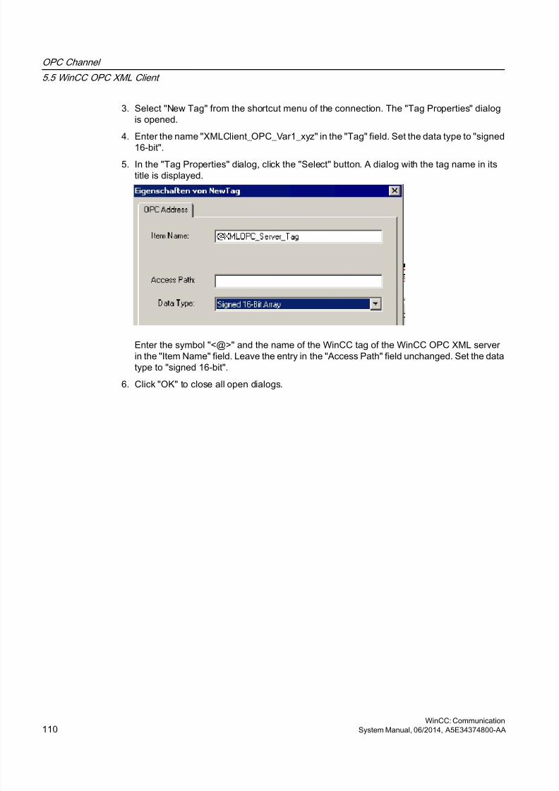
8/20/2019 WinCC Communication en-US en-US
http://slidepdf.com/reader/full/wincc-communication-en-us-en-us 110/527
3. Select "New Tag" from the shortcut menu of the connection. The "Tag Properties" dialogis opened.
4. Enter the name "XMLClient_OPC_Var1_xyz" in the "Tag" field. Set the data type to "signed16-bit".
5. In the "Tag Properties" dialog, click the "Select" button. A dialog with the tag name in itstitle is displayed.
Enter the symbol "<@>" and the name of the WinCC tag of the WinCC OPC XML serverin the "Item Name" field. Leave the entry in the "Access Path" field unchanged. Set the datatype to "signed 16-bit".
6. Click "OK" to close all open dialogs.
OPC Channel
5.5 WinCC OPC XML Client
WinCC: Communication110 System Manual, 06/2014, A5E34374800-AA
8/20/2019 WinCC Communication en-US en-US
http://slidepdf.com/reader/full/wincc-communication-en-us-en-us 111/527
5.6 WinCC OPC UA client
5.6.1 Functionality of the WinCC OPC UA client
Introduction
The WinCC OPC UA client enables data access to any OPC UA server in accordance withthe OPC Unified Architecture specification. OPC Unified Architecture (OPC UA) also providesadditional mechanisms such as authentication and encryption for secure communicationbetween participating partners.
To use WinCC as WinCC OPC UA client, add the OPC communication driver (OPC channel)to the WinCC project. A separate communication module is not required.
To enable access to the OPC process data of different OPC UA servers, configure a connectionto each server in the WinCC project. Use the WinCC OPC Item Manager to configure theconnections.
Note
Connection monitoring is not activated if the OPC channel is used as OPC UA client.
Connections are only established to servers which signal the status "RUNNING".
5.6.2 Accessing a tag using the OPC Item Manager
5.6.2.1 Accessing an OPC tag using the OPC Item Manager
Introduction
If there is an OPC link from WinCC to an OPC UA server, OPC UA server data is mapped toa WinCC tag. In this process, the WinCC OPC UA client uses a secure connection to accessthe "OPC_UAServer_Tag" of the WinCC OPC UA server. Use OPC Item Manager for yourconfiguration.
Note
You can only access servers that offer browse support during the configuration.
Distinguish between client and server certificates when configuring. Secure communicationis only possible when client and server recognize each other's certificates.
Certificates are linked to the respective computers. After having moved, copied, or duplicatedthe WinCC project to a different computer, repeat this procedure so that each computer canverify the other's certificates.
OPC Channel
5.6 WinCC OPC UA client
WinCC: CommunicationSystem Manual, 06/2014, A5E34374800-AA 111
8/20/2019 WinCC Communication en-US en-US
http://slidepdf.com/reader/full/wincc-communication-en-us-en-us 112/527
Requirements
● Client computers with a WinCC project.
● Both computers must be accessible via TCP connection.
● The Firewall allows two-way communication with the UA server.
Configuration Steps
Complete the following configuration tasks in the WinCC project of the WinCC OPC UA client:
● Configuration of the OPC channel on the WinCC OPC UA client.
● Setup of a valid server certificate.
● Configuration of access with the OPC Item Manager.
5.6.2.2 How to set up a server certificate
Introduction
This section explains how to set up an OPC UA server certificate for the WinCC OPC UA client.
Requirements
● The OPC UA server is activated.
● The Firewall allows two-way communication with the UA server.● The "OPC" channel has been added to the WinCC project of the WinCC OPC UA client.
OPC Channel
5.6 WinCC OPC UA client
WinCC: Communication112 System Manual, 06/2014, A5E34374800-AA
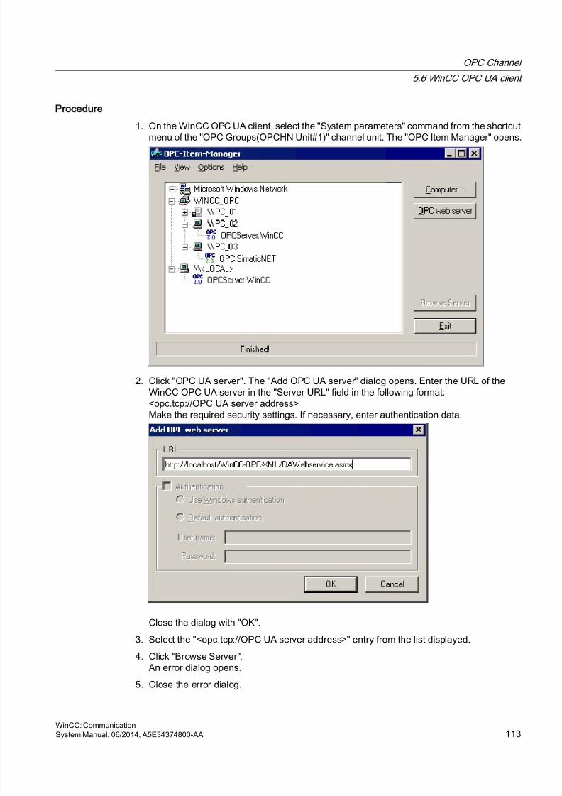
8/20/2019 WinCC Communication en-US en-US
http://slidepdf.com/reader/full/wincc-communication-en-us-en-us 113/527
Procedure
1. On the WinCC OPC UA client, select the "System parameters" command from the shortcut
menu of the "OPC Groups(OPCHN Unit#1)" channel unit. The "OPC Item Manager" opens.
2. Click "OPC UA server". The "Add OPC UA server" dialog opens. Enter the URL of theWinCC OPC UA server in the "Server URL" field in the following format:<opc.tcp://OPC UA server address>
Make the required security settings. If necessary, enter authentication data.
Close the dialog with "OK".
3. Select the "<opc.tcp://OPC UA server address>" entry from the list displayed.
4. Click "Browse Server".An error dialog opens.
5. Close the error dialog.
OPC Channel
5.6 WinCC OPC UA client
WinCC: CommunicationSystem Manual, 06/2014, A5E34374800-AA 113
8/20/2019 WinCC Communication en-US en-US
http://slidepdf.com/reader/full/wincc-communication-en-us-en-us 114/527
6. Open Windows Explorer and change to the "OPC" folder in the WinCC installation path.
7. Open the "PKI/CA/" folder.
The "rejected" folder containing the rejected server certificate has been added.8. Move the server certificate from the "rejected" folder to the "certs" folder.
The server certificate has been validated. It is now possible to activate a secure connectionto the OPC UA server.
5.6.2.3 How to configure access to a tag using the OPC Item Manager
Introduction
This section explains how to use OPC Item Manager to configure access to the
"OPC_UAServer_Tag" WinCC tag of the WinCC OPC UA server.
Note
You can only access servers that offer browse support during the configuration.
Requirements
● The OPC UA server is activated.
● The Firewall allows two-way communication with the UA server.
● The server certificate has been set up.● The "OPC" channel has been added to the WinCC project of the WinCC OPC UA client.
Note
OPC channel
Unicode is not supported for connection names. Make sure that you name all connections inthe project in the same language. Open the Control Panel of your computer to set the codepage of this language for use in programs that do not support Unicode.
OPC Channel
5.6 WinCC OPC UA client
WinCC: Communication114 System Manual, 06/2014, A5E34374800-AA
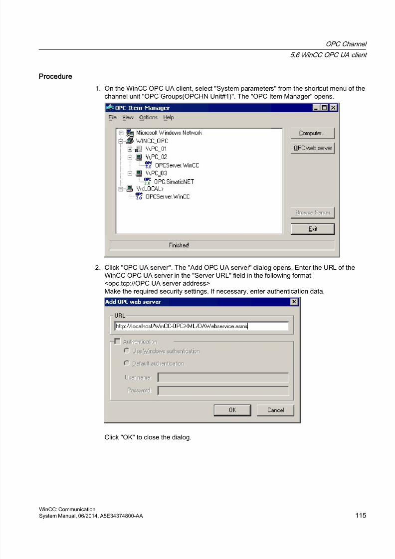
8/20/2019 WinCC Communication en-US en-US
http://slidepdf.com/reader/full/wincc-communication-en-us-en-us 115/527
Procedure
1. On the WinCC OPC UA client, select "System parameters" from the shortcut menu of the
channel unit "OPC Groups(OPCHN Unit#1)". The "OPC Item Manager" opens.
2. Click "OPC UA server". The "Add OPC UA server" dialog opens. Enter the URL of theWinCC OPC UA server in the "Server URL" field in the following format:<opc.tcp://OPC UA server address>
Make the required security settings. If necessary, enter authentication data.
Click "OK" to close the dialog.
OPC Channel
5.6 WinCC OPC UA client
WinCC: CommunicationSystem Manual, 06/2014, A5E34374800-AA 115
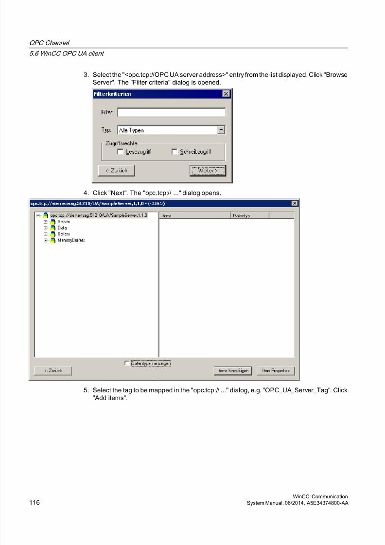
8/20/2019 WinCC Communication en-US en-US
http://slidepdf.com/reader/full/wincc-communication-en-us-en-us 116/527
3. Select the "<opc.tcp://OPC UA server address>" entry from the list displayed. Click "BrowseServer". The "Filter criteria" dialog is opened.
4. Click "Next". The "opc.tcp:// ..." dialog opens.
5. Select the tag to be mapped in the "opc.tcp:// ..." dialog, e.g. "OPC_UA_Server_Tag". Click"Add items".
OPC Channel
5.6 WinCC OPC UA client
WinCC: Communication116 System Manual, 06/2014, A5E34374800-AA
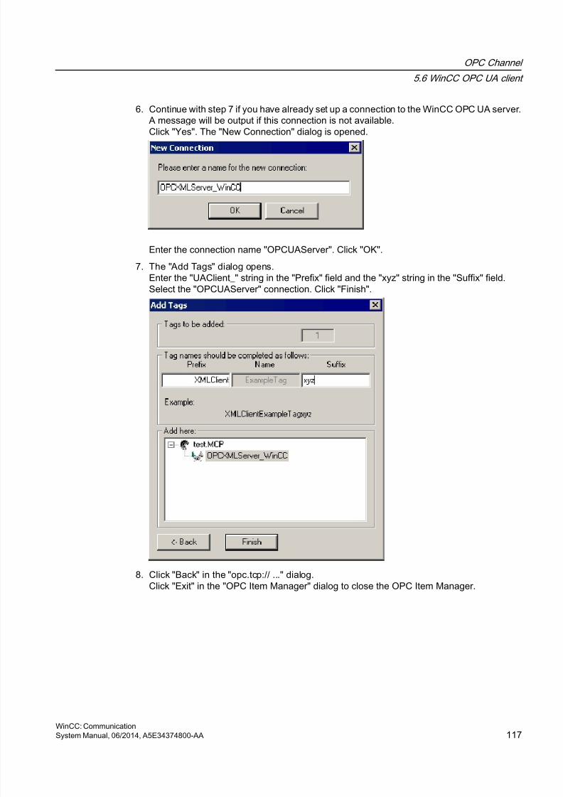
8/20/2019 WinCC Communication en-US en-US
http://slidepdf.com/reader/full/wincc-communication-en-us-en-us 117/527
6. Continue with step 7 if you have already set up a connection to the WinCC OPC UA server.A message will be output if this connection is not available.Click "Yes". The "New Connection" dialog is opened.
Enter the connection name "OPCUAServer". Click "OK".
7. The "Add Tags" dialog opens.
Enter the "UAClient_" string in the "Prefix" field and the "xyz" string in the "Suffix" field.Select the "OPCUAServer" connection. Click "Finish".
8. Click "Back" in the "opc.tcp:// ..." dialog.Click "Exit" in the "OPC Item Manager" dialog to close the OPC Item Manager.
OPC Channel
5.6 WinCC OPC UA client
WinCC: CommunicationSystem Manual, 06/2014, A5E34374800-AA 117
8/20/2019 WinCC Communication en-US en-US
http://slidepdf.com/reader/full/wincc-communication-en-us-en-us 118/527
5.6.3 Error handling in event of disturbed communication
Introduction
The procedure for communication testing is independent of how WinCC is used.
WinCC used as OPC UA server
First, run the channel diagnostics on the WinCC OPC UA client to check whether it is possibleto set up a connection to the OPC UA server. For more information regarding channel problemanalysis, refer to "Troubleshooting".
WinCC used as OPC UA client
First, run the channel diagnostics on the WinCC OPC UA client to check whether it is possibleto set up a connection to the OPC UA server. For more information regarding channel problemanalysis, refer to "Troubleshooting".
OPC Channel
5.6 WinCC OPC UA client
WinCC: Communication118 System Manual, 06/2014, A5E34374800-AA
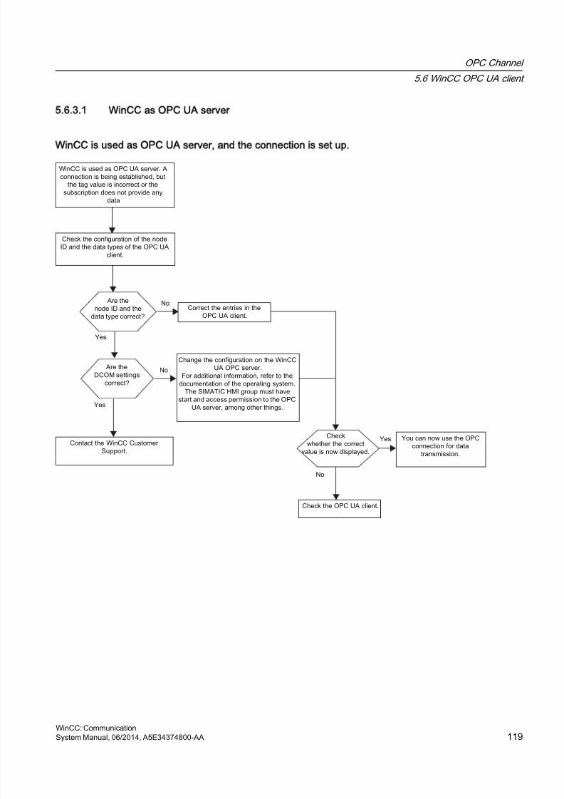
8/20/2019 WinCC Communication en-US en-US
http://slidepdf.com/reader/full/wincc-communication-en-us-en-us 119/527
5.6.3.1 WinCC as OPC UA server
WinCC is used as OPC UA server, and the connection is set up.
OPC Channel
5.6 WinCC OPC UA client
WinCC: CommunicationSystem Manual, 06/2014, A5E34374800-AA 119
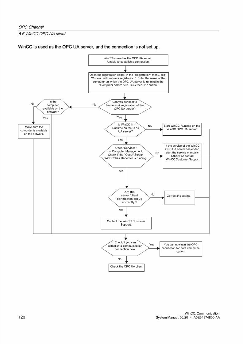
8/20/2019 WinCC Communication en-US en-US
http://slidepdf.com/reader/full/wincc-communication-en-us-en-us 120/527
WinCC is used as the OPC UA server, and the connection is not set up.
OPC Channel
5.6 WinCC OPC UA client
WinCC: Communication120 System Manual, 06/2014, A5E34374800-AA
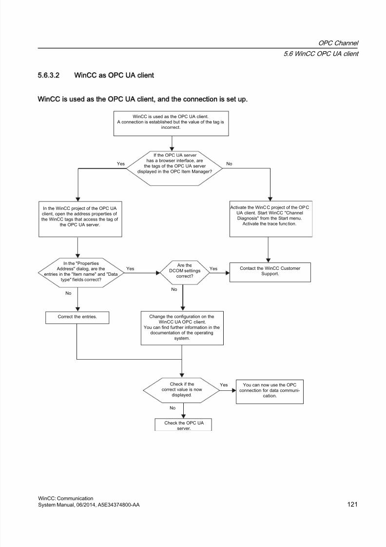
8/20/2019 WinCC Communication en-US en-US
http://slidepdf.com/reader/full/wincc-communication-en-us-en-us 121/527
5.6.3.2 WinCC as OPC UA client
WinCC is used as the OPC UA client, and the connection is set up.
OPC Channel
5.6 WinCC OPC UA client
WinCC: CommunicationSystem Manual, 06/2014, A5E34374800-AA 121
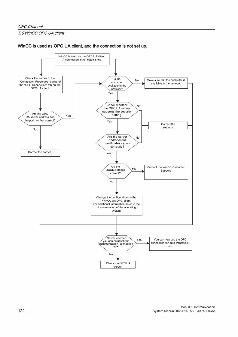
8/20/2019 WinCC Communication en-US en-US
http://slidepdf.com/reader/full/wincc-communication-en-us-en-us 122/527
WinCC is used as OPC UA client, and the connection is not set up.
OPC Channel
5.6 WinCC OPC UA client
WinCC: Communication122 System Manual, 06/2014, A5E34374800-AA
8/20/2019 WinCC Communication en-US en-US
http://slidepdf.com/reader/full/wincc-communication-en-us-en-us 123/527
OPC - Open Connectivity
6
6.1 OPC - Open Connectivity
Contents
The OPC standard software interface allows devices and applications from variousmanufacturers to be combined with one another in a uniform manner.
WinCC can be used as an OPC server or an OPC client. The "OPC" channel represents theOPC client application of WinCC.
This chapter describes
● the OPC servers of WinCC
● how to use OPC in WinCC
● how to set up various OPC DA links
● how to configure the access to the WinCC message system
● how the WinCC message system appears on the OPC A&E
● how to set up access to the WinCC archive system
WinCC: CommunicationSystem Manual, 06/2014, A5E34374800-AA 123
8/20/2019 WinCC Communication en-US en-US
http://slidepdf.com/reader/full/wincc-communication-en-us-en-us 124/527
6.2 Functionality of OPC
OPC is a standardized manufacturer-independent software interface for data exchange in
automation engineering.OPC interfaces allow the standard linking of devices and applications from differentmanufacturers.OPC is based on the Windows COM (Component Object Model) and DCOM (DistributedComponent Object Model) technologies.
OPC XML DA provides an additional software interface that is based on the XML, SOAP andHTTP Internet standards.
OPC UA (Unified Architecture) is the successor technology to OPC. OPC UA is platform-independent and supports different protocols as communication medium.
OPC - Open Connectivity
6.2 Functionality of OPC
WinCC: Communication124 System Manual, 06/2014, A5E34374800-AA

8/20/2019 WinCC Communication en-US en-US
http://slidepdf.com/reader/full/wincc-communication-en-us-en-us 125/527
6.3 OPC specifications and compatibility
Overview
OPC specifies the interfaces for access to the following objects in WinCC:
● Process values (OPC Data Access 2.05a, 3.0; OPC XML Data Access 1.01; OPC UA 1.02)
● Archived process values (OPC Historical Data Access 1.20; OPC UA 1.02)
● Chronological messages (OPC Historical Alarms and Events v1.10
● Messages (OPC Alarms and Events 1.10; OPC UA 1.02)
For more information about individual OPC specifications, refer to the OPC Foundationwebsite.
Compatibility
Support of these specifications is regularly monitored by the "Compliance Test Tool" (CTT) ofthe OPC Foundation. Interoperability with OPC products from other manufacturers isguaranteed by participation in "OPC Interoperability Workshops".
The test results submitted are published on the OPC Foundation website. To view the results,enter the search term "OPC Self-Certified Products".
See also
www.opcfoundation.org (http://www.opcfoundation.org)
OPC - Open Connectivity
6.3 OPC specifications and compatibility
WinCC: CommunicationSystem Manual, 06/2014, A5E34374800-AA 125
8/20/2019 WinCC Communication en-US en-US
http://slidepdf.com/reader/full/wincc-communication-en-us-en-us 126/527
6.4 Using OPC in WinCC
Introduction
In WinCC, servers are available for the following OPC interfaces:
● OPC Data Access / OPC XML Data Access: Access to the WinCC body of data
● OPC Historical Data Access: Access to the WinCC archive system
● OPC Alarms&Events: Access to the WinCC message system
● OPC Unified Architecture: Access to the WinCC body of data and archive system
WinCC contains an OPC channel by default. The OPC channel can access the relevant OPCservers as client via OPC DA , OPC XML DA or OPC UA.
WinCC OPC communications concept
Data exchange between a WinCC OPC server and OPC client is completed via DCOM. Afterinstallation of WinCC, the DCOM settings of the WinCC OPC server are correctly configured.
If a WinCC OPC server or client communicates with an external OPC system, correspondingadaptations must be performed. The "Local access" and "Remote access" authorizations mustbe entered for the user in "DCOM/Workplace/COM Security/Access rights/Edit default" of UserAdministration on the client.
The OPC XML server of WinCC is implemented as a web service. This gives you access toyour PC via the Internet. You therefore need to define appropriate access rights.
The following shows the WinCC OPC communication concept:
OPC - Open Connectivity
6.4 Using OPC in WinCC
WinCC: Communication126 System Manual, 06/2014, A5E34374800-AA
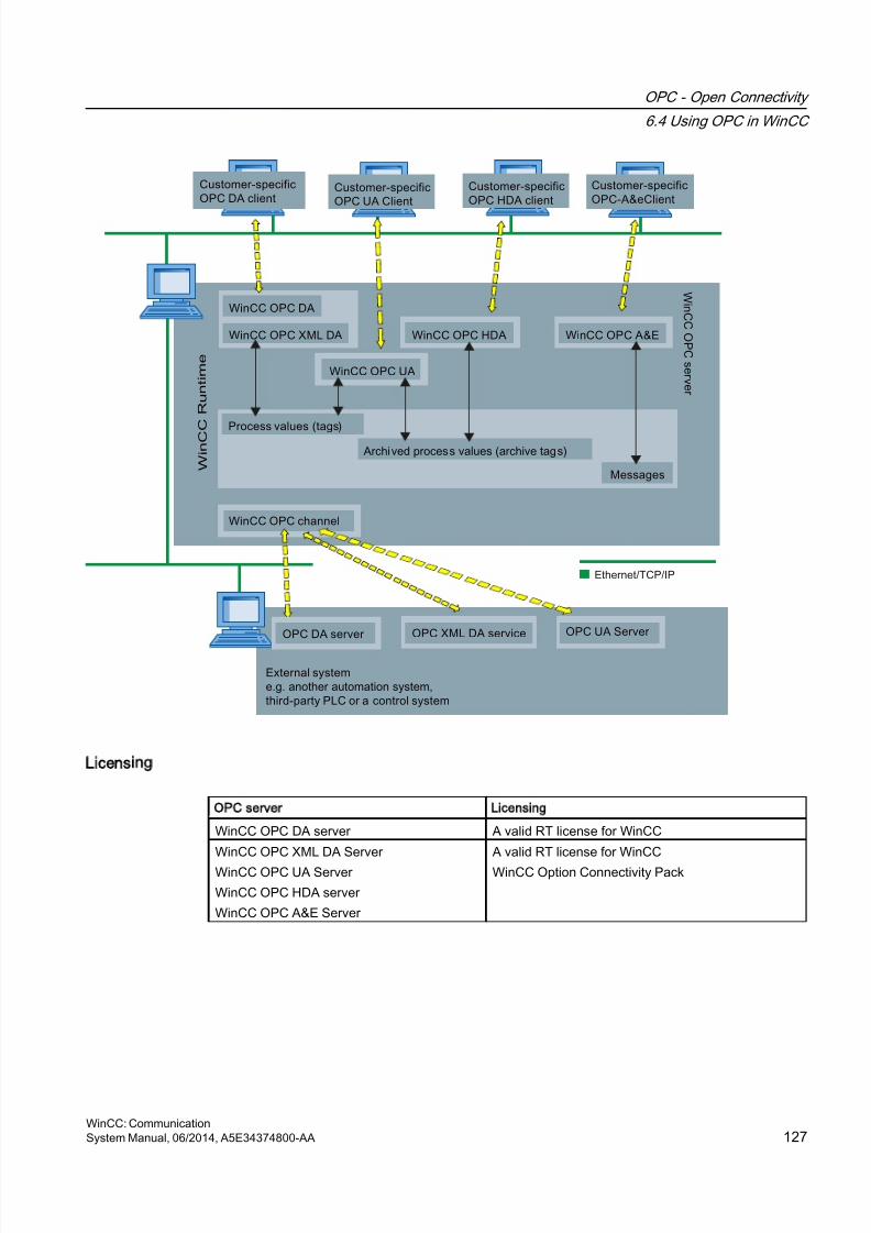
8/20/2019 WinCC Communication en-US en-US
http://slidepdf.com/reader/full/wincc-communication-en-us-en-us 127/527
Licensing
OPC server Licensing
WinCC OPC DA server A valid RT license for WinCC
WinCC OPC XML DA Server
WinCC OPC UA Server
WinCC OPC HDA server
WinCC OPC A&E Server
A valid RT license for WinCC
WinCC Option Connectivity Pack
OPC - Open Connectivity
6.4 Using OPC in WinCC
WinCC: CommunicationSystem Manual, 06/2014, A5E34374800-AA 127
8/20/2019 WinCC Communication en-US en-US
http://slidepdf.com/reader/full/wincc-communication-en-us-en-us 128/527
6.5 How to configure Windows for the use of WinCC OPC
Introduction
The OPC client and the OPC server are DCOM applications. A distributed DCOM applicationcan only be run under the same user account. Therefore the OPC server must recognize theOPC client's user account and vice-versa. If the WinCC OPC servers are used with WinCCOPC clients, the correct configuration is already warranted by the installation.
Declaration of the user account, if an external OPC server or client is used
For additional information on the granting of user rights, refer to the Windows documentation.
Requirements
Log on as the administrator to both the WinCC OPC server and OPC client workstations toconfigure the user permissions.
Procedure using Windows 7 as an example
1. Go to "Control Panel > System and Security > Administrative Tools > ComputerManagement > Local Users and Groups".
2. In the "Users" shortcut menu, select "New User".In the "New User" dialog, enter the user account details of the communication partner. Click"Create" and close the dialog.
3. Click the "Users" icon. Double-click the relevant user. The "Properties" dialog for this useris displayed.
4. Click the "Member Of" tab. Click "Add". The "Select group" dialog is opened.
5. Add the group "Users".If you are on a computer that has WinCC installed, also add the group "SIMATIC HMI".Click "OK" to close all open dialogs.
How to adapt the Windows firewall settings
After installation of WinCC, the Windows firewall settings of the WinCC OPC servers are
correctly configured.If OPC clients access OPC servers in different subnets, you must adapt the configuration ofthe permitted network areas to the OPC servers.
OPC - Open Connectivity
6.5 How to configure Windows for the use of WinCC OPC
WinCC: Communication128 System Manual, 06/2014, A5E34374800-AA
8/20/2019 WinCC Communication en-US en-US
http://slidepdf.com/reader/full/wincc-communication-en-us-en-us 129/527
6.6 WinCC OPC XML DA Server
6.6.1 Mode of Operation
Introduction
The OPC XML DA server from WinCC is realized as a web service of the Microsoft InternetInformation Server (IIS).
The WinCC OPC XML DA server provides the OPC XML client with the OPC process data asa web page. The web page can be accessed via the Internet using HTTP. The address of theWinCC OPC XML DA Server is: <http://<xxx>/WinCC-OPC-XML/DAWebservice.asmx>"
The WinCC OPC XML DA server is not visible in WinCC. When an OPC XML client requestsdata, the Web service is automatically started by the Web server.
To establish successful OPC communication, the following must be observed:
● The WinCC project of the WinCC OPC XML DA server must be activated.
● The computer of the WinCC OPC XML DA server must be capable of being accessed viaHTTP.
Licensing
In order to operate the WinCC OPC XML DA server, the following licenses must be installedon each WinCC computer implemented as an OPC XML server:
● A valid RT license for WinCC
● WinCC Option Connectivity Pack
Special features of tags of String type
If you use tags of "string" type that logically stand for floating point values, there can beproblems when OPC clients want to write and read.
Description
An OPC client writes to a string tag and does not enter the new value in the form of a string
but as float, double or decimal.
Problem
The comma that indicated the decimal value (in German) can be lost. This will result in a wrongvalue.
This also affects the read access to string tags if the read value is requested in the float, doubleor decimal format.
Remedy
Only use the respective floating point tags for the floating point values. Access string tags onlyin string format.
OPC - Open Connectivity
6.6 WinCC OPC XML DA Server
WinCC: CommunicationSystem Manual, 06/2014, A5E34374800-AA 129
8/20/2019 WinCC Communication en-US en-US
http://slidepdf.com/reader/full/wincc-communication-en-us-en-us 130/527
See also
Functionality of the WinCC OPC XML Client (Page 103)
Overview of the Supported WinCC Data Types (Page 85)
www.opcfoundation.org (http://www.opcfoundation.org)
6.6.2 Installation
Introduction
OPC XML enables access to the process tags via the Internet. In order to operate OPC XML,a number of additional software components must be installed.
Note
It is essential to observe the sequence of installation steps as described here. Otherwise,there might be problems during installation.
Requirement
● Installation of the Internet Information Server (IIS)
● Installed Microsoft .NET Framework V4.0 from the WinCC product DVD
● Installation of the WinCC OPC XML Server Using WinCC Setup
Installation of the Internet Information Server (IIS)
Under Windows Server 2008/2012, configure the settings in Server Manager using the"Webserver (IIS)" role in the associated role services.
Select the following settings:
● Web Management Tools:
– IIS Management Service
– IIS Management Console
– IIS Management Scripts and Tools
● WWW Services > Common HTTP Features:
– Default Document
– Static Content
OPC - Open Connectivity
6.6 WinCC OPC XML DA Server
WinCC: Communication130 System Manual, 06/2014, A5E34374800-AA
8/20/2019 WinCC Communication en-US en-US
http://slidepdf.com/reader/full/wincc-communication-en-us-en-us 131/527
● WWW Services > Application Development Features:
– .NET Extensibility
– ASP.NET
– ISAPI Extensions
– ISAPI Filters
● WWW Services > Security:
– Request Filtering
– Basic Authentication
– Windows Authentication
Note
Always install Microsoft Internet Information Service (IIS) with ASP.NET
Always install ASP.NET when you install the Microsoft Internet Information Service (IIS).
Note
The web service of the WinCC OPC XML DA server communicates over port 80 (HTTP).
Make sure that the firewall rule "WWW services (HTTP)" is selected and activated for therequired network areas.
Installation of the WinCC OPC XML server
The WinCC OPC XML DA server can be selected during the installation of WinCC. For moreinformation, refer to the WinCC Information System in the section "Installation Notes >Installing WinCC".
The following settings must be made during the installation:
● Create virtual directory "WinCC-OPC-XML"
● Define the access rights for the directory
OPC - Open Connectivity
6.6 WinCC OPC XML DA Server
WinCC: CommunicationSystem Manual, 06/2014, A5E34374800-AA 131

8/20/2019 WinCC Communication en-US en-US
http://slidepdf.com/reader/full/wincc-communication-en-us-en-us 132/527
6.6.3 Setting security settings with IIS
Introduction
The Internet Information Services make the PC accessible over the Internet. You thereforeneed to define appropriate access rights.
Note
If you have any questions or experience problems with the following settings, contact yourintranet/Internet administrator.
Procedure using Windows 7 as an example
1. Go to "Control Panel > System and Security > Administrative Tools > ComputerManagement > Services and Applications > Internet Information Services (IIS) Manager".
2. Select the virtual directory "WinCC-OPC-XML".
3. Open the "Authentication" function in the function view.The list of installed authentication methods opens.
4. To enable anonymous access, activate "Anonymous authentication".
5. To enable authenticated access, activate "Windows authentication".
6. Close all open dialogs.
Note
Limitations and Risks
Note the limitations and risks indicated by Microsoft when setting the access options.
6.6.4 Testing the installation
Introduction
OPC XML-DA makes the OPC process data available as a web page. The web page can beaccessed via the Internet using HTTP. The following section explains how to test theinstallation.
OPC - Open Connectivity
6.6 WinCC OPC XML DA Server
WinCC: Communication132 System Manual, 06/2014, A5E34374800-AA
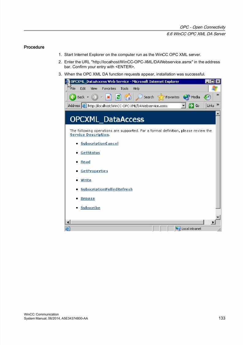
8/20/2019 WinCC Communication en-US en-US
http://slidepdf.com/reader/full/wincc-communication-en-us-en-us 133/527
Procedure
1. Start Internet Explorer on the computer run as the WinCC OPC XML server.
2. Enter the URL "http://localhost/WinCC-OPC-XML/DAWebservice.asmx" in the addressbar. Confirm your entry with <ENTER>.
3. When the OPC XML DA function requests appear, installation was successful.
OPC - Open Connectivity
6.6 WinCC OPC XML DA Server
WinCC: CommunicationSystem Manual, 06/2014, A5E34374800-AA 133
8/20/2019 WinCC Communication en-US en-US
http://slidepdf.com/reader/full/wincc-communication-en-us-en-us 134/527
6.7 WinCC OPC DA server
6.7.1 Functionality of the WinCC OPC DA Server
Introduction
The WinCC OPC DA Server supports OPC Data Access specifications 2.05a and 3.00. Thishas been confirmed by the compliance test.
The WinCC OPC DA server is a DCOM application. This interface is used by the WinCC OPCDA server to make the required information about WinCC tag available to the WinCC client.
The WinCC OPC DA server is active, if the WinCC OPC DA client is accessing it via a
connection. To establish successful OPC communication, the following must be observed:● The WinCC project of the WinCC OPC DA server must be enabled.
● The computer on which the WinCC OPC DA server runs must be accessible via its IPaddress.
Installation
The WinCC OPC DA server can be selected during the installation of WinCC. After installation,the WinCC OPC DA server is immediately usable without any further configuration.
The WinCC OPC DA server can be implemented on a WinCC server or a WinCC client.
Configuration tip
In your WinCC project you can summarize for structuring purposes tags in tag groups. Thetags should not have the same name as the group.
Note
If the Internet options on a computer are set to automatically detect settings under"Connections -> LAN Settings", access to OPC DA via the web service will take significantlylonger.
See also
Querying the OPC DA Server Name (Page 136)
Using Multiple OPC DA Servers (Page 135)
Example of WinCC to WinCC Connection (Page 137)
Example of WinCC - SIMATIC NET FMS OPC Server Connection (Page 141)
Example of a WinCC - SIMATIC NET S7 OPC Server Connection (Page 143)
Example of the WinCC - Microsoft Excel Connection (Page 149)
OPC - Open Connectivity
6.7 WinCC OPC DA server
WinCC: Communication134 System Manual, 06/2014, A5E34374800-AA
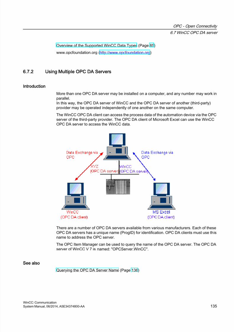
8/20/2019 WinCC Communication en-US en-US
http://slidepdf.com/reader/full/wincc-communication-en-us-en-us 135/527
Overview of the Supported WinCC Data Types (Page 85)
www.opcfoundation.org (http://www.opcfoundation.org)
6.7.2 Using Multiple OPC DA Servers
Introduction
More than one OPC DA server may be installed on a computer, and any number may work inparallel.In this way, the OPC DA server of WinCC and the OPC DA server of another (third-party)provider may be operated independently of one another on the same computer.
The WinCC OPC DA client can access the process data of the automation device via the OPCserver of the third-party provider. The OPC DA client of Microsoft Excel can use the WinCCOPC DA server to access the WinCC data.
There are a number of OPC DA servers available from various manufacturers. Each of these
OPC DA servers has a unique name (ProgID) for identification. OPC DA clients must use thisname to address the OPC server.
The OPC Item Manager can be used to query the name of the OPC DA server. The OPC DAserver of WinCC V 7 is named: "OPCServer.WinCC".
See also
Querying the OPC DA Server Name (Page 136)
OPC - Open Connectivity
6.7 WinCC OPC DA server
WinCC: CommunicationSystem Manual, 06/2014, A5E34374800-AA 135
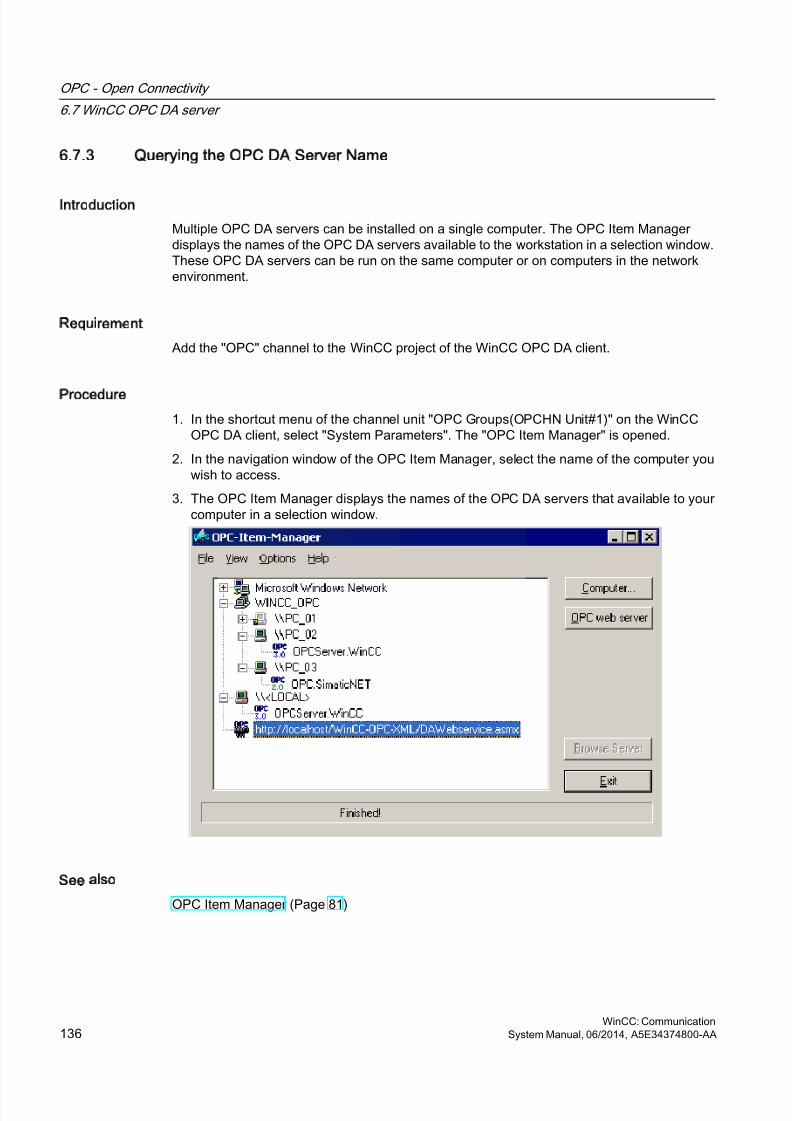
8/20/2019 WinCC Communication en-US en-US
http://slidepdf.com/reader/full/wincc-communication-en-us-en-us 136/527
6.7.3 Querying the OPC DA Server Name
Introduction
Multiple OPC DA servers can be installed on a single computer. The OPC Item Managerdisplays the names of the OPC DA servers available to the workstation in a selection window.These OPC DA servers can be run on the same computer or on computers in the networkenvironment.
Requirement
Add the "OPC" channel to the WinCC project of the WinCC OPC DA client.
Procedure
1. In the shortcut menu of the channel unit "OPC Groups(OPCHN Unit#1)" on the WinCCOPC DA client, select "System Parameters". The "OPC Item Manager" is opened.
2. In the navigation window of the OPC Item Manager, select the name of the computer youwish to access.
3. The OPC Item Manager displays the names of the OPC DA servers that available to yourcomputer in a selection window.
See also
OPC Item Manager (Page 81)
OPC - Open Connectivity
6.7 WinCC OPC DA server
WinCC: Communication136 System Manual, 06/2014, A5E34374800-AA
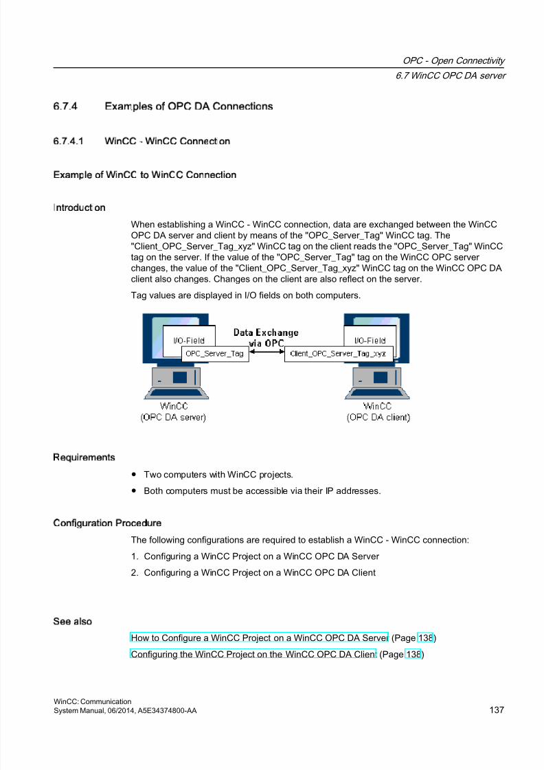
8/20/2019 WinCC Communication en-US en-US
http://slidepdf.com/reader/full/wincc-communication-en-us-en-us 137/527
6.7.4 Examples of OPC DA Connections
6.7.4.1 WinCC - WinCC Connection
Example of WinCC to WinCC Connection
Introduction
When establishing a WinCC - WinCC connection, data are exchanged between the WinCCOPC DA server and client by means of the "OPC_Server_Tag" WinCC tag. The"Client_OPC_Server_Tag_xyz" WinCC tag on the client reads the "OPC_Server_Tag" WinCCtag on the server. If the value of the "OPC_Server_Tag" tag on the WinCC OPC server
changes, the value of the "Client_OPC_Server_Tag_xyz" WinCC tag on the WinCC OPC DAclient also changes. Changes on the client are also reflect on the server.
Tag values are displayed in I/O fields on both computers.
Requirements
● Two computers with WinCC projects.
● Both computers must be accessible via their IP addresses.
Configuration Procedure
The following configurations are required to establish a WinCC - WinCC connection:1. Configuring a WinCC Project on a WinCC OPC DA Server
2. Configuring a WinCC Project on a WinCC OPC DA Client
See also
How to Configure a WinCC Project on a WinCC OPC DA Server (Page 138)
Configuring the WinCC Project on the WinCC OPC DA Client (Page 138)
OPC - Open Connectivity
6.7 WinCC OPC DA server
WinCC: CommunicationSystem Manual, 06/2014, A5E34374800-AA 137
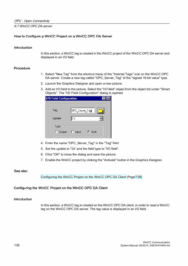
8/20/2019 WinCC Communication en-US en-US
http://slidepdf.com/reader/full/wincc-communication-en-us-en-us 138/527
How to Configure a WinCC Project on a WinCC OPC DA Server
Introduction
In this section, a WinCC tag is created in the WinCC project of the WinCC OPC DA server anddisplayed in an I/O field.
Procedure
1. Select "New Tag" from the shortcut menu of the "Internal Tags" icon on the WinCC OPCDA server. Create a new tag called "OPC_Server_Tag" of the "signed 16-bit value" type.
2. Launch the Graphics Designer and open a new picture.
3. Add an I/O field to the picture. Select the "I/O field" object from the object list under "Smart
Objects". The "I/O Field Configuration" dialog is opened.
4. Enter the name "OPC_Server_Tag" in the "Tag" field.
5. Set the update to "2s" and the field type to "I/O field".
6. Click "OK" to close the dialog and save the picture.
7. Enable the WinCC project by clicking the "Activate" button in the Graphics Designer.
See also
Configuring the WinCC Project on the WinCC OPC DA Client (Page 138)
Configuring the WinCC Project on the WinCC OPC DA Client
Introduction
In this section, a WinCC tag is created on the WinCC OPC DA client, in order to read a WinCCtag on the WinCC OPC DA server. The tag value is displayed in an I/O field.
OPC - Open Connectivity
6.7 WinCC OPC DA server
WinCC: Communication138 System Manual, 06/2014, A5E34374800-AA
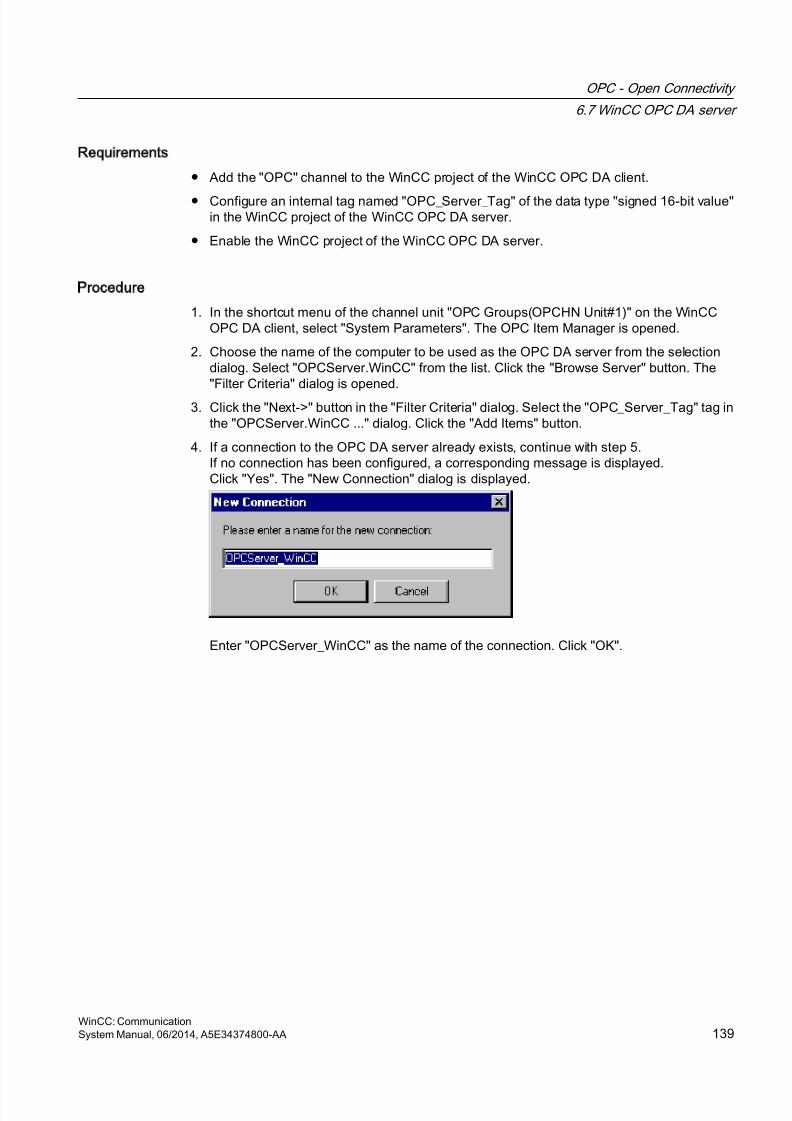
8/20/2019 WinCC Communication en-US en-US
http://slidepdf.com/reader/full/wincc-communication-en-us-en-us 139/527
Requirements
● Add the "OPC" channel to the WinCC project of the WinCC OPC DA client.
● Configure an internal tag named "OPC_Server_Tag" of the data type "signed 16-bit value"in the WinCC project of the WinCC OPC DA server.
● Enable the WinCC project of the WinCC OPC DA server.
Procedure
1. In the shortcut menu of the channel unit "OPC Groups(OPCHN Unit#1)" on the WinCCOPC DA client, select "System Parameters". The OPC Item Manager is opened.
2. Choose the name of the computer to be used as the OPC DA server from the selectiondialog. Select "OPCServer.WinCC" from the list. Click the "Browse Server" button. The"Filter Criteria" dialog is opened.
3. Click the "Next->" button in the "Filter Criteria" dialog. Select the "OPC_Server_Tag" tag inthe "OPCServer.WinCC ..." dialog. Click the "Add Items" button.
4. If a connection to the OPC DA server already exists, continue with step 5.If no connection has been configured, a corresponding message is displayed.Click "Yes". The "New Connection" dialog is displayed.
Enter "OPCServer_WinCC" as the name of the connection. Click "OK".
OPC - Open Connectivity
6.7 WinCC OPC DA server
WinCC: CommunicationSystem Manual, 06/2014, A5E34374800-AA 139
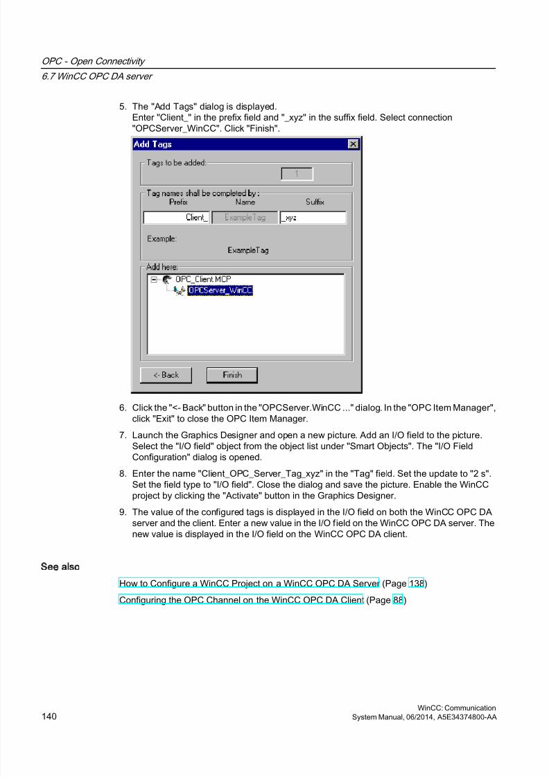
8/20/2019 WinCC Communication en-US en-US
http://slidepdf.com/reader/full/wincc-communication-en-us-en-us 140/527
5. The "Add Tags" dialog is displayed.Enter "Client_" in the prefix field and "_xyz" in the suffix field. Select connection"OPCServer_WinCC". Click "Finish".
6. Click the "<- Back" button in the "OPCServer.WinCC ..." dialog. In the "OPC Item Manager",click "Exit" to close the OPC Item Manager.
7. Launch the Graphics Designer and open a new picture. Add an I/O field to the picture.Select the "I/O field" object from the object list under "Smart Objects". The "I/O FieldConfiguration" dialog is opened.
8. Enter the name "Client_OPC_Server_Tag_xyz" in the "Tag" field. Set the update to "2 s".Set the field type to "I/O field". Close the dialog and save the picture. Enable the WinCCproject by clicking the "Activate" button in the Graphics Designer.
9. The value of the configured tags is displayed in the I/O field on both the WinCC OPC DAserver and the client. Enter a new value in the I/O field on the WinCC OPC DA server. Thenew value is displayed in the I/O field on the WinCC OPC DA client.
See also
How to Configure a WinCC Project on a WinCC OPC DA Server (Page 138)
Configuring the OPC Channel on the WinCC OPC DA Client (Page 88)
OPC - Open Connectivity
6.7 WinCC OPC DA server
WinCC: Communication140 System Manual, 06/2014, A5E34374800-AA
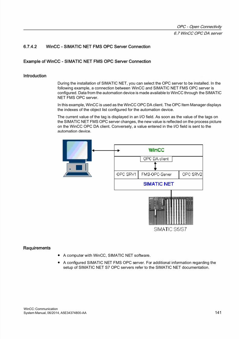
8/20/2019 WinCC Communication en-US en-US
http://slidepdf.com/reader/full/wincc-communication-en-us-en-us 141/527
6.7.4.2 WinCC - SIMATIC NET FMS OPC Server Connection
Example of WinCC - SIMATIC NET FMS OPC Server Connection
Introduction
During the installation of SIMATIC NET, you can select the OPC server to be installed. In thefollowing example, a connection between WinCC and SIMATIC NET FMS OPC server isconfigured. Data from the automation device is made available to WinCC through the SIMATICNET FMS OPC server.
In this example, WinCC is used as the WinCC OPC DA client. The OPC Item Manager displaysthe indexes of the object list configured for the automation device.
The current value of the tag is displayed in an I/O field. As soon as the value of the tags onthe SIMATIC NET FMS OPC server changes, the new value is reflected on the process pictureon the WinCC OPC DA client. Conversely, a value entered in the I/O field is sent to theautomation device.
Requirements
● A computer with WinCC, SIMATIC NET software.
● A configured SIMATIC NET FMS OPC server. For additional information regarding thesetup of SIMATIC NET S7 OPC servers refer to the SIMATIC NET documentation.
OPC - Open Connectivity
6.7 WinCC OPC DA server
WinCC: CommunicationSystem Manual, 06/2014, A5E34374800-AA 141
8/20/2019 WinCC Communication en-US en-US
http://slidepdf.com/reader/full/wincc-communication-en-us-en-us 142/527
Configuration steps
The following configuration is required in the WinCC project of the WinCC OPC DA client:
1. Configuring a WinCC - SIMATIC NET FMS OPC server connection
Communication Manual
The communication manual contains additional information and extensive examples for thechannel configuration. This manual is available for download on the Internet:
● http://support.automation.siemens.com/
Search by item number:
● A5E00391327
How to Configure the WinCC - SIMATIC NET FMS OPC Server Connection
Introduction
In this section, a WinCC tag that accesses an FMS index is configured in the WinCC projectof the WinCC OPC DA client. The tag value is displayed in an I/O field.
Requirement
● Add the "OPC" channel to the WinCC project of the WinCC OPC DA client.
Procedure
1. In the shortcut menu of the channel unit "OPC Groups(OPCHN Unit#1)" on the WinCCOPC DA client, select "System Parameters". The OPC Item Manager is opened.
2. Choose the name of the computer to be used as the OPC DA server from the selectiondialog. Select "OPC.SIMATICNet" from the list.Click the "Browse Server" button. The "Filter Criteria" dialog is opened.
3. Click the "Next->" button in the "Filter Criteria" dialog. The "OPC.SIMATICNet.." dialog isopened. All FMS indexes configured are displayed in a selection list. Select an index. Click
the "Add Items" button.
OPC - Open Connectivity
6.7 WinCC OPC DA server
WinCC: Communication142 System Manual, 06/2014, A5E34374800-AA

8/20/2019 WinCC Communication en-US en-US
http://slidepdf.com/reader/full/wincc-communication-en-us-en-us 143/527
4. If a connection to the SIMATIC NET FMS OPC server already exists, continue with step 5.If no connection has been configured, a corresponding message is displayed.Click "Yes". The "New Connection" dialog is displayed.
Enter "OPC_SIimaticNET" as the name of the connection. Click "OK".
5. The "Add Tags" dialog is opened.
Enter "Client_" in the prefix field and "_xyz" in the suffix field. Select the connection"OPC_SimaticNET". Click "Finish".
6. Click the "<- Back" button in the "OPC.SIMATICNet .." dialog. In the "OPC Item Manager",click "Exit" to close the OPC Item Manager.
7. Launch the Graphics Designer and open a new picture. Add an I/O field to the picture.Select the "I/O field" object from the object list under "Smart Objects". The "I/O FieldConfiguration" dialog is opened.
8. Enter the name of the tags in the "Tag" field. Set the update to "2s". Set the field type to "I/O field".
9. Click "OK" to close the dialog and save the picture. Enable the WinCC project by clicking
the "Activate" button in the Graphics Designer.10.The current value of the FMS index is shown in the I/O field. The value is updated every
two seconds. Enter a value in the I/O field. The changed value is passed to the automationdevice.
See also
Configuring the OPC Channel on the WinCC OPC DA Client (Page 88)
6.7.4.3 WinCC - SIMATIC NET S7-OPC Server Connection
Example of a WinCC - SIMATIC NET S7 OPC Server Connection
During the installation of SIMATIC NET, you can select the OPC server to be installed. In thefollowing example, a WinCC - SIMATIC NET S7 OPC server is configured. Data from theautomation device is made available to the WinCC client via the SIMATIC NET S7 OPC server.
The current value of the tag is displayed in an I/O field on the WinCC OPC client. As soon asthe value of the tags on the SIMATIC NET S7 OPC server changes, the changed value isshown on the process picture. Conversely, a value entered in the I/O field is sent to theautomation device.
OPC - Open Connectivity
6.7 WinCC OPC DA server
WinCC: CommunicationSystem Manual, 06/2014, A5E34374800-AA 143
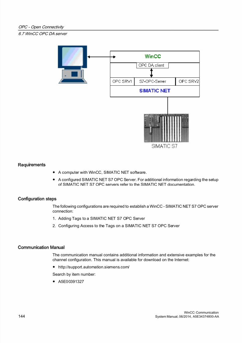
8/20/2019 WinCC Communication en-US en-US
http://slidepdf.com/reader/full/wincc-communication-en-us-en-us 144/527
Requirements
● A computer with WinCC, SIMATIC NET software.
● A configured SIMATIC NET S7 OPC Server. For additional information regarding the setupof SIMATIC NET S7 OPC servers refer to the SIMATIC NET documentation.
Configuration steps
The following configurations are required to establish a WinCC - SIMATIC NET S7 OPC serverconnection:
1. Adding Tags to a SIMATIC NET S7 OPC Server
2. Configuring Access to the Tags on a SIMATIC NET S7 OPC Server
Communication Manual
The communication manual contains additional information and extensive examples for thechannel configuration. This manual is available for download on the Internet:
● http://support.automation.siemens.com/
Search by item number:
● A5E00391327
OPC - Open Connectivity
6.7 WinCC OPC DA server
WinCC: Communication144 System Manual, 06/2014, A5E34374800-AA
8/20/2019 WinCC Communication en-US en-US
http://slidepdf.com/reader/full/wincc-communication-en-us-en-us 145/527
Adding Tags to the SIMATIC NET S7 OPC Server
Introduction
In order for the OPC Item Manager to display the tags, they must be added to the addressspace of the SIMATIC NET S7 OPC server. The "OPC Scout" program is used for theconfiguration. OPC Scout is set up by the SIMATIC NET installer. For this example, the markerword "0" in the automation device is addressed.
Table of Parameters Used
Parameter Value
Data type W
Range byte 0
No. values 1
Item alias MW0
OPC - Open Connectivity
6.7 WinCC OPC DA server
WinCC: CommunicationSystem Manual, 06/2014, A5E34374800-AA 145
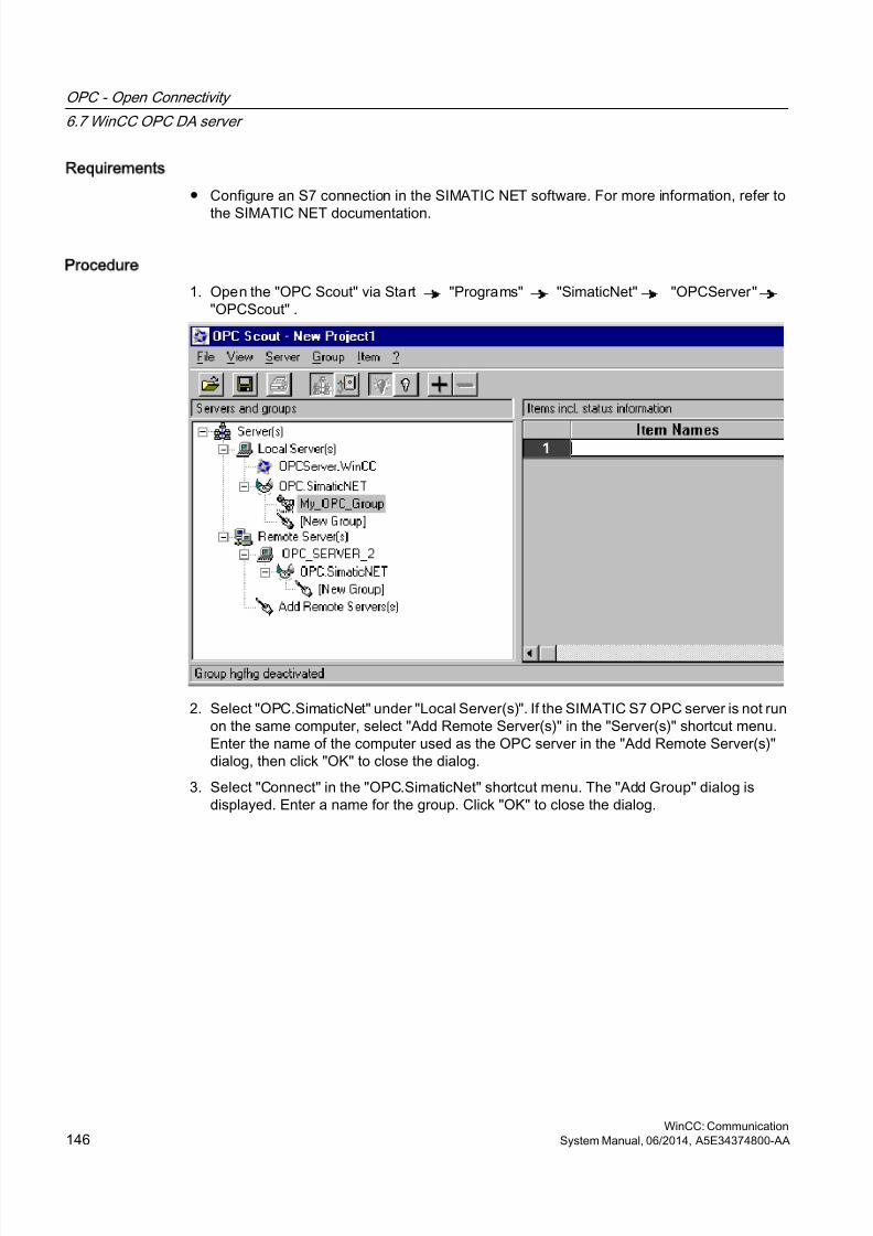
8/20/2019 WinCC Communication en-US en-US
http://slidepdf.com/reader/full/wincc-communication-en-us-en-us 146/527
Requirements
● Configure an S7 connection in the SIMATIC NET software. For more information, refer to
the SIMATIC NET documentation.
Procedure
1. Open the "OPC Scout" via Start "Programs" "SimaticNet" "OPCServer""OPCScout" .
2. Select "OPC.SimaticNet" under "Local Server(s)". If the SIMATIC S7 OPC server is not runon the same computer, select "Add Remote Server(s)" in the "Server(s)" shortcut menu.Enter the name of the computer used as the OPC server in the "Add Remote Server(s)"dialog, then click "OK" to close the dialog.
3. Select "Connect" in the "OPC.SimaticNet" shortcut menu. The "Add Group" dialog isdisplayed. Enter a name for the group. Click "OK" to close the dialog.
OPC - Open Connectivity
6.7 WinCC OPC DA server
WinCC: Communication146 System Manual, 06/2014, A5E34374800-AA
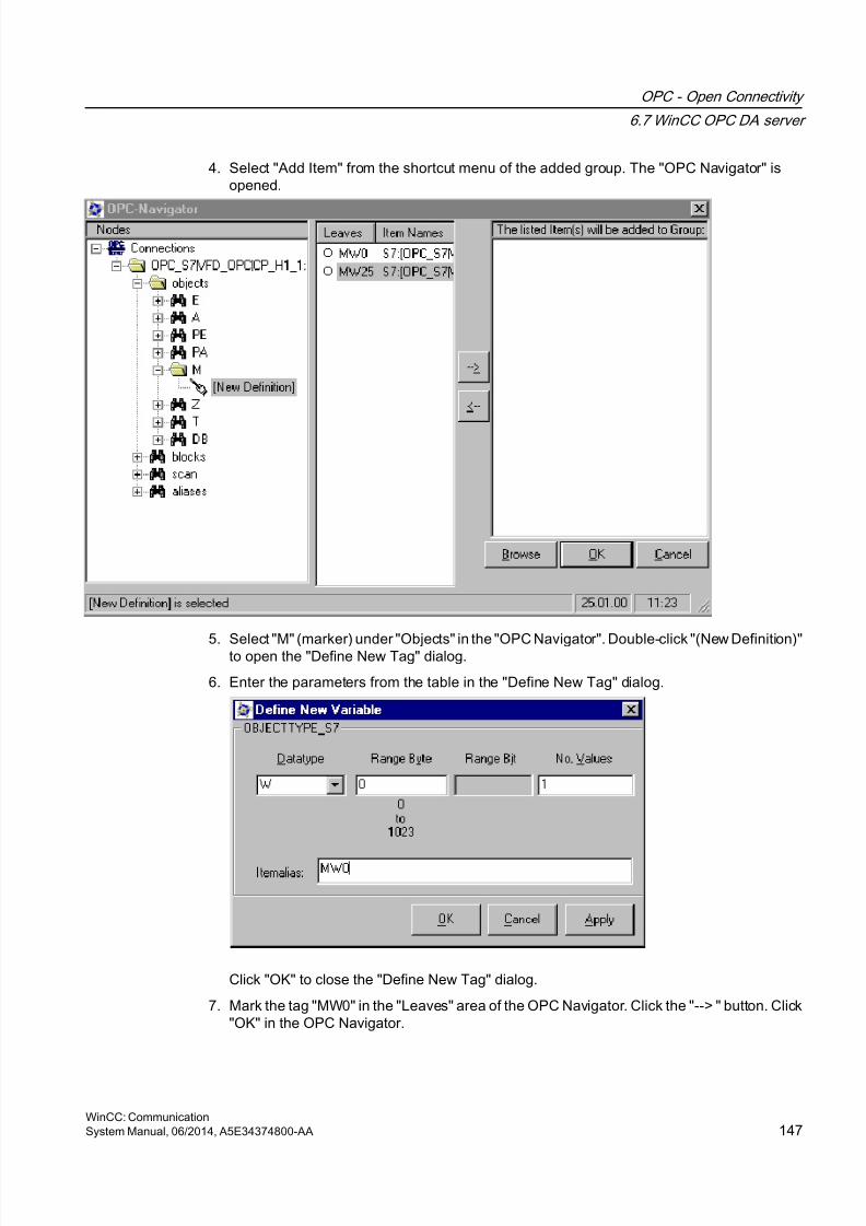
8/20/2019 WinCC Communication en-US en-US
http://slidepdf.com/reader/full/wincc-communication-en-us-en-us 147/527
4. Select "Add Item" from the shortcut menu of the added group. The "OPC Navigator" isopened.
5. Select "M" (marker) under "Objects" in the "OPC Navigator". Double-click "(New Definition)"to open the "Define New Tag" dialog.
6. Enter the parameters from the table in the "Define New Tag" dialog.
Click "OK" to close the "Define New Tag" dialog.
7. Mark the tag "MW0" in the "Leaves" area of the OPC Navigator. Click the "--> " button. Click"OK" in the OPC Navigator.
OPC - Open Connectivity
6.7 WinCC OPC DA server
WinCC: CommunicationSystem Manual, 06/2014, A5E34374800-AA 147
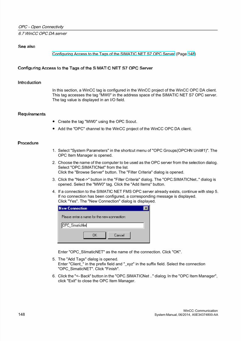
8/20/2019 WinCC Communication en-US en-US
http://slidepdf.com/reader/full/wincc-communication-en-us-en-us 148/527
See also
Configuring Access to the Tags of the SIMATIC NET S7 OPC Server (Page 148)
Configuring Access to the Tags of the SIMATIC NET S7 OPC Server
Introduction
In this section, a WinCC tag is configured in the WinCC project of the WinCC OPC DA client.This tag accesses the tag "MW0" in the address space of the SIMATIC NET S7 OPC server.The tag value is displayed in an I/O field.
Requirements
● Create the tag "MW0" using the OPC Scout.
● Add the "OPC" channel to the WinCC project of the WinCC OPC DA client.
Procedure
1. Select "System Parameters" in the shortcut menu of "OPC Groups(OPCHN Unit#1)". TheOPC Item Manager is opened.
2. Choose the name of the computer to be used as the OPC server from the selection dialog.Select "OPC.SIMATICNet" from the list.Click the "Browse Server" button. The "Filter Criteria" dialog is opened.
3. Click the "Next->" button in the "Filter Criteria" dialog. The "OPC.SIMATICNet.." dialog isopened. Select the "MW0" tag. Click the "Add Items" button.
4. If a connection to the SIMATIC NET FMS OPC server already exists, continue with step 5.If no connection has been configured, a corresponding message is displayed.Click "Yes". The "New Connection" dialog is displayed.
Enter "OPC_SIimaticNET" as the name of the connection. Click "OK".
5. The "Add Tags" dialog is opened.Enter "Client_" in the prefix field and "_xyz" in the suffix field. Select the connection"OPC_SimaticNET". Click "Finish".
6. Click the "<- Back" button in the "OPC.SIMATICNet .." dialog. In the "OPC Item Manager",click "Exit" to close the OPC Item Manager.
OPC - Open Connectivity
6.7 WinCC OPC DA server
WinCC: Communication148 System Manual, 06/2014, A5E34374800-AA
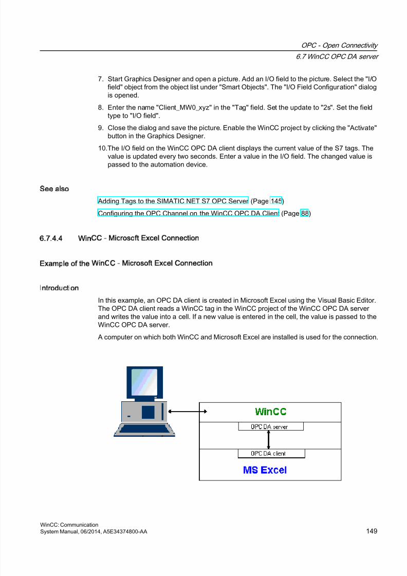
8/20/2019 WinCC Communication en-US en-US
http://slidepdf.com/reader/full/wincc-communication-en-us-en-us 149/527
7. Start Graphics Designer and open a picture. Add an I/O field to the picture. Select the "I/Ofield" object from the object list under "Smart Objects". The "I/O Field Configuration" dialogis opened.
8. Enter the name "Client_MW0_xyz" in the "Tag" field. Set the update to "2s". Set the fieldtype to "I/O field".
9. Close the dialog and save the picture. Enable the WinCC project by clicking the "Activate"button in the Graphics Designer.
10.The I/O field on the WinCC OPC DA client displays the current value of the S7 tags. Thevalue is updated every two seconds. Enter a value in the I/O field. The changed value ispassed to the automation device.
See also
Adding Tags to the SIMATIC NET S7 OPC Server (Page 145)Configuring the OPC Channel on the WinCC OPC DA Client (Page 88)
6.7.4.4 WinCC - Microsoft Excel Connection
Example of the WinCC - Microsoft Excel Connection
Introduction
In this example, an OPC DA client is created in Microsoft Excel using the Visual Basic Editor.The OPC DA client reads a WinCC tag in the WinCC project of the WinCC OPC DA serverand writes the value into a cell. If a new value is entered in the cell, the value is passed to theWinCC OPC DA server.
A computer on which both WinCC and Microsoft Excel are installed is used for the connection.
OPC - Open Connectivity
6.7 WinCC OPC DA server
WinCC: CommunicationSystem Manual, 06/2014, A5E34374800-AA 149
8/20/2019 WinCC Communication en-US en-US
http://slidepdf.com/reader/full/wincc-communication-en-us-en-us 150/527
Configuration steps
The following configurations must be made in Microsoft Excel:
1. Creating an OPC DA client in Visual Basic Editor of Microsoft Excel
2. Configuring access to a WinCC tag in Microsoft Excel
See also
How to Configure the Access to a WinCC Tag in Microsoft Excel (Page 152)
Creating an OPC DA Client in Microsoft Excel (Page 150)
Creating an OPC DA Client in Microsoft Excel
Introduction
To use Microsoft Excel as an OPC DA client, a special script must be created in the VisualBasic Editor of Microsoft Excel.
Requirements
Basic knowledge of Visual Basic Editor in Microsoft Excel.
Procedure
1. Open Microsoft Excel with a new workbook.
2. In the "Tools" menu of the Visual Basic Editor, click "Macro". The Visual Basic Editorfor Microsoft Excel is opened.
3. In the "Tools" menu of the Visual Basic Editor, select "References...". The "References -VBAProject" dialog is displayed. Locate entry "Siemens OPC DAAutomation 2.0" in the listof available references. Select the corresponding check box. Click "OK".
4. Copy the script shown below. This script is only available in the online help.
5. Open a new code window by double-clicking "Sheet1" in the project window of the Visual
Basic Editor.6. Paste the script into the code window.
7. Select "Save" from the "File" menu. Select "Close and Return to Microsoft Excel" from the"File" menu.
Example Script
Option Explicit
Option Base 1
OPC - Open Connectivity
6.7 WinCC OPC DA server
WinCC: Communication150 System Manual, 06/2014, A5E34374800-AA
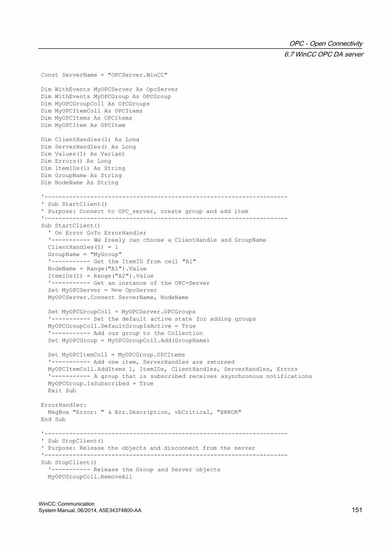
8/20/2019 WinCC Communication en-US en-US
http://slidepdf.com/reader/full/wincc-communication-en-us-en-us 151/527
Const ServerName = "OPCServer.WinCC"
Dim WithEvents MyOPCServer As OpcServer
Dim WithEvents MyOPCGroup As OPCGroupDim MyOPCGroupColl As OPCGroups
Dim MyOPCItemColl As OPCItems
Dim MyOPCItems As OPCItems
Dim MyOPCItem As OPCItem
Dim ClientHandles(1) As Long
Dim ServerHandles() As Long
Dim Values(1) As Variant
Dim Errors() As Long
Dim ItemIDs(1) As String
Dim GroupName As String
Dim NodeName As String
'---------------------------------------------------------------------
' Sub StartClient()
' Purpose: Connect to OPC_server, create group and add item
'---------------------------------------------------------------------
Sub StartClient()
' On Error GoTo ErrorHandler
'----------- We freely can choose a ClientHandle and GroupName
ClientHandles(1) = 1
GroupName = "MyGroup"
'----------- Get the ItemID from cell "A1"
NodeName = Range("A1").Value
ItemIDs(1) = Range("A2").Value
'----------- Get an instance of the OPC-Server
Set MyOPCServer = New OpcServer MyOPCServer.Connect ServerName, NodeName
Set MyOPCGroupColl = MyOPCServer.OPCGroups
'----------- Set the default active state for adding groups
MyOPCGroupColl.DefaultGroupIsActive = True
'----------- Add our group to the Collection
Set MyOPCGroup = MyOPCGroupColl.Add(GroupName)
Set MyOPCItemColl = MyOPCGroup.OPCItems
'----------- Add one item, ServerHandles are returned
MyOPCItemColl.AddItems 1, ItemIDs, ClientHandles, ServerHandles, Errors
'----------- A group that is subscribed receives asynchronous notifications
MyOPCGroup.IsSubscribed = True
Exit Sub
ErrorHandler:
MsgBox "Error: " & Err.Description, vbCritical, "ERROR"
End Sub
'---------------------------------------------------------------------
' Sub StopClient()
' Purpose: Release the objects and disconnect from the server
'---------------------------------------------------------------------
Sub StopClient()
'----------- Release the Group and Server objects
MyOPCGroupColl.RemoveAll
OPC - Open Connectivity
6.7 WinCC OPC DA server
WinCC: CommunicationSystem Manual, 06/2014, A5E34374800-AA 151
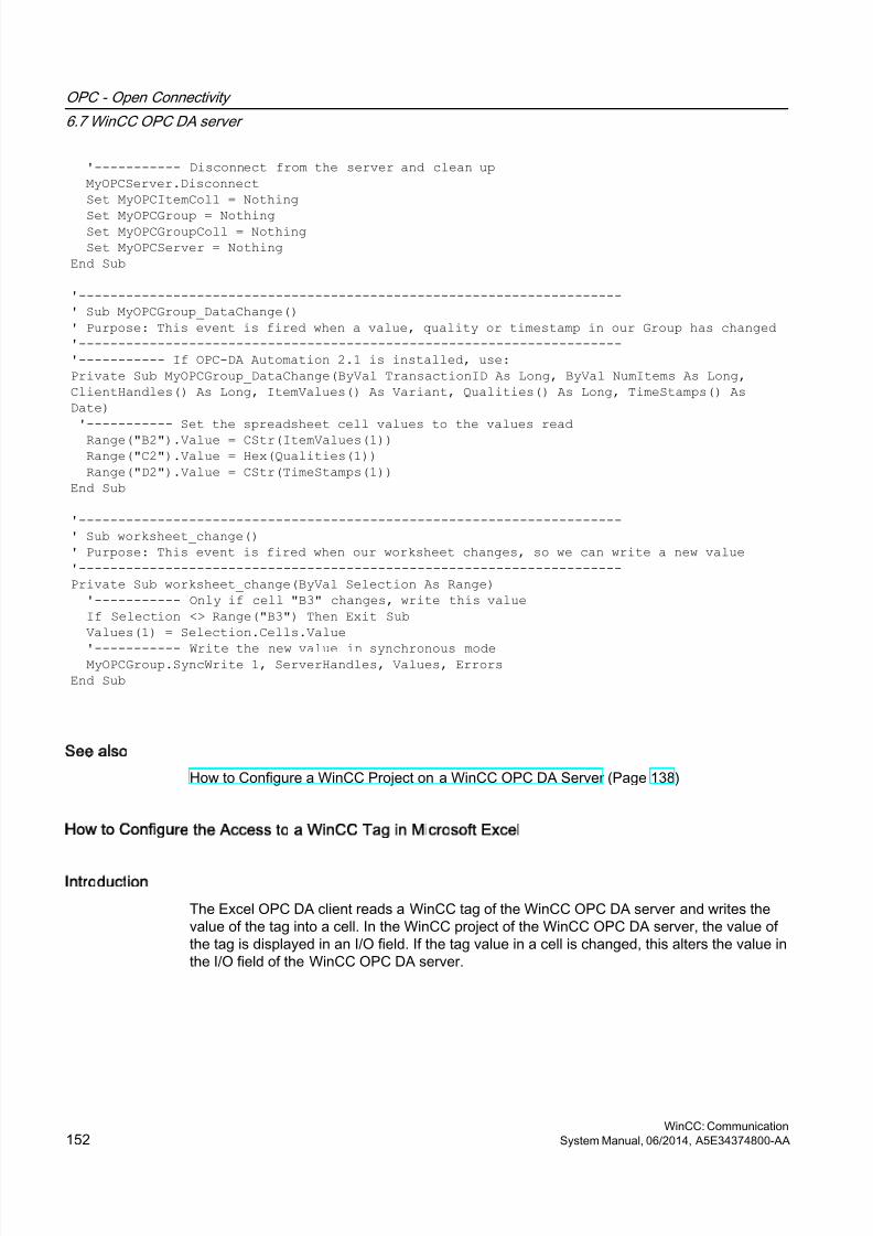
8/20/2019 WinCC Communication en-US en-US
http://slidepdf.com/reader/full/wincc-communication-en-us-en-us 152/527
'----------- Disconnect from the server and clean up
MyOPCServer.Disconnect
Set MyOPCItemColl = Nothing
Set MyOPCGroup = Nothing Set MyOPCGroupColl = Nothing
Set MyOPCServer = Nothing
End Sub
'---------------------------------------------------------------------
' Sub MyOPCGroup_DataChange()
' Purpose: This event is fired when a value, quality or timestamp in our Group has changed
'---------------------------------------------------------------------
'----------- If OPC-DA Automation 2.1 is installed, use:
Private Sub MyOPCGroup_DataChange(ByVal TransactionID As Long, ByVal NumItems As Long,
ClientHandles() As Long, ItemValues() As Variant, Qualities() As Long, TimeStamps() As
Date)
'----------- Set the spreadsheet cell values to the values read
Range("B2").Value = CStr(ItemValues(1))
Range("C2").Value = Hex(Qualities(1))
Range("D2").Value = CStr(TimeStamps(1))
End Sub
'---------------------------------------------------------------------
' Sub worksheet_change()
' Purpose: This event is fired when our worksheet changes, so we can write a new value
'---------------------------------------------------------------------
Private Sub worksheet_change(ByVal Selection As Range)
'----------- Only if cell "B3" changes, write this value
If Selection <> Range("B3") Then Exit Sub
Values(1) = Selection.Cells.Value
'----------- Write the new value in synchronous mode MyOPCGroup.SyncWrite 1, ServerHandles, Values, Errors
End Sub
See also
How to Configure a WinCC Project on a WinCC OPC DA Server (Page 138)
How to Configure the Access to a WinCC Tag in Microsoft Excel
Introduction
The Excel OPC DA client reads a WinCC tag of the WinCC OPC DA server and writes thevalue of the tag into a cell. In the WinCC project of the WinCC OPC DA server, the value ofthe tag is displayed in an I/O field. If the tag value in a cell is changed, this alters the value inthe I/O field of the WinCC OPC DA server.
OPC - Open Connectivity
6.7 WinCC OPC DA server
WinCC: Communication152 System Manual, 06/2014, A5E34374800-AA
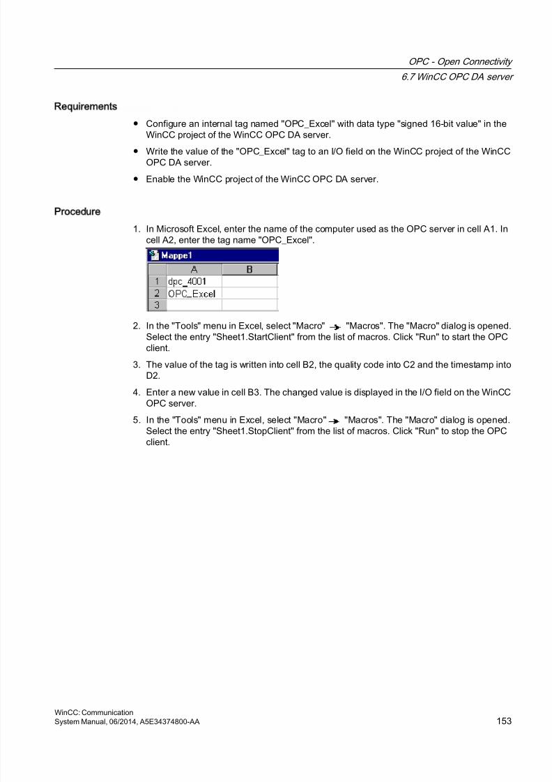
8/20/2019 WinCC Communication en-US en-US
http://slidepdf.com/reader/full/wincc-communication-en-us-en-us 153/527
Requirements
● Configure an internal tag named "OPC_Excel" with data type "signed 16-bit value" in the
WinCC project of the WinCC OPC DA server.● Write the value of the "OPC_Excel" tag to an I/O field on the WinCC project of the WinCC
OPC DA server.
● Enable the WinCC project of the WinCC OPC DA server.
Procedure
1. In Microsoft Excel, enter the name of the computer used as the OPC server in cell A1. Incell A2, enter the tag name "OPC_Excel".
2. In the "Tools" menu in Excel, select "Macro" "Macros". The "Macro" dialog is opened.Select the entry "Sheet1.StartClient" from the list of macros. Click "Run" to start the OPCclient.
3. The value of the tag is written into cell B2, the quality code into C2 and the timestamp intoD2.
4. Enter a new value in cell B3. The changed value is displayed in the I/O field on the WinCCOPC server.
5. In the "Tools" menu in Excel, select "Macro" "Macros". The "Macro" dialog is opened.Select the entry "Sheet1.StopClient" from the list of macros. Click "Run" to stop the OPCclient.
OPC - Open Connectivity
6.7 WinCC OPC DA server
WinCC: CommunicationSystem Manual, 06/2014, A5E34374800-AA 153
8/20/2019 WinCC Communication en-US en-US
http://slidepdf.com/reader/full/wincc-communication-en-us-en-us 154/527
6.8 WinCC OPC HDA server
6.8.1 Functionality of the WinCC OPC HDA server
Introduction
The WinCC OPC HDA server is a DCOM application makings data needed from the archivesystem available to the OPC HDA client. Access the data using Item Handles. Read or writeaccess is enabled. The data can also be analyzed.
The WinCC OPC HDA server supports the OPC Historical Data Access 1.20 specification.This has been confirmed by the compliance test.
The following chapter explains the design of the data structure, as well as the attributes,aggregates and functions supported by the WinCC OPC HDA server. This is not a detaileddescription, but rather a summary of the most important information. For more information,refer to the "OPC Historical Data Access 1.20" specification.
Installation
The WinCC OPC HDA server can be selected during the installation of WinCC. It is possibleto select whether access is made to the WinCC archive system with or without write function .After installation, the WinCC OPC DA server is immediately available for use without anyadditional configuration.
In the case of installation without write access, the data in the WinCC archive system can onlybe read and analyzed. In the case of write access, data in the WinCC archive system can beanalyzed, added, deleted and updated.
The WinCC OPC HDA server can be implemented on a WinCC server or a WinCC client.
Licensing
In order to operate the WinCC OPC HDA server, the following licenses must be installed oneach WinCC computer implemented as an OPC HDA server:
● A valid RT license for WinCC
● WinCC Option Connectivity Pack
OPC HDA Client
All OPC HDA clients that conform to the OPC Historical Data Access 1.20 specification canaccess the WinCC OPC HDA server. You can also create the OPC HDA client yourself. Bycreating proprietary OPC HDA clients, most user-specific requirements can be met.
Examples of how an OPC HDA client can be used include:
● Analysis and evaluation of archived data
● Statistical process control of archives from different OPC HDA servers
OPC - Open Connectivity
6.8 WinCC OPC HDA server
WinCC: Communication154 System Manual, 06/2014, A5E34374800-AA

8/20/2019 WinCC Communication en-US en-US
http://slidepdf.com/reader/full/wincc-communication-en-us-en-us 155/527
To request for historical values using OPC HDA client, you need to take care of the followingduring configuration:
● Select a query cycle in such a way that the client can receive the requested data beforethe next query is sent. Too short cycles can lead to high time delays while receiving data.
● CPU load of the WinCC server depends on the number of tags per query.
Write access to cyclic archive with configured swapping out
In runtime, the data is modified in the cyclic archives on the WinCC server.
Changes are accepted into the swapped-out archive only when the data is changed almostimmediately after being created.
If the concerned archive segment of the circulation archive has already been swapped out,then the change is not done subsequently in the swapped-out archive. Even the modified datais deleted when you delete the archive segment on the WinCC server.
See also
www.opcfoundation.org (http://www.opcfoundation.org)
Quality codes (Page 160)
Data Structure of a WinCC OPC HDA Server (Page 155)
6.8.2 Data Structure of a WinCC OPC HDA Server
6.8.2.1 Data Structure of a WinCC OPC HDA Server
Introduction
The data on the WinCC OPC HDA server are structured. The available data structures arelisted below. This is not a detailed description, but rather a summary of the most importantinformation. For more information, refer to the "OPC Historical Data Access 1.20" specification.
Data structure
Description
Attributes Provide additional quality characteristics for the raw data. Attributes include datatype, specifications re. archiving, etc. For more information, see the overview ofsupported attributes.
Assemblies Summarize raw data of a specified time interval. Aggregates include averagevalue, minimum, maximum, etc. For more information, see overview of supportedaggregates.
OPC - Open Connectivity
6.8 WinCC OPC HDA server
WinCC: CommunicationSystem Manual, 06/2014, A5E34374800-AA 155
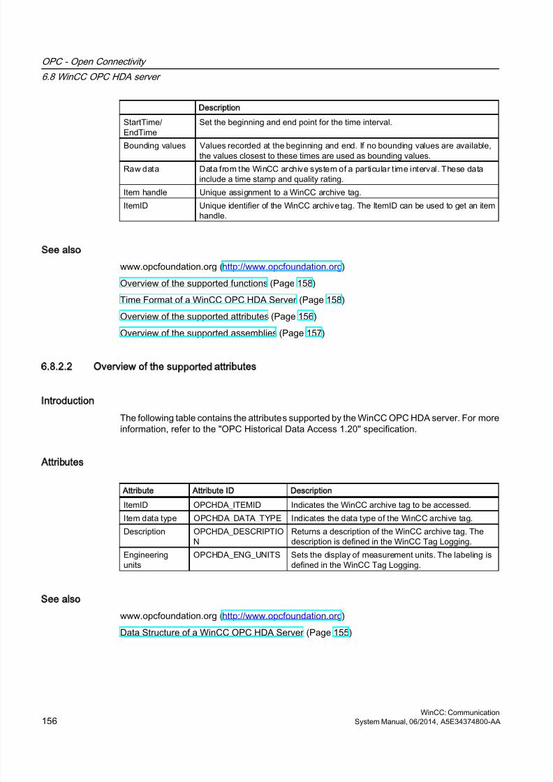
8/20/2019 WinCC Communication en-US en-US
http://slidepdf.com/reader/full/wincc-communication-en-us-en-us 156/527
Description
StartTime/
EndTime
Set the beginning and end point for the time interval.
Bounding values Values recorded at the beginning and end. If no bounding values are available,the values closest to these times are used as bounding values.
Raw data Data from the WinCC archive system of a particular time interval. These datainclude a time stamp and quality rating.
Item handle Unique assignment to a WinCC archive tag.
ItemID Unique identifier of the WinCC archive tag. The ItemID can be used to get an itemhandle.
See also
www.opcfoundation.org (http://www.opcfoundation.org)
Overview of the supported functions (Page 158)
Time Format of a WinCC OPC HDA Server (Page 158)
Overview of the supported attributes (Page 156)
Overview of the supported assemblies (Page 157)
6.8.2.2 Overview of the supported attributes
Introduction
The following table contains the attributes supported by the WinCC OPC HDA server. For moreinformation, refer to the "OPC Historical Data Access 1.20" specification.
Attributes
Attribute Attribute ID Description
ItemID OPCHDA_ITEMID Indicates the WinCC archive tag to be accessed.
Item data type OPCHDA_DATA_TYPE Indicates the data type of the WinCC archive tag.
Description OPCHDA_DESCRIPTION
Returns a description of the WinCC archive tag. Thedescription is defined in the WinCC Tag Logging.
Engineeringunits
OPCHDA_ENG_UNITS Sets the display of measurement units. The labeling isdefined in the WinCC Tag Logging.
See also
www.opcfoundation.org (http://www.opcfoundation.org)
Data Structure of a WinCC OPC HDA Server (Page 155)
OPC - Open Connectivity
6.8 WinCC OPC HDA server
WinCC: Communication156 System Manual, 06/2014, A5E34374800-AA
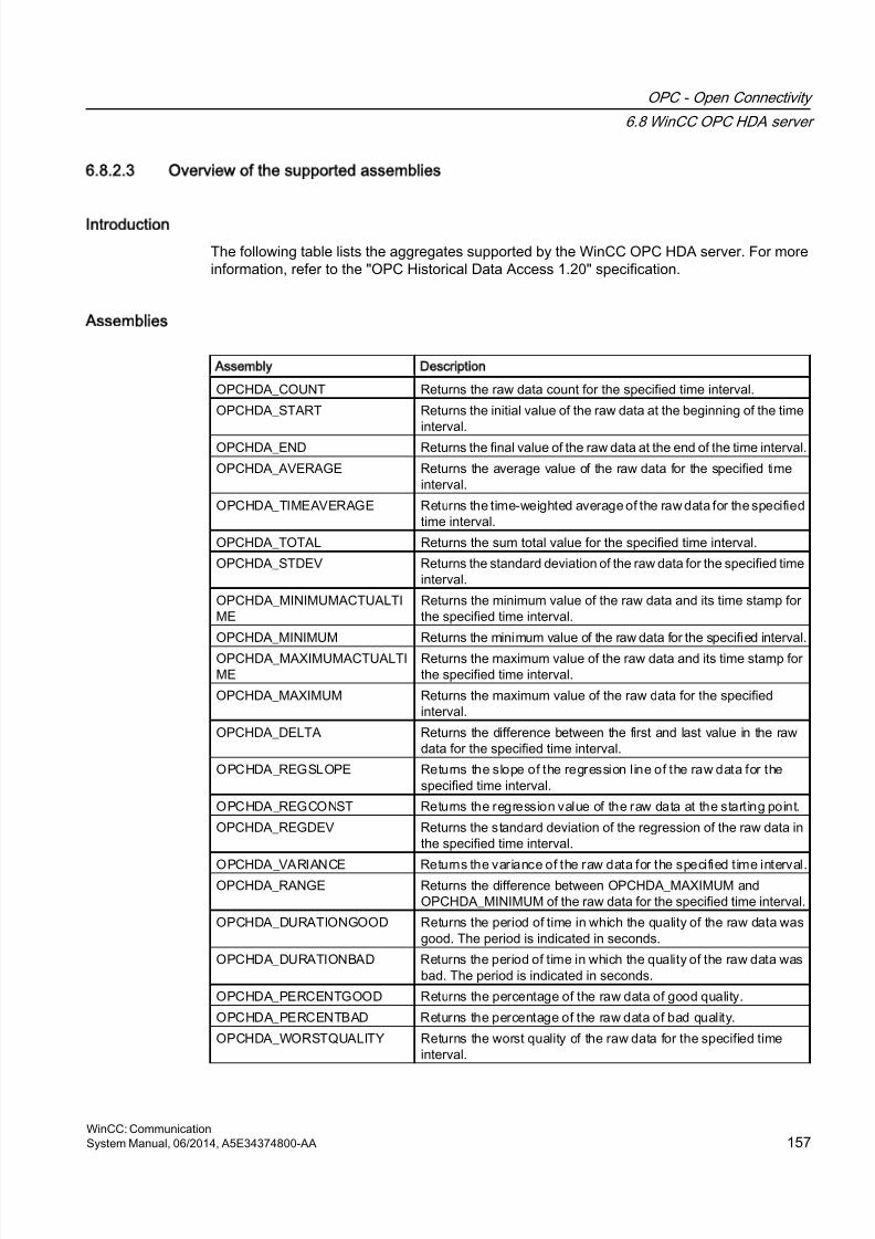
8/20/2019 WinCC Communication en-US en-US
http://slidepdf.com/reader/full/wincc-communication-en-us-en-us 157/527
6.8.2.3 Overview of the supported assemblies
Introduction
The following table lists the aggregates supported by the WinCC OPC HDA server. For moreinformation, refer to the "OPC Historical Data Access 1.20" specification.
Assemblies
Assembly Description
OPCHDA_COUNT Returns the raw data count for the specified time interval.
OPCHDA_START Returns the initial value of the raw data at the beginning of the timeinterval.
OPCHDA_END Returns the final value of the raw data at the end of the time interval.
OPCHDA_AVERAGE Returns the average value of the raw data for the specified timeinterval.
OPCHDA_TIMEAVERAGE Returns the time-weighted average of the raw data for the specifiedtime interval.
OPCHDA_TOTAL Returns the sum total value for the specified time interval.
OPCHDA_STDEV Returns the standard deviation of the raw data for the specified timeinterval.
OPCHDA_MINIMUMACTUALTIME
Returns the minimum value of the raw data and its time stamp forthe specified time interval.
OPCHDA_MINIMUM Returns the minimum value of the raw data for the specified interval.
OPCHDA_MAXIMUMACTUALTIME
Returns the maximum value of the raw data and its time stamp forthe specified time interval.
OPCHDA_MAXIMUM Returns the maximum value of the raw data for the specifiedinterval.
OPCHDA_DELTA Returns the difference between the first and last value in the rawdata for the specified time interval.
OPCHDA_REGSLOPE Returns the slope of the regression line of the raw data for thespecified time interval.
OPCHDA_REGCONST Returns the regression value of the raw data at the starting point.
OPCHDA_REGDEV Returns the standard deviation of the regression of the raw data inthe specified time interval.
OPCHDA_VARIANCE Returns the variance of the raw data for the specified time interval.OPCHDA_RANGE Returns the difference between OPCHDA_MAXIMUM and
OPCHDA_MINIMUM of the raw data for the specified time interval.
OPCHDA_DURATIONGOOD Returns the period of time in which the quality of the raw data wasgood. The period is indicated in seconds.
OPCHDA_DURATIONBAD Returns the period of time in which the quality of the raw data wasbad. The period is indicated in seconds.
OPCHDA_PERCENTGOOD Returns the percentage of the raw data of good quality.
OPCHDA_PERCENTBAD Returns the percentage of the raw data of bad quality.
OPCHDA_WORSTQUALITY Returns the worst quality of the raw data for the specified timeinterval.
OPC - Open Connectivity
6.8 WinCC OPC HDA server
WinCC: CommunicationSystem Manual, 06/2014, A5E34374800-AA 157

8/20/2019 WinCC Communication en-US en-US
http://slidepdf.com/reader/full/wincc-communication-en-us-en-us 158/527
See also
www.opcfoundation.org (http://www.opcfoundation.org)
Data Structure of a WinCC OPC HDA Server (Page 155)
Functionality of the WinCC OPC HDA server (Page 154)
6.8.2.4 Overview of the supported functions
Introduction
The following tables list the functions supported by the WinCC OPC HDA server. Thesefunctions can be used by the OPC HDA client for data exchange. For more information, referto the "OPC Historical Data Access 1.20" specification.
Read
Function Description
ReadRaw Returns the raw data, its quality and time stamp for the specified time interval.
ReadProcessed Returns the calculated value, the quality of the value and the time stamp for thespecified time interval. The calculated value is determined by the selected aggregate.
ReadAtTime Returns the raw data, its quality and time stamp for a particular time interval. If novalue is available, the value for this point is interpolated.
ReadAttribute Returns the item attributes and time stamp for the specified time interval.
See also
www.opcfoundation.org (http://www.opcfoundation.org)
Functionality of the WinCC OPC HDA server (Page 154)
6.8.2.5 Time Format of a WinCC OPC HDA Server
Introduction
The time interval is specified on the WinCC OPC HDA server by setting the starting and endingtimes. The specified time interval determines the observation period for the historical data.When specifying the times, certain formats must be maintained.
The following options are available for the specification of times:
● Absolute based on UTC
● Relative to the local time of the server
OPC - Open Connectivity
6.8 WinCC OPC HDA server
WinCC: Communication158 System Manual, 06/2014, A5E34374800-AA
8/20/2019 WinCC Communication en-US en-US
http://slidepdf.com/reader/full/wincc-communication-en-us-en-us 159/527
Absolute Value According to UTC
By default, the WinCC OPC HDA server uses the coordinated world time (UTC) as its time
base. This time corresponds to the Greenwich Mean Time (Central European Time minus anhour).
Time format
YYYY/MM/DD hh:mm:ss.msmsms
Parameters
YYYY = year
MM = month
DD = day
hh = hoursmm = minutes
ss = seconds
ms = milliseconds
Input example
2002/06/10 09:27:30.000
Specification of Time Relative to Local Time
For this option, the time is entered relative to the local time of the server. The local time zoneis set on the computer's "Date/Time" control panel.
Time format
keyword +/-offset1 +/-offset(n)
The offset is the deviation from the local time of the server.
Keywords
NOW = current local time on the server
SECOND = current second
MINUTE = current minute
HOUR = current hour
DAY = current day
WEEK = current week
MONTH = current month
YEAR = current year
Offset
+/-S = deviation in seconds
+/-M = deviation in minutes
OPC - Open Connectivity
6.8 WinCC OPC HDA server
WinCC: CommunicationSystem Manual, 06/2014, A5E34374800-AA 159
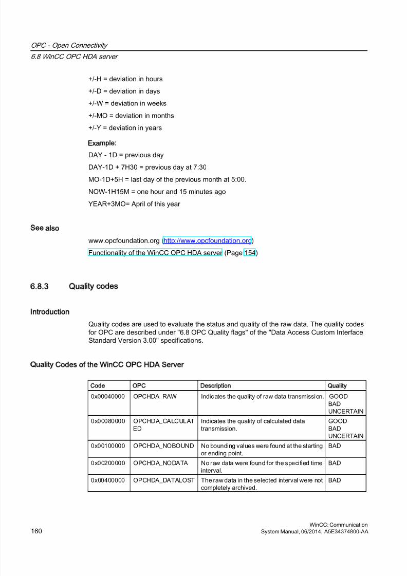
8/20/2019 WinCC Communication en-US en-US
http://slidepdf.com/reader/full/wincc-communication-en-us-en-us 160/527
+/-H = deviation in hours
+/-D = deviation in days
+/-W = deviation in weeks
+/-MO = deviation in months
+/-Y = deviation in years
Example:
DAY - 1D = previous day
DAY-1D + 7H30 = previous day at 7:30
MO-1D+5H = last day of the previous month at 5:00.
NOW-1H15M = one hour and 15 minutes ago
YEAR+3MO= April of this year
See also
www.opcfoundation.org (http://www.opcfoundation.org)
Functionality of the WinCC OPC HDA server (Page 154)
6.8.3 Quality codes
Introduction
Quality codes are used to evaluate the status and quality of the raw data. The quality codesfor OPC are described under "6.8 OPC Quality flags" of the "Data Access Custom InterfaceStandard Version 3.00" specifications.
Quality Codes of the WinCC OPC HDA Server
Code OPC Description Quality
0x00040000 OPCHDA_RAW Indicates the quality of raw data transmission. GOOD
BADUNCERTAIN
0x00080000 OPCHDA_CALCULATED
Indicates the quality of calculated datatransmission.
GOODBADUNCERTAIN
0x00100000 OPCHDA_NOBOUND No bounding values were found at the startingor ending point.
BAD
0x00200000 OPCHDA_NODATA No raw data were found for the specified timeinterval.
BAD
0x00400000 OPCHDA_DATALOST The raw data in the selected interval were notcompletely archived.
BAD
OPC - Open Connectivity
6.8 WinCC OPC HDA server
WinCC: Communication160 System Manual, 06/2014, A5E34374800-AA
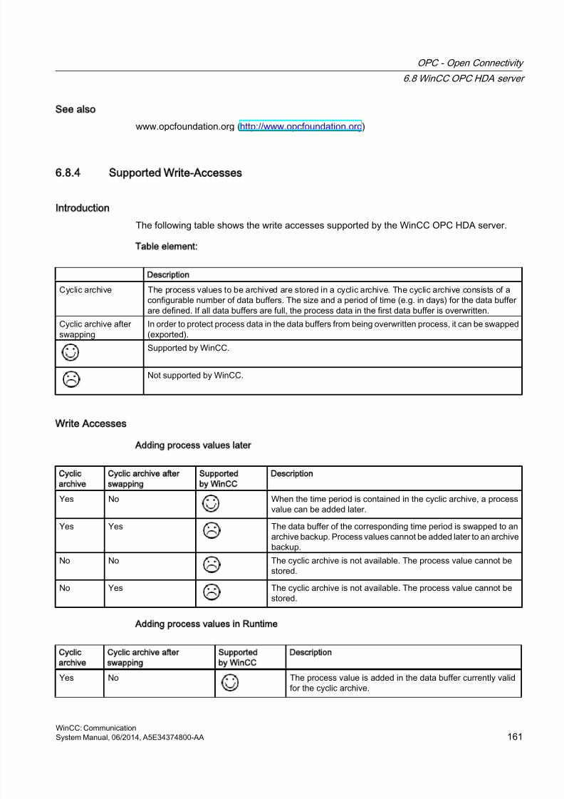
8/20/2019 WinCC Communication en-US en-US
http://slidepdf.com/reader/full/wincc-communication-en-us-en-us 161/527
See also
www.opcfoundation.org (http://www.opcfoundation.org)
6.8.4 Supported Write-Accesses
Introduction
The following table shows the write accesses supported by the WinCC OPC HDA server.
Table element:
Description
Cyclic archive The process values to be archived are stored in a cyclic archive. The cyclic archive consists of aconfigurable number of data buffers. The size and a period of time (e.g. in days) for the data bufferare defined. If all data buffers are full, the process data in the first data buffer is overwritten.
Cyclic archive afterswapping
In order to protect process data in the data buffers from being overwritten process, it can be swapped(exported).
Supported by WinCC.
Not supported by WinCC.
Write Accesses
Adding process values later
Cyclic
archive
Cyclic archive after
swapping
Supported
by WinCC
Description
Yes No When the time period is contained in the cyclic archive, a processvalue can be added later.
Yes Yes The data buffer of the corresponding time period is swapped to anarchive backup. Process values cannot be added later to an archivebackup.
No No The cyclic archive is not available. The process value cannot bestored.
No Yes The cyclic archive is not available. The process value cannot bestored.
Adding process values in Runtime
Cyclic
archive
Cyclic archive after
swapping
Supported
by WinCC
Description
Yes No The process value is added in the data buffer currently validfor the cyclic archive.
OPC - Open Connectivity
6.8 WinCC OPC HDA server
WinCC: CommunicationSystem Manual, 06/2014, A5E34374800-AA 161

8/20/2019 WinCC Communication en-US en-US
http://slidepdf.com/reader/full/wincc-communication-en-us-en-us 162/527
Inserting future process values
Cyclic
archive
Cyclic archive after swapping Supported
by WinCC
Description
YES No During write access, no values can be added in the future.
No No With write access, no values can be added in the future.
Deleting process values
Cyclic
archive
Cyclic archive after
swapping
Supported
by WinCC
Description
Yes No When the time period is contained in the cyclic archive, a processvalue can be deleted.
Yes Yes The data buffer of the corresponding time period is swapped to anarchive backup. Process values can be deleted from an archivebackup.
No No The cyclic archive is not available. The process value cannot bestored.
No Yes The cyclic archive is not available. The process value cannot bestored.
Editing process values
Cyclic
archive
Cyclic archive after
swapping
Supported
by WinCC
Description
Yes No When the time period is contained in the cyclic archive, a processvalue can be edited.
Yes Yes The data buffer of the corresponding time period is swapped to anarchive backup. Process values cannot be edited in an archivebackup.
No No The cyclic archive is not available. The process value cannot bestored.
No Yes The cyclic archive is not available. The process value cannot be
stored.
OPC - Open Connectivity
6.8 WinCC OPC HDA server
WinCC: Communication162 System Manual, 06/2014, A5E34374800-AA
8/20/2019 WinCC Communication en-US en-US
http://slidepdf.com/reader/full/wincc-communication-en-us-en-us 163/527
6.8.5 Example of an OPC HDA Connection
6.8.5.1 Example of an OPC HDA Connection
Introduction
In the example below, a connection between WinCC and the OPC HDA client is configured.Data from the WinCC archive system are made available via the WinCC OPC HDA server.The OPC HDA client accesses the data via item handles. To simplify the configuration process,the OPC HDA browser is used.
The OPC HDA client from the OPC Foundation is used. All OPC HDA clients conforming tothe OPC Historical Data Access 1.20 specification can access the WinCC OPC HDA server.
Requirements
● Create an internal tag named "OPC_HDA" with data type "unsigned 16-bit value" in theWinCC project of the WinCC OPC HDA server.
● Create a process value archive called "HDA_ProcessValueArchive" in the WinCC archivesystem.
● Create an WinCC archive tag called "OPC_HDA_Tag" in the "HDA_ProcessValueArchive"process value archive. Link the WinCC archive tag to the internal tag "OPC_HDA".
● In the Runtime list, launch Tag Logging Runtime and disable Graphics Runtime.
● Launch the WinCC project of the WinCC OPC HDA server.
Configuration steps
The following configurations are required to connect WinCC to the OPC HDA client:
1. Configuring access to a WinCC archive tag using the HDA server browser
2. Reading values from the WinCC archive tags
See also
How to Configure Access to a WinCC Archive Tag Using the HDA Server Browser (Page 165)
HDA server browser (Page 164)
Reading Values of WinCC Archive Tags (Page 166)
OPC - Open Connectivity
6.8 WinCC OPC HDA server
WinCC: CommunicationSystem Manual, 06/2014, A5E34374800-AA 163
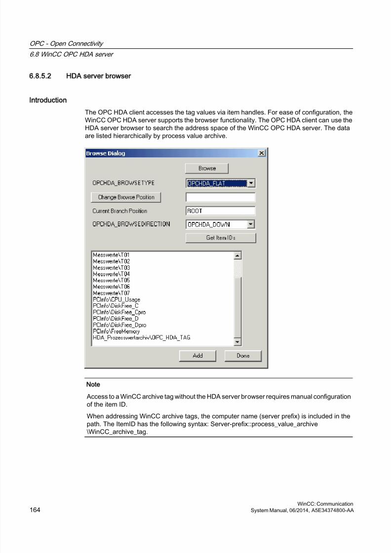
8/20/2019 WinCC Communication en-US en-US
http://slidepdf.com/reader/full/wincc-communication-en-us-en-us 164/527
6.8.5.2 HDA server browser
Introduction
The OPC HDA client accesses the tag values via item handles. For ease of configuration, theWinCC OPC HDA server supports the browser functionality. The OPC HDA client can use theHDA server browser to search the address space of the WinCC OPC HDA server. The dataare listed hierarchically by process value archive.
Note
Access to a WinCC archive tag without the HDA server browser requires manual configurationof the item ID.
When addressing WinCC archive tags, the computer name (server prefix) is included in thepath. The ItemID has the following syntax: Server-prefix::process_value_archive\WinCC_archive_tag.
OPC - Open Connectivity
6.8 WinCC OPC HDA server
WinCC: Communication164 System Manual, 06/2014, A5E34374800-AA
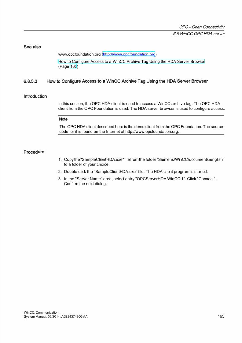
8/20/2019 WinCC Communication en-US en-US
http://slidepdf.com/reader/full/wincc-communication-en-us-en-us 165/527
See also
www.opcfoundation.org (http://www.opcfoundation.org)
How to Configure Access to a WinCC Archive Tag Using the HDA Server Browser (Page 165)
6.8.5.3 How to Configure Access to a WinCC Archive Tag Using the HDA Server Browser
Introduction
In this section, the OPC HDA client is used to access a WinCC archive tag. The OPC HDAclient from the OPC Foundation is used. The HDA server browser is used to configure access.
Note
The OPC HDA client described here is the demo client from the OPC Foundation. The sourcecode for it is found on the Internet at http://www.opcfoundation.org.
Procedure
1. Copy the "SampleClientHDA.exe" file from the folder "Siemens\WinCC\documents\english"to a folder of your choice.
2. Double-click the "SampleClientHDA.exe" file. The HDA client program is started.
3. In the "Server Name" area, select entry "OPCServerHDA.WinCC.1". Click "Connect".Confirm the next dialog.
OPC - Open Connectivity
6.8 WinCC OPC HDA server
WinCC: CommunicationSystem Manual, 06/2014, A5E34374800-AA 165
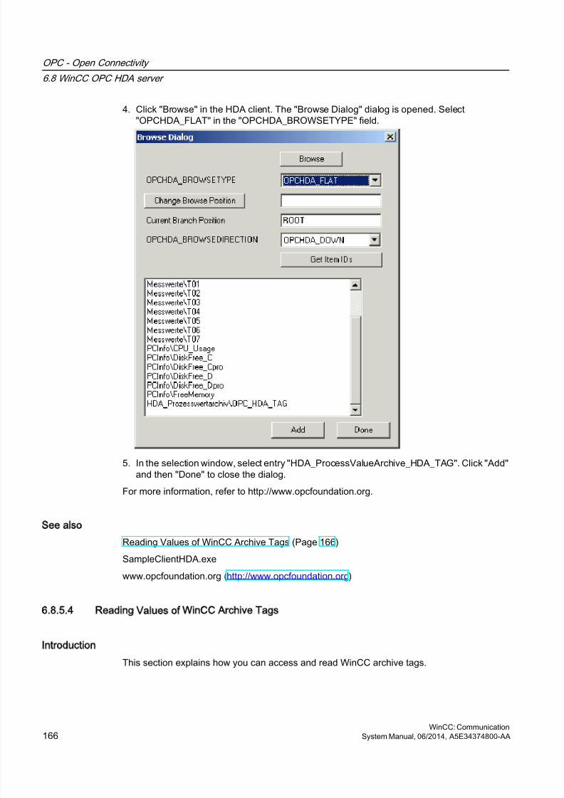
8/20/2019 WinCC Communication en-US en-US
http://slidepdf.com/reader/full/wincc-communication-en-us-en-us 166/527
4. Click "Browse" in the HDA client. The "Browse Dialog" dialog is opened. Select"OPCHDA_FLAT" in the "OPCHDA_BROWSETYPE" field.
5. In the selection window, select entry "HDA_ProcessValueArchive_HDA_TAG". Click "Add"and then "Done" to close the dialog.
For more information, refer to http://www.opcfoundation.org.
See also
Reading Values of WinCC Archive Tags (Page 166)
SampleClientHDA.exewww.opcfoundation.org (http://www.opcfoundation.org)
6.8.5.4 Reading Values of WinCC Archive Tags
Introduction
This section explains how you can access and read WinCC archive tags.
OPC - Open Connectivity
6.8 WinCC OPC HDA server
WinCC: Communication166 System Manual, 06/2014, A5E34374800-AA
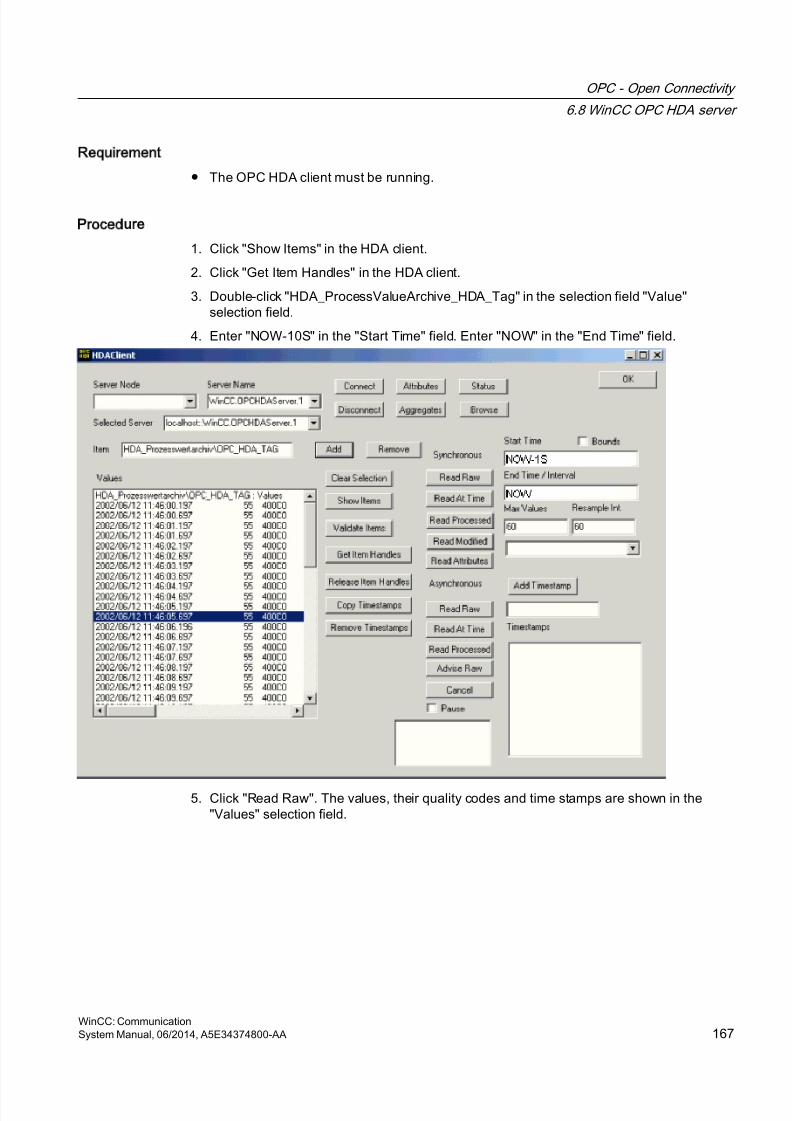
8/20/2019 WinCC Communication en-US en-US
http://slidepdf.com/reader/full/wincc-communication-en-us-en-us 167/527
Requirement
● The OPC HDA client must be running.
Procedure
1. Click "Show Items" in the HDA client.
2. Click "Get Item Handles" in the HDA client.
3. Double-click "HDA_ProcessValueArchive_HDA_Tag" in the selection field "Value"selection field.
4. Enter "NOW-10S" in the "Start Time" field. Enter "NOW" in the "End Time" field.
5. Click "Read Raw". The values, their quality codes and time stamps are shown in the"Values" selection field.
OPC - Open Connectivity
6.8 WinCC OPC HDA server
WinCC: CommunicationSystem Manual, 06/2014, A5E34374800-AA 167
8/20/2019 WinCC Communication en-US en-US
http://slidepdf.com/reader/full/wincc-communication-en-us-en-us 168/527
6.8.6 Special features of the OPC HDA server in WinCC for acyclic logging
Introduction
Tag logging is performed in WinCC cyclically or acyclically. The WinCC OPC HDA server worksdifferently depending on the logging method for tags:
● For all cyclically logged values, the OPC HDA server operates in conformity to the HDAspecification of the OPC foundation. The OPC aggregates are linearly interpolated.
● Acyclically logged tags are not included in the HDA specification of the OPC Foundation.The OPC aggregates are interpolated incrementally. Especially when a tag experiencesno change for a long period of time, no data is available during a time period. The followingshould be taken into consideration to nevertheless obtain valid data.
Note
The OPC HDA server is not OPC-compliant for acyclically logged tags. The HDAspecification of the OPC Foundation does not recognize acyclically logged tags and,therefore, no archive server can handle acyclically logged tags. The supported aggregatesare calculated in conformity to the OPC HDA specification. No non-explicitly calledfunctions are supported.
Note
If write access to process value archives is enabled, no future values may be added.
Configuration of acyclically logged tags
For the configuration of acyclically logged tags, the "Archive after segment change" settingneeds to be enabled for the tags. This enters the most recent valid value in the the new logwhen a segment changes.
Supported aggregates of the WinCC OPC HDA server for acyclically logged tags
The OPC HDA server supports the following aggregates:
● OPCHDA_MINIMUM
● OPCHDA_MAXIMUM
● OPCHDA_AVERAGE
● OPCHDA_END
● OPCHDA_INTERPOLATIVE
● OPCHDA_TIMEAVERAGE
● OPCHDA_TOTAL
● OPCHDA_DURATIONGOOD
● OPCHDA_PERCENTGOOD
OPC - Open Connectivity
6.8 WinCC OPC HDA server
WinCC: Communication168 System Manual, 06/2014, A5E34374800-AA
8/20/2019 WinCC Communication en-US en-US
http://slidepdf.com/reader/full/wincc-communication-en-us-en-us 169/527
Supported functions of the WinCC OPC HDA server for acyclically logged tags
● ReadRaw with "boundings" only. ReadRaw for a tag must always be performed with
"boundings", in order to find the last real stored value for an area without logged valuechange.
● ReadProcessed
● DeleteRaw
● DeleteAtTime
● Insert
● InsertReplace
● Replace
Calculating the aggregates for acyclically logged tags
Calculation of the aggregates is based on the extended "RawData" data record, which containsvirtual data points for the calculation in addition to real stored values. The WinCC OPC HDAserver prepares the contained "RawData" corresponding to the requirements of the"ReadProcessed". The virtual data points needed for the calculation are formed from thebordering real data points. The following significant points are included for the virtual datapoints:
● Value for the "StartTime"
● Value for the "EndTime"
● Value for interval limits
Example
The values for "00:59:00", "01:02:00" and "01:03:00" are stored for an acyclical tag loggingtags. An OPC HDA client postulates with "ReadProcessed" an aggregate with the followingparameters:
● StartTime = 01:00:00
● EndTime = 01:04:00
● Interval = 00:02:00
Note
The time period is always 1 µs less than the time stamp at the limit for the calculationwhen generating virtual values at limits ("EndTime"/"Interval").
A delta of 1 seconds is used in the following table to provide a better overview. The followinggraphic illustrates the example.
The OPC server uses the following "RawData" for the calculation of the aggregate:
OPC - Open Connectivity
6.8 WinCC OPC HDA server
WinCC: CommunicationSystem Manual, 06/2014, A5E34374800-AA 169
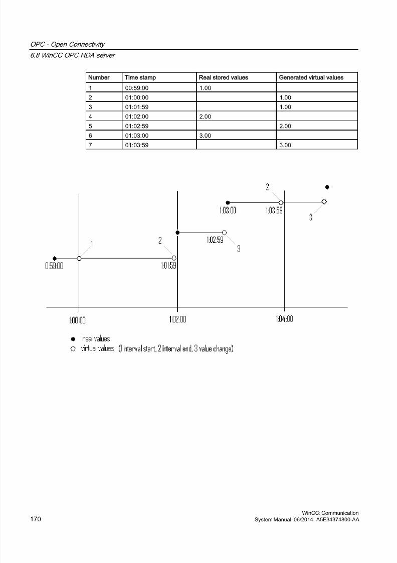
8/20/2019 WinCC Communication en-US en-US
http://slidepdf.com/reader/full/wincc-communication-en-us-en-us 170/527
Number Time stamp Real stored values Generated virtual values
1 00:59:00 1.00
2 01:00:00 1.003 01:01:59 1.00
4 01:02:00 2.00
5 01:02:59 2.00
6 01:03:00 3.00
7 01:03:59 3.00
OPC - Open Connectivity
6.8 WinCC OPC HDA server
WinCC: Communication170 System Manual, 06/2014, A5E34374800-AA
8/20/2019 WinCC Communication en-US en-US
http://slidepdf.com/reader/full/wincc-communication-en-us-en-us 171/527
6.9 WinCC OPC A&E Server
6.9.1 Functionality of the WinCC OPC A&E server
Introduction
The WinCC OPC A&E server is a DCOM application. The OPC A&E client is kept informed ofstatus changes for WinCC messages by means of subscriptions. The OPC A&E client canapply a filter to the subscription. This filter determines which messages and attributes aredisplayed.
The WinCC OPC A&E server supports the specification OPC Alarm&Event 1.10. This hasbeen confirmed by the compliance test.
The following chapter explains the display of the WinCC message system on OPC A&E, aswell as the attributes supported by the WinCC OPC A&E server. This is not a detaileddescription, but rather a summary of the most important information. For more information,refer to the "OPC Alarms & Events 1.10" specification.
Installation
The WinCC OPC A&E server can be selected during the installation of WinCC. Afterinstallation, the WinCC OPC A&E server is immediately available for use without any additionalconfiguration.
As of WinCC V6.2, the WinCC OPC A&E server can be used on a WinCC server and a WinCCclient.
Licensing
In order to operate the WinCC OPC A&E server, the following licenses must be installed oneach WinCC server implemented as an OPC A&E server:
● A valid RT license for WinCC
● WinCC Option Connectivity Pack
Server types
The WinCC OPC A&E server supports conditional events and simple events. In addition, thereare tracking events.
Condition-related event server
With a condition-related event server, the event is associated with a condition. A conditionmight, for example, be a limit value violation of a tag. A message is generated in WinCC assoon as the bounding value is exceeded. This message is shown as an alarm in OPC A&E.
OPC - Open Connectivity
6.9 WinCC OPC A&E Server
WinCC: CommunicationSystem Manual, 06/2014, A5E34374800-AA 171
8/20/2019 WinCC Communication en-US en-US
http://slidepdf.com/reader/full/wincc-communication-en-us-en-us 172/527
Simple event server
Simple events are messages that inform the OPC A&E client about events. Simple events
include, for example, starting or exiting programs.
Note
Note the following when using redundant systems:
Simple events interconnected to internal tags are sent twice when tags are updated.
The first message is triggered by the master, the second by the standby.
Tracking event server
If a change in a process occurs, the OPC A&E client receives a message. Such a change
might for example be a regulator adjustment.
OPC A&E client
All OPC A&E clients conforming to the OPC Alarms & Events 1.10 specification can accessthe WinCC OPC A&E server. You can also create the OPC A&E client yourself. By creatingproprietary OPC clients, most user-specific requirements can be met. An OPC A&E client can,for example, be used for the analysis and common archiving of alarms from multiple OPC A&Eservers.
See also
www.opcfoundation.org (http://www.opcfoundation.org)
Quality Codes for OPC A&E (Page 178)
Mapping of the WinCC Message System on OPC A&E (Page 172)
6.9.2 Mapping of the WinCC Message System on OPC A&E
6.9.2.1 Mapping of the WinCC Message System on OPC A&E
Introduction
During the configuration of the WinCC message system, settings are made to determine whichprocess events generate a message. This message is shown as an alarm in OPC A&E. Thetable below lists the most important parameters of the alarm. It also describes how theinformation is made available by the WinCC message system. For more information, refer to"Alarm Structure".
OPC - Open Connectivity
6.9 WinCC OPC A&E Server
WinCC: Communication172 System Manual, 06/2014, A5E34374800-AA
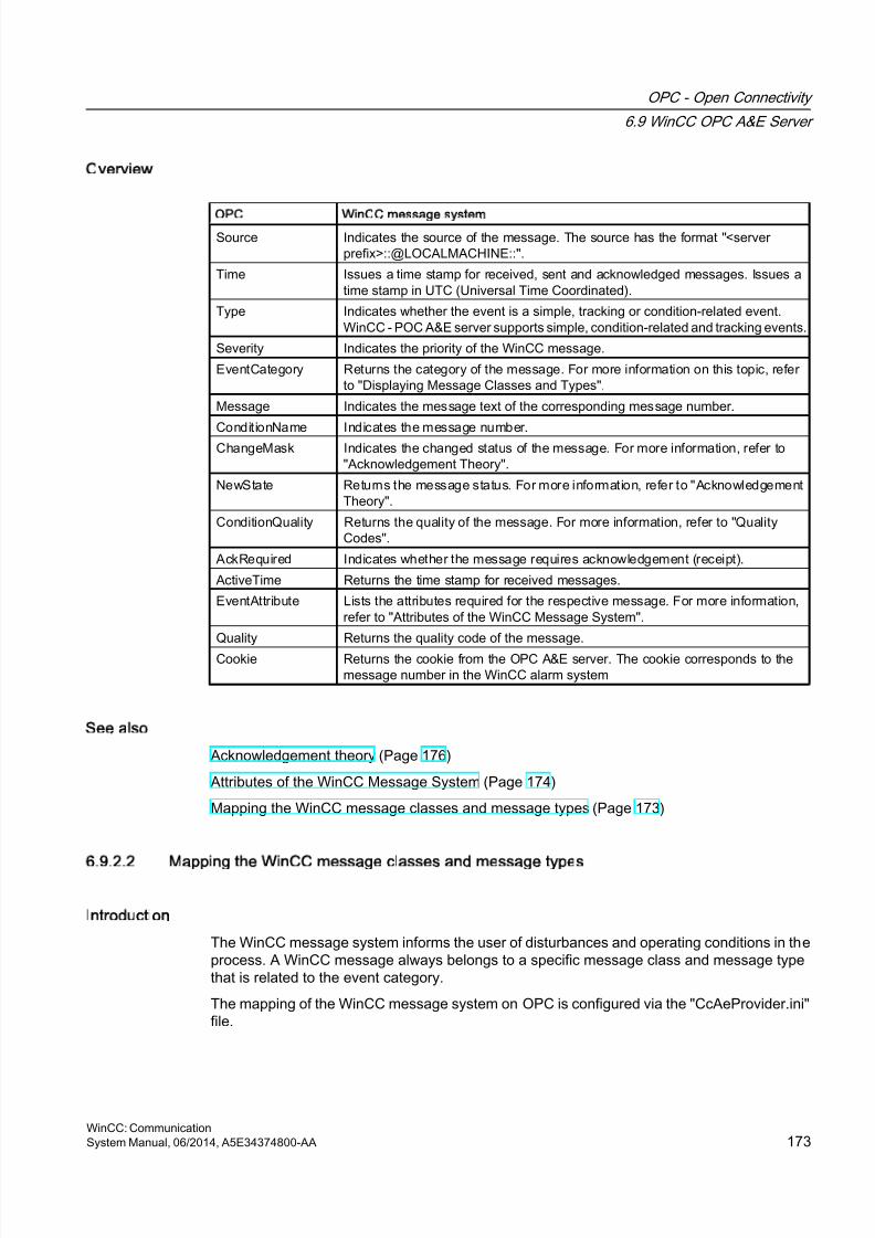
8/20/2019 WinCC Communication en-US en-US
http://slidepdf.com/reader/full/wincc-communication-en-us-en-us 173/527
Overview
OPC WinCC message system
Source Indicates the source of the message. The source has the format "<serverprefix>::@LOCALMACHINE::".
Time Issues a time stamp for received, sent and acknowledged messages. Issues atime stamp in UTC (Universal Time Coordinated).
Type Indicates whether the event is a simple, tracking or condition-related event.WinCC - POC A&E server supports simple, condition-related and tracking events.
Severity Indicates the priority of the WinCC message.
EventCategory Returns the category of the message. For more information on this topic, referto "Displaying Message Classes and Types".
Message Indicates the message text of the corresponding message number.
ConditionName Indicates the message number.ChangeMask Indicates the changed status of the message. For more information, refer to"Acknowledgement Theory".
NewState Returns the message status. For more information, refer to "AcknowledgementTheory".
ConditionQuality Returns the quality of the message. For more information, refer to "QualityCodes".
AckRequired Indicates whether the message requires acknowledgement (receipt).
ActiveTime Returns the time stamp for received messages.
EventAttribute Lists the attributes required for the respective message. For more information,refer to "Attributes of the WinCC Message System".
Quality Returns the quality code of the message.
Cookie Returns the cookie from the OPC A&E server. The cookie corresponds to themessage number in the WinCC alarm system
See also
Acknowledgement theory (Page 176)
Attributes of the WinCC Message System (Page 174)
Mapping the WinCC message classes and message types (Page 173)
6.9.2.2 Mapping the WinCC message classes and message types
Introduction
The WinCC message system informs the user of disturbances and operating conditions in theprocess. A WinCC message always belongs to a specific message class and message typethat is related to the event category.
The mapping of the WinCC message system on OPC is configured via the "CcAeProvider.ini"file.
OPC - Open Connectivity
6.9 WinCC OPC A&E Server
WinCC: CommunicationSystem Manual, 06/2014, A5E34374800-AA 173
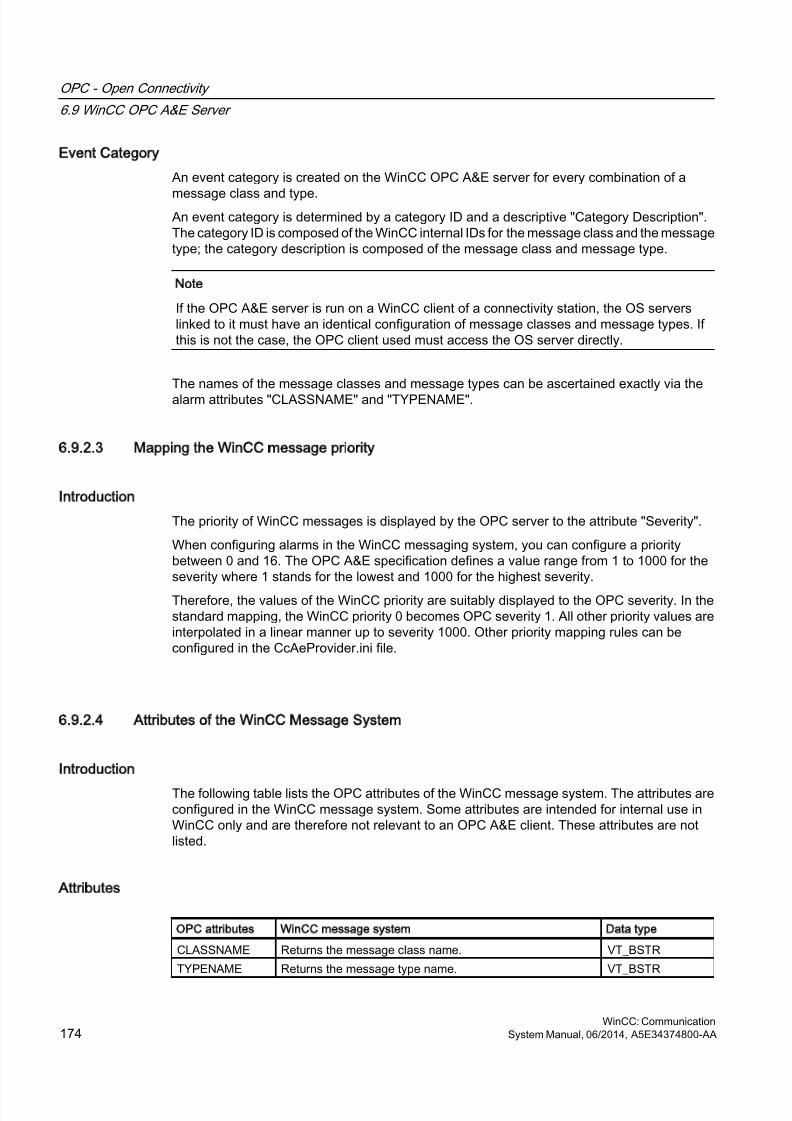
8/20/2019 WinCC Communication en-US en-US
http://slidepdf.com/reader/full/wincc-communication-en-us-en-us 174/527
Event Category
An event category is created on the WinCC OPC A&E server for every combination of a
message class and type.An event category is determined by a category ID and a descriptive "Category Description".The category ID is composed of the WinCC internal IDs for the message class and the messagetype; the category description is composed of the message class and message type.
Note
If the OPC A&E server is run on a WinCC client of a connectivity station, the OS serverslinked to it must have an identical configuration of message classes and message types. Ifthis is not the case, the OPC client used must access the OS server directly.
The names of the message classes and message types can be ascertained exactly via thealarm attributes "CLASSNAME" and "TYPENAME".
6.9.2.3 Mapping the WinCC message priority
Introduction
The priority of WinCC messages is displayed by the OPC server to the attribute "Severity".
When configuring alarms in the WinCC messaging system, you can configure a prioritybetween 0 and 16. The OPC A&E specification defines a value range from 1 to 1000 for theseverity where 1 stands for the lowest and 1000 for the highest severity.
Therefore, the values of the WinCC priority are suitably displayed to the OPC severity. In thestandard mapping, the WinCC priority 0 becomes OPC severity 1. All other priority values areinterpolated in a linear manner up to severity 1000. Other priority mapping rules can beconfigured in the CcAeProvider.ini file.
6.9.2.4 Attributes of the WinCC Message System
Introduction
The following table lists the OPC attributes of the WinCC message system. The attributes areconfigured in the WinCC message system. Some attributes are intended for internal use inWinCC only and are therefore not relevant to an OPC A&E client. These attributes are notlisted.
Attributes
OPC attributes WinCC message system Data type
CLASSNAME Returns the message class name. VT_BSTR
TYPENAME Returns the message type name. VT_BSTR
OPC - Open Connectivity
6.9 WinCC OPC A&E Server
WinCC: Communication174 System Manual, 06/2014, A5E34374800-AA
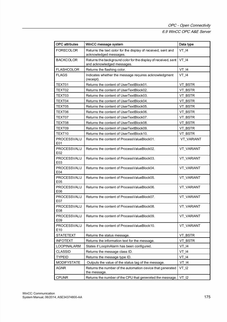
8/20/2019 WinCC Communication en-US en-US
http://slidepdf.com/reader/full/wincc-communication-en-us-en-us 175/527
OPC attributes WinCC message system Data type
FORECOLOR Returns the text color for the display of received, sent and
acknowledged messages.
VT_I4
BACKCOLOR Returns the background color for the display of received, sentand acknowledged messages.
VT_I4
FLASHCOLOR Returns the flashing color. VT_I4
FLAGS Indicates whether the message requires acknowledgment(receipt).
VT_I4
TEXT01 Returns the content of UserTextBlock01. VT_BSTR
TEXT02 Returns the content of UserTextBlock02. VT_BSTR
TEXT03 Returns the content of UserTextBlock03. VT_BSTR
TEXT04 Returns the content of UserTextBlock04. VT_BSTR
TEXT05 Returns the content of UserTextBlock05. VT_BSTR
TEXT06 Returns the content of UserTextBlock06. VT_BSTRTEXT07 Returns the content of UserTextBlock07. VT_BSTR
TEXT08 Returns the content of UserTextBlock08. VT_BSTR
TEXT09 Returns the content of UserTextBlock09. VT_BSTR
TEXT10 Returns the content of UserTextBlock10. VT_BSTR
PROCESSVALUE01
Returns the content of ProcessValueBlock01. VT_VARIANT
PROCESSVALUE02
Returns the content of ProcessValueBlock02. VT_VARIANT
PROCESSVALUE03
Returns the content of ProcessValueBlock03. VT_VARIANT
PROCESSVALUE04 Returns the content of ProcessValueBlock04. VT_VARIANT
PROCESSVALUE05
Returns the content of ProcessValueBlock05. VT_VARIANT
PROCESSVALUE06
Returns the content of ProcessValueBlock06. VT_VARIANT
PROCESSVALUE07
Returns the content of ProcessValueBlock07. VT_VARIANT
PROCESSVALUE08
Returns the content of ProcessValueBlock08. VT_VARIANT
PROCESSVALUE09
Returns the content of ProcessValueBlock09. VT_VARIANT
PROCESSVALUE10
Returns the content of ProcessValueBlock10. VT_VARIANT
STATETEXT Returns the status message. VT_BSTR
INFOTEXT Returns the information text for the message. VT_BSTR
LOOPINALARM States if LoopInAlarm has been configured. VT_I4
CLASSID Returns the message class ID. VT_I4
TYPEID Returns the message type ID. VT_I4
MODIFYSTATE Outputs the value of the status tag of the message. VT_I4
AGNR Returns the number of the automation device that generatedthe message.
VT_I2
CPUNR Returns the number of the CPU that generated the message. VT_I2
OPC - Open Connectivity
6.9 WinCC OPC A&E Server
WinCC: CommunicationSystem Manual, 06/2014, A5E34374800-AA 175
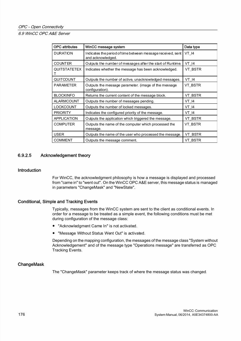
8/20/2019 WinCC Communication en-US en-US
http://slidepdf.com/reader/full/wincc-communication-en-us-en-us 176/527
OPC attributes WinCC message system Data type
DURATION Indicates the period of time between message received, sent
and acknowledged.
VT_I4
COUNTER Outputs the number of messages after the start of Runtime. VT_I4
QUITSTATETEXT
Indicates whether the message has been acknowledged. VT_BSTR
QUITCOUNT Outputs the number of active, unacknowledged messages. VT_I4
PARAMETER Outputs the message parameter. (image of the messageconfiguration).
VT_BSTR
BLOCKINFO Returns the current content of the message block. VT_BSTR
ALARMCOUNT Outputs the number of messages pending. VT_I4
LOCKCOUNT Outputs the number of locked messages. VT_I4
PRIORITY Indicates the configured priority of the message. VT_I4
APPLICATION Outputs the application which triggered the message. VT_BSTRCOMPUTER Outputs the name of the computer which processed the
message.VT_BSTR
USER Outputs the name of the user who processed the message. VT_BSTR
COMMENT Outputs the message comment. VT_BSTR
6.9.2.5 Acknowledgement theory
Introduction
For WinCC, the acknowledgment philosophy is how a message is displayed and processedfrom "came in" to "went out". On the WinCC OPC A&E server, this message status is managedin parameters "ChangeMask" and "NewState".
Conditional, Simple and Tracking Events
Typically, messages from the WinCC system are sent to the client as conditional events. Inorder for a message to be treated as a simple event, the following conditions must be metduring configuration of the message class:
● "Acknowledgment Came In" is not activated.
● "Message Without Status Went Out" is activated.
Depending on the mapping configuration, the messages of the message class "System withoutAcknowledgement" and of the message type "Operations message" are transferred as OPCTracking Events.
ChangeMask
The "ChangeMask" parameter keeps track of where the message status was changed.
OPC - Open Connectivity
6.9 WinCC OPC A&E Server
WinCC: Communication176 System Manual, 06/2014, A5E34374800-AA
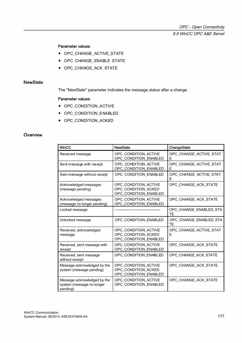
8/20/2019 WinCC Communication en-US en-US
http://slidepdf.com/reader/full/wincc-communication-en-us-en-us 177/527
Parameter values:
● OPC_CHANGE_ACTIVE_STATE
● OPC_CHANGE_ENABLE_STATE
● OPC_CHANGE_ACK_STATE
NewState
The "NewState" parameter indicates the message status after a change.
Parameter values:
● OPC_CONDITION_ACTIVE
● OPC_CONDITION_ENABLED
● OPC_CONDITION_ACKED
Overview
WinCC NewState ChangeState
Received message OPC_CONDITION_ACTIVEOPC_CONDITION_ENABLED
OPC_CHANGE_ACTIVE_STATE
Sent message with receipt OPC_CONDITION_ACTIVEOPC_CONDITION_ENABLED
OPC_CHANGE_ACTIVE_STATE
Sent message without receipt OPC_CONDITION_ENABLED OPC_CHANGE_ACTIVE_STAT
EAcknowledged messages(message pending)
OPC_CONDITION_ACTIVEOPC_CONDITION_ACKEDOPC_CONDITION_ENABLED
OPC_CHANGE_ACK_STATE
Acknowledged messages(message no longer pending)
OPC_CONDITION_ACTIVEOPC_CONDITION_ENABLED
OPC_CHANGE_ACK_STATE
Locked message -------------------------------------- OPC_CHANGE_ENABLED_STATE
Unlocked message OPC_CONDITION_ENABLED OPC_CHANGE_ENABLED_STATE
Received, acknowledgedmessage
OPC_CONDITION_ACTIVEOPC_CONDITION_ACKED
OPC_CONDITION_ENABLED
OPC_CHANGE_ACTIVE_STATE
Received, sent message withreceipt
OPC_CONDITION_ACTIVEOPC_CONDITION_ENABLED
OPC_CHANGE_ACK_STATE
Received, sent messagewithout receipt
OPC_CONDITION_ENABLED OPC_CHANGE_ACK_STATE
Message acknowledged by thesystem (message pending)
OPC_CONDITION_ACTIVEOPC_CONDITION_ACKEDOPC_CONDITION_ENABLED
OPC_CHANGE_ACK_STATE
Message acknowledged by thesystem (message no longerpending)
OPC_CONDITION_ACTIVEOPC_CONDITION_ENABLED
OPC_CHANGE_ACK_STATE
OPC - Open Connectivity
6.9 WinCC OPC A&E Server
WinCC: CommunicationSystem Manual, 06/2014, A5E34374800-AA 177
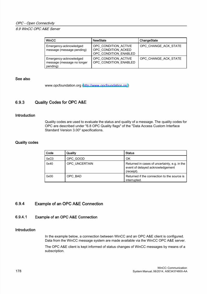
8/20/2019 WinCC Communication en-US en-US
http://slidepdf.com/reader/full/wincc-communication-en-us-en-us 178/527
WinCC NewState ChangeState
Emergency-acknowledged
message (message pending)
OPC_CONDITION_ACTIVE
OPC_CONDITION_ACKEDOPC_CONDITION_ENABLED
OPC_CHANGE_ACK_STATE
Emergency-acknowledgedmessage (message no longerpending)
OPC_CONDITION_ACTIVEOPC_CONDITION_ENABLED
OPC_CHANGE_ACK_STATE
See also
www.opcfoundation.org (http://www.opcfoundation.org)
6.9.3 Quality Codes for OPC A&E
Introduction
Quality codes are used to evaluate the status and quality of a message. The quality codes forOPC are described under "6.8 OPC Quality flags" of the "Data Access Custom InterfaceStandard Version 3.00" specifications.
Quality codes
Code Quality Status
0xC0 OPC_GOOD OK
0x40 OPC_UNCERTAIN Returned in cases of uncertainty, e.g. in theevent of delayed acknowledgement(receipt).
0x00 OPC_BAD Returned if the connection to the source isinterrupted.
6.9.4 Example of an OPC A&E Connection
6.9.4.1 Example of an OPC A&E Connection
Introduction
In the example below, a connection between WinCC and an OPC A&E client is configured.Data from the WinCC message system are made available via the WinCC OPC A&E server.
The OPC A&E client is kept informed of status changes of WinCC messages by means of asubscription.
OPC - Open Connectivity
6.9 WinCC OPC A&E Server
WinCC: Communication178 System Manual, 06/2014, A5E34374800-AA
8/20/2019 WinCC Communication en-US en-US
http://slidepdf.com/reader/full/wincc-communication-en-us-en-us 179/527
All OPC A&E clients conforming to the OPC Alarms&Events 1.10 specifications can accessthe WinCC OPC A&E server.
Configuration Step
The following configurations are required for connection between WinCC and the OPC A&Eclient:
1. Configuring access to the WinCC message system
See also
How to Configure Access to the WinCC Message System (Page 179)
www.opcfoundation.org (http://www.opcfoundation.org)
6.9.4.2 How to Configure Access to the WinCC Message System
Introduction
In this section, the OPC A&E client of the OPC foundation accesses the WinCC messagesystem.
Note
The OPC A&E client described here is the demo client from the OPC Foundation. The sourcecode for it is found on the Internet at http://www.opcfoundation.org.
Requirement
● Create several internal tags of the "binary" data type in the WinCC project of the WinCCOPC A&E server.
● Configure the WinCC message system in the WinCC project of the WinCC OPC A&Eserver. Link the messages to the internal tags.
● Configure a picture with the Graphics Designer. Add the WinCC alarm control and an I/Ofield to the picture. Link the message tags to the graphic objects.
● Enable the "Alarm Logging Runtime" in the start list.
● Enable the WinCC project of the WinCC OPC A&E server.
Procedure
1. Copy the "SampleClientAE.exe" file from the folder "Siemens\WinCC\documents\english"to a folder of your choice. This application is only available in the online help.
2. Select "OPC" >"Connect..." in the menu bar. Select "OPC.WinCC-AlarmsEvent" in the"OPC Alarm Server" dialog. Click "OK" to close the dialog.
OPC - Open Connectivity
6.9 WinCC OPC A&E Server
WinCC: CommunicationSystem Manual, 06/2014, A5E34374800-AA 179
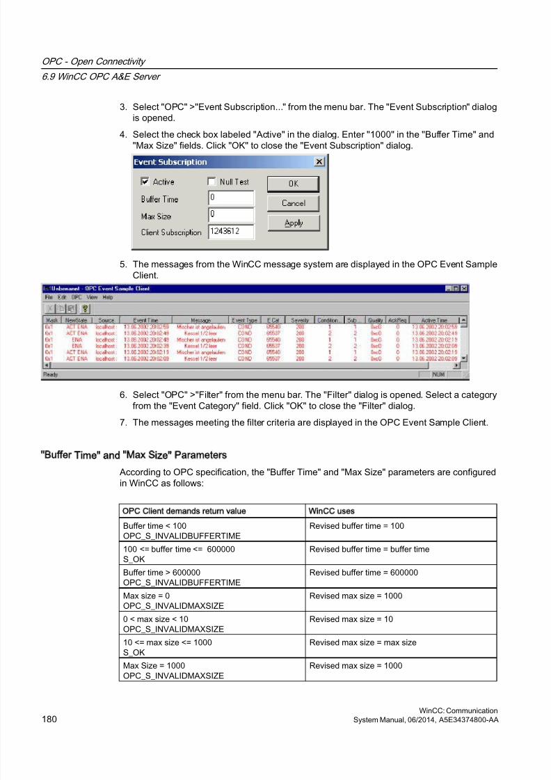
8/20/2019 WinCC Communication en-US en-US
http://slidepdf.com/reader/full/wincc-communication-en-us-en-us 180/527
3. Select "OPC" >"Event Subscription..." from the menu bar. The "Event Subscription" dialogis opened.
4. Select the check box labeled "Active" in the dialog. Enter "1000" in the "Buffer Time" and"Max Size" fields. Click "OK" to close the "Event Subscription" dialog.
5. The messages from the WinCC message system are displayed in the OPC Event Sample
Client.
6. Select "OPC" >"Filter" from the menu bar. The "Filter" dialog is opened. Select a category
from the "Event Category" field. Click "OK" to close the "Filter" dialog.7. The messages meeting the filter criteria are displayed in the OPC Event Sample Client.
Buffer Time and Max Size Parameters
According to OPC specification, the "Buffer Time" and "Max Size" parameters are configuredin WinCC as follows:
OPC Client demands return value WinCC uses
Buffer time < 100OPC_S_INVALIDBUFFERTIME
Revised buffer time = 100
100 <= buffer time <= 600000S_OK
Revised buffer time = buffer time
Buffer time > 600000OPC_S_INVALIDBUFFERTIME
Revised buffer time = 600000
Max size = 0OPC_S_INVALIDMAXSIZE
Revised max size = 1000
0 < max size < 10OPC_S_INVALIDMAXSIZE
Revised max size = 10
10 <= max size <= 1000S_OK
Revised max size = max size
Max Size = 1000OPC_S_INVALIDMAXSIZE
Revised max size = 1000
OPC - Open Connectivity
6.9 WinCC OPC A&E Server
WinCC: Communication180 System Manual, 06/2014, A5E34374800-AA
8/20/2019 WinCC Communication en-US en-US
http://slidepdf.com/reader/full/wincc-communication-en-us-en-us 181/527
Parameters may be set while creating a subscription. However, you cannot change an existingsubscription using SetState() after the fact.
For more information, refer to http://www.opcfoundation.org.
See also
www.opcfoundation.org (http://www.opcfoundation.org)
6.9.5 OPC A&E server with hierarchical access
6.9.5.1 Functionality of the OPC A&E server
Introduction
The OPC-A&E server uses DCOM services for transferring messages between OPC-capableapplications. The OPC A&E server supports the specification OPC Alarm&Event 1.10.
The following chapter explains the mapping of the WinCC message system on OPC A&E withhierarchical access and the attributes supported by the OPC A&E server. This documentationincludes an overview of the specific information. For more information, refer to the "OPC Alarms& Events 1.10" specification.
Principle of operation
The OPC-A&E client receives WinCC messages via subscription. You can use the subscriptionfilter to reduce the number of events that will be transferred with a subscription. The OPC-A&Eclient can be set for every event category that displays message attributes.
Installation
The WinCC OPC A&E server can be selected during the installation of WinCC. Afterinstallation, the WinCC OPC A&E server is immediately available for use without any additionalconfiguration.
As of WinCC V6.2, the WinCC OPC A&E server can be used on a WinCC server and a WinCC
client.
Licensing
In order to operate the OPC A&E server, one of the following licenses must be installed oneach computer running an OPC A&E server:
● A valid RT license for WinCC
● WinCC Option Connectivity Pack
OPC - Open Connectivity
6.9 WinCC OPC A&E Server
WinCC: CommunicationSystem Manual, 06/2014, A5E34374800-AA 181

8/20/2019 WinCC Communication en-US en-US
http://slidepdf.com/reader/full/wincc-communication-en-us-en-us 182/527
Event types
The OPC-A&E server with hierarchical access supports conditional events, simple events and
tracking events.
Condition related events
With a condition related event, the event is associated with a condition. A condition might, forexample, be a limit value violation of a tag. This limit violation generates a message that isshown as an alarm with OPC A&E.
Simple events
Simple events are messages that inform the OPC A&E client about events. Simple eventsinclude, for example, starting or exiting programs.
Note
Note the following when using redundant systems:
Simple events interconnected to internal tags are sent twice when tags are updated.
The first message is triggered by the master, the second by the standby.
Tracking events
A tracking event is sent with a operator input message to the OPC A&E client. An operatorinput message is triggered by manual intervention in the process.
OPC A&E client
All OPC A&E clients conforming to the OPC Alarms & Events 1.10 specification can accessthe OPC A&E server. You can also create the OPC A&E client yourself. By creating proprietaryOPC clients, most user-specific requirements can be met. An OPC A&E client, for example,may be used for analysis and joint archiving of alarms from different OPC A&E servers. Theacknowledgement of archived messages is not possible; only current alarms and events canbe acknowledged.
Note
Documentation on OPC
You can find additional information on OPC in the Chapter "Interfaces > OPC - OLE for
Process Control".
OPC - Open Connectivity
6.9 WinCC OPC A&E Server
WinCC: Communication182 System Manual, 06/2014, A5E34374800-AA
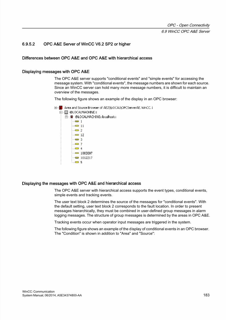
8/20/2019 WinCC Communication en-US en-US
http://slidepdf.com/reader/full/wincc-communication-en-us-en-us 183/527
6.9.5.2 OPC A&E Server of WinCC V6.2 SP2 or higher
Differences between OPC A&E and OPC A&E with hierarchical access
Displaying messages with OPC A&E
The OPC A&E server supports "conditional events" and "simple events" for accessing themessage system. With "conditional events", the message numbers are shown for each source.Since an WinCC server can hold many more message numbers, it is difficult to maintain anoverview of the messages.
The following figure shows an example of the display in an OPC browser:
Displaying the messages with OPC A&E and hierarchical access
The OPC A&E server with hierarchical access supports the event types, conditional events,simple events and tracking events.
The user text block 2 determines the source of the messages for "conditional events". Withthe default setting, user text block 2 corresponds to the fault location. In order to presentmessages hierarchically, they must be combined in user-defined group messages in alarmlogging messages. The structure of group messages is determined by the areas in OPC A&E.
Tracking events occur when operator input messages are triggered in the system.
The following figure shows an example of the display of conditional events in an OPC browser.The "Condition" is shown in addition to "Area" and "Source":
OPC - Open Connectivity
6.9 WinCC OPC A&E Server
WinCC: CommunicationSystem Manual, 06/2014, A5E34374800-AA 183
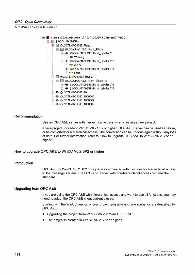
8/20/2019 WinCC Communication en-US en-US
http://slidepdf.com/reader/full/wincc-communication-en-us-en-us 184/527
Recommendation
Use an OPC A&E server with hierarchical access when creating a new project.
After a project upgrade to WinCC V6.2 SP2 or higher, OPC A&E Server can be used as before,or be converted for hierarchical access. The conversion can be undone again without any lossof data. For further information, refer to "How to upgrade OPC A&E to WinCC V6.2 SP2 orhigher".
How to upgrade OPC A&E to WinCC V6.2 SP2 or higher
Introduction
OPC A&E for WinCC V6.2 SP2 or higher was enhanced with functions for hierarchical accessto the message system. The OPC-A&E server with non-hierarchical access remains thestandard.
Upgrading from OPC A&E
If you are using the OPC A&E with hierarchical access and want to use all functions, you mayneed to adapt the OPC A&E client currently used.
Starting with the WinCC version of your project, possible upgrade scenarios are described forOPC A&E:
● Upgrading the project from WinCC V6.2 to WinCC V6.2 SP2
● The project is created in WinCC V6.2 SP2 or higher.
OPC - Open Connectivity
6.9 WinCC OPC A&E Server
WinCC: Communication184 System Manual, 06/2014, A5E34374800-AA
8/20/2019 WinCC Communication en-US en-US
http://slidepdf.com/reader/full/wincc-communication-en-us-en-us 185/527
Upgrading from WinCC V6.2 to WinCC V6.2 SP2
You can upgrade a project with WinCC V6.2 to WinCC V6.2 SP2 in regard to OPC A&E as
follows:
Retaining previous OPC A&E without hierarchical access
If you want to continue to work with the previously used OPC A&E server, the followingscenarios are possible:
● If you have not changed the standard "CcAeProvider.ini" file, you do not need to make anyother settings.
● If you have changed the standard "CcAeProvider.ini" file and want to keep these changes,proceed as follows:
– Save the "CcAeProvider.ini" file from the WinCC installation path in the "OPC\AlarmEvent\bin" folder.
If you are working on a distributed system or a system integrated in STEP 7, save thefile from the project on the WinCC client or on the OS.
– Following the upgrade, copy the file into the WinCC project directory.If you are working on a distributed system or a system integrated in STEP 7, copy thefile on the WinCC server or on the ES into the project directory of the client projects orOS projects.
● If you have changed the standard "CcAeProvider.ini" file and want to replace it with thestandard "CcAeProvider.ini" file supplied with the product, before the upgrade delete thesefiles on the servers and clients or on the ES computers and OS computers. The projectfolder is located in "wincproj" sub-folder on the ES.
Switching to OPC A&E with hierarchical access
If you want to work with the OPC A&E server with hierarchical access, proceed as follows:
1. After upgrading, copy the "CcAeProvider.ini" file to the project folder. The file is located inthe WinCC installation path in the folder "OPC\AlarmEvent\Hierarchical-Access".
2. Update the clients or perform a complete download for the OS servers.
Creating a project in WinCC V6.2 SP2 or higher
New projects created in WinCC V6.2 SP2 or higher still use OPC A&E Server without
hierarchical access. You do not have to make any additional settings.If you want to work with the OPC A&E server with hierarchical access, proceed as follows:
1. After upgrading, copy the "CcAeProvider.ini" file to the project folder of the ES projects.You can find the file in the "OPC\AlarmEvent\Hierarchical-Access" folder below theinstallation path of WinCC.
2. Update the clients or perform a complete download for the OS servers.
OPC - Open Connectivity
6.9 WinCC OPC A&E Server
WinCC: CommunicationSystem Manual, 06/2014, A5E34374800-AA 185
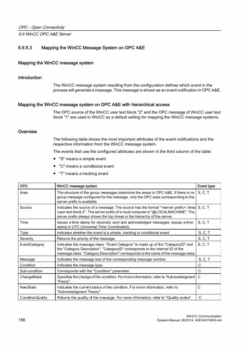
8/20/2019 WinCC Communication en-US en-US
http://slidepdf.com/reader/full/wincc-communication-en-us-en-us 186/527
6.9.5.3 Mapping the WinCC Message System on OPC A&E
Mapping the WinCC message system
Introduction
The WinCC message system resulting from the configuration defines which event in theprocess will generate a message. This message is shown as an event notification in OPC A&E.
Mapping the WinCC message system on OPC A&E with hierarchical access
The OPC source of the WinCC user text block "2" and the OPC message of WinCC user textblock "1" are used in WinCC as a default setting for mapping the WinCC message systems.
Overview
The following table shows the most important attributes of the event notifications and therespective information from the WinCC message system.
The events that use the configured attributes are shown in the third column of the table:
● "S" means a simple event
● "C" means a conditional event
● "T" means a tracking event
OPC WinCC message system Event type
Area The structure of the group messages determine the areas in OPC A&E. If there is nogroup message configured for the message, only the OPC area corresponding to theserver prefix is available.
S, C, T
Source Indicates the source of a message. The source has the format "<server prefix>::Area\user text block 2". The server prefix of a local computer is "@LOCALMACHINE". Theserver prefix always shows the top Areas in the hierarchy of the server.
S, C, T
Time Issues a time stamp for received, sent and acknowledged messages. Issues a timestamp in UTC (Universal Time Coordinated).
S, C, T
Type Indicates whether the event is a simple, tracking or conditional event. S, C, T
Severity Returns the priority of the message. S, C, T
EventCategory Indicates the message class. "Event Category" is made up of the "CategoryID" andthe "Category Description". "CategoryID" corresponds to the internal ID of themessage class. "Category Description" corresponds to the name of the message class.
S, C, T
Message Indicates the message text of the corresponding message number. S, C, T
Condition Indicates the message type. C
Sub-condition Corresponds with the "Condition" parameter. C
ChangeMask Specifies the change of the condition. For more information, refer to "AcknowledgmentTheory".
C
NewState Indicates the current status of the condition. For more information, refer to"Acknowledgment Theory".
C
ConditionQuality Returns the quality of the message. For more information, refer to "Quality codes". C
OPC - Open Connectivity
6.9 WinCC OPC A&E Server
WinCC: Communication186 System Manual, 06/2014, A5E34374800-AA
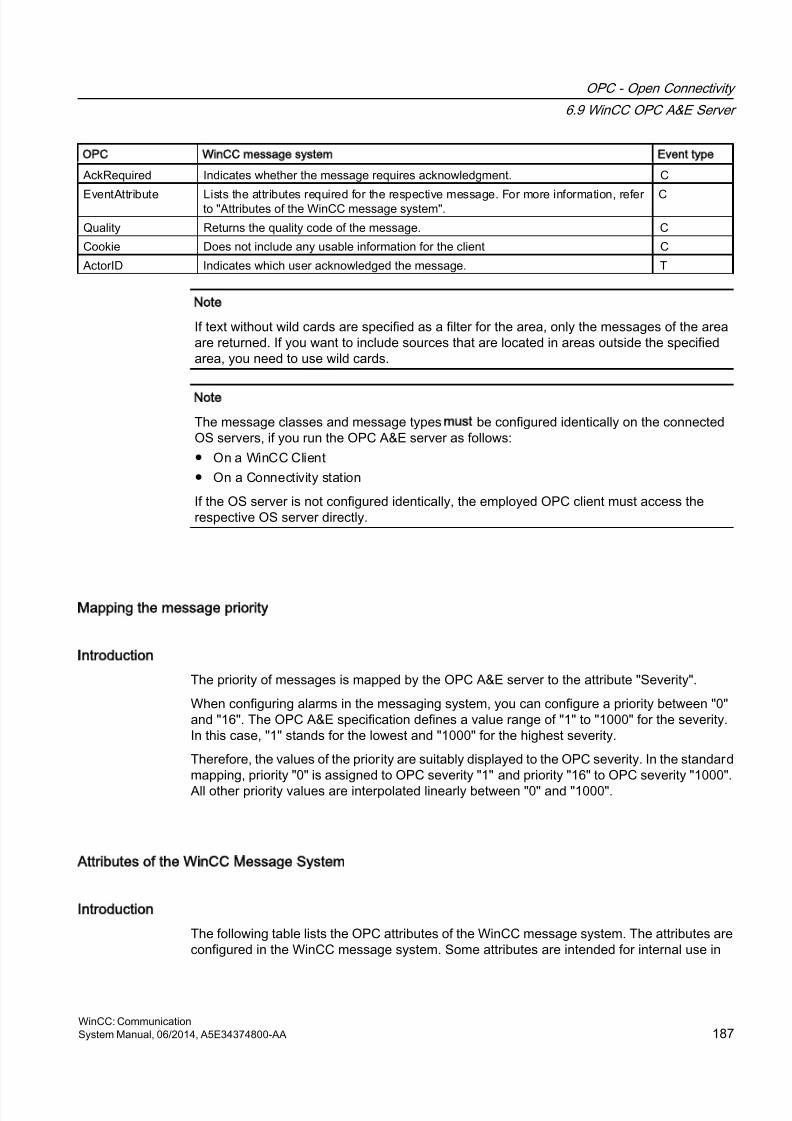
8/20/2019 WinCC Communication en-US en-US
http://slidepdf.com/reader/full/wincc-communication-en-us-en-us 187/527
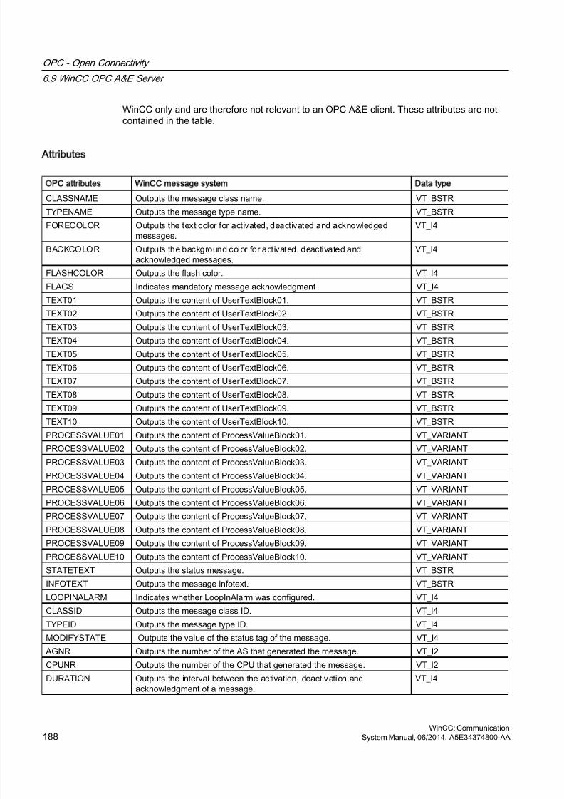
8/20/2019 WinCC Communication en-US en-US
http://slidepdf.com/reader/full/wincc-communication-en-us-en-us 188/527
WinCC only and are therefore not relevant to an OPC A&E client. These attributes are notcontained in the table.
Attributes
OPC attributes WinCC message system Data type
CLASSNAME Outputs the message class name. VT_BSTR
TYPENAME Outputs the message type name. VT_BSTR
FORECOLOR Outputs the text color for activated, deactivated and acknowledgedmessages.
VT_I4
BACKCOLOR Outputs the background color for activated, deactivated andacknowledged messages.
VT_I4
FLASHCOLOR Outputs the flash color. VT_I4
FLAGS Indicates mandatory message acknowledgment VT_I4
TEXT01 Outputs the content of UserTextBlock01. VT_BSTR
TEXT02 Outputs the content of UserTextBlock02. VT_BSTR
TEXT03 Outputs the content of UserTextBlock03. VT_BSTR
TEXT04 Outputs the content of UserTextBlock04. VT_BSTR
TEXT05 Outputs the content of UserTextBlock05. VT_BSTR
TEXT06 Outputs the content of UserTextBlock06. VT_BSTR
TEXT07 Outputs the content of UserTextBlock07. VT_BSTR
TEXT08 Outputs the content of UserTextBlock08. VT_BSTR
TEXT09 Outputs the content of UserTextBlock09. VT_BSTR
TEXT10 Outputs the content of UserTextBlock10. VT_BSTRPROCESSVALUE01 Outputs the content of ProcessValueBlock01. VT_VARIANT
PROCESSVALUE02 Outputs the content of ProcessValueBlock02. VT_VARIANT
PROCESSVALUE03 Outputs the content of ProcessValueBlock03. VT_VARIANT
PROCESSVALUE04 Outputs the content of ProcessValueBlock04. VT_VARIANT
PROCESSVALUE05 Outputs the content of ProcessValueBlock05. VT_VARIANT
PROCESSVALUE06 Outputs the content of ProcessValueBlock06. VT_VARIANT
PROCESSVALUE07 Outputs the content of ProcessValueBlock07. VT_VARIANT
PROCESSVALUE08 Outputs the content of ProcessValueBlock08. VT_VARIANT
PROCESSVALUE09 Outputs the content of ProcessValueBlock09. VT_VARIANT
PROCESSVALUE10 Outputs the content of ProcessValueBlock10. VT_VARIANTSTATETEXT Outputs the status message. VT_BSTR
INFOTEXT Outputs the message infotext. VT_BSTR
LOOPINALARM Indicates whether LoopInAlarm was configured. VT_I4
CLASSID Outputs the message class ID. VT_I4
TYPEID Outputs the message type ID. VT_I4
MODIFYSTATE Outputs the value of the status tag of the message. VT_I4
AGNR Outputs the number of the AS that generated the message. VT_I2
CPUNR Outputs the number of the CPU that generated the message. VT_I2
DURATION Outputs the interval between the activation, deactivation andacknowledgment of a message.
VT_I4
OPC - Open Connectivity
6.9 WinCC OPC A&E Server
WinCC: Communication188 System Manual, 06/2014, A5E34374800-AA
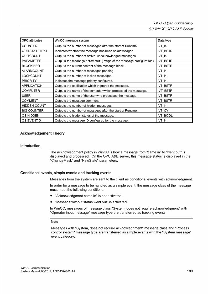
8/20/2019 WinCC Communication en-US en-US
http://slidepdf.com/reader/full/wincc-communication-en-us-en-us 189/527
OPC attributes WinCC message system Data type
COUNTER Outputs the number of messages after the start of Runtime. VT_I4
QUITSTATETEXT Indicates whether the message has been acknowledged. VT_BSTRQUITCOUNT Outputs the number of active, unacknowledged messages. VT_I4
PARAMETER Outputs the message parameter. (image of the message configuration). VT_BSTR
BLOCKINFO Outputs the current content of the message block. VT_BSTR
ALARMCOUNT Outputs the number of messages pending. VT_I4
LOCKCOUNT Outputs the number of locked messages. VT_I4
PRIORITY Indicates the message priority configured. VT_I4
APPLICATION Outputs the application which triggered the message. VT_BSTR
COMPUTER Outputs the name of the computer which processed the message. VT_BSTR
USER Outputs the name of the user who processed the message. VT_BSTR
COMMENT Outputs the message comment. VT_BSTR
HIDDEN-COUNT Outputs the number of hidden messages. VT_I4
BIG COUNTER Outputs the number of messages after the start of Runtime. VT_CY
OS-HIDDEN Outputs the hidden status of the message. VT_BOOL
OS-EVENTID Outputs the message ID configured for the message. VT_I4
Acknowledgement Theory
Introduction
The acknowledgment policy in WinCC is how a message from "came in" to "went out" isdisplayed and processed . On the OPC A&E server, this message status is displayed in the"ChangeMask" and "NewState" parameters.
Conditional events, simple events and tracking events
Messages from the system are sent to the client as conditional events with acknowledgment.
In order for a message to be handled as a simple event, the message class of the messagemust meet the following conditions:
● "Acknowledgment came in" is not activated.
● "Message without status went out" is activated.
In WinCC, messages of message class "System, does not require acknowledgment" with"Operator input message" message type are transferred as tracking events.
Note
Messages with "System, does not require acknowledgment" message class and "Processcontrol system" message type are transferred as simple events with the "System message"event category.
OPC - Open Connectivity
6.9 WinCC OPC A&E Server
WinCC: CommunicationSystem Manual, 06/2014, A5E34374800-AA 189
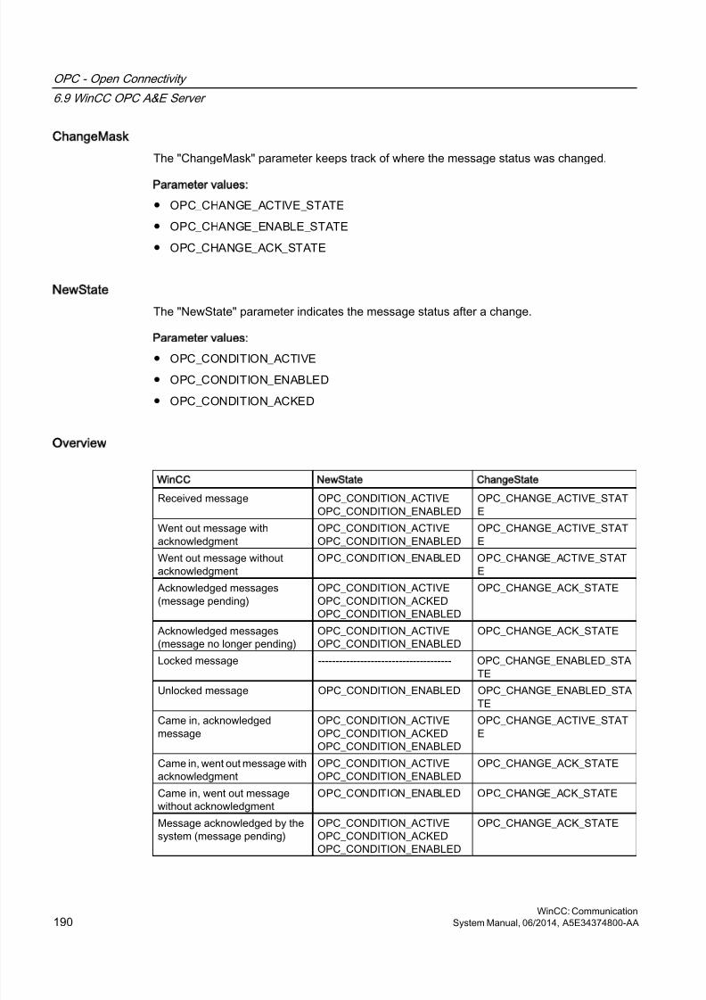
8/20/2019 WinCC Communication en-US en-US
http://slidepdf.com/reader/full/wincc-communication-en-us-en-us 190/527
ChangeMask
The "ChangeMask" parameter keeps track of where the message status was changed.
Parameter values:
● OPC_CHANGE_ACTIVE_STATE
● OPC_CHANGE_ENABLE_STATE
● OPC_CHANGE_ACK_STATE
NewState
The "NewState" parameter indicates the message status after a change.
Parameter values:
● OPC_CONDITION_ACTIVE
● OPC_CONDITION_ENABLED
● OPC_CONDITION_ACKED
Overview
WinCC NewState ChangeState
Received message OPC_CONDITION_ACTIVEOPC_CONDITION_ENABLED
OPC_CHANGE_ACTIVE_STATE
Went out message withacknowledgment
OPC_CONDITION_ACTIVEOPC_CONDITION_ENABLED
OPC_CHANGE_ACTIVE_STATE
Went out message withoutacknowledgment
OPC_CONDITION_ENABLED OPC_CHANGE_ACTIVE_STATE
Acknowledged messages(message pending)
OPC_CONDITION_ACTIVEOPC_CONDITION_ACKEDOPC_CONDITION_ENABLED
OPC_CHANGE_ACK_STATE
Acknowledged messages(message no longer pending)
OPC_CONDITION_ACTIVEOPC_CONDITION_ENABLED
OPC_CHANGE_ACK_STATE
Locked message -------------------------------------- OPC_CHANGE_ENABLED_STATE
Unlocked message OPC_CONDITION_ENABLED OPC_CHANGE_ENABLED_STA
TECame in, acknowledgedmessage
OPC_CONDITION_ACTIVEOPC_CONDITION_ACKEDOPC_CONDITION_ENABLED
OPC_CHANGE_ACTIVE_STATE
Came in, went out message withacknowledgment
OPC_CONDITION_ACTIVEOPC_CONDITION_ENABLED
OPC_CHANGE_ACK_STATE
Came in, went out messagewithout acknowledgment
OPC_CONDITION_ENABLED OPC_CHANGE_ACK_STATE
Message acknowledged by thesystem (message pending)
OPC_CONDITION_ACTIVEOPC_CONDITION_ACKEDOPC_CONDITION_ENABLED
OPC_CHANGE_ACK_STATE
OPC - Open Connectivity
6.9 WinCC OPC A&E Server
WinCC: Communication190 System Manual, 06/2014, A5E34374800-AA
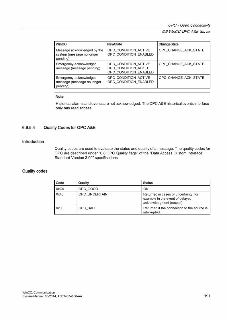
8/20/2019 WinCC Communication en-US en-US
http://slidepdf.com/reader/full/wincc-communication-en-us-en-us 191/527
WinCC NewState ChangeState
Message acknowledged by the
system (message no longerpending)
OPC_CONDITION_ACTIVE
OPC_CONDITION_ENABLED
OPC_CHANGE_ACK_STATE
Emergency-acknowledgedmessage (message pending)
OPC_CONDITION_ACTIVEOPC_CONDITION_ACKEDOPC_CONDITION_ENABLED
OPC_CHANGE_ACK_STATE
Emergency-acknowledgedmessage (message no longerpending)
OPC_CONDITION_ACTIVEOPC_CONDITION_ENABLED
OPC_CHANGE_ACK_STATE
Note
Historical alarms and events are not acknowledged. The OPC A&E historical events interfaceonly has read access.
6.9.5.4 Quality Codes for OPC A&E
Introduction
Quality codes are used to evaluate the status and quality of a message. The quality codes forOPC are described under "6.8 OPC Quality flags" of the "Data Access Custom InterfaceStandard Version 3.00" specifications.
Quality codes
Code Quality Status
0xC0 OPC_GOOD OK
0x40 OPC_UNCERTAIN Returned in cases of uncertainty, forexample in the event of delayedacknowledgment (receipt).
0x00 OPC_BAD Returned if the connection to the source isinterrupted.
OPC - Open Connectivity
6.9 WinCC OPC A&E Server
WinCC: CommunicationSystem Manual, 06/2014, A5E34374800-AA 191
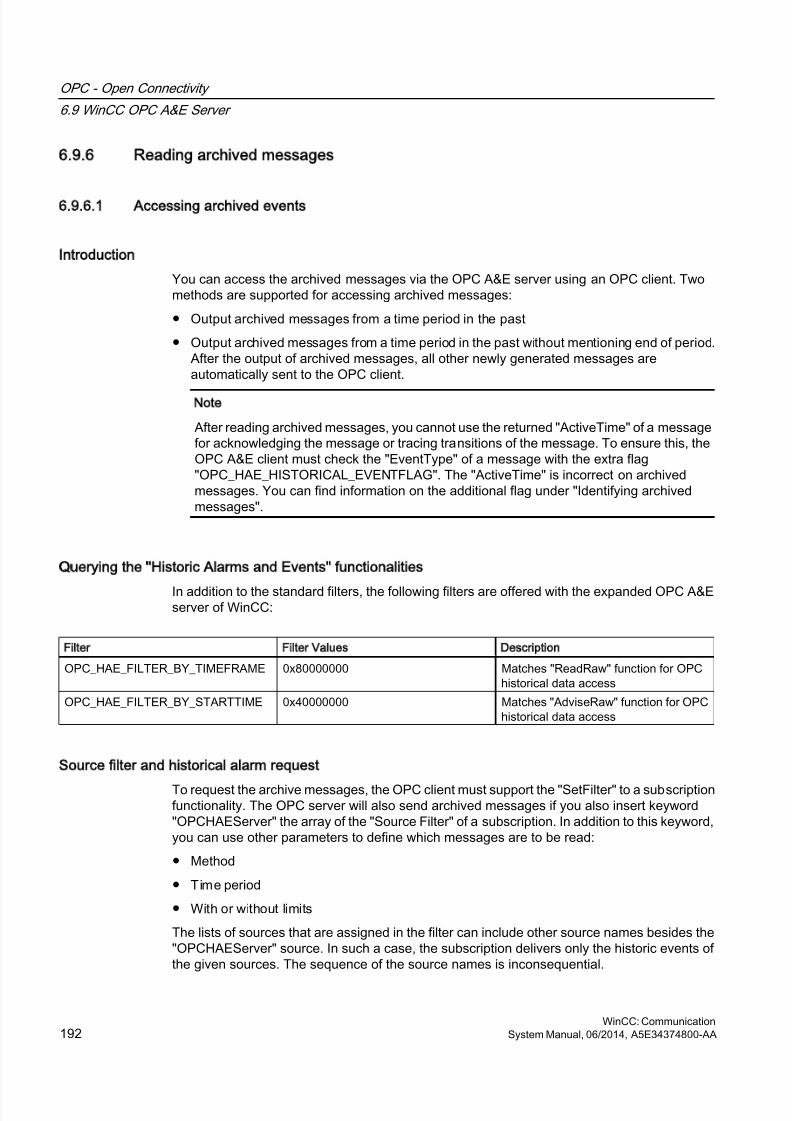
8/20/2019 WinCC Communication en-US en-US
http://slidepdf.com/reader/full/wincc-communication-en-us-en-us 192/527
6.9.6 Reading archived messages
6.9.6.1 Accessing archived events
Introduction
You can access the archived messages via the OPC A&E server using an OPC client. Twomethods are supported for accessing archived messages:
● Output archived messages from a time period in the past
● Output archived messages from a time period in the past without mentioning end of period.After the output of archived messages, all other newly generated messages areautomatically sent to the OPC client.
Note
After reading archived messages, you cannot use the returned "ActiveTime" of a messagefor acknowledging the message or tracing transitions of the message. To ensure this, theOPC A&E client must check the "EventType" of a message with the extra flag"OPC_HAE_HISTORICAL_EVENTFLAG". The "ActiveTime" is incorrect on archivedmessages. You can find information on the additional flag under "Identifying archivedmessages".
Querying the Historic Alarms and Events functionalities
In addition to the standard filters, the following filters are offered with the expanded OPC A&Eserver of WinCC:
Filter Filter Values Description
OPC_HAE_FILTER_BY_TIMEFRAME 0x80000000 Matches "ReadRaw" function for OPChistorical data access
OPC_HAE_FILTER_BY_STARTTIME 0x40000000 Matches "AdviseRaw" function for OPChistorical data access
Source filter and historical alarm request
To request the archive messages, the OPC client must support the "SetFilter" to a subscriptionfunctionality. The OPC server will also send archived messages if you also insert keyword"OPCHAEServer" the array of the "Source Filter" of a subscription. In addition to this keyword,you can use other parameters to define which messages are to be read:
● Method
● Time period
● With or without limits
The lists of sources that are assigned in the filter can include other source names besides the"OPCHAEServer" source. In such a case, the subscription delivers only the historic events ofthe given sources. The sequence of the source names is inconsequential.
OPC - Open Connectivity
6.9 WinCC OPC A&E Server
WinCC: Communication192 System Manual, 06/2014, A5E34374800-AA
8/20/2019 WinCC Communication en-US en-US
http://slidepdf.com/reader/full/wincc-communication-en-us-en-us 193/527
After configuring the source filter, the selected time period can be called up from the client witha "Refresh" call.
6.9.6.2 Syntax for accessing archived messages using OPC
Syntax
OPCHAEServer hMode=(read|advise) htStartTime=szTime[hEndTime=szTime] [bBounds=(TRUE|FALSE)]
Parameter
hMode = [read|advise]
This parameter is required. Defines how the archived messages and events are to be read.
Read: Outputs archived messages and events of a definite period from the past (comparableto ReadRaw in case of OPC Historical Data Access).
The following is an example for setting a filter for reading over the last 30 minutes:
OPCHAEServer hMode=read htStartTime=NOW-30M bBounds=TRUE
Advise: Outputs archived messages and events from a definite period, After receiving allarchived messages, new messages are sent in the same way as in the case of an activesubscription (comparable to AdviseRaw in case of OPC historical data access).
In the following example, the messages of the last 30 minutes are read (subscription must be
active):OPCHAEServer hMode=advise htStartTime=NOW-30M
Note
The following notation is supported for parameters "htStartTime" and "htEndTime":
● Relative notations, for example NOW
● Symbolic values, for example NOW, YEAR, MONTH
● Specification of absolute UTC data/time values according to XML notation:2006-09-01T10:00:00.000Z
Using the symbolic notation corresponds to the syntax from OPC historical data access.
htStartTime =
This parameter is required. Defines the time from when the messages and events are to beread from the archive.
htEndTime =
This parameter is optional. Defines the time up to which the messages and events are to beread from the archive. With "hMode = read", the default setting "NOW" is used.
OPC - Open Connectivity
6.9 WinCC OPC A&E Server
WinCC: CommunicationSystem Manual, 06/2014, A5E34374800-AA 193
8/20/2019 WinCC Communication en-US en-US
http://slidepdf.com/reader/full/wincc-communication-en-us-en-us 194/527
bBounds = [TRUE|FALSE]
This parameter is optional. Defines how messages close to the start and end time are to be
handled. The function is identical to OPC historical data access.bBounds=FALSE:
● The time stamp of the first transferred message >= htStartTime
● The time stamp of the last transferred message >= htEndTime
bBounds=TRUE:
● The time stamp of the first transferred message <= htStartTime
● The time stamp of the last transferred message >= hEndTime
Default setting is FALSE.
6.9.6.3 Read methods for archived messages
Introduction
You can use one of the two read modes to read archived messages:
● Read
● Advise
Read mode
"Read" mode is used to read archived messages from a defined period in the past. Thesequence of read messages is always read from the alarms in chronological sequence inreference to each OS server. By setting the start and end time, you can specify whether thelast message is to be read first or last. If the start time is earlier than the end time, the lastmessage is last in the output.
To use the "read" mode, you need to run the following functions on the subscription:
1. SetFilter
2. Refresh
"SetFilter" during "Refresh" will be rejected. Activating the subscription during "Refresh" doesnot have any effect on refresh.
The historic events continue to be transferred with the Refresh flag.
The newly generated events are transferred according to the standard reaction of an activesubscription:
● Taking into account the set filter values with the exception of "historic" source"OPCHAEServer"
● Without the Refresh flag
The client can therefore distinguish between the received events based on the Refresh flag.An event package never contains historic and new events at the same time.
OPC - Open Connectivity
6.9 WinCC OPC A&E Server
WinCC: Communication194 System Manual, 06/2014, A5E34374800-AA
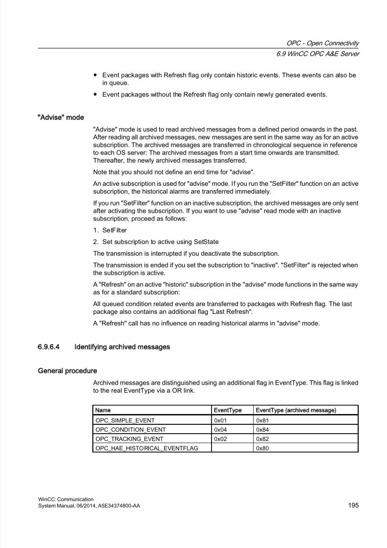
8/20/2019 WinCC Communication en-US en-US
http://slidepdf.com/reader/full/wincc-communication-en-us-en-us 195/527
● Event packages with Refresh flag only contain historic events. These events can also bein queue.
● Event packages without the Refresh flag only contain newly generated events.
Advise mode
"Advise" mode is used to read archived messages from a defined period onwards in the past.After reading all archived messages, new messages are sent in the same way as for an activesubscription. The archived messages are transferred in chronological sequence in referenceto each OS server: The archived messages from a start time onwards are transmitted.Thereafter, the newly archived messages transferred.
Note that you should not define an end time for "advise".
An active subscription is used for "advise" mode. If you run the "SetFilter" function on an active
subscription, the historical alarms are transferred immediately.If you run "SetFilter" function on an inactive subscription, the archived messages are only sentafter activating the subscription. If you want to use "advise" read mode with an inactivesubscription, proceed as follows:
1. SetFilter
2. Set subscription to active using SetState
The transmission is interrupted if you deactivate the subscription.
The transmission is ended if you set the subscription to "inactive". "SetFilter" is rejected whenthe subscription is active.
A "Refresh" on an active "historic" subscription in the "advise" mode functions in the same wayas for a standard subscription:
All queued condition related events are transferred to packages with Refresh flag. The lastpackage also contains an additional flag "Last Refresh".
A "Refresh" call has no influence on reading historical alarms in "advise" mode.
6.9.6.4 Identifying archived messages
General procedure
Archived messages are distinguished using an additional flag in EventType. This flag is linkedto the real EventType via a OR link.
Name EventType EventType (archived message)
OPC_SIMPLE_EVENT 0x01 0x81
OPC_CONDITION_EVENT 0x04 0x84
OPC_TRACKING_EVENT 0x02 0x82
OPC_HAE_HISTORICAL_EVENTFLAG 0x80
OPC - Open Connectivity
6.9 WinCC OPC A&E Server
WinCC: CommunicationSystem Manual, 06/2014, A5E34374800-AA 195
8/20/2019 WinCC Communication en-US en-US
http://slidepdf.com/reader/full/wincc-communication-en-us-en-us 196/527
Examples
Example 1
The following source filter is used to output archived messages and events of the last 30minutes in "read" mode. The oldest message for each OS server is output as the first one. Thelow limit value is also sent.
OPCHAEServer hMode=read htStartTime=NOW-30M bBounds=TRUE
Example 2
The following source filter is used to output archived events on September 1, 2006 from 10:00to 12:00 hours in "read" mode. The newest message for each OS server is output as the firstone. The limits for this time period are also sent.
OPCHAEServer hMode=read htStartTime=2006-09-01T12:00:00.000Z
htEndTime=2006-09-01T10:00:00.000Z bBounds=TRUE
Example 3
The following source filter is used to output archived messages and events of the last 30minutes in "advise" mode. After reading the archived messages, newly generated messagesare sent in the same way as for an active subscription.
OPCHAEServer hmode=advise htStartTime=NOW-30M
OPC - Open Connectivity
6.9 WinCC OPC A&E Server
WinCC: Communication196 System Manual, 06/2014, A5E34374800-AA
8/20/2019 WinCC Communication en-US en-US
http://slidepdf.com/reader/full/wincc-communication-en-us-en-us 197/527
6.10 WinCC OPC UA Server
6.10.1 Principle of operation the WinCC OPC UA Server
How it works
The WinCC OPC UA Server provides the following values:
● Process values
● Values from tag archives
● WinCC messages
The WinCC OPC UA server is installed as Windows service and started automatically. TheWinCC OPC UA server supports only the "UA-TCP UA-SC UA Binary" communication profile.The used port number is adjustable.
Supported specifications
OPC Unified Architecture is a specification for the transmission of process values, archive dataand messages. The WinCC OPC UA server supports OPC UA Specification 1.02. Foradditional information about supported UA functions, refer to "Supported OPC UA servicesand profiles (Page 204)".
Installation
After WinCC is installed, the WinCC OPC UA server can be used immediately without the needfor any further configuration.The WinCC OPC UA server can be used on a WinCC server or a WinCC client.
URL of the WinCC OPC UA server
You access the WinCC OPC UA server via the following URL:
● "opc.tcp://[HostName]:[Port]"
Parameter Description
HostName Placeholder for the computer name. Is used automatically
Port Port number. The default setting is "4862".
Discovery Server
The "Discovery Server" is available by the OPC foundation. The "Discovery Server" is bydefault installed on the HMI device as Windows service.
On the "Discovery Server" via OPC UA server UA clients information is available that isregistered on the "Discovery Server".
OPC - Open Connectivity
6.10 WinCC OPC UA Server
WinCC: CommunicationSystem Manual, 06/2014, A5E34374800-AA 197
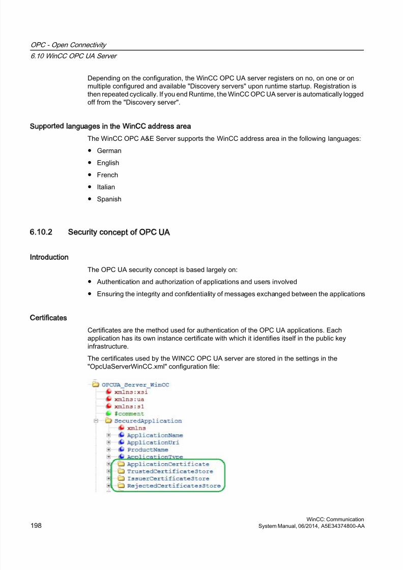
8/20/2019 WinCC Communication en-US en-US
http://slidepdf.com/reader/full/wincc-communication-en-us-en-us 198/527
Depending on the configuration, the WinCC OPC UA server registers on no, on one or onmultiple configured and available "Discovery servers" upon runtime startup. Registration isthen repeated cyclically. If you end Runtime, the WinCC OPC UA server is automatically logged
off from the "Discovery server".
Supported languages in the WinCC address area
The WinCC OPC A&E Server supports the WinCC address area in the following languages:
● German
● English
● French
● Italian
● Spanish
6.10.2 Security concept of OPC UA
Introduction
The OPC UA security concept is based largely on:
● Authentication and authorization of applications and users involved
● Ensuring the integrity and confidentiality of messages exchanged between the applications
Certificates
Certificates are the method used for authentication of the OPC UA applications. Eachapplication has its own instance certificate with which it identifies itself in the public keyinfrastructure.
The certificates used by the WINCC OPC UA server are stored in the settings in the"OpcUaServerWinCC.xml" configuration file:
OPC - Open Connectivity
6.10 WinCC OPC UA Server
WinCC: Communication198 System Manual, 06/2014, A5E34374800-AA
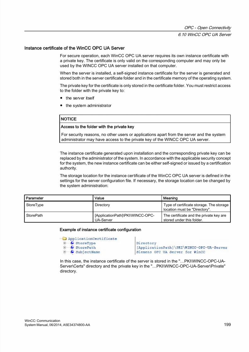
8/20/2019 WinCC Communication en-US en-US
http://slidepdf.com/reader/full/wincc-communication-en-us-en-us 199/527
Instance certificate of the WinCC OPC UA Server
For secure operation, each WinCC OPC UA server requires its own instance certificate with
a private key. The certificate is only valid on the corresponding computer and may only beused by the WINCC OPC UA server installed on that computer.
When the server is installed, a self-signed instance certificate for the server is generated andstored both in the server certificate folder and in the certificate memory of the operating system.
The private key for the certificate is only stored in the certificate folder. You must restrict accessto the folder with the private key to:
● the server itself
● the system administrator
NOTICE
Access to the folder with the private key
For security reasons, no other users or applications apart from the server and the systemadministrator may have access to the private key of the WINCC OPC UA server.
The instance certificate generated upon installation and the corresponding private key can bereplaced by the administrator of the system. In accordance with the applicable security conceptfor the system, the new instance certificate can be either self-signed or issued by a certificationauthority.
The storage location for the instance certificate of the WinCC OPC UA server is defined in thesettings for the server configuration file. If necessary, the storage location can be changed by
the system administration:
Parameter Value Meaning
StoreType Directory Type of certificate storage. The storagelocation must be "Directory".
StorePath [ApplicationPath]\PKI\WINCC-OPC-UA-Server
The certificate and the private key arestored under this folder.
Example of instance certificate configuration
In this case, the instance certificate of the server is stored in the "…PKI\WINCC-OPC-UA-Server\Certs" directory and the private key in the "…PKI\WINCC-OPC-UA-Server\Private"directory.
OPC - Open Connectivity
6.10 WinCC OPC UA Server
WinCC: CommunicationSystem Manual, 06/2014, A5E34374800-AA 199
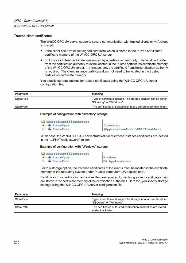
8/20/2019 WinCC Communication en-US en-US
http://slidepdf.com/reader/full/wincc-communication-en-us-en-us 200/527
Trusted client certificates
The WinCC OPC UA server supports secure communication with trusted clients only. A client
is trusted:● If the client has a valid self-signed certificate which is stored in the trusted certificates
certificate memory of the WinCC OPC UA server
● or if the valid client certificate was issued by a certification authority. The valid certificatefrom the certification authority must be located in the trusted certificates certificate memoryof the WinCC OPC UA server. In this case, only the certificate from the certification authorityis required. The client instance certificate does not need to be located in the trustedcertificates certificate memory.
You specify storage settings for trusted certificates using the WINCC OPC UA serverconfiguration file:
Parameter Meaning
StoreType Type of certificate storage. The storage location can be either"Directory" or "Windows".
StorePath The certificates of trusted clients are stored under this folder.
Example of configuration with Directory storage
In this case, the WINCC OPC UA server trusts all clients whose instance certificates are locatedin the "…PKI\TrustList\Certs" folder.
Example of configuration with Windows storage
For this storage option, the instance certificates of the clients must be located in the certificatememory of the operating system under "<Local computer>\UA applications".
Certificates from certification authorities that are required for verifying a client certificate chainare stored in the certificate memory of the certification authorities. Here too, you specify storage
settings using the WINCC OPC UA server configuration file:
Parameter Meaning
StoreType Type of certificate storage. The storage location can be either"Directory" or "Windows".
StorePath The certificates of trusted certification authorities are storedunder this folder.
OPC - Open Connectivity
6.10 WinCC OPC UA Server
WinCC: Communication200 System Manual, 06/2014, A5E34374800-AA
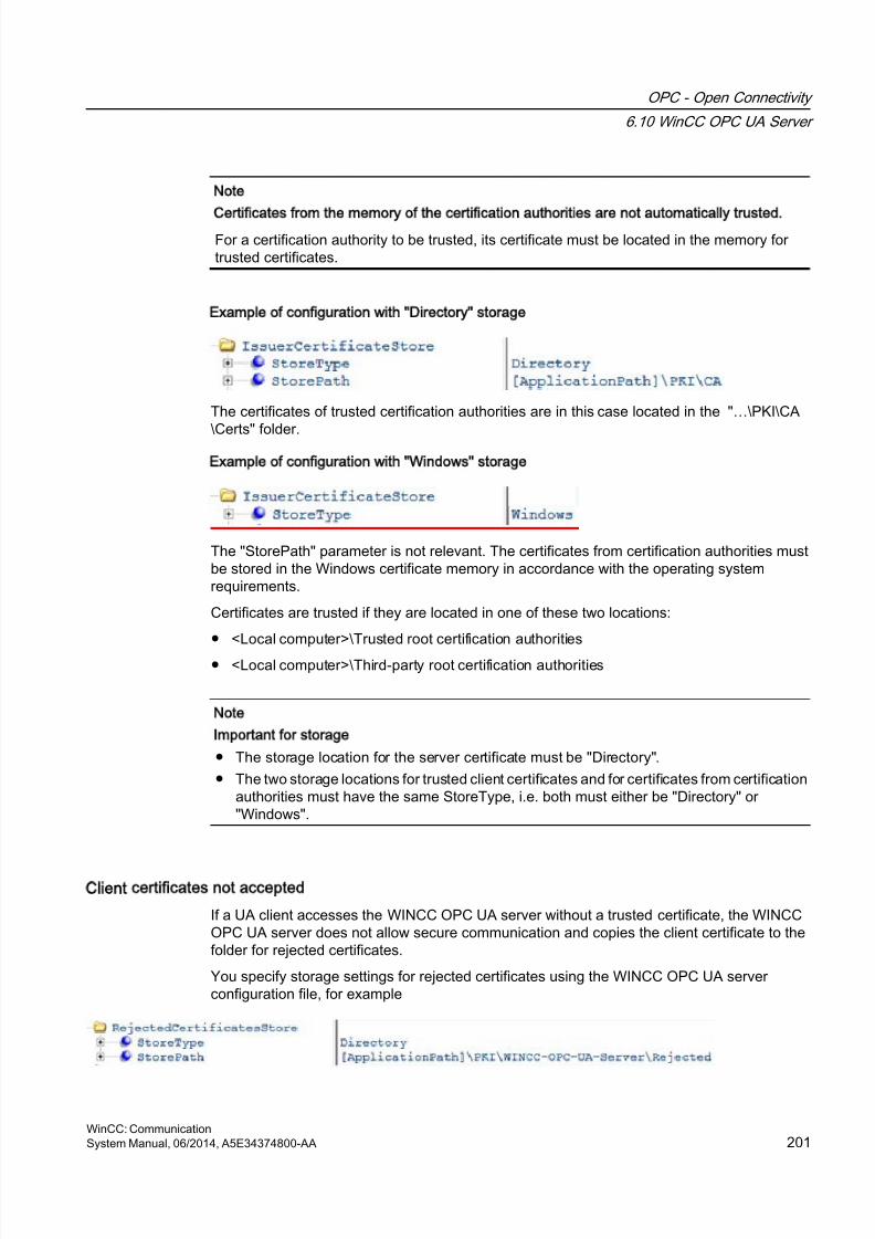
8/20/2019 WinCC Communication en-US en-US
http://slidepdf.com/reader/full/wincc-communication-en-us-en-us 201/527
Note
Certificates from the memory of the certification authorities are not automatically trusted.
For a certification authority to be trusted, its certificate must be located in the memory fortrusted certificates.
Example of configuration with Directory storage
The certificates of trusted certification authorities are in this case located in the "…\PKI\CA
\Certs" folder.
Example of configuration with Windows storage
The "StorePath" parameter is not relevant. The certificates from certification authorities mustbe stored in the Windows certificate memory in accordance with the operating systemrequirements.
Certificates are trusted if they are located in one of these two locations:
● <Local computer>\Trusted root certification authorities
● <Local computer>\Third-party root certification authorities
Note
Important for storage
● The storage location for the server certificate must be "Directory".
● The two storage locations for trusted client certificates and for certificates from certificationauthorities must have the same StoreType, i.e. both must either be "Directory" or"Windows".
Client certificates not accepted
If a UA client accesses the WINCC OPC UA server without a trusted certificate, the WINCCOPC UA server does not allow secure communication and copies the client certificate to thefolder for rejected certificates.
You specify storage settings for rejected certificates using the WINCC OPC UA serverconfiguration file, for example
OPC - Open Connectivity
6.10 WinCC OPC UA Server
WinCC: CommunicationSystem Manual, 06/2014, A5E34374800-AA 201
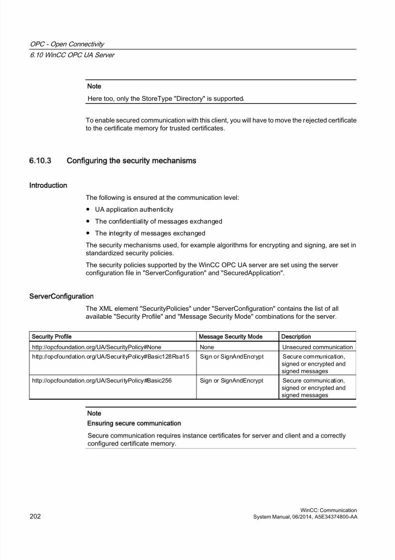
8/20/2019 WinCC Communication en-US en-US
http://slidepdf.com/reader/full/wincc-communication-en-us-en-us 202/527
Note
Here too, only the StoreType "Directory" is supported.
To enable secured communication with this client, you will have to move the rejected certificateto the certificate memory for trusted certificates.
6.10.3 Configuring the security mechanisms
Introduction
The following is ensured at the communication level:
● UA application authenticity
● The confidentiality of messages exchanged
● The integrity of messages exchanged
The security mechanisms used, for example algorithms for encrypting and signing, are set instandardized security policies.
The security policies supported by the WinCC OPC UA server are set using the serverconfiguration file in "ServerConfiguration" and "SecuredApplication".
ServerConfiguration
The XML element "SecurityPolicies" under "ServerConfiguration" contains the list of allavailable "Security Profile" and "Message Security Mode" combinations for the server.
Security Profile Message Security Mode Description
http://opcfoundation.org/UA/SecurityPolicy#None None Unsecured communication
http://opcfoundation.org/UA/SecurityPolicy#Basic128Rsa15 Sign or SignAndEncrypt Secure communication,signed or encrypted andsigned messages
http://opcfoundation.org/UA/SecurityPolicy#Basic256 Sign or SignAndEncrypt Secure communication,signed or encrypted andsigned messages
Note
Ensuring secure communication
Secure communication requires instance certificates for server and client and a correctlyconfigured certificate memory.
OPC - Open Connectivity
6.10 WinCC OPC UA Server
WinCC: Communication202 System Manual, 06/2014, A5E34374800-AA
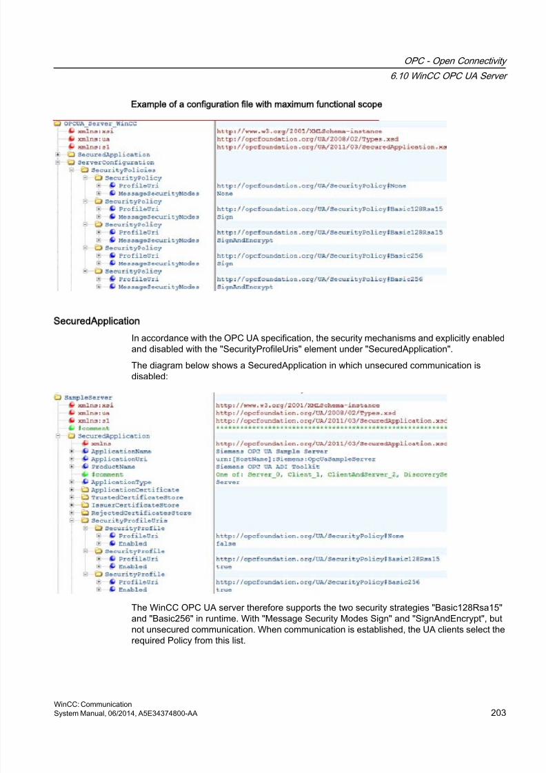
8/20/2019 WinCC Communication en-US en-US
http://slidepdf.com/reader/full/wincc-communication-en-us-en-us 203/527
Example of a configuration file with maximum functional scope
SecuredApplication
In accordance with the OPC UA specification, the security mechanisms and explicitly enabledand disabled with the "SecurityProfileUris" element under "SecuredApplication".
The diagram below shows a SecuredApplication in which unsecured communication isdisabled:
The WinCC OPC UA server therefore supports the two security strategies "Basic128Rsa15"and "Basic256" in runtime. With "Message Security Modes Sign" and "SignAndEncrypt", butnot unsecured communication. When communication is established, the UA clients select therequired Policy from this list.
OPC - Open Connectivity
6.10 WinCC OPC UA Server
WinCC: CommunicationSystem Manual, 06/2014, A5E34374800-AA 203
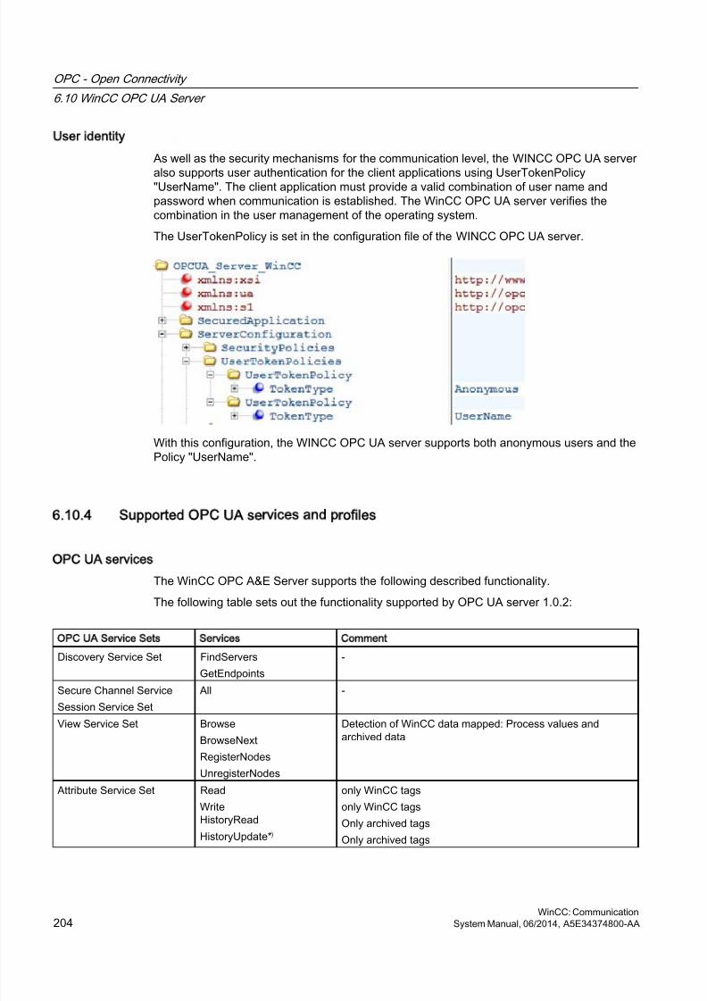
8/20/2019 WinCC Communication en-US en-US
http://slidepdf.com/reader/full/wincc-communication-en-us-en-us 204/527
User identity
As well as the security mechanisms for the communication level, the WINCC OPC UA server
also supports user authentication for the client applications using UserTokenPolicy"UserName". The client application must provide a valid combination of user name andpassword when communication is established. The WinCC OPC UA server verifies thecombination in the user management of the operating system.
The UserTokenPolicy is set in the configuration file of the WINCC OPC UA server.
With this configuration, the WINCC OPC UA server supports both anonymous users and thePolicy "UserName".
6.10.4 Supported OPC UA services and profiles
OPC UA services
The WinCC OPC A&E Server supports the following described functionality.
The following table sets out the functionality supported by OPC UA server 1.0.2:
OPC UA Service Sets Services Comment
Discovery Service Set FindServers
GetEndpoints
-
Secure Channel Service
Session Service Set
All -
View Service Set Browse
BrowseNext
RegisterNodes
UnregisterNodes
Detection of WinCC data mapped: Process values andarchived data
Attribute Service Set Read
WriteHistoryRead
HistoryUpdate*)
only WinCC tags
only WinCC tags
Only archived tags
Only archived tags
OPC - Open Connectivity
6.10 WinCC OPC UA Server
WinCC: Communication204 System Manual, 06/2014, A5E34374800-AA
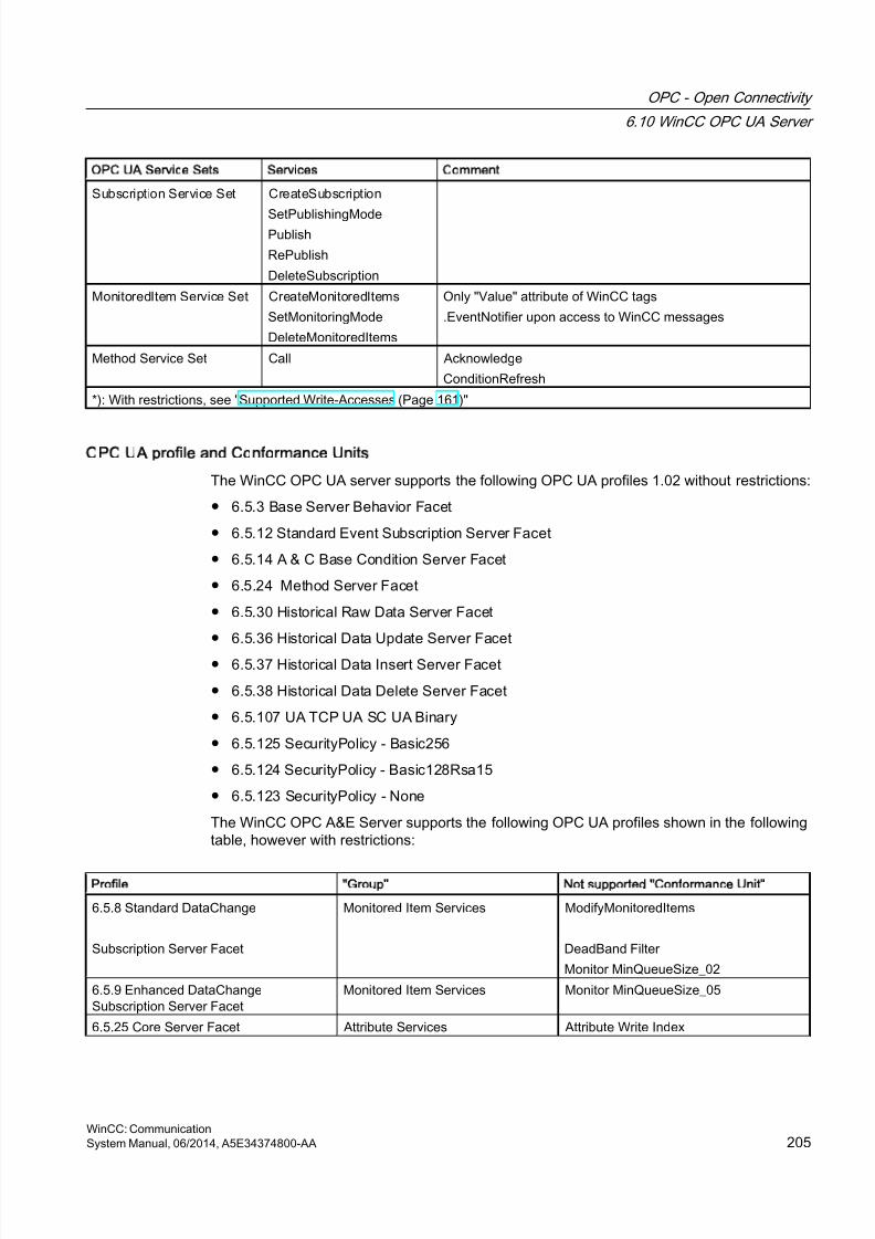
8/20/2019 WinCC Communication en-US en-US
http://slidepdf.com/reader/full/wincc-communication-en-us-en-us 205/527
OPC UA Service Sets Services Comment
Subscription Service Set CreateSubscription
SetPublishingModePublish
RePublish
DeleteSubscription
MonitoredItem Service Set CreateMonitoredItems
SetMonitoringMode
DeleteMonitoredItems
Only "Value" attribute of WinCC tags
.EventNotifier upon access to WinCC messages
Method Service Set Call Acknowledge
ConditionRefresh
*): With restrictions, see "Supported Write-Accesses (Page 161)"
OPC UA profile and Conformance Units
The WinCC OPC UA server supports the following OPC UA profiles 1.02 without restrictions:
● 6.5.3 Base Server Behavior Facet
● 6.5.12 Standard Event Subscription Server Facet
● 6.5.14 A & C Base Condition Server Facet
● 6.5.24 Method Server Facet
● 6.5.30 Historical Raw Data Server Facet
● 6.5.36 Historical Data Update Server Facet
● 6.5.37 Historical Data Insert Server Facet
● 6.5.38 Historical Data Delete Server Facet
● 6.5.107 UA TCP UA SC UA Binary
● 6.5.125 SecurityPolicy - Basic256
● 6.5.124 SecurityPolicy - Basic128Rsa15
● 6.5.123 SecurityPolicy - None
The WinCC OPC A&E Server supports the following OPC UA profiles shown in the followingtable, however with restrictions:
Profile Group Not supported Conformance Unit
6.5.8 Standard DataChange
Subscription Server Facet
Monitored Item Services ModifyMonitoredItems
DeadBand Filter
Monitor MinQueueSize_02
6.5.9 Enhanced DataChangeSubscription Server Facet
Monitored Item Services Monitor MinQueueSize_05
6.5.25 Core Server Facet Attribute Services Attribute Write Index
OPC - Open Connectivity
6.10 WinCC OPC UA Server
WinCC: CommunicationSystem Manual, 06/2014, A5E34374800-AA 205
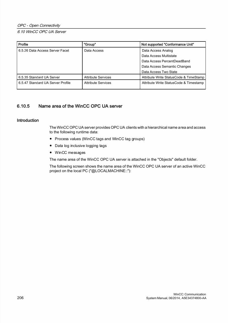
8/20/2019 WinCC Communication en-US en-US
http://slidepdf.com/reader/full/wincc-communication-en-us-en-us 206/527
Profile Group Not supported Conformance Unit
6.5.26 Data Access Server Facet Data Access Data Access Analog
Data Access MultistateData Access PercentDeadBand
Data Access Semantic Changes
Data Access Two State
6.5.35 Standard UA Server Attribute Services Attribute Write StatusCode & TimeStamp
6.5.47 Standard UA Server Profile Attribute Services Attribute Write StatusCode & Timestamp
6.10.5 Name area of the WinCC OPC UA server
Introduction
The WinCC OPC UA server provides OPC UA clients with a hierarchical name area and accessto the following runtime data:
● Process values (WinCC tags and WinCC tag groups)
● Data log inclusive logging tags
● WinCC messages
The name area of the WinCC OPC UA server is attached in the "Objects" default folder.
The following screen shows the name area of the WinCC OPC UA server of an active WinCC
project on the local PC ("@LOCALMACHINE::"):
OPC - Open Connectivity
6.10 WinCC OPC UA Server
WinCC: Communication206 System Manual, 06/2014, A5E34374800-AA
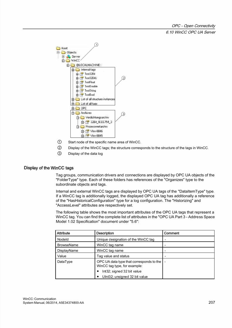
8/20/2019 WinCC Communication en-US en-US
http://slidepdf.com/reader/full/wincc-communication-en-us-en-us 207/527
1
2
3
① Start node of the specific name area of WinCC.
② Display of the WinCC tags; the structure corresponds to the structure of the tags in WinCC.
③ Display of the data log
Display of the WinCC tags
Tag groups, communication drivers and connections are displayed by OPC UA objects of the"FolderType" type. Each of these folders has references of the "Organizes" type to thesubordinate objects and tags.
Internal and external WinCC tags are displayed by OPC UA tags of the "DataItemType" type.If a WinCC tag is additionally logged, the displayed OPC UA tag has additionally a referenceof the "HasHistoricalConfiguration" type for a log configuration. The "Historizing" and"AccessLevel" attributes are respectively set.
The following table shows the most important attributes of the OPC UA tags that represent aWinCC tag. You can find the complete list of attributes in the "OPC UA Part 3 - Address SpaceModel 1.02 Specification" document under "5.6":
Attribute Description Comment
NodeId Unique designation of the WinCC tag -
BrowseName WinCC tag name -
DisplayName WinCC tag name -
Value Tag value and status -
DataType OPC UA data type that corresponds to theWinCC tag type, for example:
● Int32; signed 32 bit value
● UInt32; unsigned 32 bit value
-
OPC - Open Connectivity
6.10 WinCC OPC UA Server
WinCC: CommunicationSystem Manual, 06/2014, A5E34374800-AA 207
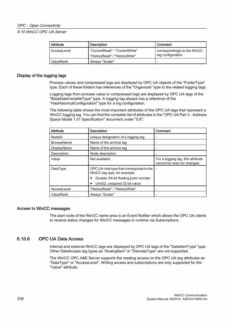
8/20/2019 WinCC Communication en-US en-US
http://slidepdf.com/reader/full/wincc-communication-en-us-en-us 208/527
Attribute Description Comment
AccessLevel "CurrentRead" / "CurrentWrite"
"HistoryRead" / "HistoryWrite"
correspondingly to the WinCC
tag configurationValueRank Always "Scalar" -
Display of the logging tags
Process values and compressed logs are displayed by OPC UA objects of the "FolderType"type. Each of these folders has references of the "Organizes" type to the related logging tags.
Logging tags from process value or compressed logs are displayed by OPC UA tags of the"BaseDateVariableType" type. A logging tag always has a reference of the"HasHistoricalConfiguration" type for a log configuration.
The following table shows the most important attributes of the OPC UA tags that represent a
WinCC logging tag. You can find the complete list of attributes in the "OPC UA Part 3 - AddressSpace Model 1.01 Specification" document under "5.6":
Attribute Description Comment
NodeId Unique designation of a logging tag -
BrowseName Name of the archive tag -
DisplayName Name of the archive tag -
Description Node description -
Value Not available For a logging tag, this attributecannot be read nor changed.
DataType OPC UA data type that corresponds to theWinCC tag type, for example:
● Double; 64-bit floating point number
● UInt32; unsigned 32 bit value
-
AccessLevel "HistoryRead" / "HistoryWrite" -
ValueRank Always "Scalar" -
Access to WinCC messages
The start node of the WinCC name area is an Event Notifier which allows the OPC UA clientsto receive status changes for WinCC messages in runtime via Subscriptions .
6.10.6 OPC UA Data Access
Internal and external WinCC tags are displayed by OPC UA tags of the "DataItemType" type.Other DataAccess tag types as "AnalogItem" or "DiscreteType" are not supported.
The WinCC OPC A&E Server supports the reading access on the OPC UA tag attributes as"DataType" or "AccessLevel". Writing access and subscriptions are only supported for the"Value" attribute.
OPC - Open Connectivity
6.10 WinCC OPC UA Server
WinCC: Communication208 System Manual, 06/2014, A5E34374800-AA
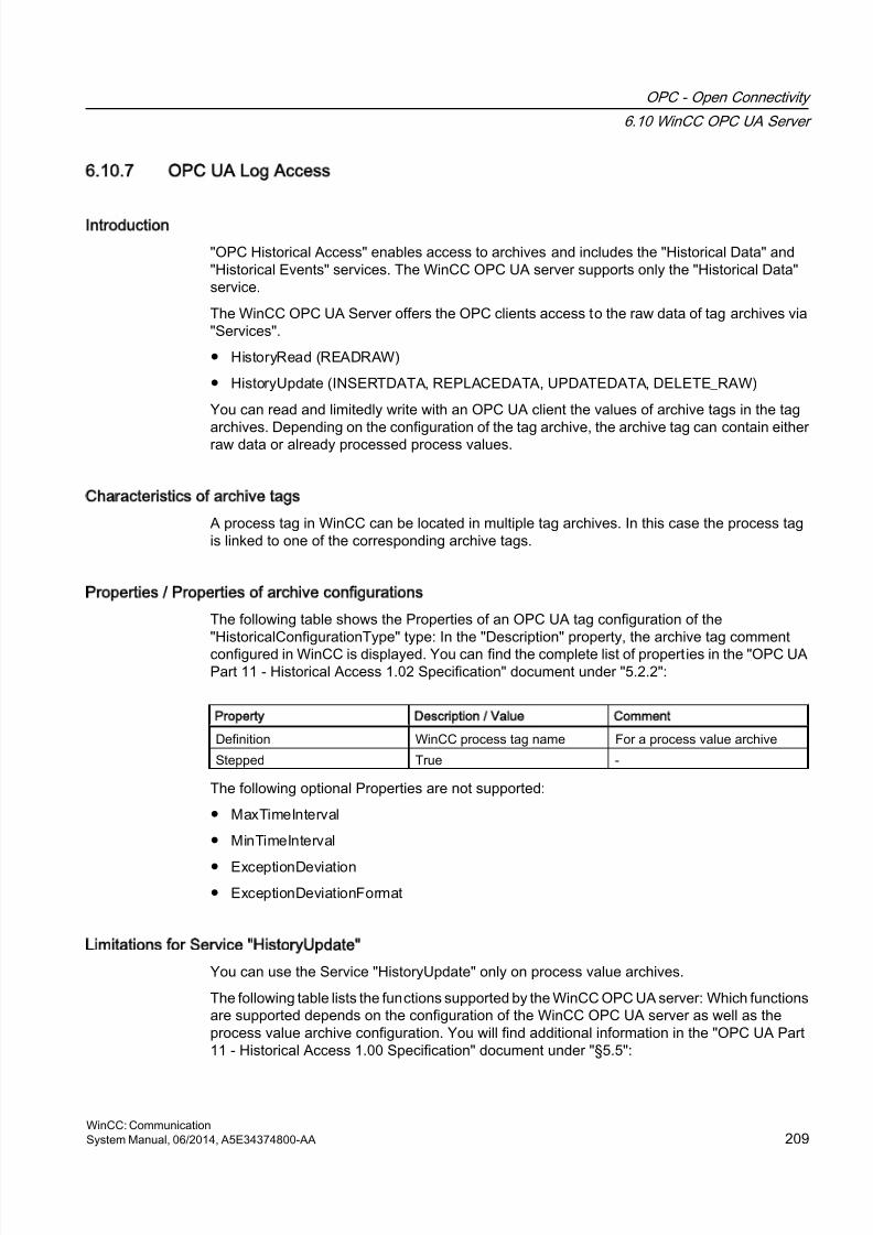
8/20/2019 WinCC Communication en-US en-US
http://slidepdf.com/reader/full/wincc-communication-en-us-en-us 209/527
6.10.7 OPC UA Log Access
Introduction
"OPC Historical Access" enables access to archives and includes the "Historical Data" and"Historical Events" services. The WinCC OPC UA server supports only the "Historical Data"service.
The WinCC OPC UA Server offers the OPC clients access to the raw data of tag archives via"Services".
● HistoryRead (READRAW)
● HistoryUpdate (INSERTDATA, REPLACEDATA, UPDATEDATA, DELETE_RAW)
You can read and limitedly write with an OPC UA client the values of archive tags in the tag
archives. Depending on the configuration of the tag archive, the archive tag can contain eitherraw data or already processed process values.
Characteristics of archive tags
A process tag in WinCC can be located in multiple tag archives. In this case the process tagis linked to one of the corresponding archive tags.
Properties / Properties of archive configurations
The following table shows the Properties of an OPC UA tag configuration of the"HistoricalConfigurationType" type: In the "Description" property, the archive tag comment
configured in WinCC is displayed. You can find the complete list of properties in the "OPC UAPart 11 - Historical Access 1.02 Specification" document under "5.2.2":
Property Description / Value Comment
Definition WinCC process tag name For a process value archive
Stepped True -
The following optional Properties are not supported:
● MaxTimeInterval
● MinTimeInterval
● ExceptionDeviation● ExceptionDeviationFormat
Limitations for Service HistoryUpdate
You can use the Service "HistoryUpdate" only on process value archives.
The following table lists the functions supported by the WinCC OPC UA server: Which functionsare supported depends on the configuration of the WinCC OPC UA server as well as theprocess value archive configuration. You will find additional information in the "OPC UA Part11 - Historical Access 1.00 Specification" document under "§5.5":
OPC - Open Connectivity
6.10 WinCC OPC UA Server
WinCC: CommunicationSystem Manual, 06/2014, A5E34374800-AA 209
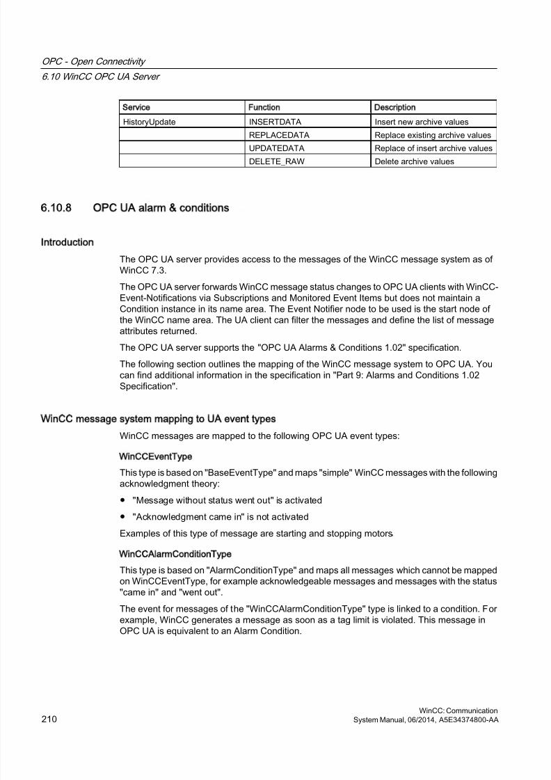
8/20/2019 WinCC Communication en-US en-US
http://slidepdf.com/reader/full/wincc-communication-en-us-en-us 210/527
Service Function Description
HistoryUpdate INSERTDATA Insert new archive values
REPLACEDATA Replace existing archive values UPDATEDATA Replace of insert archive values
DELETE_RAW Delete archive values
6.10.8 OPC UA alarm & conditions
Introduction
The OPC UA server provides access to the messages of the WinCC message system as of
WinCC 7.3.The OPC UA server forwards WinCC message status changes to OPC UA clients with WinCC-Event-Notifications via Subscriptions and Monitored Event Items but does not maintain aCondition instance in its name area. The Event Notifier node to be used is the start node ofthe WinCC name area. The UA client can filter the messages and define the list of messageattributes returned.
The OPC UA server supports the "OPC UA Alarms & Conditions 1.02" specification.
The following section outlines the mapping of the WinCC message system to OPC UA. Youcan find additional information in the specification in "Part 9: Alarms and Conditions 1.02Specification".
WinCC message system mapping to UA event types
WinCC messages are mapped to the following OPC UA event types:
WinCCEventType
This type is based on "BaseEventType" and maps "simple" WinCC messages with the followingacknowledgment theory:
● "Message without status went out" is activated
● "Acknowledgment came in" is not activated
Examples of this type of message are starting and stopping motors.
WinCCAlarmConditionType
This type is based on "AlarmConditionType" and maps all messages which cannot be mappedon WinCCEventType, for example acknowledgeable messages and messages with the status"came in" and "went out".
The event for messages of the "WinCCAlarmConditionType" type is linked to a condition. Forexample, WinCC generates a message as soon as a tag limit is violated. This message inOPC UA is equivalent to an Alarm Condition.
OPC - Open Connectivity
6.10 WinCC OPC UA Server
WinCC: Communication210 System Manual, 06/2014, A5E34374800-AA
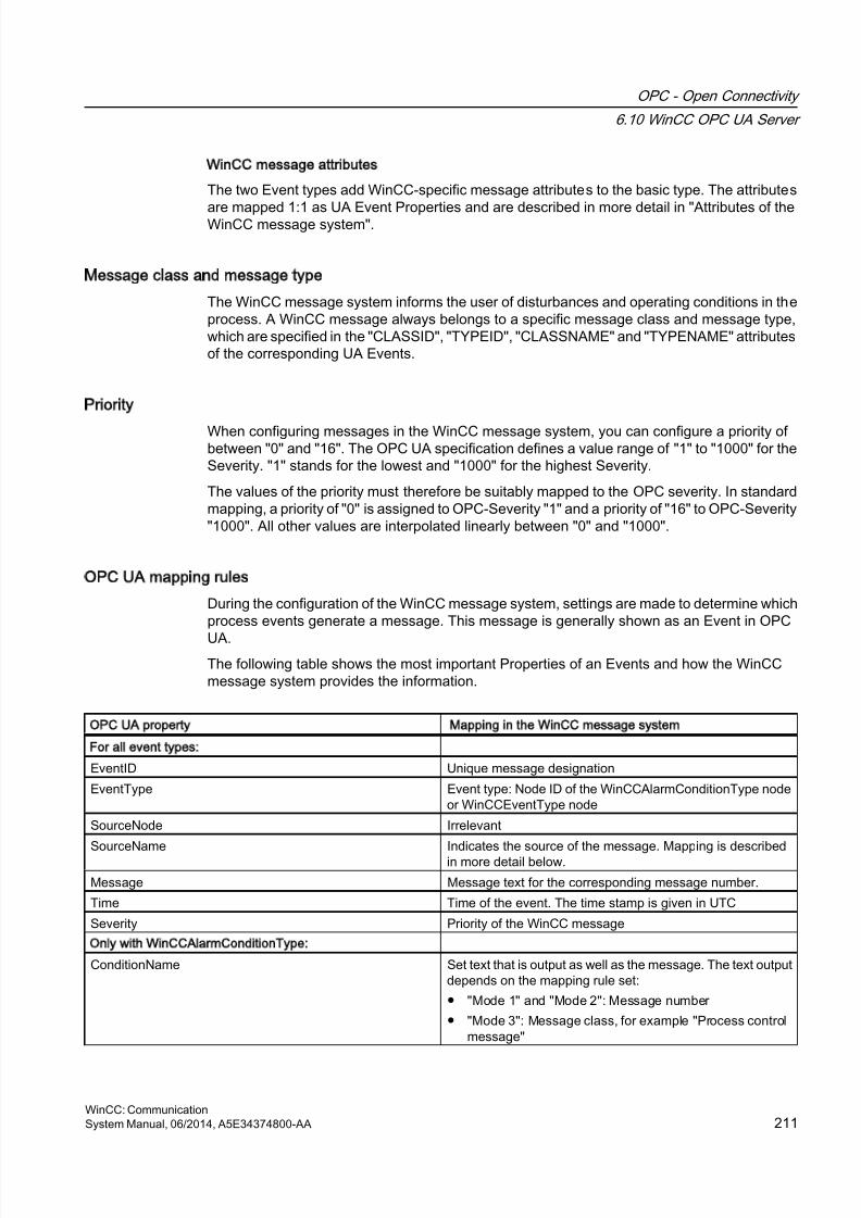
8/20/2019 WinCC Communication en-US en-US
http://slidepdf.com/reader/full/wincc-communication-en-us-en-us 211/527
WinCC message attributes
The two Event types add WinCC-specific message attributes to the basic type. The attributes
are mapped 1:1 as UA Event Properties and are described in more detail in "Attributes of theWinCC message system".
Message class and message type
The WinCC message system informs the user of disturbances and operating conditions in theprocess. A WinCC message always belongs to a specific message class and message type,which are specified in the "CLASSID", "TYPEID", "CLASSNAME" and "TYPENAME" attributesof the corresponding UA Events.
Priority
When configuring messages in the WinCC message system, you can configure a priority ofbetween "0" and "16". The OPC UA specification defines a value range of "1" to "1000" for theSeverity. "1" stands for the lowest and "1000" for the highest Severity.
The values of the priority must therefore be suitably mapped to the OPC severity. In standardmapping, a priority of "0" is assigned to OPC-Severity "1" and a priority of "16" to OPC-Severity"1000". All other values are interpolated linearly between "0" and "1000".
OPC UA mapping rules
During the configuration of the WinCC message system, settings are made to determine whichprocess events generate a message. This message is generally shown as an Event in OPC
UA.The following table shows the most important Properties of an Events and how the WinCCmessage system provides the information.
OPC UA property Mapping in the WinCC message system
For all event types:
EventID Unique message designation
EventType Event type: Node ID of the WinCCAlarmConditionType nodeor WinCCEventType node
SourceNode Irrelevant
SourceName Indicates the source of the message. Mapping is describedin more detail below.
Message Message text for the corresponding message number.
Time Time of the event. The time stamp is given in UTC
Severity Priority of the WinCC message
Only with WinCCAlarmConditionType:
ConditionName Set text that is output as well as the message. The text outputdepends on the mapping rule set:
● "Mode 1" and "Mode 2": Message number
● "Mode 3": Message class, for example "Process controlmessage"
OPC - Open Connectivity
6.10 WinCC OPC UA Server
WinCC: CommunicationSystem Manual, 06/2014, A5E34374800-AA 211

8/20/2019 WinCC Communication en-US en-US
http://slidepdf.com/reader/full/wincc-communication-en-us-en-us 212/527
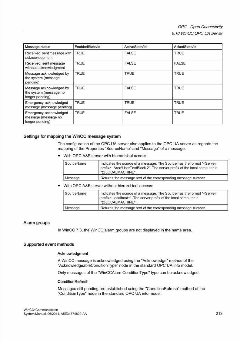
8/20/2019 WinCC Communication en-US en-US
http://slidepdf.com/reader/full/wincc-communication-en-us-en-us 213/527
Message status EnabledState/Id ActiveState/Id AckedState/Id
Received, sent message with
acknowledgment
TRUE FALSE TRUE
Received, sent messagewithout acknowledgment
TRUE FALSE FALSE
Message acknowledged bythe system (messagepending)
TRUE TRUE TRUE
Message acknowledged bythe system (message nolonger pending)
TRUE FALSE TRUE
Emergency-acknowledgedmessage (message pending)
TRUE TRUE TRUE
Emergency-acknowledged
message (message nolonger pending)
TRUE FALSE TRUE
Settings for mapping the WinCC message system
The configuration of the OPC UA server also applies to the OPC UA server as regards themapping of the Properties "SourceName" and "Message" of a message.
● With OPC A&E server with hierarchical access:
SourceName Indicates the source of a message. The Source has the format "<Serverprefix>::Area\UserTextBlock 2". The server prefix of the local computer is"@LOCALMACHINE".
Message Returns the message text of the corresponding message number
● With OPC A&E server without hierarchical access:
SourceName Indicates the source of a message. The Source has the format "<Serverprefix>::localhost::". The server prefix of the local computer is"@LOCALMACHINE".
Message Returns the message text of the corresponding message number
Alarm groups
In WinCC 7.3, the WinCC alarm groups are not displayed in the name area.
Supported event methods
Acknowledgment
A WinCC message is acknowledged using the "Acknowledge" method of the"AcknowledgeableConditionType" node in the standard OPC UA info model.
Only messages of the "WinCCAlarmConditionType" type can be acknowledged.
ConditionRefresh
Messages still pending are established using the "ConditionRefresh" method of the"ConditionType" node in the standard OPC UA info model.
OPC - Open Connectivity
6.10 WinCC OPC UA Server
WinCC: CommunicationSystem Manual, 06/2014, A5E34374800-AA 213
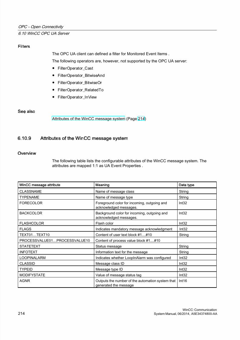
8/20/2019 WinCC Communication en-US en-US
http://slidepdf.com/reader/full/wincc-communication-en-us-en-us 214/527
Filters
The OPC UA client can defined a filter for Monitored Event Items .
The following operators are, however, not supported by the OPC UA server:
● FilterOperator_Cast
● FilterOperator_BitwiseAnd
● FilterOperator_BitwiseOr
● FilterOperator_RelatedTo
● FilterOperator_InView
See also
Attributes of the WinCC message system (Page 214)
6.10.9 Attributes of the WinCC message system
Overview
The following table lists the configurable attributes of the WinCC message system. Theattributes are mapped 1:1 as UA Event Properties .
WinCC message attribute Meaning Data type
CLASSNAME Name of message class String
TYPENAME Name of message type String
FORECOLOR Foreground color for incoming, outgoing andacknowledged messages.
Int32
BACKCOLOR Background color for incoming, outgoing andacknowledged messages.
Int32
FLASHCOLOR Flash color Int32
FLAGS Indicates mandatory message acknowledgment Int32
TEXT01…TEXT10 Content of user text block #1....#10 String
PROCESSVALUE01…PROCESSVALUE10 Content of process value block #1....#10
STATETEXT Status message String
INFOTEXT Information text for the message String
LOOPINALARM Indicates whether LoopInAlarm was configured Int32
CLASSID Message class ID Int32
TYPEID Message type ID Int32
MODIFYSTATE Value of message status tag Int32
AGNR Outputs the number of the automation system thatgenerated the message
Int16
OPC - Open Connectivity
6.10 WinCC OPC UA Server
WinCC: Communication214 System Manual, 06/2014, A5E34374800-AA
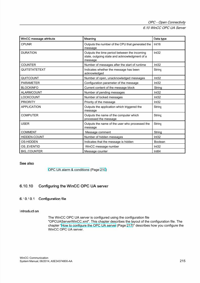
8/20/2019 WinCC Communication en-US en-US
http://slidepdf.com/reader/full/wincc-communication-en-us-en-us 215/527
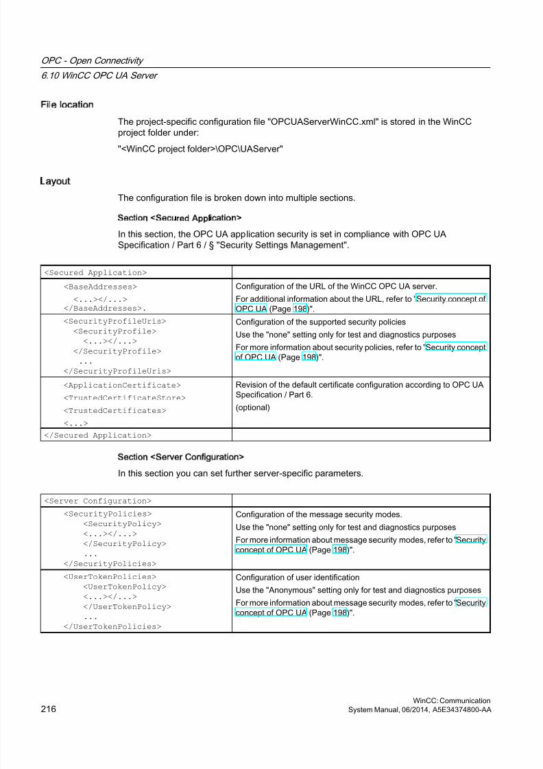
8/20/2019 WinCC Communication en-US en-US
http://slidepdf.com/reader/full/wincc-communication-en-us-en-us 216/527
File location
The project-specific configuration file "OPCUAServerWinCC.xml" is stored in the WinCC
project folder under:"<WinCC project folder>\OPC\UAServer"
Layout
The configuration file is broken down into multiple sections.
Section <Secured Application>
In this section, the OPC UA application security is set in compliance with OPC UASpecification / Part 6 / § "Security Settings Management".
<Secured Application>
<BaseAddresses>
<...></...> </BaseAddresses>.
Configuration of the URL of the WinCC OPC UA server.
For additional information about the URL, refer to "Security concept ofOPC UA (Page 198)".
<SecurityProfileUris>
<SecurityProfile>
<...></...>
</SecurityProfile>
...
</SecurityProfileUris>
Configuration of the supported security policies
Use the "none" setting only for test and diagnostics purposes
For more information about security policies, refer to "Security conceptof OPC UA (Page 198)".
<ApplicationCertificate>
<TrustedCertificateStore>
<TrustedCertificates>
<...>
Revision of the default certificate configuration according to OPC UASpecification / Part 6.
(optional)
</Secured Application>
Section <Server Configuration>
In this section you can set further server-specific parameters.
<Server Configuration>
<SecurityPolicies>
<SecurityPolicy>
<...></...>
</SecurityPolicy>
...
</SecurityPolicies>
Configuration of the message security modes.
Use the "none" setting only for test and diagnostics purposes
For more information about message security modes, refer to "Securityconcept of OPC UA (Page 198)".
<UserTokenPolicies>
<UserTokenPolicy>
<...></...>
</UserTokenPolicy>
...
</UserTokenPolicies>
Configuration of user identification
Use the "Anonymous" setting only for test and diagnostics purposes
For more information about message security modes, refer to "Securityconcept of OPC UA (Page 198)".
OPC - Open Connectivity
6.10 WinCC OPC UA Server
WinCC: Communication216 System Manual, 06/2014, A5E34374800-AA
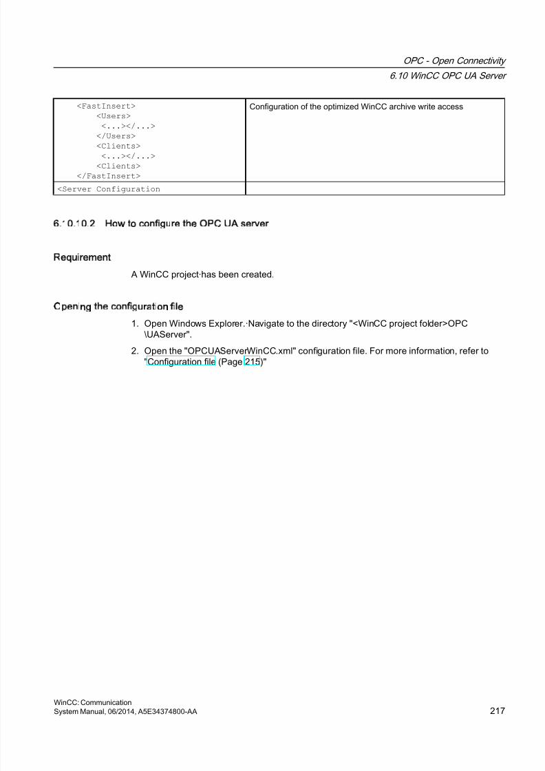
8/20/2019 WinCC Communication en-US en-US
http://slidepdf.com/reader/full/wincc-communication-en-us-en-us 217/527
<FastInsert>
<Users>
<...></...>
</Users> <Clients>
<...></...>
<Clients>
</FastInsert>
Configuration of the optimized WinCC archive write access
<Server Configuration
6.10.10.2 How to configure the OPC UA server
Requirement
A WinCC project·has been created.
Opening the configuration file
1. Open Windows Explorer.·Navigate to the directory "<WinCC project folder>OPC\UAServer".
2. Open the "OPCUAServerWinCC.xml" configuration file. For more information, refer to"Configuration file (Page 215)"
OPC - Open Connectivity
6.10 WinCC OPC UA Server
WinCC: CommunicationSystem Manual, 06/2014, A5E34374800-AA 217
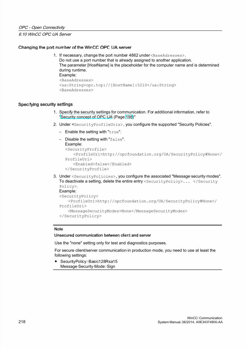
8/20/2019 WinCC Communication en-US en-US
http://slidepdf.com/reader/full/wincc-communication-en-us-en-us 218/527
Changing the port number of the WinCC OPC UA server
1. If necessary, change the port number 4862 under <BaseAdresses>.
Do not use a port number that is already assigned to another application.The parameter [HostName] is the placeholder for the computer name and is determinedduring runtime.Example:<BaseAdresses><ua:String>opc.tcp://[HostName]:5210</ua:String><BaseAdresses>
Specifying security settings
1. Specify the security settings for communication.·For additional information, refer to"Security concept of OPC UA (Page 198)"
2. Under <SecurityProfileUris> , you configure the supported "Security Policies".
– Enable the setting with "true".
– Disable the setting with "false".Example:<SecurityProfile> <ProfileUri>http://opcfoundation.org/UA/SecurityPolicy#None</ProfileUri> <Enabled>false</Enabled></SecurityProfile>
3. Under <SecurityPolicies> , you configure the associated "Message·security·modes".To deactivate a setting, delete the entire entry
<SecurityPolicy>... </SecurityPolicy>.Example:<SecurityPolicy> <ProfileUri>http://opcfoundation.org/UA/SecurityPolicy#None</ProfileUri> <MessageSecurityModes>None</MessageSecurityModes></SecurityPolicy>
Note
Unsecured communication between client and server
Use the "none" setting only for test and diagnostics purposes.For secure client/server communication·in production mode, you need to use at least thefollowing settings:
● SecurityPolicy:·Basic128Rsa15Message·Security·Mode:·Sign
OPC - Open Connectivity
6.10 WinCC OPC UA Server
WinCC: Communication218 System Manual, 06/2014, A5E34374800-AA
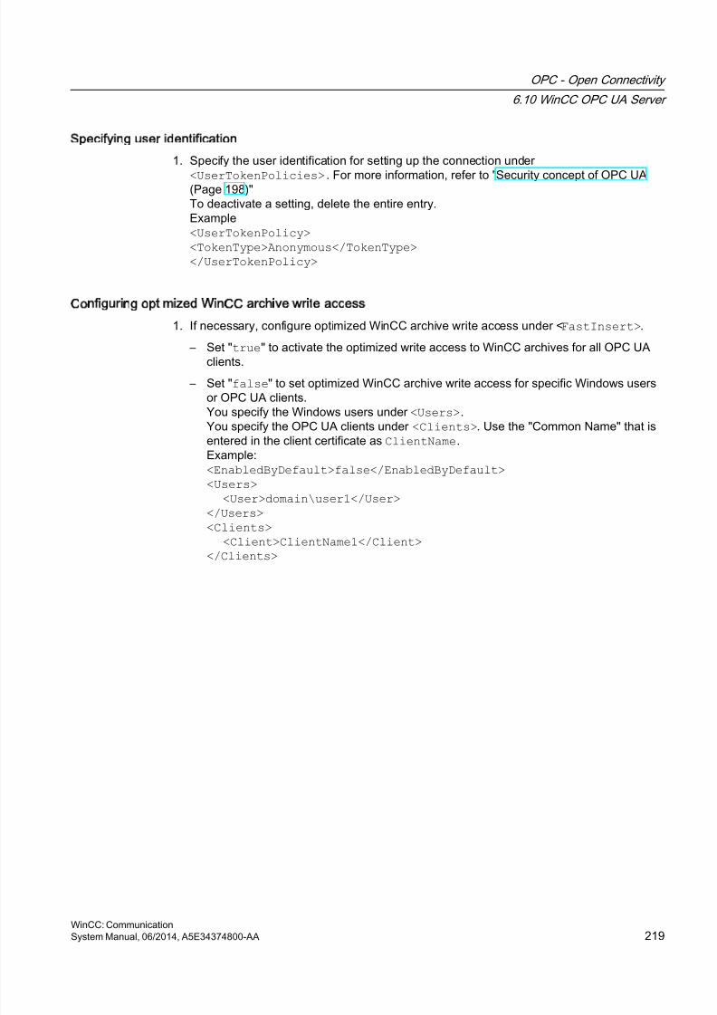
8/20/2019 WinCC Communication en-US en-US
http://slidepdf.com/reader/full/wincc-communication-en-us-en-us 219/527
Specifying user identification
1. Specify the user identification for setting up the connection under
<UserTokenPolicies> . For more information, refer to "Security concept of OPC UA (Page 198)"To deactivate a setting, delete the entire entry.Example<UserTokenPolicy><TokenType>Anonymous</TokenType></UserTokenPolicy>
Configuring optimized WinCC archive write access
1. If necessary, configure optimized WinCC archive write access under <FastInsert>.
– Set "true" to activate the optimized write access to WinCC archives for all OPC UAclients.
– Set "false" to set optimized WinCC archive write access for specific Windows usersor OPC UA clients.You specify the Windows users under <Users>.You specify the OPC UA clients under <Clients>. Use the "Common Name" that isentered in the client certificate as ClientName.Example:<EnabledByDefault>false</EnabledByDefault><Users> <User>domain\user1</User></Users>
<Clients> <Client>ClientName1</Client></Clients>
OPC - Open Connectivity
6.10 WinCC OPC UA Server
WinCC: CommunicationSystem Manual, 06/2014, A5E34374800-AA 219
8/20/2019 WinCC Communication en-US en-US
http://slidepdf.com/reader/full/wincc-communication-en-us-en-us 220/527
6.11 Trace
Introduction
The "Trace" function can be used to log tag values and function calls for purposes of testingand error analysis.
The entries are stored in a trace file. The trace shows the step-by-step progress of theestablishment of the connection, thus making it easier to identify the source of a connectionproblem.
Settings
Trace output must be set in the registry of the operating system. For more information, refer
to the SIMATIC Customer Support.
OPC - Open Connectivity
6.11 Trace
WinCC: Communication220 System Manual, 06/2014, A5E34374800-AA

8/20/2019 WinCC Communication en-US en-US
http://slidepdf.com/reader/full/wincc-communication-en-us-en-us 221/527
PROFIBUS FMS
7
7.1 WinCC channel PROFIBUS FMS
Introduction
The "PROFIBUS FMS" communication driver makes the connection between a WinCC stationand automation systems such as S5 or S7.
This chapter describes
● how to configure data transfer with the "PROFIBUS FMS" channel
● how to configure a connection and a tag.
Channel Unit
The communication driver has a channel unit. This provides the following capability:
● Channel unit PROFIBUS FMS for SIMATIC NET PROFIBUS (communication module DP5613).
Note
The configuration of the logical connection can take place in configuration mode as well
as in runtime. Both methods are explained.Only WinCC can request data from the connected AS with the "PROFIBUS FMS" channel.Sending from the AS is not possible.
WinCC: CommunicationSystem Manual, 06/2014, A5E34374800-AA 221

8/20/2019 WinCC Communication en-US en-US
http://slidepdf.com/reader/full/wincc-communication-en-us-en-us 222/527
7.2 Data type of the tags
Introduction
Define the required tags for a logical connection. From the WinCC viewpoint, you can accessthe following data types:
● Binary tag
● Unsigned 8-bit value
● Signed 8-bit value
● Unsigned 16-bit value
● Signed 16-bit value
● Unsigned 32-bit value● Signed 32-bit value
● Floating-point number 32-bit IEEE 754
● Text tag, 8-bit character set.
● Raw data type
PROFIBUS FMS
7.2 Data type of the tags
WinCC: Communication222 System Manual, 06/2014, A5E34374800-AA
8/20/2019 WinCC Communication en-US en-US
http://slidepdf.com/reader/full/wincc-communication-en-us-en-us 223/527
7.3 Configuring the Channel
7.3.1 Configuring a connection
7.3.1.1 Configuring a connection
Introduction
The automation system must be connected to PROFIBUS with a suitable communicationprocessor. The PROFIBUS FMS protocol must be supported by the hardware / software.
In automation systems S5-115U, S5-135U and S5-155U, communication processor CP 5431FMS is used for instance.
in WinCC system, the communication module CP 5613 and software SIMATIC NET must beinstalled.
When configuring the connection, the following situations are handled differently:
● Configuring in configuration mode
● Configuring in Runtime
7.3.1.2 Configuring the connection in configuration mode
Procedure
1. In the navigation area of the tag management, select the channel unit "PROFIBUS FMS"in the tree of the communication driver "PROFIBUS FMS".
2. Select the entry "New Connection" in the shortcut menu of the channel unit.
3. Enter the name of the connection.
PROFIBUS FMS
7.3 Configuring the Channel
WinCC: CommunicationSystem Manual, 06/2014, A5E34374800-AA 223

8/20/2019 WinCC Communication en-US en-US
http://slidepdf.com/reader/full/wincc-communication-en-us-en-us 224/527
4. Select the entry "Connection parameters" from the shortcut menu of the connection.A dialog with the connection name as its title is displayed
5. Enter the name or the index of the logical connection in the "Name/Index" field.The Name/Index of the logical connection must be configured in the local communicationrelationship list (CRL).
6. If access authorization has been assigned for the logical connection, please select the "WithAuthorization" field.
PROFIBUS FMS
7.3 Configuring the Channel
WinCC: Communication224 System Manual, 06/2014, A5E34374800-AA
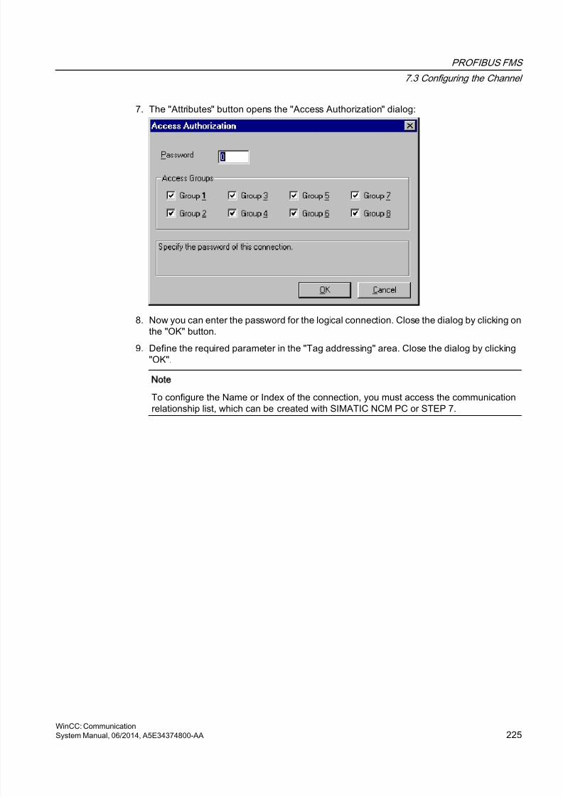
8/20/2019 WinCC Communication en-US en-US
http://slidepdf.com/reader/full/wincc-communication-en-us-en-us 225/527
7. The "Attributes" button opens the "Access Authorization" dialog:
8. Now you can enter the password for the logical connection. Close the dialog by clicking onthe "OK" button.
9. Define the required parameter in the "Tag addressing" area. Close the dialog by clicking"OK".
Note
To configure the Name or Index of the connection, you must access the communicationrelationship list, which can be created with SIMATIC NCM PC or STEP 7.
PROFIBUS FMS
7.3 Configuring the Channel
WinCC: CommunicationSystem Manual, 06/2014, A5E34374800-AA 225
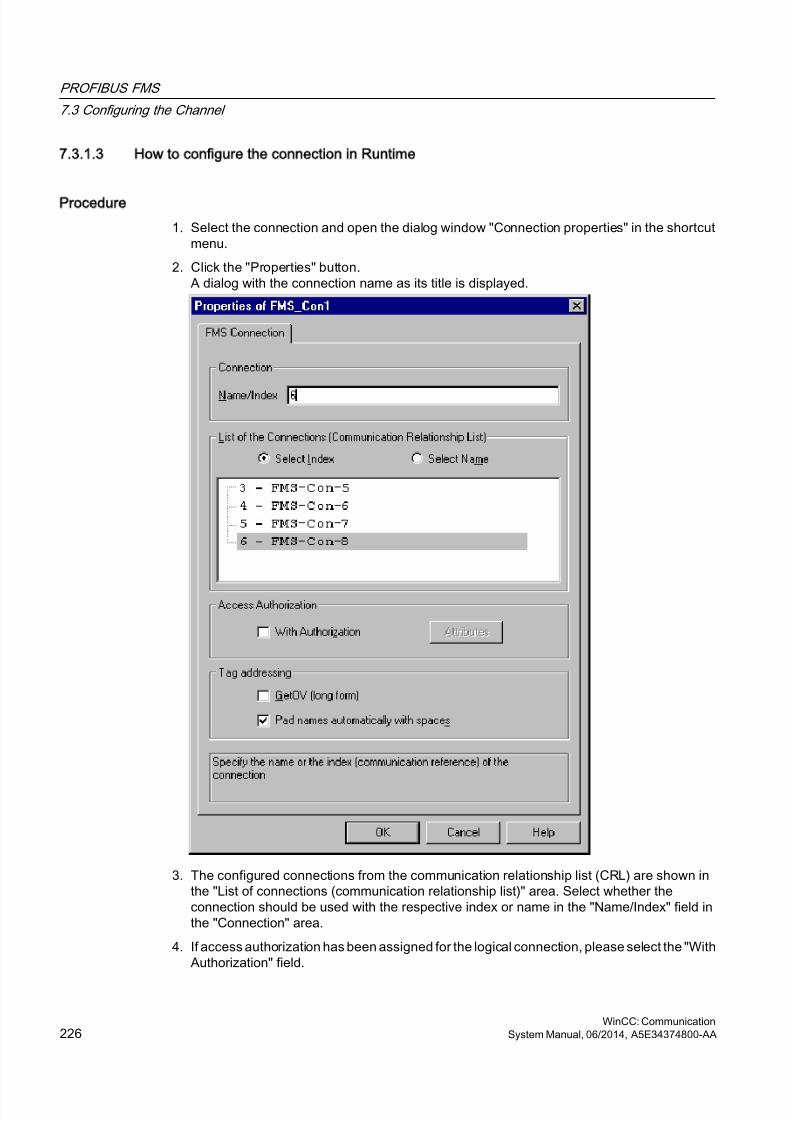
8/20/2019 WinCC Communication en-US en-US
http://slidepdf.com/reader/full/wincc-communication-en-us-en-us 226/527
7.3.1.3 How to configure the connection in Runtime
Procedure
1. Select the connection and open the dialog window "Connection properties" in the shortcutmenu.
2. Click the "Properties" button.A dialog with the connection name as its title is displayed.
3. The configured connections from the communication relationship list (CRL) are shown inthe "List of connections (communication relationship list)" area. Select whether theconnection should be used with the respective index or name in the "Name/Index" field inthe "Connection" area.
4. If access authorization has been assigned for the logical connection, please select the "WithAuthorization" field.
PROFIBUS FMS
7.3 Configuring the Channel
WinCC: Communication226 System Manual, 06/2014, A5E34374800-AA
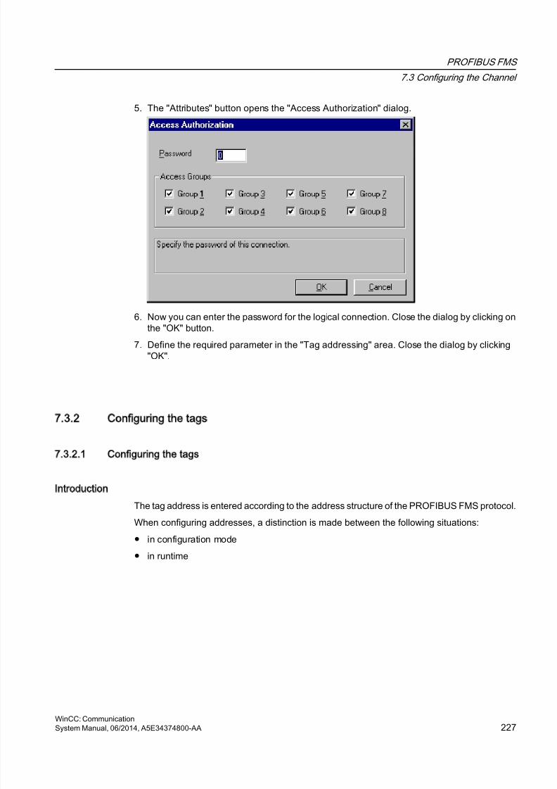
8/20/2019 WinCC Communication en-US en-US
http://slidepdf.com/reader/full/wincc-communication-en-us-en-us 227/527
5. The "Attributes" button opens the "Access Authorization" dialog.
6. Now you can enter the password for the logical connection. Close the dialog by clicking onthe "OK" button.
7. Define the required parameter in the "Tag addressing" area. Close the dialog by clicking"OK".
7.3.2 Configuring the tags
7.3.2.1 Configuring the tags
Introduction
The tag address is entered according to the address structure of the PROFIBUS FMS protocol.
When configuring addresses, a distinction is made between the following situations:
● in configuration mode
● in runtime
PROFIBUS FMS
7.3 Configuring the Channel
WinCC: CommunicationSystem Manual, 06/2014, A5E34374800-AA 227
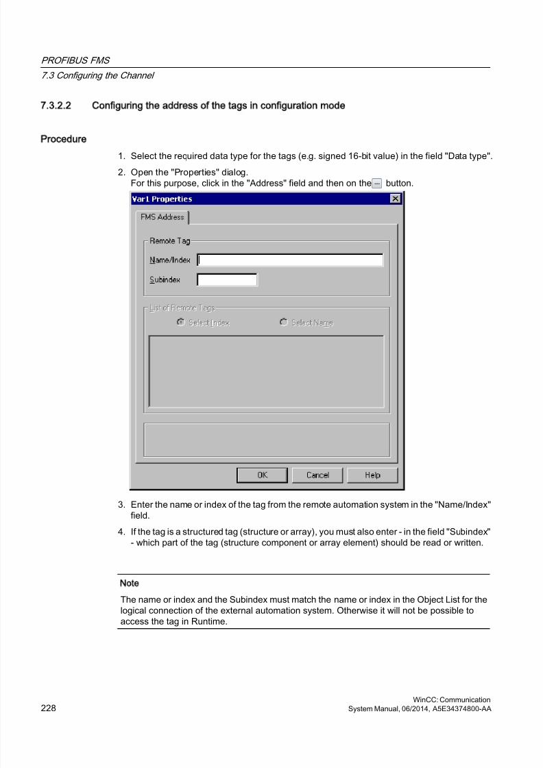
8/20/2019 WinCC Communication en-US en-US
http://slidepdf.com/reader/full/wincc-communication-en-us-en-us 228/527
7.3.2.2 Configuring the address of the tags in configuration mode
Procedure
1. Select the required data type for the tags (e.g. signed 16-bit value) in the field "Data type".
2. Open the "Properties" dialog.For this purpose, click in the "Address" field and then on the button.
3. Enter the name or index of the tag from the remote automation system in the "Name/Index"field.
4. If the tag is a structured tag (structure or array), you must also enter - in the field "Subindex"- which part of the tag (structure component or array element) should be read or written.
Note
The name or index and the Subindex must match the name or index in the Object List for thelogical connection of the external automation system. Otherwise it will not be possible toaccess the tag in Runtime.
PROFIBUS FMS
7.3 Configuring the Channel
WinCC: Communication228 System Manual, 06/2014, A5E34374800-AA
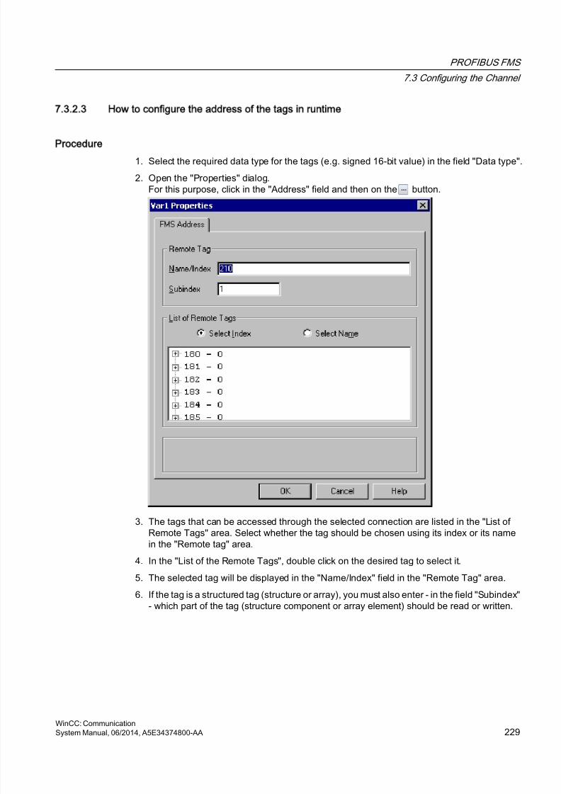
8/20/2019 WinCC Communication en-US en-US
http://slidepdf.com/reader/full/wincc-communication-en-us-en-us 229/527
7.3.2.3 How to configure the address of the tags in runtime
Procedure
1. Select the required data type for the tags (e.g. signed 16-bit value) in the field "Data type".
2. Open the "Properties" dialog.For this purpose, click in the "Address" field and then on the button.
3. The tags that can be accessed through the selected connection are listed in the "List ofRemote Tags" area. Select whether the tag should be chosen using its index or its namein the "Remote tag" area.
4. In the "List of the Remote Tags", double click on the desired tag to select it.
5. The selected tag will be displayed in the "Name/Index" field in the "Remote Tag" area.
6. If the tag is a structured tag (structure or array), you must also enter - in the field "Subindex"- which part of the tag (structure component or array element) should be read or written.
PROFIBUS FMS
7.3 Configuring the Channel
WinCC: CommunicationSystem Manual, 06/2014, A5E34374800-AA 229

8/20/2019 WinCC Communication en-US en-US
http://slidepdf.com/reader/full/wincc-communication-en-us-en-us 230/527

8/20/2019 WinCC Communication en-US en-US
http://slidepdf.com/reader/full/wincc-communication-en-us-en-us 231/527
S5 Ethernet Layer 4
8
8.1 WinCC Channel SIMATIC S5 Ethernet Layer 4
Introduction
The communication driver is used e.g. to connect automation systems SIMATIC S5-115U/H,SIMATIC S5-135U and SIMATIC S5-155U/H with the ISO transport protocol or the TCP/IPprotocol.
Depending on the communication protocol that is used, the following communication partners
will be used.
Communication protocol WinCC side SIMATIC S5 side
ISO transport protocol CP1612 (3Com-compatible)CP1613CP1623
CP1430 TF
TCP/IP (conforming with RFC1006) CP1612 (3Com-compatible)CP1613CP1623
CP1430 TCP
When using this channel, no local database is required.
Channel units
The communication driver has two channel units "CP1413-x" which can operate a maximumof two CP 1612, CP1613 or CP1623. The functionality of the channel unit is identical. Theydiffer only in the logical device names of the two CPs. CP1623 is identical to CP1613, but isoperated via PCI Express.
Communication can be established via the TCP/IP protocol with a CP1612, CP1613 or CP1623using the third channel unit "TCP/IP".
The logical device name can be changed in the system parameters of a channel unit. Here, itis also possible to set the parameters for the protocol used.
The following application capabilities exist:
● Channel unit "S5-Transport (CP 1413-1)" for the communication modules for SIMATICIndustrial Ethernet (CP 1612/1613/1623).
● Channel unit "S5-Transport (CP 1413-2)" for the communication modules for SIMATICIndustrial Ethernet (CP 1612/1613/1623).
● Channel unit "S5-Transport (TCP/IP)" for the communication modules for SIMATICIndustrial Ethernet (CP 1612/1613/1623).
WinCC: CommunicationSystem Manual, 06/2014, A5E34374800-AA 231
8/20/2019 WinCC Communication en-US en-US
http://slidepdf.com/reader/full/wincc-communication-en-us-en-us 232/527
8.2 Data type of the tags
Introduction
Define the required tags for a logical connection. From the WinCC viewpoint, you can accessthe following data types:
● Binary tag
● Unsigned 8-bit value
● Signed 8-bit value
● Unsigned 16-bit value
● Signed 16-bit value
● Unsigned 32-bit value● Signed 32-bit value
● Floating-point number 32-bit IEEE 754
● Text tag, 8-bit character set
● Raw data type
S5 Ethernet Layer 4
8.2 Data type of the tags
WinCC: Communication232 System Manual, 06/2014, A5E34374800-AA
8/20/2019 WinCC Communication en-US en-US
http://slidepdf.com/reader/full/wincc-communication-en-us-en-us 233/527
8.3 Configuring the Channel
8.3.1 Configuring the channel SIMATIC S5 Ethernet Layer 4
Introduction
The following steps are required for configuring the channel "SIMATIC S5 Ethernet Layer 4".
1. Configuring the connection
2. Configuring the tags
3. System parameter configuration
8.3.2 How to configure the connection
Introduction
The connection parameters are almost identical for all protocols used. In the following example,communication is described using the ISO transport protocol with a channel unit "CP1413-x".
When implementing the TCP/IP protocol, the IP address of the AS is entered instead of the
Ethernet address. The IP address consists of four numerical values, separated by dots. Thenumerical values must be within the range of 0-255.
For a logical connection, WinCC establishes one connection in the transport layer for reading("READ function" area) and one for writing ("WRITE function" area). The address parametersfor both functions are defined in the dialog. Only if both connections are established is thelogical connection also indicated as being "established".
Allocations for the READ function
WinCC side SIMATIC S5 side
FETCH-Active(Request "READ-Active") READ-Passive(Request "READ-Passive")
FETCH-Passive(Request "WRITE-Passive")
WRITE-Active(Request "WRITE-Active")
S5 Ethernet Layer 4
8.3 Configuring the Channel
WinCC: CommunicationSystem Manual, 06/2014, A5E34374800-AA 233
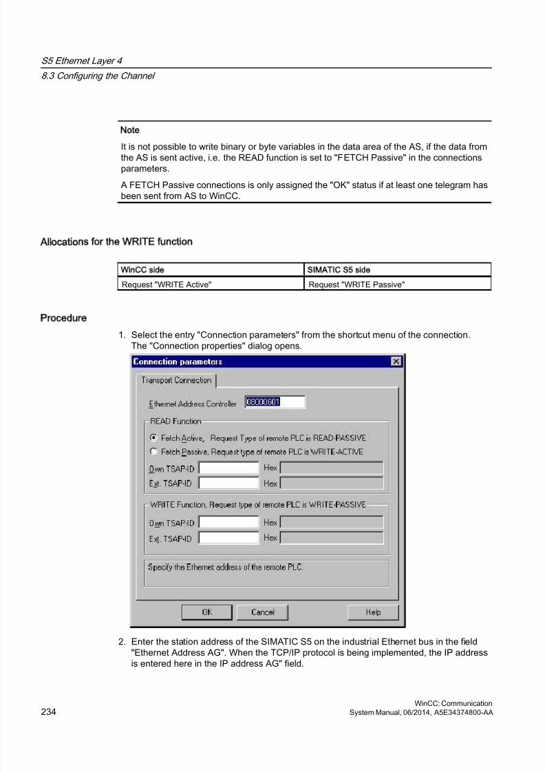
8/20/2019 WinCC Communication en-US en-US
http://slidepdf.com/reader/full/wincc-communication-en-us-en-us 234/527
Note
It is not possible to write binary or byte variables in the data area of the AS, if the data fromthe AS is sent active, i.e. the READ function is set to "FETCH Passive" in the connectionsparameters.
A FETCH Passive connections is only assigned the "OK" status if at least one telegram hasbeen sent from AS to WinCC.
Allocations for the WRITE function
WinCC side SIMATIC S5 side
Request "WRITE Active" Request "WRITE Passive"
Procedure
1. Select the entry "Connection parameters" from the shortcut menu of the connection.The "Connection properties" dialog opens.
2. Enter the station address of the SIMATIC S5 on the industrial Ethernet bus in the field"Ethernet Address AG". When the TCP/IP protocol is being implemented, the IP addressis entered here in the IP address AG" field.
S5 Ethernet Layer 4
8.3 Configuring the Channel
WinCC: Communication234 System Manual, 06/2014, A5E34374800-AA
8/20/2019 WinCC Communication en-US en-US
http://slidepdf.com/reader/full/wincc-communication-en-us-en-us 235/527
8/20/2019 WinCC Communication en-US en-US
http://slidepdf.com/reader/full/wincc-communication-en-us-en-us 236/527
single write request and the corresponding bits and/or bytes are modified. Afterwards, the datais written back to the AS's memory.
Note
Changes that have been made by the AS in a read data area are overwritten when writingback into the data area.
It is not possible to write binary or byte variables in the data area of the AS, if the data fromthe AS is sent active, i.e. the READ function is set to "FETCH Passive" in the connectionsparameters.
Configuring the address of a tag is done independent of the tag type:
● With tags of type "binary" or 8 bit value", first the "Bits-/Bytes-tag" dialog is opened, in whichthe bitwise or byte-wise access to the memory area of the AS is defined.Afterwards, the address of the tag in the AS memory is defined in the "Address properties"dialog.
● For word-oriented tags, the address of the tag in the AS memory is defined in the "Addressproperties" dialog.The dialog "Bits-/Bytes-tag" is not opened, since the access to the AS memory is word byword.
S5 Ethernet Layer 4
8.3 Configuring the Channel
WinCC: Communication236 System Manual, 06/2014, A5E34374800-AA

8/20/2019 WinCC Communication en-US en-US
http://slidepdf.com/reader/full/wincc-communication-en-us-en-us 237/527
8.3.3.3 How to Configure a Tag with Bit by Bit Access
Procedure
1. Select the connection and open the dialog window "Bit/Byte tag" in the shortcut menu.For this purpose, click in the "Address" field and then on the button.
2. Click the "Select" button. The "Bit/Byte tag" dialog is opened.
3. Use the check box to define whether access should be enabled for reading and writingcertain bits in the memory area.
4. Select the addressing methods for the AS memory in the selection field e.g. "Word" or "Byte".
5. Select the number of bits to be changed in the selection field.
6. Use the "Selection" button to open the "Address properties" dialog for defining the tagaddress in AS.
S5 Ethernet Layer 4
8.3 Configuring the Channel
WinCC: CommunicationSystem Manual, 06/2014, A5E34374800-AA 237
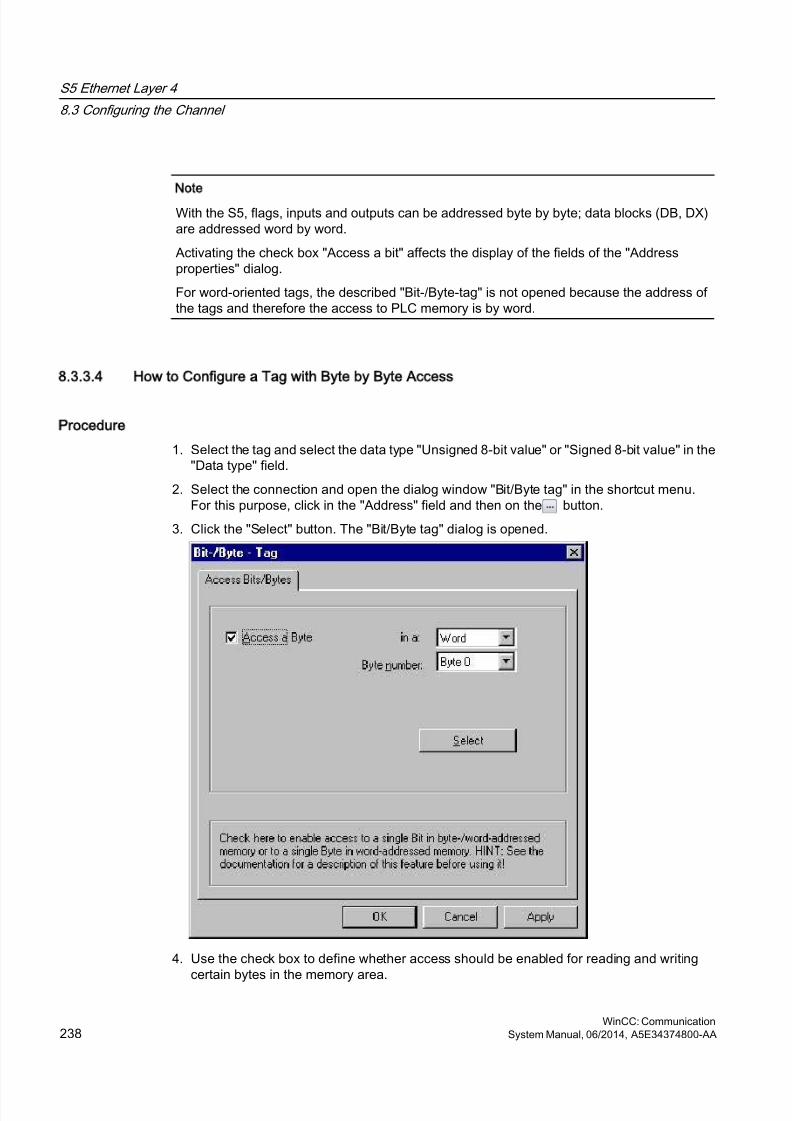
8/20/2019 WinCC Communication en-US en-US
http://slidepdf.com/reader/full/wincc-communication-en-us-en-us 238/527
Note
With the S5, flags, inputs and outputs can be addressed byte by byte; data blocks (DB, DX)are addressed word by word.
Activating the check box "Access a bit" affects the display of the fields of the "Addressproperties" dialog.
For word-oriented tags, the described "Bit-/Byte-tag" is not opened because the address ofthe tags and therefore the access to PLC memory is by word.
8.3.3.4 How to Configure a Tag with Byte by Byte Access
Procedure
1. Select the tag and select the data type "Unsigned 8-bit value" or "Signed 8-bit value" in the"Data type" field.
2. Select the connection and open the dialog window "Bit/Byte tag" in the shortcut menu.For this purpose, click in the "Address" field and then on the button.
3. Click the "Select" button. The "Bit/Byte tag" dialog is opened.
4. Use the check box to define whether access should be enabled for reading and writingcertain bytes in the memory area.
S5 Ethernet Layer 4
8.3 Configuring the Channel
WinCC: Communication238 System Manual, 06/2014, A5E34374800-AA
8/20/2019 WinCC Communication en-US en-US
http://slidepdf.com/reader/full/wincc-communication-en-us-en-us 239/527
5. Only "Word" is shown as the AS memory addressing type in the selection field.
6. Select the number of bytes to be changed in the selection field.
7. Use the "Selection" button to open the "Address properties" dialog for defining the tagaddress in AS.
Note
With the S5, flags, inputs and outputs can be addressed byte by byte; data blocks (DB, DX)are addressed word by word.
Selecting the check box "Access a byte" affects the display of the fields of the "Addressproperties" dialog.
For word-oriented tags, the described "Bit-/Byte-tag" is not opened because the address ofthe tags and therefore the access to PLC memory is by word.
8.3.3.5 How to Configure a Tag with Word by Word Access
Introduction
The addresses of tags in AS are defined with the dialog that is described here.
● With tags of type "binary" or 8 bit value", first the "Bits-/Bytes-tag" dialog is opened, in whichthe bitwise or byte-wise access to the memory area of the AS is defined.
● For word-oriented tags, the "Bit-/Byte-tag" dialog is not opened because the address of thetags and therefore the access to AS memory is by word.
S5 Ethernet Layer 4
8.3 Configuring the Channel
WinCC: CommunicationSystem Manual, 06/2014, A5E34374800-AA 239
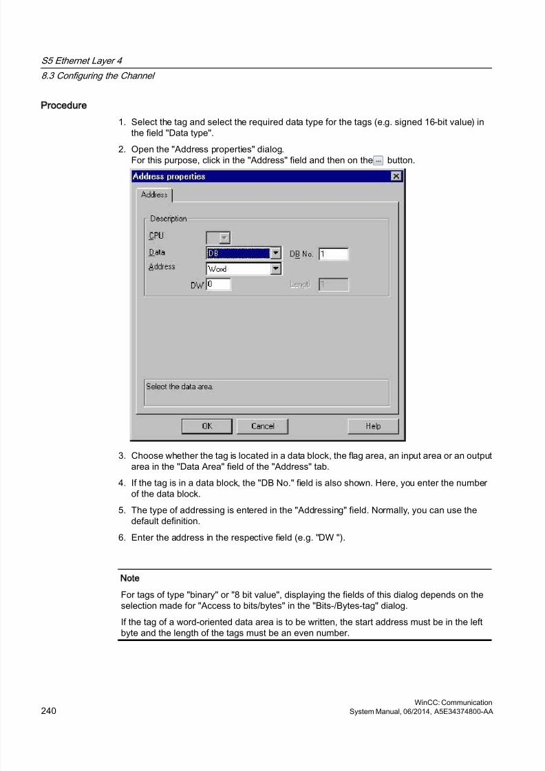
8/20/2019 WinCC Communication en-US en-US
http://slidepdf.com/reader/full/wincc-communication-en-us-en-us 240/527
Procedure
1. Select the tag and select the required data type for the tags (e.g. signed 16-bit value) in
the field "Data type".2. Open the "Address properties" dialog.
For this purpose, click in the "Address" field and then on the button.
3. Choose whether the tag is located in a data block, the flag area, an input area or an outputarea in the "Data Area" field of the "Address" tab.
4. If the tag is in a data block, the "DB No." field is also shown. Here, you enter the numberof the data block.
5. The type of addressing is entered in the "Addressing" field. Normally, you can use thedefault definition.
6. Enter the address in the respective field (e.g. "DW ").
Note
For tags of type "binary" or "8 bit value", displaying the fields of this dialog depends on theselection made for "Access to bits/bytes" in the "Bits-/Bytes-tag" dialog.
If the tag of a word-oriented data area is to be written, the start address must be in the leftbyte and the length of the tags must be an even number.
S5 Ethernet Layer 4
8.3 Configuring the Channel
WinCC: Communication240 System Manual, 06/2014, A5E34374800-AA
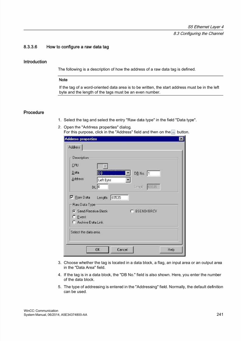
8/20/2019 WinCC Communication en-US en-US
http://slidepdf.com/reader/full/wincc-communication-en-us-en-us 241/527
8.3.3.6 How to configure a raw data tag
Introduction
The following is a description of how the address of a raw data tag is defined.
Note
If the tag of a word-oriented data area is to be written, the start address must be in the leftbyte and the length of the tags must be an even number.
Procedure
1. Select the tag and select the entry "Raw data type" in the field "Data type".2. Open the "Address properties" dialog.
For this purpose, click in the "Address" field and then on the button.
3. Choose whether the tag is located in a data block, a flag, an input area or an output areain the "Data Area" field.
4. If the tag is in a data block, the "DB No." field is also shown. Here, you enter the numberof the data block.
5. The type of addressing is entered in the "Addressing" field. Normally, the default definitioncan be used.
S5 Ethernet Layer 4
8.3 Configuring the Channel
WinCC: CommunicationSystem Manual, 06/2014, A5E34374800-AA 241
8/20/2019 WinCC Communication en-US en-US
http://slidepdf.com/reader/full/wincc-communication-en-us-en-us 242/527
6. Enter the data address in the field underneath. The label on the field depends on the entryin the "Addressing" field, e.g. "DBW" for Word addressing.
7. Enter the length of the raw data block in bytes in the Length field.8. Define which type of raw data tag is concerned in the "Raw data type" area.
8.3.4 System parameters
8.3.4.1 System parameters of the channel unit
Introduction
If you require a configuration that deviates from the standard WinCC settings, you can makeall the required changes using the "System Parameter" dialog of the channel unit.
The system parameters are almost identical for all protocols used. When implementing theTCP/IP protocol, only the device name given during the installation is different.
The following individual points can be changed:
● the device name
● the transport parameter
Note
The system parameters apply for all CPs in the AS.
Device Name
Communication between WinCC and the automation system takes place via logical devicenames. These names are assigned during the installation of the communication module andare unit-specific. The device name represents the logical device name. The logical devicename is given the name "/CP_H1_1:/ SCP" with the ISO transport protocol and "/TCP_IP:/SCP"with the TCP/IP protocol as a default definition.
Note
When using the TCP/IP protocol, you must check whether the device name in WinCCmatches the "Access point of the application" in the "Set PG/PC interface" dialog. The devicename must also be changed in "Set PG/PC interface".
Transport Parameter
Specific settings for the channel unit are made in the transport parameters, e.g. PDU size,setup attempts, etc.
S5 Ethernet Layer 4
8.3 Configuring the Channel
WinCC: Communication242 System Manual, 06/2014, A5E34374800-AA
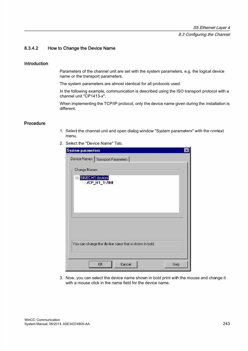
8/20/2019 WinCC Communication en-US en-US
http://slidepdf.com/reader/full/wincc-communication-en-us-en-us 243/527
8.3.4.2 How to Change the Device Name
Introduction
Parameters of the channel unit are set with the system parameters, e.g. the logical devicename or the transport parameters.
The system parameters are almost identical for all protocols used.
In the following example, communication is described using the ISO transport protocol with achannel unit "CP1413-x".
When implementing the TCP/IP protocol, only the device name given during the installation isdifferent.
Procedure
1. Select the channel unit and open dialog window "System parameters" with the contextmenu.
2. Select the "Device Name" Tab.
3. Now, you can select the device name shown in bold print with the mouse and change itwith a mouse click in the name field for the device name.
S5 Ethernet Layer 4
8.3 Configuring the Channel
WinCC: CommunicationSystem Manual, 06/2014, A5E34374800-AA 243

8/20/2019 WinCC Communication en-US en-US
http://slidepdf.com/reader/full/wincc-communication-en-us-en-us 244/527
Note
The device name is defined during the installation of the hardware driver. Only if you havedefined another name there, which is not recommended, will you have to change the devicename here as well.
8.3.4.3 How to change the transport parameter
Procedure
1. Select the channel unit and open dialog window "System parameters" with the contextmenu.
2. Select the "Transport parameter" tab.
3. Set the value for "PDU size" to the value that was configured on the communication moduleCP 1430.
4. Define how often a connection establishment should be attempted in the "Setup attempt"filed.
S5 Ethernet Layer 4
8.3 Configuring the Channel
WinCC: Communication244 System Manual, 06/2014, A5E34374800-AA

8/20/2019 WinCC Communication en-US en-US
http://slidepdf.com/reader/full/wincc-communication-en-us-en-us 245/527
5. Select "Infinite" in the "Duration of Send Repetitions" area.
6. Enter value e.g. 30 in the "Acknowledgement time" field so that you are informed of the tag
status after 30 seconds at the most, if the communication partner has not responded withinthis time (e.g. AS in "Stop" status).
S5 Ethernet Layer 4
8.3 Configuring the Channel
WinCC: CommunicationSystem Manual, 06/2014, A5E34374800-AA 245
8/20/2019 WinCC Communication en-US en-US
http://slidepdf.com/reader/full/wincc-communication-en-us-en-us 246/527
8.4 Appendix
8.4.1 Appendix
Introduction
Added information on the channel "SIMATIC S5 Ethernet Layer 4" is provided in the appendix.
8.4.2 Internal error codes and constants
8.4.2.1 Internal error codes and constants
Introduction
The following tables contain the most important error codes and constants. The information isintended for "insiders". Therefore, we have not gone into more detail on the meanings of thecodes and constants.
● Error codes during connection disturbances
● iNA960 messages
● SCI messages
8.4.2.2 Error codes during connection disturbances
Introduction
The most important error codes are listed in this section. If an error with an error code that isnot in the table occurs, please call the WinCC hotline.
Fehler_0002-INVALID_RQ
Faulty request block.
Fehler_0004-NO_RESOURCES
No resources free in CP.
Fehler_0006-UNKNOWN_REFERENCE
Incorrect OPEN reference defined.
S5 Ethernet Layer 4
8.4 Appendix
WinCC: Communication246 System Manual, 06/2014, A5E34374800-AA

8/20/2019 WinCC Communication en-US en-US
http://slidepdf.com/reader/full/wincc-communication-en-us-en-us 247/527
Fehler_0008-BUFFER_TOO_SHORT
User buffer too short.
Fehler_0010-BUFFER_TOO_LONG
User buffer too long.
Fehler_0012-ILLEGAL_REQ
Incorrect "negot_options" defined.
Fehler_0014-REM_ABORT
Connection aborted by remote station.
Fehler_0016-LOC_TIMEOUT
Timeout.
Fehler_0018-UNKNOWN_CONN_CLASS
Unknown connection class.
Fehler_0020-DUP_REQ
Connection already established.
Fehler_0022-CONN_REJECT
Connection request rejected by remote.
Fehler_0024-NEGOT_FAILED
Connection abort faulty "negot-option".
Fehler_0026-ILLEGAL_ADDRESS
Faulty transport address.
Fehler_0028-NETWORK_ERROR
Bus or CP disrupted.
Fehler_0030-PROTOCOL_ERR
Protocol error.
S5 Ethernet Layer 4
8.4 Appendix
WinCC: CommunicationSystem Manual, 06/2014, A5E34374800-AA 247
8/20/2019 WinCC Communication en-US en-US
http://slidepdf.com/reader/full/wincc-communication-en-us-en-us 248/527
Fehler_0032-ILLEGAL_RB_LENGTH
Incorrect request block length.
Fehler_0784-E_NO_HW
No communication hardware found.
● Communication module defective.
● Communication module not installed correctly.
● Wrong port address defined.
Fehler_0786-E_CNF
Driver configured incorrectly or invalid parameter in the registry.
Fehler_0787-E_BAUDRATE
Incorrect baudrate or incorrect interrupt vector defined.
Fehler_0788-E_HSA
Incorrect HSA (Highest Station Address) defined.
Fehler_0789-E_TS
The defined local participant number (TS_ADR) is already assigned.
Fehler_0791-E_INT_NOT_PROV
The defined interrupt vector (IRQ) is not available on the communication module.
Fehler_0792-E_INT_BUSY
The defined interrupt vector (IRQ) is already occupied on the communication module.
Fehler_0800-E_NO_FILE
The selected communication driver cannot be loaded; the file was not found.
● Communication driver not installed correctly.
Fehler_0897-E_LOGDEV
The logical device is not defined in the registry.
● Communication driver not installed correctly.
● Entry damaged or deleted in the registry.
S5 Ethernet Layer 4
8.4 Appendix
WinCC: Communication248 System Manual, 06/2014, A5E34374800-AA
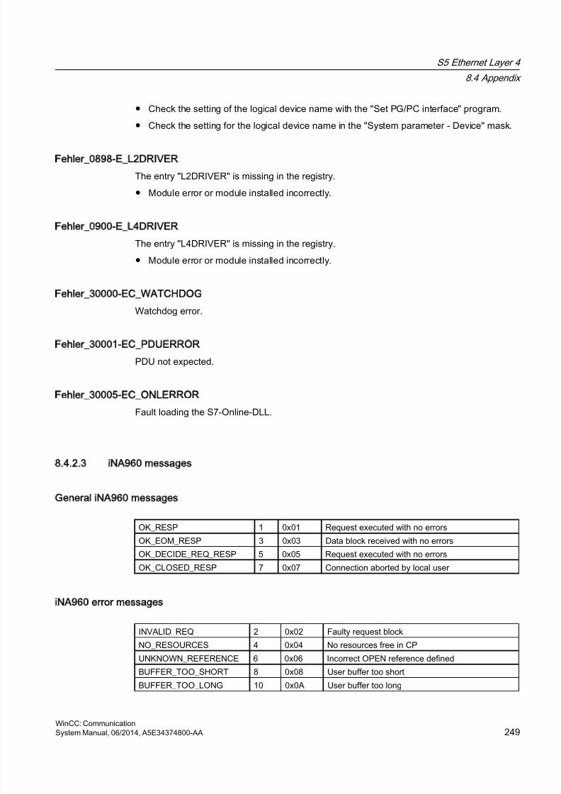
8/20/2019 WinCC Communication en-US en-US
http://slidepdf.com/reader/full/wincc-communication-en-us-en-us 249/527
● Check the setting of the logical device name with the "Set PG/PC interface" program.
● Check the setting for the logical device name in the "System parameter - Device" mask.
Fehler_0898-E_L2DRIVER
The entry "L2DRIVER" is missing in the registry.
● Module error or module installed incorrectly.
Fehler_0900-E_L4DRIVER
The entry "L4DRIVER" is missing in the registry.
● Module error or module installed incorrectly.
Fehler_30000-EC_WATCHDOG
Watchdog error.
Fehler_30001-EC_PDUERROR
PDU not expected.
Fehler_30005-EC_ONLERROR
Fault loading the S7-Online-DLL.
8.4.2.3 iNA960 messages
General iNA960 messages
OK_RESP 1 0x01 Request executed with no errors
OK_EOM_RESP 3 0x03 Data block received with no errors
OK_DECIDE_REQ_RESP 5 0x05 Request executed with no errorsOK_CLOSED_RESP 7 0x07 Connection aborted by local user
iNA960 error messages
INVALID_REQ 2 0x02 Faulty request block
NO_RESOURCES 4 0x04 No resources free in CP
UNKNOWN_REFERENCE 6 0x06 Incorrect OPEN reference defined
BUFFER_TOO_SHORT 8 0x08 User buffer too short
BUFFER_TOO_LONG 10 0x0A User buffer too long
S5 Ethernet Layer 4
8.4 Appendix
WinCC: CommunicationSystem Manual, 06/2014, A5E34374800-AA 249
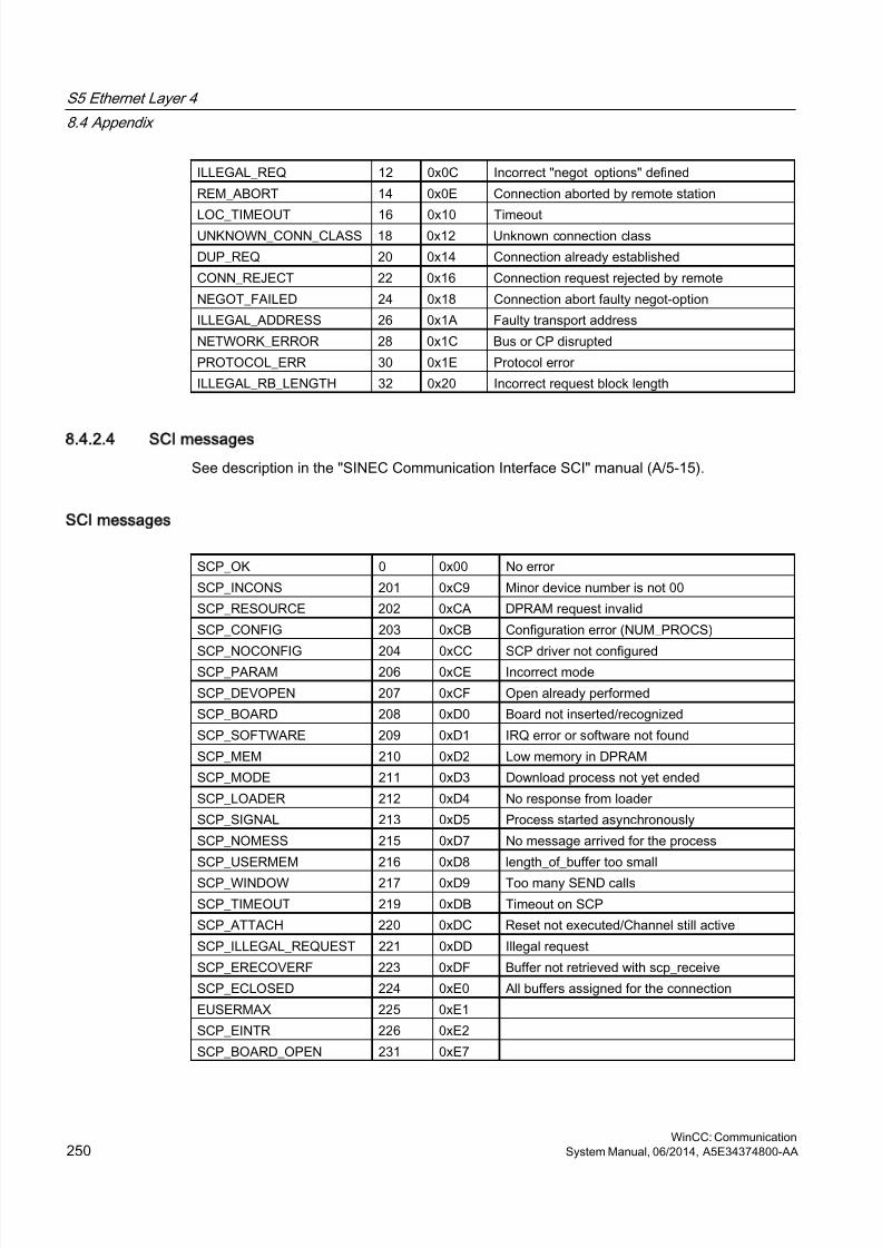
8/20/2019 WinCC Communication en-US en-US
http://slidepdf.com/reader/full/wincc-communication-en-us-en-us 250/527
ILLEGAL_REQ 12 0x0C Incorrect "negot_options" defined
REM_ABORT 14 0x0E Connection aborted by remote station
LOC_TIMEOUT 16 0x10 TimeoutUNKNOWN_CONN_CLASS 18 0x12 Unknown connection class
DUP_REQ 20 0x14 Connection already established
CONN_REJECT 22 0x16 Connection request rejected by remote
NEGOT_FAILED 24 0x18 Connection abort faulty negot-option
ILLEGAL_ADDRESS 26 0x1A Faulty transport address
NETWORK_ERROR 28 0x1C Bus or CP disrupted
PROTOCOL_ERR 30 0x1E Protocol error
ILLEGAL_RB_LENGTH 32 0x20 Incorrect request block length
8.4.2.4 SCI messages
See description in the "SINEC Communication Interface SCI" manual (A/5-15).
SCI messages
SCP_OK 0 0x00 No error
SCP_INCONS 201 0xC9 Minor device number is not 00
SCP_RESOURCE 202 0xCA DPRAM request invalid
SCP_CONFIG 203 0xCB Configuration error (NUM_PROCS)
SCP_NOCONFIG 204 0xCC SCP driver not configuredSCP_PARAM 206 0xCE Incorrect mode
SCP_DEVOPEN 207 0xCF Open already performed
SCP_BOARD 208 0xD0 Board not inserted/recognized
SCP_SOFTWARE 209 0xD1 IRQ error or software not found
SCP_MEM 210 0xD2 Low memory in DPRAM
SCP_MODE 211 0xD3 Download process not yet ended
SCP_LOADER 212 0xD4 No response from loader
SCP_SIGNAL 213 0xD5 Process started asynchronously
SCP_NOMESS 215 0xD7 No message arrived for the process
SCP_USERMEM 216 0xD8 length_of_buffer too small
SCP_WINDOW 217 0xD9 Too many SEND calls
SCP_TIMEOUT 219 0xDB Timeout on SCP
SCP_ATTACH 220 0xDC Reset not executed/Channel still active
SCP_ILLEGAL_REQUEST 221 0xDD Illegal request
SCP_ERECOVERF 223 0xDF Buffer not retrieved with scp_receive
SCP_ECLOSED 224 0xE0 All buffers assigned for the connection
EUSERMAX 225 0xE1
SCP_EINTR 226 0xE2
SCP_BOARD_OPEN 231 0xE7
S5 Ethernet Layer 4
8.4 Appendix
WinCC: Communication250 System Manual, 06/2014, A5E34374800-AA
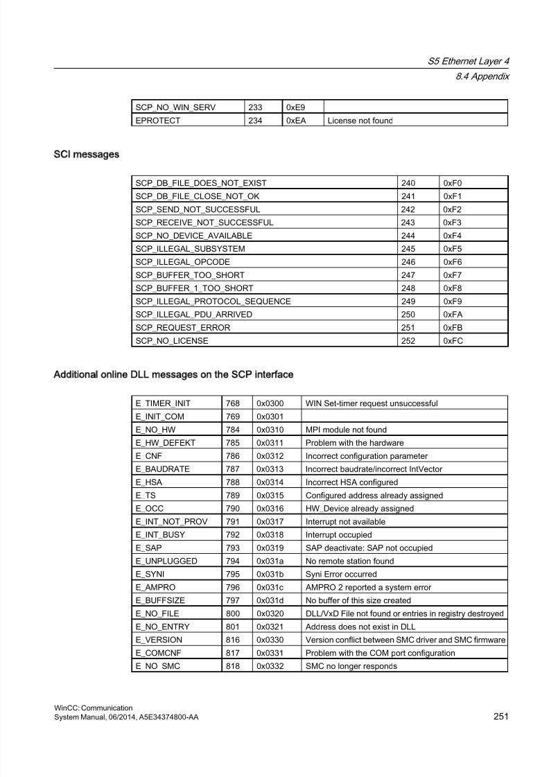
8/20/2019 WinCC Communication en-US en-US
http://slidepdf.com/reader/full/wincc-communication-en-us-en-us 251/527
SCP_NO_WIN_SERV 233 0xE9
EPROTECT 234 0xEA License not found
SCI messages
SCP_DB_FILE_DOES_NOT_EXIST 240 0xF0
SCP_DB_FILE_CLOSE_NOT_OK 241 0xF1
SCP_SEND_NOT_SUCCESSFUL 242 0xF2
SCP_RECEIVE_NOT_SUCCESSFUL 243 0xF3
SCP_NO_DEVICE_AVAILABLE 244 0xF4
SCP_ILLEGAL_SUBSYSTEM 245 0xF5
SCP_ILLEGAL_OPCODE 246 0xF6
SCP_BUFFER_TOO_SHORT 247 0xF7
SCP_BUFFER_1_TOO_SHORT 248 0xF8
SCP_ILLEGAL_PROTOCOL_SEQUENCE 249 0xF9
SCP_ILLEGAL_PDU_ARRIVED 250 0xFA
SCP_REQUEST_ERROR 251 0xFB
SCP_NO_LICENSE 252 0xFC
Additional online DLL messages on the SCP interface
E_TIMER_INIT 768 0x0300 WIN Set-timer request unsuccessful
E_INIT_COM 769 0x0301
E_NO_HW 784 0x0310 MPI module not found
E_HW_DEFEKT 785 0x0311 Problem with the hardware
E_CNF 786 0x0312 Incorrect configuration parameter
E_BAUDRATE 787 0x0313 Incorrect baudrate/incorrect IntVector
E_HSA 788 0x0314 Incorrect HSA configured
E_TS 789 0x0315 Configured address already assigned
E_OCC 790 0x0316 HW_Device already assigned
E_INT_NOT_PROV 791 0x0317 Interrupt not available
E_INT_BUSY 792 0x0318 Interrupt occupied
E_SAP 793 0x0319 SAP deactivate: SAP not occupied
E_UNPLUGGED 794 0x031a No remote station found
E_SYNI 795 0x031b Syni Error occurred
E_AMPRO 796 0x031c AMPRO 2 reported a system error
E_BUFFSIZE 797 0x031d No buffer of this size created
E_NO_FILE 800 0x0320 DLL/VxD File not found or entries in registry destroyed
E_NO_ENTRY 801 0x0321 Address does not exist in DLL
E_VERSION 816 0x0330 Version conflict between SMC driver and SMC firmware
E_COMCNF 817 0x0331 Problem with the COM port configuration
E_NO_SMC 818 0x0332 SMC no longer responds
S5 Ethernet Layer 4
8.4 Appendix
WinCC: CommunicationSystem Manual, 06/2014, A5E34374800-AA 251
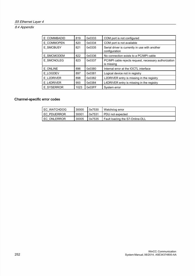
8/20/2019 WinCC Communication en-US en-US
http://slidepdf.com/reader/full/wincc-communication-en-us-en-us 252/527
E_COMMBADID 819 0x0333 COM port is not configured
E_COMMOPEN 820 0x0334 COM port is not available
E_SMCBUSY 821 0x0335 Serial driver is currently in use with anotherconfiguration
E_SMCMODEM 822 0x0336 No connection exists to a PC/MPI cable
E_SMCNOLEG 823 0x0337 PC/MPI cable rejects request, necessary authorizationis missing
E_ONLINE 896 0x0380 Internal error at the IOCTL interface
E_LOGDEV 897 0x0381 Logical device not in registry
E_L2DRIVER 898 0x0382 L2DRIVER entry is missing in the registry
E_L4DRIVER 900 0x0384 L4DRIVER entry is missing in the registry
E_SYSERROR 1023 0x03FF System error
Channel-specific error codes
EC_WATCHDOG 30000 0x7530 Watchdog error
EC_PDUERROR 30001 0x7531 PDU not expected
EC_ONLERROR 30005 0x7535 Fault loading the S7-Online-DLL
S5 Ethernet Layer 4
8.4 Appendix
WinCC: Communication252 System Manual, 06/2014, A5E34374800-AA

8/20/2019 WinCC Communication en-US en-US
http://slidepdf.com/reader/full/wincc-communication-en-us-en-us 253/527
8/20/2019 WinCC Communication en-US en-US
http://slidepdf.com/reader/full/wincc-communication-en-us-en-us 254/527
up to a maximum of 24 connections. In order for the channel to function, a channel unit and aconnection must be set up.
Service Access Point
SAPs are local data interfaces within a PROFIBUS node. The SAPs must be configured inWinCC and on the AS. A unique identification is defined with the Service Access Point. Thisunique identification is required for communication between the WinCC and the AS.
Active connection
An active connection is also called a Fetch connection. This is a connection, with which anactive partner retrieves data with a communication partner. The communication partner thatthe data is retrieved from is designated as a passive partner.
Passive connection
A passive connection exists if the active AS sends data to the passive WinCC partnerasynchronously without a request telegram.
S5 PROFIBUS FDL
9.1 WinCC channel "SIMATIC S5 Profibus FDL"
WinCC: Communication254 System Manual, 06/2014, A5E34374800-AA
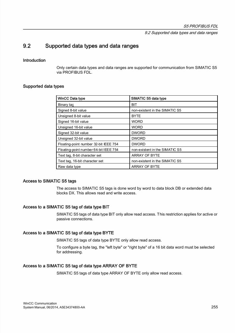
8/20/2019 WinCC Communication en-US en-US
http://slidepdf.com/reader/full/wincc-communication-en-us-en-us 255/527
9.2 Supported data types and data ranges
Introduction
Only certain data types and data ranges are supported for communication from SIMATIC S5via PROFIBUS FDL.
Supported data types
WinCC Data type SIMATIC S5 data type
Binary tag BIT
Signed 8-bit value non-existent in the SIMATIC S5
Unsigned 8-bit value BYTESigned 16-bit value WORD
Unsigned 16-bit value WORD
Signed 32-bit value DWORD
Unsigned 32-bit value DWORD
Floating-point number 32-bit IEEE 754 DWORD
Floating-point number 64-bit IEEE 754 non-existent in the SIMATIC S5
Text tag, 8-bit character set ARRAY OF BYTE
Text tag, 16-bit character set non-existent in the SIMATIC S5
Raw data type ARRAY OF BYTE
Access to SIMATIC S5 tags
The access to SIMATIC S5 tags is done word by word to data block DB or extended datablocks DX. This allows read and write access.
Access to a SIMATIC S5 tag of data type BIT
SIMATIC S5 tags of data type BIT only allow read access. This restriction applies for active orpassive connections.
Access to a SIMATIC S5 tag of data type BYTE
SIMATIC S5 tags of data type BYTE only allow read access.
To configure a byte tag, the "left byte" or "right byte" of a 16 bit data word must be selectedfor addressing.
Access to a SIMATIC S5 tag of data type ARRAY OF BYTE
SIMATIC S5 tags of data type ARRAY OF BYTE only allow read access.
S5 PROFIBUS FDL
9.2 Supported data types and data ranges
WinCC: CommunicationSystem Manual, 06/2014, A5E34374800-AA 255
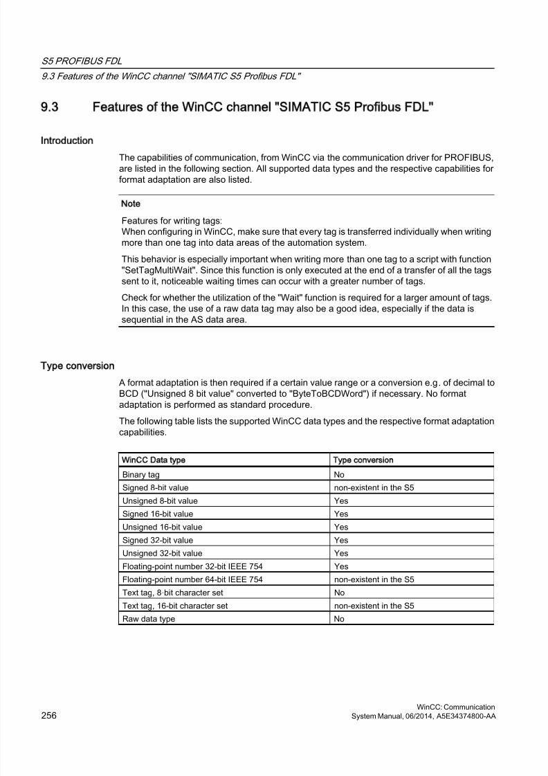
8/20/2019 WinCC Communication en-US en-US
http://slidepdf.com/reader/full/wincc-communication-en-us-en-us 256/527
9.3 Features of the WinCC channel SIMATIC S5 Profibus FDL
Introduction
The capabilities of communication, from WinCC via the communication driver for PROFIBUS,are listed in the following section. All supported data types and the respective capabilities forformat adaptation are also listed.
Note
Features for writing tags:When configuring in WinCC, make sure that every tag is transferred individually when writingmore than one tag into data areas of the automation system.
This behavior is especially important when writing more than one tag to a script with function
"SetTagMultiWait". Since this function is only executed at the end of a transfer of all the tagssent to it, noticeable waiting times can occur with a greater number of tags.
Check for whether the utilization of the "Wait" function is required for a larger amount of tags.In this case, the use of a raw data tag may also be a good idea, especially if the data issequential in the AS data area.
Type conversion
A format adaptation is then required if a certain value range or a conversion e.g. of decimal toBCD ("Unsigned 8 bit value" converted to "ByteToBCDWord") if necessary. No format
adaptation is performed as standard procedure.The following table lists the supported WinCC data types and the respective format adaptationcapabilities.
WinCC Data type Type conversion
Binary tag No
Signed 8-bit value non-existent in the S5
Unsigned 8-bit value Yes
Signed 16-bit value Yes
Unsigned 16-bit value Yes
Signed 32-bit value YesUnsigned 32-bit value Yes
Floating-point number 32-bit IEEE 754 Yes
Floating-point number 64-bit IEEE 754 non-existent in the S5
Text tag, 8-bit character set No
Text tag, 16-bit character set non-existent in the S5
Raw data type No
S5 PROFIBUS FDL
9.3 Features of the WinCC channel "SIMATIC S5 Profibus FDL"
WinCC: Communication256 System Manual, 06/2014, A5E34374800-AA
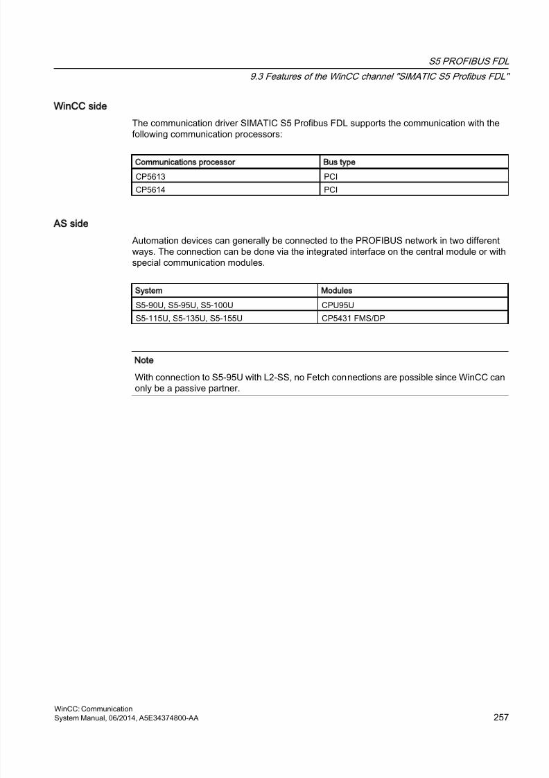
8/20/2019 WinCC Communication en-US en-US
http://slidepdf.com/reader/full/wincc-communication-en-us-en-us 257/527
WinCC side
The communication driver SIMATIC S5 Profibus FDL supports the communication with the
following communication processors:
Communications processor Bus type
CP5613 PCI
CP5614 PCI
AS side
Automation devices can generally be connected to the PROFIBUS network in two differentways. The connection can be done via the integrated interface on the central module or withspecial communication modules.
System Modules
S5-90U, S5-95U, S5-100U CPU95U
S5-115U, S5-135U, S5-155U CP5431 FMS/DP
Note
With connection to S5-95U with L2-SS, no Fetch connections are possible since WinCC canonly be a passive partner.
S5 PROFIBUS FDL
9.3 Features of the WinCC channel "SIMATIC S5 Profibus FDL"
WinCC: CommunicationSystem Manual, 06/2014, A5E34374800-AA 257
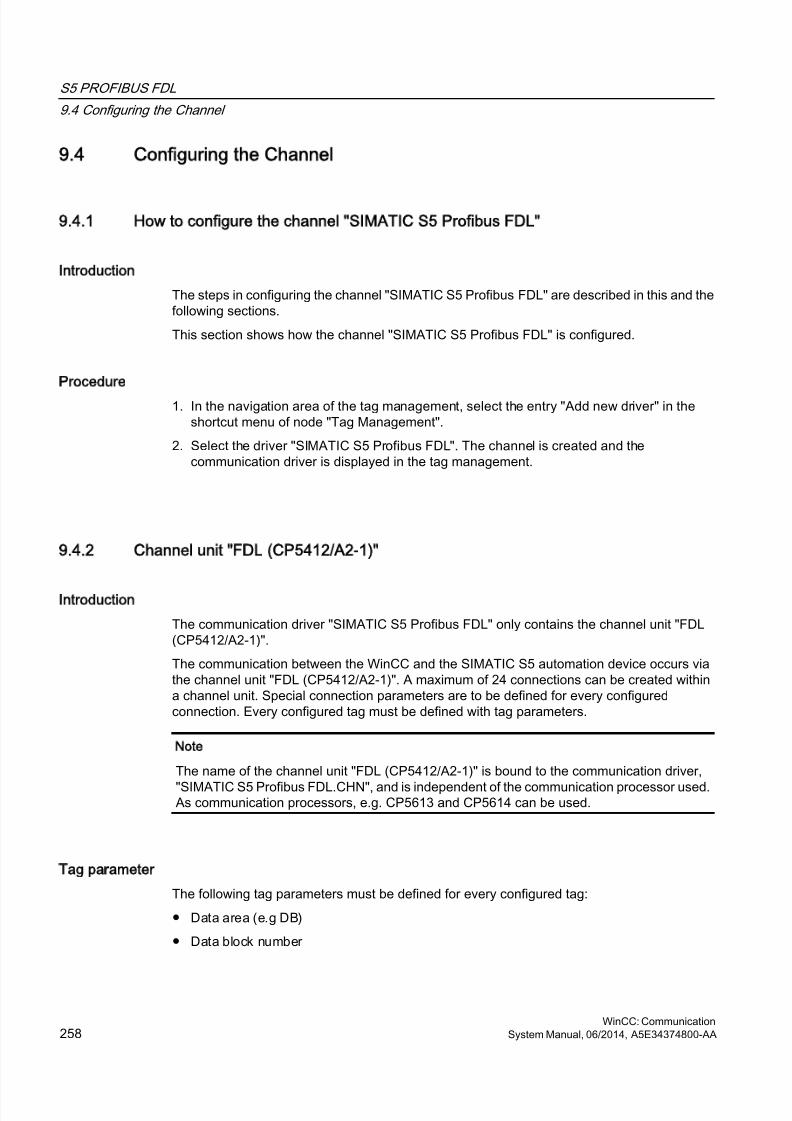
8/20/2019 WinCC Communication en-US en-US
http://slidepdf.com/reader/full/wincc-communication-en-us-en-us 258/527
9.4 Configuring the Channel
9.4.1 How to configure the channel SIMATIC S5 Profibus FDL
Introduction
The steps in configuring the channel "SIMATIC S5 Profibus FDL" are described in this and thefollowing sections.
This section shows how the channel "SIMATIC S5 Profibus FDL" is configured.
Procedure
1. In the navigation area of the tag management, select the entry "Add new driver" in theshortcut menu of node "Tag Management".
2. Select the driver "SIMATIC S5 Profibus FDL". The channel is created and thecommunication driver is displayed in the tag management.
9.4.2 Channel unit FDL (CP5412/A2-1)
Introduction
The communication driver "SIMATIC S5 Profibus FDL" only contains the channel unit "FDL(CP5412/A2-1)".
The communication between the WinCC and the SIMATIC S5 automation device occurs viathe channel unit "FDL (CP5412/A2-1)". A maximum of 24 connections can be created withina channel unit. Special connection parameters are to be defined for every configuredconnection. Every configured tag must be defined with tag parameters.
Note
The name of the channel unit "FDL (CP5412/A2-1)" is bound to the communication driver,
"SIMATIC S5 Profibus FDL.CHN", and is independent of the communication processor used.As communication processors, e.g. CP5613 and CP5614 can be used.
Tag parameter
The following tag parameters must be defined for every configured tag:
● Data area (e.g DB)
● Data block number
S5 PROFIBUS FDL
9.4 Configuring the Channel
WinCC: Communication258 System Manual, 06/2014, A5E34374800-AA
8/20/2019 WinCC Communication en-US en-US
http://slidepdf.com/reader/full/wincc-communication-en-us-en-us 259/527
● Addressing (e.g. "left byte")
● Start address (e.g. DL 0, if "left byte" has been selected for addressing)
Connection parameters
The following connection parameters must be defined for every configured connection:
● The station address of the AS
● The priority
● Own and foreign SAPs (Service Access Point) must be defined for the read and writefunction
For the read function, configuring whether it should be an active or a passive connection isalso necessary. For an active read connection, the values are requested from the WinCC
station. For a passive connection, the transfer of the values to the WinCC station is initiatedby the AS.
9.4.3 How to configure a connection
Requirements
● The channel "SIMATIC S5 Profibus FDL" must be integrated in the project.
Procedure
1. Select the channel unit "FDL (CP5412/A2-1)".
2. Select the entry "New Connection" in the shortcut menu of the channel unit.
3. Enter the name of the connection.
S5 PROFIBUS FDL
9.4 Configuring the Channel
WinCC: CommunicationSystem Manual, 06/2014, A5E34374800-AA 259
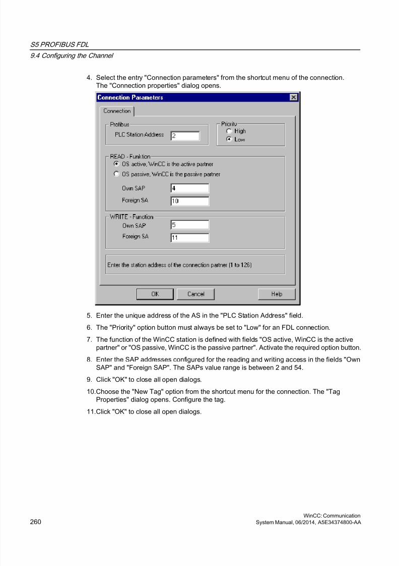
8/20/2019 WinCC Communication en-US en-US
http://slidepdf.com/reader/full/wincc-communication-en-us-en-us 260/527
4. Select the entry "Connection parameters" from the shortcut menu of the connection.The "Connection properties" dialog opens.
5. Enter the unique address of the AS in the "PLC Station Address" field.
6. The "Priority" option button must always be set to "Low" for an FDL connection.
7. The function of the WinCC station is defined with fields "OS active, WinCC is the activepartner" or "OS passive, WinCC is the passive partner". Activate the required option button.
8. Enter the SAP addresses configured for the reading and writing access in the fields "OwnSAP" and "Foreign SAP". The SAPs value range is between 2 and 54.
9. Click "OK" to close all open dialogs.
10.Choose the "New Tag" option from the shortcut menu for the connection. The "TagProperties" dialog opens. Configure the tag.
11.Click "OK" to close all open dialogs.
S5 PROFIBUS FDL
9.4 Configuring the Channel
WinCC: Communication260 System Manual, 06/2014, A5E34374800-AA
8/20/2019 WinCC Communication en-US en-US
http://slidepdf.com/reader/full/wincc-communication-en-us-en-us 261/527
9.4.4 Configuring the tags
9.4.4.1 Configuring the tags
Introduction
For a connection between WinCC and the AS via channel "SIMATIC S5 Profibus FDL", datatypes binary, byte and word can be defined within WinCC. The following describes how toconfigure a tag of these data types.
9.4.4.2 How to Configure a Tag with Bit by Bit Access
Introduction
This section shows you how to configure a tag for bit by bit access for the address area in theAS.
Note
The bit by bit access to a tag is only read access.
Requirements
1. The channel "SIMATIC S5 Profibus FDL" must be integrated in the project.
2. A connection must be defined in the channel unit "FDL (CP5412/A2-1)".
Procedure
1. Select the connection for which a tag is to be configured.
2. Click the "Tags" tab below the table area.
3. Click in the top free cell of the "Name" column.Enter the name for the tag.
4. Set the "Binary tag" data type in the "Data Type" field.
S5 PROFIBUS FDL
9.4 Configuring the Channel
WinCC: CommunicationSystem Manual, 06/2014, A5E34374800-AA 261
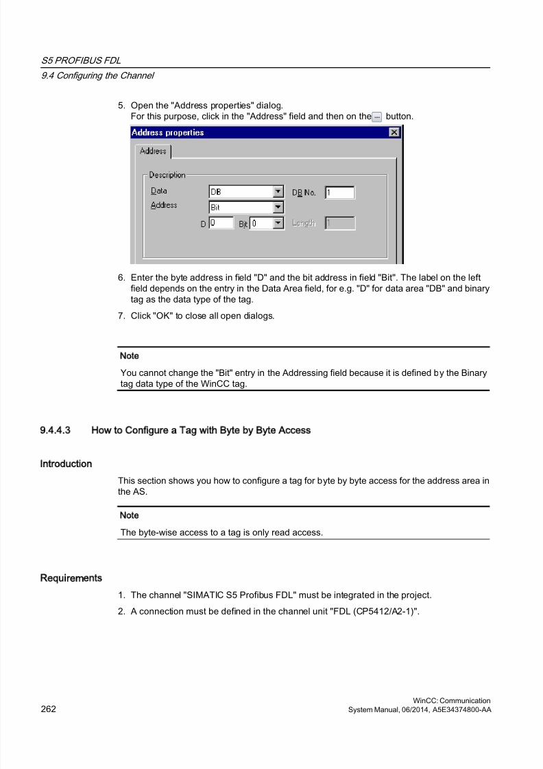
8/20/2019 WinCC Communication en-US en-US
http://slidepdf.com/reader/full/wincc-communication-en-us-en-us 262/527
5. Open the "Address properties" dialog.For this purpose, click in the "Address" field and then on the button.
6. Enter the byte address in field "D" and the bit address in field "Bit". The label on the leftfield depends on the entry in the Data Area field, for e.g. "D" for data area "DB" and binarytag as the data type of the tag.
7. Click "OK" to close all open dialogs.
Note
You cannot change the "Bit" entry in the Addressing field because it is defined by the Binarytag data type of the WinCC tag.
9.4.4.3 How to Configure a Tag with Byte by Byte Access
Introduction
This section shows you how to configure a tag for byte by byte access for the address area inthe AS.
Note
The byte-wise access to a tag is only read access.
Requirements
1. The channel "SIMATIC S5 Profibus FDL" must be integrated in the project.
2. A connection must be defined in the channel unit "FDL (CP5412/A2-1)".
S5 PROFIBUS FDL
9.4 Configuring the Channel
WinCC: Communication262 System Manual, 06/2014, A5E34374800-AA
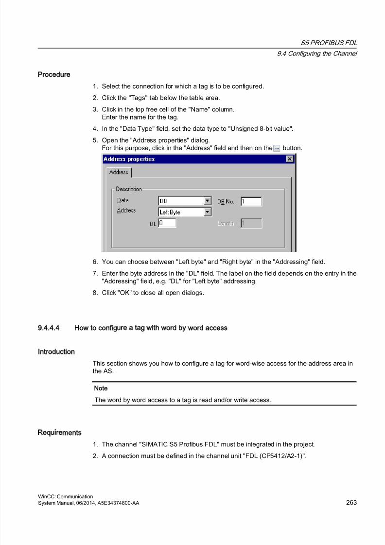
8/20/2019 WinCC Communication en-US en-US
http://slidepdf.com/reader/full/wincc-communication-en-us-en-us 263/527
Procedure
1. Select the connection for which a tag is to be configured.
2. Click the "Tags" tab below the table area.
3. Click in the top free cell of the "Name" column.Enter the name for the tag.
4. In the "Data Type" field, set the data type to "Unsigned 8-bit value".
5. Open the "Address properties" dialog.For this purpose, click in the "Address" field and then on the button.
6. You can choose between "Left byte" and "Right byte" in the "Addressing" field.
7. Enter the byte address in the "DL" field. The label on the field depends on the entry in the"Addressing" field, e.g. "DL" for "Left byte" addressing.
8. Click "OK" to close all open dialogs.
9.4.4.4 How to configure a tag with word by word access
Introduction
This section shows you how to configure a tag for word-wise access for the address area inthe AS.
Note
The word by word access to a tag is read and/or write access.
Requirements
1. The channel "SIMATIC S5 Profibus FDL" must be integrated in the project.
2. A connection must be defined in the channel unit "FDL (CP5412/A2-1)".
S5 PROFIBUS FDL
9.4 Configuring the Channel
WinCC: CommunicationSystem Manual, 06/2014, A5E34374800-AA 263
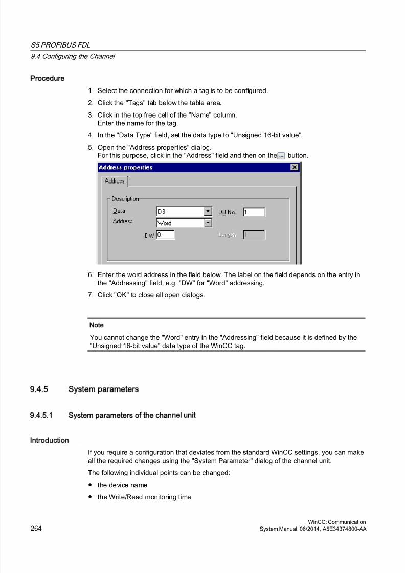
8/20/2019 WinCC Communication en-US en-US
http://slidepdf.com/reader/full/wincc-communication-en-us-en-us 264/527
Procedure
1. Select the connection for which a tag is to be configured.
2. Click the "Tags" tab below the table area.
3. Click in the top free cell of the "Name" column.Enter the name for the tag.
4. In the "Data Type" field, set the data type to "Unsigned 16-bit value".
5. Open the "Address properties" dialog.For this purpose, click in the "Address" field and then on the button.
6. Enter the word address in the field below. The label on the field depends on the entry inthe "Addressing" field, e.g. "DW" for "Word" addressing.
7. Click "OK" to close all open dialogs.
Note
You cannot change the "Word" entry in the "Addressing" field because it is defined by the"Unsigned 16-bit value" data type of the WinCC tag.
9.4.5 System parameters
9.4.5.1 System parameters of the channel unit
Introduction
If you require a configuration that deviates from the standard WinCC settings, you can makeall the required changes using the "System Parameter" dialog of the channel unit.
The following individual points can be changed:
● the device name
● the Write/Read monitoring time
S5 PROFIBUS FDL
9.4 Configuring the Channel
WinCC: Communication264 System Manual, 06/2014, A5E34374800-AA
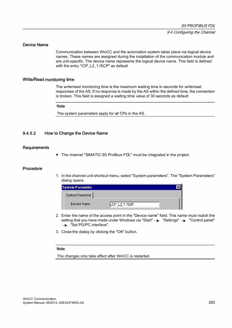
8/20/2019 WinCC Communication en-US en-US
http://slidepdf.com/reader/full/wincc-communication-en-us-en-us 265/527
Device Name
Communication between WinCC and the automation system takes place via logical device
names. These names are assigned during the installation of the communication module andare unit-specific. The device name represents the logical device name. This field is definedwith the entry "/CP_L2_1:/SCP" as default.
Write/Read monitoring time
The write/read monitoring time is the maximum waiting time in seconds for write/readresponses of the AS. If no response is made by the AS within the defined time, the connectionis broken. This field is assigned a waiting time value of 30 seconds as default
Note
The system parameters apply for all CPs in the AS.
9.4.5.2 How to Change the Device Name
Requirements
● The channel "SIMATIC S5 Profibus FDL" must be integrated in the project.
Procedure
1. In the channel unit shortcut menu, select "System parameters". The "System Parameters"dialog opens.
2. Enter the name of the access point in the "Device name" field. This name must match thesetting that you have made under Windows via "Start" "Settings" "Control panel"
"Set PG/PC interface".
3. Close the dialog by clicking the "OK" button.
Note
The changes only take effect after WinCC is restarted.
S5 PROFIBUS FDL
9.4 Configuring the Channel
WinCC: CommunicationSystem Manual, 06/2014, A5E34374800-AA 265
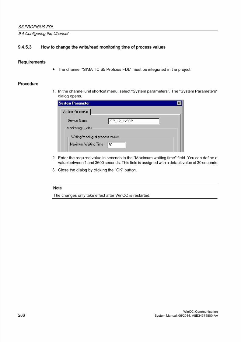
8/20/2019 WinCC Communication en-US en-US
http://slidepdf.com/reader/full/wincc-communication-en-us-en-us 266/527
9.4.5.3 How to change the write/read monitoring time of process values
Requirements
● The channel "SIMATIC S5 Profibus FDL" must be integrated in the project.
Procedure
1. In the channel unit shortcut menu, select "System parameters". The "System Parameters"dialog opens.
2. Enter the required value in seconds in the "Maximum waiting time" field. You can define avalue between 1 and 3600 seconds. This field is assigned with a default value of 30 seconds.
3. Close the dialog by clicking the "OK" button.
Note
The changes only take effect after WinCC is restarted.
S5 PROFIBUS FDL
9.4 Configuring the Channel
WinCC: Communication266 System Manual, 06/2014, A5E34374800-AA
8/20/2019 WinCC Communication en-US en-US
http://slidepdf.com/reader/full/wincc-communication-en-us-en-us 267/527
9.5 Special Functions
9.5.1 Special functions of the SIMATIC S5 Profibus FDL Channel
Introduction
The "SIMATIC S5 Profibus FDL" channel has some special functions, the functionality of whichis described in this chapter.
9.5.2 Raw data tags of the SIMATIC S5 Profibus FDL channel
9.5.2.1 Raw data tags of the SIMATIC S5 Profibus FDL channel
Introduction
A tag of the type "raw data type" is a data telegram.
Raw data tags are required for transferring user data blocks from/to the AS
A raw data tag used by SIMATIC S5 Profibus FDL can be a maximum of 220 bytes in length.
Raw data tag as byte array
A raw data tag as byte array is handled like a normal process tag that is addressed via theaddress and length of the data block (for e.g. DB 100, DW 20, length 40 Byte).
Writing raw data tags using scripts
If a raw data tag, which is longer than the tag length configured in WinCC, is written to S5 usinga VB script, the write process is aborted.
Instead write the raw data tag via a C script using the "SetTagRaw" function. For this function,specify the length of the tags that are to be written.
9.5.2.2 How to configure raw data tags
Requirements
1. The channel "SIMATIC S5 Profibus FDL" must be integrated in the project.
2. A connection must be defined in the channel unit "FDL (CP5412/A2-1)".
S5 PROFIBUS FDL
9.5 Special Functions
WinCC: CommunicationSystem Manual, 06/2014, A5E34374800-AA 267
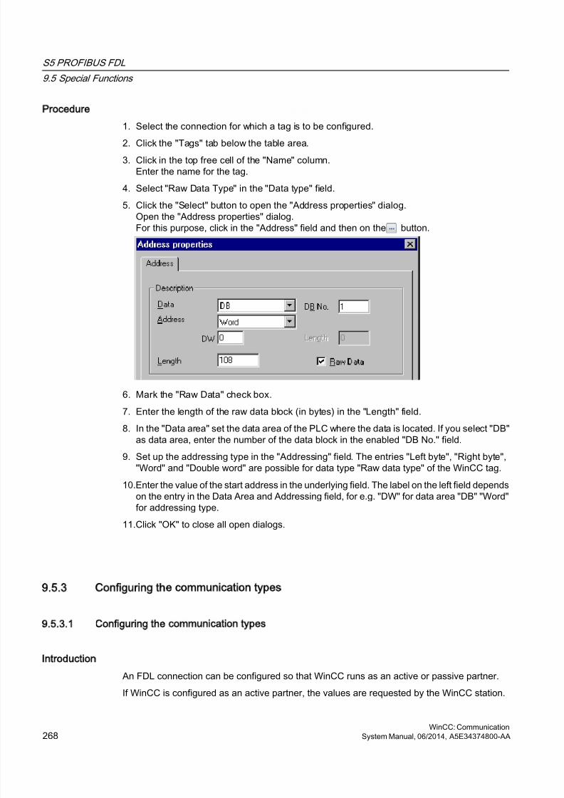
8/20/2019 WinCC Communication en-US en-US
http://slidepdf.com/reader/full/wincc-communication-en-us-en-us 268/527
Procedure
1. Select the connection for which a tag is to be configured.
2. Click the "Tags" tab below the table area.
3. Click in the top free cell of the "Name" column.Enter the name for the tag.
4. Select "Raw Data Type" in the "Data type" field.
5. Click the "Select" button to open the "Address properties" dialog.Open the "Address properties" dialog.For this purpose, click in the "Address" field and then on the button.
6. Mark the "Raw Data" check box.
7. Enter the length of the raw data block (in bytes) in the "Length" field.
8. In the "Data area" set the data area of the PLC where the data is located. If you select "DB"as data area, enter the number of the data block in the enabled "DB No." field.
9. Set up the addressing type in the "Addressing" field. The entries "Left byte", "Right byte","Word" and "Double word" are possible for data type "Raw data type" of the WinCC tag.
10.Enter the value of the start address in the underlying field. The label on the left field dependson the entry in the Data Area and Addressing field, for e.g. "DW" for data area "DB" "Word"for addressing type.
11.Click "OK" to close all open dialogs.
9.5.3 Configuring the communication types
9.5.3.1 Configuring the communication types
Introduction
An FDL connection can be configured so that WinCC runs as an active or passive partner.
If WinCC is configured as an active partner, the values are requested by the WinCC station.
S5 PROFIBUS FDL
9.5 Special Functions
WinCC: Communication268 System Manual, 06/2014, A5E34374800-AA
8/20/2019 WinCC Communication en-US en-US
http://slidepdf.com/reader/full/wincc-communication-en-us-en-us 269/527
If WinCC is configured as a passive partner, the transfer of values to the WinCC station isinitiated by the AS.
9.5.3.2 How to configure an active data transfer
Introduction
This section shows you how to configure an active data transfer to the address area in the AS.
Note
If more than one connection is configured, note that an SAP can only be assigned one time.
Requirements
1. The channel "SIMATIC S5 Profibus FDL" must be integrated in the project.
2. A connection must be defined in the channel unit "FDL (CP5412/A2-1)".
3. You must know the SAP address defined by the AS.
S5 PROFIBUS FDL
9.5 Special Functions
WinCC: CommunicationSystem Manual, 06/2014, A5E34374800-AA 269
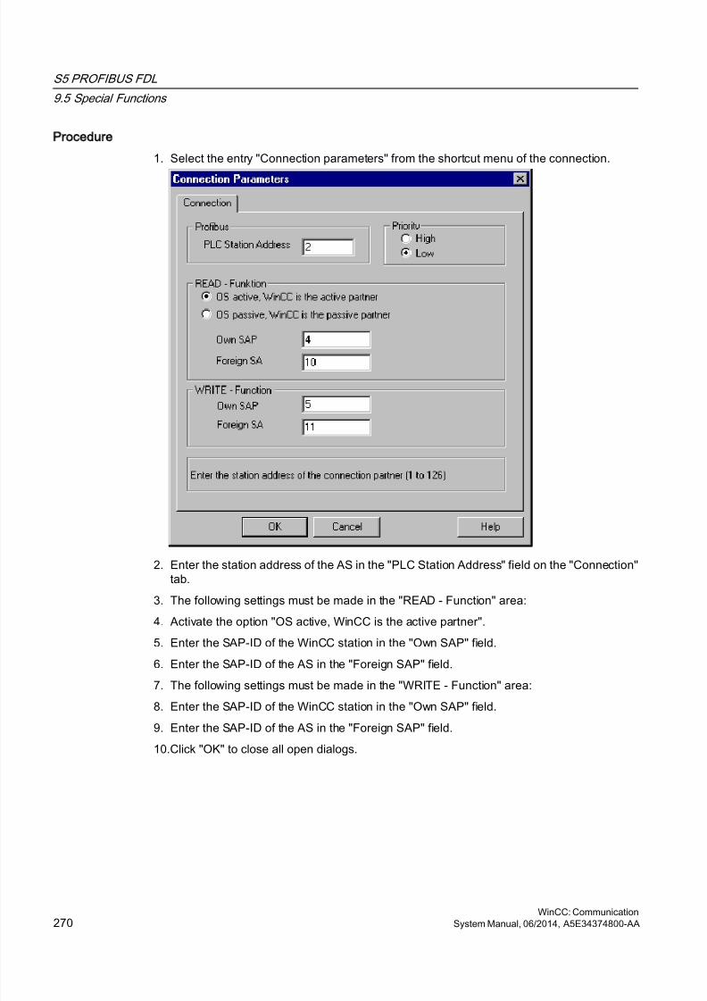
8/20/2019 WinCC Communication en-US en-US
http://slidepdf.com/reader/full/wincc-communication-en-us-en-us 270/527
Procedure
1. Select the entry "Connection parameters" from the shortcut menu of the connection.
2. Enter the station address of the AS in the "PLC Station Address" field on the "Connection"tab.
3. The following settings must be made in the "READ - Function" area:
4. Activate the option "OS active, WinCC is the active partner".
5. Enter the SAP-ID of the WinCC station in the "Own SAP" field.
6. Enter the SAP-ID of the AS in the "Foreign SAP" field.
7. The following settings must be made in the "WRITE - Function" area:
8. Enter the SAP-ID of the WinCC station in the "Own SAP" field.
9. Enter the SAP-ID of the AS in the "Foreign SAP" field.
10.Click "OK" to close all open dialogs.
S5 PROFIBUS FDL
9.5 Special Functions
WinCC: Communication270 System Manual, 06/2014, A5E34374800-AA
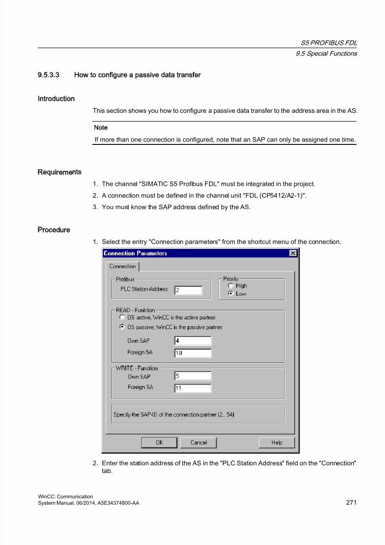
8/20/2019 WinCC Communication en-US en-US
http://slidepdf.com/reader/full/wincc-communication-en-us-en-us 271/527
9.5.3.3 How to configure a passive data transfer
Introduction
This section shows you how to configure a passive data transfer to the address area in the AS.
Note
If more than one connection is configured, note that an SAP can only be assigned one time.
Requirements
1. The channel "SIMATIC S5 Profibus FDL" must be integrated in the project.
2. A connection must be defined in the channel unit "FDL (CP5412/A2-1)".
3. You must know the SAP address defined by the AS.
Procedure
1. Select the entry "Connection parameters" from the shortcut menu of the connection.
2. Enter the station address of the AS in the "PLC Station Address" field on the "Connection"tab.
S5 PROFIBUS FDL
9.5 Special Functions
WinCC: CommunicationSystem Manual, 06/2014, A5E34374800-AA 271

8/20/2019 WinCC Communication en-US en-US
http://slidepdf.com/reader/full/wincc-communication-en-us-en-us 272/527
3. The following settings must be made in the "READ - Function" area:
4. Activate the option "OS passive, WinCC is the passive partner".
5. Enter the SAP-ID of the WinCC station in the "Own SAP" field.
6. Enter the SAP-ID of the AS in the "Foreign SAP" field.
7. The following settings must be made in the "WRITE - Function" area:
8. Enter the SAP-ID of the WinCC station in the "Own SAP" field.
9. Enter the SAP-ID of the AS in the "Foreign SAP" field.
10.Click "OK" to close all open dialogs.
S5 PROFIBUS FDL
9.5 Special Functions
WinCC: Communication272 System Manual, 06/2014, A5E34374800-AA
8/20/2019 WinCC Communication en-US en-US
http://slidepdf.com/reader/full/wincc-communication-en-us-en-us 273/527
9.6 Example of configuring the SIMATIC S5 Profibus FDL channel
9.6.1 Example of configuring the SIMATIC S5 Profibus FDL channel
Introduction
In this example, you will configure an I/O Field in the Graphics Designer and assign thenecessary values to the data handling blocks in the AS.
9.6.2 How to configure the data handling blocks in the AS
Introduction
In this section, you will configure the standard function blocks OB 21 (L2ANLAUF) and OB 1(L2SNDRCV) in the AS.
By default, the data traffic for the SIMATIC S5 connection by means of PROFIBUS FDL ishandled by means of the following blocks.
Within the example, the following SAP numbers are used:
WinCC Automation device
SAP number for the READfunction
12 6
SAP number for the WRITE
function
11 4
Blocks
Function Block
For the startup OB 20, 21, 22 FB-L2ANLAUF (FB 9)
For cyclic operation OB 1 FB-L2SNDRCV (FB 10)
As internal work DBs for both FBs DB-L2DBVC3 (DB 10)DB-L2DBVC4 (DB 11)DB-L2DBVC5 (DB 12)
Startup blocks
The communication parameters are defined in the startup blocks, the work DBs are logged inand the communication processor is synchronized. These work steps are executed by callingfunction block FB9 L2ANLAUF, for example.
S5 PROFIBUS FDL
9.6 Example of configuring the "SIMATIC S5 Profibus FDL" channel
WinCC: CommunicationSystem Manual, 06/2014, A5E34374800-AA 273

8/20/2019 WinCC Communication en-US en-US
http://slidepdf.com/reader/full/wincc-communication-en-us-en-us 274/527
Cyclic block
The telegram traffic is handled in the cyclic FB. Received telegrams are entered in the
destination data blocks. Should an error occur while this is being done, the telegram is rejectedand an error message is issued. Telegrams that have to be sent will be specified by the userin a similar manner to the standard data handling blocks. An acknowledgement is sent whenthe transfer has been completed.
S5 PROFIBUS FDL
9.6 Example of configuring the "SIMATIC S5 Profibus FDL" channel
WinCC: Communication274 System Manual, 06/2014, A5E34374800-AA
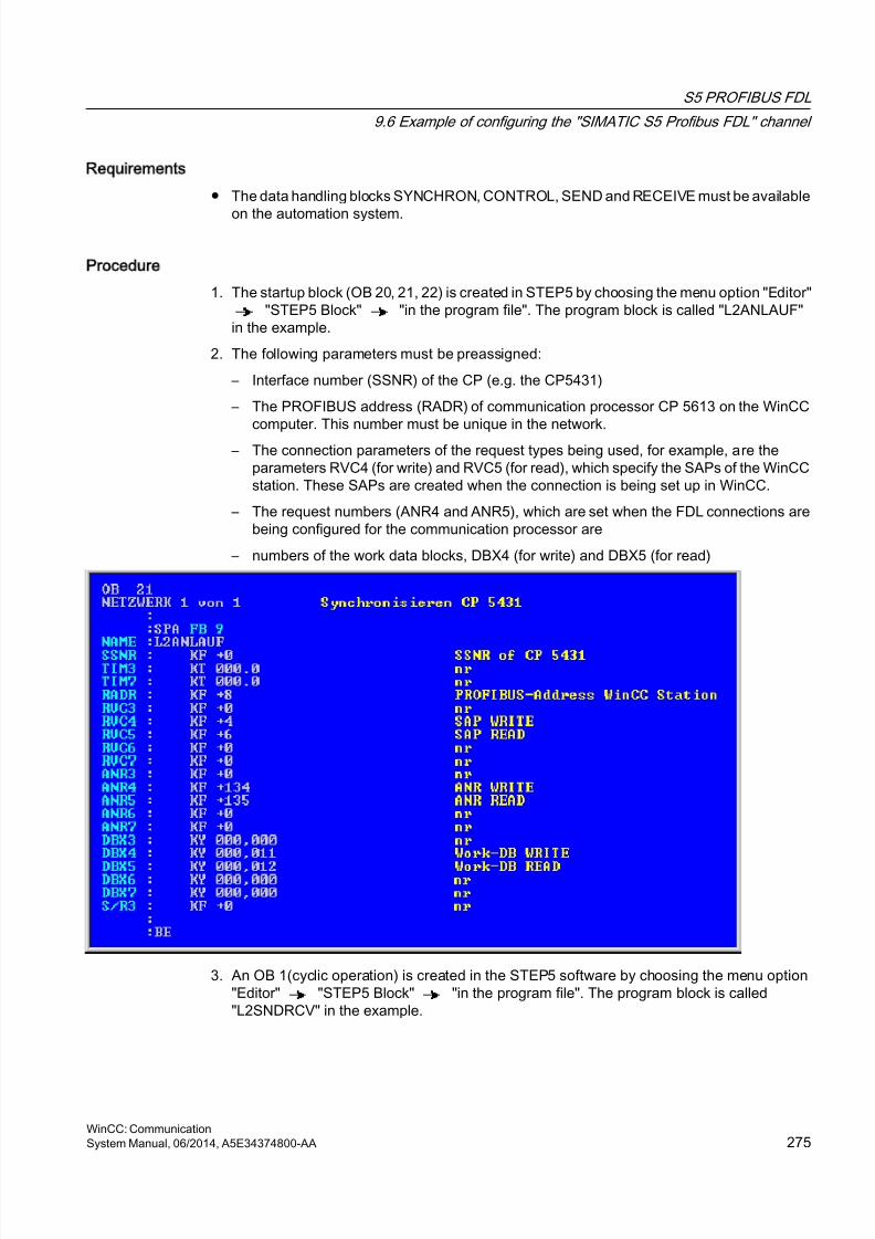
8/20/2019 WinCC Communication en-US en-US
http://slidepdf.com/reader/full/wincc-communication-en-us-en-us 275/527
Requirements
● The data handling blocks SYNCHRON, CONTROL, SEND and RECEIVE must be available
on the automation system.
Procedure
1. The startup block (OB 20, 21, 22) is created in STEP5 by choosing the menu option "Editor""STEP5 Block" "in the program file". The program block is called "L2ANLAUF"
in the example.
2. The following parameters must be preassigned:
– Interface number (SSNR) of the CP (e.g. the CP5431)
– The PROFIBUS address (RADR) of communication processor CP 5613 on the WinCCcomputer. This number must be unique in the network.
– The connection parameters of the request types being used, for example, are theparameters RVC4 (for write) and RVC5 (for read), which specify the SAPs of the WinCCstation. These SAPs are created when the connection is being set up in WinCC.
– The request numbers (ANR4 and ANR5), which are set when the FDL connections arebeing configured for the communication processor are
– numbers of the work data blocks, DBX4 (for write) and DBX5 (for read)
3. An OB 1(cyclic operation) is created in the STEP5 software by choosing the menu option"Editor" "STEP5 Block" "in the program file". The program block is called"L2SNDRCV" in the example.
S5 PROFIBUS FDL
9.6 Example of configuring the "SIMATIC S5 Profibus FDL" channel
WinCC: CommunicationSystem Manual, 06/2014, A5E34374800-AA 275
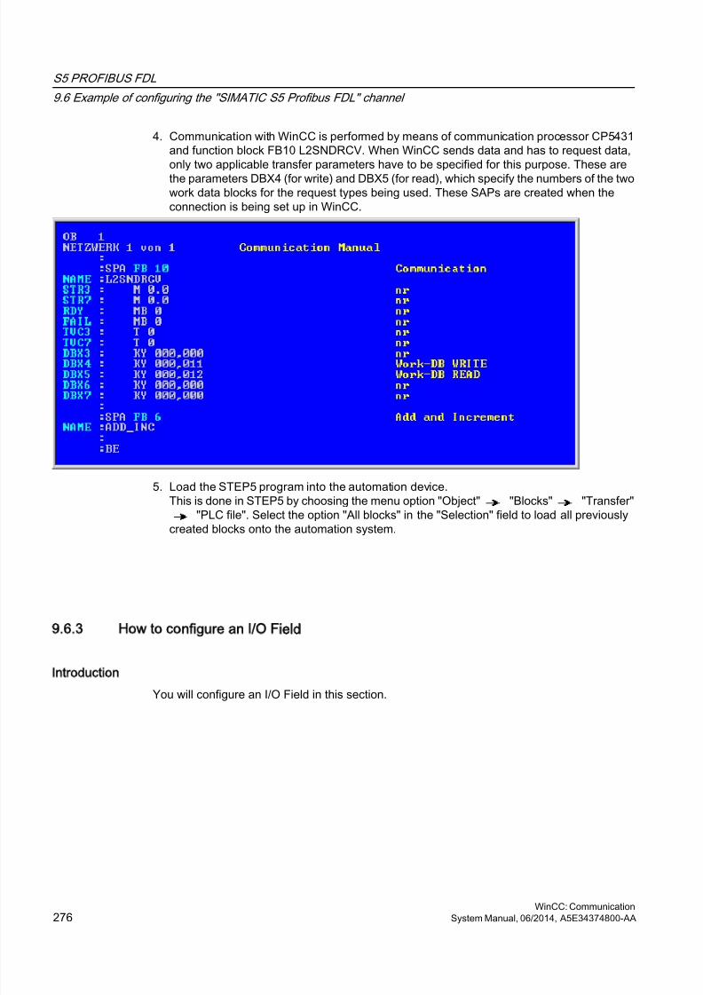
8/20/2019 WinCC Communication en-US en-US
http://slidepdf.com/reader/full/wincc-communication-en-us-en-us 276/527
4. Communication with WinCC is performed by means of communication processor CP5431and function block FB10 L2SNDRCV. When WinCC sends data and has to request data,only two applicable transfer parameters have to be specified for this purpose. These are
the parameters DBX4 (for write) and DBX5 (for read), which specify the numbers of the twowork data blocks for the request types being used. These SAPs are created when theconnection is being set up in WinCC.
5. Load the STEP5 program into the automation device.This is done in STEP5 by choosing the menu option "Object" "Blocks" "Transfer"
"PLC file". Select the option "All blocks" in the "Selection" field to load all previouslycreated blocks onto the automation system.
9.6.3 How to configure an I/O Field
Introduction
You will configure an I/O Field in this section.
S5 PROFIBUS FDL
9.6 Example of configuring the "SIMATIC S5 Profibus FDL" channel
WinCC: Communication276 System Manual, 06/2014, A5E34374800-AA
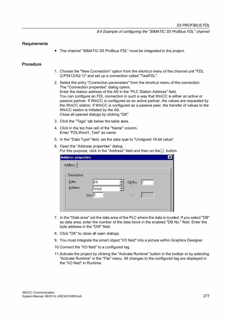
8/20/2019 WinCC Communication en-US en-US
http://slidepdf.com/reader/full/wincc-communication-en-us-en-us 277/527
Requirements
● The channel "SIMATIC S5 Profibus FDL" must be integrated in the project.
Procedure
1. Choose the "New Connection" option from the shortcut menu of the channel unit "FDL(CP5412/A2-1)" and set up a connection called "TestFDL".
2. Select the entry "Connection parameters" from the shortcut menu of the connection.The "Connection properties" dialog opens.Enter the station address of the AS in the "PLC Station Address" field.You can configure an FDL connection in such a way that WinCC is either an active orpassive partner. If WinCC is configured as an active partner, the values are requested bythe WinCC station. If WinCC is configured as a passive peer, the transfer of values to theWinCC station is initiated by the AS.Close all opened dialogs by clicking "OK"
3. Click the "Tags" tab below the table area.
4. Click in the top free cell of the "Name" column.Enter "FDLWord1_Test" as name.
5. In the "Data Type" field, set the data type to "Unsigned 16-bit value".
6. Open the "Address properties" dialog.For this purpose, click in the "Address" field and then on the button.
7. In the "Data area" set the data area of the PLC where the data is located. If you select "DB"as data area, enter the number of the data block in the enabled "DB No." field. Enter thebyte address in the "DW" field.
8. Click "OK" to close all open dialogs.
9. You must integrate the smart object "I/O field" into a picture within Graphics Designer.
10.Connect the "I/O field" to a configured tag.
11.Activate the project by clicking the "Activate Runtime" button in the toolbar or by selecting"Activate Runtime" in the "File" menu. All changes to the configured tag are displayed inthe "I/O field" in Runtime.
S5 PROFIBUS FDL
9.6 Example of configuring the "SIMATIC S5 Profibus FDL" channel
WinCC: CommunicationSystem Manual, 06/2014, A5E34374800-AA 277

8/20/2019 WinCC Communication en-US en-US
http://slidepdf.com/reader/full/wincc-communication-en-us-en-us 278/527
8/20/2019 WinCC Communication en-US en-US
http://slidepdf.com/reader/full/wincc-communication-en-us-en-us 279/527
S5 Programmers Port AS511
10
10.1 WinCC channel SIMATIC S5 Programmers Port AS511
Introduction
The communication driver "SIMATIC S5 Programmers Port AS511" is utilized for the serialconnection through a TTY interface to the SIMATIC S5 automation system.
This chapter describes
● how to configure the data transfer with the "SIMATIC S5 Programmers Port AS511" channel.
● how to configure a connection and a tag.
Channel Unit
The communication driver has one channel unit for controlling a COM port for the serialconnection.
The following capability is available:
● Channel unit S5-AS511 for serial communication via a "Siemens-specific" protocol.
WinCC: CommunicationSystem Manual, 06/2014, A5E34374800-AA 279

8/20/2019 WinCC Communication en-US en-US
http://slidepdf.com/reader/full/wincc-communication-en-us-en-us 280/527
10.2 Data type of the tags
Introduction
Define the required tags for a logical connection. From the WinCC viewpoint, you can accessthe following data types:
● Binary tag
● Unsigned 8-bit value
● Signed 8-bit value
● Unsigned 16-bit value
● Signed 16-bit value
● Unsigned 32-bit value● Signed 32-bit value
● Floating-point number 32-bit IEEE 754
● Text tag, 8-bit character set
● Raw data type
S5 Programmers Port AS511
10.2 Data type of the tags
WinCC: Communication280 System Manual, 06/2014, A5E34374800-AA
8/20/2019 WinCC Communication en-US en-US
http://slidepdf.com/reader/full/wincc-communication-en-us-en-us 281/527
10.3 Configuring the Channel
10.3.1 Configuring the SIMATIC S5 Programmers Port AS511 channel
Introduction
The following steps are required for configuring the channel "SIMATIC S5 Programmers PortAS511".
● Configuring the connection
● Configuring the tags
10.3.2 How to configure the connection
Introduction
The process connection using a serial connection is possible with the SIMATIC S5 automationsystem. The AS 511 communication processor is used in the automation system.
No additional communication module is required in WinCC. Communication is set up via eitherthe TTY port on a PG 760 or a COM Port that is part of the system's standard equipment. Inthe later case, an additional port converter is required V.24/V.28 <---> TTY.
This serial link supports transmission rates of up to 19200 baud.
The following procedure can be used to assign one of the PC's serial ports to the AS511-NTdrivers.
Note
During communication between WinCC and a S5 automation system via the "AS511"channel, data blocks may not be transferred, created or deleted in the AS. The memory inthe S5 may also not be compressed. This last restriction is the result of the absoluteaddressing of memory in the S5. If changes are necessary, the link to WinCC must bedisconnected.
S5 Programmers Port AS511
10.3 Configuring the Channel
WinCC: CommunicationSystem Manual, 06/2014, A5E34374800-AA 281
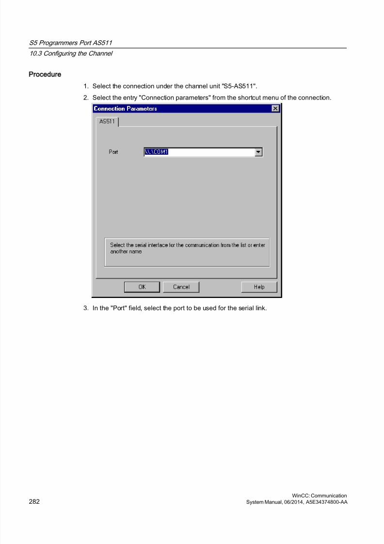
8/20/2019 WinCC Communication en-US en-US
http://slidepdf.com/reader/full/wincc-communication-en-us-en-us 282/527
Procedure
1. Select the connection under the channel unit "S5-AS511".
2. Select the entry "Connection parameters" from the shortcut menu of the connection.
3. In the "Port" field, select the port to be used for the serial link.
S5 Programmers Port AS511
10.3 Configuring the Channel
WinCC: Communication282 System Manual, 06/2014, A5E34374800-AA
8/20/2019 WinCC Communication en-US en-US
http://slidepdf.com/reader/full/wincc-communication-en-us-en-us 283/527
10.3.3 Configuring the tags
10.3.3.1 Configuring the tags
Introduction
For a connection between WinCC and the AS via channel "SIMATIC S5 Programmers PortAS511", tags of different data types can be created within WinCC. This is described in thefollowing section.
Note
Addresses of the tags are not checked for plausibility in WinCC. If an address is used, which
is not available in the AS, the status "Addressing error" will be set.In DB and DX data blocks, reads and writes can only be made up to address 255.
Times cannot be written.
10.3.3.2 How to configure the address of a tag
Introduction
The tag address is entered according to the address structure of the SIMATIC S5.
Procedure
1. Select the connection for which a tag is to be configured.
2. Click the "Tags" tab below the table area and select the tag.
3. Select the required data type (e.g. signed 8-bit value) from the "General" tab.
S5 Programmers Port AS511
10.3 Configuring the Channel
WinCC: CommunicationSystem Manual, 06/2014, A5E34374800-AA 283
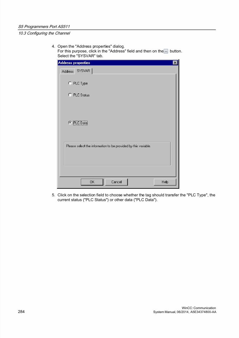
8/20/2019 WinCC Communication en-US en-US
http://slidepdf.com/reader/full/wincc-communication-en-us-en-us 284/527
4. Open the "Address properties" dialog.For this purpose, click in the "Address" field and then on the button.Select the "SYSVAR" tab.
5. Click on the selection field to choose whether the tag should transfer the "PLC Type", thecurrent status ("PLC Status") or other data ("PLC Data").
S5 Programmers Port AS511
10.3 Configuring the Channel
WinCC: Communication284 System Manual, 06/2014, A5E34374800-AA
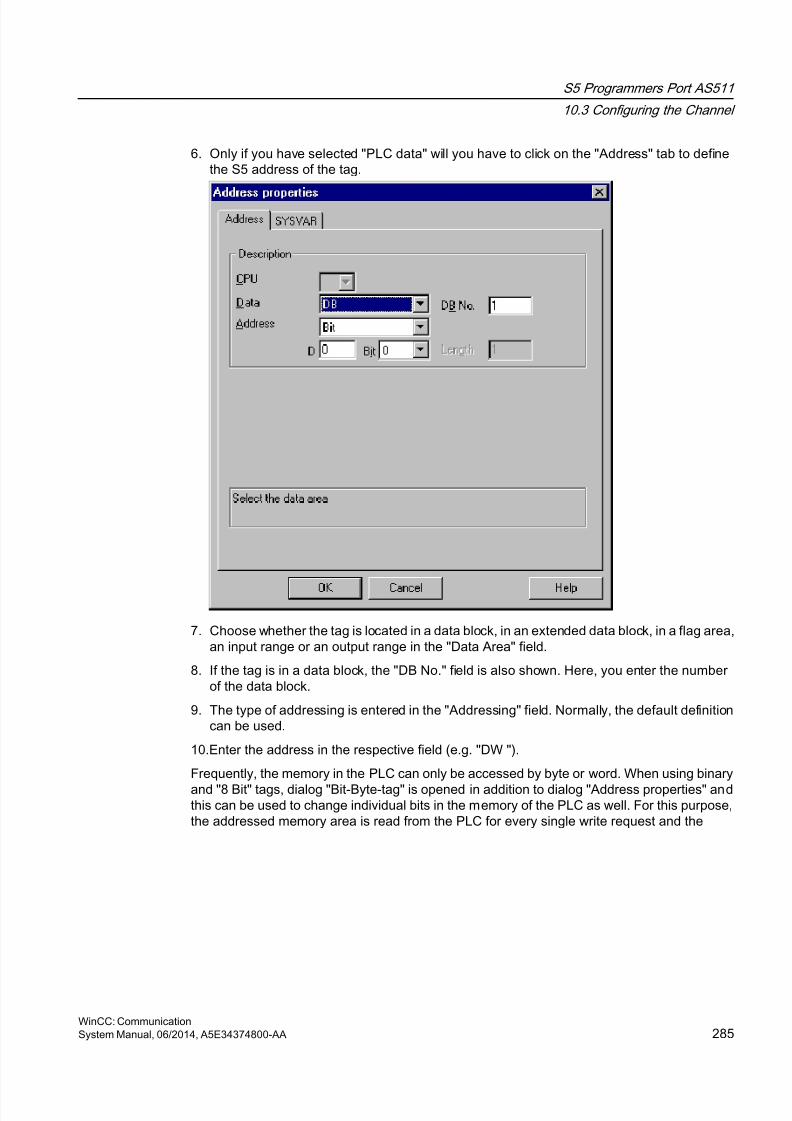
8/20/2019 WinCC Communication en-US en-US
http://slidepdf.com/reader/full/wincc-communication-en-us-en-us 285/527
6. Only if you have selected "PLC data" will you have to click on the "Address" tab to definethe S5 address of the tag.
7. Choose whether the tag is located in a data block, in an extended data block, in a flag area,an input range or an output range in the "Data Area" field.
8. If the tag is in a data block, the "DB No." field is also shown. Here, you enter the numberof the data block.
9. The type of addressing is entered in the "Addressing" field. Normally, the default definitioncan be used.
10.Enter the address in the respective field (e.g. "DW ").
Frequently, the memory in the PLC can only be accessed by byte or word. When using binary
and "8 Bit" tags, dialog "Bit-Byte-tag" is opened in addition to dialog "Address properties" andthis can be used to change individual bits in the memory of the PLC as well. For this purpose,the addressed memory area is read from the PLC for every single write request and the
S5 Programmers Port AS511
10.3 Configuring the Channel
WinCC: CommunicationSystem Manual, 06/2014, A5E34374800-AA 285
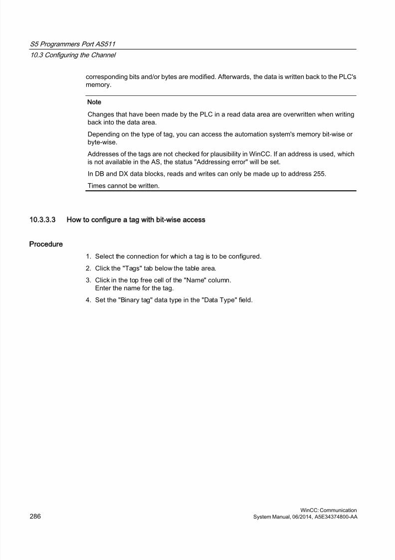
8/20/2019 WinCC Communication en-US en-US
http://slidepdf.com/reader/full/wincc-communication-en-us-en-us 286/527
corresponding bits and/or bytes are modified. Afterwards, the data is written back to the PLC'smemory.
Note
Changes that have been made by the PLC in a read data area are overwritten when writingback into the data area.
Depending on the type of tag, you can access the automation system's memory bit-wise orbyte-wise.
Addresses of the tags are not checked for plausibility in WinCC. If an address is used, whichis not available in the AS, the status "Addressing error" will be set.
In DB and DX data blocks, reads and writes can only be made up to address 255.
Times cannot be written.
10.3.3.3 How to configure a tag with bit-wise access
Procedure
1. Select the connection for which a tag is to be configured.
2. Click the "Tags" tab below the table area.
3. Click in the top free cell of the "Name" column.Enter the name for the tag.
4. Set the "Binary tag" data type in the "Data Type" field.
S5 Programmers Port AS511
10.3 Configuring the Channel
WinCC: Communication286 System Manual, 06/2014, A5E34374800-AA
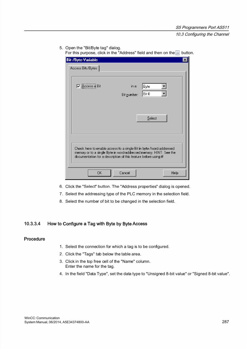
8/20/2019 WinCC Communication en-US en-US
http://slidepdf.com/reader/full/wincc-communication-en-us-en-us 287/527
5. Open the "Bit/Byte tag" dialog.For this purpose, click in the "Address" field and then on the button.
6. Click the "Select" button. The "Address properties" dialog is opened.
7. Select the addressing type of the PLC memory in the selection field.
8. Select the number of bit to be changed in the selection field.
10.3.3.4 How to Configure a Tag with Byte by Byte Access
Procedure
1. Select the connection for which a tag is to be configured.
2. Click the "Tags" tab below the table area.
3. Click in the top free cell of the "Name" column.Enter the name for the tag.
4. In the field "Data Type", set the data type to "Unsigned 8-bit value" or "Signed 8-bit value".
S5 Programmers Port AS511
10.3 Configuring the Channel
WinCC: CommunicationSystem Manual, 06/2014, A5E34374800-AA 287
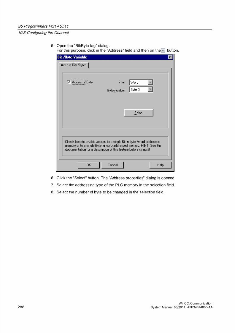
8/20/2019 WinCC Communication en-US en-US
http://slidepdf.com/reader/full/wincc-communication-en-us-en-us 288/527
5. Open the "Bit/Byte tag" dialog.For this purpose, click in the "Address" field and then on the button.
6. Click the "Select" button. The "Address properties" dialog is opened.
7. Select the addressing type of the PLC memory in the selection field.
8. Select the number of byte to be changed in the selection field.
S5 Programmers Port AS511
10.3 Configuring the Channel
WinCC: Communication288 System Manual, 06/2014, A5E34374800-AA
8/20/2019 WinCC Communication en-US en-US
http://slidepdf.com/reader/full/wincc-communication-en-us-en-us 289/527
S5 Serial 3964R
11
11.1 WinCC channel SIMATIC S5 Serial 3964R
Introduction
The communication driver "SIMATIC S5 Serial 3964R" is implemented for the serial linkbetween a WinCC station and a SIMATIC S5 automation system.
This chapter describes
● how to configure the data transfer with the "SIMATIC S5 Serial 3964R" channel.
● how to configure a connection and a tag.
Channel Unit
The communication driver has one channel unit for controlling a COM port for the serial link.
The following capability is available:
● Channel unit S5-RK512 (3964R) for serial communication via the 3964R or 3964 protocol.
WinCC: CommunicationSystem Manual, 06/2014, A5E34374800-AA 289

8/20/2019 WinCC Communication en-US en-US
http://slidepdf.com/reader/full/wincc-communication-en-us-en-us 290/527
11.2 Data type of the tags
Introduction
Define the required tags for a logical connection. From the WinCC viewpoint, you can accessthe following data types:
● Binary tag
● Unsigned 8-bit value
● Signed 8-bit value
● Unsigned 16-bit value
● Signed 16-bit value
● Unsigned 32-bit value● Signed 32-bit value
● Floating-point number 32-bit IEEE 754
● Text tag, 8-bit character set
● Raw data type
S5 Serial 3964R
11.2 Data type of the tags
WinCC: Communication290 System Manual, 06/2014, A5E34374800-AA
8/20/2019 WinCC Communication en-US en-US
http://slidepdf.com/reader/full/wincc-communication-en-us-en-us 291/527
11.3 Configuring the Channel
11.3.1 Configuring the SIMATIC S5 Serial 3964R channel
Introduction
The following steps are required for configuring the channel "SIMATIC S5 Serial 3964R".
11.3.2 How to configure the connection
Introduction
The process connection using a serial connection is possible with the SIMATIC S5 automationsystem. On the automation system, the communication processor CP 544 or a second, plug-in serial port is used on the CPU module (module receptacle SI2).
No additional communication module is required in WinCC. Communication takes place bymeans of the default COM ports available on the system.
This serial link supports transmission rates of up to 19200 baud.
Note
When the SIMATIC S5 is actively sending with job type "Pseudowrite", the message lengthmust not exceed 64 words.
S5 Serial 3964R
11.3 Configuring the Channel
WinCC: CommunicationSystem Manual, 06/2014, A5E34374800-AA 291
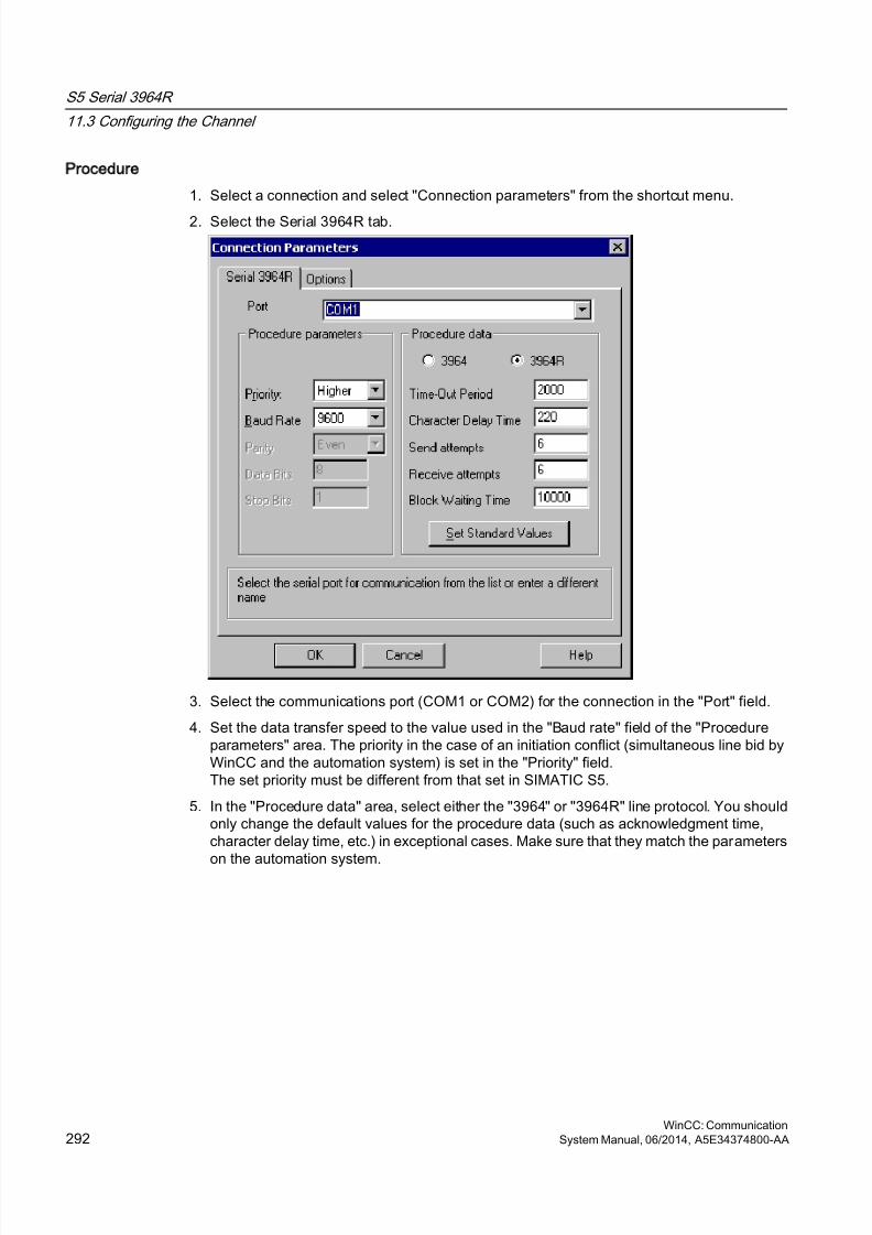
8/20/2019 WinCC Communication en-US en-US
http://slidepdf.com/reader/full/wincc-communication-en-us-en-us 292/527
Procedure
1. Select a connection and select "Connection parameters" from the shortcut menu.
2. Select the Serial 3964R tab.
3. Select the communications port (COM1 or COM2) for the connection in the "Port" field.
4. Set the data transfer speed to the value used in the "Baud rate" field of the "Procedureparameters" area. The priority in the case of an initiation conflict (simultaneous line bid byWinCC and the automation system) is set in the "Priority" field.The set priority must be different from that set in SIMATIC S5.
5. In the "Procedure data" area, select either the "3964" or "3964R" line protocol. You shouldonly change the default values for the procedure data (such as acknowledgment time,character delay time, etc.) in exceptional cases. Make sure that they match the parameters
on the automation system.
S5 Serial 3964R
11.3 Configuring the Channel
WinCC: Communication292 System Manual, 06/2014, A5E34374800-AA
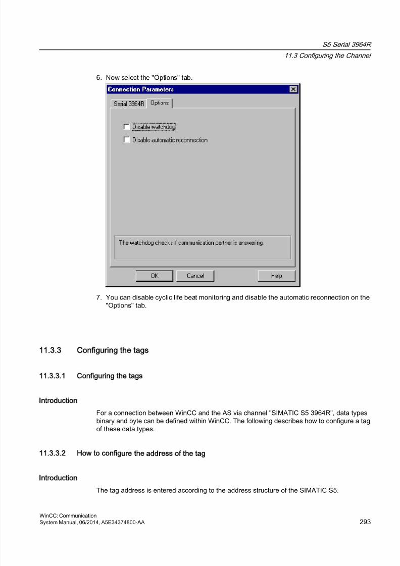
8/20/2019 WinCC Communication en-US en-US
http://slidepdf.com/reader/full/wincc-communication-en-us-en-us 293/527
6. Now select the "Options" tab.
7. You can disable cyclic life beat monitoring and disable the automatic reconnection on the"Options" tab.
11.3.3 Configuring the tags
11.3.3.1 Configuring the tags
Introduction
For a connection between WinCC and the AS via channel "SIMATIC S5 3964R", data typesbinary and byte can be defined within WinCC. The following describes how to configure a tagof these data types.
11.3.3.2 How to configure the address of the tag
Introduction
The tag address is entered according to the address structure of the SIMATIC S5.
S5 Serial 3964R
11.3 Configuring the Channel
WinCC: CommunicationSystem Manual, 06/2014, A5E34374800-AA 293
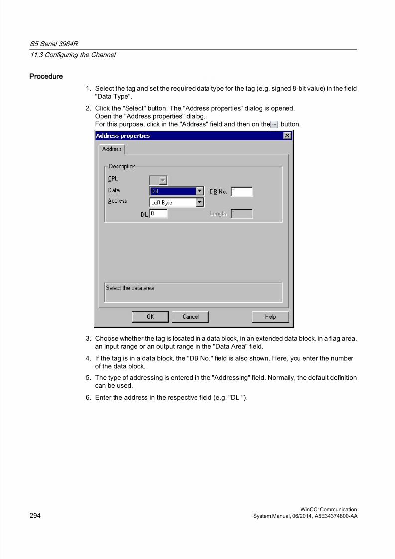
8/20/2019 WinCC Communication en-US en-US
http://slidepdf.com/reader/full/wincc-communication-en-us-en-us 294/527
Procedure
1. Select the tag and set the required data type for the tag (e.g. signed 8-bit value) in the field
"Data Type".2. Click the "Select" button. The "Address properties" dialog is opened.
Open the "Address properties" dialog.For this purpose, click in the "Address" field and then on the button.
3. Choose whether the tag is located in a data block, in an extended data block, in a flag area,an input range or an output range in the "Data Area" field.
4. If the tag is in a data block, the "DB No." field is also shown. Here, you enter the numberof the data block.
5. The type of addressing is entered in the "Addressing" field. Normally, the default definitioncan be used.
6. Enter the address in the respective field (e.g. "DL ").
S5 Serial 3964R
11.3 Configuring the Channel
WinCC: Communication294 System Manual, 06/2014, A5E34374800-AA
8/20/2019 WinCC Communication en-US en-US
http://slidepdf.com/reader/full/wincc-communication-en-us-en-us 295/527
Note
Only read access is possible to the Inputs, Outputs, Timers and Counters address areas.Read and write access is possible to data blocks (DB, DX).
Do not use data word addresses which are greater than 255. Due to a system characteristicof the RK512, only data word addresses 0 to 255 are permissible.It is possible to configure larger addresses, but this leads to data corruption on all configuredtags of this connection.
Frequently, the memory in the PLC can only be accessed by byte or word. When using binaryand "8 Bit" tags, dialog "Bit-Byte-tag" is opened in addition to dialog "Address properties" andthis can be used to change individual bits in the memory of the PLC as well. For this purpose,the addressed memory area is read from the PLC for every single write request and thecorresponding bits and/or bytes are modified. Afterwards, the data is written back to the PLC'smemory.
Note
Changes that have been made by the PLC in a read data area are overwritten when writingback into the data area.
Depending on the type of tag, you can access the automation system's memory bit-wise orbyte-wise.
11.3.3.3 How to configure a tag with bit-wise access
Procedure
1. Select the tag and set the "Binary tag" data type in the "Data Type" field.
2. Open the "Address properties" dialog.
For this purpose, click in the "Address" field and then on the button.
3. Click the "Select" button. The "Bit/Byte tag" dialog is opened.
S5 Serial 3964R
11.3 Configuring the Channel
WinCC: CommunicationSystem Manual, 06/2014, A5E34374800-AA 295
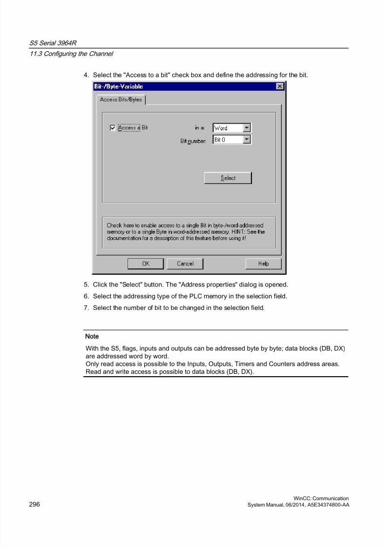
8/20/2019 WinCC Communication en-US en-US
http://slidepdf.com/reader/full/wincc-communication-en-us-en-us 296/527
4. Select the "Access to a bit" check box and define the addressing for the bit.
5. Click the "Select" button. The "Address properties" dialog is opened.6. Select the addressing type of the PLC memory in the selection field.
7. Select the number of bit to be changed in the selection field.
Note
With the S5, flags, inputs and outputs can be addressed byte by byte; data blocks (DB, DX)are addressed word by word.Only read access is possible to the Inputs, Outputs, Timers and Counters address areas.Read and write access is possible to data blocks (DB, DX).
S5 Serial 3964R
11.3 Configuring the Channel
WinCC: Communication296 System Manual, 06/2014, A5E34374800-AA
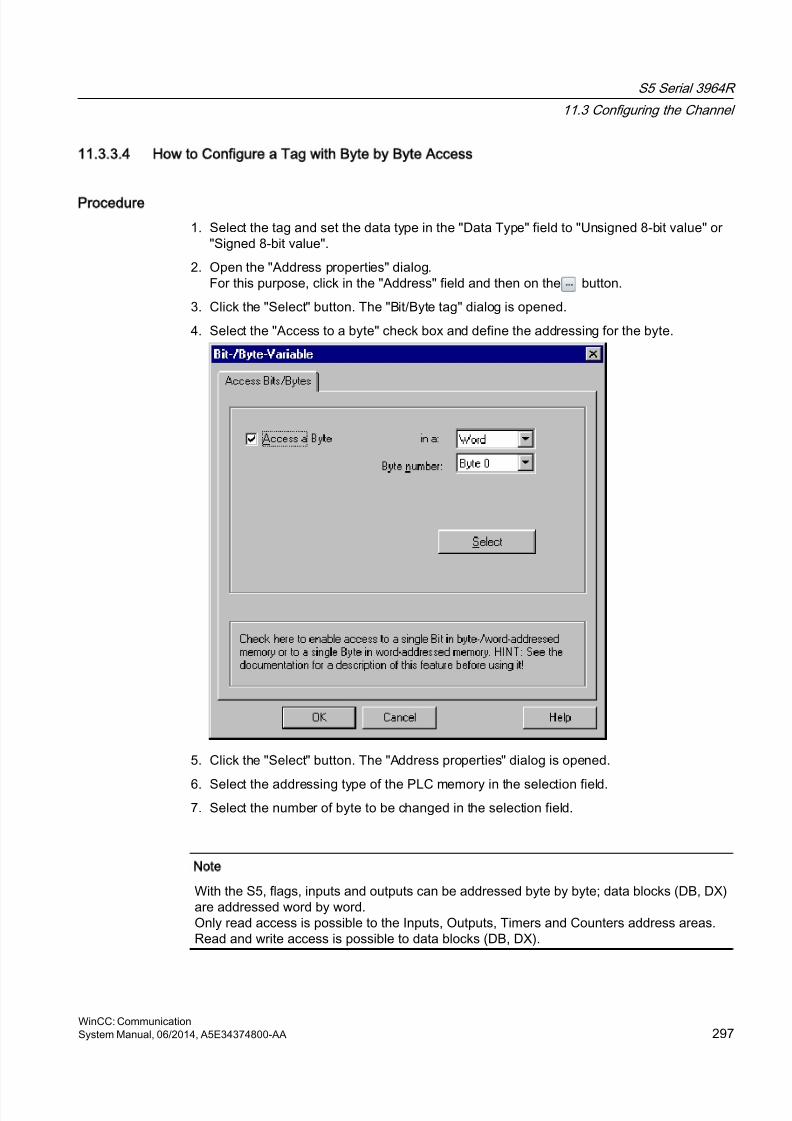
8/20/2019 WinCC Communication en-US en-US
http://slidepdf.com/reader/full/wincc-communication-en-us-en-us 297/527
11.3.3.4 How to Configure a Tag with Byte by Byte Access
Procedure
1. Select the tag and set the data type in the "Data Type" field to "Unsigned 8-bit value" or"Signed 8-bit value".
2. Open the "Address properties" dialog.For this purpose, click in the "Address" field and then on the button.
3. Click the "Select" button. The "Bit/Byte tag" dialog is opened.
4. Select the "Access to a byte" check box and define the addressing for the byte.
5. Click the "Select" button. The "Address properties" dialog is opened.
6. Select the addressing type of the PLC memory in the selection field.7. Select the number of byte to be changed in the selection field.
Note
With the S5, flags, inputs and outputs can be addressed byte by byte; data blocks (DB, DX)are addressed word by word.Only read access is possible to the Inputs, Outputs, Timers and Counters address areas.Read and write access is possible to data blocks (DB, DX).
S5 Serial 3964R
11.3 Configuring the Channel
WinCC: CommunicationSystem Manual, 06/2014, A5E34374800-AA 297

8/20/2019 WinCC Communication en-US en-US
http://slidepdf.com/reader/full/wincc-communication-en-us-en-us 298/527
8/20/2019 WinCC Communication en-US en-US
http://slidepdf.com/reader/full/wincc-communication-en-us-en-us 299/527
SIMATIC S7 Protocol Suite
12
12.1 SIMATIC S7 Protocol Suite Channel
Content
The "SIMATIC S7 Protocol Suite" channel supports communication between a WinCC stationand the SIMATIC S7 automation systems. The suite supports a variety of protocols and typesof networks.
This section shows you
● how to configure various connections and tags for the channel
● how to create a sample project
● how to use the channel's special functions such as the AR_SEND function, raw data tagsand software redundancy
WinCC: CommunicationSystem Manual, 06/2014, A5E34374800-AA 299

8/20/2019 WinCC Communication en-US en-US
http://slidepdf.com/reader/full/wincc-communication-en-us-en-us 300/527
12.2 WinCC Channel SIMATIC S7 Protocol Suite
Function principle
The Channel "SIMATIC S7 Protocol Suite" is used to link SIMATIC S7-300 and SIMATICS7-400 automation systems.
Depending on the communication hardware used, the system supports connections via thefollowing channel units:
● Industrial Ethernet and Industrial Ethernet (II): For communication via a communicationprocessor (such as CP 1612; CP1613) with SIMATIC NET Industrial Ethernet.
● MPI: For communication via the external MPI port of a programming device (e.g. PG 760/PC RI45), via an MPI communications processor or a communications module (e.g. CP5511, CP 5613).
● Named Connections: to communicate with STEP 7 via a symbolic connection. Thesesymbolic connections are configured using STEP 7 and are needed e.g. to provide high-availability communication with the PLC S7-400 in conjunction with the redundancy in H/Fsystems.
● PROFIBUS and PROFIBUS (II): For communication via a communication processor (suchas CP 5613) with SIMATIC NET PROFIBUS.
● Slot-PLC: to communicate with a Slot PLC (e.g. WinAC Pro) that is installed as a PC cardin the WinCC computer.
● Soft-PLC: to communicate with a Software PLC (e.g. WinAC Basis), that is installed as anapplication on the WinCC computer.
● TCP/IP: to communicate with networks using the TCP/IP protocol.
For more information regarding the diagnosis of channels and tags, refer to "CommunicationDiagnostics".
Detailed procedures
Additional information and detailed examples of channel configuration can be found in the"WinCC V6 Communication Manual":
● http://support.automation.siemens.com/WW/view/en/21320307 (http://support.automation.siemens.com/WW/view/en/21320307)
For more information regarding diagnostics of channels and tags, refer to the "WinCC V7.2:Communication" manual, "Communication - Diagnostics":
● http://support.automation.siemens.com/WW/view/en/73568736 (http://support.automation.siemens.com/WW/view/en/73568736)
See also
Software Redundancy - Connection-specific internal tags (Page 379)
"SIMATIC S7 Protocol Suite" Channel - Configuration (Page 307)
SIMATIC S7 Protocol Suite
12.2 WinCC Channel "SIMATIC S7 Protocol Suite"
WinCC: Communication300 System Manual, 06/2014, A5E34374800-AA

8/20/2019 WinCC Communication en-US en-US
http://slidepdf.com/reader/full/wincc-communication-en-us-en-us 301/527
Overview of the supported data types (Page 306)
Channel unit selection (Page 302)
Diagnosis of Channels and Tags (Page 463)
http://support.automation.siemens.com/WW/view/en/21320307 (http://support.automation.siemens.com/WW/view/en/21320307)
http://support.automation.siemens.com/WW/view/en/73568736 (http://support.automation.siemens.com/WW/view/en/73568736)
SIMATIC S7 Protocol Suite
12.2 WinCC Channel "SIMATIC S7 Protocol Suite"
WinCC: CommunicationSystem Manual, 06/2014, A5E34374800-AA 301
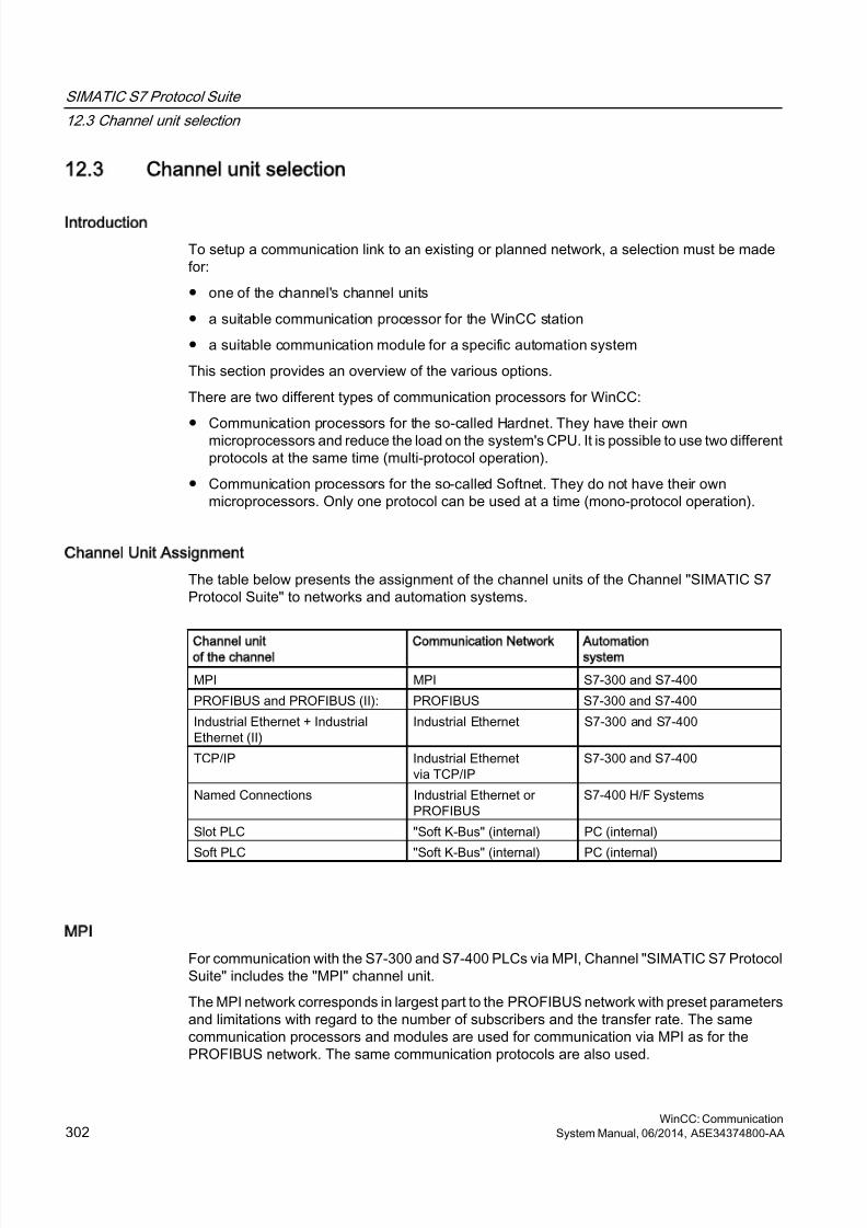
8/20/2019 WinCC Communication en-US en-US
http://slidepdf.com/reader/full/wincc-communication-en-us-en-us 302/527
12.3 Channel unit selection
Introduction
To setup a communication link to an existing or planned network, a selection must be madefor:
● one of the channel's channel units
● a suitable communication processor for the WinCC station
● a suitable communication module for a specific automation system
This section provides an overview of the various options.
There are two different types of communication processors for WinCC:
● Communication processors for the so-called Hardnet. They have their ownmicroprocessors and reduce the load on the system's CPU. It is possible to use two differentprotocols at the same time (multi-protocol operation).
● Communication processors for the so-called Softnet. They do not have their ownmicroprocessors. Only one protocol can be used at a time (mono-protocol operation).
Channel Unit Assignment
The table below presents the assignment of the channel units of the Channel "SIMATIC S7Protocol Suite" to networks and automation systems.
Channel unit
of the channel
Communication Network
Automation
system
MPI MPI S7-300 and S7-400
PROFIBUS and PROFIBUS (II): PROFIBUS S7-300 and S7-400
Industrial Ethernet + IndustrialEthernet (II)
Industrial Ethernet S7-300 and S7-400
TCP/IP Industrial Ethernetvia TCP/IP
S7-300 and S7-400
Named Connections Industrial Ethernet or PROFIBUS
S7-400 H/F Systems
Slot PLC "Soft K-Bus" (internal) PC (internal)
Soft PLC "Soft K-Bus" (internal) PC (internal)
MPI
For communication with the S7-300 and S7-400 PLCs via MPI, Channel "SIMATIC S7 ProtocolSuite" includes the "MPI" channel unit.
The MPI network corresponds in largest part to the PROFIBUS network with preset parametersand limitations with regard to the number of subscribers and the transfer rate. The samecommunication processors and modules are used for communication via MPI as for thePROFIBUS network. The same communication protocols are also used.
SIMATIC S7 Protocol Suite
12.3 Channel unit selection
WinCC: Communication302 System Manual, 06/2014, A5E34374800-AA
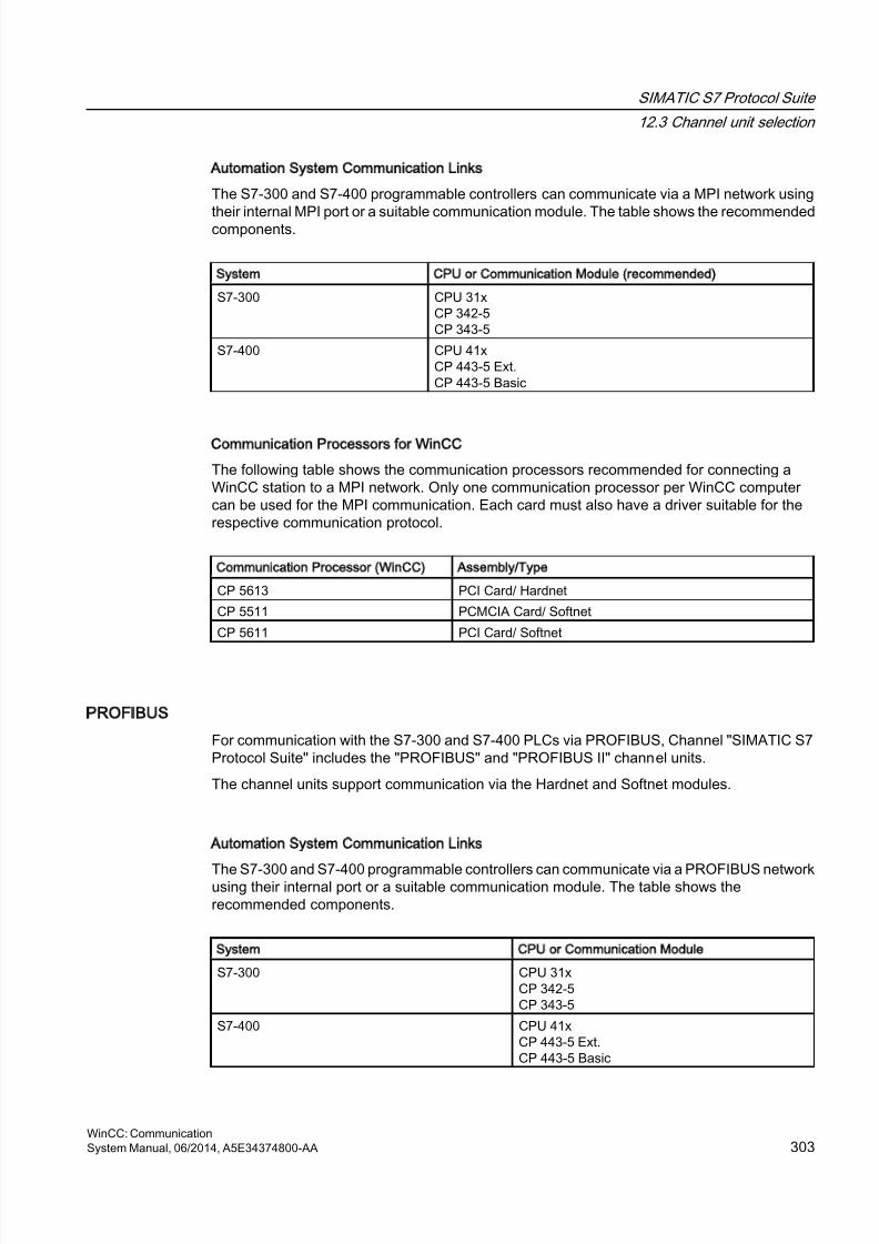
8/20/2019 WinCC Communication en-US en-US
http://slidepdf.com/reader/full/wincc-communication-en-us-en-us 303/527
Automation System Communication Links
The S7-300 and S7-400 programmable controllers can communicate via a MPI network using
their internal MPI port or a suitable communication module. The table shows the recommendedcomponents.
System CPU or Communication Module (recommended)
S7-300 CPU 31xCP 342-5CP 343-5
S7-400 CPU 41xCP 443-5 Ext.CP 443-5 Basic
Communication Processors for WinCC
The following table shows the communication processors recommended for connecting aWinCC station to a MPI network. Only one communication processor per WinCC computercan be used for the MPI communication. Each card must also have a driver suitable for therespective communication protocol.
Communication Processor (WinCC) Assembly/Type
CP 5613 PCI Card/ Hardnet
CP 5511 PCMCIA Card/ Softnet
CP 5611 PCI Card/ Softnet
PROFIBUS
For communication with the S7-300 and S7-400 PLCs via PROFIBUS, Channel "SIMATIC S7Protocol Suite" includes the "PROFIBUS" and "PROFIBUS II" channel units.
The channel units support communication via the Hardnet and Softnet modules.
Automation System Communication Links
The S7-300 and S7-400 programmable controllers can communicate via a PROFIBUS networkusing their internal port or a suitable communication module. The table shows therecommended components.
System CPU or Communication Module
S7-300 CPU 31xCP 342-5CP 343-5
S7-400 CPU 41xCP 443-5 Ext.CP 443-5 Basic
SIMATIC S7 Protocol Suite
12.3 Channel unit selection
WinCC: CommunicationSystem Manual, 06/2014, A5E34374800-AA 303
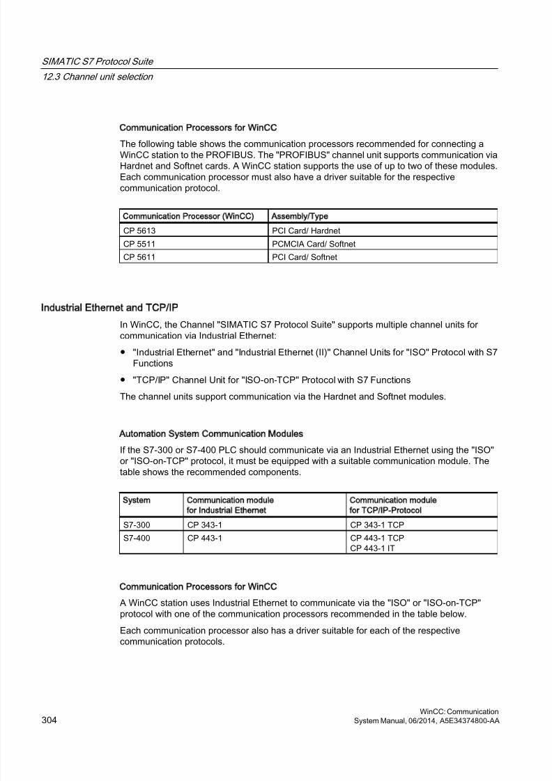
8/20/2019 WinCC Communication en-US en-US
http://slidepdf.com/reader/full/wincc-communication-en-us-en-us 304/527
Communication Processors for WinCC
The following table shows the communication processors recommended for connecting aWinCC station to the PROFIBUS. The "PROFIBUS" channel unit supports communication viaHardnet and Softnet cards. A WinCC station supports the use of up to two of these modules.Each communication processor must also have a driver suitable for the respectivecommunication protocol.
Communication Processor (WinCC) Assembly/Type
CP 5613 PCI Card/ Hardnet
CP 5511 PCMCIA Card/ Softnet
CP 5611 PCI Card/ Softnet
Industrial Ethernet and TCP/IP
In WinCC, the Channel "SIMATIC S7 Protocol Suite" supports multiple channel units forcommunication via Industrial Ethernet:
● "Industrial Ethernet" and "Industrial Ethernet (II)" Channel Units for "ISO" Protocol with S7Functions
● "TCP/IP" Channel Unit for "ISO-on-TCP" Protocol with S7 Functions
The channel units support communication via the Hardnet and Softnet modules.
Automation System Communication Modules
If the S7-300 or S7-400 PLC should communicate via an Industrial Ethernet using the "ISO"or "ISO-on-TCP" protocol, it must be equipped with a suitable communication module. Thetable shows the recommended components.
System Communication module
for Industrial Ethernet
Communication module
for TCP/IP-Protocol
S7-300 CP 343-1 CP 343-1 TCP
S7-400 CP 443-1 CP 443-1 TCP
CP 443-1 IT
Communication Processors for WinCC
A WinCC station uses Industrial Ethernet to communicate via the "ISO" or "ISO-on-TCP"protocol with one of the communication processors recommended in the table below.
Each communication processor also has a driver suitable for each of the respectivecommunication protocols.
SIMATIC S7 Protocol Suite
12.3 Channel unit selection
WinCC: Communication304 System Manual, 06/2014, A5E34374800-AA

8/20/2019 WinCC Communication en-US en-US
http://slidepdf.com/reader/full/wincc-communication-en-us-en-us 305/527
Communication Processor (WinCC) Assembly/Type
CP 1612 PCI Card/ Softnet
CP 1613 PCI Card/ HardnetCP 1512 PCMCIA Card/ Softnet
SIMATIC S7 Protocol Suite
12.3 Channel unit selection
WinCC: CommunicationSystem Manual, 06/2014, A5E34374800-AA 305

8/20/2019 WinCC Communication en-US en-US
http://slidepdf.com/reader/full/wincc-communication-en-us-en-us 306/527
12.4 Overview of the supported data types
Introduction
For configuring a tag, you need to define data type and type conversion according to the dataformat in AS.
The table shows the data types supported by the channel and the use of type conversions.
Supported data types
Data Types Type conversion
Binary tag No
Signed 8-bit value YesUnsigned 8-bit value Yes
Signed 16-bit value Yes
Unsigned 16-bit value Yes
Signed 32-bit value Yes
Unsigned 32-bit value Yes
Floating-point number 32-bit IEEE 754 Yes
Text tag, 8-bit font No
Raw data type No
You will find additional information about type conversion in the "Communication" section.
SIMATIC S7 Protocol Suite
12.4 Overview of the supported data types
WinCC: Communication306 System Manual, 06/2014, A5E34374800-AA

8/20/2019 WinCC Communication en-US en-US
http://slidepdf.com/reader/full/wincc-communication-en-us-en-us 307/527
12.5 Configuring the Channel
12.5.1 SIMATIC S7 Protocol Suite Channel - Configuration
Introduction
This section will show you how to configure the "SIMATIC S7 Protocol Suite" channel.
1. Installing the Channel
2. Channel unit selection
3. Configuring a connection
4. Tag configurationSystem parameter configuration
Further information regarding the diagnosis of the channel, connection and tags can be foundunder "Communication Diagnosis".
See also
System Parameters of the Channel Unit (Page 331)
Configuring the tags (Page 325)
Channel units of the "SIMATIC S7 Protocol Suite" channel (Page 308)
Diagnosis of Channels and Tags (Page 463)
12.5.2 How to configure the SIMATIC S7 Protocol Suite channel
Introduction
This section will show you how to install the "SIMATIC S7 Protocol Suite" channel.
1. Installing the Channel
2. Channel unit selection3. Creating a connection
4. Inserting a tag
5. Configuring the system parameters in a customized WinCC installation
Prerequisites:
● The communication module is built in.
● The hardware driver has been installed.
● Cable connection to AS exists.
SIMATIC S7 Protocol Suite
12.5 Configuring the Channel
WinCC: CommunicationSystem Manual, 06/2014, A5E34374800-AA 307

8/20/2019 WinCC Communication en-US en-US
http://slidepdf.com/reader/full/wincc-communication-en-us-en-us 308/527
Procedure
1. In the navigation area of the tag management, select the entry "Add new driver" in the
shortcut menu of node "Tag Management".2. Select the driver "SIMATIC S7 Protocol Suite". The channel is set up and the
communication driver is displayed in the tag management along with the channel units.
3. Select the desired channel unit and select the "New Connection" entry in the shortcut menu.
4. Enter the name of the connection.
5. Click the "Tags" tab below the table area.
6. Click in the top free cell of the "Name" column.Enter the name for the tag.
7. Select the desired data type in the "Data Type" field.You have the option of defining a start value and a substitute value for the tags in the"Properties" area.For a detailed description of configuring the tags for connecting a specific channel unit,close the dialog and continue with the topic "Configuring tags" within the respective channelunit.
8. Open the "Address properties" dialog.For this purpose, click in the "Address" field and then on the button.
9. Close both of the dialogs by clicking the "OK" button.
10.If your WinCC system and the communication hardware is non-standard, you also need toset the system parameters to the non-standard values. Additional information on this topicmay be found under "System parameters".
12.5.3 Channel units
12.5.3.1 Channel units of the SIMATIC S7 Protocol Suite channel
Introduction
The following chapters describe how to configure the channel units and a correspondingconnection. There can be multiple connections in the same channel unit.
See also
"TCP/IP" channel unit (Page 322)
"Soft PLC" channel unit (Page 321)
"Slot PLC" channel unit (Page 319)
Channel Units "PROFIBUS (I + II)" (Page 317)
"Named Connections" channel unit (Page 314)
SIMATIC S7 Protocol Suite
12.5 Configuring the Channel
WinCC: Communication308 System Manual, 06/2014, A5E34374800-AA
8/20/2019 WinCC Communication en-US en-US
http://slidepdf.com/reader/full/wincc-communication-en-us-en-us 309/527
"MPI" channel unit (Page 312)
Channel Units "Industrial Ethernet" + "Industrial Ethernet (II)" (Page 309)
12.5.3.2 Industrial Ethernet (I+II) channel units
Channel Units Industrial Ethernet + Industrial Ethernet (II)
Principle of Operation
The channel unit "Industrial Ethernet" is used to connect WinCC to the S7 automation systemsvia the Industrial Ethernet. Communication is possible via the communications modules (CP),e.g. in the case of automation system S7-300 via CP 343-1 and in the case of S7-400 via CP
443-1.In WinCC different communications processors can be used, e.g. CP 1613. Via the channelunit "Industrial Ethernet (II)" a second communications processor can be addressed. Becausecommunication takes place via the "ISO" transport protocol, it is not necessary to configurethe logical connection in the local database.
The function and configurations regarding these channel units are identical.
Typical unit terminology
Communications processor
A communications processor (CP) is a module that supports communication between theWinCC computer and a specific network.
ISO transport protocol
ISO transport is a layer of the ISO-OSI reference model and offers services related to thetransfer of data via connections. The transport layer handles data flow control, blocking andacknowledgment tasks.
The protocol defines the structure of the data traffic with regards to content on the physicalline. It defines, among other things, the mode of operation, the procedure when establishinga connection, data backup or the transmission speed.
Industrial Ethernet
The Industrial Ethernet is the most efficient subnet in the industrial environment. It is suitablefor the factory and cell levels and facilitates the exchange of large data volumes over largedistances between a large number of participants.
The Industrial Ethernet is an open communications network and is standardized in accordancewith IEEE 802.3. Its prime advantages are its speed, simple extendibility and openness as wellas high availability and worldwide utilization. The configuration process requires a minimumof effort.
SIMATIC S7 Protocol Suite
12.5 Configuring the Channel
WinCC: CommunicationSystem Manual, 06/2014, A5E34374800-AA 309
8/20/2019 WinCC Communication en-US en-US
http://slidepdf.com/reader/full/wincc-communication-en-us-en-us 310/527
See also
Configuring the tags (Page 325)
How to configure a "Industrial Ethernet" channel unit connection (Page 310)
How to configure a Industrial Ethernet channel unit connection
Introduction
In addition to the channel unit, WinCC also requires a logical connection to communicate withthe PLC. All the specific parameters are defined while establishing a logical connection.
For S7 automation systems, a communications module, e.g. a CP 343-1 in the S7-300 or aCP 443-1 in the S7-400, is used for the communication.
A communications processor, for example CP 1613, is used in WinCC. A secondcommunications processor can be addressed/increased via the "Industrial Ethernet II" channelunit.
Further information regarding the diagnostics of the channel, connection and tags can be foundunder "Communication Diagnostics".
Requirements
● The Channel "SIMATIC S7 Protocol Suite" must be integrated into the project.
Procedure
1. Select the entry "New Connection" in the shortcut menu of the channel unit "IndustrialEthernet".A new connection is created.
2. Enter a connection name, for example, "Test_Ind_Eth".
SIMATIC S7 Protocol Suite
12.5 Configuring the Channel
WinCC: Communication310 System Manual, 06/2014, A5E34374800-AA
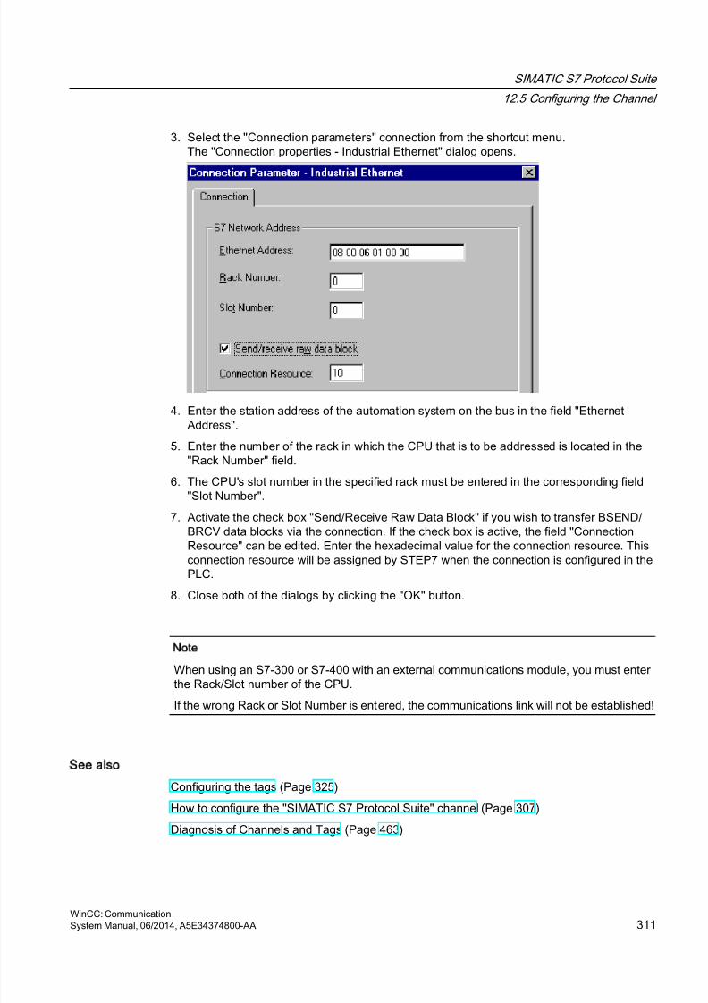
8/20/2019 WinCC Communication en-US en-US
http://slidepdf.com/reader/full/wincc-communication-en-us-en-us 311/527
3. Select the "Connection parameters" connection from the shortcut menu.The "Connection properties - Industrial Ethernet" dialog opens.
4. Enter the station address of the automation system on the bus in the field "EthernetAddress".
5. Enter the number of the rack in which the CPU that is to be addressed is located in the"Rack Number" field.
6. The CPU's slot number in the specified rack must be entered in the corresponding field"Slot Number".
7. Activate the check box "Send/Receive Raw Data Block" if you wish to transfer BSEND/
BRCV data blocks via the connection. If the check box is active, the field "ConnectionResource" can be edited. Enter the hexadecimal value for the connection resource. Thisconnection resource will be assigned by STEP7 when the connection is configured in thePLC.
8. Close both of the dialogs by clicking the "OK" button.
Note
When using an S7-300 or S7-400 with an external communications module, you must enterthe Rack/Slot number of the CPU.
If the wrong Rack or Slot Number is entered, the communications link will not be established!
See also
Configuring the tags (Page 325)
How to configure the "SIMATIC S7 Protocol Suite" channel (Page 307)
Diagnosis of Channels and Tags (Page 463)
SIMATIC S7 Protocol Suite
12.5 Configuring the Channel
WinCC: CommunicationSystem Manual, 06/2014, A5E34374800-AA 311
8/20/2019 WinCC Communication en-US en-US
http://slidepdf.com/reader/full/wincc-communication-en-us-en-us 312/527
12.5.3.3 MPI channel unit
MPI channel unit
Principle of Operation
The MPI channel unit is used to connect WinCC to the SIMATIC S7-300 and S7-400automation systems via MPI.
This can be done in WinCC via
● the internal MPI interface of the programming devices such as PG 760/PC RI45
● a communication processor such as CP 5613 (PCI card)
The so-called MPI module (ISA card) is also suitable - it exists but is hard to get. It was replacedby the communication processors.
In PLC, linking is done via the MPI interface of the CPU or a corresponding communicationmodule.
Typical unit terminology
MPI
MPI means Multi Point Interface and is a communication link where there can be multipleparticipants. The connection to the communication network takes place as follows:
● In PLC via the MPI interface of the CPU or a communication module,
● In WinCC via the built-in MPI interface, for e.g., of a programming device or acommunication processor (network card).
Communications processor
A communications processor (CP) is a module that supports communication between theWinCC computer and a specific network.
See also
Configuring the tags (Page 325)
How to configure a "MPI" channel unit connection (Page 312)
How to configure a MPI channel unit connection
Introduction
In addition to the channel unit, WinCC also requires a logical connection to communicate withthe PLC. All the specific parameters are defined while establishing a logical connection.
S7-300 and S7-400 PLCs either use the internal MPI interface or a communication modulesuch as CP 342-5 (SIMATIC S7-300) or CP 443-5 (SIMATIC S7-400).
SIMATIC S7 Protocol Suite
12.5 Configuring the Channel
WinCC: Communication312 System Manual, 06/2014, A5E34374800-AA
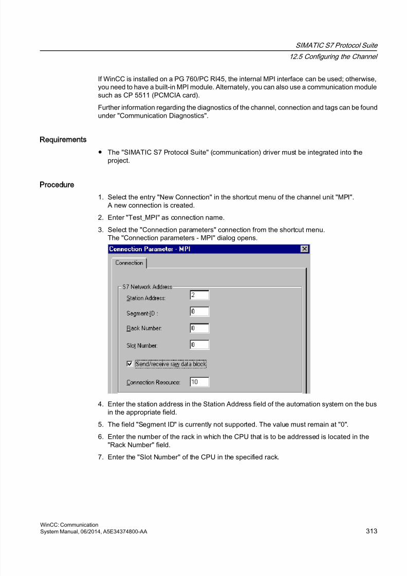
8/20/2019 WinCC Communication en-US en-US
http://slidepdf.com/reader/full/wincc-communication-en-us-en-us 313/527
If WinCC is installed on a PG 760/PC RI45, the internal MPI interface can be used; otherwise,you need to have a built-in MPI module. Alternately, you can also use a communication modulesuch as CP 5511 (PCMCIA card).
Further information regarding the diagnostics of the channel, connection and tags can be foundunder "Communication Diagnostics".
Requirements
● The "SIMATIC S7 Protocol Suite" (communication) driver must be integrated into theproject.
Procedure
1. Select the entry "New Connection" in the shortcut menu of the channel unit "MPI".A new connection is created.
2. Enter "Test_MPI" as connection name.
3. Select the "Connection parameters" connection from the shortcut menu.The "Connection parameters - MPI" dialog opens.
4. Enter the station address in the Station Address field of the automation system on the busin the appropriate field.
5. The field "Segment ID" is currently not supported. The value must remain at "0".
6. Enter the number of the rack in which the CPU that is to be addressed is located in the"Rack Number" field.
7. Enter the "Slot Number" of the CPU in the specified rack.
SIMATIC S7 Protocol Suite
12.5 Configuring the Channel
WinCC: CommunicationSystem Manual, 06/2014, A5E34374800-AA 313
8/20/2019 WinCC Communication en-US en-US
http://slidepdf.com/reader/full/wincc-communication-en-us-en-us 314/527
8. Activate the check box "Send/Receive Raw Data Block" if you wish to transfer BSEND/BRCV data blocks via the connection. If the check box is flagged, the field "ConnectionResource" will also be active. Enter the hexadecimal value for the connection resource.
This connection resource will be assigned by STEP7 when the connection is configured inthe PLC.
9. Close both of the dialogs by clicking the "OK" button.
Note
When using an S7-300 or S7-400 with an external communications processor, you must enterthe Rack/Slot number of the CPU.
If the wrong Rack or Slot Number is entered, the communications link will not be established!
While using a S7-300, for the link via the internal MPI interface of the CPU, the rack/ slotnumber = 0 must be given.
See also
Configuring the tags (Page 325)
How to configure the "SIMATIC S7 Protocol Suite" channel (Page 307)
12.5.3.4 Named Connections channel unit
Named Connections channel unit
Principle of Operation
This channel unit is used for setting up a symbolic connection configured using STEP 7. WinCCcan thus access redundant and non-redundant connection via a symbolic connection name.The symbolic connections are required, for e.g., for high availability communication usingS7-400 PLC in connection with redundancy in H/F systems.
The symbolic connection names are configured in STEP 7 using the NETPRO application.The connection names, connection parameters and the application names are stored in a
database (*.XDB). This databased is automatically stored by the PLC/OS Engineering Tool"Mapper" in the corresponding WinCC project directory; however, it can also be copied outsidethis directory, for e.g. if you are not using the "Mapper".
Note
There should only be one XDB file per communication participant in the WinCC system.Hence, a XDB file should not be copied and used on multiple WinCC computers.
You have the following options to activate this database in WinCC:
SIMATIC S7 Protocol Suite
12.5 Configuring the Channel
WinCC: Communication314 System Manual, 06/2014, A5E34374800-AA

8/20/2019 WinCC Communication en-US en-US
http://slidepdf.com/reader/full/wincc-communication-en-us-en-us 315/527
● If the XDB file is located outside the project directory (for e.g. because the Mapper tool isnot used), you need to enter the path and name of the XDB file in the "Set PG/PC interface"(Control Panel) in the STEP 7 Configuration tab before starting WinCC.
On starting WinCC, this XDB file is read from this external directory provided no file existswithin the project directory. This procedure is helpful when multiple projects have to use thesame centrally stored database.
● If the Mapper tool is used, it automatically copies the XDB file to the WinCC project directory.On starting WinCC and opening the project, the data is read from the S7 channel andentered in the registration database of Windows.
Thereafter, a connection can be configured in WinCC by assigning one of the symbolicconnection names to the selected application name.
Note
The application and connection name can also be entered manually, for e.g. if an XDB filedoes not exist for the symbolic connection name or if the project is to be transferred to anothercomputer. It is necessary to check the correct writing of the name in STEP 7 because thereis no name validation in the CS mode.
Typical unit terminology
Communications processor
A communications processor (CP) is a module that supports communication between the PLCand a specific network.
See also
Configuring the tags (Page 325)
How to configure a "Named Connections" channel unit connection (Page 315)
How to configure a Named Connections channel unit connection
Introduction
In addition to the channel unit, WinCC also requires a logical connection to communicate withthe S7-400 PLC via a symbolic connection.
For setting up a logical connection, one of the symbolic connection names listed in the"Connection name" field is assigned to a selected application name.
The symbolic connection names and application names are configured in STEP 7.
Further information regarding the diagnostics of the channel, connection and tags can be foundunder "Communication Diagnostics".
SIMATIC S7 Protocol Suite
12.5 Configuring the Channel
WinCC: CommunicationSystem Manual, 06/2014, A5E34374800-AA 315

8/20/2019 WinCC Communication en-US en-US
http://slidepdf.com/reader/full/wincc-communication-en-us-en-us 316/527
Requirements
● The Channel "SIMATIC S7 Protocol Suite" must be integrated into the project.
Procedure
1. Select the entry "New Connection" in the shortcut menu of the channel unit "NamedConnections".A new connection is created.
2. Enter a connection name, for example, "Test_NC".
3. Select the "Connection parameters" connection from the shortcut menu.The "Connection parameters - Named Connections" dialog opens.
4. In the Application name field, enter the application name that has been configured in STEP
7. Default value is WinCC.5. In the Connection name field, enter the symbolic connection name that has been configured
in STEP 7.
6. Close both of the dialogs by clicking the "OK" button.
Note
The application and connection name can also be entered manually, for e.g. if an XDB filedoes not exist for the symbolic connection name or if the project is to be transferred to anothercomputer. It is necessary to check the correct writing of the name in STEP 7 because thereis no name validation in the CS mode.
See also
Configuring the tags (Page 325)
How to configure the "SIMATIC S7 Protocol Suite" channel (Page 307)
SIMATIC S7 Protocol Suite
12.5 Configuring the Channel
WinCC: Communication316 System Manual, 06/2014, A5E34374800-AA
8/20/2019 WinCC Communication en-US en-US
http://slidepdf.com/reader/full/wincc-communication-en-us-en-us 317/527
12.5.3.5 PROFIBUS (I+II) channel units
Channel Units PROFIBUS (I + II)
Principle of Operation
The channel unit is used to connect WinCC to the SIMATIC S7-300 and S7-400 automationsystems via a PROFIBUS network.
For the S7 automation systems, a communications module is used, e.g. a CP 342-5 in a S7-300or a CP 443-5 in a S7-400.
A communications processor, for example CP 5613, is used in WinCC.
A second communications processor can be addressed via the "PROFIBUS II" channel unit.
In this manner, the maximum number of connections is increased.
Typical unit terminology
PROFIBUS
The PROFIBUS is an open, nonproprietary communications system for the cell and field levelsand has been designed for a maximum of 127 participants. The PROFIBUS is based on theEuropean Standard EN 50170, Volume 2, PROFIBUS. PROFIBUS uses token passing withan underlying master/slave access procedure.
Communications processor
A communications processor (CP) is a module that supports communication between theWinCC computer and a specific network.
See also
Configuring the tags (Page 325)
How to configure a "PROFIBUS" channel unit connection (Page 317)
How to configure a PROFIBUS channel unit connection
Introduction
In addition to the channel unit, WinCC must also have a logical connection to communicatewith the PLC. All the specific parameters are defined while establishing a logical connection.
For S7 automation systems, a communications module is used, e.g. a CP 342-5 in a S7-300or a CP 443-5 in a S7-400.
A communications processor, for example CP 5613, is used in WinCC. A secondcommunications processor can be addressed via the "PROFIBUS II" channel unit.
Further information regarding the diagnostics of the channel, connection and tags can be foundunder "Communication Diagnostics".
SIMATIC S7 Protocol Suite
12.5 Configuring the Channel
WinCC: CommunicationSystem Manual, 06/2014, A5E34374800-AA 317
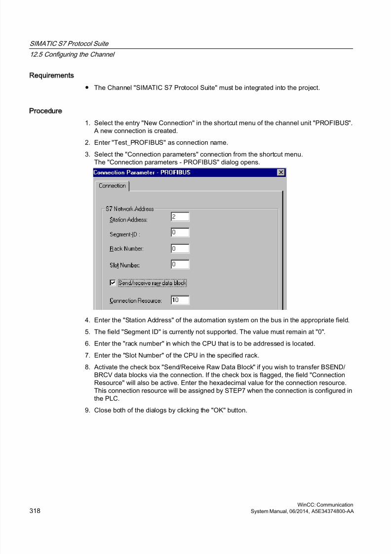
8/20/2019 WinCC Communication en-US en-US
http://slidepdf.com/reader/full/wincc-communication-en-us-en-us 318/527
Requirements
● The Channel "SIMATIC S7 Protocol Suite" must be integrated into the project.
Procedure
1. Select the entry "New Connection" in the shortcut menu of the channel unit "PROFIBUS".A new connection is created.
2. Enter "Test_PROFIBUS" as connection name.
3. Select the "Connection parameters" connection from the shortcut menu.The "Connection parameters - PROFIBUS" dialog opens.
4. Enter the "Station Address" of the automation system on the bus in the appropriate field.
5. The field "Segment ID" is currently not supported. The value must remain at "0".
6. Enter the "rack number" in which the CPU that is to be addressed is located.
7. Enter the "Slot Number" of the CPU in the specified rack.
8. Activate the check box "Send/Receive Raw Data Block" if you wish to transfer BSEND/BRCV data blocks via the connection. If the check box is flagged, the field "ConnectionResource" will also be active. Enter the hexadecimal value for the connection resource.
This connection resource will be assigned by STEP7 when the connection is configured inthe PLC.
9. Close both of the dialogs by clicking the "OK" button.
SIMATIC S7 Protocol Suite
12.5 Configuring the Channel
WinCC: Communication318 System Manual, 06/2014, A5E34374800-AA

8/20/2019 WinCC Communication en-US en-US
http://slidepdf.com/reader/full/wincc-communication-en-us-en-us 319/527
Note
When starting up the PROFIBUS communication, PROFIBUS errors can occur if thecommunication processor was connected to the PROFIBUS while the WinCC computer wasON. Therefore, it is recommended that the computer be switched OFF before connecting itto the PROFIBUS. Otherwise, (in accordance with the PROFIBUS standard) multiple tokensmay be generated on the bus, which will cause a bus error.
When using an S7-300 or S7-400 with an external communications module, you must enterthe Rack/Slot number of the CPU.
If the wrong Rack or Slot Number is entered, the communications link will not be established!
See also
Configuring the tags (Page 325)
How to configure the "SIMATIC S7 Protocol Suite" channel (Page 307)
12.5.3.6 Slot PLC channel unit
Slot PLC channel unit
Principle of Operation
Channel unit "Slot PLC" serves the communication between WinCC and up to four Slot PLC(WinAC Pro) installed in the WinCC computer. Since the Slot PLC has an integrated interface,no additional communication hardware is required for the connection between WinCC and SlotPLC.
See also
Configuring the tags (Page 325)
How to Configure a "Slot PLC" Channel Unit Connection (Page 319)
How to Configure a Slot PLC Channel Unit Connection
Introduction
In order to communicate with the installed SPS cards, WinCC requires a logical connection inaddition to the channel unit. All the specific parameters are defined while establishing a logicalconnection.
SIMATIC S7 Protocol Suite
12.5 Configuring the Channel
WinCC: CommunicationSystem Manual, 06/2014, A5E34374800-AA 319
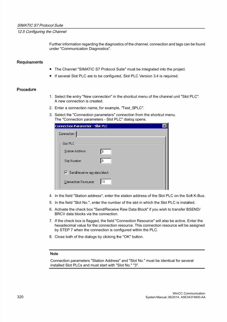
8/20/2019 WinCC Communication en-US en-US
http://slidepdf.com/reader/full/wincc-communication-en-us-en-us 320/527
Further information regarding the diagnostics of the channel, connection and tags can be foundunder "Communication Diagnostics".
Requirements
● The Channel "SIMATIC S7 Protocol Suite" must be integrated into the project.
● If several Slot PLC are to be configured, Slot PLC Version 3.4 is required.
Procedure
1. Select the entry "New connection" in the shortcut menu of the channel unit "Slot PLC".A new connection is created.
2. Enter a connection name, for example, "Test_SPLC".
3. Select the "Connection parameters" connection from the shortcut menu.The "Connection parameters - Slot PLC" dialog opens.
4. In the field "Station address", enter the station address of the Slot PLC on the Soft K-Bus.
5. In the field "Slot No.", enter the number of the slot in which the Slot PLC is installed.
6. Activate the check box "Send/Receive Raw Data Block" if you wish to transfer BSEND/BRCV data blocks via the connection.
7. If the check box is flagged, the field "Connection Resource" will also be active. Enter the
hexadecimal value for the connection resource. This connection resource will be assignedby STEP 7 when the connection is configured within the PLC.
8. Close both of the dialogs by clicking the "OK" button.
Note
Connection parameters "Station Address" and "Slot No." must be identical for severalinstalled Slot PLCs and must start with "Slot No." "3".
SIMATIC S7 Protocol Suite
12.5 Configuring the Channel
WinCC: Communication320 System Manual, 06/2014, A5E34374800-AA
8/20/2019 WinCC Communication en-US en-US
http://slidepdf.com/reader/full/wincc-communication-en-us-en-us 321/527
See also
Configuring the tags (Page 325)
How to configure the "SIMATIC S7 Protocol Suite" channel (Page 307)
12.5.3.7 Soft PLC channel unit
Soft PLC channel unit
Principle of Operation
Channel unit "Slot PLC" serves the communication between WinCC and a Soft PLC (WinAC
Basic) installed in the WinCC computer. No other communication hardware is required forconnecting WinCC to the Soft PLC.
See also
Configuring the tags (Page 325)
How to configure a connection on the "Soft PLC" channel unit (Page 321)
How to configure a connection on the Soft PLC channel unit
Introduction
In addition to the channel unit, WinCC must also have a logical connection to communicatewith the Soft PLC. All the specific parameters are defined while establishing a logicalconnection.
Further information regarding the diagnostics of the channel, connection and tags can be foundunder "Communication Diagnostics".
Requirements
● The Channel "SIMATIC S7 Protocol Suite" must be integrated into the project.
Procedure
1. Select the entry "New connection" in the shortcut menu of the channel unit "Soft PLC".A new connection is created.
2. Enter a connection name, for example, "Test_SOFTPLC".
SIMATIC S7 Protocol Suite
12.5 Configuring the Channel
WinCC: CommunicationSystem Manual, 06/2014, A5E34374800-AA 321
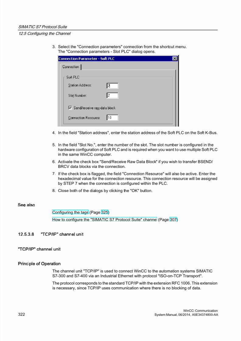
8/20/2019 WinCC Communication en-US en-US
http://slidepdf.com/reader/full/wincc-communication-en-us-en-us 322/527
3. Select the "Connection parameters" connection from the shortcut menu.The "Connection parameters - Slot PLC" dialog opens.
4. In the field "Station address", enter the station address of the Soft PLC on the Soft K-Bus.
5. In the field "Slot No.", enter the number of the slot. The slot number is configured in thehardware configuration of Soft PLC and is required when you want to use multiple Soft PLCin the same WinCC computer.
6. Activate the check box "Send/Receive Raw Data Block" if you wish to transfer BSEND/BRCV data blocks via the connection.
7. If the check box is flagged, the field "Connection Resource" will also be active. Enter the
hexadecimal value for the connection resource. This connection resource will be assignedby STEP 7 when the connection is configured within the PLC.
8. Close both of the dialogs by clicking the "OK" button.
See also
Configuring the tags (Page 325)
How to configure the "SIMATIC S7 Protocol Suite" channel (Page 307)
12.5.3.8 TCP/IP channel unit
TCP/IP channel unit
Principle of Operation
The channel unit "TCP/IP" is used to connect WinCC to the automation systems SIMATICS7-300 and S7-400 via an Industrial Ethernet with protocol "ISO-on-TCP Transport".
The protocol corresponds to the standard TCP/IP with the extension RFC 1006. This extensionis necessary, since TCP/IP uses communication where there is no blocking of data.
SIMATIC S7 Protocol Suite
12.5 Configuring the Channel
WinCC: Communication322 System Manual, 06/2014, A5E34374800-AA
8/20/2019 WinCC Communication en-US en-US
http://slidepdf.com/reader/full/wincc-communication-en-us-en-us 323/527
In the case of the automation system S7-300, communication takes place via acommunications module, e.g. CP 343-1 TCP, and via CP 443-1 TCP or CP 443-1 IT in thecase of S7-400.
In WinCC a communications processor such as CP 1613 is used.
Because communication takes place via the ISO-on-TCP transport protocol, it is not necessaryto configure the logical connection in the local database.
Typical unit terminology
Communications processor
A communications processor (CP) is a module that supports communication between theWinCC computer and a specific network.
ISO transport protocol
ISO transport is a layer of the ISO-OSI reference model and offers services related to thetransfer of data via connections. The transport layer handles data flow control, blocking andacknowledgment tasks.
The protocol defines the structure of the data traffic with regards to content on the physicalline. It defines, among other things, the mode of operation, the procedure when establishinga connection, data backup or the transmission speed.
Industrial Ethernet
The Industrial Ethernet is the most efficient subnet in the industrial environment. It is suitablefor the factory and cell levels and facilitates the exchange of large data volumes over large
distances between a large number of participants.The Industrial Ethernet is an open communications network and is standardized in accordancewith IEEE 802.3. Its prime advantages are its speed, simple extendibility and openness as wellas high availability and worldwide utilization. The configuration process requires a minimumof effort.
See also
Configuring the tags (Page 325)
How to configure a "TCP/IP" channel unit connection (Page 323)
How to configure a TCP/IP channel unit connection
Introduction
In addition to the channel unit, WinCC also requires a logical connection to communicate withthe PLC. All the specific parameters are defined while establishing a logical connection.
In the case of the S7-300 automation system, communication takes place via acommunications module, e.g. CP 343-1 TCP, and via CP 443-1 TCP or CP 443-1 IT in thecase of S7-400.
In WinCC a communications processor such as CP 1613 is used.
SIMATIC S7 Protocol Suite
12.5 Configuring the Channel
WinCC: CommunicationSystem Manual, 06/2014, A5E34374800-AA 323
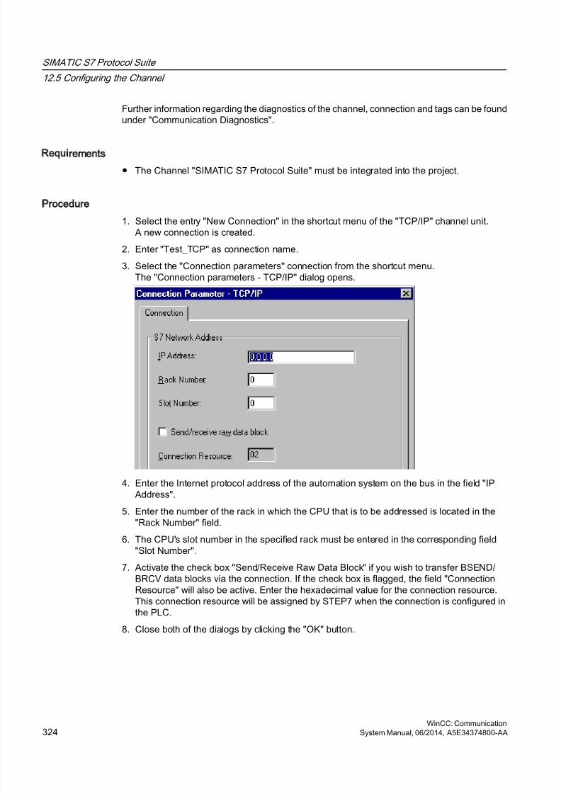
8/20/2019 WinCC Communication en-US en-US
http://slidepdf.com/reader/full/wincc-communication-en-us-en-us 324/527
Further information regarding the diagnostics of the channel, connection and tags can be foundunder "Communication Diagnostics".
Requirements
● The Channel "SIMATIC S7 Protocol Suite" must be integrated into the project.
Procedure
1. Select the entry "New Connection" in the shortcut menu of the "TCP/IP" channel unit.A new connection is created.
2. Enter "Test_TCP" as connection name.
3. Select the "Connection parameters" connection from the shortcut menu.
The "Connection parameters - TCP/IP" dialog opens.
4. Enter the Internet protocol address of the automation system on the bus in the field "IPAddress".
5. Enter the number of the rack in which the CPU that is to be addressed is located in the"Rack Number" field.
6. The CPU's slot number in the specified rack must be entered in the corresponding field"Slot Number".
7. Activate the check box "Send/Receive Raw Data Block" if you wish to transfer BSEND/BRCV data blocks via the connection. If the check box is flagged, the field "ConnectionResource" will also be active. Enter the hexadecimal value for the connection resource.This connection resource will be assigned by STEP7 when the connection is configured inthe PLC.
8. Close both of the dialogs by clicking the "OK" button.
SIMATIC S7 Protocol Suite
12.5 Configuring the Channel
WinCC: Communication324 System Manual, 06/2014, A5E34374800-AA
8/20/2019 WinCC Communication en-US en-US
http://slidepdf.com/reader/full/wincc-communication-en-us-en-us 325/527
Note
When using an S7-300 or S7-400 with an external communications module, you must enterthe Rack/Slot number of the CPU.
If the wrong Rack or Slot Number is entered, the communications link will not be established!
See also
Configuring the tags (Page 325)
How to configure the "SIMATIC S7 Protocol Suite" channel (Page 307)
12.5.4 Configuring the tags
12.5.4.1 Configuring the tags
Introduction
The following sections describe how to configure the tags. It is different in the way the dataarea in the PLC is accessed and the data type of the WinCC tags.
Further information regarding the diagnosis of the channel, connection and tags can be foundunder "Communication Diagnosis".
See also
How to Configure a Text Tag (Page 329)
How to Configure a Tag with Word by Word Access (Page 328)
How to Configure a Tag with Byte by Byte Access (Page 327)
How to Configure a Tag with Bit by Bit Access (Page 325)
12.5.4.2 How to Configure a Tag with Bit by Bit Access
Introduction
This section shows you how to configure a tag for bit by bit access for the address area in PLC.
SIMATIC S7 Protocol Suite
12.5 Configuring the Channel
WinCC: CommunicationSystem Manual, 06/2014, A5E34374800-AA 325
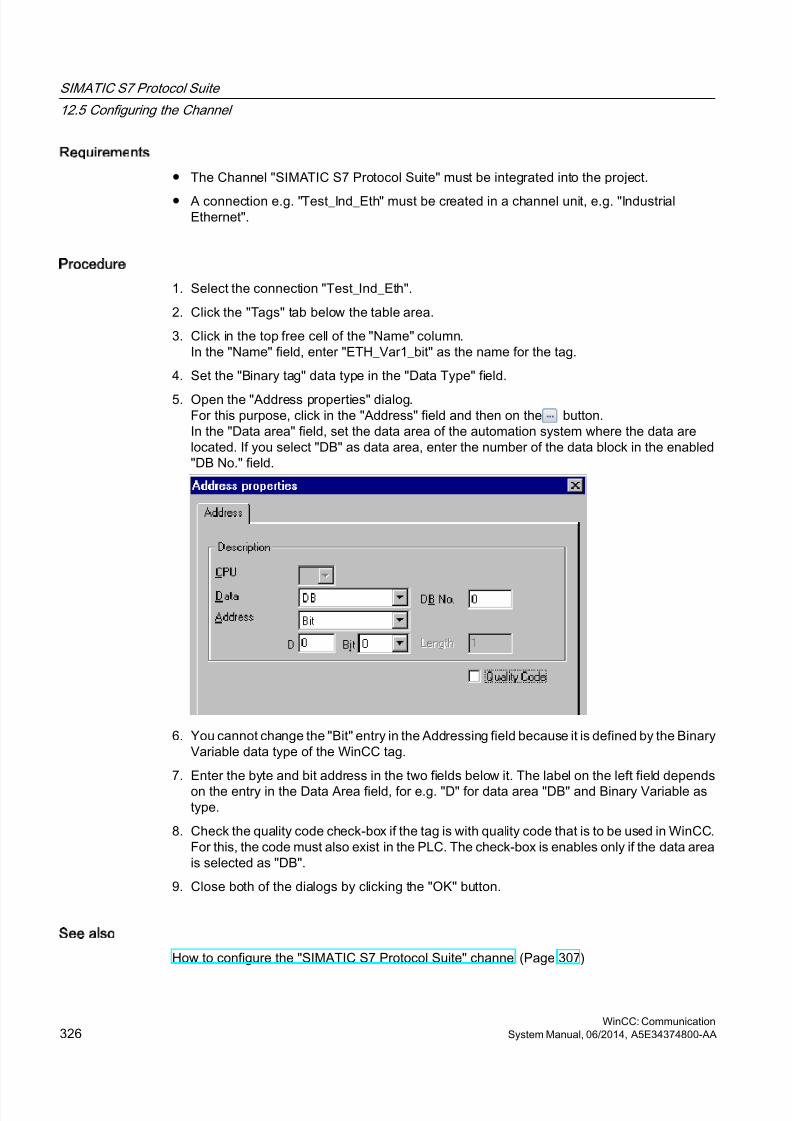
8/20/2019 WinCC Communication en-US en-US
http://slidepdf.com/reader/full/wincc-communication-en-us-en-us 326/527
Requirements
● The Channel "SIMATIC S7 Protocol Suite" must be integrated into the project.
● A connection e.g. "Test_Ind_Eth" must be created in a channel unit, e.g. "IndustrialEthernet".
Procedure
1. Select the connection "Test_Ind_Eth".
2. Click the "Tags" tab below the table area.
3. Click in the top free cell of the "Name" column.In the "Name" field, enter "ETH_Var1_bit" as the name for the tag.
4. Set the "Binary tag" data type in the "Data Type" field.
5. Open the "Address properties" dialog.For this purpose, click in the "Address" field and then on the button.In the "Data area" field, set the data area of the automation system where the data arelocated. If you select "DB" as data area, enter the number of the data block in the enabled"DB No." field.
6. You cannot change the "Bit" entry in the Addressing field because it is defined by the BinaryVariable data type of the WinCC tag.
7. Enter the byte and bit address in the two fields below it. The label on the left field dependson the entry in the Data Area field, for e.g. "D" for data area "DB" and Binary Variable astype.
8. Check the quality code check-box if the tag is with quality code that is to be used in WinCC.For this, the code must also exist in the PLC. The check-box is enables only if the data areais selected as "DB".
9. Close both of the dialogs by clicking the "OK" button.
See also
How to configure the "SIMATIC S7 Protocol Suite" channel (Page 307)
SIMATIC S7 Protocol Suite
12.5 Configuring the Channel
WinCC: Communication326 System Manual, 06/2014, A5E34374800-AA
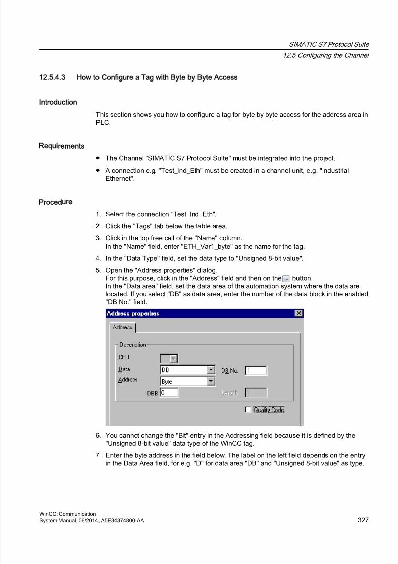
8/20/2019 WinCC Communication en-US en-US
http://slidepdf.com/reader/full/wincc-communication-en-us-en-us 327/527
12.5.4.3 How to Configure a Tag with Byte by Byte Access
Introduction
This section shows you how to configure a tag for byte by byte access for the address area inPLC.
Requirements
● The Channel "SIMATIC S7 Protocol Suite" must be integrated into the project.
● A connection e.g. "Test_Ind_Eth" must be created in a channel unit, e.g. "IndustrialEthernet".
Procedure
1. Select the connection "Test_Ind_Eth".
2. Click the "Tags" tab below the table area.
3. Click in the top free cell of the "Name" column.In the "Name" field, enter "ETH_Var1_byte" as the name for the tag.
4. In the "Data Type" field, set the data type to "Unsigned 8-bit value".
5. Open the "Address properties" dialog.For this purpose, click in the "Address" field and then on the button.In the "Data area" field, set the data area of the automation system where the data are
located. If you select "DB" as data area, enter the number of the data block in the enabled"DB No." field.
6. You cannot change the "Bit" entry in the Addressing field because it is defined by the"Unsigned 8-bit value" data type of the WinCC tag.
7. Enter the byte address in the field below. The label on the left field depends on the entryin the Data Area field, for e.g. "D" for data area "DB" and "Unsigned 8-bit value" as type.
SIMATIC S7 Protocol Suite
12.5 Configuring the Channel
WinCC: CommunicationSystem Manual, 06/2014, A5E34374800-AA 327
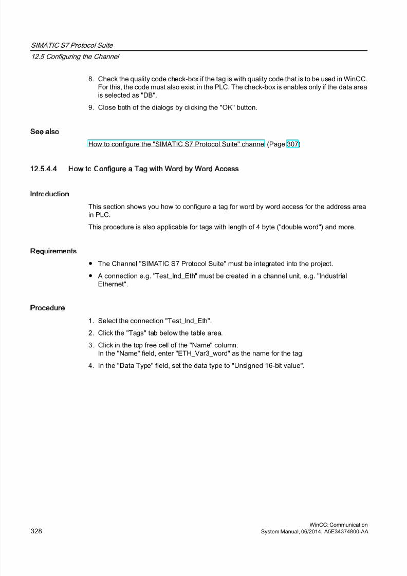
8/20/2019 WinCC Communication en-US en-US
http://slidepdf.com/reader/full/wincc-communication-en-us-en-us 328/527
8. Check the quality code check-box if the tag is with quality code that is to be used in WinCC.For this, the code must also exist in the PLC. The check-box is enables only if the data areais selected as "DB".
9. Close both of the dialogs by clicking the "OK" button.
See also
How to configure the "SIMATIC S7 Protocol Suite" channel (Page 307)
12.5.4.4 How to Configure a Tag with Word by Word Access
Introduction
This section shows you how to configure a tag for word by word access for the address areain PLC.
This procedure is also applicable for tags with length of 4 byte ("double word") and more.
Requirements
● The Channel "SIMATIC S7 Protocol Suite" must be integrated into the project.
● A connection e.g. "Test_Ind_Eth" must be created in a channel unit, e.g. "IndustrialEthernet".
Procedure
1. Select the connection "Test_Ind_Eth".
2. Click the "Tags" tab below the table area.
3. Click in the top free cell of the "Name" column.In the "Name" field, enter "ETH_Var3_word" as the name for the tag.
4. In the "Data Type" field, set the data type to "Unsigned 16-bit value".
SIMATIC S7 Protocol Suite
12.5 Configuring the Channel
WinCC: Communication328 System Manual, 06/2014, A5E34374800-AA
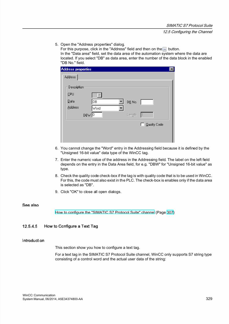
8/20/2019 WinCC Communication en-US en-US
http://slidepdf.com/reader/full/wincc-communication-en-us-en-us 329/527
5. Open the "Address properties" dialog.For this purpose, click in the "Address" field and then on the button.In the "Data area" field, set the data area of the automation system where the data are
located. If you select "DB" as data area, enter the number of the data block in the enabled"DB No." field.
6. You cannot change the "Word" entry in the Addressing field because it is defined by the"Unsigned 16-bit value" data type of the WinCC tag.
7. Enter the numeric value of the address in the Addressing field. The label on the left fielddepends on the entry in the Data Area field, for e.g. "DBW" for "Unsigned 16-bit value" as
type.8. Check the quality code check-box if the tag is with quality code that is to be used in WinCC.
For this, the code must also exist in the PLC. The check-box is enables only if the data areais selected as "DB".
9. Click "OK" to close all open dialogs.
See also
How to configure the "SIMATIC S7 Protocol Suite" channel (Page 307)
12.5.4.5 How to Configure a Text Tag
Introduction
This section show you how to configure a text tag.
For a text tag in the SIMATIC S7 Protocol Suite channel, WinCC only supports S7 string typeconsisting of a control word and the actual user data of the string:
SIMATIC S7 Protocol Suite
12.5 Configuring the Channel
WinCC: CommunicationSystem Manual, 06/2014, A5E34374800-AA 329

8/20/2019 WinCC Communication en-US en-US
http://slidepdf.com/reader/full/wincc-communication-en-us-en-us 330/527
● To configure a text tag in WinCC, enter the address of the control word that exists in thePLC memory before the user data. The first byte of the control word contains the customizedmaximum length of the string, the second byte the actual length.
● To insert the data structure in the PLC memory, you must note that the length of the texttag configured in WinCC is extended by 2 bytes of the control word. If the data structuresof the text tag are inserted in the memory directly one after the other, then the subsequentdata will get overwritten.
● New mapping is required for switching the PCS-7 version from V4.01 to V5.0 SP1 becausein the versions before V5.0 the address of the user data was also mentioned whileconfiguring the text tags; from version V5.0 onwards the address of the control word is tobe given.
● While reading, the control word is read along with the user data and the current length isevaluated in the second byte. Only the user data according to the current length includedin the second control byte is transferred at the text tags of WinCC.
● While writing, the actual length of the string is ascertained ("0" character) and the controlbyte with the current length is sent to the PLC along with the user data.
Requirements
● The Channel "SIMATIC S7 Protocol Suite" must be integrated into the project.
● A connection e.g. "Test_Ind_Eth" must be created in a channel unit, e.g. "IndustrialEthernet".
Procedure
1. Select the connection "Test_Ind_Eth".
2. Click the "Tags" tab below the table area.
3. Click in the top free cell of the "Name" column.In the "Name" field, enter "ETH_Var3_Text" as the name for the tag.
4. In the Data Type field, set "Text tag, 8-bit font" as the data type.
SIMATIC S7 Protocol Suite
12.5 Configuring the Channel
WinCC: Communication330 System Manual, 06/2014, A5E34374800-AA
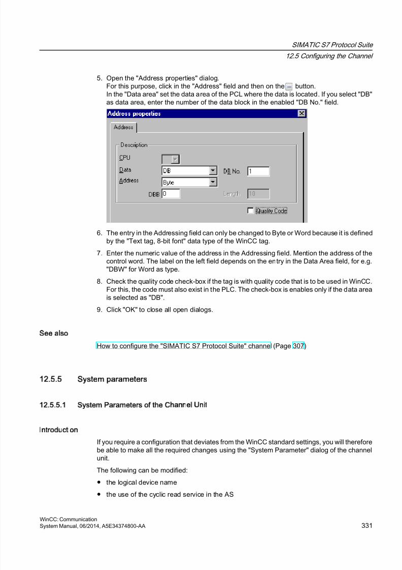
8/20/2019 WinCC Communication en-US en-US
http://slidepdf.com/reader/full/wincc-communication-en-us-en-us 331/527
5. Open the "Address properties" dialog.For this purpose, click in the "Address" field and then on the button.In the "Data area" set the data area of the PCL where the data is located. If you select "DB"
as data area, enter the number of the data block in the enabled "DB No." field.
6. The entry in the Addressing field can only be changed to Byte or Word because it is definedby the "Text tag, 8-bit font" data type of the WinCC tag.
7. Enter the numeric value of the address in the Addressing field. Mention the address of thecontrol word. The label on the left field depends on the entry in the Data Area field, for e.g."DBW" for Word as type.
8. Check the quality code check-box if the tag is with quality code that is to be used in WinCC.For this, the code must also exist in the PLC. The check-box is enables only if the data area
is selected as "DB".9. Click "OK" to close all open dialogs.
See also
How to configure the "SIMATIC S7 Protocol Suite" channel (Page 307)
12.5.5 System parameters
12.5.5.1 System Parameters of the Channel Unit
Introduction
If you require a configuration that deviates from the WinCC standard settings, you will thereforebe able to make all the required changes using the "System Parameter" dialog of the channelunit.
The following can be modified:
● the logical device name
● the use of the cyclic read service in the AS
SIMATIC S7 Protocol Suite
12.5 Configuring the Channel
WinCC: CommunicationSystem Manual, 06/2014, A5E34374800-AA 331
8/20/2019 WinCC Communication en-US en-US
http://slidepdf.com/reader/full/wincc-communication-en-us-en-us 332/527
Logical Device Name
Communication between WinCC and the automation system takes place via logical device
names. These names are assigned during the installation of the communications card and areunit-specific. This field will be filled with a default unit-specific entry, e.g. "MPI" in the case ofchannel unit "MPI".
Using cyclic reading services in the PLC
It is possible to specify whether or not the cyclic read services of S7-PLC (also referred to ascyclic tag services) should be used. These cyclic read services group the tags that are to beread cyclically into individual request and transfer these to the PLC. The PLC will transfer therequired data immediately on receipt of the request and will also transfer the data each timethe cycle time elapses.
When the cyclic read services are activated, modification transfers can also be used. The datawill then only be transferred when the values have changed. The function must be supportedby the PLC.
Note
The system parameters on the SIMATIC S7 and Unit tabs are unit-specific and can thus beset separately for each channel unit of the channel.
See also
How to Change the Logical Device Name (Page 335)
How to Configure the System Parameters (Page 333)
Cyclic read services in PLC (Page 332)
12.5.5.2 Cyclic read services in PLC
Introduction
In the system parameters of the "SIMATIC S7 Protocol Suite" channel, it is also possible tospecify whether or not the cyclic read services of the S7-AS(also referred to as cyclic tag
services) should be used. These cyclic read services group the tags that are to be readcyclically into individual request and transfer these to the PLC. The PLC will transfer therequired data immediately on receipt of the request and will also transfer the data each timethe cycle time elapses. When the requested data is no longer required, e.g. in the case of ascreen change, WinCC will delete the cyclic read service in the PLC.
In normal cases, use should be made of the cyclic read services in the PLC. For this reason,the corresponding check box is already activated (default setting) in the system parametersof the channel unit. This setting should only be changed if you do not wish to use the cyclicservices.
Modification transfers can only be used when the cyclic read services are activated. The datawill then only transferred from the AS when a value has changed and only once per AS cycle.The function must be supported by the PLC.
SIMATIC S7 Protocol Suite
12.5 Configuring the Channel
WinCC: Communication332 System Manual, 06/2014, A5E34374800-AA
8/20/2019 WinCC Communication en-US en-US
http://slidepdf.com/reader/full/wincc-communication-en-us-en-us 333/527
The use of the cyclic read services and modification transfers relieves both the AS and AS-OScommunication, since read requests need not be continually sent to the AS and processedthere.
In the case of acyclic read services, the tags that are to be read are combined in an individualrequest and transferred to the PLC. The PLC only sends the required data once. The formationof the cycle for the request is carried out by WinCC.
The number of cyclic read services in a CPU
The number of cyclic read services will depend on the resources that are available in the S7-PLC. A maximum of four cyclic services are available for an S7-300 max. and a maximum of32 for an S7-416 or 417. This number applies for all participants communicating with the PLC,i.e. if several WinCC systems are communicating with an S7-PLC, they will have to share theresources that are available. If the maximum number of resources is exceeded, access to afurther cyclic read service will be refused. WinCC will then have to request this data using
acyclic read requests and will also have to execute cycle formation.
Requesting external tags in scripts
The utilization of the cyclic read service has no influence on the initial update once a picturehas been opened if the picture that has been selected does not contain any scripts that requestexternal tags using the function "GetTagWord()". If scripts are executed with "GetTagWord()"when a picture is opened, the incorrect configuration of this script could result in new tagrequests being sent to this channel repeatedly following a picture change. If external tags arerequired in a script, "Tag" should be entered as a trigger event.
12.5.5.3 How to Configure the System Parameters
Introduction
In this section, we will show you how to configure the system parameters of the Channel"SIMATIC S7 Protocol Suite".
The "System Parameters" dialog comprises two tabs:
● SIMATIC S7 tab
● Unit tab
The system parameters on the SIMATIC S7 and Unit tabs are unit-specific and can thus beset separately for each channel unit of the channel.
These tabs are identical for all channel units of the S7 channel. Consequently, the dialog forthe channel unit "MPI" is used in all examples.
Any changes that are made to the parameter values will only take effect after WinCC has beenrestarted.
Note
When copying the project to another computer, the settings on the Unit tab will be retained,the settings on the SIMATIC S7 tab, however, will not.
SIMATIC S7 Protocol Suite
12.5 Configuring the Channel
WinCC: CommunicationSystem Manual, 06/2014, A5E34374800-AA 333
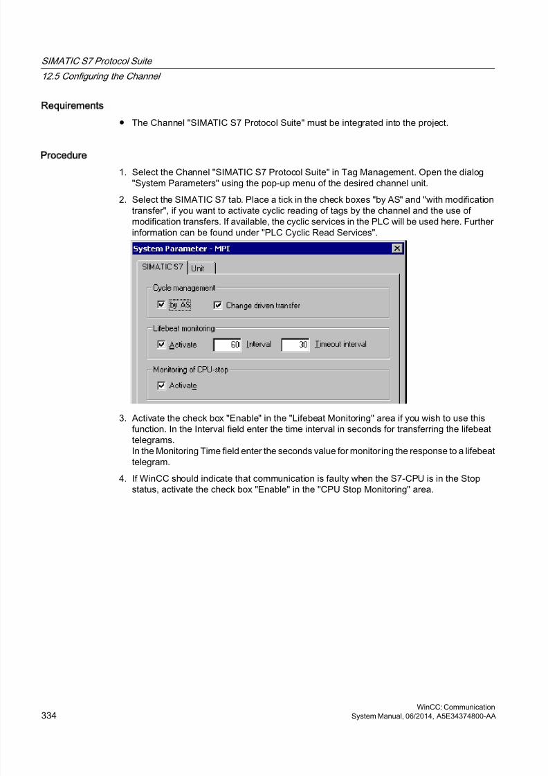
8/20/2019 WinCC Communication en-US en-US
http://slidepdf.com/reader/full/wincc-communication-en-us-en-us 334/527
Requirements
● The Channel "SIMATIC S7 Protocol Suite" must be integrated into the project.
Procedure
1. Select the Channel "SIMATIC S7 Protocol Suite" in Tag Management. Open the dialog"System Parameters" using the pop-up menu of the desired channel unit.
2. Select the SIMATIC S7 tab. Place a tick in the check boxes "by AS" and "with modificationtransfer", if you want to activate cyclic reading of tags by the channel and the use ofmodification transfers. If available, the cyclic services in the PLC will be used here. Furtherinformation can be found under "PLC Cyclic Read Services".
3. Activate the check box "Enable" in the "Lifebeat Monitoring" area if you wish to use thisfunction. In the Interval field enter the time interval in seconds for transferring the lifebeattelegrams.In the Monitoring Time field enter the seconds value for monitoring the response to a lifebeattelegram.
4. If WinCC should indicate that communication is faulty when the S7-CPU is in the Stopstatus, activate the check box "Enable" in the "CPU Stop Monitoring" area.
SIMATIC S7 Protocol Suite
12.5 Configuring the Channel
WinCC: Communication334 System Manual, 06/2014, A5E34374800-AA
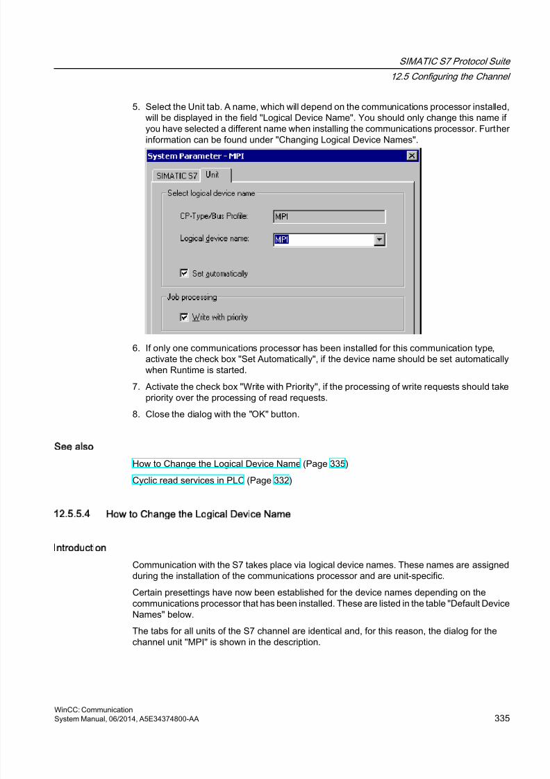
8/20/2019 WinCC Communication en-US en-US
http://slidepdf.com/reader/full/wincc-communication-en-us-en-us 335/527
5. Select the Unit tab. A name, which will depend on the communications processor installed,will be displayed in the field "Logical Device Name". You should only change this name ifyou have selected a different name when installing the communications processor. Further
information can be found under "Changing Logical Device Names".
6. If only one communications processor has been installed for this communication type,activate the check box "Set Automatically", if the device name should be set automaticallywhen Runtime is started.
7. Activate the check box "Write with Priority", if the processing of write requests should takepriority over the processing of read requests.
8. Close the dialog with the "OK" button.
See also
How to Change the Logical Device Name (Page 335)
Cyclic read services in PLC (Page 332)
12.5.5.4 How to Change the Logical Device Name
Introduction
Communication with the S7 takes place via logical device names. These names are assignedduring the installation of the communications processor and are unit-specific.
Certain presettings have now been established for the device names depending on thecommunications processor that has been installed. These are listed in the table "Default DeviceNames" below.
The tabs for all units of the S7 channel are identical and, for this reason, the dialog for thechannel unit "MPI" is shown in the description.
SIMATIC S7 Protocol Suite
12.5 Configuring the Channel
WinCC: CommunicationSystem Manual, 06/2014, A5E34374800-AA 335
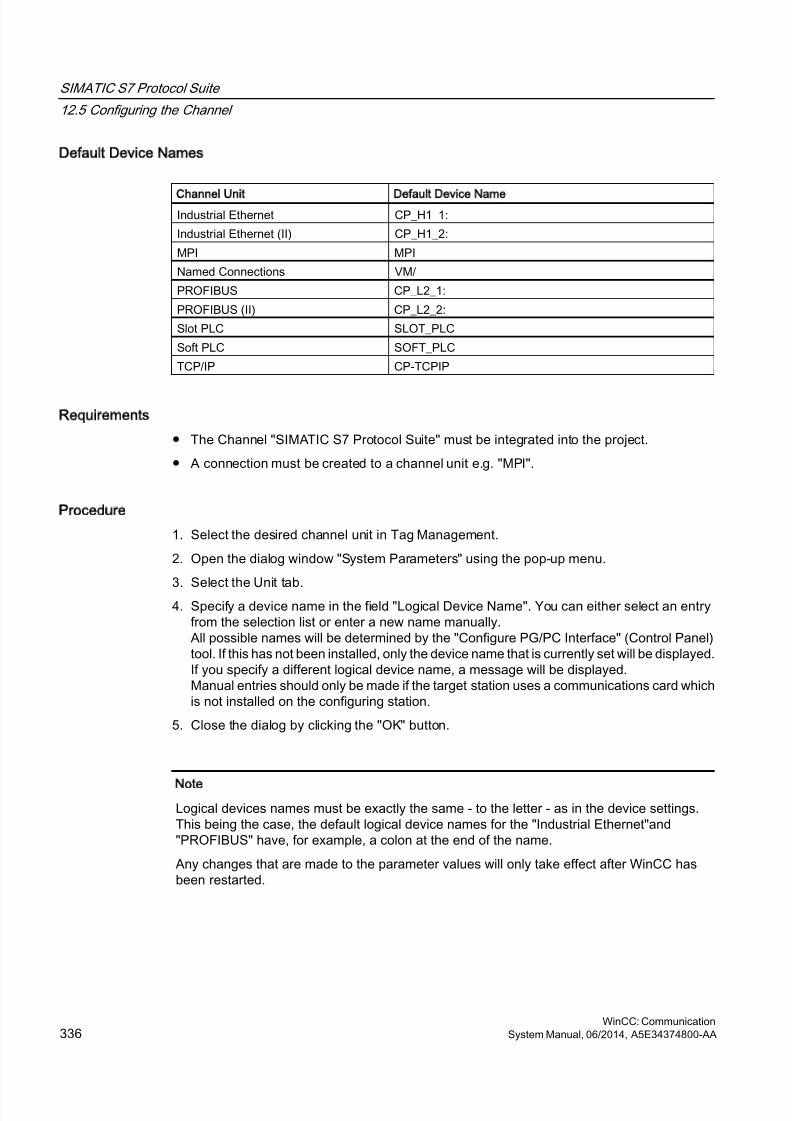
8/20/2019 WinCC Communication en-US en-US
http://slidepdf.com/reader/full/wincc-communication-en-us-en-us 336/527
Default Device Names
Channel Unit Default Device Name
Industrial Ethernet CP_H1_1:
Industrial Ethernet (II) CP_H1_2:
MPI MPI
Named Connections VM/
PROFIBUS CP_L2_1:
PROFIBUS (II) CP_L2_2:
Slot PLC SLOT_PLC
Soft PLC SOFT_PLC
TCP/IP CP-TCPIP
Requirements
● The Channel "SIMATIC S7 Protocol Suite" must be integrated into the project.
● A connection must be created to a channel unit e.g. "MPI".
Procedure
1. Select the desired channel unit in Tag Management.
2. Open the dialog window "System Parameters" using the pop-up menu.
3. Select the Unit tab.4. Specify a device name in the field "Logical Device Name". You can either select an entry
from the selection list or enter a new name manually.All possible names will be determined by the "Configure PG/PC Interface" (Control Panel)tool. If this has not been installed, only the device name that is currently set will be displayed.If you specify a different logical device name, a message will be displayed.Manual entries should only be made if the target station uses a communications card whichis not installed on the configuring station.
5. Close the dialog by clicking the "OK" button.
Note
Logical devices names must be exactly the same - to the letter - as in the device settings.This being the case, the default logical device names for the "Industrial Ethernet"and"PROFIBUS" have, for example, a colon at the end of the name.
Any changes that are made to the parameter values will only take effect after WinCC hasbeen restarted.
SIMATIC S7 Protocol Suite
12.5 Configuring the Channel
WinCC: Communication336 System Manual, 06/2014, A5E34374800-AA
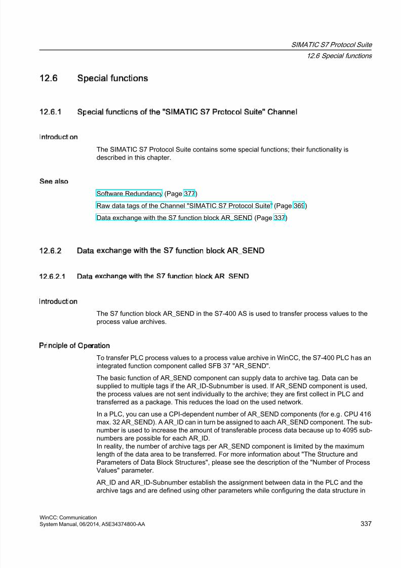
8/20/2019 WinCC Communication en-US en-US
http://slidepdf.com/reader/full/wincc-communication-en-us-en-us 337/527
12.6 Special functions
12.6.1 Special functions of the SIMATIC S7 Protocol Suite Channel
Introduction
The SIMATIC S7 Protocol Suite contains some special functions; their functionality isdescribed in this chapter.
See also
Software Redundancy (Page 377)
Raw data tags of the Channel "SIMATIC S7 Protocol Suite" (Page 369)
Data exchange with the S7 function block AR_SEND (Page 337)
12.6.2 Data exchange with the S7 function block AR_SEND
12.6.2.1 Data exchange with the S7 function block AR_SEND
Introduction
The S7 function block AR_SEND in the S7-400 AS is used to transfer process values to theprocess value archives.
Principle of Operation
To transfer PLC process values to a process value archive in WinCC, the S7-400 PLC has anintegrated function component called SFB 37 "AR_SEND".
The basic function of AR_SEND component can supply data to archive tag. Data can besupplied to multiple tags if the AR_ID-Subnumber is used. If AR_SEND component is used,the process values are not sent individually to the archive; they are first collect in PLC andtransferred as a package. This reduces the load on the used network.
In a PLC, you can use a CPI-dependent number of AR_SEND components (for e.g. CPU 416max. 32 AR_SEND). A AR_ID can in turn be assigned to aach AR_SEND component. The sub-number is used to increase the amount of transferable process data because up to 4095 sub-numbers are possible for each AR_ID.In reality, the number of archive tags per AR_SEND component is limited by the maximumlength of the data area to be transferred. For more information about "The Structure andParameters of Data Block Structures", please see the description of the "Number of ProcessValues" parameter.
AR_ID and AR_ID-Subnumber establish the assignment between data in the PLC and thearchive tags and are defined using other parameters while configuring the data structure in
SIMATIC S7 Protocol Suite
12.6 Special functions
WinCC: CommunicationSystem Manual, 06/2014, A5E34374800-AA 337
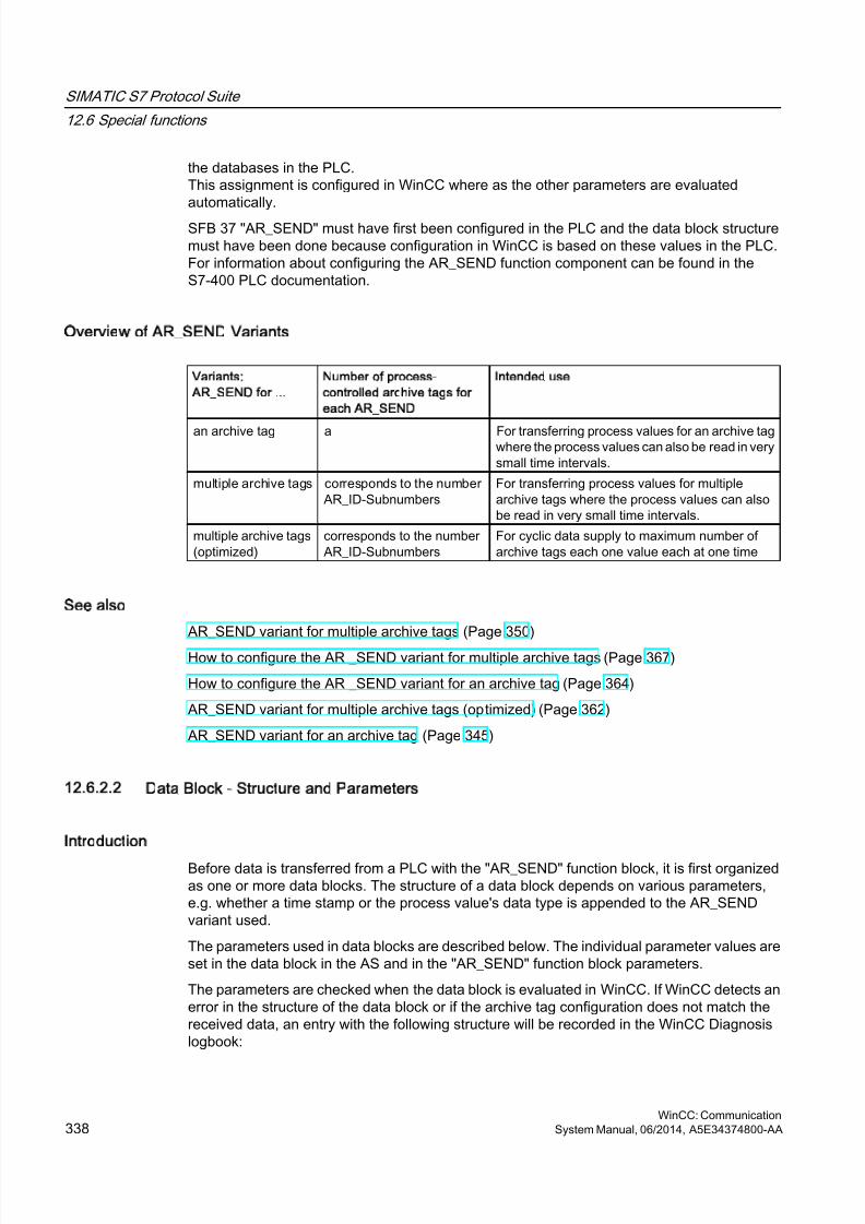
8/20/2019 WinCC Communication en-US en-US
http://slidepdf.com/reader/full/wincc-communication-en-us-en-us 338/527
the databases in the PLC.This assignment is configured in WinCC where as the other parameters are evaluatedautomatically.
SFB 37 "AR_SEND" must have first been configured in the PLC and the data block structuremust have been done because configuration in WinCC is based on these values in the PLC.For information about configuring the AR_SEND function component can be found in theS7-400 PLC documentation.
Overview of AR_SEND Variants
Variants:
AR_SEND for ...
Number of process-
controlled archive tags for
each AR_SEND
Intended use
an archive tag a For transferring process values for an archive tagwhere the process values can also be read in verysmall time intervals.
multiple archive tags corresponds to the numberAR_ID-Subnumbers
For transferring process values for multiplearchive tags where the process values can alsobe read in very small time intervals.
multiple archive tags(optimized)
corresponds to the numberAR_ID-Subnumbers
For cyclic data supply to maximum number ofarchive tags each one value each at one time
See also
AR_SEND variant for multiple archive tags (Page 350)
How to configure the AR _SEND variant for multiple archive tags (Page 367)
How to configure the AR _SEND variant for an archive tag (Page 364)
AR_SEND variant for multiple archive tags (optimized) (Page 362)
AR_SEND variant for an archive tag (Page 345)
12.6.2.2 Data Block - Structure and Parameters
Introduction
Before data is transferred from a PLC with the "AR_SEND" function block, it is first organizedas one or more data blocks. The structure of a data block depends on various parameters,e.g. whether a time stamp or the process value's data type is appended to the AR_SENDvariant used.
The parameters used in data blocks are described below. The individual parameter values areset in the data block in the AS and in the "AR_SEND" function block parameters.
The parameters are checked when the data block is evaluated in WinCC. If WinCC detects anerror in the structure of the data block or if the archive tag configuration does not match thereceived data, an entry with the following structure will be recorded in the WinCC Diagnosislogbook:
SIMATIC S7 Protocol Suite
12.6 Special functions
WinCC: Communication338 System Manual, 06/2014, A5E34374800-AA
8/20/2019 WinCC Communication en-US en-US
http://slidepdf.com/reader/full/wincc-communication-en-us-en-us 339/527
"Date, Time, 1003080 ,4 ,user name, computer name, NRMS7PMC, PdeReceive: Unknownparameter AR_SEND from connection connectionname ...+ additional information for errordescription"
If the message system has been configured with the WinCC System Messages, this diagnosisentry will also trigger the OS process control message numbered 1003080. The text of thelogbook entry will be found in this message's comment.
Structure of a Data Block
Each data block consists of a header and a user data area:
● The header contains information about the process values and their cycle, and possibly atime stamp.
● The user data area contains the actual process values.
One or more data blocks form the data area to be transferred.
Note
In the data blocks, each line represents two bytes. Process values can be one or more byteslong, depending on their data type. Further information can be found in the description of the"Number of Process Values" parameter.
Description of parameters
Header Type
The Header Type defines the type of information that is contained in the header.
SIMATIC S7 Protocol Suite
12.6 Special functions
WinCC: CommunicationSystem Manual, 06/2014, A5E34374800-AA 339
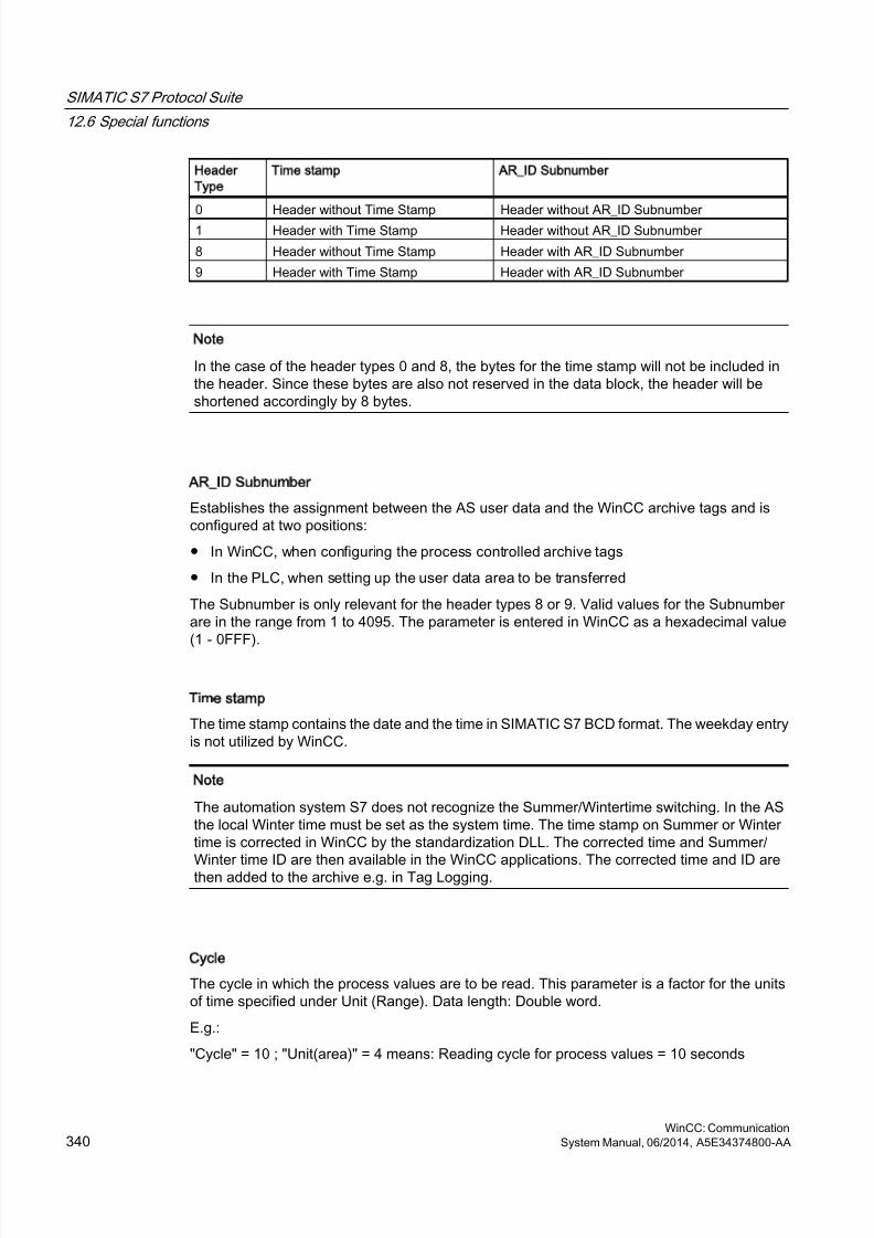
8/20/2019 WinCC Communication en-US en-US
http://slidepdf.com/reader/full/wincc-communication-en-us-en-us 340/527
Header
Type
Time stamp AR_ID Subnumber
0 Header without Time Stamp Header without AR_ID Subnumber 1 Header with Time Stamp Header without AR_ID Subnumber
8 Header without Time Stamp Header with AR_ID Subnumber
9 Header with Time Stamp Header with AR_ID Subnumber
Note
In the case of the header types 0 and 8, the bytes for the time stamp will not be included inthe header. Since these bytes are also not reserved in the data block, the header will beshortened accordingly by 8 bytes.
AR_ID Subnumber
Establishes the assignment between the AS user data and the WinCC archive tags and isconfigured at two positions:
● In WinCC, when configuring the process controlled archive tags
● In the PLC, when setting up the user data area to be transferred
The Subnumber is only relevant for the header types 8 or 9. Valid values for the Subnumberare in the range from 1 to 4095. The parameter is entered in WinCC as a hexadecimal value(1 - 0FFF).
Time stamp
The time stamp contains the date and the time in SIMATIC S7 BCD format. The weekday entryis not utilized by WinCC.
Note
The automation system S7 does not recognize the Summer/Wintertime switching. In the ASthe local Winter time must be set as the system time. The time stamp on Summer or Wintertime is corrected in WinCC by the standardization DLL. The corrected time and Summer/Winter time ID are then available in the WinCC applications. The corrected time and ID arethen added to the archive e.g. in Tag Logging.
Cycle
The cycle in which the process values are to be read. This parameter is a factor for the unitsof time specified under Unit (Range). Data length: Double word.
E.g.:
"Cycle" = 10 ; "Unit(area)" = 4 means: Reading cycle for process values = 10 seconds
SIMATIC S7 Protocol Suite
12.6 Special functions
WinCC: Communication340 System Manual, 06/2014, A5E34374800-AA
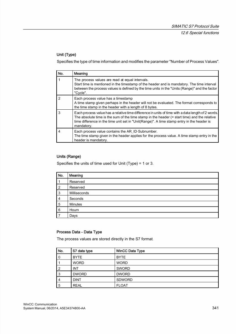
8/20/2019 WinCC Communication en-US en-US
http://slidepdf.com/reader/full/wincc-communication-en-us-en-us 341/527
Unit (Type)
Specifies the type of time information and modifies the parameter "Number of Process Values".
No. Meaning
1 The process values are read at equal intervals.Start time is mentioned in the timestamp of the header and is mandatory. The time intervalbetween the process values is defined by the time units in the "Units (Range)" and the factor"Cycle".
2 Each process value has a timestampA time stamp given perhaps in the header will not be evaluated. The format corresponds tothe time stamp in the header with a length of 8 bytes.
3 Each process value has a relative time difference in units of time with a data length of 2 words.
The absolute time is the sum of the time stamp in the header (= start time) and the relativetime difference in the time unit set in "Unit(Range)". A time stamp entry in the header ismandatory.
4 Each process value contains the AR_ID-Subnumber.The time stamp given in the header applies for the process value. A time stamp entry in theheader is mandatory.
Units (Range)
Specifies the units of time used for Unit (Type) = 1 or 3.
No. Meaning
1 Reserved
2 Reserved
3 Milliseconds
4 Seconds
5 Minutes
6 Hours
7 Days
Process Data - Data Type
The process values are stored directly in the S7 format.
No. S7 data type WinCC Data Type
0 BYTE BYTE
1 WORD WORD
2 INT SWORD
3 DWORD DWORD
4 DINT SDWORD
5 REAL FLOAT
SIMATIC S7 Protocol Suite
12.6 Special functions
WinCC: CommunicationSystem Manual, 06/2014, A5E34374800-AA 341
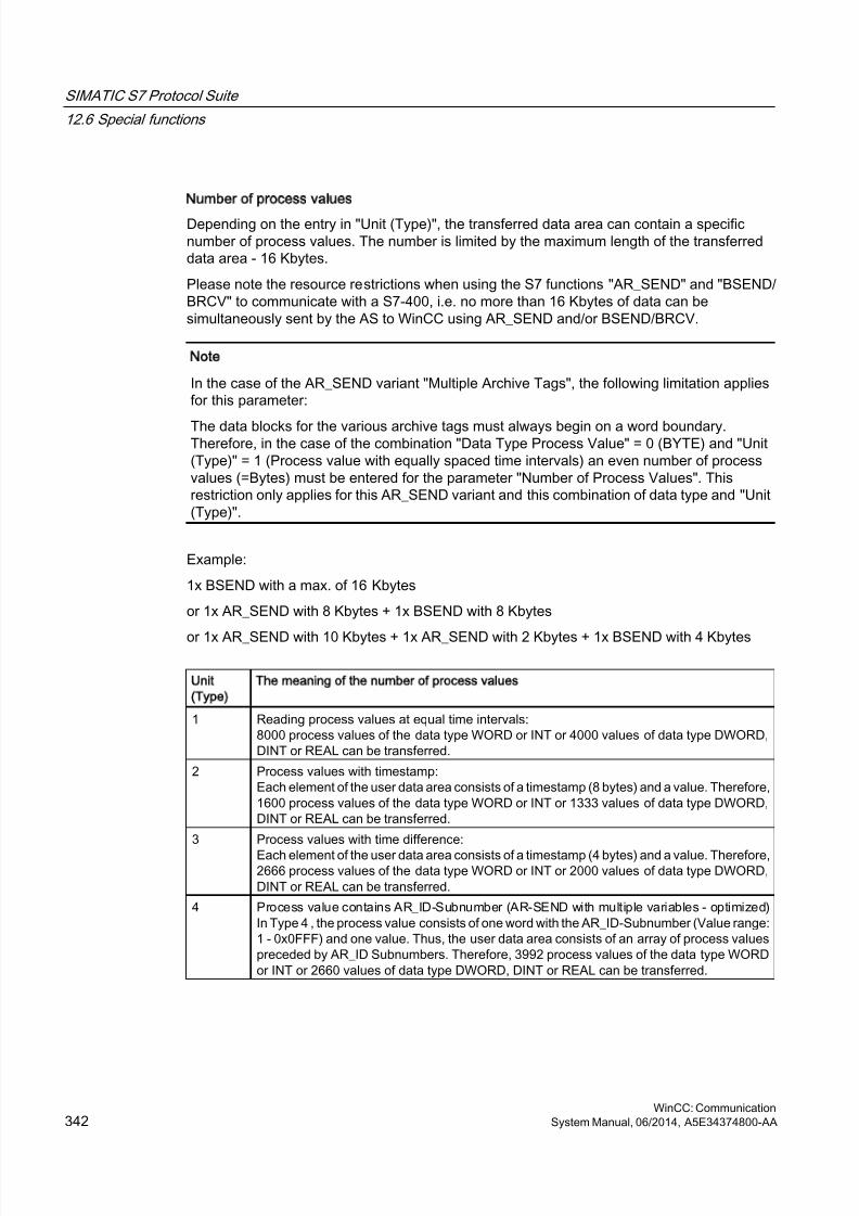
8/20/2019 WinCC Communication en-US en-US
http://slidepdf.com/reader/full/wincc-communication-en-us-en-us 342/527
Number of process values
Depending on the entry in "Unit (Type)", the transferred data area can contain a specificnumber of process values. The number is limited by the maximum length of the transferreddata area - 16 Kbytes.
Please note the resource restrictions when using the S7 functions "AR_SEND" and "BSEND/BRCV" to communicate with a S7-400, i.e. no more than 16 Kbytes of data can besimultaneously sent by the AS to WinCC using AR_SEND and/or BSEND/BRCV.
Note
In the case of the AR_SEND variant "Multiple Archive Tags", the following limitation appliesfor this parameter:
The data blocks for the various archive tags must always begin on a word boundary.Therefore, in the case of the combination "Data Type Process Value" = 0 (BYTE) and "Unit(Type)" = 1 (Process value with equally spaced time intervals) an even number of processvalues (=Bytes) must be entered for the parameter "Number of Process Values". Thisrestriction only applies for this AR_SEND variant and this combination of data type and "Unit(Type)".
Example:
1x BSEND with a max. of 16 Kbytes
or 1x AR_SEND with 8 Kbytes + 1x BSEND with 8 Kbytes
or 1x AR_SEND with 10 Kbytes + 1x AR_SEND with 2 Kbytes + 1x BSEND with 4 Kbytes
Unit
(Type)
The meaning of the number of process values
1 Reading process values at equal time intervals:8000 process values of the data type WORD or INT or 4000 values of data type DWORD,DINT or REAL can be transferred.
2 Process values with timestamp:Each element of the user data area consists of a timestamp (8 bytes) and a value. Therefore,1600 process values of the data type WORD or INT or 1333 values of data type DWORD,DINT or REAL can be transferred.
3 Process values with time difference:
Each element of the user data area consists of a timestamp (4 bytes) and a value. Therefore,2666 process values of the data type WORD or INT or 2000 values of data type DWORD,DINT or REAL can be transferred.
4 Process value contains AR_ID-Subnumber (AR-SEND with multiple variables - optimized)In Type 4 , the process value consists of one word with the AR_ID-Subnumber (Value range:1 - 0x0FFF) and one value. Thus, the user data area consists of an array of process valuespreceded by AR_ID Subnumbers. Therefore, 3992 process values of the data type WORDor INT or 2660 values of data type DWORD, DINT or REAL can be transferred.
SIMATIC S7 Protocol Suite
12.6 Special functions
WinCC: Communication342 System Manual, 06/2014, A5E34374800-AA
8/20/2019 WinCC Communication en-US en-US
http://slidepdf.com/reader/full/wincc-communication-en-us-en-us 343/527
Note
The AR_ID Subnumbers given in the data blocks must all be configured in WinCC. WinCCwill stop interpreting the user data, if a not-configured subnumber is found.
The data blocks for the various archive tags must always begin on a word boundary.Therefore, with the data type BYTE and "Unit (Type)" = 1 (Process value with equally spacedtime intervals), an even number of process values (=Bytes) must be entered for the parameter"Number of Process Values". This restriction only applies for this AR_SEND variant and thiscombination of data type and "Unit (Type)".
See also
How to configure the AR _SEND variant for multiple archive tags (Page 367)
How to configure the AR _SEND variant for an archive tag (Page 364)
AR_SEND variant for multiple archive tags (optimized) (Page 362)
AR_SEND variant for multiple archive tags (Page 350)
AR_SEND variant for an archive tag (Page 345)
12.6.2.3 Overview of the properties of the AR_SEND variants
Introduction
On the basis of examples, the tables show the properties and possible parameter values fordifferent AR_SEND variants.
The tables do not display all of the possible combinations.
The columns "Header Type" to "Process Value Data Type" are presented in the order that theyappear in the header.
Note
The values for AR_ID and AR_ID Subnumber are set together with those of the otherparameters while configuring the function block "AR_SEND" and the data structure in thedata block in the AS.
SIMATIC S7 Protocol Suite
12.6 Special functions
WinCC: CommunicationSystem Manual, 06/2014, A5E34374800-AA 343
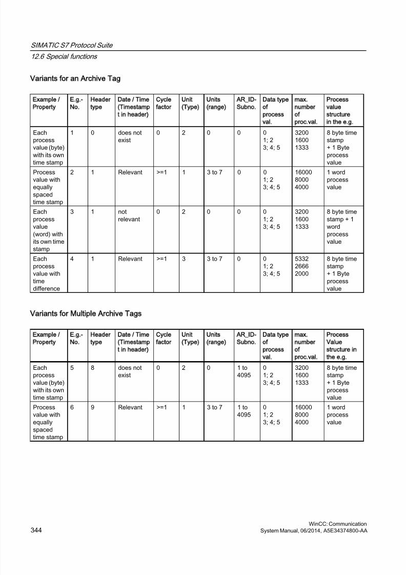
8/20/2019 WinCC Communication en-US en-US
http://slidepdf.com/reader/full/wincc-communication-en-us-en-us 344/527
Variants for an Archive Tag
Example /
Property
E.g.-
No.
Header
type
Date / Time
(Timestamp
t in header)
Cycle
factor
Unit
(Type)
Units
(range)
AR_ID-
Subno.
Data type
of
process
val.
max.
number
of
proc.val.
Process
value
structure
in the e.g.
Eachprocessvalue (byte)with its owntime stamp
1 0 does notexist
0 2 0 0 01; 23; 4; 5
320016001333
8 byte timestamp+ 1 Byteprocessvalue
Processvalue withequallyspaced
time stamp
2 1 Relevant >=1 1 3 to 7 0 01; 23; 4; 5
1600080004000
1 wordprocessvalue
Eachprocessvalue(word) withits own timestamp
3 1 notrelevant
0 2 0 0 01; 23; 4; 5
320016001333
8 byte timestamp + 1wordprocessvalue
Eachprocessvalue withtimedifference
4 1 Relevant >=1 3 3 to 7
0 01; 23; 4; 5
533226662000
8 byte timestamp+ 1 Byteprocessvalue
Variants for Multiple Archive Tags
Example /
Property
E.g.-
No.
Header
type
Date / Time
(Timestamp
t in header)
Cycle
factor
Unit
(Type)
Units
(range)
AR_ID-
Subno.
Data type
of
process
val.
max.
number
of
proc.val.
Process
Value
structure in
the e.g.
Eachprocessvalue (byte)with its owntime stamp
5 8 does notexist
0 2 0 1 to4095
01; 23; 4; 5
320016001333
8 byte timestamp+ 1 Byteprocessvalue
Processvalue withequallyspacedtime stamp
6 9 Relevant >=1 1 3 to 7 1 to4095
01; 23; 4; 5
1600080004000
1 wordprocessvalue
SIMATIC S7 Protocol Suite
12.6 Special functions
WinCC: Communication344 System Manual, 06/2014, A5E34374800-AA
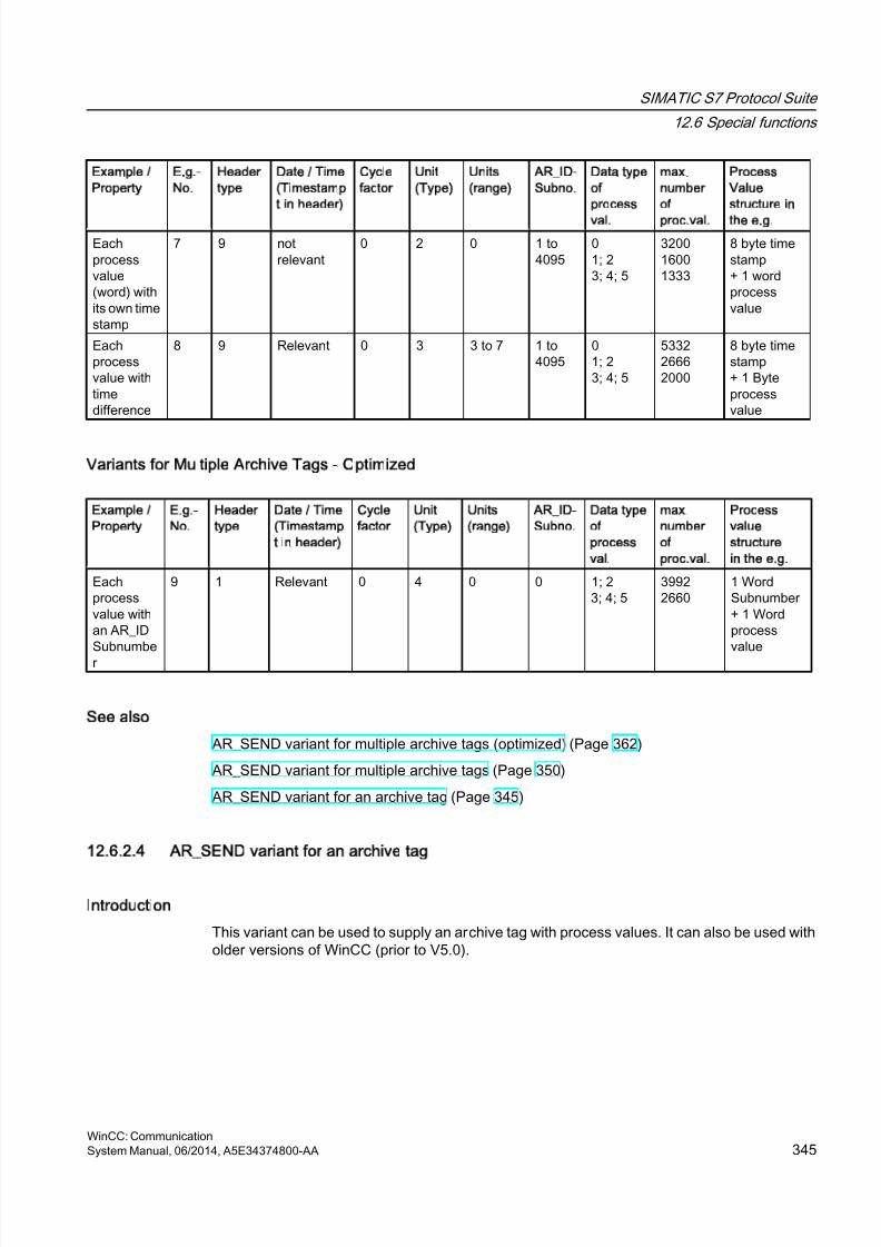
8/20/2019 WinCC Communication en-US en-US
http://slidepdf.com/reader/full/wincc-communication-en-us-en-us 345/527
Example /
Property
E.g.-
No.
Header
type
Date / Time
(Timestamp
t in header)
Cycle
factor
Unit
(Type)
Units
(range)
AR_ID-
Subno.
Data type
of
process
val.
max.
number
of
proc.val.
Process
Value
structure in
the e.g.
Eachprocessvalue(word) withits own timestamp
7 9 notrelevant
0 2 0 1 to4095
01; 23; 4; 5
320016001333
8 byte timestamp+ 1 wordprocessvalue
Eachprocessvalue withtimedifference
8 9 Relevant 0 3 3 to 7
1 to4095
01; 23; 4; 5
533226662000
8 byte timestamp+ 1 Byteprocessvalue
Variants for Multiple Archive Tags - Optimized
Example /
Property
E.g.-
No.
Header
type
Date / Time
(Timestamp
t in header)
Cycle
factor
Unit
(Type)
Units
(range)
AR_ID-
Subno.
Data type
of
process
val.
max.
number
of
proc.val.
Process
value
structure
in the e.g.
Eachprocessvalue withan AR_IDSubnumber
9 1 Relevant 0 4 0 0 1; 23; 4; 5
39922660
1 WordSubnumber + 1 Wordprocessvalue
See also
AR_SEND variant for multiple archive tags (optimized) (Page 362)
AR_SEND variant for multiple archive tags (Page 350)
AR_SEND variant for an archive tag (Page 345)
12.6.2.4 AR_SEND variant for an archive tag
Introduction
This variant can be used to supply an archive tag with process values. It can also be used witholder versions of WinCC (prior to V5.0).
SIMATIC S7 Protocol Suite
12.6 Special functions
WinCC: CommunicationSystem Manual, 06/2014, A5E34374800-AA 345
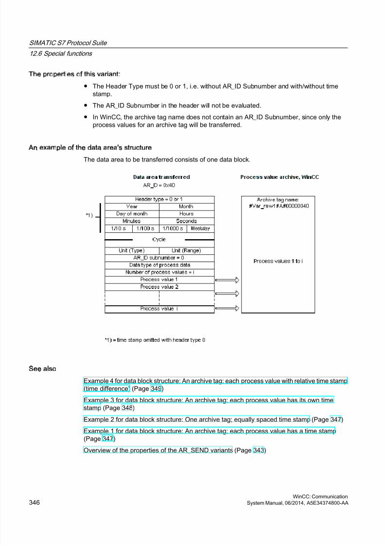
8/20/2019 WinCC Communication en-US en-US
http://slidepdf.com/reader/full/wincc-communication-en-us-en-us 346/527
The properties of this variant:
● The Header Type must be 0 or 1, i.e. without AR_ID Subnumber and with/without time
stamp.● The AR_ID Subnumber in the header will not be evaluated.
● In WinCC, the archive tag name does not contain an AR_ID Subnumber, since only theprocess values for an archive tag will be transferred.
An example of the data area's structure
The data area to be transferred consists of one data block.
See also
Example 4 for data block structure: An archive tag; each process value with relative time stamp(time difference) (Page 349)
Example 3 for data block structure: An archive tag; each process value has its own timestamp (Page 348)
Example 2 for data block structure: One archive tag; equally spaced time stamp (Page 347)
Example 1 for data block structure: An archive tag; each process value has a time stamp (Page 347)
Overview of the properties of the AR_SEND variants (Page 343)
SIMATIC S7 Protocol Suite
12.6 Special functions
WinCC: Communication346 System Manual, 06/2014, A5E34374800-AA
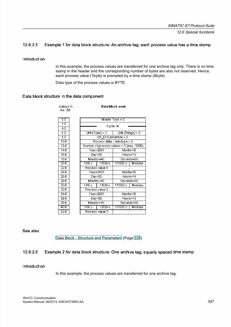
8/20/2019 WinCC Communication en-US en-US
http://slidepdf.com/reader/full/wincc-communication-en-us-en-us 347/527
12.6.2.5 Example 1 for data block structure: An archive tag; each process value has a time stamp
Introduction
In this example, the process values are transferred for one archive tag only. There is no timestamp in the header and the corresponding number of bytes are also not reserved. Hence,each process value (1byte) is preceded by a time stamp (8byte).
Data type of the process values is BYTE.
Data block structure in the data component
See also
Data Block - Structure and Parameters (Page 338)
12.6.2.6 Example 2 for data block structure: One archive tag; equally spaced time stamp
Introduction
In this example, the process values are transferred for one archive tag.
SIMATIC S7 Protocol Suite
12.6 Special functions
WinCC: CommunicationSystem Manual, 06/2014, A5E34374800-AA 347

8/20/2019 WinCC Communication en-US en-US
http://slidepdf.com/reader/full/wincc-communication-en-us-en-us 348/527
The equally spaced time stamp of one second is formed using the parameters "Cycle" = 1 and"Unit (Range)" = 4 (= seconds).
Data type of the process values is WORD.
Data block structure in the data component
See also
Data Block - Structure and Parameters (Page 338)
12.6.2.7 Example 3 for data block structure: An archive tag; each process value has its own time
stamp
Introduction
In this example, the process values are transferred for one archive tag only. The time stampin the header is not important. Hence, each process value (1Word) is preceded by a time stamp(8byte).
Data type of the process values is SWORD.
SIMATIC S7 Protocol Suite
12.6 Special functions
WinCC: Communication348 System Manual, 06/2014, A5E34374800-AA
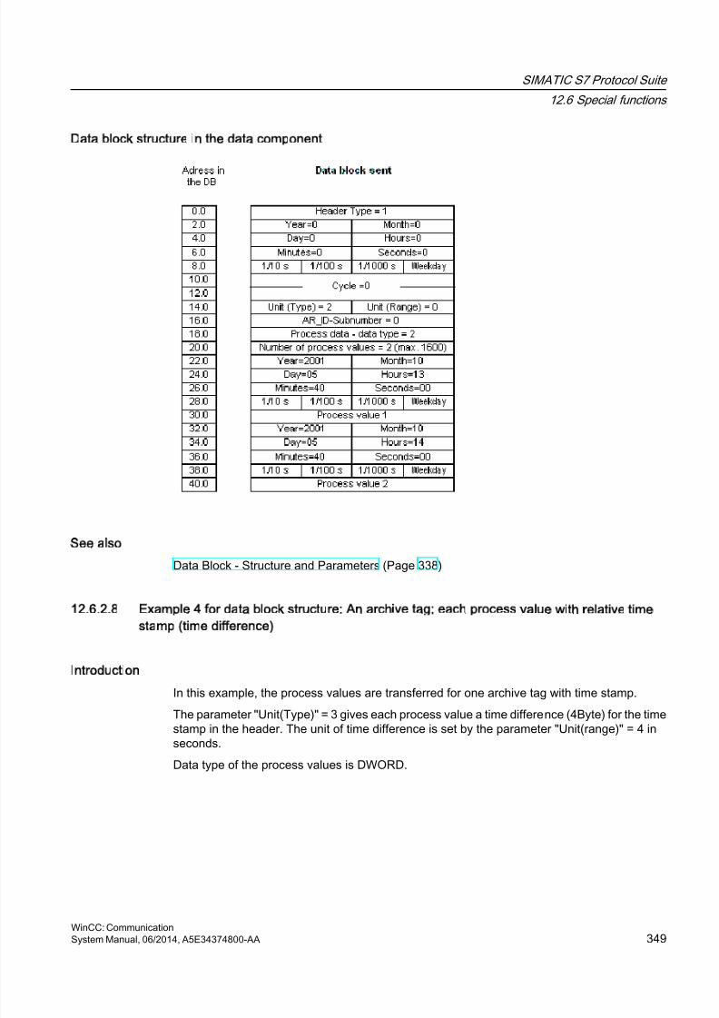
8/20/2019 WinCC Communication en-US en-US
http://slidepdf.com/reader/full/wincc-communication-en-us-en-us 349/527
Data block structure in the data component
See also
Data Block - Structure and Parameters (Page 338)
12.6.2.8 Example 4 for data block structure: An archive tag; each process value with relative time
stamp (time difference)
Introduction
In this example, the process values are transferred for one archive tag with time stamp.
The parameter "Unit(Type)" = 3 gives each process value a time difference (4Byte) for the timestamp in the header. The unit of time difference is set by the parameter "Unit(range)" = 4 inseconds.
Data type of the process values is DWORD.
SIMATIC S7 Protocol Suite
12.6 Special functions
WinCC: CommunicationSystem Manual, 06/2014, A5E34374800-AA 349
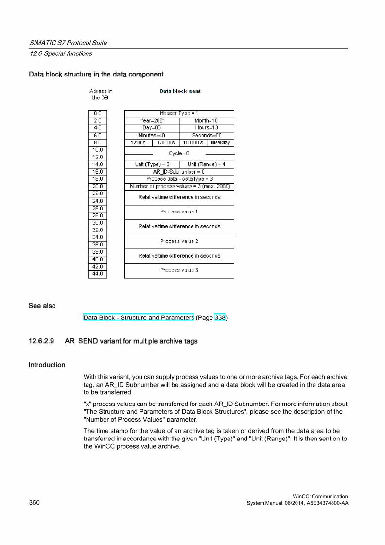
8/20/2019 WinCC Communication en-US en-US
http://slidepdf.com/reader/full/wincc-communication-en-us-en-us 350/527
Data block structure in the data component
See also
Data Block - Structure and Parameters (Page 338)
12.6.2.9 AR_SEND variant for multiple archive tags
Introduction
With this variant, you can supply process values to one or more archive tags. For each archivetag, an AR_ID Subnumber will be assigned and a data block will be created in the data areato be transferred.
"x" process values can be transferred for each AR_ID Subnumber. For more information about"The Structure and Parameters of Data Block Structures", please see the description of the"Number of Process Values" parameter.
The time stamp for the value of an archive tag is taken or derived from the data area to betransferred in accordance with the given "Unit (Type)" and "Unit (Range)". It is then sent on tothe WinCC process value archive.
SIMATIC S7 Protocol Suite
12.6 Special functions
WinCC: Communication350 System Manual, 06/2014, A5E34374800-AA
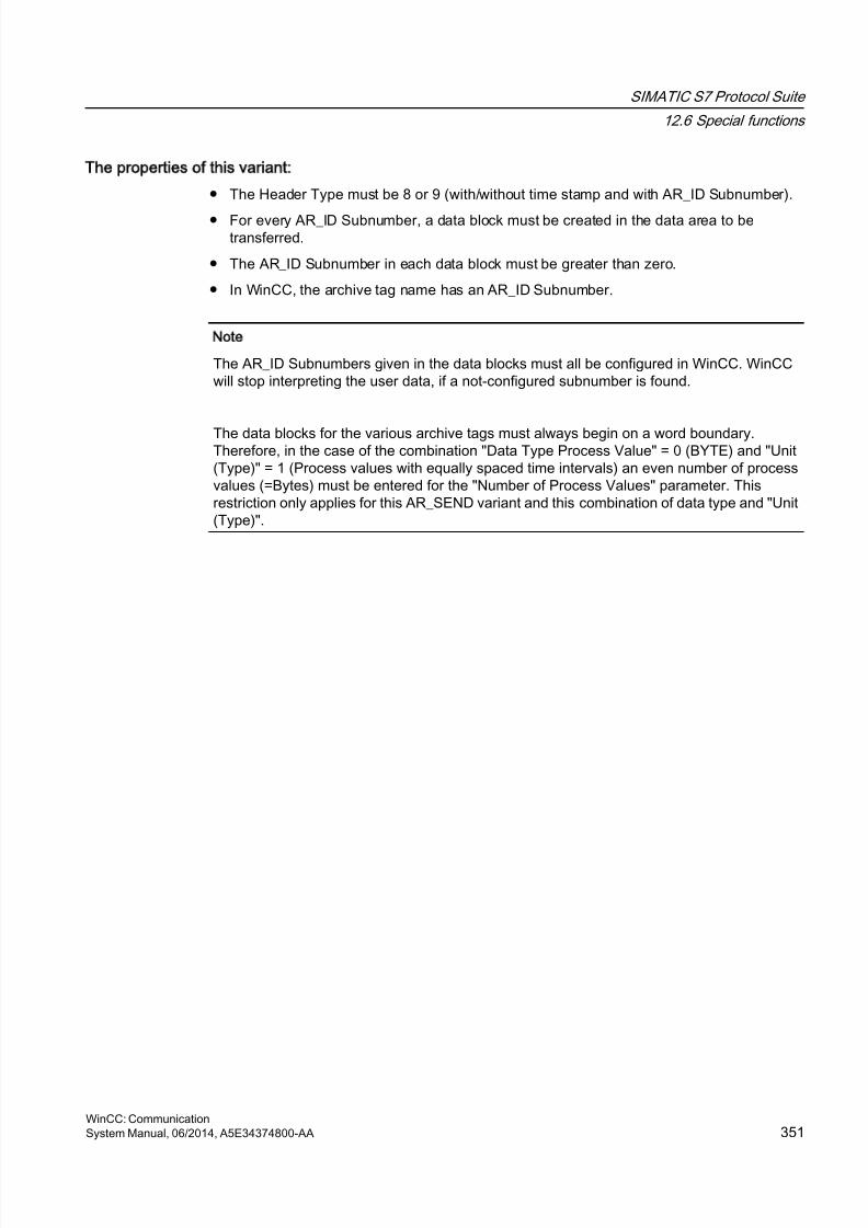
8/20/2019 WinCC Communication en-US en-US
http://slidepdf.com/reader/full/wincc-communication-en-us-en-us 351/527
The properties of this variant:
● The Header Type must be 8 or 9 (with/without time stamp and with AR_ID Subnumber).
● For every AR_ID Subnumber, a data block must be created in the data area to betransferred.
● The AR_ID Subnumber in each data block must be greater than zero.
● In WinCC, the archive tag name has an AR_ID Subnumber.
Note
The AR_ID Subnumbers given in the data blocks must all be configured in WinCC. WinCCwill stop interpreting the user data, if a not-configured subnumber is found.
The data blocks for the various archive tags must always begin on a word boundary.Therefore, in the case of the combination "Data Type Process Value" = 0 (BYTE) and "Unit(Type)" = 1 (Process values with equally spaced time intervals) an even number of processvalues (=Bytes) must be entered for the "Number of Process Values" parameter. Thisrestriction only applies for this AR_SEND variant and this combination of data type and "Unit(Type)".
SIMATIC S7 Protocol Suite
12.6 Special functions
WinCC: CommunicationSystem Manual, 06/2014, A5E34374800-AA 351

8/20/2019 WinCC Communication en-US en-US
http://slidepdf.com/reader/full/wincc-communication-en-us-en-us 352/527
An example of the data area's structure
The data area to be transferred consists of one or more data blocks corresponding to the
number of archive tags to be supplied.
SIMATIC S7 Protocol Suite
12.6 Special functions
WinCC: Communication352 System Manual, 06/2014, A5E34374800-AA
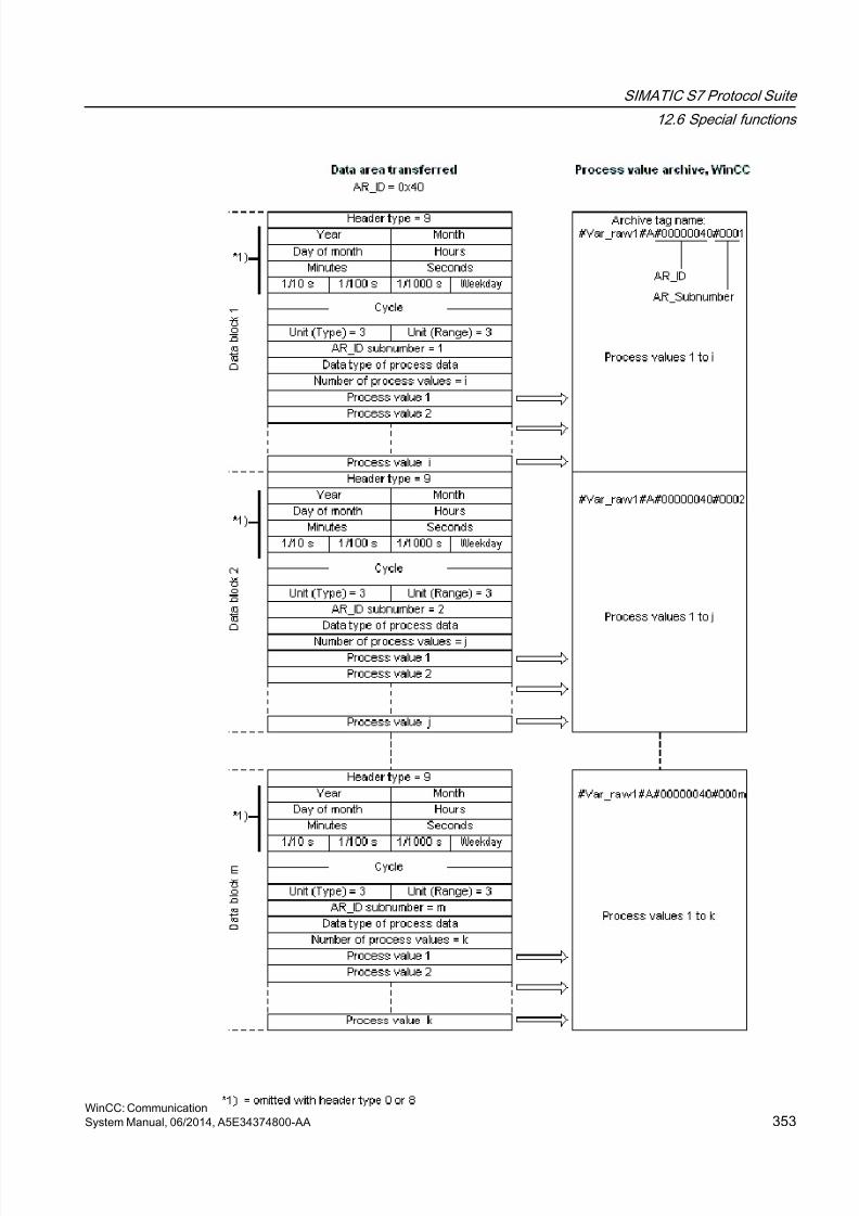
8/20/2019 WinCC Communication en-US en-US
http://slidepdf.com/reader/full/wincc-communication-en-us-en-us 353/527
SIMATIC S7 Protocol Suite
12.6 Special functions
WinCC: CommunicationSystem Manual, 06/2014, A5E34374800-AA 353
8/20/2019 WinCC Communication en-US en-US
http://slidepdf.com/reader/full/wincc-communication-en-us-en-us 354/527
See also
Example 8 for data block structure: Multiple archive tags; process values with relative time
stamp (time difference) (Page 360)Example 7 for data block structure: Multiple archive tags; each process value has its own timestamp (Page 358)
Example 6 for data block structure: Multiple archive tags; equally spaced time stamp (Page 356)
Example 5 for data block structure: Multiple archive tags; each process value has its own timestamp (Page 354)
Overview of the properties of the AR_SEND variants (Page 343)
12.6.2.10 Example 5 for data block structure: Multiple archive tags; each process value has its own
time stamp
Introduction
In this example, process values are transferred for multiple archive tags.
The data blocks for the different archive tags are located one after the other in the datacomponent. A different AR_ID-Subnumber is entered in each data block.
There is no time stamp in the header and the corresponding number of bytes for it are alsonot reserved. Hence, each process value (1byte) is preceded by a time stamp (8byte).
Data type of the process values is BYTE.
SIMATIC S7 Protocol Suite
12.6 Special functions
WinCC: Communication354 System Manual, 06/2014, A5E34374800-AA
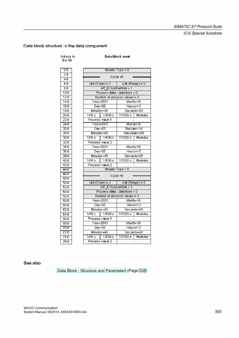
8/20/2019 WinCC Communication en-US en-US
http://slidepdf.com/reader/full/wincc-communication-en-us-en-us 355/527
Data block structure in the data component
See also
Data Block - Structure and Parameters (Page 338)
SIMATIC S7 Protocol Suite
12.6 Special functions
WinCC: CommunicationSystem Manual, 06/2014, A5E34374800-AA 355

8/20/2019 WinCC Communication en-US en-US
http://slidepdf.com/reader/full/wincc-communication-en-us-en-us 356/527
12.6.2.11 Example 6 for data block structure: Multiple archive tags; equally spaced time stamp
Introduction
In this example, process values are transferred for multiple archive tags. The data blocks forthe different archive tags are located one after the other in the data component. A differentAR_ID-Subnumber is entered in the header in each data block.
The equally spaced time stamp of one second is formed using the parameters "Cycle" = 1 and"Unit (Range)" = 4 (= seconds).
Data type of the process values is WORD.
SIMATIC S7 Protocol Suite
12.6 Special functions
WinCC: Communication356 System Manual, 06/2014, A5E34374800-AA
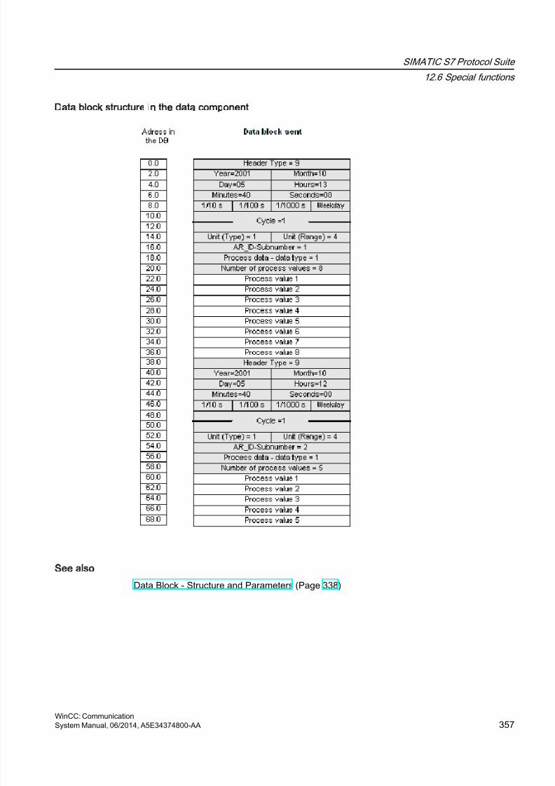
8/20/2019 WinCC Communication en-US en-US
http://slidepdf.com/reader/full/wincc-communication-en-us-en-us 357/527
Data block structure in the data component
See also
Data Block - Structure and Parameters (Page 338)
SIMATIC S7 Protocol Suite
12.6 Special functions
WinCC: CommunicationSystem Manual, 06/2014, A5E34374800-AA 357

8/20/2019 WinCC Communication en-US en-US
http://slidepdf.com/reader/full/wincc-communication-en-us-en-us 358/527
12.6.2.12 Example 7 for data block structure: Multiple archive tags; each process value has its own
time stamp
Introduction
In this example, process values are transferred for multiple archive tags. The data blocks forthe different archive tags are located one after the other in the data component. A differentAR_ID-Subnumber is entered in each data block.
The time stamp in the header is not important. Hence, each process value (1Word) is precededby a time stamp (8byte).
Data type of the process values is SWORD.
SIMATIC S7 Protocol Suite
12.6 Special functions
WinCC: Communication358 System Manual, 06/2014, A5E34374800-AA
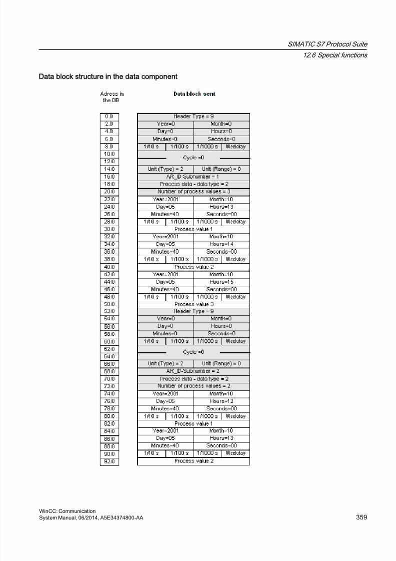
8/20/2019 WinCC Communication en-US en-US
http://slidepdf.com/reader/full/wincc-communication-en-us-en-us 359/527
Data block structure in the data component
SIMATIC S7 Protocol Suite
12.6 Special functions
WinCC: CommunicationSystem Manual, 06/2014, A5E34374800-AA 359
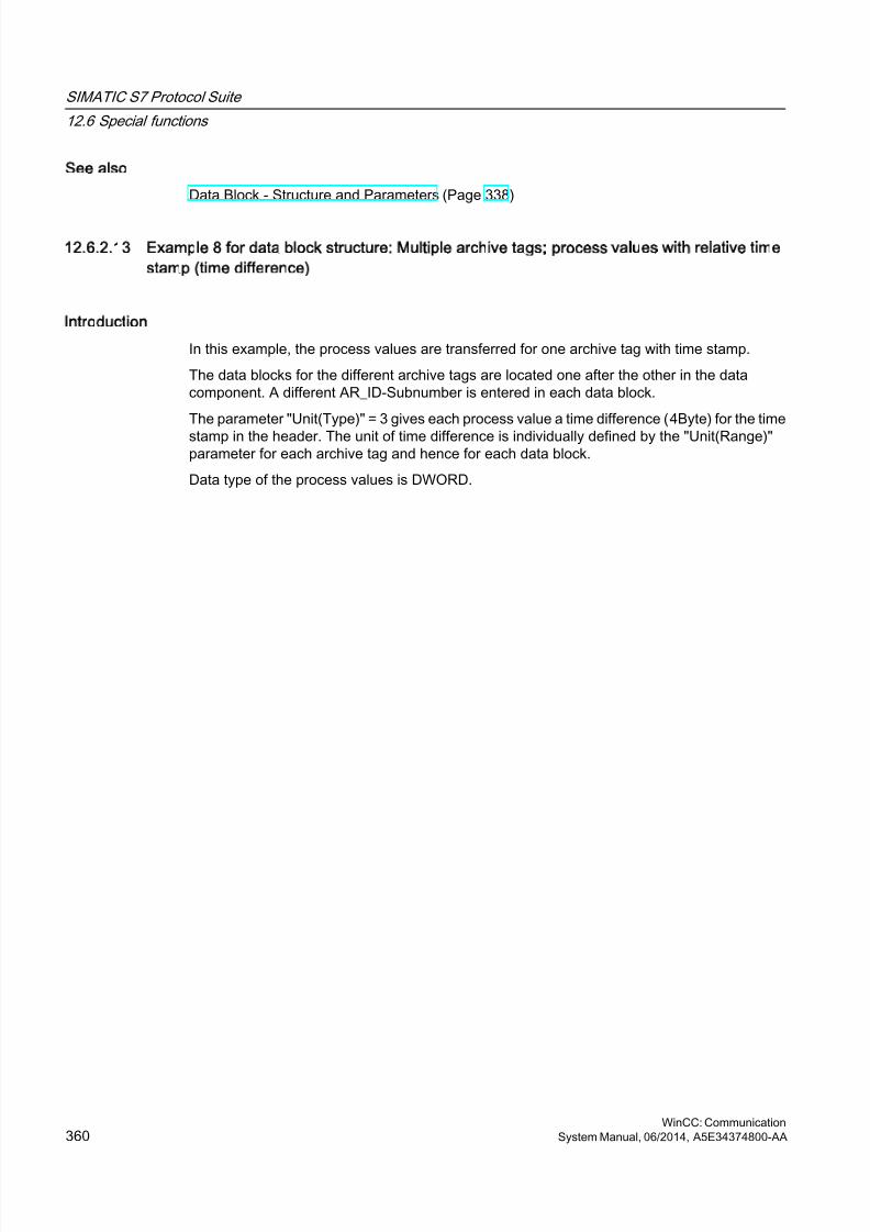
8/20/2019 WinCC Communication en-US en-US
http://slidepdf.com/reader/full/wincc-communication-en-us-en-us 360/527
See also
Data Block - Structure and Parameters (Page 338)
12.6.2.13 Example 8 for data block structure: Multiple archive tags; process values with relative time
stamp (time difference)
Introduction
In this example, the process values are transferred for one archive tag with time stamp.
The data blocks for the different archive tags are located one after the other in the datacomponent. A different AR_ID-Subnumber is entered in each data block.
The parameter "Unit(Type)" = 3 gives each process value a time difference (4Byte) for the time
stamp in the header. The unit of time difference is individually defined by the "Unit(Range)"parameter for each archive tag and hence for each data block.
Data type of the process values is DWORD.
SIMATIC S7 Protocol Suite
12.6 Special functions
WinCC: Communication360 System Manual, 06/2014, A5E34374800-AA
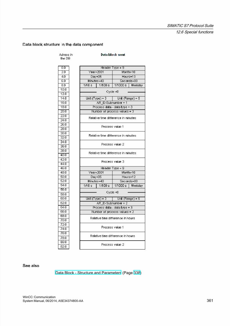
8/20/2019 WinCC Communication en-US en-US
http://slidepdf.com/reader/full/wincc-communication-en-us-en-us 361/527
Data block structure in the data component
See also
Data Block - Structure and Parameters (Page 338)
SIMATIC S7 Protocol Suite
12.6 Special functions
WinCC: CommunicationSystem Manual, 06/2014, A5E34374800-AA 361
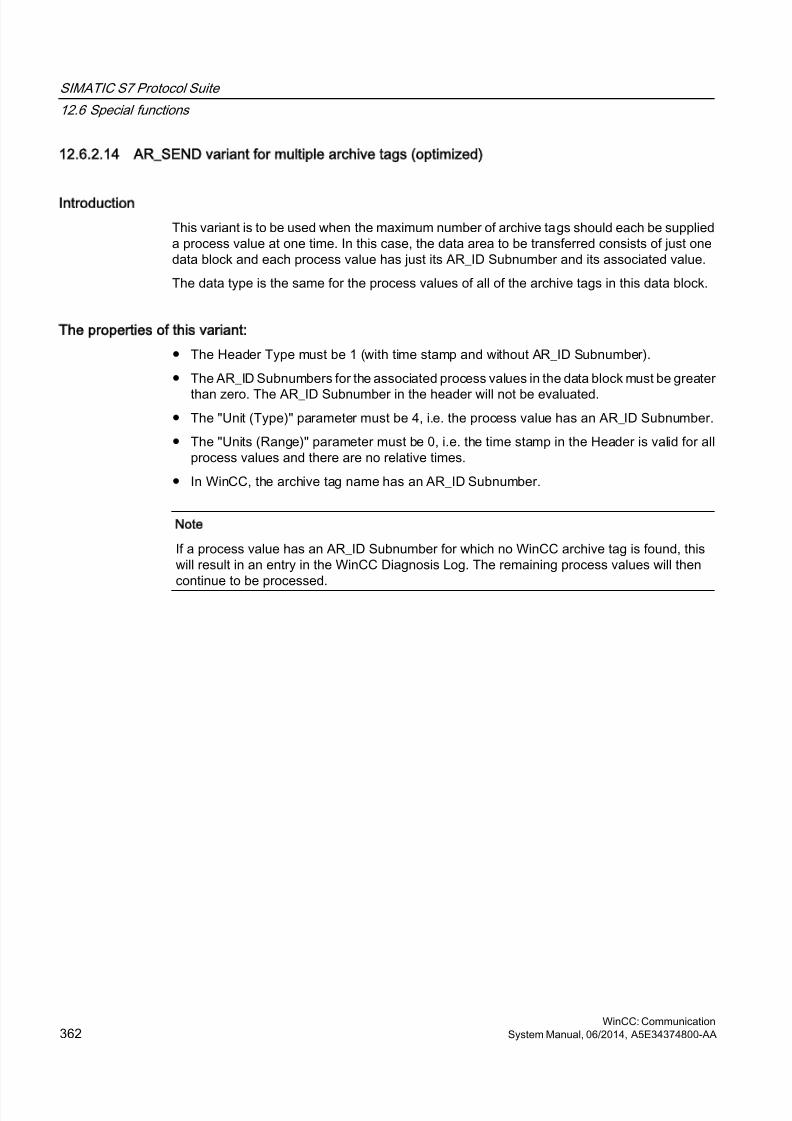
8/20/2019 WinCC Communication en-US en-US
http://slidepdf.com/reader/full/wincc-communication-en-us-en-us 362/527
12.6.2.14 AR_SEND variant for multiple archive tags (optimized)
Introduction
This variant is to be used when the maximum number of archive tags should each be supplieda process value at one time. In this case, the data area to be transferred consists of just onedata block and each process value has just its AR_ID Subnumber and its associated value.
The data type is the same for the process values of all of the archive tags in this data block.
The properties of this variant:
● The Header Type must be 1 (with time stamp and without AR_ID Subnumber).
● The AR_ID Subnumbers for the associated process values in the data block must be greater
than zero. The AR_ID Subnumber in the header will not be evaluated.● The "Unit (Type)" parameter must be 4, i.e. the process value has an AR_ID Subnumber.
● The "Units (Range)" parameter must be 0, i.e. the time stamp in the Header is valid for allprocess values and there are no relative times.
● In WinCC, the archive tag name has an AR_ID Subnumber.
Note
If a process value has an AR_ID Subnumber for which no WinCC archive tag is found, thiswill result in an entry in the WinCC Diagnosis Log. The remaining process values will thencontinue to be processed.
SIMATIC S7 Protocol Suite
12.6 Special functions
WinCC: Communication362 System Manual, 06/2014, A5E34374800-AA
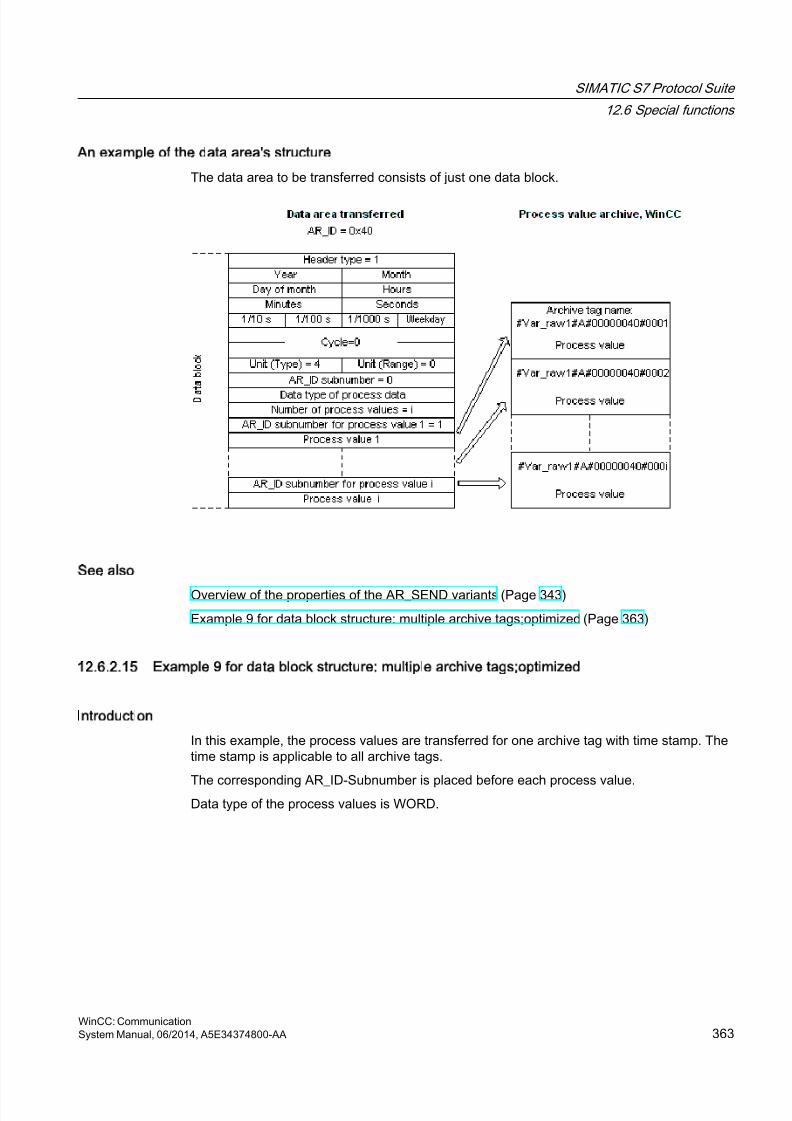
8/20/2019 WinCC Communication en-US en-US
http://slidepdf.com/reader/full/wincc-communication-en-us-en-us 363/527
An example of the data area's structure
The data area to be transferred consists of just one data block.
See also
Overview of the properties of the AR_SEND variants (Page 343)
Example 9 for data block structure: multiple archive tags;optimized (Page 363)
12.6.2.15 Example 9 for data block structure: multiple archive tags;optimized
Introduction
In this example, the process values are transferred for one archive tag with time stamp. Thetime stamp is applicable to all archive tags.
The corresponding AR_ID-Subnumber is placed before each process value.Data type of the process values is WORD.
SIMATIC S7 Protocol Suite
12.6 Special functions
WinCC: CommunicationSystem Manual, 06/2014, A5E34374800-AA 363
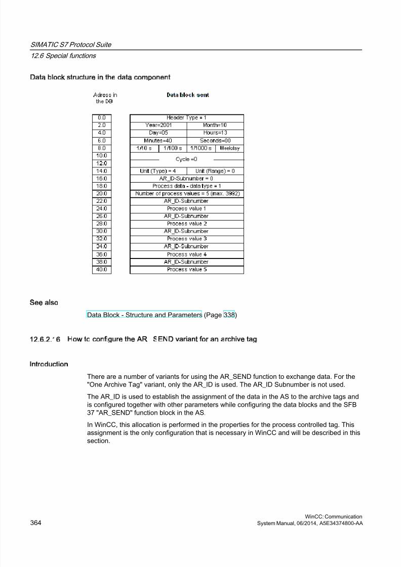
8/20/2019 WinCC Communication en-US en-US
http://slidepdf.com/reader/full/wincc-communication-en-us-en-us 364/527
Data block structure in the data component
See also
Data Block - Structure and Parameters (Page 338)
12.6.2.16 How to configure the AR _SEND variant for an archive tag
Introduction
There are a number of variants for using the AR_SEND function to exchange data. For the"One Archive Tag" variant, only the AR_ID is used. The AR_ID Subnumber is not used.
The AR_ID is used to establish the assignment of the data in the AS to the archive tags andis configured together with other parameters while configuring the data blocks and the SFB37 "AR_SEND" function block in the AS.
In WinCC, this allocation is performed in the properties for the process controlled tag. Thisassignment is the only configuration that is necessary in WinCC and will be described in thissection.
SIMATIC S7 Protocol Suite
12.6 Special functions
WinCC: Communication364 System Manual, 06/2014, A5E34374800-AA
8/20/2019 WinCC Communication en-US en-US
http://slidepdf.com/reader/full/wincc-communication-en-us-en-us 365/527
The other parameters in WinCC need not be configured, since they are evaluatedautomatically.
Note
To use this variant with just the AR_ID, the Header Type must be configure as 0 or 1. TheAR_ID Subnumber must be set to zero.
Since they do not have an AR_ID Subnumber, all of the archive tags, which were configuredbefore WinCC Version V5.0, can be used with this variant.
Since WinCC Version 5.1 Hotfix 4 it has been possible to specify an alias for the archive tagname with process-controlled tags or to use the internal names generated by the system.
The name generated by the system contains the name of the assigned raw data tag insteadof the raw data ID from Version V5.1 HF4. In projects migrated to a version from V5.1 HF4,the archive tag names can be used in their original format or can be converted. The namesare converted by once opening and closing the properties dialog box of the process-controlledarchive tags. An alias does not have to be assigned.
If in a project all external tags are remapped using the "AS-OS-Transfer" function, the archivetag name must therefore be converted once to the new structure! The new structure is thenmaintained.
Requirements
● The "AR_SEND" function block and the data block structure must first be configured in theAS and this configuration information must be available during the following procedure.
● The Channel "SIMATIC S7 Protocol Suite" must be integrated into the project.
● A connection e.g. "Test_Ind_Eth" must be created in a channel unit, e.g. "IndustrialEthernet".
● A process value archive must be configured in the "Tag Logging" editor.
Procedure
1. In the channel "SIMATIC S7 Protocol Suite", select the connection which should be used
for the data transfer.
2. Click the "Tags" tab below the table area.
3. Click in the top free cell of the "Name" column.Enter the name "Var_raw_arsend" for the tag. The name can be no longer than 24characters. The raw data tag name becomes part of the archive tag name during theconfiguration of the process-controlled tag and is therefore limited to this length.
4. Select "Raw Data Type" in the "Data type" field.
5. Open the "Address properties" dialog.For this purpose, click in the "Address" field and then on the button.
SIMATIC S7 Protocol Suite
12.6 Special functions
WinCC: CommunicationSystem Manual, 06/2014, A5E34374800-AA 365
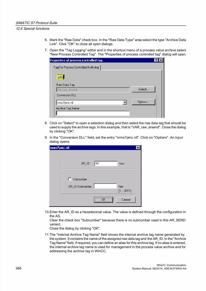
8/20/2019 WinCC Communication en-US en-US
http://slidepdf.com/reader/full/wincc-communication-en-us-en-us 366/527
6. Mark the "Raw Data" check box. In the "Raw Data Type" area select the type "Archive DataLink". Click "OK" to close all open dialogs.
7. Open the "Tag Logging" editor and in the shortcut menu of a process value archive select"New Process Controlled Tag". The "Properties of process controlled tag" dialog will open.
8. Click on "Select" to open a selection dialog and then select the raw data tag that should beused to supply the archive tags. In this example, that is "VAR_raw_arsend". Close the dialogby clicking "OK".
9. In the "Conversion DLL" field, set the entry "nrms7pmc.nll". Click on "Options". An inputdialog opens.
10.Enter the AR_ID as a hexadecimal value. The value is defined through the configuration inthe AS.Clear the check box "Subnumber" because there is no subnumber used in this AR_SENDvariant.Close the dialog by clicking "OK".
11.The "Internal Archive Tag Name" field shows the internal archive tag name generated bythe system. It contains the name of the assigned raw data tag and the AR_ID. In the "ArchiveTag Name" field, if required, you can define an alias for this archive tag. If no alias is entered,the internal archive tag name is used for management in the process value archive and foraddressing the archive tag in WinCC.
SIMATIC S7 Protocol Suite
12.6 Special functions
WinCC: Communication366 System Manual, 06/2014, A5E34374800-AA
8/20/2019 WinCC Communication en-US en-US
http://slidepdf.com/reader/full/wincc-communication-en-us-en-us 367/527
12.Close the dialog by clicking "OK".
13.Save your changes and close Tag Logging.
12.6.2.17 How to configure the AR _SEND variant for multiple archive tags
Introduction
There are a number of variants for using the AR_SEND function to transfer data for multiplearchive tags.
● Use the "Multiple Archive Tags" variant to supply multiple values to multiple archive tagsat various times.
● Use the "Multiple Archive Tags - optimized" variant to supply one value each to the
maximum number of archive tags at one time.The AR_ID and AR_ID Subnumber are used in both of these variants.
AR_ID and AR_ID-Subnumber establish the assignment between the data in the AS and thearchive tag. They are defined in the AS with other parameters when configuring the data blocksand the function module SFB 37 "AR_SEND".
In WinCC, this allocation is performed in the properties for the process controlled tag. Thisassignment is the only configuration that is necessary in WinCC and will be described in thissection.The other parameters in WinCC need not be configured, since they are evaluatedautomatically.
Note
To use the AR_ID Subnumber, the Header Type must be configured as 8 or 9.
Archive tags configured in WinCC Version V5.0 have no AR_ID Subnumber and can thereforeonly be used in the "One Tag" variant.
Since WinCC Version 5.1 Hotfix 4 it has been possible to specify an alias for the archive tagname with process-controlled tags or to use the internal names generated by the system.The name generated by the system contains the name of the assigned raw data tag instead
of the raw data ID from Version V5.1 HF4. In projects migrated to a version from V5.1 HF4,the archive tag names can be used in their original format or can be converted. The namesare converted by once opening and closing the properties dialog box of the process-controlledarchive tags. An alias does not have to be assigned.
If in a project all external tags are remapped using the "AS-OS-Transfer" function, the archivetag name must therefore be converted once to the new structure! The new structure is thenmaintained.
SIMATIC S7 Protocol Suite
12.6 Special functions
WinCC: CommunicationSystem Manual, 06/2014, A5E34374800-AA 367
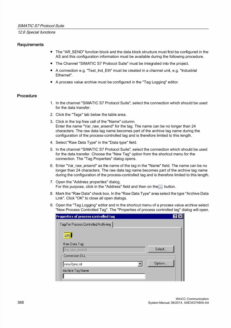
8/20/2019 WinCC Communication en-US en-US
http://slidepdf.com/reader/full/wincc-communication-en-us-en-us 368/527
Requirements
● The "AR_SEND" function block and the data block structure must first be configured in the
AS and this configuration information must be available during the following procedure.● The Channel "SIMATIC S7 Protocol Suite" must be integrated into the project.
● A connection e.g. "Test_Ind_Eth" must be created in a channel unit, e.g. "IndustrialEthernet".
● A process value archive must be configured in the "Tag Logging" editor.
Procedure
1. In the channel "SIMATIC S7 Protocol Suite", select the connection which should be usedfor the data transfer.
2. Click the "Tags" tab below the table area.3. Click in the top free cell of the "Name" column.
Enter the name "Var_raw_arsend" for the tag. The name can be no longer than 24characters. The raw data tag name becomes part of the archive tag name during theconfiguration of the process-controlled tag and is therefore limited to this length.
4. Select "Raw Data Type" in the "Data type" field.
5. In the channel "SIMATIC S7 Protocol Suite", select the connection which should be usedfor the data transfer. Choose the "New Tag" option from the shortcut menu for theconnection. The "Tag Properties" dialog opens.
6. Enter "Var_raw_arsend" as the name of the tag in the "Name" field. The name can be nolonger than 24 characters. The raw data tag name becomes part of the archive tag nameduring the configuration of the process-controlled tag and is therefore limited to this length.
7. Open the "Address properties" dialog.For this purpose, click in the "Address" field and then on the button.
8. Mark the "Raw Data" check box. In the "Raw Data Type" area select the type "Archive DataLink". Click "OK" to close all open dialogs.
9. Open the "Tag Logging" editor and in the shortcut menu of a process value archive select"New Process Controlled Tag". The "Properties of process controlled tag" dialog will open.
SIMATIC S7 Protocol Suite
12.6 Special functions
WinCC: Communication368 System Manual, 06/2014, A5E34374800-AA
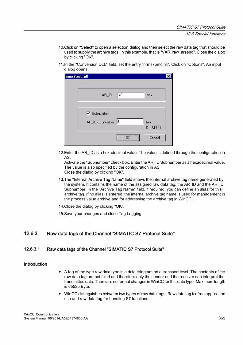
8/20/2019 WinCC Communication en-US en-US
http://slidepdf.com/reader/full/wincc-communication-en-us-en-us 369/527
10.Click on "Select" to open a selection dialog and then select the raw data tag that should beused to supply the archive tags. In this example, that is "VAR_raw_arsend". Close the dialogby clicking "OK".
11.In the "Conversion DLL" field, set the entry "nrms7pmc.nll". Click on "Options". An inputdialog opens.
12.Enter the AR_ID as a hexadecimal value. The value is defined through the configuration inAS.Activate the "Subnumber" check box. Enter the AR_ID Subnumber as a hexadecimal value.The value is also specified by the configuration in AS.Close the dialog by clicking "OK".
13.The "Internal Archive Tag Name" field shows the internal archive tag name generated bythe system. It contains the name of the assigned raw data tag, the AR_ID and the AR_IDSubnumber. In the "Archive Tag Name" field, if required, you can define an alias for thisarchive tag. If no alias is entered, the internal archive tag name is used for management inthe process value archive and for addressing the archive tag in WinCC.
14.Close the dialog by clicking "OK".
15.Save your changes and close Tag Logging.
12.6.3 Raw data tags of the Channel SIMATIC S7 Protocol Suite
12.6.3.1 Raw data tags of the Channel SIMATIC S7 Protocol Suite
Introduction
● A tag of the type raw data type is a data telegram on a transport level. The contents of theraw data tag are not fixed and therefore only the sender and the receiver can interpret thetransmitted data. There are no format changes in WinCC for this data type. Maximum lengthis 65535 Byte.
● WinCC distinguishes between two types of raw data tags: Raw data tag for free applicationuse and raw data tag for handling S7 functions.
SIMATIC S7 Protocol Suite
12.6 Special functions
WinCC: CommunicationSystem Manual, 06/2014, A5E34374800-AA 369
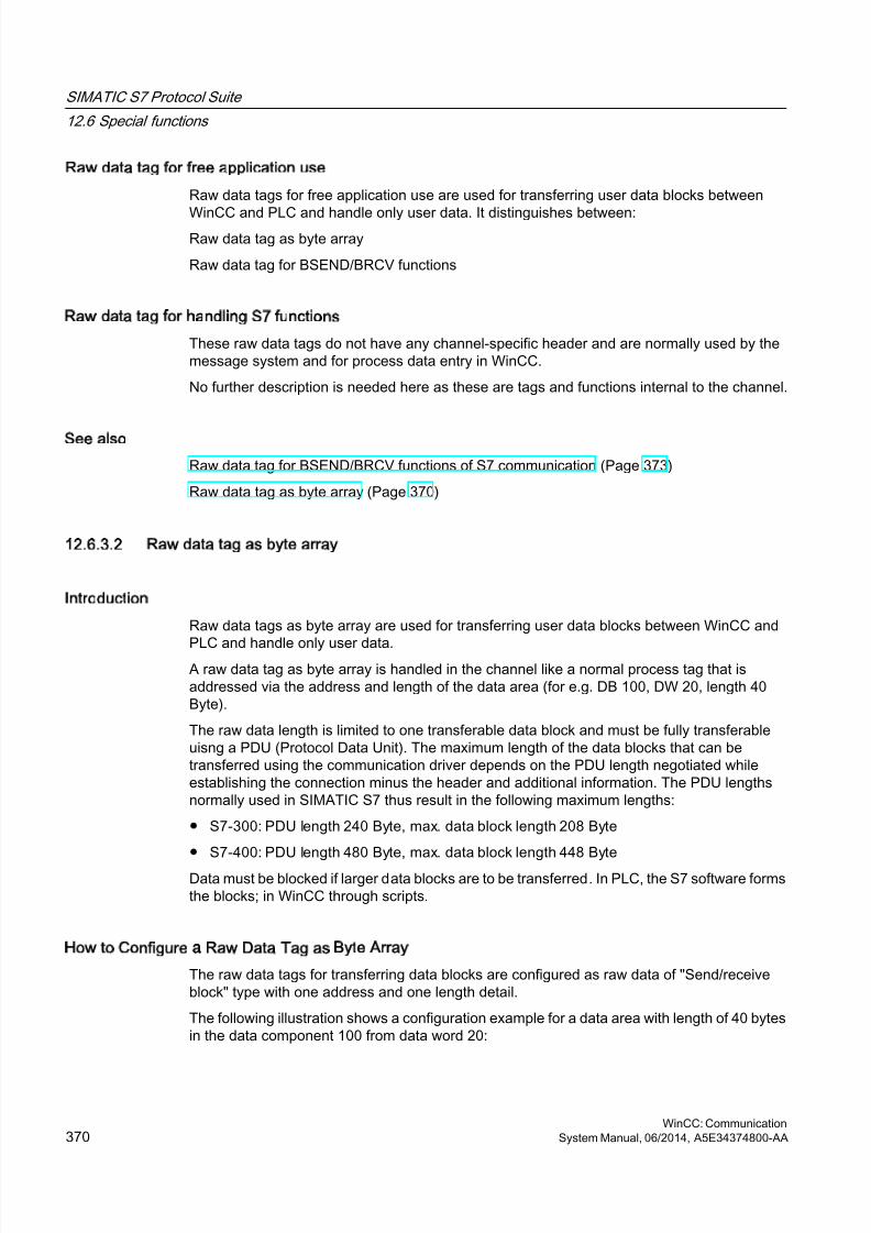
8/20/2019 WinCC Communication en-US en-US
http://slidepdf.com/reader/full/wincc-communication-en-us-en-us 370/527
Raw data tag for free application use
Raw data tags for free application use are used for transferring user data blocks between
WinCC and PLC and handle only user data. It distinguishes between:Raw data tag as byte array
Raw data tag for BSEND/BRCV functions
Raw data tag for handling S7 functions
These raw data tags do not have any channel-specific header and are normally used by themessage system and for process data entry in WinCC.
No further description is needed here as these are tags and functions internal to the channel.
See also
Raw data tag for BSEND/BRCV functions of S7 communication (Page 373)
Raw data tag as byte array (Page 370)
12.6.3.2 Raw data tag as byte array
Introduction
Raw data tags as byte array are used for transferring user data blocks between WinCC and
PLC and handle only user data.A raw data tag as byte array is handled in the channel like a normal process tag that isaddressed via the address and length of the data area (for e.g. DB 100, DW 20, length 40Byte).
The raw data length is limited to one transferable data block and must be fully transferableuisng a PDU (Protocol Data Unit). The maximum length of the data blocks that can betransferred using the communication driver depends on the PDU length negotiated whileestablishing the connection minus the header and additional information. The PDU lengthsnormally used in SIMATIC S7 thus result in the following maximum lengths:
● S7-300: PDU length 240 Byte, max. data block length 208 Byte
● S7-400: PDU length 480 Byte, max. data block length 448 Byte
Data must be blocked if larger data blocks are to be transferred. In PLC, the S7 software formsthe blocks; in WinCC through scripts.
How to Configure a Raw Data Tag as Byte Array
The raw data tags for transferring data blocks are configured as raw data of "Send/receiveblock" type with one address and one length detail.
The following illustration shows a configuration example for a data area with length of 40 bytesin the data component 100 from data word 20:
SIMATIC S7 Protocol Suite
12.6 Special functions
WinCC: Communication370 System Manual, 06/2014, A5E34374800-AA
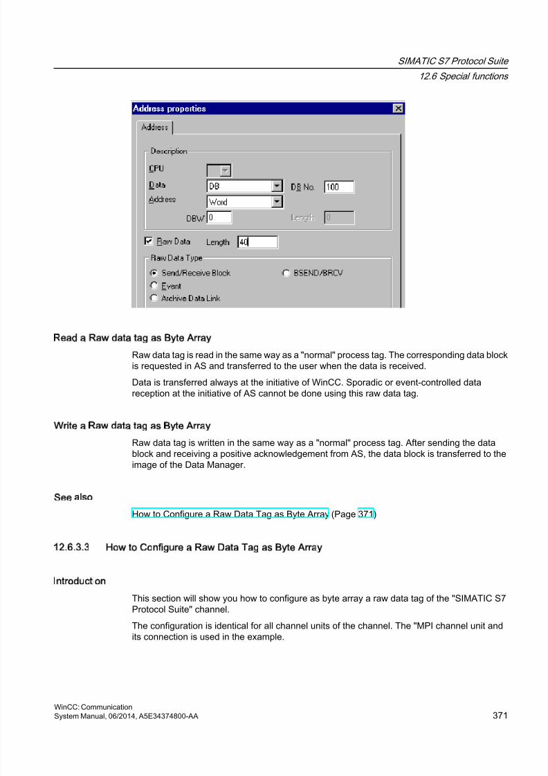
8/20/2019 WinCC Communication en-US en-US
http://slidepdf.com/reader/full/wincc-communication-en-us-en-us 371/527
Read a Raw data tag as Byte Array
Raw data tag is read in the same way as a "normal" process tag. The corresponding data blockis requested in AS and transferred to the user when the data is received.
Data is transferred always at the initiative of WinCC. Sporadic or event-controlled datareception at the initiative of AS cannot be done using this raw data tag.
Write a Raw data tag as Byte Array
Raw data tag is written in the same way as a "normal" process tag. After sending the datablock and receiving a positive acknowledgement from AS, the data block is transferred to theimage of the Data Manager.
See also
How to Configure a Raw Data Tag as Byte Array (Page 371)
12.6.3.3 How to Configure a Raw Data Tag as Byte Array
Introduction
This section will show you how to configure as byte array a raw data tag of the "SIMATIC S7Protocol Suite" channel.
The configuration is identical for all channel units of the channel. The "MPI channel unit andits connection is used in the example.
SIMATIC S7 Protocol Suite
12.6 Special functions
WinCC: CommunicationSystem Manual, 06/2014, A5E34374800-AA 371
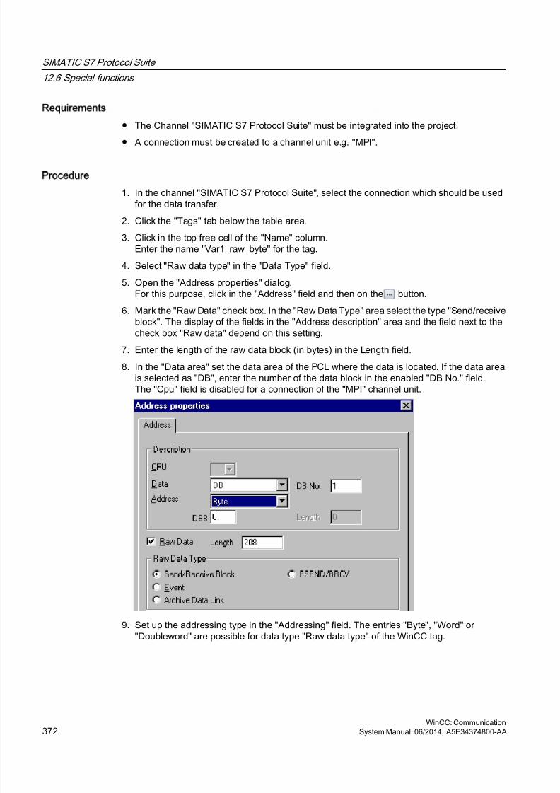
8/20/2019 WinCC Communication en-US en-US
http://slidepdf.com/reader/full/wincc-communication-en-us-en-us 372/527
Requirements
● The Channel "SIMATIC S7 Protocol Suite" must be integrated into the project.
● A connection must be created to a channel unit e.g. "MPI".
Procedure
1. In the channel "SIMATIC S7 Protocol Suite", select the connection which should be usedfor the data transfer.
2. Click the "Tags" tab below the table area.
3. Click in the top free cell of the "Name" column.Enter the name "Var1_raw_byte" for the tag.
4. Select "Raw data type" in the "Data Type" field.
5. Open the "Address properties" dialog.For this purpose, click in the "Address" field and then on the button.
6. Mark the "Raw Data" check box. In the "Raw Data Type" area select the type "Send/receiveblock". The display of the fields in the "Address description" area and the field next to thecheck box "Raw data" depend on this setting.
7. Enter the length of the raw data block (in bytes) in the Length field.
8. In the "Data area" set the data area of the PCL where the data is located. If the data areais selected as "DB", enter the number of the data block in the enabled "DB No." field.The "Cpu" field is disabled for a connection of the "MPI" channel unit.
9. Set up the addressing type in the "Addressing" field. The entries "Byte", "Word" or"Doubleword" are possible for data type "Raw data type" of the WinCC tag.
SIMATIC S7 Protocol Suite
12.6 Special functions
WinCC: Communication372 System Manual, 06/2014, A5E34374800-AA
8/20/2019 WinCC Communication en-US en-US
http://slidepdf.com/reader/full/wincc-communication-en-us-en-us 373/527
10.Enter the value of the start address in the underlying field. The label on the left field dependson the entry in the Data Area and Addressing field, for e.g. "DBB" for data area "DB" "Byte"for addressing type.
11.Click "OK" to close all open dialogs.
Note
The raw data length is limited to one transferable data block and must be fully transferableusing a PDU (Protocol Data Unit). The maximum length of the data block that can betransferred using the communication driver depends on the PDU length negotiated whileestablishing the connection minus the header and additional information. The PDU lengthsnormally used in SIMATIC S7 thus result in the following maximum lengths:
● S7-300: PDU length 240 Byte, max. data block length 208 Byte
● S7-400: PDU length 480 Byte, max. data block length 448 Byte
Wrong length will cause the read/write job to be rejected with a display.
12.6.3.4 Raw data tag for BSEND/BRCV functions of S7 communication
Introduction
Raw data tags for "BSEND/BRCV" functions are used for transferring user data blocks betweenWinCC and AS and handle only user data.
This raw data type can be used to access the "BSEND/BRCV" functions of S7 communication.The functions are available for the following automation systems:
● S7-400
● S7-300
– CPU319-3 PN/DP as of V2.5
– CPU317-2 PN/DP as of V2.6
– CPU315-2 PN/DP as of V3.1
Firmware version V3.x or higher is recommended for S7-300 controllers.● WinAC RTX 2010
The initiative of data transfer always lies with the sending partner; hence "BSEND/BRCV"functions can also be used to implement event-controlled or sporadic data block transfers.
For resource reasons, it is advisable to keep the number of BSEND/BRCV raw data tags low.
Resource limitation for the use of S7 functions AR_SEND and BSEND/BRCV
The maximum data volume that can be sent simultaneously using AR_SEND and/or BSEND/BRCV functions from AS to WinCC is limited:
SIMATIC S7 Protocol Suite
12.6 Special functions
WinCC: CommunicationSystem Manual, 06/2014, A5E34374800-AA 373
8/20/2019 WinCC Communication en-US en-US
http://slidepdf.com/reader/full/wincc-communication-en-us-en-us 374/527
● To 16 KB for the S7-400
● To 8 KB for the S7-300
Examples with the S7-400:
● 1x BSEND with a max. of 16 Kbytes
● 1x AR_SEND with 8 kBytes + 1x BSEND with 8 kBytes
● 1x AR_SEND with 10 Kbytes + 1x AR_SEND with 2 Kbytes + 1x BSEND with 4 Kbytes
Note
If the data block of a write job is transferred to AS and has not yet been deleted or fully deletedfrom the receiving buffer, then the next write job will be rejected with an error message. Duringsuch an error display, write jobs with R_ID > 0x8000 0000 are written to a connection-specific
queue and the system tries to repeat the write job for 6 seconds.The responsibility for time co-ordination for transfer rests with the user and needs to be notedas shorter time intervals for write jobs.
Configuring a PBK Connection for Using BSEND/BRCV functions
"BSEND/BRCV" functions can only be used via a "hard-configured connection", a so-calledPBK connection (programmed component communication). To configure a hard-configuredconnection, you must mention a connection resource (hex: 10 ... DF) in the connectionparameters. This connection resource will be assigned by STEP 7 when the connection isconfigured within the PLC. The connection must be configured as passive connection end-point in the automation system.
A hard-configured connection can also be used to handle "normal" read and write jobs. If verylarge data areas are to be transferred via the connection, then the data blocks are transferredin multiple PDUs. For performance reasons, it would therefore be better to create a separateconnection for "BSEND/BRCV" functions.
SIMATIC S7 Protocol Suite
12.6 Special functions
WinCC: Communication374 System Manual, 06/2014, A5E34374800-AA
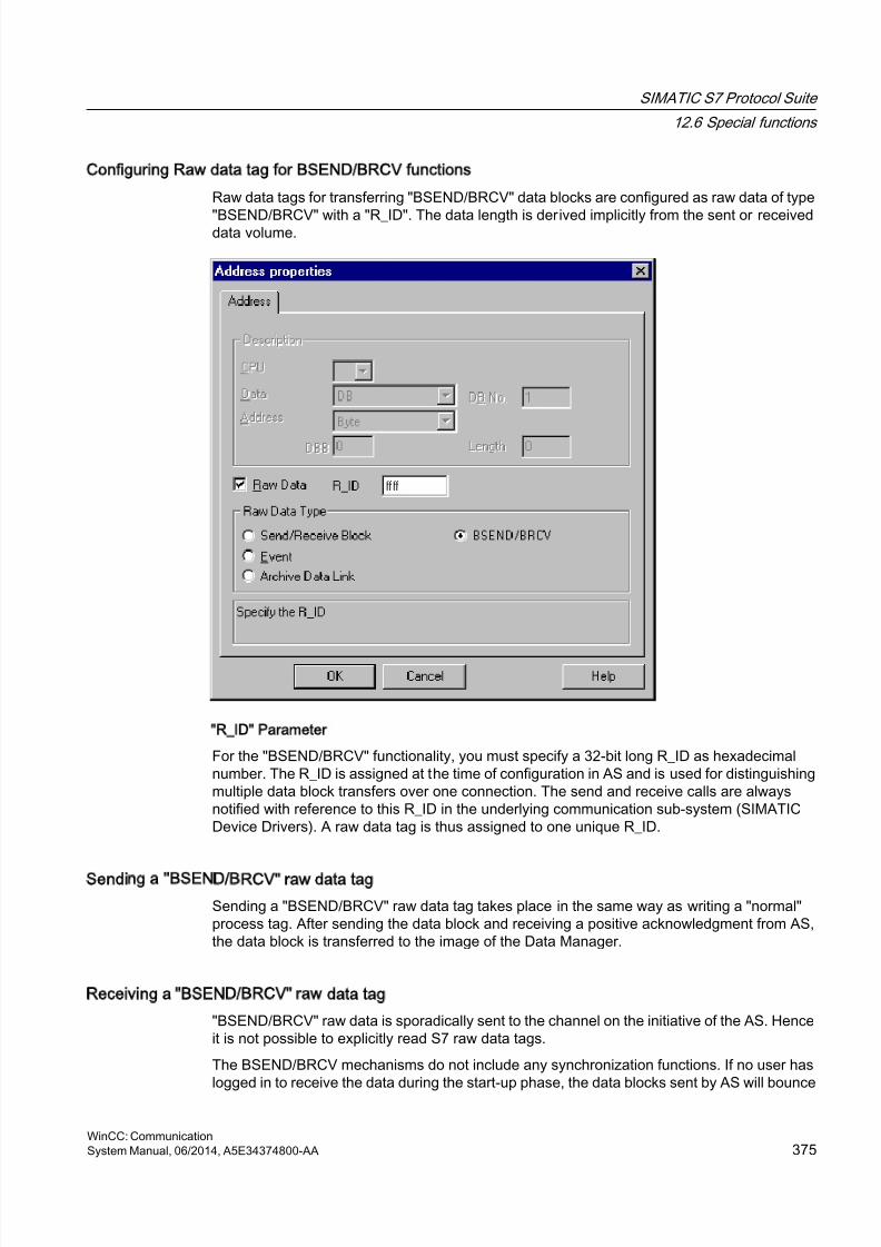
8/20/2019 WinCC Communication en-US en-US
http://slidepdf.com/reader/full/wincc-communication-en-us-en-us 375/527
Configuring Raw data tag for BSEND/BRCV functions
Raw data tags for transferring "BSEND/BRCV" data blocks are configured as raw data of type
"BSEND/BRCV" with a "R_ID". The data length is derived implicitly from the sent or receiveddata volume.
R_ID Parameter
For the "BSEND/BRCV" functionality, you must specify a 32-bit long R_ID as hexadecimalnumber. The R_ID is assigned at the time of configuration in AS and is used for distinguishingmultiple data block transfers over one connection. The send and receive calls are alwaysnotified with reference to this R_ID in the underlying communication sub-system (SIMATICDevice Drivers). A raw data tag is thus assigned to one unique R_ID.
Sending a BSEND/BRCV raw data tag
Sending a "BSEND/BRCV" raw data tag takes place in the same way as writing a "normal"process tag. After sending the data block and receiving a positive acknowledgment from AS,the data block is transferred to the image of the Data Manager.
Receiving a BSEND/BRCV raw data tag
"BSEND/BRCV" raw data is sporadically sent to the channel on the initiative of the AS. Henceit is not possible to explicitly read S7 raw data tags.
The BSEND/BRCV mechanisms do not include any synchronization functions. If no user haslogged in to receive the data during the start-up phase, the data blocks sent by AS will bounce
SIMATIC S7 Protocol Suite
12.6 Special functions
WinCC: CommunicationSystem Manual, 06/2014, A5E34374800-AA 375
8/20/2019 WinCC Communication en-US en-US
http://slidepdf.com/reader/full/wincc-communication-en-us-en-us 376/527
on the receiver side. Hence, the user has to take care of the synchronization and, for e.g.,release the sending direction on the AS by setting a flag with a data word.
See also
How to Configure a Raw Data Tag for ""BSEND/BRCV" functions (Page 376)
12.6.3.5 How to Configure a Raw Data Tag for BSEND/BRCV functions
Introduction
This section will show you how to configure a raw data tag of the "SIMATIC S7 Protocol Suite"channel for "BSEND/BRCV" functions.
The configuration is identical for all channel units of the channel. The "MPI channel unit andits connection is used in the example.
Requirements
● The Channel "SIMATIC S7 Protocol Suite" must be integrated into the project.
● A connection must be created to a channel unit e.g. "MPI".
Procedure
1. In the channel "SIMATIC S7 Protocol Suite", select the connection which should be usedfor the data transfer.
2. Click the "Tags" tab below the table area.
3. Click in the top free cell of the "Name" column.Enter the name "Var2_raw_bsend" for the tag.
4. Select "Raw data type" in the "Data Type" field.
5. Open the "Address properties" dialog.For this purpose, click in the "Address" field and then on the button.
6. Mark the "Raw Data" check box. In the "Raw Data Type" area select the type "BSEND/BRCV". The display of the fields of the "Address description" area is now deactivated.
SIMATIC S7 Protocol Suite
12.6 Special functions
WinCC: Communication376 System Manual, 06/2014, A5E34374800-AA
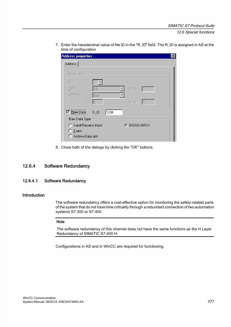
8/20/2019 WinCC Communication en-US en-US
http://slidepdf.com/reader/full/wincc-communication-en-us-en-us 377/527
7. Enter the hexadecimal value of the ID in the "R_ID" field. The R_ID is assigned in AS at thetime of configuration
8. Close both of the dialogs by clicking the "OK" buttons.
12.6.4 Software Redundancy
12.6.4.1 Software Redundancy
Introduction
The software redundancy offers a cost-effective option for monitoring the safety-related partsof the system that do not have time criticality through a redundant connection of two automationsystems S7-300 or S7-400.
Note
The software redundancy of this channel does not have the same functions as the H LayerRedundancy of SIMATIC S7-400 H.
Configurations in AS and in WinCC are required for functioning.
SIMATIC S7 Protocol Suite
12.6 Special functions
WinCC: CommunicationSystem Manual, 06/2014, A5E34374800-AA 377
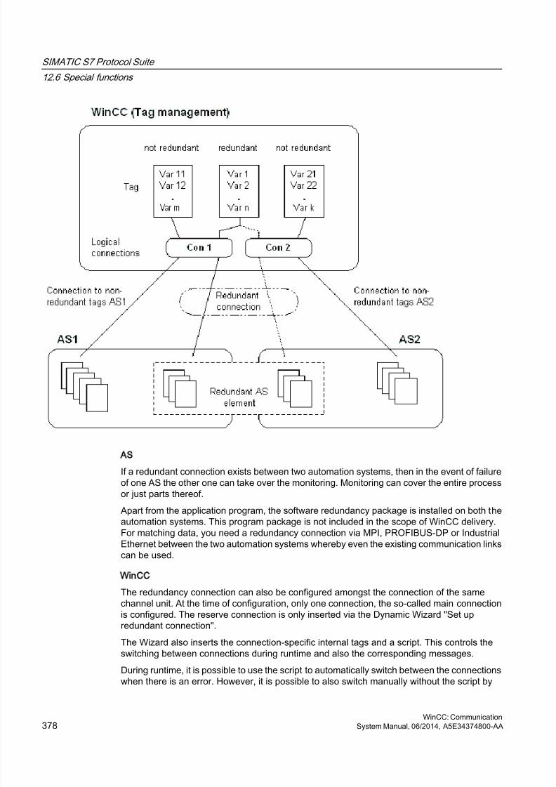
8/20/2019 WinCC Communication en-US en-US
http://slidepdf.com/reader/full/wincc-communication-en-us-en-us 378/527
AS
If a redundant connection exists between two automation systems, then in the event of failureof one AS the other one can take over the monitoring. Monitoring can cover the entire processor just parts thereof.
Apart from the application program, the software redundancy package is installed on both theautomation systems. This program package is not included in the scope of WinCC delivery.For matching data, you need a redundancy connection via MPI, PROFIBUS-DP or IndustrialEthernet between the two automation systems whereby even the existing communication links
can be used.
WinCC
The redundancy connection can also be configured amongst the connection of the samechannel unit. At the time of configuration, only one connection, the so-called main connectionis configured. The reserve connection is only inserted via the Dynamic Wizard "Set upredundant connection".
The Wizard also inserts the connection-specific internal tags and a script. This controls theswitching between connections during runtime and also the corresponding messages.
During runtime, it is possible to use the script to automatically switch between the connectionswhen there is an error. However, it is possible to also switch manually without the script by
SIMATIC S7 Protocol Suite
12.6 Special functions
WinCC: Communication378 System Manual, 06/2014, A5E34374800-AA
8/20/2019 WinCC Communication en-US en-US
http://slidepdf.com/reader/full/wincc-communication-en-us-en-us 379/527
describing the connection-specific internal tags"@<connectionname>@ForceConnectionAddress".
For AS2, you need a second fixed configuration connection if data is to be used from the non-redundant part of AS2 in WinCC.
The use of software redundancy does not means that the hard configured connections canonly be used for the redundancy. Each single connection can also be used without redundance.
See also
How to Clear a Software Redundancy in WinCC (Page 386)
How To Configure a Software Redundancy (Page 383)
Software Redundancy - Connection-specific internal tags (Page 379)
12.6.4.2 Software Redundancy - Connection-specific internal tags
Introduction
Connection-specific internal tags are used to control the redundant connections. These tagsare setup using the Dynamic Wizard "Redundant Connection Configuration" and are gatheredin a Tag Group called "@<connectionname>" in the associated connection.
These tags can be used to determine the connection status and to control the establishmentof a connection. Thus, they can also be used to implement other applications, e.g. theaddressing of multiple PLCs via a single connection. However, if these tags are to be used
without the Software Redundancy package, they must be created manually.
Name Format
The name of a connection-specific internal tag is composed of the name of the associatedconnection and an identifier.
"@<connectionname>@<identifier>"
The connection name is prefixed by a "@" to identify it as a system tag. The identifier is placedas a separator before the connection name.
Example: "@CPU_3@ConnectionState"
<connectionname> = CPU_3
<identifier> = ConnectionState
SIMATIC S7 Protocol Suite
12.6 Special functions
WinCC: CommunicationSystem Manual, 06/2014, A5E34374800-AA 379
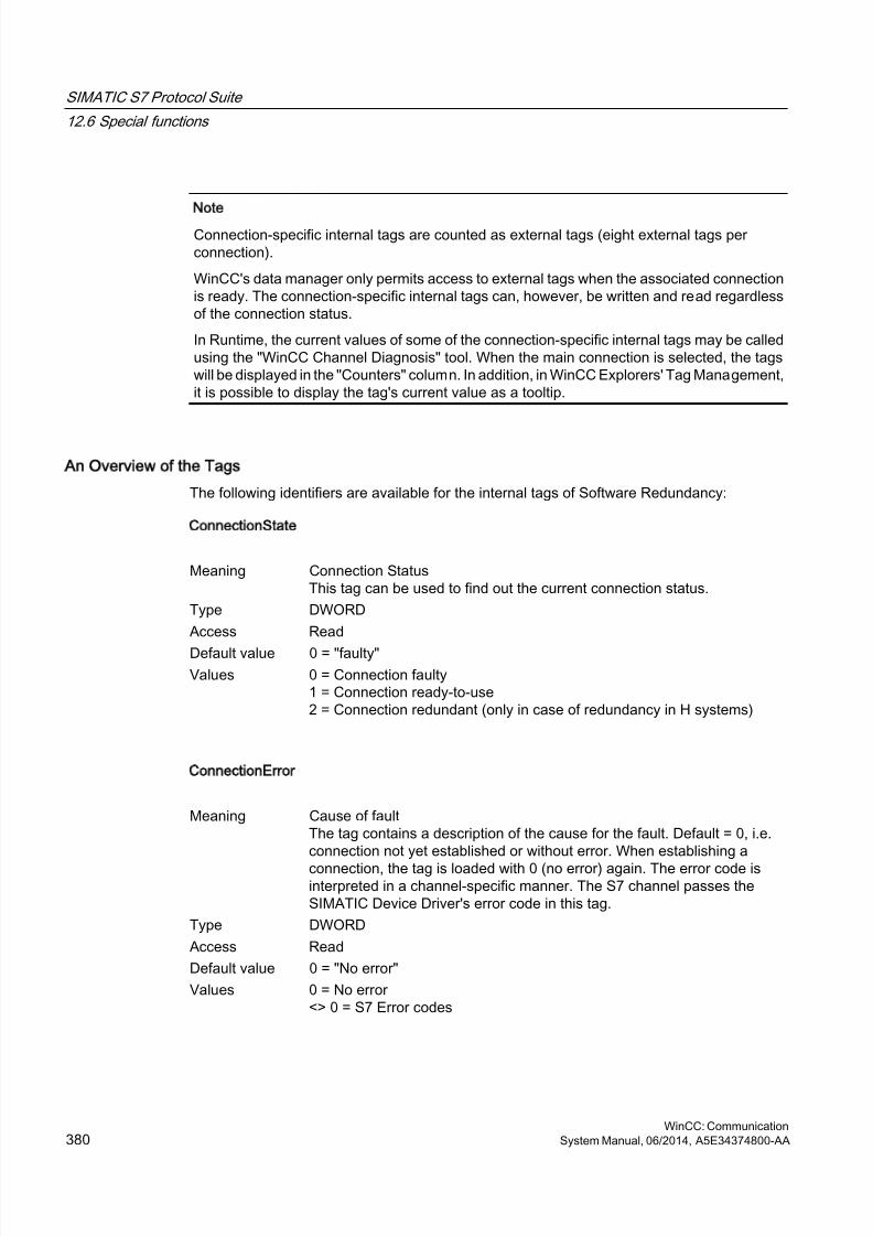
8/20/2019 WinCC Communication en-US en-US
http://slidepdf.com/reader/full/wincc-communication-en-us-en-us 380/527
Note
Connection-specific internal tags are counted as external tags (eight external tags perconnection).
WinCC's data manager only permits access to external tags when the associated connectionis ready. The connection-specific internal tags can, however, be written and read regardlessof the connection status.
In Runtime, the current values of some of the connection-specific internal tags may be calledusing the "WinCC Channel Diagnosis" tool. When the main connection is selected, the tagswill be displayed in the "Counters" column. In addition, in WinCC Explorers' Tag Management,it is possible to display the tag's current value as a tooltip.
An Overview of the Tags
The following identifiers are available for the internal tags of Software Redundancy:
ConnectionState
Meaning Connection StatusThis tag can be used to find out the current connection status.
Type DWORD
Access Read
Default value 0 = "faulty"Values 0 = Connection faulty
1 = Connection ready-to-use2 = Connection redundant (only in case of redundancy in H systems)
ConnectionError
Meaning Cause of faultThe tag contains a description of the cause for the fault. Default = 0, i.e.connection not yet established or without error. When establishing a
connection, the tag is loaded with 0 (no error) again. The error code isinterpreted in a channel-specific manner. The S7 channel passes theSIMATIC Device Driver's error code in this tag.
Type DWORD
Access Read
Default value 0 = "No error"
Values 0 = No error <> 0 = S7 Error codes
SIMATIC S7 Protocol Suite
12.6 Special functions
WinCC: Communication380 System Manual, 06/2014, A5E34374800-AA
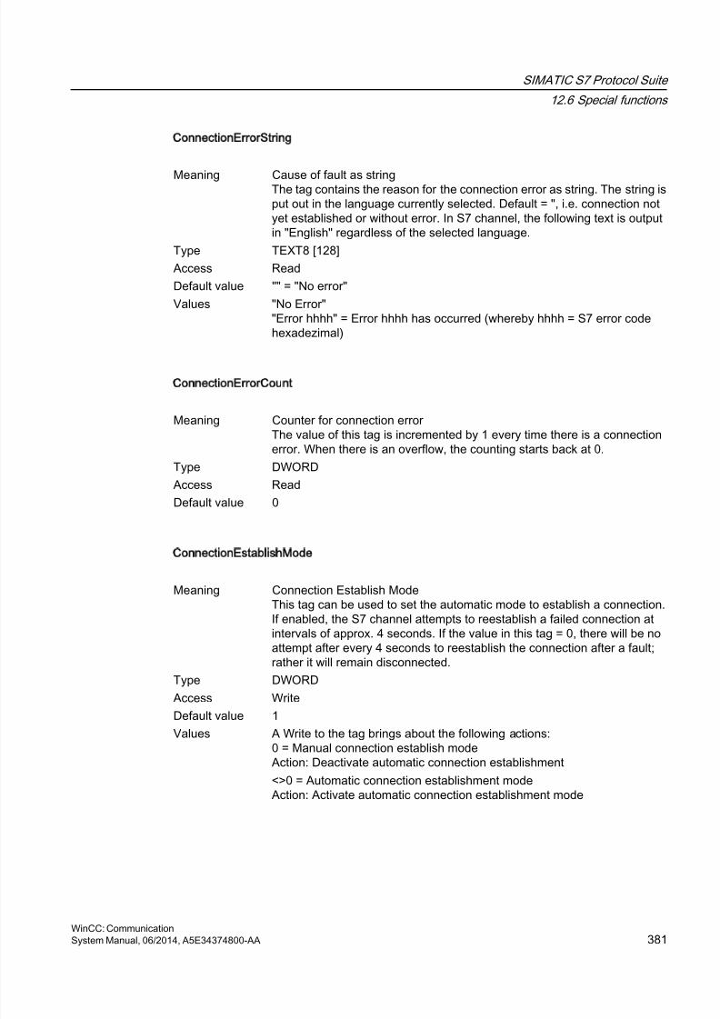
8/20/2019 WinCC Communication en-US en-US
http://slidepdf.com/reader/full/wincc-communication-en-us-en-us 381/527
ConnectionErrorString
Meaning Cause of fault as stringThe tag contains the reason for the connection error as string. The string isput out in the language currently selected. Default = ", i.e. connection notyet established or without error. In S7 channel, the following text is outputin "English" regardless of the selected language.
Type TEXT8 [128]
Access Read
Default value "" = "No error"
Values "No Error""Error hhhh" = Error hhhh has occurred (whereby hhhh = S7 error codehexadezimal)
ConnectionErrorCount
Meaning Counter for connection error The value of this tag is incremented by 1 every time there is a connectionerror. When there is an overflow, the counting starts back at 0.
Type DWORD
Access Read
Default value 0
ConnectionEstablishMode
Meaning Connection Establish ModeThis tag can be used to set the automatic mode to establish a connection.If enabled, the S7 channel attempts to reestablish a failed connection atintervals of approx. 4 seconds. If the value in this tag = 0, there will be noattempt after every 4 seconds to reestablish the connection after a fault;rather it will remain disconnected.
Type DWORD
Access Write
Default value 1Values A Write to the tag brings about the following actions:
0 = Manual connection establish modeAction: Deactivate automatic connection establishment
<>0 = Automatic connection establishment modeAction: Activate automatic connection establishment mode
SIMATIC S7 Protocol Suite
12.6 Special functions
WinCC: CommunicationSystem Manual, 06/2014, A5E34374800-AA 381
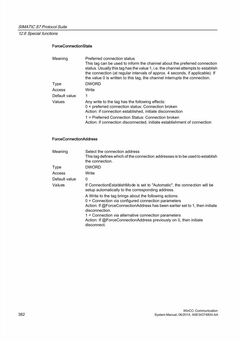
8/20/2019 WinCC Communication en-US en-US
http://slidepdf.com/reader/full/wincc-communication-en-us-en-us 382/527
ForceConnectionState
Meaning Preferred connection statusThis tag can be used to inform the channel about the preferred connectionstatus. Usually this tag has the value 1, i.e. the channel attempts to establishthe connection (at regular intervals of approx. 4 seconds, if applicable). Ifthe value 0 is written to this tag, the channel interrupts the connection.
Type DWORD
Access Write
Default value 1
Values Any write to the tag has the following effects:0 = preferred connection status: Connection brokenAction: if connection established, initiate disconnection
1 = Preferred Connection Status: Connection brokenAction: if connection disconnected, initiate establishment of connection
ForceConnectionAddress
Meaning Select the connection addressThis tag defines which of the connection addresses is to be used to establishthe connection.
Type DWORD
Access Write
Default value 0Values If ConnectionEstablishMode is set to "Automatic", the connection will be
setup automatically to the corresponding address.
A Write to the tag brings about the following actions:0 = Connection via configured connection parametersAction: If @ForceConnectionAddress has been earlier set to 1, then initiatedisconnection.1 = Connection via alternative connection parametersAction: If @ForceConnectionAddress previously on 0, then initiatedisconnect.
SIMATIC S7 Protocol Suite
12.6 Special functions
WinCC: Communication382 System Manual, 06/2014, A5E34374800-AA
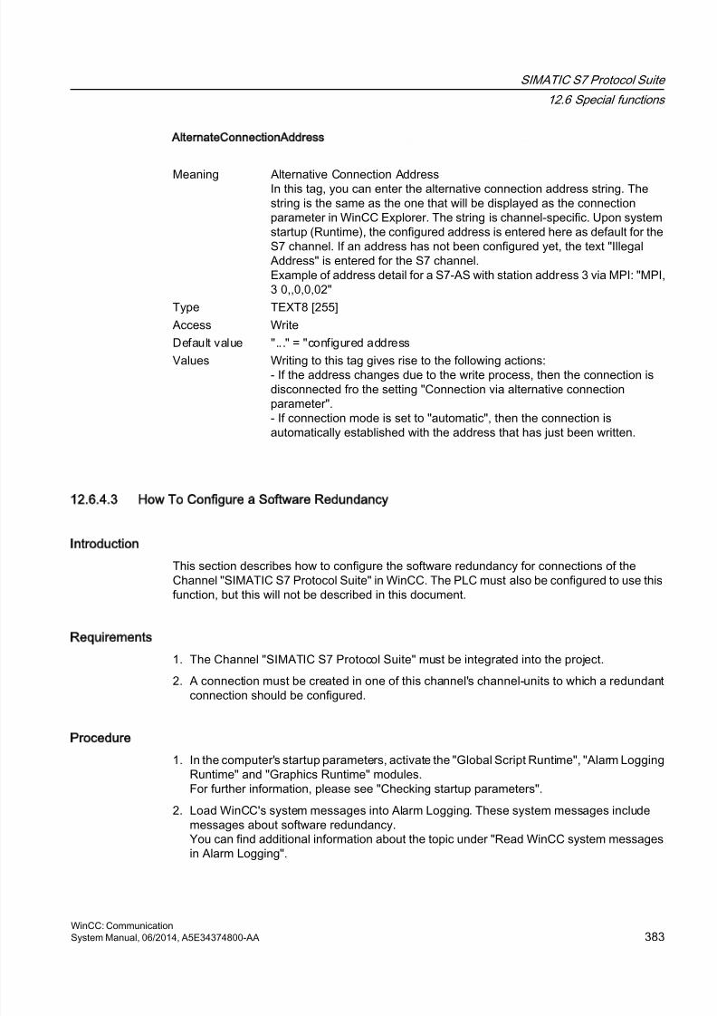
8/20/2019 WinCC Communication en-US en-US
http://slidepdf.com/reader/full/wincc-communication-en-us-en-us 383/527
AlternateConnectionAddress
Meaning Alternative Connection AddressIn this tag, you can enter the alternative connection address string. Thestring is the same as the one that will be displayed as the connectionparameter in WinCC Explorer. The string is channel-specific. Upon systemstartup (Runtime), the configured address is entered here as default for theS7 channel. If an address has not been configured yet, the text "IllegalAddress" is entered for the S7 channel.Example of address detail for a S7-AS with station address 3 via MPI: "MPI,3 0,,0,0,02"
Type TEXT8 [255]
Access Write
Default value "..." = "configured address
Values Writing to this tag gives rise to the following actions:- If the address changes due to the write process, then the connection isdisconnected fro the setting "Connection via alternative connectionparameter".- If connection mode is set to "automatic", then the connection isautomatically established with the address that has just been written.
12.6.4.3 How To Configure a Software Redundancy
Introduction
This section describes how to configure the software redundancy for connections of theChannel "SIMATIC S7 Protocol Suite" in WinCC. The PLC must also be configured to use thisfunction, but this will not be described in this document.
Requirements
1. The Channel "SIMATIC S7 Protocol Suite" must be integrated into the project.
2. A connection must be created in one of this channel's channel-units to which a redundantconnection should be configured.
Procedure
1. In the computer's startup parameters, activate the "Global Script Runtime", "Alarm LoggingRuntime" and "Graphics Runtime" modules.For further information, please see "Checking startup parameters".
2. Load WinCC's system messages into Alarm Logging. These system messages includemessages about software redundancy.You can find additional information about the topic under "Read WinCC system messagesin Alarm Logging".
SIMATIC S7 Protocol Suite
12.6 Special functions
WinCC: CommunicationSystem Manual, 06/2014, A5E34374800-AA 383
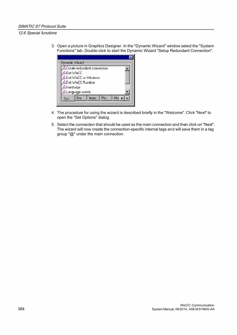
8/20/2019 WinCC Communication en-US en-US
http://slidepdf.com/reader/full/wincc-communication-en-us-en-us 384/527
3. Open a picture in Graphics Designer. In the "Dynamic Wizard" window select the "SystemFunctions" tab. Double-click to start the Dynamic Wizard "Setup Redundant Connection".
4. The procedure for using the wizard is described briefly in the "Welcome". Click "Next" to
open the "Set Options" dialog.5. Select the connection that should be used as the main connection and then click on "Next".
The wizard will now create the connection-specific internal tags and will save them in a taggroup "@" under the main connection.
SIMATIC S7 Protocol Suite
12.6 Special functions
WinCC: Communication384 System Manual, 06/2014, A5E34374800-AA
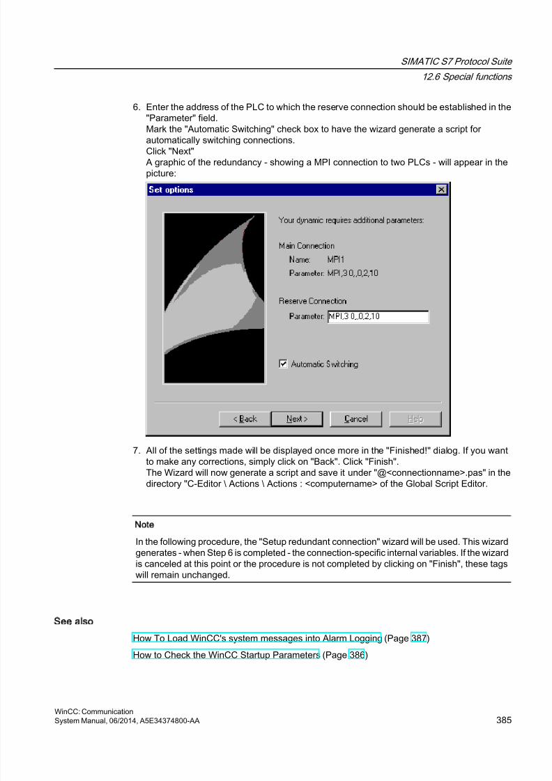
8/20/2019 WinCC Communication en-US en-US
http://slidepdf.com/reader/full/wincc-communication-en-us-en-us 385/527
6. Enter the address of the PLC to which the reserve connection should be established in the"Parameter" field.Mark the "Automatic Switching" check box to have the wizard generate a script for
automatically switching connections.Click "Next"A graphic of the redundancy - showing a MPI connection to two PLCs - will appear in thepicture:
7. All of the settings made will be displayed once more in the "Finished!" dialog. If you wantto make any corrections, simply click on "Back". Click "Finish".The Wizard will now generate a script and save it under "@<connectionname>.pas" in thedirectory "C-Editor \ Actions \ Actions : <computername> of the Global Script Editor.
Note
In the following procedure, the "Setup redundant connection" wizard will be used. This wizardgenerates - when Step 6 is completed - the connection-specific internal variables. If the wizardis canceled at this point or the procedure is not completed by clicking on "Finish", these tagswill remain unchanged.
See also
How To Load WinCC's system messages into Alarm Logging (Page 387)
How to Check the WinCC Startup Parameters (Page 386)
SIMATIC S7 Protocol Suite
12.6 Special functions
WinCC: CommunicationSystem Manual, 06/2014, A5E34374800-AA 385

8/20/2019 WinCC Communication en-US en-US
http://slidepdf.com/reader/full/wincc-communication-en-us-en-us 386/527
12.6.4.4 How to Clear a Software Redundancy in WinCC
Introduction
This section describes how to delete the software redundancy for connections of the Channel"SIMATIC S7 Protocol Suite" in WinCC. The PLC must also be configured to use this functionto return to non-redundant connections, but this is not described in this document.
Requirements
● The WinCC project must be deactivated.
Procedure
A software redundancy is deleted in two steps:
● Delete the tag group "@<computername" including its tags in "Tag Management".
● Delete the script "@<connectionname>.pas" in "Global Script".
Procedure
1. In the Tag Management, select the connection that should be configured as the mainconnection for the software redundancy. It contains a tag group "@<connectionname" withthe software redundancy's connection-specific internal tags. Delete this tag group.
2. Delete the script for the Action "@<connectionname>.pas". To do this, open the C-Editorin "Global Script". Several subdirectories will be displayed.
3. Select the "Actions \ Action : " directory. <computername>". In the data window, delete thescript "@<connectionsname>.pas" for the "Actions" type.
4. Close the "Global Script" editor.
12.6.4.5 How to Check the WinCC Startup Parameters
Procedure
1. In WinCC Explorer, select "Computer".
2. Open the shortcut menu and select "Properties".3. The "Computer List Properties" dialog is opened. Click the "Properties" button.
4. The "Computer Properties" dialog is opened.
5. Click the "Startup" tab and check the entries. If necessary, activate or deactivate Runtimemodules or add other applications to the startup list.
6. Close the open dialogs.
SIMATIC S7 Protocol Suite
12.6 Special functions
WinCC: Communication386 System Manual, 06/2014, A5E34374800-AA

8/20/2019 WinCC Communication en-US en-US
http://slidepdf.com/reader/full/wincc-communication-en-us-en-us 387/527
12.6.4.6 How To Load WinCC's system messages into Alarm Logging
Introduction
In this section you will see how you can load the WinCC system messages into the project.
Procedure
1. Open Alarm Logging.
2. Select the "System Messages" node in the navigation area.
3. You can activate the "Used" option for system messages that you use either in the tablearea or in the Properties area.
4. Select the command "Update used" from the shortcut menu of the "System Messages"node.
12.6.4.7 Error codes during connection disturbances
Documentation of Error Codes
SIMATIC S7 Protocol Suite
12.6 Special functions
WinCC: CommunicationSystem Manual, 06/2014, A5E34374800-AA 387

8/20/2019 WinCC Communication en-US en-US
http://slidepdf.com/reader/full/wincc-communication-en-us-en-us 388/527
8/20/2019 WinCC Communication en-US en-US
http://slidepdf.com/reader/full/wincc-communication-en-us-en-us 389/527
SIMATIC S7-1200, S7-1500 Channel
13
13.1 SIMATIC S7-1200, S7-1500 Channel channel
Introduction
The "SIMATIC S7-1200, S7-1500 Channel" is used for communication between a WinCCstation and the automation systems S7-1200 and S7-1500. The TCP/IP protocol is used forthe communication.
Channel unit
The "SIMATIC S7-1200, S7-1500 Channel" comes with the "OMS+" channel unit.
Recommended communications processors
The following communications processors are recommended for the communication of aWinCC station with the automation systems S7-1200 or S7-1500:
● CP 1612 A2
● CP 1613 A2
● CP 1623
● CP 1628
WinCC: CommunicationSystem Manual, 06/2014, A5E34374800-AA 389
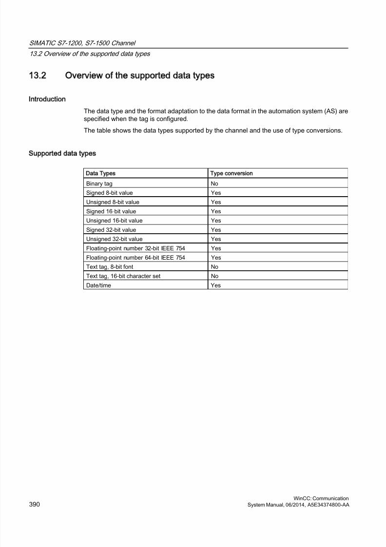
8/20/2019 WinCC Communication en-US en-US
http://slidepdf.com/reader/full/wincc-communication-en-us-en-us 390/527
13.2 Overview of the supported data types
Introduction
The data type and the format adaptation to the data format in the automation system (AS) arespecified when the tag is configured.
The table shows the data types supported by the channel and the use of type conversions.
Supported data types
Data Types Type conversion
Binary tag No
Signed 8-bit value YesUnsigned 8-bit value Yes
Signed 16-bit value Yes
Unsigned 16-bit value Yes
Signed 32-bit value Yes
Unsigned 32-bit value Yes
Floating-point number 32-bit IEEE 754 Yes
Floating-point number 64-bit IEEE 754 Yes
Text tag, 8-bit font No
Text tag, 16-bit character set No
Date/time Yes
SIMATIC S7-1200, S7-1500 Channel
13.2 Overview of the supported data types
WinCC: Communication390 System Manual, 06/2014, A5E34374800-AA
8/20/2019 WinCC Communication en-US en-US
http://slidepdf.com/reader/full/wincc-communication-en-us-en-us 391/527
13.3 Configuring the channel
13.3.1 Configuration of the SIMATIC S7-1200, S7-1500 Channel channel
Introduction
WinCC needs a logical connection for communication of WinCC with the automation system.This section describes how to configure the "SIMATIC S7-1200, S7-1500 Channel".
When using the TCP/IP protocol, you must define the IP address of the automation system forthe logical connection. The IP address consists of four numerical values, separated by dots.The numerical values must be within the range "0-255".
Note
Timeout Behavior
Interrupted connections are not detected immediately when using the TCP/IP protocol. Thecheck-back message can take up to a minute.
Configuring the tags
For a connection between WinCC and the automation system via the "SIMATIC S7-1200,S7-1500 Channel", tags of different data types can be created in WinCC.
The configuration of the tags differs by the addressing of the data area in the automationsystem.
Note
You can only change the configuration of the automation system in the TIA Portal.
13.3.2 How to configure a connection
Introduction
The following steps are required for configuring the "SIMATIC S7-1200, S7-1500 Channel":
1. Configuring a connection
2. Configuring tags
SIMATIC S7-1200, S7-1500 Channel
13.3 Configuring the channel
WinCC: CommunicationSystem Manual, 06/2014, A5E34374800-AA 391
8/20/2019 WinCC Communication en-US en-US
http://slidepdf.com/reader/full/wincc-communication-en-us-en-us 392/527
Requirements
● The communication driver for "SIMATIC S7-1200, S7-1500 Channel" is installed and
integrated into the project.● The SIMATIC project is configured and is available in the automation system.
Procedure
1. Open the menu structure for the "SIMATIC S7-1200, S7-1500 Channel" communicationdriver in the "Tag Management" editor of the WinCC Explorer.
2. Select the entry "New connection" from the shortcut menu of the channel unit "OMS+".
3. Enter the name of the connection.
4. Select the entry "Connection parameters" from the shortcut menu of the connection.
The "New Connection" dialog opens.5. Enter the IP address of the automation system.
6. Select an "Access point".
7. Select an automation system from the "product family".
8. If you want to use password protection, click "Options".
9. Enter the password for access protection.
10.Close both of the dialogs by clicking the "OK" button.
13.3.3 How to configure a tag without optimized block access
Introduction
This section shows you how to configure a tag in WinCC without optimized block access tothe address area in the automation system.
Requirement
● The property "Optimized block access" is deactivated for the data block in the TIA Portal.
● The "SIMATIC S7-1200, S7-1500 Channel" must be integrated into the project.● A connection must be created in the "OMS+" channel unit.
Procedure
1. Select the required connection.
2. Click the "Tags" tab below the table area.
3. Click in the top free cell of the "Name" column. Enter a name for the tag.Configure the following settings in the table area or on the right-hand side in the "Properties- Tags" data area.
SIMATIC S7-1200, S7-1500 Channel
13.3 Configuring the channel
WinCC: Communication392 System Manual, 06/2014, A5E34374800-AA
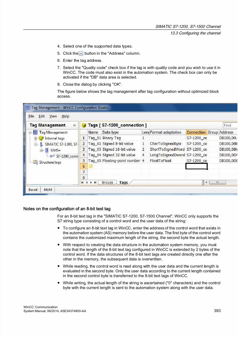
8/20/2019 WinCC Communication en-US en-US
http://slidepdf.com/reader/full/wincc-communication-en-us-en-us 393/527
4. Select one of the supported data types.
5. Click the button in the "Address" column.
6. Enter the tag address.
7. Select the "Quality code" check box if the tag is with quality code and you wish to use it inWinCC. The code must also exist in the automation system. The check box can only beactivated if the "DB" data area is selected.
8. Close the dialog by clicking "OK".
The figure below shows the tag management after tag configuration without optimized blockaccess.
Notes on the configuration of an 8-bit text tag
For an 8-bit text tag in the "SIMATIC S7-1200, S7-1500 Channel", WinCC only supports theS7 string type consisting of a control word and the user data of the string:
● To configure an 8-bit text tag in WinCC, enter the address of the control word that exists inthe automation system (AS) memory before the user data. The first byte of the control word
contains the customized maximum length of the string, the second byte the actual length.
● With respect to creating the data structure in the automation system memory, you mustnote that the length of the 8-bit text tag configured in WinCC is extended by 2 bytes of thecontrol word. If the data structures of the 8-bit text tags are created directly one after theother in the memory, the subsequent data is overwritten.
● While reading, the control word is read along with the user data and the current length isevaluated in the second byte. Only the user data according to the current length containedin the second control byte is transferred to the 8-bit text tags of WinCC.
● While writing, the actual length of the string is ascertained ("0" characters) and the controlbyte with the current length is sent to the automation system along with the user data.
SIMATIC S7-1200, S7-1500 Channel
13.3 Configuring the channel
WinCC: CommunicationSystem Manual, 06/2014, A5E34374800-AA 393
8/20/2019 WinCC Communication en-US en-US
http://slidepdf.com/reader/full/wincc-communication-en-us-en-us 394/527
13.3.4 How to configure a tag with optimized block access
Introduction
This section shows you how to configure a tag in WinCC with optimized block access to theaddress area in the automation system.
Requirement
● The property "Optimized block access" is activated for the data block in the TIA Portal.
● The "SIMATIC S7-1200, S7-1500 Channel" must be integrated into the project.
● A connection must be created in the "OMS+" channel unit.
● The connection must be established in Runtime.
SIMATIC S7-1200, S7-1500 Channel
13.3 Configuring the channel
WinCC: Communication394 System Manual, 06/2014, A5E34374800-AA
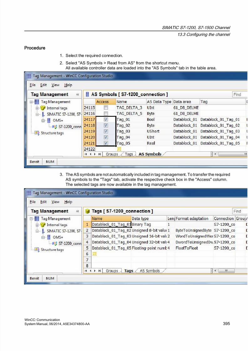
8/20/2019 WinCC Communication en-US en-US
http://slidepdf.com/reader/full/wincc-communication-en-us-en-us 395/527
Procedure
1. Select the required connection.
2. Select "AS Symbols > Read from AS" from the shortcut menu.All available controller data are loaded into the "AS Symbols" tab in the table area.
3. The AS symbols are not automatically included in tag management. To transfer the requiredAS symbols to the "Tags" tab, activate the respective check box in the "Access" column.
The selected tags are now available in the tag management.
SIMATIC S7-1200, S7-1500 Channel
13.3 Configuring the channel
WinCC: CommunicationSystem Manual, 06/2014, A5E34374800-AA 395

8/20/2019 WinCC Communication en-US en-US
http://slidepdf.com/reader/full/wincc-communication-en-us-en-us 396/527
How to edit AS symbols without controller connection
You can configure the controller offline without being connected to it. To do so, you save the
loaded AS symbols in a file.1. Select the required connection.
2. Select "AS Symbols > Save to file" from the shortcut menu of the connection.
You can then load the AS symbols to the tag management in the offline project.
1. Select the required connection.
2. Select "AS Symbols > Load from file" from the shortcut menu of the connection.
SIMATIC S7-1200, S7-1500 Channel
13.3 Configuring the channel
WinCC: Communication396 System Manual, 06/2014, A5E34374800-AA
8/20/2019 WinCC Communication en-US en-US
http://slidepdf.com/reader/full/wincc-communication-en-us-en-us 397/527
SIMATIC TI Ethernet Layer 4
14
14.1 WinCC channel SIMATIC TI Ethernet Layer 4
Introduction
The communication driver "SIMATIC TI Ethernet Layer 4" handles the link between a WinCCstation and a SIMATIC TI505 automation system via Industrial Ethernet. The communicationis handled with the ISO transport protocol.
This chapter describes
● how to configure the data transfer with the "SIMATIC TI Ethernet Layer 4" channel.
● how to configure a connection and a tag.
Channel units
IT has two channel units to run a maximum of two CP 1613. The functionality of the channelunit is identical. They differ only in the logical device names of the two CP 1613.
The logical device name can be changed via the system parameters of the channel unit. Here,it is also possible to set the parameters for the ISO transport protocol.
The following application capabilities exist:
● Channel unit 505 Ethernet (CP 1413-1) for the communication modules for SIMATICIndustrial Ethernet (e.g. CP 1613).
● Channel unit 505 Ethernet (CP 1413-2) for the communication modules for SIMATICIndustrial Ethernet (e.g. CP 1613).
WinCC: CommunicationSystem Manual, 06/2014, A5E34374800-AA 397
8/20/2019 WinCC Communication en-US en-US
http://slidepdf.com/reader/full/wincc-communication-en-us-en-us 398/527
14.2 Data type of the tags
Introduction
Define the required tags for a logical connection. From the WinCC viewpoint, you can accessthe following data types:
● Binary tag
● Unsigned 8 bit value (is only supported by VMS addressing)
● Signed 8 bit value (is only supported by VMS addressing)
● Unsigned 16-bit value
● Signed 16-bit value
● Unsigned 32-bit value● Signed 32-bit value
● Floating-point number 32-bit IEEE 754
● Raw data type
SIMATIC TI Ethernet Layer 4
14.2 Data type of the tags
WinCC: Communication398 System Manual, 06/2014, A5E34374800-AA
8/20/2019 WinCC Communication en-US en-US
http://slidepdf.com/reader/full/wincc-communication-en-us-en-us 399/527
14.3 Configuring the Channel
14.3.1 Configuring the channel SIMATIC TI Ethernet Layer 4
Introduction
The following steps are required for configuring the channel "SIMATIC TI Ethernet Layer 4".
14.3.2 How to configure the connection
Introduction
The process connection via Industrial Ethernet is possible with the SIMATIC TI505 automationsystem. Communication module CP 1434 TF is used in the automation system. Thecommunication is handled with the ISO transport protocol.
The communication module CP 1613 is used in the WinCC system. Because communicationtakes place via the ISO transport protocol, it is not necessary to configure the logical connectionin the local database.
For a logical connection, WinCC establishes one connection in the transport layer for reading(READ) and one for writing (WRITE). Only if both connections are established is the logicalconnection also indicated as being established.
Parameters for the READ function
When configuring the connection, parameters are defined for the READ function in WinCC.These are independent of the request used in the SIMATIC TI.
WinCC side SIMATIC TI side
FETCH-Active(Request "READ-Active")
READ-Passive(Request "READ-Passive")
FETCH-Passive(Request "WRITE-Passive")
WRITE-Active(Request "WRITE-Active")
Parameters Own TSAP-ID and External TSAP-ID for the WRITE function
WinCC side SIMATIC TI side
Request "WRITE Active" Request "WRITE Passive"
SIMATIC TI Ethernet Layer 4
14.3 Configuring the Channel
WinCC: CommunicationSystem Manual, 06/2014, A5E34374800-AA 399
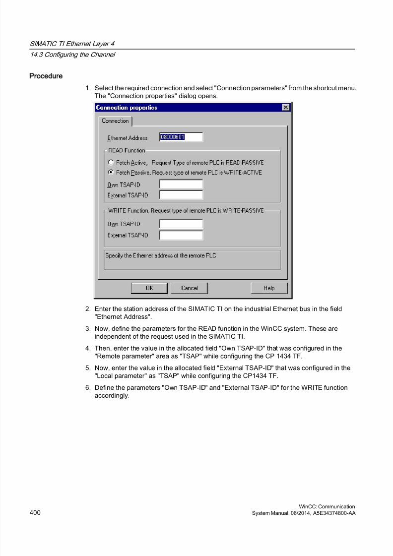
8/20/2019 WinCC Communication en-US en-US
http://slidepdf.com/reader/full/wincc-communication-en-us-en-us 400/527
Procedure
1. Select the required connection and select "Connection parameters" from the shortcut menu.
The "Connection properties" dialog opens.
2. Enter the station address of the SIMATIC TI on the industrial Ethernet bus in the field"Ethernet Address".
3. Now, define the parameters for the READ function in the WinCC system. These areindependent of the request used in the SIMATIC TI.
4. Then, enter the value in the allocated field "Own TSAP-ID" that was configured in the"Remote parameter" area as "TSAP" while configuring the CP 1434 TF.
5. Now, enter the value in the allocated field "External TSAP-ID" that was configured in the"Local parameter" as "TSAP" while configuring the CP1434 TF.
6. Define the parameters "Own TSAP-ID" and "External TSAP-ID" for the WRITE functionaccordingly.
SIMATIC TI Ethernet Layer 4
14.3 Configuring the Channel
WinCC: Communication400 System Manual, 06/2014, A5E34374800-AA
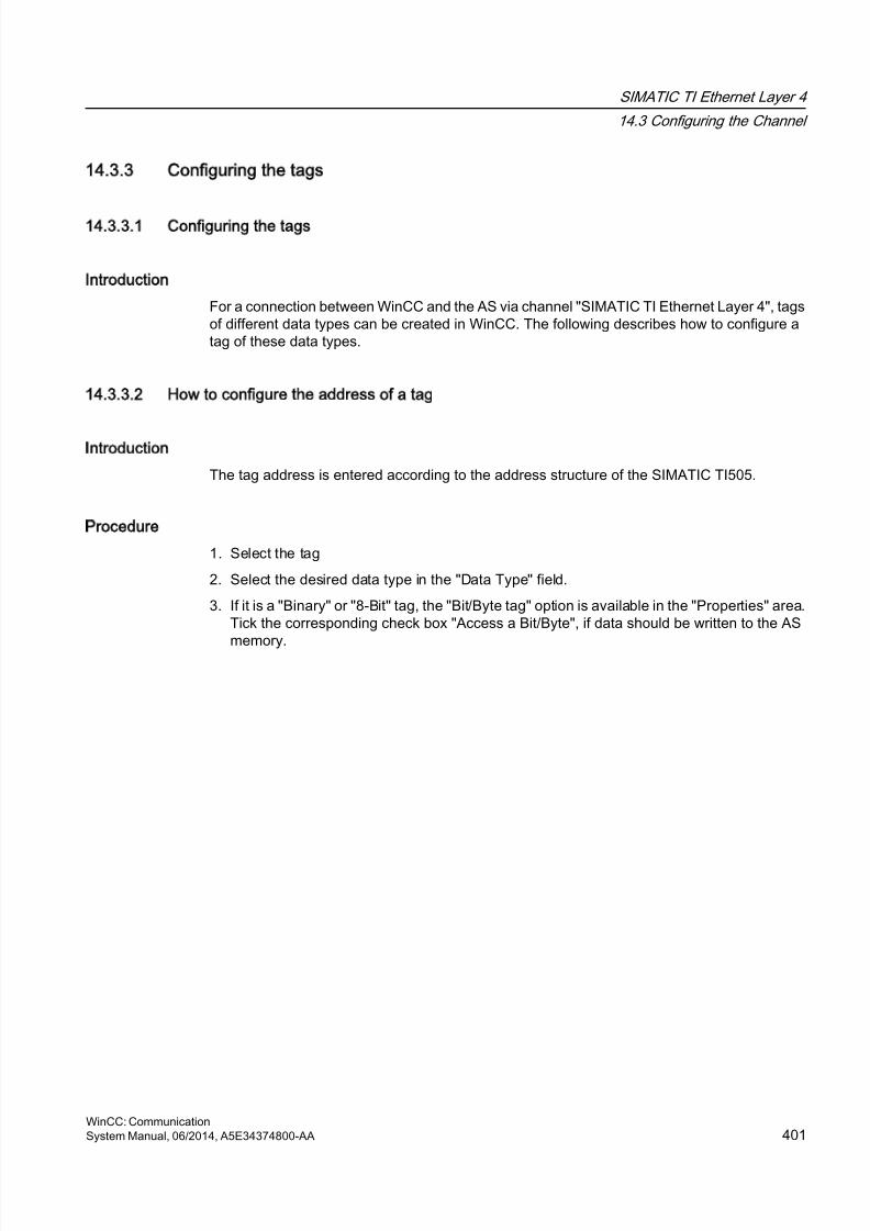
8/20/2019 WinCC Communication en-US en-US
http://slidepdf.com/reader/full/wincc-communication-en-us-en-us 401/527
14.3.3 Configuring the tags
14.3.3.1 Configuring the tags
Introduction
For a connection between WinCC and the AS via channel "SIMATIC TI Ethernet Layer 4", tagsof different data types can be created in WinCC. The following describes how to configure atag of these data types.
14.3.3.2 How to configure the address of a tag
Introduction
The tag address is entered according to the address structure of the SIMATIC TI505.
Procedure
1. Select the tag
2. Select the desired data type in the "Data Type" field.
3. If it is a "Binary" or "8-Bit" tag, the "Bit/Byte tag" option is available in the "Properties" area.Tick the corresponding check box "Access a Bit/Byte", if data should be written to the AS
memory.
SIMATIC TI Ethernet Layer 4
14.3 Configuring the Channel
WinCC: CommunicationSystem Manual, 06/2014, A5E34374800-AA 401
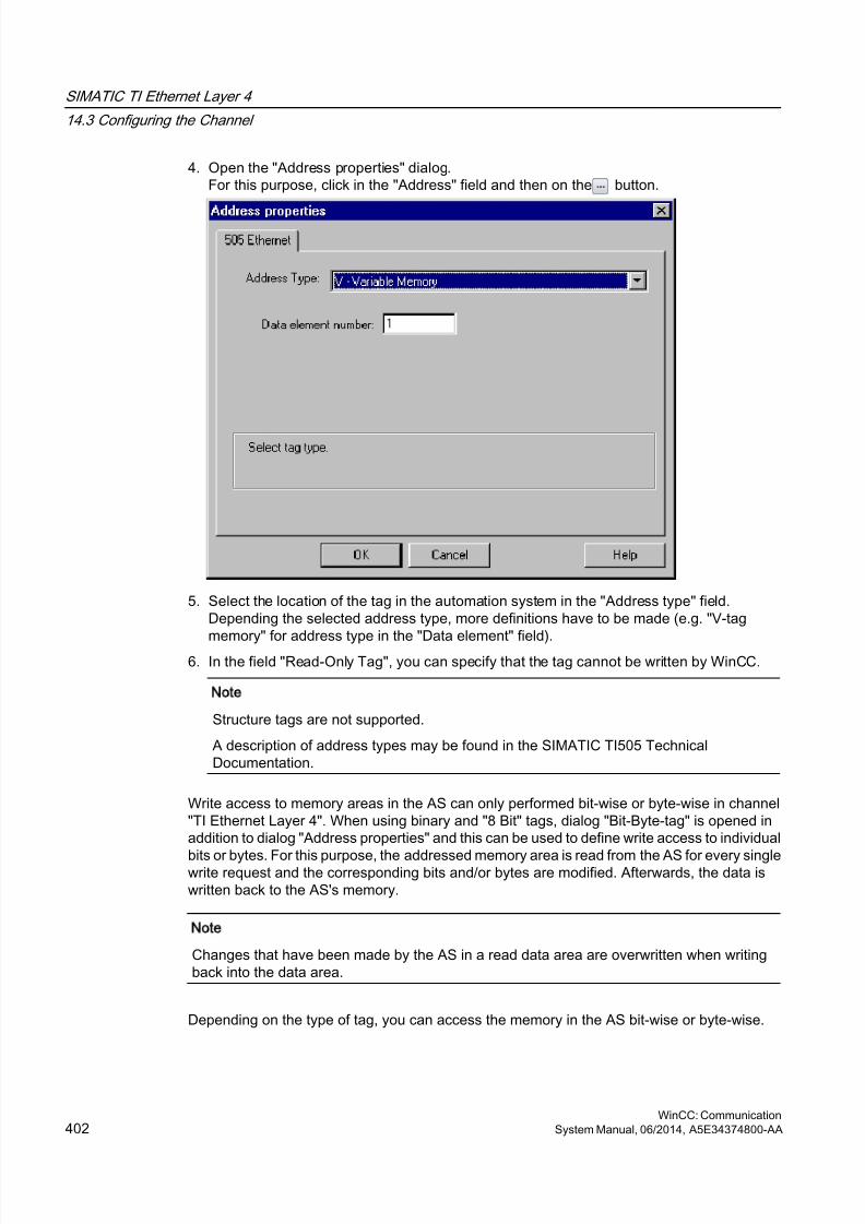
8/20/2019 WinCC Communication en-US en-US
http://slidepdf.com/reader/full/wincc-communication-en-us-en-us 402/527
4. Open the "Address properties" dialog.For this purpose, click in the "Address" field and then on the button.
5. Select the location of the tag in the automation system in the "Address type" field.Depending the selected address type, more definitions have to be made (e.g. "V-tag
memory" for address type in the "Data element" field).6. In the field "Read-Only Tag", you can specify that the tag cannot be written by WinCC.
Note
Structure tags are not supported.
A description of address types may be found in the SIMATIC TI505 TechnicalDocumentation.
Write access to memory areas in the AS can only performed bit-wise or byte-wise in channel"TI Ethernet Layer 4". When using binary and "8 Bit" tags, dialog "Bit-Byte-tag" is opened inaddition to dialog "Address properties" and this can be used to define write access to individual
bits or bytes. For this purpose, the addressed memory area is read from the AS for every singlewrite request and the corresponding bits and/or bytes are modified. Afterwards, the data iswritten back to the AS's memory.
Note
Changes that have been made by the AS in a read data area are overwritten when writingback into the data area.
Depending on the type of tag, you can access the memory in the AS bit-wise or byte-wise.
SIMATIC TI Ethernet Layer 4
14.3 Configuring the Channel
WinCC: Communication402 System Manual, 06/2014, A5E34374800-AA
8/20/2019 WinCC Communication en-US en-US
http://slidepdf.com/reader/full/wincc-communication-en-us-en-us 403/527
14.3.3.3 How to configure a tag with bit-wise access
Introduction
Write access to memory areas in the AS can only performed bit-wise or byte-wise in channel"TI Ethernet Layer 4". When using binary and "8 Bit" tags, dialog "Bit-Byte-tag" is opened inaddition to dialog "Address properties" and this can be used to define write access to individualbits or bytes. For this purpose, the addressed memory area is read from the AS for every singlewrite request and the corresponding bits and/or bytes are modified. Afterwards, the data iswritten back to the AS's memory.
Note
Changes that have been made by the AS in a read data area are overwritten when writingback into the data area.
Procedure
1. Select the tag.
2. Set the "Binary tag" data type in the "Data Type" field.
3. Open the "Bit/Byte tag" dialog.For this purpose, click in the "Address" field and then on the button.
4. Select the "Access to a bit" check box and define the addressing for the bit.
SIMATIC TI Ethernet Layer 4
14.3 Configuring the Channel
WinCC: CommunicationSystem Manual, 06/2014, A5E34374800-AA 403
8/20/2019 WinCC Communication en-US en-US
http://slidepdf.com/reader/full/wincc-communication-en-us-en-us 404/527
5. Click the "Select" button. The "Address properties" dialog is opened.
6. Select the addressing type of the PLC memory in the "Address type" selection field.
7. From the list below, select the number of the element to be changed.
Note
A description of address types may be found in the SIMATIC TI505 Technical Documentation.
14.3.3.4 How to Configure a Tag with Byte by Byte Access
Introduction
Write access to memory areas in the AS can only performed bit-wise or byte-wise in channel"TI Ethernet Layer 4". When using binary and "8 Bit" tags, dialog "Bit-Byte-tag" is opened inaddition to dialog "Address properties" and this can be used to define write access to individualbits or bytes. For this purpose, the addressed memory area is read from the AS for every singlewrite request and the corresponding bits and/or bytes are modified. Afterwards, the data iswritten back to the AS's memory.
Note
Changes that have been made by the AS in a read data area are overwritten when writingback into the data area.
Procedure
1. Select the tag.
2. In the "Data Type" field, set the data type to "Unsigned 8-bit value" or "Signed 8-bit value".
3. Open the "Bit/Byte tag" dialog.For this purpose, click in the "Address" field and then on the button.
SIMATIC TI Ethernet Layer 4
14.3 Configuring the Channel
WinCC: Communication404 System Manual, 06/2014, A5E34374800-AA
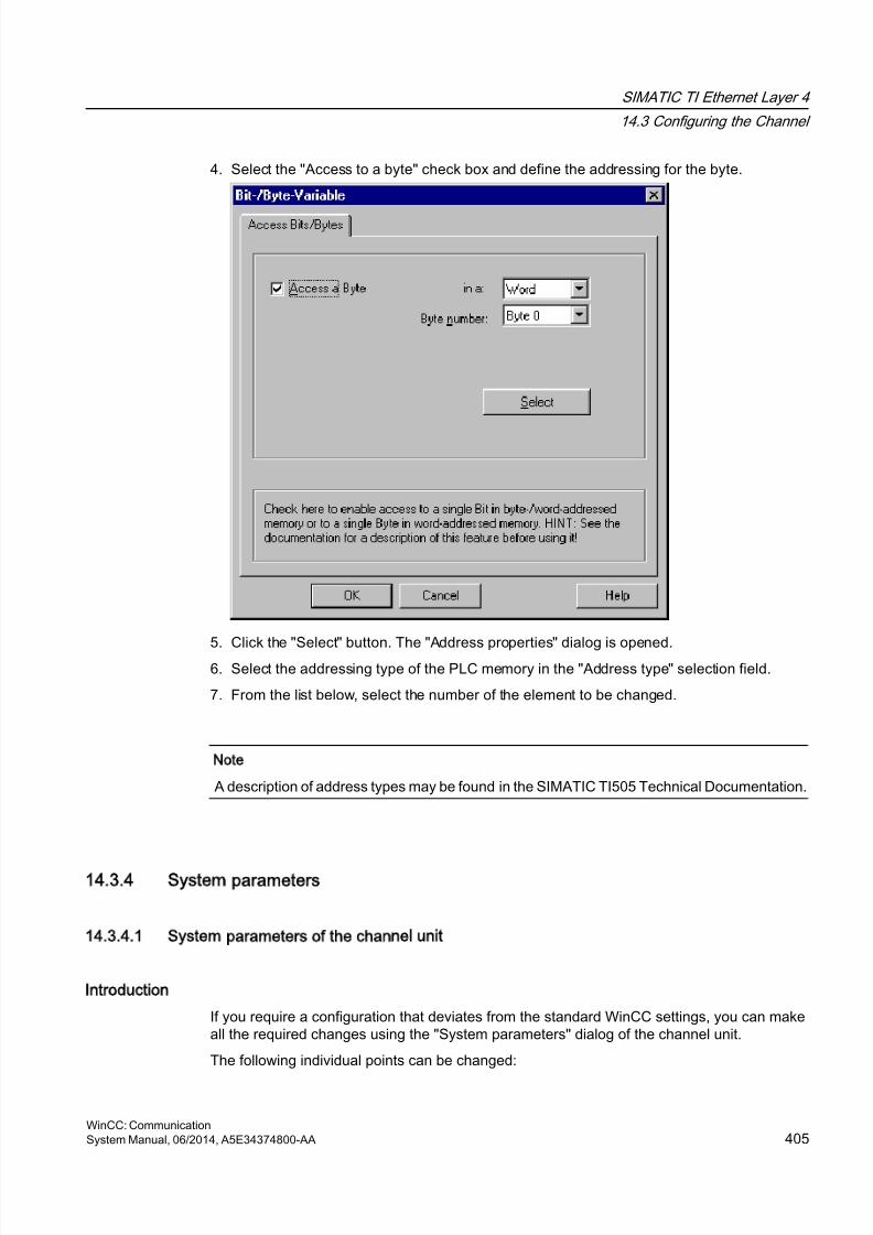
8/20/2019 WinCC Communication en-US en-US
http://slidepdf.com/reader/full/wincc-communication-en-us-en-us 405/527
4. Select the "Access to a byte" check box and define the addressing for the byte.
5. Click the "Select" button. The "Address properties" dialog is opened.6. Select the addressing type of the PLC memory in the "Address type" selection field.
7. From the list below, select the number of the element to be changed.
Note
A description of address types may be found in the SIMATIC TI505 Technical Documentation.
14.3.4 System parameters
14.3.4.1 System parameters of the channel unit
Introduction
If you require a configuration that deviates from the standard WinCC settings, you can makeall the required changes using the "System parameters" dialog of the channel unit.
The following individual points can be changed:
SIMATIC TI Ethernet Layer 4
14.3 Configuring the Channel
WinCC: CommunicationSystem Manual, 06/2014, A5E34374800-AA 405
8/20/2019 WinCC Communication en-US en-US
http://slidepdf.com/reader/full/wincc-communication-en-us-en-us 406/527
● the device name
● the transport parameter
Device Name
Communication between WinCC and the automation system takes place via logical devicenames. These names are assigned during the installation of the communication module andare unit-specific. The device name represents the logical device name. The logical devicename is initially defined as "/CP_H1_1:/SCP" as default.
Transport Parameter
Specific settings for the channel unit are made in the transport parameters, e.g. PDU size,setup attempts, etc.
Note
The system parameters apply for all CPs in the AS.
14.3.4.2 How to Change the Device Name
Introduction
The process connection via Industrial Ethernet is possible with the SIMATIC TI505 automationsystem. Communication module CP 1434 TF is used in the automation system. Thecommunication is handled with the ISO transport protocol.
The communication module CP 1613 is used in the WinCC system. Because communicationtakes place via the ISO transport protocol, it is not necessary to configure the logical connectionin the local database.
SIMATIC TI Ethernet Layer 4
14.3 Configuring the Channel
WinCC: Communication406 System Manual, 06/2014, A5E34374800-AA
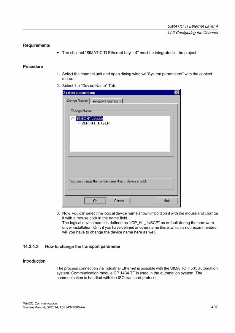
8/20/2019 WinCC Communication en-US en-US
http://slidepdf.com/reader/full/wincc-communication-en-us-en-us 407/527
Requirements
● The channel "SIMATIC TI Ethernet Layer 4" must be integrated in the project.
Procedure
1. Select the channel unit and open dialog window "System parameters" with the contextmenu.
2. Select the "Device Name" Tab.
3. Now, you can select the logical device name shown in bold print with the mouse and changeit with a mouse click in the name field.The logical device name is defined as "/CP_H1_1:/SCP" as default during the hardwaredriver installation. Only if you have defined another name there, which is not recommended,
will you have to change the device name here as well.
14.3.4.3 How to change the transport parameter
Introduction
The process connection via Industrial Ethernet is possible with the SIMATIC TI505 automationsystem. Communication module CP 1434 TF is used in the automation system. Thecommunication is handled with the ISO transport protocol.
SIMATIC TI Ethernet Layer 4
14.3 Configuring the Channel
WinCC: CommunicationSystem Manual, 06/2014, A5E34374800-AA 407
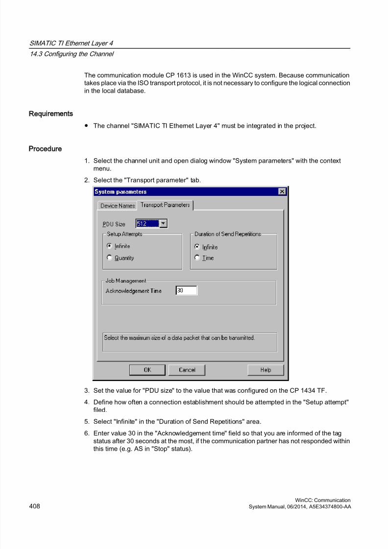
8/20/2019 WinCC Communication en-US en-US
http://slidepdf.com/reader/full/wincc-communication-en-us-en-us 408/527
The communication module CP 1613 is used in the WinCC system. Because communicationtakes place via the ISO transport protocol, it is not necessary to configure the logical connectionin the local database.
Requirements
● The channel "SIMATIC TI Ethernet Layer 4" must be integrated in the project.
Procedure
1. Select the channel unit and open dialog window "System parameters" with the contextmenu.
2. Select the "Transport parameter" tab.
3. Set the value for "PDU size" to the value that was configured on the CP 1434 TF.
4. Define how often a connection establishment should be attempted in the "Setup attempt"filed.
5. Select "Infinite" in the "Duration of Send Repetitions" area.
6. Enter value 30 in the "Acknowledgement time" field so that you are informed of the tagstatus after 30 seconds at the most, if the communication partner has not responded withinthis time (e.g. AS in "Stop" status).
SIMATIC TI Ethernet Layer 4
14.3 Configuring the Channel
WinCC: Communication408 System Manual, 06/2014, A5E34374800-AA
8/20/2019 WinCC Communication en-US en-US
http://slidepdf.com/reader/full/wincc-communication-en-us-en-us 409/527
SIMATIC TI Serial
15
15.1 WinCC channel SIMATIC TI Serial
Introduction
The communication driver "SIMATIC TI Serial" is used for establishing a serial link betweenWinCC station and an SIMATIC TI505 automation device.
This chapter describes
● how to configure the data transfer with the "SIMATIC TI Serial" channel.
● how to configure a connection and a tag.
Channel units
The communication driver has one channel unit for controlling a COM port for the serialconnection.
The following capability is available:
● Channel unit "505 Serial Unit #1" for serial communication, either via the TBP protocol orthe NITP protocol.
Note
It is possible to run more than one logical connections (with different COM ports) throughone channel unit.
WinCC: CommunicationSystem Manual, 06/2014, A5E34374800-AA 409

8/20/2019 WinCC Communication en-US en-US
http://slidepdf.com/reader/full/wincc-communication-en-us-en-us 410/527
15.2 Data type of the tags
Introduction
Define the required tags for a logical connection. From the WinCC viewpoint, you can accessthe following data types:
● Binary tag
● Unsigned 8 bit value (is only supported by VMS addressing)
● Signed 8 bit value (is only supported by VMS addressing)
● Unsigned 16-bit value
● Signed 16-bit value
● Unsigned 32-bit value● Signed 32-bit value
● Floating-point number 32-bit IEEE 754
● Raw data type
SIMATIC TI Serial
15.2 Data type of the tags
WinCC: Communication410 System Manual, 06/2014, A5E34374800-AA
8/20/2019 WinCC Communication en-US en-US
http://slidepdf.com/reader/full/wincc-communication-en-us-en-us 411/527
15.3 Configuring the Channel
15.3.1 Configuring the SIMATIC TI Serial channel
Introduction
The following steps are required for configuring the channel "SIMATIC TI Serial".
15.3.2 How to configure the connection
Introduction
The process connection using a serial connection is possible with the SIMATIC TI505automation system. The serial interface on the CPU module is used in the automation system.
No additional communication module is required in WinCC. Communication can take place bymeans of the default COM ports available on the system.
SIMATIC TI Serial
15.3 Configuring the Channel
WinCC: CommunicationSystem Manual, 06/2014, A5E34374800-AA 411
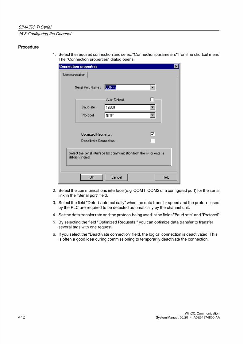
8/20/2019 WinCC Communication en-US en-US
http://slidepdf.com/reader/full/wincc-communication-en-us-en-us 412/527
Procedure
1. Select the required connection and select "Connection parameters" from the shortcut menu.
The "Connection properties" dialog opens.
2. Select the communications interface (e.g. COM1, COM2 or a configured port) for the seriallink in the "Serial port" field.
3. Select the field "Detect automatically" when the data transfer speed and the protocol usedby the PLC are required to be detected automatically by the channel unit.
4. Set the data transfer rate and the protocol being used in the fields "Baud rate" and "Protocol".
5. By selecting the field "Optimized Requests," you can optimize data transfer to transferseveral tags with one request.
6. If you select the "Deactivate connection" field, the logical connection is deactivated. This
is often a good idea during commissioning to temporarily deactivate the connection.
SIMATIC TI Serial
15.3 Configuring the Channel
WinCC: Communication412 System Manual, 06/2014, A5E34374800-AA
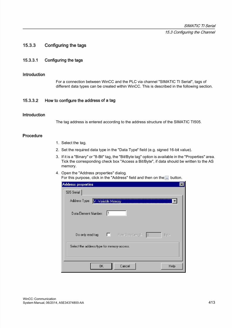
8/20/2019 WinCC Communication en-US en-US
http://slidepdf.com/reader/full/wincc-communication-en-us-en-us 413/527
15.3.3 Configuring the tags
15.3.3.1 Configuring the tags
Introduction
For a connection between WinCC and the PLC via channel "SIMATIC TI Serial", tags ofdifferent data types can be created within WinCC. This is described in the following section.
15.3.3.2 How to configure the address of a tag
Introduction
The tag address is entered according to the address structure of the SIMATIC TI505.
Procedure
1. Select the tag.
2. Set the required data type in the "Data Type" field (e.g. signed 16-bit value).
3. If it is a "Binary" or "8-Bit" tag, the "Bit/Byte tag" option is available in the "Properties" area.Tick the corresponding check box "Access a Bit/Byte", if data should be written to the ASmemory.
4. Open the "Address properties" dialog.For this purpose, click in the "Address" field and then on the button.
SIMATIC TI Serial
15.3 Configuring the Channel
WinCC: CommunicationSystem Manual, 06/2014, A5E34374800-AA 413
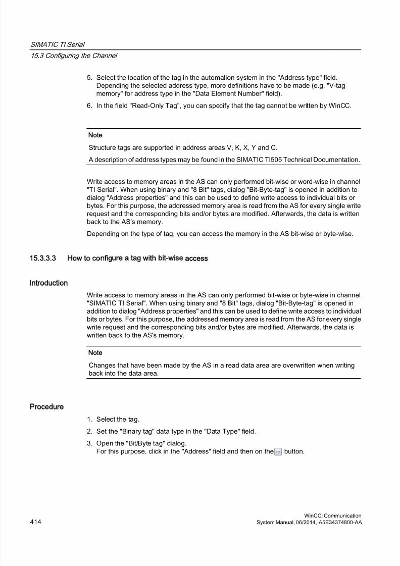
8/20/2019 WinCC Communication en-US en-US
http://slidepdf.com/reader/full/wincc-communication-en-us-en-us 414/527
5. Select the location of the tag in the automation system in the "Address type" field.Depending the selected address type, more definitions have to be made (e.g. "V-tagmemory" for address type in the "Data Element Number" field).
6. In the field "Read-Only Tag", you can specify that the tag cannot be written by WinCC.
Note
Structure tags are supported in address areas V, K, X, Y and C.
A description of address types may be found in the SIMATIC TI505 Technical Documentation.
Write access to memory areas in the AS can only performed bit-wise or word-wise in channel"TI Serial". When using binary and "8 Bit" tags, dialog "Bit-Byte-tag" is opened in addition to
dialog "Address properties" and this can be used to define write access to individual bits orbytes. For this purpose, the addressed memory area is read from the AS for every single writerequest and the corresponding bits and/or bytes are modified. Afterwards, the data is writtenback to the AS's memory.
Depending on the type of tag, you can access the memory in the AS bit-wise or byte-wise.
15.3.3.3 How to configure a tag with bit-wise access
Introduction
Write access to memory areas in the AS can only performed bit-wise or byte-wise in channel"SIMATIC TI Serial". When using binary and "8 Bit" tags, dialog "Bit-Byte-tag" is opened inaddition to dialog "Address properties" and this can be used to define write access to individualbits or bytes. For this purpose, the addressed memory area is read from the AS for every singlewrite request and the corresponding bits and/or bytes are modified. Afterwards, the data iswritten back to the AS's memory.
Note
Changes that have been made by the AS in a read data area are overwritten when writingback into the data area.
Procedure
1. Select the tag.
2. Set the "Binary tag" data type in the "Data Type" field.
3. Open the "Bit/Byte tag" dialog.For this purpose, click in the "Address" field and then on the button.
SIMATIC TI Serial
15.3 Configuring the Channel
WinCC: Communication414 System Manual, 06/2014, A5E34374800-AA
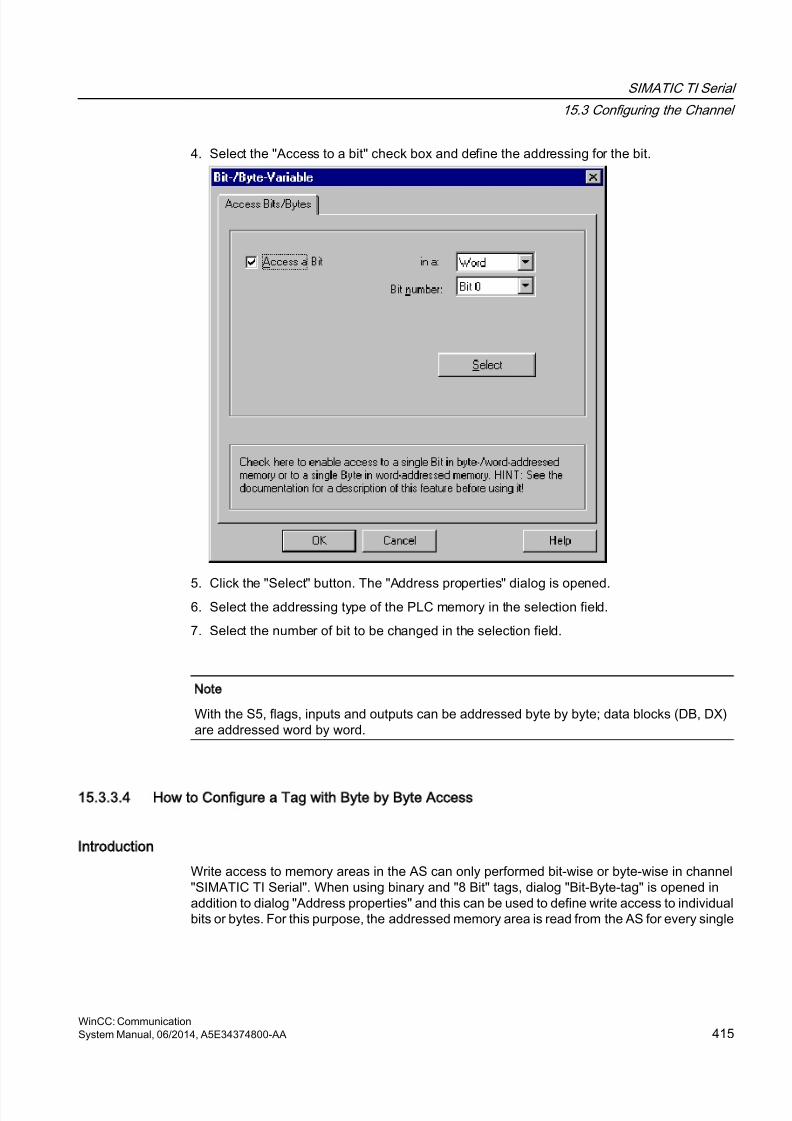
8/20/2019 WinCC Communication en-US en-US
http://slidepdf.com/reader/full/wincc-communication-en-us-en-us 415/527
4. Select the "Access to a bit" check box and define the addressing for the bit.
5. Click the "Select" button. The "Address properties" dialog is opened.6. Select the addressing type of the PLC memory in the selection field.
7. Select the number of bit to be changed in the selection field.
Note
With the S5, flags, inputs and outputs can be addressed byte by byte; data blocks (DB, DX)are addressed word by word.
15.3.3.4 How to Configure a Tag with Byte by Byte Access
Introduction
Write access to memory areas in the AS can only performed bit-wise or byte-wise in channel"SIMATIC TI Serial". When using binary and "8 Bit" tags, dialog "Bit-Byte-tag" is opened inaddition to dialog "Address properties" and this can be used to define write access to individualbits or bytes. For this purpose, the addressed memory area is read from the AS for every single
SIMATIC TI Serial
15.3 Configuring the Channel
WinCC: CommunicationSystem Manual, 06/2014, A5E34374800-AA 415
8/20/2019 WinCC Communication en-US en-US
http://slidepdf.com/reader/full/wincc-communication-en-us-en-us 416/527
write request and the corresponding bits and/or bytes are modified. Afterwards, the data iswritten back to the AS's memory.
Note
Changes that have been made by the AS in a read data area are overwritten when writingback into the data area.
Procedure
1. Select the tag.
2. In the "Data Type" field, set the data type to "Unsigned 8-bit value" or "Signed 8-bit value".
3. Open the "Bit/Byte tag" dialog.For this purpose, click in the "Address" field and then on the button.
4. Select the "Access to a byte" check box and define the addressing for the byte.
5. Click the "Select" button. The "Address properties" dialog is opened.
6. Select the addressing type of the PLC memory in the selection field
7. Select the number of byte to be changed in the selection field.
SIMATIC TI Serial
15.3 Configuring the Channel
WinCC: Communication416 System Manual, 06/2014, A5E34374800-AA
8/20/2019 WinCC Communication en-US en-US
http://slidepdf.com/reader/full/wincc-communication-en-us-en-us 417/527
SIMOTION
16
16.1 WinCC channel SIMOTION
Introduction
The "SIMOTION" channel connects a WinCC station with a SIMOTION automation system.The connection is established via Industrial Ethernet using the TCP/IP protocol.
SIMOTION is a system platform for automation and drive solutions with an emphasis on motioncontrol applications and technology tasks.
The SIMOTION modular system consists of the SIMOTION SCOUT Engineering System anda common runtime system for various hardware platforms.
Export the project from SIMOTION SCOUT to access the data of a SIMOTION SCOUT project..Then create a WinCC project from the exported files with the Simotion Mapper.
You can configure certain changes to the configuration of the SIMOTION automation system,e.g. change an IP address, later in WinCC. Further changes must be configured inSIMOTION SCOUT, exported again and transferred with the Simotion Mapper.
Note
You must be familiar with the SIMOTION SCOUT Engineering System and the configuration
of WinCC to configure the "SIMOTION" channel in WinCC.
WinCC: CommunicationSystem Manual, 06/2014, A5E34374800-AA 417
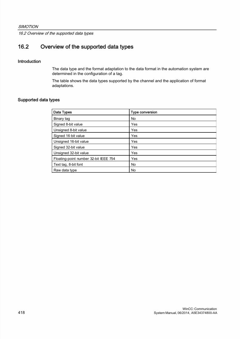
8/20/2019 WinCC Communication en-US en-US
http://slidepdf.com/reader/full/wincc-communication-en-us-en-us 418/527
16.2 Overview of the supported data types
Introduction
The data type and the format adaptation to the data format in the automation system aredetermined in the configuration of a tag.
The table shows the data types supported by the channel and the application of formatadaptations.
Supported data types
Data Types Type conversion
Binary tag NoSigned 8-bit value Yes
Unsigned 8-bit value Yes
Signed 16-bit value Yes
Unsigned 16-bit value Yes
Signed 32-bit value Yes
Unsigned 32-bit value Yes
Floating-point number 32-bit IEEE 754 Yes
Text tag, 8-bit font No
Raw data type No
SIMOTION
16.2 Overview of the supported data types
WinCC: Communication418 System Manual, 06/2014, A5E34374800-AA

8/20/2019 WinCC Communication en-US en-US
http://slidepdf.com/reader/full/wincc-communication-en-us-en-us 419/527
16.3 Configuring the channel
16.3.1 Configuration of the SIMOTION channel
Introduction
This chapter describes how to configure the "SIMOTION" channel.
Note
You must be familiar with the SIMOTION SCOUT Engineering System and the configurationof WinCC to configure the "SIMOTION" channel.
Proceed as follows to configure the "SIMOTION" channel:
1. Export the SIMOTION SCOUT project from SIMOTION SCOUT.
2. Create WinCC project with the Simotion Mapper.
3. Open WinCC project.
4. Configure system parameters.
Further information about the diagnosis of the channel, the connection and the tags can befound in the "Diagnosis 'SIMOTION' channel" chapter.
16.3.2 How to export a SIMOTION SCOUT project
Introduction
This section describes how to export tags and message definitions from SIMOTION SCOUT.
Requirements:
● You are familiar with the SIMOTION SCOUT Engineering System.
● You have access to the SIMOTION SCOUT project to be exported.
Procedure
1. Open the SIMOTION SCOUT project to be exported in SIMOTION SCOUT.
2. Select "Export OPC Data" under "Tools."
SIMOTION
16.3 Configuring the channel
WinCC: CommunicationSystem Manual, 06/2014, A5E34374800-AA 419
8/20/2019 WinCC Communication en-US en-US
http://slidepdf.com/reader/full/wincc-communication-en-us-en-us 420/527
3. Select version "SIMATIC NET V6.4", the desired scope and at least the "OPC-Alarm/Event"option for the export.
Note
Simotion Mapper does not process other export versions than "SIMATIC NET V6.4".
4. Select the destination directory.
5. Select the communication interface.The project is exported.
6. Enter the routing information if you are using routing.
The SIMOTION SCOUT project is exported. The "OPC_Data.sti" and "OPC_AE.xml" files aresaved in the destination directory.
16.3.3 How to create a WinCC project with Simotion Mapper
Introduction
This section describes how to create a WinCC project from the exported SIMOTION SCOUTproject with the Simotion Mapper.
Note
If a WinCC project was already created for an older version of the SIMOTION SCOUT project,
only the SIMOTION parameters are changed in a transmission. All other configurationsettings in the WinCC project (such as archiving) remain the same.
Requirements:
● You have access to the export files "OPC_Data.sti" and "OPC_AE.xml" of theSIMOTION SCOUT project.
● You have access rights to the WinCC installation directory.
Note
In the SIMOTION SCOUT programming environment, the tags to be exported can befiltered using the watch tables. Use the watch tables to keep the number of tags in theWinCC project low. More information on the watch tables can be found in the SIMOTIONSCOUT online help.
Procedure
1. Launch the "SimotionMapper.exe" program in the WinCC installation directory.
2. Click "Open". Navigate to the directory with the files "OPC_Data.sti" and "OPC_AE.xml".The data is read and displayed in Simotion Mapper.
SIMOTION
16.3 Configuring the channel
WinCC: Communication420 System Manual, 06/2014, A5E34374800-AA
8/20/2019 WinCC Communication en-US en-US
http://slidepdf.com/reader/full/wincc-communication-en-us-en-us 421/527
3. In the Simotion Mapper Explorer, select the groups and tags you need in your WinCCproject.
4. Select "Create new WinCC project".5. If you want to change the "WinCC connection name", click on the name displayed and enter
the new name.
6. Specify the "First TA message number" for the technological alarm. The value must beselected in such a way that it does not lead to collisions with messages of othercommunication channels. The default value is 100.The Simotion Mapper creates one message and a total of six template messages for eachSimotion connection starting from the number specified.
7. Click "Start mapping". Select the destination folder for the WinCC project.The WinCC project is created. The progress bar indicates the progress of the procedure.
8. Close Simotion Mapper.
The WinCC project is created and can now be opened and edited in WinCC.
Note
You may have to set the system parameters of the "SIMOTION" channel in WinCC to usethe created WinCC project.
16.3.4 How to change a WinCC project with Simotion Mapper
Introduction
This section describes how to add an exported SIMOTION SCOUT project to an existingWinCC project with the Simotion Mapper. In this way, you can use the same Simotion projectseveral times in one WinCC project, for example.
Note
If a WinCC project was already created for an older version of the SIMOTION SCOUT project,only the SIMOTION parameters are changed in a transmission. All other configurationsettings in the WinCC project (such as archiving) remain the same.
SIMOTION
16.3 Configuring the channel
WinCC: CommunicationSystem Manual, 06/2014, A5E34374800-AA 421
8/20/2019 WinCC Communication en-US en-US
http://slidepdf.com/reader/full/wincc-communication-en-us-en-us 422/527
Requirements:
● You have access to the export files "OPC_Data.sti" and "OPC_AE.xml" of the
SIMOTION SCOUT project.● You have access rights to the WinCC installation directory.
Note
In the SIMOTION SCOUT programming environment, the tags to be exported can befiltered using the watch tables. Use the watch tables to limit the number of tags in theWinCC project. More information on the watch tables can be found in the SIMOTIONSCOUT online help.
Procedure
1. Open the WinCC project to be edited.
2. Launch the "SimotionMapper.exe" program in the WinCC installation directory.
3. Click "Open". Navigate to the directory with the files "OPC_Data.sti" and "OPC_AE.xml".The data is read and displayed in Simotion Mapper.
4. In the Simotion Mapper Explorer, select the groups and tags you need in your WinCCproject.
5. Select "Add to the open project".
6. If you want to re-add a group or tag that has already been created, you must change the"WinCC connection name" by clicking on the name displayed.
7. If you do not want to transfer any messages, groups or tags for a connection, unselect"WinCC connection name".
8. Specify whether tags should be overwritten.
9. Specify the "First TA message number" for the technological alarm. The value must beselected in such a way that it does not lead to collisions with messages of othercommunication channels. The default value is 100.The Simotion Mapper creates one message and a total of six template messages for eachSimotion connection starting from the number specified.
Note
Please do change any "First TA message number" that has already been mapped. If you
do, you may experience unpredictable message behavior.
10.Click "Start mapping". Select the destination folder for the WinCC project.The SIMOTION SCOUT project is added to the open WinCC project. The progress barindicates the progress of the procedure.
11.Close Simotion Mapper.
The WinCC project was expanded by the SIMOTION SCOUT project and saved with yoursettings.
SIMOTION
16.3 Configuring the channel
WinCC: Communication422 System Manual, 06/2014, A5E34374800-AA
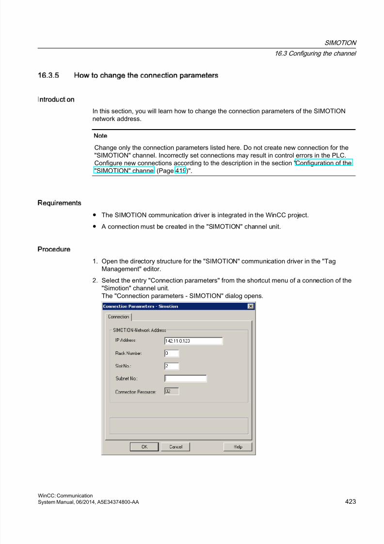
8/20/2019 WinCC Communication en-US en-US
http://slidepdf.com/reader/full/wincc-communication-en-us-en-us 423/527
16.3.5 How to change the connection parameters
Introduction
In this section, you will learn how to change the connection parameters of the SIMOTIONnetwork address.
Note
Change only the connection parameters listed here. Do not create new connection for the"SIMOTION" channel. Incorrectly set connections may result in control errors in the PLC.Configure new connections according to the description in the section "Configuration of the"SIMOTION" channel (Page 419)".
Requirements
● The SIMOTION communication driver is integrated in the WinCC project.
● A connection must be created in the "SIMOTION" channel unit.
Procedure
1. Open the directory structure for the "SIMOTION" communication driver in the "TagManagement" editor.
2. Select the entry "Connection parameters" from the shortcut menu of a connection of the
"Simotion" channel unit.The "Connection parameters - SIMOTION" dialog opens.
SIMOTION
16.3 Configuring the channel
WinCC: CommunicationSystem Manual, 06/2014, A5E34374800-AA 423

8/20/2019 WinCC Communication en-US en-US
http://slidepdf.com/reader/full/wincc-communication-en-us-en-us 424/527
3. Change the connection parameters for the SIMOTION network address in the respectivefields.
4. Close each open dialog box by clicking "OK."
16.3.6 How to change the tag address
Introduction
This section describes how to change a tag address in the "SIMOTION" channel.
Note
You must have very good knowledge of the use of ANY pointers to change the tag addressin the "SIMOTION" channel. No communication connection may be established if the tagaddress is entered incorrectly.
Requirements
● The "SIMOTION" channel in integrated into the WinCC project.
● A connection with tags has been created in the "SIMOTION" channel unit.
Procedure
1. Open the "SIMOTION tag address" dialog.For this purpose, click in the "Address" field and then on the button.
2. Change the tag address.
SIMOTION
16.3 Configuring the channel
WinCC: Communication424 System Manual, 06/2014, A5E34374800-AA
8/20/2019 WinCC Communication en-US en-US
http://slidepdf.com/reader/full/wincc-communication-en-us-en-us 425/527
16.3.7 System parameter configuration
16.3.7.1 System Parameters of the Channel Unit
Introduction
If you require a different configuration than the WinCC default settings, make these settingsin the "System Parameters" dialog box.
You can change the following system parameters:
● Logical device name
● The channel uses cyclic read services in the AS
Logical device name
WinCC and the PLC communicate by means of logical device names that are assigned whenthe communications processor is installed in the PLC.
The channel uses cyclic read services in the AS
The PLC cyclic read services group the tags that are to be read cyclically into individualrequests and transfer these to the PLC. The PLC sends the requested data the first time onreceipt of the request and then again each time the cycle time elapses.
When cyclic read services are enabled, you can use the change-driven transfer function. If thePLC supports change-driven transfer, the data are then transferred only when values arechanged.
16.3.7.2 How to Configure the System Parameters
Introduction
This section shows how to configure the system parameters of the "SIMOTION" channel.
The "System Parameters" dialog comprises two tabs:
● "SIMOTION" tab● "Unit" tab
Note
When the project is copied to another computer, the settings in the "Unit" tab are retained.The settings on the "SIMOTION" tab are deleted on the other hand.
SIMOTION
16.3 Configuring the channel
WinCC: CommunicationSystem Manual, 06/2014, A5E34374800-AA 425
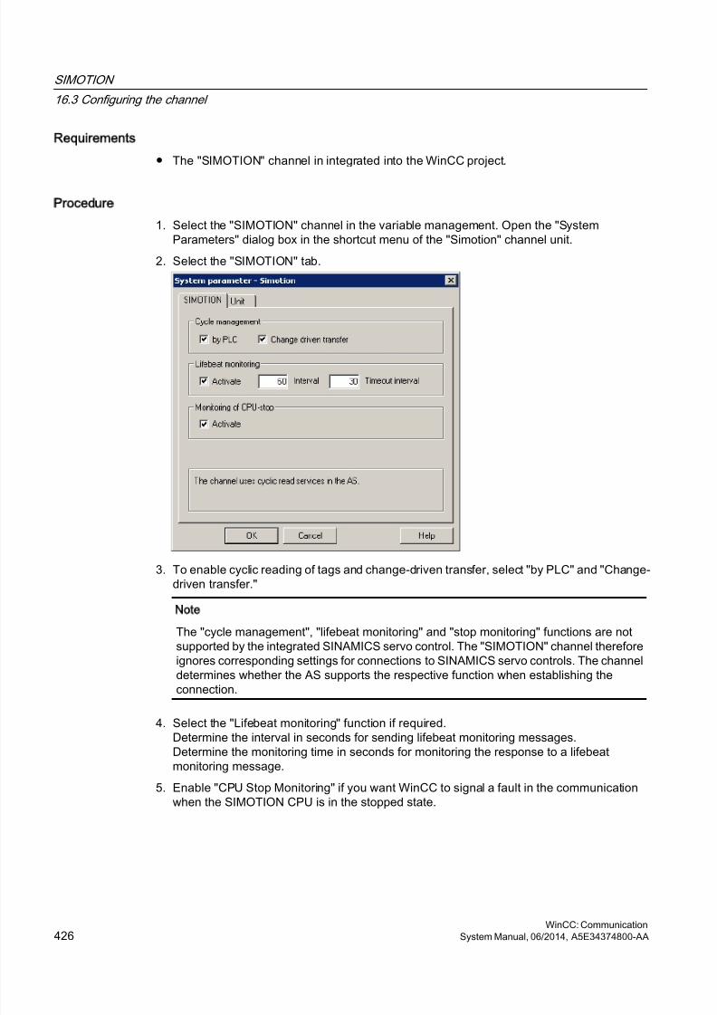
8/20/2019 WinCC Communication en-US en-US
http://slidepdf.com/reader/full/wincc-communication-en-us-en-us 426/527
Requirements
● The "SIMOTION" channel in integrated into the WinCC project.
Procedure
1. Select the "SIMOTION" channel in the variable management. Open the "SystemParameters" dialog box in the shortcut menu of the "Simotion" channel unit.
2. Select the "SIMOTION" tab.
3. To enable cyclic reading of tags and change-driven transfer, select "by PLC" and "Change-driven transfer."
Note
The "cycle management", "lifebeat monitoring" and "stop monitoring" functions are notsupported by the integrated SINAMICS servo control. The "SIMOTION" channel thereforeignores corresponding settings for connections to SINAMICS servo controls. The channeldetermines whether the AS supports the respective function when establishing theconnection.
4. Select the "Lifebeat monitoring" function if required.Determine the interval in seconds for sending lifebeat monitoring messages.Determine the monitoring time in seconds for monitoring the response to a lifebeatmonitoring message.
5. Enable "CPU Stop Monitoring" if you want WinCC to signal a fault in the communicationwhen the SIMOTION CPU is in the stopped state.
SIMOTION
16.3 Configuring the channel
WinCC: Communication426 System Manual, 06/2014, A5E34374800-AA
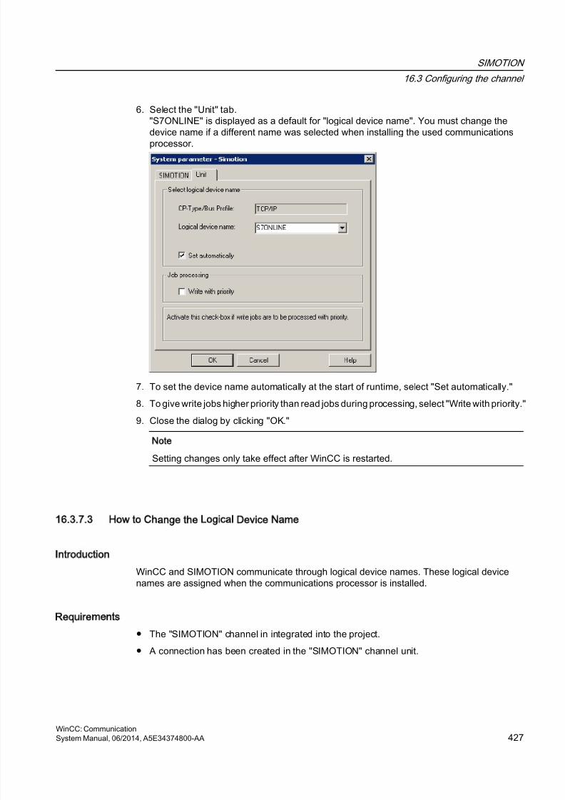
8/20/2019 WinCC Communication en-US en-US
http://slidepdf.com/reader/full/wincc-communication-en-us-en-us 427/527
6. Select the "Unit" tab."S7ONLINE" is displayed as a default for "logical device name". You must change thedevice name if a different name was selected when installing the used communications
processor.
7. To set the device name automatically at the start of runtime, select "Set automatically."
8. To give write jobs higher priority than read jobs during processing, select "Write with priority."
9. Close the dialog by clicking "OK."
Note
Setting changes only take effect after WinCC is restarted.
16.3.7.3 How to Change the Logical Device Name
Introduction
WinCC and SIMOTION communicate through logical device names. These logical devicenames are assigned when the communications processor is installed.
Requirements
● The "SIMOTION" channel in integrated into the project.
● A connection has been created in the "SIMOTION" channel unit.
SIMOTION
16.3 Configuring the channel
WinCC: CommunicationSystem Manual, 06/2014, A5E34374800-AA 427
8/20/2019 WinCC Communication en-US en-US
http://slidepdf.com/reader/full/wincc-communication-en-us-en-us 428/527
Procedure
1. Select the SIMOTION channel in Tag Management.
2. Open the "System Parameters" dialog box in the shortcut menu.
3. Select the "Unit" tab.
4. Enter the device name in the "Logical device name" field. You can select an entry from thelist or enter a new name.The device names are determined by the "Set PG/PC interface" tool. You call the tool inthe system control. Only the currently set device name is displayed if it is not installed.If you specify a different logical device name, a message is displayed.Only enter a name if the communications processor being used on the target station is notinstalled on the configuring system.
5. Close the dialog by clicking "OK."
Note
Setting changes only take effect after WinCC is restarted.
SIMOTION
16.3 Configuring the channel
WinCC: Communication428 System Manual, 06/2014, A5E34374800-AA
8/20/2019 WinCC Communication en-US en-US
http://slidepdf.com/reader/full/wincc-communication-en-us-en-us 429/527
16.4 Diagnosis SIMOTION channel
16.4.1 Diagnosis possibilities of the SIMOTION channel
The following possibilities exist for the diagnosis and error detection of the "SIMOTION"channel and its tags.
Checking the Communication Processor Configuration
After checking the access point, the communication processor can be tested with the "Set PG/PC interface" application. The communication processor can be checked under SIMATIC NETin the same way.
Checking the Configuration of the Connection and Tags
There may be errors in the configuration of the system and connection parameters. An incorrecttag addressing may also be responsible for wrong tag values.
Diagnosis of the Channel with Channel Diagnosis
You can query the status of the channel and the connection in runtime with "ChannelDiagnosis". Errors are displayed by "Error Codes".
Diagnosis of the Channel Tags
You can query the current value, the current quality code and the last change time of the tagin runtime in the tag management.
16.4.2 Description of Log File Entries
Introduction
The channel enters important status changes and errors in the logfile. The entries support the
analysis of communication faults.Every entry in the file contains a date and time stamp with the following flag names anddescription.
Example of a logbook entry:
2009-10-28 12:10:11,467 INFO Log starting ...
2009-10-28 12:10:11,483 INFO | LogFileName : D:\SIEMENS\WINCC\Diagnosis\Simotion_01.LOG
2009-10-28 12:10:11,483 INFO | LogFileCount : 3
SIMOTION
16.4 Diagnosis "SIMOTION" channel
WinCC: CommunicationSystem Manual, 06/2014, A5E34374800-AA 429
8/20/2019 WinCC Communication en-US en-US
http://slidepdf.com/reader/full/wincc-communication-en-us-en-us 430/527
2009-10-28 12:10:11,483 INFO | LogFileSize : 1400000
2009-10-28 12:10:11,483 INFO | TraceFlags : fa000000
2009-10-28 12:10:11,498 INFO SIMOTION channel DLL started!
2009-10-28 12:10:11,498 INFO SIMOTION channel with own cycle creation!
2009-10-28 12:10:11,967 INFO Connection "D445": StartRegisterEvVariable fordwVariableCount = 89
2009-10-28 12:10:11,967 INFO Connection "D445": RegisterEvVariable for Variable"@D445@CheckSum"!
...
2009-10-28 12:10:11,983 INFO Connection "D445": EndRegisterEvVariable
2009-10-28 12:10:12,436 INFO S7DOS release: @(#)TIS-Block Library DLL Version R8.0.0.0-
REL-BASIS2009-10-28 12:10:12,436 INFO S7DOS version: V8.0 / 0
2009-10-28 12:10:12,436 INFO SIMOTION version: V6.0 / Sep 15 2009 / 08:06:43
2009-10-28 12:10:12,436 INFO SIMOTION channel unit "Simotion" activated!
2009-10-28 12:10:12,451 ERROR Cannot connect to "SINAMICS_Integrated": Errorcode0xFFDF 42C2!
2009-10-28 12:10:12,451 ERROR Cannot connect to "D445": Errorcode 0xFFDF 42C2!
Description of the Most Important Entries for the INFO Flag
Message text Meaning
LogFileName : C:\ Siemens\ WinCC\Diagnose\ "channel_name".LOG
Name of the log file with path
LogFileCount : "n" Number of log files of the channel
LogFileSize : "x" Size of the individual log files in bytes
TraceFlags : c4000000 Displays the flags used by the Trace function as ahexadecimal number
SIMOTION channel DLL started! Start message
SIMOTION channel DLL terminated! End message
SIMOTION
16.4 Diagnosis "SIMOTION" channel
WinCC: Communication430 System Manual, 06/2014, A5E34374800-AA
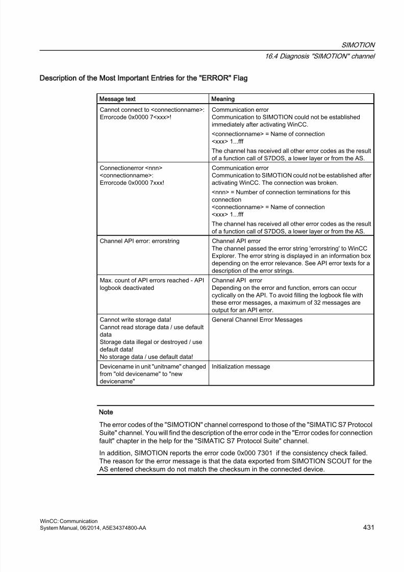
8/20/2019 WinCC Communication en-US en-US
http://slidepdf.com/reader/full/wincc-communication-en-us-en-us 431/527
Description of the Most Important Entries for the ERROR Flag
Message text Meaning
Cannot connect to <connectionname>:Errorcode 0x0000 7<xxx>!
Communication error Communication to SIMOTION could not be establishedimmediately after activating WinCC.
<connectionname> = Name of connection<xxx> 1...fff
The channel has received all other error codes as the resultof a function call of S7DOS, a lower layer or from the AS.
Connectionerror <nnn><connectionname>:Errorcode 0x0000 7xxx!
Communication error Communication to SIMOTION could not be established afteractivating WinCC. The connection was broken.
<nnn> = Number of connection terminations for this
connection<connectionname> = Name of connection<xxx> 1...fff
The channel has received all other error codes as the resultof a function call of S7DOS, a lower layer or from the AS.
Channel API error: errorstring Channel API error The channel passed the error string 'errorstring' to WinCCExplorer. The error string is displayed in an information boxdepending on the error relevance. See API error texts for adescription of the error strings.
Max. count of API errors reached - APIlogbook deactivated
Channel API error Depending on the error and function, errors can occurcyclically on the API. To avoid filling the logbook file with
these error messages, a maximum of 32 messages areoutput for an API error.
Cannot write storage data!Cannot read storage data / use defaultdataStorage data illegal or destroyed / usedefault data!No storage data / use default data!
General Channel Error Messages
Devicename in unit "unitname" changedfrom "old devicename" to "newdevicename"
Initialization message
Note
The error codes of the "SIMOTION" channel correspond to those of the "SIMATIC S7 ProtocolSuite" channel. You will find the description of the error code in the "Error codes for connectionfault" chapter in the help for the "SIMATIC S7 Protocol Suite" channel.
In addition, SIMOTION reports the error code 0x000 7301 if the consistency check failed.The reason for the error message is that the data exported from SIMOTION SCOUT for theAS entered checksum do not match the checksum in the connected device.
SIMOTION
16.4 Diagnosis "SIMOTION" channel
WinCC: CommunicationSystem Manual, 06/2014, A5E34374800-AA 431

8/20/2019 WinCC Communication en-US en-US
http://slidepdf.com/reader/full/wincc-communication-en-us-en-us 432/527
8/20/2019 WinCC Communication en-US en-US
http://slidepdf.com/reader/full/wincc-communication-en-us-en-us 433/527
System Info
17
17.1 System Info Channel
Contents
The "System Info" channel is used to evaluate system information such as the time, date, diskcapacity and provides functions such as timers and counters.
This chapter will show you
● configure the channel, connection and tags
● display system information in a process picture
● use system information to trigger and display a message
● display system information graphically
● display the system information from several servers in a multi-user system
WinCC: CommunicationSystem Manual, 06/2014, A5E34374800-AA 433
8/20/2019 WinCC Communication en-US en-US
http://slidepdf.com/reader/full/wincc-communication-en-us-en-us 434/527
17.2 WinCC System Info Channel
Principle
The System Info channel is used to evaluate system information such as the time, date, diskcapacity and provides functions such as timers and counters.
Possible applications are:
● Display of the time, date and day of the week in process pictures
● Triggering of events through evaluation of system information in scripts
● Display of the CPU load in a trend
● Display and monitoring of the available drive space on different servers of a client system
● Monitoring of the available disk capacity and triggering of a messageThe channel requires no hardware, since it directly accesses the system information of thecomputer on which it has been installed. In order for the channel to function, a connection mustbe set up. Additional connections are possible, but not required for the proper operation.
For more information regarding the diagnosis of channels and tags, refer to "CommunicationDiagnostics".
Note
Licensing
The process tags required for the System Info channel need no licenses. Thus, the tags arenot entered in the license count.
User Rights
If you have no administrator rights, you must be a member of the superusers of the "SystemMonitor User" group in order to use the System Info channel.
Communication Manual
The communication manual contains additional information and extensive examples for thechannel configuration. This manual is available for download on the Internet:
● http://support.automation.siemens.com/
Search by item number:
● A5E00391327
See also
Use in Multi-User and Client Systems (Page 456)
How To Call Up and Evaluate System Information (Page 443)
How to Configure the System Info Channel (Page 442)
Differences to Other Software Components (Page 441)
System Info
17.2 WinCC System Info Channel
WinCC: Communication434 System Manual, 06/2014, A5E34374800-AA

8/20/2019 WinCC Communication en-US en-US
http://slidepdf.com/reader/full/wincc-communication-en-us-en-us 435/527
Overview of the Supported System Information (Page 436)
Diagnosis of Channels and Tags (Page 463)
System Info
17.2 WinCC System Info Channel
WinCC: CommunicationSystem Manual, 06/2014, A5E34374800-AA 435
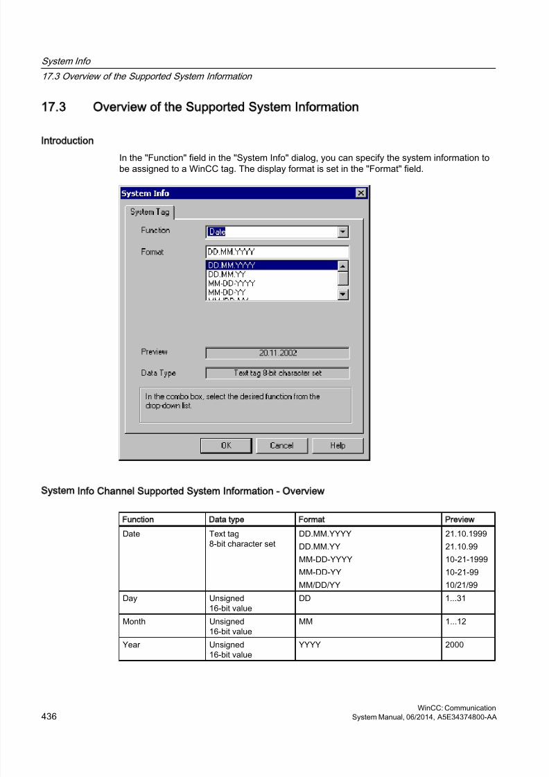
8/20/2019 WinCC Communication en-US en-US
http://slidepdf.com/reader/full/wincc-communication-en-us-en-us 436/527
17.3 Overview of the Supported System Information
Introduction
In the "Function" field in the "System Info" dialog, you can specify the system information tobe assigned to a WinCC tag. The display format is set in the "Format" field.
System Info Channel Supported System Information - Overview
Function Data type Format Preview
Date Text tag
8-bit character set
DD.MM.YYYY
DD.MM.YYMM-DD-YYYY
MM-DD-YY
MM/DD/YY
21.10.1999
21.10.9910-21-1999
10-21-99
10/21/99
Day Unsigned16-bit value
DD 1...31
Month Unsigned16-bit value
MM 1...12
Year Unsigned16-bit value
YYYY 2000
System Info
17.3 Overview of the Supported System Information
WinCC: Communication436 System Manual, 06/2014, A5E34374800-AA
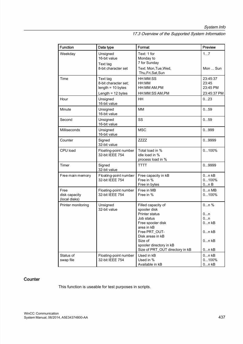
8/20/2019 WinCC Communication en-US en-US
http://slidepdf.com/reader/full/wincc-communication-en-us-en-us 437/527
Function Data type Format Preview
Weekday Unsigned
16-bit valueText tag8-bit character set
Text: 1 for
Monday to7 for Sunday
Text: Mon,Tue,Wed, Thu,Fri,Sat,Sun
1...7
Mon ... Sun
Time Text tag8-bit character set;length = 10 bytes
Length = 12 bytes
HH:MM:SSHH:MMHH:MM AM,PM
HH:MM:SS AM,PM
23:45:3723:4523:45 PM
23:45:37 PM
Hour Unsigned16-bit value
HH 0...23
Minute Unsigned16-bit value
MM 0...59
Second Unsigned16-bit value SS 0...59
Milliseconds Unsigned16-bit value
MSC 0...999
Counter Signed32-bit value
ZZZZ 0...9999
CPU load Floating-point number32-bit IEEE 754
Total load in %idle load in %process load in %
0...100%
Timer Signed32-bit value
TTTT 0...9999
Free main memory Floating-point number
32-bit IEEE 754
Free capacity in kB
Free in %Free in bytes
0...n kB
0...100%0...n B
Freedisk capacity(local disks)
Floating-point number32-bit IEEE 754
Free in MBFree in %
0...n MB0...100%
Printer monitoring Unsigned32-bit value
Filled capacity ofspooler diskPrinter statusJob statusFree spooler diskarea in kBFree PRT_OUT-Disk areas in kB
Size ofspooler directory in kBSize of PRT_OUT directory in kB
0...n %
0...n0...n0...n kB
0...n kB
0...n kB
0...n kB
Status ofswap file
Floating-point number32-bit IEEE 754
Used in kBUsed in %Available in kB
0...n kB0...100%0...n kB
Counter
This function is useable for test purposes in scripts.
System Info
17.3 Overview of the Supported System Information
WinCC: CommunicationSystem Manual, 06/2014, A5E34374800-AA 437
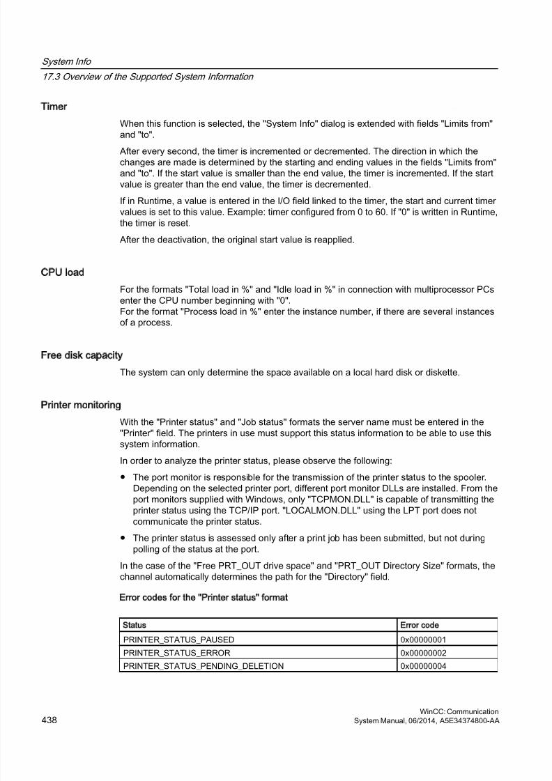
8/20/2019 WinCC Communication en-US en-US
http://slidepdf.com/reader/full/wincc-communication-en-us-en-us 438/527
Timer
When this function is selected, the "System Info" dialog is extended with fields "Limits from"
and "to".After every second, the timer is incremented or decremented. The direction in which thechanges are made is determined by the starting and ending values in the fields "Limits from"and "to". If the start value is smaller than the end value, the timer is incremented. If the startvalue is greater than the end value, the timer is decremented.
If in Runtime, a value is entered in the I/O field linked to the timer, the start and current timervalues is set to this value. Example: timer configured from 0 to 60. If "0" is written in Runtime,the timer is reset.
After the deactivation, the original start value is reapplied.
CPU load
For the formats "Total load in %" and "Idle load in %" in connection with multiprocessor PCsenter the CPU number beginning with "0".For the format "Process load in %" enter the instance number, if there are several instancesof a process.
Free disk capacity
The system can only determine the space available on a local hard disk or diskette.
Printer monitoring
With the "Printer status" and "Job status" formats the server name must be entered in the"Printer" field. The printers in use must support this status information to be able to use thissystem information.
In order to analyze the printer status, please observe the following:
● The port monitor is responsible for the transmission of the printer status to the spooler.Depending on the selected printer port, different port monitor DLLs are installed. From theport monitors supplied with Windows, only "TCPMON.DLL" is capable of transmitting theprinter status using the TCP/IP port. "LOCALMON.DLL" using the LPT port does notcommunicate the printer status.
● The printer status is assessed only after a print job has been submitted, but not during
polling of the status at the port.
In the case of the "Free PRT_OUT drive space" and "PRT_OUT Directory Size" formats, thechannel automatically determines the path for the "Directory" field.
Error codes for the Printer status format
Status Error code
PRINTER_STATUS_PAUSED 0x00000001
PRINTER_STATUS_ERROR 0x00000002
PRINTER_STATUS_PENDING_DELETION 0x00000004
System Info
17.3 Overview of the Supported System Information
WinCC: Communication438 System Manual, 06/2014, A5E34374800-AA
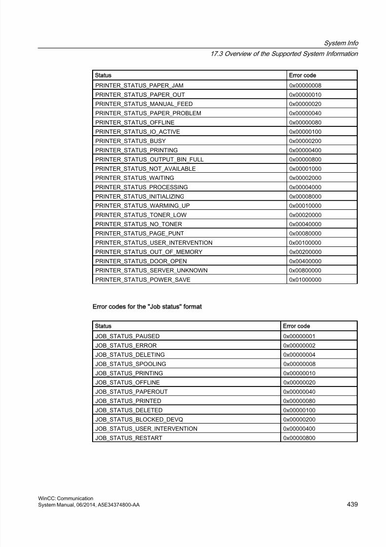
8/20/2019 WinCC Communication en-US en-US
http://slidepdf.com/reader/full/wincc-communication-en-us-en-us 439/527
Status Error code
PRINTER_STATUS_PAPER_JAM 0x00000008
PRINTER_STATUS_PAPER_OUT 0x00000010PRINTER_STATUS_MANUAL_FEED 0x00000020
PRINTER_STATUS_PAPER_PROBLEM 0x00000040
PRINTER_STATUS_OFFLINE 0x00000080
PRINTER_STATUS_IO_ACTIVE 0x00000100
PRINTER_STATUS_BUSY 0x00000200
PRINTER_STATUS_PRINTING 0x00000400
PRINTER_STATUS_OUTPUT_BIN_FULL 0x00000800
PRINTER_STATUS_NOT_AVAILABLE 0x00001000
PRINTER_STATUS_WAITING 0x00002000
PRINTER_STATUS_PROCESSING 0x00004000
PRINTER_STATUS_INITIALIZING 0x00008000
PRINTER_STATUS_WARMING_UP 0x00010000
PRINTER_STATUS_TONER_LOW 0x00020000
PRINTER_STATUS_NO_TONER 0x00040000
PRINTER_STATUS_PAGE_PUNT 0x00080000
PRINTER_STATUS_USER_INTERVENTION 0x00100000
PRINTER_STATUS_OUT_OF_MEMORY 0x00200000
PRINTER_STATUS_DOOR_OPEN 0x00400000
PRINTER_STATUS_SERVER_UNKNOWN 0x00800000
PRINTER_STATUS_POWER_SAVE 0x01000000
Error codes for the Job status format
Status Error code
JOB_STATUS_PAUSED 0x00000001
JOB_STATUS_ERROR 0x00000002
JOB_STATUS_DELETING 0x00000004
JOB_STATUS_SPOOLING 0x00000008
JOB_STATUS_PRINTING 0x00000010
JOB_STATUS_OFFLINE 0x00000020JOB_STATUS_PAPEROUT 0x00000040
JOB_STATUS_PRINTED 0x00000080
JOB_STATUS_DELETED 0x00000100
JOB_STATUS_BLOCKED_DEVQ 0x00000200
JOB_STATUS_USER_INTERVENTION 0x00000400
JOB_STATUS_RESTART 0x00000800
System Info
17.3 Overview of the Supported System Information
WinCC: CommunicationSystem Manual, 06/2014, A5E34374800-AA 439

8/20/2019 WinCC Communication en-US en-US
http://slidepdf.com/reader/full/wincc-communication-en-us-en-us 440/527
Note
The error codes of the "Printer status" and "Job status" formats corresponds to the values inthe Visual C-referenced file "Winspool.h" .
System Info
17.3 Overview of the Supported System Information
WinCC: Communication440 System Manual, 06/2014, A5E34374800-AA
8/20/2019 WinCC Communication en-US en-US
http://slidepdf.com/reader/full/wincc-communication-en-us-en-us 441/527
17.4 Differences to Other Software Components
Introduction
Some of the System Info channel system information can also be evaluated or displayed byWinCC using ActiveX controls.
Once fundamental difference to ActiveX controls can be seen in the fact that the System Infochannel system information is assigned to a WinCC tag. The continued evaluation (e.g. ofmessages, limit values) can be carried out repeatedly and is then configured individually. TheActiveX controls are intended for use in the specified applications and may also be used formulti-user or client systems.
For the following system information, differences between the ActiveX control and the channelexist:
Time
The ActiveX control "WinCC Digital/Analog Clock Control" is used to display the time in WinCC.This control also supports an analog display of the time. The control does not require theSystem Info channel even when if it is used in the process control system options. Using thecontrol, it is possible to display a WinCC client's time in its process picture. This is not possiblewith the System Info channel, since this always displays the server's system time.
Free disk capacity
The ActiveX control "IX Diskspace" is supplied to display the disk space available in WinCC.
This ActiveX control can also display the space available on network drives and supports otherconfiguration options such as the setting of multiple limit values directly in the control.
System Info
17.4 Differences to Other Software Components
WinCC: CommunicationSystem Manual, 06/2014, A5E34374800-AA 441
8/20/2019 WinCC Communication en-US en-US
http://slidepdf.com/reader/full/wincc-communication-en-us-en-us 442/527
17.5 Configuring the Channel
17.5.1 How to Configure the System Info Channel
Introduction
This section illustrates how to configure the System Info channel.
Procedure
1. In the navigation area of the tag management, select the entry "Add new driver" in theshortcut menu of node "Tag Management".
2. Select the "System Info" driver. The channel is created and the communication driver isdisplayed in the tag management.
3. Select the associated System Info channel unit and call up the shortcut menu. In thisshortcut menu, select "New Connection".
4. Enter the name of the connection.
5. Click the "Tags" tab below the table area.
6. Click in the top free cell of the "Name" column.Enter the name for the tag.If you want to use examples for this channel, continue with the topic "How to Configure aTag".
7. Select the desired data type in the "Data Type" field.
System Info
17.5 Configuring the Channel
WinCC: Communication442 System Manual, 06/2014, A5E34374800-AA
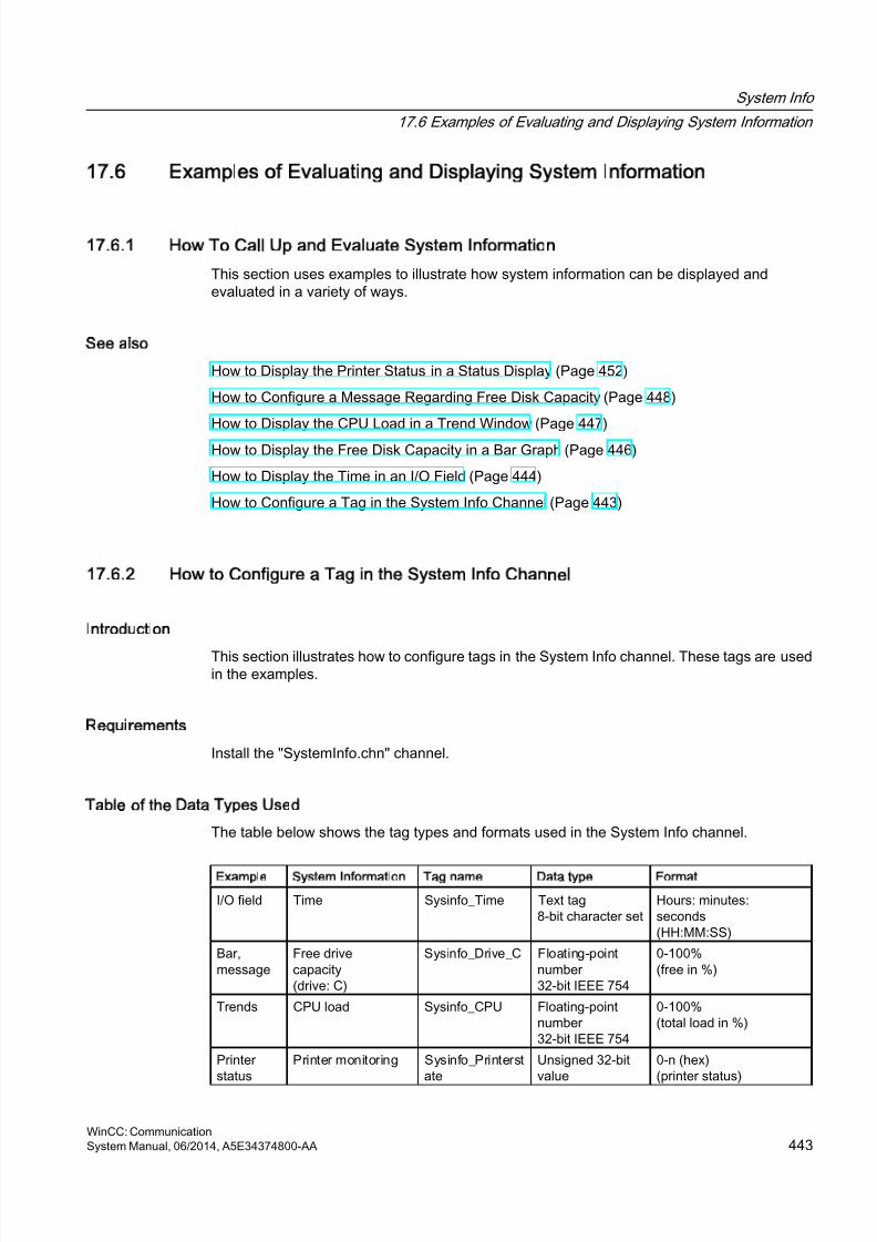
8/20/2019 WinCC Communication en-US en-US
http://slidepdf.com/reader/full/wincc-communication-en-us-en-us 443/527
17.6 Examples of Evaluating and Displaying System Information
17.6.1 How To Call Up and Evaluate System Information
This section uses examples to illustrate how system information can be displayed andevaluated in a variety of ways.
See also
How to Display the Printer Status in a Status Display (Page 452)
How to Configure a Message Regarding Free Disk Capacity (Page 448)
How to Display the CPU Load in a Trend Window (Page 447)
How to Display the Free Disk Capacity in a Bar Graph (Page 446)
How to Display the Time in an I/O Field (Page 444)
How to Configure a Tag in the System Info Channel (Page 443)
17.6.2 How to Configure a Tag in the System Info Channel
Introduction
This section illustrates how to configure tags in the System Info channel. These tags are usedin the examples.
Requirements
Install the "SystemInfo.chn" channel.
Table of the Data Types Used
The table below shows the tag types and formats used in the System Info channel.
Example System Information Tag name Data type Format
I/O field Time Sysinfo_Time Text tag8-bit character set
Hours: minutes:seconds(HH:MM:SS)
Bar,message
Free drivecapacity(drive: C)
Sysinfo_Drive_C Floating-pointnumber32-bit IEEE 754
0-100%(free in %)
Trends CPU load Sysinfo_CPU Floating-pointnumber 32-bit IEEE 754
0-100%(total load in %)
Printerstatus
Printer monitoring Sysinfo_Printerstate
Unsigned 32-bitvalue
0-n (hex)(printer status)
System Info
17.6 Examples of Evaluating and Displaying System Information
WinCC: CommunicationSystem Manual, 06/2014, A5E34374800-AA 443
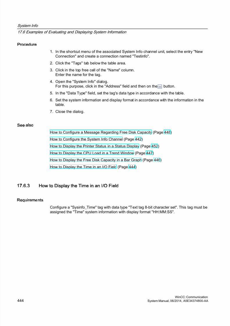
8/20/2019 WinCC Communication en-US en-US
http://slidepdf.com/reader/full/wincc-communication-en-us-en-us 444/527
Procedure
1. In the shortcut menu of the associated System Info channel unit, select the entry "New
Connection" and create a connection named "Testinfo".2. Click the "Tags" tab below the table area.
3. Click in the top free cell of the "Name" column.Enter the name for the tag.
4. Open the "System Info" dialog.For this purpose, click in the "Address" field and then on the button.
5. In the "Data Type" field, set the tag's data type in accordance with the table.
6. Set the system information and display format in accordance with the information in thetable.
7. Close the dialog.
See also
How to Configure a Message Regarding Free Disk Capacity (Page 448)
How to Configure the System Info Channel (Page 442)
How to Display the Printer Status in a Status Display (Page 452)
How to Display the CPU Load in a Trend Window (Page 447)
How to Display the Free Disk Capacity in a Bar Graph (Page 446)
How to Display the Time in an I/O Field (Page 444)
17.6.3 How to Display the Time in an I/O Field
Requirements
Configure a "Sysinfo_Time" tag with data type "Text tag 8-bit character set". This tag must beassigned the "Time" system information with display format "HH:MM:SS".
System Info
17.6 Examples of Evaluating and Displaying System Information
WinCC: Communication444 System Manual, 06/2014, A5E34374800-AA

8/20/2019 WinCC Communication en-US en-US
http://slidepdf.com/reader/full/wincc-communication-en-us-en-us 445/527
Procedure
1. Start Graphics Designer and open a picture.
2. Add an I/O field to the picture. Select the "I/O field" object from the object list under "SmartObjects". The "I/O Field Configuration" dialog is opened.
3. In the "Tag" field, enter the name "Sysinfo_Time".
4. Set the update to "1 s".
5. Set the field type to "Output". Close the dialog.
6. Click "Properties" in the I/O field's shortcut menu to open the "Object Properties" dialog.
7. On the "Properties" tab, select "Output/Input". Set the "Data Format" attribute to "String".
8. Close the dialog and save the picture.
9. Click the appropriate button in the Graphics Designer toolbar to activate Runtime.
Note
The update cycle should be chosen with careful consideration, as it affects the load on thecomputer. Therefore, updating a time display every 250 ms is detrimental to the systemperformance.
See also
How to Start Runtime (Page 455)How to Insert an I/O Field (Page 455)
How to Configure a Tag in the System Info Channel (Page 443)
System Info
17.6 Examples of Evaluating and Displaying System Information
WinCC: CommunicationSystem Manual, 06/2014, A5E34374800-AA 445
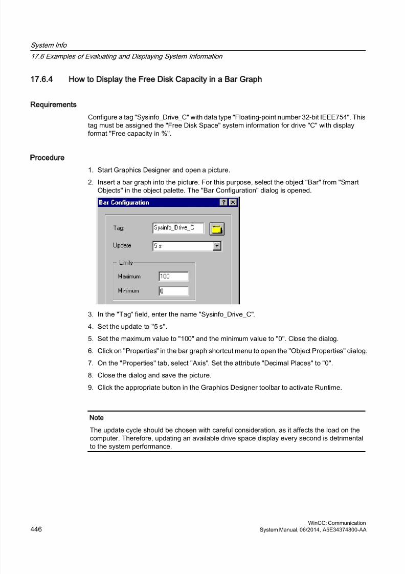
8/20/2019 WinCC Communication en-US en-US
http://slidepdf.com/reader/full/wincc-communication-en-us-en-us 446/527
17.6.4 How to Display the Free Disk Capacity in a Bar Graph
Requirements
Configure a tag "Sysinfo_Drive_C" with data type "Floating-point number 32-bit IEEE754". Thistag must be assigned the "Free Disk Space" system information for drive "C" with displayformat "Free capacity in %".
Procedure
1. Start Graphics Designer and open a picture.
2. Insert a bar graph into the picture. For this purpose, select the object "Bar" from "SmartObjects" in the object palette. The "Bar Configuration" dialog is opened.
3. In the "Tag" field, enter the name "Sysinfo_Drive_C".
4. Set the update to "5 s".
5. Set the maximum value to "100" and the minimum value to "0". Close the dialog.
6. Click on "Properties" in the bar graph shortcut menu to open the "Object Properties" dialog.
7. On the "Properties" tab, select "Axis". Set the attribute "Decimal Places" to "0".
8. Close the dialog and save the picture.
9. Click the appropriate button in the Graphics Designer toolbar to activate Runtime.
Note
The update cycle should be chosen with careful consideration, as it affects the load on thecomputer. Therefore, updating an available drive space display every second is detrimentalto the system performance.
System Info
17.6 Examples of Evaluating and Displaying System Information
WinCC: Communication446 System Manual, 06/2014, A5E34374800-AA
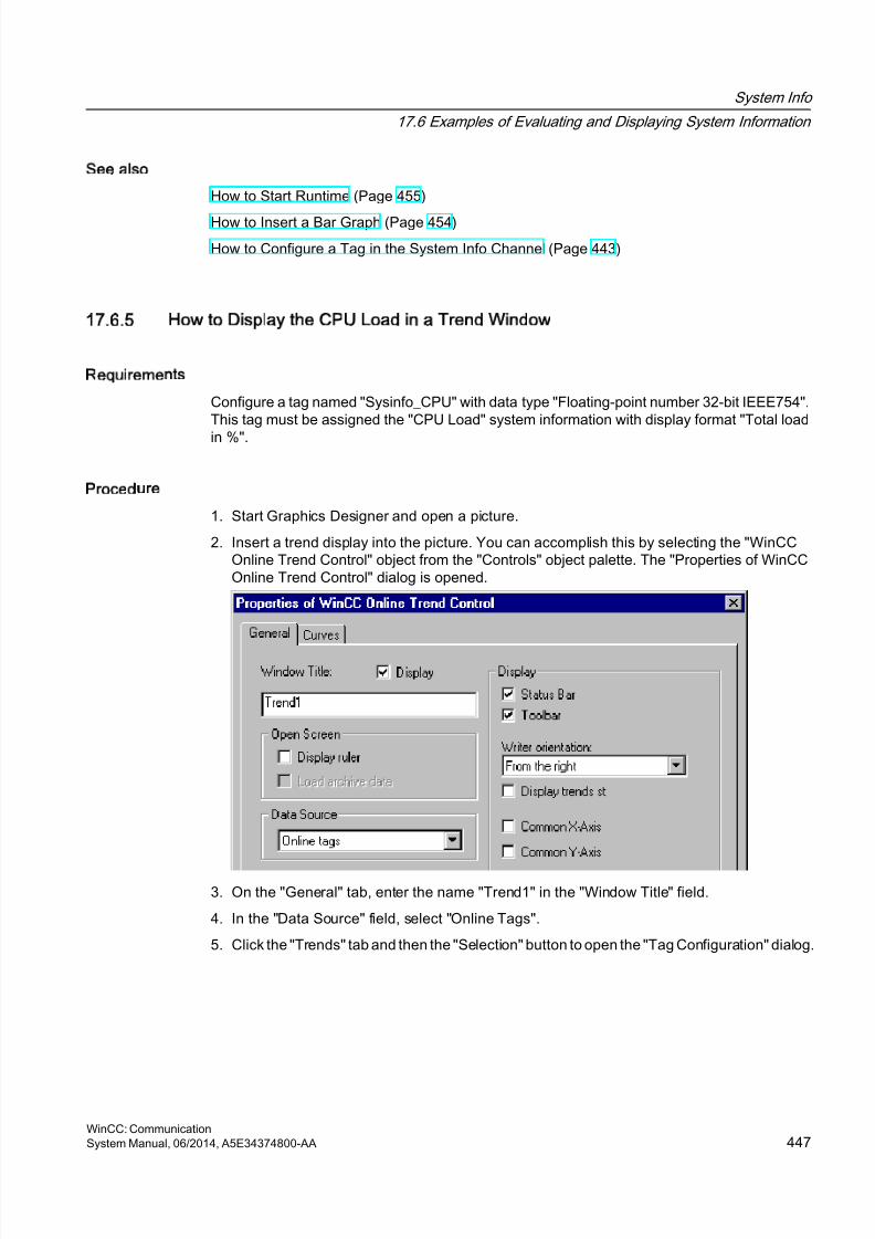
8/20/2019 WinCC Communication en-US en-US
http://slidepdf.com/reader/full/wincc-communication-en-us-en-us 447/527
See also
How to Start Runtime (Page 455)
How to Insert a Bar Graph (Page 454)
How to Configure a Tag in the System Info Channel (Page 443)
17.6.5 How to Display the CPU Load in a Trend Window
Requirements
Configure a tag named "Sysinfo_CPU" with data type "Floating-point number 32-bit IEEE754".This tag must be assigned the "CPU Load" system information with display format "Total load
in %".
Procedure
1. Start Graphics Designer and open a picture.
2. Insert a trend display into the picture. You can accomplish this by selecting the "WinCCOnline Trend Control" object from the "Controls" object palette. The "Properties of WinCCOnline Trend Control" dialog is opened.
3. On the "General" tab, enter the name "Trend1" in the "Window Title" field.
4. In the "Data Source" field, select "Online Tags".
5. Click the "Trends" tab and then the "Selection" button to open the "Tag Configuration" dialog.
System Info
17.6 Examples of Evaluating and Displaying System Information
WinCC: CommunicationSystem Manual, 06/2014, A5E34374800-AA 447

8/20/2019 WinCC Communication en-US en-US
http://slidepdf.com/reader/full/wincc-communication-en-us-en-us 448/527
6. Enter "Sysinfo_CPU" as the name of the tag and then select a cycle time of "2 s". Closethe dialog.
7. Close the "Properties of WinCC Online Trend Control" dialog and save the picture.
8. Click the appropriate button in the Graphics Designer toolbar to activate Runtime.
Note
The update cycle should be chosen with careful consideration, as it affects the load on thecomputer. Therefore, updating a CPU load display every 500 ms is detrimental to the systemperformance.
See also
How to Start Runtime (Page 455)
How to Configure a Tag in the System Info Channel (Page 443)
17.6.6 How to Configure a Message Regarding Free Disk Capacity
Requirements
Configure a tag "Sysinfo_Drive_C" with data type "Floating-point number 32-bit IEEE754". Thistag must be assigned the "Free Disk Space" system information for drive "C" with displayformat "Free capacity in %".
System Info
17.6 Examples of Evaluating and Displaying System Information
WinCC: Communication448 System Manual, 06/2014, A5E34374800-AA
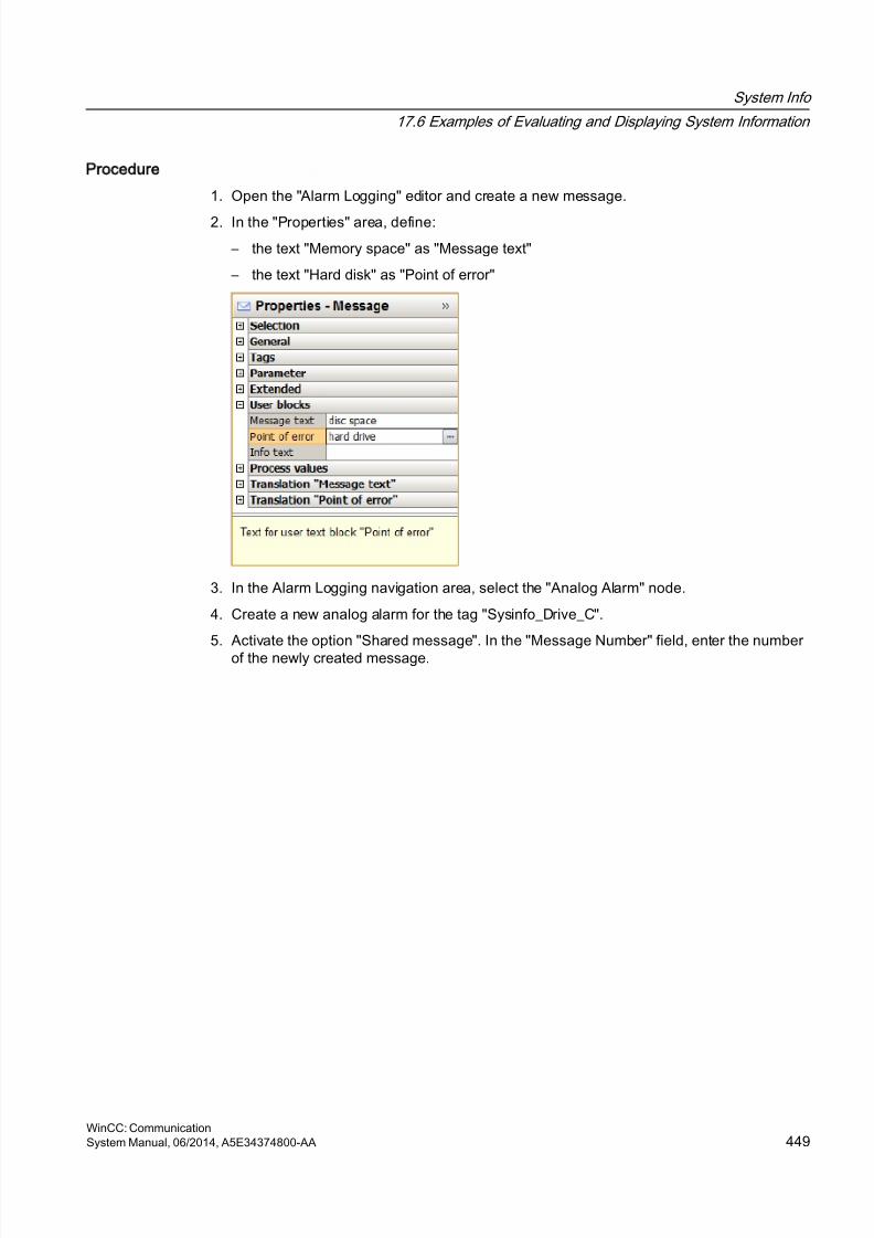
8/20/2019 WinCC Communication en-US en-US
http://slidepdf.com/reader/full/wincc-communication-en-us-en-us 449/527
Procedure
1. Open the "Alarm Logging" editor and create a new message.
2. In the "Properties" area, define:
– the text "Memory space" as "Message text"
– the text "Hard disk" as "Point of error"
3. In the Alarm Logging navigation area, select the "Analog Alarm" node.
4. Create a new analog alarm for the tag "Sysinfo_Drive_C".
5. Activate the option "Shared message". In the "Message Number" field, enter the numberof the newly created message.
System Info
17.6 Examples of Evaluating and Displaying System Information
WinCC: CommunicationSystem Manual, 06/2014, A5E34374800-AA 449
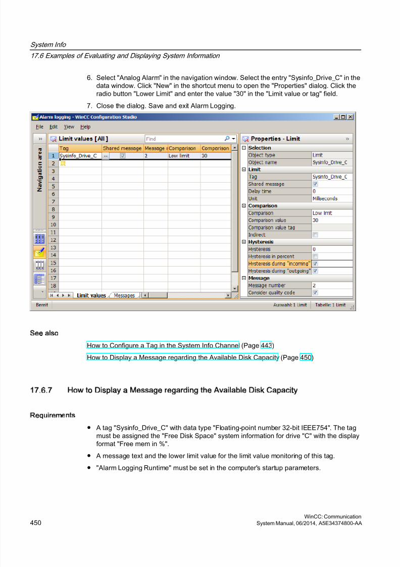
8/20/2019 WinCC Communication en-US en-US
http://slidepdf.com/reader/full/wincc-communication-en-us-en-us 450/527
6. Select "Analog Alarm" in the navigation window. Select the entry "Sysinfo_Drive_C" in thedata window. Click "New" in the shortcut menu to open the "Properties" dialog. Click theradio button "Lower Limit" and enter the value "30" in the "Limit value or tag" field.
7. Close the dialog. Save and exit Alarm Logging.
See also
How to Configure a Tag in the System Info Channel (Page 443)
How to Display a Message regarding the Available Disk Capacity (Page 450)
17.6.7 How to Display a Message regarding the Available Disk Capacity
Requirements
● A tag "Sysinfo_Drive_C" with data type "Floating-point number 32-bit IEEE754". The tagmust be assigned the "Free Disk Space" system information for drive "C" with the displayformat "Free mem in %".
● A message text and the lower limit value for the limit value monitoring of this tag.
● "Alarm Logging Runtime" must be set in the computer's startup parameters.
System Info
17.6 Examples of Evaluating and Displaying System Information
WinCC: Communication450 System Manual, 06/2014, A5E34374800-AA
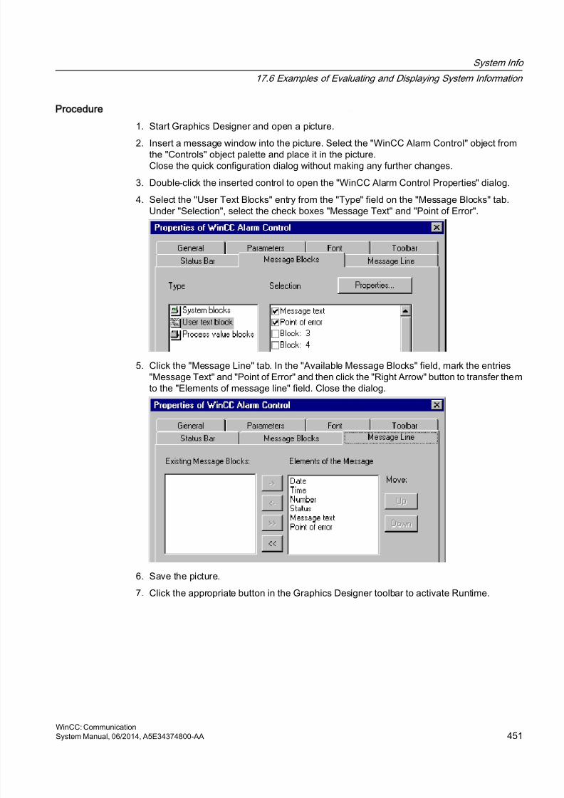
8/20/2019 WinCC Communication en-US en-US
http://slidepdf.com/reader/full/wincc-communication-en-us-en-us 451/527
Procedure
1. Start Graphics Designer and open a picture.
2. Insert a message window into the picture. Select the "WinCC Alarm Control" object fromthe "Controls" object palette and place it in the picture.Close the quick configuration dialog without making any further changes.
3. Double-click the inserted control to open the "WinCC Alarm Control Properties" dialog.
4. Select the "User Text Blocks" entry from the "Type" field on the "Message Blocks" tab.Under "Selection", select the check boxes "Message Text" and "Point of Error".
5. Click the "Message Line" tab. In the "Available Message Blocks" field, mark the entries"Message Text" and "Point of Error" and then click the "Right Arrow" button to transfer themto the "Elements of message line" field. Close the dialog.
6. Save the picture.
7. Click the appropriate button in the Graphics Designer toolbar to activate Runtime.
System Info
17.6 Examples of Evaluating and Displaying System Information
WinCC: CommunicationSystem Manual, 06/2014, A5E34374800-AA 451
8/20/2019 WinCC Communication en-US en-US
http://slidepdf.com/reader/full/wincc-communication-en-us-en-us 452/527
See also
How to Check the WinCC Startup Parameters (Page 454)
How to Start Runtime (Page 455)
How to Configure a Tag in the System Info Channel (Page 443)
17.6.8 How to Display the Printer Status in a Status Display
Introduction
This example shows a possible evaluation of the "Printer monitoring" system information basedon the "Printer status" display format. The printer or job status could also be evaluated by
configuring messages that are triggered by single bits in the printer or job status.
Requirements
● Configure a "Sysinfo_Printerstate" tag with data type "Unsigned 32-bit value". This tag mustbe assigned to the "Printer monitoring" system information with the "Printer status" displayformat.
● The printers in use must support these status displays to be able to use this systeminformation.
System Info
17.6 Examples of Evaluating and Displaying System Information
WinCC: Communication452 System Manual, 06/2014, A5E34374800-AA
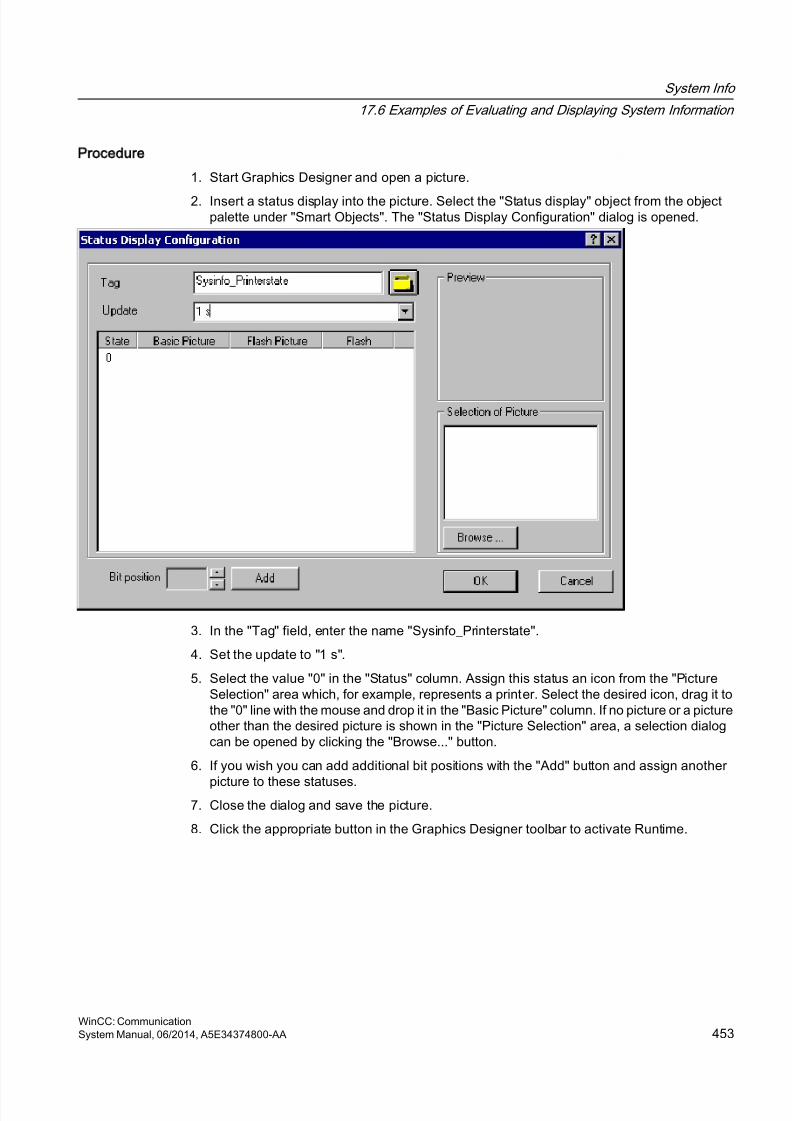
8/20/2019 WinCC Communication en-US en-US
http://slidepdf.com/reader/full/wincc-communication-en-us-en-us 453/527
Procedure
1. Start Graphics Designer and open a picture.
2. Insert a status display into the picture. Select the "Status display" object from the objectpalette under "Smart Objects". The "Status Display Configuration" dialog is opened.
3. In the "Tag" field, enter the name "Sysinfo_Printerstate".
4. Set the update to "1 s".
5. Select the value "0" in the "Status" column. Assign this status an icon from the "PictureSelection" area which, for example, represents a printer. Select the desired icon, drag it tothe "0" line with the mouse and drop it in the "Basic Picture" column. If no picture or a pictureother than the desired picture is shown in the "Picture Selection" area, a selection dialogcan be opened by clicking the "Browse..." button.
6. If you wish you can add additional bit positions with the "Add" button and assign another
picture to these statuses.7. Close the dialog and save the picture.
8. Click the appropriate button in the Graphics Designer toolbar to activate Runtime.
System Info
17.6 Examples of Evaluating and Displaying System Information
WinCC: CommunicationSystem Manual, 06/2014, A5E34374800-AA 453
8/20/2019 WinCC Communication en-US en-US
http://slidepdf.com/reader/full/wincc-communication-en-us-en-us 454/527
In Runtime, a printer ready for use is displayed with the icon assigned the status "0" in step 5.No picture is shown if there is an error in the printer or if you have not run step 6. If you assignedicons to the other bit positions in step 6, they are shown accordingly.
Note
The update cycle should be chosen with careful consideration, as it affects the load on thecomputer. Therefore, updating a time display every 250 ms is detrimental to the systemperformance.
See also
How to Configure a Tag in the System Info Channel (Page 443)
How to Start Runtime (Page 455)
17.6.9 How to Check the WinCC Startup Parameters
Procedure
1. In WinCC Explorer, select "Computer".
2. Open the shortcut menu and select "Properties".
3. The "Computer List Properties" dialog is opened. Click the "Properties" button.
4. The "Computer Properties" dialog is opened.
5. Click the "Startup" tab and check the entries. If necessary, activate or deactivate Runtimemodules or add other applications to the startup list.
6. Close the open dialogs.
17.6.10 How to Insert a Bar Graph
Procedure
1. Start Graphics Designer and open a picture.
2. In the "Standard" object palette under "Smart Objects", select the object "Bar".
3. Insert a bar graph into the picture. To do this, point the mouse on the location in the workingarea where you want the bar graph to be placed. While keeping the mouse button pressed,drag the object to the desired size.
4. After you release the mouse button, the "Bar Configuration" dialog is opened. In this dialog,enter the name of a WinCC tag and set the update specifications and limit. Additionally,you can use the "Bar Direction" to set the orientation of the displayed bar.
5. Close the dialog.
System Info
17.6 Examples of Evaluating and Displaying System Information
WinCC: Communication454 System Manual, 06/2014, A5E34374800-AA
8/20/2019 WinCC Communication en-US en-US
http://slidepdf.com/reader/full/wincc-communication-en-us-en-us 455/527
17.6.11 How to Insert an I/O Field
Procedure
1. Start Graphics Designer and open a picture.
2. In the "Standard" object palette under "Smart Objects", select the object "I/O Field".
3. Insert the I/O field into the picture. To do this, position the mouse on the location in theworking area where you want the I/O field to be placed. While keeping the mouse buttonpressed, drag the object to the desired size.
4. After you release the mouse button, the "I/O Field Configuration" dialog is opened. In thisdialog, enter the name of a WinCC tag and set the update and field type settings.Additionally, you can also select the "Font" to be used to display the value.
5. Close the dialog.
17.6.12 How to Start Runtime
Requirements
A startup picture must be defined before Runtime is activated.
Procedure
1. Save and close all files that may be open in an editor.
2. Select WinCC Explorer.
3. Activate the project by clicking the "Activate" button in the toolbar or by selecting "Activate"in the "File" menu.
System Info
17.6 Examples of Evaluating and Displaying System Information
WinCC: CommunicationSystem Manual, 06/2014, A5E34374800-AA 455
8/20/2019 WinCC Communication en-US en-US
http://slidepdf.com/reader/full/wincc-communication-en-us-en-us 456/527
17.7 Special Functions
17.7.1 Use in Multi-User and Client Systems
17.7.1.1 Use in Multi-User and Client Systems
Introduction
In multi-user and client systems, the System Info channel can be used to process the systeminformation from a server on a client system. In a client system, it is thus possible for a singleWinCC client to monitor several servers.
See also
Monitoring the system information of several servers on a WinCC client (Page 456)
17.7.2 Example of monitoring system information from multiple servers
17.7.2.1 Monitoring the system information of several servers on a WinCC client
Introduction
In this example, two servers are monitored by a single WinCC client. The monitored systeminformation such as available disk space and CPU load is displayed in a process picture onthe WinCC client.
This requires the following configurations:
Configuration of first server
Configuration of second server
Import of tags on the WinCC client
Configuration of the process picture on the WinCC client
Activation of the project
Requirements
The server and the WinCC client must be connected through a Windows network.
System Info
17.7 Special Functions
WinCC: Communication456 System Manual, 06/2014, A5E34374800-AA
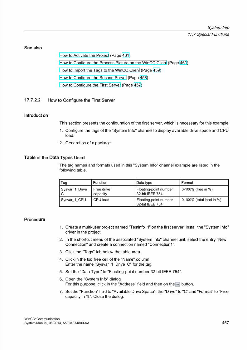
8/20/2019 WinCC Communication en-US en-US
http://slidepdf.com/reader/full/wincc-communication-en-us-en-us 457/527
See also
How to Activate the Project (Page 461)
How to Configure the Process Picture on the WinCC Client (Page 460)
How to Import the Tags to the WinCC Client (Page 459)
How to Configure the Second Server (Page 458)
How to Configure the First Server (Page 457)
17.7.2.2 How to Configure the First Server
Introduction
This section presents the configuration of the first server, which is necessary for this example.1. Configure the tags of the "System Info" channel to display available drive space and CPU
load.
2. Generation of a package.
Table of the Data Types Used
The tag names and formats used in this "System Info" channel example are listed in thefollowing table.
Tag Function Data type Format
Sysvar_1_Drive_ C
Free drivecapacity
Floating-point number 32-bit IEEE 754
0-100% (free in %)
Sysvar_1_CPU CPU load Floating-point number 32-bit IEEE 754
0-100% (total load in %)
Procedure
1. Create a multi-user project named "Testinfo_1" on the first server. Install the "System Info"driver in the project.
2. In the shortcut menu of the associated "System Info" channel unit, select the entry "New
Connection" and create a connection named "Connection1".3. Click the "Tags" tab below the table area.
4. Click in the top free cell of the "Name" column.Enter the name "Sysvar_1_Drive_C" for the tag.
5. Set the "Data Type" to "Floating-point number 32-bit IEEE 754".
6. Open the "System Info" dialog.For this purpose, click in the "Address" field and then on the button.
7. Set the "Function" field to "Available Drive Space", the "Drive" to "C" and "Format" to "Freecapacity in %". Close the dialog.
System Info
17.7 Special Functions
WinCC: CommunicationSystem Manual, 06/2014, A5E34374800-AA 457

8/20/2019 WinCC Communication en-US en-US
http://slidepdf.com/reader/full/wincc-communication-en-us-en-us 458/527
8. Click in the top free cell of the "Name" column.Enter the name "Sysvar_1_CPU" for the tag.
9. Set the "Data Type" to "Floating-point number 32-bit IEEE 754".10.Open the dialog "System Info".
For this purpose, click in the "Address" field and then on the button.
11.Set the value in the "Function" field to "CPU Load" and the value in "Format" to "Total loadin %". Close the dialog.
12.Create a package. Proceed by selecting "Server data" in the navigation window andopening the shortcut menu. Select the menu item "Create". Acknowledge the messagestating that the package was created.
See also
How to Configure the Second Server (Page 458)
17.7.2.3 How to Configure the Second Server
Introduction
This section presents the configuration of the second server, which is necessary for thisexample.
1. Configure the tags of the "System Info" channel to display available drive space and CPUload.
2. Generation of a package.
Table of the Data Types Used
The tag names and formats used in this "System Info" channel example are listed in thefollowing table.
Tag Function Data type Format
Sysvar_2_Drive_ C
Free drivecapacity
Floating-point number32-bit IEEE 754
0-100% (free in %)
Sysvar_2_CPU CPU load Floating-point number32-bit IEEE 754 0-100% (total load in %)
Procedure
1. Create a multi-user project named "Testinfo_2" on the second server. Install the "SystemInfo" driver in the project.
2. In the shortcut menu for the associated "System Info" channel unit, select the entry "NewConnection" and create a connection named "Connection2".
3. Click the "Tags" tab below the table area.
System Info
17.7 Special Functions
WinCC: Communication458 System Manual, 06/2014, A5E34374800-AA
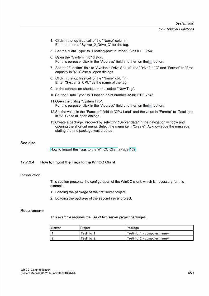
8/20/2019 WinCC Communication en-US en-US
http://slidepdf.com/reader/full/wincc-communication-en-us-en-us 459/527
4. Click in the top free cell of the "Name" column.Enter the name "Sysvar_2_Drive_C" for the tag.
5. Set the "Data Type" to "Floating-point number 32-bit IEEE 754".6. Open the "System Info" dialog.
For this purpose, click in the "Address" field and then on the button.
7. Set the "Function" field to "Available Drive Space", the "Drive" to "C" and "Format" to "Freecapacity in %". Close all open dialogs.
8. Click in the top free cell of the "Name" column.Enter "Sysvar_2_CPU" as the name of the tag.
9. In the connection shortcut menu, select "New Tag".
10.Set the "Data Type" to "Floating-point number 32-bit IEEE 754".
11.Open the dialog "System Info".For this purpose, click in the "Address" field and then on the button.
12.Set the value in the "Function" field to "CPU Load" and the value in "Format" to "Total loadin %". Close all open dialogs.
13.Create a package. Proceed by selecting "Server data" in the navigation window andopening the shortcut menu. Select the menu item "Create". Acknowledge the messagestating that the package was created.
See also
How to Import the Tags to the WinCC Client (Page 459)
17.7.2.4 How to Import the Tags to the WinCC Client
Introduction
This section presents the configuration of the WinCC client, which is necessary for thisexample.
1. Loading the package of the first sever project.
2. Loading the package of the second sever project.
Requirements
This example requires the use of two server project packages.
Server Project Package
1 Testinfo_1 Testinfo_1_<computer_name>
2 Testinfo_2 Testinfo_2_<computer_name>
System Info
17.7 Special Functions
WinCC: CommunicationSystem Manual, 06/2014, A5E34374800-AA 459
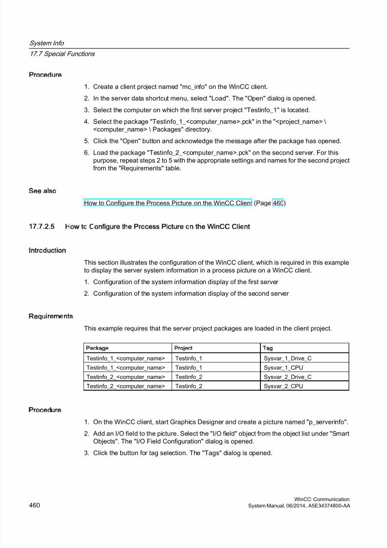
8/20/2019 WinCC Communication en-US en-US
http://slidepdf.com/reader/full/wincc-communication-en-us-en-us 460/527
Procedure
1. Create a client project named "mc_info" on the WinCC client.
2. In the server data shortcut menu, select "Load". The "Open" dialog is opened.
3. Select the computer on which the first server project "Testinfo_1" is located.
4. Select the package "Testinfo_1_<computer_name>.pck" in the "<project_name> \<computer_name> \ Packages" directory.
5. Click the "Open" button and acknowledge the message after the package has opened.
6. Load the package "Testinfo_2_<computer_name>.pck" on the second server. For thispurpose, repeat steps 2 to 5 with the appropriate settings and names for the second projectfrom the "Requirements" table.
See also
How to Configure the Process Picture on the WinCC Client (Page 460)
17.7.2.5 How to Configure the Process Picture on the WinCC Client
Introduction
This section illustrates the configuration of the WinCC client, which is required in this exampleto display the server system information in a process picture on a WinCC client.
1. Configuration of the system information display of the first server
2. Configuration of the system information display of the second server
Requirements
This example requires that the server project packages are loaded in the client project.
Package Project Tag
Testinfo_1_<computer_name> Testinfo_1 Sysvar_1_Drive_C
Testinfo_1_<computer_name> Testinfo_1 Sysvar_1_CPU
Testinfo_2_<computer_name> Testinfo_2 Sysvar_2_Drive_C
Testinfo_2_<computer_name> Testinfo_2 Sysvar_2_CPU
Procedure
1. On the WinCC client, start Graphics Designer and create a picture named "p_serverinfo".
2. Add an I/O field to the picture. Select the "I/O field" object from the object list under "SmartObjects". The "I/O Field Configuration" dialog is opened.
3. Click the button for tag selection. The "Tags" dialog is opened.
System Info
17.7 Special Functions
WinCC: Communication460 System Manual, 06/2014, A5E34374800-AA
8/20/2019 WinCC Communication en-US en-US
http://slidepdf.com/reader/full/wincc-communication-en-us-en-us 461/527
4. Select the tag "Sysvar_1_Drive_C" of the first server project "Testinfo_1". For this purpose,open the directory structure under the package "Testinfo_1_<computer_name>". Close thedialog.
5. In the "I/O Field Configuration" dialog, set the update to "5 s".
6. Set the field type to "Output". Close the dialog.
7. Insert a second I/O field into the picture and configure it for the tag "Sysvar_1_CPU" of thesame project. For this purpose, repeat the steps 2 to 6 with the appropriate settings takenfrom the "Requirements" table.
8. Repeat steps 2 to 7 to configure the tags of the second server project "Testinfo_2".
9. Close the dialogs and save the picture.
Note
The update cycle should be chosen with careful consideration, as it affects the load on thecomputer. Therefore, updating a date display every second is detrimental to the systemperformance.
See also
How to Activate the Project (Page 461)
17.7.2.6 How to Activate the Project
Introduction
This section shows how to activate the projects on the servers and the WinCC client.
1. Create a startup picture in the server project "Testinfo_1" and activate the project.
2. Create a startup picture in the server project "Testinfo_2" and activate the project.
3. Define the startup picture in the project "mc_info" on the WinCC client and activate theproject.
Procedure
1. In the navigation window in the project "Testinfo_1" on server 1, select Graphics Designerand use the shortcut menu to create a new picture.
2. Set this picture as the startup picture. To do this, select "Set as startup picture" from theshortcut menu.
3. Click the "Activate" button in the toolbar to activate the project.
4. In the navigation window in the project "Testinfo_2" on server 2, select Graphics Designerand use the shortcut menu to create a new picture.
System Info
17.7 Special Functions
WinCC: CommunicationSystem Manual, 06/2014, A5E34374800-AA 461

8/20/2019 WinCC Communication en-US en-US
http://slidepdf.com/reader/full/wincc-communication-en-us-en-us 462/527
5. Set this picture as the startup picture. To do this, select "Set as startup picture" from theshortcut menu.
6. Click the "Activate" button in the toolbar to activate the project.7. On the WinCC client in the navigation window in the project "mc_info", select Graphics
Designer. The process picture "p_serverinfo" is displayed in the data window.
8. Set this picture as the startup picture. To do this, select "Set as startup screen" from theshortcut menu.
9. Click the "Activate" button in the toolbar to activate the project.
System Info
17.7 Special Functions
WinCC: Communication462 System Manual, 06/2014, A5E34374800-AA
8/20/2019 WinCC Communication en-US en-US
http://slidepdf.com/reader/full/wincc-communication-en-us-en-us 463/527
Communication - Diagnostics
18
18.1 Diagnosis of Channels and Tags
This section describes the diagnosis of channels and their tags, as well as of internal tags.This diagnosis can be used for example in the event of communication problems or unexpectedtag values.
See also
Diagnostic Options for the "SIMATIC S5 PROFIBUS FDL" Channel (Page 489)
Quality Codes of Tags (Page 508)
Monitoring Tag Status Using Global Actions (Page 516)
Using the Tag Status to Monitor Connection Status (Page 515)
How to Check an Internal Tag (Page 517)
Channel diagnosis (Page 465)
General Information about Error Detection (Page 464)
Possibilities for Diagnosing the "OPC" Channel (Page 498)
"SIMATIC S7 Protocol Suite" Channel - Diagnostic Options (Page 478)
"System Info" Channel - Diagnostic Options (Page 473)
WinCC: CommunicationSystem Manual, 06/2014, A5E34374800-AA 463
8/20/2019 WinCC Communication en-US en-US
http://slidepdf.com/reader/full/wincc-communication-en-us-en-us 464/527
18.2 General Information about Error Detection
A fault or error in establishing a communication link is generally first detected in Runtime.
Objects dynamized using WinCC tags, which cannot be supplied with current process values,are displayed in the process picture as inactive. These could be e.g. I/O fields, slider objectsor bar graphs.
If the fault does not affect some of a connection's WinCC tags, this indicates that one of theWinCC tags is the source of the trouble. In this case, you should for example check theaddressing of the tags as well as their spelling when used in Graphics Designer.
If the fault affects all of a connection's WinCC tags, this indicates a fault in the connection itself.
The following sections describe which measures and means can be used to pinpoint the sourceof the error.
Communication - Diagnostics
18.2 General Information about Error Detection
WinCC: Communication464 System Manual, 06/2014, A5E34374800-AA
8/20/2019 WinCC Communication en-US en-US
http://slidepdf.com/reader/full/wincc-communication-en-us-en-us 465/527
18.3 Channel Diagnosis
18.3.1 Channel diagnosis
The following functions are available to support the diagnosis of channels and theirconnections:
● "Status - Logical Connections" Function
● WinCC "Channel Diagnosis"
See also
How to Use the "Status - Logical Connections" Function to Check a Channel (Page 465)
"Status - Logical Connections" Function (Page 465)
Principle of Channel Diagnosis (Page 467)
18.3.2 Status - Logical Connections Function
With the "Status - Logical Connections" function, WinCC Explorer offers a simple way to displaythe current status of all configured connections. However, the status can only be displayed inRuntime.
The function is started in WinCC Explorer via the "Tools" menu.
Note
Detailed data regarding the connection status can be obtained with "WinCC ChannelDiagnosis".
18.3.3 How to Use the Status - Logical Connections Function to Check a Channel
Introduction
This section describes how to use the "Status - Logical Connections" function to display thecurrent status of all configured connections.
Communication - Diagnostics
18.3 Channel Diagnosis
WinCC: CommunicationSystem Manual, 06/2014, A5E34374800-AA 465

8/20/2019 WinCC Communication en-US en-US
http://slidepdf.com/reader/full/wincc-communication-en-us-en-us 466/527
Requirements
● Configure a channel and create a tag in this channel.
Procedure
1. Click the appropriate button in the WinCC Explorer toolbar to activate Runtime.
2. In the WinCC Explorer "Tools", select option "Status of Driver Connections". The "Status -Logical Connections" dialog opens.
3. In the "Update" area, you can specify that an update is to be done cyclically. Otherwise,you can start an update of the display manually by clicking the "Update" button.
4. The configured connections are displayed in the "Name" column. The "Status" columndisplays the status of the respective connection.
5. Check the entries in the "Status" column. The "Disconnected" status indicates either aconfiguration or hardware error.
Further information can be found under "Channel Diagnosis" for the associated channel.
Communication - Diagnostics
18.3 Channel Diagnosis
WinCC: Communication466 System Manual, 06/2014, A5E34374800-AA
8/20/2019 WinCC Communication en-US en-US
http://slidepdf.com/reader/full/wincc-communication-en-us-en-us 467/527
18.3.4 Diagnosis of Channels with Channel Diagnosis
18.3.4.1 Principle of Channel Diagnosis
Introduction
The WinCC Channel Diagnosis enables WinCC users to gain a quick overview of the statusof the active connections in Runtime. On the one hand, "Channel Diagnosis" provides statusand diagnostic information regarding channel units and, on the other hand, it serves as a userinterface for the configuration of the diagnostic output:
● The output of statistics or information on the status of the communication e.g. in a processpicture
● Text output in a logbook file for fault analysis and correction by Service.● Text output in a trace file to assist the Hotline in pinpointing the cause of communication
problems.
The Diagnostic module can be inserted into a process picture as an ActiveX control or bestarted as an independent application from the Windows Start menu. The module only displaysstatus information for channels that support diagnosis.
The diagnosis of a channel's tag can be found in the description of the channel-specificdiagnosis.
Logbook file
Channel Diagnosis creates a logbook file named <Channel_name.log> for every configuredWinCC channel. The system records important information and errors in these. The exact textcontent depends on the channel.
The creation of the file and the output text cannot be configured.
The logbook files contain information such as the start and end messages, version informationand information regarding communication errors.
Each entry in the file consists of a data and time stamp, the flag name and a description. Thefile is always saved immediately after an entry to ensure that e.g., in the event of a voltagedrop, all of the information possible is available.
Trace File
A trace file named <Channel_name.trc> can be created to hold error messages and anyadditional information for every configured WinCC channel. You can select in Runtime whetherto use a trace file. When the trace function is activated, a message will be displayed warningthat the link's propagation time is affected.
Each entry in a trace file has a time stamp followed by a flag name and description.
When the trace function is enabled all information recorded in the logbook is also written tothe trace file.
Communication - Diagnostics
18.3 Channel Diagnosis
WinCC: CommunicationSystem Manual, 06/2014, A5E34374800-AA 467
8/20/2019 WinCC Communication en-US en-US
http://slidepdf.com/reader/full/wincc-communication-en-us-en-us 468/527
The information recorded in a trace file is intended to assist the Hotline in pinpointing the causeof communication problems.
Note
The trace and logbook file entries are only recorded in English.
Both files are saved in the "Diagnostics" directory in the WinCC directory structure.
The current counter values are not recorded in these files.
See also
Channel Diagnosis with ActiveX Control (Page 468)
How to Check a Channel with Channel Diagnosis as an ActiveX Control (Page 468)Diagnosing a Channel with "Channel Diagnosis" (Page 469)
How to Check a Channel with Channel Diagnosis (Page 470)
How to Configure the Trace Function of a Channel (Page 471)
How to Start Runtime (Page 472)
18.3.4.2 Channel Diagnosis with ActiveX Control
Introduction
The status information for a channel can also be displayed in a process picture by the "WinCCChannel Diagnosis Control" ActiveX control.
The ActiveX control is found in the "Controls" object palette in Graphics Designer and is simplyinserted in a picture. The user can thus create e.g. a diagnostics process picture, in which hecan view the status of the communication and other information in Runtime, without needingto reconfigure this arrangement every time.
18.3.4.3 How to Check a Channel with Channel Diagnosis as an ActiveX Control
Introduction
This section shows how to configure the diagnosis of a channel using the "WinCC ChannelDiagnosis Control" ActiveX control.
Communication - Diagnostics
18.3 Channel Diagnosis
WinCC: Communication468 System Manual, 06/2014, A5E34374800-AA
8/20/2019 WinCC Communication en-US en-US
http://slidepdf.com/reader/full/wincc-communication-en-us-en-us 469/527
Requirements
● Configure a channel and create a tag in this channel.
Procedure
1. Start Graphics Designer and open a picture.
2. Insert the "WinCC Channel Diagnosis Control" ActiveX control into the picture. This isaccomplished by selecting the ActiveX control from the "Controls" object palette, insertingit into the picture and dragging it to the desired size.
3. Save the picture.
4. Click the appropriate button in the Graphics Designer toolbar to activate Runtime.
5. Select the picture into which you have inserted the ActiveX control. The status information
for the channels appears in the "Channel Diagnosis" application window on the "Channels/Connection" tab.
6. Click the "Configuration" tab. Select one of the displayed channels and configure whicherror messages are to be recorded in the associated log file.
7. More information about the activation of the Trace function can be found under "Configuringa Channel's Trace Function".
Note
Channel Diagnosis only displays status information for channels that support channel
diagnosis.
See also
How to Configure the Trace Function of a Channel (Page 471)
18.3.4.4 Diagnosing a Channel with Channel Diagnosis
Introduction
Independent of WinCC, Channel Diagnosis can also be started as an application from theWindows Start menu.
Channel Diagnosis is thus always available and not dependent on the selection of a processpicture, as is the case with WinCC Channel Diagnosis Control. The status information is onlydisplayed by Channel Diagnosis when WinCC is in Runtime.
Communication - Diagnostics
18.3 Channel Diagnosis
WinCC: CommunicationSystem Manual, 06/2014, A5E34374800-AA 469
8/20/2019 WinCC Communication en-US en-US
http://slidepdf.com/reader/full/wincc-communication-en-us-en-us 470/527
18.3.4.5 How to Check a Channel with Channel Diagnosis
Introduction
This section describes how to start Channel Diagnosis as an application from the WindowsStart menu.
Requirements
● Configure a channel and create a tag in this channel.
Procedure
1. In the Windows Start menu, select the entry "Channel Diagnosis" in the "Simatic/WinCC/Tools" group.
2. The Channel Diagnosis application window opens. If no WinCC project is currently inRuntime, message "No connection to WinCC" is displayed.
3. Click the appropriate button in the WinCC Explorer toolbar to activate Runtime.
4. Select the picture into which you have inserted the ActiveX control. The status informationfor the channels appears in the Channel Diagnosis application window on the "Channels/Connection" tab.
5. Click the "Configuration" tab. Select one of the displayed channels and configure whicherror messages are to be recorded in the associated log file.
6. More information about the activation of the Trace function can be found under "Configuringa Channel's Trace Function".
Note
Channel Diagnosis only displays status information for channels that support channeldiagnosis.
See also
How to Configure the Trace Function of a Channel (Page 471)
How to Start Runtime (Page 472)
Communication - Diagnostics
18.3 Channel Diagnosis
WinCC: Communication470 System Manual, 06/2014, A5E34374800-AA
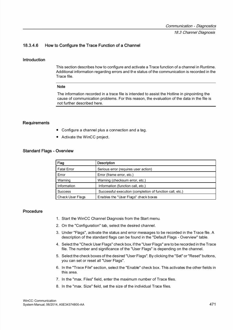
8/20/2019 WinCC Communication en-US en-US
http://slidepdf.com/reader/full/wincc-communication-en-us-en-us 471/527
18.3.4.6 How to Configure the Trace Function of a Channel
Introduction
This section describes how to configure and activate a Trace function of a channel in Runtime.Additional information regarding errors and the status of the communication is recorded in theTrace file.
Note
The information recorded in a trace file is intended to assist the Hotline in pinpointing thecause of communication problems. For this reason, the evaluation of the data in the file isnot further described here.
Requirements
● Configure a channel plus a connection and a tag.
● Activate the WinCC project.
Standard Flags - Overview
Flag Description
Fatal Error Serious error (requires user action)
Error Error (frame error, etc.)
Warning Warning (checksum error, etc.)
Information Information (function call, etc.)
Success Successful execution (completion of function call, etc.)
Check User Flags Enables the "User Flags" check boxes
Procedure
1. Start the WinCC Channel Diagnosis from the Start menu.
2. On the "Configuration" tab, select the desired channel.
3. Under "Flags", activate the status and error messages to be recorded in the Trace file. Adescription of the standard flags can be found in the "Default Flags - Overview" table.
4. Select the "Check User Flags" check box, if the "User Flags" are to be recorded in the Tracefile. The number and significance of the "User Flags" is depending on the channel.
5. Select the check boxes of the desired "User Flags". By clicking the "Set" or "Reset" buttons,you can set or reset all "User Flags".
6. In the "Trace File" section, select the "Enable" check box. This activates the other fields inthis area.
7. In the "max. Files" field, enter the maximum number of Trace files.
8. In the "max. Size" field, set the size of the individual Trace files.
Communication - Diagnostics
18.3 Channel Diagnosis
WinCC: CommunicationSystem Manual, 06/2014, A5E34374800-AA 471
8/20/2019 WinCC Communication en-US en-US
http://slidepdf.com/reader/full/wincc-communication-en-us-en-us 472/527
9. Activate the "Overwrite" field, if the channel's existing Trace files are to be overwritten -beginning with the oldest - after the maximum number of files and file size has been reached.
10.Click "Save" to save the settings and activate the changes.
18.3.4.7 How to Start Runtime
Requirements
A startup picture must be defined before Runtime is activated.
Procedure
1. Save and close all files that may be open in an editor.2. Select WinCC Explorer.
3. Activate the project by clicking the "Activate" button in the toolbar or by selecting "Activate"in the "File" menu.
See also
How to Check a Channel with Channel Diagnosis (Page 470)
Communication - Diagnostics
18.3 Channel Diagnosis
WinCC: Communication472 System Manual, 06/2014, A5E34374800-AA
8/20/2019 WinCC Communication en-US en-US
http://slidepdf.com/reader/full/wincc-communication-en-us-en-us 473/527
18.4 Diagnosis of System Info Channel
18.4.1 System Info Channel - Diagnostic Options
The following options for the diagnosis of the "System Info" channel or one of its tags areavailable:
Diagnosis of the Channel with Channel Diagnosis
"Channel Diagnosis" can query the status of the channel and connection in Runtime. Any errorsthat occur are displayed using "Error Codes".
Diagnosis of the Channel Tags
In tag management in Runtime, you can query the current value, the current quality code andthe last time that the tag was changed.
See also
How to Check a Tag (Page 476)
How to Check the Channel and the Connection (Page 474)
18.4.2 Description of Log File Entries
Introduction
The channel records errors and important status changes in the log file. These entries can beused to analyze a communication problem.
Each entry in the file has a date and time stamp followed by a flag name and description.
Example of a logbook entry:
2000-03-10 12:00:21,050 INFO Log starting ...2000-03-10 12:00:21,050 INFO | LogFileName : C:\Siemens\WinCC\Diagnose\SYSTEM_INFO_01.LOG
2000-03-10 12:00:21,050 INFO | LogFileCount : 3
2000-03-10 12:00:21,050 INFO | LogFileSize : 1400000
2000-03-10 12:00:21,050 INFO | TraceFlags : fa000001
2000-03-10 12:00:21,050 INFO start timer
2000-03-10 12:00:21,360 ERROR Illegal tag type! tag: "Format_0" correct type: "Text Tag 8-Bit Character Set"!
Communication - Diagnostics
18.4 Diagnosis of "System Info" Channel
WinCC: CommunicationSystem Manual, 06/2014, A5E34374800-AA 473
8/20/2019 WinCC Communication en-US en-US
http://slidepdf.com/reader/full/wincc-communication-en-us-en-us 474/527
Entries for INFO Flag
Message text Description
Log starting ... Start message
LogFileName : C:\ Siemens\ WinCC\Diagnose\ "channel_name".LOG
Name of the log file with path
LogFileCount : "n" Number of log files of the channel
LogFileSize : "x" Size of the individual log files in bytes
TraceFlags : fa000001 Flags used by the channel in hexadecimal format
start timer Start message
Entries for ERROR Flag
Message text Description
Illegal tag type! tag: "tag" correct type: "datatype"!
Incorrect data type of a tagtag= Name of tag with incorrect data typedata type = Correct data type
18.4.3 Determining the Cause of Incorrect Tag Values
18.4.3.1 How to Determine the Cause of Incorrect Tags
If an unexpected tag value occurs in Runtime, proceed as follows to determine the cause:
1. Check the channel and connections
2. Check the tags of the channel
See also
How to Check a Tag (Page 476)
How to Check the Channel and the Connection (Page 474)
18.4.3.2 How to Check the Channel and the Connection
Introduction
This section describes how to check the "System Info" channel and its connection in Runtime.
Requirements
● Configure a connection and tag for the "System Info" channel.
● Activate the WinCC project.
Communication - Diagnostics
18.4 Diagnosis of "System Info" Channel
WinCC: Communication474 System Manual, 06/2014, A5E34374800-AA
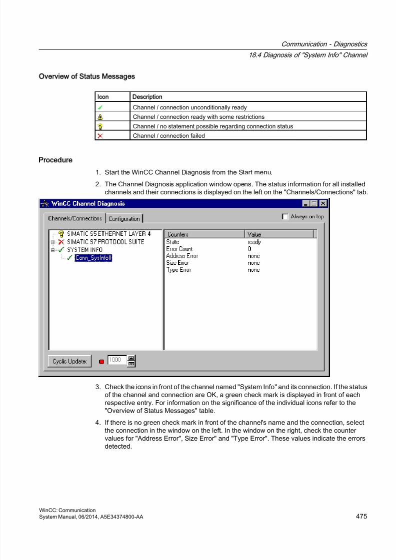
8/20/2019 WinCC Communication en-US en-US
http://slidepdf.com/reader/full/wincc-communication-en-us-en-us 475/527
Overview of Status Messages
Icon Description
Channel / connection unconditionally ready
Channel / connection ready with some restrictions
Channel / no statement possible regarding connection status
Channel / connection failed
Procedure
1. Start the WinCC Channel Diagnosis from the Start menu.
2. The Channel Diagnosis application window opens. The status information for all installedchannels and their connections is displayed on the left on the "Channels/Connections" tab.
3. Check the icons in front of the channel named "System Info" and its connection. If the status
of the channel and connection are OK, a green check mark is displayed in front of eachrespective entry. For information on the significance of the individual icons refer to the"Overview of Status Messages" table.
4. If there is no green check mark in front of the channel's name and the connection, selectthe connection in the window on the left. In the window on the right, check the countervalues for "Address Error", Size Error" and "Type Error". These values indicate the errorsdetected.
Communication - Diagnostics
18.4 Diagnosis of "System Info" Channel
WinCC: CommunicationSystem Manual, 06/2014, A5E34374800-AA 475
8/20/2019 WinCC Communication en-US en-US
http://slidepdf.com/reader/full/wincc-communication-en-us-en-us 476/527
5. Check the channel-specific log file. To do this, use a text editor to open the file in thedirectory "Siemens\WinCC\Diagnose". Check the latest entries with the "ERROR" flag. Formore information on this topic, refer to "Description of Log File Entries".
6. If you are still unable to pinpoint the error after checking the log file, please activate theTrace function and contact Customer Support.For more information on this topic, refer to "Configuring a Trace Function of a Channel".
See also
How to Configure the Trace Function of a Channel (Page 471)
Description of Log File Entries (Page 473)
How to Check a Tag (Page 476)
18.4.3.3 How to Check a Tag
Introduction
If an external tag does not have the expected value in Runtime, you can use the followingprocedure to check the tag.
Requirements
● Configure a connection and tag for the "System Info" channel.
● Activate the WinCC project.
Procedure
1. In WinCC Explorer in the tag management, select the "System Info" channel.
2. In the data window, select the external tag that you wish to check. To do this, open thedirectory structure until the tag is displayed in the table area.
3. Move the mouse pointer over the tag to be checked. A tooltip window opens showing thecurrent tag value, the quality code and the last time that the value changed.
4. Check the quality code. If value "80" is displayed, the tag value is OK. A description of the
other values can be found under "Tag quality codes".5. If the quality code is not equal to "80", select the tag in the tag management and click
"Properties" in the shortcut menu to open the "Tag Properties" dialog.
6. Check whether values have been configured for the high or low limits, the start or substitutevalues on the "Limits/Reporting" tab. These values can affect the display.
7. If the tag value is affected by one of the configured values, deactivate the project andchange the limit or substitute value.
Communication - Diagnostics
18.4 Diagnosis of "System Info" Channel
WinCC: Communication476 System Manual, 06/2014, A5E34374800-AA

8/20/2019 WinCC Communication en-US en-US
http://slidepdf.com/reader/full/wincc-communication-en-us-en-us 477/527
Note
Tag values, quality codes etc. are only displayed in Runtime.
See also
Quality Codes of Tags (Page 508)
Communication - Diagnostics
18.4 Diagnosis of "System Info" Channel
WinCC: CommunicationSystem Manual, 06/2014, A5E34374800-AA 477
8/20/2019 WinCC Communication en-US en-US
http://slidepdf.com/reader/full/wincc-communication-en-us-en-us 478/527
18.5 Diagnosis of the SIMATIC S7 Protocol Suite Channel
18.5.1 SIMATIC S7 Protocol Suite Channel - Diagnostic Options
The following options for the detection of errors and the diagnosis of the "SIMATIC S7 ProtocolSuite" channel or one of its tags are available:
Checking the Communication Processor Configuration
Besides checking the access point, the communication processor can be tested with the "SetPG/PC Interface" application. The communication processor can be checked under SIMATICNET in the same way.
Checking the Configuration of the Connection and Tags
There may be errors in the configuration of the system and connection parameters. Invalid tagvalues may also result from improperly addressing the tag in the AS.
Diagnosis of the Channel with Channel Diagnosis
"Channel Diagnosis" can query the status of the channel and connection in Runtime. Any errorsthat occur are displayed using "Error Codes".
Diagnosis of the Channel Tags
In tag management in Runtime, you can query the current value, the current quality code andthe last time that the tag was changed.
See also
How to Check a Tag (Page 487)
How to Check the Channel and the Connection (Page 485)
How to Check the Configuration of the Connection and Tags (Page 484)
Checking the Communication Processor under SIMATIC NET (Page 483)
How to Check the Configuration of the Communication Processor (Page 481)
18.5.2 Description of Log File Entries
Introduction
The channel records errors and important status changes in the log file. These entries can beused to analyze a communication problem.
Each entry in the file has a date and time stamp followed by a flag name and description.
Communication - Diagnostics
18.5 Diagnosis of the "SIMATIC S7 Protocol Suite" Channel
WinCC: Communication478 System Manual, 06/2014, A5E34374800-AA
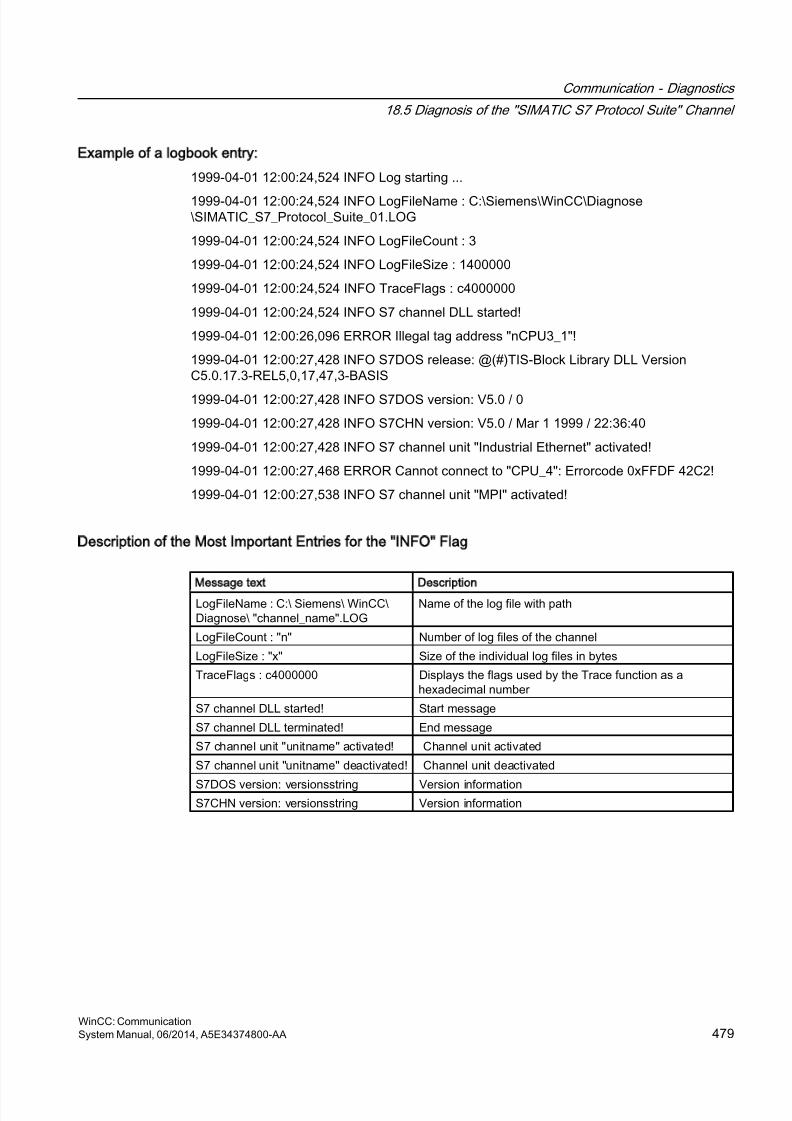
8/20/2019 WinCC Communication en-US en-US
http://slidepdf.com/reader/full/wincc-communication-en-us-en-us 479/527
Example of a logbook entry:
1999-04-01 12:00:24,524 INFO Log starting ...
1999-04-01 12:00:24,524 INFO LogFileName : C:\Siemens\WinCC\Diagnose\SIMATIC_S7_Protocol_Suite_01.LOG
1999-04-01 12:00:24,524 INFO LogFileCount : 3
1999-04-01 12:00:24,524 INFO LogFileSize : 1400000
1999-04-01 12:00:24,524 INFO TraceFlags : c4000000
1999-04-01 12:00:24,524 INFO S7 channel DLL started!
1999-04-01 12:00:26,096 ERROR Illegal tag address "nCPU3_1"!
1999-04-01 12:00:27,428 INFO S7DOS release: @(#)TIS-Block Library DLL VersionC5.0.17.3-REL5,0,17,47,3-BASIS
1999-04-01 12:00:27,428 INFO S7DOS version: V5.0 / 0
1999-04-01 12:00:27,428 INFO S7CHN version: V5.0 / Mar 1 1999 / 22:36:40
1999-04-01 12:00:27,428 INFO S7 channel unit "Industrial Ethernet" activated!
1999-04-01 12:00:27,468 ERROR Cannot connect to "CPU_4": Errorcode 0xFFDF 42C2!
1999-04-01 12:00:27,538 INFO S7 channel unit "MPI" activated!
Description of the Most Important Entries for the INFO Flag
Message text Description
LogFileName : C:\ Siemens\ WinCC\Diagnose\ "channel_name".LOG
Name of the log file with path
LogFileCount : "n" Number of log files of the channel
LogFileSize : "x" Size of the individual log files in bytes
TraceFlags : c4000000 Displays the flags used by the Trace function as ahexadecimal number
S7 channel DLL started! Start message
S7 channel DLL terminated! End message
S7 channel unit "unitname" activated! Channel unit activated
S7 channel unit "unitname" deactivated! Channel unit deactivated
S7DOS version: versionsstring Version informationS7CHN version: versionsstring Version information
Communication - Diagnostics
18.5 Diagnosis of the "SIMATIC S7 Protocol Suite" Channel
WinCC: CommunicationSystem Manual, 06/2014, A5E34374800-AA 479
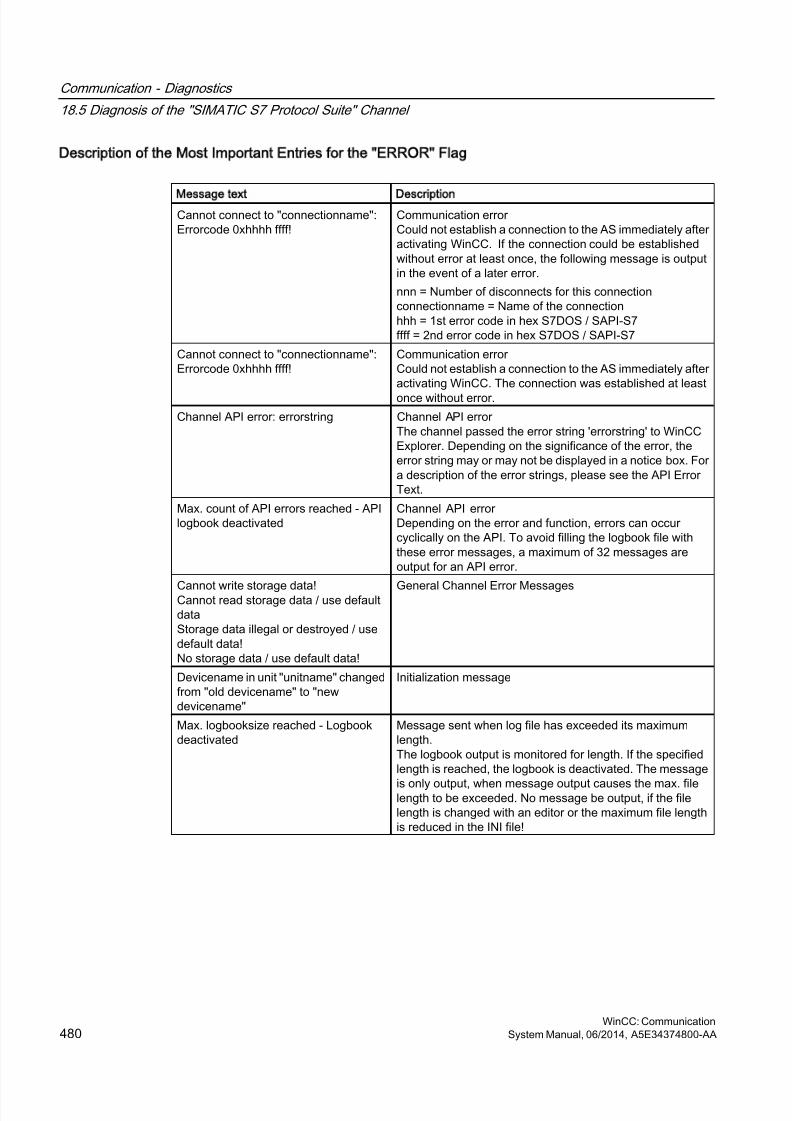
8/20/2019 WinCC Communication en-US en-US
http://slidepdf.com/reader/full/wincc-communication-en-us-en-us 480/527
Description of the Most Important Entries for the ERROR Flag
Message text Description
Cannot connect to "connectionname":Errorcode 0xhhhh ffff!
Communication error Could not establish a connection to the AS immediately afteractivating WinCC. If the connection could be establishedwithout error at least once, the following message is outputin the event of a later error.
nnn = Number of disconnects for this connectionconnectionname = Name of the connectionhhh = 1st error code in hex S7DOS / SAPI-S7ffff = 2nd error code in hex S7DOS / SAPI-S7
Cannot connect to "connectionname":Errorcode 0xhhhh ffff!
Communication error Could not establish a connection to the AS immediately afteractivating WinCC. The connection was established at leastonce without error.
Channel API error: errorstring Channel API error The channel passed the error string 'errorstring' to WinCCExplorer. Depending on the significance of the error, theerror string may or may not be displayed in a notice box. Fora description of the error strings, please see the API ErrorText.
Max. count of API errors reached - APIlogbook deactivated
Channel API error Depending on the error and function, errors can occurcyclically on the API. To avoid filling the logbook file withthese error messages, a maximum of 32 messages areoutput for an API error.
Cannot write storage data!Cannot read storage data / use defaultdataStorage data illegal or destroyed / usedefault data!No storage data / use default data!
General Channel Error Messages
Devicename in unit "unitname" changedfrom "old devicename" to "newdevicename"
Initialization message
Max. logbooksize reached - Logbookdeactivated
Message sent when log file has exceeded its maximumlength.The logbook output is monitored for length. If the specifiedlength is reached, the logbook is deactivated. The message
is only output, when message output causes the max. filelength to be exceeded. No message be output, if the filelength is changed with an editor or the maximum file lengthis reduced in the INI file!
Communication - Diagnostics
18.5 Diagnosis of the "SIMATIC S7 Protocol Suite" Channel
WinCC: Communication480 System Manual, 06/2014, A5E34374800-AA
8/20/2019 WinCC Communication en-US en-US
http://slidepdf.com/reader/full/wincc-communication-en-us-en-us 481/527
18.5.3 Determining the Cause of Incorrect Tag Values
18.5.3.1 How to Determine the Cause of Incorrect Tags
If an unexpected tag value occurs in Runtime, proceed as follows to determine the cause:
1. Checking the Configuration of the Communication Processor
2. Checking the Communication Processor under SIMATIC NET
3. Checking the Configuration of the Connection and Tags
4. Check the channel and connections
5. Check the tags of the channel
See also
How to Check a Tag (Page 487)
How to Check the Channel and the Connection (Page 485)
How to Check the Configuration of the Connection and Tags (Page 484)
Checking the Communication Processor under SIMATIC NET (Page 483)
How to Check the Configuration of the Communication Processor (Page 481)
18.5.3.2 How to Check the Configuration of the Communication Processor
Introduction
This section describes how to use the "PG/PC Port" program to check a communicationprocessor. In this example, a "CP 5613" type processor is used for the PROFIBUScommunication.
Requirements
● Install the CP 5613.
● Install the associated communication driver.
● Configure the CP 5613.
Communication - Diagnostics
18.5 Diagnosis of the "SIMATIC S7 Protocol Suite" Channel
WinCC: CommunicationSystem Manual, 06/2014, A5E34374800-AA 481
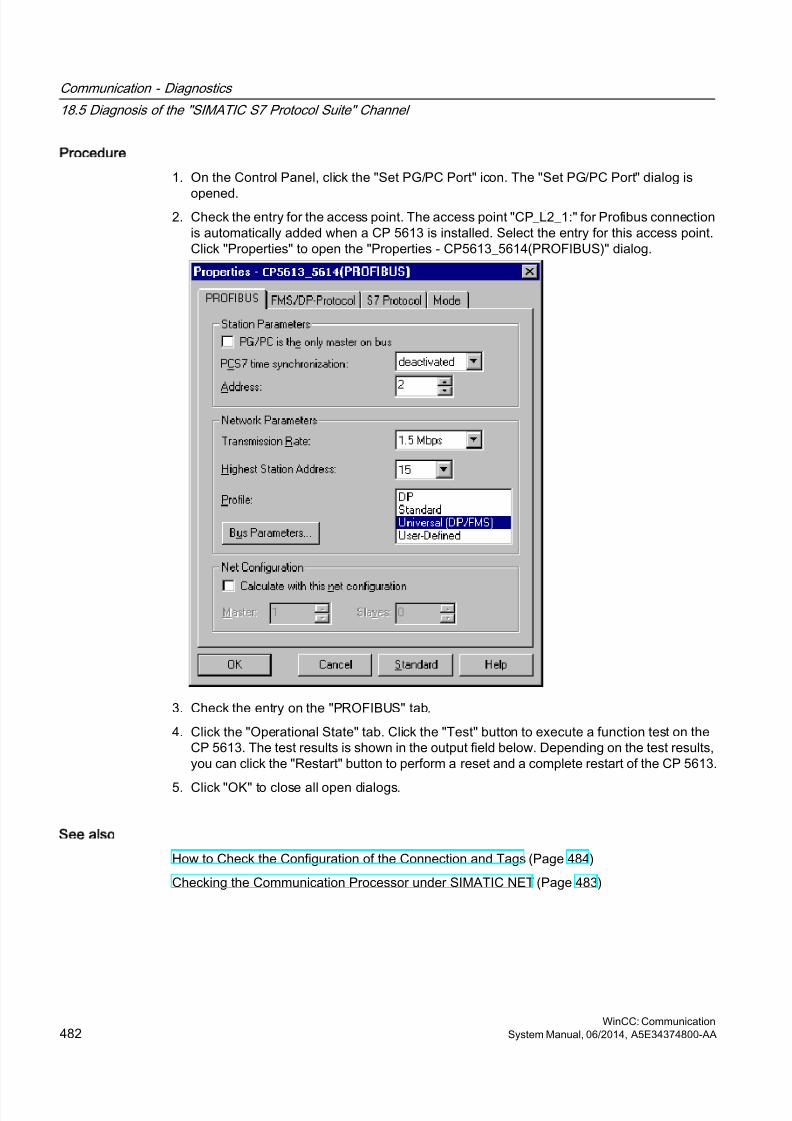
8/20/2019 WinCC Communication en-US en-US
http://slidepdf.com/reader/full/wincc-communication-en-us-en-us 482/527
Procedure
1. On the Control Panel, click the "Set PG/PC Port" icon. The "Set PG/PC Port" dialog is
opened.2. Check the entry for the access point. The access point "CP_L2_1:" for Profibus connection
is automatically added when a CP 5613 is installed. Select the entry for this access point.Click "Properties" to open the "Properties - CP5613_5614(PROFIBUS)" dialog.
3. Check the entry on the "PROFIBUS" tab.
4. Click the "Operational State" tab. Click the "Test" button to execute a function test on theCP 5613. The test results is shown in the output field below. Depending on the test results,you can click the "Restart" button to perform a reset and a complete restart of the CP 5613.
5. Click "OK" to close all open dialogs.
See also
How to Check the Configuration of the Connection and Tags (Page 484)
Checking the Communication Processor under SIMATIC NET (Page 483)
Communication - Diagnostics
18.5 Diagnosis of the "SIMATIC S7 Protocol Suite" Channel
WinCC: Communication482 System Manual, 06/2014, A5E34374800-AA
8/20/2019 WinCC Communication en-US en-US
http://slidepdf.com/reader/full/wincc-communication-en-us-en-us 483/527
18.5.3.3 Checking the Communication Processor under SIMATIC NET
Introduction
This section explains how to check a communication processor using the "Set PC Station"program in the SIMATIC NET software.
In this example, the "CP 5613" for the PROFIBUS communication is used to the "SIMATIC S7Protocol Suite" channel.
Requirements
● Install the CP 5613.
● Install the SIMATIC NET software. For Windows 2000, a version from V6.0 SP5 is required,
with Windows XP a version from V6.1 must be installed.● Configure the CP 5613 under SIMATIC NET.
Procedure
1. Activate the Windows Start menu, open "SIMATIC / SIMATIC NET / Settings" and selectmenu item "Set PC Station". The "Configurations Console PC Station" dialog opens.
2. Check the entry for the access point. Select the "Access Point" directory in the navigationwindow. The existing access points are listed in the data window. Upon installation of theCP 5613, access point "CP_L2_1:" for PROFIBUS communication is added automatically.Select this access point in the data window. Use the "Properties" menu item from the
shortcut menu to open the "Properties of CP_L2_1:" dialog.
3. Check the entry in the "Assigned Interface Parameters" field. In the case of a CP5613 in aPROFIBUS network, select entry "CP5613_5614(PROFIBUS)".
4. Open the navigation window, select the "Components" directory and then the "CP5613/CP5614" subdirectory.
5. Select the "Network Diagnosis" directory. Click the "Test" button to execute a function teston the CP 5613. The result is displayed in the output window. Depending on the test results,click the "Restart" button in the "General" directory to perform a reset and then a completerestart of the CP 5613.
6. Check the list of participants connected to PROFIBUS in the list in the "Bus Participants"
directory. Based on the display, it is possible to determine the function and status of yourown station as well as other participants which are connected.
7. Close the dialog.
8. If a fault is detected in the configuration of the communication processor, modifications canonly be made to the configuration using SIMATIC NET tools. Further information is availableunder SIMATIC NET.
See also
How to Check the Configuration of the Connection and Tags (Page 484)
Communication - Diagnostics
18.5 Diagnosis of the "SIMATIC S7 Protocol Suite" Channel
WinCC: CommunicationSystem Manual, 06/2014, A5E34374800-AA 483

8/20/2019 WinCC Communication en-US en-US
http://slidepdf.com/reader/full/wincc-communication-en-us-en-us 484/527
18.5.3.4 How to Check the Configuration of the Connection and Tags
Introduction
This section describes how to check the system parameters and the configuration of theconnection and tags. In this example, a "CP 5613" communication processor is used for thePROFIBUS communication.
Requirements
● Install the CP 5613.
● Install the associated communication driver.
● Configure the CP 5613.
● Configure a connection and tag for the "SIMATIC S7 Protocol Suite" channel.
● Activate the WinCC project.
Procedure
1. In WinCC Explorer in the tag management, select the "SIMATIC S7 Protocol Suite" channel.In the data window, select the "PROFIBUS" channel unit. In the channel unit shortcut menu,click "System Parameters". The "System Parameters - PROFIBUS" dialog opens.
2. On the "Unit" tab, check the entry in the "Logical Device Name" field. By default, this is setto the access point "CP_L2_1:" . The access point is assigned during installation of the
communication processor in the CP 5613 system. Close the dialog.
3. In the tag management navigation window, select the "PROFIBUS" channel unit. In thedata window, select the connection to be checked. In the shortcut menu, click "Properties"to open the "Connection Properties" dialog.
4. Click the "Properties" button to open the "Connection Parameters - PROFIBUS" dialog.
5. Check the settings on the "Connection" tab. Close the open dialogs.
Communication - Diagnostics
18.5 Diagnosis of the "SIMATIC S7 Protocol Suite" Channel
WinCC: Communication484 System Manual, 06/2014, A5E34374800-AA
8/20/2019 WinCC Communication en-US en-US
http://slidepdf.com/reader/full/wincc-communication-en-us-en-us 485/527
6. In the navigation window, select the checked connection. In the data window, select thetag to be checked. In the shortcut menu, click "Properties" to open the "Tag Properties"dialog. Check the values in the "Type Conversion" and "Data Type" fields.
7. Click the "Select" button to open the "Address properties" dialog. Check the settings foraddressing the tag in the AS.
8. Click "OK" to close all open dialogs.
See also
How to Check the Channel and the Connection (Page 485)
18.5.3.5 How to Check the Channel and the Connection
Introduction
This section describes how to check the "SIMATIC S7 Protocol Suite" channel and itsconnection in Runtime.
Requirements
● Install a communication processor in a WinCC computer, for example the CP 5613 forPROFIBUS communication.
● Install the associated communication driver.
● Configure the CP 5613.
● Create a STEP7 project.
● Configure a connection and tag for the "SIMATIC S7 Protocol Suite" channel.
● Activate the WinCC project.
Overview of Status Messages
Icon Description
Channel / connection unconditionally ready
Channel / connection ready with some restrictions
Channel / no statement possible regarding connection status
Channel / connection failed
Communication - Diagnostics
18.5 Diagnosis of the "SIMATIC S7 Protocol Suite" Channel
WinCC: CommunicationSystem Manual, 06/2014, A5E34374800-AA 485
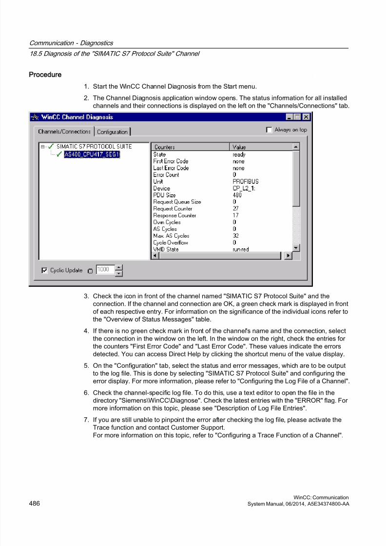
8/20/2019 WinCC Communication en-US en-US
http://slidepdf.com/reader/full/wincc-communication-en-us-en-us 486/527
Procedure
1. Start the WinCC Channel Diagnosis from the Start menu.
2. The Channel Diagnosis application window opens. The status information for all installedchannels and their connections is displayed on the left on the "Channels/Connections" tab.
3. Check the icon in front of the channel named "SIMATIC S7 Protocol Suite" and theconnection. If the channel and connection are OK, a green check mark is displayed in frontof each respective entry. For information on the significance of the individual icons refer tothe "Overview of Status Messages" table.
4. If there is no green check mark in front of the channel's name and the connection, selectthe connection in the window on the left. In the window on the right, check the entries forthe counters "First Error Code" and "Last Error Code". These values indicate the errorsdetected. You can access Direct Help by clicking the shortcut menu of the value display.
5. On the "Configuration" tab, select the status and error messages, which are to be outputto the log file. This is done by selecting "SIMATIC S7 Protocol Suite" and configuring the
error display. For more information, please refer to "Configuring the Log File of a Channel".6. Check the channel-specific log file. To do this, use a text editor to open the file in the
directory "Siemens\WinCC\Diagnose". Check the latest entries with the "ERROR" flag. Formore information on this topic, please see "Description of Log File Entries".
7. If you are still unable to pinpoint the error after checking the log file, please activate theTrace function and contact Customer Support.For more information on this topic, refer to "Configuring a Trace Function of a Channel".
Communication - Diagnostics
18.5 Diagnosis of the "SIMATIC S7 Protocol Suite" Channel
WinCC: Communication486 System Manual, 06/2014, A5E34374800-AA
8/20/2019 WinCC Communication en-US en-US
http://slidepdf.com/reader/full/wincc-communication-en-us-en-us 487/527
See also
How to Configure the Trace Function of a Channel (Page 471)
Description of Log File Entries (Page 478)
How to Check a Tag (Page 487)
18.5.3.6 How to Check a Tag
Introduction
If an external tag does not have the expected value in Runtime, you can use the followingprocedure to check the tag.
In a "SIMATIC S7 Protocol Suite" channel, you can also use connection-specific internal tags.This procedure can also be used to check these tags.
Requirements
● Install a communication module on a WinCC computer, for example the CP 5613 for MPIcommunication.
● Install the associated communication driver.
● Configure the CP 5613.
● Create a STEP7 project.
● Configure a connection and tag for the "SIMATIC S7 Protocol Suite" channel.● Activate the WinCC project.
Procedure
1. In WinCC Explorer in the tag management, select the "SIMATIC S7 Protocol Suite" channel.
2. In the data window, select the external tag that you wish to check. To do this, open thedirectory structure until the tag is displayed in the table area.
3. Move the mouse pointer over the tag to be checked. A tooltip window opens showing thecurrent tag value, the quality code and the last time that the value changed.
4. Check the quality code. If value "80" is displayed, the tag value is OK. A description of theother values can be found under "Tag quality codes".
5. If the quality code is not equal to "80", select the tag in the tag management and click"Properties" in the shortcut menu to open the "Tag Properties" dialog.
6. Check whether values have been configured for the high or low limits, the start or substitutevalues on the "Limits/Reporting" tab. These values can affect the display.
7. If the tag value is affected by one of the configured values, deactivate the project andchange the limit or substitute value.
Communication - Diagnostics
18.5 Diagnosis of the "SIMATIC S7 Protocol Suite" Channel
WinCC: CommunicationSystem Manual, 06/2014, A5E34374800-AA 487

8/20/2019 WinCC Communication en-US en-US
http://slidepdf.com/reader/full/wincc-communication-en-us-en-us 488/527
Note
In Runtime, the current values of the connection-specific internal tags can be viewed in detailwith "WinCC Channel Diagnostics". When the main connection is selected, the tags is shownin the "Counter" column.
Tag values, quality codes etc. are only displayed in Runtime.
See also
Quality Codes of Tags (Page 508)
Communication - Diagnostics
18.5 Diagnosis of the "SIMATIC S7 Protocol Suite" Channel
WinCC: Communication488 System Manual, 06/2014, A5E34374800-AA
8/20/2019 WinCC Communication en-US en-US
http://slidepdf.com/reader/full/wincc-communication-en-us-en-us 489/527
18.6 Diagnosis of the SIMATIC S5 Profibus FDL Channel
18.6.1 Diagnostic Options for the SIMATIC S5 PROFIBUS FDL Channel
The following options for the detection of errors and the diagnosis of the "SIMATIC S5PROFIBUS FDL" channel or one of its tags:
Checking the Communication Processor Configuration
Besides checking the access point, the communication processor can be tested with the "SetPG/PC Interface" application. The communication processor can be checked under SIMATICNET in the same way.
Checking the Configuration of the Connection and Tags
There may be errors in the configuration of the system and connection parameters. Invalid tagvalues may also result from improperly addressing the tag in the AS.
Diagnosis of the Channel with Channel Diagnosis
"Channel Diagnosis" can query the status of the channel and connection in Runtime. Any errorsthat occur are displayed using "Error Codes".
Diagnosis of the Channel Tags
In tag management in Runtime, you can query the current value, the current quality code andthe last time that the tag was changed.
See also
How to Check a Tag (Page 497)
How to Check the Channel and the Connection (Page 495)
How to Check the Configuration of the Connection and Tags (Page 493)
Checking the Communication Processor under SIMATIC NET (Page 492)
How to Check the Configuration of the Communication Processor (Page 491)
18.6.2 Description of Log File Entries
Introduction
The channel records errors and important status changes in the log file. These entries can beused to analyze a communications problem.
Each entry in the file has a date and time stamp followed by a flag name and description.
Communication - Diagnostics
18.6 Diagnosis of the "SIMATIC S5 Profibus FDL" Channel
WinCC: CommunicationSystem Manual, 06/2014, A5E34374800-AA 489
8/20/2019 WinCC Communication en-US en-US
http://slidepdf.com/reader/full/wincc-communication-en-us-en-us 490/527
Example of a logbook entry:
2000-05-03 14:43:48,733 INFO Log starting ...
2000-05-03 14:43:48,733 INFO | LogFileName : d:\Siemens\WinCC\Diagnose\SIMATIC_S5_PROFIBUS_FDL_01.LOG
2000-05-03 14:43:48,733 INFO | LogFileCount : 3
2000-05-03 14:43:48,733 INFO | LogFileSize : 1400000
2000-05-03 14:43:48,733 INFO | TraceFlags : fa017fff
Description of the INFO Flag Entries
Message text Description
Log starting ... Start message
LogFileName : C:\ Siemens\ WinCC\Diagnose\ "channel_name".LOG
Name of the log file with path
LogFileCount : "n" Number of log files of the channel
LogFileSize : "x" Size of the individual log files in bytes
TraceFlags : fa017fff Displays the flags used by the Trace function as ahexadecimal number
18.6.3 Determining the Cause of Incorrect Tag Values
18.6.3.1 How to Determine the Cause of Incorrect Tags
If an unexpected tag value occurs in Runtime, proceed as follows to determine the cause:
1. Check the configuration of the communication processor
2. Check the communication processor under SIMATIC NET
3. Check the configuration of the connection and tags
4. Check the channel and connections
5. Check the tags of the channel
See also
How to Check the Configuration of the Connection and Tags (Page 493)
How to Check a Tag (Page 497)
How to Check the Channel and the Connection (Page 495)
Checking the Communication Processor under SIMATIC NET (Page 492)
How to Check the Configuration of the Communication Processor (Page 491)
Communication - Diagnostics
18.6 Diagnosis of the "SIMATIC S5 Profibus FDL" Channel
WinCC: Communication490 System Manual, 06/2014, A5E34374800-AA
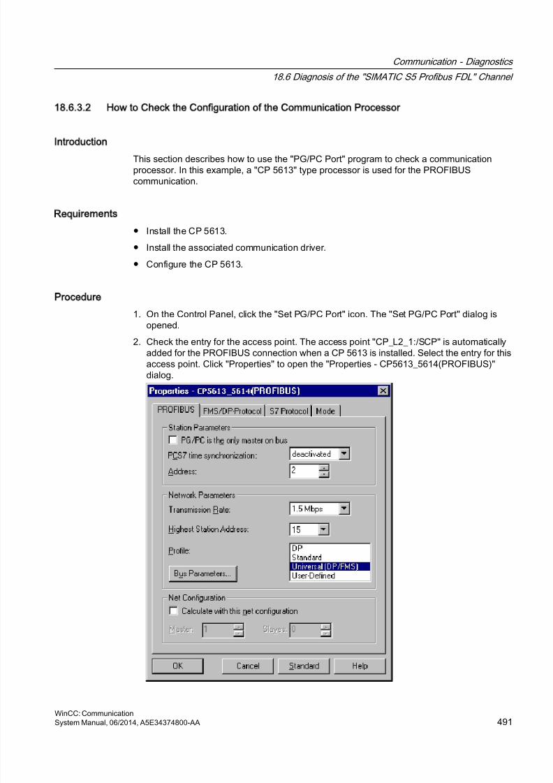
8/20/2019 WinCC Communication en-US en-US
http://slidepdf.com/reader/full/wincc-communication-en-us-en-us 491/527
18.6.3.2 How to Check the Configuration of the Communication Processor
Introduction
This section describes how to use the "PG/PC Port" program to check a communicationprocessor. In this example, a "CP 5613" type processor is used for the PROFIBUScommunication.
Requirements
● Install the CP 5613.
● Install the associated communication driver.
● Configure the CP 5613.
Procedure
1. On the Control Panel, click the "Set PG/PC Port" icon. The "Set PG/PC Port" dialog isopened.
2. Check the entry for the access point. The access point "CP_L2_1:/SCP" is automaticallyadded for the PROFIBUS connection when a CP 5613 is installed. Select the entry for thisaccess point. Click "Properties" to open the "Properties - CP5613_5614(PROFIBUS)"dialog.
Communication - Diagnostics
18.6 Diagnosis of the "SIMATIC S5 Profibus FDL" Channel
WinCC: CommunicationSystem Manual, 06/2014, A5E34374800-AA 491
8/20/2019 WinCC Communication en-US en-US
http://slidepdf.com/reader/full/wincc-communication-en-us-en-us 492/527
3. Check the entry on the "PROFIBUS" tab.
4. Click the "Operational State" tab. Click the "Test" button to execute a function test on the
CP 5613. The test results is shown in the output field below. Depending on the test results,you can click the "Restart" button to perform a reset and a complete restart of the CP 5613.
5. Click "OK" to close all open dialogs.
See also
How to Check the Configuration of the Connection and Tags (Page 493)
Checking the Communication Processor under SIMATIC NET (Page 492)
18.6.3.3 Checking the Communication Processor under SIMATIC NET
Introduction
This section explains how to check a communication processor using the "Set PC Station"program in the SIMATIC NET software.
In this example, the "CP 5613" type is used for the PROFIBUS communication to channel"SIMATIC S5 PROFIBUS FDL".
Requirements
● Install the CP 5613.
● Install the SIMATIC NET software. For Windows 2000, a version from V6.0 SP5 is required,with Windows XP a version from V6.1 must be installed.
● Configure the CP 5613 under SIMATIC NET.
Procedure
1. Activate the Windows Start menu, open "SIMATIC / SIMATIC NET / Settings" and selectmenu item "Set PC Station". The "Configurations Console PC Station" dialog opens.
2. Check the entry for the access point. Select the "Access Point" directory in the navigationwindow. The existing access points are listed in the data window. Upon installation of the
CP 5613, access point "CP_L2_1:" for PROFIBUS communication is added automatically.Select this access point in the data window. Use the "Properties" menu item from theshortcut menu to open the "Properties of CP_L2_1:" dialog.
3. Check the entry in the "Assigned Interface Parameters" field. In the case of a CP5613 in aPROFIBUS network, select entry "CP5613_5614(PROFIBUS)".
4. Open the navigation window, select the "Components" directory and then the "CP5613/CP5614" subdirectory.
5. Select the "Network Diagnosis" directory. Click the "Test" button to execute a function teston the CP 5613. The result is displayed in the output window. Depending on the test results,click the "Restart" button in the "General" directory to perform a reset and then a completerestart of the CP 5613.
Communication - Diagnostics
18.6 Diagnosis of the "SIMATIC S5 Profibus FDL" Channel
WinCC: Communication492 System Manual, 06/2014, A5E34374800-AA
8/20/2019 WinCC Communication en-US en-US
http://slidepdf.com/reader/full/wincc-communication-en-us-en-us 493/527
6. Check the list of participants connected to PROFIBUS in the list in the "Bus Participants"directory. Based on the display, it is possible to determine the function and status of yourown station as well as other participants which are connected.
7. Close the dialog.
8. If a fault is detected in the configuration of the communication processor, modifications canonly be made to the configuration using SIMATIC NET tools. Further information is availableunder SIMATIC NET.
See also
How to Check the Configuration of the Connection and Tags (Page 493)
18.6.3.4 How to Check the Configuration of the Connection and Tags
Introduction
This section describes how to check the system parameters and the configuration of theconnection and tags.
Requirements
● Install the CP 5613.
● Install the communication driver.
● Configure the CP 5613.
● Configure a connection and tag for the "SIMATIC S5 PROFIBUS FDL" channel.
● Activate the WinCC project.
Communication - Diagnostics
18.6 Diagnosis of the "SIMATIC S5 Profibus FDL" Channel
WinCC: CommunicationSystem Manual, 06/2014, A5E34374800-AA 493
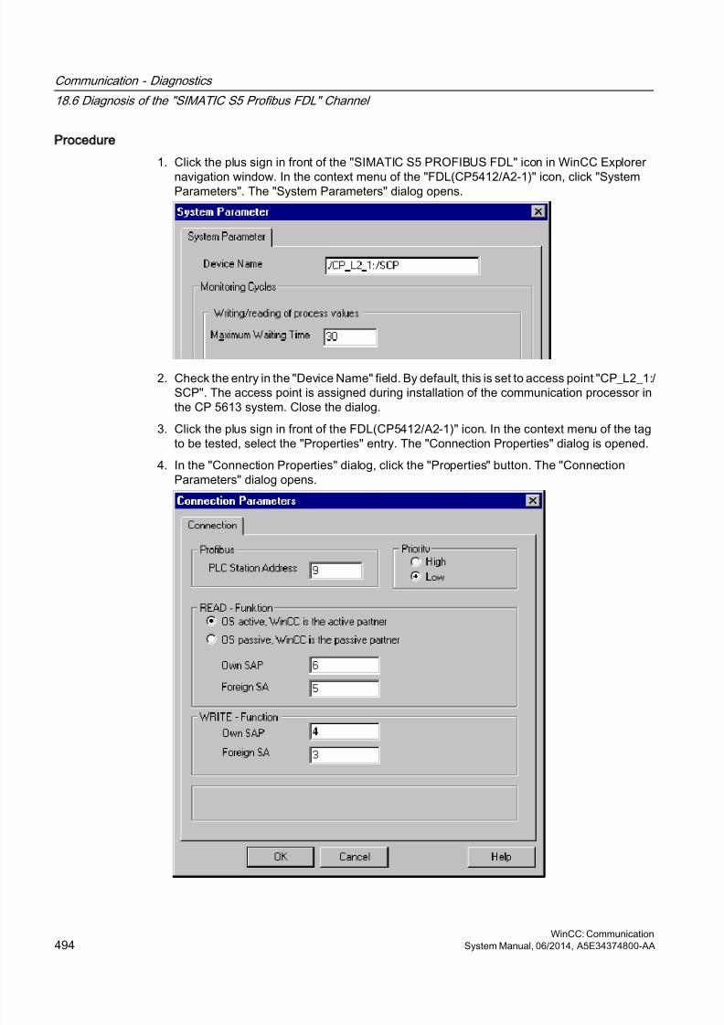
8/20/2019 WinCC Communication en-US en-US
http://slidepdf.com/reader/full/wincc-communication-en-us-en-us 494/527
Procedure
1. Click the plus sign in front of the "SIMATIC S5 PROFIBUS FDL" icon in WinCC Explorer
navigation window. In the context menu of the "FDL(CP5412/A2-1)" icon, click "SystemParameters". The "System Parameters" dialog opens.
2. Check the entry in the "Device Name" field. By default, this is set to access point "CP_L2_1:/SCP". The access point is assigned during installation of the communication processor inthe CP 5613 system. Close the dialog.
3. Click the plus sign in front of the FDL(CP5412/A2-1)" icon. In the context menu of the tagto be tested, select the "Properties" entry. The "Connection Properties" dialog is opened.
4. In the "Connection Properties" dialog, click the "Properties" button. The "ConnectionParameters" dialog opens.
Communication - Diagnostics
18.6 Diagnosis of the "SIMATIC S5 Profibus FDL" Channel
WinCC: Communication494 System Manual, 06/2014, A5E34374800-AA
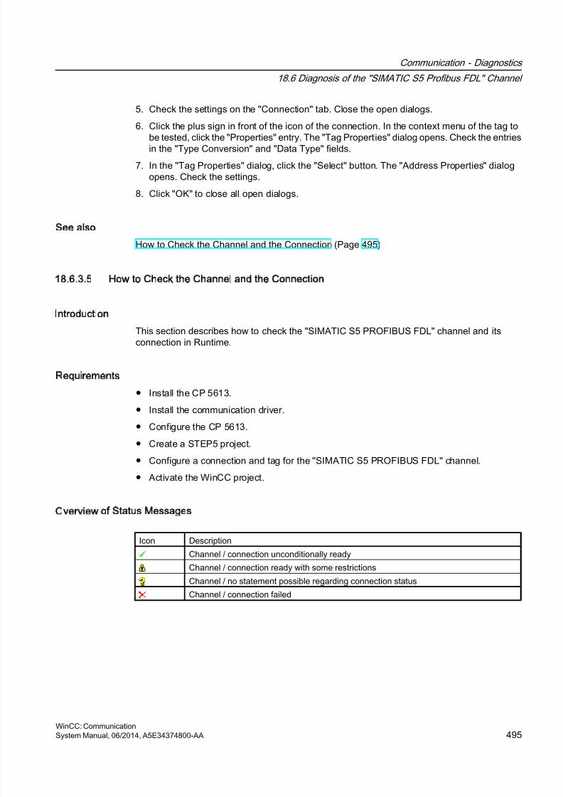
8/20/2019 WinCC Communication en-US en-US
http://slidepdf.com/reader/full/wincc-communication-en-us-en-us 495/527
5. Check the settings on the "Connection" tab. Close the open dialogs.
6. Click the plus sign in front of the icon of the connection. In the context menu of the tag to
be tested, click the "Properties" entry. The "Tag Properties" dialog opens. Check the entriesin the "Type Conversion" and "Data Type" fields.
7. In the "Tag Properties" dialog, click the "Select" button. The "Address Properties" dialogopens. Check the settings.
8. Click "OK" to close all open dialogs.
See also
How to Check the Channel and the Connection (Page 495)
18.6.3.5 How to Check the Channel and the Connection
Introduction
This section describes how to check the "SIMATIC S5 PROFIBUS FDL" channel and itsconnection in Runtime.
Requirements
● Install the CP 5613.
● Install the communication driver.
● Configure the CP 5613.
● Create a STEP5 project.
● Configure a connection and tag for the "SIMATIC S5 PROFIBUS FDL" channel.
● Activate the WinCC project.
Overview of Status Messages
Icon Description
Channel / connection unconditionally readyChannel / connection ready with some restrictions
Channel / no statement possible regarding connection status
Channel / connection failed
Communication - Diagnostics
18.6 Diagnosis of the "SIMATIC S5 Profibus FDL" Channel
WinCC: CommunicationSystem Manual, 06/2014, A5E34374800-AA 495
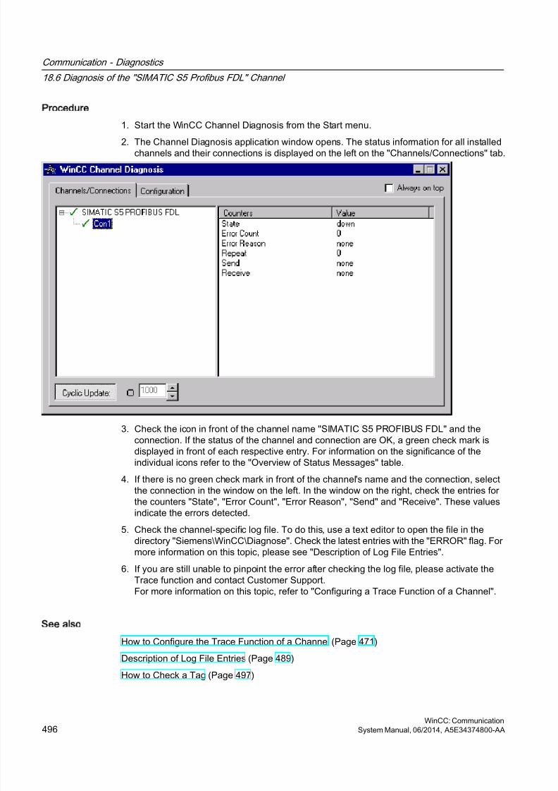
8/20/2019 WinCC Communication en-US en-US
http://slidepdf.com/reader/full/wincc-communication-en-us-en-us 496/527
Procedure
1. Start the WinCC Channel Diagnosis from the Start menu.
2. The Channel Diagnosis application window opens. The status information for all installedchannels and their connections is displayed on the left on the "Channels/Connections" tab.
3. Check the icon in front of the channel name "SIMATIC S5 PROFIBUS FDL" and theconnection. If the status of the channel and connection are OK, a green check mark isdisplayed in front of each respective entry. For information on the significance of theindividual icons refer to the "Overview of Status Messages" table.
4. If there is no green check mark in front of the channel's name and the connection, selectthe connection in the window on the left. In the window on the right, check the entries forthe counters "State", "Error Count", "Error Reason", "Send" and "Receive". These valuesindicate the errors detected.
5. Check the channel-specific log file. To do this, use a text editor to open the file in thedirectory "Siemens\WinCC\Diagnose". Check the latest entries with the "ERROR" flag. For
more information on this topic, please see "Description of Log File Entries".6. If you are still unable to pinpoint the error after checking the log file, please activate the
Trace function and contact Customer Support.For more information on this topic, refer to "Configuring a Trace Function of a Channel".
See also
How to Configure the Trace Function of a Channel (Page 471)
Description of Log File Entries (Page 489)
How to Check a Tag (Page 497)
Communication - Diagnostics
18.6 Diagnosis of the "SIMATIC S5 Profibus FDL" Channel
WinCC: Communication496 System Manual, 06/2014, A5E34374800-AA
8/20/2019 WinCC Communication en-US en-US
http://slidepdf.com/reader/full/wincc-communication-en-us-en-us 497/527
18.6.3.6 How to Check a Tag
Introduction
If an external tag does not have the expected value in Runtime, you can use the followingprocedure to check the tag.
Requirements
● Install the CP 5613.
● Install the communication driver.
● Configure the CP 5613.
● Create a STEP5 project.● Configure a connection and tag for the "SIMATIC S5 PROFIBUS FDL" channel.
● Activate the WinCC project.
Procedure
1. In WinCC Explorer in tag management, select the "SIMATIC S5 PROFIBUS FDL" channel.
2. In the data window, select the external tag that you wish to check. To do this, open thedirectory structure until the tag is displayed in the table area.
3. Move the mouse pointer over the tag to be checked. A tooltip window opens showing the
current tag value, the quality code and the last time that the value changed.4. Check the quality code. If value "80" is displayed, the tag value is OK. A description of the
other values can be found under "Tag quality codes".
5. If the quality code is not equal to "80", select the tag in the tag management and click"Properties" in the shortcut menu to open the "Tag Properties" dialog.
6. Check whether values have been configured for the high or low limits, the start or substitutevalues on the "Limits/Reporting" tab. These values can affect the display.
7. If the tag value is affected by one of the configured values, deactivate the project andchange the limit or substitute value.
Note
Tag values, quality codes etc. are only displayed in Runtime.
See also
Quality Codes of Tags (Page 508)
Communication - Diagnostics
18.6 Diagnosis of the "SIMATIC S5 Profibus FDL" Channel
WinCC: CommunicationSystem Manual, 06/2014, A5E34374800-AA 497
8/20/2019 WinCC Communication en-US en-US
http://slidepdf.com/reader/full/wincc-communication-en-us-en-us 498/527
18.7 Diagnosis of the OPC Channel
18.7.1 Possibilities for Diagnosing the OPC Channel
There are the following possibilities for detecting errors and diagnosing the "OPC" channel orone of its tags:
Checking the Configuration of the Connection and Tags
There may be errors in the configuration of the system and connection parameters. Invalid tagvalues may also result from improperly addressing the tag in the AS.
Diagnosis of the Channel with Channel Diagnosis
"Channel Diagnosis" can query the status of the channel and connection in Runtime. Any errorsthat occur are displayed using "Error Codes".
Diagnosis of the Channel Tags
In tag management in Runtime, you can query the current value, the current quality code andthe last time that the tag was changed.
See also
How to Check a Tag (Page 505)
How to Check the Channel and the Connection (Page 503)
How to Check the Configuration Data (Page 502)
18.7.2 Description of Log File Entries
18.7.2.1 Description of Log File Entries
Introduction
The channel records errors and important status changes in the log file. The following sectionscover only the most important entries. These entries can be used to analyze a communicationsproblem.
A distinction must be made between two types of entries:
● INFO
● ERROR
Communication - Diagnostics
18.7 Diagnosis of the "OPC" Channel
WinCC: Communication498 System Manual, 06/2014, A5E34374800-AA
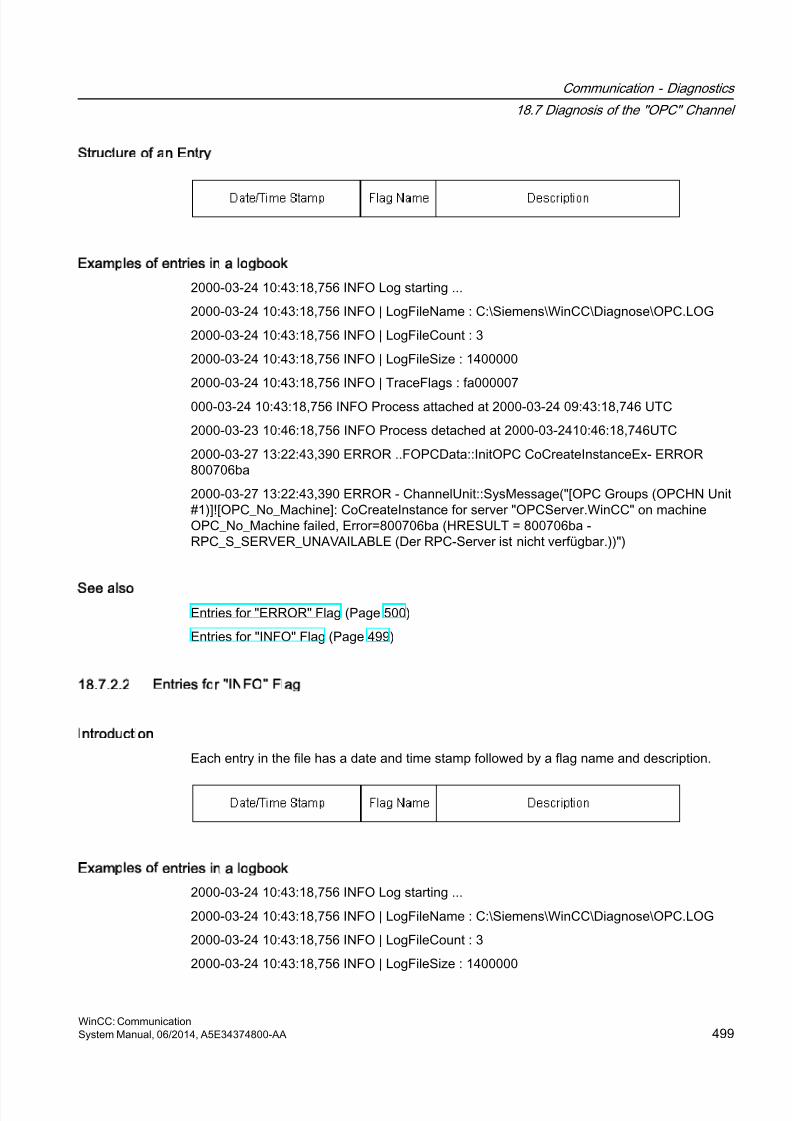
8/20/2019 WinCC Communication en-US en-US
http://slidepdf.com/reader/full/wincc-communication-en-us-en-us 499/527
Structure of an Entry
Examples of entries in a logbook
2000-03-24 10:43:18,756 INFO Log starting ...
2000-03-24 10:43:18,756 INFO | LogFileName : C:\Siemens\WinCC\Diagnose\OPC.LOG
2000-03-24 10:43:18,756 INFO | LogFileCount : 3
2000-03-24 10:43:18,756 INFO | LogFileSize : 1400000
2000-03-24 10:43:18,756 INFO | TraceFlags : fa000007
000-03-24 10:43:18,756 INFO Process attached at 2000-03-24 09:43:18,746 UTC
2000-03-23 10:46:18,756 INFO Process detached at 2000-03-2410:46:18,746UTC
2000-03-27 13:22:43,390 ERROR ..FOPCData::InitOPC CoCreateInstanceEx- ERROR800706ba
2000-03-27 13:22:43,390 ERROR - ChannelUnit::SysMessage("[OPC Groups (OPCHN Unit#1)]![OPC_No_Machine]: CoCreateInstance for server "OPCServer.WinCC" on machineOPC_No_Machine failed, Error=800706ba (HRESULT = 800706ba -RPC_S_SERVER_UNAVAILABLE (Der RPC-Server ist nicht verfügbar.))")
See also
Entries for "ERROR" Flag (Page 500)
Entries for "INFO" Flag (Page 499)
18.7.2.2 Entries for INFO Flag
Introduction
Each entry in the file has a date and time stamp followed by a flag name and description.
Examples of entries in a logbook
2000-03-24 10:43:18,756 INFO Log starting ...
2000-03-24 10:43:18,756 INFO | LogFileName : C:\Siemens\WinCC\Diagnose\OPC.LOG
2000-03-24 10:43:18,756 INFO | LogFileCount : 3
2000-03-24 10:43:18,756 INFO | LogFileSize : 1400000
Communication - Diagnostics
18.7 Diagnosis of the "OPC" Channel
WinCC: CommunicationSystem Manual, 06/2014, A5E34374800-AA 499
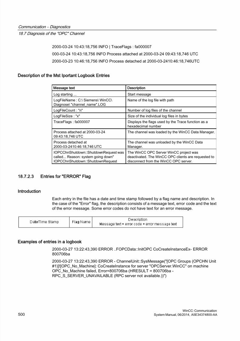
8/20/2019 WinCC Communication en-US en-US
http://slidepdf.com/reader/full/wincc-communication-en-us-en-us 500/527
2000-03-24 10:43:18,756 INFO | TraceFlags : fa000007
000-03-24 10:43:18,756 INFO Process attached at 2000-03-24 09:43:18,746 UTC
2000-03-23 10:46:18,756 INFO Process detached at 2000-03-2410:46:18,746UTC
Description of the Mst Iportant Logbook Entries
Message text Description
Log starting ... Start message
LogFileName : C:\ Siemens\ WinCC\Diagnose\ "channel_name".LOG
Name of the log file with path
LogFileCount : "n" Number of log files of the channel
LogFileSize : "x" Size of the individual log files in bytes
TraceFlags : fa000007 Displays the flags used by the Trace function as ahexadecimal number
Process attached at 2000-03-2409:43:18,746 UTC
The channel was loaded by the WinCC Data Manager.
Process detached at2000-03-2410:46:18,746 UTC
The channel was unloaded by the WinCC DataManager.
IOPCChnShutdown::ShutdownRequest wascalled... Reason: system going down"IOPCChnShutdown::ShutdownRequest
The WinCC OPC Server WinCC project wasdeactivated. The WinCC OPC clients are requested todisconnect from the WinCC OPC server.
18.7.2.3 Entries for ERROR Flag
Introduction
Each entry in the file has a date and time stamp followed by a flag name and description. Inthe case of the "Error" flag, the description consists of a message text, error code and the textof the error message. Some error codes do not have text for an error message.
Examples of entries in a logbook
2000-03-27 13:22:43,390 ERROR ..FOPCData::InitOPC CoCreateInstanceEx- ERROR800706ba
2000-03-27 13:22:43,390 ERROR - ChannelUnit::SysMessage("[OPC Groups (OPCHN Unit#1)]![OPC_No_Machine]: CoCreateInstance for server "OPCServer.WinCC" on machineOPC_No_Machine failed, Error=800706ba (HRESULT = 800706ba -RPC_S_SERVER_UNAVAILABLE (RPC server not available.))")
Communication - Diagnostics
18.7 Diagnosis of the "OPC" Channel
WinCC: Communication500 System Manual, 06/2014, A5E34374800-AA
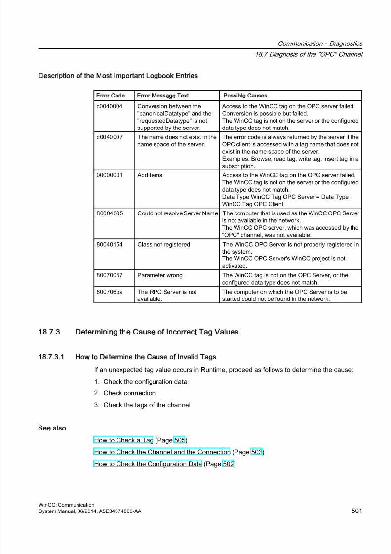
8/20/2019 WinCC Communication en-US en-US
http://slidepdf.com/reader/full/wincc-communication-en-us-en-us 501/527
Description of the Most Important Logbook Entries
Error Code Error Message Text Possible Causes
c0040004 Conversion between the"canonicalDatatype" and the"requestedDatatype" is notsupported by the server.
Access to the WinCC tag on the OPC server failed.Conversion is possible but failed.The WinCC tag is not on the server or the configureddata type does not match.
c0040007 The name does not exist in thename space of the server.
The error code is always returned by the server if theOPC client is accessed with a tag name that does notexist in the name space of the server.Examples: Browse, read tag, write tag, insert tag in asubscription.
00000001 AddItems Access to the WinCC tag on the OPC server failed.The WinCC tag is not on the server or the configureddata type does not match.Data Type WinCC Tag OPC Server = Data TypeWinCC Tag OPC Client.
80004005 Could not resolve Server Name The computer that is used as the WinCC OPC Serveris not available in the network.The WinCC OPC server, which was accessed by the"OPC" channel, was not available.
80040154 Class not registered The WinCC OPC Server is not properly registered inthe system.The WinCC OPC Server's WinCC project is notactivated.
80070057 Parameter wrong The WinCC tag is not on the OPC Server, or theconfigured data type does not match.
800706ba The RPC Server is notavailable.
The computer on which the OPC Server is to bestarted could not be found in the network.
18.7.3 Determining the Cause of Incorrect Tag Values
18.7.3.1 How to Determine the Cause of Invalid Tags
If an unexpected tag value occurs in Runtime, proceed as follows to determine the cause:
1. Check the configuration data
2. Check connection
3. Check the tags of the channel
See also
How to Check a Tag (Page 505)
How to Check the Channel and the Connection (Page 503)
How to Check the Configuration Data (Page 502)
Communication - Diagnostics
18.7 Diagnosis of the "OPC" Channel
WinCC: CommunicationSystem Manual, 06/2014, A5E34374800-AA 501
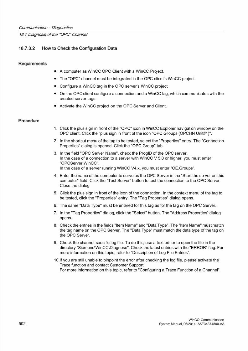
8/20/2019 WinCC Communication en-US en-US
http://slidepdf.com/reader/full/wincc-communication-en-us-en-us 502/527
18.7.3.2 How to Check the Configuration Data
Requirements
● A computer as WinCC OPC Client with a WinCC Project.
● The "OPC" channel must be integrated in the OPC client's WinCC project.
● Configure a WinCC tag in the OPC server's WinCC project.
● On the OPC client configure a connection and a WinCC tag, which communicates with thecreated server tags.
● Activate the WinCC project on the OPC Server and Client.
Procedure
1. Click the plus sign in front of the "OPC" icon in WinCC Explorer navigation window on theOPC client. Click the "plus sign in front of the icon "OPC Groups (OPCHN Unit#1)".
2. In the shortcut menu of the tag to be tested, select the "Properties" entry. The "ConnectionProperties" dialog is opened. Click the "OPC Group" tab.
3. In the field "OPC Server Name", check the ProgID of the OPC server.In the case of a connection to a server with WinCC V 5.0 or higher, you must enter"OPCServer.WinCC".In the case of a server running WinCC V4.x, you must enter "OE.Groups".
4. Enter the name of the computer to serve as the OPC Server in the "Start the server on thiscomputer" field. Click the "Test Server" button to test the connection to the OPC Server.
Close the dialog.
5. Click the plus sign in front of the icon of the connection. In the context menu of the tag tobe tested, click the "Properties" entry. The "Tag Properties" dialog opens.
6. The same "Data Type" must be entered for this tag as for the tag on the OPC Server.
7. In the "Tag Properties" dialog, click the "Select" button. The "Address Properties" dialogopens.
8. Check the entries in the fields "Item Name" and "Data Type". The "Item Name" must matchthe tag name on the OPC Server. The "Data Type" must match the data type of the tag onthe OPC Server.
9. Check the channel-specific log file. To do this, use a text editor to open the file in the
directory "Siemens\WinCC\Diagnose". Check the latest entries with the "ERROR" flag. Formore information on this topic, refer to "Description of Log File Entries".
10.If you are still unable to pinpoint the error after checking the log file, please activate theTrace function and contact Customer Support.For more information on this topic, refer to "Configuring a Trace Function of a Channel".
Communication - Diagnostics
18.7 Diagnosis of the "OPC" Channel
WinCC: Communication502 System Manual, 06/2014, A5E34374800-AA

8/20/2019 WinCC Communication en-US en-US
http://slidepdf.com/reader/full/wincc-communication-en-us-en-us 503/527
See also
How to Configure the Trace Function of a Channel (Page 471)
Description of Log File Entries (Page 498)
How to Check the Channel and the Connection (Page 503)
18.7.3.3 How to Check the Channel and the Connection
Introduction
This section describes how to check the "OPC" channel and its connection in Runtime.
Requirements
● A computer as WinCC OPC Client with a WinCC Project.
● The "OPC" channel must be integrated in the OPC client's WinCC project.
● Configure a WinCC tag in the OPC server's WinCC project.
● On the OPC client configure a connection and a WinCC tag, which communicates with thecreated server tags.
● Activate the WinCC project on the OPC Server and Client.
Overview of Status Messages
Icon Description
Channel / connection unconditionally ready
Channel / connection ready with some restrictions
Channel / no statement possible regarding connection status
Channel / connection failed
Communication - Diagnostics
18.7 Diagnosis of the "OPC" Channel
WinCC: CommunicationSystem Manual, 06/2014, A5E34374800-AA 503
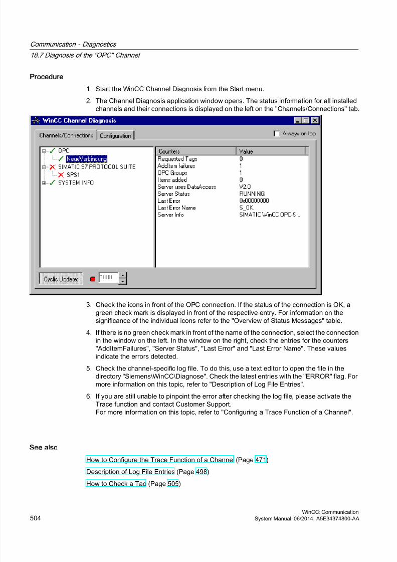
8/20/2019 WinCC Communication en-US en-US
http://slidepdf.com/reader/full/wincc-communication-en-us-en-us 504/527
Procedure
1. Start the WinCC Channel Diagnosis from the Start menu.
2. The Channel Diagnosis application window opens. The status information for all installedchannels and their connections is displayed on the left on the "Channels/Connections" tab.
3. Check the icons in front of the OPC connection. If the status of the connection is OK, agreen check mark is displayed in front of the respective entry. For information on thesignificance of the individual icons refer to the "Overview of Status Messages" table.
4. If there is no green check mark in front of the name of the connection, select the connectionin the window on the left. In the window on the right, check the entries for the counters"AddItemFailures", "Server Status", "Last Error" and "Last Error Name". These valuesindicate the errors detected.
5. Check the channel-specific log file. To do this, use a text editor to open the file in thedirectory "Siemens\WinCC\Diagnose". Check the latest entries with the "ERROR" flag. Formore information on this topic, refer to "Description of Log File Entries".
6. If you are still unable to pinpoint the error after checking the log file, please activate theTrace function and contact Customer Support.For more information on this topic, refer to "Configuring a Trace Function of a Channel".
See also
How to Configure the Trace Function of a Channel (Page 471)
Description of Log File Entries (Page 498)
How to Check a Tag (Page 505)
Communication - Diagnostics
18.7 Diagnosis of the "OPC" Channel
WinCC: Communication504 System Manual, 06/2014, A5E34374800-AA
8/20/2019 WinCC Communication en-US en-US
http://slidepdf.com/reader/full/wincc-communication-en-us-en-us 505/527
18.7.3.4 How to Check a Tag
Introduction
If an external tag does not have the expected value in Runtime, you can use the followingprocedure to check the tag.
Requirements
● A computer as WinCC OPC Client with a WinCC Project.
● The "OPC" channel must be integrated in the OPC client's WinCC project.
● Configure a WinCC tag in the OPC server's WinCC project.
● On the OPC client configure a connection and a WinCC tag, which communicates with thecreated server tags.
● Activate the WinCC project on the OPC Server and Client.
Procedure
1. In WinCC Explorer in tag management, select the "OPC" channel.
2. In the data window, select the external tag that you wish to check. To do this, open thedirectory structure until the tag is displayed in the table area.
3. Move the mouse pointer over the tag to be checked. A tooltip window opens with the currenttag value, the quality value and the time of the most recent change.
4. Check the quality value. If the value "C0" is displayed, the tag value is OK. A descriptionof the other values can be found under "Tag quality codes".
5. If the quality code is not equal to "C0", select the tag in tag management and click"Properties" in the shortcut menu to open the "Tag Properties" dialog.
6. Check whether values have been configured for the high or low limits, the start or substitutevalues on the "Limits/Reporting" tab. These values can affect the display.
7. If the tag value is affected by one of the configured values, deactivate the project andchange the limit or substitute value.
Note
Tag values, quality codes etc. are only displayed in Runtime.
See also
Quality Codes of Tags (Page 508)
Communication - Diagnostics
18.7 Diagnosis of the "OPC" Channel
WinCC: CommunicationSystem Manual, 06/2014, A5E34374800-AA 505
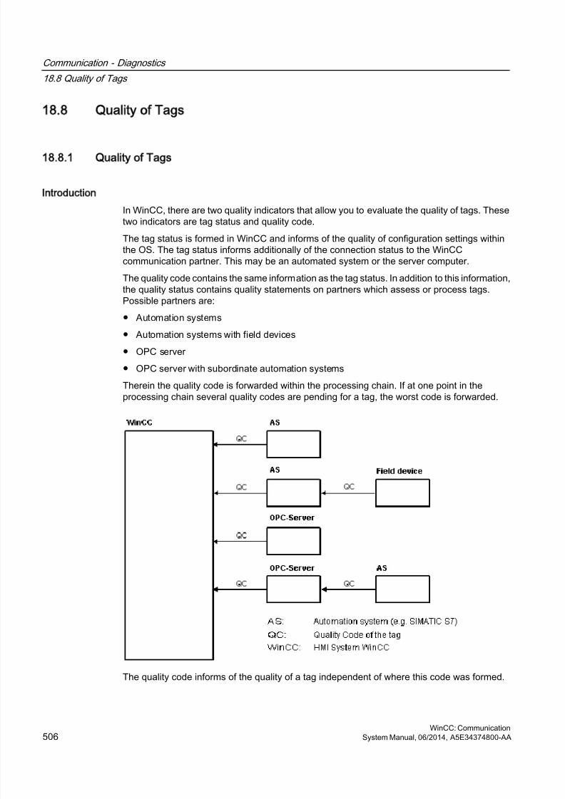
8/20/2019 WinCC Communication en-US en-US
http://slidepdf.com/reader/full/wincc-communication-en-us-en-us 506/527
18.8 Quality of Tags
18.8.1 Quality of Tags
Introduction
In WinCC, there are two quality indicators that allow you to evaluate the quality of tags. Thesetwo indicators are tag status and quality code.
The tag status is formed in WinCC and informs of the quality of configuration settings withinthe OS. The tag status informs additionally of the connection status to the WinCCcommunication partner. This may be an automated system or the server computer.
The quality code contains the same information as the tag status. In addition to this information,the quality status contains quality statements on partners which assess or process tags.Possible partners are:
● Automation systems
● Automation systems with field devices
● OPC server
● OPC server with subordinate automation systems
Therein the quality code is forwarded within the processing chain. If at one point in theprocessing chain several quality codes are pending for a tag, the worst code is forwarded.
The quality code informs of the quality of a tag independent of where this code was formed.
Communication - Diagnostics
18.8 Quality of Tags
WinCC: Communication506 System Manual, 06/2014, A5E34374800-AA
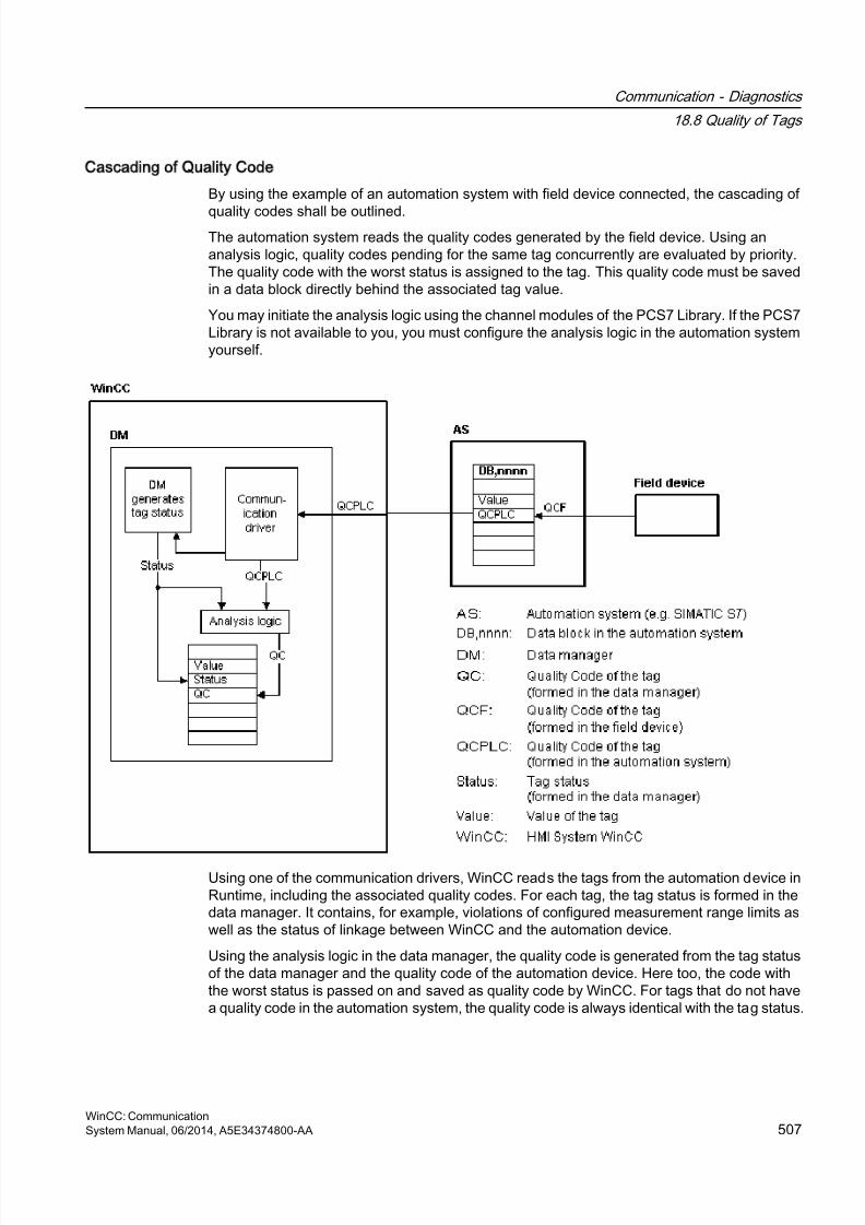
8/20/2019 WinCC Communication en-US en-US
http://slidepdf.com/reader/full/wincc-communication-en-us-en-us 507/527
Cascading of Quality Code
By using the example of an automation system with field device connected, the cascading of
quality codes shall be outlined.The automation system reads the quality codes generated by the field device. Using ananalysis logic, quality codes pending for the same tag concurrently are evaluated by priority.The quality code with the worst status is assigned to the tag. This quality code must be savedin a data block directly behind the associated tag value.
You may initiate the analysis logic using the channel modules of the PCS7 Library. If the PCS7Library is not available to you, you must configure the analysis logic in the automation systemyourself.
Using one of the communication drivers, WinCC reads the tags from the automation device inRuntime, including the associated quality codes. For each tag, the tag status is formed in thedata manager. It contains, for example, violations of configured measurement range limits aswell as the status of linkage between WinCC and the automation device.
Using the analysis logic in the data manager, the quality code is generated from the tag statusof the data manager and the quality code of the automation device. Here too, the code withthe worst status is passed on and saved as quality code by WinCC. For tags that do not havea quality code in the automation system, the quality code is always identical with the tag status.
Communication - Diagnostics
18.8 Quality of Tags
WinCC: CommunicationSystem Manual, 06/2014, A5E34374800-AA 507

8/20/2019 WinCC Communication en-US en-US
http://slidepdf.com/reader/full/wincc-communication-en-us-en-us 508/527
18.8.2 Quality Codes of Tags
Introduction
The quality code is needed to check status and quality of a tag. The displayed quality codesummarizes the quality of the entire value transmission and value processing for the respectivetag. Thus with the quality code you can for example see whether the current value is a startvalue or a substitute value.
The quality codes are prioritized. If several codes occur at the same time, the code with theworst status is displayed.
Evaluation of Quality Codes
Quality codes can be evaluated in a number of different ways:● Evaluation with VB scripts
● Evaluation with C scripts
● Evaluation through the dynamic dialog
● Evaluation of the "Quality Code Change Tag" result of an I/O field
Note
In order to include the entire value transfer and value processing in the quality code for aprocess tag, the connected automation system must support the quality code. Whenconfiguring the tags in the AS, make sure there is enough memory space for the quality code.In an AS from the S7 family, for example, the quality code needs an additional byte that isappended to the process value. To prevent errors, this byte must be taken into account whenconfiguring a tag, for instance at the end of a data block.
Display of Quality Codes in Tag Management
You can view the quality code of a tag in Tag Management.
Requirements:
● The WinCC project is activated.
● The "Quality Code" column in the Tag Management data area is displayed.
Communication - Diagnostics
18.8 Quality of Tags
WinCC: Communication508 System Manual, 06/2014, A5E34374800-AA
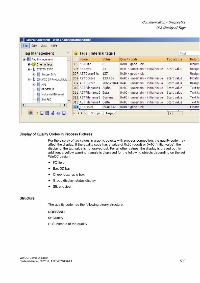
8/20/2019 WinCC Communication en-US en-US
http://slidepdf.com/reader/full/wincc-communication-en-us-en-us 509/527
Display of Quality Codes in Process Pictures
For the display of tag values in graphic objects with process connection, the quality code mayaffect the display. If the quality code has a value of 0x80 (good) or 0x4C (initial value), the
display of the tag value is not grayed out. For all other values, the display is grayed out. Inaddition, a yellow warning triangle is displayed for the following objects depending on the setWinCC design:
● I/O field
● Bar, 3D bar
● Check box, radio box
● Group display, status display
● Slider object
Structure
The quality code has the following binary structure:
QQSSSSLL
Q: Quality
S: Substatus of the quality
Communication - Diagnostics
18.8 Quality of Tags
WinCC: CommunicationSystem Manual, 06/2014, A5E34374800-AA 509
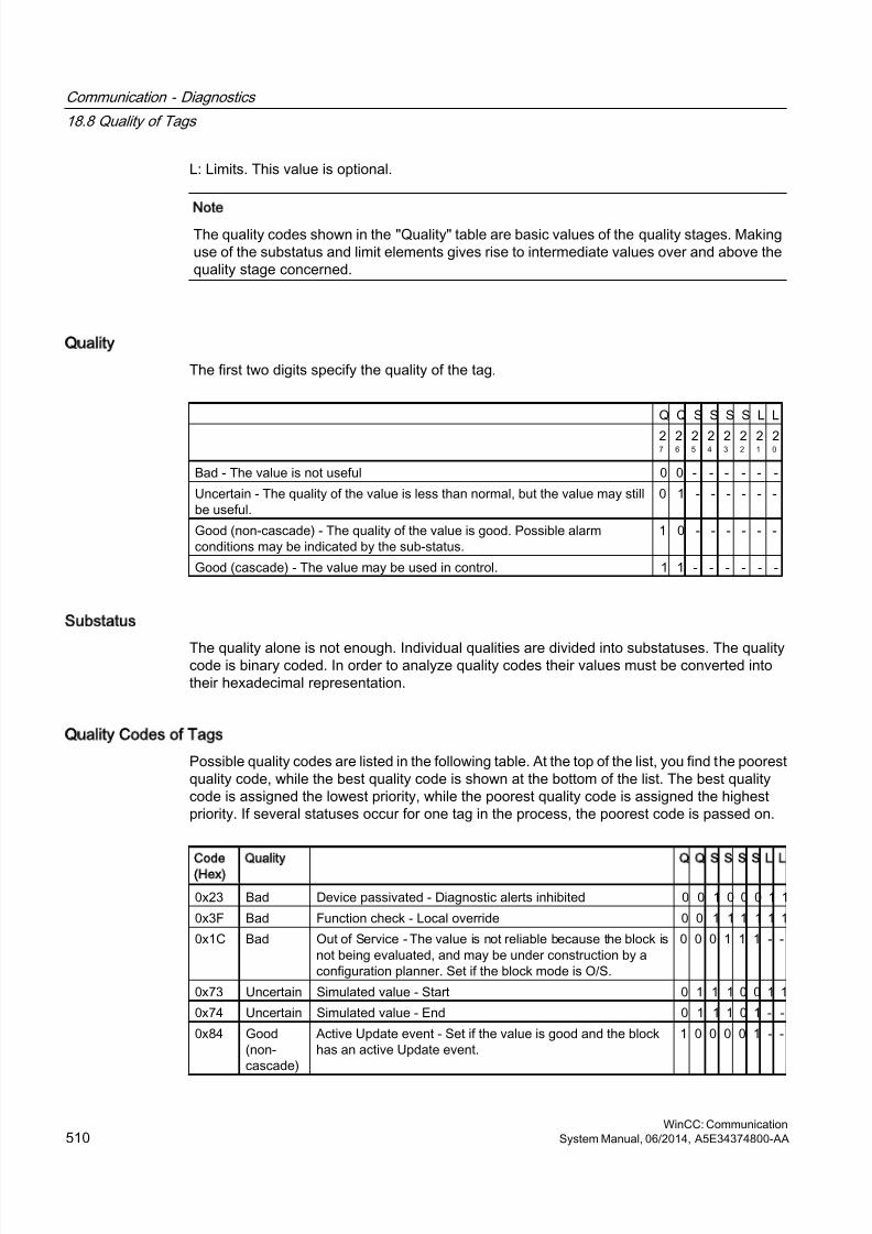
8/20/2019 WinCC Communication en-US en-US
http://slidepdf.com/reader/full/wincc-communication-en-us-en-us 510/527
L: Limits. This value is optional.
Note
The quality codes shown in the "Quality" table are basic values of the quality stages. Makinguse of the substatus and limit elements gives rise to intermediate values over and above thequality stage concerned.
Quality
The first two digits specify the quality of the tag.
Q Q S S S S L L
27
26
25
24
23
22
21
20
Bad - The value is not useful 0 0 - - - - - -
Uncertain - The quality of the value is less than normal, but the value may stillbe useful.
0 1 - - - - - -
Good (non-cascade) - The quality of the value is good. Possible alarmconditions may be indicated by the sub-status.
1 0 - - - - - -
Good (cascade) - The value may be used in control. 1 1 - - - - - -
Substatus
The quality alone is not enough. Individual qualities are divided into substatuses. The qualitycode is binary coded. In order to analyze quality codes their values must be converted intotheir hexadecimal representation.
Quality Codes of Tags
Possible quality codes are listed in the following table. At the top of the list, you find the poorestquality code, while the best quality code is shown at the bottom of the list. The best qualitycode is assigned the lowest priority, while the poorest quality code is assigned the highestpriority. If several statuses occur for one tag in the process, the poorest code is passed on.
Code
(Hex)
Quality Q Q S S S S L L
0x23 Bad Device passivated - Diagnostic alerts inhibited 0 0 1 0 0 0 1 1
0x3F Bad Function check - Local override 0 0 1 1 1 1 1 1
0x1C Bad Out of Service - The value is not reliable because the block isnot being evaluated, and may be under construction by aconfiguration planner. Set if the block mode is O/S.
0 0 0 1 1 1 - -
0x73 Uncertain Simulated value - Start 0 1 1 1 0 0 1 1
0x74 Uncertain Simulated value - End 0 1 1 1 0 1 - -
0x84 Good(non-cascade)
Active Update event - Set if the value is good and the blockhas an active Update event.
1 0 0 0 0 1 - -
Communication - Diagnostics
18.8 Quality of Tags
WinCC: Communication510 System Manual, 06/2014, A5E34374800-AA
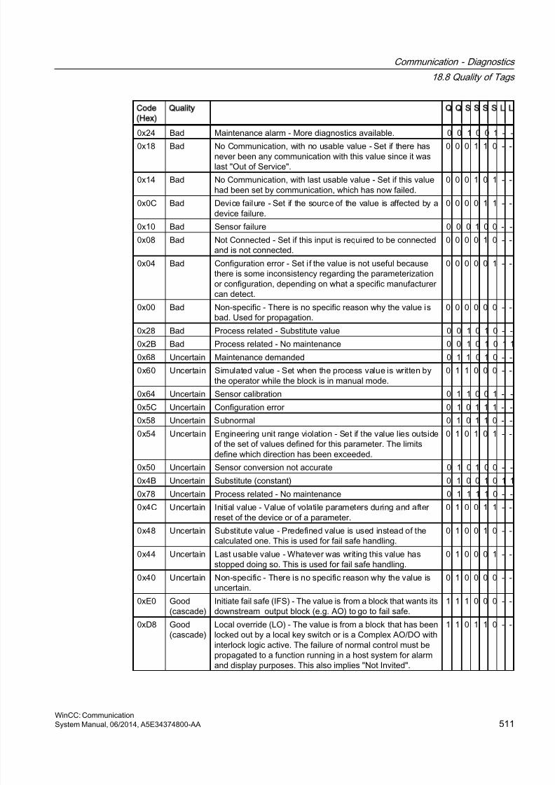
8/20/2019 WinCC Communication en-US en-US
http://slidepdf.com/reader/full/wincc-communication-en-us-en-us 511/527
Code
(Hex)
Quality Q Q S S S S L L
0x24 Bad Maintenance alarm - More diagnostics available. 0 0 1 0 0 1 - -0x18 Bad No Communication, with no usable value - Set if there hasnever been any communication with this value since it waslast "Out of Service".
0 0 0 1 1 0 - -
0x14 Bad No Communication, with last usable value - Set if this valuehad been set by communication, which has now failed.
0 0 0 1 0 1 - -
0x0C Bad Device failure - Set if the source of the value is affected by adevice failure.
0 0 0 0 1 1 - -
0x10 Bad Sensor failure 0 0 0 1 0 0 - -
0x08 Bad Not Connected - Set if this input is required to be connectedand is not connected.
0 0 0 0 1 0 - -
0x04 Bad Configuration error - Set i f the value is not useful because
there is some inconsistency regarding the parameterizationor configuration, depending on what a specific manufacturercan detect.
0 0 0 0 0 1 - -
0x00 Bad Non-specific - There is no specific reason why the value isbad. Used for propagation.
0 0 0 0 0 0 - -
0x28 Bad Process related - Substitute value 0 0 1 0 1 0 - -
0x2B Bad Process related - No maintenance 0 0 1 0 1 0 1 1
0x68 Uncertain Maintenance demanded 0 1 1 0 1 0 - -
0x60 Uncertain Simulated value - Set when the process value is written bythe operator while the block is in manual mode.
0 1 1 0 0 0 - -
0x64 Uncertain Sensor calibration 0 1 1 0 0 1 - -
0x5C Uncertain Configuration error 0 1 0 1 1 1 - -
0x58 Uncertain Subnormal 0 1 0 1 1 0 - -
0x54 Uncertain Engineering unit range violation - Set if the value lies outsideof the set of values defined for this parameter. The limitsdefine which direction has been exceeded.
0 1 0 1 0 1 - -
0x50 Uncertain Sensor conversion not accurate 0 1 0 1 0 0 - -
0x4B Uncertain Substitute (constant) 0 1 0 0 1 0 1 1
0x78 Uncertain Process related - No maintenance 0 1 1 1 1 0 - -
0x4C Uncertain Initial value - Value of volatile parameters during and afterreset of the device or of a parameter.
0 1 0 0 1 1 - -
0x48 Uncertain Substitute value - Predefined value is used instead of thecalculated one. This is used for fail safe handling.
0 1 0 0 1 0 - -
0x44 Uncertain Last usable value - Whatever was writing this value hasstopped doing so. This is used for fail safe handling.
0 1 0 0 0 1 - -
0x40 Uncertain Non-specific - There is no specific reason why the value isuncertain.
0 1 0 0 0 0 - -
0xE0 Good(cascade)
Initiate fail safe (IFS) - The value is from a block that wants itsdownstream output block (e.g. AO) to go to fail safe.
1 1 1 0 0 0 - -
0xD8 Good(cascade)
Local override (LO) - The value is from a block that has beenlocked out by a local key switch or is a Complex AO/DO withinterlock logic active. The failure of normal control must bepropagated to a function running in a host system for alarmand display purposes. This also implies "Not Invited".
1 1 0 1 1 0 - -
Communication - Diagnostics
18.8 Quality of Tags
WinCC: CommunicationSystem Manual, 06/2014, A5E34374800-AA 511
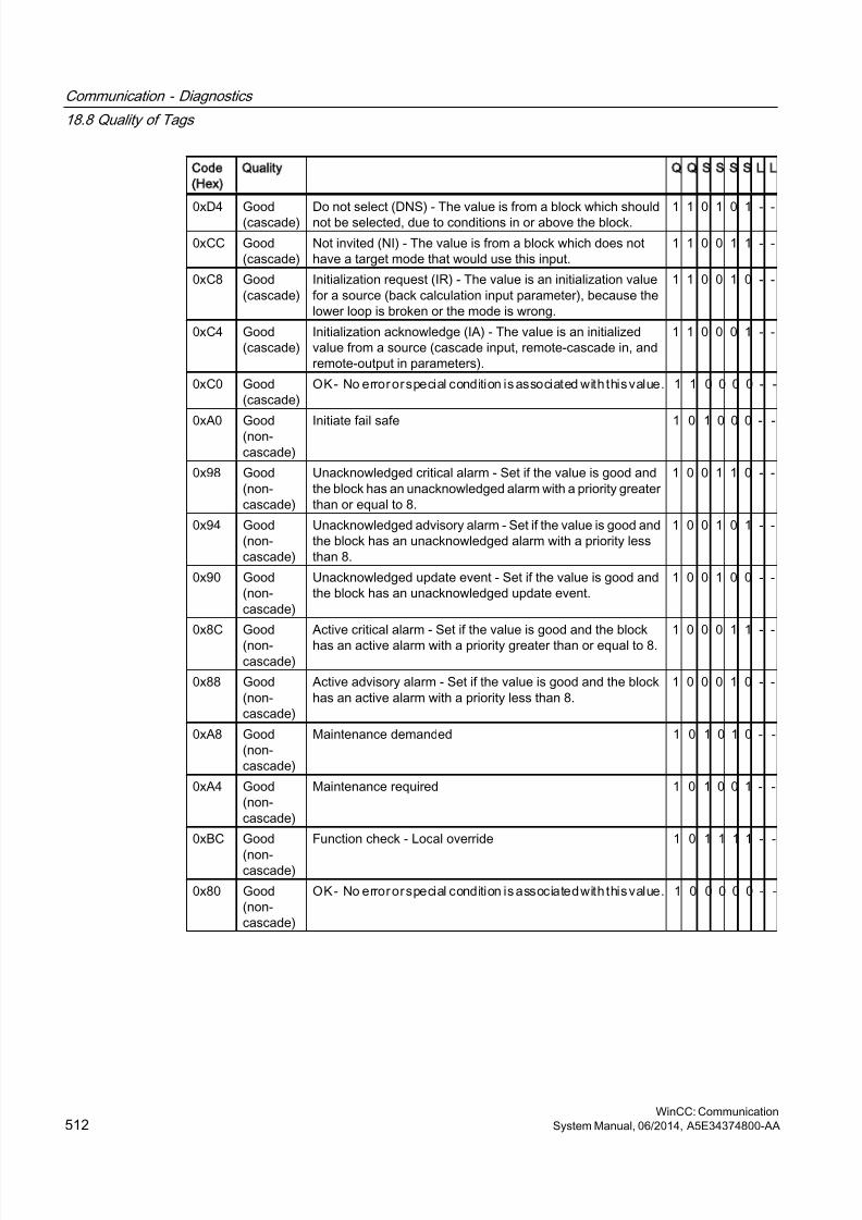
8/20/2019 WinCC Communication en-US en-US
http://slidepdf.com/reader/full/wincc-communication-en-us-en-us 512/527
Code
(Hex)
Quality Q Q S S S S L L
0xD4 Good(cascade) Do not select (DNS) - The value is from a block which shouldnot be selected, due to conditions in or above the block. 1 1 0 1 0 1 - -
0xCC Good(cascade)
Not invited (NI) - The value is from a block which does nothave a target mode that would use this input.
1 1 0 0 1 1 - -
0xC8 Good(cascade)
Initialization request (IR) - The value is an initialization valuefor a source (back calculation input parameter), because thelower loop is broken or the mode is wrong.
1 1 0 0 1 0 - -
0xC4 Good(cascade)
Initialization acknowledge (IA) - The value is an initializedvalue from a source (cascade input, remote-cascade in, andremote-output in parameters).
1 1 0 0 0 1 - -
0xC0 Good(cascade)
OK - No error or special condition is associated with this value. 1 1 0 0 0 0 - -
0xA0 Good(non-cascade)
Initiate fail safe 1 0 1 0 0 0 - -
0x98 Good(non-cascade)
Unacknowledged critical alarm - Set if the value is good andthe block has an unacknowledged alarm with a priority greaterthan or equal to 8.
1 0 0 1 1 0 - -
0x94 Good(non-cascade)
Unacknowledged advisory alarm - Set if the value is good andthe block has an unacknowledged alarm with a priority lessthan 8.
1 0 0 1 0 1 - -
0x90 Good(non-cascade)
Unacknowledged update event - Set if the value is good andthe block has an unacknowledged update event.
1 0 0 1 0 0 - -
0x8C Good
(non-cascade)
Active critical alarm - Set if the value is good and the block
has an active alarm with a priority greater than or equal to 8.
1 0 0 0 1 1 - -
0x88 Good(non-cascade)
Active advisory alarm - Set if the value is good and the blockhas an active alarm with a priority less than 8.
1 0 0 0 1 0 - -
0xA8 Good(non-cascade)
Maintenance demanded 1 0 1 0 1 0 - -
0xA4 Good(non-cascade)
Maintenance required 1 0 1 0 0 1 - -
0xBC Good
(non-cascade)
Function check - Local override 1 0 1 1 1 1 - -
0x80 Good(non-cascade)
OK - No error or special condition is associated with this value. 1 0 0 0 0 0 - -
Communication - Diagnostics
18.8 Quality of Tags
WinCC: Communication512 System Manual, 06/2014, A5E34374800-AA
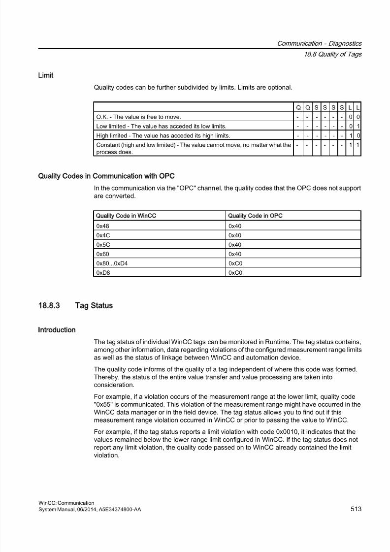
8/20/2019 WinCC Communication en-US en-US
http://slidepdf.com/reader/full/wincc-communication-en-us-en-us 513/527
Limit
Quality codes can be further subdivided by limits. Limits are optional.
Q Q S S S S L L
O.K. - The value is free to move. - - - - - - 0 0
Low limited - The value has acceded its low limits. - - - - - - 0 1
High limited - The value has acceded its high limits. - - - - - - 1 0
Constant (high and low limited) - The value cannot move, no matter what theprocess does.
- - - - - - 1 1
Quality Codes in Communication with OPC
In the communication via the "OPC" channel, the quality codes that the OPC does not support
are converted.
Quality Code in WinCC Quality Code in OPC
0x48 0x40
0x4C 0x40
0x5C 0x40
0x60 0x40
0x80...0xD4 0xC0
0xD8 0xC0
18.8.3 Tag Status
Introduction
The tag status of individual WinCC tags can be monitored in Runtime. The tag status contains,among other information, data regarding violations of the configured measurement range limitsas well as the status of linkage between WinCC and automation device.
The quality code informs of the quality of a tag independent of where this code was formed.Thereby, the status of the entire value transfer and value processing are taken into
consideration.For example, if a violation occurs of the measurement range at the lower limit, quality code"0x55" is communicated. This violation of the measurement range might have occurred in theWinCC data manager or in the field device. The tag status allows you to find out if thismeasurement range violation occurred in WinCC or prior to passing the value to WinCC.
For example, if the tag status reports a limit violation with code 0x0010, it indicates that thevalues remained below the lower range limit configured in WinCC. If the tag status does notreport any limit violation, the quality code passed on to WinCC already contained the limitviolation.
Communication - Diagnostics
18.8 Quality of Tags
WinCC: CommunicationSystem Manual, 06/2014, A5E34374800-AA 513
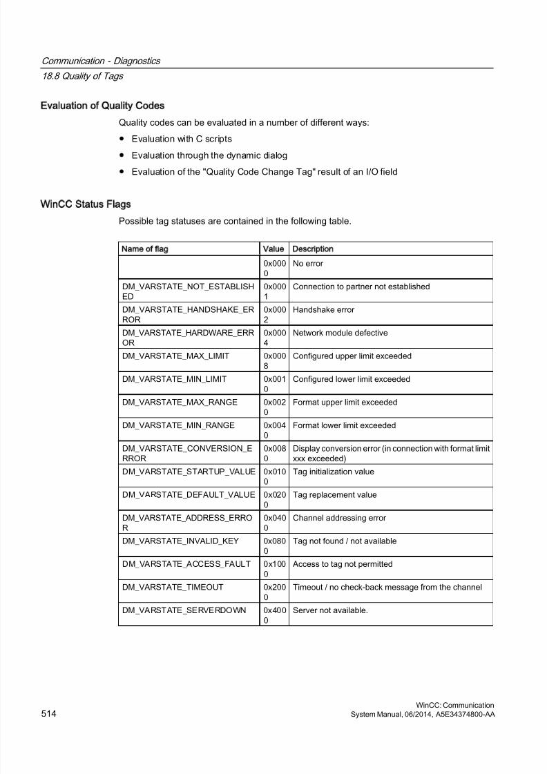
8/20/2019 WinCC Communication en-US en-US
http://slidepdf.com/reader/full/wincc-communication-en-us-en-us 514/527
Evaluation of Quality Codes
Quality codes can be evaluated in a number of different ways:
● Evaluation with C scripts
● Evaluation through the dynamic dialog
● Evaluation of the "Quality Code Change Tag" result of an I/O field
WinCC Status Flags
Possible tag statuses are contained in the following table.
Name of flag Value Description
0x000
0
No error
DM_VARSTATE_NOT_ESTABLISHED
0x0001
Connection to partner not established
DM_VARSTATE_HANDSHAKE_ERROR
0x0002
Handshake error
DM_VARSTATE_HARDWARE_ERROR
0x0004
Network module defective
DM_VARSTATE_MAX_LIMIT 0x0008
Configured upper limit exceeded
DM_VARSTATE_MIN_LIMIT 0x0010
Configured lower limit exceeded
DM_VARSTATE_MAX_RANGE 0x0020
Format upper limit exceeded
DM_VARSTATE_MIN_RANGE 0x0040
Format lower limit exceeded
DM_VARSTATE_CONVERSION_ERROR
0x0080
Display conversion error (in connection with format limitxxx exceeded)
DM_VARSTATE_STARTUP_VALUE 0x0100
Tag initialization value
DM_VARSTATE_DEFAULT_VALUE 0x0200
Tag replacement value
DM_VARSTATE_ADDRESS_ERROR
0x0400
Channel addressing error
DM_VARSTATE_INVALID_KEY 0x0800 Tag not found / not available
DM_VARSTATE_ACCESS_FAULT 0x1000
Access to tag not permitted
DM_VARSTATE_TIMEOUT 0x2000
Timeout / no check-back message from the channel
DM_VARSTATE_SERVERDOWN 0x4000
Server not available.
Communication - Diagnostics
18.8 Quality of Tags
WinCC: Communication514 System Manual, 06/2014, A5E34374800-AA
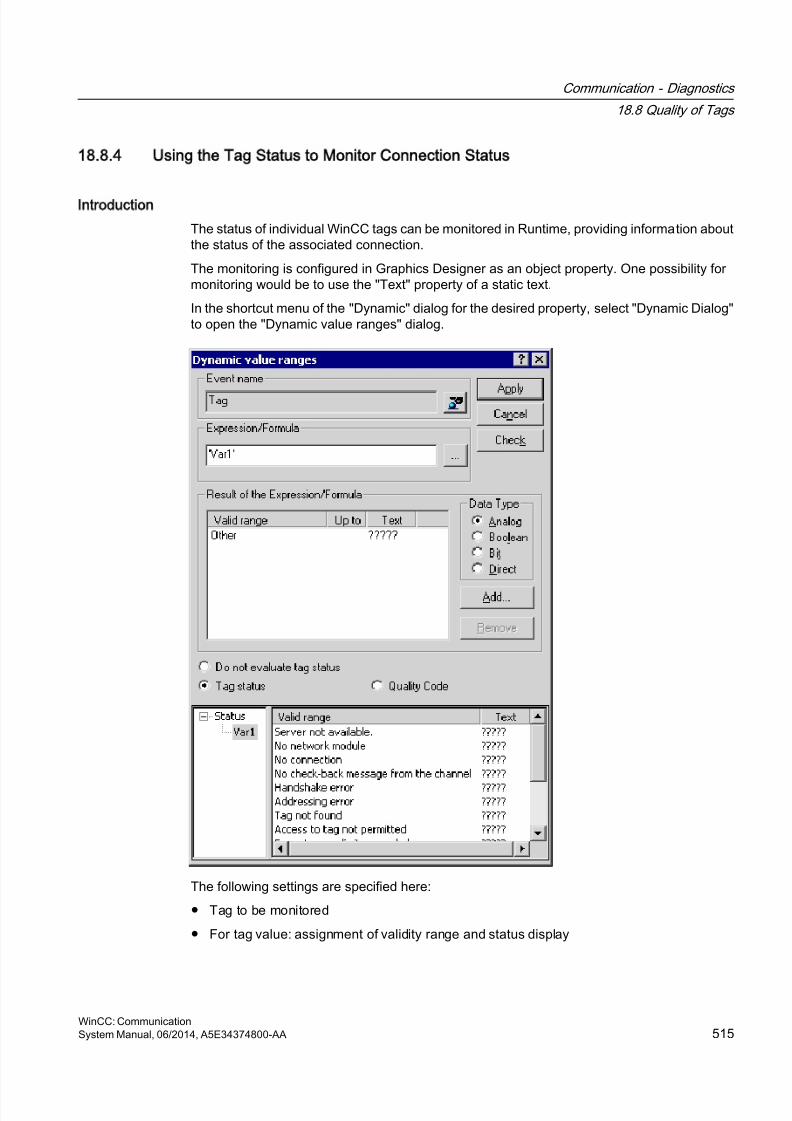
8/20/2019 WinCC Communication en-US en-US
http://slidepdf.com/reader/full/wincc-communication-en-us-en-us 515/527
18.8.4 Using the Tag Status to Monitor Connection Status
Introduction
The status of individual WinCC tags can be monitored in Runtime, providing information aboutthe status of the associated connection.
The monitoring is configured in Graphics Designer as an object property. One possibility formonitoring would be to use the "Text" property of a static text.
In the shortcut menu of the "Dynamic" dialog for the desired property, select "Dynamic Dialog"to open the "Dynamic value ranges" dialog.
The following settings are specified here:
● Tag to be monitored
● For tag value: assignment of validity range and status display
Communication - Diagnostics
18.8 Quality of Tags
WinCC: CommunicationSystem Manual, 06/2014, A5E34374800-AA 515
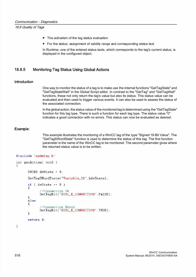
8/20/2019 WinCC Communication en-US en-US
http://slidepdf.com/reader/full/wincc-communication-en-us-en-us 516/527
● The activation of the tag status evaluation
● For the status: assignment of validity range and corresponding status text
In Runtime, one of the entered status texts, which corresponds to the tag's current status, isdisplayed in the configured object.
18.8.5 Monitoring Tag Status Using Global Actions
Introduction
One way to monitor the status of a tag is to make use the internal functions "GetTagState" and"GetTagStateWait" in the Global Script editor. In contrast to the "GetTag" and "GetTagWait"
functions, these not only return the tag's value but also its status. This status value can beevaluated and then used to trigger various events. It can also be used to assess the status ofthe associated connection.
In the global action, the status value of the monitored tag is determined using the "GetTagState"function for this tag type. There is such a function for each tag type. The status value "0"indicates a good connection with no errors. This status can now be evaluated as desired.
Example:
This example illustrates the monitoring of a WinCC tag of the type "Signed 16-Bit Value". The"GetTagSWordState" function is used to determine the status of this tag. The first functionparameter is the name of the WinCC tag to be monitored. The second parameter gives where
the returned status value is to be written.
Communication - Diagnostics
18.8 Quality of Tags
WinCC: Communication516 System Manual, 06/2014, A5E34374800-AA
8/20/2019 WinCC Communication en-US en-US
http://slidepdf.com/reader/full/wincc-communication-en-us-en-us 517/527
The tag status is output in the internal tag BINi_E_CONNECTION. In the event of an error, thevalue of this tag is set to TRUE. In the error handling, the tag can, for example, be used totrigger an alarm or display an error message.
18.8.6 How to Check an Internal Tag
Introduction
If an internal tag does not have the expected value in Runtime, you can use the followingprocedure to check the tag.
Requirements
● An internal tag has been configured.
● The WinCC project is activated.
Procedure
1. Open Tag Management in the WinCC Explorer.
2. Select the entry "Internal tags" and the tag to be checked in the navigation area.
3. To display the "Quality Code" and "Value" columns in the data area, you may have to goto "Show" and select these columns in the shortcut menu of a column header.
4. Check the quality code. If the value "80" is displayed, the tag value is OK. A description ofthe other values can be found under "Tag Quality Codes".
5. If the quality code is not equal to "80", check the settings under properties on the right.
6. Check whether values have been configured for the upper and lower limits or start value.These values can affect the display.
7. If the tag value is affected by one of the configured values, deactivate the project andchange the limit or substitute value.
Communication - Diagnostics
18.8 Quality of Tags
WinCC: CommunicationSystem Manual, 06/2014, A5E34374800-AA 517
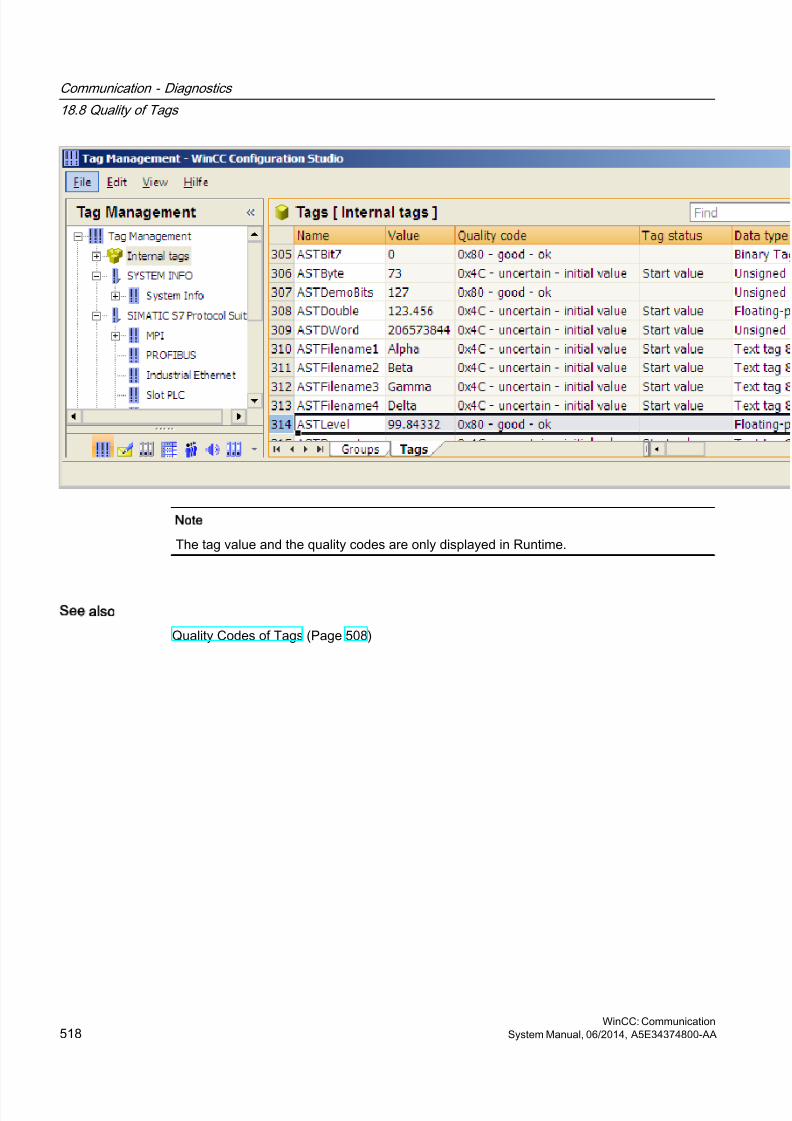
8/20/2019 WinCC Communication en-US en-US
http://slidepdf.com/reader/full/wincc-communication-en-us-en-us 518/527
Note
The tag value and the quality codes are only displayed in Runtime.
See also
Quality Codes of Tags (Page 508)
Communication - Diagnostics
18.8 Quality of Tags
WinCC: Communication518 System Manual, 06/2014, A5E34374800-AA

8/20/2019 WinCC Communication en-US en-US
http://slidepdf.com/reader/full/wincc-communication-en-us-en-us 519/527
Index
A&E server Mapping WinCC message classes and messagetypes, 186
as ActiveX Control, 468 Connecting WinCC - OPC A&E client
Example of OPC A&E , 178 OPC A&E server , 173, 186 Testing, 465
"MPI" channel unit, 312Configuring the connection, 312
"Slot PLC" channel unit, 319Configuring the connection, 319
"System Info" channel, 473Diagnostic option, 473
5
505-Ethernet (CP 1413-x)Channel Unit, 397
A
A&E server, 171, 172, 181, 183, 186Condition Related Event, 171Conditional event, 181Mapping the WinCC message system, 186Simple event, 181Tracking event, 171, 181
A&E Server
Hierarchical access, 183Mapping of the WinCC message system, 172
Acknowledgement theory, 176Acknowledgment policy, 189Adding a tag, 81, 89
Example of OPC DA, 138Adding new drivers, 258Address properties, 93, 108, 261, 262, 263, 267
Example for S5 Profibus FDL, 276Address type
Mitsubishi Ethernet, 64Addresses of tags, 401
TI Ethernet Layer 4, 401AR_SENDAR_SEND-FunctioninWinCC , 337AR_SEND-Function in WinCC
Configuring Variants for an Archive Tag, 364Configuring Variants for Multiple Archive Tags,367Data Block,Structure and Parameters, 338Example for Data Block Structure, 347, 348, 349,354, 356, 358, 360, 363Overview of the properties of the variants, 343Variants for an Archive Tag, 345Variants for Multiple Archive Tags, 350
Variants for Multiple Archive Tags (optimized),362AS data type, 17
Type conversion, 27AS511, 279Automation device, 256
B
Bar Example of System Info, 446
BinWrite Mechanism, 35
General Procedure, 35Bit by bit access, 35, 237, 325S5 AS511, 286S5 Ethernet Layer 4, 237S5 Profibus FDL, 261S5 Serial 3964R, 295S7 Protocol Suite, 325TI Ethernet Layer 4, 403TI Serial, 414
Bit/Byte access, 35Bit-/Byte-tag, 37Block, 273
Cyclic block, 273Bounding values, 155Buffer time, 179Byte array, 267Byte by byte access, 35, 238, 325
S5 AS511, 287S5 Ethernet Layer 4, 238S5 Profibus FDL, 262S5 Serial 3964R, 297S7 Protocol Suite, 327TI Ethernet Layer 4, 404TI Serial, 415
WinCC: CommunicationSystem Manual, 06/2014, A5E34374800-AA 519
8/20/2019 WinCC Communication en-US en-US
http://slidepdf.com/reader/full/wincc-communication-en-us-en-us 520/527
C
Channel, 15, 231, 289, 300, 503check, 474, 485, 495Configuring SIMATIC S5 PROFIBUS FDL, 258Diagnosis of channels, 465Example for S5 PROFIBUS FDL, 273Mitsubishi Ethernet, (See Mitsubishi Ethernet)PROFIBUS FMS, 221SIMATIC S5 Ethernet Layer 4, 231SIMATIC S5 Programmers Port AS511, 279SIMATIC S5 Serial 3964R, 289SIMATIC S7 Protocol Suite, 300SIMATIC TI Ethernet Layer 4, 397Status - Logical Connections function , 465Testing, 503TI Serial, 409
Channel , 221Channel diagnosis, 467
"System Info" channel, 473Chanel with , 468, 470Channel diagnosis, 467, 468, 469Channel diagnosis as Windows application , 469Channel diagnosis with , 468Channel diagonsis, 465Channel with Status - Logical Connections
function , 465Checking configuration data, 502Checking connection, 503Checking internal tags, 517Checking the configuration of the communicationprocessor, 481, 483, 491, 492Configuring a the Trace function of a channel,471Connection parameters, 493Diagnostic option, 473, 478, 489, 498ERROR flag of logbook entry, 473, 478Example, 516
Function , 465INFO flag of logbook entry, 473, 478, 489, 498Log file, 473, 478, 489, 498Monitoring of tag status in dynamic dialog, 515Monitoring of tag status with global actions, 516OPC channel, 498Overview of status messages, 503PROFIBUS system parameters, 484Properties - CP5613, 481, 483, 491, 492SIMATIC S5 PROFIBUS FDL channel, 489SIMATIC S7 Protocol Suite channel, 478Standard flags of the Trace function, 471Status - Logical Connections, 465
System parameters, 493Testing channel, 503WinCC channel diagnosis, 503
Channel DiagnosisChannel diagnosis with , 467Checking connection, 474, 485, 495Overview of status messages, 474, 485, 495Testing channel, 474, 485, 495WinCC channel diagnosis, 474, 485, 495
Channel diagnosis channel Testing, 468, 470
Channel diagnosis Channel DiagnoseChannel diagnosis Channel Diagnose , 469Channel diagnosis with Channel Diagnose , 468
Channel Diagnosis trace file , 467
Channel diagnosticsChecking tag, 476, 487, 497, 505
Channel unitConnection parameters, 399S5 Transport (CP1413-x), 233S5 Transport (TCP/IP), 233S5-AS511, 281
Channel Unit, 15, 231, 258, 302505 Serial Unit #1, 409505-Ethernet (CP 1413-x), 397FDL (CP5412/A2-1), 258Industrial Ethernet, 309MPI, 312Named Connections, 314PROFIBUS, 317PROFIBUS-FMS, 223S5-AS511, 279S5-RK512 (3964R), 289Selection for SIMATICS7ProtocolSuiteS7Protocol Suite channel:Selecting the channel unit,302Slot PLC, 319Soft PLC, 321System parameters, 242, 264, 331, 405, 406TCP/IP, 322
Channel unit FDL (CP5412/A2-1), 253, 258Channel Unit Industrial Ethernet, 309
Configuring the connection, 310Channel units
Mitsubishi Ethernet, (See Mitsubishi Ethernet)Commissioning, 220Communication, 13
Addressing in the automation system, 17AS data type, 20, 27Basis, 13BinWrite Mechanism, 35Bit-/Byte-access, 35
Index
WinCC: Communication520 System Manual, 06/2014, A5E34374800-AA
8/20/2019 WinCC Communication en-US en-US
http://slidepdf.com/reader/full/wincc-communication-en-us-en-us 521/527
Bit-/Byte-tag, 37Channel Unit, 15Communication between WinCC and Automation
systems, 15Communication driver, 15Configuring a tag with BinWrite, 37Configuring powertags, 20Connection, 15Connection properties, 19Creating a new connection, 19Data type, 17, 27Length definition for text tags, 17Linear scaling of numerical tag types, 17PowerTag, 17Principle of the BinWrite-Mechanism, 35
Principle of WinCC communication, 15Sorting format adaptation by AS data type, 27Sorting format adaptation by WinCC data type,21Tag Properties, 20Type conversion, 27Type Conversion, 17Value range, 27WinCC data types, 17WinCC process communication, 15WinCC Type Conversion, 17
Communication driver, 15, (See channel)Communication processor, 481, 483, 491, 492
Checking the configuration of the communicationprocessor, 481, 483, 491, 492
Communication type, 268Configuring, 268
Compatibility, 125Configuration data, 502Configuration file
File location, 216Layout, 216Port number, 216Security settings, 216URL of the WinCC OPC UA server, 216
User identification, 216WinCC archive write access, 216
Configure bit by bit accessTag, 403
Configure byte by byte accessTag, 404
configuringOptimized WinCC archive write access, 219Port number, 218Security settings, 218User identification, 219WinCC OPC UA Server, 217
ConfiguringTag, 401TI Ethernet Layer 4, 399
Configuring a tagTI Ethernet Layer 4, 401
Configuring a tag with bit by bit accessTI Ethernet Layer 4, 403
Configuring a tag with byte by byte accessTI Ethernet Layer 4, 404
Connecting WinCC - OPC A&E client, 178Connection, 15, 308, 503
Active connection, 253check, 474, 485, 495Configuring, 259, 310, 312, 315, 317, 319, 321,323
Creating a connection, 81Creating a new connection, 19Passive connection, 253Testing, 503Testing configuration of connection, 484, 493
Connection Monitoring, 86Connection parameters, 15, 233, 258, 259, 269, 271,308, 493
Channel unit, 399PROFIBUS FMS, 221S5 AS511, 279, 281S5 Ethernet Layer 4, 231S7 Protocol Suite, 300SIMATIC S5 Serial 3964R, 289TI Ethernet Layer 4, 397, 399TI Serial, 409
Connection properties, 19, 259, 269, 271Counter, 436CP1434 TF, 406, 407CPU load, 436
Example of System Info, 447Cyclic Read Services, 332
D
Data area, 255Data transmission, 268
Configuring a passive data transfer, 271Configuring an active data transfer, 269
Data type, 17, 85, 306, 390, 436Data types used, 436, 443Mitsubishi Ethernet, 60, 64S5 AS511, 280S5 Profibus FDL, 255S5 Serial 3964R, 290S7 Protocol Suite, 306SIMATIC S7-1200, S7-1500 Channel, 390
Index
WinCC: CommunicationSystem Manual, 06/2014, A5E34374800-AA 521
8/20/2019 WinCC Communication en-US en-US
http://slidepdf.com/reader/full/wincc-communication-en-us-en-us 522/527
Supported WinCC data types, 85Supported WinCC data types overview, 85TI Ethernet Layer 4, 398
Type conversion, 27Data Types, 17, 232
PROFIBUS FMS, 221, 222S5 Ethernet Layer 4, 232TI Ethernet Layer 4, 398
Date, 436Daylight Saving/Standard Time, 338Defining new tag, 145
Example of OPC DA, 145Device Name, 242, 264, 405
change, 265TI Ethernet Layer 4, 405
DiagnosisChannels, 429
Diagnostic option, 473, 478, 489, 498"System Info" channel, 473OPC channel, 498SIMATIC S5 PROFIBUS FDL channel, 489SIMATIC S7 Protocol Suite channel, 478
Disk capacity, 436Example of System Info, 446Free dive capacity, 436, 441
E
ERROR flag, 473, 478E-server
Functionality of WinCC OPC A&OPC, 129Example:, 516
F
Filter criteria, 89Functionality of the OPC A&E server
Conditional event, 181Simple event, 181
Tracking event, 181Functionality of the WinCC OPC A&E server
Simple event, 171
I
I/O fieldExample for S5 Profibus FDL, 276Example of System Info, 444
I/O field configuration, 138Example of OPC DA, 138
INFO flag, 473, 478, 489, 498
Item handle, 155Item ID, 155
L
Life beat monitoring for channel S5Seral3964RLife beat monitoring , 291
Log file, 473, 478, 489, 498Logbook entry, 473, 478, 489, 498Logbook file, 467Logical Device Name, 331
modify, 335
M
Max size, 179MELSEC FX3U series, (See Mitsubishi Ethernet)MELSEC Q series, (See Mitsubishi Ethernet)Message
Example of System Info, 448, 450Message classes on OPC A&E servers, 186Message text, 448Message types on OPC A&E servers, 186Mitsubishi Ethernet, 59
Address types, 64Channel units, 59, 61, 63Configure connections, 61Configuring a tag, 61, 64, 66Configuring connections, 61, 63Controllers that are supported, 61Data types, 60, 64Tag, 66
Multi-user system, 456Use of channel , 456
N
Named Connections channel unit, 314
Configuring the connection, 315Network, 13New connection, 89New user, 128Numerical tag type, 17
Linear Scaling, 17
O
OPCAccess to tag, 87Adding a tag, 81, 89
Index
WinCC: Communication522 System Manual, 06/2014, A5E34374800-AA
8/20/2019 WinCC Communication en-US en-US
http://slidepdf.com/reader/full/wincc-communication-en-us-en-us 523/527
Address properties, 93, 108Channel diagnosis, 498Communications concept, 126
Compatibility, 125Configuring access to a WinCC archive tag usingthe HDA server browser, 165Configuring access to a WinCC tag with the OPCItem Manager, 89Configuring access to a WinCC tag without theOPC Item Manager, 93, 108Configuring access to the WinCC messagesystem, 179Configuring an OPC channel on a WinCC OPC DAclient, 88Configuring structure, 96
Configuring structure tag, 96Creating a connection, 81Error handling in event of disturbed OPCcommunication, 98, 118Example, 141, 142, 143, 145, 148, 149, 150, 152Example:, 137, 138, 163Filter criteria, 89Functionality of the OPC A&E server, 181Functionality of the WinCC OPC A&E server, 171Functionality of the WinCC OPC DA Client, 86Functionality of the WinCC OPC DA server, 134Functionality of the WinCC OPC HDA server, 154Functionality of the WinCC OPC UA client, 111Functionality of the WinCC OPC XML client, 103Functionality of WinCC OPC XML server, 129HDA server browser, 164New connection, 89New user, 128OPC in WinCC, 79, 126OPC Item Manager, 81OPC1, 93, 108OPCServer.WinCC-(DPC_4001), 89Overview of OPC Item Manager functions, 81Principle of operation of the WinCC OPC UAServer , 197
ProgID, 136Querying of ProgID, 81Setting up user account on the OPC computers,128Specifications, 125Structure properties, 96Supported WinCC data types, 85Supported WinCC data types overview, 85Tag selection, 81Trace, 220Using Multiple OPC DA Servers, 135
Using structures on a WinCC OPC DA client, 95,97WinCC as an OPC DA client, 79, 98
WinCC as OPC UA client, 118WinCC as OPC XML client, 79
OPC A&E ClientExample of OPC A&E , 178
OPC A&E server, 171, 178, 181, 183Quality codes, 191
OPC A&E Server, 179Configuring access to the WinCC messagesystem, 179Quality codes, 178
OPC A&E servers, 129OPC A&Raw Data, 178
OPC channel, 498Configuring an OPC channel on a WinCC OPC DAclient, 88Diagnostic option, 498
OPC communication, 98, 118Error handling in the event of disturbed OPC DAcommunication, 98Handling errors in OPC UA communication, 118
OPC DA client, 86Functionality of the WinCC OPC DA Client, 86
OPC DA server, 134Functionality of the WinCC OPC DA server, 134Using multiple OPC DA servers, 135
OPC HDA server, 154Assemblies, 157Attributes, 156Bounding values, 155Data structure, 155, 156Item handle, 155Item ID, 155Principle of operation, 154Quality codes, 160, 178Raw data, 154Supported functions, 158Time Format of a WinCC OPC HDA server, 158
Write Accesses, 161OPC Item Manager, 81, 89, 136
Overview of OPC Item Manager functions, 81OPC UA
Display of the WinCC tags, 207Access to tag, 111Conformance units, 205Display of the logging tags, 208Profile, 205
OPC UA client, 111Functionality of the WinCC OPC UA client, 111
OPC UA Data Access, 208
Index
WinCC: CommunicationSystem Manual, 06/2014, A5E34374800-AA 523
8/20/2019 WinCC Communication en-US en-US
http://slidepdf.com/reader/full/wincc-communication-en-us-en-us 524/527
OPC UA Historical Access, 209OPC UA Server
Communication profile, 197
Configuration file, 215How it works, 197Instance certificate, 199Security concept, 198supported specifications, 197Trusted client certificates, 200URL, 197
OPC XML, 132Access to tag, 104Security settings in IIS, 132Testing installation, 132
OPC XML client, 103
Functionality of the WinCC OPC XML client, 103OPC XML server, 129
Installation, 130OPC1, 93, 108OPCScout new project1
Example of OPC DA, 145OPCServer.WinCC-(DPC_4001), 89
P
Point of error, 448Printer monitoring, 436
Example of System Info, 452Process picture
Example of System Info, 460PROFIBUS Channel Unit, 317
Configuring the connection, 317PROFIBUS FMS, 221
Addresses of tags, 228, 229Configuring a tag, 227, 228, 229Connection parameters, 223Data Types, 222PROFIBUS FMS channel unit, 226PROFIBUS FMS Channel Unit, 223
PROFIBUS FMS communication driver PROFIBUSFMS , 221PROFIBUS system parameters, 484ProgID, 81
Querying, 136Querying of ProgID, 81
ProjectExample of OPC DA, 138
Properties - CP5613, 481, 483, 491, 492
Q
Quality codes, 160, 178, 191Quality codes of tags, 506, 508
R
Raw data, 154Raw Data Tag, 267, 369
as byte array, 267, 370Configuring, 267Configuring as a byte array, 371Configuring for BSEND/BRCV functions, 376
for BSEND/BRCV functions, 373
S
S5 AS511, 281Configuring, 281Configuring a tag, 283Configuring a tag with bit by bit access, 286Data Types, 280Defining a tag with byte by byte access, 287Tag address, 283
S5 Ethernet Layer 4, 231
Configuring, 233Configuring a tag, 235Configuring a tag with bit by bit access, 237Configuring a tag with byte by byte access, 238Configuring a tag with word by word access, 239Connection parameters, 233Data Types, 232Device Name, 242, 243Error codes during connection disturbances, 246iNA960 messages, 249Internal error codes and constants, 246Raw Data Tag, 241
SCI messages, 250System parameters of the channel unit, 242Tag address, 235Transport Parameter, 242, 244
S5 Profibus FDL, 253Access to a S5 tag of data type ARRAY OF BYTE,255Access to a S5 tag of data type BIT, 255Access to a S5 tag of data type BYTE, 255Access to S5 tags, 255Active connection, 253Adding new drivers, 258Address properties, 261, 262, 263, 267
Index
WinCC: Communication524 System Manual, 06/2014, A5E34374800-AA
8/20/2019 WinCC Communication en-US en-US
http://slidepdf.com/reader/full/wincc-communication-en-us-en-us 525/527
Block, 273Changing the device name, 265Changing write/read monitoring time, 266
Channel diagnosis, 489Channel unit FDL (CP5412/A2-1), 253Configuring a passive data transfer, 271Configuring a raw data tag, 267Configuring a tag, 261Configuring a tag with bit by bit access, 261Configuring a tag with byte by byte access, 262Configuring a tag with word by word access, 263Configuring an active data transfer, 269Configuring channel SIMATIC S5 Profibus FDL,258Configuring data handling blocks, 273
Configuring SIMATIC S5 Profibus FDL, 258Configuring the communication type, 268Configuring the connection, 259Connection parameters, 258, 259, 269, 271Connection properties, 259, 269, 271Cyclic block, 273Data area, 255Data type, 255Device Name, 264Example, 273, 276Features of the channel, 256Passive connection, 253Raw data tag as byte array, 267Service Access Point, 253Special function, 267Startup block, 273supported data type, 255System parameters, 265, 266System parameters of the channel unit, 264Tag parameter, 258Tag Properties, 261, 262, 263, 267Type conversion, 256Write/Read monitoring time, 264
S5 Serial 3964R, 289Configuring, 291
Configuring a tag, 293Configuring a tag with bit by bit access, 295Configuring a tag with byte by byte access, 297Data type of the tags, 290
S5 tag, 255Access to a S5 tag of data type ARRAY OF BYTE,255Access to a S5 tag of data type BIT, 255Access to a tag of data type byte, 255Access to S5 tags, 255
S7 Protocol Suite, 300AR_SEND variant for an archive tag, 345
AR_SEND variant for multiple archive tags, 350AR_SEND variant for multiple archive tags(optimized), 362
Changing logical device names, 335Channel diagnosis, 478Channel Unit, 302, 308Configuring, 307Configuring a raw data tag as a byte array, 371Configuring a tag with bit by bit access, 325Configuring a tag with byte by byte access, 327Configuring a tag with word by word access, 328Configuring a text tag, 329Configuring an AR_SEND variant for an archivetag, 364Configuring an AR_SEND variant for multiple
archive tags, 367Configuring software redundancy, 383Configuring system parameters, 333Configuring the connection, 310, 312, 315, 317,319, 321, 323Configuring the raw data tag for the BSEND/BRCVfunctions, 376Cyclic Read Services, 332Data exchange with FBS7ProtocolSuite:AR_SEND variants , 337Data type, 306Delete Software Redundancy in WinCC, 386Error codes during connection disturbances, 387Example for Data Block Structure AR_SEND, 347,348, 349, 354, 356, 358, 360, 363Overview of the properties of the AR_SENDvariants, 343Raw Data Tag, 369Raw data tag as byte array, 370Raw data tag for BSEND/BRCV functions, 373Software Redundancy, 377Software Redundancy - Connection-specificinternal tags, 379Structure and Parameter of Data Block inAR_SEND Function, 338
supported data type, 306System parameters, 331
Service Access Point, 253SIMATIC S5 Profibus FDL, 253
Raw Data Tag, 267S5 Profibus FDL, 253Special function, 267
SIMATIC S5 PROFIBUS FDL channel, 489Diagnostic option, 478
SIMATIC S5 Programmers Port AS511, 279SIMATIC S5 Serial 3964R, 289SIMATIC S5 Serial 3964R , 291
Index
WinCC: CommunicationSystem Manual, 06/2014, A5E34374800-AA 525
8/20/2019 WinCC Communication en-US en-US
http://slidepdf.com/reader/full/wincc-communication-en-us-en-us 526/527
SIMATIC S7 Protocol Suite, 300SIMATIC S7 Protocol Suite channel, 478
Diagnostic option, 478
SIMATIC S7-1200, S7-1500 ChannelConfiguration, 391Configuring the connection, 391Data type, 390
SIMATIC TI Ethernet Layer 4, 397Channel, 397Transport Parameter, 405
SIMOTION channel, 417Configuring, 419, 420, 421, 423, 424Data types, 418Diagnosis, 429System parameters, 425, 427
Soft PLC channel unit, 321Configuring the connection, 321
Software Redundancy, 377configure in WinCC, 383Connection-specific internal tags, 379delete in WinCC, 386
Special function, 267Standard flag, 471Startup block, 273Status - Logical Connections functionStatus - LogicalConnection, 465Status display, 474, 485, 495, 503
Example of System Info, 452Structure
Configuring structure, 96Using structures on a WinCC OPC DA client, 95Using WinCC OPC client, 97
Structure properties, 96Structure tag, 96
Configuring structure tag, 96Supported system information, 436
Overview, 436System Info, 434
Bar configuration, 446Channel diagnosis, 473
Configuring, 442Data types used, 443, 457Differences to other software components, 441Example, 443, 457, 458, 460, 461Example:, 444, 446, 447, 448, 450, 452, 459Free dive capacity, 436I/O field configuration, 444Message text, 448Overview of supported system information, 436Overview of the Supported System Information,436Point of error, 448
Status display configuration, 452Tag to be monitored, 448
System Info System information
Use in multi-user system , 456System parameters, 15, 242, 331, 425, 427, 493
Channel Unit, 405, 406Configuring, 333, 335S5 Ethernet Layer 4, 231S5 Profibus FDL, 253SIMATIC S7 Protocol Suite, 300TI Ethernet Layer 4, 397, 405, 406, 407
T
Tag, 17, 235, 443, 505, 506Adding a tag, 81Addressing external tags in the automationsystem, 17Check, 476, 487, 497, 505Checking internal tags, 517Configure bit by bit access, 237, 261, 295, 325,403, 414Configure byte by byte access, 238, 262, 297, 327,404, 415Configuring, 227, 228, 229, 235, 261, 401, 413Configuring a tag with BinWrite, 37Configuring a text tag, 20
Configuring external tags, 20Configuring HDA server browser, 165Configuring linear scaling, 20Configuring OPC Item Manager, 89, 93Configuring PC Item Manager, 108Configuring powertags, 20Configuring tag addresses, 293Configuring word by word access, 239, 263, 328Example of OPC DA, 145, 148, 152Example of OPC HDA, 165, 166Example of System Info, 443, 459External, 17
HDA server browser, 164Length definition for text tags, 17OPC Item Manager, 89PowerTag, 17Quality, 506Quality code, 506Quality codes, 508Status, 506, 513Tag selection, 81Testing configuration of tags, 484, 493
Tag address, 235PROFIBUS FMS, 221, 222, 228, 229S5 Ethernet Layer 4, 231
Index
WinCC: Communication526 System Manual, 06/2014, A5E34374800-AA
8/20/2019 WinCC Communication en-US en-US
http://slidepdf.com/reader/full/wincc-communication-en-us-en-us 527/527
TI Serial, 409Tag Properties, 20, 261, 262, 263, 267
Example for S5 Profibus FDL, 276
Tag status, 506, 513, 515, 516Monitoring of tag status in dynamic dialog, 515Monitoring of tag status with global actions, 516
Tag to be monitored, 448TCP/IP channel unit, 322
Configuring the connection, 323Text Tag, 17, 325
Configuring, 20, 329TI Ethernet Layer 4, 397
Addresses of tags, 401Bit by bit access, 403Byte by byte access, 404
Configuring 399
U
URLOPC UA Server, 197
User account, 128Making OPC computers known, 128
V
Value range, 27Variable, 325
Index