wilsonville wwtp improvements design-build-operate...chemical resistant coating product data sheet...
TRANSCRIPT
June 2014
Record Drawings
Wilsonvi l le WWTP ImprovementsDesign-Bui ld-Operate
Vo l u m e 4
S p e c i f i c a t i o n sD i v i s i o n s 3 3 ‒ 4 0


WILSONVILLE, OREGON
DESIGN-BUILD-OPERATE
CONSTRUCTION DOCUMENTS
for the
WILSONVILLE WASTEWATER TREATMENT PLANT IMPROVEMENTS
VOLUME 4
DIVISIONS 33 THROUGH 42
****
****
CH2M HILL
Corvallis, Oregon
June 2014
© CH2M HILL 2014. All rights reserved. This document and the ideas and designs incorporated herein, as an instrument of professional service, is the property of CH2M HILL and is not to be used in whole or part, for any other project without the written authorization of CH2M HILL.
Project No. 425034 Copy No.

WILSONVILLE WWTP IMPROVEMENTS – DBO
PW/WBG/425034 TABLE OF CONTENTS JANUARY 2014 00 01 10 - 1 ©COPYRIGHT 2014 CH2M HILL
TABLE OF CONTENTS
SPECIFICATIONS
VOLUME 1
DIVISION 1—GENERAL REQUIREMENTS
01 31 13 Project Coordination Supplement: Special Plant Accommodation (SPA) 01 31 19 Project Meetings 01 32 00 Construction Progress Documentation 01 33 00 Submittal Procedures Supplements: Transmittal of Subcontractor’s Submittal Form Material or Equipment Substitution Request Form 01 42 13 Abbreviations and Acronyms 01 43 33 Manufacturers’ Field Services Supplements: Manufacturer’s Certificate of Compliance Manufacturer’s Certificate of Proper Installation 01 45 16.13 Subcontractor Quality Control 01 45 33 Special Inspection, Observation, and Testing Supplements: Contractor’s Statement of Responsibility Seismic Qualification of Mechanical and Electrical Equipment Certificate of Compliance 01 50 00 Temporary Facilities and Controls 01 56 39 Temporary Plant Protection 01 57 13 Erosion and Sediment Control 01 61 00 Common Product Requirements 01 64 00 CH2M HILL-Furnished Products 01 77 00 Closeout Procedures 01 78 23 Operation, Maintenance, and Asset Data Supplements: Maintenance Summary Form Electronic Document Requirements 01 88 15 Anchorage and Bracing 01 91 14 Equipment Testing and Facility Startup
DIVISION 2—EXISTING CONDITIONS
02 41 00 Demolition
WILSONVILLE WWTP IMPROVEMENTS – DBO
TABLE OF CONTENTS PW/WBG/425034 00 01 10 - 2 JANUARY 2014 ©COPYRIGHT 2014 CH2M HILL
DIVISION 3—CONCRETE
03 01 32 Repair of Vertical and Overhead Concrete Surfaces 03 01 33 Repair of Horizontal Concrete Surfaces 03 10 00 Concrete Forming and Accessories 03 15 00 Concrete Joints and Accessories 03 21 00 Reinforcing Steel 03 30 00 Cast-in-Place Concrete Supplements: Concrete Mix Design, Class 4500F2S1P1C1-1 Concrete Mix Design, Class 4500F2S1P1C1-2 Concrete Mix Design, Class SM00F2S1P1C1 Concrete Mix Design, Class 3500F1S1P1C1 03 39 00 Concrete Curing 03 62 00 Nonshrink Grouting Supplement: 24-Hour Evaluation of Nonshrink Grout Test Form and Grout
Testing Procedures 03 63 00 Concrete Doweling 03 64 23 Crack Repair Epoxy Injection Grouting
DIVISION 4—MASONRY
04 22 00 Concrete Unit Masonry
DIVISION 5—METALS
05 05 23 Welding Supplement: Welding and Nondestructive Testing Table 05 12 00 Structural Steel Framing 05 21 19 Open Web Steel Joist Framing 05 31 00 Steel Decking 05 50 00 Metal Fabrications 05 52 00 Metal Railings 05 53 00 Metal Gratings
DIVISION 6—WOOD, PLASTICS, AND COMPOSITES
06 10 00 Rough Carpentry
DIVISION 7—THERMAL AND MOISTURE PROTECTION
07 14 00 Fluid-Applied Waterproofing 07 21 00 Thermal Insulation 07 41 13 Metal Roof Panels

WILSONVILLE WWTP IMPROVEMENTS – DBO
PW/WBG/425034 TABLE OF CONTENTS JANUARY 2014 00 01 10 - 3 ©COPYRIGHT 2014 CH2M HILL
07 54 23 Thermoplastic Membrane Roofing 07 62 00 Sheet Metal Flashing and Trim 07 70 01 Roof Specialties and Accessories 07 84 00 Firestopping 07 92 00 Joint Sealants
DIVISION 8—OPENINGS
08 11 00 Metal Doors and Frames 08 30 00 Specialty Doors 08 40 00 Fabric Cover 08 45 00 Translucent Wall Assemblies 08 71 00 Door Hardware 08 80 00 Glazing 08 90 00 Louvers
DIVISION 9—FINISHES
09 29 00 Gypsum Board 09 65 00 Resilient Flooring and Base 09 90 00 Painting and Coating Supplements: Paint System Data Sheet (PSDS) Paint Product Data Sheet (PPDS) 09 96 35 Chemical-Resistant Coatings Supplements: Chemical Resistant Coating Data Sheet (CRCDS) Chemical Resistant Coating Product Data Sheet (CRCPDS) 09 97 26 Cementitious Coatings
DIVISION 10—SPECIALTIES
10 14 00 Signage Supplement: Sign Schedule 10 28 00 Toilet and Bath Accessories 10 44 00 Portable Fire and Safety Equipment 10 80 00 Miscellaneous Specialties 10 88 13 Low Profile Shallow Pit Truck Scale
DIVISIONS 11 THRU 20—NOT USED
WILSONVILLE WWTP IMPROVEMENTS – DBO
TABLE OF CONTENTS PW/WBG/425034 00 01 10 - 4 JANUARY 2014 ©COPYRIGHT 2014 CH2M HILL
VOLUME 2
DIVISION 21—FIRE SUPPRESSION
21 13 00 Fire-Suppression Sprinkler Systems
DIVISION 22—PLUMBING
22 10 01 Plumbing Piping and Accessories 22 10 01.02 Polyvinyl Chloride Drain Waste and Vent (PVC-DWV) Pipe and
Fittings Data Sheet 22 10 01.03 Cast Iron Soil Pipe (CISP) and Fittings Data Sheet 22 30 00 Plumbing Equipment 22 40 00 Plumbing Fixtures
DIVISION 23—HEATING, VENTILATING, AND AIR-CONDITIONING (HVAC)
23 05 48 Vibration Isolation for HVAC Piping and Equipment Supplement: Vibration Isolation Schedule for HVAC Piping and Equipment 23 05 93 Testing, Adjusting, and Balancing for HVAC and Odor Control 23 09 00 Instrumentation and Control Devices for HVAC 23 09 13 HVAC Controls, Field Components, and Instruments 23 23 00 Refrigerant Piping 23 31 13 Metal Ducts and Accessories Supplement: Ductwork Schedule 23 31 16.16 Foul Air Ductwork and Accessories 23 34 00 Fans 23 37 00 Air Outlets and Inlets 23 60 00.01 Secondary Effluent Cooling Towers Supplement: Secondary Effluent Cooling Towers Induction Motor Data Sheet 23 60 00.02 Dryer Condensate Cooling Tower Supplement: Dryer Condensate Cooling Tower Induction Motor Data Sheet 23 77 00 Air Handling Units 23 81 00 Unitary Air-Conditioning Equipment
DIVISIONS 24 AND 25—NOT USED
VOLUME 3
DIVISION 26—ELECTRICAL
26 05 02 Basic Electrical Requirements

WILSONVILLE WWTP IMPROVEMENTS – DBO
PW/WBG/425034 TABLE OF CONTENTS JANUARY 2014 00 01 10 - 5 ©COPYRIGHT 2014 CH2M HILL
26 05 04 Basic Electrical Materials and Methods 26 05 05 Conductors 26 05 26 Grounding and Bonding for Electrical Systems 26 05 33 Raceway and Boxes 26 05 70 Electrical Systems Analysis Supplement: Figure 1: Example Arc Flash Label 26 08 00 Commissioning of Electrical Systems 26 09 13 Power Measurement and Control 26 12 02 Liquid-Filled Pad-Mounted Transformers 26 13 16.02 Pad-Mounted Switchgear 26 14 13 Switchboards 26 20 00 Low-Voltage AC Induction Motors 26 22 00 Low-Voltage Transformers 26 24 16 Panelboards 26 24 19 Low-Voltage Motor Control 26 27 26 Wiring Devices 26 29 23 Low-Voltage Adjustable Frequency Drive System 26 32 13.13 Diesel Engine Generator Set 26 36 23 Automatic Transfer Controllers 26 43 00 Surge Protection Devices 26 50 00 Lighting
DIVISION 27—NOT USED
DIVISION 28—ELECTRONIC SAFETY AND SECURITY
28 13 00 Security Systems 28 31 00 Fire Detection and Alarm
DIVISIONS 29 AND 30—NOT USED
DIVISION 31—EARTHWORK
31 10 00 Site Clearing 31 23 13 Subgrade Preparation 31 23 16 Excavation 31 23 19.01 Dewatering 31 23 23 Fill and Backfill 31 23 23.15 Trench Backfill 31 32 19.16 Geotextile 31 37 00 Riprap 31 41 00 Shoring
WILSONVILLE WWTP IMPROVEMENTS – DBO
TABLE OF CONTENTS PW/WBG/425034 00 01 10 - 6 JANUARY 2014 ©COPYRIGHT 2014 CH2M HILL
DIVISION 32—EXTERIOR IMPROVEMENTS
32 11 23 Aggregate Base Courses 32 12 16 Asphalt Paving 32 16 00 Sidewalks 32 31 13 Chain Link Fences and Gates 32 84 23 Landscape Irrigation Systems 32 91 13 Soil Preparation 32 92 00 Turf and Grasses 32 93 00 Plants 32 94 45 Landscape Maintenance
VOLUME 4
DIVISION 33—UTILITIES
33 05 01 Conveyance Piping—General 33 05 01.09 Polyvinyl Chloride (PVC) Pressure Pipe and Fittings 33 05 13 Manholes 33 05 16.13 Precast Concrete Utility Structure 33 12 19 Water Utility Distribution Fire Hydrants 33 13 00 Disinfection of Water Utility Distribution Facilities 33 41 01 Storm Drain, Drainage Piping, and Underdrain Piping 33 41 01.03 Polyvinyl Chloride (PVC) Gravity Data Sheet 33 41 01.05 Reinforced Concrete Data Sheet 33 41 01.09 Polyvinyl Chloride (PVC) Underdrain Data Sheet
DIVISION 34—NOT USED
DIVISION 35—WATERWAY AND MARINE CONSTRUCTION
35 20 16.25 Fabricated Slide Gates Supplement: Slide Gate Schedule
DIVISIONS 36 THRU 39—NOT USED
DIVISION 40—PROCESS INTEGRATION
40 05 15 Piping Support Systems 40 05 33 Pipe Heat Tracing 40 27 00 Process Piping – General 40 27 00.01 Cement-Mortar or Glass-Lined Ductile Iron Pipe and Fittings Data
Sheet 40 27 00.03 Carbon Steel Pipe and Fittings Data Sheet 40 27 00.07 Galvanized Steel Pipe and Malleable Iron Fittings Data Sheet
WILSONVILLE WWTP IMPROVEMENTS – DBO
PW/WBG/425034 TABLE OF CONTENTS JANUARY 2014 00 01 10 - 7 ©COPYRIGHT 2014 CH2M HILL
40 27 00.08 Stainless Steel Pipe and Fittings Data Sheet 40 27 00.10 Polyvinyl Chloride (PVC) Pipe and Fittings Data Sheet 40 27 00.13 Copper and Copper Alloy Pipe, Tubing, and Fittings Data Sheet 40 27 00.19 High-Density Polyethylene (HDPE) Pipe and Fittings Data Sheet 40 27 00.21 Profile Wall Polyethylene (PWPE) Data Sheet 40 27 01 Process Piping Specialties 40 27 02 Process Valves and Operators Supplements: Manual Valve Schedule 480V Power Operated Valve Schedule 120V Power Operated Valve Schedule Self-Regulated Valve Schedule 40 42 13 Mechanical Insulation 40 80 01 Process Piping Leakage Testing 40 91 00 Instrumentation Components Supplements: Instrument List Instrument Data Sheets 40 92 01 Control Panels Supplement: Control Panel Schedule 40 92 05 Programmable Logic Controllers Supplements: PLC Equipment List I/O List - Hardwired I/O List - Network 40 92 06 SCADA Components Supplements: SCADA Components List SCADA Components Data Sheets 40 92 07 Ethernet Network Components Supplements: Ethernet Components List Ethernet Components Data Sheets 40 99 90 Package Control Systems
DIVISIONS 41 AND 42—NOT USED
VOLUME 5
DIVISION 43—PROCESS GAS AND LIQUID HANDLING, PURIFICATION, AND STORAGE EQUIPMENT
43 22 25 Biosolids Drying System
WILSONVILLE WWTP IMPROVEMENTS – DBO
TABLE OF CONTENTS PW/WBG/425034 00 01 10 - 8 JANUARY 2014 ©COPYRIGHT 2014 CH2M HILL
DIVISION 44—POLLUTION CONTROL EQUIPMENT
44 41 11.13 Aeration Basin Anaerobic Mixers Supplement: Anaerobic Mixers Data Sheet 44 42 19.05 Variable-Speed Turbo Air Blowers Supplement: Aeration Blowers Data Sheet 44 42 24.03 Secondary Clarifier Mechanism (Suction Header/Manifold Type) Supplement: Secondary Clarifier Mechanism Induction Motor Data Sheet 44 42 25.03 Prefabricated Rectangular Aluminum Cover Supplements: Lightnin Design Criteria Philadelphia Design Criteria 44 42 28 FRP Weir and Baffle Plates 44 42 30 Influent Screening System 44 42 33 Biofilter Odor Control System 44 42 40 Vortex Grit Chamber Equipment 44 42 41 Grit Cyclone and Classifier Supplement: Grit Classifier Induction Motor Data Sheet 44 42 56.01 Screw-Induced Flow Centrifugal Pumps Supplement: RAS Pump Data Sheet 44 42 56.03 Vertical Turbine Pumps Supplement: Secondary Effluent Pump Data Sheet 44 42 56.04 Submersible Pumps Supplement: Submersible Pump Schedule 44 42 56.05 Submersible Chopper Pump 44 42 56.10 Horizontal Centrifugal Pumps Supplement: Secondary Effluent Cooling Tower Pumps Data Sheet 44 42 56.13 Progressing Cavity Pumps Supplement: Centrifuge Feed Pump Data Sheet 44 42 73.01 Thermoplastic Liner for Concrete Structures 44 45 16.02 Fine Bubble Air Diffuser System 44 46 10 Dewatering Centrifuges 44 46 30 Miscellaneous Mechanical Equipment 44 47 28.26 Activated Carbon Odor Control System 44 66 22 UV Disinfection System

WILSONVILLE WWTP IMPROVEMENTS – DBO
PW/WBG/425034 TABLE OF CONTENTS JANUARY 2014 00 01 10 - 9 ©COPYRIGHT 2014 CH2M HILL
DIVISION 45—NOT USED
DIVISION 46—WATER AND WASTEWATER EQUIPMENT
46 61 46.13 Disk Filter Equipment
DIVISIONS 47 THRU 49—NOT USED
VOLUME 6
DRAWINGS
VOLUME 7
DESIGN DETAILS
END OF SECTION


WILSONVILLE WWTP IMPROVEMENTS – DBO
PW/WBG/425034 CONVEYANCE PIPING—GENERAL MARCH 2012 33 05 01 - 1 ©COPYRIGHT 2012 CH2M HILL
SECTION 33 05 01 CONVEYANCE PIPING—GENERAL
PART 1 GENERAL
1.01 RELATED SECTIONS
A. Related sections include the following:
1. Division 1, General Requirements. 2. Section 03 30 00, Cast-in-Place Concrete. 3. Section 31 23 16, Excavation. 4. Section 31 23 23.15, Trench Backfill. 5. Section 40 27 01, Process Piping Specialties.
1.02 REFERENCES
A. The following is a list of standards which may be referenced in this Section:
1. American Concrete Institute (ACI): 301, Specifications for Structural Concrete.
2. American Water Works Association (AWWA): a. C110/A21.10, Ductile-Iron and Gray-Iron Fittings. b. C115/A21.15, Flanged Ductile-Iron Pipe with Ductile-Iron or
Gray-Iron Threaded Flanges. c. C207, Steel Pipe Flanges for Waterworks Service - Sizes 4 in.
Through 144 in. (100 mm Through 3,600 mm). d. C210 Liquid-Epoxy Coating Systems for the Interior and Exterior
of Steel Water Pipelines. e. C213, Fusion-Bonded Epoxy Coating for the Interior and Exterior
of Steel Water Pipelines. f. C217, Petrolatum and Petroleum Wax Tape Coatings for the
Exterior of Connections and Fittings for Steel Water Pipelines. g. C219, Bolted, Sleeve-Type Couplings for Plain-End Pipe. h. C221, Fabricated Steel Mechanical Slip-Type Expansion Joints. i. C606, Grooved and Shouldered Joints.
3. ASTM International (ASTM): a. A497/A497M, Standard Specification for Steel Welded Wire
Reinforcement, Deformed, for Concrete. b. A615/A615M, Standard Specification for Deformed and Plain
Carbon-Steel Bars for Concrete Reinforcement. c. C94/C94M, Standard Specification for Ready-Mixed Concrete. d. C150/C150M, Standard Specification for Portland Cement. e. F593, Standard Specification for Stainless Steel Bolts, Hex Cap
Screws, and Studs.

WILSONVILLE WWTP IMPROVEMENTS – DBO
CONVEYANCE PIPING—GENERAL PW/WBG/425034 33 05 01 - 2 MARCH 2012 ©COPYRIGHT 2012 CH2M HILL
4. NSF International (NSF): 61, Drinking Water System Components - Health Effects.
1.03 DESIGN REQUIREMENTS
A. Where pipe class or wall thickness is not indicated, design piping system for maximum stress based on test pressure indicated in the Piping Schedule on the Drawings, or specified earth and traffic loads, whichever is greater.
1.04 SUBMITTALS
A. Action Submittals:
1. Detailed pipe fabrication drawings showing pipe details, special fittings and bends, dimensions, coatings, and other pertinent information.
2. Layout drawing showing location of each pipe section and each special length.
3. Pipe pressure class. 4. Wall thickness, reinforcing, and strength calculations. 5. Product Data: Manufacturer’s data for couplings, saddles, gaskets, and
other pipe accessories. Indicate maximum rated working pressure and test pressure for each item.
B. Informational Submittals: Provide manufacturer’s certificate(s) in accordance with Section 01 43 33, Manufacturers’ Field Services.
1.05 DELIVERY, STORAGE, AND HANDLING
A. In accordance with manufacturer’s recommendations and as specified in individual Specification(s) following this Section.
B. Marking at Plant: Mark each pipe and fitting at plant. Include date of manufacture, manufacturer’s identification, specification standard, diameter of pipe dimension ratio, pipe class, pipe number for laying purposes, and other information required for type of pipe.
C. Pipe, specials, and fittings received at Project Site in damaged condition will not be accepted.
D. Gasket Storage: Store rubber gaskets in cool, well ventilated place, and do not expose to direct rays of sun. Do not allow contact with oils, fuels, petroleum, or solvents.
E. Store and support pipe securely to prevent accidental rolling and to avoid contact with mud, water, or other deleterious materials.
WILSONVILLE WWTP IMPROVEMENTS – DBO
PW/WBG/425034 CONVEYANCE PIPING—GENERAL MARCH 2012 33 05 01 - 3 ©COPYRIGHT 2012 CH2M HILL
F. Handling:
1. Pipe shall be handled with proper equipment in a manner to prevent distortion or damage. Use of hooks, chains, wire ropes, or clamps that could damage pipe, damage coating or lining, or kink and bend pipe ends is not permitted.
2. Use heavy canvas, or nylon slings of suitable strength for lifting and supporting materials.
3. Lifting pipe during unloading or lifting into trench shall be done using two slings placed at quarter point of pipe section. Pipe may be lifted using one sling near center of pipe, provided pipe is guided to prevent uncontrolled swinging and no damage will result to pipe or harm to workers. Slings shall bear uniformly against pipe.
4. Pipe and fittings shall not be stored on rocks or gravel, or other hard material that might damage pipe. This includes storage area and along pipe trench.
PART 2 PRODUCTS
2.01 PIPE
A. As specified in the individual Specification(s) following this Section.
2.02 JOINTS
A. As specified in the individual Specification(s) following this Section.
2.03 COUPLINGS
A. General: Refer to Section 40 27 01, Process Piping Specialties.
2.04 SERVICE SADDLES
A. Double strap design rated for 150 psi minimum working pressure.
2.05 SLAB, FLOOR, WALL, AND ROOF PENETRATIONS
A. Modular Mechanical Seal:
1. Type: Interconnected synthetic rubber links shaped and sized to continuously fill annular space between pipe and wall sleeve opening.
2. Assemble interconnected rubber links with Type 316 stainless steel bolts, nuts, and pressure plates.
3. Size modular mechanical seals according to manufacturer’s instructions for the size of pipes shown to provide a watertight seal between pipe and wall sleeve opening.
WILSONVILLE WWTP IMPROVEMENTS – DBO
CONVEYANCE PIPING—GENERAL PW/WBG/425034 33 05 01 - 4 MARCH 2012 ©COPYRIGHT 2012 CH2M HILL
4. Manufacturers and Products: a. Thunderline/LinkSeal, Div. of PSI, Houston, TX; Link Seal. b. Calpico, Inc., South San Francisco, California; Sealing Linx. c. Advance Products and Systems, Lafayette, Louisiana; Innerlynx.
B. Wall Sleeves:
1. Diameter, ends, and length shall be as shown on Drawings. 2. Shall include integral seep ring to minimize seepage between pipe
sleeve and concrete.
C. Wall Couplings:
1. Diameter, ends, and length shall be as shown on Drawings. 2. Wall couplings shall provide flexible mechanical joint. 3. Body and end rings of ferrous metal piping shall be coated with fusion
bonded epoxy. 4. Body shall include integral seep ring. 5. Shall comply with AWWA C219.
D. If core drilling is required for penetrations of existing concrete walls or slabs, locations of drilling shall be determined by radiograph to avoid damage to reinforcing steel and conduits.
2.06 FLANGES, FLANGE GASKETS, AND BOLTING MATERIALS
A. As specified in individual specifications following this Section.
B. Flanges, bolting materials, and flange gaskets for steel flanges shall conform to AWWA C207.
C. Flanges, bolting materials, and flange gaskets for ductile iron flanges shall conform to AWWA C110 and AWWA C115.
D. Stainless steel bolting material shall conform to ASTM F593, Type 304 stainless steel, Group 1, Condition SH1, 2, 3 or 4.
E. If the flanges are coated, provide two washers for each bolt on each side of the flange to minimize damage to the coating as the nuts are tightened. Provide bolts of the proper length to accommodate the washers.
2.07 PIPE LOCATING TAPE
A. As specified in Section 31 23 23.15, Trench Backfill.

WILSONVILLE WWTP IMPROVEMENTS – DBO
PW/WBG/425034 CONVEYANCE PIPING—GENERAL MARCH 2012 33 05 01 - 5 ©COPYRIGHT 2012 CH2M HILL
2.08 PIPE BEDDING AND PIPE ZONE MATERIAL
A. Granular material or controlled low strength material as specified in Section 31 23 23.15, Trench Backfill.
2.09 TRENCH STABILIZATION MATERIAL
A. As specified in Section 31 23 23.15, Trench Backfill.
PART 3 EXECUTION
3.01 GENERAL
A. Notify CH2M HILL at least 2 weeks prior to field fabrication of pipe or fittings.
B. Furnish feeler gauges of proper size, type, and shape for use during installation for each type of pipe furnished.
C. Distributing Materials: Place materials along trench only as will be used each day, unless otherwise approved by CH2M HILL. Placement of materials shall not be hazardous to traffic or to general public, obstruct access to adjacent property, or obstruct others working in area.
3.02 EXAMINATION
A. Verify size, material, joint types, elevation, and horizontal location of existing pipeline to be connected to new pipeline or new equipment.
B. Inspect size and location of structure penetrations to verify adequacy of wall pipes, sleeves, and other openings.
C. Damaged Coatings and Linings: Repair using coating and lining materials in accordance with manufacturer’s instructions.
3.03 PREPARATION OF TRENCH
A. Prepare trench as specified in Section 31 23 16, Excavation.
B. Unless otherwise permitted by CH2M HILL, maximum length of open trench shall not exceed 50 feet.
WILSONVILLE WWTP IMPROVEMENTS – DBO
CONVEYANCE PIPING—GENERAL PW/WBG/425034 33 05 01 - 6 MARCH 2012 ©COPYRIGHT 2012 CH2M HILL
3.04 INSTALLATION
A. General:
1. Join pipe and fittings in accordance with manufacturer’s instructions, unless otherwise shown or specified.
2. Install individual pipe lengths in accordance with approved lay diagram. Misplaced pipe shall be removed and replaced.
3. Inspect pipe and fittings before installation, clean ends thoroughly, remove foreign matter and dirt from inside.
4. Flanged Joints: a. Install perpendicular to pipe centerline. b. Bolt Holes: Straddle vertical centerline, aligned with connecting
equipment flanges or as shown on Drawings. c. Use torque-limiting wrenches to provide uniform bearing and
proper bolt tightness. d. Flange Type: Use flat-faced flange when joining with flat-faced
ductile or cast iron flange. 5. Couplings:
a. Install in accordance with manufacturer’s written instructions. b. Before coupling, clean pipe holdback area of oil, scale, rust, and
dirt. c. Do not remove pipe coating. If damaged, repair before joint is
made. d. Clean gaskets before installation. e. If necessary, lubricate with gasket lubricant for installation on
pipe ends. f. Tighten coupling bolts progressively, drawing up bolts on
opposite sides gradually until bolts have uniform tightness.
B. Buried Pressure Pipe:
1. Concrete Encased or Embedded Pipe: Do not encase joints in concrete, unless specifically shown on Drawings.
2. Placement: a. Keep trench dry until pipe laying and joining is completed. b. Exercise care when lowering pipe into trench to prevent twisting
or damage to pipe. c. Measure for grade at pipe invert, not at top of pipe. d. Excavate trench bottom and sides of ample dimensions to permit
proper joining, welding, visual inspection, and testing of entire joint.
e. Prevent foreign material from entering pipe during placement. f. Close and block open end of last laid pipe section when placement
operations are not in progress and at close of day’s work.

WILSONVILLE WWTP IMPROVEMENTS – DBO
PW/WBG/425034 CONVEYANCE PIPING—GENERAL MARCH 2012 33 05 01 - 7 ©COPYRIGHT 2012 CH2M HILL
g. In general, lay pipe upgrade with bell ends pointing in direction of laying.
h. Deflect pipe at joints for pipelines laid on a curve using unsymmetrical closure of spigot into bell. If joint deflection of standard pipe lengths will not accommodate horizontal or vertical curves in alignment, provide: 1) Shorter pipe lengths. 2) Special mitered joints. 3) Standard or special fabricated bends.
i. Check gasket position with feeler gauge to assure proper seating. j. After joint has been made, check pipe alignment and grade. k. Place sufficient pipe zone material to secure pipe from movement
before next joint is installed. l. Prevent uplift and floating of pipe prior to backfilling.
3. Tolerances: a. Deflection From Horizontal Line: Maximum 2 inches. b. Deflection From Vertical Line: Maximum 1 inch. c. Joint Deflection: Maximum of 75 percent of manufacturer’s
recommendation. d. Horizontal position of pipe centerline on alignment around curves
maximum variation of 1 foot from position shown. 4. Cover Over Top of Pipe: Minimum 3 feet, unless otherwise shown. 5. Disposal of Excess Excavated Material: As specified in
Section 31 23 16, Excavation.
3.05 THRUST RESTRAINT
A. Location: At pipeline tees, plugs, caps, bends, and locations where unbalanced forces exist.
B. Thrust Blocking:
1. Place only where shown on Drawings. 2. Quantity of Concrete: Sufficient to cover bearing area of pipe and
provide required soil bearing area as shown on Drawings. 3. Place blocking so pipe and fitting joints are accessible for repairs. 4. Place concrete in accordance with Section 03 30 00, Cast-in-Place
Concrete.
3.06 CORROSION PROTECTION
A. Buried Pipe: As specified in the individual specifications following this Section.
B. Notify CH2M HILL at least 3 days prior to start of surface preparation, coating application, and corrosion protection work.

WILSONVILLE WWTP IMPROVEMENTS – DBO
CONVEYANCE PIPING—GENERAL PW/WBG/425034 33 05 01 - 8 MARCH 2012 ©COPYRIGHT 2012 CH2M HILL
3.07 PLACEMENT OF PIPE LOCATING TAPE
A. Place pipe locating tape in accordance with Section 31 23 23.15, Trench Backfill.
3.08 PIPE BEDDING AND ZONE MATERIAL
A. Place pipe bedding and pipe zone material in accordance with Section 31 23 23.15, Trench Backfill.
3.09 FIELD QUALITY CONTROL
A. Pressure Leakage Testing: As specified in the individual Specification(s) following this Section.
3.10 CLEANING AND DISINFECTION
A. Following assembly and testing, and prior to disinfection and final acceptance, flush pipelines with water at 2.5 fps minimum flushing velocity until foreign matter is removed. Dispose of water and flushed foreign matter.
B. If impractical to flush large diameter pipe at 2.5 fps, clean pipe in-place from inside by brushing and sweeping, then flush or blow line at lower velocity.
C. Remove accumulated debris through blowoffs 2 inches and larger or by removing spools and valves from piping.
END OF SECTION

WILSONVILLE WWTP IMPROVEMENTS – DBO
PW/WBG/425034 POLYVINYL CHLORIDE (PVC) MARCH 2012 PRESSURE PIPE AND FITTINGS ©COPYRIGHT 2012 CH2M HILL 33 05 01.09 - 1
SECTION 33 05 01.09 POLYVINYL CHLORIDE (PVC) PRESSURE PIPE AND FITTINGS
PART 1 GENERAL
1.01 RELATED SECTIONS
A. Related sections include the following:
1. Division 1, General Requirements.
1.02 REFERENCES
A. The following is a list of standards which may be referenced in this Section:
1. American Water Works Association (AWWA): a. C110, Ductile-Iron and Gray-Iron Fittings. b. C153, Ductile-Iron Compact Fittings, for Water Service. c. C605, Underground Installation of Polyvinyl Chloride (PVC)
Pressure Pipe and Fittings for Water. d. C900, Polyvinyl Chloride (PVC) Pressure Pipe and Fabricated
Fittings, 4 In. through 12 In. (100 mm through 300 mm), for Water Distribution.
e. C905, Polyvinyl Chloride (PVC) Pressure Pipe and Fabricated Fittings, 14 Inches through 48 Inches (350 mm through 1,200 mm) for Water Transmission and Distribution.
f. C907, Injection-Molded Polyvinyl Chloride (PVC) Pressure Fittings, 4 In. through 12 In. (100 mm through 300 mm), for Water Distribution.
2. ASTM International (ASTM): a. D2241, Standard Specification for Poly(Vinyl Chloride) (PVC)
Pressure-Rated Pipe (SDR Series). b. D2321, Standard Practice for Underground Installation of
Thermoplastic Pipe for Sewers and Other Gravity-Flow Applications.
c. D2466, Standard Specification for Poly(Vinyl Chloride) (PVC) Plastic Pipe Fittings, Schedule 40.
d. D2467, Standard Specification for Poly(Vinyl Chloride) (PVC) Plastic Pipe Fittings, Schedule 80.
e. D2672, Standard Specification for Joints for IPS PVC Pipe Using Solvent Cement.
f. D2855, Standard Practice for Making Solvent-Cemented Joints with Poly(Vinyl Chloride) (PVC) Pipe and Fittings.

WILSONVILLE WWTP IMPROVEMENTS – DBO
POLYVINYL CHLORIDE (PVC) PW/WBG/425034 PRESSURE PIPE AND FITTINGS MARCH 2012 33 05 01.09 - 2 ©COPYRIGHT 2012 CH2M HILL
g. D3139, Standard Specification for Joints for Plastic Pressure Pipes Using Flexible Elastomeric Seals.
3. NSF International (NSF).
1.03 DEFINITIONS
A. Standard Specifications: When referenced, standard specifications shall mean City of Wilsonville Construction Standards, 2006.
1.04 SUBMITTALS
A. Action Submittals: Drawings showing pipe diameter, pipe class, and fitting details.
B. Informational Submittals:
1. Manufacturer’s Certificate of Compliance, in accordance with Section 01 43 33, Manufacturers’ Field Services.
2. Hydrostatic Testing Plan: Submit at least 15 days prior to testing and at minimum, include the following: a. Testing dates. b. Piping systems and section(s) to be tested. c. Method of isolation. d. Method of conveying water from source to system being tested. e. Calculation of maximum allowable leakage for piping section(s)
to be tested. 3. Certification of Calibration: Approved testing laboratory certificate if
pressure gauge for hydrostatic test has been previously used. If pressure gauge is new, no certificate is required.
4. Test report documentation.
1.05 DELIVERY, STORAGE, AND HANDLING
A. Solvent Cement: Store in accordance with ASTM D2855.
PART 2 PRODUCTS
2.01 MATERIALS
A. Pipe:
1. PVC, conforming to requirements of AWWA C900, Pressure Class 200, DR 14.
2. Pipe to be used for potable water conveyance shall be manufactured from National Sanitation Foundation (NSF) approved compounds.
WILSONVILLE WWTP IMPROVEMENTS – DBO
PW/WBG/425034 POLYVINYL CHLORIDE (PVC) MARCH 2012 PRESSURE PIPE AND FITTINGS ©COPYRIGHT 2012 CH2M HILL 33 05 01.09 - 3
B. Joints:
1. Rubber gasketed. 2. Conform to AWWA C900.
C. Fittings: PVC conforming to AWWA C900, C905, or C907. PVC conforming to ASTM D2466 or ASTM D2467. PVC fittings as recommended by pipe manufacturer.
D. Service Saddles:
1. Double strap type with minimum strap width of 2 inches. 2. Straps shall be Type 304 stainless steel. Saddles shall be ductile iron,
epoxy-coated, 10 mils minimum thickness. 3. Minimum Pressure Rating: 200 psi.
E. Restrained Joints:
1. Where pipe restraint is provided using wedges, system shall be specifically recommended for use on PVC pipe. Systems with set screws, gripper rings, or gripper gaskets shall not be used.
2. Minimum Pressure Rating: 200 psi.
PART 3 EXECUTION
3.01 INSTALLATION
A. In accordance with AWWA C605.
B. Solvent cement used for joints as recommended by pipe manufacturer.
C. Joints:
1. Rubber Gasketed: In accordance with manufacturer’s written instructions.
2. Solvent Cemented: In accordance with ASTM D2855. 3. Restrained Joint Systems: In accordance with manufacturer’s written
instructions.
D. Pipe Bending for Horizontal or Vertical Curves:
1. Bending of pipe barrels larger than 12 inches in diameter is not allowed. 2. Radius of curves shall not exceed 75 percent of manufacturer’s
recommended values. 3. Use blocks or braces at pipe joints to ensure axial deflection in gasketed
or mechanical joints does not exceed allowable deflection.
WILSONVILLE WWTP IMPROVEMENTS – DBO
POLYVINYL CHLORIDE (PVC) PW/WBG/425034 PRESSURE PIPE AND FITTINGS MARCH 2012 33 05 01.09 - 4 ©COPYRIGHT 2012 CH2M HILL
E. Maximum Joint Deflection at Mechanical Joint: 75 percent of manufacturer’s recommended values.
F. No deflection is allowed at push-on joints.
3.02 INSPECTION AND HYDROSTATIC TESTING
A. General:
1. Notify CH2M HILL in writing at least 5 days in advance of testing. Perform testing in presence of CH2M HILL.
2. Using water as test medium, all newly installed pipelines shall successfully pass hydrostatic leakage test prior to acceptance.
3. Conduct field hydrostatic test on buried piping after trench has been completely backfilled and compacted. Testing may, as approved by CH2M HILL’s Engineer, be done prior to placement of asphaltic concrete or roadway structural section.
4. Subcontractor may, if field conditions permit and as approved by CH2M HILL, partially backfill trench and leave joints open for inspection and conduct an initial informal service leak test. Final field hydrostatic test shall not, however, be conducted until backfilling has been completed as specified above.
5. Supply of Temporary Water: In accordance with Section 01 50 00, Temporary Facilities and Controls.
6. Dispose of water used in testing. 7. Install temporary thrust blocking or other restraint as necessary to
prevent movement of pipe and protect adjacent piping or equipment. Make necessary taps in piping prior to testing.
8. Wait a minimum of 5 days after temporary concrete thrust blocking is installed to perform pressure tests. If high-early strength cement is used for thrust blocking, wait may be reduced to 2 days.
9. Prior to test, remove or suitably isolate appurtenant instruments or devices that could be damaged by pressure testing.
10. New Piping Connected to Existing Piping: a. Isolate new piping with grooved-end pipe caps, blind flanges, or
other means as acceptable to CH2M HILL. b. Provide appropriate thrust blocking.
B. Hydrostatic Testing Procedure:
1. Furnish testing equipment, as approved by CH2M HILL’s Engineer, which provides observable and accurate measurements of leakage under specified conditions.
2. Maximum Filling Velocity: 0.25 foot per second calculated based on full area of pipe.

WILSONVILLE WWTP IMPROVEMENTS – DBO
PW/WBG/425034 POLYVINYL CHLORIDE (PVC) MARCH 2012 PRESSURE PIPE AND FITTINGS ©COPYRIGHT 2012 CH2M HILL 33 05 01.09 - 5
3. Expel air from piping system during filling. 4. Test Pressure: As listed in the Piping Schedule on the Drawings. 5. Apply and maintain specified test pressure with hydraulic force pump.
Valve off piping system when test pressure is reached. 6. Maintain hydrostatic test pressure continuously for 2 hours minimum,
adding make-up water only as necessary to restore test pressure to within 5 psi of specified hydrostatic test pressure.
7. Determine actual leakage by measuring quantity of water necessary to maintain specified test pressure for duration of test.
C. Maximum Allowable Leakage:
7400
)D(PN = L
2/1
Where:
L = Allowable leakage, in gallons per hour. N = Number of joints in tested line. D = Nominal diameter of pipe, in inches. P = Average test pressure during leakage test, in pounds per square inch.
END OF SECTION


WILSONVILLE WWTP IMPROVEMENTS – DBO
PW/WBG/425034 MANHOLES MARCH 2012 33 05 13 - 1 ©COPYRIGHT 2012 CH2M HILL
SECTION 33 05 13 MANHOLES
PART 1 GENERAL
1.01 RELATED SECTIONS
A. Related sections include the following:
1. Division 1, General Requirements. 2. Section 03 21 00, Reinforcing Steel. 3. Section 03 30 00, Cast-in-Place Concrete. 4. Section 05 50 00, Metal Fabrications. 5. Section 31 23 16, Excavation. 6. Section 31 23 23, Fill and Backfill.
1.02 REFERENCES
A. The following is a list of standards that may be referenced in this Section:
1. American Association of State Highway and Transportation Officials (AASHTO): M198, Standard Specification for Joints for Concrete Pipe, Manholes, and Precast Box Sections Using Preformed Flexible Joint Sealants.
2. ASTM International (ASTM): a. A36/A36M, Standard Specification for Carbon Structural Steel. b. A48/A48M, Standard Specification for Gray Iron Castings. c. A123/A123M, Standard Specification for Zinc (Hot-Dip
Galvanized) Coatings on Iron and Steel Products. d. A536, Standard Specification for Ductile Iron Castings. e. A615/A615M, Standard Specification for Deformed and Plain
Carbon-Steel Bars for Concrete Reinforcement. f. B139/B139M, Standard Specification for Phosphor Bronze Rod,
Bar, and Shapes. g. C14, Standard Specification for Nonreinforced Concrete Sewer,
Storm Drain, and Culvert Pipe. h. C31/C31M, Standard Practice for Making and Curing Concrete
Test Specimens in the Field. i. C39/C39M, Standard Test Method for Compressive Strength of
Cylindrical Concrete Specimens. j. C150/C150M, Standard Specification for Portland Cement. k. C192/C192M, Standard Practice for Making and Curing Concrete
Test Specimens in the Laboratory.

WILSONVILLE WWTP IMPROVEMENTS – DBO
MANHOLES PW/WBG/425034 33 05 13 - 2 MARCH 2012 ©COPYRIGHT 2012 CH2M HILL
l. C387/C387M, Standard Specification for Packaged, Dry, Combined Materials for Mortar and Concrete.
m. C443, Standard Specification for Joints for Concrete Pipe and Manholes Using Rubber Gaskets.
n. C478, Standard Specification for Precast Reinforced Concrete Manhole Sections.
o. C923, Standard Specification for Resilient Connectors Between Reinforced Concrete Manhole Structures, Pipes, and Laterals.
p. C990, Standard Specification for Joints in Concrete Pipe, Manholes, and Precast Box Sections using Preformed Flexible Joint Sealants.
q. C1311, Standard Specification for Solvent Release Sealants. r. C1244, Standard Test Method for Concrete Sewer Manholes by
the Negative Air Pressure (Vacuum) Test Prior to Backfill. s. D698, Standard Test Methods for Laboratory Compaction
Characteristics of Soil Using Standard Effort (12,400 ft-lbf/ft3 (600 kN-m/m3)).
t. D4101, Standard Specification for Propylene Injection and Extrusion Materials.
u. F593, Standard Specification for Stainless Steel Bolts, Hex Cap Screws, and Studs.
v. F594, Standard Specification for Stainless Steel Nuts.
1.03 SUBMITTALS
A. Action Submittals:
1. Shop Drawings including details of construction, reinforcing and joints, anchors, lifting, external straps, erection inserts, and other items cast into members.
2. Product Data: a. Concrete mix design. b. Manhole frame to structure seals. c. Manhole frame to structure anchor bolt. d. Rubber gaskets and sealants. e. External joint wrap.
B. Informational Submittals:
1. Experience Record: a. Precast concrete production capabilities. b. Evidence of current PCI plant certification.
2. Calculations: Proposed details and design calculations for stresses in precast concrete members for loading conditions including earth pressures and transportation, handling, buoyancy, and erection.
WILSONVILLE WWTP IMPROVEMENTS – DBO
PW/WBG/425034 MANHOLES MARCH 2012 33 05 13 - 3 ©COPYRIGHT 2012 CH2M HILL
Calculations shall be stamped by a structural engineer registered in the State of Oregon.
3. Certificate of Compliance: Certify admixtures and concrete do not contain calcium chloride.
4. Test Reports: a. Precast manufacturer’s concrete test cylinders. b. Core compression test. c. Absorption test.
5. Certified load test data for precast manhole steps. 6. Manufacturer’s recommended installation instructions. 7. Field quality control report.
1.04 QUALITY ASSURANCE
A. Manufacturer Qualifications:
1. Precast Concrete and Precast Prestressed Concrete: Product of manufacturer with 3 years’ experience producing precast concrete products of quality specified.
2. Precast Plant: PCI certified plant with current certification.
PART 2 PRODUCTS
2.01 GENERAL
A. Materials of Construction and Service Conditions:
1. Screws, Bolts, or Nuts: Type 304 stainless steel conforming to ASTM F593 and ASTM F594.
2. Gaskets: Internal and external seals shall be made of materials that have been proven to be resistant to the following exposures and conditions: a. Sanitary sewage. b. Corrosion or rotting under wet or dry conditions. c. Gaseous environment in sanitary sewers and at road surfaces
including common levels of ozone, carbon monoxide, and other trace gases at installation site.
d. Biological environment in soils and sanitary sewers. e. Chemical attack by road salts, road oil, and common street
spillages or solvents used in street construction or maintenance. f. Temperature ranges, variations, and gradients in construction
area. g. Variations in moisture conditions and humidity. h. Fatigue failure caused by a minimum of 30 freeze-thaw cycles per
year. i. Vibrations because of traffic loading.

WILSONVILLE WWTP IMPROVEMENTS – DBO
MANHOLES PW/WBG/425034 33 05 13 - 4 MARCH 2012 ©COPYRIGHT 2012 CH2M HILL
j. Fatigue failure because of repeated variations of tensile, compressive and shear stresses, and repeated elongation and compression. Material shall remain flexible allowing repeated movement.
3. Materials shall be compatible with each other and manhole materials. 4. Designed to provide a 20-year service life.
B. Structures shall meet requirements of ASTM C478, this specification and the following:
1. Concrete: a. Cement: Meet requirements of ASTM C150/C150M. b. Compressive Strength:
1) Minimum 4,000 psi. 2) Minimum strength shall be confirmed at 7 days by making
two standard cylinders per manhole for testing. 2. Reinforcement: Grade 60, unless otherwise specified. 3. Ring: Custom made with openings to meet indicated pipe alignment
conditions and invert elevations. 4. Floor: Minimum 2 inches below pipe to provide clearance for grouting
channels. 5. Joint:
a. Form joint contact services with machined castings. b. Surfaces shall be parallel with nominal 1/16-inch clearing and
tongue equipped with recess for installation of O-ring rubber gasket.
6. Gasket: Meet requirements of ASTM C443.
2.02 PRECAST MANHOLES
A. Riser Sections:
1. Fabricate in accordance with ASTM C478. 2. Diameter: Minimum 48 inches or as shown on Drawings. 3. Wall Thickness: Minimum 4 inches or 1/12 times inside diameter,
whichever is greater. 4. Top and bottom surfaces shall be parallel. 5. Joints: Confined O-ring with rubber gaskets meeting ASTM C443. 6. Heavy traffic rated, HS-20.
B. Cone Sections:
1. Eccentric. 2. Same wall thickness as riser section.
WILSONVILLE WWTP IMPROVEMENTS – DBO
PW/WBG/425034 MANHOLES MARCH 2012 33 05 13 - 5 ©COPYRIGHT 2012 CH2M HILL
3. Top and bottom surfaces shall be parallel. 4. Heavy traffic rated, HS-20.
C. Base Sections and Base Slab:
1. Base slab integral with sidewalls. 2. Fabricate in accordance with ASTM C478. 3. Heavy traffic rated, HS-20.
D. Manhole Extensions:
1. Concrete grade rings; maximum 6 inches high. 2. Fabricate in accordance with ASTM C478. 3. Heavy traffic rated, HS-20.
E. Joint Seal Manufacturers and Products:
1. Butyl Gaskets: a. Hamilton Kent, Sparks, NV; Kent-Seal No. 2. b. Henry Company, Houston, TX; Ram-Nek. c. Trelleborg Engineered Solutions, Park Hills, MO; NPC
Bidco C-56. 2. Confined Plastic or Rubber O-Ring:
a. As recommended by precasting manufacturer. b. Meet requirements of ASTM C443.
3. External Wrap: a. Sealing Systems, Inc., Loretto, MN; Gator Wrap. b. Henry Company, Houston, TX; RU116 Rubr-Nek External Joint
Wrap. c. Trelleborg Engineered Solutions, Park Hills, MO; NPC External
Joint Wrap. d. Cretex Specialty Products, Waukesha, WI; Cretex Wrap.
2.03 CAST-IN-PLACE MANHOLES
A. Concrete: As specified in Section 03 30 00, Cast-in-Place Concrete.
B. Reinforcing Steel: As specified in Section 03 21 00, Reinforcing Steel.
2.04 MANHOLE FRAMES AND COVER
A. Castings:
1. Tough, close-grained gray iron, sound, smooth, clean, free from blisters, blowholes, shrinkage, cold shuts, and defects.
2. Cast Iron: ASTM A48/A48M Class 35B.

WILSONVILLE WWTP IMPROVEMENTS – DBO
MANHOLES PW/WBG/425034 33 05 13 - 6 MARCH 2012 ©COPYRIGHT 2012 CH2M HILL
3. Ductile Iron: ASTM A536, Grade 60-40-12. 4. Plane or grind bearing surfaces to ensure flat, true surfaces.
B. Cover: True and seat within ring at all points. Lettering to match existing manholes onsite.
C. Capscrews for Watertight and Tamper-Proof Covers: High temper phosphor bronze with 60,000 psi minimum tensile strength meeting ASTM B139/ B139M.
D. Watertight Cover Gasket: Molded from high-quality rubber such as nitrile or EPDM.
E. Heavy traffic rated, HS-20.
2.05 MANHOLE FRAME CONNECTION TO STRUCTURE
A. Butyl Sealant:
1. Conform to ASTM C1311, or AASHTO M198 and ASTM C990. 2. Trowelable or cartridge applied. 3. Manufacturers and Products:
a. Tremco Commercial Sealants and Waterproofing, Beachwood, OH; Tremco Butyl Sealant.
b. Bostik, Middleton, MA; Chem-Calk 300. c. Press-Seal Gasket Company, Fort Wayne, IN; EZ-Stik #3.
B. External Wrap:
1. Meet requirements of ASTM C923. 2. Construct of high quality rubber that will provide flexible watertight
seal around joint. 3. Thickness: Minimum 60 mils. 4. Consist of a top and bottom section and be sealed to structure, frame
top, and bottom with mastic as applicable. 5. Length: Extend from manhole frame and extension ring to cone section. 6. Bands: If required, constructed of minimum 16-gauge sheet if
channeled, or 5/16-inch diameter if round. 7. Manufacturers and Products:
a. Sealing Systems, Inc., Loretto, MN; Infi-Shield. b. Trelleborg Engineered Systems, Milford, NH; NPC Flexrib
Frame-Chimney Seals. c. Cretex Specialty Products, Waukesha, WI; X-85 Seal.

WILSONVILLE WWTP IMPROVEMENTS – DBO
PW/WBG/425034 MANHOLES MARCH 2012 33 05 13 - 7 ©COPYRIGHT 2012 CH2M HILL
C. Internal Wrap or Sealing Membrane:
1. Meet requirements of ASTM C923. 2. Minimum internal thickness of 3/16 inch or as recommended by
manufacturer for installation climate. 3. Designed for application and have a demonstrated history of
accommodating differential expansion between frame and concrete. 4. Width: Minimum 8 inches. 5. Expansive type wraps shall be fabricated of high quality rubber or
urethane. 6. Bands: If required, constructed of minimum 16-gauge sheet if
channeled, or 5/16-inch diameter if round. 7. Wrap shall not restrict access to manhole. 8. Manufacturers and Products:
a. Sealing Systems, Inc., Loretto, MN; Flex-Seal Utility Sealant. b. Trelleborg Engineered Systems, Milford, NH; NPC Flexrib
Frame-Chimney Seals. c. Cretex Specialty Products, Waukesha, WI; Internal Manhole
Chimney Seal.
D. Frame to Structure Anchor Bolts:
1. 3/4-inch-diameter HAS stainless steel bolts; minimum 6-5/8-inch embedment.
2. As specified in Section 05 50 00, Metal Fabrications.
E. Sidewalk Doors: As specified in Section 05 50 00, Metal Fabrications.
2.06 MORTAR
A. Standard premixed in accordance with ASTM C387/C387M, or proportion one part Portland cement to two parts clean, well-graded sand that will pass a 1/8-inch screen.
B. Admixtures: May be included; do not exceed the following percentages of weight of cement:
1. Hydrated Lime: 10 percent. 2. Diatomaceous Earth or Other Inert Material: 5 percent.
C. Mix Consistency:
1. Tongue-and-Groove Type Joint: Such that mortar will readily adhere to pipe.

WILSONVILLE WWTP IMPROVEMENTS – DBO
MANHOLES PW/WBG/425034 33 05 13 - 8 MARCH 2012 ©COPYRIGHT 2012 CH2M HILL
2. Confined Groove (Keylock) Joint: Such that excess mortar will be forced out of groove and support is not provided for section being placed.
2.07 BACKFILL AROUND AND UNDER MANHOLE
A. Structural fill as specified in Section 31 23 23, Fill and Backfill.
2.08 FLEXIBLE JOINTS FOR SEALING PIPES IN MANHOLE
A. Manufacturers and Products:
1. NPC, Inc., Milford, New Hampshire; Kor-N-Seal flexible rubber boot with stainless steel accessories.
2. A-LOK Products, Inc., Tullytown, PA; Z-LOK XP or A-LOK flexible connectors.
B. Doghouse Manhole/Manhole over Existing Pipe (where use of a boot is not possible):
1. Green Streak; hydrophilic waterstop CJ-0725-3k.
2.09 SOURCE QUALITY CONTROL
A. Prior to delivery of precast manhole sections to Site, yard permeability tests may be required at point of manufacture. CH2M HILL will select precast sections not to exceed 5 percent of the total project quantity to test from material which is to be supplied to Project. Test specimens shall be mat tested and meet permeability test requirements of ASTM C14.
B. Concrete Testing: Test two concrete test cylinders for each manhole. Compressive strength shall be tested in accordance with ASTM C31/C31M, ASTM C39/C39M, and ASTM C192/C192M.
C. Inspection:
1. Material Quality: a. Manufacturing process and finished sections shall be subject to
inspection and approval by CH2M HILL. 1) Inspections may take place at manufacturer’s plant, at Site
after delivery, or at both. 2) Sections not meeting requirements of this Specification or
that are determined to have defects which may affect durability of structure are subject to rejection.
3) Sections rejected after delivery shall be removed and replaced.

WILSONVILLE WWTP IMPROVEMENTS – DBO
PW/WBG/425034 MANHOLES MARCH 2012 33 05 13 - 9 ©COPYRIGHT 2012 CH2M HILL
4) Sections damaged after delivery will be rejected and if already installed shall be repaired to satisfaction of CH2M HILL.
5) If structure cannot be repaired it shall be removed and replaced entirely at Subcontractor’s expense.
2. At the time of inspection the sections will be carefully examined for compliance with ASTM C478 and with manufacturer’s drawings. Sections will be inspected for general appearance, dimensions, scratch strength, blisters, cracks, roughness, and soundness. Surface shall be dense and close textured.
3. Imperfections may be repaired, subject to approval of CH2M HILL, after demonstration by manufacturer that strong and permanent repairs result.
PART 3 EXECUTION
3.01 GENERAL
A. Prior to installation inspect materials:
1. Sections not meeting requirements of this specification or that are determined to have defects which may affect durability of structure are subject to rejection.
2. Sections damaged after delivery will be rejected and if already installed shall be repaired to satisfaction of CH2M HILL.
3. Remove and replace structure that cannot be repaired.
B. If needed, dewater excavation during construction and testing operations.
3.02 EXCAVATION AND BACKFILL
A. Excavation: As specified in Section 31 23 16, Excavation.
B. Backfill: As specified in Section 31 23 23, Fill and Backfill.
3.03 INSTALLATION OF PRECAST MANHOLES
A. Concrete Base:
1. Precast: a. Place on compacted structural fill. b. Properly locate, ensure firm bearing throughout, and plumb first
section. 2. Cast-in-Place:
a. Invert: Minimum 8 inches below lowest connecting pipe. b. First section of manhole shall be cast in concrete base.

WILSONVILLE WWTP IMPROVEMENTS – DBO
MANHOLES PW/WBG/425034 33 05 13 - 10 MARCH 2012 ©COPYRIGHT 2012 CH2M HILL
B. Sections:
1. Inspect precast manhole sections to be joined. 2. Clean ends of sections to be joined. 3. Do not use sections with chips or cracks in tongue. 4. Locate precast steps in line with each other to provide continuous
vertical ladder.
C. Preformed Plastic Gaskets or Rubber O-Ring:
1. Use only pipe primer furnished by gasket manufacturer. 2. Install gasket material in accordance with manufacturer’s instructions. 3. Completed Manhole: Rigid and watertight.
D. Mortar Joints:
1. Thoroughly wet joint with water prior to placing mortar. 2. Place mortar on groove of lower section prior to section installation. 3. Fill joint completely with mortar of proper consistency. 4. Prevent mortar from drying out and cure by applying approved curing
compound or comparable approved method. 5. Do not use mortar mixed for longer than 30 minutes. 6. Chip out and replace cracked or defective mortar. 7. Completed Manhole: Rigid and watertight.
E. External Joint Wraps: Install in accordance with manufacturer’s instructions.
F. Extensions:
1. Provide on manholes in streets or other locations where change in existing grade may be likely.
2. Install to height not exceeding 12 inches. 3. Lay grade rings in mortar with sides plumb and tops level. 4. Seal joints with mortar as specified for sections and make watertight.
3.04 MANHOLE INVERT
A. Construct with smooth transitions to ensure unobstructed flow through manhole. Remove sharp edges or rough sections that tend to obstruct flow.
B. Where full section of pipe is laid through manhole, break out top section and cover exposed edge of pipe completely with mortar. Trowel mortar surfaces smooth.

WILSONVILLE WWTP IMPROVEMENTS – DBO
PW/WBG/425034 MANHOLES MARCH 2012 33 05 13 - 11 ©COPYRIGHT 2012 CH2M HILL
3.05 MANHOLE FRAMES AND COVERS
A. Install concrete grade rings as required to set covers flush with surface of adjoining pavement or ground surface, unless otherwise shown or directed.
B. Set frames in three equally spaced beads of butyl sealant that run full circumference of frame.
C. Anchor frame to manhole with specified bolts.
D. Install exterior manhole frame to structure seals in accordance with manufacturer’s instructions. Seal shall cover grade rings.
3.06 WATERTIGHT MANHOLES
A. Unless otherwise noted, manholes covers shall be bolted down with sealing gasket.
B. Install frame fasteners in conformance with ASTM A123.
3.07 CAST-IN-PLACE MANHOLE
A. Concrete: As specified in Section 03 30 00, Cast-in-Place Concrete.
B. Reinforcing Steel: As specified in Section 03 21 00, Reinforcing Steel.
3.08 MANHOLE PIPING
A. Drop Assembly: See Drawings for detail of installation requirements.
B. Flexible Joints:
1. Provide in pipe not more than 1-1/2 feet from manhole walls. 2. Where last joint of pipe is between 1-1/2 feet and 6 feet from manhole
wall, provide flexible joint in manhole wall.
C. Stubouts for Future Connections:
1. Provide same type and class of pipe as specified for use in service connection, lateral, main, or trunk sewer construction. Where there are two different classes of pipe at manhole use higher strength pipe.
2. Grout pipe in precast walls or manhole base to provide watertight seal or use flexible joints as specified herein.
3. Maximum Length: 1-1/2 feet outside manhole wall.

WILSONVILLE WWTP IMPROVEMENTS – DBO
MANHOLES PW/WBG/425034 33 05 13 - 12 MARCH 2012 ©COPYRIGHT 2012 CH2M HILL
4. Construct invert channels as shown. Unless otherwise approved by CH2M HILL, match inside top elevation of service connection pipe to inside top elevation of outlet pipe.
5. Test Plugs: a. Install rubber-gasketed plugs in end of stubouts with gasket joints
similar to sewer pipe being used. b. Plugs shall withstand internal or external pressures without
leakage. c. Adequately brace plugs against hydrostatic or air test pressures.
D. Permanent Plugs: Clean interior contact surfaces of pipes to be cut off or abandoned as shown, and construct plug as follows:
1. Pipe 18 Inches or Less in Diameter: Concrete plug in end, minimum 2 feet long.
2. Pipe 20 Inches and Larger: Concrete plug in end, minimum 4 feet long. 3. Plugs shall be watertight and capable of withstanding internal and
external pressures without leakage.
3.09 MANHOLES OVER EXISTING PIPING
A. Maintain flow through existing pipelines at all times.
B. Concrete Pipe: Apply bonding agent on surfaces in contact with concrete.
C. Construct base under existing piping.
D. Construct manhole as detailed in Drawings.
E. Apply minimum of two complete wraps of hydrophilic waterstop centered on pipe in wall.
F. Place a minimum of 24 inches of concrete around each pipe penetration outside manhole against undisturbed soil or compacted aggregate unless otherwise detailed.
G. Grout channel through manhole.
H. Saw cut out or demolish existing pipe within new manhole using method approved by CH2M HILL’s Engineer.
I. Protect new concrete or grout for 7 days after placing concrete.
3.10 CONNECTIONS TO EXISTING MANHOLES
A. Core manhole bases and grouting as necessary.

WILSONVILLE WWTP IMPROVEMENTS – DBO
PW/WBG/425034 MANHOLES MARCH 2012 33 05 13 - 13 ©COPYRIGHT 2012 CH2M HILL
B. Seal pipe in manhole using flexible connector.
C. Regrout to provide smooth flow into and through manholes.
D. Provide diversion facilities and perform work necessary to maintain flow during connection.
3.11 FIELD QUALITY CONTROL
A. Hydrostatic Testing:
1. When, in CH2M HILL’s Engineer’s opinion, groundwater table is too low to permit visual detection of infiltration leaks, hydrostatically test all manholes.
2. Procedure: Plug inlets and outlets and fill manhole with water to height determined by CH2M HILL’s Engineer.
3. Manhole may be filled 24 hours prior to time of testing, if desired, to permit normal absorption into pipe walls to take place.
4. Leakage in each manhole shall not exceed 0.1 gallon per hour per foot of head above invert.
5. Repair manholes that do not meet leakage test, or do not meet specified requirements from visual inspection.
6. Test existing manholes that are to be pressurized.
END OF SECTION

WILSONVILLE WWTP IMPROVEMENTS – DBO
PW/WBG/425034 PRECAST CONCRETE MARCH 2012 UTILITY STRUCTURE ©COPYRIGHT 2012 CH2M HILL 33 05 16.13 - 1
SECTION 33 05 16.13 PRECAST CONCRETE UTILITY STRUCTURE
PART 1 GENERAL
1.01 RELATED SECTIONS
A. Related sections include the following:
1. Division 1, General Requirements. 2. Section 03 30 00, Cast-in-Place Concrete. 3. Section 03 62 00, Nonshrink Grouting. 4. Section 03 64 23, Crack Repair Epoxy Injection Grouting. 5. Section 05 50 00, Metal Fabrications. 6. Section 09 90 00, Painting and Coating. 7. Section 31 23 16, Excavation. 8. Section 31 23 23, Fill and Backfill. 9. Section 31 23 23.15, Trench Backfill 10. Section 33 05 13, Manholes.
1.02 REFERENCES
A. The following is a list of standards that may be referenced in this Section:
1. American Association of State Highway and Transportation Officials (AASHTO): HB-17 Division 1 Sec 3, Division I Design-Loads (Part A, Part B, Part C).
2. ASTM International (ASTM): a. A497/A497M, Standard Specification for Steel Welded Wire
Reinforcement, Deformed, for Concrete. b. A615/A615M, Standard Specification for Deformed and Plain
Carbon Steel Bars for Concrete Reinforcement. c. C387/C387M, Standard Specification for Packaged, Dry,
Combined Materials for Mortar and Concrete. d. C478, Standard Specification for Precast Reinforced Concrete
Manhole Sections. e. C857, Standard Practice for Minimum Structural Design Loading
for Underground Precast Concrete Utility Structures. f. C858, Standard Specification for Underground Precast Concrete
Utility Structures. g. D4101, Standard Specification for Propylene Injection and
Extrusion Materials.

WILSONVILLE WWTP IMPROVEMENTS – DBO
PRECAST CONCRETE PW/WBG/425034 UTILITY STRUCTURE MARCH 2012 33 05 16.13 - 2 ©COPYRIGHT 2012 CH2M HILL
3. Occupational Safety and Health Administration (OSHA): a. 29 CFR 1910.27, Fixed Ladders. b. 29 CFR 1926.502, Fall Protection Systems Criteria and Practices.
1.03 SUBMITTALS
A. Action Submittals:
1. Shop Drawings: a. Detailed drawings showing complete information for fabrication
including, but not limited to: 1) Member dimensions and cross sections; location, size, and
type of reinforcement, including additional reinforcement. 2) Layout dimensions and identification of each precast unit. 3) Welded connections indicated by AWS standard symbols. 4) Details of connections, joints, accessories, and openings or
inserts. 5) Watertight joint details. 6) Location and details of anchorage devices. 7) Access door details. 8) Details of ladder and pull-up extension. 9) If applying slope after precasting, submit proposed
procedure prior to application. b. Product Data:
1) Precast concrete items; show materials of construction by ASTM reference and grade.
2) Joint sealants.
B. Informational Submittals:
1. Manufacturer’s data for lifting devices for handling and erection. 2. Manufacturer’s certification that vault design and manufacture comply
with referenced ASTMs (for example, ASTM C857 and ASTM C858). 3. Vault design calculation shall be signed by a civil or structural engineer
registered in the State of Oregon. 4. Manufacturer’s laboratory test reports.
1.04 DELIVERY, STORAGE, AND HANDLING
A. Store each unit in a manner that will prevent cracking, distortion, warping, straining and other physical damage, and in a manner to keep marking visible.
B. Lift and support each unit only at designated lifting points and supporting points as shown on Shop Drawings.
WILSONVILLE WWTP IMPROVEMENTS – DBO
PW/WBG/425034 PRECAST CONCRETE MARCH 2012 UTILITY STRUCTURE ©COPYRIGHT 2012 CH2M HILL 33 05 16.13 - 3
PART 2 PRODUCTS
2.01 VAULT MANUFACTURERS
A. Materials, equipment, and accessories specified in this Section shall be products of:
1. Oldcastle Precast. 2. Jensen Precast. 3. Hanson Pipe and Precast. 4. Utility Vault.
2.02 PRECAST CONCRETE VAULTS
A. Design Requirements:
1. In the event of a conflict between or among standards, the more stringent standard shall govern.
2. Comply with ASTM C858, except as modified herein. 3. Reinforcing Steel:
a. Deformed Bars: ASTM A615/A615M, Grade 60. b. Welded Wire Fabric: ASTM A497/A497M.
4. Nominal Dimensions: As shown on Drawings. 5. Construction: Rigid type and behave monolithically. 6. Design Loads: As determined by ASTM C857, and by using Site-
specific values as indicated on the project drawings for General Structural Note sheets and as indicated below. a. Live Loads: Either 300 pounds per square foot or
AASHTO HS20-44 truck loading plus impact, whichever produces the greatest stress at any location located along the vault top surface.
b. Designed to avoid flotation for loads and factor of safeties provided on the General Structural Notes of the Contract Drawings.
7. Design shall accommodate additional stresses or loads which may be imposed during factory precasting, transporting, erection, and placement.
8. Blockouts for penetrations shall be as shown on Drawings. 9. Sealant:
a. Nonswelling preformed joint sealants to provide a lasting, watertight bond.
b. Manufacturer and Product: Henry Company; RAM-NEK. 10. Mortar: Comply with ASTM C387/C387M, Type S or use Type I grout
as specified in Section 03 62 00, Nonshrink Grouting.
WILSONVILLE WWTP IMPROVEMENTS – DBO
PRECAST CONCRETE PW/WBG/425034 UTILITY STRUCTURE MARCH 2012 33 05 16.13 - 4 ©COPYRIGHT 2012 CH2M HILL
B. Mark each member or element to indicate location in the structure, top surface, and date of fabrication.
C. Vault Floor:
1. Slope of vault floor shall be as shown on Drawings. 2. Slope may be applied after precasting, using concrete fill as specified in
Section 03 30 00, Cast-in-Place Concrete, except where concrete cast-in-place bases are required on the Drawings.
2.03 LINING AND COATING
A. Interior lining and exterior coating shall conform to Section 09 90 00, Painting and Coating.
2.04 ACCESSORIES
A. Ladder:
1. Conform to requirements of Section 05 50 00, Metal Fabrications. 2. Meet OSHA requirements.
B. Sidewalk Doors and Hatches:
1. HS-20 load rated. 2. Size as indicated on Drawings. 3. Conform to requirements of Section 05 50 00, Metal Fabrications.
C. Pipe Connections to Vault: Flexible joint conforming to requirements of Section 33 05 13, Manholes.
PART 3 EXECUTION
3.01 GENERAL
A. Possible Settlement: If subgrade is encountered that may require removal to prevent structure settlement, notify CH2M HILL’s Engineer. CH2M HILL’s Engineer will determine depth of over excavation and means of stabilizing subgrade prior to structure installation.
B. Place minimum thickness indicated on General Structural Notes on the Drawings of compacted granular fill on undisturbed earth or modified subgrade.
WILSONVILLE WWTP IMPROVEMENTS – DBO
PW/WBG/425034 PRECAST CONCRETE MARCH 2012 UTILITY STRUCTURE ©COPYRIGHT 2012 CH2M HILL 33 05 16.13 - 5
3.02 EXCAVATION AND BACKFILL
A. Remove and keep water clear from excavation during construction.
B. Excavation: As specified in Section 31 23 16, Excavation.
C. Backfill: As specified in Section 31 23 23, Fill and Backfill, and Section 31 23 23.15, Trench Backfill.
3.03 INSTALLATION
A. Concrete Base:
1. Place on prepared subgrade. 2. Properly locate, ensure firm bearing throughout, and plumb first section.
B. Sections:
1. Carefully inspect precast sections to be joined. 2. Thoroughly clean ends of sections to be joined. 3. Do not use sections with chips or cracks.
C. Joints:
1. Fill joints between precast sections per manufacturer’s recommendation. 2. Joints shall be watertight to prevent entrance of groundwater. 3. Joint Finish: Dry pack interior of joints to provide smooth finish.
D. Setting Precast Vault: Install vault to elevations shown on Drawings.
E. Watertight construction below grade with no open cracks or spalls. Cracking and defective areas of concrete shall be repaired per requirements of Section 03 30 00, Cast-In Place Concrete, and Section 03 64 23, Crack Repair Epoxy Injection Grouting.
3.04 PIPE CONNECTION TO VAULT
A. Install products in accordance with manufacturer’s instructions.
END OF SECTION

WILSONVILLE WWTP IMPROVEMENTS – DBO
PW/WBG/425034 WATER UTILITY DISTRIBUTION MARCH 2012 FIRE HYDRANTS ©COPYRIGHT 2012 CH2M HILL 33 12 19 - 1
SECTION 33 12 19 WATER UTILITY DISTRIBUTION FIRE HYDRANTS
PART 1 GENERAL
1.01 RELATED SECTIONS
A. Related sections include the following:
1. Division 1, General Requirements.
1.02 REFERENCES
A. The following is a list of standards which may be referenced in this Section:
1. American Water Works Association (AWWA): a. C502, Dry-Barrel Fire Hydrants. b. C600, Standard for Installation of Ductile-Iron Water Mains and
Their Appurtenances. 2. ASTM International (ASTM): C94, Standard Specification for Ready-
Mixed Concrete.
1.03 SUBMITTALS
A. Action Submittals: Catalog cuts of system components.
B. Informational Submittal: Certificate of Compliance: Upon completion of the system installation, verify all fire department hose connections, and check all fire safety devices to ensure their readiness for emergency connection and operation.
PART 2 PRODUCTS
2.01 LOW PRESSURE HYDRANTS
A. Hydrant:
1. Break flange or safety top type. 2. Nominal 5-1/4-inch main valve opening with 6-inch bottom
connections. 3. Conform to AWWA C502. 4. Two 2-1/2-inch hose nozzles. 5. One 4-1/2-inch pumper nozzle with Storz HPH A50-45 HH Adapter. 6. Operating Nuts: 1-1/2-inch National Standard pentagon nut. 7. Mechanical joint inlet connection.
WILSONVILLE WWTP IMPROVEMENTS – DBO
WATER UTILITY DISTRIBUTION PW/WBG/425034 FIRE HYDRANTS MARCH 2012 33 12 19 - 2 ©COPYRIGHT 2012 CH2M HILL
8. Paint Rust-oleum Industrial Louv O.C. Equipment Enamel Yellow. 9. Accepted Products: Waterous Pace, Mueller Centerurion.
B. Main Valve:
1. Depth of Bury: 3 feet. 2. Equip with O-ring seals. 3. Valve opens on counterclockwise rotation. 4. Mueller Resilient Wedge Gate Valve No. A-2360-16.
2.02 PRECAST CONCRETE PIER BLOCK
A. Nominal dimensions of 8-inch thickness by 16-inch square base.
B. Compressive Strength: 3,000 psi at 28 days.
2.03 GRAVEL FOR DRAINAGE
A. Washed 3/4-inch crushed rock or graded river gravel. Free of organic matter, sand, loam, clay, and other small particles that will restrict water flow through gravel.
2.04 FOUNDATION STABILIZATION MATERIAL
A. Furnish when existing trench material or imported pipe base material will not support soft or flooded spots in excavated trench.
B. Maximum 3-inch hard rock free from excessive clay material, but enough fines to bind larger fragments.
2.05 CONCRETE FOR THRUST BLOCKING
A. Ready-mix meeting ASTM C94, Alternative 2.
B. Compressive Strength: 500 psi at 28 days.
C. Aggregate Size: 1-1/2 inches.
D. Slump: 2 to 4 inches.
2.06 REFLECTANT HYDRANT MARKERS
A. Fire hydrant locations shall be identified by installation of reflective markers.
B. Markers shall be blue.

WILSONVILLE WWTP IMPROVEMENTS – DBO
PW/WBG/425034 WATER UTILITY DISTRIBUTION MARCH 2012 FIRE HYDRANTS ©COPYRIGHT 2012 CH2M HILL 33 12 19 - 3
PART 3 EXECUTION
3.01 GENERAL
A. Install hydrants in accordance with Sections 3.7 and 3.8 of AWWA C600, and City of Wilsonville Standard Detail W-3040 unless specified otherwise.
3.02 EXCAVATION
A. Excavate to subgrade. Fill over excavated areas with foundation stabilization material. Tamp to provide firm foundation.
3.03 BASE BLOCK
A. Place on firm, level subgrade to ensure uniform support.
3.04 INSTALLATION OF HYDRANTS AND REFLECTANT HYDRANT MARKERS
A. Locate hydrants to provide accessibility and to minimize potential damage from vehicles.
1. Relocate improperly set hydrants. 2. Hydrant Located behind Curbs: Set barrel so pumper nozzle or hose
nozzle caps are a minimum of 18 inches from gutter face of curb. 3. Hydrant Located in Space between Curb and Sidewalk: Not less than
8 inches, clear from sidewalks. 4. Hydrant Located between Sidewalk and Property Line: Minimum
clearance 8 inches from sidewalk. 5. Set hydrants so safety flange is a minimum of 2 inches above finished
ground or sidewalk level. 6. Locate reflectant hydrant markers adjacent and to the side of the
centerline of the access roadway.
B. Place hydrant on base block carefully to prevent the base block from breaking.
C. Joints shall conform to Section 3.4 of AWWA C600 when cast or ductile iron pipe is used.
D. Maintain hydrant in a plumb position during subsequent Work.
3.05 GRAVEL FOR DRAINAGE
A. Place gravel around base block and hydrant bottom in accordance with Section 3.7 of AWWA C600.

WILSONVILLE WWTP IMPROVEMENTS – DBO
WATER UTILITY DISTRIBUTION PW/WBG/425034 FIRE HYDRANTS MARCH 2012 33 12 19 - 4 ©COPYRIGHT 2012 CH2M HILL
3.06 CONCRETE THRUST BLOCKING
A. Place blocking after hydrant is set in final position and join to pipe.
B. Concrete thrust block shall have a minimum of 4 square feet of bearing area against undisturbed earth.
END OF SECTION

WILSONVILLE WWTP IMPROVEMENTS – DBO
PW/WBG/425034 DISINFECTION OF WATER MARCH 2012 UTILITY DISTRIBUTION FACILITIES ©COPYRIGHT 2012 CH2M HILL 33 13 00 - 1
SECTION 33 13 00 DISINFECTION OF WATER UTILITY DISTRIBUTION FACILITIES
PART 1 GENERAL
1.01 RELATED SECTIONS
A. Related sections include the following:
1. Division 1, General Requirements.
1.02 REFERENCES
A. The following is a list of standards which may be referenced in this Section:
1. American Water Works Association (AWWA): a. B300, Hypochlorites. b. B301, Liquid Chlorine. c. B302, Ammonium Sulfate. d. B303, Sodium Chlorite. e. C651, Disinfecting Water Mains. f. C652, Disinfection of Water Storage Facilities. g. C653, Disinfection of Water Treatment Plants.
2. Standard Methods for the Examination of Water and Wastewater, as published by American Public Health Association, American Water Works Association, and the Water Environment Federation.
1.03 SUBMITTALS
A. Informational Submittals:
1. Plan describing and illustrating conformance to appropriate AWWA standards and this Specification.
2. Procedure and plan for cleaning system. 3. Procedures and plans for disinfection and testing. 4. Proposed locations within system where Samples will be taken. 5. Type of disinfecting solution and method of preparation. 6. Certification that employees working with concentrated chlorine
solutions or gas have received appropriate safety training. 7. Method of disposal for highly chlorinated disinfecting water. 8. Testing Agency: Certification that testing agency is qualified to perform
chlorine concentration testing, bacteriological testing in accordance with AWWA standards, agency requirements, and this Specification.

WILSONVILLE WWTP IMPROVEMENTS – DBO
DISINFECTION OF WATER PW/WBG/425034 UTILITY DISTRIBUTION FACILITIES MARCH 2012 33 13 00 - 2 ©COPYRIGHT 2012 CH2M HILL
9. Certified Bacteriological Test Results: Facility tested is free from coliform bacteria contamination. Forward results directly to CH2M HILL’s Engineer.
1.04 QUALITY ASSURANCE
A. Independent Testing Agency: Certified in the State of Oregon, with 10 years’ experience in field of water sampling and testing. Agency shall use calibrated testing instruments and equipment, and documented standard procedures for performing specified testing.
1.05 SEQUENCING
A. Commence initial disinfection after completion of following:
1. Completion and acceptance of internal painting of system(s). 2. Hydrostatic and pneumatic testing, pressure testing, functional and
performance testing and acceptance of pipelines, pumping systems, structures, and equipment.
3. Disinfection of: a. Pumps and associated system piping. b. Treatment plant basins and processes used to supply water to
system.
PART 2 PRODUCTS
2.01 WATER FOR DISINFECTION AND TESTING
A. Clean, uncontaminated, and potable.
B. CH2M HILL will supply potable quality water. Subcontractor shall convey in disinfected pipelines or containers.
PART 3 EXECUTION
3.01 GENERAL
A. Conform to AWWA C651 for pipes and pipelines and C652 for tanks and reservoirs, except as modified in these Specifications.
B. Subcontractor’s Equipment:
1. Furnish chemicals and equipment, such as pumps and hoses, to accomplish disinfection.

WILSONVILLE WWTP IMPROVEMENTS – DBO
PW/WBG/425034 DISINFECTION OF WATER MARCH 2012 UTILITY DISTRIBUTION FACILITIES ©COPYRIGHT 2012 CH2M HILL 33 13 00 - 3
2. Water used to fill pipeline may be supplied using a temporary connection to existing distribution system. Provide protection against cross-connections as required by AWWA C651.
C. Disinfect the following items installed or modified under this Project, intended to hold, transport, or otherwise contact potable water:
1. Pumps. 2. Tanks. 3. Filters. 4. Pipelines: Disinfect new pipelines that connect to existing pipelines up
to point of connection. 5. Disinfect surfaces of materials that will contact finished water, both
during and following construction, using one of the methods described in AWWA C652 and AWWA C653. Disinfect prior to contact with finished water. Take care to avoid recontamination following disinfection.
D. Prior to application of disinfectants, clean pump, tank, filters, and pipelines of loose and suspended material.
E. Allow freshwater and disinfectant solution to flow into pipe or vessel at a measured rate so chlorine-water solution is at specified strength. Do not place concentrated liquid commercial disinfectant in pipeline or other facilities to be disinfected before it is filled with water.
3.02 TURBIDITY
A. Cleaning of equipment and facilities shall include removal of materials that result in a turbidity exceeding limits stated in Article Testing.
3.03 PIPING AND PIPELINES
A. Cleaning:
1. Before disinfecting, clean foreign matter from pipe in accordance with AWWA C651.
2. If continuous feed method or slug method of disinfection, as described in AWWA C651, are used flush pipelines with potable water until clear of suspended solids and color. Provide hoses, temporary pipes, ditches, and other conduits as needed to dispose of flushing water without damage to adjacent properties.
3. Flush service connections and hydrants. Flush distribution lines prior to flushing hydrants and service connections. Operate valves during flushing process at least twice during each flush.
WILSONVILLE WWTP IMPROVEMENTS – DBO
DISINFECTION OF WATER PW/WBG/425034 UTILITY DISTRIBUTION FACILITIES MARCH 2012 33 13 00 - 4 ©COPYRIGHT 2012 CH2M HILL
4. Flush pipe through flushing branches and remove branches after flushing is completed.
5. Pipeline shall be cleaned by use of a pipe pig specifically designed for cleaning. Observe material removed by pig on each pass. Repeat process until pipe has been cleaned to the satisfaction of CH2M HILL.
B. Disinfecting Procedure: In accordance with AWWA C651, unless herein modified.
3.04 PUMPS
A. Disinfecting Solutions: Minimum free chlorine concentration of 100 ppm.
B. Application:
1. Inject disinfecting solution into pump and associated piping and circulate for a minimum 3-hour period of time. At end of 3-hour period, solution shall have a strength of at least 50 ppm free chlorine.
2. Operate valves and pump appurtenances during disinfection to ensure disinfecting solution is dispersed into all parts of pump and lines.
3. If disinfecting solution contained in pump has a residual free chlorine concentration less than 50 ppm after the 3-hour retention period, reclean pump, reapply disinfecting solution, and retest until a satisfactory test result is obtained.
4. After chlorination, flush water from pump until water through unit is chemically and bacteriologically equal to permanent source of supply.
3.05 TANKS
A. Cleaning:
1. Clean interior surfaces using water under pressure before sterilizing. 2. Isolate tank from system to prevent contaminating materials from
entering distribution system. 3. Cleaning shall:
a. Remove deposits of foreign nature. b. Remove biological growths. c. Clean slopes, walls, top, and bottom. d. Avoid damage to structure. e. Avoid pollution or oil deposits by workers and equipment.
4. Dispose of water used in cleaning in accordance with applicable regulations before adding disinfecting solution to tank.

WILSONVILLE WWTP IMPROVEMENTS – DBO
PW/WBG/425034 DISINFECTION OF WATER MARCH 2012 UTILITY DISTRIBUTION FACILITIES ©COPYRIGHT 2012 CH2M HILL 33 13 00 - 5
B. Disinfecting Procedure: In accordance with AWWA C652, unless herein modified. Parts of structures, such as ceilings or overflows that cannot be immersed, shall be spray or brush disinfected.
3.06 FILTERS
A. Prior to disinfection, remove foreign material from filtration structures. Clean using fire hoses and tools suitable for adequate scrubbing and cleaning. Pump or drain scrub water from structures.
B. Disinfection Procedure: In accordance with AWWA C653, unless herein modified.
C. Disinfect the following components:
1. Water service lines including W1, W2, and W3.
3.07 DISPOSAL OF CHLORINATED WATER
A. Do not allow flow into a waterway without neutralizing disinfectant residual.
B. See appendix of AWWA C651 for acceptable neutralization methods.
3.08 TESTING
A. Collection of Samples:
1. Coordinate activities to allow Samples to be taken in accordance with this Specification.
2. Provide valves at sampling points. 3. Provide access to sampling points.
B. Test Equipment: Clean containers and equipment used in sampling and make sure they are free of contamination.
C. Chlorine Concentration Sampling and Analysis: Collect and analyze Samples in accordance with AWWA C651 and C652.
D. After tanks, filters, pumps, and pipelines have been cleaned, disinfected, and refilled with potable water, an independent laboratory will take water Samples and have them analyzed for conformance to bacterial limitations for public drinking water supplies.
1. Collect Samples in accordance with applicable AWWA Standard.

WILSONVILLE WWTP IMPROVEMENTS – DBO
DISINFECTION OF WATER PW/WBG/425034 UTILITY DISTRIBUTION FACILITIES MARCH 2012 33 13 00 - 6 ©COPYRIGHT 2012 CH2M HILL
2. Analyze Samples for coliform concentrations in accordance with latest edition of Standard Methods for the Examination of Water and Wastewater.
3. Obtain and analyze a minimum of two Samples on each of 2 consecutive days from each separable structure and every 1,000 feet of pipeline by standard procedures outlined by state and local regulatory agencies.
4. Sampling points shall be representative and accepted by CH2M HILL.
E. Turbidity Sampling and Analysis:
1. After tanks, filters, pumps, and pipelines have been cleaned, disinfected, and refilled with potable water, an independent laboratory will take water Samples and have them analyzed for conformance to turbidity limitations for public drinking water supplies. Turbidity shall not exceed 0.3 NTU.
2. If turbidity is in excess of the limit, dispose of the water in accordance with this Specification and applicable regulations, take action to remove source of turbidity, refill system, and retest.
F. If minimum Samples required above are bacterially positive, disinfecting procedures and bacteriological testing shall be repeated until bacterial limits are met.
END OF SECTION
WILSONVILLE WWTP IMPROVEMENTS – DBO
PW/WBG/425034 STORM DRAIN, DRAINAGE MARCH 2012 PIPING, AND UNDERDRAIN PIPING ©COPYRIGHT 2012 CH2M HILL 33 41 01 - 1
SECTION 33 41 01 STORM DRAIN, DRAINAGE PIPING, AND UNDERDRAIN PIPING
PART 1 GENERAL
1.01 RELATED SECTIONS
A. Related sections include the following:
1. Division 1, General Requirements. 2. Section 33 05 01.09, Polyvinyl Chloride (PVC) Pressure Pipe and
Fittings. 3. Section 40 80 01, Process Piping Leakage Testing.
1.02 REFERENCES
A. The following is a list of standards which may be referenced in this Section and any supplemental data sheets:
1. American Association of State Highway and Transportation Officials (AASHTO): a. M36M, Standard Specification for Corrugated Steel Pipe,
Metallic-Coated, for Sewers and Drains. b. M190M, Standard Specification for Bituminous Coated
Corrugated Metal Culvert Pipe and Pipe Arches. c. M196M, Standard Specification for Corrugated Aluminum Pipe
for Sewers and Drains. 2. American Water Works Association (AWWA):
a. C104/A21.4, Cement-Mortar Lining for Ductile-Iron Pipe and Fittings for Water.
b. C105/A21.5, Polyethylene Encasement for Ductile-Iron Pipe Systems.
c. C110/A21.10, Ductile-Iron and Gray-Iron Fittings, 3 in. Through 48 in. (75 mm Through 1200 mm) for Water and Other Liquids.
d. C111/A21.11, Rubber-Gasket Joints for Ductile-Iron Pressure Pipe and Fittings.
e. C151/A21.51, Ductile-Iron Pipe, Centrifugally Cast, for Water. 3. ASTM International (ASTM):
a. A746, Standard Specification for Ductile Iron Gravity Sewer Pipe. b. C14, Standard Specification for Concrete Sewer, Storm Drain,
and Culvert Pipe. c. C76, Standard Specification for Reinforced Concrete Culvert,
Storm Drain, and Sewer Pipe. d. C150, Standard Specification for Portland Cement.

WILSONVILLE WWTP IMPROVEMENTS – DBO
STORM DRAIN, DRAINAGE PW/WBG/425034 PIPING, AND UNDERDRAIN PIPING MARCH 2012 33 41 01 - 2 ©COPYRIGHT 2012 CH2M HILL
e. C311, Standard Test Methods for Sampling and Testing Fly Ash or Natural Pozzolans for Use as a Mineral Admixture in Portland-Cement Concrete.
f. C361, Standard Specification for Reinforced Concrete Low-Head Pressure Pipe.
g. C425, Standard Specification for Compression Joints for Vitrified Clay Pipe and Fittings.
h. C443, Standard Specification for Joints for Circular Concrete Sewer and Culvert Pipe, Using Rubber Gaskets.
i. C497, Standard Test Methods for Concrete Pipe, Manhole Sections, or Tile.
j. C507, Standard Specification for Reinforced Concrete Elliptical Culvert, Storm Drain, and Sewer Pipe.
k. C595, Standard Specification for Blended Hydraulic Cements. l. C618, Standard Specification for Coal Fly Ash and Raw or
Calcined Natural Pozzolan for Use as a Mineral Admixture in Concrete.
m. C655, Standard Specification for Reinforced Concrete D-Load Culvert, Storm Drain, and Sewer Pipe.
n. C700, Standard Specification for Vitrified Clay Pipe, Extra Strength, Standard Strength, and Perforated.
o. C1012, Standard Test Method for Length Change of Hydraulic-Cement Mortars Exposed to a Sulfate Solution.
p. D1248, Standard Specification for Polyethylene Plastics Extrusion Materials for Wire and Cable.
q. D1784, Standard Specification for Rigid Poly(Vinyl Chloride) (PVC) Compounds and Chlorinated Poly(Vinyl Chloride) (CPVC) Compounds.
r. D2412, Standard Test Method for Determination of External Loading Characteristics of Plastic Pipe by Parallel-Plate Loading.
s. D3034, Standard Specification for Type PSM Poly(Vinyl Chloride) (PVC) Sewer Pipe and Fittings.
t. D3212, Standard Specification for Joints for Drain and Sewer Plastic Pipes Using Flexible Elastomeric Seals.
u. F477, Standard Specification for Elastomeric Seals (Gaskets) for Joining Plastic Pipe.
v. F679, Standard Specification for Poly(Vinyl Chloride) (PVC) Large-Diameter Plastic Gravity Sewer Pipe and Fittings.
w. F794, Standard Specification for Poly(Vinyl Chloride) (PVC) Profile Gravity Sewer Pipe and Fittings Based on Controlled Inside Diameter.
x. F894, Standard Specification for Polyethylene (PE) Large Diameter Profile Wall Sewer and Drain Pipe.

WILSONVILLE WWTP IMPROVEMENTS – DBO
PW/WBG/425034 STORM DRAIN, DRAINAGE MARCH 2012 PIPING, AND UNDERDRAIN PIPING ©COPYRIGHT 2012 CH2M HILL 33 41 01 - 3
1.03 SUBMITTALS
A. Informational Submittals: Manufacturer’s Certification of Compliance.
PART 2 PRODUCTS
2.01 PIPE AND FITTINGS
A. As specified in the Data Sheets following “End of Section.”
2.02 SERVICE AND DRAIN CONNECTIONS
A. Pipe and fittings for individual service connection shall be of one type of material throughout.
B. Cast iron soil pipe.
C. Commercial Service, Including Motel and Apartments: 6 inches, unless shown otherwise.
2.03 SERVICE CONNECTION MARKERS
A. New 2 by 4 lumber utility grade or better.
PART 3 EXECUTION
3.01 INSTALLATION OF PIPE, FITTINGS, AND APPURTENANCES
A. General:
1. Pipe laying shall proceed upgrade with spigot ends pointing in direction of flow.
2. Excavate bell holes at each joint to permit correct assembly and inspection of entire joint.
3. Pipe invert may deviate from line or grade up to 1/2 inch for line and 1/4 inch for grade, provided that finished pipe line will present a uniform bore, and such variation does not result in a level or reverse sloping invert, or less than minimum slope shown.
4. Pipe bedding shall form continuous and uniform bearing and support for pipe barrel between joints. Pipe shall not rest directly on bell or pipe joint.
5. Prevent entry of foreign material into gasketed joints. 6. Plug or close off pipes that are stubbed off for manhole, concrete
structure, or for connection by others, with temporary watertight plugs.
WILSONVILLE WWTP IMPROVEMENTS – DBO
STORM DRAIN, DRAINAGE PW/WBG/425034 PIPING, AND UNDERDRAIN PIPING MARCH 2012 33 41 01 - 4 ©COPYRIGHT 2012 CH2M HILL
B. Ductile Iron Pipe Corrosion Protection:
1. Remove foreign material from the exterior of the pipe. 2. Wrap pipe with polyethylene encasement tube 2 feet longer than the
pipe section prior to laying pipe section. 3. After assembling the pipe joint, overlap encasement tube with adjacent
tube and seal joints with securing tape. 4. Provide additional securing tape at 3-foot intervals along the pipe. 5. Repair rips, punctures, or other damage to the polyethylene with
securing tape. 6. Fittings may be wrapped with a flat sheet or split tube provided all
seams are securely taped.
C. Concrete Closure Collars: Only use concrete closure collars where shown or authorized by CH2M HILL’s Engineer.
D. Service Connections:
1. Minimum Slope: 1/4 inch per foot. 2. Markers:
a. Paint the top portion of the marker immediately after its installation with first-quality white, quick-drying enamel. After the paint has dried, use black, quick-drying enamel and neatly indicate the distance from the natural ground surface to the top of the service connection pipe in feet and inches.
b. If marker is broken or knocked out of vertical alignment during backfilling operation, reopen trench and place marker in accordance with Sewer Service Connection Details shown on Drawings.
3. Disconnecting and Reconnecting Existing Service Connections: a. Locate the existing service connections prior to constructing the
tee in the new sewerline. b. Disconnect existing service connections from existing sewers to
be abandoned and reconnect them to the new sewers.
E. Square-End Underdrains: Cover top and sides of the joints with a strip of asphalt-saturated 30-pound roofing felt.
F. Perforated Underdrain: Lay with open joints and with perforations down.
3.02 PRESSURE TESTING
A. As specified in Section 40 80 01, Process Piping Leakage Testing.

WILSONVILLE WWTP IMPROVEMENTS – DBO
PW/WBG/425034 STORM DRAIN, DRAINAGE MARCH 2012 PIPING, AND UNDERDRAIN PIPING ©COPYRIGHT 2012 CH2M HILL 33 41 01 - 5
3.03 REPAIR AND RETESTING
A. Sections of pipe not meeting the pressure test requirements shall be replaced.
B. Following repairs, sections shall be retested as specified.
3.04 SEWER CLEANING
A. Prior to final acceptance and final manhole-to-manhole inspection of the sewer system by CH2M HILL, flush and clean all parts of the system. Remove all accumulated construction debris, rocks, gravel, sand, silt, and other foreign material from the sewer system at or near the closest downstream manhole. If necessary, use mechanical rodding or bucketing equipment.
B. Upon CH2M HILL’s final manhole-to-manhole inspection of the sewer system, if any foreign matter is still present in the system, reflush and clean the sections and portions of the lines as required.
3.05 SUPPLEMENTS
A. The supplements listed below, following “End of Section,” are a part of this Specification:
1. Data Sheets.
Number Title
33 41 01.03 Polyvinyl Chloride (PVC) Gravity
33 41 01.05 Reinforced Concrete
33 41 01.09 Polyvinyl Chloride (PVC) Underdrain
END OF SECTION


WILSONVILLE WWTP IMPROVEMENTS – DBO
PW/WBG/425034 POLYVINYL CHLORIDE (PVC) GRAVITY MARCH 2012 33 41 01.03 DATA SHEET - 1 ©COPYRIGHT 2012 CH2M HILL
SECTION 33 41 01.03 POLYVINYL CHLORIDE (PVC) GRAVITY
Item Description
Pipe: 15-inch diameter and under
ASTM D3034: Standard dimension ratio less than 26, except that the cell classification shall be 12454-B or 12454-C as defined in ASTM D1784.
Pipe: 18- through 24-inch diameter
ASTM F679: Standard dimension ratio less than 35, except that the cell classification shall be 12454-C as defined in ASTM D1784.
Ribbed Profile Pipe: 18- through 36-inch diameter
ASTM F794: Minimum stiffness of 46 psi when tested in accordance with ASTM D2412, except that the cell classification shall be 12454-C as defined in ASTM D1784.
Joints ASTM D3212 rubber gasketed.
Gaskets ASTM F477. Lubricants: As approved by manufacturer.
Fittings PVC, gasketed. Provide plug when service piping is not required.
Plugs Removable. Removal shall provide a socket suitable for making a flexible jointed lateral connection or extension.
Source Quality Control Testing
In accordance with specified ASTM.
END OF SECTION

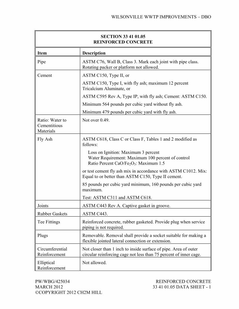
WILSONVILLE WWTP IMPROVEMENTS – DBO
PW/WBG/425034 REINFORCED CONCRETE MARCH 2012 33 41 01.05 DATA SHEET - 1 ©COPYRIGHT 2012 CH2M HILL
SECTION 33 41 01.05 REINFORCED CONCRETE
Item Description
Pipe ASTM C76, Wall B, Class 3. Mark each joint with pipe class. Rotating packer or platform not allowed.
Cement ASTM C150, Type II, or
ASTM C150, Type I, with fly ash; maximum 12 percent Tricalcium Aluminate, or
ASTM C595 Rev A, Type IP, with fly ash; Cement: ASTM C150.
Minimum 564 pounds per cubic yard without fly ash.
Minimum 479 pounds per cubic yard with fly ash.
Ratio: Water to Cementitious Materials
Not over 0.49.
Fly Ash ASTM C618, Class C or Class F, Tables 1 and 2 modified as follows:
Loss on Ignition: Maximum 3 percent Water Requirement: Maximum 100 percent of control Ratio Percent CaO/Fe2O3: Maximum 1.5
or test cement fly ash mix in accordance with ASTM C1012. Mix: Equal to or better than ASTM C150, Type II cement.
85 pounds per cubic yard minimum, 160 pounds per cubic yard maximum.
Test: ASTM C311 and ASTM C618.
Joints ASTM C443 Rev A. Captive gasket in groove.
Rubber Gaskets ASTM C443.
Tee Fittings Reinforced concrete, rubber gasketed. Provide plug when service piping is not required.
Plugs Removable. Removal shall provide a socket suitable for making a flexible jointed lateral connection or extension.
Circumferential Reinforcement
Not closer than 1 inch to inside surface of pipe. Area of outer circular reinforcing cage not less than 75 percent of inner cage.
Elliptical Reinforcement
Not allowed.

WILSONVILLE WWTP IMPROVEMENTS – DBO
REINFORCED CONCRETE PW/WBG/425034 33 41 01.05 DATA SHEET - 2 MARCH 2012 ©COPYRIGHT 2012 CH2M HILL
SECTION 33 41 01.05 REINFORCED CONCRETE
Item Description
Source Quality Control Testing
Load Bearing 0.01-inch Crack, Compressive Strength and Absorption: ASTM C76.
Load Bearing Ultimate: ASTM C76.
Permeability: ASTM C497.
Voids: Longitudinally sawcut one pipe from each 100 lengths of pipe manufactured in half with saw that will not damage the concrete or reinforcing steel. Inspect for voids adjacent to circumferential bars. Voids will be considered continuous if a 1/16-inch diameter pin can be inserted 1/4 inch deep. If voids exist adjacent to more than 10 percent of the circumferential bars, two additional pipes shall be tested. If either of the two pipes fail, the entire 100 lengths will be rejected.
END OF SECTION

WILSONVILLE WWTP IMPROVEMENTS – DBO
PW/WBG/425034 POLYVINYL CHLORIDE (PVC) MARCH 2012 UNDERDRAIN ©COPYRIGHT 2012 CH2M HILL 33 41 01.09 DATA SHEET - 1
SECTION 33 41 01.09 POLYVINYL CHLORIDE (PVC) UNDERDRAIN
Item Description
PVC SDR 26 8-inch diameter Schedule 80 perforated and nonperforated polyvinyl chloride drainage pipe meeting the requirements of Section 33 05 01.09, Polyvinyl Chloride (PVC) Pressure Pipe and Fittings.
Perforated pipe shall provide water inlet of at least 1-1/2 square inch per foot of pipe length. Perforations shall be clean, smooth, and completely free of burrs, frayed edges, or similar defects, and shall not exceed 0.02-inch (0.51-mm) to 0.03-inch (0.76-mm) width or 1-1/2 inches length. Circular perforations will not be acceptable. Perforations shall be minimum of two rows on the bottom side separated by 120 to 145 degrees.
Produce sufficient thread length on coupled joints to ensure full engagement when screwed home in fittings. Make connections with not more than three threads exposed.
Countersink pipe ends, ream and clean chips and burrs after treading.
Use strap wrench for tightening threaded plastic pipe joints. Do not over tighten fittings.
Pipe fittings and connections shall be by the same manufacture as the PVC pipe. Couplings for all pipe, whether perforated or nonperforated, shall be a watertight connection. Fittings and couplings shall not reduce or impair the overall integrity or function of the pipe.
Constructing of Underdrain Pipe
Preparation of Trench: In areas for perforated drain pipe placement, excavation for the drain trench or pipe trench shall be made after embankment has been placed 2 feet above the pipe invert. Excavate the trench as shown on Drawings and as specified.
Removal of Water: At all times, provide and maintain ample means and devices to remove and dispose of water entering the trench during the laying operation to the extent required to properly join the pipe and allow for proper compaction of the backfill in the pipe zone. Do not lay pipe in water.

POLYVINYL CHLORIDE (PVC) PW/WBG/425034 UNDERDRAIN MARCH 2012 33 41 01.09 DATA SHEET - 2 ©COPYRIGHT 2012 CH2M HILL
SECTION 33 41 01.09 POLYVINYL CHLORIDE (PVC) UNDERDRAIN
Item Description
Review of Pipe Prior to Backfilling: All pipe and fittings shall be reviewed by CH2M HILL’s Engineer prior to installation. Any drain pipe or fittings, which are broken, cracked, or otherwise unsuitable, as determined by CH2M HILL, shall be removed and replaced.
Handling of Pipe: Protect pipe from sunlight during storage. The method of laying the drainage pipe shall be such as to prevent damage and excessive stretching of the pipe during laying operations. Stretch in excess of 2 feet per 100 feet of the preinstalled length will not be permitted.
Couplings and Fittings: Couplings shall maintain alignment of the drainage tubing and prevent separation of the joints. Installing couplings, fittings, and jointing shall conform to manufacturer’s instructions. Under no circumstances shall joints be made by any method other than through the use of manufacturer’s standard fittings.
Angle Points in Pipe: Angle points and curved alignment in the drain pipe shall be constructed by deflecting the tubing into a smooth circular arc. The minimum radius bend shall be 18 feet.
Installation of Pipe: The drainage pipe shall be laid to lines and grades as shown on Drawings. Minimum slope shall be 0.5 percent. Lay perforated pipe with the slots down. No portion of the underdrain system shall be placed with adverse slopes. End plugs shall be placed on the upper ends of the perforated drains. Install cleanouts as shown or as directed by CH2M HILL’s Engineer.
Travel Over Drain Pipe: Travel over any portion of the drain pipe will not be permitted until a minimum of 3 feet of cover has been placed over the drainage pipe. Provide additional cover necessary to avoid damage to the drain pipe due to construction equipment loads.
Prior to placing end caps, flush with water, all perforated drain pipes. Flush with sufficient water to remove loose soil or debris that may have entered pipe during construction. Observe discharge of pipe being flushed and continue to flush until discharge water is clean. Inform CH2M HILL’s Engineer a minimum of 24 hours prior to flushing pipes.
END OF SECTION

WILSONVILLE WWTP IMPROVEMENTS – DBO
PW/WBG/425034 FABRICATED SLIDE GATES MARCH 2012 35 20 16.25 - 1 ©COPYRIGHT 2012 CH2M HILL
SECTION 35 20 16.25 FABRICATED SLIDE GATES
PART 1 GENERAL
1.01 RELATED SECTIONS
A. Related sections include the following:
1. Division 1, General Requirements. 2. Section 05 50 00, Metal Fabrications. 3. Section 26 20 00, Low-Voltage AC Induction Motors.
1.02 REFERENCES
A. The following is a list of standards which may be referenced in this Section:
1. American Water Works Association (AWWA): C513, Open-Channel, Fabricated-Metal Slide Gates.
2. American National Standards Institute (ANSI)/American Welding Society (AWS): D1.2/D1.2M, Structural Welding Code – Aluminum.
3. ASTM International (ASTM): a. B26, Standard Specification for Aluminum-Alloy Sand Castings. b. B209, Standard Specification for Aluminum and Aluminum-Alloy
Sheet Plate. c. B221, Standard Specification for Aluminum and Aluminum-Alloy
Extruded Bars, Rods, Wire, Profiles, and Tubes. d. B241, Standard Specification for Aluminum and Aluminum-Alloy
Seamless Pipe and Seamless Extruded Tube. e. B308, Standard Specification for Aluminum-Alloy 6061-T6
Standard Structural Profiles. f. D4020, Standard Specifications for Ultra-High-Molecular-Weight
Polyethylene Molding and Extrusion Materials. 4. National Electrical Manufacturers Association (NEMA): 250,
Enclosures for Electrical Equipment (1,000 Volts Maximum).
1.03 DEFINITIONS
A. Submersible: The ability to exclude water when submerged under a 20-foot head of fresh water for 24 hours and still maintain electrical integrity.
B. Slenderness Ratio: The ratio of the maximum unsupported stem length to the stem cross-section radius of gyration.
WILSONVILLE WWTP IMPROVEMENTS – DBO
FABRICATED SLIDE GATES PW/WBG/425034 35 20 16.25 - 2 MARCH 2012 ©COPYRIGHT 2012 CH2M HILL
C. Self-Contained: The arrangement of gate operator, supported by gate frame, such that operating thrust loads are not applied external to the assembly.
1.04 SUBMITTALS
A. Action Submittals:
1. Shop Drawings: a. Make, model, weight, and horsepower of each equipment
assembly. b. Manufacturer’s catalog information, descriptive literature,
specifications, and identification of materials of construction. c. Detailed structural, mechanical, and electrical drawings showing
the equipment fabrications and interface with other items. Include dimensions, size, and locations of connections to other work, and weights of associated equipment associated therewith.
d. Gate operator and stem calculations for each gate and service condition.
e. Gate opening and closing thrust forces that will be transmitted to the support structure with operator at extreme positions and load.
f. Power and control wiring diagrams, including terminals and numbers.
g. Performance Test Procedures. h. Anchorage and bracing drawings and catalog information, as
required in Section 01 88 15, Anchorage and Bracing, for loads in Section 01 61 00, Common Product Requirements.
B. Informational Submittals:
1. Anchorage and bracing calculations as required in Section 01 88 15, Anchorage and Bracing, for loads in Section 01 61 00, Common Product Requirements.
2. Manufacturer’s Certificate of Compliance, including leakage rate and gate force calculations.
3. Special shipping, storage and protection, and handling instructions. 4. Manufacturer’s written/printed installation instructions. 5. Operation and Maintenance Data: As specified in Section 01 78 23,
Operation, Maintenance, and Asset Data. 6. Manufacturer’s Certificate of Proper Installation in accordance with
Section 01 43 33, Manufacturers’ Field Services. Include leakage test results in accordance with Article Field Quality Control.
7. Service records for maintenance performed during construction, including proof of pickling and passivating any field weld repairs in accordance with ASTM A380.

WILSONVILLE WWTP IMPROVEMENTS – DBO
PW/WBG/425034 FABRICATED SLIDE GATES MARCH 2012 35 20 16.25 - 3 ©COPYRIGHT 2012 CH2M HILL
1.05 SYSTEM DESCRIPTION
A. Coordinate such that electric motor operators are fully assembled and tested, including motor, at the factory.
PART 2 PRODUCTS
2.01 SUPPLEMENTS
A. Refer to the Schedule listed as a Supplement to this Section for additional product information.
2.02 MATERIALS
A. Refer to the Schedule at the end of this Section.
B. Aluminum:
1. Plate and Shapes: ASTM B209, B221, B241, and B308, Alloy 6061-T6.
C. Welds: All welds shall be grinded smooth. After welding, remove contamination in accordance with the requirements of ASTM A380 and ASTM A967. Cleaning shall include removal of all heat tint scale.
2.03 PERFORMANCE REQUIREMENTS
A. Leakage shall not exceed 0.1 gallon per minute per foot of gate periphery for given head conditions.
B. Gates requiring top seals for submerged service shall be manufactured in accordance with AWWA C561. Refer to the Schedule at the end of this Section for top-sealing gates.
2.04 SLIDE GATES
A. Rising stem type, with assembly styles designated as follows:
1. Style A: Upward acting slide gate for wall surface mounting on concrete structures, wall face mounted frame with wall mounted invert.
2. Style B: Upward acting slide gate for wall surface mounting on concrete structures, wall face mounted frame with flush concrete embedded invert.
3. Style C: Upward acting slide gate for in-channel mounting on concrete structures, concrete embedded frame with flush concrete embedded invert.
4. Style D: Downward acting weir gate for wall surface mounting on concrete structures, wall face mounted frame with wall mounted invert.
WILSONVILLE WWTP IMPROVEMENTS – DBO
FABRICATED SLIDE GATES PW/WBG/425034 35 20 16.25 - 4 MARCH 2012 ©COPYRIGHT 2012 CH2M HILL
5. Style E: Downward acting weir gate for in-channel mounting on concrete structures, concrete embedded frame with wall face mounted invert.
B. Guide Frames:
1. Aluminum, 3/8-inch minimum thickness. 2. Vertical Guides: Design for maximum rigidity, and extend in one
continuous piece from the gate invert to form posts for support of gate operators of self-contained gates. When guides extended above the operating floor, they shall be sufficiently strong so that no further reinforcements are required. a. Weight: Not less than 4 pounds per linear foot for aluminum. b. Incorporate a replaceable UHMW polyethylene bearing strip in a
retainer slot on both the upstream and downstream (seating and unseating head) sides of the gate.
3. Frame Invert: For flush bottom gate, furnish a neoprene insert to function as a seating surface for the gate disc. a. Weight: Not less than 2 pounds per linear foot for aluminum.
4. Join vertical guide frames and invert with factory welded corners. 5. Size guided slot to provide a minimum disc engagement of 1 inch on
each side.
C. Disc:
1. Disc Plate (Sliding Member): One single aluminum plate, 3/8-inch minimum thickness. Reinforce as required so that the disc will not deflect more than 1/360 of the gate span, or 1/16 inch, whichever is less, when the upstream liquid depth (seating head) side is as shown on the Schedule and the downstream liquid depth is less than 1/2 inch.
2. Disc Stiffeners: Reinforce gate disc with one-piece aluminum angles or channels welded to the disc plate. Stiffeners shall be 3/8-inch minimum thickness. Bolted reinforcements will not be permitted.
D. Operator Support Yoke:
1. For self-contained gate operators, attached to the vertical extensions of the guide frames.
2. Constructed from at least two aluminum angles, or two other suitable shapes, and bolt in place to provide a rigid assembly.
3. Maximum Deflection: Not to exceed 1/360 of the gate span, or 1/4 inch, whichever is less, under full operator applied loading.
E. Stems:
1. 1-1/2-inch minimum diameter, ASTM A276, Type 316 stainless steel.
WILSONVILLE WWTP IMPROVEMENTS – DBO
PW/WBG/425034 FABRICATED SLIDE GATES MARCH 2012 35 20 16.25 - 5 ©COPYRIGHT 2012 CH2M HILL
2. Threads: Full depth Acme type with RMS surface roughness of 32 microinches or less on the flanks for manually operated gates and 16 microinches or less on the flanks for electrically operated gates. Extend threaded portion of stem 2 inches above operator when gate is in CLOSED position.
3. Ratio of the unsupported stem length to the radius of gyration, both in inches, shall not exceed 200.
4. Stems to withstand in compression, without damage, the thrust equal to at least 2-1/2 times the rated output of the hoisting mechanism, with a 40-pound effort applied to the handwheel or crank.
5. Design electric motor-driven floor stands to withstand at least 1.25 times the output thrust of the motor in the stalled condition.
6. Provide equipment operating stems with UHMW-bushed stem guides, mounted on stainless steel brackets; adjustable in two directions and spaced so that the L/r ratio does not exceed 200.
7. Adjustable stop collar for the CLOSED position. 8. Connect the stems to the disc plate with a yoke, bolted to the stem and
welded to the disc.
F. Stem Covers: Clear or translucent for viewing stem, built of Schedule 80 PVC or Lexan type material that will not crack or discolor or become opaque within 5 years of installation, included with vented pipe stem cover and cap.
G. Manufacturers:
1. Whipps, Inc. 2. Golden Harvest, Inc.
2.05 GATE OPERATORS
A. General:
1. Components: Withstand a minimum of 250 percent of design torque or thrust at extreme operator positions without damage.
2. Mount at walkway level, 36 inches above floor, unless otherwise indicated.
3. Gear train and gate stem sections shall produce a self-locking drive train.
4. Solid Bronze Lift Nuts: Internally threaded with cut or cold-rolled Acme threads corresponding to stem threading.
5. Roller Bearings: a. Located above and below lift nut to support both opening and
closing thrusts. b. Ball-thrust or tapered type. Plastic rings are not acceptable. c. Grease lubrication fittings for bearings.
WILSONVILLE WWTP IMPROVEMENTS – DBO
FABRICATED SLIDE GATES PW/WBG/425034 35 20 16.25 - 6 MARCH 2012 ©COPYRIGHT 2012 CH2M HILL
d. Stainless steel input pinions with needle or ball bearings. e. Mechanical seals at housing penetrations.
6. Lubrication: Furnish rising stem gates with an insert lubricator flange in lift, with grease fitting for greasing stem threads below stem nut.
B. Operator Types:
1. Type 1, Handwheel-Operated Bench Stands: a. Direct drive. b. Handwheel and Baseplate: Cast iron or cast aluminum. c. Manual Effort: Not to exceed 40 pounds.
2. Type 2, Crank-Operated Bench Stands: a. Weatherproof housings, mounted on high-strength cast iron or
cast aluminum base to the top horizontal member of the slide gate frame as described under paragraph Operator Support Yoke.
b. Maximum manual crank effort to operate gate shall not exceed 40 pounds.
c. Crank shall be suitable for portable electric drill operation after removal of handcrank.
3. Type 3, Geared Floor Stands: a. Crank-operated, with weatherproof housings. b. Mount on cast iron or cast aluminum pedestal or base. c. Maximum manual crank effort to operate gate shall not exceed
40 pounds. d. Crank shall be suitable for portable electric drill operation after
removal of handcrank. 4. Type 4, Electric Motor Operators:
a. 28-inch-high cast iron or cast aluminum pedestal or direct yoke-mounted, totally enclosed weatherproof electric drive unit, and a totally enclosed gear box.
b. Gears: Heat treated alloy steel, supported throughout by antifriction ball or roller bearings and grease lubricated.
c. Automatic double-acting geared limit switches and double-acting torque switches. 1) Gear directly to the operating gear train and shall be “in
step” at all times, whether in motor or manual operation. 2) Wire geared limit switches internally to stop the motor at
the fully OPEN and fully CLOSED positions. 3) Wire torque switches internally so that, in the event of a
mechanical overload in either direction, the motor will be stopped.
d. Equip with side mounted handwheel for manual operation. 1) Include an automatic clutch to positively disengage the
handwheel at any time the drive motor control is energized.
WILSONVILLE WWTP IMPROVEMENTS – DBO
PW/WBG/425034 FABRICATED SLIDE GATES MARCH 2012 35 20 16.25 - 7 ©COPYRIGHT 2012 CH2M HILL
2) Design handwheel operator so that failure of the motorized gearing will not prevent hand operation of the gate.
e. Drive Unit: 1) TENV, 480-volt, three-phase electric motor as specified in
Section 26 20 00, Low-Voltage AC Induction Motors, with integral OPEN/STOP/CLOSE weatherproof pushbuttons, reversing controller, 480/120-volt control power transformer, space heaters in the limit switches and in the control compartments, mechanical dial type position indicator, and transparent plastic pipe stem cover and cap.
2) Furnish motor enclosure with drainage and breathing holes. 3) Self-locking, with approximately 12 inches per minute gate
travel speed, and a rated running torque equal to 20 percent of the motor starting torque at a rated running time of 5 minutes, without exceeding the allowable NEMA temperature rise for the insulation class used.
4) Provide integrally mounted, externally operated, pad-lockable power disconnect switch.
f. Operation: Drive the gate to its fully OPEN or CLOSED position when the OPEN or CLOSED pushbutton is depressed momentarily. Motor shall stop in mid-travel when the STOP button is depressed.
g. Control Options: Provide a controller for each motorized gate operator consisting one of the following control options, as noted in the Slide Gate Schedule, with listed Control Features: 1) Control Option 1: Includes Control Feature A only. 2) Control Option 2: Includes Control Features A and B. 3) Control Option 3: Includes Control Features A, B, and D. 4) Control Option 4: Includes Control Features A and C.
h. Control Features: Provide each motorized gate operator with control options consisting of one or more of the following features, as noted in the Slide Gate Schedule:
Control Feature
A:
Local OPEN/STOP/CLOSE pushbutton station; active when the LOCAL/REMOTE selector switch is in LOCAL position.
Control Feature
B:
End position limit switches; OPEN and CLOSED position switches shall be normally open contacts that close at the end position; contacts shall be dry and rated for 5 amps, 120V ac.
WILSONVILLE WWTP IMPROVEMENTS – DBO
FABRICATED SLIDE GATES PW/WBG/425034 35 20 16.25 - 8 MARCH 2012 ©COPYRIGHT 2012 CH2M HILL
Control Feature
C:
LOCAL/REMOTE weatherproof selector switch and provisions for remote positioning operation. Provide auxiliary contact which closes when LOCAL/REMOTE switch is in REMOTE position.
Receive a 4 to 20 mA dc remote command signal to position the gate from 0 to 100% open, when the LOCAL/REMOTE switch is in REMOTE.
Continuous position output; provide transmitter to generate a 4 to 20 mA dc signal to an external loop in direct proportion to gate position (0 to 100% open); the transmitter shall be factory mounted in a NEMA 250, Type 4 enclosure. Transmitter shall be capable of driving an external load impedance of 350 ohms minimum.
Control Feature
D:
LOCAL/REMOTE weatherproof selector switch and provisions for remote OPEN/CLOSE operation; remote commands will be by way of a four-wire circuit; motor operator shall impress the voltage required to read these contacts and shall go to the commanded position when the command contact is closed in the REMOTE mode. Provide auxiliary contact which closes when LOCAL/REMOTE switch is in REMOTE position.
C. Motorized Gate Operator Manufacturers and Products:
1. Rotork; ‘A’ Range. 2. Auma; Model SA.
D. Identification Tagging Requirements:
1. For each gate operator, 1-1/2-inch minimum diameter heavy brass tag, bearing the gate tag number shown in the Schedule.
2. Attach the tags to the operator by soldered split key rings to that ring and tag cannot be removed. Use block type numbers and letters with 1/4-inch minimum high numbers and letters stamped on and filled with black enamel.
2.06 APPURTENANCES
A. Lifting Lugs: Furnish suitably attached for equipment assemblies and components weighing over 100 pounds.
WILSONVILLE WWTP IMPROVEMENTS – DBO
PW/WBG/425034 FABRICATED SLIDE GATES MARCH 2012 35 20 16.25 - 9 ©COPYRIGHT 2012 CH2M HILL
B. Anchor Bolts: Minimum 1/2-inch diameter (unless a larger minimum size is shown on the Drawings) Type 316 stainless steel as listed in the Area Classification Table on the Drawings; number and size as required by equipment manufacturer and by Subcontractor’s anchorage and bracing design per Section 01 88 15, Anchorage and Bracing. Anchor bolts shall be as specified in Section 05 50 00, Metal Fabrications.
PART 3 EXECUTION
3.01 INSTALLATION
A. In accordance with the manufacturer’s written instructions.
B. Field mount operators after installing gates.
C. Anchor Bolts: Accurately place using templates furnished by equipment manufacturer and as specified in Section 05 50 50, Metal Fabrications.
D. Lubricate stems before operating.
3.02 FIELD QUALITY CONTROL
A. Functional Tests: Conduct on each slide gate.
B. Performance Test:
1. Conduct on each slide gate. 2. Perform under actual or approved simulated operating conditions. 3. Test for a continuous 3-hour period without malfunction. 4. Adjust, realign, or modify units and retest if necessary.
3.03 TRAINING
A. After successful completion of required Field Testing, Supplier shall provide field and classroom training to CH2M HILL operations and maintenance staff.
3.04 SUPPLEMENT
A. The supplement listed below, following “End of Section,” is a part of this Specification.
1. Slide Gate Schedule.
END OF SECTION


WILSONVILLE WWTP IMPROVEMENTS - DBO
TAG EQUIPMENT NAME P&ID MATERIAL ASSEMBLY STYLE YOKE TYPE OPERATOR MOUNT TOP SEAL
REQUIREDWALL OPENING WIDTH (INCHES)
WALL OPENING HEIGHT
(INCHES)
GATE HEIGHT (INCHES)
MINIMUM GATE INVERT ELEVATION - BOTTOM OF GATE WHEN LOWERED
(AFF)
WALL OPENING INVERT ELEVATION
(AFF)
MINIMUM WEIR ELEVATION - TOP OF
GATE WHEN LOWERED (AFF)
MAXIMUM WEIR ELEVATION - TOP OF GATE WHEN RAISED
(AFF)
DESIGN OPERATING
HEAD - SEATING (FT)
DESIGN OPERATING HEAD - UNSEATING
(FT)
MANUAL OPERATOR (WHEEL OR
CRANK)
OPERATOR TYPE CONTROL OPTIONS
GTE10_12501 HEADWORKS INFLUENT CHANNEL GATE 1 09-I-0101 ALUMINUM STYLE A SELF CONTAINED YOKE YES 18 18 18 1'-6" 1'-6" - - 5'-0" 0'-9" CRANK TYPE 2 -
GTE10_12502 HEADWORKS INFLUENT CHANNEL GATE 2 09-I-0101 ALUMINUM STYLE A SELF CONTAINED YOKE YES 18 18 18 1'-6" 1'-6" - - 5'-0" 0'-9" CRANK TYPE 2 -
GTE10_12601 SCREEN CHANNEL INFLUENT GATE 1 09-I-0101 ALUMINUM STYLE C SELF CONTAINED YOKE NO 42 92 68 0'-0" 0'-0" - - 3'-0" 3'-0" CRANK TYPE 2 -
GTE10_12602 SCREEN CHANNEL INFLUENT GATE 2 09-I-0101 ALUMINUM STYLE C SELF CONTAINED YOKE NO 42 92 80 0'-0" 0'-0" - - 3'-0" 3'-0" CRANK TYPE 2 -
GTE10_12603 SCREEN CHANNEL INFLUENT GATE 3 09-I-0101 ALUMINUM STYLE C SELF CONTAINED YOKE NO 42 92 80 0'-0" 0'-0" - - 3'-0" 3'-0" CRANK TYPE 2 -
GTE10_12701 SCREEN CHANNEL EFFLUENT GATE 1 09-I-0101 ALUMINUM STYLE C SELF CONTAINED YOKE NO 42 92 68 0'-0" 0'-0" - - 3'-0" 3'-0" CRANK TYPE 2 -
GTE10_12702 SCREEN CHANNEL EFFLUENT GATE 2 09-I-0101 ALUMINUM STYLE C SELF CONTAINED YOKE NO 42 92 80 0'-0" 0'-0" - - 3'-0" 3'-0" CRANK TYPE 2 -
GTE10_12703 SCREEN CHANNEL EFFLUENT GATE 3 09-I-0101 ALUMINUM STYLE C SELF CONTAINED YOKE NO 42 92 80 0'-0" 0'-0" - - 3'-0" 3'-0" CRANK TYPE 2 -
GTE10._32101 GRIT BASIN INFLUENT GATE 1 09-I-0104 ALUMINUM STYLE C SELF CONTAINED YOKE NO 30 92 92 0'-0" 0'-0" - - 3'-0" 3'-0" CRANK TYPE 2 -
GTE10_32102 GRIT BASIN EFFLUENT GATE 2 09-I-0104 ALUMINUM STYLE C SELF CONTAINED YOKE NO 60 80 80 0'-0" 0'-0" - - 3'-0" 3'-0" CRANK TYPE 2 -
GTE10_32103 GRIT BASIN BYPASS GATE 3 09-I-0104 ALUMINUM STYLE A SELF CONTAINED YOKE NO 42 80 80 1'-0" 1'-0" - - 3'-0" 3'-0" CRANK TYPE 2 -
GTE40_21003 AERATION BASIN 3 EFFLUENT WEIR GATE 09-I-0107 ALUMINUM STYLE D SELF CONTAINED YOKE YES 60 72 84 5'-0" 10'-0" 12'-0" 17'-0" 3'-0" 3'-0" WHEEL TYPE 1 -
GTE70_10001 UV CHANNEL 1 INFLUENT GATE 09-I-0118 ALUMINUM STYLE A SELF CONTAINED YOKE YES 24 24 24 1'-0" 1'-0" - - 9'-0" 1'-0" WHEEL TYPE 1 -
GTE70_10002 UV CHANNEL 1 EFFLUENT WEIR GATE 09-I-0118 ALUMINUM STYLE E SELF CONTAINED YOKE NO 48 90 52 ±0'-6" ±4'-8" 4'-10" 8'-11" 2'-0" 2'-0" WHEEL TYPE 4 OPTION 4
GATE STYLES: OPERATOR TYPES:
STYLE A: UPWARD ACTING SLIDE GATE, SURFACE MOUNTED ON CONCRETE STRUCTURES, WALL FACE MOUNTED FRAME, WALL FACE MOUNTED INVERT. (REFER TO STANDARD DETAIL 3520-281) TYPE 1: HAND WHEEL OPERATED BENCH STANDSTYLE B: UPWARD ACTING SLIDE GATE, SURFACE MOUNTED ON CONCRETE STRUCTURES, WALL FACE MOUNTED FRAME, FLUSH CONCRETE EMBEDDED INVERT. (REFER TO STANDARD DETAIL 3520-282) TYPE 2: HAND CRANK OPERATED BENCH STANDSTYLE C: UPWARD ACTING SLIDE GATE, IN-CHANNEL MOUNTED ON CONCRETE STRUCTURE, CONCRETE EMBEDDED FRAME, FLUSH CONCRETE EMBEDDED INVERT. (REFER TO STANDARD DETAIL 3520-283) TYPE 3: GEARED FLOOR STANDSTYLE D: DOWNWARD ACTING WEIR GATE, SURFACE MOUNTED ON CONCRETE STRUCTURES, WALL FACE MOUNTED FRAME, WALL FACE MOUNTED INVERT. (REFER TO STANDARD DETAIL 3520-284) TYPE 4: ELECTRIC MOTOR OPERATOR (INCLUDING HAND WHEEL FOR MANUAL OVERRIDE)STYLE E: DOWNWARD ACTING WEIR GATE, IN-CHANNEL MOUNTED ON CONCRETE STRUCTURES, CONCRETE EMBEDDED FRAME, WALL FACE MOUNTED INVERT. (REFER TO STANDARD DETAIL 3520-285)STYLE F: DOWNWARD ACTING WEIR GATE, IN-CHANNEL MOUNTED ON CONCRETE STRUCTURES, CONCRETE EMBEDDED FRAME, FLUSH CONCRETE EMBEDDED INVERT. (N/A THIS PROJECT) CONTROL OPTIONS (SELECT FROM FEATURES BELOW):
OPTION 1: FEATURE "A" ONLYOPTION 2: FEATURES "A" AND "B"OPTION 3: FEATURES "A", "B", AND "D"OPTION 4: FEATURES "A" AND "C"
CONTROLS FEATURES:A = OPEN-STOP-CLOSE LOCAL CONTROL STATIONB = OPEN-CLOSE WITH 5 AMP, 120 VAC END POSITION LIMIT SWITCHESC = LOCAL-REMOTE SELECTOR SWITCH FOR MODULATING 4 to 20 mAMP LOOP CONTROLD = LOCAL-REMOTE SELECTOR SWITCH FOR REMOTE OPEN-CLOSE OPERATION
WILSONVILLE WWTP IMPROVEMENTS - DBO
SLIDE GATE SCHEDULE
PW/WBG/425034MARCH 2012©COPYRIGHT 2012 CH2M HILL
FABRICATED SLIDE GATES35 20 16.25 SUPPLEMENT - 1


WILSONVILLE WWTP IMPROVEMENTS – DBO
PW/WBG/425034 PIPING SUPPORT SYSTEMS MARCH 2012 40 05 15 - 1 ©COPYRIGHT 2012 CH2M HILL
SECTION 40 05 15 PIPING SUPPORT SYSTEMS
PART 1 GENERAL
1.01 RELATED SECTIONS
A. Related sections include the following:
1. Division 1, General Requirements. 2. Section 05 50 00, Metal Fabrications. 3. Section 09 90 00, Painting and Coating.
1.02 REFERENCES
A. The following is a list of standards which may be referenced in this Section:
1. American Society of Civil Engineers (ASCE): 7, Minimum Design Loads for Buildings and Other Structures.
2. American Society of Mechanical Engineers (ASME): B31.1, Power Piping.
3. ASTM International (ASTM): a. A123/A123M, Standard Specification for Zinc (Hot-Dip
Galvanized) Coatings on Iron and Steel Products. b. A653/A653M, Standard Specification for Steel Sheet, Zinc-
Coated (Galvanized) or Zinc-Iron Alloy-Coated (Galvanealed) by the Hot-Dip Process.
c. E84, Standard Test Method for Surface Burning Characteristics of Building Materials.
4. International Code Council (ICC): a. International Building Code (IBC). b. International Mechanical Code (IMC).
5. Manufacturers’ Standardization Society (MSS): a. SP 58, Pipe Hangers and Supports - Materials, Design and
Manufacture. b. SP 69, Pipe Hangers and Supports - Selection and Application. c. SP 89, Pipe Hangers and Supports - Fabrication and Installation
Practices. d. SP 127, Bracing for piping Systems, Seismic-Wind-Dynamic
Design, Selection and Application.

WILSONVILLE WWTP IMPROVEMENTS – DBO
PIPING SUPPORT SYSTEMS PW/WBG/425034 40 05 15 - 2 MARCH 2012 ©COPYRIGHT 2012 CH2M HILL
1.03 DEFINITIONS
A. Wetted or Submerged: Submerged, less than 1 foot above liquid surface, below top of channel wall, under cover or slab of channel or tank, or in other damp locations.
1.04 SUBMITTALS
A. Action Submittals:
1. Catalog information for manufactured pipe support components and drawings of piping support system, locating each support, sway brace, seismic brace, hanger, guide, component, and anchor for piping 4 inches and larger. Identify support, hanger, restraint, guide, and anchor type by catalog number and Shop Drawing detail number.
2. Revisions to support systems resulting from changes in related piping system layout and its anchorage and bracing or additions of flexible joints.
3. Anchorage and bracing drawings and catalog information, as required by Section 01 88 15, Anchorage and Bracing, for loads in Section 01 61 00, Common Product Requirements.
B. Informational Submittals:
1. Design calculations for pipe support components based on the applied loads including those noted below. Calculations shall include a summary of design criteria used, design of each type of support, and a summary of resulting load reactions on the supporting structure.
2. Anchorage and bracing calculations as required by Section 01 88 15, Anchorage and Bracing, for loads provided in Section 01 61 00, Common Product Requirements.
3. Maintenance information on piping support system.
1.05 QUALIFICATIONS
A. Piping support systems shall be designed, and shop drawings prepared and sealed, by a registered civil or structural engineer currently licensed in the State of Oregon. The Registered Professional Engineer responsible for design of pipe supports shall have at least 5 years of experience in the pipe support design.

WILSONVILLE WWTP IMPROVEMENTS – DBO
PW/WBG/425034 PIPING SUPPORT SYSTEMS MARCH 2012 40 05 15 - 3 ©COPYRIGHT 2012 CH2M HILL
1.06 DESIGN REQUIREMENTS
A. General:
1. Subcontractor shall be responsible for the design, size, and location of piping support systems for all piping not specifically detailed on the Drawings. Piping support systems designed by the Subcontractor shall conform with the Drawings which includes standard design details.
2. All ALP piping and outdoor foul air piping have been designed by CH2M HILL and are detailed in the Drawings.
3. Piping support systems for large diameter piping, typically 18 inches and larger, have been designed by CH2M HILL and are detailed in the Drawings.
4. Supports and locations for other piping are not a complete design and only serve the purpose of illustrating intent. Pipe supports are shown where specific types and locations are required and show minimum supports needed; additional pipe supports may be required.
5. Select sizes and locate piping support systems throughout each facility, whether shown or not. The absence of pipe supports and details on the Drawings shall not relieve the Subcontractor of responsibility for sizing and providing supports throughout plant.
6. Pipe support types shown represent acceptable pipe support configurations, but are not intended to be fully inclusive of the support systems to be employed.
7. Where possible, manufactured support systems shall be employed. 8. In areas where pipe racks are shown for support of large diameter and/or
multiple piping systems, those racks may also be used as part of the support design for smaller piping to be routed through common areas.
9. Where piping connects to equipment it shall be supported by a pipe support or hanger and not by the equipment, unless allowed by the equipment manufacturer.
10. Design for buoyancy loads when piping is in submerged location.
B. Pipe Support System Design Criteria:
1. Meet requirements of MSS SP 58, MSS SP 69, MSS SP 89, and ASME B31.1, or as modified by this Section.
2. Pipe support systems shall be designed for gravity and thrust loads imposed by weight of pipes or internal pressures, including weight of fluid in pipes and insulation.
3. Coordinate design criteria, including design for seismic loads and wind loads as applicable, with Section 01 61 00, Common Product Requirements, and with criteria provided on the General Structural Note Sheets on the Drawings. Design support systems for coordinated loads.

WILSONVILLE WWTP IMPROVEMENTS – DBO
PIPING SUPPORT SYSTEMS PW/WBG/425034 40 05 15 - 4 MARCH 2012 ©COPYRIGHT 2012 CH2M HILL
4. Design anchors, guides, and restraints with consideration for ambient temperature thermal movements and all pressure thrust loads. Design for test pressures as listed in the Piping Schedule on the Drawings.
5. Consider relative deflections of supports and structural framing systems including roof supports and floor supports and their deflections under loads, when selecting pipe support details.
6. Coordinate pipe support locations and configuration with the building structural system and with other building systems.
7. Do not attach pipe supports to ladders, stairs, or railing systems unless specifically shown on the Drawings.
C. Maximum Support Spacing and Minimum Rod Size:
1. Mild Steel or Ductile Iron Piping:
Pipe Size Maximum Spacing of
Supports/Hangers
Minimum Rod Size for Single Rod
Hangers
1-1/4 inches & smaller
6 feet 1/4-inch
1-1/2 to
2-1/2 inches 8 feet 1/4-inch
3 & 4 inches 10 feet 3/8-inch
6 inches 12 feet 3/8-inch
8 inches 12 feet 1/2-inch
10 & 12 inches 14 feet 5/8-inch
14 inches 16 feet 3/4-inch
16 & 18 inches 16 feet 7/8-inch
20 inches 18 feet 1-inch
24 inches 18 feet 1-1/4-inch
30 inches & larger Shown on Drawings Shown on Drawings
Note that this spacing may require the use of higher load pipe clamps and more than a single point concrete anchor point.
WILSONVILLE WWTP IMPROVEMENTS – DBO
PW/WBG/425034 PIPING SUPPORT SYSTEMS MARCH 2012 40 05 15 - 5 ©COPYRIGHT 2012 CH2M HILL
2. Stainless Steel Piping:
Pipe Size Maximum Spacing of
Supports/Hangers
Minimum Rod Size for Single Rod
Hangers
Less than 1-inch 6 feet 1/4-inch
1 to 4 inches 8 feet 1/4-inch
6 inches 8 feet 3/8-inch
8 to 12 inches 10 feet 1/2-inch
14 & 16 inches 12 feet 5/8-inch
18 & 20 inches 14 feet 3/4-inch
24 inches 14 feet 7/8-inch
3. Plastic Piping:
Pipe Size Maximum Spacing of
Supports/Hangers
Minimum Rod Size for Single Rod
Hangers
Less than or equal to 1-1/2 inches
5 feet 1/4-inch
2 & 2-1/2 inches 7 feet 1/4-inch
3 & 4 inches 8 feet 3/8-inch
6 inches 9 feet 3/8-inch
8 inches 10 feet 1/2-inch
4. Copper Piping (where used to match existing piping systems):
Pipe Size Maximum Spacing of
Supports/Hangers
Minimum Rod Size for Single Rod
Hangers 1-1/4 inches &
smaller 5 feet 1/4-inch
1-1/2 to 2-1/2 inches
6 feet 1/4-inch
3 & 4 inches 8 feet 3/8-inch
D. Vertical Sway Bracing: 10-foot maximum centers, as required by submitted calculations, or as indicated on the Drawings.
WILSONVILLE WWTP IMPROVEMENTS – DBO
PIPING SUPPORT SYSTEMS PW/WBG/425034 40 05 15 - 6 MARCH 2012 ©COPYRIGHT 2012 CH2M HILL
E. Anchoring and Bracing Devices: Design, size, and space support anchoring and bracing devices, including anchor bolts, inserts, and other devices used to anchor and brace supports, to withstand shear and pullout loads imposed by all loadings and actual spacing on each particular support.
F. Existing Support Systems: Use existing supports systems to support new piping only if Contractor:
1. Submits design for adequacy of existing support systems to receive modified loads.
2. Submits design for strengthened support systems to receive modified loads.
PART 2 PRODUCTS
2.01 GENERAL
A. When specified items are not available, fabricate pipe supports to general configuration shown in the details or on Drawings.
B. Materials: Refer to the Area Classification Table on the Drawings.
C. Types listed below describe minimum requirements. Types other than shown may be acceptable, providing that calculations and capacity tables satisfy all load requirements, including thrust and lateral loads.
D. Special support and hanger details may be required for cases where standard catalog supports are inapplicable.
2.02 HANGERS
A. Clevis: MSS SP-58 and SP-69, Type 1.
1. Anvil; Figure 260, sizes 1/2-inch through 30 inches. 2. For Insulated Pipe: Anvil; Figure 260 with insulated saddle system
(ISS) sizes 1/2-inch through 16 inches. 3. B-Line; Figure B3100, sizes 1/2-inch through 30 inches.
B. Adjustable Swivel Split-Ring Pipe Clamp: MSS SP 58 and MSS SP 69, Type 6.
1. Anvil; Figure 104, sizes 3/4-inch through 8 inches. 2. B-Line; Figure B3171, sizes 3/4-inch through 6 inches.
WILSONVILLE WWTP IMPROVEMENTS – DBO
PW/WBG/425034 PIPING SUPPORT SYSTEMS MARCH 2012 40 05 15 - 7 ©COPYRIGHT 2012 CH2M HILL
2.03 SADDLE SUPPORTS
A. Pedestal Type: Schedule 40 pipe stanchion, saddle, and anchoring flange.
1. Nonadjustable Saddle: MSS SP 58 and MSS SP 69, Type 37 with U-bolt. a. Anvil; Figure 259, sizes 4 inches through 18 inches with
Figure 63P base. b. B-Line; Figure B3090, sizes 3/4 inches through 18 inches with
B3088 base. 2. Adjustable Saddle: MSS SP 58 and MSS SP 69, Type 38 with clamp.
a. B-Line; Figure B3093, sizes 1-inch through 18 inches with Figure B3088T base.
b. Anvil; Figure 265, sizes 4 inches through 18 inches with Figure 63T base.
B. Elbow and Flange Supports:
1. Elbow with Adjustable Stanchion: a. Sizes 2-1/2 inches through 18 inches.
1) Anvil; Figure 62A or 62B base. 2. Elbow with Nonadjustable Stanchion:
a. Sizes 2-1/2 inches through 42 inches. 1) Anvil; Figure 63A or 63B base.
3. Flange Support with Adjustable Base: a. Sizes 2 inches through 24 inches.
1) B-Line; B3094, with Figure B3088T base.
2.04 WALL BRACKETS AND SUPPORTS
A. Provide calculations or test results that brackets and supports are adequate for specific location and pipe size.
B. Welded Steel Wall Bracket: MSS SP 58 and MSS SP 69, Type 33 (heavy-duty).
1. Anvil; Figure 199, 3,000-pound rating. 2. B-Line; Figure B3067, 3,000-pound rating.
C. Adjustable “J” hanger MSS SP 58 and MSS SP 69, Type 5:
1. Anvil; Figure 67, sizes 1/2-inch through 6 inches. 2. B-Line; Figure B3690, sizes 1/2-inch through 8 inches.

WILSONVILLE WWTP IMPROVEMENTS – DBO
PIPING SUPPORT SYSTEMS PW/WBG/425034 40 05 15 - 8 MARCH 2012 ©COPYRIGHT 2012 CH2M HILL
D. Offset Pipe Clamp:
1. Anvil; Figure 103, sizes 3/4-inch through 8 inches. 2. B-Line; Figure B3148, sizes 1/2-inch through 12 inches.
E. Channel Type:
1. Unistrut. 2. Anvil; Power-Strut. 3. B-Line; Strut System. 4. Aickinstrut (FRP).
2.05 PIPE CLAMPS
A. Riser Clamp: MSS SP 58 and MSS SP 69, Type 8.
1. Anvil; Figure 261, sizes 3/4-inch through 24 inches. 2. B-Line; Figure B3373, sizes 1/2-inch through 30 inches.
2.06 STEEL PIPE SADDLES
A. Provide 120-degree pipe saddle with bolted segmented saddle plates with base plates drilled for anchors bolts; minimum four 7/8-inch holes for 3/4-inch anchor bolts.
1. Sizes 20 inches though 60 inches. 2. Manufacturer: Piping Technology & Products, Inc.; Fig. 2000 as
modified per above.
2.07 CHANNEL TYPE SUPPORT SYSTEMS
A. Members and Connections: Submit final design drawings and calculations unless Contract Documents provide design.
B. Minimum Channel Size:
1. Steel: 12-gauge, 1-5/8-inch wide. 2. FRP: 1-1/2-inch wide.
C. Fasteners:
1. Steel or Stainless Steel: As specified in Section 05 50 00, Metal Fabrications.
2. Vinyl ester fiber, polyurethane base composite nuts and bolts, or encapsulated steel fasteners.

WILSONVILLE WWTP IMPROVEMENTS – DBO
PW/WBG/425034 PIPING SUPPORT SYSTEMS MARCH 2012 40 05 15 - 9 ©COPYRIGHT 2012 CH2M HILL
D. Manufacturers and Products:
1. B-Line; Strut System. 2. Unistrut. 3. Anvil; Power-Strut. 4. Aickinstrut (FRP System). 5. Enduro-Durostrut (FRP Systems).
2.08 LATERAL FORCE RESTRAINTS
A. Anchoring and bracing shall meet requirements of Section 01 88 15, Anchorage and Bracing, for loads in Section 01 61 00, Common Product Requirements.
B. Where other restraints are not provided, provide lateral and longitudinal restraints for seismic, wind, thrust, thermal and other lateral forces.
2.09 ACCESSORIES
A. Insulation Shields:
1. Type: Galvanized steel or stainless steel, MSS SP 58 and MSS SP 69, Type 40.
2. Manufacturers and Products: a. Anvil; Figure 167, sizes 1/2-inch through 24 inches. b. B-Line; Figure B3151, sizes 1/2-inch through 24 inches.
B. Welding Insulation Saddles:
1. Type: MSS SP 58 and MSS SP 69, Type 39. 2. Manufacturers and Products:
a. Anvil; Figure Series 160, sizes 1-inch through 36 inches. b. B-Line; Figure Series B3160, sizes 1/2-inch through 24 inches.
C. Plastic Pipe Support Channel:
1. Type: Continuous support for plastic pipe and to increase support spacing.
2. Manufacturer and Product: B-Line; Figure Series B3106V, sizes 1/2-inch through 6 inches with Figure B3106 Vee bottom hangers.
D. Hanger Rods, Clevises, Nuts, Sockets, and Turnbuckles: In accordance with MSS SP 58.

WILSONVILLE WWTP IMPROVEMENTS – DBO
PIPING SUPPORT SYSTEMS PW/WBG/425034 40 05 15 - 10 MARCH 2012 ©COPYRIGHT 2012 CH2M HILL
E. Attachments:
1. I-Beam Clamp: Concentric loading type, MSS SP 58 and MSS SP 69, Type 21, Type 28, Type 29, or Type 30 which engage both sides of flange.
2. Concrete Insert: MSS SP 58 and MSS SP 69, Type 18, continuous channel insert with load rating not less than that of hanger rod it supports.
3. Welded Beam Attachment: MSS SP 58 and MSS SP 69, Type 22. a. Anvil; Figure 66. b. B-Line; Figure B3083.
4. U-Channel Concrete Inserts: As specified in Section 05 50 50, Metal Fabrications.
5. Concrete Attachment Plates: a. Anvil; Figure 47, Figure 49 or Figure 52. b. B-Line; Figure B3084, Figure B3085 or Figure B3086.
2.10 INTERMEDIATE PIPE GUIDES
A. Type: Hold down pipe guide.
1. Manufacturer and Product: B-Line; Figure B3552, 1-1/2 inches through 30 inches.
B. Type: U-bolts with double nuts to provide nominal 1/8-inch to 1/4-inch clearance around pipe. MSS SP 58 and MSS SP 69, Type 24.
1. Anvil; Figure 137 and Figure 137S. 2. B-Line; Figure B3188 and Figure B3188NS.
2.11 PIPE ALIGNMENT GUIDES
A. Type: Spider.
B. Manufacturers and Products:
1. Anvil; Figure 255, sizes 1/2-inch through 24 inches. 2. B-Line; Figure B3281 through Figure B3287, sizes: 1/2-inch through
24 inches.
2.12 PIPE ANCHORS
A. Type: Anchor chair with U-bolt strap.
B. Manufacturer and Product: B-Line; Figure B3147A or Figure B3147B.
WILSONVILLE WWTP IMPROVEMENTS – DBO
PW/WBG/425034 PIPING SUPPORT SYSTEMS MARCH 2012 40 05 15 - 11 ©COPYRIGHT 2012 CH2M HILL
2.13 ANCHORING SYSTEMS
A. Anchor Bolts: Minimum 1/2-inch diameter (unless a larger minimum size is shown on the Drawings) Type 316 stainless steel as listed in the Area Classification Table on the Drawings; number and size as required by equipment manufacturer and by Subcontractor’s anchorage and bracing design per Section 01 88 15, Anchorage and Bracing. Anchor bolts shall be as specified in Section 05 50 50, Metal Fabrications.
PART 3 EXECUTION
3.01 INSTALLATION
A. General:
1. Install support systems in accordance with MSS SP 69 and MSS SP 89, unless shown otherwise.
2. Install pipe hanger rods plumb, within 4 degrees of vertical during shut down, start up or operations.
3. Support piping connections to equipment by pipe support and not by equipment.
4. Support large or heavy valves, fittings, and appurtenances independently of connected piping.
5. Support no pipe from pipe above it. 6. Support pipe at changes in direction or in elevation, adjacent to flexible
joints and couplings, and where shown. Supports shall account for all loads.
7. Do not install pipe supports and hangers in equipment access areas or bridge crane runs.
8. Brace hanging pipes against horizontal movement by both longitudinal and lateral sway bracing and to reduce movement after startup.
9. Install lateral supports for wind and seismic loads. 10. Install pipe anchors where required to withstand expansion thrust loads
and to direct and control thermal expansion. 11. Repair mounting surfaces to original condition after attachments are
made. 12. Anchor Bolts: Accurately place using templates furnished by equipment
manufacturer and as specified in Section 05 50 00, Metal Fabrications.
B. Standard Pipe Supports:
1. Horizontal Suspended Piping: a. Single Pipes: Adjustable swivel-ring, split-ring, or clevis hangers. b. Grouped Pipes: Trapeze hanger system.

WILSONVILLE WWTP IMPROVEMENTS – DBO
PIPING SUPPORT SYSTEMS PW/WBG/425034 40 05 15 - 12 MARCH 2012 ©COPYRIGHT 2012 CH2M HILL
2. Horizontal Piping Supported from Walls: a. Single Pipes: Wall brackets or wall clips attached to wall with
anchors. Clips attached to wall mounted framing also acceptable. b. Stacked Piping: Wall mounted framing system and clips
acceptable for piping smaller than 3-inch minimal diameter. c. Piping clamps that resist axial movement of pipe through support
are not acceptable. Use cast iron hanging rolls supported from wall bracket.
3. Horizontal Piping Supported from Floors: a. Stanchion Type:
1) Pedestal type; adjustable with stanchion, saddle, and anchoring flange.
2) Use yoked saddles for piping whose centerline elevation is 18 inches or greater above floor and for exterior installations.
3) Provide minimum 1-1/2-inch grout beneath base plate. b. Floor Mounted Channel Supports:
1) Use for piping smaller than 3-inch nominal diameter running along floors and in trenches at piping elevations lower than can be accommodated using pedestal pipe supports.
2) Attach channel framing to floors with base plate on minimum 1-1/2-inch grout and with anchor bolts.
3) Attach pipe to channel with clips or pipe clamps. 4. Insulated Pipe:
a. Pipe hanger and support shall be on outside of insulation and shall not be enclosed within insulation.
b. Provide precut 120-degree sections of rigid insulation (minimum length same as the shield), galvanized steel shields and oversized hangers or insulated saddle system. Anvil; Figure 260 (ISS).
c. Wall mounted piping clips not acceptable for insulated piping. 5. Vertical Pipe: Support with wall brackets and base elbow or riser
clamps on floor penetrations. 6. Standard Attachments:
a. To Underside of Concrete Slabs: U-Channel Concrete Inserts, U-Channel to Concrete Embed Plates, overhead anchors as specified in Section 05 50 00, Metal Fabrications.
b. To Steel Beams: I-beam clamp or welded attachments. c. To Concrete Walls: Concrete anchors, inserts, brackets or
connections using anchor bolts or concrete anchors. d. To Concrete Beams: U-Channel Concrete Inserts, or if inserts are
not used attach to vertical surface similar to Concrete Wall. Do not drill into beam bottom or lower third of beam.

WILSONVILLE WWTP IMPROVEMENTS – DBO
PW/WBG/425034 PIPING SUPPORT SYSTEMS MARCH 2012 40 05 15 - 13 ©COPYRIGHT 2012 CH2M HILL
e. Existing Walls and Ceilings: Install as specified for new construction, unless shown otherwise.
C. Intermediate and Pipe Alignment Guides:
1. Provide pipe alignment guides (or pipe supports that provide same function) at expansion joints and loops.
2. Guide piping on each side of expansion joint or loop at four pipe and 14-pipe diameters from each joint or loop.
3. Install intermediate guides on metal framing support systems not carrying pipe anchor or alignment guide.
D. Accessories:
1. Insulation Shield: Install on insulated piping. Oversize rollers and supports.
2. Welding Insulation Saddle: Install on insulated steel pipe. Oversize rollers and supports.
3. Dielectric Barrier: a. Provide plastic coated hangers, or isolation tape such as B-Line
Iso Pipe, B-Line B1999 Vibra Cushion, or B-Line B3195 Felt Isolators between painted or galvanized carbon steel members and copper or stainless steel pipe or between stainless steel supports and nonstainless steel ferrous metal piping.
b. Install 1/4-inch by 3-inch neoprene rubber wrap between submerged metal pipe and oversized clamps.
3.02 MATERIALS
A. Refer to the Area Classification Table on the Drawings for types of materials designated to different hazardous locations and environmental conditions.
3.03 FIELD FINISHING
A. As specified in Section 09 90 00, Painting and Coating.
END OF SECTION

WILSONVILLE WWTP IMPROVEMENTS – DBO
PW/WBG/425034 PIPE HEAT TRACING MARCH 2012 40 05 33 - 1 ©COPYRIGHT 2012 CH2M HILL
SECTION 40 05 33 PIPE HEAT TRACING
PART 1 GENERAL
1.01 RELATED SECTIONS
A. Related sections include the following:
1. Division 1, General Requirements. 2. Section 40 27 00, Process Piping—General. 3. Section 40 42 13, Mechanical Insulation.
1.02 REFERENCES
A. The following is a list of standards which may be referenced in this Section:
1. Factory Mutual. 2. Institute of Electrical and Electronics engineers, Inc (IEEE): 515,
Testing, Design, Installation and Maintenance of Electrical Resistance Heat Tracing for Industrial Applications.
3. National Electrical Manufacturers’ Association (NEMA): 250, Enclosures for Electrical Equipment (1000 Volts Maximum).
4. Underwriters Laboratories, Inc. (UL).
1.03 SUBMITTALS
A. Action Submittals:
1. Manufacturer’s descriptive product literature. 2. Pipe heat loss calculations for each pipe size to be heat traced.
PART 2 PRODUCTS
2.01 SYSTEM DESIGN REQUIREMENTS
A. Design Heating Load:
1. Heating load to be calculated based upon a 50 degree F delta, 20 mph wind if pipes are located outdoors, insulation as specified in Section 40 42 13, Mechanical Insulation, pipe as specified in Section 40 27 00, Process Piping—General, and shall include a 10 percent safety factor.
2. Heat loss calculations shall be based on IEEE 515, Equation 1, or most recent revision.

WILSONVILLE WWTP IMPROVEMENTS – DBO
PIPE HEAT TRACING PW/WBG/425034 40 05 33 - 2 MARCH 2012 ©COPYRIGHT 2012 CH2M HILL
B. Refer to the Heat Trace Schedule, P&IDs, Electrical Process Plans and Mechanical Plans and Sections in the Drawings for quantity and extent of pipes to be heat traced. Coordinate final requirements with CH2M HILL field staff before procurement and installation of any heat trace equipment.
2.02 ELECTRICAL HEATING TAPE
A. Cable: Self-limiting, parallel circuit construction consisting of continuous inner core of variable resistance conductive heating material between two parallel copper bus wires. Provide tinned copper braid for PVC, FRP, and stainless steel pipe applications.
B. UL Listing: Listed as self-limiting pipe tracing material for pipe freeze protection application in ordinary conditions.
C. Where installed in Hazardous Classified Areas as identified in the Contract Documents, provide equipment rated for such environments.
D. Maximum Maintenance Temperature: 150 degrees F (65 degrees C).
E. Maximum Intermittent Temperature: 185 degrees F (85 degrees C).
F. Service Voltage: 120V unless otherwise noted.
G. Manufacturers and Products:
1. Raychem. 2. Thermon. 3. Nelson.
2.03 CONNECTION SYSTEM
A. Rating: NEMA 250, Type 4 and Factory Mutual approved.
1. Where installed in Hazardous Classified Areas as identified in the Contract Documents, provide equipment rated for such environments.
B. Operating Monitor Light: Furnish with each circuit power connection kit to indicate when heat tracing is energized.
C. Manufacturers and Products:
1. Power Connection Kit: a. Raychem; JBS-100. b. Thermon; PCA-1-SR or DP-L. c. Nelson; PLT-BC.

WILSONVILLE WWTP IMPROVEMENTS – DBO
PW/WBG/425034 PIPE HEAT TRACING MARCH 2012 40 05 33 - 3 ©COPYRIGHT 2012 CH2M HILL
2. Splice Kit: a. Raychem; S-150. b. Thermon; PCS-1-SR. c. Nelson; PLT-BS.
3. Tee Kit: a. Raychem; T-100. b. Thermon; DS-S. c. Nelson; PLT-BY.
4. End Seal Kit: a. Raychem; E-150. b. Thermon; DE-S. c. Nelson; LT-ME.
5. Lighted End Seal Kit: a. Raychem; E-100-L. b. Thermon; DLS. c. Nelson; LT-L.
2.04 SECURING TAPE
A. Metallic Piping Systems:
1. Type: Glass or polyester cloth pressure sensitive tape. 2. Manufacturers and Products:
a. Raychem; GS54 or GT66. b. Thermon; PF-1. c. Nelson; GT-6 or GT-60.
2.05 PIPE MOUNTED THERMOSTAT
A. Type: Fixed, nonadjustable, set at 40 degrees F.
B. Sensor: Fluid-filled with 3-foot capillary.
C. Enclosure: Glass-filled nylon, NEMA 250, Type 4X weatherproof with gasketed lid.
D. Switch: SP-ST, UL listed, rated 22 amps, 120 to 240V ac.
E. Where installed in Hazardous Classified Areas as identified in the Contract Documents, provide equipment rated for such environments.
F. Manufacturers:
1. Raychem. 2. Thermon. 3. Nelson.

WILSONVILLE WWTP IMPROVEMENTS – DBO
PIPE HEAT TRACING PW/WBG/425034 40 05 33 - 4 MARCH 2012 ©COPYRIGHT 2012 CH2M HILL
2.06 AMBIENT THERMOSTAT
A. Type: Adjustable setting (15 to 140 degrees F).
B. Sensor: Fluid-filled probe.
C. Enclosure: Epoxy-coated NEMA 250, Type 4X aluminum enclosure with exposed hardware of stainless steel.
D. Switch: SP-DT, UL or FM listed, rated 22 amps, 125 to 250V ac.
E. Manufacturers:
1. Raychem. 2. Thermon. 3. Nelson.
PART 3 EXECUTION
3.01 INSTALLATION
A. General:
1. Install in accordance with the manufacturer’s instructions and recommended practices.
2. Provide insulation as specified in Section 40 42 13, Mechanical Insulation, over all pipe heat tracing.
3. Ground metallic structures or materials used for support of heating cable or on which it is installed in accordance with applicable codes.
4. Wiring between power connection points of heat tracing cable branch lines shall be provided by heat tracing system supplier.
5. Provide end of circuit pilot lights on heat tracing circuits for buried piping.
B. Electrical Heating Tape:
1. Determine required length of electrical heating tape by considering length of circuit, pipe size, number and type of fittings and fixtures, design heating load, and heating tape output.
2. Where design heating load exceeds heating tape capacity, install by spiraling.
3. Derate heating tape capacity when installed on plastic piping. 4. Install on services where shown on Drawings.

WILSONVILLE WWTP IMPROVEMENTS – DBO
PW/WBG/425034 PIPE HEAT TRACING MARCH 2012 40 05 33 - 5 ©COPYRIGHT 2012 CH2M HILL
5. Install additional heating tape at bolted flanges, valves, pipe supports, and other fittings and fixtures as recommended by supplier, but not less than the following:
Item Heating Tape Length
(min. feet)
Bolted flanges (per pair) Two times pipe diameter
Valves Four times valve length
Pipe hanger or support penetrating insulation
Three times pipe diameter
C. Heat Tracing Circuits: Limit individual lengths of heat tracing circuits such that maximum single circuit capacity is 20 amps when starting the circuit at 40 degrees F. Provide multiple 20-amp circuits as required at individual heat tracing locations.
D. Thermostats:
1. Install in accordance with manufacturer’s instructions and as approved by Engineer.
2. For each group of heat traced circuit, install one ambient thermostat.
3.02 FIELD QUALITY CONTROL
A. Test each circuit with 500-volt insulation tester between circuit and ground with neutrals isolated from ground.
1. Insulation Resistance: Minimum 1,000 megohms per 1,000 feet.
END OF SECTION

WILSONVILLE WWTP IMPROVEMENTS – DBO
PW/WBG/425034 PROCESS PIPING—GENERAL MARCH 2012 40 27 00 - 1 ©COPYRIGHT 2012 CH2M HILL
SECTION 40 27 00 PROCESS PIPING—GENERAL
PART 1 GENERAL
1.01 RELATED SECTIONS
A. Related sections include the following:
1. Division 1, General Requirements. 2. Section 09 90 00, Painting and Coating. 3. Section 31 23 23.15, Trench Backfill. 4. Section 40 27 01, Process Piping Specialties. 5. Section 40 80 01, Process Piping Leakage Testing.
1.02 REFERENCES
A. The following is a list of standards which may be referenced in this Section and any supplemental Data Sheets:
1. American Society of Mechanical Engineers (ASME): a. Boiler and Pressure Vessel Code, Section IX, Qualification
Standard for Welding and Brazing Procedures, Welders, Brazers, and Welding and Brazing Operators.
b. B16.25, Butt Welding Ends. 2. American Water Works Association (AWWA):
a. C104/A21.4, Cement-Mortar Lining for Ductile-Iron Pipe and Fittings for Water.
b. C105/A21.5, Polyethylene Encasement for Ductile-Iron Pipe Systems.
c. C110/A21.10, Ductile-Iron and Gray-Iron Fittings for Water. d. C111/A21.11, Rubber-Gasket Joints for Ductile-Iron Pressure
Pipe and Fittings. e. C115/A21.15, Flanged Ductile-Iron Pipe with Ductile-Iron or
Gray-Iron Threaded Flanges. f. C116/A21.16, Protective Fusion-Bonded Epoxy Coatings for the
Interior and Exterior Surfaces of Ductile-Iron and Gray-Iron Fittings for Water Supply Service.
g. C151/A21.51, Ductile-Iron Pipe, Centrifugally Cast, for Water. h. C153/A21.53, Ductile-Iron Compact Fittings for Water Service. i. C207, Steel Pipe Flanges for Waterworks Service, Sizes 4 In.
Through 144 In. (100 mm Through 3,600 mm). j. C606, Grooved and Shouldered Joints.
WILSONVILLE WWTP IMPROVEMENTS – DBO
PROCESS PIPING—GENERAL PW/WBG/425034 40 27 00 - 2 MARCH 2012 ©COPYRIGHT 2012 CH2M HILL
3. ASTM International (ASTM): a. A47/A47M, Standard Specification for Ferritic Malleable Iron
Castings. b. A307, Standard Specification for Carbon Steel Bolts and Studs,
60,000 psi Tensile Strength. c. A563, Standard Specification for Carbon and Alloy Steel Nuts.
1.03 SUBMITTALS
A. Action Submittals:
1. Pipe Corrosion Protection: Product data. 2. Pipe and fitting material data including flange rating, wall thickness,
gasket material, and bolt material.
B. Informational Submittals:
1. Manufacturer’s Certification of Compliance: a. Pipe and fittings. b. Welding electrodes and filler materials. c. Factory applied resins and coatings.
2. Qualifications: a. Weld Inspection and Testing Agency: Certification and
qualifications. b. Welding Inspector: Certification and qualifications. c. Welders:
1) List of qualified welders and welding operators. 2) Current test records for qualified welder(s) and weld type(s)
for factory and field welding. 3. Weld Procedures: Records in accordance with ASME Boiler and
Pressure Vessel Code, Section IX for weld type(s) and base metal(s). 4. Nondestructive inspection and testing procedures.
1.04 QUALITY ASSURANCE
A. Qualifications:
1. Independent Inspection and Testing Agency: a. Ten years’ experience in field of welding and welded pipe and
fittings’ testing required for this Project. b. Calibrated instruments and equipment, and documented standard
procedures for performing specified testing. c. Certified in accordance with ASNT SNT-TC-1A for testing
procedures required for this Project.

WILSONVILLE WWTP IMPROVEMENTS – DBO
PW/WBG/425034 PROCESS PIPING—GENERAL MARCH 2012 40 27 00 - 3 ©COPYRIGHT 2012 CH2M HILL
d. Testing Personnel: Qualified for nondestructive test methods to be performed.
e. Inspection Services: Qualified welding inspector. 2. Welding Inspector: AWS certified, AWS QC1 qualified, with prior
inspection experience of welds specified. 3. Welder and Welding Operator Qualifications:
a. Qualified by accepted inspection and testing agency before starting Work in accordance with Section IX, Article III of the ASME Boiler and Pressure Vessel Code.
b. Qualified to perform groove welds in Positions 2G and 5G for each welding process and pipe material specified.
c. Qualification tests may be waived by CH2M HILL based on evidence of prior qualification.
4. Retesting: Upon Engineer’s written request, retest qualified welder(s).
B. Quality Control: Provide services of independent inspection and testing agency for welding operations.
1.05 DELIVERY, STORAGE, AND HANDLING
A. In accordance with Section 01 61 00, Common Product Requirements, and:
1. Flanges: Securely attach metal, hardboard, or wood protectors over entire gasket surface.
2. Threaded or Socket Welding Ends: Fit with metal, wood, or plastic plugs or caps.
3. Linings and Coatings: Prevent excessive drying. 4. Cold Weather Storage: Locate products to prevent coating from freezing
to ground. 5. Handling: Use heavy canvas or nylon slings to lift pipe and fittings.
PART 2 PRODUCTS
2.01 PIPING
A. As specified on Piping Data Sheet(s) located at the end of this Section as Supplements, and Piping Schedule located on the Drawings.
B. Diameters Shown:
1. Standardized Products: Nominal size.
2.02 JOINTS
A. As specified on Piping Data Sheet(s) located at the end of this Section as Supplements, and Piping Schedule located on the Drawings.
WILSONVILLE WWTP IMPROVEMENTS – DBO
PROCESS PIPING—GENERAL PW/WBG/425034 40 27 00 - 4 MARCH 2012 ©COPYRIGHT 2012 CH2M HILL
2.03 GASKET LUBRICANT
A. Lubricant shall be supplied by pipe supplier and no substitute or “or-equal” will be allowed.
2.04 PIPE CORROSION PROTECTION
A. Coatings: Refer to Section 09 90 00, Painting and Coating, for details of coating requirements.
B. Polyethylene Encasement (Bagging):
1. Encasement Tube: Black polyethylene encasement tube, 8 mils minimum thickness, conforming to AWWA C105/A21.5, Class C, free of gels, streaks, pinholes, foreign matter, undispersed raw materials, and visible defects such as tears, blisters, and thinning at folds.
2. Securing Tape: Thermoplastic tape, 8 mils minimum thickness, 1-inch wide, pressure sensitive adhesive face capable of bonding to metal, bituminous coating, and polyethylene encasement tube.
C. Insulating Flanges and Unions:
1. Install insulated flange or dielectric union between all dissimilar pipe material connections and all metallic pipe that transitions from buried to above grade. Locate insulating flange at the first abovegrade flange unless otherwise shown on Drawings.
2. Materials: a. In accordance with applicable piping material specified in Pipe
Data Sheets. Complete assembly shall have ASME B31.9 or B31.3 (depending on service) working pressure rating equal to or higher than that of joint and pipeline.
b. Galvanically compatible with piping. c. Resistant to exposure, operating temperatures, and products
contained in pipeline for intended service. d. Insulating kits shall be NEMA G-10, including but not limited to
gaskets, sleeves, and washers.
PART 3 EXECUTION
3.01 EXAMINATION
A. Verify size, material, joint types, elevation, horizontal location, and pipe service of existing pipelines to be connected to new pipelines or new equipment.

WILSONVILLE WWTP IMPROVEMENTS – DBO
PW/WBG/425034 PROCESS PIPING—GENERAL MARCH 2012 40 27 00 - 5 ©COPYRIGHT 2012 CH2M HILL
B. Inspect size and location of structure penetrations to verify adequacy of wall pipes, sleeves, and other openings.
C. Welding Electrodes: Verify proper grade and type, free of moisture and dampness, and coating is undamaged.
3.02 PREPARATION
A. Notify CH2M HILL’s Engineer at least 2 weeks prior to field fabrication of pipe or fittings.
B. Inspect pipe and fittings before installation, clean ends thoroughly, and remove foreign matter and dirt from inside.
C. Damaged Coatings and Linings: Repair using original coating and lining materials in accordance with supplier’s instructions, except for damaged glass-lined pipe that is to be promptly removed from the Site.
3.03 WELDING
A. Perform in accordance with Section IX, ASME Boiler and Pressure Vessel Code and ASME B31.3 for Pressure Piping, as may be specified on Piping Data Sheets, and if recommended by piping or fitting manufacturer.
B. Weld Identification: Mark each weld with symbol identifying welder.
C. Pipe End Preparation:
1. Machine Shaping: Preferred. 2. Oxygen or Arc Cutting: Smooth to touch, true, and slag removal by
chipping or grinding. 3. Beveled Ends for Butt Welding: ASME B16.25.
D. Surfaces:
1. Clean and free of paint, oil, rust, scale, slag, or other material detrimental to welding.
2. Clean stainless steel joints with stainless steel wire brushes or stainless steel wool prior to welding.
3. Thoroughly clean each layer of deposited weld metal, including final pass, prior to deposition of each additional layer of weld metal with a power-driven wire brush.

WILSONVILLE WWTP IMPROVEMENTS – DBO
PROCESS PIPING—GENERAL PW/WBG/425034 40 27 00 - 6 MARCH 2012 ©COPYRIGHT 2012 CH2M HILL
E. Alignment and Spacing:
1. Align ends to be joined within existing commercial tolerances on diameters, wall thicknesses, and out-of-roundness.
2. Root Opening of Joint: As stated in qualified welding procedure. 3. Minimum Spacing of Circumferential Butt Welds: Minimum four times
pipe wall thickness or 1 inch, whichever is greater.
F. Climatic Conditions:
1. Do not perform welding if there is impingement of any rain, snow, sleet, or high wind on the weld area, or if the ambient temperature is below 32 degrees F.
2. Stainless Steel and Alloy Piping: If the ambient is less than 32 degrees F, local preheating to a temperature warm to the hand is required.
G. Tack Welds: Performed by qualified welder using same procedure as for completed weld, made with electrode similar or equivalent to electrode to be used for first weld pass, and not defective. Remove those not meeting requirements prior to commencing welding procedures.
H. Surface Defects: Chip or grind out those affecting soundness of weld.
I. Weld Passes: As required in welding procedure.
J. Weld Quality: Free of cracks, incomplete penetration, weld undercutting, excessive weld reinforcement, porosity slag inclusions, and other defects in excess of limits shown in applicable piping code.
3.04 INSTALLATION—GENERAL
A. Join pipe and fittings in accordance with supplier’s instructions, unless otherwise shown or specified.
B. Remove foreign objects prior to assembly and installation.
C. Ductile Iron Piping:
1. Cutting Pipe: Cut pipe with milling type cutter, rolling pipe cutter, or abrasive blade cutter. Do not flame cut.
2. Dressing Cut Ends: a. General: As required for the type of joint to be made. b. Rubber Gasketed Joints: Remove sharp edges or projections. c. Push-On Joints: Bevel, as recommended by pipe supplier.

WILSONVILLE WWTP IMPROVEMENTS – DBO
PW/WBG/425034 PROCESS PIPING—GENERAL MARCH 2012 40 27 00 - 7 ©COPYRIGHT 2012 CH2M HILL
d. Flexible Couplings, Flanged Coupling Adapters, and Grooved End Pipe Couplings: As recommended by the coupling or adapter supplier.
3.05 INSTALLATION—BURIED PIPE
A. Placement:
1. Keep trench dry until pipe laying and joining are completed. 2. Pipe Base and Pipe Zone: As specified in Section 31 23 23.15, Trench
Backfill. 3. Exercise care when lowering pipe into trench to prevent twisting or
damage to pipe. 4. Measure for grade at pipe invert, not at top of pipe. 5. Excavate trench bottom and sides of ample dimensions to permit visual
inspection and testing of entire flange, valve, or connection. 6. Prevent foreign material from entering pipe during placement. 7. Close and block open end of last laid pipe section when placement
operations are not in progress and at close of day’s work. 8. Lay pipe upgrade with bell ends pointing in direction of laying. 9. Deflect pipe at joints for pipelines laid on a curve using unsymmetrical
closure of spigot into bell. If joint deflection of standard pipe lengths will not accommodate horizontal or vertical curves in alignment, provide: a. Shorter pipe lengths. b. Special mitered joints. c. Standard or special fabricated bends.
10. After joint has been made, check pipe alignment and grade. 11. Place sufficient pipe zone material to secure pipe from movement
before next joint is installed. 12. Prevent uplift and floating of pipe prior to backfilling.
B. Tolerances:
1. Deflection From Horizontal Line, Except PVC, CPVC, or HDPE: Maximum 2 inches.
2. Deflection From Vertical Grade: Maximum 1/4 inch. 3. Joint Deflection: Maximum of 75 percent of supplier’s
recommendation. 4. Horizontal position of pipe centerline on alignment around curves
maximum variation of 1.75 feet from position shown. 5. Pipe Cover: Minimum 3 feet, unless otherwise shown.

WILSONVILLE WWTP IMPROVEMENTS – DBO
PROCESS PIPING—GENERAL PW/WBG/425034 40 27 00 - 8 MARCH 2012 ©COPYRIGHT 2012 CH2M HILL
3.06 PIPE CORROSION PROTECTION
A. Ductile Iron Pipe:
1. Buried: Wrap with polyethylene bagging.
B. Piping Accessories:
1. Insulating Flanges or Dielectric Unions: Install on all dissimilar pipe material connections and all metallic pipe that transitions from buried to above grade. Locate insulating flanges at the first above grade flange unless otherwise shown on Drawings.
2. Buried: a. Ferrous Metal and Stainless Steel Components: Coat with coal-tar
epoxy. b. Bolts, Nuts, and Similar Items: Coat with bituminous paint. c. Flexible Couplings, Grooved Couplings, and Similar Items:
Fusion bonded epoxy coating, with Type 316 stainless steel bolts, in accordance with System No. 29, as specified in Section 09 90 00, Painting and Coating.
d. Buried Valves and Similar Elements on Wrapped Pipelines: Coat with bituminous paint and wrap entire valve in polyethylene encasement.
e. Cement-Coated Pipelines: Cement coat appurtenances same as pipe.
C. Polyethylene Encasement: Install in accordance with AWWA C105/A21.5 and manufacturer’s instructions.
D. Verify all pipe is electrically isolated from reinforcing steel prior to backfill or concrete encasement.
3.07 THRUST RESTRAINT
A. Location:
1. Buried Piping: Where shown and where required to restrain force developed at pipeline tees, plugs, caps, bends, and other locations where unbalanced forces exist because of hydrostatic testing and normal operating pressure.
3.08 PIPE IDENTIFICATION
A. As specified in Section 31 23 23.15, Trench Backfill.
WILSONVILLE WWTP IMPROVEMENTS – DBO
PW/WBG/425034 PROCESS PIPING—GENERAL MARCH 2012 40 27 00 - 9 ©COPYRIGHT 2012 CH2M HILL
3.09 FIELD QUALITY CONTROL
A. Pressure Leakage Testing: As specified in Section 40 80 01, Process Piping Leakage Testing, unless otherwise indicated on the Piping Schedule.
B. Minimum Duties of Welding Inspector:
1. Job material verification and storage. 2. Qualification of welders. 3. Certify conformance with approved welding procedures. 4. Maintenance of records and preparation of reports in a timely manner. 5. Notification to CH2M HILL of unsatisfactory weld performance within
24 hours of weld test failure.
C. Required Weld Examinations:
1. Perform examinations in accordance with Piping Code, ASME B31.3. 2. Perform examinations for every pipe thickness and for each welding
procedure, progressively, for all piping covered by this Section. 3. Examine at least one of each type and position of weld made by each
welder or welding operator. 4. For each weld found to be defective under the acceptance standards or
limitations on imperfections contained in the applicable Piping Code, examine two additional welds made by the same welder that produced the defective weld. Such additional examinations are in addition to the minimum required above. Examine, progressively, two additional welds for each tracer examination found to be unsatisfactory.
3.10 SUPPLEMENTS
A. The supplements listed below, following “End of Section,” are a part of this Specification:
1. Data Sheets.
Number Title
40 27 00.01 Cement-Mortar or Glass-Lined Ductile Iron Pipe and Fittings
40 27 00.03 Carbon Steel Pipe and Fittings
40 27 00.07 Galvanized Steel Pipe and Malleable Iron Fittings
40 27 00.08 Stainless Steel Pipe and Fittings
40 27 00.10 Polyvinyl Chloride (PVC) Pipe and Fittings

WILSONVILLE WWTP IMPROVEMENTS – DBO
PROCESS PIPING—GENERAL PW/WBG/425034 40 27 00 - 10 MARCH 2012 ©COPYRIGHT 2012 CH2M HILL
Number Title
40 27 00.13 Copper and Copper Alloy Pipe, Tubing, and Fittings
40 27 00.19 High-Density Polyethylene (HDPE) Pipe and Fittings
40 27 00.21 Profile Wall Polyethylene (PWPE)
END OF SECTION
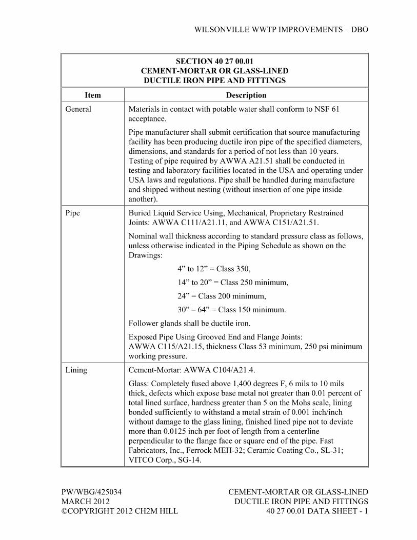
WILSONVILLE WWTP IMPROVEMENTS – DBO
PW/WBG/425034 CEMENT-MORTAR OR GLASS-LINED MARCH 2012 DUCTILE IRON PIPE AND FITTINGS ©COPYRIGHT 2012 CH2M HILL 40 27 00.01 DATA SHEET - 1
SECTION 40 27 00.01 CEMENT-MORTAR OR GLASS-LINED DUCTILE IRON PIPE AND FITTINGS
Item Description
General Materials in contact with potable water shall conform to NSF 61 acceptance.
Pipe manufacturer shall submit certification that source manufacturing facility has been producing ductile iron pipe of the specified diameters, dimensions, and standards for a period of not less than 10 years. Testing of pipe required by AWWA A21.51 shall be conducted in testing and laboratory facilities located in the USA and operating under USA laws and regulations. Pipe shall be handled during manufacture and shipped without nesting (without insertion of one pipe inside another).
Pipe Buried Liquid Service Using, Mechanical, Proprietary Restrained Joints: AWWA C111/A21.11, and AWWA C151/A21.51.
Nominal wall thickness according to standard pressure class as follows, unless otherwise indicated in the Piping Schedule as shown on the Drawings:
4” to 12” = Class 350,
14” to 20” = Class 250 minimum,
24” = Class 200 minimum,
30” – 64” = Class 150 minimum.
Follower glands shall be ductile iron.
Exposed Pipe Using Grooved End and Flange Joints: AWWA C115/A21.15, thickness Class 53 minimum, 250 psi minimum working pressure.
Lining Cement-Mortar: AWWA C104/A21.4.
Glass: Completely fused above 1,400 degrees F, 6 mils to 10 mils thick, defects which expose base metal not greater than 0.01 percent of total lined surface, hardness greater than 5 on the Mohs scale, lining bonded sufficiently to withstand a metal strain of 0.001 inch/inch without damage to the glass lining, finished lined pipe not to deviate more than 0.0125 inch per foot of length from a centerline perpendicular to the flange face or square end of the pipe. Fast Fabricators, Inc., Ferrock MEH-32; Ceramic Coating Co., SL-31; VITCO Corp., SG-14.

WILSONVILLE WWTP IMPROVEMENTS – DBO
CEMENT-MORTAR OR GLASS-LINED PW/WBG/425034 DUCTILE IRON PIPE AND FITTINGS MARCH 2012 40 27 00.01 DATA SHEET - 2 ©COPYRIGHT 2012 CH2M HILL
SECTION 40 27 00.01 CEMENT-MORTAR OR GLASS-LINED DUCTILE IRON PIPE AND FITTINGS
Item Description
Fittings Lined and coated same as pipe.
Mechanical: AWWA C110/A21.10, AWWA C111/A21.11, and AWWA C153/A21.53 ductile iron, 250 psi minimum working pressure. Follower glands shall be ductile iron. Provide with mechanical joint anchor gland followers for restrained joint systems.
Grooved End: AWWA C606 and AWWA C110/A21.10, ductile iron, 250 psi minimum working pressure; Victaulic.
Flange: AWWA C110/A21.10 ductile iron, faced and drilled, Class 125 flat face. Gray cast iron will not be allowed.
Joints Mechanical: 250 psi minimum working pressure. Provide with mechanical joint anchor gland follower for restrained joint systems.
Grooved End: Rigid type radius cut conforming to AWWA C606, 250 psi minimum working pressure; Victaulic.
Flange: Class 125 flat face, ductile iron, threaded conforming to AWWA C115/A21.15. Gray cast iron will not be allowed.
Branch connections 3 inches and smaller, except from glass-lined pipe, shall be made with service saddles as specified in Section 40 27 01, Process Piping Specialties. Branch connections, 3 inches and smaller from glass-lined pipe shall be made with glass-lined tee with a flanged branch for adapting to branch piping.
Couplings Grooved End: 250 psi minimum working pressure, malleable iron per ASTM A47/A47M or ductile iron per ASTM A536; Victaulic.
Grooved End Adapter Flanges: 250 psi minimum working pressure, malleable iron per ASTM A47/A47M or ductile iron per ASTM A536; Victaulic.
Bolting Mechanical and Grooved End Joints: Manufacturer’s standard.
Class 125 Flat-Faced Flange: ASTM A307, Grade A carbon steel hex head bolts and ASTM A563, Grade A carbon steel hex head nuts.

WILSONVILLE WWTP IMPROVEMENTS – DBO
PW/WBG/425034 CEMENT-MORTAR OR GLASS-LINED MARCH 2012 DUCTILE IRON PIPE AND FITTINGS ©COPYRIGHT 2012 CH2M HILL 40 27 00.01 DATA SHEET - 3
SECTION 40 27 00.01 CEMENT-MORTAR OR GLASS-LINED DUCTILE IRON PIPE AND FITTINGS
Item Description
Gaskets General: Gaskets in contact with potable water shall be NSF 61 certified.
Mechanical Joints; Water and Sewage Service: Rubber conforming to AWWA C111/A21.11.
Grooved End Joints: Halogenated butyl conforming to ASTM D2000 and AWWA C606.
Flanged Service – Water, Sewage, and Hot Air: 1/8-inch thick, red silicone, hardness 70 (Shore A), rated to 450 degrees F, conforming to ANSI B16.21, AWWA C207, and ASTM D1330, Grades 1 and 2.
Full face for Class 125 flat-faced flanges, flat-ring type for Class 250 raised-face flanges. Blind flanges shall be gasketed covering entire inside face with gasket cemented to blind flange. Ring gaskets shall not be permitted.
Gasket pressure rating to equal or exceed the system hydrostatic test pressure.
Joint Lubricant Manufacturer’s standard.
END OF SECTION


WILSONVILLE WWTP IMPROVEMENTS – DBO
PW/WBG/425034 CARBON STEEL PIPE AND FITTINGS MARCH 2012 40 27 00.03 DATA SHEET - 1 ©COPYRIGHT 2012 CH2M HILL
SECTION 40 27 00.03 CARBON STEEL PIPE AND FITTINGS
Item Size Description
Pipe, all other than ALP
All Black carbon steel, ASTM A106/A106M, Grade B seamless or ASTM A53/A53M, Grade B seamless or ERW. Threaded, butt-welded, grooved end, and flanged joints:
Screwed:
2" & smaller Schedule 40.
Welded:
2-1/2" thru 10" Schedule 40.
12" thru 16" Schedule 30.
18" thru 24" Schedule 20.
Grooved:
2-1/2" thru 6" Schedule 40.
8" thru 12" inch Schedule 30.
14" Standard weight.
Joints 2" & smaller Threaded or flanged at valves and equipment or grooved end meeting the requirements of AWWA C606.
2-1/2" & larger Butt-welded or flanged at valves and equipment, or grooved end meeting the requirements of AWWA C606.
Fittings 2" & smaller Threaded: 150- or 300-pound malleable iron, ASTM A197/A197M or ASTM A47/A47M, dimensions in accordance with ASME B16.3. Fire sprinkler fittings to be UL listed.
Grooved End: Malleable iron ASTM A47/A47M or ductile iron ASTM A536, grooved ends to accept couplings without field preparation. Victaulic Co.; Anvil International, Inc., Gruvlok.

WILSONVILLE WWTP IMPROVEMENTS – DBO
CARBON STEEL PIPE AND FITTINGS PW/WBG/425034 40 27 00.03 DATA SHEET - 2 MARCH 2012 ©COPYRIGHT 2012 CH2M HILL
SECTION 40 27 00.03 CARBON STEEL PIPE AND FITTINGS
2-1/2" & larger Butt Welded: Wrought carbon steel butt- welding, ASTM A234/A234M, Grade WPB meeting the requirements of ASME B16.9; fitting wall thickness to match adjoining pipe; long radius elbows unless shown otherwise.
Grooved End: Malleable iron ASTM A47/A47M, ductile iron ASTM A536, forged steel ASTM A234/A234M, or factory fabricated from ASTM A53/A53M pipe. Grooved ends to accept couplings without field preparation. Victaulic Co. Style 107 or 177, and W07 and W77 for 14 inches and larger; Anvil International, Inc., Gruvlok; Shurjoint Piping Products.
Branch Connections
2" & smaller For threaded pipe: Threaded, straight, or reducing tees in conformance with Fittings specified above.
For welded or grooved pipe, use threadolet.
2-1/2" & larger Butt-welding or grooved end tee in conformance with Fittings specified above.
Flanges 2" & smaller Forged carbon steel, ASTM A105/A105M, Grade II, ASME B16.5 Class 150 or Class 300 socket-weld or threaded, 1/16-inch raised face.
2-1/2" & larger Butt-Welded Systems: Forged carbon steel, ASTM A105/A105M, ASME B16.5 Class 150 or Class 300 slip-on or welding neck, 1/16-inch raised face; weld neck bore to match pipe internal diameter. Use weld neck flanges when abutting butt-weld fittings.
Grooved End Adapter Flange: Malleable iron ASTM A47/A47M or ductile iron ASTM A536. Victaulic Style 741 or 743; Anvil International, Inc., Gruvlok Figure 7012 or 7013; Shurjoint Model 7041-A. Include stainless steel washer plates as required for mating to serrated faces and lined valves and equipment.
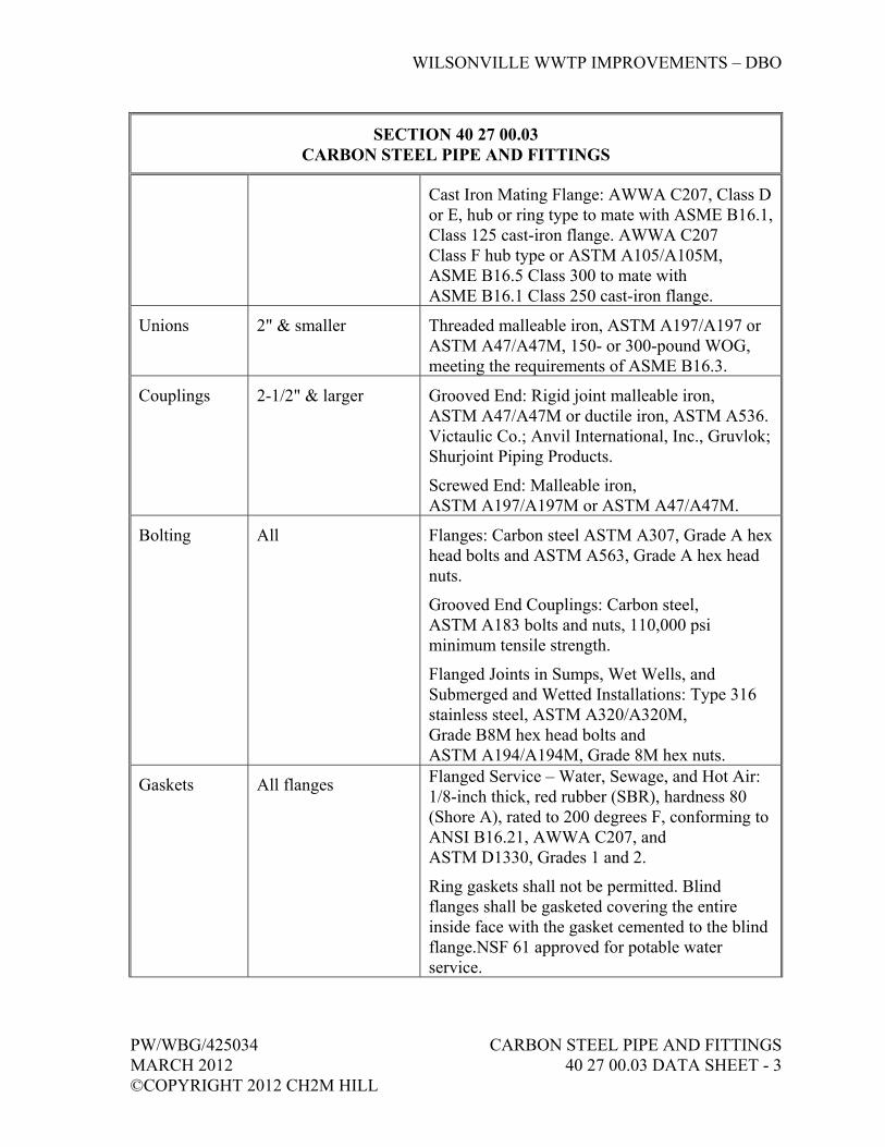
WILSONVILLE WWTP IMPROVEMENTS – DBO
PW/WBG/425034 CARBON STEEL PIPE AND FITTINGS MARCH 2012 40 27 00.03 DATA SHEET - 3 ©COPYRIGHT 2012 CH2M HILL
SECTION 40 27 00.03 CARBON STEEL PIPE AND FITTINGS
Cast Iron Mating Flange: AWWA C207, Class D or E, hub or ring type to mate with ASME B16.1, Class 125 cast-iron flange. AWWA C207 Class F hub type or ASTM A105/A105M, ASME B16.5 Class 300 to mate with ASME B16.1 Class 250 cast-iron flange.
Unions 2" & smaller Threaded malleable iron, ASTM A197/A197 or ASTM A47/A47M, 150- or 300-pound WOG, meeting the requirements of ASME B16.3.
Couplings 2-1/2" & larger Grooved End: Rigid joint malleable iron, ASTM A47/A47M or ductile iron, ASTM A536. Victaulic Co.; Anvil International, Inc., Gruvlok; Shurjoint Piping Products.
Screwed End: Malleable iron, ASTM A197/A197M or ASTM A47/A47M.
Bolting All Flanges: Carbon steel ASTM A307, Grade A hex head bolts and ASTM A563, Grade A hex head nuts.
Grooved End Couplings: Carbon steel, ASTM A183 bolts and nuts, 110,000 psi minimum tensile strength.
Flanged Joints in Sumps, Wet Wells, and Submerged and Wetted Installations: Type 316 stainless steel, ASTM A320/A320M, Grade B8M hex head bolts and ASTM A194/A194M, Grade 8M hex nuts.
Gaskets All flanges Flanged Service – Water, Sewage, and Hot Air: 1/8-inch thick, red rubber (SBR), hardness 80 (Shore A), rated to 200 degrees F, conforming to ANSI B16.21, AWWA C207, and ASTM D1330, Grades 1 and 2.
Ring gaskets shall not be permitted. Blind flanges shall be gasketed covering the entire inside face with the gasket cemented to the blind flange.NSF 61 approved for potable water service.

WILSONVILLE WWTP IMPROVEMENTS – DBO
CARBON STEEL PIPE AND FITTINGS PW/WBG/425034 40 27 00.03 DATA SHEET - 4 MARCH 2012 ©COPYRIGHT 2012 CH2M HILL
SECTION 40 27 00.03 CARBON STEEL PIPE AND FITTINGS
Thread Lubricant
2" & smaller General Service: 100 percent virgin PTFE Teflon tape.
Fuel Gas Service: Yellow Teflon tape designed for fuel gas service, Air Force A-A-58092, AA Thread Seal Tape, Inc.
END OF SECTION
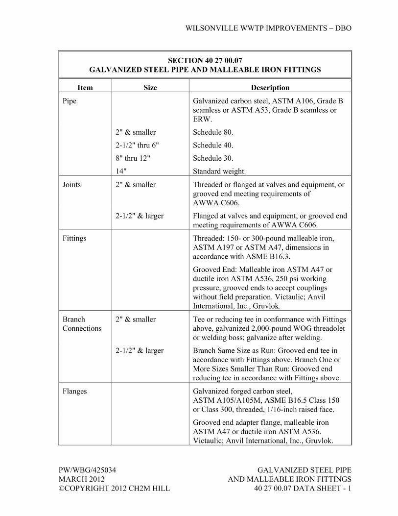
WILSONVILLE WWTP IMPROVEMENTS – DBO
PW/WBG/425034 GALVANIZED STEEL PIPE MARCH 2012 AND MALLEABLE IRON FITTINGS ©COPYRIGHT 2012 CH2M HILL 40 27 00.07 DATA SHEET - 1
SECTION 40 27 00.07 GALVANIZED STEEL PIPE AND MALLEABLE IRON FITTINGS
Item Size Description
Pipe Galvanized carbon steel, ASTM A106, Grade B seamless or ASTM A53, Grade B seamless or ERW.
2" & smaller
2-1/2" thru 6"
8" thru 12"
14"
Schedule 80.
Schedule 40.
Schedule 30.
Standard weight.
Joints 2" & smaller Threaded or flanged at valves and equipment, or grooved end meeting requirements of AWWA C606.
2-1/2" & larger Flanged at valves and equipment, or grooved end meeting requirements of AWWA C606.
Fittings Threaded: 150- or 300-pound malleable iron, ASTM A197 or ASTM A47, dimensions in accordance with ASME B16.3.
Grooved End: Malleable iron ASTM A47 or ductile iron ASTM A536, 250 psi working pressure, grooved ends to accept couplings without field preparation. Victaulic; Anvil International, Inc., Gruvlok.
Branch Connections
2" & smaller Tee or reducing tee in conformance with Fittings above, galvanized 2,000-pound WOG threadolet or welding boss; galvanize after welding.
2-1/2" & larger Branch Same Size as Run: Grooved end tee in accordance with Fittings above. Branch One or More Sizes Smaller Than Run: Grooved end reducing tee in accordance with Fittings above.
Flanges Galvanized forged carbon steel, ASTM A105/A105M, ASME B16.5 Class 150 or Class 300, threaded, 1/16-inch raised face.
Grooved end adapter flange, malleable iron ASTM A47 or ductile iron ASTM A536. Victaulic; Anvil International, Inc., Gruvlok.

WILSONVILLE WWTP IMPROVEMENTS – DBO
GALVANIZED STEEL PIPE PW/WBG/425034 AND MALLEABLE IRON FITTINGS MARCH 2012 40 27 00.07 DATA SHEET - 2 ©COPYRIGHT 2012 CH2M HILL
SECTION 40 27 00.07 GALVANIZED STEEL PIPE AND MALLEABLE IRON FITTINGS
Item Size Description
Unions Threaded malleable iron, ASTM A197 or ASTM A47, 300-pound WOG, brass to iron seat, meeting the requirements of ASME B16.3.
Couplings Grooved End: Rigid joint malleable iron, ASTM A47 or ductile iron, ASTM A536, 250 psi working pressure. Victaulic; Anvil International, Inc., Gruvlok.
Plugs Forged carbon steel, ASTM A181/A181M, Grade II, round head, threaded, galvanized.
Bolting Grooved End Couplings: Carbon steel, ASTM A183 bolts and nuts, 110,000 psi minimum tensile strength.
Flanges: Carbon steel ASTM A307, Grade A hex head bolts and ASTM A563, Grade A hex head nuts.
Gaskets All flanges Flanged, Water and Sewage Service: 1/8 inch thick, red rubber (SBR), hardness 80 (Shore A), rated to 200 degrees F, conforming to ASME B16.21, AWWA C207, and ASTM D1330, Grades 1 and 2.
Blind flanges shall be gasketed covering entire inside face with gasket cemented to blind flange.
Grooved end couplings
EPDM or chlorinated butyl per ASTM D2000 for water, and air to 230 degrees F, dimensions conforming to AWWA C606.
Thread Lubricant
2" & smaller Teflon tape or joint compound that is insoluble in water.
END OF SECTION
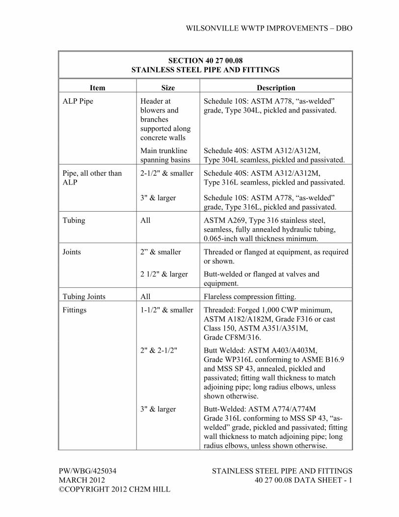
WILSONVILLE WWTP IMPROVEMENTS – DBO
PW/WBG/425034 STAINLESS STEEL PIPE AND FITTINGS MARCH 2012 40 27 00.08 DATA SHEET - 1 ©COPYRIGHT 2012 CH2M HILL
SECTION 40 27 00.08 STAINLESS STEEL PIPE AND FITTINGS
Item Size Description
ALP Pipe Header at blowers and branches supported along concrete walls
Schedule 10S: ASTM A778, “as-welded” grade, Type 304L, pickled and passivated.
Main trunkline spanning basins
Schedule 40S: ASTM A312/A312M, Type 304L seamless, pickled and passivated.
Pipe, all other than ALP
2-1/2" & smaller Schedule 40S: ASTM A312/A312M, Type 316L seamless, pickled and passivated.
3" & larger Schedule 10S: ASTM A778, “as-welded” grade, Type 316L, pickled and passivated.
Tubing All ASTM A269, Type 316 stainless steel, seamless, fully annealed hydraulic tubing, 0.065-inch wall thickness minimum.
Joints 2” & smaller Threaded or flanged at equipment, as required or shown.
2 1/2" & larger Butt-welded or flanged at valves and equipment.
Tubing Joints All Flareless compression fitting.
Fittings 1-1/2" & smaller Threaded: Forged 1,000 CWP minimum, ASTM A182/A182M, Grade F316 or cast Class 150, ASTM A351/A351M, Grade CF8M/316.
2" & 2-1/2" Butt Welded: ASTM A403/A403M, Grade WP316L conforming to ASME B16.9 and MSS SP 43, annealed, pickled and passivated; fitting wall thickness to match adjoining pipe; long radius elbows, unless shown otherwise.
3" & larger Butt-Welded: ASTM A774/A774M Grade 316L conforming to MSS SP 43, “as-welded” grade, pickled and passivated; fitting wall thickness to match adjoining pipe; long radius elbows, unless shown otherwise.
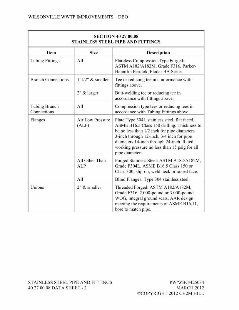
WILSONVILLE WWTP IMPROVEMENTS – DBO
STAINLESS STEEL PIPE AND FITTINGS PW/WBG/425034 40 27 00.08 DATA SHEET - 2 MARCH 2012 ©COPYRIGHT 2012 CH2M HILL
SECTION 40 27 00.08 STAINLESS STEEL PIPE AND FITTINGS
Item Size Description
Tubing Fittings All Flareless Compression Type Forged: ASTM A182/A182M, Grade F316, Parker-Hannifin Ferulok, Flodar BA Series.
Branch Connections 1-1/2" & smaller Tee or reducing tee in conformance with fittings above.
2" & larger Butt-welding tee or reducing tee in accordance with fittings above.
Tubing Branch Connections
All Compression type tees or reducing tees in accordance with Tubing Fittings above.
Flanges Air Low Pressure (ALP)
Plate Type 304L stainless steel, flat faced, ASME B16.5 Class 150 drilling. Thickness to be no less than 1/2 inch for pipe diameters 3-inch through 12-inch, 3/4 inch for pipe diameters 14-inch through 24-inch. Rated working pressure no less than 15 psig for all pipe diameters.
All Other Than ALP
Forged Stainless Steel: ASTM A182/A182M, Grade F304L, ASME B16.5 Class 150 or Class 300, slip-on, weld neck or raised face.
All Blind Flanges: Type 304 stainless steel.
Unions 2" & smaller Threaded Forged: ASTM A182/A182M, Grade F316, 2,000-pound or 3,000-pound WOG, integral ground seats, AAR design meeting the requirements of ASME B16.11, bore to match pipe.
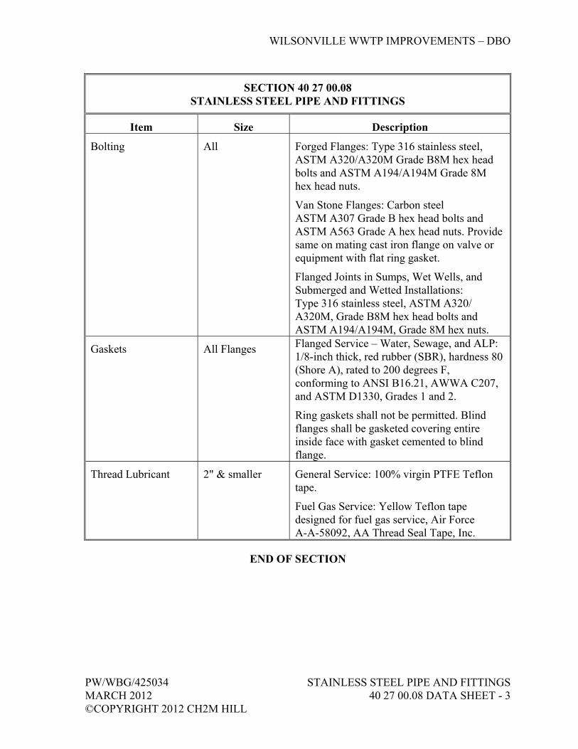
WILSONVILLE WWTP IMPROVEMENTS – DBO
PW/WBG/425034 STAINLESS STEEL PIPE AND FITTINGS MARCH 2012 40 27 00.08 DATA SHEET - 3 ©COPYRIGHT 2012 CH2M HILL
SECTION 40 27 00.08 STAINLESS STEEL PIPE AND FITTINGS
Item Size Description
Bolting All Forged Flanges: Type 316 stainless steel, ASTM A320/A320M Grade B8M hex head bolts and ASTM A194/A194M Grade 8M hex head nuts.
Van Stone Flanges: Carbon steel ASTM A307 Grade B hex head bolts and ASTM A563 Grade A hex head nuts. Provide same on mating cast iron flange on valve or equipment with flat ring gasket.
Flanged Joints in Sumps, Wet Wells, and Submerged and Wetted Installations: Type 316 stainless steel, ASTM A320/ A320M, Grade B8M hex head bolts and ASTM A194/A194M, Grade 8M hex nuts.
Gaskets All Flanges Flanged Service – Water, Sewage, and ALP: 1/8-inch thick, red rubber (SBR), hardness 80 (Shore A), rated to 200 degrees F, conforming to ANSI B16.21, AWWA C207, and ASTM D1330, Grades 1 and 2.
Ring gaskets shall not be permitted. Blind flanges shall be gasketed covering entire inside face with gasket cemented to blind flange.
Thread Lubricant 2" & smaller General Service: 100% virgin PTFE Teflon tape.
Fuel Gas Service: Yellow Teflon tape designed for fuel gas service, Air Force A-A-58092, AA Thread Seal Tape, Inc.
END OF SECTION


WILSONVILLE WWTP IMPROVEMENTS – DBO
PW/WBG/425034 POLYVINYL CHLORIDE (PVC) MARCH 2012 PIPE AND FITTINGS ©COPYRIGHT 2012 CH2M HILL 40 27 00.10 DATA SHEET - 1
SECTION 40 27 00.10 POLYVINYL CHLORIDE (PVC) PIPE AND FITTINGS
Item Size Description
General All Materials in contact with potable water shall conform to NSF 61 acceptance.
Pipe All Schedule 80 PVC: Type I, Grade I or Class 12454-B conforming to ASTM D1784 and ASTM D1785. Pipe shall be manufactured with titanium dioxide for ultraviolet protection.
Threaded Nipples: Schedule 80 PVC.
Fittings All Schedule to Match Pipe Above: ASTM D2466 and ASTM D2467 for socket weld type and Schedule 80 ASTM D2464 for threaded type. Fittings shall be manufactured with titanium dioxide for ultraviolet protection.
Joints All Solvent socket weld except where connection to threaded valves and equipment may require future disassembly.
Flanges All One piece, molded hub type PVC flat face flange in accordance with Fittings above, 125-pound ASME B16.1 drilling.
Bolting All Flat Face Mating Flange and In Corrosive Areas: ASTM A193/A193M, Type 316 stainless steel Grade B8M hex head bolts and ASTM A194/A194M Grade 8M hex head nuts.
With Raised Face Mating Flange: Carbon steel ASTM A307 Grade B square head bolts and ASTM A563 Grade A heavy hex head nuts.
Gaskets All Flat Face Mating Flange: Full faced 1/8-inch-thick ethylene propylene (EPR) rubber.
Raised Face Mating Flange: Flat ring 1/8-inch ethylene propylene (EPR) rubber, with filler gasket between OD of raised face and flange OD to protect the flange from bolting moment.

WILSONVILLE WWTP IMPROVEMENTS – DBO
POLYVINYL CHLORIDE (PVC) PW/WBG/425034 PIPE AND FITTINGS MARCH 2012 40 27 00.10 DATA SHEET - 2 ©COPYRIGHT 2012 CH2M HILL
SECTION 40 27 00.10 POLYVINYL CHLORIDE (PVC) PIPE AND FITTINGS
Item Size Description
Solvent Cement All Socket type joints shall be made employing solvent cement that meets or exceeds the requirements of ASTM D2564 and primer that meets or exceeds requirements of ASTM F656 and as recommended by pipe and fitting manufacturer, except solvent weld cement for PVC pipe joints in sodium hypochlorite service shall be free of silica filler and shall be certified by the manufacturer to be suitable for that service. Certification shall be submitted.
Thread Lubricant All Teflon Tape.
END OF SECTION
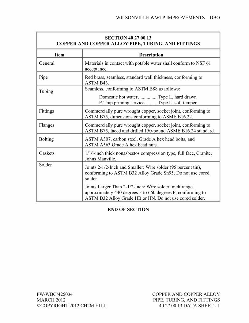
WILSONVILLE WWTP IMPROVEMENTS – DBO
PW/WBG/425034 COPPER AND COPPER ALLOY MARCH 2012 PIPE, TUBING, AND FITTINGS ©COPYRIGHT 2012 CH2M HILL 40 27 00.13 DATA SHEET - 1
SECTION 40 27 00.13 COPPER AND COPPER ALLOY PIPE, TUBING, AND FITTINGS
Item Description
General Materials in contact with potable water shall conform to NSF 61 acceptance.
Pipe Red brass, seamless, standard wall thickness, conforming to ASTM B43.
Tubing Seamless, conforming to ASTM B88 as follows:
Domestic hot water ................ Type L, hard drawn P-Trap priming service .......... Type L, soft temper
Fittings Commercially pure wrought copper, socket joint, conforming to ASTM B75, dimensions conforming to ASME B16.22.
Flanges Commercially pure wrought copper, socket joint, conforming to ASTM B75, faced and drilled 150-pound ASME B16.24 standard.
Bolting ASTM A307, carbon steel, Grade A hex head bolts, and ASTM A563 Grade A hex head nuts.
Gaskets 1/16-inch thick nonasbestos compression type, full face, Cranite, Johns Manville.
Solder Joints 2-1/2-Inch and Smaller: Wire solder (95 percent tin), conforming to ASTM B32 Alloy Grade Sn95. Do not use cored solder.
Joints Larger Than 2-1/2-Inch: Wire solder, melt range approximately 440 degrees F to 660 degrees F, conforming to ASTM B32 Alloy Grade HB or HN. Do not use cored solder.
END OF SECTION

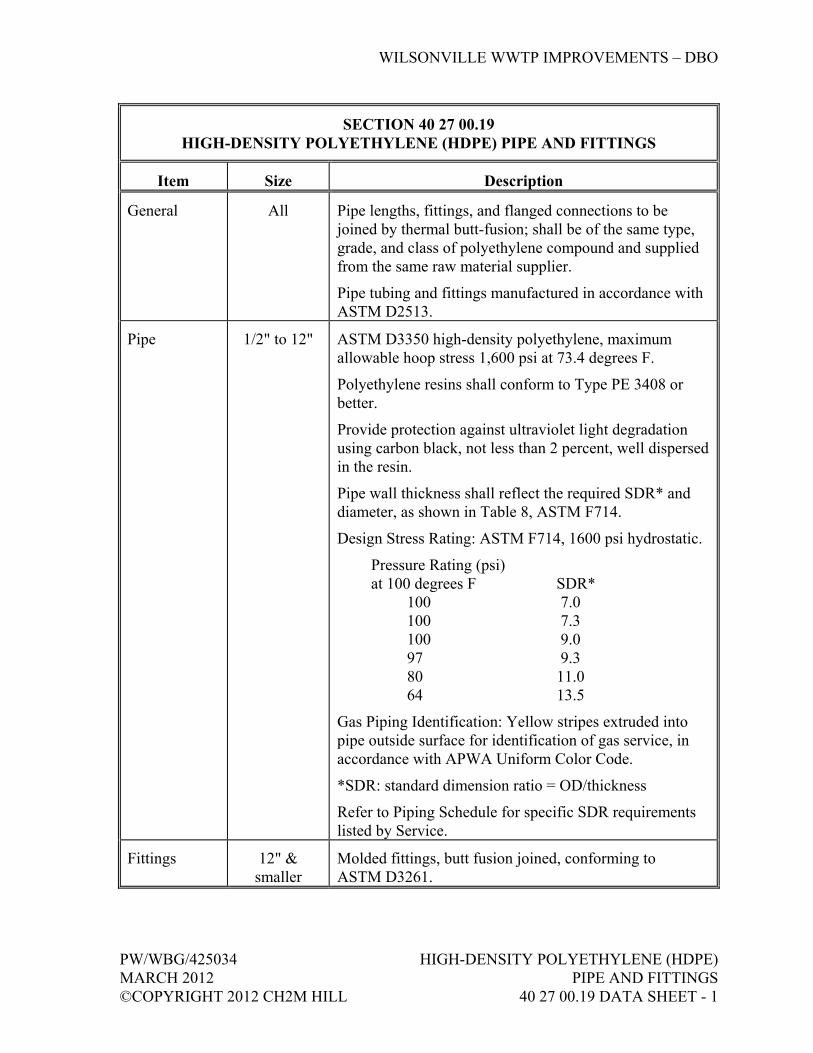
WILSONVILLE WWTP IMPROVEMENTS – DBO
PW/WBG/425034 HIGH-DENSITY POLYETHYLENE (HDPE) MARCH 2012 PIPE AND FITTINGS ©COPYRIGHT 2012 CH2M HILL 40 27 00.19 DATA SHEET - 1
SECTION 40 27 00.19 HIGH-DENSITY POLYETHYLENE (HDPE) PIPE AND FITTINGS
Item Size Description
General All Pipe lengths, fittings, and flanged connections to be joined by thermal butt-fusion; shall be of the same type, grade, and class of polyethylene compound and supplied from the same raw material supplier.
Pipe tubing and fittings manufactured in accordance with ASTM D2513.
Pipe 1/2" to 12" ASTM D3350 high-density polyethylene, maximum allowable hoop stress 1,600 psi at 73.4 degrees F.
Polyethylene resins shall conform to Type PE 3408 or better.
Provide protection against ultraviolet light degradation using carbon black, not less than 2 percent, well dispersed in the resin.
Pipe wall thickness shall reflect the required SDR* and diameter, as shown in Table 8, ASTM F714.
Design Stress Rating: ASTM F714, 1600 psi hydrostatic.
Pressure Rating (psi) at 100 degrees F SDR*
100 7.0 100 7.3 100 9.0 97 9.3 80 11.0 64 13.5
Gas Piping Identification: Yellow stripes extruded into pipe outside surface for identification of gas service, in accordance with APWA Uniform Color Code.
*SDR: standard dimension ratio = OD/thickness
Refer to Piping Schedule for specific SDR requirements listed by Service.
Fittings 12" & smaller
Molded fittings, butt fusion joined, conforming to ASTM D3261.
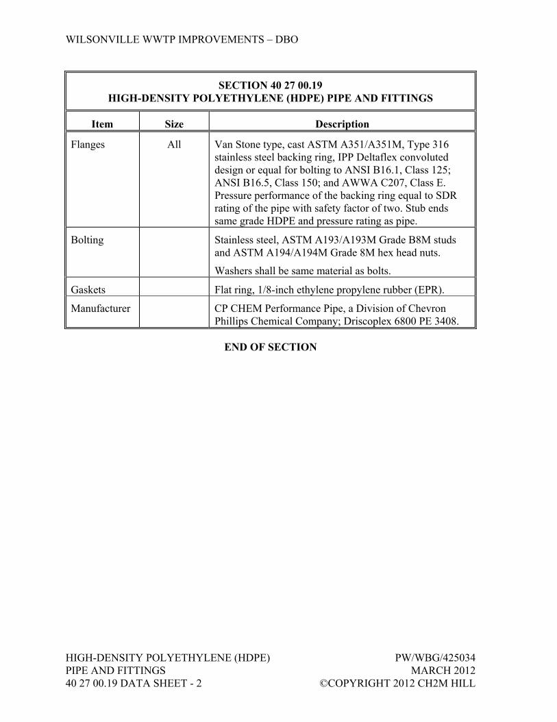
WILSONVILLE WWTP IMPROVEMENTS – DBO
HIGH-DENSITY POLYETHYLENE (HDPE) PW/WBG/425034 PIPE AND FITTINGS MARCH 2012 40 27 00.19 DATA SHEET - 2 ©COPYRIGHT 2012 CH2M HILL
SECTION 40 27 00.19 HIGH-DENSITY POLYETHYLENE (HDPE) PIPE AND FITTINGS
Item Size Description
Flanges All Van Stone type, cast ASTM A351/A351M, Type 316 stainless steel backing ring, IPP Deltaflex convoluted design or equal for bolting to ANSI B16.1, Class 125; ANSI B16.5, Class 150; and AWWA C207, Class E. Pressure performance of the backing ring equal to SDR rating of the pipe with safety factor of two. Stub ends same grade HDPE and pressure rating as pipe.
Bolting Stainless steel, ASTM A193/A193M Grade B8M studs and ASTM A194/A194M Grade 8M hex head nuts.
Washers shall be same material as bolts.
Gaskets Flat ring, 1/8-inch ethylene propylene rubber (EPR).
Manufacturer CP CHEM Performance Pipe, a Division of Chevron Phillips Chemical Company; Driscoplex 6800 PE 3408.
END OF SECTION

WILSONVILLE WWTP IMPROVEMENTS – DBO
PW/WBG/425034 PROFILE WALL MARCH 2012 POLYETHYLENE (PWPE) ©COPYRIGHT 2012 CH2M HILL 40 27 00.21 DATA SHEET - 1
SECTION 40 27 00.21 PROFILE WALL POLYETHYLENE (PWPE)
Item Description
Pipe AASHTO MP6 (1050- to 1200-mm diameter), as manufactured by ADS, or equal.
ASTM F894, PE3408 profile wall type pipe (Spirolite, or equal), class 63, unless otherwise specified.
Provide magnetic tracer tape.
Profile Type S and D.
Extruded ribs for gaining structural rigidity and strength.
Joints Bell and spigot, gasketed type. Gaskets per ASTM F477.
Flanges: Flange dimensions and bolt pattern as called out on Drawings. Flanged adapters butt-fused to pipe for dampers or valves or where called out on Drawings, AWWA C207. Stainless steel backup ring epoxy coated. Flange gasket to be 1/4-inch compressed Kevlar with neoprene binder flange gasket. Flanged adapter may be butt-fusion welded to solid wall pipe for attaching to profile wall pipe. Interior of pipe to remain smooth (no step down) at any transitions.
Fittings Manufacturer’s standard; same stiffness and class as adjacent pipe.
Where mitered elbows are provided, interior of fitting shall remain smooth. Trim any residual material as necessary. Provide double mitered as a minimum, unless otherwise noted.
Source Quality Control In accordance with specified AASHTO Specification.
Flexible Connections Neoprene with coated stainless steel clamps, 1/2-inch thick.
Remarks:
1. Connections to stainless steel or FRP ductwork shall be made with flanged connections. Flange dimensions and bolt pattern shall match.
2. Manufacture from materials that meet or exceed the requirements of ASTM D3350-04 for a minimum cell classification of PE 345434C.

WILSONVILLE WWTP IMPROVEMENTS – DBO
PROFILE WALL PW/WBG/425034 POLYETHYLENE (PWPE) MARCH 2012 40 27 00.21 DATA SHEET - 2 ©COPYRIGHT 2012 CH2M HILL
SECTION 40 27 00.21 PROFILE WALL POLYETHYLENE (PWPE)
Item Description
3. Place bells facing upstream. Locate bell and spigot joints, pushed home, at each structural joint indicated on Drawings.
4. Moe miter, minimum, per 45 degrees of deflection.
5. For bell and spigot connections, provide a minimum of two bell and spigot joints pulled 1-5/8 inches out from the home position for each 40 feet of pipe length.
6. Where joining of profile wall pipe by extrusion welding, all joints shall be performed by factory trained technicians.
END OF SECTION
WILSONVILLE WWTP IMPROVEMENTS – DBO
PW/WBG/425034 PROCESS PIPING SPECIALTIES MARCH 2012 40 27 01 - 1 ©COPYRIGHT 2012 CH2M HILL
SECTION 40 27 01 PROCESS PIPING SPECIALTIES
PART 1 GENERAL
1.01 RELATED SECTIONS
A. Related sections include the following:
1. Division 1, General Requirements. 2. Section 03 30 00, Cast-in-Place Concrete. 3. Section 09 90 00, Painting and Coating. 4. Section 40 05 15, Piping Support Systems. 5. Section 40 27 00, Process Piping—General. 6. Section 40 27 00.01, Cement-Mortar or Glass-Lined Ductile Iron Pipe
and Fittings. 7. Section 40 27 02, Process Valves and Operators. 8. Section 40 91 00, Instrumentation Components.
1.02 REFERENCES
A. The following is a list of standards which may be referenced in this Section:
1. American Society of Mechanical Engineers (ASME): a. B16.1, Gray Iron Pipe Flanges and Flanged Fittings. b. B16.5, Pipe Flanges and Flanged Fittings: NPS 1/2 through
NPS 24. 2. American Water Works Association (AWWA):
a. C153/A21.53, Ductile-Iron Compact Fittings for Water Service. b. C210, Liquid-Epoxy Coating Systems for the Interior and Exterior
of Steel Water Pipelines. c. C213, Fusion-Bonded Epoxy Coating for the Interior and Exterior
of Steel Water Pipelines. d. C219, Bolted, Sleeve-Type Couplings for Plain-End Pipe. e. Manual M11, Steel Pipe—A Guide for Design and Installation.
3. ASTM International (ASTM): a. A153/A153M, Standard Specification for Zinc Coating (Hot-Dip)
on Iron and Steel Hardware. b. A276, Standard Specification for Stainless Steel Bars and Shapes.
4. National Fire Protection Association (NFPA): 24, Standard for the Installation of Private Fire Service Mains and Their Appurtenances.
5. NSF International (NSF): NSF 61, Drinking Water System Components—Health Effects.
WILSONVILLE WWTP IMPROVEMENTS – DBO
PROCESS PIPING SPECIALTIES PW/WBG/425034 40 27 01 - 2 MARCH 2012 ©COPYRIGHT 2012 CH2M HILL
1.03 SUBMITTALS
A. Action Submittals: Manufacturer’s data on materials, construction, end connections, ratings, overall lengths, and live lengths (as applicable).
B. Informational Submittals:
1. Basket Strainer: a. Manufacturer’s written/printed installation instructions. b. Manufacturer’s Certificate of Proper Installation as specified in
Section 01 43 33, Manufacturers’ Field Services. 2. Operation and Maintenance Data as specified in Section 01 78 23,
Operation, Maintenance, and Asset Data.
PART 2 PRODUCTS
2.01 GENERAL
A. Provide required piping specialty items, whether shown or not shown on Drawings, as required by applicable codes and standard industry practice.
B. Rubber ring joints, mechanical joints, flexible couplings, and proprietary restrained ductile iron pipe joints are considered flexible joints; welded, screwed, and flanged pipe joints are not considered flexible.
2.02 FLEXIBLE CONNECTORS
A. Teflon Flexible Connector:
1. Use: Where required for nonmetallic piping connections to pumps or equipment.
2. Type: Expansion joint, two convolutions, unless otherwise shown, with metal reinforcing bands.
3. Flanges: Ductile iron, drilled 150 psi ASME B16.5 standard. 4. Working Pressure Rating: 140 psi, minimum, at 120 degrees F. 5. Thrust Restraint: Limit bolts to restrain force developed by specified
test pressure. 6. Manufacturers and Products:
a. Garlock; Style 214. b. Resistoflex; No. R6904. c. Unisource Manufacturing, Inc.; Style 112. d. Proco Products, Inc.; Series 442.

WILSONVILLE WWTP IMPROVEMENTS – DBO
PW/WBG/425034 PROCESS PIPING SPECIALTIES MARCH 2012 40 27 01 - 3 ©COPYRIGHT 2012 CH2M HILL
B. Elastomer Flexible Connector:
1. Use: Where shown on Drawings specifically for ALP service, and where required for piping connections to pumps or equipment.
2. ALP Service Conditions: a. Maximum Operating Temperature: 200 degrees F. b. Normal Operating Temperature: 150 degrees F. c. Minimum Operating Temperature: 100 degrees F. d. Maximum Ambient Temperature: 110 degrees F. e. Minimum Ambient Temperature: 10 degrees F. f. Maximum Operating Pressure: 18 psi. g. Normal Operating Pressure: 15 psi.
3. Type: Expansion joint, fabricated spool, single filled arch. 4. Materials: Nitrile tube and wrap-applied neoprene cover. 5. End Connections: Flanged, drilled 125-pound ASME B16.1 standard,
with full elastomer face and steel retaining rings. 6. Washers: Over retaining rings to help provide leak-proof joint under test
pressure. 7. Thrust Restraint: Control rods to limit travel of elongation and
compression. 8. Bellows Arch Lining: EPDM. 9. Rated Temperature: 250 degrees F. 10. Rated Deflection and Pressure:
a. Lateral Deflection: 3/4-inch, minimum. b. Burst Pressure: Four times the working pressure. c. Compression deflection and minimum working pressure as
follows:
Size (inch)
Deflection (inch)
Pressure (psig)
2-1/2 to 12 1.06 150
14 1.65 130
16 to 20 1.65 110
11. Manufacturers and Products: a. Proco Products, Inc.; Series 230. b. Unisource Manufacturing, Inc.; Style 1500.
C. Bronze Flexible Metal Hose Connector:
1. Use: Where required for piping connections to equipment. 2. Type: Close pitch, annular corrugated with single braided jacket. 3. Material: Bronze.
WILSONVILLE WWTP IMPROVEMENTS – DBO
PROCESS PIPING SPECIALTIES PW/WBG/425034 40 27 01 - 4 MARCH 2012 ©COPYRIGHT 2012 CH2M HILL
4. End Connections: Female copper solder joint. 5. Minimum Burst Pressure: 500 psig at 70 degrees F. 6. Length: Minimum manufacturer recommendation for vibration
isolation. 7. Manufacturers:
a. Senior Flexonics. b. Unisource Manufacturing, Inc.
D. Stainless Steel Flexible Metal Hose Connector:
1. Use: Where required for piping connections to pumps or equipment. 2. Type: Close pitch, annular corrugated with double braided jacket. 3. Material: Type 304 stainless steel hose, 300 Series stainless steel braid. 4. End Connections: ANSI B16.5 Class 150 or Class 300, slip-on flanges
as required for piping system. 5. Rated Working Pressure: 430 at 70 degrees F. 6. Length: 16-inch face to face. 7. Manufacturer and Product: Unisource Manufacturing, Inc.; SF22.
E. Concrete Closure Collar: As specified in Section 03 30 00, Cast-in-Place Concrete.
2.03 COUPLINGS
A. General:
1. Coupling linings for use in potable water systems shall be in conformance with NSF 61.
2. Couplings shall be rated for working pressure not less than indicated in Piping Schedule for the service and not less than 150 psi.
3. Couplings shall be lined and coated with fusion-bonded epoxy in accordance with AWWA C213.
4. Unless thrust restraint is provided by other means, couplings shall be harnessed in accordance with requirements of AWWA Manual M11, and restrained with retainer bar or ring welded to pipe end, or as shown on Drawings.
5. Sleeve type couplings shall conform to AWWA C219 and shall be hydraulically expanded beyond minimum yield for accurate sizing and proofing of tensile strength.
B. Expansion Coupling:
1. Use: Only as required on a case-by-case basis, as an alternate to flanged-end elastomer flexible connector, for ALP service only.

WILSONVILLE WWTP IMPROVEMENTS – DBO
PW/WBG/425034 PROCESS PIPING SPECIALTIES MARCH 2012 40 27 01 - 5 ©COPYRIGHT 2012 CH2M HILL
Locations shall be approved by CH2M HILL prior to purchase and installation of couplings.
2. Service Conditions: a. Maximum Operating Temperature: 200 degrees F. b. Normal Operating Temperature: 150 degrees F. c. Minimum Operating Temperature: 100 degrees F. d. Maximum Ambient Temperature: 110 degrees F. e. Minimum Ambient Temperature: 10 degrees F. f. Maximum Operating Pressure: 18 psi. g. Normal Operating Pressure: 15 psi.
3. Movement: a. Normal Axial Expansion/Contraction: 1/2 inch. b. Maximum Allowable Axial Expansion/Contraction: 1 inch. c. Normal Lateral Deflection: 0 degrees. d. Maximum Allowable Lateral Deflection: 1 degree.
4. Materials: a. Body: Type 316L stainless steel. b. Type 2 Reinforced Closure Slip Pipe Cladding: Type 316L
stainless steel, factory welded. c. O-Ring Gaskets: Silicone, rated to 350 degrees F. d. Bolts and Nuts: Type 316 stainless steel.
5. Manufacturer and Product: Victaulic Co.; Depend-O-Lok, Model FxE.
C. Flexible Sleeve Type Coupling:
1. Manufacturers and Products: a. Steel Pipe:
1) Dresser Piping Specialties; Style 38. 2) Smith-Blair, Inc.; Style 411.
b. Ductile Iron Pipe: 1) Dresser Piping Specialties; Style 253. 2) Smith-Blair, Inc.; Style 411.
D. Flange Coupling Adapter (Restrained):
1. Pressure Rating: a. Minimum Working Pressure Rating: Not less than 150 psi. b. Safety Factor: Not less than two times working pressure and shall
be supported by manufacturer’s proof testing. 2. Thrust Restraint:
a. Provide hardened steel wedges that bear against and engage outer pipe surface, and allow articulation of pipe joint after assembly while wedges remain in their original setting position on pipe surface.

WILSONVILLE WWTP IMPROVEMENTS – DBO
PROCESS PIPING SPECIALTIES PW/WBG/425034 40 27 01 - 6 MARCH 2012 ©COPYRIGHT 2012 CH2M HILL
b. Products employing set screws that bear directly on pipe will not be acceptable.
3. Gasket material shall be EPDM, rated for 250 degrees F or greater, at the solids dryer and dryer condensate system piping. Gasket material SBR, rated for 180 degrees F or greater, is acceptable for all other services.
4. Manufacturer and Product: EBAA Iron Sales Co.; Mega-Flange.
E. Dismantling Joint:
1. Pressure Rating: a. Minimum working pressure rating shall not be less than rating of
the connecting flange. b. Proof testing shall conform to requirements of AWWA C219 for
bolted couplings. 2. Manufacturers and Products:
a. Dresser Piping Specialties; Style 131. b. Viking Johnson.
F. Exposed Metallic Piping Plain End Coupling:
1. Plain end pipe couplings shall be self-restrained against hydrostatic thrust forces equal to not less than two times the working pressure rating of the coupling. Couplings shall accommodate 4 degrees angular deflection at the time of installation and subsequent to pressurization.
2. Casing, bolts, and nuts shall be Type 304 or Type 316 stainless steel. The sealing sleeve shall be silicone.
3. Manufacturer and Product: Straub Couplings; Grip-L or Metal Grip.
G. Quick Connect Coupling:
1. Type: Twin cam arm actuated, male and female, locking, for general non-chemical services.
2. Materials: Stainless steel with Teflon-silicone gasket, unless otherwise indicated, or as recommended by the manufacturer for specific service.
3. End Connections: NPT threaded or flanged to match piping connections.
4. Plugs and Caps: Female dust cap for each male end; male dust plug for each female end.
5. Pressure Rating: 125 psi, minimum, at 70 degrees F. 6. Manufacturer and Product: OPW; Kamlock 633 or 733.

WILSONVILLE WWTP IMPROVEMENTS – DBO
PW/WBG/425034 PROCESS PIPING SPECIALTIES MARCH 2012 40 27 01 - 7 ©COPYRIGHT 2012 CH2M HILL
2.04 BELLOWS
A. Teflon Bellows:
1. Use: Where required for piping connections. 2. Type: Three convolutions, with metal reinforcing bands. 3. Flanges: Ductile iron, drilled 150 psi ASME B16.5 standard. 4. Working Pressure Rating: 100 psig, minimum, at 120 degrees F. 5. Thrust Restraint: Limit bolts to restrain force developed by specified
test pressure. 6. Manufacturers and Products:
a. Unisource Manufacturing, Inc.; Style 113, b. Proco Products, Inc.; Series 443.
B. Copper Pipe Expansion Compensator:
1. Material: Stainless steel bellows with female copper solder joint ends. 2. Working Pressure Rating: 175 psig, minimum. 3. Accessories: Anti-torque device to protect bellows. 4. Manufacturers and Products:
a. Senior Flexonics; Model HB. b. Hyspan; Model 8510. c. Unisource Manufacturing, Inc.; Style EC-FFS.
C. Galvanized and Black Steel Pipe Expansion Compensator:
1. Material: Carbon steel with stainless steel bellows. 2. Working Pressure Rating: 175 psig, minimum. 3. Accessories: Anti-torque device to protect bellows. 4. Manufacturers and Products:
a. Senior Flexonics; Model H. b. Hyspan; Model 8503. c. Unisource Manufacturing, Inc.; Style EC-MMT.
D. Flexible Metal Hose:
1. Type: Close pitch, annular corrugated with single braided jacket. 2. Material: Stainless steel, ASTM A276, Type 321. 3. End Connections:
a. 3 Inches and Larger: Shop fabricated flanged ends to match mating flanges.
b. 2-1/2 Inches and Smaller: Screwed ends with one union end. 4. Minimum Burst Pressure: 600 psig at 70 degrees F for 12 inches and
smaller. 5. Length: Provide hose live-length equal to lengths shown on Drawings.

WILSONVILLE WWTP IMPROVEMENTS – DBO
PROCESS PIPING SPECIALTIES PW/WBG/425034 40 27 01 - 8 MARCH 2012 ©COPYRIGHT 2012 CH2M HILL
6. Manufacturers: a. Senior Flexonics; Series 401M. b. Anamet Industrial, Inc.; BWC21-1.
2.05 SEAL WATER SETS
A. Provide pump seal water sets where pumps are specified with external flush and as shown on the Drawings.
B. Seal water sets shall be complete with isolation valves, throttling valves (needle valves), strainers, pressure regulating valves, pressure gauges, and sight flow indicators. The component arrangements shall be as shown in the seal water piping details or as recommended by pump manufacturer.
C. Seal Water Set Components:
1. Isolations Valve: Valve Type V306 as specified in Section 40 27 02, Process Valves and Operators.
2. Needle Valve: Valve Type V208 as specified in Section 40 27 02, Process Valves and Operators.
3. Solenoid Valve: Valve Type V940 as specified in Section 40 27 02, Process Valves and Operators.
4. Pressure Control Valve Type V711 as specified in Section 40 27 02, Process Valves and Operators.
5. Strainer: Water service as specified herein. 6. Low Pressure Switch: As specified in Section 40 91 00, Instrumentation
Components. 7. Pressure Gauge:
a. Construction: 3-1/2-inch case size, 0 to 60 psi range, steel case, glass crystal, brass movement, and 1/4-inch NPT lower connection.
b. Furnish with 1/4-inch stainless steel gauge cock. c. Manufacturers and Products:
1) Ashcroft; Type 1008. 2) Marsh; J80.
8. Sight Flow Indicators: a. Stainless steel, 3/8-inch, horizontal, ball action with tempered
glass. b. Rated 125 psi with NPT screwed ends. c. Operate with a minimum flow of 0.25 gpm. d. Manufacturers and Products:
1) Eugene Ernst Co.; Series E-57-4. 2) Jacoby Tarbox Co.

WILSONVILLE WWTP IMPROVEMENTS – DBO
PW/WBG/425034 PROCESS PIPING SPECIALTIES MARCH 2012 40 27 01 - 9 ©COPYRIGHT 2012 CH2M HILL
9. Seal Water Hose: a. Hose shall be 3/8-inch, stainless steel, braided. Rated minimum
working pressure of 200 psi. b. Manufacturers:
1) Senior Flexonics. 2) Unisource Manufacturing, Inc.
2.06 SERVICE SADDLES
A. Double-Strap Iron:
1. Pressure Rating: Capable of withstanding 150 psi internal pressure without leakage or over stressing.
2. Run Diameter: Compatible with outside diameter of pipe on which saddle is installed.
3. Taps: Iron pipe threads. 4. Materials:
a. Body: Malleable or ductile iron. b. Straps: Galvanized steel. c. Hex Nuts and Washers: Steel. d. Seal: Rubber.
5. Manufacturers and Products: a. Smith-Blair; Series 313 or 366. b. Dresser; Style 91.
B. Single-Strap Iron:
1. Pressure Rating: Capable of withstanding 150 psi internal pressure without leakage or over stressing.
2. Run Diameter: Compatible with outside diameter of pipe on which saddle is installed.
3. Taps: Iron pipe threads. 4. Pipe and tap sizes as shown on Drawings. 5. Materials:
a. Body: Malleable or ductile iron. b. Straps: Galvanized steel. c. Hex Nuts and Washers: Steel. d. Seal: Rubber.
6. Manufacturers and Products: a. Smith-Blair; Series 311. b. Or approved equal.
WILSONVILLE WWTP IMPROVEMENTS – DBO
PROCESS PIPING SPECIALTIES PW/WBG/425034 40 27 01 - 10 MARCH 2012 ©COPYRIGHT 2012 CH2M HILL
C. Nylon-Coated Iron:
1. Pressure Rating: Capable of withstanding 150 psi internal pressure without leakage or over stressing.
2. Run Diameter: Compatible with outside diameter of pipe on which saddle is installed.
3. Materials: a. Body: Nylon-coated iron. b. Seal: Buna-N. c. Clamps and Nuts: Stainless steel.
4. Manufacturer: Smith-Blair; Style 315 or 317.
D. Saddle Tap: Provide saddle tap, tapped saddle, or tapped outlet as a standard ductile iron pipe fitting in accordance with Section 40 27 00, Process Piping—General, and Section 40 27 00.01, Cement-Mortar or Glass-Lined Ductile Iron Pipe and Fittings.
2.07 PIPE SLEEVES
A. Steel Pipe Sleeve:
1. Minimum Thickness: 1/4 inch. 2. Seep Ring:
a. Center steel flange for water stoppage on sleeves in exterior or water-bearing walls, 3/16-inch minimum thickness.
b. Outside Diameter: Unless otherwise shown, 3 inches greater than pipe sleeve outside diameter.
c. Continuously fillet weld on each side all around. 3. Factory Finish:
a. Galvanizing: 1) Hot-dip applied, meeting requirements of
ASTM A153/A153M. 2) Electroplated zinc or cadmium plating is unacceptable.
b. Shop Lining and Coating: Factory prepare, prime, and finish coat in accordance with Section 09 90 00, Painting and Coating.
B. Molded Polyethylene Pipe Sleeve:
1. Molded HDPE with integral water stop ring not less than 3 inches larger than sleeve.
2. Provided with end caps for support during concrete placement. 3. Manufacturer and Product: Century-Line; Model CS sleeves as
manufactured by PSI-Thunderline/Link-Seal.

WILSONVILLE WWTP IMPROVEMENTS – DBO
PW/WBG/425034 PROCESS PIPING SPECIALTIES MARCH 2012 40 27 01 - 11 ©COPYRIGHT 2012 CH2M HILL
C. Insulated and Encased Pipe Sleeve:
1. Manufacturer and Product: Pipe Shields, Inc.; Models WFB, WFB-CS and -CW Series, as applicable.
D. Modular Mechanical Seal:
1. Type: Interconnected synthetic rubber links shaped and sized to continuously fill annular space between pipe and wall sleeve opening.
2. Fabrication: a. Assemble interconnected rubber links with ASTM A276,
Type 316 stainless steel bolts and nuts. b. Pressure plates shall be reinforced nylon polymer.
3. Size: According to manufacturer’s instructions for size of pipes shown to provide a watertight seal between pipe and wall sleeve opening, and to withstand a hydrostatic head of 40 feet of water.
4. Manufacturer: Thunderline Corp., Link-Seal Division.
2.08 SLAB, FLOOR, WALL AND ROOF PENETRATIONS
A. Ductile Iron Wall Pipe:
1. Diameter and Ends: Same as connecting ductile iron pipe. 2. Thickness: Equal to or greater than remainder of pipe in line. 3. Fittings: In accordance with applicable Pipe Data Sheet. 4. Thrust Collars:
a. Where required at specific locations on Drawings. b. Rated for thrust load developed at 250 psi. c. Safety Factor: Two, minimum. d. Material and Construction: Ductile iron or cast iron, cast integral
with wall pipe wherever possible, or thrust rated, welded attachment to wall pipe.
5. Manufacturers: a. American Cast Iron Pipe Co. b. U.S. Pipe and Foundry Co.
B. Steel or Stainless Steel Wall Pipe:
1. Same material and thickness as connecting pipe, except 1/4-inch minimum thickness.
2. Lining: Same as connecting pipe. 3. Thrust Collar:
a. Where required at specific locations on Drawings.
WILSONVILLE WWTP IMPROVEMENTS – DBO
PROCESS PIPING SPECIALTIES PW/WBG/425034 40 27 01 - 12 MARCH 2012 ©COPYRIGHT 2012 CH2M HILL
b. Outside Diameter: Unless otherwise shown, 3 inches greater than outside diameter of wall pipe.
c. Continuously fillet welded on each side all around.
2.09 MISCELLANEOUS SPECIALTIES
A. Strainer, Water Service, 2 Inches and Smaller:
1. Type: Bronze body, Y-pattern, 200 psi nonshock rated, with screwed gasketed bronze cap.
2. Screen: Heavy-gauge Type 304 stainless steel or monel, 20-mesh. 3. Manufacturers and Products:
a. Armstrong International; Inc.; Model F. b. Mueller Steam Specialty; Model 351M.
B. Strainer, Water Service, 2-1/2 Inches and Larger:
1. Type: Cast iron or ductile iron body, Y-pattern, 175 psi nonshock rated, with flanged gasketed iron cap.
2. Screen: Heavy-gauge Type 316 stainless steel, 0.045-inch perforations. 3. Manufacturers and Products:
a. Armstrong International, Inc.; Model A7FL 125. b. Mueller Steam Specialty; Model 751.
C. Strainer, Plastic Piping Systems, 4 Inches and Smaller:
1. Type: Y-pattern PVC body, 150 psi nonshock rated, with screwed PVC cap and Viton seals.
2. End Connections: Screwed or solvent weld, 2 inches and smaller. Class 150 ANSI flanged, 2-1/2 inches and larger.
3. Screen: Heavy-gauge PVC, 1/32-inch mesh, minimum 2 to 1 screen area to pipe size ratio.
4. Manufacturer: Hayward.
D. PVC Duplex Basket Strainer:
1. Furnish units meeting the performance and design requirements as outlined below: a. Double chamber design, body shall be PVC with threaded hand
removable cover. b. Strainer shall include 125-pound ANSI flanges. c. Provide a 1/16-inch perforated PVC basket. d. Strainers to be provided with PTFE O-ring seals. e. Strainers shall be fitted with threaded drain plug.
WILSONVILLE WWTP IMPROVEMENTS – DBO
PW/WBG/425034 PROCESS PIPING SPECIALTIES MARCH 2012 40 27 01 - 13 ©COPYRIGHT 2012 CH2M HILL
f. Basket strainer shall be pressure rated at 150 psi for water at 73 degrees F.
g. Inlet and Outlet Valves: Lever operated swing type valve disc with PTFE disc seals.
h. Permit one basket strainer to be removed for cleaning while other basket is in operation.
2. Materials, equipment, and accessories specified in this Section shall be products of: a. Hayward Strainers, Inc. b. Spears. c. No substitutions allowed.
E. PVC Simplex Basket Strainer:
1. Furnish unit meeting the performance and design requirements as outlined below: a. Single chamber design, body shall be PVC with threaded hand
removable cover. b. Strainer shall include 125-pound ANSI flanges. c. Provide a 1/16-inch perforated PVC basket. d. Strainer to be provided with PTFE O-ring seals. e. Strainer shall be fitted with threaded drain plug. f. Strainer shall be pressure rated at 150 psi for water at
73 degrees F. g. Inlet and Outlet Valves: Lever operated swing type valve disc
with PTFE disc seals. 2. Materials, equipment, and accessories specified in this Section shall be
products of: a. Hayward Strainers, Inc. b. Spears. c. No substitutions allowed.
F. Spray Nozzle, Type 1:
1. Locations and quantities as indicated on Drawings. 2. Flat spray pattern, 3.5 gpm capacity, spray angle 65 degrees at 40 psi. 3. Type 303 stainless steel, 1/2-inch NPT male connection. 4. Manufacturer and Product: Spraying Systems Co.; VeeJet,
Model H1/2U-SS6570.
G. Spray Nozzle, Type 2:
1. Locations and quantities as indicated on Drawings. 2. Flat spray pattern, 15 gpm capacity, spray angle 80 degrees at 40 psi. 3. Type 303 stainless steel, 1/2-inch NPT male connection.
WILSONVILLE WWTP IMPROVEMENTS – DBO
PROCESS PIPING SPECIALTIES PW/WBG/425034 40 27 01 - 14 MARCH 2012 ©COPYRIGHT 2012 CH2M HILL
4. Manufacturer and Product: Spraying Systems Co.; VeeJet, Model H1/2U-SS80150.
H. Quenching Spray Nozzle:
1. Location: Facility 78 Dewatering and Drying Building Loadout Room. 2. Quantity: 3. 3. Full cone spray pattern, 14.3 gpm capacity, spray angle 60 degrees at
60 psi. 4. Type 316 stainless steel, 3/4-inch, NPT male connection. 5. Manufacturer and Product: Spraying Systems Co.; FullJet,
Model 3/4HHMFP – 316SS 60 70.
PART 3 EXECUTION
3.01 GENERAL
A. Provide accessibility to piping specialties for control and maintenance.
3.02 PIPING FLEXIBILITY PROVISIONS
A. General:
1. Thrust restraint shall be provided as specified in Section 40 27 00, Process Piping—General.
2. Install flexible couplings to facilitate piping installation, in accordance with approved Shop Drawings.
B. Flexible Joints at Concrete Backfill or Encasement: Install within 18 inches or one-half pipe diameter, whichever is less, from the termination of any concrete backfill or concrete encasement.
C. Flexible Joints at Concrete Structures:
1. Install 18 inches or less from face of structures; joint may be flush with face.
2. Where shown, install a second flexible joint as follows: a. Pipe Diameter 18 Inches and Smaller: Within 18 inches of first
joint. b. Pipe Diameter Larger than 18 Inches: Within one pipe diameter of
first joint.

WILSONVILLE WWTP IMPROVEMENTS – DBO
PW/WBG/425034 PROCESS PIPING SPECIALTIES MARCH 2012 40 27 01 - 15 ©COPYRIGHT 2012 CH2M HILL
3.03 PIPING TRANSITION
A. Applications:
1. Provide complete closure assembly where pipes meet other pipes or structures.
2. Pressure Pipeline Closures: Plain end pieces with double flexible couplings, unless otherwise shown.
3. Restrained Joint Pipe Closures: Install with thrust tie-rod assemblies as shown or in accordance with NFPA 24.
4. Gravity Pipe Closures: As specified for pressure pipelines, or concrete closures.
5. Concrete Closures: Use to make connections between dissimilar pipe where standard rubber gasketed joints or flexible couplings are impractical, as approved.
6. Elastomer sleeves bonded to pipe ends are not acceptable.
B. Installations:
1. Flexible Transition Couplings: Install in accordance with coupling manufacturer’s instructions to connect dissimilar pipe and pipes with a small difference in outside diameter.
2. Concrete Closures: a. Locate away from structures so there are at least two flexible
joints between closure and pipe entering structure. b. Clean pipe surface before placing closure collars. c. Wet nonmetallic pipe thoroughly prior to pouring collars. d. Prevent concrete from entering pipe. e. Extend collar a minimum of 12 inches on each side of joint with
minimum thickness of 6 inches around outside diameter of pipe. f. Make entire collar in one placement. g. After concrete has reached initial set, cure by covering with well-
moistened earth.
3.04 PIPING EXPANSION
A. Piping Installations: Allow for thermal expansion due to differences between installation and operating temperatures.
B. Expansion Joints:
1. Grooved Joint and Flanged Piping Systems: Elastomer bellows expansion joint.
2. Nonmetallic Pipe: Teflon bellows expansion joint.
WILSONVILLE WWTP IMPROVEMENTS – DBO
PROCESS PIPING SPECIALTIES PW/WBG/425034 40 27 01 - 16 MARCH 2012 ©COPYRIGHT 2012 CH2M HILL
3. Screwed and Soldered Piping Systems: Copper or galvanized and black steel pipe expansion compensator, as applicable.
4. Water Service Above 120 Degrees F: Flexible metal hose. 5. Pipe Run Offset: Flexible metal hose.
C. Anchors and Anchor Walls: Install as specified in Section 40 05 15, Piping Support Systems, to withstand expansion joint thrust loads and to direct and control thermal expansion.
3.05 SERVICE SADDLES
A. Ferrous Metal Piping (Except Stainless Steel): Double-strap iron.
B. Plastic Piping: Nylon-coated iron.
3.06 FLEXIBLE CONNECTORS
A. Install at pipe connections to equipment in order to prevent piping from being supported by equipment, for vibration isolation, and elsewhere as shown.
B. Product Applications Unless Shown Otherwise:
1. Nonmetallic Piping: Teflon flexible connector. 2. Copper Piping: Flexible metal hose connector. 3. Air Compressor: Flexible metal hose. 4. Blower Discharge: Supplied by blower manufacturer as part of blower
packaged equipment. 5. ALP Piping: Elastomer flexible connector where shown on Drawings. 6. All Other Piping, Indoor Exposure: Elastomer flexible connector. 7. All Other Piping, Outdoor Exposure: Flexible metal hose connector.
C. Limit Rods and Limit Bolts: Tighten snug prior to applying pressure to system.
D. Concrete Closure Collars: As specified in Section 03 30 00, Cast-in-Place Concrete.
3.07 COUPLINGS
A. General:
1. Install in accordance with manufacturer’s written instructions. 2. Before coupling, clean pipe holdback area of oil, scale, rust, and dirt. 3. Do not remove pipe coating. If damaged, repair before joint is made.

WILSONVILLE WWTP IMPROVEMENTS – DBO
PW/WBG/425034 PROCESS PIPING SPECIALTIES MARCH 2012 40 27 01 - 17 ©COPYRIGHT 2012 CH2M HILL
4. Applications: a. ALP Piping: Expansion coupling where shown on Drawings. b. All Other Metallic Piping: Flexible coupling, transition coupling,
quick connect coupling, or flanged coupling adapter.
3.08 BELLOWS
A. General:
1. Install in accordance with manufacturer’s written instructions. 2. Before welding or joining, clean pipe holdback area of oil, scale, rust,
and dirt. 3. Do not remove pipe coating. If damaged, repair before joint is made. 4. Applications:
a. Nonmetallic Piping: Teflon bellows. b. ALP Piping: Metal bellows. c. All Other Metallic Piping: Expansion compensator or flexible
metal hose.
3.09 PIPE SLEEVES
A. Applications:
1. As specified in Section 40 27 00, Process Piping—General. 2. Above Grade in Nonsubmerged Areas: Epoxy coated or hot-dip
galvanized after fabrication, in accordance with the materials listed in the Area Classification table on the Drawings.
3. Below Grade or in Submerged or Damp Environments: Shop-lined and coated.
4. Alternatively, Molded Polyethylene Pipe Sleeve as specified may be applied.
B. Installations:
1. Support noninsulating type securely in formwork to prevent contact with reinforcing steel and tie-wires.
2. Caulk joint with specified sealant in nonsubmerged applications and seal below grade and submerged applications with wall penetration seal.
3.10 SLAB, FLOOR, WALL, AND ROOF PENETRATIONS
A. Applications:
1. Watertight and Below Ground Penetrations: a. Wall pipes with thrust collar seep rings. b. Provide taps for stud bolts in flanges to be set flush with wall face.

WILSONVILLE WWTP IMPROVEMENTS – DBO
PROCESS PIPING SPECIALTIES PW/WBG/425034 40 27 01 - 18 MARCH 2012 ©COPYRIGHT 2012 CH2M HILL
2. Nonwatertight Penetrations: Pipe sleeves with seep ring. 3. Existing Walls: Rotary drilled holes. 4. Fire-Rated or Smoke-Rated Walls, Floors, or Ceilings: Insulated and
encased pipe sleeves.
B. Wall Pipe Installations:
1. Isolate embedded metallic piping from concrete reinforcement using coated pipe penetrations as specified in Section 09 90 00, Painting and Coating.
2. Support wall pipes securely by formwork to prevent contact with reinforcing steel and tie-wires.
END OF SECTION
WILSONVILLE WWTP IMPROVEMENTS – DBO
PW/WBG/425034 PROCESS VALVES AND OPERATORS JANUARY 2014 40 27 02 - 1 ©COPYRIGHT 2014 CH2M HILL
SECTION 40 27 02 PROCESS VALVES AND OPERATORS
PART 1 GENERAL
1.01 RELATED SECTIONS
A. Related sections include the following:
1. Division 1, General Requirements. 2. Section 09 90 00, Painting and Coating.
1.02 REFERENCES
A. The following is a list of standards which may be referenced in this Section:
1. American Gas Association (AGA): 3-88, Orifice Metering of Natural Gas.
2. American National Standards Institute (ANSI): Z21.15, Manually Operated Gas Valves for Appliances, Appliance Connector Valves and Hose End Valves.
3. American Society of Mechanical Engineers (ASME): a. B16.1, Gray Iron Pipe Flanges and Flanged Fittings (Classes 25,
125, and 250). b. B16.44, Manually Operated Metallic Gas Valves for Use in
Aboveground Piping Systems up to 5 PSI. 4. American Society of Sanitary Engineers (ASSE): 1011, Performance
Requirements for Hose Connection Vacuum Breakers. 5. American Water Works Association (AWWA):
a. C111/A21.11, Rubber-Gasket Joints for Ductile-Iron Pressure Pipe and Fittings.
b. C500, Metal-Seated Gate Valves for Water Supply Service. c. C504, Rubber-Seated Butterfly Valves. d. C507, Ball Valves, 6 in. Through 48 in. (150 mm Through
1200 mm). e. C508, Swing-Check Valves for Waterworks Service, 2-in. through
24-in. (50 mm Through 600 mm) NPS. f. C509, Resilient-Seated Gate Valves for Water Supply Service. g. C510, Double Check Valve, Backflow Prevention Assembly. h. C511, Reduced-Pressure Principle Backflow Prevention
Assembly. i. C540, Power-Actuating Devices for Valves and Slide Gates. j. C550, Protective Interior Coatings for Valves and Hydrants. k. C606, Grooved and Shouldered Joints. l. C800, Underground Service Line Valves and Fittings.

WILSONVILLE WWTP IMPROVEMENTS – DBO
PROCESS VALVES AND OPERATORS PW/WBG/425034 40 27 02 - 2 JANUARY 2014 ©COPYRIGHT 2014 CH2M HILL
6. ASTM International (ASTM): a. A276, Standard Specification for Stainless Steel Bars and Shapes. b. A351/A351M, Standard Specification for Castings, Austenitic, for
Pressure-Containing Parts. c. A564/A564M, Standard Specification for Hot-Rolled and Cold-
Finished Age-Hardening Stainless Steel Bars and Shapes. d. B61, Standard Specification for Steam or Valve Bronze Castings. e. B62, Standard Specification for Composition Bronze or Ounce
Metal Castings. f. B98/B98M, Standard Specification for Copper-Silicon Alloy Rod,
Bar, and Shapes. g. B127, Standard Specification for Nickel-Copper Alloy
(UNS N04400) Plate, Sheet, and Strip. h. B139, Standard Specification for Phosphor Bronze Rod, Bar and
Shapes. i. B164, Standard Specification for Nickel-Copper Alloy Rod, Bar,
and Wire. j. B194, Standard Specification for Copper-Beryllium Alloy Plate,
Sheet, Strip, and Rolled Bar. k. B584, Standard Specification for Copper Alloy Sand Castings for
General Applications. l. D429, Standard Test Methods for Rubber Property-Adhesion to
Rigid Substrates. m. D1784, Standard Specification for Rigid Poly(Vinyl Chloride)
(PVC) Compounds and Chlorinated Poly(Vinyl Chloride) (CPVC) Compounds.
7. Canadian Gas Association, Inc. (CGA): 9.1, Manually Operated Gas Valves for Appliances, Appliance Connector Valves and Hose End Valves.
8. FM Global (FM). 9. Food and Drug Administration (FDA). 10. International Association of Plumbing and Mechanical Officials
(IAPMO). 11. Manufacturers Standardization Society (MSS):
a. SP-80, Bronze Gate, Globe, Angle and Check Valves. b. SP-81, Stainless Steel, Bonnetless, Flanged Knife Gate Valves. c. SP-85, Gray Iron Globe & Angle Valves, Flanged and Threaded
Ends. d. SP-88, Diaphragm Valves. e. SP-110, Ball Valves Threaded, Socket-Welding, Solder Joint,
Grooved and Flared Ends 12. NSF International (NSF): 61, Drinking Water System Components—
Health Effects. 13. Underwriters Laboratories, Inc. (UL). 14. USC Foundation for Cross-Connection Control and Hydraulic Research.

WILSONVILLE WWTP IMPROVEMENTS – DBO
PW/WBG/425034 PROCESS VALVES AND OPERATORS JANUARY 2014 40 27 02 - 3 ©COPYRIGHT 2014 CH2M HILL
1.03 SUBMITTALS
A. Action Submittals:
1. Shop Drawings: a. Product data sheets for each make and model. Indicate valve Type
Number, applicable Tag Number, and facility name/number or service where used.
b. Complete catalog information, descriptive literature, specifications, and identification of materials of construction.
c. Power and control wiring diagrams, including terminals and numbers.
d. For each power actuator provided, Manufacturer’s standard data sheet, with application specific features and options clearly identified.
e. Sizing calculations for open-close/throttle and modulating valves. f. Anchorage and bracing drawings and catalog information, as
required in Section 01 88 15, Anchorage and Bracing, for valves requiring stem extensions, stem guide brackets, and valve operator pedestals.
B. Informational Submittals:
1. Certification for compliance to NSF 61 for valves used for drinking water service.
2. Tests and inspection data. 3. Anchorage and bracing calculations as required in Section 01 88 15,
Anchorage and Bracing, for valves requiring stem extensions, stem guide brackets, and valve operator pedestals.
4. Operation and Maintenance Data as specified in Section 01 78 23, Operation, Maintenance, and Asset Data.
5. Manufacturer’s Certificate of Proper Installation, in accordance with Section 01 43 33, Manufacturers’ Field Services.
PART 2 PRODUCTS
2.01 GENERAL
A. Valves to include operator, actuator, handwheel, chain wheel, extension stem, floor stand, operating nut, chain, wrench, and accessories to allow a complete operation from the intended operating level.
B. Valve to be suitable for intended service. Renewable parts not to be of a lower quality than specified.

WILSONVILLE WWTP IMPROVEMENTS – DBO
PROCESS VALVES AND OPERATORS PW/WBG/425034 40 27 02 - 4 JANUARY 2014 ©COPYRIGHT 2014 CH2M HILL
C. Valve same size as adjoining pipe, unless otherwise called out on Drawings or in Supplements.
D. Valve ends to suit adjacent piping.
E. Resilient seated valves shall have no leakage (drip-tight) in either direction at valve rated design pressure. All other valves shall have no leakage (drip-tight) in either direction at valve rated design pressure, unless otherwise allowed for in this Section or in stated valve standard.
F. Size operators and actuators to operate valve for the full range of pressures and velocities.
G. Valve to open by turning counterclockwise, unless otherwise specified.
H. Factory mount operator, actuator, and accessories.
2.02 SCHEDULE
A. Additional requirements relative to this Section are shown on schedules located at the end of this Section.
2.03 MATERIALS
A. Bronze and brass valve components and accessories that have surfaces in contact with water to be alloys containing less than 16 percent zinc and 2 percent aluminum.
1. Approved alloys are of the following ASTM designations: B61, B62, B98/B98M (Alloy UNS No. C65100, C65500, or C66100), B139 (Alloy UNS No. C51000), B584 (Alloy UNS No. C90300 or C94700), B164, B194, and B127.
2. Stainless steel Alloy 18-8 may be substituted for bronze.
B. Valve materials in contact with or intended for drinking water service to meet the following requirements:
1. Comply with requirements of the Safe Drinking Water Act and other applicable federal, state, and local requirements.
2. Coatings materials to be formulated from materials deemed acceptable to NSF61.
3. Furnish certification that product is certified as suitable for contact with drinking water by an accredited certification organization in accordance with NSF 61. Provide certification for each valve type used for drinking water service.
WILSONVILLE WWTP IMPROVEMENTS – DBO
PW/WBG/425034 PROCESS VALVES AND OPERATORS JANUARY 2014 40 27 02 - 5 ©COPYRIGHT 2014 CH2M HILL
2.04 FACTORY FINISHING
A. Epoxy Lining and Coating:
1. Use where specified for individual valves described herein. 2. In accordance with AWWA C550 unless otherwise specified. 3. Either two-part liquid material or heat-activated (fusion) material except
only heat-activated material if specified as “fusion” or “fusion bonded” epoxy.
4. Minimum 7-mil dry film thickness except where limited by valve operating tolerances.
B. Exposed Valves:
1. In accordance with Section 09 90 00, Painting and Coating. 2. Safety isolation valves and lockout valves with handles, handwheels, or
chain wheels “safety yellow.”
2.05 VALVES
A. Gate Valves:
1. General: a. AWWA gate valves to be in full compliance with stated AWWA
standard and the following requirements: 1) Provide 2-inch operating nut and handwheel for AWWA
gate valves 12 inches and smaller. 2) Provide totally enclosed spur or bevel gear operator with
indicator for AWWA gate valves 14 inches and larger. 3) Provide Affidavit of Compliance per the applicable AWWA
standard for AWWA gate valves. 4) Mark AWWA gate valves with manufacturer’s name or
mark, year of valve casting, valve size, and working water pressure.
5) Repaired AWWA gate valves shall not be submitted or supplied.
6) AWWA C509 and AWWA C515 valves may be substituted for each other.
2. Type V130 Resilient Seated Gate Valve, Threaded Ends, Size 3 Inches and Smaller: a. Cast iron body, resilient seat, bronze stem and stem nut, minimum
design working water pressure 250 psig, full port, fusion epoxy coated inside and outside per AWWA C550, NSF 61 certified.
b. Manufacturer and Product: Clow Valve; Model 2639-Figure 6103, or equal.

WILSONVILLE WWTP IMPROVEMENTS – DBO
PROCESS VALVES AND OPERATORS PW/WBG/425034 40 27 02 - 6 JANUARY 2014 ©COPYRIGHT 2014 CH2M HILL
3. Type V134 Resilient Seated Ductile Iron Gate Valve, Flanged Ends, Size 4 Inches to 36 Inches: a. Ductile iron body, resilient seat, bronze stem and stem nut,
ANSI Class 125 flanged joint ends, nonrising stem, in accordance with AWWA C515, minimum design working water pressure 200 psig, full port, fusion epoxy coated inside and outside per AWWA C550, NSF 61 certified.
b. Manufacturers and Products: 1) M&H Valve; Style 7000, AWWA C515. 2) American Flow Control; Series 2500.
4. Type V135 Resilient Seated Ductile Iron Gate Valve, Mechanical Joint Ends, Size 4 Inches to 36 Inches, Buried Service: a. Ductile iron body, resilient seat, bronze stem and stem nut,
mechanical joint ends, nonrising stem, in accordance with AWWA C515, minimum design working water pressure 200 psig, full port, fusion epoxy coated inside and outside per AWWA C550, NSF 61 certified.
b. Manufacturers and Products: 1) M&H Valve; Style 7000, AWWA C515. 2) American Flow Control; Series 2500.
5. Type V150 Knife Gate Valve, Size 4 Inches to 24 Inches: a. Bonnetless wafer body type, outside stem and yoke, rated for
150 psi cold water, ASME 16.1 flanged ends, self-cleaning, nonclogging, round port, resilient neoprene seat, drip-tight shutoff.
b. Type 316 stainless steel wetted metal parts and stem, bronze yoke sleeve, sharp knife edge with gate finish ground both sides.
c. Packing system leak-tight seal around the gate, valve superstructure and yoke designed for full peripheral access to gland bolts when valve is equipped with power actuator.
d. Complies with MSS SP-81. e. Manufacturers and Products:
1) DeZurik; Series KGC. 2) Lined Valve Company.
B. Globe Valves:
1. Type V200 Globe Valve 3 Inches and Smaller: a. All-bronze, union bonnet, packed gland, inside screw, rising stem,
TFE disc, Class 150 rated 150 psi SWP/300 psi CWP, complies with MSS SP-80 Type 2.
b. Manufacturers and Products: 1) Stockham; Figure B-22T, NPT threaded end. 2) Crane Co.; Figure 7TF, NPT threaded end.
WILSONVILLE WWTP IMPROVEMENTS – DBO
PW/WBG/425034 PROCESS VALVES AND OPERATORS JANUARY 2014 40 27 02 - 7 ©COPYRIGHT 2014 CH2M HILL
3) Milwaukee; Model 1590T, soldered ends. 4) NIBCO; Figure S-235-Y, soldered ends.
2. Type V202 Globe Valve 3 Inches and Smaller: a. All-bronze, union bonnet, packed gland, inside screw, rising stem,
replaceable stainless steel tapered plug type disc and seat ring, Class 200 rated 200 psi SWP and 400 psi CWP, complies with MSS SP-80 Type 3.
b. Manufacturers and Products: 1) Stockham; Figure B-62, NPT threaded end. 2) Crane Co.; Figure 212P, NPT threaded end.
3. Type V208 Needle Disc Type Globe Valve 1/8-Inch to 3/4-Inch: a. All-bronze, threaded bonnet, packed gland, rising stem, bronze
body and stem, Class 200 rated 200 psi SWP/400 psi CWP. b. Complies with MSS SP-80. c. Manufacturers and Products:
1) Crane; Figure No. 88. 2) Stockham; B-64.
4. Type V230 PVC Globe Valve 2 Inches and Smaller: a. Use for flow throttling. b. PVC for services subject to indoor exposure. c. Rated 150 psi at 70 degrees F, with ASTM D1784, Type I,
Grade 1, PVC body, stem, gland and bonnet; Viton seals including gasket and gland packing; polypropylene disc, plug, and hand wheel; rising stem with union bonnet; solvent-weld socket ends; no metal contact with fluid media.
d. Manufacturers and Products: 1) ASAHI/America; PVC Globe Valve. 2) Spears; PVC Globe Valve.
5. Type V231 PVC Globe Valve 2 1/2 Inches to 4 Inches: a. Use for flow throttling. b. PVC for services subject to indoor exposure. c. Rated 110 psi at 70 degrees F, with ASTM D1784, Type I,
Grade 1, PVC body, stem, gland and bonnet; Viton seals including gasket and gland packing; polypropylene disc, plug, and hand wheel; outside stem and yoke; flanged ends; no metal contact with fluid media.
d. Manufacturers and Products: 1) ASAHI/America; PVC Globe Valve. 2) Spears; PVC Globe Valve.
6. Type V235 CPVC Globe Valve 2 Inches and Smaller: a. Use for flow throttling. b. CPVC for services subject to outdoor exposure or hot water
temperatures above 140 degrees F. c. Rated 150 psi at 70 degrees F, with ASTM D1784, Type I,
Grade 1, CPVC body, stem, gland and bonnet; Viton seals

WILSONVILLE WWTP IMPROVEMENTS – DBO
PROCESS VALVES AND OPERATORS PW/WBG/425034 40 27 02 - 8 JANUARY 2014 ©COPYRIGHT 2014 CH2M HILL
including gasket and gland packing; polypropylene disc, plug, and hand wheel; rising stem with union bonnet; solvent-weld socket ends; no metal contact with fluid media.
d. Manufacturers and Products: 1) ASAHI/America; CPVC Globe Valve. 2) Spears; CPVC Globe Valve.
7. Type V236 CPVC Globe Valve 2-1/2 Inches to 4 Inches: a. Use for flow throttling. b. CPVC for services subject to outdoor exposure or hot water
temperatures above 140 degrees F. c. Rated 110 psi at 70 degrees F, with ASTM D1784, Type I, Grade;
CPVC body, stem, gland and bonnet; Viton seals including gasket and gland packing; polypropylene disc, plug, and hand wheel; outside stem and yoke; flanged ends; no metal contact with fluid media.
d. Manufacturers and Products: 1) ASAHI/America; CPVC Globe Valve. 2) Spears; CPVC Globe Valve.
C. Ball Valves:
1. Type V300 Ball Valve 3 Inches and Smaller for General Water and Air Service: a. Two-piece, standard port, NPT threaded ends, bronze body and
end piece, hard chrome-plated solid bronze or brass ball, RTFE seats and packing, blowout-proof stem, adjustable packing gland, zinc-coated steel hand lever operator with vinyl grip, rated 600-pound WOG, 150-pound SWP, complies with MSS SP-110.
b. Install as safety isolation valves on all compressed air lines. c. Manufacturers and Products:
1) Threaded: a) Conbraco Apollo; 70-100. b) Nibco; T-580-70.
2) Soldered: a) Conbraco Apollo; 70-200. b) Nibco; S-580-70.
2. Type V306 Stainless Steel Ball Valve 2 Inches and Smaller: a. Two-piece, full port, ASTM A276 GR 316 or
ASTM A351/A351M GR CF8M stainless steel body and end piece, NPT threaded ends, ASTM A276 Type 316 stainless steel ball, reinforced PTFE seats, seals, and packing, adjustable packing gland, blowout proof stainless steel stem, stainless steel lever operator with vinyl grip, rated 1,000 psig CWP, complies with MSS SP-110.

WILSONVILLE WWTP IMPROVEMENTS – DBO
PW/WBG/425034 PROCESS VALVES AND OPERATORS JANUARY 2014 40 27 02 - 9 ©COPYRIGHT 2014 CH2M HILL
b. Manufacturers and Products: 1) Conbraco Apollo; 76F-100 Series. 2) Nibco; T-585-S6-R-66-LL.
3. Type V311 Stainless Steel Ball Valve 2 1/2 Inches and Larger: a. Two-piece, full port, ASTM A276 GR 316 or
ASTM A351/A351M GR CF8M stainless steel body and end piece, ANSI Class 150 flanged ends, ASTM A276 Type 316 stainless steel ball, reinforced PTFE seats, seals, and packing, adjustable packing gland, blowout proof stainless steel stem, drilled and tapped purge ports with plugs, stainless steel lever operator with vinyl grip, complies with MSS SP-72.
b. Manufacturers and Products: Conbraco Apollo; 87A-200 Series. 4. Type V320 Vee-Ball Valve 1-Inch to 16 Inches:
a. ANSI Class 150-pound flanged ends, carbon steel body, heat treated nickel- or hard chromium-plated Type 317 stainless steel ball, splined-type 17 to 4 pH stainless steel shafts, reinforced PTFE flow-ring seal, reinforced PTFE with stainless steel or Hastalloy sleeve bearings, and PTFE V-ring packing. Valve to have 300:1 rangeability and equal percentage characteristic.
b. Manufacturer and Product: DeZurik; VPB V-Port Ball Valve. 5. Type V330 PVC Ball Valve 2 Inches and Smaller:
a. PVC for services subject to indoor exposure. b. Rated 150 psi at 73 degrees F, with ASTM D1784, Type I,
Grade 1, PVC body, ball, and stem, end entry; double union design; solvent-weld socket ends; elastomer seat; Viton or Teflon O-ring stem seals, to block flow in both directions.
c. Provide pressure relief hole drilled on low pressure side of ball for all chemical services, including but not limited to sodium hypochlorite service.
d. Manufacturers and Products: 1) ASAHI/America; Type 21. 2) Spears; True Union.
6. Type V331 PVC Ball Valve 3 Inches and 4 Inches: a. PVC for services subject to indoor exposure. b. Rated 150 psi at 73 degrees F, with ASTM D1784 Type I,
Grade 1, PVC full port body, Teflon seat, Viton O-ring stem, face and carrier seals, end entry design with dual union, solvent-weld socket ends, or single union ball valve with flanged ends drilled to ASME B16.1.
c. Provide pressure relief hole drilled on low pressure side of ball for all chemical services, including but not limited to sodium hypochlorite service.
d. Manufacturers and Products: 1) ASAHI/America; Type 21. 2) Spears; True Union.

WILSONVILLE WWTP IMPROVEMENTS – DBO
PROCESS VALVES AND OPERATORS PW/WBG/425034 40 27 02 - 10 JANUARY 2014 ©COPYRIGHT 2014 CH2M HILL
7. Type V335 CPVC Ball Valve 4 Inches and Smaller: a. CPVC for services subject to outdoor exposure or hot water
temperatures above 140 degrees F. b. Rated 150 psi at 100 degrees F, 80 psi at 140 degrees, with
ASTM D1784, Type IV, Grade 1, CPVC body, ball, and stem, end entry; double union design, with solvent-weld socket ends or single union ball with flanged ends drilled to ASME B16.1; replaceable Teflon seat; Viton or Teflon O-ring stem seals, to block flow in both directions.
c. Provide pressure relief hole drilled on low pressure side of ball for all chemical services, including but not limited to sodium hypochlorite service.
d. Manufacturers and Products: 1) ASAHI/America; Type 21. 2) Spears; True Union.
D. Plug Valves:
1. Type V400 Eccentric Plug Valve 2 Inches and Smaller: a. Nonlubricated type rated 175 psig CWP, drip-tight shutoff with
pressure from either direction, cast-iron body, threaded ends, lever operator, cast-iron plug with round or rectangular port, plug coated with Buna-N, stem bearing lubricated stainless steel or bronze, stem seal multiple V-rings, or U-cups with O-rings of nitrile rubber.
b. Manufacturers and Products: 1) Pratt; Ballcentric. 2) DeZurik; Style PEC. 3) Milliken; Millcentric Series 603.
2. Type V405 Eccentric Plug Valve2-1/2 Inches to 12 Inches: a. Nonlubricated type rated 175 psig CWP, drip-tight shutoff with
pressure from either direction, cast-iron body, exposed service flanged ends per ASME B16.1 for sizes 2-1/2 through 12 inches, and buried service mechanical joint ends for sizes 3 through 12 inches, unless otherwise shown.
b. Plug cast iron with round or rectangular port of no less than 80 percent of connecting pipe area and coated with Buna-N, seats welded nickel, stem bearings lubricated stainless steel or bronze, stem seal multiple V-rings, or U-cups with O-rings of nitrile rubber, grit seals on both upper and lower bearings.
c. For buried service, provide external epoxy coating. d. Operators:
1) 3-Inch to 4-Inch Valves: Wrench lever manual. 2) 6-Inch to 12-Inch Valves: Totally enclosed, geared, manual
operator with handwheel, 2-inch nut, or chain wheel. Size

WILSONVILLE WWTP IMPROVEMENTS – DBO
PW/WBG/425034 PROCESS VALVES AND OPERATORS JANUARY 2014 40 27 02 - 11 ©COPYRIGHT 2014 CH2M HILL
operator for 1.5 times the maximum operating shutoff pressure differential for direct and reverse pressure, whichever is higher. For buried service, provide completely sealed operator filled with heavy lubricant and 2-inch nut.
e. Manufacturers and Products: 1) Pratt; Ballcentric. 2) DeZurik; Style PEC. 3) Milliken; Millcentric Series 600. 4) Victaulic; Series 365.
3. Type V420 Nonlubricated Plug Valve 2 Inches and Smaller: a. Ductile iron or carbon steel body, Type 316 stainless steel plug
with straight-way rectangular ports, Teflon sleeves, screwed ends, wrench operator.
b. Class: 300. c. Rating: 720 psi WOG. d. Manufacturers and Products;
1) Duriron Co.; Figure No. G432. 2) Tufline; Figure 0366.
4. Type V462 Gauge Cock 1/8-Inch to 1/4-Inch: a. 1/4-inch bronze body, hexagon end pattern, tee head, male ends,
rated 125-pound SWP. b. Manufacturer and Product: United Brass Works; Figure 973.
E. Butterfly Valves:
1. General: a. In full compliance with AWWA C504 and following
requirements: 1) Suitable for throttling operations and infrequent operation
after periods of inactivity. 2) Elastomer seats which are bonded or vulcanized to the body
shall have adhesive integrity of bond between seat and body assured by testing, with minimum 75-pound pull in accordance with ASTM D429, Method B.
3) Bubble-tight with rated pressure applied from either side. Test valves with pressure applied in both directions.
4) No travel stops for disc on interior of body. 5) Self-adjusting V-type or O-ring shaft seals. 6) Isolate metal-to-metal thrust bearing surfaces from
flowstream. 7) Provide traveling nut or worm gear actuator with
handwheel. Valve actuators to meet the requirements of AWWA C504.
8) Buried service operators shall withstand 450-foot-pounds of input torque at fully open and fully closed positions.

WILSONVILLE WWTP IMPROVEMENTS – DBO
PROCESS VALVES AND OPERATORS PW/WBG/425034 40 27 02 - 12 JANUARY 2014 ©COPYRIGHT 2014 CH2M HILL
9) Provide linings and coatings per AWWA, unless otherwise indicated on the Drawings or specified herein.
10) Valves to be in full compliance with NSF 61. Provide NSF 61 certificate for each valve.
b. Non-AWWA butterfly valves to meet the following actuator requirements: For above ground installations, provide handle and notch plate for valves 6 inches and smaller and heavy-duty, totally enclosed gearbox type operators with handwheel, position indicator and travel stops for valves 8 inches and larger, unless otherwise indicated on Drawings or specified herein.
2. Type V500 Butterfly Valve Water Works Service 3 Inches to 72 Inches: a. AWWA C504, Class 150B. b. Short body type, flanged ends. c. Cast-iron body, cast or ductile iron disc, Type 304 stainless steel
shafts, Buna-N rubber seat bonded or molded in body only, and stainless steel seating surface.
d. Provide epoxy lining and coating in compliance with AWWA C550.
e. Manufacturers and Products: 1) Pratt; Model 2FII or Triton XR-70. 2) DeZurik; AWWA Valve.
3. Type V502 Wafer Butterfly Valve Water Works Service 3 Inches to 20 Inches: a. AWWA C504, Class 150B. b. Wafer body type, flanged ends. c. Cast-iron body, cast or ductile iron disc, Type 304 stainless steel
shafts, Buna-N rubber seat bonded or molded in body only, and stainless steel seating surface.
d. Provide epoxy lining and coating in compliance with AWWA C550.
e. Manufacturers and Products: 1) Pratt; Model MKII. 2) DeZurik; AWWA Wafer Valve.
4. Type V504 Butterfly Valve General Service 4 Inches to 48 Inches: a. AWWA C504, Class 150B. b. Mechanical joint end type. c. Cast-iron body, cast or ductile iron disc, Type 304 stainless steel
shafts, Buna-N rubber seat bonded or molded in body only, and stainless steel seating surface.
d. Provide epoxy lining and coating in compliance with AWWA C550.
e. Manufacturers and Products: 1) Pratt; Groundhog. 2) DeZurik; Buried AWWA Valve.

WILSONVILLE WWTP IMPROVEMENTS – DBO
PW/WBG/425034 PROCESS VALVES AND OPERATORS JANUARY 2014 40 27 02 - 13 ©COPYRIGHT 2014 CH2M HILL
5. Type V508 Butterfly Valve Submerged Service 4 Inches to 48 Inches: a. AWWA C504, Class 150B. b. Flanged joint end type in accordance with ANSI B16.1. c. Cast iron ASTM A126, Class B valve body. d. Cast iron ASTM A125, Class B, or ASTM A48, Class 40, valve
disc. e. Type 316 stainless steel seating edge. f. Buna-N rubber seat bonded or molded in body only. g. Type 304 stainless steel shaft per ASTM A276. h. Self adjusting split shaft seals designed to be replaced without
removal of the valve shaft. i. Self lubricating, corrosion resistant sleeve type bearings. j. Fully grease packed valve actuator, constructed for zero leakage
under 25 feet of water submergence, and equipped with mechanical stops rated for 450 foot-pounds input torque in the OPEN and CLOSED positions.
k. Extension stem including extension shafting, wall brackets, floor stand, and handwheel operator mounted at location where shown on Drawings.
l. Manufacturers and Products: 1) Pratt; Groundhog. 2) DeZurik; AWWA Valve.
6. Type V510 Lug Style Butterfly Valve, Resilient Seated, 2 Inches to 20 Inches for Low Pressure Process Air Service: a. Lug style cast-iron body, aluminum bronze discs, Type 316
stainless steel one-piece stem, self-lubricating sleeve type bushings, Viton (FKM) seat suitable for operating temperatures up to 300 degrees F, 150 psi rated working pressure, bubble-tight at 50 psi differential pressure, valve body to fit between ANSI Class 125/150 flanges.
b. Manufacturers and Products: 1) Dezurik; BRS Resilient Seated Butterfly Valve 2) Pratt; Industrial Butterfly Valve Series 100/200.
7. Type V514 High Performance Butterfly Valve 2 Inches to 36 Inches: a. ANSI Class 150 lug wafer style, high performance type, carbon
steel body, Type 316 stainless steel single or double offset disc, Type 316 stainless steel shaft and taper pins, Viton (FKM) seat suitable for operating temperatures up to 300 degrees F, 150 psi rated working pressure, PTFE stem packing, stainless steel with RTFE thrust washer.
b. Equipped with pneumatic actuator as shown on Drawings. c. De-clutch lever for manual override of pneumatically actuated
valve. d. Manufacturers and Products:
1) DeZurik; BHP Series.

WILSONVILLE WWTP IMPROVEMENTS – DBO
PROCESS VALVES AND OPERATORS PW/WBG/425034 40 27 02 - 14 JANUARY 2014 ©COPYRIGHT 2014 CH2M HILL
2) Pratt; High Performance Butterfly Valve Model 402. 8. Type V520 Solid PVC Butterfly Valve 1-1/2 Inches to 8 Inches:
a. PVC for services subject to indoor exposure. b. Wafer body type, pressure rated 150 psi at 70 degrees F CWP,
solid ASTM D1784, Type I, Grade 1, PVC body and contoured PVC or polypropylene valve disc, stainless steel valve stem, Viton seat, lever operator.
c. Manufacturers and Products: 1) ASAHI/America; Type 56. 2) Spears.
9. Type V521 Solid CPVC Butterfly Valve 1-1/2 Inches to 8 Inches: a. CPVC for services subject to outdoor exposure or hot water
temperatures above 140 degrees F. b. Wafer body type, pressure rated 150 psi at 70 degrees F CWP,
solid ASTM D1784, Type I, Grade 1, CPVC body and contoured CPVC or polypropylene valve disc, stainless steel valve stem, Viton seat, lever operator.
c. Manufacturers and Products: 1) ASAHI/America; Type 56. 2) Spears.
F. Check and Flap Valves:
1. Type V608 Swing Check Valve 2 Inches to 24 Inches: a. AWWA C508, 125-pound flanged ends, cast-iron body, bronze
body seat, bronze mounted cast-iron clapper with bronze seat, stainless steel hinge shaft.
b. Valves, 2 inches through 12 inches rated 175-pound WWP and 14 inches through 24 inches rated 150-pound WWP. Valves to be fitted with adjustable outside lever and weight. Increasing-pattern body valve may be used where increased outlet piping size is shown.
c. Manufacturers and Products: 1) M&H Valve; Style 59, 159, or 259. 2) Mueller Co.; No. A-2600 Series.
2. Type V612 Swing Check Valve 2 Inches to 12 Inches: a. Wafer style, spring loaded, ASTM A536 ductile iron body,
ASTM B584 bronze discs, Buna-N resilient seats, Type 316 stainless steel spring, Type 316 stainless steel hinge and stop pins.
b. Valves 2 inches through 12 inches, ANSI Class 125, rated 200 psi nonshock working pressure.
c. Manufacturers and Products: 1) Valmatic; Dual Disc. 2) APCO; Series 9000.
WILSONVILLE WWTP IMPROVEMENTS – DBO
PW/WBG/425034 PROCESS VALVES AND OPERATORS JANUARY 2014 40 27 02 - 15 ©COPYRIGHT 2014 CH2M HILL
3. Type V630 PVC Ball Check Valve 4 Inches and Smaller: a. PVC for services subject to indoor exposure. b. ASTM D1784, Type I, Grade 1, PVC body, dual union socket
weld ends, rated 150 psi at 73 degrees F, Viton seat and seal. c. Manufacturers and Products:
1) ASAHI/America. 2) Spears; True Union.
4. Type V631 CPVC Ball Check Valve 4 Inches and Smaller: a. CPVC for services subject to outdoor exposure or hot water
temperatures above 140 degrees F. b. ASTM D1784 Cell Class 23477B CPVC body, single or dual
union socket weld ends, rated 150 psi at 73 degrees F, 110 psi at 140 degrees F, Viton seat and seal.
c. Manufacturers and Products: 1) ASAHI/America. 2) Spears; True Union.
5. Type V642 Reduced-Pressure Principle Backflow Prevention Assembly 3/4-Inch to 10 Inches: a. Two resilient seated check valves with an independent relief valve
between the valves, two nonrising stem resilient-seated isolation valves, test cocks, in accordance with AWWA C511, rated 175 psi maximum working pressure, meets requirements of USC Foundation For Cross-Connection Control and Hydraulic Research.
b. Manufacturers and Products: 1) FEBCO; Model 860. 2) Danfoss Flomatic; Model RPZE/RPZ. 3) Watts; Series 009/909.
6. Type V691 Rubber Flap Gate Valve 4 Inches to 12 Inches: a. Gate body molded of fiberglass reinforced polyester containing
ultraviolet absorbers and suitable for wastewater service. b. Rubber flap shall be one piece hinge seal assembly made of
45-60 durometer Shore A molded neoprene rubber, with total encapsulated steel reinforcing plate vulcanized into the flap, and 1/8-inch wide raised seating surface.
c. Molded neoprene hinge and seal, with neoprene lip seal integral to the flap.
d. Class 125 bolt pattern flange for mounting to flat face pipe flange, with Type 316 stainless steel bolts and nuts.
e. Rubber flap shall be held in place with FRP clamping bar and Type 316 stainless steel fasteners.
f. Manufacturer and Product: 1) Plasti-Fab, Inc.; Circular Titeseal. 2) Or approved equal.

WILSONVILLE WWTP IMPROVEMENTS – DBO
PROCESS VALVES AND OPERATORS PW/WBG/425034 40 27 02 - 16 JANUARY 2014 ©COPYRIGHT 2014 CH2M HILL
G. Self-Regulated Automatic Valves:
1. Type V710 Pressure-Reducing Valve 2-1/2 Inches and Smaller: a. Direct diaphragm operated, spring controlled, bronze body, NPT
threaded ends, 200-psig rated minimum. b. Size/Rating: 1/2-inch, maximum of 2 gpm, with inlet pressure of
75 psig. Outlet pressure set per pump manufacturer or as shown in the Valve Schedule.
c. Manufacturers and Products: 1) Fisher; 75A Series. 2) Watts; Series 223.
2. Type V711 Pressure-Reducing Valve 2 Inches and Smaller: a. Direct diaphragm operated, spring controlled, cast-iron body,
spring case, composition seat and diaphragm, stainless steel valves stem, NPT threaded ends, 250-psig rated minimum.
b. Size/Rating: As shown in the Valve Schedule. c. Manufacturers and Products:
1) Fisher; 95 Series. 2) Watts; Series 223.
3. Type V712 Pressure-Reducing Valve 1-1/2 Inches to 2 Inches: a. Direct diaphragm, spring controlled, cast-iron body, aluminum
diaphragm and spring case, nitrile disc/diaphragm/O-rings, internal relief, NTP threaded ends, 125 psig rated.
b. Size/Rating: As shown in the Valve Schedule. c. Manufacturer and Product: Fisher; S200 Series.
4. Type V722 PVC Pressure Regulating Valve, 1/2-Inch to 1-1/2 Inches: a. Diaphragm operated assembly, spring controlled, in-line pattern,
NPT threaded inlet and outlet, 150 psi design pressure. b. PVC body, Viton seals and diaphragm, coated stainless steel
spring, stainless steel adjusting bolt, locknut, and fasteners. c. Designed to regulate downstream pressure closing when pressure
reaches set point, set pressure adjustable from 5 to 50 psi. d. Manufacturers and Products:
1) Plast-O-Matic, Series PR. 2) Hayward; Pressure Regulator.
5. Type V725 Automatic Degassing Valve, 1/2-Inch to 3/4-Inch: a. PVC or CPVC construction with Viton seals, NPT threaded inlet
and outlet, float designed to automatically vent gases, 150 psi design pressure.
b. Manufacturers and Products: 1) Plast-O-Matic; Series ARV. 2) Primary Fluid Systems, Inc.; Accu-Vent.
6. Type V752 Sewage Air Release Valve 2 Inches to 4 Inches: a. Suitable for sewage service; automatically exhausts entrained air
that accumulates in a system.

WILSONVILLE WWTP IMPROVEMENTS – DBO
PW/WBG/425034 PROCESS VALVES AND OPERATORS JANUARY 2014 40 27 02 - 17 ©COPYRIGHT 2014 CH2M HILL
b. Rated working pressure of 150 psi, operating pressure as indicated on the Self-Regulated Valve Schedule, built and tested to AWWA C512.
c. Materials: Cast-iron or ductile iron body and cover, NPT threaded inlet (size as scheduled) and 1-inch NPT threaded outlet, concave or skirted stainless steel float and trim, Buna-N resilient seat.
d. Sewage air release valve fitted with blowoff valve, flushing valve with quick disconnect couplings and a minimum 5 feet of hose with quick disconnect couplings to permit backflushing after installation without dismantling valve.
e. Air valve shall be fitted, with inlet isolation valve, Type V306 full port stainless steel ball valve, or equivalent. Inlet valve size shall be same size as air valve.
f. Manufacturers and Products: 1) APCO; Series 400 SARV or 450 SARV. 2) Val-Matic; Series 48 or 49.
H. Miscellaneous Valves:
1. Type V910 Telescoping Valve: a. Size as indicated on Drawings. b. Rack and pinion type with offset floor stand and cast-iron offset
floor stem incorporating the rack guides, pinion, and handwheel supports. Rack and pinion and connecting rods Type 304 stainless steel, slip pipe brass with flat weir-crest skimming funnel, cast-iron pipe companion flange, O-ring seal and gasket for connection to discharge pipe.
c. Continuously adjustable from high point to low point; see Drawings.
d. Anchor Bolts: Type 316 stainless steel. e. Manufacturers and Products:
1) Whipps, Inc.; Series 310. 2) Waterman; TS-2.
2. Type V915 Mud Valve 4 Inches to 24 Inches: a. Cast-iron body frame and yoke, bronze body and gate rings,
flange style frame, nonrising type stem, bronze stem and stem nut, 2 inches square operating nut, cast-iron floor box, Type 304 stainless steel extension stem, stem guides spaced for l/r of 200 maximum.
b. Manufacturers and Products: 1) M&H Valve; Style 140-02. 2) Clow Valve; F-3075.
3. Type V925 Sampling Valve: a. Type 316 stainless steel wetted parts, hand operated iron crank,
piston to extend to inner surface of vessel or pipe, sealed by two

WILSONVILLE WWTP IMPROVEMENTS – DBO
PROCESS VALVES AND OPERATORS PW/WBG/425034 40 27 02 - 18 JANUARY 2014 ©COPYRIGHT 2014 CH2M HILL
compressible replaceable Teflon rings, one above discharge port and other below discharge port, 3/4-inch NPT inlet and 3/4-inch NPT outlet.
b. Manufacturers and Products: 1) Strahman Valves, Inc.; Piston Type Sampling Valve. 2) Fetterolf Corporation; Rod-Seal Sampling Valve.
4. Type V940 Solenoid Valve 1/4-Inch to 2 Inches: a. Two-way internal pilot operated diaphragm type, brass body,
resilient seat suitable for air or water, solenoid coil molded epoxy, NEMA insulation Class F, 120V ac, 60-Hz, unless otherwise indicated. Solenoid enclosure NEMA 250, Type 4 unless otherwise indicated. Size and normal position (CLOSED when de-energized) or as indicated.
b. Minimum operating pressure differential no greater than 5 psig, maximum operating pressure differential not less than 125 psig.
c. Manufacturers: 1) ASCO. 2) Skinner.
5. Type V941 Solenoid Valve 1/4-Inch to 2 Inches: a. Two-way internal pilot operated diaphragm type, stainless steel
body, resilient seat suitable for air or water, solenoid coil molded epoxy, NEMA insulation Class F, 120V ac, 60-Hz, unless otherwise indicated. Solenoid enclosure NEMA 250, Type 4 unless otherwise indicated. Size and normal position (CLOSED when de-energized) or as indicated.
b. Minimum operating pressure differential no greater than 5 psig, maximum operating pressure differential not less than 125 psig.
c. Manufacturers: 1) ASCO. 2) Skinner.
2.06 OPERATORS AND ACTUATORS
A. Manual Operators:
1. General: a. For AWWA valves, operator force not to exceed requirements of
the applicable valve standard. Provide gear reduction operator when force exceeds requirements.
b. For non-AWWA valves, operator force not to exceed applicable industry standard or 80 pounds, whichever is less, under any operating condition, including initial breakaway. Provide gear reduction operator when force exceeds requirements.
c. Operator self-locking type or equipped with self-locking device. d. Position indicator on quarter-turn valves.
WILSONVILLE WWTP IMPROVEMENTS – DBO
PW/WBG/425034 PROCESS VALVES AND OPERATORS JANUARY 2014 40 27 02 - 19 ©COPYRIGHT 2014 CH2M HILL
e. Worm and gear operators one-piece design, worm-gears of gear bronze material. Worm of hardened alloy steel with thread ground and polished. Traveling nut type operator’s threaded steel reach rod with internally threaded bronze or ductile iron nut.
2. Exposed Operator: a. Galvanized and painted handwheel. b. Cranks on gear type operator. c. Chain wheel operator with tieback, extension stem, floor stand,
and other accessories to permit operation from normal operation level.
d. Valve handles to take a padlock, and wheels a chain and padlock. 3. Buried Operator:
a. Buried service operators on valves larger than 2-1/2 inches shall have a 2-inch AWWA operating nut. Buried operators on valves 2 inches and smaller shall have cross handle for operation by forked key. Enclose moving parts of valve and operator in housing to prevent contact with the soil.
b. Buried service operators to be grease packed and gasketed to withstand a submersion in water to 20 feet minimum.
c. Buried valves shall have extension stems, bonnets, and valve boxes.
B. Electric Motor Actuators, 480 Volt:
1. General: a. Comply with latest version of AWWA C542. b. Size to 1-1/2 times required operating torque. Motor stall torque
not to exceed torque capacity of valve. c. Controls integral with the actuator (unless shown or noted
otherwise) and fully equipped as specified in AWWA C542. d. Where shown or noted, provide nonintegral control station located
remotely from actuators to facilitate access. Nonintegral control station shall be suitable for wall or stanchion mounting and shall be identical in all respects to integral controls.
e. Stem protection for rising stem valves. f. Enclosure: Provide the required NEMA Enclosure Type specific
to each area as listed in the Area Classification Table on the Drawings, NEMA 250 Type 4 as a minimum.
g. Provide control features, control location (integral or remote), switches, limit switches, contacts, etc., as indicated on the Process and Instrumentation Diagrams (P&IDs) and as further indicated herein and in the supplements to this Section. At a minimum, enclosure housing shall be O-ring sealed watertight to NEMA 6/ IP68 (submersible to 21 feet for 72 hours). Actuator shall have an inner watertight and dustproof O-ring seal between the separately

WILSONVILLE WWTP IMPROVEMENTS – DBO
PROCESS VALVES AND OPERATORS PW/WBG/425034 40 27 02 - 20 JANUARY 2014 ©COPYRIGHT 2014 CH2M HILL
sealed terminal compartment and the internal electrical elements of the actuator fully protecting motor and all other internal electrical elements of the actuator from moisture and dust when terminal cover is removed for site cabling. Breathers and vents shall not to be used. Enclosure shall be suitable for temporary site storage without the need for electrical supply connection. Required features shall conform to the following: 1) Position Indication: Digital display, 0 to 100 percent
OPENED, in 1-degree increments. Red, green, and yellow lights corresponding to OPEN, CLOSED, and intermediate positions shall be included. Maintain digital display even with power isolated. Display shall be able to be rotated in 90-degree increments to provide easy viewing regardless of operator orientation.
2) OPEN/CLOSED POSITION: Integral or remote OPENED and CLOSED indication lights.
3) Durable terminal identification card attached to inside of terminal box showing plan of terminal and indicating: a) Serial Number. b) External voltage. c) Wiring diagram number. d) Terminal layout. e) Space for installing Subcontractor cable identification.
h. Control stations shall be integral to the valve, except for the remotely located valves listed in the 480V Power Operated Valve Schedule. For those valves which are difficult to access, the control station shall be stanchion mounted and remotely located where shown on the Drawings. The remotely-located control station shall be similar in all respects to an integral control station.
2. Actuator Operation—General: a. Suitable for full 90-degree rotation of quarter-turn valves or for
use on multiturn valves, as applicable. b. Manual override handwheel. c. Valve position indication. d. Operate from FULL CLOSED to FULL OPEN positions or the
reverse in the number of seconds given in the Electric Motor Actuator Schedule.
e. Electronic Control Module: 1) Integrated control circuit with intrinsically safe infra-red
interface and infra-red setting tool or configurable from the operator controls.
2) Configure valve parameters and setup limit switches and torque settings.
3) All configurable settings stored in EEPROM. 4) Over-torque detection and protection.
WILSONVILLE WWTP IMPROVEMENTS – DBO
PW/WBG/425034 PROCESS VALVES AND OPERATORS JANUARY 2014 40 27 02 - 21 ©COPYRIGHT 2014 CH2M HILL
5) Jammed-valve detection and protection. 6) Motor over-temperature detection and protection. 7) Incorrect phase rotation detection and protection. 8) Lost phase detection and protection. 9) Instantaneous reversal detection and protection. 10) Automatic self test and diagnostics. 11) On-board data logger for torque and position profiles and
statistics, time and date stamped. 3. OPEN-CLOSE (O/C)/Throttling (T) Service:
a. Size motors for one complete OPEN-CLOSE-OPEN cycle no less than once every 10 minutes.
b. Actuator suitable for throttling operation of valve at intermediate positions.
c. LOCAL-OFF-REMOTE Selector Switch; padlockable in each position; OFF disables all other switches and prevents the actuator from running: 1) Integral OPEN-STOP-CLOSE momentary pushbuttons or
selector switch with seal-in circuits to control valve in LOCAL position.
2) Remote OPEN and CLOSE dry contact inputs in REMOTE position. Integral seal-in circuits for remote OPEN and CLOSE commands.
3) Auxiliary contact that closes in REMOTE position. d. OPEN and CLOSED indicating lights, and limit switches for
external connection. e. Integral reversing motor starter with built-in overload protection. f. Valve shall remain in last position on loss of operator power.
4. Modulating (M) Service: a. Size motors for continuous duty. b. Feedback potentiometer, or equivalent, and integral electronic
positioner/comparator circuit to maintain valve position. c. LOCAL-OFF-REMOTE Selector Switch; padlockable in each
position; OFF disables all other switches and prevents the actuator from running: 1) Integral OPEN-STOP-CLOSE momentary pushbuttons or
selector switch with seal-in circuits to control valve in LOCAL position.
2) 4 to 20 mA dc input signal to control valve in REMOTE position.
3) Auxiliary contact that closes in REMOTE position. d. Valve shall close upon loss of signal, unless otherwise indicated. e. OPEN and CLOSED indicating lights. f. Ac motor with solid state reversing starter or dc motor with solid
state reversing controller, and built-in overload protection. Controller capable of 1,200 starts per hour.

WILSONVILLE WWTP IMPROVEMENTS – DBO
PROCESS VALVES AND OPERATORS PW/WBG/425034 40 27 02 - 22 JANUARY 2014 ©COPYRIGHT 2014 CH2M HILL
g. Duty cycle limit timer and adjustable band width, or equivalent, to prevent actuator hunting.
h. If noted in the Valve Schedule, provide valve position output converter that generates an isolated 4 to 20 mA dc signal in proportion to valve position, and is capable of driving into loads of up to 500 ohms at 24V dc.
5. Actuator Power Supply: a. 480 volts, three-phase, unless otherwise indicated. b. Control power transformer, 120-volt secondary. c. Externally operable, pad-lockable power disconnect switch.
6. Enclosure: Provide the required NEMA Enclosure Type specific to each area as listed in the Area Classification Table on the Drawings, NEMA 250 Type 4 as a minimum.
7. Diagnostics: Actuators shall include a diagnostic data logger module, which will store and enable download of historical actuator data logger information to permit analysis of changes in actuator or valve performance. It shall be possible for customer to setup, calibrate and access actuator data via non-intrusive infrared means using any of three methods: Setting Tool, Laptop PC or hand-held Windows CE-based ‘Personal Digital Assistant (PDA)’ capable of duplex IrDA communications. Appropriate diagnostic software shall be provided by the actuator manufacturer to allow configuration and diagnostic information to be reviewed, analyzed and reconfigured. For models with hand-held setting tools available, one hand-held setting tool shall be provided for every 10 actuators shipped. Provision shall be made to display valve torque demand as a percent of rated actuator torque and position simultaneously, so as to facilitate valve troubleshooting and diagnostics. The data logger shall also enable the retrieval of all configurable actuator date and time-stamped events, including the ability to search for occurrences of any particular event. Valve torque profiles shall be available in one positional increments. The diagnostics shall also enable retrieval of at least three types of alarms—actuator alarms, valve alarms, and control system alarms.
8. Torque and Limit Sensing shall be adjustable as follows: a. Position Setting Range: 2.5 to 100,000 turns, with resolution to
7.5 degrees of actuator output. Position sensing shall be via a solid-state position encoder that eliminates the use of counting gear trains or potentiometers.
b. Torque Setting: 40 to 100 percent rated torque. c. Torque sensing must be affected directly electrically or
electronically and shall be governed by a solid-state torque sensor that directly measures the output torque of the actuator to protect the valve and actuator from damage from possible obstructions. Extrapolating torque from mechanically measured motor speed is not acceptable due to response time. Torque measurement shall be
WILSONVILLE WWTP IMPROVEMENTS – DBO
PW/WBG/425034 PROCESS VALVES AND OPERATORS JANUARY 2014 40 27 02 - 23 ©COPYRIGHT 2014 CH2M HILL
independent of variations in frequency, voltage or temperature. Torque shall be adjustable in 1 percent increments. The actuator shall store actual operational torque curves for retrieval by plant maintenance staff.
d. Housed in actuator control enclosure. e. Adjustable with the infra-red setting tool or from operator
mounted controls without opening the actuator’s enclosure. 9. Manufacturer and Product: Rotork; IQ or IQT.
C. Electric Operators, 120-Volt:
1. General: a. Unit shall be low profile to reduce the amount of required space.
Unit shall weight 15 pounds or less. b. Size to 1-1/2 times required operating torque. Motor stall torque
not to exceed torque capacity of the valve. c. Provide controls integral with the actuator unless otherwise
specified in the Power Operated Valve Schedule. d. Provide operator mounting bracket to mount operator to valve
providing minimal torque to piping system when operating. e. Enclosure: Provide the required NEMA Enclosure Type specific
to each area as listed in the Area Classification Table on the Drawings, NEMA 250 Type 4 as a minimum.
2. Operator Operation – General: a. Suitable for full 90-degree rotation of quarter-turn valves. b. Manually override handwheel. c. Mechanical valve position indication. d. Operate from fully CLOSED to fully OPENED positions or the
reverse in a maximum of 30 seconds unless otherwise shown in the Power Operated Valve Schedule.
3. Electronic Control: a. Torque limiting switches two single pole—double throw
mechanical switches. Switches operate at any point in valve travel.
b. Jammed-valve detection and protection. c. Motor over-temperature detection and protection. d. Travel limit switches, single pole double throw.
4. Open-Close Service: a. The duty cycle for intermittent ON-OFF operation shall be
25 percent. b. Operator is power to OPEN and Power to CLOSE. c. Local Indication and Control:
1) Integral mechanical valve POSITION indication, 0 to 100 percent OPENED.
2) Integral OPENED and CLOSED indication lights.

WILSONVILLE WWTP IMPROVEMENTS – DBO
PROCESS VALVES AND OPERATORS PW/WBG/425034 40 27 02 - 24 JANUARY 2014 ©COPYRIGHT 2014 CH2M HILL
3) Integral LOCAL-OFF-REMOTE (L-O-R). 4) Integral OPEN switch which causes the valve to stroke full
OPENED, even if the OPEN switch is released, while the L-O-R switch is in LOCAL.
5) Integral CLOSE switch which causes the valve to stroke full CLOSED, even if the CLOSED switch is released, while the L-O-R switch is in LOCAL.
d. Remote Indication and Control: 1) Relay contact that closes when the valve is capable of being
controlled remotely (L-O-R switch in REMOTE, etc.) for connection to and monitoring by Plant Control System.
2) Limit switch that closes when the valve is fully OPENED for connection to and monitoring by Plant Control System.
3) Limit switch that closes when the valve is fully CLOSED for connection to and monitoring by Plant Control System.
4) Receive a contact closure OPEN command signal from the Plant Control System to cause the valve to stroke to its full open position when L-O-R switch is in REMOTE.
5) Receive a contact closure CLOSE command signal from the Plant Control System to cause the valve to stroke to its full closed position when L-O-R switch is in REMOTE.
5. Modulating Service: a. Operator rated for continuous duty with servo shall be rated for
100 percent modulating operation. b. Operator shall modulate based on an externally applied
4 to 20 mA dc signal. c. Operator shall be equipped with an electronic servo module for
valve modulation. 1) Module shall provide serial communications with provided
cable for setup of valve operation. 2) Valve fail position is programmable as specified in the
Power Operated Valve Schedule. d. Local Indication and Control:
1) Integral mechanical valve POSITION indication, 0 to 100 percent OPENED.
2) Integral OPENED and CLOSED indication lights. 3) Integral LOCAL-OFF-REMOTE (L-O-R). 4) Integral OPEN momentary switch which causes the valve to
stroke towards OPENED, as long as the OPEN switch is held, while the L-O-R switch is in LOCAL.
5) Integral CLOSE momentary switch which causes the valve to stroke towards CLOSED, as long as the CLOSED switch is held, while the L-O-R switch is in LOCAL.
6) Position valve proportionally 0 to 100 percent OPEN with external 4 to 20 mA dc signal while in REMOTE.

WILSONVILLE WWTP IMPROVEMENTS – DBO
PW/WBG/425034 PROCESS VALVES AND OPERATORS JANUARY 2014 40 27 02 - 25 ©COPYRIGHT 2014 CH2M HILL
e. Remote Indication and Control: 1) Relay contact that closes when the valve is capable of being
controlled remotely (L-O-R switch in REMOTE, etc.) for connection to and monitoring by Plant Control System.
2) Limit switch that closes when the valve is fully OPENED for connection to and monitoring by Plant Control System.
3) Limit switch that closes when the valve is fully CLOSED for connection to and monitoring by Plant Control System.
4) If noted in the Valve Schedule, provide current position transmitter, 4 to 20 mA dc signal in proportion to 0 to 100 percent OPENED, with 0.5 percent accuracy and 0.5 percent repeatability, capable of driving a 750-ohm load, for connection to and monitoring by Plant Control System.
6. Actuator Power Supply: a. 120V ac, single-phase unless otherwise indicated. b. Externally operable power disconnect switch.
7. Manufacturer and Product: Rotork; RCEL Series.
2.07 ACCESSORIES
A. Tagging: All valves 4 inches and larger, actuated, or self-contained shall be provided with 1-1/2-inch diameter stainless steel tag.
B. Each tag shall bear the asset management tag number shown on the Drawings. The tags shall be attached to the operator with soldered split key rings so that ring and tag cannot be removed. The numbers and letters shall be of block type, with 1/4-inch high numbers and letters stamped thereon.
1. For valves requiring a tag, but that have not been assigned an asset management tag number, CH2M HILL’s Engineer will provide appropriate tag number.
C. Limit Switch:
1. Factory installed NEMA 4X limit switch by actuator manufacturer. 2. SPST, rated at 5 amps, 120V ac.
D. T-Handled Operating Wrench:
1. One each galvanized operating wrenches, 4 feet long. 2. Manufacturers and Products:
a. Mueller; No. A-24610. b. Clow No.; F-2520.
3. One each galvanized operating keys for cross handled valves.
WILSONVILLE WWTP IMPROVEMENTS – DBO
PROCESS VALVES AND OPERATORS PW/WBG/425034 40 27 02 - 26 JANUARY 2014 ©COPYRIGHT 2014 CH2M HILL
E. Extension Bonnet for Valve Operator: Complete with enclosed stem, extension, support brackets, and accessories for valve and operator.
1. Manufacturers: a. Pratt. b. DeZurik.
F. Valve Operator Pedestal:
1. Nonrising, heavy pattern, indicating type. 2. Complete with solid extension stem, coupling, handwheel, stem guide
brackets, and yoke attachment. Stem length as required to connect valve operating nut and floor stand.
3. Stem Guide Bracket: a. Quantity as required by support and anchorage calculations. b. Space such that stem L/R ratio does not exceed 200.
4. Anchor Bolts: Type 304 stainless steel. 5. Manufacturers and Products:
a. Clow; Figure F-5515. b. Mueller, Figure A-26426.
G. Floor Box:
1. Plain type, for support of nonrising type stem. 2. Complete with solid extension stem, operating nut, and stem guide
brackets. Stem length as required to extend valve operating nut to within 3 inches of finish floor.
3. Stem Guide: Space such that stem L/R ratio does not exceed 200. 4. Anchor Bolts: Type 304 stainless steel. 5. Manufacturer and Product: Neenah Foundry; R 7506.
H. Chain Wheel and Guide:
1. Handwheel direct-mount type. 2. Complete with chain. 3. Galvanized or cadmium-plated. 4. Manufacturers and Products:
a. Clow Corp.; Figure F-5680. b. Walworth Co.; Figure 804. c. DeZurik Corp.; Series W or LWG.
I. Cast-Iron Valve Box: Designed for traffic loads, sliding type, with minimum of 5-1/4-inch ID shaft.
1. Box: Cast iron with minimum depth of 9 inches.

WILSONVILLE WWTP IMPROVEMENTS – DBO
PW/WBG/425034 PROCESS VALVES AND OPERATORS JANUARY 2014 40 27 02 - 27 ©COPYRIGHT 2014 CH2M HILL
2. Lid: Cast iron, minimum depth 3 inches, nonlocking type, marked WATER, SEWER, GAS.
3. Extensions: Cast iron. 4. Two-piece box and lid for valves 4 inches through 12 inches, three-
piece box and lid for valves larger than 12 inches with base sized for valve.
5. Valve extension stem for valves with operating nuts 3 feet or greater below finish grade.
6. Manufacturers and Products: a. East Jordan Iron Works; Cast-Iron Valve Boxes. b. Bingham & Taylor; Cast-Iron Valve Boxes.
J. Concrete Valve Box: Designed for traffic loads, sliding type, with minimum of 10-inch ID shaft.
1. Box: High-density, reinforced concrete, minimum depth 12 inches, cast-iron ring seat.
2. Lid: Cast iron, minimum depth 3 inches, marked WATER, SEWER, GAS.
3. Extensions: Concrete. 4. Manufacturers and Products:
a. Christy Concrete Products; G Series. b. BES Concrete Products; G Series.
K. Indicator Post Assembly:
1. Cast or ductile iron post head, bell, and wrench with cast or ductile iron or steel barrel.
2. Plexiglas or equal protected window to indicate OPEN and CLOSED position.
3. Padlockable eye bolt for wrench. 4. Adjustable bury depth. Bury depth as required for valve installation. 5. UL Listed and FM Approved. 6. Manufacturers and Products:
a. Clow; Style 2945. b. Mueller; A-20806.
PART 3 EXECUTION
3.01 INSTALLATION
A. Flange Ends:
1. Flanged valve bolt holes shall straddle vertical centerline of pipe. 2. Clean flanged faces, insert gasket and bolts, and tighten nuts
progressively and uniformly.
WILSONVILLE WWTP IMPROVEMENTS – DBO
PROCESS VALVES AND OPERATORS PW/WBG/425034 40 27 02 - 28 JANUARY 2014 ©COPYRIGHT 2014 CH2M HILL
B. Screwed Ends:
1. Clean threads by wire brushing or swabbing. 2. Apply joint compound.
C. PVC, CPVC, PP Valves: Install using solvents approved for valve service conditions.
D. Valve Installation and Orientation:
1. General: a. Install valves so handles operate from fully open to fully closed
without encountering obstructions. b. Install valves in location for easy access for routine operation and
maintenance. c. Install valves per manufacturer’s recommendations.
2. Gate, Globe, and Ball Valves: a. Install operating stem vertical when valve is installed in horizontal
runs of pipe having centerline elevations 4 feet 6 inches or less above finished floor, unless otherwise shown.
b. Install operating stem horizontal in horizontal runs of pipe having centerline elevations greater than 4 feet 6 inches above finish floor, unless otherwise shown.
3. Eccentric Plug Valves: a. Unless otherwise restricted or shown on Drawings, install valve as
follows: 1) Liquids with suspended solids service with horizontal flow:
Install valve with stem in horizontal position with plug up when valve is open. Install valve with seat end upstream (flow to produce unseating pressure).
2) Liquids with suspended solids service with vertical flow: Install valve with seat in highest portion of valve (seat up).
3) Clean Liquids and Gas Service: Install valve with seat end downstream of higher pressure when valve is closed (higher pressure forces plug into seat).
4. Butterfly Valves: a. Unless otherwise restricted or shown on Drawings, install valve a
minimum of 8 diameters downstream of a horizontal elbow or branch tee with shaft in horizontal position.
b. For vertical elbow or branch tee immediately upstream of valve, install valve with shaft in vertical position.
c. For horizontal elbow or branch tee immediately upstream of valve, install valve with shaft in horizontal position.
d. When installed immediately downstream of a swing check, install valve with shaft perpendicular to swing check shaft.
WILSONVILLE WWTP IMPROVEMENTS – DBO
PW/WBG/425034 PROCESS VALVES AND OPERATORS JANUARY 2014 40 27 02 - 29 ©COPYRIGHT 2014 CH2M HILL
e. For free inlet or discharge into basins and tanks, install valve with shaft in vertical position.
5. Check Valves: a. Install valve in horizontal or vertical flow (up) flow piping only
for liquid services. b. Install valve in vertical flow (up) piping only for gas services. c. Install swing check valve with shaft in horizontal position.
E. Install a line size ball valve and union upstream of each solenoid valve, in-line flow switch, or other in-line electrical device, excluding magnetic flowmeters, for isolation during maintenance.
F. Install V300 safety isolation valves on all compressed air lines.
G. Locate valve to provide accessibility for control and maintenance. Install access doors in finished walls and plaster ceilings for valve access.
H. Extension Stem for Operator: Where the depth of the valve operating nut is 3 feet or greater below finish grade, furnish an operating extension stem with 2-inch operating nut to bring operating nut to a point within 6 inches of finish grade.
I. Torque Tube: Where operator for quarter-turn valve is located on floor stand, furnish extension stem torque tube of a type properly sized for maximum torque capacity of valve.
J. Floor Box and Stem: Steel extension stem length shall locate operating nut in floor box.
K. Chain Wheel and Guide: Install chain wheel and guide assemblies or chain lever assemblies on manually operated valves over 6 feet 9 inches above finish floor. Install chain to within 3 feet 0-inch of finish floor. Where chains hang in normally traveled areas, use appropriate “L” type tie-back anchors. Install chains to within operator horizontal reach of 2 feet 6 inches maximum, measured from normal operator standing location or station.
3.02 TESTS AND INSPECTION
A. Valve may be either tested while testing pipelines, or as a separate step.
B. Test that valves open and close smoothly under operating pressure conditions. Test that two-way valves open and close smoothly under operating pressure conditions from both directions.
C. Inspect air and vacuum valves as pipe is being filled to verify venting and seating is fully functional.
WILSONVILLE WWTP IMPROVEMENTS – DBO
PROCESS VALVES AND OPERATORS PW/WBG/425034 40 27 02 - 30 JANUARY 2014 ©COPYRIGHT 2014 CH2M HILL
D. Count and record number of turns to open and close valve; account for any discrepancies with manufacturer’s data.
E. Set, verify, and record set pressures for relief and regulating valves.
F. Automatic valves to be tested in conjunction with control system testing. Set opening and closing speeds, limit switches, as required or recommended by CH2M HILL’s Engineer.
G. Test hydrostatic relief valve seating; record leakage. Adjust and retest to maximum leakage of 0.1 gpm per foot of seat periphery.
3.03 SUPPLEMENTS
A. The supplements listed below, following “End of Section,” are part of this Specification.
1. Manual Valve Schedule. 2. 480V Power Operated Valve Schedule. 3. 120V Power Operated Valve Schedule. 4. Self-Regulated Valve Schedule.
END OF SECTION

WILSONVILLE WWTP IMPROVEMENTS ‐DBO
P&ID TAG NUMBER FACILITY / AREA SIZE (INCHES) FLOWSTREAM VALVE TYPE
09‐I‐0101 BV10_19201 HEADWORKS 1/2 FA/SL V306
09‐I‐0101 BV10_19202 HEADWORKS 1/2 FA/SL V306
09‐I‐0101 BV10_19401 HEADWORKS 1‐1/2 W3 V306
09‐I‐0101 GV10_19301 HEADWORKS 24 RS V150
09‐I‐0101 GV10_19302 HEADWORKS 24 RS V150
09‐I‐0101 PV10_19303 HEADWORKS 2 RS/DR V400
09‐I‐0101 PV10_19304 HEADWORKS 2 RS/DR V400
09‐I‐0102 BV10_29401 HEADWORKS 3/4 W3 V330
09‐I‐0102 BV10_29402 HEADWORKS 3/4 W3 V330
09‐I‐0104 BV10_39101 HEADWORKS 3/4 W3 V306
09‐I‐0104 BV10_39102 HEADWORKS 3/4 W3 V330
09‐I‐0104 BV10_39103 HEADWORKS 2 PD V330
09‐I‐0104 PV10_39201 HEADWORKS 4 GT V405
09‐I‐0105 BFV40_19301 STABILIZATION BASINS 12 ALP V510
09‐I‐0105 BFV40_19302 STABILIZATION BASINS 12 ALP V510
09‐I‐0105 BV40_19001 STABILIZATION BASINS 2 W3 V306
09‐I‐0105 BV40_19002 STABILIZATION BASINS 2 W3 V306
09‐I‐0105 BV40_19003 STABILIZATION BASINS 2 W3 V306
09‐I‐0105 BV40_19004 STABILIZATION BASINS 2 W3 V306
09‐I‐0105 PV40_19101 STABILIZATION BASINS 12 RAS V405
09‐I‐0105 PV40_19102 STABILIZATION BASINS 12 RAS V405
09‐I‐0105 PV40_19201 STABILIZATION BASINS 4 BD V405
09‐I‐0105 PV40_19202 STABILIZATION BASINS 4 BD V405
09‐I‐0105 PV40_19401 STABILIZATION BASINS 12 RAS V405
09‐I‐0105 PV40_19501 STABILIZATION BASINS 12 RAS V405
09‐I‐0105 PV40_19502 STABILIZATION BASINS 12 RAS V405
09‐I‐0105 PV40_19505 STABILIZATION BASINS 8 SPD V405
09‐I‐0105 TV40_19503 STABILIZATION BASIN 1 20 RAS V910
09‐I‐0105 TV40_19504 STABILIZATION BASIN 2 20 RAS V910
09‐I‐0105 BFV40_19303 STABILIZATION BASIN 1 2 ALP V510
09‐I‐0105 BFV40_19304 STABILIZATION BASIN 2 2 ALP V510
09‐I‐0107 BFV40_29003 AERATION BASIN 3 24 ML V508
09‐I‐0107 BV40_29401 AERATION BASIN EFFLUENT SPRAY 1 W3 V306
09‐I‐0107 BV40_29501 AERATION BASIN EFFLUENT 2 PO V330
09‐I‐0107 BV40_29502 AERATION BASIN EFFLUENT 2 PO V330
09‐I‐0107 BV40_29503 AERATION BASIN EFFLUENT 2 PO V330
09‐I‐0107 BV40_29504 AERATION BASIN EFFLUENT 2 PO V330
09‐I‐0107 MV40_29301 AERATION BASIN 3 8 BD V915
09‐I‐0108 BFV40_39101 AERATION BASINS 16 ALP V510
09‐I‐0108 BFV40_39102 AERATION BASINS 10 ALP V510
09‐I‐0108 BFV40_39103 AERATION BASINS 10 ALP V510
09‐I‐0108 BFV40_39104 AERATION BASINS 12 ALP V510
09‐I‐0108 BFV40_39201 AERATION BASINS 8 ALP V510
09‐I‐0108 BFV40_39202 AERATION BASINS 8 ALP V510
09‐I‐0108 BFV40_39203 AERATION BASINS 8 ALP V510
09‐I‐0108 BFV40_39301 AERATION BASINS 8 ALP V510
09‐I‐0108 BFV40_39302 AERATION BASINS 8 ALP V510
09‐I‐0108 BFV40_39303 AERATION BASINS 8 ALP V510
09‐I‐0108 BFV40_39401 AERATION BASINS 6 ALP V510
09‐I‐0108 BFV40_39402 AERATION BASINS 6 ALP V510
09‐I‐0108 BFV40_39403 AERATION BASINS 6 ALP V510
09‐I‐0108 BFV40_39501 AERATION BASINS 6 ALP V510
09‐I‐0108 BFV40_39502 AERATION BASINS 6 ALP V510
09‐I‐0108 BFV40_39503 AERATION BASINS 6 ALP V510
09‐I‐0108 BFV40_39701 AERATION BASINS 2.5 ALP V510
09‐I‐0108 BFV40_39702 AERATION BASINS 2.5 ALP V510
09‐I‐0108 BFV40_39703 AERATION BASINS 2.5 ALP V510
09‐I‐0110 BFV40_59104 BLOWERS 10 ALP V510
09‐I‐0110 BFV40_59105 BLOWERS 10 ALP V510
09‐I‐0110 BFV40_59106 BLOWERS 10 ALP V510
09‐I‐0110 CV40_59004 BLOWERS 10 ALP V612
09‐I‐0110 CV40_59005 BLOWERS 10 ALP V612
09‐I‐0110 CV40_59006 BLOWERS 10 ALP V612
09‐I‐0110 BV40_59301 BLOWERS 1/2 PRESSURE GAUGE V306
09‐I‐0110 BV40_59302 BLOWERS 1/2 PRESSURE GAUGE V306
MANUAL VALVE SCHEDULE
PW/WBG/425034
JANUARY 2014
©COPYRIGHT 2014 CH2M HILL
PROCESS VALVES AND OPERATORS
40 27 02 SUPPLEMENT ‐ 1

WILSONVILLE WWTP IMPROVEMENTS ‐DBO
P&ID TAG NUMBER FACILITY / AREA SIZE (INCHES) FLOWSTREAM VALVE TYPE
MANUAL VALVE SCHEDULE
09‐I‐0112 PV50_09001 SECONDARY CLARIFIER 3 10 RAS/WAS V405
09‐I‐0112 PV50_09002 SECONDARY CLARIFIER 3 6 BD V405
09‐I‐0113 BV50_19501 SECONDARY PROCESS FACILITY 1/2 PRESSURE GAUGE V306
09‐I‐0113 BV50_19502 SECONDARY PROCESS FACILITY 1/2 PRESSURE GAUGE V306
09‐I‐0113 BV50_19503 SECONDARY PROCESS FACILITY 1/2 PRESSURE GAUGE V306
09‐I‐0113 BV50_19504 SECONDARY PROCESS FACILITY 1/2 PRESSURE GAUGE V306
09‐I‐0113 BV50_19601 SECONDARY PROCESS FACILITY 1/2 PRESSURE GAUGE V306
09‐I‐0113 BV50_19602 SECONDARY PROCESS FACILITY 1/2 PRESSURE GAUGE V306
09‐I‐0113 BV50_19603 SECONDARY PROCESS FACILITY 1/2 PRESSURE GAUGE V306
09‐I‐0113 BV50_19604 SECONDARY PROCESS FACILITY 1/2 PRESSURE GAUGE V306
09‐I‐0113 CV50_19204 SECONDARY PROCESS FACILITY 8 RAS V608
09‐I‐0113 PV40_49001 SECONDARY PROCESS FACILITY 3 WAS V405
09‐I‐0113 PV40_49002 SECONDARY PROCESS FACILITY 3 WAS V405
09‐I‐0113 PV40_49003 SECONDARY PROCESS FACILITY 3 WAS V405
09‐I‐0113 PV40_49004 SECONDARY PROCESS FACILITY 6 WAS V405
09‐I‐0113 PV50_19103 SECONDARY PROCESS FACILITY 6 RAS V405
09‐I‐0113 PV50_19104 SECONDARY PROCESS FACILITY 6 RAS V405
09‐I‐0113 PV50_19107 SECONDARY PROCESS FACILITY 10 RAS V405
09‐I‐0113 PV50_19108 SECONDARY PROCESS FACILITY 10 RAS V405
09‐I‐0113 PV50_19304 SECONDARY PROCESS FACILITY 8 RAS V405
09‐I‐0113 PV50_19305 SECONDARY PROCESS FACILITY 8 RAS V405
09‐I‐0113 PV50_19402 SECONDARY PROCESS FACILITY 8 RAS V405
09‐I‐0113 PV50_19404 SECONDARY PROCESS FACILITY 8 RAS V405
09‐I‐0113 PV50_19701 SECONDARY PROCESS FACILITY 2 PD V400
09‐I‐0113 PV50_19702 SECONDARY PROCESS FACILITY 2 PD V400
09‐I‐0113 BV50_19703 SECONDARY PROCESS FACILITY 2 RAS/V V306
09‐I‐0113 STANDARD DETAIL 4442‐664 RAS PUMP SEAL WATER 1/2 W2 V306
09‐I‐0113 STANDARD DETAIL 4442‐664 RAS PUMP SEAL WATER 1/2 W2 V306
09‐I‐0113 STANDARD DETAIL 4442‐664 RAS PUMP SEAL WATER 1/2 W2 V306
09‐I‐0113 STANDARD DETAIL 4442‐664 RAS PUMP SEAL WATER 1/2 W2 V306
09‐I‐0113 STANDARD DETAIL 4442‐664 RAS PUMP SEAL WATER 1/2 W2 V208
09‐I‐0113 STANDARD DETAIL 4442‐664 RAS PUMP SEAL WATER 1/2 W2 V208
09‐I‐0113 STANDARD DETAIL 4442‐664 RAS PUMP SEAL WATER 1/2 W2 V208
09‐I‐0113 STANDARD DETAIL 4442‐664 RAS PUMP SEAL WATER 1/2 W2 V208
09‐I‐0114 CV50_29001 SECONDARY SCUM PIT 4 SSM V608
09‐I‐0114 PV50_29002 SECONDARY SCUM PIT 4 SSM V405
09‐I‐0114 PV50_29003 SECONDARY SCUM PIT 4 SSM V405
09‐I‐0114 BV50_29101 SECONDARY SCUM PIT 1/2 PRESSURE GAUGE V306
09‐I‐0115 BV53_19201 FLOW CONTROL STRUCTURE 1/2 PRESSURE GAUGE V306
09‐I‐0115 BV53_19202 FLOW CONTROL STRUCTURE 1/2 PRESSURE GAUGE V306
09‐I‐0115 BV53_19203 FLOW CONTROL STRUCTURE 1/2 PRESSURE GAUGE V306
09‐I‐0115 CV53_19001 FLOW CONTROL STRUCTURE 10 SE/SPD V608
09‐I‐0115 CV53_19002 FLOW CONTROL STRUCTURE 10 SE/SPD V608
09‐I‐0115 CV53_19003 FLOW CONTROL STRUCTURE 10 SE/SPD V608
09‐I‐0115 PV53_19101 FLOW CONTROL STRUCTURE 10 SE/SPD V405
09‐I‐0115 PV53_19102 FLOW CONTROL STRUCTURE 10 SE/SPD V405
09‐I‐0115 PV53_19103 FLOW CONTROL STRUCTURE 10 SE/SPD V405
09‐I‐0115 BFV53_19301 FLOW CONTROL STRUCTURE 30 SE V500
09‐I‐0115 BFV53_19302 FLOW CONTROL STRUCTURE 30 SE/FE V500
09‐I‐0116 BFV55_19001 SE COOLING TOWERS 10 SE (RCY) V500
09‐I‐0116 BFV55_19002 SE COOLING TOWERS 10 SE (RCY) V500
09‐I‐0116 BFV55_19201 SE COOLING TOWERS 10 SE (RCY) V500
09‐I‐0116 BFV55_19202 SE COOLING TOWERS 10 SE (RCY) V500
09‐I‐0116 BFV55_19301 SE COOLING TOWERS 10 SE (RCY) V502
09‐I‐0116 BFV55_19302 SE COOLING TOWERS 10 SE (RCY) V502
09‐I‐0116 BV55_19601 SE COOLING TOWERS 1/2 PRESSURE GAUGE V306
09‐I‐0116 BV55_19602 SE COOLING TOWERS 1/2 PRESSURE GAUGE V306
09‐I‐0116 BV55_19701 SE COOLING TOWERS 2 SE/DR V330
09‐I‐0116 BV55_19702 SE COOLING TOWERS 2 SE/DR V330
09‐I‐0116 BV55_19801 SE COOLING TOWERS 3 SE/DR V330
09‐I‐0116 BV55_19802 SE COOLING TOWERS 3 SE/DR V330
09‐I‐0116 PV55_19101 SE COOLING TOWERS 8 SE (RCY) V405
09‐I‐0116 PV55_19102 SE COOLING TOWERS 8 SE (RCY) V405
09‐I‐0117 BFV60_19001 DISK FILTERS 24 SE V500
09‐I‐0117 BFV60_19002 DISK FILTERS 24 SE V500
09‐I‐0118 BFV70_29001 UV CHANNEL 2 INFLUENT 24 SE/FE V504
09‐I‐0118 BFV70_29002 UV CHANNEL 2 EFFLUENT 24 PLE V504
09‐I‐0118 GV90_19001 W1 CITY WATER METER VAULT 4 W1 V135
09‐I‐0118 GV90_19002 W1 CITY WATER METER VAULT 2 W1 V130
PW/WBG/425034
JANUARY 2014
©COPYRIGHT 2014 CH2M HILL
PROCESS VALVES AND OPERATORS
40 27 02 SUPPLEMENT ‐ 2

WILSONVILLE WWTP IMPROVEMENTS ‐DBO
P&ID TAG NUMBER FACILITY / AREA SIZE (INCHES) FLOWSTREAM VALVE TYPE
MANUAL VALVE SCHEDULE
09‐I‐0118 GV90_19003 W1 CITY WATER METER VAULT 4 W1 V135
09‐I‐0118 BV90_19101 W3 REUSE WATER PUMP STATION 2 W1 V306
09‐I‐0118 CV70_29101 UV CHANNEL 2 EFFLUENT 1‐1/2 PLE/SL V608
09‐I‐0118 GLB70_29102 UV CHANNEL 2 EFFLUENT 1‐1/2 PLE/SL V202
09‐I‐0120 BV91_19101 ODOR CONTROL FANS 2 W3 V306
09‐I‐0120 BV91_19102 ODOR CONTROL FANS 2 W3 V306
09‐I‐0120 BV91_19103 ODOR CONTROL FANS 1 W3/DR V306
09‐I‐0120 BV91_19105 ODOR CONTROL FANS 1‐1/2 W3 V306
09‐I‐0120 BV91_19106 ODOR CONTROL FANS 1‐1/2 W3 V306
09‐I‐0120 BV91_19107 ODOR CONTROL FANS 1/2 PRESSURE GAUGE V306
09‐I‐0120 BV91_19108 ODOR CONTROL FANS 2 W3 V306
09‐I‐0120 BV91_19109 ODOR CONTROL FANS 1‐1/2 W3 V306
09‐I‐0120 BV91_19301 ODOR CONTROL FANS 1/2 FA/SL V306
09‐I‐0120 BV91_19302 ODOR CONTROL FANS 1/2 FA/SL V306
09‐I‐0120 BV91_19401 ODOR CONTROL FANS 1/2 FA/SL V306
09‐I‐0120 BV91_19402 ODOR CONTROL FANS 1/2 FA/SL V306
09‐I‐0120 BV91_19501 ODOR CONTROL FANS 1/2 FA/SL V306
09‐I‐0120 BV91_19502 ODOR CONTROL FANS 1/2 FA/SL V306
09‐I‐0120 BV91_19601 ODOR CONTROL FANS 1 CHD V330
09‐I‐0120 BV91_19602 ODOR CONTROL FANS 1 CHD V330
09‐I‐0120 BV91_19701 ODOR CONTROL FANS 1 CHD V330
09‐I‐0120 BV91_19702 ODOR CONTROL FANS 1 CHD V330
09‐I‐0120 BV91_19801 ODOR CONTROL FANS 1/4 FA/SL V306
09‐I‐0121 BV91_29101 ODOR CONTROL BIOFILTERS 1 W3 V306
09‐I‐0121 BV91_29102 ODOR CONTROL BIOFILTERS 1 W3 V306
09‐I‐0121 BV91_29201 ODOR CONTROL BIOFILTERS 1 PD V330
09‐I‐0121 BV91_29202 ODOR CONTROL BIOFILTERS 1 PD V330
09‐I‐0121 BV91_29301 ODOR CONTROL BIOFILTERS 1/2 FA/SL V306
09‐I‐0121 BV91_29302 ODOR CONTROL BIOFILTERS 1/2 FA/SL V306
09‐I‐0121 BV91_29401 ODOR CONTROL BIOFILTERS 1 CHD V330
09‐I‐0121 BV91_29402 ODOR CONTROL BIOFILTERS 1 CHD V330
09‐I‐0121 BV91_29501 ODOR CONTROL BIOFILTERS 2 CHD V330
09‐I‐0121 BV91_29502 ODOR CONTROL BIOFILTERS 1/4 FA/SL V306
09‐I‐0121 BV91_29503 ODOR CONTROL BIOFILTERS 1/4 FA/SL V306
09‐I‐0121 BV91_29504 ODOR CONTROL BIOFILTERS 1/4 FA/SL V306
09‐I‐0122 BV91_39201 AERATION BASIN FANS 1 CHD V330
09‐I‐0122 BV91_39202 AERATION BASIN FANS 2 CHD V330
09‐I‐0122 BV91_39301 AERATION BASIN FANS 1 CHD V330
09‐I‐0122 BV91_39302 AERATION BASIN FANS 1 CHD V330
09‐I‐0122 BV91_39401 AERATION BASIN FANS 1/2 FA/SL V306
09‐I‐0122 BV91_39402 AERATION BASIN FANS 1/2 FA/SL V306
09‐I‐0123 BV96_19001 PLANT DRAIN PUMP STATION 1/2 PRESSURE GAUGE V306
09‐I‐0123 BV96_19002 PLANT DRAIN PUMP STATION 1/2 PRESSURE GAUGE V306
09‐I‐0123 CV96_19101 PLANT DRAIN PUMP STATION 6 SPD V608
09‐I‐0123 CV96_19102 PLANT DRAIN PUMP STATION 6 SPD V608
09‐I‐0123 CV96_19103 PLANT DRAIN PUMP STATION 6 SPD V608
09‐I‐0123 CV96_19104 PLANT DRAIN PUMP STATION 6 SPD V608
09‐I‐0123 PV96_19201 PLANT DRAIN PUMP STATION 6 SPD V405
09‐I‐0123 PV96_19202 PLANT DRAIN PUMP STATION 6 SPD V405
09‐I‐0123 PV96_19301 PLANT DRAIN PUMP STATION 6 SPD V405
09‐I‐0123 FLP96_19901 PLANT DRAIN PUMP STATION 4 CHD V691
09‐I‐0125 CV82_19001 GBT FEED PUMPS 6 WAS V608
09‐I‐0125 CV82_19002 GBT FEED PUMPS 6 WAS V608
09‐I‐0125 PV82_19101 GBT FEED PUMPS 6 WAS V405
09‐I‐0125 PV82_19102 GBT FEED PUMPS 6 WAS V405
09‐I‐0125 PV82_19401 WAS STORAGE TANKS 10 WAS V405
09‐I‐0126 BV81_09501 SECONDARY PROCESS FACILITY 2 PO V330
09‐I‐0126 PV80_09001 SECONDARY PROCESS FACILITY 8 WAS V405
09‐I‐0128 BFP82_29100 CENTRIFUGE FEED PUMPS 1 W1 V642
09‐I‐0128 BV91_19001 CENTRIFUGE FEED PUMPS 1/2 FA/SL V306
09‐I‐0128 BV91_19002 CENTRIFUGE FEED PUMPS 1/2 FA/SL V306
09‐I‐0128 PV82_29001 CENTRIFUGE FEED PUMPS 2‐1/2 TWAS V405
09‐I‐0128 PV82_29002 CENTRIFUGE FEED PUMPS 2‐1/2 TWAS V405
09‐I‐0128 PV82_29003 CENTRIFUGE FEED PUMPS 2‐1/2 TWAS V405
09‐I‐0128 PV82_29501 TWAS STORAGE TANKS 6 TWAS/WAS V405
09‐I‐0128 PV82_29502 TWAS STORAGE TANKS 6 TWAS/WAS V405
09‐I‐0128 STANDARD DETAIL 4442‐664 CENTRIFUGE FEED PUMP SEAL WATER 1/2 W2 V306
09‐I‐0128 STANDARD DETAIL 4442‐664 CENTRIFUGE FEED PUMP SEAL WATER 1/2 W2 V306
09‐I‐0128 STANDARD DETAIL 4442‐664 CENTRIFUGE FEED PUMP SEAL WATER 1/2 W2 V208
PW/WBG/425034
JANUARY 2014
©COPYRIGHT 2014 CH2M HILL
PROCESS VALVES AND OPERATORS
40 27 02 SUPPLEMENT ‐ 3

WILSONVILLE WWTP IMPROVEMENTS ‐DBO
P&ID TAG NUMBER FACILITY / AREA SIZE (INCHES) FLOWSTREAM VALVE TYPE
MANUAL VALVE SCHEDULE
09‐I‐0128 STANDARD DETAIL 4442‐664 CENTRIFUGE FEED PUMP SEAL WATER 1/2 W2 V208
09‐I‐0130 PV78_29001 BIOSOLIDS DRYER 2 NG V420
09‐I‐0130 PV78_29002 BIOSOLIDS DRYER 4 W3 V405
09‐I‐0131 BV78_19001 BIOSOLIDS DRYER 1‐1/2 W2 V306
09‐I‐0132 BV78_49001 DRYER CONDENSATE SUMP 1‐1/2 W3 V306
09‐I‐0132 BV78_49101 DRYER CONDENSATE SUMP 1/2 PRESSURE GAUGE V306
09‐I‐0132 PV78_49103 DRYER CONDENSATE SUMP 6 DC V405
10‐P‐2000 STANDARD DETAIL 2211‐100 HEADWORKS BLDG 1 NG V420
10‐P‐2000 STANDARD DETAIL 2255‐101 HEADWORKS HVAC 1 NG V420
10‐P‐2000 STANDARD DETAIL 2210‐103, HV‐1 HEADWORKS, HOSE VALVE STN 1 1‐1/2 W3 V306
10‐P‐2000 STANDARD DETAIL 2210‐103, HV‐1 HEADWORKS, HOSE VALVE STN 1 1‐1/2 W3 V330
10‐P‐2000 STANDARD DETAIL 2210‐103, HV‐1 HEADWORKS, HOSE VALVE STN 2 1‐1/2 W3 V306
10‐P‐2000 STANDARD DETAIL 2210‐103, HV‐1 HEADWORKS, HOSE VALVE STN 2 1‐1/2 W3 V330
40‐P‐2101 STANDARD DETAIL 2210‐104, HV‐1 AERATION BASINS, HOSE VALVE STN 1 1‐1/2 W3 V306
40‐P‐2101 STANDARD DETAIL 2210‐104, HV‐1 AERATION BASINS, HOSE VALVE STN 1 1‐1/2 W3 V330
40‐P‐2101 STANDARD DETAIL 2210‐104, HV‐1 AERATION BASINS, HOSE VALVE STN 1 1 W3 V330
40‐P‐2101 STANDARD DETAIL 2210‐101, YH‐1 AERATION BASINS, POST HYDRANT 1‐1/2 W3 YH‐1
40‐P‐2102 STANDARD DETAIL 2210‐104, HV‐1 AERATION BASINS, HOSE VALVE STN 2 1‐1/2 W3 V306
40‐P‐2102 STANDARD DETAIL 2210‐104, HV‐1 AERATION BASINS, HOSE VALVE STN 2 1‐1/2 W3 V330
40‐P‐2102 STANDARD DETAIL 2210‐104, HV‐1 AERATION BASINS, HOSE VALVE STN 2 1 W3 V330
40‐P‐2102 STANDARD DETAIL 2210‐104, HV‐1 AERATION BASINS, HOSE VALVE STN 3 1‐1/2 W3 V306
40‐P‐2102 STANDARD DETAIL 2210‐104, HV‐1 AERATION BASINS, HOSE VALVE STN 3 1‐1/2 W3 V330
40‐P‐2102 STANDARD DETAIL 2210‐104, HV‐1 AERATION BASINS, HOSE VALVE STN 3 1 W3 V330
40‐P‐2102 STANDARD DETAIL 2210‐101, YH‐1 AERATION BASINS, POST HYDRANT 1‐1/2 W3 YH‐1
40‐P‐2103 STANDARD DETAIL 2210‐104, HV‐1 STABILIZATION BASINS, HOSE VALVE STN 1‐1/2 W3 V306
40‐P‐2103 STANDARD DETAIL 2210‐104, HV‐1 STABILIZATION BASINS, HOSE VALVE STN 1‐1/2 W3 V330
40‐P‐2103 STANDARD DETAIL 2210‐104, HV‐1 STABILIZATION BASINS, HOSE VALVE STN 1 W3 V330
40‐P‐2103 STANDARD DETAIL 2210‐107, HV/DR STABILIZATION BASINS 3 W3 V331
40‐P‐2103 STANDARD DETAIL 2210‐107, HV/DR STABILIZATION BASINS 1 W3 V330
40‐P‐2103 STANDARD DETAIL 2210‐102, YH‐1 STABILIZATION BASINS, WALL HYDRANT 1‐1/2 W3 YH‐1
50‐P‐2000 STANDARD DETAIL 2210‐101, YH‐1 SE CLARIFIER NO.3, POST HYDRANT 1 1‐1/2 W3 YH‐1
50‐P‐2000 STANDARD DETAIL 2210‐101, YH‐1 SE CLARIFIER NO.3, POST HYDRANT 2 1‐1/2 W3 YH‐1
50‐P‐2000 STANDARD DETAIL 2210‐101, YH‐1 SE CLARIFIER NO.3, POST HYDRANT 3 1‐1/2 W3 YH‐1
50‐P‐2000 STANDARD DETAIL 2210‐101, YH‐1 SE CLARIFIER NO.3, POST HYDRANT 4 1‐1/2 W3 YH‐1
55‐P‐2000 STANDARD DETAIL 2210‐101, YH‐1 SE COOLING TOWERS, POST HYDRANT 1 1‐1/2 W3 YH‐1
55‐P‐2000 STANDARD DETAIL 2210‐101, YH‐1 SE COOLING TOWERS, POST HYDRANT 2 1‐1/2 W3 YH‐1
60‐P‐2000 STANDARD DETAIL 2210‐101, YH‐1 DISK FILTERS, POST HYDRANT 1‐1/2 W3 YH‐1
78‐P‐2000 STANDARD DETAIL 2211‐100 DRYING & DEWATERING BLDG 2 NG V420
78‐P‐2000 STANDARD DETAIL 2255‐101 DRYING & DEWATERING HVAC 1 NG V420
78‐P‐2000 STANDARD DETAIL 2211‐101 DRYING & DEWATERING BLDG 2 W1 V642
78‐P‐2000 STANDARD DETAIL 2211‐101 DRYING & DEWATERING BLDG 1 W1 V642
78‐P‐2000 STANDARD DETAIL 2211‐101 DRYING & DEWATERING BLDG 2 W1 V300
78‐P‐2000 STANDARD DETAIL 2211‐101 DRYING & DEWATERING BLDG 3/4 W1 V235
78‐P‐2000 STANDARD DETAIL 2211‐101 DRYING & DEWATERING BLDG 3/4 W2 V235
78‐P‐2000 STANDARD DETAIL 2230‐189 D&D BLDG WATER HEATER 3/4 W1 V300
78‐P‐2000 STANDARD DETAIL 2230‐189 D&D BLDG WATER HEATER 3/4 W1 V300
78‐P‐2000 STANDARD DETAIL 2210‐103, HV‐1 D&D BLDG, HOSE VALVE STN 1 1‐1/2 W3 V306
78‐P‐2000 STANDARD DETAIL 2210‐103, HV‐1 D&D BLDG, HOSE VALVE STN 1 1‐1/2 W3 V330
78‐P‐2000 STANDARD DETAIL 2210‐103, HV‐1 D&D BLDG, HOSE VALVE STN 2 1‐1/2 W3 V306
78‐P‐2000 STANDARD DETAIL 2210‐103, HV‐1 D&D BLDG, HOSE VALVE STN 2 1‐1/2 W3 V330
78‐P‐2000 STANDARD DETAIL 2210‐103, HV‐1 D&D BLDG, HOSE VALVE STN 3 1‐1/2 W3 V306
78‐P‐2000 STANDARD DETAIL 2210‐103, HV‐1 D&D BLDG, HOSE VALVE STN 3 1‐1/2 W3 V330
78‐P‐2000 SPEC SECTION 21 13 00 DRYING & DEWATERING BLDG 8 FPW RISER
PW/WBG/425034
JANUARY 2014
©COPYRIGHT 2014 CH2M HILL
PROCESS VALVES AND OPERATORS
40 27 02 SUPPLEMENT ‐ 4

WILSONVILLE WWTP IMPROVEMENTS ‐DBO
P&ID TAG NUMBER FACILITY / AREA SIZE (INCHES) FLOWSTREAM VALVE TYPE
MANUAL VALVE SCHEDULE
07‐Y‐2001 YARD PIPING ISOLATION VALVE FIRE HYDRANT 8 FPW V135
07‐Y‐2001 YARD PIPING ISOLATION VALVE HEADWORKS 6 W3 V405
07‐Y‐2001 YARD PIPING ISOLATION VALVE DRYING & DEWATERING BLDG 6 W3 V405
07‐Y‐2001 YARD PIPING ISOLATION VALVE DRYING & DEWATERING BLDG 2 W1 V405
NOTES:
1. PACKAGED VALVES NOT LISTED ABOVE.
PW/WBG/425034
JANUARY 2014
©COPYRIGHT 2014 CH2M HILL
PROCESS VALVES AND OPERATORS
40 27 02 SUPPLEMENT ‐ 5


WILSONVILLE WWTP IMPROVEMENTS ‐DBO
P&ID TAG NUMBER FACILITY / AREASIZE
(INCHES)
FLOW
STREAM
VALVE
TYPE
NORMAL
OPERATING
FLOW (GPM
OR SCFM)
NORMAL
OPERATING
PRESSURE
(PSIG)
MAXIMUM
OPERATING
FLOW (GPM
OR SCFM)
MAXIMUM
OPERATING
PRESSURE
(PSIG)
VALVE CATEGORYFAIL
POSITION
ACTUATOR
TYPE
POWER
SUPPLY
VOLTAGE
09‐I‐0102 FV10_20101 HEADWORKS 16 SCR V150 100 GPM ATMOSPHERE 200 GPM ATMOSPHERE OPEN/CLOSE OPEN MOTOR 480V
09‐I‐0102 FV10_20102 HEADWORKS 16 SCR V150 100 GPM ATMOSPHERE 200 GPM ATMOSPHERE OPEN/CLOSE OPEN MOTOR 480V
09‐I‐0105 FCV40_12001 STABILIZATION BASIN 1 8 ALP V514 550 SCFM 6.8 2000 SCFM 8 MODULATING OPEN MOTOR 480V
09‐I‐0105 FCV40_12002 STABILIZATION BASIN 2 8 ALP V514 550 SCFM 6.8 2000 SCFM 8 MODULATING OPEN MOTOR 480V
09‐I‐0108 FCV40_30001 AERATION BASIN 1 6 ALP V514 400 SCFM 6.8 1100 SCFM 8 MODULATING OPEN MOTOR 480V
09‐I‐0108 FCV40_30002 AERATION BASIN 2 6 ALP V514 400 SCFM 6.8 1100 SCFM 8 MODULATING OPEN MOTOR 480V
09‐I‐0108 FCV40_30003 AERATION BASIN 3 6 ALP V514 400 SCFM 6.8 1100 SCFM 8 MODULATING OPEN MOTOR 480V
09‐I‐0108 FCV40_30101 AERATION BASIN 1 6 ALP V514 350 SCFM 6.8 800 SCFM 8 MODULATING OPEN MOTOR 480V
09‐I‐0108 FCV40_30102 AERATION BASIN 2 6 ALP V514 350 SCFM 6.8 800 SCFM 8 MODULATING OPEN MOTOR 480V
09‐I‐0108 FCV40_30103 AERATION BASIN 3 6 ALP V514 350 SCFM 6.8 800 SCFM 8 MODULATING OPEN MOTOR 480V
09‐I‐0113 FCV40_41000 SECONDARY PROCESS FACILITY 3 WAS V320 50 GPM 8.5 200 GPM 8.5 MODULATING OPEN MOTOR 480V
NOTES:
1. PACKAGED VALVES NOT LISTED ABOVE.
480V POWER OPERATED VALVE SCHEDULE
PW/WBG/425035
JANUARY 2014
©COPYRIGHT 2013 CH2M HILL
PROCESS VALVES AND OPERATORS
40 27 02 SUPPLEMENT ‐ 1


WILSONVILLE WWTP IMPROVEMENTS ‐ DBO
P&ID TAG NUMBER FACILITY / AREASIZE
(INCHES)
FLOW
STREAM
VALVE
TYPE
NORMAL
OPERATING
FLOW (GPM
OR SCFM)
NORMAL
OPERATING
PRESSURE
(PSIG)
MAXIMUM
OPERATING
FLOW
MAXIMUM
OPERATING
PRESSURE
(PSIG)
VALVE
CATEGORY
FAIL
POSITION
ACTUATOR
TYPE
POWER
SUPPLY
VOLTAGE
09‐I‐0101 FV10_13500 HEADWORKS 1‐1/2 W3 V940 100 GPM 75 200 GPM 100 OPEN/CLOSE CLOSED SOLENOID 120V
09‐I‐0102 FV10_20301 HEADWORKS 3/4 W3 V940 10 GPM 75 25 GPM 100 OPEN/CLOSE CLOSED SOLENOID 120V
09‐I‐0102 FV10_20302 HEADWORKS 3/4 W3 V940 10 GPM 75 25 GPM 100 OPEN/CLOSE CLOSED SOLENOID 120V
09‐I‐0104 FV10_31600 HEADWORKS 3/4 W3 V940 10 GPM 75 25 GPM 100 OPEN/CLOSE CLOSED SOLENOID 120V
09‐I‐0113 FV50_03001 RAS PUMPS, SEAL WATER DETAIL 4442‐664 1/2 W2 V940 5 GPM 8.5 10 GPM 18.5 OPEN/CLOSE CLOSED SOLENOID 120V
09‐I‐0113 FV50_03002 RAS PUMPS, SEAL WATER DETAIL 4442‐664 1/2 W2 V940 5 GPM 8.5 10 GPM 18.5 OPEN/CLOSE CLOSED SOLENOID 120V
09‐I‐0113 FV50_03003 RAS PUMPS, SEAL WATER DETAIL 4442‐664 1/2 W2 V940 5 GPM 8.5 10 GPM 18.5 OPEN/CLOSE CLOSED SOLENOID 120V
09‐I‐0113 FV50_03004 RAS PUMPS, SEAL WATER DETAIL 4442‐664 1/2 W2 V940 5 GPM 8.5 10 GPM 18.5 OPEN/CLOSE CLOSED SOLENOID 120V
09‐I‐0121 FV91_21501 BIOFILTERS 1/4 FA/SL V941 1 GPM 5 5 GPM 10 OPEN/CLOSE CLOSED SOLENOID 120V
09‐I‐0121 FV91_21502 BIOFILTERS 1/4 FA/SL V941 1 GPM 5 5 GPM 10 OPEN/CLOSE CLOSED SOLENOID 120V
09‐I‐0128 FV82_20001 CENTRIFUGE FEED PUMPS, SEAL WATER DETAIL 4442‐664 1/2 W2 V940 5 GPM 50 10 GPM 60 OPEN/CLOSE CLOSED SOLENOID 120V
09‐I‐0128 FV82_20002 CENTRIFUGE FEED PUMPS, SEAL WATER DETAIL 4442‐664 1/2 W2 V940 5 GPM 50 10 GPM 60 OPEN/CLOSE CLOSED SOLENOID 120V
09‐I‐0131 FV78_12000 DRYER LOADOUT 1‐1/2 W2 V306 100 GPM 50 200 GPM 75 OPEN/CLOSE CLOSED MOTOR 120V
NOTES:
1. PACKAGED VALVES NOT LISTED ABOVE.
120V POWER OPERATED VALVE SCHEDULE
PW/WBG/425034
JANUARY 2014
©COPYRIGHT 2014 CH2M HILL
PROCESS VALVES AND OPERATORS
40 27 02 SUPPLEMENT ‐ 1


WILSONVILLE WWTP IMPROVEMENTS ‐ DBO
P&ID TAG NUMBER FACILITY / AREASIZE
(INCHES)
FLOW
STREAMVALVE TYPE
INLET
PRESSURE
(PSIG)
OUTLET
PRESSURE
(PSIG)
MAXIMUM
OPERATING
PRESSURE (PSIG)
MAXIMUM
OPERATING FLOW
09‐I‐0113 PCV50_03001 RAS PUMPS, SEAL WATER DETAIL 4442‐664 1/2 W2 V711 90 8.5 18.5 10 GPM
09‐I‐0113 PCV50_03002 RAS PUMPS, SEAL WATER DETAIL 4442‐664 1/2 W2 V711 90 8.5 18.5 10 GPM
09‐I‐0113 PCV50_03003 RAS PUMPS, SEAL WATER DETAIL 4442‐664 1/2 W2 V711 90 8.5 18.5 10 GPM
09‐I‐0113 PCV50_03004 RAS PUMPS, SEAL WATER DETAIL 4442‐664 1/2 W2 V711 90 8.5 18.5 10 GPM
09‐I‐0115 ARV53_10500 FLOW CONTROL STRUCTURE 2 PD V752 15 0 25 4400 GPM
09‐I‐0120 PCV91_12501 ODOR CONTROL 1‐1/2 W3 V711 75 50 100 100 GPM
09‐I‐0123 ARV96_12001 PLANT DRAIN PUMP STATION 2 PD V752 15 0 25 800 GPM
09‐I‐0125 ARV82_10501 GBT FEED PUMPS 2 PD V752 10 0 25 375 GPM
09‐I‐0125 ARV82_10502 GBT FEED PUMPS 2 PD V752 10 0 25 375 GPM
09‐I‐0125 ARV82_10601 GBT FEED PUMPS 2 PD V752 10 0 25 375 GPM
09‐I‐0125 ARV82_10602 GBT FEED PUMPS 2 PD V752 10 0 25 375 GPM
09‐I‐0128 PCV82_20001 CENTRIFUGE FEED PUMPS, SEAL WATER DETAIL 4442‐664 1/2 W2 V711 75 50 60 10 GPM
09‐I‐0128 PCV82_20002 CENTRIFUGE FEED PUMPS, SEAL WATER DETAIL 4442‐664 1/2 W2 V711 75 50 60 10 GPM
10‐P‐2000 PCV10_48101 HEADWORKS BUILDING, STANDARD DETAIL 2211‐100 1 NG V712 5 1/2 1 500 CFH
10‐P‐2000 PCV10_48102 HEADWORKS HVAC, STANDARD DETAIL 2255‐101 1 NG V712 1/2 1/4 1/2 200 CFH
78‐P‐2000 PCV78_58101 DRYING & DEWATERING BUILDING, STANDARD DETAIL 2211‐100 2 NG V712 5 2 3 8200 CFH
78‐P‐2000 PCV78_58102 DRYING & DEWATERING BLDG HVAC, STANDARD DETAIL 2255‐101 1 NG V712 2 1/4 2 400 CFH
78‐P‐2000 PCV78_58201 DRYING & DEWATERING BUILDING, STANDARD DETAIL 2211‐101 1 W1 V710 90 60 75 20 GPM
78‐P‐2000 PCV78_58202 DRYING & DEWATERING BUILDING, STANDARD DETAIL 2211‐101 2 W2 V710 90 60 75 85 GPM
NOTES:
1. PACKAGED VALVES NOT LISTED ABOVE.
SELF‐REGULATED VALVE SCHEDULE
PW/WBG/425034
JANUARY 2014
©COPYRIGHT 2014 CH2M HILL
PROCESS VALVES AND OPERATORS
40 27 02 SUPPLEMENT ‐ 1

WILSONVILLE WWTP IMPROVEMENTS – DBO
PW/WBG/425034 MECHANICAL INSULATION MARCH 2012 40 42 13 - 1 ©COPYRIGHT 2012 CH2M HILL
SECTION 40 42 13 MECHANICAL INSULATION
PART 1 GENERAL
1.01 RELATED SECTIONS
A. Related sections include the following:
1. Division 1, General Requirements. 2. Section 23 31 13, Metal Ducts and Accessories. 3. Section 23 37 00, Air Outlets and Inlets. 4. Section 40 05 15, Piping Support Systems.
1.02 REFERENCES
A. The following is a list of standards which may be referenced in this Section:
1. American Society of Heating, Refrigerating and Air Conditioning Engineers Inc. (ASHRAE): 90.1, Energy Standard for Buildings Except Low-Rise Residential Buildings.
2. ASTM International (ASTM): a. B209, Standard Specification for Aluminum and Aluminum-Alloy
Sheet and Plate. b. C165 Standard Test Method for Measuring Compressive
Properties of Thermal Insulation. c. C177, Standard Test Method for Steady-State Heat Flux
Measurements and Thermal Transmission Properties by Means of the Guarded-Hot-Plate Apparatus.
d. C518, Standard Test Method for Steady-State Thermal Transmission Properties by Means of the Heat Flow Meter Apparatus.
e. C534, Standard Specification for Preformed Flexible Elastomeric Cellular Thermal Insulation in Sheet and Tubular Form.
f. C547, Standard Specification for Mineral Fiber Pipe Insulation. g. C552, Specification for Cellular Glass Thermal Insulation. h. C553, Standard Specification for Mineral Fiber Blanket Thermal
Insulation for Commercial and Industrial Applications. i. C585, Standard Practice for Inner and Outer Diameters of Rigid
Thermal Insulation for Nominal Sizes of Pipe and Tubing (NPS System).
j. C1071, Standard Specification for Fibrous Glass Duct Lining Insulation (Thermal and Sound Absorbing Material).
WILSONVILLE WWTP IMPROVEMENTS – DBO
MECHANICAL INSULATION PW/WBG/425034 40 42 13 - 2 MARCH 2012 ©COPYRIGHT 2012 CH2M HILL
k. C1136, Standard Specification for Flexible, Low Permeance Vapor Retarders for Thermal Insulation.
l. E84, Standard Test Method for Surface Burning Characteristics of Building Materials.
m. E96, Standard Test Methods for Water Vapor Transmission of Materials.
3. International Code Council (ICC) International Energy Conservation Code (IECC).
4. Manufacturers Standardization Society (MSS): SP-69, Pipe Hangers and Supports.
5. National Fire Protection Association (NFPA): a. 90A, Standard for the Installation of Air Conditioning and
Ventilating Systems. b. 255, Standard Method of Test of Surface Burning Characteristics
of Building Materials. c. 259, Standard Test Method for Potential Heat of Building
Materials. 6. Underwriters Laboratories, Inc. (UL).
1.03 SUBMITTALS
A. Action Submittals: Manufacturer’s product description, list of materials and thickness for each service or equipment scheduled, locations of installation, and manufacturer’s installation instructions.
B. Informational Submittals:
1. Maintenance information. 2. Proof of compliance that fire rated products have been tested in
accordance with NFPA requirements.
1.04 QUALITY ASSURANCE
A. Materials furnished under this Specification shall be standard, cataloged products, new and commercially available, suitable for service requiring high performance and reliability with low maintenance, and free from all defects.
B. Provide materials by firms engaged in the manufacture of insulation products of the types and characteristics specified herein, whose products have been in use for not less than 5 years.
C. UL listing or satisfactory certified test report from an approved testing laboratory is required to indicate fire hazard ratings for materials proposed for use do not exceed those specified.

WILSONVILLE WWTP IMPROVEMENTS – DBO
PW/WBG/425034 MECHANICAL INSULATION MARCH 2012 40 42 13 - 3 ©COPYRIGHT 2012 CH2M HILL
1.05 DELIVERY, STORAGE, AND HANDLING
A. Manufacturer’s Stamp or Label:
1. Every package or standard container of insulation, jackets, cements, adhesives and coatings delivered to Project Site for use must have manufacturer’s stamp or label attached, giving name of manufacturer, brand, and description of material.
2. Insulation packages and containers shall be marked “asbestos-free.”
PART 2 PRODUCTS
2.01 GENERAL
A. Insulation exterior shall be cleanable, grease-resistant, nonflaking, and nonpeeling.
B. Insulation shall conform to referenced publications and specified temperature ranges and densities in pounds per cubic foot.
C. Insulation for fittings, flanges, and valves shall be premolded, precut, or job-fabricated insulation of same thickness and conductivity as used on adjacent piping.
D. Fire Resistance:
1. Insulation, adhesives, vapor barrier materials and other accessories, except as specified herein, shall be noncombustible.
2. Use no fugitive or corrosive treatments to impart flame resistance. 3. Flame proofing treatments subject to deterioration resulting from the
effects of moisture or high humidity are not acceptable. 4. Materials including facings, mastics, and adhesives, shall have fire
hazard rating not to exceed 25 for flame spread without evidence of continued progressive combustion, and 50 for smoke, developed as per tests conducted in accordance with ASTM E84 (NFPA 255) methods.
2.02 PIPE INSULATION
A. Type P1—Fiberglass:
1. Material: UL rated, preformed, sectional bonded fiberglass per ASTM C585 with factory applied, Kraft paper with aluminum foil vapor barrier all-service jacket (ASJ) with pressure-sensitive, self-sealing lap.
2. Insulation Temperature Rating: Minus 20 degrees F to positive 500 degrees F.

WILSONVILLE WWTP IMPROVEMENTS – DBO
MECHANICAL INSULATION PW/WBG/425034 40 42 13 - 4 MARCH 2012 ©COPYRIGHT 2012 CH2M HILL
3. Conductivity in accordance with ASHRAE 90.1 and maximum numerical value of 0.23 Btu-in/hr-square foot degrees F at 75 degrees F.
4. Jacketing per ASTM C1136 with minimum water vapor transmission for jacket of 0.02 perm-inch per ASTM E96.
5. Joints: Matching pressure-sensitive butt strips for sealing circumferential joints.
6. Flame Spread Rating: Less than 25 per ASTM E84. 7. Smoke Developed Index: Less than 50 per ASTM E84. 8. PVC jacketing is not acceptable. 9. Manufacturers and Products:
a. Johns Manville; Micro-Lok HP with Jacket. b. CertainTeed; Preformed Pipe Insulation. c. Owens Corning Fiberglass; ASJ/SSL-11.
B. Type P3—Elastomeric:
1. Material: Flexible elastomeric pipe insulation, closed-cell structure in accordance with ASTM C534.
2. Temperature Rating: Minus 40 degrees F to positive 220 degrees F. 3. Nominal Density: 3 to 6 pcf. 4. Conductivity in accordance with ASHRAE 90.1 and maximum
numerical value of 0.25 Btu-in/hr-square foot degrees F at 75 degrees F per ASTM C177 or ASTM C518.
5. Maximum water vapor transmission of 0.08 perm-inch per ASTM E96, Procedure A.
6. Maximum water absorption of 0.2 percent by volume per ASTM C209. 7. Joints: Manufacturer’s adhesive. 8. Flame Spread Rating: Less than 25 per ASTM E84. 9. Smoke Developed Index: Less than 50 per ASTM E84. 10. Manufacturers and Products:
a. Armacell; AP Armaflex. b. Rubatex; Insul-Tube 180 or Insul-Sheet 1800.
2.03 FITTING INSULATION
A. Type P1—Fiberglass:
1. Wired in-place preformed insulation or mitered segments, or soft fiberglass insulation inserts covered with preformed aluminum jacket fitting covers. Fittings shall be insulated as prescribed above, jacketed with preformed fitting covers matching outer jacketing used on straight pipe sections, with all joints weather sealed. PVC jacketing is not acceptable.

WILSONVILLE WWTP IMPROVEMENTS – DBO
PW/WBG/425034 MECHANICAL INSULATION MARCH 2012 40 42 13 - 5 ©COPYRIGHT 2012 CH2M HILL
2. Manufacturers: a. Childers. b. Pabco.
B. Type P3—Elastomeric: Same product as Type P3 for piping.
2.04 INSULATION AT PIPE HANGERS AND SUPPORTS
A. Refer to Section 40 05 15, Piping Support Systems.
B. Copper, Ductile Iron, and Nonmetallic Pipe: High density inserts, thickness equal to adjoining insulation, of Type 3 or other rigid insulation or manufactured pre-insulated pipe hangers and insulation shields per MSS SP-69, Table 5 at support locations. Extend inserts beyond shields.
C. Steel Pipe: Insulation saddles or high density inserts, thickness equal to adjoining insulation, of Type 3 or other rigid insulation or manufactured pre-insulated pipe hangers and insulation shields per MSS SP-69, Table 5 at support locations. Extend inserts beyond shields.
2.05 DUCT INSULATION
A. Type D1—Blanket (ASTM C553, Type 1, Class B3):
1. Fiberglass, nominal 1 pcf density blanket, K factor 0.31 maximum at 75 degrees F mean, with factory-applied FSK (foil-scrim-kraft) vapor barrier jacket, for temperatures to 250 degrees F.
2. Manufacturers and Products: a. CertainTeed; Duct Wrap. b. Johns Manville; Microlite. c. Owens/Corning Fiberglass; Soft R. d. Knauf; Ductwrap.
B. Type D2—Board:
1. Fiberglass, minimum 2.75 pcf density board, K factor 0.23 maximum at 75 degrees F mean, with factory-applied FSK (foil-scrim-kraft) vapor barrier jacket, for temperatures from 0 degree F to 450 degrees F.
2. Manufacturers and Products: a. CertainTeed; CertaPro Commercial Board. b. Knauf; Duct Slab. c. Owens/Corning Fiberglass; TIW. d. Johns Manville; Ductboard.
WILSONVILLE WWTP IMPROVEMENTS – DBO
MECHANICAL INSULATION PW/WBG/425034 40 42 13 - 6 MARCH 2012 ©COPYRIGHT 2012 CH2M HILL
C. Type D3—Liner (ASTM C1071, Type 1):
1. Fiberglass, nominal 1.5 pcf density liner, K factor 0.25 maximum at 75 degrees F mean, black composite coated surface exposed to airstream to prevent erosion of glass fibers, for temperatures to 250 degrees F.
2. Liquid water repellency rating not less than 4 when tested in accordance with INDA IST 80.6.
3. Potential heat value not exceeding 3,500 Btu/lb when tested in accordance with NFPA 259 and meeting the classification of “Limited Combustible” as defined by NFPA 90A.
4. Maximum rated velocity not less than 6,000 fpm when tested in accordance with ASTM C1071.
5. Resistant to microbial growth using a “no growth criteria” when tested in accordance with ASTM C1139, ASTM G21, and ASTM G22.
6. Manufacturers and Products: a. CertainTeed; Toughgard. b. Johns Manville; Linacoustic (rectangular), Spinacoustic (Round). c. Knauf; Acoustic Duct Liner.
2.06 EQUIPMENT INSULATION
A. Type E1—Board:
1. Fiberglass, minimum 2.75 pcf density board, K factor 0.23 maximum at 75 degrees F mean, with factory-applied FSK (foil-scrim-kraft) vapor barrier jacket, for temperatures from 100 degrees F to 850 degrees F.
2. Manufacturers and Products: a. CertainTeed; CertaPro Commercial Board. b. Knauf; Duct Slab. c. Owens/Corning Fiberglass; TIW. d. Johns Manville; 1000 Series Spin-Glass.
B. Type E2—Elastomeric (ASTM C534):
1. Flexible, closed-cell elastomeric, nominal 6 pcf density, K factor 0.27 maximum at 75 degrees F mean.
2. Manufacturers and Products: a. Armstrong; Armaflex II. b. Nomaco; Therma-Cel. c. Rubatex; R-180-FS.

WILSONVILLE WWTP IMPROVEMENTS – DBO
PW/WBG/425034 MECHANICAL INSULATION MARCH 2012 40 42 13 - 7 ©COPYRIGHT 2012 CH2M HILL
2.07 INSULATION FINISH SYSTEMS
A. Type F1—Aluminum:
1. For use with Type P1 Piping Insulation described above. 2. Aluminum Roll Jacketing: For straight run piping, wrought aluminum
Alloy 3003, 5005, 1100, or 3105 to ASTM B209 with H-14 temper, minimum 0.016 inch thickness, with smooth mill finish.
3. Vapor Barrier: Provide factory applied vapor barrier, consisting of 40-pound kraft paper with 1-mil thick low density polyethylene film, heat and pressure bonded to inner surface of aluminum jacketing.
4. Fitting Covers: Material as for aluminum roll jacketing, premolded, one or two piece covers, which includes elbows, tee/valves, end caps, mechanical line couplings, and specialty fittings.
5. Manufacturers: a. Childers. b. Pabco.
PART 3 EXECUTION
3.01 APPLICATION OF PIPING INSULATION
A. Install insulation products in accordance with manufacturer’s written instructions, and in accordance with recognized industry practices.
B. Apply insulation over clean, finish painted, and dry surfaces.
C. Install insulation after piping system has been pressure tested and leaks corrected.
D. Use insulating cements, lagging adhesives, and weatherproof mastics recommended by insulation manufacturer.
E. Install insulation materials with smooth and even surfaces. Insulate each continuous run of piping with full-length units of insulation, with a single cut piece to complete the run. Do not use cut pieces of scraps abutting each other.
F. Butt insulation joints firmly together to ensure a complete and tight fit over surfaces to be covered.
G. Maintain integrity of vapor-barrier jackets on pipe insulation, and protect to prevent puncture or other damage. Seal open ends of insulation with mastic. Sectionally seal all butt ends of chilled water and condensate drain piping insulation at fittings with white vapor barrier coating.
WILSONVILLE WWTP IMPROVEMENTS – DBO
MECHANICAL INSULATION PW/WBG/425034 40 42 13 - 8 MARCH 2012 ©COPYRIGHT 2012 CH2M HILL
H. Cover valves, flanges, fittings, and similar items in each piping system with equivalent thickness and composition of insulation as applied to adjoining pipe run. Install factory molded, precut or job-fabricated units. Finish cold pipe fittings with white vapor barrier coating and hot piping with white vinyl acrylic mastic, both reinforced with glass cloth.
I. Extend piping insulation without interruption through walls, floors, and similar piping penetrations, except where otherwise indicated.
J. Install protective metal shields and foamglass inserts where pipe hangers bear on outside of insulation.
K. Insulation on piping that is to be heat traced shall be installed after installation of heat tape.
L. Insulate valve bodies, flanges, and pipe couplings.
M. Insulate and vapor seal hangers, supports, anchors, and other piping appurtenances that are secured directly to cold surfaces.
N. Do not insulate flexible pipe couplings and expansion joints.
O. Do not allow insulation to cover nameplates or code inspection stamps.
P. Install removable insulation sections on devices that require access for maintenance of equipment or removal, such as unions and strainer end plates.
Q. Connection to Existing Piping: Cut back existing insulation to remove portion damaged by piping revisions. Install new insulation.
R. Cold Surfaces: Provide continuous vapor seal on insulation on cold surfaces where vapor barrier jackets are used.
S. Placement:
1. Slip insulation on pipe or tubing before assembly, when practical, to avoid longitudinal seams.
2. Insulate valves and fittings with sleeved or cut pieces of same material. 3. Seal and tape joints.
T. Insulation at Hangers and Supports: Install under piping, centered at each hanger or support.

WILSONVILLE WWTP IMPROVEMENTS – DBO
PW/WBG/425034 MECHANICAL INSULATION MARCH 2012 40 42 13 - 9 ©COPYRIGHT 2012 CH2M HILL
U. Vapor Barrier:
1. Provide continuous vapor barrier at joints between rigid insulation and pipe insulation.
2. Install vapor barrier jackets with pipe hangers and supports outside jacket.
3. Do not use staples and screws to secure vapor sealed system components.
3.02 INSTALLATION OF DUCTWORK INSULATION
A. General: Install insulation products in accordance with the manufacturer’s written instructions and in accordance with recognized industry practices.
B. Install insulation materials with smooth and even surfaces.
C. Clean and dry ductwork prior to insulation. Butt insulation joints firmly together to ensure complete and tight fit over surfaces to be covered.
D. Maintain integrity of vapor-barrier on ductwork insulation and protect it to prevent puncture and other damage. Tape all punctures.
E. Seal longitudinal and circumferential joints with FSK tape, and finish with fiberglass mesh fabric embedded in vapor barrier mastic.
F. Extend ductwork insulation without interruption through walls, floors, and similar ductwork penetrations, except where otherwise indicated.
G. Except as otherwise indicated, omit insulation on ductwork where internal insulation or sound absorbing linings have been installed.
H. Refer to Section 23 31 13, Metal Ducts and Accessories, for additional internally lined duct requirements.
3.03 INSTALLATION OF EQUIPMENT INSULATION
A. Application Requirements: Insulate where external surface temperature of equipment is below ambient temperature in the space, including surfaces that have a recognized possibility for condensation.
B. Install equipment thermal insulation products in accordance with manufacturer’s written instructions and in compliance with recognized industry practices to ensure that insulation serves intended purpose.
WILSONVILLE WWTP IMPROVEMENTS – DBO
MECHANICAL INSULATION PW/WBG/425034 40 42 13 - 10 MARCH 2012 ©COPYRIGHT 2012 CH2M HILL
C. Install insulation materials with smooth and even surfaces and on clear and dry surfaces. Redo poorly fitted joints. Do not use mastic or joint sealer as filler for gaping joints and excessive voids resulting from poor workmanship.
D. Maintain integrity of vapor-barrier on equipment insulation and protect it to prevent puncture and other damage.
E. Provide removable insulation sections to cover parts of equipment that must be opened periodically for maintenance; include metal vessel covers, fasteners, flanges, frames, and accessories.
F. Replace damaged insulation that cannot be repaired satisfactorily, including units with vapor barrier damage and moisture-saturated units.
G. Avoid using scrap pieces of insulation where larger sheets will fit.
3.04 INSTALLATION OF INSULATION FINISH SYSTEMS
A. Use a continuous friction type joint to hold jacket in-place, providing positive weatherproof seal over entire length of jacket.
B. Secure circumferential joints with preformed snap straps containing weatherproof sealant.
C. On exterior piping, apply coating over insulation and vapor barrier to prevent damage when aluminum fitting covers are installed.
D. Do not use screws or rivets to fasten the fitting covers.
E. Install removable prefabricated aluminum covers on exterior flanges and unions.
F. Caulk and seal all exterior joints to make watertight.
3.05 PIPING INSULATION REQUIREMENTS
A. Air Low Pressure:
1. Type P1, Fiberglass, for outdoor applications. 2. 1-1/2-inch thickness for pipe sizes up to 4 inches. 3. 2-inch thickness for pipe sizes over 4 inches. 4. Insulation shall be installed for personnel protection where bottom of
ALP piping system is within 7 feet of walkway floor level at the blowers. This requirement only applies to ALP within the footprint of the blower structure. Given the basis of design ALP piping configuration, no insulation should be needed. However, the
WILSONVILLE WWTP IMPROVEMENTS – DBO
PW/WBG/425034 MECHANICAL INSULATION MARCH 2012 40 42 13 - 11 ©COPYRIGHT 2012 CH2M HILL
configuration may change depending on the blowers that are actually purchased, then insulation would be required.
B. Heating Hot Water Supply/Return:
1. Type P1, Fiberglass, for outdoor applications. 2. Type P3, Elastomeric, for indoor applications. 3. 1-1/2-inch thickness for pipe sizes up to 4 inches. 4. 2-inch thickness for pipe sizes over 4 inches.
C. Refrigeration Suction:
1. Type P1, Fiberglass, for outdoor applications. 2. Type P3, Elastomeric, for indoor applications. 3. 1/2-inch thickness for pipe sizes up to 1 inch. 4. 3/4-inch thickness for pipe sizes over 1 inch.
D. Refrigeration Hot Gas Reheat:
1. Type P1, Fiberglass, for outdoor applications. 2. Type P3, Elastomeric, for indoor applications. 3. 3/4-inch thickness.
E. Condensate Drain:
1. Type P1, Fiberglass, for outdoor applications. 2. Type P3, Elastomeric, for indoor applications. 3. 1/2-inch thickness for pipe sizes up to 2-5/8 inches ID. 4. 3/4-inch thickness for pipe sizes over 2-5/8 inches ID.
F. Domestic Hot Water (DHW):
1. Type P3, elastomeric, for indoor applications. 2. 1-inch thickness for sizes less than 1-1/2 inches ID. 3. 1-1/2-inch thickness for sizes 1-1/2 inches ID and greater.
G. Potable Water (W1):
1. Type P3, elastomeric, for indoor applications. 2. 1-inch thickness for all pipe sizes.
H. Non-Potable (W2) and Service Water Piping (W3):
1. Type P3, freeze protection of outdoor small diameter piping less than or equal to 1-inch diameter or as indicated on Drawings.
2. 1-1/2-inch thick insulation.

WILSONVILLE WWTP IMPROVEMENTS – DBO
MECHANICAL INSULATION PW/WBG/425034 40 42 13 - 12 MARCH 2012 ©COPYRIGHT 2012 CH2M HILL
I. Pipe Hangers:
1. Type P1, Fiberglass: UL-rated, preformed rigid pipe insulation inserts of thickness equal to adjoining insulation, 10 inches in length, with factory-applied, vinyl-coated and embossed vapor barrier jacket with self-sealing lap.
2. Type P3, Elastomeric: Rigid insulation section with 9-inch-long, 16-gauge galvanized steel saddle.
3.06 DUCTWORK INSULATION REQUIREMENTS
A. Mechanically Cooled and Heated Supply and Return Air; (Concealed):
1. Type D1, Blanket. 2. 2-inch thickness.
B. Mechanically Cooled and Heated Supply and Return Air, and Outside Air (Exposed to View):
1. Type D2, Board. 2. 1-1/2-inch thickness.
C. Mechanically Cooled and Heated Supply and Return Air; (Within 30 Feet of Air Handling Unit, Evaporative Cooling Unit, Rooftop Air-Conditioning Unit, or Makeup Air Unit):
1. Type D3, Liner. 2. 1-1/2-inch thickness.
D. Mechanically Cooled and Heated Supply and Return Air, and Outside Air (run in attic with ceiling insulation): Increase specified insulation thickness by 1/2 inch.
E. Mechanically Cooled and Heated Supply Air, Return Air, and Outside Air (outdoors):
1. Type D3, Liner. 2. 2-inch thickness.
F. Outside Air Intake:
1. Type D1, Blanket. 2. 1-1/2-inch thickness.

WILSONVILLE WWTP IMPROVEMENTS – DBO
PW/WBG/425034 MECHANICAL INSULATION MARCH 2012 40 42 13 - 13 ©COPYRIGHT 2012 CH2M HILL
G. Mechanically Cooled and Heated Supply Air (within 10 feet of fan-powered terminal unit discharge):
1. Type D3, Liner. 2. 1-1/2-inch thickness.
H. Unheated Supply Air:
1. Type D3, Liner. 2. 1-inch thickness.
I. Sheetmetal Plenums:
1. Type D3, Liner. 2. 1-1/2-inch thickness.
J. Transfer Air:
1. Type D3, Liner. 2. 1/2-inch thickness.
K. Air Distribution Devices: Refer to Section 23 37 00, Air Outlets and Inlets, for requirements.
3.07 INSULATION FINISH REQUIREMENTS
A. Piping, Duct, and Equipment Insulation (Concealed Areas): Factory Finish.
B. Piping Insulation (Exposed to View, Indoors): Type F1, Aluminum
C. Ductwork Insulation (Exposed to View, Indoors): Factory Finish.
D. Piping Insulation (Outdoors): Type F1, Aluminum.
E. Ductwork Insulation (Outdoors): Factory Finish.
F. Apply coating of insulating cement where needed to obtain smooth and continuous appearance.
3.08 FIELD QUALITY CONTROL
A. Test factory-applied materials assembled. Field-applied materials may be tested individually.
END OF SECTION

WILSONVILLE WWTP IMPROVEMENTS – DBO
PW/WBG/425034 PROCESS PIPING MARCH 2012 LEAKAGE TESTING ©COPYRIGHT 2012 CH2M HILL 40 80 01 - 1
SECTION 40 80 01 PROCESS PIPING LEAKAGE TESTING
PART 1 GENERAL
1.01 RELATED SECTIONS
A. Related sections include the following:
1. Division 1, General Requirements. 2. Section 33 05 01.09, Polyvinyl Chloride (PVC) Pressure Pipe and
Fittings.
1.02 REFERENCES
A. The following is a list of standards which may be referenced in this Section:
1. Chlorine Institute (2001 L Street N.W., Washington D.C. 28036): Pamphlet 6, Piping Systems for Dry Chlorine.
1.03 SUBMITTALS
A. Informational Submittals:
1. Testing Plan: Submit prior to testing and include at least the information that follows. a. Testing dates. b. Piping systems and section(s) to be tested. c. Test type. d. Method of isolation. e. Calculation of maximum allowable leakage for piping section(s)
to be tested. 2. Certifications of Calibration: Testing equipment. 3. Certified Test Report.
PART 2 PRODUCTS (NOT USED)
PART 3 EXECUTION
3.01 PREPARATION
A. Notify CH2M HILL in writing 5 days in advance of testing. Perform testing in presence of CH2M HILL’s Engineer.
B. Piping systems may or may not be required to be tested in segments or following completion of an entire system depending on method of
WILSONVILLE WWTP IMPROVEMENTS – DBO
PROCESS PIPING PW/WBG/425034 LEAKAGE TESTING MARCH 2012 40 80 01 - 2 ©COPYRIGHT 2012 CH2M HILL
construction, valve testing and other constraints. The Subcontractor is required to maintain a complete test plan that correlates testing schedules with construction completion in specific areas or by process and maps piping systems with corresponding test reports and test results. Complete test reports must be verified by CH2M HILL’s Engineer prior to startup of any piping systems. Valve testing may be performed in conjunction with this Section.
C. Pressure Piping:
1. Install temporary thrust blocking or other restraint as necessary to protect adjacent piping or equipment and make taps in piping prior to testing.
2. Wait 5 days minimum after concrete thrust blocking is installed to perform pressure tests. If high-early strength cement is used for thrust blocking, wait may be reduced to 2 days.
3. Prior to test, remove or suitably isolate appurtenant instruments or devices that could be damaged by pressure testing.
4. New Piping Connected to Existing Piping: a. Isolate new piping with grooved-end pipe caps, spectacle blinds,
blind flanges, or as acceptable to CH2M HILL’s Engineer. b. Test joint between new piping and existing piping by methods that
do not place entire existing system under test load, as approved by CH2M HILL.
5. Items that do not require testing include: Piping between wetwells and wetwell isolation valves, equipment seal drains, tank overflows to atmospheric vented drains, and tank atmospheric vents.
6. Test Pressure: As indicated on Piping Schedule as shown on the Drawings.
D. Test section may be filled with water and allowed to stand under low pressure prior to testing.
E. Gravity Piping:
1. Perform testing after service connections, manholes, and backfilling have been completed between stations to be tested.
2. Determine groundwater level at time of testing by exploratory holes or other method acceptable to CH2M HILL.
3. Pipe 42 Inches Diameter and Larger: Joint testing device may be used to isolate and test individual joints.
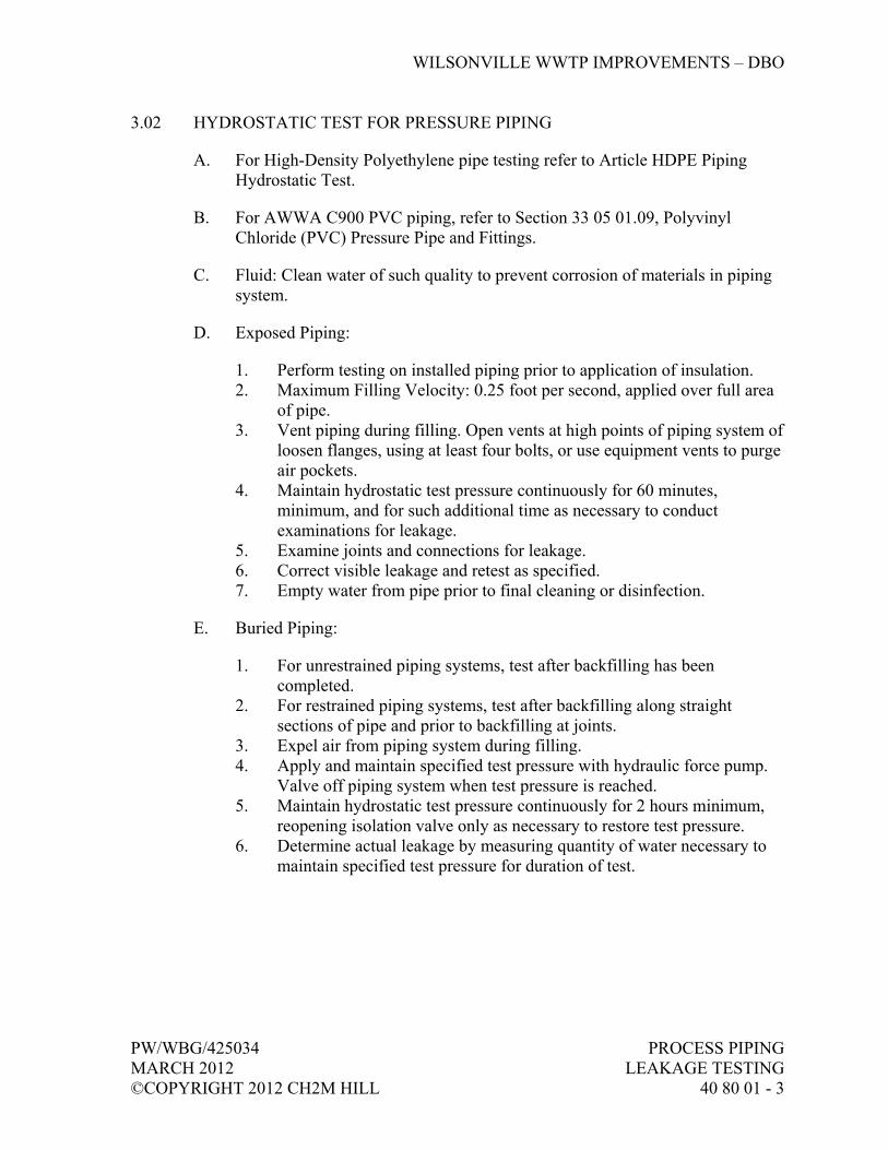
WILSONVILLE WWTP IMPROVEMENTS – DBO
PW/WBG/425034 PROCESS PIPING MARCH 2012 LEAKAGE TESTING ©COPYRIGHT 2012 CH2M HILL 40 80 01 - 3
3.02 HYDROSTATIC TEST FOR PRESSURE PIPING
A. For High-Density Polyethylene pipe testing refer to Article HDPE Piping Hydrostatic Test.
B. For AWWA C900 PVC piping, refer to Section 33 05 01.09, Polyvinyl Chloride (PVC) Pressure Pipe and Fittings.
C. Fluid: Clean water of such quality to prevent corrosion of materials in piping system.
D. Exposed Piping:
1. Perform testing on installed piping prior to application of insulation. 2. Maximum Filling Velocity: 0.25 foot per second, applied over full area
of pipe. 3. Vent piping during filling. Open vents at high points of piping system of
loosen flanges, using at least four bolts, or use equipment vents to purge air pockets.
4. Maintain hydrostatic test pressure continuously for 60 minutes, minimum, and for such additional time as necessary to conduct examinations for leakage.
5. Examine joints and connections for leakage. 6. Correct visible leakage and retest as specified. 7. Empty water from pipe prior to final cleaning or disinfection.
E. Buried Piping:
1. For unrestrained piping systems, test after backfilling has been completed.
2. For restrained piping systems, test after backfilling along straight sections of pipe and prior to backfilling at joints.
3. Expel air from piping system during filling. 4. Apply and maintain specified test pressure with hydraulic force pump.
Valve off piping system when test pressure is reached. 5. Maintain hydrostatic test pressure continuously for 2 hours minimum,
reopening isolation valve only as necessary to restore test pressure. 6. Determine actual leakage by measuring quantity of water necessary to
maintain specified test pressure for duration of test.
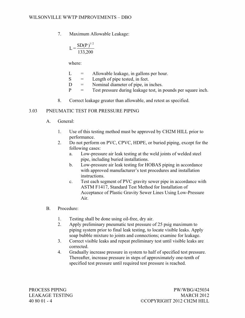
WILSONVILLE WWTP IMPROVEMENTS – DBO
PROCESS PIPING PW/WBG/425034 LEAKAGE TESTING MARCH 2012 40 80 01 - 4 ©COPYRIGHT 2012 CH2M HILL
7. Maximum Allowable Leakage:
200,133)D(PS
= L2/1
where:
L = Allowable leakage, in gallons per hour. S = Length of pipe tested, in feet. D = Nominal diameter of pipe, in inches. P = Test pressure during leakage test, in pounds per square inch.
8. Correct leakage greater than allowable, and retest as specified.
3.03 PNEUMATIC TEST FOR PRESSURE PIPING
A. General:
1. Use of this testing method must be approved by CH2M HILL prior to performance.
2. Do not perform on PVC, CPVC, HDPE, or buried piping, except for the following cases: a. Low-pressure air leak testing at the weld joints of welded steel
pipe, including buried installations. b. Low-pressure air leak testing for HOBAS piping in accordance
with approved manufacturer’s test procedures and installation instructions.
c. Test each segment of PVC gravity sewer pipe in accordance with ASTM F1417, Standard Test Method for Installation of Acceptance of Plastic Gravity Sewer Lines Using Low-Pressure Air.
B. Procedure:
1. Testing shall be done using oil-free, dry air. 2. Apply preliminary pneumatic test pressure of 25 psig maximum to
piping system prior to final leak testing, to locate visible leaks. Apply soap bubble mixture to joints and connections; examine for leakage.
3. Correct visible leaks and repeat preliminary test until visible leaks are corrected.
4. Gradually increase pressure in system to half of specified test pressure. Thereafter, increase pressure in steps of approximately one-tenth of specified test pressure until required test pressure is reached.

WILSONVILLE WWTP IMPROVEMENTS – DBO
PW/WBG/425034 PROCESS PIPING MARCH 2012 LEAKAGE TESTING ©COPYRIGHT 2012 CH2M HILL 40 80 01 - 5
5. Maintain pneumatic test pressure continuously for minimum of 10 minutes and for such additional time as necessary to conduct soap bubble examination for leakage.
6. Correct visible leakage and retest as specified.
C. Allowable Leakage: Piping system, exclusive of possible localized instances at pump or valve packing, shall show no visual evidence of leakage.
D. After testing and final cleaning, purge with nitrogen those lines that will carry flammable gases to assure no explosive mixtures will be present in system during filling process.
3.04 HYDROSTATIC TEST FOR GRAVITY PIPING
A. Testing Equipment Accuracy: Plus or minus 1/2 gallon water leakage under specified conditions.
B. Maximum Allowable Leakage: 0.16 gallon per hour per inch diameter per 100 feet. Include service connection footage in test section, subjected to minimum head specified.
C. Gravity Sanitary and Roof Drain Piping: Test shall be in accordance with current adopted International Plumbing Code. Test with 10 feet of water to include highest horizontal vent in filled piping. Where vertical drain and vent systems exceed 10 feet in height, test systems in 10-foot vertical sections as piping is installed.
D. Exfiltration Test:
1. Hydrostatic Head: a. At least 6 feet above maximum estimated groundwater level in
section being tested. b. No less than 6 feet above inside top of highest section of pipe in
test section, including service connections. 2. Length of Pipe Tested: Limit length such that pressure on invert of
lower end of section does not exceed 30 feet of water column.
E. Infiltration Test:
1. Groundwater Level: At least 6 feet above inside top of highest section of pipe in test section, including service connections.
F. Piping with groundwater infiltration rate greater than allowable leakage rate for exfiltration will be considered defective even if pipe previously passed a pressure test.

WILSONVILLE WWTP IMPROVEMENTS – DBO
PROCESS PIPING PW/WBG/425034 LEAKAGE TESTING MARCH 2012 40 80 01 - 6 ©COPYRIGHT 2012 CH2M HILL
G. Defective Piping Sections: Replace or test and seal individual joints, and retest as specified.
3.05 HDPE PIPING HYDROSTATIC TEST
A. Procedure:
1. Test pressure shall be as indicated in the Piping Schedule. 2. Maximum filling velocity shall not exceed 0.25 foot per second,
calculated based on full area of the pipe. 3. Expel air from pipe system during filling. 4. Test procedure consists of two steps: initial expansion phase and test
phase. During initial expansion phase, apply and maintain specified test pressure with hydraulic force pump. Valve off piping system when test pressure is reached. Add make-up water at hourly intervals for 3 hours to maintain test pressure. Continue initial expansion phase for 4 hours and then begin test phase. Test phase shall continue for 1 hour.
5. At conclusion of test phase, determine actual leakage by measuring quantity of water necessary to return system to test pressure.
6. If test is not completed due to leakage, equipment failure, or other reasons, depressurize test section and allow it to relax for at least 8 hours before retesting.
7. If measured leakage exceeds allowable leakage or if leaks are visible, repair defective pipe section and repeat hydrostatic test.
B. Allowable Leakage:
1. Maximum allowable make-up water at conclusion of test phase shall not exceed recommended amounts stated in the following table.
2. Table is based on test pressure equal to 1.5 times pressure class of pipe. If lower pressure is used for test, allowances shall be reduced by ratio of test pressure to pressure class of pipe.
Make-Up Water Allowance for Test Phase (U.S. Gallons per 100 feet of Pipe)
Nominal Pipe Size(inches)
1-Hour Test(gallons)
2-Hour Test(gallons)
3-Hour Test (gallons)
3 0.10 0.15 0.25 4 0.13 0.25 0.40 6 0.30 0.60 0.90 8 0.50 1.0 1.5 10 0.75 1.3 2.1 12 1.1 2.3 3.4 14 1.4 2.8 4.2

WILSONVILLE WWTP IMPROVEMENTS – DBO
PW/WBG/425034 PROCESS PIPING MARCH 2012 LEAKAGE TESTING ©COPYRIGHT 2012 CH2M HILL 40 80 01 - 7
Make-Up Water Allowance for Test Phase (U.S. Gallons per 100 feet of Pipe)
Nominal Pipe Size(inches)
1-Hour Test(gallons)
2-Hour Test (gallons)
3-Hour Test (gallons)
16 1.7 3.3 5.0 18 2.2 4.3 6.5 20 2.8 5.5 8.0 24 4.5 8.9 13.3 28 5.5 11.1 16.8 32 7.0 14.3 21.5 36 9.0 18.0 27.0 40 11.0 22.0 33.0 42 12.0 22.5 35.0 48 15.0 27.0 43.0 54 18.0 30.0 50.0 63 27.0 54.0 81.0
3.06 FIELD QUALITY CONTROL
A. Test Report Documentation:
1. Test date. 2. Description and identification of piping tested. 3. Test fluid. 4. Test pressure. 5. Remarks, including:
a. Leaks (type, location). b. Repair/replacement performed to remedy excessive leakage.
6. Signed by the Subcontractor and CH2M HILL’s Engineer to validate that test has been satisfactorily completed.
END OF SECTION


WILSONVILLE WWTP IMPROVEMENTS – DBO
PW/WBG/425034 INSTRUMENTATION COMPONENTS MARCH 2012 40 91 00 - 1 ©COPYRIGHT 2012 CH2M HILL
SECTION 40 91 00 INSTRUMENTATION COMPONENTS
PART 1 GENERAL
1.01 WORK OF THIS SECTION
A. This Section gives the requirements for furnishing instrumentation components.
1.02 RELATED SECTIONS
A. Related sections include the following:
1. Division 1, General Requirements.
1.03 SUBMITTALS
A. General: In accordance with Section 01 33 00, Submittal Procedures.
B. Action Submittals:
1. Purchase Quotation: Proposed listing of instruments, components, and accessories to be provided. Include applicable tag numbers and component codes assigned in the Instrument Data Sheets in Article Supplements at the end of this Section.
2. Order Confirmation Summary: Final listing of instruments, components, and accessories to be provided.
3. Data Sheets: a. Neat and legible markups of data sheets provided in this Section. b. Markup the data sheets to include complete product information
and corrections to reflect all items in the purchase quotation.
C. Informational Submittals:
1. Provide Manufacturer’s O&M: In accordance with Section 01 78 23, Operation, Maintenance, and Asset Data. a. Content for Each O&M Manual:
1) Table of Contents. 2) Operations procedures. 3) Installation requirements and procedures. 4) Maintenance requirements and procedures. 5) Troubleshooting procedures. 6) Calibration procedures.

WILSONVILLE WWTP IMPROVEMENTS – DBO
INSTRUMENTATION COMPONENTS PW/WBG/425034 40 91 00 - 2 MARCH 2012 ©COPYRIGHT 2012 CH2M HILL
7) Internal schematic and wiring diagrams. 8) Component factory calibration sheets.
2. List of spares, expendables, test equipment and tools provided. 3. List of additional recommended spares, expendables, test equipment,
and tools. Include quantities, unit prices, and total costs. 4. Provide Manufacturer’s Certificate of Proper Installation.
1.04 DELIVERY, STORAGE, AND HANDLING
A. In accordance with Section 01 61 00, Common Product Requirements.
B. Packaged at the factory prior to shipment to protect each item from damage during shipment and storage. Containers protected against impact, abrasion, corrosion, discoloration and/or other damages. Clearly label contents of each container and provide information on the required storage conditions necessary for the equipment.
C. Notify Engineer of the storage requirements and recommendations for the equipment prior to shipment.
D. Prior to shipment, include corrosive inhibitive vapor capsules in shipping containers, and related equipment as recommended by capsule manufacturer.
PART 2 PRODUCTS
2.01 GENERAL
A. Provide components that are listed in the Instrument List in Article Supplements at the end of this Section. Specific component requirements are defined in the Instrument Data Sheets in Article Supplements at the end of this Section.
PART 3 EXECUTION
3.01 MANUFACTURER’S SERVICES
A. Manufacturer’s Certificate of Proper Installation: Provide for each component listed in the component data sheets.
B. Specialty Equipment: For certain components identified in the Instrument List or Instrument Data Sheets, provide services of qualified manufacturer’s representative during installation, startup, demonstration testing, and training.
WILSONVILLE WWTP IMPROVEMENTS – DBO
PW/WBG/425034 INSTRUMENTATION COMPONENTS MARCH 2012 40 91 00 - 3 ©COPYRIGHT 2012 CH2M HILL
3.02 SUPPLEMENTS
A. The supplements listed below, following “End of Section,” are part of this Specification.
1. Instrument List. 2. Instrument Data Sheets.
END OF SECTION

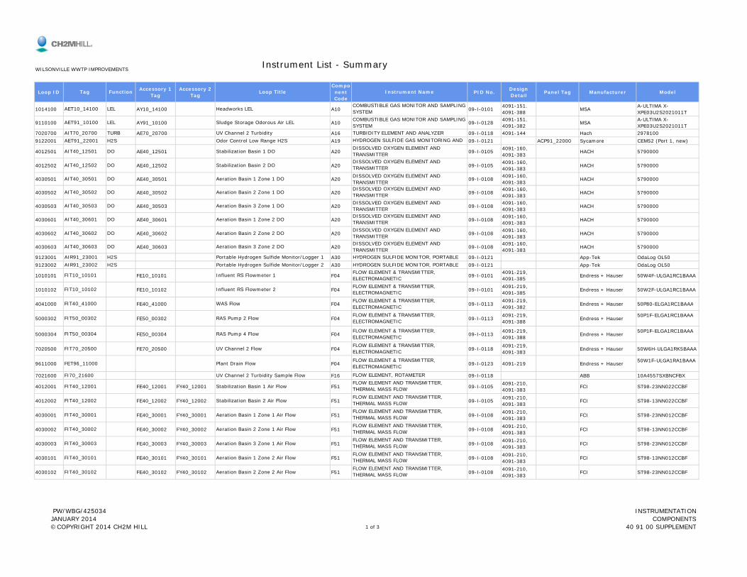
Loop ID Accessory 1 Tag
Accessory 2 Tag
Component Code
PID No. Design Detail Panel Tag Manufacturer Model
1014100 AY10_14100 A10 09-I-0101 4091-151. 4091-388 MSA A-ULTIMA X-
XPE03U2S2021011T
9110100 AY91_10100 A10 09-I-0128 4091-151. 4091-382 MSA A-ULTIMA X-
XPE03U2S2021011T7020700 AE70_20700 A16 09-I-0118 4091-144 Hach 29781009122001 A19 09-I-0121 ACP91_22000 Sycamore CEM52 (Port 1, new)
4012501 AE40_12501 A20 09-I-0105 4091-160, 4091-383 HACH 5790000
4012502 AE40_12502 A20 09-I-0105 4091-160, 4091-383 HACH 5790000
4030501 AE40_30501 A20 09-I-0108 4091-160, 4091-383 HACH 5790000
4030502 AE40_30502 A20 09-I-0108 4091-160, 4091-383 HACH 5790000
4030503 AE40_30503 A20 09-I-0108 4091-160, 4091-383 HACH 5790000
4030601 AE40_30601 A20 09-I-0108 4091-160, 4091-383 HACH 5790000
4030602 AE40_30602 A20 09-I-0108 4091-160, 4091-383 HACH 5790000
4030603 AE40_30603 A20 09-I-0108 4091-160, 4091-383 HACH 5790000
9123001 A30 09-I-0121 App-Tek OdaLog OL509123002 A30 09-I-0121 App-Tek OdaLog OL50
1010101 FE10_10101 F04 09-I-0101 4091-219, 4091-385 Endress + Hauser 50W4F-ULGA1RC1BAAA
1010102 FE10_10102 F04 09-I-0101 4091-219, 4091-385 Endress + Hauser 50W2F-ULGA1RC1BAAA
4041000 FE40 41000 F04 09-I-0113 4091-219, Endress + Hauser 50P80-ELGA1RC1BAAAFIT40 41000 WAS Flow FLOW ELEMENT & TRANSMITTER,
FIT10_10101 Influent RS Flowmeter 1 FLOW ELEMENT & TRANSMITTER, ELECTROMAGNETIC
FIT10_10102 Influent RS Flowmeter 2 FLOW ELEMENT & TRANSMITTER, ELECTROMAGNETIC
AIR91_23001 H2S Portable Hydrogen Sulfide Monitor/Logger 1 HYDROGEN SULFIDE MONITOR, PORTABLEAIR91_23002 H2S Portable Hydrogen Sulfide Monitor/Logger 2 HYDROGEN SULFIDE MONITOR, PORTABLE
AIT40_30602 DO Aeration Basin 2 Zone 2 DO DISSOLVED OXYGEN ELEMENT AND TRANSMITTER
AIT40_30603 DO Aeration Basin 3 Zone 2 DO DISSOLVED OXYGEN ELEMENT AND TRANSMITTER
AIT40_30503 DO Aeration Basin 3 Zone 1 DO DISSOLVED OXYGEN ELEMENT AND TRANSMITTER
AIT40_30601 DO Aeration Basin 1 Zone 2 DODISSOLVED OXYGEN ELEMENT AND TRANSMITTER
AIT40_30501 DO Aeration Basin 1 Zone 1 DO DISSOLVED OXYGEN ELEMENT AND TRANSMITTER
AIT40_30502 DO Aeration Basin 2 Zone 1 DODISSOLVED OXYGEN ELEMENT AND TRANSMITTER
AIT40_12501 DO Stabilization Basin 1 DO DISSOLVED OXYGEN ELEMENT AND TRANSMITTER
AIT40_12502 DO Stabilization Basin 2 DODISSOLVED OXYGEN ELEMENT AND TRANSMITTER
AIT70_20700 TURB UV Channel 2 Turbidity TURBIDITY ELEMENT AND ANALYZERAET91_22001 H2S Odor Control Low Range H2S HYDROGEN SULFIDE GAS MONITORING AND
AET10_14100 LEL Headworks LELCOMBUSTIBLE GAS MONITOR AND SAMPLING SYSTEM
AET91_10100 LEL Sludge Storage Odorous Air LEL COMBUSTIBLE GAS MONITOR AND SAMPLING SYSTEM
Instrument List - Summary
Tag Function Loop Title Instrument Name
WILSONVILLE WWTP IMPROVEMENTS
4041000 FE40_41000 F04 09-I-0113 4091-382 Endress + Hauser 50P80-ELGA1RC1BAAA
5000302 FE50_00302 F04 09-I-0113 4091-219, 4091-388 Endress + Hauser 50P1F-ELGA1RC1BAAA
5000304 FE50_00304 F04 09-I-0113 4091-219, 4091-388 Endress + Hauser 50P1F-ELGA1RC1BAAA
7020500 FE70_20500 F04 09-I-0118 4091-219, 4091-383 Endress + Hauser 50W6H-ULGA1RK5BAAA
9611000 F04 09-I-0123 4091-219 Endress + Hauser 50W1F-ULGA1RA1BAAA
7021600 F16 09-I-0118 ABB 10A4557SXBNCFBX
4012001 FE40_12001 FY40_12001 F51 09-I-0105 4091-210, 4091-383 FCI ST98-23NN022CCBF
4012002 FE40_12002 FY40_12002 F51 09-I-0105 4091-210, 4091-383 FCI ST98-13NN022CCBF
4030001 FE40_30001 FY40_30001 F51 09-I-0108 4091-210, 4091-383 FCI ST98-23NN012CCBF
4030002 FE40_30002 FY40_30002 F51 09-I-0108 4091-210, 4091-383 FCI ST98-13NN012CCBF
4030003 FE40_30003 FY40_30003 F51 09-I-0108 4091-210, 4091-383 FCI ST98-23NN012CCBF
4030101 FE40_30101 FY40_30101 F51 09-I-0108 4091-210, 4091-383 FCI ST98-13NN012CCBF
4030102 FE40_30102 FY40_30102 F51 09-I-0108 4091-210, 4091-383 FCI ST98-23NN012CCBFFIT40_30102 Aeration Basin 2 Zone 2 Air Flow
FLOW ELEMENT AND TRANSMITTER, THERMAL MASS FLOW
FIT40_30003 Aeration Basin 3 Zone 1 Air FlowFLOW ELEMENT AND TRANSMITTER, THERMAL MASS FLOW
FIT40_30101 Aeration Basin 1 Zone 2 Air FlowFLOW ELEMENT AND TRANSMITTER, THERMAL MASS FLOW
FIT40_30001 Aeration Basin 1 Zone 1 Air FlowFLOW ELEMENT AND TRANSMITTER, THERMAL MASS FLOW
FIT40_30002 Aeration Basin 2 Zone 1 Air FlowFLOW ELEMENT AND TRANSMITTER, THERMAL MASS FLOW
FIT40_12001 Stabilization Basin 1 Air FlowFLOW ELEMENT AND TRANSMITTER, THERMAL MASS FLOW
FIT40_12002 Stabilization Basin 2 Air FlowFLOW ELEMENT AND TRANSMITTER, THERMAL MASS FLOW
FET96_11000 Plant Drain Flow FLOW ELEMENT & TRANSMITTER, ELECTROMAGNETIC
FI70_21600 UV Channel 2 Turbidity Sample Flow FLOW ELEMENT, ROTAMETER
FIT50_00304 RAS Pump 4 Flow FLOW ELEMENT & TRANSMITTER, ELECTROMAGNETIC
FIT70_20500 UV Channel 2 Flow FLOW ELEMENT & TRANSMITTER, ELECTROMAGNETIC
FIT40_41000 WAS FlowELECTROMAGNETIC
FIT50_00302 RAS Pump 2 Flow FLOW ELEMENT & TRANSMITTER, ELECTROMAGNETIC
PW/WBG/425034 JANUARY 2014 ©COPYRIGHT 2014 CH2M HILL 1 of 3
INSTRUMENTATION COMPONENTS
40 91 00 SUPPLEMENT

Loop ID Accessory 1 Tag
Accessory 2 Tag
Component Code
PID No. Design Detail Panel Tag Manufacturer Model
Instrument List - Summary
Tag Function Loop Title Instrument Name
WILSONVILLE WWTP IMPROVEMENTS
4030103 FE40_30103 FY40_30103 F51 09-I-0108 4091-210, 4091-383 FCI ST98-13NN012CCBF
1010600 L08 09-I-0101 4091-275G Anchor Scientific P30NO1010600 L08 09-I-0101 4091-275G Anchor Scientific P30NO1012100 L08 09-I-0101 4091-275G Anchor Scientific P30NO5311000 L08 09-I-0115 4091-275G Anchor Scientific P30NO5311000 L08 09-I-0115 4091-275G Anchor Scientific P30NO5511201 L08 09-I-0116 4091-275G Anchor Scientific P30NO5511202 L08 09-I-0116 4091-275G Anchor Scientific P30NO7840200 L08 09-I-0132 4091-275G Anchor Scientific P30NO7840200 L08 09-I-0132 4091-275G Anchor Scientific P30NO8210201 L08 09-I-0125 4091-275G Anchor Scientific P30NO8210202 L08 09-I-0125 4091-275G Anchor Scientific P30NO8220201 L08 09-I-0128 4091-275G Anchor Scientific P30NO8220202 L08 09-I-0128 4091-275G Anchor Scientific P30NO1012100 L29 09-I-0101 4091-258 Endress + Hauser FMR230-S4VAVJAA4A1012200 L29 09-I-0101 4091-258 Endress + Hauser FMR230-S4VAVJAA4A5311000 L29 09-I-0115 4091-259 Endress + Hauser FMR230-A4VAVJAA4A
4012701 L41 09-I-0105 4091-264 Endress + Hauser FMX21-FE221GGE21APRPSZ1
4012702 L41 09-I-0105 4091-264 Endress + Hauser FMX21-FE221GGE21APRPSZ1
5020200 L41 09-I-0114 4091-261 Endress + Hauser FMX21-FE221GGE21APRPSZ1
7010500 L41 09-I-0118 4091-263 Endress + Hauser FMX21-AA211DGE21APRPSZ1
1013400 L50 09-I-0101 4091-266 Endress + Hauser FTL51-RAE2CB4E5ALSH10_13400 Screenings Sluice Trough Level LEVEL SWITCH, TUNING FORKHS80 00201 OOR B l W h W P 1 SELECTOR SWITCH
LET50_20200 Secondary Scum Pit Level LEVEL TRANSMITTER, SUBMERSIBLE
LET70_10500 UV Channel 1 Level LEVEL TRANSMITTER, SUBMERSIBLE
LET40_12701 Stabilization Basin 1 Level LEVEL TRANSMITTER, SUBMERSIBLE
LET40_12702 Stabilization Basin 2 Level LEVEL TRANSMITTER, SUBMERSIBLE
LET10_12200 Headworks Effluent Channel Level LEVEL ELEMENT AND TRANSMITTER, RADARLET53_11000 Secondary Effluent Wetwell Level LEVEL ELEMENT AND TRANSMITTER, RADAR
LSL82_20202 TWAS Storage Tank 2 Level LEVEL SWITCH, FLOATLET10_12100 Headworks Influent Channel Level LEVEL ELEMENT AND TRANSMITTER, RADAR
LSL82_10202 WAS Storage Tank 2 Level LEVEL SWITCH, FLOATLSL82_20201 TWAS Storage Tank 1 Level LEVEL SWITCH, FLOAT
LSL78_40200 Dryer Condensate Sump Pump Level LEVEL SWITCH, FLOATLSL82_10201 WAS Storage Tank 1 Level LEVEL SWITCH, FLOAT
LSH55_11202 SE Cooling Tower 2 Level LEVEL SWITCH, FLOATLSH78_40200 Dryer Condensate Sump Pump Level LEVEL SWITCH, FLOAT
LSL53_11000 Secondary Effluent Wetwell Level LEVEL SWITCH, FLOATLSH55_11201 SE Cooling Tower 1 Level LEVEL SWITCH, FLOAT
LSH10_12100 Headworks Influent Channel Level LEVEL SWITCH, FLOATLSH53_11000 Secondary Effluent Wetwell Level LEVEL SWITCH, FLOAT
LSH10_10600 Vactor Sump Pump LEVEL SWITCH, FLOATLSL10_10600 Vactor Sump Pump LEVEL SWITCH, FLOAT
FIT40_30103 Aeration Basin 3 Zone 2 Air FlowFLOW ELEMENT AND TRANSMITTER, THERMAL MASS FLOW
8000201 M22 09-I-0126 LCP80_04A LCP80_04A8000202 M22 09-I-0126 LCP80_04A LCP80_04A8210001 M22 09-I-0125 LCP80_04A LCP80_04A8210002 M22 09-I-0125 LCP80_04A LCP80_04A8000201 M31 09-I-0126 LCP80_04A LCP80_04A8000202 M31 09-I-0126 LCP80_04A LCP80_04A8210001 M31 09-I-0125 LCP80_04A LCP80_04A8210002 M31 09-I-0125 LCP80_04A LCP80_04A
9110601 P03 09-I-0120 4091-307, 4091-380 Endress + Hauser PMD70-SBC7D42BAU
9110602 P03 09-I-0120 4091-307, 4091-380 Endress + Hauser PMD70-SBC7D42BAU
1010700 PE10_10700 P04 09-I-0101 4091-304 Ashcroft 45 1259SD 04L 15#
1030600 PE10_30600 P04 09-I-0104 4091-304 Ashcroft 45 1259SL 04L XC4 15PSI
1030700 PE10_30700 P04 09-I-0104 4091-304 Ashcroft 45 1259SD 04L 60#5003101 PE50_03101 P04 09-I-0113 4091-303 Ashcroft 45 1259SD 04L 15#5003102 PE50_03102 P04 09-I-0113 4091-303 Ashcroft 45 1259SD 04L 15#5003103 PE50_03103 P04 09-I-0113 4091-303 Ashcroft 45 1259SD 04L 15#5003104 PE50_03104 P04 09-I-0113 4091-303 Ashcroft 45 1259SD 04L 15#5003201 PE50_03201 P04 09-I-0113 4091-303 Ashcroft 45 1259SD 04L 15#5003202 PE50_03202 P04 09-I-0113 4091-303 Ashcroft 45 1259SD 04L 15#5003203 PE50_03203 P04 09-I-0113 4091-303 Ashcroft 45 1259SD 04L 15#5003204 PE50_03204 P04 09-I-0113 4091-303 Ashcroft 45 1259SD 04L 15#
PI50_03203 RAS Pump 3 Discharge Pressure PRESSURE GAUGEPI50_03204 RAS Pump 4 Discharge Pressure PRESSURE GAUGE
PI50_03201 RAS Pump 1 Discharge Pressure PRESSURE GAUGEPI50_03202 RAS Pump 2 Discharge Pressure PRESSURE GAUGE
PI50_03103 RAS Pump 3 Suction Pressure PRESSURE GAUGEPI50_03104 RAS Pump 4 Suction Pressure PRESSURE GAUGE
PI50_03101 RAS Pump 1 Suction Pressure PRESSURE GAUGEPI50_03102 RAS Pump 2 Suction Pressure PRESSURE GAUGE
PI10_30600 Grit Pump Suction Pressure PRESSURE GAUGE
PI10_30700 Grit Pump Discharge Pressure PRESSURE GAUGE
PDT91_10602 Odor Control Fan 2 Differential Pressure PRESSURE DIFFERENTIAL TRANSMITTER, ELECTRONIC
PI10_10700 Vactor Sump Pump Discharge Pressure PRESSURE GAUGE
YL82_10002 ON GBT Feed Pump 2 INDICATING LIGHT
PDT91_10601 Odor Control Fan 1 Differential Pressure PRESSURE DIFFERENTIAL TRANSMITTER, ELECTRONIC
YL80_00202 ON Belt Wash Water Pump 2 INDICATING LIGHTYL82_10001 ON GBT Feed Pump 1 INDICATING LIGHT
HS82_10002 OOR GBT Feed Pump 2 SELECTOR SWITCHYL80_00201 ON Belt Wash Water Pump 1 INDICATING LIGHT
HS80_00202 OOR Belt Wash Water Pump 2 SELECTOR SWITCHHS82_10001 OOR GBT Feed Pump 1 SELECTOR SWITCH
HS80_00201 OOR Belt Wash Water Pump 1 SELECTOR SWITCH
PW/WBG/425034 JANUARY 2014 ©COPYRIGHT 2014 CH2M HILL 2 of 3
INSTRUMENTATION COMPONENTS
40 91 00 SUPPLEMENT
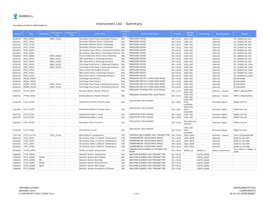
Loop ID Accessory 1 Tag
Accessory 2 Tag
Component Code
PID No. Design Detail Panel Tag Manufacturer Model
Instrument List - Summary
Tag Function Loop Title Instrument Name
WILSONVILLE WWTP IMPROVEMENTS
5020300 PE50_20300 P04 09-I-0114 4091-303 Ashcroft 45 1259SD 04L 60#5310101 P04 09-I-0115 4091-302 Ashcroft 45 1259SD 04L 60#5310102 P04 09-I-0115 4091-302 Ashcroft 45 1259SD 04L 60#5310103 P04 09-I-0115 4091-302 Ashcroft 45 1259SD 04L 60#5510601 P04 09-I-0116 4091-302 Ashcroft 45 1259SD 04L 30#5510602 P04 09-I-0116 4091-302 Ashcroft 45 1259SD 04L 30#7840300 PE78_40300 P04 09-I-0132 4091-303 Ashcroft 45 1259SD 04L 30#8210101 PE82_10101 P04 09-I-0125 4091-304 Ashcroft 45 1259SD 04L 30#8210102 PE82_10102 P04 09-I-0125 4091-304 Ashcroft 45 1259SD 04L 30#8220101 PE82_20101 P04 09-I-0128 4091-304 Ashcroft 45 1259SD 04L 100#8220102 PE82_20102 P04 09-I-0128 4091-304 Ashcroft 45 1259SD 04L 100#9112601 P04 09-I-0120 4091-302 Ashcroft 45 1259SD 04L 160#9610101 P04 09-I-0123 4091-302 Ashcroft 45 1259SD 04L 160#9610102 P04 09-I-0123 4091-302 Ashcroft 45 1259SD 04L 160#8220001 P08 09-I-0128 4091-302 Ashcroft B724B 60PSI8220002 P08 09-I-0128 4091-302 Ashcroft B724B 60PSI8220101 PE82_20101 P08 09-I-0128 4091-304 Ashcroft B724B 60PSI8220102 PE82_20102 P08 09-I-0128 4091-304 Ashcroft B724B 60PSI
4050501 P09 09-I-0110 4091-308, 4091-381 Endress + Hauser PMP71-AB31K61RHA
4050502 P09 09-I-0110 4091-308, 4091-381 Endress + Hauser PMP71-AB31K61RHA
1012100 S12 09-I-01014091-385; Omit sunshield
Precision Digital PD662-0L0-00
1012200 S12 09-I-01014091-385; Omit sunshield
Precision Digital PD662-0L0-00
LI10_12100 Headworks Influent Channel Level INDICATOR, FIELD MOUNT
LI10_12200 Headworks Effluent Channel Level INDICATOR, FIELD MOUNT
PIT40_50501 Aeration Blower Header Pressure PRESSURE TRANSMITTER, ELECTRONIC
PIT40_50502 Existing Blowers Header Pressure PRESSURE TRANSMITTER, ELECTRONIC
PSH82_20101 Centrifuge Feed Pump 1 Discharge Pressure PRESSURE SWITCH, FIXED DEAD BANDPSH82_20102 Centrifuge Feed Pump 2 Discharge Pressure PRESSURE SWITCH, FIXED DEAD BAND
PSL82_20001 Centrifuge Feed Pump 1 PRESSURE SWITCH, FIXED DEAD BANDPSL82_20002 Centrifuge Feed Pump 2 PRESSURE SWITCH, FIXED DEAD BAND
PI96_10101 Plant Drain Pump 1 Discharge Pressure PRESSURE GAUGEPI96_10102 Plant Drain Pump 2 Discharge Pressure PRESSURE GAUGE
PI82_20102 Centrifuge Feed Pump 2 Discharge Pressure PRESSURE GAUGEPI91_12601 Odor Control W3 Supply Pressure PRESSURE GAUGE
PI82_10102 GBT Feed Pump 2 Discharge Pressure PRESSURE GAUGEPI82_20101 Centrifuge Feed Pump 1 Discharge Pressure PRESSURE GAUGE
PI78_40300 Dryer Condensate Sump Pump Discharge PRESSURE GAUGEPI82_10101 GBT Feed Pump 1 Discharge Pressure PRESSURE GAUGE
PI55_10601 SE Cooling Tower Pump 1 Discharge Pressure PRESSURE GAUGEPI55_10602 SE Cooling Tower Pump 2 Discharge Pressure PRESSURE GAUGE
PI53_10102 Secondary Effluent Pump 2 Discharge PRESSURE GAUGEPI53_10103 Secondary Effluent Pump 3 Discharge PRESSURE GAUGE
PI50_20300 Secondary Scum Pump Discharge Pressure PRESSURE GAUGEPI53_10101 Secondary Effluent Pump 1 Discharge PRESSURE GAUGE
sunshield4012701 S12 09-I-0105 4091-383 Precision Digital PD662-0L0-004012702 S12 09-I-0105 4091-383 Precision Digital PD662-0L0-00
5020200 S12 09-I-0114 See Electrical drawing Precision Digital PD663-0L0-00
7010500 S12 09-I-01184091-382; Omit sunshield
Precision Digital PD662-0L0-00
7021700 TE70_21700 T03 09-I-0118 4091-361B Endress + Hauser TH13-1A32A2AIM1BK5510101 T09 09-I-0116 4091-361B Ashcroft 600B-01-AG-XNN5510102 T09 09-I-0116 4091-361B Ashcroft 600B-01-AG-XNN5510201 T09 09-I-0116 4091-361B Ashcroft 600B-01-AG-XNN5510202 T09 09-I-0116 4091-361B Ashcroft 600B-01-AG-XNN
9510000 T21 09-I-0133 NIP95_01 NIP95_01 Moore Instruments T2X / PT10 / 4-20MA / 8-42DC
7850001 X02 09-I-0133 LCP78_500007850002 X02 09-I-0133 LCP78_500007850003 X02 09-I-0133 LCP78_500007850004 X02 09-I-0133 LCP78_500007850005 X02 09-I-0133 LCP78_500007850006 X02 09-I-0133 LCP78_50000
QT78_50005 RAIN Weather Station Rain Gauge WEATHER ELEMENT AND TRANSMITTERPT78_50006 Weather Station Atmospheric Pressure WEATHER ELEMENT AND TRANSMITTER
AT78_50003 RH Weather Station Humidity WEATHER ELEMENT AND TRANSMITTERZT78_50004 WIND Weather Station Wind Direction WEATHER ELEMENT AND TRANSMITTER
TT78_50001 Weather Station Temperature WEATHER ELEMENT AND TRANSMITTERST78_50002 WIND Weather Station Wind Speed WEATHER ELEMENT AND TRANSMITTER
TI55_10202 SE Cooling Tower 2 Effluent Temperature THERMOMETER, ADJUSTABLE ANGLE
TIT95_10000 NIP95_01 Room Temperature TEMPERATURE ELEMENT & TRANSMITTER, ROOM
TI55_10102 SE Cooling Tower 2 Influent Temperature THERMOMETER, ADJUSTABLE ANGLETI55_10201 SE Cooling Tower 1 Effluent Temperature THERMOMETER, ADJUSTABLE ANGLE
TIT70_21700 Plant Effluent Temperature TEMPERATURE ELEMENT AND TRANSMITTER, TI55_10101 SE Cooling Tower 1 Influent Temperature THERMOMETER, ADJUSTABLE ANGLE
LI50_20200 Secondary Scum Pit Level INDICATOR, FIELD MOUNT
LI70_10500 UV Channel 1 Level INDICATOR, FIELD MOUNT
LI40_12701 Stabilization Basin 1 Level INDICATOR, FIELD MOUNTLI40_12702 Stabilization Basin 2 Level INDICATOR, FIELD MOUNT
PW/WBG/425034 JANUARY 2014 ©COPYRIGHT 2014 CH2M HILL 3 of 3
INSTRUMENTATION COMPONENTS
40 91 00 SUPPLEMENT


Wilsonville WWTP Improvements
INSTRUMENT DATA SHEETS
PW/WBG/425034 JANUARY 2014 ©COPYRIGHT 2014 CH2M HILL
INSTRUMENT COMPONENTS40 91 00 SUPPLEMENT

A10COMBUSTIBLE GAS MONITOR AND
SAMPLING SYSTEM
PW/WBG/425034 JANUARY 2014 ©COPYRIGHT 2014 CH2M HILL
INSTRUMENT COMPONENTS40 91 00 SUPPLEMENT

1 Tag Number P&ID AET10_14100 09-I-0101_425034234 Line Number Equipment Number5 Line Size Line Schedule6789
1011121314151617181920 Power Supply Voltage 2-Wire 24VDC internal2122232425262728 Set Point 1 Set Point 2 10 Percent FAULT29 Rising303132333435363738394041 Accuracy Repeatability 1.0 Percent LEL424344454647484950515253
Display
24VDC internal PS, low sample flow switch
Deadband
Calibrated Range
AY10_14100
Element MaterialElement Mounting
Affix stainless steel tag with Tag Number
Switch Type
OPTIONS
TaggingCalibration Kit
Sampler Model
Set Point Direction
5 AmpsContact Rating
Failure State
Relay Output - (2)
Backlit LCD
NEMA 7
40 to 175 degF
Mounting Remote
4 to 20 madc
Enclosure Rating
PURCHASE
Loop TitleArea Classification
Element Tag Number
CALIBRATION
Headworks LELClass 1 Div. 2
Ambient Humidity
Element Cable Length
Element Type
ManufacturerModel Number
Sampler Tag
Contact Arrangement SPDT
Vendor Calibration0 - 100 Percent LELFactory calibrate - Provide calibration certificate
MSAA-ULTIMA X-XPE03U2S2021011T
Yes
AET10_14100
WILSONVILLE WWTP IMPROVEMENTSA10
COMBUSTIBLE GAS ANALYZER & TRANSMITTER
Purchase Note
GENERAL
ELEMENT
TRANSMITTER
0 to 100 Percent
Duct
Infrared
Ambient Temperature Limits
SWITCH
Input Power 120VAC
HARTCommunication ProtocolOutput Signal
Voltage 120 VAC

1 Tag Number P&ID AET91_10100 09-I-0128_425034234 Line Number Equipment Number5 Line Size Line Schedule6789
1011121314151617181920 Power Supply Voltage 2-Wire 24VDC internal2122232425262728 Set Point 1 Set Point 2 10 Percent FAULT29 Rising303132333435363738394041 Accuracy Repeatability 1.0 Percent LEL424344454647484950515253
24VDC internal PS, low sample flow switch
Set Point Direction
Calibrated Range
Affix stainless steel tag with Tag Number
Deadband
Switch Type
OPTIONS
TaggingCalibration Kit
Sampler Model
Contact Rating
Failure State
AY91_10100
5 Amps
Element MaterialElement Mounting
Relay Output - (2)
Backlit LCD
NEMA 7
40 to 175 degF
Mounting
PURCHASE
Loop TitleArea Classification
Element Tag Number
CALIBRATION
Sludge Storage Odorous Air LELClass 1 Div. 2
Ambient Humidity
Element Cable Length
Element Type
ManufacturerModel Number
Sampler Tag
Contact Arrangement SPDT
Vendor Calibration0 - 100 Percent LELFactory calibrate - Provide calibration certificate
MSAA-ULTIMA X-XPE03U2S2021011T
Yes
Remote
AET91_10100
WILSONVILLE WWTP IMPROVEMENTSA10
COMBUSTIBLE GAS ANALYZER & TRANSMITTER
Purchase Note
SWITCH
GENERAL
ELEMENT
TRANSMITTER
0 to 100 Percent
Duct
Infrared
Ambient Temperature Limits
4 to 20 madc
Enclosure Rating
Input Power 120VAC
HARTCommunication ProtocolOutput Signal
Voltage 120 VAC
Display

A16TURBIDITY ANALYZER AND
TRANSMITTER
PW/WBG/425034 JANUARY 2014 ©COPYRIGHT 2014 CH2M HILL
INSTRUMENT COMPONENTS40 91 00 SUPPLEMENT
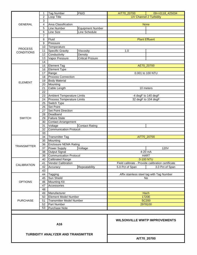
1 Tag Number P&ID AIT70_20700 09-I-0118_4250342345 Line Number Equipment Number6 Line Size Line Schedule789
1011 Specific Gravity Viscosity 1.012 Conductivity Density13 Vapor Pressure Critical Prssure141516171819202122232425262728293031 Voltage Contact Rating323334353637 Power Supply Voltage 120V3839404142 Accuracy Repeatability 5.0 Pct of Span 3.0 Pct of Span4344454647484950515253
Communication Protocol
Field calibrate - Provide calibration certificate
Mounting Kit
4-20 mAHART
AIT70_20700Transmitter Tag
Enclosure NEMA Rating
Accessories
Communication Protocol0-100 NTU
Output Signal
Mounting
Calibrated Range
AE70_20700
Cable Length 10 meters
Range 0.001 to 100 NTU
SWITCH
Hach
AIT70_20700
WILSONVILLE WWTP IMPROVEMENTSA16
TURBIDITY ANALYZER AND TRANSMITTER
1720ESC200
Affix stainless steel tag with Tag NumberNo
ManufacturerElement Model Number
PURCHASE
Loop Title
Area Classification
Fluid
Part NumberPurchase Note
Transmitter Model Number
Switch Type
2978100
OPTIONS
TaggingSun Shield
UV Channel 2 Turbidity
None
Plant Effluent
CALIBRATION
Process Temperature Limits
Element Type
Process Connection
Vendor Calibration
-4 degF to 140 degF32 degF to 104 degF
TRANSMITTER
Set PointSet Point DirectionDeadbandFailure StateContact Arrangement
ELEMENT
PressureTemperature
Body Material
Ambient Temperature Limits
Element Tag
GENERAL
PROCESS CONDITIONS
Mounting

A19HYDROGEN SULFIDE GAS
ANALYZER AND TRANSMITTER
PW/WBG/425034 JANUARY 2014 ©COPYRIGHT 2014 CH2M HILL
INSTRUMENT COMPONENTS40 91 00 SUPPLEMENT

1 Tag Number P&ID AET91_22001 09-I-0121_4250342345 Line Number Equipment Number6 Line Size Line Schedule789
1011 Specific Gravity Viscosity12 Conductivity Density13 Vapor Pressure Critical Prssure141516171819202122232425 Transmitter 1 Tag Transmitter 2 Tag AET91_22001 AET91_2200226272829 Power Supply Voltage 4 - Wire 120 VAC303132333435363738 Accuracy Response Time 5.0 Percent 30 Seconds3940414243444546474849 Model Number1 Model Number 2 CEM52 (Port 1, new) CEM51 (Port 2, existing)50515253
Enclosure NEMA Rating Existing
Vendor Calibration
Communication ProtocolOutput Signal
System Enclosure Tag
Purchase Notes:
Manufacturer
Calibrated Range - Port 1
Sycamore
ACP99_22000
4 to 20 madc
Affix stainless steel tag with Tag Number
0-20 ppm (existing)
AET91_22001
WILSONVILLE WWTP IMPROVEMENTSA19
HYDROGEN SULFIDE GAS ANALYZER AND TRANSMITTER
for existing equipment.
Sensor Type
PURCHASE
Process ConnectionSample Units
OPTIONS
Calibrated Range - Port 2
CALIBRATIONCalibrated Range - Port 3
Tagging
Field calibrate - Provide calibration certificate
0-2 ppm
unit inspection, calibration, & filter replacementProvide Mftr's Representative Services incl.
None
Foul Air
Area Classification
Fluid
-10 degreesF to 105 degreesF
GENERAL
PROCESS CONDITIONS
Loop Title
SENSOR
Sample Ports
Odor Control Low Range H2S
TRANSMITTER
MountingEnclosure Size
Sensor Tag
PressureTemperature
Ambient Temperature Limits
Two (Existing)Sample Flow Rate
1 new, 1 existing
Existing
0.15 to 0.3 Liters/Minute
Existing

A20OXYGEN ANALYZER AND
TRANSMITTER - LDO
PW/WBG/425034 JANUARY 2014 ©COPYRIGHT 2014 CH2M HILL
INSTRUMENT COMPONENTS40 91 00 SUPPLEMENT
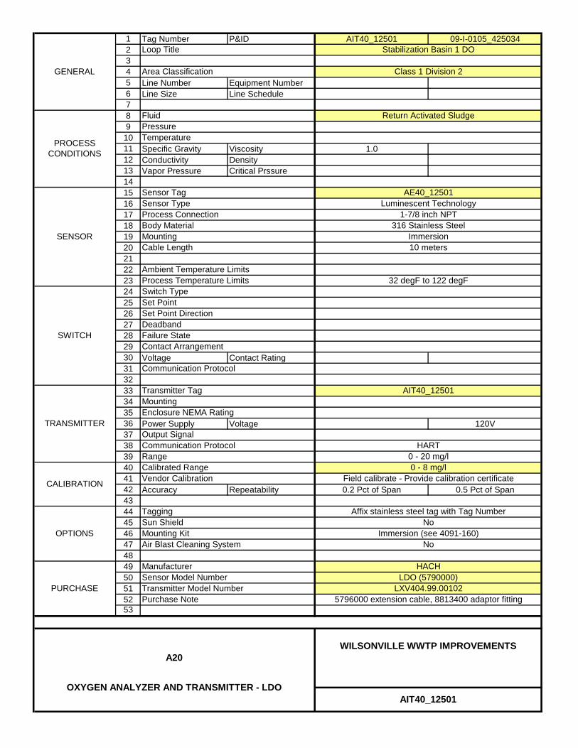
1 Tag Number P&ID AIT40_12501 09-I-0105_4250342345 Line Number Equipment Number6 Line Size Line Schedule789
1011 Specific Gravity Viscosity 1.012 Conductivity Density13 Vapor Pressure Critical Prssure1415161718192021222324252627282930 Voltage Contact Rating313233343536 Power Supply Voltage 120V373839404142 Accuracy Repeatability 0.2 Pct of Span 0.5 Pct of Span4344454647484950515253
Immersion
Stabilization Basin 1 DO
Luminescent Technology1-7/8 inch NPT
AE40_12501
32 degF to 122 degF
10 meters
GENERAL
PROCESS CONDITIONS
Mounting316 Stainless Steel
Deadband
Cable Length
Body Material
Communication Protocol
Sensor TagSensor TypeProcess Connection
Transmitter Tag
Communication Protocol
Failure State
TRANSMITTER
SENSOR
CALIBRATION
Calibrated Range
SWITCH
Switch TypeSet Point
Output Signal
PURCHASE
Loop Title
Area Classification
FluidPressureTemperature
Contact Arrangement
Vendor Calibration
Set Point Direction
Tagging
Process Temperature LimitsAmbient Temperature Limits
OPTIONSNo
ManufacturerSensor Model Number
HACH
Class 1 Division 2
Return Activated Sludge
Mounting
0 - 8 mg/lField calibrate - Provide calibration certificate
LDO (5790000)
Mounting Kit Immersion (see 4091-160)Air Blast Cleaning System No
Sun Shield
AIT40_12501
WILSONVILLE WWTP IMPROVEMENTSA20
OXYGEN ANALYZER AND TRANSMITTER - LDO
Enclosure NEMA Rating
LXV404.99.00102Transmitter Model Number5796000 extension cable, 8813400 adaptor fitting
Range
Affix stainless steel tag with Tag Number
AIT40_12501
Purchase Note
0 - 20 mg/lHART

1 Tag Number P&ID AIT40_12502 09-I-0105_4250342345 Line Number Equipment Number6 Line Size Line Schedule789
1011 Specific Gravity Viscosity 1.012 Conductivity Density13 Vapor Pressure Critical Prssure1415161718192021222324252627282930 Voltage Contact Rating313233343536 Power Supply Voltage 120V373839404142 Accuracy Repeatability 0.2 Pct of Span 0.5 Pct of Span4344454647484950515253
Immersion
Stabilization Basin 2 DO
Luminescent Technology1-7/8 inch NPT
AE40_12502
32 degF to 122 degF
10 meters
GENERAL
PROCESS CONDITIONS
Mounting316 Stainless Steel
Deadband
Cable Length
Body Material
Communication Protocol
Sensor TagSensor TypeProcess Connection
Transmitter Tag
Communication Protocol
Failure State
TRANSMITTER
SENSOR
CALIBRATION
Calibrated Range
SWITCH
Switch TypeSet Point
Output Signal
PURCHASE
Loop Title
Area Classification
FluidPressureTemperature
Contact Arrangement
Vendor Calibration
Set Point Direction
Tagging
Process Temperature LimitsAmbient Temperature Limits
OPTIONSNo
ManufacturerSensor Model Number
HACH
Class 1 Division 2
Return Activated Sludge
Mounting
0 - 8 mg/lField calibrate - Provide calibration certificate
LDO (5790000)
Mounting Kit Immersion (see 4091-160)Air Blast Cleaning System No
Sun Shield
AIT40_12502
WILSONVILLE WWTP IMPROVEMENTSA20
OXYGEN ANALYZER AND TRANSMITTER - LDO
Enclosure NEMA Rating
LXV404.99.00102Transmitter Model Number8813400 adaptor fitting
Range
Affix stainless steel tag with Tag Number
AIT40_12502
Purchase Note
0 - 20 mg/lHART

1 Tag Number P&ID AIT40_30501 09-I-0108_4250342345 Line Number Equipment Number6 Line Size Line Schedule789
1011 Specific Gravity Viscosity 1.012 Conductivity Density13 Vapor Pressure Critical Prssure1415161718192021222324252627282930 Voltage Contact Rating313233343536 Power Supply Voltage 120V373839404142 Accuracy Repeatability 0.2 Pct of Span 0.5 Pct of Span4344454647484950515253
Immersion
Aeration Basin 1 Zone 1 DO
Luminescent Technology1-7/8 inch NPT
AE40_30501
32 degF to 122 degF
10 meters
GENERAL
PROCESS CONDITIONS
Mounting316 Stainless Steel
Deadband
Cable Length
Body Material
Communication Protocol
Sensor TagSensor TypeProcess Connection
Transmitter Tag
Communication Protocol
Failure State
TRANSMITTER
SENSOR
CALIBRATION
Calibrated Range
SWITCH
Switch TypeSet Point
Output Signal
PURCHASE
Loop Title
Area Classification
FluidPressureTemperature
Contact Arrangement
Vendor Calibration
Set Point Direction
Tagging
Process Temperature LimitsAmbient Temperature Limits
OPTIONSNo
ManufacturerSensor Model Number
HACH
Class 1 Division 2
Mixed Liquor
Mounting
0 - 8 mg/lField calibrate - Provide calibration certificate
LDO (5790000)
Mounting Kit Immersion (see 4091-160)Air Blast Cleaning System No
Sun Shield
AIT40_30501
WILSONVILLE WWTP IMPROVEMENTSA20
OXYGEN ANALYZER AND TRANSMITTER - LDO
Enclosure NEMA Rating
LXV404.99.00102Transmitter Model Number8813400 adaptor fitting
Range
Affix stainless steel tag with Tag Number
AIT40_30501
Purchase Note
0 - 20 mg/lHART

1 Tag Number P&ID AIT40_30502 09-I-0108_4250342345 Line Number Equipment Number6 Line Size Line Schedule789
1011 Specific Gravity Viscosity 1.012 Conductivity Density13 Vapor Pressure Critical Prssure1415161718192021222324252627282930 Voltage Contact Rating313233343536 Power Supply Voltage 120V373839404142 Accuracy Repeatability 0.2 Pct of Span 0.5 Pct of Span4344454647484950515253
Immersion
Aeration Basin 2 Zone 1 DO
Luminescent Technology1-7/8 inch NPT
AE40_30502
32 degF to 122 degF
10 meters
GENERAL
PROCESS CONDITIONS
Mounting316 Stainless Steel
Deadband
Cable Length
Body Material
Communication Protocol
Sensor TagSensor TypeProcess Connection
Transmitter Tag
Communication Protocol
Failure State
TRANSMITTER
SENSOR
CALIBRATION
Calibrated Range
SWITCH
Switch TypeSet Point
Output Signal
PURCHASE
Loop Title
Area Classification
FluidPressureTemperature
Contact Arrangement
Vendor Calibration
Set Point Direction
Tagging
Process Temperature LimitsAmbient Temperature Limits
OPTIONSNo
ManufacturerSensor Model Number
HACH
Class 1 Division 2
Mixed Liquor
Mounting
0 - 8 mg/lField calibrate - Provide calibration certificate
LDO (5790000)
Mounting Kit Immersion (see 4091-160)Air Blast Cleaning System No
Sun Shield
AIT40_30502
WILSONVILLE WWTP IMPROVEMENTSA20
OXYGEN ANALYZER AND TRANSMITTER - LDO
Enclosure NEMA Rating
LXV404.99.00102Transmitter Model Number8813400 adaptor fitting
Range
Affix stainless steel tag with Tag Number
AIT40_30502
Purchase Note
0 - 20 mg/lHART

1 Tag Number P&ID AIT40_30503 09-I-0108_4250342345 Line Number Equipment Number6 Line Size Line Schedule789
1011 Specific Gravity Viscosity 1.012 Conductivity Density13 Vapor Pressure Critical Prssure1415161718192021222324252627282930 Voltage Contact Rating313233343536 Power Supply Voltage 120V373839404142 Accuracy Repeatability 0.2 Pct of Span 0.5 Pct of Span4344454647484950515253
AIT40_30503
Purchase Note
0 - 20 mg/lHART
Enclosure NEMA Rating
LXV404.99.00102Transmitter Model Number8813400 adaptor fitting
Range
Affix stainless steel tag with Tag Number
AIT40_30503
WILSONVILLE WWTP IMPROVEMENTSA20
OXYGEN ANALYZER AND TRANSMITTER - LDO
0 - 8 mg/lField calibrate - Provide calibration certificate
LDO (5790000)
Mounting Kit Immersion (see 4091-160)Air Blast Cleaning System No
Sun ShieldOPTIONS
No
ManufacturerSensor Model Number
HACH
Class 1 Division 2
Mixed Liquor
Mounting
Set Point Direction
Tagging
Process Temperature LimitsAmbient Temperature Limits
PURCHASE
Loop Title
Area Classification
FluidPressureTemperature
Contact Arrangement
Vendor Calibration
Failure State
TRANSMITTER
SENSOR
CALIBRATION
Calibrated Range
SWITCH
Switch TypeSet Point
Output Signal
Deadband
Cable Length
Body Material
Communication Protocol
Sensor TagSensor TypeProcess Connection
Transmitter Tag
Communication Protocol
AE40_30503
32 degF to 122 degF
10 meters
GENERAL
PROCESS CONDITIONS
Mounting316 Stainless Steel
Immersion
Aeration Basin 3 Zone 1 DO
Luminescent Technology1-7/8 inch NPT

1 Tag Number P&ID AIT40_30601 09-I-0108_4250342345 Line Number Equipment Number6 Line Size Line Schedule789
1011 Specific Gravity Viscosity 1.012 Conductivity Density13 Vapor Pressure Critical Prssure1415161718192021222324252627282930 Voltage Contact Rating313233343536 Power Supply Voltage 120V373839404142 Accuracy Repeatability 0.2 Pct of Span 0.5 Pct of Span4344454647484950515253
AIT40_30601
Purchase Note
0 - 20 mg/lHART
Enclosure NEMA Rating
LXV404.99.00102
AIT40_30601
WILSONVILLE WWTP IMPROVEMENTSA20
OXYGEN ANALYZER AND TRANSMITTER - LDO
Transmitter Model Number5796100 Extension cable, 8813400 adaptor fitting
Range
Affix stainless steel tag with Tag Number
0 - 8 mg/lField calibrate - Provide calibration certificate
LDO (5790000)
Mounting Kit Immersion (see 4091-160)Air Blast Cleaning System No
Sun ShieldOPTIONS
No
ManufacturerSensor Model Number
HACH
Class 1 Division 2
Mixed Liquor
Mounting
Set Point Direction
Tagging
Process Temperature LimitsAmbient Temperature Limits
PURCHASE
Loop Title
Area Classification
FluidPressureTemperature
Contact Arrangement
Vendor CalibrationCALIBRATION
Calibrated Range
SWITCH
Switch TypeSet Point
Output Signal
Process Connection
Transmitter Tag
Communication Protocol
Failure State
TRANSMITTER
Deadband
Cable Length
Body Material
Communication Protocol
Sensor TagSensor Type
SENSOR
AE40_30601
32 degF to 122 degF
10 meters
GENERAL
PROCESS CONDITIONS
Mounting316 Stainless Steel
Immersion
Aeration Basin 1 Zone 2 DO
Luminescent Technology1-7/8 inch NPT

1 Tag Number P&ID AIT40_30602 09-I-0108_4250342345 Line Number Equipment Number6 Line Size Line Schedule789
1011 Specific Gravity Viscosity 1.012 Conductivity Density13 Vapor Pressure Critical Prssure1415161718192021222324252627282930 Voltage Contact Rating313233343536 Power Supply Voltage 120V373839404142 Accuracy Repeatability 0.2 Pct of Span 0.5 Pct of Span4344454647484950515253
AIT40_30602
Purchase Note
0 - 20 mg/lHART
Enclosure NEMA Rating
LXV404.99.00102
AIT40_30602
WILSONVILLE WWTP IMPROVEMENTSA20
OXYGEN ANALYZER AND TRANSMITTER - LDO
Transmitter Model Number5796100 Extension cable, 8813400 adaptor fitting
Range
Affix stainless steel tag with Tag Number
0 - 8 mg/lField calibrate - Provide calibration certificate
LDO (5790000)
Mounting Kit Immersion (see 4091-160)Air Blast Cleaning System No
Sun ShieldOPTIONS
No
ManufacturerSensor Model Number
HACH
Class 1 Division 2
Mixed Liquor
Mounting
Set Point Direction
Tagging
Process Temperature LimitsAmbient Temperature Limits
PURCHASE
Loop Title
Area Classification
FluidPressureTemperature
Contact Arrangement
Vendor CalibrationCALIBRATION
Calibrated Range
SWITCH
Switch TypeSet Point
Output Signal
Process Connection
Transmitter Tag
Communication Protocol
Failure State
TRANSMITTER
Deadband
Cable Length
Body Material
Communication Protocol
Sensor TagSensor Type
SENSOR
AE40_30602
32 degF to 122 degF
10 meters
GENERAL
PROCESS CONDITIONS
Mounting316 Stainless Steel
Immersion
Aeration Basin 2 Zone 2 DO
Luminescent Technology1-7/8 inch NPT
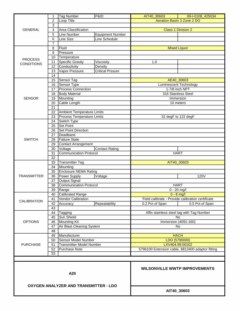
1 Tag Number P&ID AIT40_30603 09-I-0108_4250342345 Line Number Equipment Number6 Line Size Line Schedule789
1011 Specific Gravity Viscosity 1.012 Conductivity Density13 Vapor Pressure Critical Prssure1415161718192021222324252627282930 Voltage Contact Rating313233343536 Power Supply Voltage 120V373839404142 Accuracy Repeatability 0.2 Pct of Span 0.5 Pct of Span4344454647484950515253
Immersion
Aeration Basin 3 Zone 2 DO
Luminescent Technology1-7/8 inch NPT
AE40_30603
32 degF to 122 degF
10 meters
GENERAL
PROCESS CONDITIONS
Mounting316 Stainless Steel
Deadband
Cable Length
Body Material
Communication Protocol
Sensor TagSensor TypeProcess Connection
Transmitter Tag
Communication Protocol
Failure State
TRANSMITTER
SENSOR
CALIBRATION
Calibrated Range
SWITCH
Switch TypeSet Point
Output Signal
PURCHASE
Loop Title
Area Classification
FluidPressureTemperature
Contact Arrangement
Vendor Calibration
Set Point Direction
Tagging
Process Temperature LimitsAmbient Temperature Limits
OPTIONSNo
ManufacturerSensor Model Number
HACH
Class 1 Division 2
Mixed Liquor
Mounting
0 - 8 mg/lField calibrate - Provide calibration certificate
LDO (5790000)
Mounting Kit Immersion (4091-160)Air Blast Cleaning System No
Sun Shield
AIT40_30603
WILSONVILLE WWTP IMPROVEMENTSA20
OXYGEN ANALYZER AND TRANSMITTER - LDO
Enclosure NEMA Rating
LXV404.99.00102Transmitter Model Number5796100 Extension cable, 8813400 adaptor fitting
Range
Affix stainless steel tag with Tag Number
AIT40_30603
HART
Purchase Note
0 - 20 mg/lHART

A30HYDROGEN SULFIDE LOGGER,
PORTABLE
PW/WBG/425034 JANUARY 2014 ©COPYRIGHT 2014 CH2M HILL
INSTRUMENT COMPONENTS40 91 00 SUPPLEMENT

1 Tag Number P&ID AIR91_23001 09-I-0121_42503423456789
101112131415161718192021 CPU: Pump:22 2x 3AA Lithium cell 1x C Alkaline23 2 months 7 days242526272829303132333435363738394041424344454647484950515253
IP54
0 degC to 40 degC, 6 degC/hr max
10 min to 1 hr
15% to 90% non-condensing
Instrument Title
Environmental Protection
Relative Humidity Range
Service
10%
0-2 ppm
SENSOR
Sensor Type
Portable Hydrogen Sulfide Monitor/Logger 1
Foul Air
Purchase Notes:
Temperature Range
PURCHASE
Pressure RangeLogging Interval
CALIBRATION
Battery Type
AIR91_23001
WILSONVILLE WWTP IMPROVEMENTSA30
HYDROGEN SULFIDE GAS ANALYZER, PORTABLE
App-Tek
Yes
Atmospheric +/- 10%
Yes
Yes
Carrying CaseCalibration Kit
Environmental Shelter
Odalog OL50ManufacturerModel
Low-Range Maintenance Kit
Provide calibration certificateAccuracy
OPTIONS Spare Lithium BatteryYesYes
GENERAL
Battery Life
Calibrated Range - Port 1
Vendor Calibration
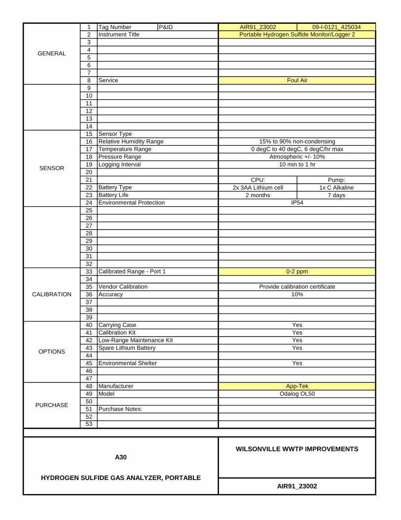
1 Tag Number P&ID AIR91_23002 09-I-0121_42503423456789
101112131415161718192021 CPU: Pump:22 2x 3AA Lithium cell 1x C Alkaline23 2 months 7 days242526272829303132333435363738394041424344454647484950515253
IP54
0 degC to 40 degC, 6 degC/hr max
10 min to 1 hr
15% to 90% non-condensing
Instrument Title
Environmental Protection
Relative Humidity Range
Service
10%
0-2 ppm
SENSOR
Sensor Type
Portable Hydrogen Sulfide Monitor/Logger 2
Foul Air
Purchase Notes:
Temperature Range
PURCHASE
Pressure RangeLogging Interval
CALIBRATION
Battery Type
AIR91_23002
WILSONVILLE WWTP IMPROVEMENTSA30
HYDROGEN SULFIDE GAS ANALYZER, PORTABLE
App-Tek
Yes
Atmospheric +/- 10%
Yes
Yes
Carrying CaseCalibration Kit
Environmental Shelter
Odalog OL50ManufacturerModel
Low-Range Maintenance Kit
Provide calibration certificateAccuracy
OPTIONS Spare Lithium BatteryYesYes
GENERAL
Battery Life
Calibrated Range - Port 1
Vendor Calibration

F04FLOW ELEMENT AND
TRANSMITTER, ELECTROMAGNETIC
PW/WBG/425034 JANUARY 2014 ©COPYRIGHT 2014 CH2M HILL
INSTRUMENT COMPONENTS40 91 00 SUPPLEMENT

1 Tag Number P&ID FIT10_10101 09-I-0101_4250342345 Line Number Equipment Number6 Line Size Line Schedule 18"789
10 Min Flow Max Flow 350 gpm 13900 gpm111213 Specific Gravity Viscosity 1.014 Conductivity Density15 Vapor Pressure Critical Pressure1617181920212223242526272829 Grounding Type Material Grounding Ring303132333435 Power Supply Voltage 4 - Wire 120 VAC3637383940414243 Accuracy Repeatability 0.5 Pct of Span4445464748495051 Grounding Rings Model Number5253
Element Mounting Bracket
FIT10_10101
WILSONVILLE WWTP IMPROVEMENTSF04
FLOW ELEMENT & TRANSMITTER, ELECTROMAGNETIC
Endress + Hauser50W4F-ULGA1RC1BAAA
DK5GD-4FAUL
Element Size 18"
32 degF to 180 degF
Low Flow CutoffAmbient Temperature Limits
ManufacturerModel Number
Process Temperature Limits
Calibrated Range
Purchase Note
Vendor CalibrationTagging
-5 degF to 140 degF
0.033 Feet/Sec
0-14000 gpmHART
Factory calibrate - Provide calibration certificateAffix stainless steel tag with Tag Number
MountingEnclosure NEMA Rating
Output SignalCommunication Protocol
Remote - WallNEMA 4X
4 to 20 madc
PolyurethaneBullet Nose
316SS
NEMA 4X
Electrode MaterialRangeElement Cable Length
Enclosure NEMA RatingMinimum Measurable Velocity
Ambient
Vacuum Possibility No
Electrode Type
FE10_10101
18" Class 1500.5 inch NPT
Stainless Steel
5 psig
Influent RS Flowmeter 1None
OPTIONS
PURCHASE
Nominal PressureNominal Temperature
TRANSMITTER
Process ConnectionElectrical ConnectionTube MaterialLiner Material
GENERAL
PROCESS CONDITIONS
METERING ELEMENT
Raw Sewage
Loop TitleArea Classification
Fluid
Element Tag

1 Tag Number P&ID FIT10_10102 09-I-0101_4250342345 Line Number Equipment Number6 Line Size Line Schedule 10"789
10 Min Flow Max Flow 350 gpm 4200 gpm111213 Specific Gravity Viscosity 1.014 Conductivity Density15 Vapor Pressure Critical Pressure1617181920212223242526272829 Grounding Type Material Grounding Ring303132333435 Power Supply Voltage 4 - Wire 120 VAC3637383940414243 Accuracy Repeatability 0.5 Pct of Span4445464748495051 Grounding Rings Model Number5253
Element Mounting Bracket
FIT10_10102
WILSONVILLE WWTP IMPROVEMENTSF04
FLOW ELEMENT & TRANSMITTER, ELECTROMAGNETIC
Endress + Hauser50W2F-ULGA1RC1BAAA
DK5GD-2FAUL
Element Size 10"
32 degF to 180 degF
Low Flow CutoffAmbient Temperature Limits
ManufacturerModel Number
Process Temperature Limits
Calibrated Range
Purchase Note
Vendor CalibrationTagging
-5 degF to 140 degF
0.033 Feet/Sec
0-4500 gpmHART
Factory calibrate - Provide calibration certificateAffix stainless steel tag with Tag Number
MountingEnclosure NEMA Rating
Output SignalCommunication Protocol
Remote - WallNEMA 4X
4 to 20 madc
PolyurethaneBullet Nose
316SS
NEMA 4X
Electrode MaterialRangeElement Cable Length
Enclosure NEMA RatingMinimum Measurable Velocity
Ambient
Vacuum Possibility No
Electrode Type
FE10_10102
10" Class 1500.5 inch NPT
Stainless Steel
5 psig
Influent RS Flowmeter 2None
OPTIONS
PURCHASE
Nominal PressureNominal Temperature
TRANSMITTER
Process ConnectionElectrical ConnectionTube MaterialLiner Material
GENERAL
PROCESS CONDITIONS
METERING ELEMENT
Raw Sewage
Loop TitleArea Classification
Fluid
Element Tag

1 Tag Number P&ID FIT40_41000 09-I-0113_4250342345 Line Number Equipment Number6 Line Size Line Schedule 3"789
10 Min Flow Max Flow 25 gpm 200 gpm111213 Specific Gravity Viscosity 1.014 Conductivity Density15 Vapor Pressure Critical Pressure1617181920212223242526272829 Grounding Type Material Grounding Ring303132333435 Power Supply Voltage 4 - Wire 120 VAC3637383940414243 Accuracy Repeatability 0.5 Pct of Span4445464748495051 Grounding Rings Model Number5253
GENERAL
PROCESS CONDITIONS
METERING ELEMENT
Waste Activated Sludge
Loop TitleArea Classification
Fluid
Element Tag
OPTIONS
PURCHASE
Nominal PressureNominal Temperature
TRANSMITTER
Process ConnectionElectrical ConnectionTube MaterialLiner Material
8.5 psig
WAS FlowNone
Ambient
Vacuum Possibility No
Electrode Type
FE40_41000
3" Class 1500.5 inch NPT
Stainless Steel
Electrode MaterialRangeElement Cable Length
Enclosure NEMA RatingMinimum Measurable Velocity
TeflonBullet Nose
316SS
NEMA 4X
MountingEnclosure NEMA Rating
Output SignalCommunication Protocol
Remote - StanchionNEMA 4X
4 to 20 madc
-5 degF to 140 degF
0.033 Feet/Sec
0-250 gpmHART
Factory calibrate - Provide calibration certificateAffix stainless steel tag with Tag Number
ManufacturerModel Number
Process Temperature Limits
Calibrated Range
Purchase Note
Vendor CalibrationTagging
Endress + Hauser50P80-ELGA1RC1BAAA
DK5GD-80AEL
Element Size 3"
32 degF to 180 degF
Low Flow CutoffAmbient Temperature Limits
Element Mounting Bracket
FIT40_41000
WILSONVILLE WWTP IMPROVEMENTSF04
FLOW ELEMENT & TRANSMITTER, ELECTROMAGNETIC
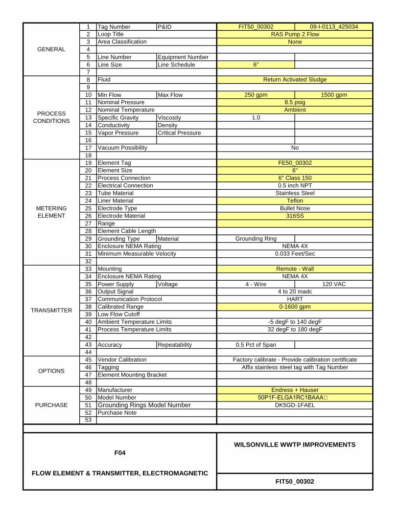
1 Tag Number P&ID FIT50_00302 09-I-0113_4250342345 Line Number Equipment Number6 Line Size Line Schedule 6"789
10 Min Flow Max Flow 250 gpm 1500 gpm111213 Specific Gravity Viscosity 1.014 Conductivity Density15 Vapor Pressure Critical Pressure1617181920212223242526272829 Grounding Type Material Grounding Ring303132333435 Power Supply Voltage 4 - Wire 120 VAC3637383940414243 Accuracy Repeatability 0.5 Pct of Span4445464748495051 Grounding Rings Model Number5253
Element Mounting Bracket
FIT50_00302
WILSONVILLE WWTP IMPROVEMENTSF04
FLOW ELEMENT & TRANSMITTER, ELECTROMAGNETIC
Endress + Hauser50P1F-ELGA1RC1BAAA
DK5GD-1FAEL
Element Size 6"
32 degF to 180 degF
Low Flow CutoffAmbient Temperature Limits
ManufacturerModel Number
Process Temperature Limits
Calibrated Range
Purchase Note
Vendor CalibrationTagging
-5 degF to 140 degF
0.033 Feet/Sec
0-1600 gpmHART
Factory calibrate - Provide calibration certificateAffix stainless steel tag with Tag Number
MountingEnclosure NEMA Rating
Output SignalCommunication Protocol
Remote - WallNEMA 4X
4 to 20 madc
TeflonBullet Nose
316SS
NEMA 4X
Electrode MaterialRangeElement Cable Length
Enclosure NEMA RatingMinimum Measurable Velocity
Ambient
Vacuum Possibility No
Electrode Type
FE50_00302
6" Class 1500.5 inch NPT
Stainless Steel
8.5 psig
RAS Pump 2 FlowNone
OPTIONS
PURCHASE
Nominal PressureNominal Temperature
TRANSMITTER
Process ConnectionElectrical ConnectionTube MaterialLiner Material
GENERAL
PROCESS CONDITIONS
METERING ELEMENT
Return Activated Sludge
Loop TitleArea Classification
Fluid
Element Tag

1 Tag Number P&ID FIT50_00304 09-I-0113_4250342345 Line Number Equipment Number6 Line Size Line Schedule 6"789
10 Min Flow Max Flow 250 gpm 1500 gpm111213 Specific Gravity Viscosity 1.014 Conductivity Density15 Vapor Pressure Critical Pressure1617181920212223242526272829 Grounding Type Material Grounding Ring303132333435 Power Supply Voltage 4 - Wire 120 VAC3637383940414243 Accuracy Repeatability 0.5 Pct of Span4445464748495051 Grounding Rings Model Number5253
Element Mounting Bracket
FIT50_00304
WILSONVILLE WWTP IMPROVEMENTSF04
FLOW ELEMENT & TRANSMITTER, ELECTROMAGNETIC
Endress + Hauser50P1F-ELGA1RC1BAAA
DK5GD-1FAEL
Element Size 6"
32 degF to 180 degF
Low Flow CutoffAmbient Temperature Limits
ManufacturerModel Number
Process Temperature Limits
Calibrated Range
Purchase Note
Vendor CalibrationTagging
-5 degF to 140 degF
0.033 Feet/Sec
0-1600 gpmHART
Factory calibrate - Provide calibration certificateAffix stainless steel tag with Tag Number
MountingEnclosure NEMA Rating
Output SignalCommunication Protocol
Remote - WallNEMA 4X
4 to 20 madc
TeflonBullet Nose
316SS
NEMA 4X
Electrode MaterialRangeElement Cable Length
Enclosure NEMA RatingMinimum Measurable Velocity
Ambient
Vacuum Possibility No
Electrode Type
FE50_00304
6" Class 1500.5 inch NPT
Stainless Steel
8.5 psig
RAS Pump 4 FlowNone
OPTIONS
PURCHASE
Nominal PressureNominal Temperature
TRANSMITTER
Process ConnectionElectrical ConnectionTube MaterialLiner Material
GENERAL
PROCESS CONDITIONS
METERING ELEMENT
Return Activated Sludge
Loop TitleArea Classification
Fluid
Element Tag

1 Tag Number P&ID FIT70_20500 09-I-0118_4250342345 Line Number Equipment Number6 Line Size Line Schedule 24"789
10 Min Flow Max Flow 350 gpm 5500 gpm111213 Specific Gravity Viscosity 1.014 Conductivity Density15 Vapor Pressure Critical Pressure1617181920212223242526272829 Grounding Type Material Grounding Ring303132333435 Power Supply Voltage 4 - Wire 120 VAC3637383940414243 Accuracy Repeatability 0.5 Pct of Span4445464748495051 Grounding Rings Model Number5253
GENERAL
PROCESS CONDITIONS
METERING ELEMENT
Secondary/Final Effluent
Loop TitleArea Classification
Fluid
Element Tag
OPTIONS
PURCHASE
Nominal PressureNominal Temperature
TRANSMITTER
Process ConnectionElectrical ConnectionTube MaterialLiner Material
25 psig
UV Channel 2 FlowNone
Ambient
Vacuum Possibility No
Electrode Type
FE70_20500
24" Class 1500.5 inch NPT
Stainless Steel
Electrode MaterialRangeElement Cable Length
Enclosure NEMA RatingMinimum Measurable Velocity
PolyurethaneBullet Nose
316SS
50'
NEMA 6P (Submersible)
MountingEnclosure NEMA Rating
Output SignalCommunication Protocol
Remote - StanchionNEMA 4X
4 to 20 madc
-5 degF to 140 degF
50' cable
0.033 Feet/Sec
0-6000 gpmHART
Factory calibrate - Provide calibration certificateAffix stainless steel tag with Tag Number
ManufacturerModel Number
Process Temperature Limits
Calibrated Range
Purchase Note
Vendor CalibrationTagging
Endress + Hauser50W6H-ULGA1RK5BAAA
DK5GD-6HAUL
Element Size 24"
32 degF to 180 degF
Low Flow CutoffAmbient Temperature Limits
Element Mounting Bracket
FIT70_20500
WILSONVILLE WWTP IMPROVEMENTSF04
FLOW ELEMENT & TRANSMITTER, ELECTROMAGNETIC
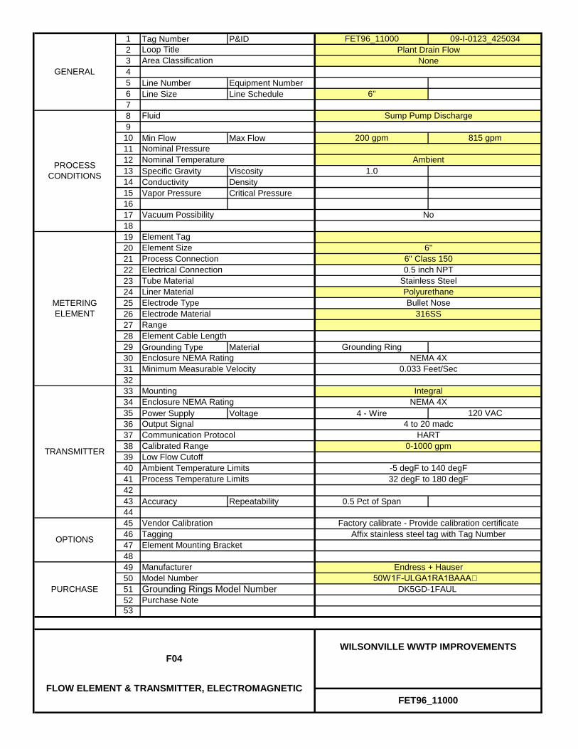
1 Tag Number P&ID FET96_11000 09-I-0123_4250342345 Line Number Equipment Number6 Line Size Line Schedule 6"789
10 Min Flow Max Flow 200 gpm 815 gpm111213 Specific Gravity Viscosity 1.014 Conductivity Density15 Vapor Pressure Critical Pressure1617181920212223242526272829 Grounding Type Material Grounding Ring303132333435 Power Supply Voltage 4 - Wire 120 VAC3637383940414243 Accuracy Repeatability 0.5 Pct of Span4445464748495051 Grounding Rings Model Number5253
GENERAL
PROCESS CONDITIONS
METERING ELEMENT
Sump Pump Discharge
Loop TitleArea Classification
Fluid
Element Tag
OPTIONS
PURCHASE
Nominal PressureNominal Temperature
TRANSMITTER
Process ConnectionElectrical ConnectionTube MaterialLiner Material
Plant Drain FlowNone
Ambient
Vacuum Possibility No
Electrode Type
6" Class 1500.5 inch NPT
Stainless Steel
Electrode MaterialRangeElement Cable Length
Enclosure NEMA RatingMinimum Measurable Velocity
PolyurethaneBullet Nose
316SS
NEMA 4X
MountingEnclosure NEMA Rating
Output SignalCommunication Protocol
IntegralNEMA 4X
4 to 20 madc
-5 degF to 140 degF
0.033 Feet/Sec
0-1000 gpmHART
Factory calibrate - Provide calibration certificateAffix stainless steel tag with Tag Number
ManufacturerModel Number
Process Temperature Limits
Calibrated Range
Purchase Note
Vendor CalibrationTagging
Endress + Hauser50W1F-ULGA1RA1BAAA
DK5GD-1FAUL
Element Size 6"
32 degF to 180 degF
Low Flow CutoffAmbient Temperature Limits
Element Mounting Bracket
FET96_11000
WILSONVILLE WWTP IMPROVEMENTSF04
FLOW ELEMENT & TRANSMITTER, ELECTROMAGNETIC
F16ROTAMETER
PW/WBG/425034 JANUARY 2014 ©COPYRIGHT 2014 CH2M HILL
INSTRUMENT COMPONENTS40 91 00 SUPPLEMENT
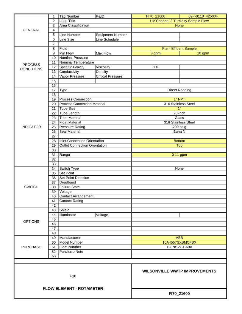
1 Tag Number P&ID FI70_21600 09-I-0118_4250342345 Line Number Equipment Number6 Line Size Line Schedule789 Min Flow Max Flow 3 gpm 10 gpm
101112 Specific Gravity Viscosity 1.013 Conductivity Density14 Vapor Pressure Critical Pressure151617181920212223242526272829303132333435363738394041424344 Illuminator Voltage454647484950515253
OPTIONS
Set Point Direction
Model NumberFloat Number
SWITCH
Set Point
GENERAL
PROCESS CONDITIONS
INDICATOR
DeadbandFailure State
Loop TitleArea Classification
PURCHASE
Nominal PressureNominal Temperature
Process ConnectionProcess Connection Material
Manufacturer
Purchase Note
200 psig
Tube Size
Fluid
Outlet Connection Orientation
Pressure RatingSeal Material
Inlet Connection Orientation
Type
UV Channel 2 Turbidity Sample FlowNone
Direct Reading
Plant Effluent Sample
Range
Tube LengthTube MaterialFloat Material
1" NPT316 Stainless Steel
Buna N
1"20-inchGlass
316 Stainless Steel
Switch Type None
Bottom
0-11 gpm
Top
Voltage
Contact Rating
Shield
Contact Arrangement
ABB10A4557SXBMCFBX
1-GNSVGT-69A
FI70_21600
WILSONVILLE WWTP IMPROVEMENTSF16
FLOW ELEMENT - ROTAMETER

F51FLOW ELEMENT AND TRANSMITTER,
THERMAL MASS FLOW
PW/WBG/425034 JANUARY 2014 ©COPYRIGHT 2014 CH2M HILL
INSTRUMENT COMPONENTS40 91 00 SUPPLEMENT

1 Tag Number P&ID FIT40_12001 09-I-0105_4250342345 Line Number Equipment Number6 Line Size Line Schedule 12" 10S789
10 Min Flow Max Flow 160 scfm 2000 scfm111213 Specific Gravity Viscosity14 Conductivity Density15 Vapor Pressure Critical Pressure161718192021222324252627282930313233 Power Supply Voltage 4 - Wire 120 VAC34353637383940414243 Accuracy Repeatability 1.5 Pct of Range 0.5 Pct44454647484950515253
Meter Size
FIT40_12001
WILSONVILLE WWTP IMPROVEMENTSF51
FLOW ELEMENT & TRANSMITTER, THERMAL MASS FLOW
Purchase Note
Affix stainless steel tag with Tag Number
VIP-AA12.39SFCI
ST98-23NN022CCAF
Flow Conditioner ModelManufacturer
Tagging
-5 degF to 140 degF
0.75 - 600 sfps
Ambient Temperature Limits
Range-40 degF to 212 degF
Enclosure NEMA Rating
Output SignalCommunication Protocol
Remote, StanchionNEMA 4X
4 to 20 madcHART
Mounting
Process Temperature Limits
FE40_12001
6.5"1 inch NPT
316 Stainless Steel
Mounting OrientationElement Cable LengthElement Range
No
6.8 psi
Horiz, top, left to right
OPTIONS
PURCHASE
PressureTemperature
TRANSMITTER
Vacuum Possibility
Process Temperature Limits
Model Number
GENERAL
PROCESS CONDITIONS
ELEMENT
Element Tag
Stabilization Basin 1 Air FlowNone
150F
Air Low Pressure
Loop TitleArea Classification
Fluid
Insertion LengthProcess ConnectionWetted Material
Flow Conditioner Tag FY40_12001
CALIBRATION
Calibrated RangeVendor Calibration
0-2200 scfmFactory calibrate - Provide calibration certificate

1 Tag Number P&ID FIT40_12002 09-I-0105_4250342345 Line Number Equipment Number6 Line Size Line Schedule 12" 10S789
10 Min Flow Max Flow 160 scfm 2000 scfm111213 Specific Gravity Viscosity14 Conductivity Density15 Vapor Pressure Critical Pressure161718192021222324252627282930313233 Power Supply Voltage 4 - Wire 120 VAC34353637383940414243 Accuracy Repeatability 1.5 Pct of Range 0.5 Pct44454647484950515253
Flow Conditioner Tag FY40_12002
CALIBRATION
Calibrated RangeVendor Calibration
0-2200 scfmFactory calibrate - Provide calibration certificate
Air Low Pressure
Loop TitleArea Classification
Fluid
Insertion LengthProcess ConnectionWetted Material
GENERAL
PROCESS CONDITIONS
ELEMENT
Element Tag
Stabilization Basin 2 Air FlowNone
150F
OPTIONS
PURCHASE
PressureTemperature
TRANSMITTER
Vacuum Possibility
Process Temperature Limits
Model Number
No
6.8 psi
Horiz, top, right to leftMounting OrientationElement Cable LengthElement Range
Mounting
Process Temperature Limits
FE40_12002
6.5"1 inch NPT
316 Stainless Steel
Enclosure NEMA Rating
Output SignalCommunication Protocol
Remote, StanchionNEMA 4X
4 to 20 madcHART
Tagging
-5 degF to 140 degF
0.75 - 600 sfps
Ambient Temperature Limits
Range-40 degF to 212 degF
Purchase Note
Affix stainless steel tag with Tag Number
VIP-AA12.39SFCI
ST98-13NN022CCAF
Flow Conditioner ModelManufacturer
Meter Size
FIT40_12002
WILSONVILLE WWTP IMPROVEMENTSF51
FLOW ELEMENT & TRANSMITTER, THERMO MASS FLOW

1 Tag Number P&ID FIT40_30001 09-I-0108_4250342345 Line Number Equipment Number6 Line Size Line Schedule 8" 10S789
10 Min Flow Max Flow 90 scfm 1100 scfm111213 Specific Gravity Viscosity14 Conductivity Density15 Vapor Pressure Critical Pressure161718192021222324252627282930313233 Power Supply Voltage 4 - Wire 120 VAC34353637383940414243 Accuracy Repeatability 1.5 Pct of Range 0.5 Pct44454647484950515253
Flow Conditioner Tag FY40_30001
CALIBRATION
Calibrated RangeVendor Calibration
0-1200 scfmFactory calibrate - Provide calibration certificate
Air Low Pressure
Loop TitleArea Classification
Fluid
Insertion LengthProcess ConnectionWetted Material
GENERAL
PROCESS CONDITIONS
ELEMENT
Element Tag
Aeration Basin 1 Zone 1 Air FlowNone
150F
OPTIONS
PURCHASE
PressureTemperature
TRANSMITTER
Vacuum Possibility
Process Temperature Limits
Model Number
No
6.8 psi
Horiz, top, left to rightMounting OrientationElement Cable LengthElement Range
Mounting
Process Temperature Limits
FE40_30001
4.5"1 inch NPT
316 Stainless Steel
Enclosure NEMA Rating
Output SignalCommunication Protocol
Remote, StanchionNEMA 4X
4 to 20 madcHART
Tagging
-5 degF to 140 degF
0.75 - 600 sfps
Ambient Temperature Limits
Range-40 degF to 212 degF
Purchase Note
Affix stainless steel tag with Tag Number
VIP-AA08.33SFCI
ST98-23NN012CCAF
Flow Conditioner ModelManufacturer
Meter Size
FIT40_30001
WILSONVILLE WWTP IMPROVEMENTSF51
FLOW ELEMENT & TRANSMITTER, THERMO MASS FLOW

1 Tag Number P&ID FIT40_30002 09-I-0108_4250342345 Line Number Equipment Number6 Line Size Line Schedule 8" 10S789
10 Min Flow Max Flow 90 scfm 1100 scfm111213 Specific Gravity Viscosity14 Conductivity Density15 Vapor Pressure Critical Pressure161718192021222324252627282930313233 Power Supply Voltage 4 - Wire 120 VAC34353637383940414243 Accuracy Repeatability 1.5 Pct of Range 0.5 Pct44454647484950515253
Meter Size
FIT40_30002
WILSONVILLE WWTP IMPROVEMENTSF51
FLOW ELEMENT & TRANSMITTER, THERMO MASS FLOW
Purchase Note
Affix stainless steel tag with Tag Number
VIP-AA08.33SFCI
ST98-13NN012CCAF
Flow Conditioner ModelManufacturer
Tagging
-5 degF to 140 degF
0.75 - 600 sfps
Ambient Temperature Limits
Range-40 degF to 212 degF
Enclosure NEMA Rating
Output SignalCommunication Protocol
Remote, StanchionNEMA 4X
4 to 20 madcHART
Mounting
Process Temperature Limits
FE40_30002
4.5"1 inch NPT
316 Stainless Steel
Mounting OrientationElement Cable LengthElement Range
No
6.8 psi
Horiz, top, right to left
OPTIONS
PURCHASE
PressureTemperature
TRANSMITTER
Vacuum Possibility
Process Temperature Limits
Model Number
GENERAL
PROCESS CONDITIONS
ELEMENT
Element Tag
Aeration Basin 2 Zone 1 Air FlowNone
150F
Air Low Pressure
Loop TitleArea Classification
Fluid
Insertion LengthProcess ConnectionWetted Material
Flow Conditioner Tag FY40_30002
CALIBRATION
Calibrated RangeVendor Calibration
0-1200 scfmFactory calibrate - Provide calibration certificate

1 Tag Number P&ID FIT40_30003 09-I-0108_4250342345 Line Number Equipment Number6 Line Size Line Schedule 8" 10S789
10 Min Flow Max Flow 90 scfm 1100 scfm111213 Specific Gravity Viscosity14 Conductivity Density15 Vapor Pressure Critical Pressure161718192021222324252627282930313233 Power Supply Voltage 4 - Wire 120 VAC34353637383940414243 Accuracy Repeatability 1.5 Pct of Range 0.5 Pct44454647484950515253
Meter Size
FIT40_30003
WILSONVILLE WWTP IMPROVEMENTSF51
FLOW ELEMENT & TRANSMITTER, THERMO MASS FLOW
Purchase Note
Affix stainless steel tag with Tag Number
VIP-AA08.33SFCI
ST98-23NN012CCAF
Flow Conditioner ModelManufacturer
Tagging
-5 degF to 140 degF
0.75 - 600 sfps
Ambient Temperature Limits
Range-40 degF to 212 degF
Enclosure NEMA Rating
Output SignalCommunication Protocol
Remote, StanchionNEMA 4X
4 to 20 madcHART
Mounting
Process Temperature Limits
FE40_30003
4.5"1 inch NPT
316 Stainless Steel
Mounting OrientationElement Cable LengthElement Range
No
6.8 psi
Horiz, top, left to right
OPTIONS
PURCHASE
PressureTemperature
TRANSMITTER
Vacuum Possibility
Process Temperature Limits
Model Number
GENERAL
PROCESS CONDITIONS
ELEMENT
Element Tag
Aeration Basin 3 Zone 1 Air FlowNone
150F
Air Low Pressure
Loop TitleArea Classification
Fluid
Insertion LengthProcess ConnectionWetted Material
Flow Conditioner Tag FY40_30003
CALIBRATION
Calibrated RangeVendor Calibration
0-1200 scfmFactory calibrate - Provide calibration certificate

1 Tag Number P&ID FIT40_30101 09-I-0108_4250342345 Line Number Equipment Number6 Line Size Line Schedule 8" 10S789
10 Min Flow Max Flow 300 scfm 800 scfm111213 Specific Gravity Viscosity14 Conductivity Density15 Vapor Pressure Critical Pressure161718192021222324252627282930313233 Power Supply Voltage 4 - Wire 120 VAC34353637383940414243 Accuracy Repeatability 1.5 Pct of Range 0.5 Pct44454647484950515253
Flow Conditioner Tag FY40_30101
CALIBRATION
Calibrated RangeVendor Calibration
0-1200 scfmFactory calibrate - Provide calibration certificate
Air Low Pressure
Loop TitleArea Classification
Fluid
Insertion LengthProcess ConnectionWetted Material
GENERAL
PROCESS CONDITIONS
ELEMENT
Element Tag
Aeration Basin 1 Zone 2 Air FlowNone
150F
OPTIONS
PURCHASE
PressureTemperature
TRANSMITTER
Vacuum Possibility
Process Temperature Limits
Model Number
No
6.8 psi
Horiz, top, right to leftMounting OrientationElement Cable LengthElement Range
Mounting
Process Temperature Limits
FE40_30101
4.5"1 inch NPT
316 Stainless Steel
Enclosure NEMA Rating
Output SignalCommunication Protocol
Remote, StanchionNEMA 4X
4 to 20 madcHART
Tagging
-5 degF to 140 degF
0.75 - 600 sfps
Ambient Temperature Limits
Range-40 degF to 212 degF
Purchase Note
Affix stainless steel tag with Tag Number
VIP-AA08.33SFCI
ST98-13NN012CCAF
Flow Conditioner ModelManufacturer
Meter Size
FIT40_30101
WILSONVILLE WWTP IMPROVEMENTSF51
FLOW ELEMENT & TRANSMITTER, THERMO MASS FLOW

1 Tag Number P&ID FIT40_30102 09-I-0108_4250342345 Line Number Equipment Number6 Line Size Line Schedule 8" 10S789
10 Min Flow Max Flow 300 scfm 800 scfm111213 Specific Gravity Viscosity14 Conductivity Density15 Vapor Pressure Critical Pressure161718192021222324252627282930313233 Power Supply Voltage 4 - Wire 120 VAC34353637383940414243 Accuracy Repeatability 1.5 Pct of Range 0.5 Pct44454647484950515253
Flow Conditioner Tag FY40_30102
CALIBRATION
Calibrated RangeVendor Calibration
0-1200 scfmFactory calibrate - Provide calibration certificate
Air Low Pressure
Loop TitleArea Classification
Fluid
Insertion LengthProcess ConnectionWetted Material
GENERAL
PROCESS CONDITIONS
ELEMENT
Element Tag
Aeration Basin 2 Zone 2 Air FlowNone
150F
OPTIONS
PURCHASE
PressureTemperature
TRANSMITTER
Vacuum Possibility
Process Temperature Limits
Model Number
No
6.8 psi
Horiz, top, left to rightMounting OrientationElement Cable LengthElement Range
Mounting
Process Temperature Limits
FE40_30102
4.5"1 inch NPT
316 Stainless Steel
Enclosure NEMA Rating
Output SignalCommunication Protocol
Remote, StanchionNEMA 4X
4 to 20 madcHART
Tagging
-5 degF to 140 degF
0.75 - 600 sfps
Ambient Temperature Limits
Range-40 degF to 212 degF
Purchase Note
Affix stainless steel tag with Tag Number
VIP-AA08.33SFCI
ST98-23NN012CCAF
Flow Conditioner ModelManufacturer
Meter Size
FIT40_30102
WILSONVILLE WWTP IMPROVEMENTSF51
FLOW ELEMENT & TRANSMITTER, THERMO MASS FLOW
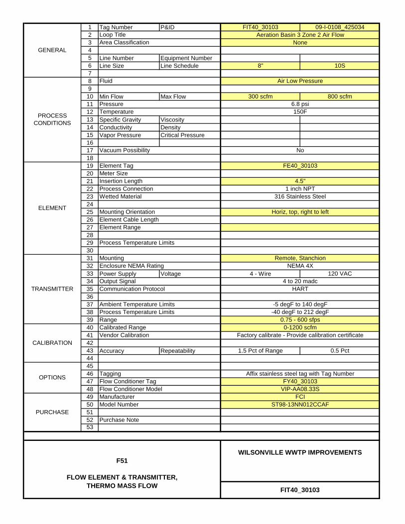
1 Tag Number P&ID FIT40_30103 09-I-0108_4250342345 Line Number Equipment Number6 Line Size Line Schedule 8" 10S789
10 Min Flow Max Flow 300 scfm 800 scfm111213 Specific Gravity Viscosity14 Conductivity Density15 Vapor Pressure Critical Pressure161718192021222324252627282930313233 Power Supply Voltage 4 - Wire 120 VAC34353637383940414243 Accuracy Repeatability 1.5 Pct of Range 0.5 Pct44454647484950515253
Flow Conditioner Tag FY40_30103
CALIBRATION
Calibrated RangeVendor Calibration
0-1200 scfmFactory calibrate - Provide calibration certificate
Air Low Pressure
Loop TitleArea Classification
Fluid
Insertion LengthProcess ConnectionWetted Material
GENERAL
PROCESS CONDITIONS
ELEMENT
Element Tag
Aeration Basin 3 Zone 2 Air FlowNone
150F
OPTIONS
PURCHASE
PressureTemperature
TRANSMITTER
Vacuum Possibility
Process Temperature Limits
Model Number
No
6.8 psi
Horiz, top, right to leftMounting OrientationElement Cable LengthElement Range
Mounting
Process Temperature Limits
FE40_30103
4.5"1 inch NPT
316 Stainless Steel
Enclosure NEMA Rating
Output SignalCommunication Protocol
Remote, StanchionNEMA 4X
4 to 20 madcHART
Tagging
-5 degF to 140 degF
0.75 - 600 sfps
Ambient Temperature Limits
Range-40 degF to 212 degF
Purchase Note
Affix stainless steel tag with Tag Number
VIP-AA08.33SFCI
ST98-13NN012CCAF
Flow Conditioner ModelManufacturer
Meter Size
FIT40_30103
WILSONVILLE WWTP IMPROVEMENTSF51
FLOW ELEMENT & TRANSMITTER, THERMO MASS FLOW

L08LEVEL SWITCH, FLOAT
PW/WBG/425034 JANUARY 2014 ©COPYRIGHT 2014 CH2M HILL
INSTRUMENT COMPONENTS40 91 00 SUPPLEMENT

1 Tag Number P&ID LSH10_10600 09-I-0101_4250342345 Line Number Equipment Number6 Line Size Line Schedule789
1011 Specific Gravity Viscosity12 Conductivity Density13 Vapor Pressure Critical Pressure14151617181920212223242526272829303132333435363738394041424344454647484950515253
SWITCH
Set Point
Contact Arrangement
DeadbandRising
Polypropylene
No
PROCESS CONDITIONS
CALIBRATION
ELEMENT
Wetted Materials
Vendor Calibration
OPTIONS
TaggingPipe Mounting Clamp
GENERAL
Communication Protocol
Switch Type
Process Temperature Limits
SPDNone
Sump Pump Discharge
PURCHASE
ServiceArea Classification
FluidAtmospheric
Element TypeCable Length
Float30 Feet
PressureTemperature
Manufacturer
Affix stainless steel tag with Tag NumberYesNoNo
Voltage
Purchase Note
SiemensW2T277360
120 VAC
Contact Rating 4.5 Amps
LSH10_10600
WILSONVILLE WWTP IMPROVEMENTSL08
LEVEL SWITCH - FLOAT
Cable/Weight Suspension KitInternal Weight Suspension Kit
Model Number
SPST
Set Point Direction
Ambient Temperature Limits
Relay Output
Normally Open
113.5 ft. el.
Failure State

1 Tag Number P&ID LSL10_10600 09-I-0101_4250342345 Line Number Equipment Number6 Line Size Line Schedule789
1011 Specific Gravity Viscosity12 Conductivity Density13 Vapor Pressure Critical Pressure14151617181920212223242526272829303132333435363738394041424344454647484950515253
YesNoNo
SPST
Set Point Direction
Ambient Temperature Limits
Relay Output
LSL10_10600
WILSONVILLE WWTP IMPROVEMENTSL08
LEVEL SWITCH - FLOAT
Cable/Weight Suspension KitInternal Weight Suspension Kit
Model Number
Normally OpenVoltage
Purchase Note
SiemensW2T277360
120 VAC
Contact Rating
111.5 ft. el.
4.5 Amps
Manufacturer
Affix stainless steel tag with Tag Number
Failure State
Atmospheric
Element TypeCable Length
Float30 Feet
PressureTemperature
SPDNone
Sump Pump Discharge
PURCHASE
ServiceArea Classification
Fluid
Vendor Calibration
OPTIONS
TaggingPipe Mounting Clamp
GENERAL
Communication Protocol
Switch Type
Process Temperature Limits
PROCESS CONDITIONS
CALIBRATION
ELEMENT
Wetted Materials Polypropylene
No
SWITCH
Set Point
Contact Arrangement
DeadbandFalling

1 Tag Number P&ID LSH10_12100 09-I-0101_4250342345 Line Number Equipment Number6 Line Size Line Schedule789
1011 Specific Gravity Viscosity12 Conductivity Density13 Vapor Pressure Critical Pressure14151617181920212223242526272829303132333435363738394041424344454647484950515253
SWITCH
Set Point
Contact Arrangement
DeadbandRising
Polypropylene
No
PROCESS CONDITIONS
CALIBRATION
ELEMENT
Wetted Materials
Vendor Calibration
OPTIONS
TaggingPipe Mounting Clamp
GENERAL
Communication Protocol
Switch Type
Process Temperature Limits
RSClass 1, Div. 2
Raw Sewage
PURCHASE
ServiceArea Classification
FluidAtmospheric
Element TypeCable Length
Float30 Feet
PressureTemperature
Manufacturer
Affix stainless steel tag with Tag NumberYesNoNo
Voltage
Purchase Note
SiemensW2T277360
120 VAC
Contact Rating 4.5 Amps
LSH10_12100
WILSONVILLE WWTP IMPROVEMENTSL08
LEVEL SWITCH - FLOAT
Cable/Weight Suspension KitInternal Weight Suspension Kit
Model Number
SPST
Set Point Direction
Ambient Temperature Limits
Relay Output
Normally Open
121.0 ft. el
Failure State

1 Tag Number P&ID LSH53_11000 09-I-0115_4250342345 Line Number Equipment Number6 Line Size Line Schedule789
1011 Specific Gravity Viscosity12 Conductivity Density13 Vapor Pressure Critical Pressure14151617181920212223242526272829303132333435363738394041424344454647484950515253
YesNoNo
SPST
Set Point Direction
Ambient Temperature Limits
Relay Output
LSH53_11000
WILSONVILLE WWTP IMPROVEMENTSL08
LEVEL SWITCH - FLOAT
Cable/Weight Suspension KitInternal Weight Suspension Kit
Model Number
Normally OpenVoltage
Purchase Note
SiemensW2T277360
120 VAC
Contact Rating
105.0 ft. el.
4.5 Amps
Manufacturer
Affix stainless steel tag with Tag Number
Failure State
Atmospheric
Element TypeCable Length
Float30 Feet
PressureTemperature
SENone
Secondary Effluent
PURCHASE
ServiceArea Classification
Fluid
Vendor Calibration
OPTIONS
TaggingPipe Mounting Clamp
GENERAL
Communication Protocol
Switch Type
Process Temperature Limits
PROCESS CONDITIONS
CALIBRATION
ELEMENT
Wetted Materials Polypropylene
No
SWITCH
Set Point
Contact Arrangement
DeadbandRising
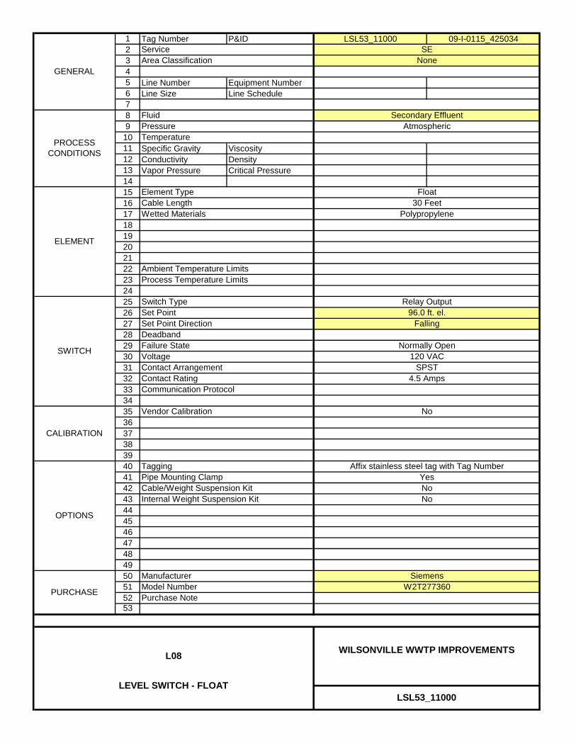
1 Tag Number P&ID LSL53_11000 09-I-0115_4250342345 Line Number Equipment Number6 Line Size Line Schedule789
1011 Specific Gravity Viscosity12 Conductivity Density13 Vapor Pressure Critical Pressure14151617181920212223242526272829303132333435363738394041424344454647484950515253
YesNoNo
SPST
Set Point Direction
Ambient Temperature Limits
Relay Output
LSL53_11000
WILSONVILLE WWTP IMPROVEMENTSL08
LEVEL SWITCH - FLOAT
Cable/Weight Suspension KitInternal Weight Suspension Kit
Model Number
Normally OpenVoltage
Purchase Note
SiemensW2T277360
120 VAC
Contact Rating
96.0 ft. el.
4.5 Amps
Manufacturer
Affix stainless steel tag with Tag Number
Failure State
Atmospheric
Element TypeCable Length
Float30 Feet
PressureTemperature
SENone
Secondary Effluent
PURCHASE
ServiceArea Classification
Fluid
Vendor Calibration
OPTIONS
TaggingPipe Mounting Clamp
GENERAL
Communication Protocol
Switch Type
Process Temperature Limits
PROCESS CONDITIONS
CALIBRATION
ELEMENT
Wetted Materials Polypropylene
No
SWITCH
Set Point
Contact Arrangement
DeadbandFalling

1 Tag Number P&ID LSH55_11201 09-I-0116_4250342345 Line Number Equipment Number6 Line Size Line Schedule789
1011 Specific Gravity Viscosity12 Conductivity Density13 Vapor Pressure Critical Pressure14151617181920212223242526272829303132333435363738394041424344454647484950515253
SPST
Set Point Direction
Ambient Temperature Limits
Relay Output
Normally Open
117.0 ft. el
Failure State
LSH55_11201
WILSONVILLE WWTP IMPROVEMENTSL08
LEVEL SWITCH - FLOAT
Cable/Weight Suspension KitInternal Weight Suspension Kit
Supply SS Wall Mounts for 1" PipeModel Number
Voltage
Purchase Note
Anchor ScientificP30NO
120 VAC
Contact Rating 4.5 Amps
Manufacturer
Affix stainless steel tag with Tag NumberYesNoNo
Atmospheric
Element TypeCable Length
Float30 Feet
PressureTemperature
SENone
Secondary Effluent
PURCHASE
ServiceArea Classification
Fluid
Vendor Calibration
OPTIONS
TaggingPipe Mounting Clamp
GENERAL
Communication Protocol
Switch Type
Process Temperature Limits
PROCESS CONDITIONS
CALIBRATION
ELEMENT
Wetted Materials Polypropylene
No
SWITCH
Set Point
Contact Arrangement
DeadbandRising
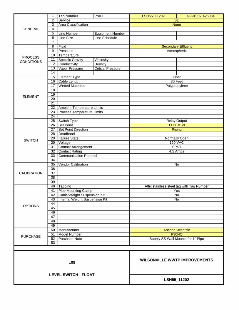
1 Tag Number P&ID LSH55_11202 09-I-0116_4250342345 Line Number Equipment Number6 Line Size Line Schedule789
1011 Specific Gravity Viscosity12 Conductivity Density13 Vapor Pressure Critical Pressure14151617181920212223242526272829303132333435363738394041424344454647484950515253
SPST
Set Point Direction
Ambient Temperature Limits
Relay Output
Normally Open
117.0 ft. el
Failure State
LSH55_11202
WILSONVILLE WWTP IMPROVEMENTSL08
LEVEL SWITCH - FLOAT
Cable/Weight Suspension KitInternal Weight Suspension Kit
Supply SS Wall Mounts for 1" PipeModel Number
Voltage
Purchase Note
Anchor ScientificP30NO
120 VAC
Contact Rating 4.5 Amps
Manufacturer
Affix stainless steel tag with Tag NumberYesNoNo
Atmospheric
Element TypeCable Length
Float30 Feet
PressureTemperature
SENone
Secondary Effluent
PURCHASE
ServiceArea Classification
Fluid
Vendor Calibration
OPTIONS
TaggingPipe Mounting Clamp
GENERAL
Communication Protocol
Switch Type
Process Temperature Limits
PROCESS CONDITIONS
CALIBRATION
ELEMENT
Wetted Materials Polypropylene
No
SWITCH
Set Point
Contact Arrangement
DeadbandRising

1 Tag Number P&ID LSH78_40200 09-I-0132_4250342345 Line Number Equipment Number6 Line Size Line Schedule789
1011 Specific Gravity Viscosity12 Conductivity Density13 Vapor Pressure Critical Pressure14151617181920212223242526272829303132333435363738394041424344454647484950515253
YesNoNo
SPST
Set Point Direction
Ambient Temperature Limits
Relay Output
LSH78_40200
WILSONVILLE WWTP IMPROVEMENTSL08
LEVEL SWITCH - FLOAT
Cable/Weight Suspension KitInternal Weight Suspension Kit
Model Number
Normally OpenVoltage
Purchase Note
SiemensW2T277360
120 VAC
Contact Rating
112.5 ft. el.
4.5 Amps
Manufacturer
Affix stainless steel tag with Tag Number
Failure State
Atmospheric
Element TypeCable Length
Float30 Feet
PressureTemperature
DC/DRClass 2, Div. 2
Dryer Condensate Drain
PURCHASE
ServiceArea Classification
Fluid
Vendor Calibration
OPTIONS
TaggingPipe Mounting Clamp
GENERAL
Communication Protocol
Switch Type
Process Temperature Limits
PROCESS CONDITIONS
CALIBRATION
ELEMENT
Wetted Materials Polypropylene
No
SWITCH
Set Point
Contact Arrangement
DeadbandRising
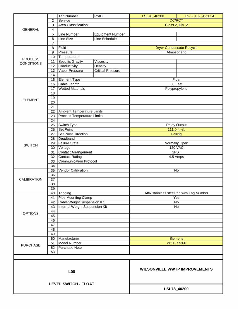
1 Tag Number P&ID LSL78_40200 09-I-0132_4250342345 Line Number Equipment Number6 Line Size Line Schedule789
1011 Specific Gravity Viscosity12 Conductivity Density13 Vapor Pressure Critical Pressure14151617181920212223242526272829303132333435363738394041424344454647484950515253
YesNoNo
SPST
Set Point Direction
Ambient Temperature Limits
Relay Output
LSL78_40200
WILSONVILLE WWTP IMPROVEMENTSL08
LEVEL SWITCH - FLOAT
Cable/Weight Suspension KitInternal Weight Suspension Kit
Model Number
Normally OpenVoltage
Purchase Note
SiemensW2T277360
120 VAC
Contact Rating
111.0 ft. el.
4.5 Amps
Manufacturer
Affix stainless steel tag with Tag Number
Failure State
Atmospheric
Element TypeCable Length
Float30 Feet
PressureTemperature
DC/RCYClass 2, Div. 2
Dryer Condensate Recycle
PURCHASE
ServiceArea Classification
Fluid
Vendor Calibration
OPTIONS
TaggingPipe Mounting Clamp
GENERAL
Communication Protocol
Switch Type
Process Temperature Limits
PROCESS CONDITIONS
CALIBRATION
ELEMENT
Wetted Materials Polypropylene
No
SWITCH
Set Point
Contact Arrangement
DeadbandFalling

1 Tag Number P&ID LSL82_10201 09-I-0125_4250342345 Line Number Equipment Number6 Line Size Line Schedule789
1011 Specific Gravity Viscosity12 Conductivity Density13 Vapor Pressure Critical Pressure14151617181920212223242526272829303132333435363738394041424344454647484950515253
No
Normally Open
98.75 ft. el.*
Failure State
Set Point Direction
Ambient Temperature Limits
Relay Output
LSL82_10201
WILSONVILLE WWTP IMPROVEMENTSL08
LEVEL SWITCH - FLOAT
Cable/Weight Suspension KitInternal Weight Suspension Kit
Model Number
Voltage
Purchase Note
SiemensW2T277360
120 VAC
Contact Rating 4.5 AmpsSPST
Modify switch elevation to match pump's
Manufacturer
Affix stainless steel tag with Tag Number
minimum submergence if necessary
YesNo
Atmospheric
Element TypeCable Length
Float30 Feet
PressureTemperature
WASNone
Waste Activated Sludge
PURCHASE
ServiceArea Classification
Fluid
Vendor Calibration
OPTIONS
TaggingPipe Mounting Clamp
GENERAL
* Mounting Note
Switch Type
Process Temperature Limits
PROCESS CONDITIONS
CALIBRATION
ELEMENT
Wetted Materials Polypropylene
No
SWITCH
Set Point
Contact Arrangement
DeadbandFalling

1 Tag Number P&ID LSL82_10202 09-I-0125_4250342345 Line Number Equipment Number6 Line Size Line Schedule789
1011 Specific Gravity Viscosity12 Conductivity Density13 Vapor Pressure Critical Pressure14151617181920212223242526272829303132333435363738394041424344454647484950515253
SWITCH
Set Point
Contact Arrangement
DeadbandFalling
Polypropylene
No
PROCESS CONDITIONS
CALIBRATION
ELEMENT
Wetted Materials
Vendor Calibration
OPTIONS
TaggingPipe Mounting Clamp
GENERAL
* Mounting Note
Switch Type
Process Temperature Limits
WASNone
Waste Activated Sludge
PURCHASE
ServiceArea Classification
FluidAtmospheric
Element TypeCable Length
Float30 Feet
PressureTemperature
Modify switch elevation to match pump's
Manufacturer
Affix stainless steel tag with Tag NumberYesNoNo
minimum submergence if necessary
Voltage
Purchase Note
SiemensW2T277360
120 VAC
Contact Rating 4.5 Amps
LSL82_10202
WILSONVILLE WWTP IMPROVEMENTSL08
LEVEL SWITCH - FLOAT
Cable/Weight Suspension KitInternal Weight Suspension Kit
Model Number
SPST
Set Point Direction
Ambient Temperature Limits
Relay Output
Normally Open
98.75 ft. el.*
Failure State

1 Tag Number P&ID LSL82_20201 09-I-0128_4250342345 Line Number Equipment Number6 Line Size Line Schedule789
1011 Specific Gravity Viscosity12 Conductivity Density13 Vapor Pressure Critical Pressure14151617181920212223242526272829303132333435363738394041424344454647484950515253
Normally Open
101.5 ft. el.*
Failure State
YesNoNo
Voltage 120 VAC
Contact Rating
Set Point Direction
Ambient Temperature Limits
Relay Output
Falling
LSL82_20201
WILSONVILLE WWTP IMPROVEMENTSL08
LEVEL SWITCH - FLOAT
Cable/Weight Suspension KitInternal Weight Suspension Kit
Model NumberPurchase Note
SiemensW2T277360
4.5 AmpsSPST
Modify switch elevation to match pump's
No
Manufacturer
Affix stainless steel tag with Tag Number
minimum submergence if necessary
Atmospheric
Element TypeCable Length
Float30 Feet
PressureTemperature
TWASClass 1, Div. 2
Thickened Waste Activated Sludge
PURCHASE
ServiceArea Classification
Fluid
Vendor Calibration
OPTIONS
TaggingPipe Mounting Clamp
Polypropylene
GENERAL
* Mounting Note
Switch Type
Process Temperature Limits
PROCESS CONDITIONS
SWITCH
Deadband
Contact Arrangement
CALIBRATION
ELEMENT
Wetted Materials
Set Point
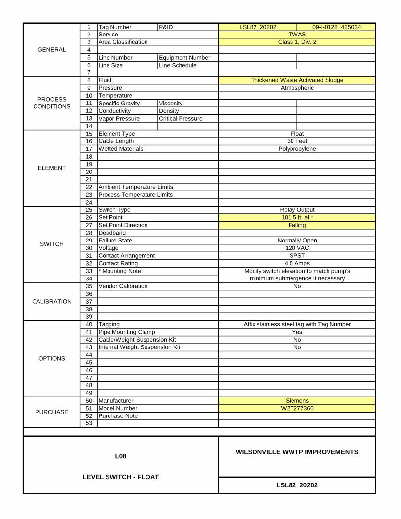
1 Tag Number P&ID LSL82_20202 09-I-0128_4250342345 Line Number Equipment Number6 Line Size Line Schedule789
1011 Specific Gravity Viscosity12 Conductivity Density13 Vapor Pressure Critical Pressure14151617181920212223242526272829303132333435363738394041424344454647484950515253
SWITCH
Set Point
Contact Arrangement
DeadbandFalling
Polypropylene
No
PROCESS CONDITIONS
CALIBRATION
ELEMENT
Wetted Materials
Vendor Calibration
OPTIONS
TaggingPipe Mounting Clamp
GENERAL
* Mounting Note
Switch Type
Process Temperature Limits
TWASClass 1, Div. 2
Thickened Waste Activated Sludge
PURCHASE
ServiceArea Classification
FluidAtmospheric
Element TypeCable Length
Float30 Feet
PressureTemperature
Modify switch elevation to match pump's
Manufacturer
Affix stainless steel tag with Tag NumberYesNoNo
minimum submergence if necessary
Voltage
Purchase Note
SiemensW2T277360
120 VAC
Contact Rating 4.5 Amps
LSL82_20202
WILSONVILLE WWTP IMPROVEMENTSL08
LEVEL SWITCH - FLOAT
Cable/Weight Suspension KitInternal Weight Suspension Kit
Model Number
SPST
Set Point Direction
Ambient Temperature Limits
Relay Output
Normally Open
101.5 ft. el.*
Failure State

L29LEVEL ELEMENT AND
TRANSMITTER, RADAR
PW/WBG/425034 JANUARY 2014 ©COPYRIGHT 2014 CH2M HILL
INSTRUMENT COMPONENTS40 91 00 SUPPLEMENT
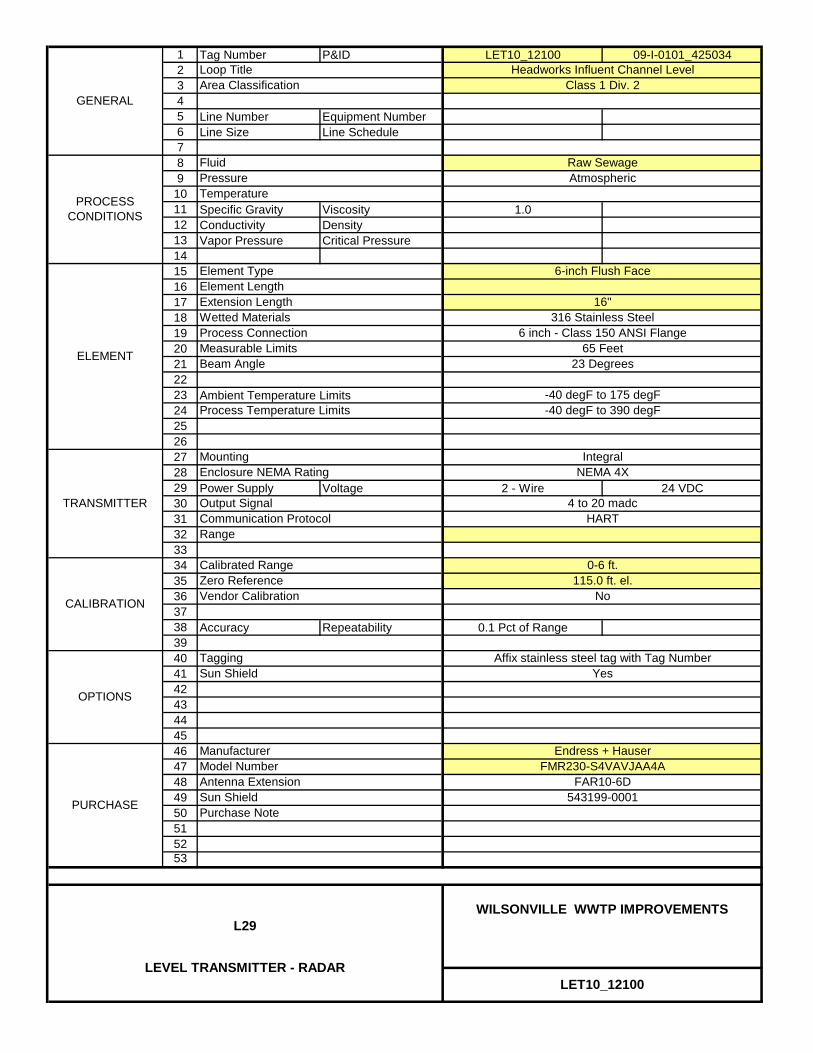
1 Tag Number P&ID LET10_12100 09-I-0101_4250342345 Line Number Equipment Number6 Line Size Line Schedule789
1011 Specific Gravity Viscosity 1.012 Conductivity Density13 Vapor Pressure Critical Pressure14151617181920212223 Ambient Temperature Limits242526272829 Power Supply Voltage 2 - Wire 24 VDC303132333435363738 Accuracy Repeatability 0.1 Pct of Range394041424344454647484950515253
PURCHASE 543199-0001
Model Number
LET10_12100
WILSONVILLE WWTP IMPROVEMENTSL29
LEVEL TRANSMITTER - RADAR
Endress + HauserFMR230-S4VAVJAA4A
FAR10-6D
Affix stainless steel tag with Tag NumberYes
Sun ShieldPurchase Note
Antenna Extension
Range
Manufacturer
115.0 ft. el.No
-40 degF to 390 degF
IntegralNEMA 4X
4 to 20 madcHART
Enclosure NEMA Rating
Output Signal
Element TypeElement Length
6-inch Flush Face
Communication Protocol
-40 degF to 175 degF
Mounting
Headworks Influent Channel LevelClass 1 Div. 2
Raw SewageAtmospheric
OPTIONS
TaggingSun Shield
GENERAL
Loop TitleArea Classification
FluidPressure
Measurable Limits
Extension LengthWetted MaterialsProcess Connection
Calibrated Range
Temperature
Process Temperature Limits
Zero ReferenceVendor Calibration
PROCESS CONDITIONS
TRANSMITTER
CALIBRATION
ELEMENT
16"316 Stainless Steel
Beam Angle
0-6 ft.
6 inch - Class 150 ANSI Flange65 Feet
23 Degrees

1 Tag Number P&ID LET10_12200 09-I-0101_4250342345 Line Number Equipment Number6 Line Size Line Schedule789
1011 Specific Gravity Viscosity 1.012 Conductivity Density13 Vapor Pressure Critical Pressure14151617181920212223 Ambient Temperature Limits242526272829 Power Supply Voltage 2 - Wire 24 VDC303132333435363738 Accuracy Repeatability 0.1 Pct of Range394041424344454647484950515253
PURCHASE 543199-0001
Model Number
LET10_12200
WILSONVILLE WWTP IMPROVEMENTSL29
LEVEL TRANSMITTER - RADAR
Endress + HauserFMR230-S4VAVJAA4A
FAR10-6D
Affix stainless steel tag with Tag NumberNo
Sun ShieldPurchase Note
Antenna Extension
Range
Manufacturer
115.0 ft. el.No
-40 degF to 390 degF
IntegralNEMA 4X
4 to 20 madcHART
Enclosure NEMA Rating
Output Signal
Element TypeElement Length
6-inch Flush Face
Communication Protocol
-40 degF to 175 degF
Mounting
Headworks Effluent Channel Level Class 1 Div. 2
Screened Raw SewageAtmospheric
OPTIONS
TaggingSun Shield
GENERAL
Loop TitleArea Classification
FluidPressure
Measurable Limits
Extension LengthWetted MaterialsProcess Connection
Calibrated Range
Temperature
Process Temperature Limits
Zero ReferenceVendor Calibration
PROCESS CONDITIONS
TRANSMITTER
CALIBRATION
ELEMENT
16"316 Stainless Steel
Beam Angle
0-4 ft.
6 inch - Class 150 ANSI Flange65 Feet
23 Degrees

1 Tag Number P&ID LET53_11000 09-I-0115_4250342345 Line Number Equipment Number6 Line Size Line Schedule789
1011 Specific Gravity Viscosity 1.012 Conductivity Density13 Vapor Pressure Critical Pressure14151617181920212223 Ambient Temperature Limits242526272829 Power Supply Voltage 2 - Wire 24 VDC303132333435363738 Accuracy Repeatability 0.1 Pct of Range394041424344454647484950515253
PURCHASE 543199-0001
Model Number
LET53_11000
WILSONVILLE WWTP IMPROVEMENTSL29
LEVEL TRANSMITTER - RADAR
Endress + HauserFMR230-A4VAVJAA4A
FAR10-6D
Affix stainless steel tag with Tag NumberNo
Sun ShieldPurchase Note
Antenna Extension
Range
Manufacturer
94.0 ft. el.No
-40 degF to 390 degF
IntegralNEMA 4X
4 to 20 madcHART
Enclosure NEMA Rating
Output Signal
Element TypeElement Length
6-inch Flush Face
Communication Protocol
-40 degF to 175 degF
Mounting
Secondary Effluent Wetwell LevelNone
Secondary EffluentAtmospheric
OPTIONS
TaggingSun Shield
GENERAL
Loop TitleArea Classification
FluidPressure
Measurable Limits
Extension LengthWetted MaterialsProcess Connection
Calibrated Range
Temperature
Process Temperature Limits
Zero ReferenceVendor Calibration
PROCESS CONDITIONS
TRANSMITTER
CALIBRATION
ELEMENT
16"316 Stainless Steel
Beam Angle
0-12 ft.
6 inch - Class 150 ANSI Flange65 Feet
23 Degrees

L41LEVEL ELEMENT AND
TRANSMITTER, SUBMERSIBLE
PW/WBG/425034 JANUARY 2014 ©COPYRIGHT 2014 CH2M HILL
INSTRUMENT COMPONENTS40 91 00 SUPPLEMENT

1 Tag Number P&ID LET40_12701 09-I-0105_4250342345 Line Number Equipment Number6 Line Size Line Schedule789
1011 Specific Gravity Viscosity 1.012 Conductivity Density13 Vapor Pressure Critical Pressure14151617181920212223242526272829 Power Supply Voltage 2 - Wire 24 VDC303132333435363738 Accuracy Repeatability 0.2 Pct of Range394041424344454647484950515253
1.66 inches
Measurable Limits
0-18 ft.
Terminal Box
9 psi/20 ft H2O
60 Feet
Mounting
Vendor Calibration
4 to 20 madcHARTCommunication Protocol
Calibrated Range
14 degF to 158 degF
PROCESS CONDITIONS
TRANSMITTER
CALIBRATION
ELEMENT
Pressure
Seal MaterialElement Outer Diameter
Temperature
Ambient Temperature Limits
Output Signal
Element TypeElement Material
OPTIONS
TaggingSun Shield
GENERAL
Loop TitleArea Classification
Fluid
Stabilization Basin 1 LevelClass 1, Div. 2
Return Activated SludgeAtmospheric
Affix stainless steel tag with Tag NumberNo
YesSuspension Clamp
YesNo
Manufacturer
No
Extension Cable Mounting Assembly
Purchase Note
Endress + HauserFMX21-FE221GGE21APRPSZ1
PURCHASE
Model Number
LET40_12701
WILSONVILLE WWTP IMPROVEMENTSL41
LEVEL TRANSMITTER - SUBMERSIBLE
Ceramic DiaphragmAISI 316L Stainless Steel
Viton
Extension Cable
Integral
Process Connection

1 Tag Number P&ID LET40_12702 09-I-0105_4250342345 Line Number Equipment Number6 Line Size Line Schedule789
1011 Specific Gravity Viscosity 1.012 Conductivity Density13 Vapor Pressure Critical Pressure14151617181920212223242526272829 Power Supply Voltage 2 - Wire 24 VDC303132333435363738 Accuracy Repeatability 0.2 Pct of Range394041424344454647484950515253
Ceramic DiaphragmAISI 316L Stainless Steel
Viton
Extension Cable
Integral
Process Connection
PURCHASE
Model Number
LET40_12702
WILSONVILLE WWTP IMPROVEMENTSL41
LEVEL TRANSMITTER - SUBMERSIBLE
Purchase Note
Endress + HauserFMX21-FE221GGE21APRPSZ1
Manufacturer
No
Extension Cable Mounting Assembly
Affix stainless steel tag with Tag NumberNo
YesSuspension Clamp
YesNo
Stabilization Basin 2 LevelClass 1, Div. 2
Return Activated SludgeAtmospheric
OPTIONS
TaggingSun Shield
GENERAL
Loop TitleArea Classification
Fluid
Temperature
Ambient Temperature Limits
Output Signal
Element TypeElement Material
14 degF to 158 degF
PROCESS CONDITIONS
TRANSMITTER
CALIBRATION
ELEMENT
Pressure
Seal MaterialElement Outer Diameter
Vendor Calibration
4 to 20 madcHARTCommunication Protocol
Calibrated Range
1.66 inches
Measurable Limits
0-18 ft.
Terminal Box
9 psi/20 ft H2O
60 Feet
Mounting

1 Tag Number P&ID LET50_20200 09-I-0114_4250342345 Line Number Equipment Number6 Line Size Line Schedule789
1011 Specific Gravity Viscosity 1.012 Conductivity Density13 Vapor Pressure Critical Pressure14151617181920212223242526272829 Power Supply Voltage 2 - Wire 24 VDC303132333435363738 Accuracy Repeatability 0.2 Pct of Range394041424344454647484950515253
1.66 inches
Measurable Limits
0-10 ft.
Terminal Box
9 psi/20 ft H2O
60 Feet
Mounting
Vendor Calibration
4 to 20 madcHARTCommunication Protocol
Calibrated Range
14 degF to 158 degF
PROCESS CONDITIONS
TRANSMITTER
CALIBRATION
ELEMENT
Pressure
Seal MaterialElement Outer Diameter
Temperature
Ambient Temperature Limits
Output Signal
Element TypeElement Material
OPTIONS
TaggingSun Shield
GENERAL
Loop TitleArea Classification
Fluid
Secondary Scum Pit LevelClass 1, Div. 2
Secondary ScumAtmospheric
Affix stainless steel tag with Tag NumberNo
YesSuspension Clamp
YesNo
Manufacturer
No
Extension Cable Mounting Assembly
Purchase Note
Endress + HauserFMX21-FE221GGE21APRPSZ1
PURCHASE
Model Number
LET50_20200
WILSONVILLE WWTP IMPROVEMENTSL41
LEVEL TRANSMITTER - SUBMERSIBLE
Ceramic DiaphragmAISI 316L Stainless Steel
Viton
Extension Cable
Integral
Process Connection
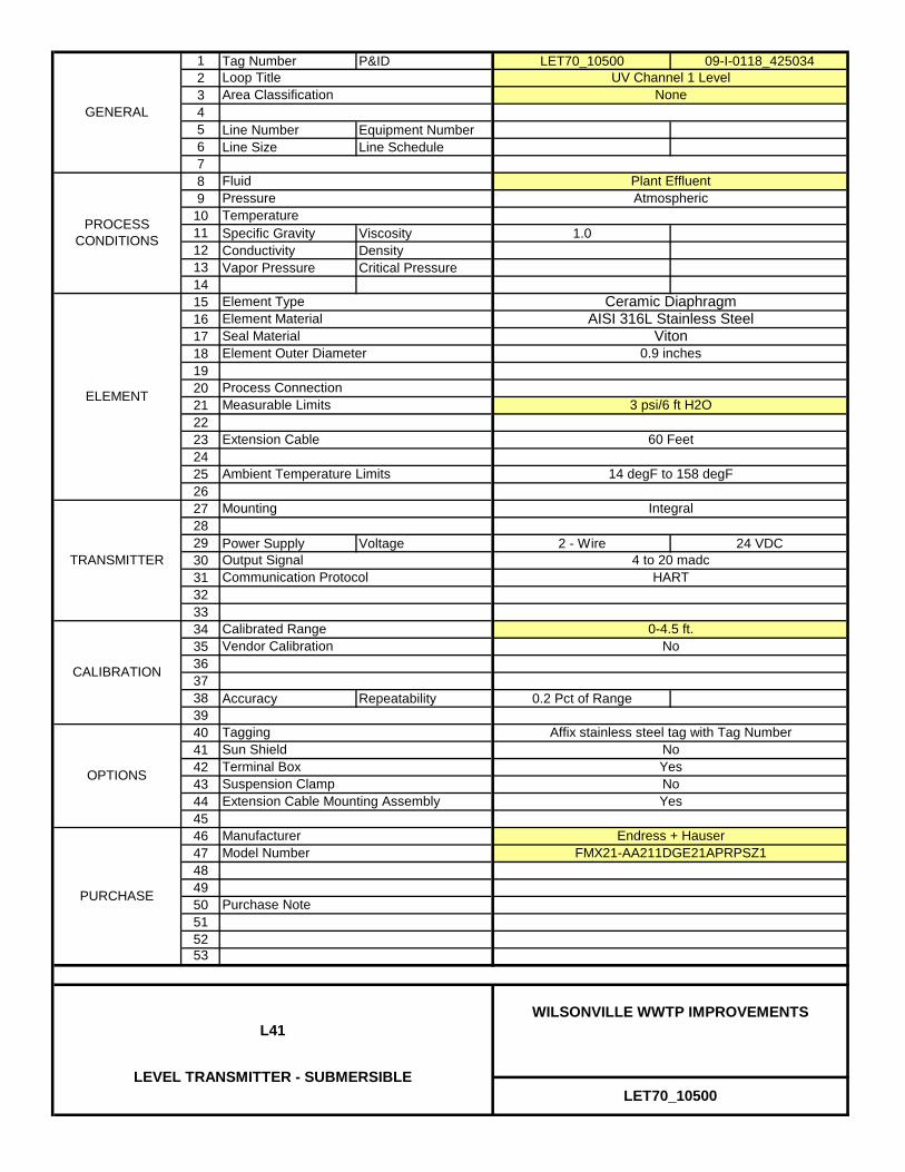
1 Tag Number P&ID LET70_10500 09-I-0118_4250342345 Line Number Equipment Number6 Line Size Line Schedule789
1011 Specific Gravity Viscosity 1.012 Conductivity Density13 Vapor Pressure Critical Pressure14151617181920212223242526272829 Power Supply Voltage 2 - Wire 24 VDC303132333435363738 Accuracy Repeatability 0.2 Pct of Range394041424344454647484950515253
Ceramic DiaphragmAISI 316L Stainless Steel
Viton
Extension Cable
Integral
Process Connection
PURCHASE
Model Number
LET70_10500
WILSONVILLE WWTP IMPROVEMENTSL41
LEVEL TRANSMITTER - SUBMERSIBLE
Purchase Note
Endress + HauserFMX21-AA211DGE21APRPSZ1
Manufacturer
No
Extension Cable Mounting Assembly
Affix stainless steel tag with Tag NumberNo
YesSuspension Clamp
YesNo
UV Channel 1 LevelNone
Plant EffluentAtmospheric
OPTIONS
TaggingSun Shield
GENERAL
Loop TitleArea Classification
Fluid
Temperature
Ambient Temperature Limits
Output Signal
Element TypeElement Material
14 degF to 158 degF
PROCESS CONDITIONS
TRANSMITTER
CALIBRATION
ELEMENT
Pressure
Seal MaterialElement Outer Diameter
Vendor Calibration
4 to 20 madcHARTCommunication Protocol
Calibrated Range
0.9 inches
Measurable Limits
0-4.5 ft.
Terminal Box
3 psi/6 ft H2O
60 Feet
Mounting

L50LEVEL SWITCH, TUNING FORK
PW/WBG/425034 JANUARY 2014 ©COPYRIGHT 2014 CH2M HILL
INSTRUMENT COMPONENTS40 91 00 SUPPLEMENT
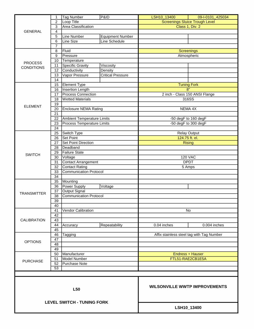
1 Tag Number P&ID LSH10_13400 09-I-0101_4250342345 Line Number Equipment Number6 Line Size Line Schedule789
1011 Specific Gravity Viscosity12 Conductivity Density13 Vapor Pressure Critical Pressure1415161718192021222324252627282930313233343536 Power Supply Voltage3738394041424344 Accuracy Repeatability 0.04 inches 0.004 inches454647484950515253
SWITCH
TRANSMITTER
Mounting
Output SignalCommunication Protocol
Set Point
Contact Arrangement
Deadband
2 inch - Class 150 ANSI Flange316SS
No
-50 degF to 160 degF-50 degF to 300 degF
PROCESS CONDITIONS
CALIBRATION
ELEMENT NEMA 4XEnclosure NEMA Rating
Process ConnectionWetted Materials
Vendor Calibration
OPTIONS
Tagging
GENERAL
Communication Protocol
Switch Type
Process Temperature Limits
Screenings Sluice Trough LevelClass 1, Div. 2
Screenings
PURCHASE
Loop TitleArea Classification
FluidAtmospheric
Element TypeInsertion Length
Tuning Fork8"
PressureTemperature
Ambient Temperature Limits
Purchase Note
Relay Output124.75 ft. el.
DPDT5 Amps
ManufacturerModel Number
Endress + HauserFTL51-RAE2CB1E5A
Affix stainless steel tag with Tag Number
LSH10_13400
WILSONVILLE WWTP IMPROVEMENTSL50
LEVEL SWITCH - TUNING FORK
Voltage 120 VAC
Contact Rating
Rising
Failure State
Set Point Direction

P03PRESSURE DIFFERENTIAL
TRANSMITTER
PW/WBG/425034 JANUARY 2014 ©COPYRIGHT 2014 CH2M HILL
INSTRUMENT COMPONENTS40 91 00 SUPPLEMENT
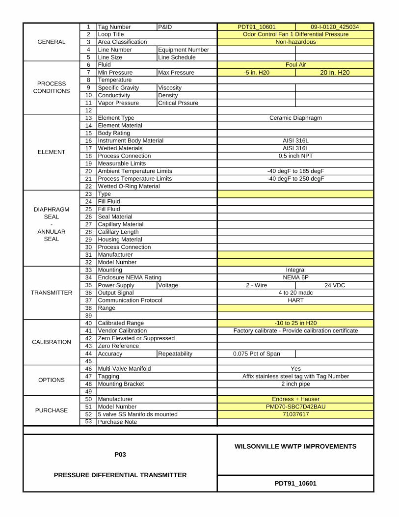
1 Tag Number P&ID PDT91_10601 09-I-0120_425034234 Line Number Equipment Number5 Line Size Line Schedule67 Min Pressure Max Pressure -5 in. H20 20 in. H2089 Specific Gravity Viscosity
10 Conductivity Density11 Vapor Pressure Critical Prssure121314151617181920212223242526272829303132333435 Power Supply Voltage 2 - Wire 24 VDC363738394041424344 Accuracy Repeatability 0.075 Pct of Span454647484950515253
AISI 316L
-40 degF to 185 degF-40 degF to 250 degF
AISI 316L0.5 inch NPT
71037617
PDT91_10601
WILSONVILLE WWTP IMPROVEMENTSP03
PRESSURE DIFFERENTIAL TRANSMITTER
5 valve SS Manifolds mounted
Communication Protocol
Vendor CalibrationZero Elevated or SuppressedZero Reference
Range
Purchase Note
Tagging
ManufacturerModel Number
Mounting Bracket 2 inch pipe
Factory calibrate - Provide calibration certificate
Endress + HauserPMD70-SBC7D42BAU
Affix stainless steel tag with Tag Number
IntegralNEMA 6P
4 to 20 madcHART
TRANSMITTER
Enclosure NEMA Rating
Output Signal
Mounting
Process Temperature Limits
TypeWetted O-Ring Material
Capillary MaterialCalillary Length
Calibrated Range
Odor Control Fan 1 Differential PressureNon-hazardous
Foul Air
PURCHASE
Loop TitleArea Classification
Fluid
Temperature
Process ConnectionELEMENT
CALIBRATION
Fill FluidSeal Material
Element TypeElement Material
Ceramic Diaphragm
Ambient Temperature LimitsMeasurable Limits
Body RatingInstrument Body MaterialWetted Materials
GENERAL
PROCESS CONDITIONS
-10 to 25 in H20
Yes
OPTIONS
Multi-Valve Manifold
DIAPHRAGM SEAL
- ANNULAR
SEAL
ManufacturerModel Number
Fill Fluid
Process ConnectionHousing Material

1 Tag Number P&ID PDT91_10602 09-I-0120_425034234 Line Number Equipment Number5 Line Size Line Schedule67 Min Pressure Max Pressure -5 in. H20 20 in. H2089 Specific Gravity Viscosity
10 Conductivity Density11 Vapor Pressure Critical Prssure121314151617181920212223242526272829303132333435 Power Supply Voltage 2 - Wire 24 VDC363738394041424344 Accuracy Repeatability 0.075 Pct of Span454647484950515253
Fill Fluid
Process ConnectionHousing Material
GENERAL
PROCESS CONDITIONS
-10 to 25 in H20
Yes
OPTIONS
Multi-Valve Manifold
DIAPHRAGM SEAL
- ANNULAR
SEAL
ManufacturerModel Number
Element TypeElement Material
Ceramic Diaphragm
Ambient Temperature LimitsMeasurable Limits
Body RatingInstrument Body MaterialWetted MaterialsProcess ConnectionELEMENT
CALIBRATION
Fill FluidSeal Material
Calibrated Range
Odor Control Fan 2 Differential PressureNon-hazardous
Foul Air
PURCHASE
Loop TitleArea Classification
Fluid
Temperature
TRANSMITTER
Enclosure NEMA Rating
Output Signal
Mounting
Process Temperature Limits
TypeWetted O-Ring Material
Capillary MaterialCalillary Length
PMD70-SBC7D42BAU
Affix stainless steel tag with Tag Number
IntegralNEMA 6P
4 to 20 madcHART
Mounting Bracket 2 inch pipe
Factory calibrate - Provide calibration certificate
Endress + Hauser
Communication Protocol
Vendor CalibrationZero Elevated or SuppressedZero Reference
Range
Purchase Note
Tagging
ManufacturerModel Number
71037617
PDT91_10602
WILSONVILLE WWTP IMPROVEMENTSP03
PRESSURE DIFFERENTIAL TRANSMITTER
5 valve SS Manifolds mounted
AISI 316L
-40 degF to 185 degF-40 degF to 250 degF
AISI 316L0.5 inch NPT

P04PRESSURE GAUGE
PW/WBG/425034 JANUARY 2014 ©COPYRIGHT 2014 CH2M HILL
INSTRUMENT COMPONENTS40 91 00 SUPPLEMENT

1 Tag Number P&ID PI10_10700 09-I-0101_4250342345 Line Number Equipment Number6 Line Size Line Schedule789 Min Pressure Max Pressure 0 psig 8.5 psig
1011 Specific Gravity Viscosity 1.012 Conductivity Density13 Vapor Pressure Critical Prssure14151617181920212223242526272829303132333435363738394041424344 Accuracy Repeatability 0.5 Pct of Range454647484950515253
PI10_10700
WILSONVILLE WWTP IMPROVEMENTSP04
PRESSURE GAUGE
PURCHASEModel NumberPurchase Note
Ashcroft45 1259SD 04L 15#
ORCS2I1100-04010-15 psig
Manufacturer
Vendor Calibration Factory calibrate - Provide calibration certificate
Affix stainless steel tag with Tag Number
Yes
Socket MaterialTube Materials Stainless Steel
Diaphragm / Sleeve Material
White
Buna-N316SSBody Material
Fluid
Temperature
Dial SizeRange
Vactor Sump Pump Discharge Pressure
Sump Pump Discharge
Ambient
Calibrated Range
OPTIONSTagging
GENERAL
Loop Title
Area Classification
PROCESS CONDITIONS
CALIBRATION
Window Material
INDICATOR
0.5 inch MNPT
GlycerinePhenolic
Movement Dampening
Acrylic
Dial ColorProcess ConnectionMounting
Bourdon TubeType0-15 psig
Lower Stem
4.5 inches
Case Material
Stainless Steel
Type
Blowout Protection
Process Connection
Capillary Material
Annular seal
Seal Tag NumberDIAPHRAGM
SEAL -
ANNULAR SEAL
ManufacturerModel Number
Case Back
OPW Engineered Systems
Fill Fluid
PE10_10700
Flushing ConnectionPropylene Glycol
Capillary Length

1 Tag Number P&ID PI10_30700 09-I-0104_4250342345 Line Number Equipment Number6 Line Size Line Schedule789 Min Pressure Max Pressure 0 psig 25 psig
1011 Specific Gravity Viscosity 1.012 Conductivity Density13 Vapor Pressure Critical Prssure14151617181920212223242526272829303132333435363738394041424344 Accuracy Repeatability 0.5 Pct of Range454647484950515253
OPW Engineered Systems
Fill Fluid
PE10_30700
Flushing ConnectionPropylene Glycol
Capillary Length
Annular seal
Seal Tag NumberDIAPHRAGM
SEAL -
ANNULAR SEAL
ManufacturerModel Number
Case Back
Stainless Steel
Type
Blowout Protection
Process Connection
Capillary Material
Acrylic
Dial ColorProcess ConnectionMounting
Bourdon TubeType0-60 psig
Lower Stem
4.5 inches
Case Material
PROCESS CONDITIONS
CALIBRATION
Window Material
INDICATOR
0.5 inch MNPT
GlycerinePhenolic
Movement Dampening
Calibrated Range
OPTIONSTagging
GENERAL
Loop Title
Area Classification
Grit Pump Discharge Pressure
Grit
Ambient
White
Buna-N316AABody Material
Fluid
Temperature
Dial SizeRange
Yes
Socket MaterialTube Materials Stainless Steel
Diaphragm / Sleeve Material
ORCS2I1100-04010-60 psig
Manufacturer
Vendor Calibration Factory calibrate - Provide calibration certificate
Affix stainless steel tag with Tag Number
Purchase Note
Ashcroft45 1259SD 04L 60#
PI10_30700
WILSONVILLE WWTP IMPROVEMENTSP04
PRESSURE GAUGE
PURCHASEModel Number

1 Tag Number P&ID PI50_03101 09-I-0113_4250342345 Line Number Equipment Number6 Line Size Line Schedule789 Min Pressure Max Pressure 0 psig 4.5 psig
1011 Specific Gravity Viscosity 1.012 Conductivity Density13 Vapor Pressure Critical Prssure14151617181920212223242526272829303132333435363738394041424344 Accuracy Repeatability 0.5 Pct of Range454647484950515253
Ashcroft
Fill Fluid
PE50_03101
Flushing ConnectionGlycerine
Capillary Length
Diaphragm seal
Seal Tag NumberDIAPHRAGM
SEAL -
ANNULAR SEAL
ManufacturerModel Number
Case Back
Stainless Steel
Type
Blowout Protection
Process Connection
Capillary Material
Acrylic
Dial ColorProcess ConnectionMounting
Bourdon TubeType0-15 psig
Lower Stem
4.5 inches
Case Material
PROCESS CONDITIONS
CALIBRATION
Window Material
INDICATOR
0.5 inch MNPT
GlycerinePhenolic
Movement Dampening
Calibrated Range
OPTIONSTagging
GENERAL
Loop Title
Area Classification
RAS Pump 1 Suction Pressure
Return Activated Sludge
Ambient
White
316SS316SSBody Material
Fluid
Temperature
Dial SizeRange
Yes
Socket MaterialTube Materials Stainless Steel
Diaphragm / Sleeve Material
1/2" FNPT
50-101SS-04T-CG0-15 psig
Manufacturer
Vendor Calibration Factory calibrate - Provide calibration certificate
Affix stainless steel tag with Tag Number
Purchase Note
Ashcroft45 1259SD 04L 15#
PI50_03101
WILSONVILLE WWTP IMPROVEMENTSP04
PRESSURE GAUGE
PURCHASEModel Number

1 Tag Number P&ID PI50_03102 09-I-0113_4250342345 Line Number Equipment Number6 Line Size Line Schedule789 Min Pressure Max Pressure 0 psig 4.5 psig
1011 Specific Gravity Viscosity 1.012 Conductivity Density13 Vapor Pressure Critical Prssure14151617181920212223242526272829303132333435363738394041424344 Accuracy Repeatability 0.5 Pct of Range454647484950515253
Ashcroft
Fill Fluid
PE50_03102
Flushing ConnectionGlycerine
Capillary Length
Diaphragm seal
Seal Tag NumberDIAPHRAGM
SEAL -
ANNULAR SEAL
ManufacturerModel Number
Case Back
Stainless Steel
Type
Blowout Protection
Process Connection
Capillary Material
Acrylic
Dial ColorProcess ConnectionMounting
Bourdon TubeType0-15 psig
Lower Stem
4.5 inches
Case Material
PROCESS CONDITIONS
CALIBRATION
Window Material
INDICATOR
0.5 inch MNPT
GlycerinePhenolic
Movement Dampening
Calibrated Range
OPTIONSTagging
GENERAL
Loop Title
Area Classification
RAS Pump 1 Suction Pressure
Return Activated Sludge
Ambient
White
316SS316SSBody Material
Fluid
Temperature
Dial SizeRange
Yes
Socket MaterialTube Materials Stainless Steel
Diaphragm / Sleeve Material
1/2" FNPT
50-101SS-04T-CG0-15 psig
Manufacturer
Vendor Calibration Factory calibrate - Provide calibration certificate
Affix stainless steel tag with Tag Number
Purchase Note
Ashcroft45 1259SD 04L 15#
PI50_03102
WILSONVILLE WWTP IMPROVEMENTSP04
PRESSURE GAUGE
PURCHASEModel Number

1 Tag Number P&ID PI50_03103 09-I-0113_4250342345 Line Number Equipment Number6 Line Size Line Schedule789 Min Pressure Max Pressure 0 psig 4.5 psig
1011 Specific Gravity Viscosity 1.012 Conductivity Density13 Vapor Pressure Critical Prssure14151617181920212223242526272829303132333435363738394041424344 Accuracy Repeatability 0.5 Pct of Range454647484950515253
Ashcroft
Fill Fluid
PE50_03103
Flushing ConnectionGlycerine
Capillary Length
Diaphragm seal
Seal Tag NumberDIAPHRAGM
SEAL -
ANNULAR SEAL
ManufacturerModel Number
Case Back
Stainless Steel
Type
Blowout Protection
Process Connection
Capillary Material
Acrylic
Dial ColorProcess ConnectionMounting
Bourdon TubeType0-15 psig
Lower Stem
4.5 inches
Case Material
PROCESS CONDITIONS
CALIBRATION
Window Material
INDICATOR
0.5 inch MNPT
GlycerinePhenolic
Movement Dampening
Calibrated Range
OPTIONSTagging
GENERAL
Loop Title
Area Classification
RAS Pump 3 Suction Pressure
Return Activated Sludge
Ambient
White
316SS316SSBody Material
Fluid
Temperature
Dial SizeRange
Yes
Socket MaterialTube Materials Stainless Steel
Diaphragm / Sleeve Material
1/2" FNPT
50-101SS-04T-CG0-15 psig
Manufacturer
Vendor Calibration Factory calibrate - Provide calibration certificate
Affix stainless steel tag with Tag Number
Purchase Note
Ashcroft45 1259SD 04L 15#
PI50_03103
WILSONVILLE WWTP IMPROVEMENTSP04
PRESSURE GAUGE
PURCHASEModel Number
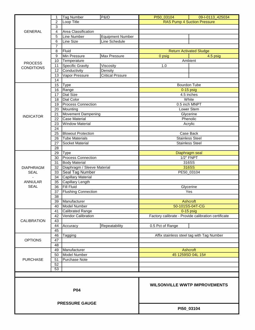
1 Tag Number P&ID PI50_03104 09-I-0113_4250342345 Line Number Equipment Number6 Line Size Line Schedule789 Min Pressure Max Pressure 0 psig 4.5 psig
1011 Specific Gravity Viscosity 1.012 Conductivity Density13 Vapor Pressure Critical Prssure14151617181920212223242526272829303132333435363738394041424344 Accuracy Repeatability 0.5 Pct of Range454647484950515253
Ashcroft
Fill Fluid
PE50_03104
Flushing ConnectionGlycerine
Capillary Length
Diaphragm seal
Seal Tag NumberDIAPHRAGM
SEAL -
ANNULAR SEAL
ManufacturerModel Number
Case Back
Stainless Steel
Type
Blowout Protection
Process Connection
Capillary Material
Acrylic
Dial ColorProcess ConnectionMounting
Bourdon TubeType0-15 psig
Lower Stem
4.5 inches
Case Material
PROCESS CONDITIONS
CALIBRATION
Window Material
INDICATOR
0.5 inch MNPT
GlycerinePhenolic
Movement Dampening
Calibrated Range
OPTIONSTagging
GENERAL
Loop Title
Area Classification
RAS Pump 4 Suction Pressure
Return Activated Sludge
Ambient
White
316SS316SSBody Material
Fluid
Temperature
Dial SizeRange
Yes
Socket MaterialTube Materials Stainless Steel
Diaphragm / Sleeve Material
1/2" FNPT
50-101SS-04T-CG0-15 psig
Manufacturer
Vendor Calibration Factory calibrate - Provide calibration certificate
Affix stainless steel tag with Tag Number
Purchase Note
Ashcroft45 1259SD 04L 15#
PI50_03104
WILSONVILLE WWTP IMPROVEMENTSP04
PRESSURE GAUGE
PURCHASEModel Number

1 Tag Number P&ID PI50_03201 09-I-0113_4250342345 Line Number Equipment Number6 Line Size Line Schedule789 Min Pressure Max Pressure 0 psig 8.5 psig
1011 Specific Gravity Viscosity 1.012 Conductivity Density13 Vapor Pressure Critical Prssure14151617181920212223242526272829303132333435363738394041424344 Accuracy Repeatability 0.5 Pct of Range454647484950515253
Ashcroft
Fill Fluid
PE50_03201
Flushing ConnectionGlycerine
Capillary Length
Diaphragm seal
Seal Tag NumberDIAPHRAGM
SEAL -
ANNULAR SEAL
ManufacturerModel Number
Case Back
Stainless Steel
Type
Blowout Protection
Process Connection
Capillary Material
Acrylic
Dial ColorProcess ConnectionMounting
Bourdon TubeType0-15 psig
Lower Stem
4.5 inches
Case Material
PROCESS CONDITIONS
CALIBRATION
Window Material
INDICATOR
0.5 inch MNPT
GlycerinePhenolic
Movement Dampening
Calibrated Range
OPTIONSTagging
GENERAL
Loop Title
Area Classification
RAS Pump 1 Discharge Pressure
Return Activated Sludge
Ambient
White
316SS316SSBody Material
Fluid
Temperature
Dial SizeRange
Yes
Socket MaterialTube Materials Stainless Steel
Diaphragm / Sleeve Material
1/2" FNPT
50-101SS-04T-CG0-15 psig
Manufacturer
Vendor Calibration Factory calibrate - Provide calibration certificate
Affix stainless steel tag with Tag Number
Purchase Note
Ashcroft45 1259SD 04L 15#
PI50_03201
WILSONVILLE WWTP IMPROVEMENTSP04
PRESSURE GAUGE
PURCHASEModel Number

1 Tag Number P&ID PI50_03202 09-I-0113_4250342345 Line Number Equipment Number6 Line Size Line Schedule789 Min Pressure Max Pressure 0 psig 8.5 psig
1011 Specific Gravity Viscosity 1.012 Conductivity Density13 Vapor Pressure Critical Prssure14151617181920212223242526272829303132333435363738394041424344 Accuracy Repeatability 0.5 Pct of Range454647484950515253
Ashcroft
Fill Fluid
PE50_03202
Flushing ConnectionGlycerine
Capillary Length
Diaphragm seal
Seal Tag NumberDIAPHRAGM
SEAL -
ANNULAR SEAL
ManufacturerModel Number
Case Back
Stainless Steel
Type
Blowout Protection
Process Connection
Capillary Material
Acrylic
Dial ColorProcess ConnectionMounting
Bourdon TubeType0-15 psig
Lower Stem
4.5 inches
Case Material
PROCESS CONDITIONS
CALIBRATION
Window Material
INDICATOR
0.5 inch MNPT
GlycerinePhenolic
Movement Dampening
Calibrated Range
OPTIONSTagging
GENERAL
Loop Title
Area Classification
RAS Pump 2 Discharge Pressure
Return Activated Sludge
Ambient
White
316SS316SSBody Material
Fluid
Temperature
Dial SizeRange
Yes
Socket MaterialTube Materials Stainless Steel
Diaphragm / Sleeve Material
1/2" FNPT
50-101SS-04T-CG0-15 psig
Manufacturer
Vendor Calibration Factory calibrate - Provide calibration certificate
Affix stainless steel tag with Tag Number
Purchase Note
Ashcroft45 1259SD 04L 15#
PI50_03202
WILSONVILLE WWTP IMPROVEMENTSP04
PRESSURE GAUGE
PURCHASEModel Number

1 Tag Number P&ID PI50_03203 09-I-0113_4250342345 Line Number Equipment Number6 Line Size Line Schedule789 Min Pressure Max Pressure 0 psig 8.5 psig
1011 Specific Gravity Viscosity 1.012 Conductivity Density13 Vapor Pressure Critical Prssure14151617181920212223242526272829303132333435363738394041424344 Accuracy Repeatability 0.5 Pct of Range454647484950515253
Ashcroft
Fill Fluid
PE50_03203
Flushing ConnectionGlycerine
Capillary Length
Diaphragm seal
Seal Tag NumberDIAPHRAGM
SEAL -
ANNULAR SEAL
ManufacturerModel Number
Case Back
Stainless Steel
Type
Blowout Protection
Process Connection
Capillary Material
Acrylic
Dial ColorProcess ConnectionMounting
Bourdon TubeType0-15 psig
Lower Stem
4.5 inches
Case Material
PROCESS CONDITIONS
CALIBRATION
Window Material
INDICATOR
0.5 inch MNPT
GlycerinePhenolic
Movement Dampening
Calibrated Range
OPTIONSTagging
GENERAL
Loop Title
Area Classification
RAS Pump 3 Discharge Pressure
Return Activated Sludge
Ambient
White
316SS316SSBody Material
Fluid
Temperature
Dial SizeRange
Yes
Socket MaterialTube Materials Stainless Steel
Diaphragm / Sleeve Material
1/2" FNPT
50-101SS-04T-CG0-15 psig
Manufacturer
Vendor Calibration Factory calibrate - Provide calibration certificate
Affix stainless steel tag with Tag Number
Purchase Note
Ashcroft45 1259SD 04L 15#
PI50_03203
WILSONVILLE WWTP IMPROVEMENTSP04
PRESSURE GAUGE
PURCHASEModel Number

1 Tag Number P&ID PI50_03204 09-I-0113_4250342345 Line Number Equipment Number6 Line Size Line Schedule789 Min Pressure Max Pressure 0 psig 8.5 psig
1011 Specific Gravity Viscosity 1.012 Conductivity Density13 Vapor Pressure Critical Prssure14151617181920212223242526272829303132333435363738394041424344 Accuracy Repeatability 0.5 Pct of Range454647484950515253
Ashcroft
Fill Fluid
PE50_03204
Flushing ConnectionGlycerine
Capillary Length
Diaphragm seal
Seal Tag NumberDIAPHRAGM
SEAL -
ANNULAR SEAL
ManufacturerModel Number
Case Back
Stainless Steel
Type
Blowout Protection
Process Connection
Capillary Material
Acrylic
Dial ColorProcess ConnectionMounting
Bourdon TubeType0-15 psig
Lower Stem
4.5 inches
Case Material
PROCESS CONDITIONS
CALIBRATION
Window Material
INDICATOR
0.5 inch MNPT
GlycerinePhenolic
Movement Dampening
Calibrated Range
OPTIONSTagging
GENERAL
Loop Title
Area Classification
RAS Pump 4 Discharge Pressure
Return Activated Sludge
Ambient
White
316SS316SSBody Material
Fluid
Temperature
Dial SizeRange
Yes
Socket MaterialTube Materials Stainless Steel
Diaphragm / Sleeve Material
1/2" FNPT
50-101SS-04T-CG0-15 psig
Manufacturer
Vendor Calibration Factory calibrate - Provide calibration certificate
Affix stainless steel tag with Tag Number
Purchase Note
Ashcroft45 1259SD 04L 15#
PI50_03204
WILSONVILLE WWTP IMPROVEMENTSP04
PRESSURE GAUGE
PURCHASEModel Number

1 Tag Number P&ID PI50_20300 09-I-0114_4250342345 Line Number Equipment Number6 Line Size Line Schedule789 Min Pressure Max Pressure 0 psig 40 psig
1011 Specific Gravity Viscosity 1.012 Conductivity Density13 Vapor Pressure Critical Prssure14151617181920212223242526272829303132333435363738394041424344 Accuracy Repeatability 0.5 Pct of Range454647484950515253
PI50_20300
WILSONVILLE WWTP IMPROVEMENTSP04
PRESSURE GAUGE
PURCHASEModel NumberPurchase Note
Ashcroft45 1259SD 04L 60#
50-101SS-04T-CG0-60 psig
Manufacturer
Vendor Calibration Factory calibrate - Provide calibration certificate
Affix stainless steel tag with Tag Number
Yes
Socket MaterialTube Materials Stainless Steel
Diaphragm / Sleeve Material
1/2" FNPT
White
316SS316SSBody Material
Fluid
Temperature
Dial SizeRange
Secondary Scum Pump Discharge Pressure
Secondary Scum
Ambient
Calibrated Range
OPTIONSTagging
GENERAL
Loop Title
Area Classification
PROCESS CONDITIONS
CALIBRATION
Window Material
INDICATOR
0.5 inch MNPT
GlycerinePhenolic
Movement Dampening
Acrylic
Dial ColorProcess ConnectionMounting
Bourdon TubeType0-60 psig
Lower Stem
4.5 inches
Case Material
Stainless Steel
Type
Blowout Protection
Process Connection
Capillary Material
Diaphragm seal
Seal Tag NumberDIAPHRAGM
SEAL -
ANNULAR SEAL
ManufacturerModel Number
Case Back
Ashcroft
Fill Fluid
PE50_20300
Flushing ConnectionGlycerine
Capillary Length

1 Tag Number P&ID PI53_10101 09-I-0115_4250342345 Line Number Equipment Number6 Line Size Line Schedule789 Min Pressure Max Pressure 0 psig 26 psig
1011 Specific Gravity Viscosity 1.012 Conductivity Density13 Vapor Pressure Critical Prssure14151617181920212223242526272829303132333435363738394041424344 Accuracy Repeatability 0.5 Pct of Range454647484950515253
Fill FluidFlushing Connection
Capillary Length
None
DIAPHRAGM SEAL
- ANNULAR
SEAL
ManufacturerModel Number
Case Back
Stainless Steel
Type
Blowout Protection
Process Connection
Capillary Material
Acrylic
Dial ColorProcess ConnectionMounting
Bourdon TubeType0-60 psig
Lower Stem
4.5 inches
Case Material
PROCESS CONDITIONS
CALIBRATION
Window Material
INDICATOR
0.5 inch MNPT
GlycerinePhenolic
Movement Dampening
Calibrated Range
OPTIONSTagging
GENERAL
Loop Title
Area Classification
Secondary Effluent Pump 1 Discharge Pressure
Secondary Effluent
Ambient
White
Body Material
Fluid
Temperature
Dial SizeRange
Socket MaterialTube Materials Stainless Steel
Diaphragm / Sleeve Material
0-60 psig
Manufacturer
Vendor Calibration Factory calibrate - Provide calibration certificate
Affix stainless steel tag with Tag Number
Purchase Note
Ashcroft45 1259SD 04L 60#
PI53_10101
WILSONVILLE WWTP IMPROVEMENTSP04
PRESSURE GAUGE
PURCHASEModel Number

1 Tag Number P&ID PI53_10102 09-I-0115_4250342345 Line Number Equipment Number6 Line Size Line Schedule789 Min Pressure Max Pressure 0 psig 26 psig
1011 Specific Gravity Viscosity 1.012 Conductivity Density13 Vapor Pressure Critical Prssure14151617181920212223242526272829303132333435363738394041424344 Accuracy Repeatability 0.5 Pct of Range454647484950515253
Fill FluidFlushing Connection
Capillary Length
None
DIAPHRAGM SEAL
- ANNULAR
SEAL
ManufacturerModel Number
Case Back
Stainless Steel
Type
Blowout Protection
Process Connection
Capillary Material
Acrylic
Dial ColorProcess ConnectionMounting
Bourdon TubeType0-60 psig
Lower Stem
4.5 inches
Case Material
PROCESS CONDITIONS
CALIBRATION
Window Material
INDICATOR
0.5 inch MNPT
GlycerinePhenolic
Movement Dampening
Calibrated Range
OPTIONSTagging
GENERAL
Loop Title
Area Classification
Secondary Effluent Pump 2 Discharge Pressure
Secondary Effluent
Ambient
White
Body Material
Fluid
Temperature
Dial SizeRange
Socket MaterialTube Materials Stainless Steel
Diaphragm / Sleeve Material
0-60 psig
Manufacturer
Vendor Calibration Factory calibrate - Provide calibration certificate
Affix stainless steel tag with Tag Number
Purchase Note
Ashcroft45 1259SD 04L 60#
PI53_10102
WILSONVILLE WWTP IMPROVEMENTSP04
PRESSURE GAUGE
PURCHASEModel Number

1 Tag Number P&ID PI53_10103 09-I-0115_4250342345 Line Number Equipment Number6 Line Size Line Schedule789 Min Pressure Max Pressure 0 psig 26 psig
1011 Specific Gravity Viscosity 1.012 Conductivity Density13 Vapor Pressure Critical Prssure14151617181920212223242526272829303132333435363738394041424344 Accuracy Repeatability 0.5 Pct of Range454647484950515253
Fill FluidFlushing Connection
Capillary Length
None
DIAPHRAGM SEAL
- ANNULAR
SEAL
ManufacturerModel Number
Case Back
Stainless Steel
Type
Blowout Protection
Process Connection
Capillary Material
Acrylic
Dial ColorProcess ConnectionMounting
Bourdon TubeType0-60 psig
Lower Stem
4.5 inches
Case Material
PROCESS CONDITIONS
CALIBRATION
Window Material
INDICATOR
0.5 inch MNPT
GlycerinePhenolic
Movement Dampening
Calibrated Range
OPTIONSTagging
GENERAL
Loop Title
Area Classification
Secondary Effluent Pump 3 Discharge Pressure
Secondary Effluent
Ambient
White
Body Material
Fluid
Temperature
Dial SizeRange
Socket MaterialTube Materials Stainless Steel
Diaphragm / Sleeve Material
0-60 psig
Manufacturer
Vendor Calibration Factory calibrate - Provide calibration certificate
Affix stainless steel tag with Tag Number
Purchase Note
Ashcroft45 1259SD 04L 60#
PI53_10103
WILSONVILLE WWTP IMPROVEMENTSP04
PRESSURE GAUGE
PURCHASEModel Number
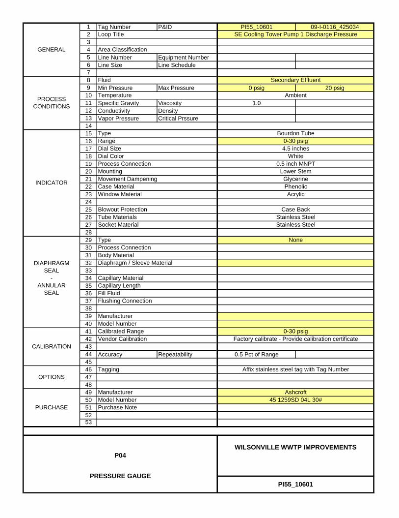
1 Tag Number P&ID PI55_10601 09-I-0116_4250342345 Line Number Equipment Number6 Line Size Line Schedule789 Min Pressure Max Pressure 0 psig 20 psig
1011 Specific Gravity Viscosity 1.012 Conductivity Density13 Vapor Pressure Critical Prssure14151617181920212223242526272829303132333435363738394041424344 Accuracy Repeatability 0.5 Pct of Range454647484950515253
PI55_10601
WILSONVILLE WWTP IMPROVEMENTSP04
PRESSURE GAUGE
PURCHASEModel NumberPurchase Note
Ashcroft45 1259SD 04L 30#
0-30 psig
Manufacturer
Vendor Calibration Factory calibrate - Provide calibration certificate
Affix stainless steel tag with Tag Number
Socket MaterialTube Materials Stainless Steel
Diaphragm / Sleeve Material
White
Body Material
Fluid
Temperature
Dial SizeRange
SE Cooling Tower Pump 1 Discharge Pressure
Secondary Effluent
Ambient
Calibrated Range
OPTIONSTagging
GENERAL
Loop Title
Area Classification
PROCESS CONDITIONS
CALIBRATION
Window Material
INDICATOR
0.5 inch MNPT
GlycerinePhenolic
Movement Dampening
Acrylic
Dial ColorProcess ConnectionMounting
Bourdon TubeType0-30 psig
Lower Stem
4.5 inches
Case Material
Stainless Steel
Type
Blowout Protection
Process Connection
Capillary Material
None
DIAPHRAGM SEAL
- ANNULAR
SEAL
ManufacturerModel Number
Case Back
Fill FluidFlushing Connection
Capillary Length

1 Tag Number P&ID PI55_10602 09-I-0116_4250342345 Line Number Equipment Number6 Line Size Line Schedule789 Min Pressure Max Pressure 0 psig 20 psig
1011 Specific Gravity Viscosity 1.012 Conductivity Density13 Vapor Pressure Critical Prssure14151617181920212223242526272829303132333435363738394041424344 Accuracy Repeatability 0.5 Pct of Range454647484950515253
PI55_10602
WILSONVILLE WWTP IMPROVEMENTSP04
PRESSURE GAUGE
PURCHASEModel NumberPurchase Note
Ashcroft45 1259SD 04L 30#
0-30 psig
Manufacturer
Vendor Calibration Factory calibrate - Provide calibration certificate
Affix stainless steel tag with Tag Number
Socket MaterialTube Materials Stainless Steel
Diaphragm / Sleeve Material
White
Body Material
Fluid
Temperature
Dial SizeRange
SE Cooling Tower Pump 2 Discharge Pressure
Secondary Effluent
Ambient
Calibrated Range
OPTIONSTagging
GENERAL
Loop Title
Area Classification
PROCESS CONDITIONS
CALIBRATION
Window Material
INDICATOR
0.5 inch MNPT
GlycerinePhenolic
Movement Dampening
Acrylic
Dial ColorProcess ConnectionMounting
Bourdon TubeType0-30 psig
Lower Stem
4.5 inches
Case Material
Stainless Steel
Type
Blowout Protection
Process Connection
Capillary Material
None
DIAPHRAGM SEAL
- ANNULAR
SEAL
ManufacturerModel Number
Case Back
Fill FluidFlushing Connection
Capillary Length
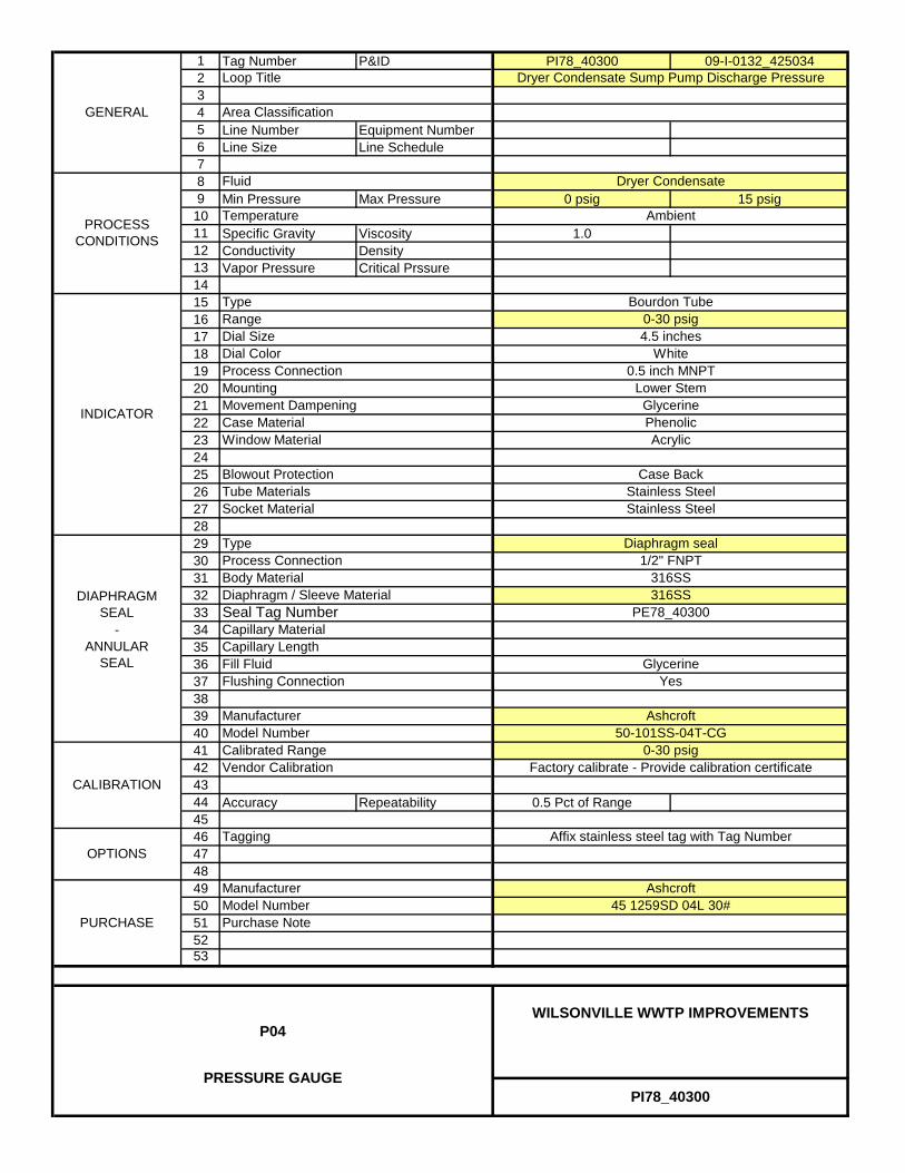
1 Tag Number P&ID PI78_40300 09-I-0132_4250342345 Line Number Equipment Number6 Line Size Line Schedule789 Min Pressure Max Pressure 0 psig 15 psig
1011 Specific Gravity Viscosity 1.012 Conductivity Density13 Vapor Pressure Critical Prssure14151617181920212223242526272829303132333435363738394041424344 Accuracy Repeatability 0.5 Pct of Range454647484950515253
Ashcroft
Fill Fluid
PE78_40300
Flushing ConnectionGlycerine
Capillary Length
Diaphragm seal
Seal Tag NumberDIAPHRAGM
SEAL -
ANNULAR SEAL
ManufacturerModel Number
Case Back
Stainless Steel
Type
Blowout Protection
Process Connection
Capillary Material
Acrylic
Dial ColorProcess ConnectionMounting
Bourdon TubeType0-30 psig
Lower Stem
4.5 inches
Case Material
PROCESS CONDITIONS
CALIBRATION
Window Material
INDICATOR
0.5 inch MNPT
GlycerinePhenolic
Movement Dampening
Calibrated Range
OPTIONSTagging
GENERAL
Loop Title
Area Classification
Dryer Condensate Sump Pump Discharge Pressure
Dryer Condensate
Ambient
White
316SS316SSBody Material
Fluid
Temperature
Dial SizeRange
Yes
Socket MaterialTube Materials Stainless Steel
Diaphragm / Sleeve Material
1/2" FNPT
50-101SS-04T-CG0-30 psig
Manufacturer
Vendor Calibration Factory calibrate - Provide calibration certificate
Affix stainless steel tag with Tag Number
Purchase Note
Ashcroft45 1259SD 04L 30#
PI78_40300
WILSONVILLE WWTP IMPROVEMENTSP04
PRESSURE GAUGE
PURCHASEModel Number

1 Tag Number P&ID PI82_10101 09-I-0125_4250342345 Line Number Equipment Number6 Line Size Line Schedule789 Min Pressure Max Pressure 0 psig 15 psig
1011 Specific Gravity Viscosity 1.012 Conductivity Density13 Vapor Pressure Critical Prssure14151617181920212223242526272829303132333435363738394041424344 Accuracy Repeatability 0.5 Pct of Range454647484950515253
OPW Engineered Systems
Fill Fluid
PE82_10101
Flushing ConnectionPropylene Glycol
Capillary Length
Annular seal
Seal Tag NumberDIAPHRAGM
SEAL -
ANNULAR SEAL
ManufacturerModel Number
Case Back
Stainless Steel
Type
Blowout Protection
Process Connection
Capillary Material
Acrylic
Dial ColorProcess ConnectionMounting
Bourdon TubeType0-30 psig
Lower Stem
4.5 inches
Case Material
PROCESS CONDITIONS
CALIBRATION
Window Material
INDICATOR
0.5 inch MNPT
GlycerinePhenolic
Movement Dampening
Calibrated Range
OPTIONSTagging
GENERAL
Loop Title
Area Classification
GBT Feed Pump 1 Discharge Pressure
Waste Activated Sludge
Ambient
White
Buna-N316SSBody Material
Fluid
Temperature
Dial SizeRange
Yes
Socket MaterialTube Materials Stainless Steel
Diaphragm / Sleeve Material
ORCS2I1100-06010-30 psig
Manufacturer
Vendor Calibration Factory calibrate - Provide calibration certificate
Affix stainless steel tag with Tag Number
Purchase Note
Ashcroft45 1259SD 04L 30#
PI82_10101
WILSONVILLE WWTP IMPROVEMENTSP04
PRESSURE GAUGE
PURCHASEModel Number
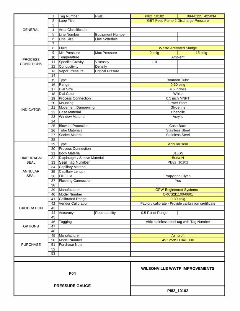
1 Tag Number P&ID PI82_10102 09-I-0125_4250342345 Line Number Equipment Number6 Line Size Line Schedule789 Min Pressure Max Pressure 0 psig 15 psig
1011 Specific Gravity Viscosity 1.012 Conductivity Density13 Vapor Pressure Critical Prssure14151617181920212223242526272829303132333435363738394041424344 Accuracy Repeatability 0.5 Pct of Range454647484950515253
OPW Engineered Systems
Fill Fluid
PE82_10102
Flushing ConnectionPropylene Glycol
Capillary Length
Annular seal
Seal Tag NumberDIAPHRAGM
SEAL -
ANNULAR SEAL
ManufacturerModel Number
Case Back
Stainless Steel
Type
Blowout Protection
Process Connection
Capillary Material
Acrylic
Dial ColorProcess ConnectionMounting
Bourdon TubeType0-30 psig
Lower Stem
4.5 inches
Case Material
PROCESS CONDITIONS
CALIBRATION
Window Material
INDICATOR
0.5 inch MNPT
GlycerinePhenolic
Movement Dampening
Calibrated Range
OPTIONSTagging
GENERAL
Loop Title
Area Classification
GBT Feed Pump 2 Discharge Pressure
Waste Activated Sludge
Ambient
White
Buna-N316SSBody Material
Fluid
Temperature
Dial SizeRange
Yes
Socket MaterialTube Materials Stainless Steel
Diaphragm / Sleeve Material
ORCS2I1100-06010-30 psig
Manufacturer
Vendor Calibration Factory calibrate - Provide calibration certificate
Affix stainless steel tag with Tag Number
Purchase Note
Ashcroft45 1259SD 04L 30#
PI82_10102
WILSONVILLE WWTP IMPROVEMENTSP04
PRESSURE GAUGE
PURCHASEModel Number

1 Tag Number P&ID PI82_20101 09-I-0128_4250342345 Line Number Equipment Number6 Line Size Line Schedule 3 inch789 Min Pressure Max Pressure 0 psig 40 psig1011 Specific Gravity Viscosity 1.012 Conductivity Density13 Vapor Pressure Critical Prssure14151617181920212223242526272829303132333435363738394041424344 Accuracy Repeatability 0.5 Pct of Range454647484950515253
PROCESS CONDITIONS
Fluid Thickened Waste Activated Sludge
Temperature Ambient
GENERAL
Loop Title Centrifuge Feed Pump 1 Discharge Pressure
Area Classification
0.5 inch MNPTMounting Lower StemMovement Dampening GlycerineCase Material PhenolicINDICATOR
Type Bourdon TubeRange 0-100 psigDial Size 4.5 inchesDial Color WhiteProcess Connection
Buna-NSeal Tag Number
Tube Materials Stainless SteelSocket Material Stainless Steel
Window Material Acrylic
Blowout Protection Case Back
Manufacturer OPW Engineered Systems Model Number RCS2I0000-0301
PE82_20101-
ANNULAR SEAL
Capillary MaterialCapillary LengthFill Fluid Propylene GlycolFlushing Connection Yes
DIAPHRAGM SEAL
Type Annular sealProcess ConnectionBody Material 316SSDiaphragm / Sleeve Material
OPTIONSTagging Affix stainless steel tag with Tag Number
CALIBRATION
Calibrated Range 0-100 psigVendor Calibration Factory calibrate - Provide calibration certificate
P04WILSONVILLE WWTP IMPROVEMENTS
PRESSURE GAUGEUpdated 7/10/2012
PI82_20101
PURCHASE
Manufacturer AshcroftModel Number 45 1259SL 04L XC4 100PSI/B724S XFS06C4Purchase Note
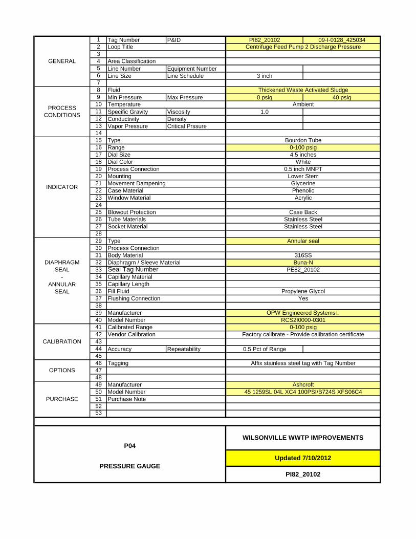
1 Tag Number P&ID PI82_20102 09-I-0128_4250342345 Line Number Equipment Number6 Line Size Line Schedule 3 inch789 Min Pressure Max Pressure 0 psig 40 psig1011 Specific Gravity Viscosity 1.012 Conductivity Density13 Vapor Pressure Critical Prssure14151617181920212223242526272829303132333435363738394041424344 Accuracy Repeatability 0.5 Pct of Range454647484950515253
PROCESS CONDITIONS
Fluid Thickened Waste Activated Sludge
Temperature Ambient
GENERAL
Loop Title Centrifuge Feed Pump 2 Discharge Pressure
Area Classification
0.5 inch MNPTMounting Lower StemMovement Dampening GlycerineCase Material PhenolicINDICATOR
Type Bourdon TubeRange 0-100 psigDial Size 4.5 inchesDial Color WhiteProcess Connection
Buna-NSeal Tag Number
Tube Materials Stainless SteelSocket Material Stainless Steel
Window Material Acrylic
Blowout Protection Case Back
Manufacturer OPW Engineered Systems Model Number RCS2I0000-0301
PE82_20102-
ANNULAR SEAL
Capillary MaterialCapillary LengthFill Fluid Propylene GlycolFlushing Connection Yes
DIAPHRAGM SEAL
Type Annular sealProcess ConnectionBody Material 316SSDiaphragm / Sleeve Material
OPTIONSTagging Affix stainless steel tag with Tag Number
CALIBRATION
Calibrated Range 0-100 psigVendor Calibration Factory calibrate - Provide calibration certificate
P04WILSONVILLE WWTP IMPROVEMENTS
PRESSURE GAUGEUpdated 7/10/2012
PI82_20102
PURCHASE
Manufacturer AshcroftModel Number 45 1259SL 04L XC4 100PSI/B724S XFS06C4Purchase Note

1 Tag Number P&ID PI91_12601 09-I-0120_4250342345 Line Number Equipment Number6 Line Size Line Schedule789 Min Pressure Max Pressure 0 psig 125 psig
1011 Specific Gravity Viscosity 1.012 Conductivity Density13 Vapor Pressure Critical Prssure14151617181920212223242526272829303132333435363738394041424344 Accuracy Repeatability 0.5 Pct of Range454647484950515253
PI91_12601
WILSONVILLE WWTP IMPROVEMENTSP04
PRESSURE GAUGE
PURCHASEModel NumberPurchase Note
Ashcroft45 1259SD 04L 160#
0-160 psig
Manufacturer
Vendor Calibration Factory calibrate - Provide calibration certificate
Affix stainless steel tag with Tag Number
Socket MaterialTube Materials Stainless Steel
Diaphragm / Sleeve Material
White
Body Material
Fluid
Temperature
Dial SizeRange
Odor Control W3 Supply Pressure
Plant Water
Ambient
Calibrated Range
OPTIONSTagging
GENERAL
Loop Title
Area Classification
PROCESS CONDITIONS
CALIBRATION
Window Material
INDICATOR
0.5 inch MNPT
GlycerinePhenolic
Movement Dampening
Acrylic
Dial ColorProcess ConnectionMounting
Bourdon TubeType0-160 psig
Lower Stem
4.5 inches
Case Material
Stainless Steel
Type
Blowout Protection
Process Connection
Capillary Material
None
DIAPHRAGM SEAL
- ANNULAR
SEAL
ManufacturerModel Number
Case Back
Fill FluidFlushing Connection
Capillary Length

1 Tag Number P&ID PI96_10101 09-I-0123_4250342345 Line Number Equipment Number6 Line Size Line Schedule789 Min Pressure Max Pressure 0 psig 100 psig
1011 Specific Gravity Viscosity 1.012 Conductivity Density13 Vapor Pressure Critical Prssure14151617181920212223242526272829303132333435363738394041424344 Accuracy Repeatability 0.5 Pct of Range454647484950515253
Fill FluidFlushing Connection
Capillary Length
None
DIAPHRAGM SEAL
- ANNULAR
SEAL
ManufacturerModel Number
Case Back
Stainless Steel
Type
Blowout Protection
Process Connection
Capillary Material
Acrylic
Dial ColorProcess ConnectionMounting
Bourdon TubeType0-160 psig
Lower Stem
4.5 inches
Case Material
PROCESS CONDITIONS
CALIBRATION
Window Material
INDICATOR
0.5 inch MNPT
GlycerinePhenolic
Movement Dampening
Calibrated Range
OPTIONSTagging
GENERAL
Loop Title
Area Classification
Plant Drain Pump 1 Discharge Pressure
Sump Pump Discharge
Ambient
White
Body Material
Fluid
Temperature
Dial SizeRange
Socket MaterialTube Materials Stainless Steel
Diaphragm / Sleeve Material
0-160 psig
Manufacturer
Vendor Calibration Factory calibrate - Provide calibration certificate
Affix stainless steel tag with Tag Number
Purchase Note
Ashcroft45 1259SD 04L 160#
PI96_10101
WILSONVILLE WWTP IMPROVEMENTSP04
PRESSURE GAUGE
PURCHASEModel Number

1 Tag Number P&ID PI96_10102 09-I-0123_4250342345 Line Number Equipment Number6 Line Size Line Schedule789 Min Pressure Max Pressure 0 psig 100 psig
1011 Specific Gravity Viscosity 1.012 Conductivity Density13 Vapor Pressure Critical Prssure14151617181920212223242526272829303132333435363738394041424344 Accuracy Repeatability 0.5 Pct of Range454647484950515253
Fill FluidFlushing Connection
Capillary Length
None
DIAPHRAGM SEAL
- ANNULAR
SEAL
ManufacturerModel Number
Case Back
Stainless Steel
Type
Blowout Protection
Process Connection
Capillary Material
Acrylic
Dial ColorProcess ConnectionMounting
Bourdon TubeType0-160 psig
Lower Stem
4.5 inches
Case Material
PROCESS CONDITIONS
CALIBRATION
Window Material
INDICATOR
0.5 inch MNPT
GlycerinePhenolic
Movement Dampening
Calibrated Range
OPTIONSTagging
GENERAL
Loop Title
Area Classification
Plant Drain Pump 2 Discharge Pressure
Sump Pump Discharge
Ambient
White
Body Material
Fluid
Temperature
Dial SizeRange
Socket MaterialTube Materials Stainless Steel
Diaphragm / Sleeve Material
0-160 psig
Manufacturer
Vendor Calibration Factory calibrate - Provide calibration certificate
Affix stainless steel tag with Tag Number
Purchase Note
Ashcroft45 1259SD 04L 160#
PI96_10102
WILSONVILLE WWTP IMPROVEMENTSP04
PRESSURE GAUGE
PURCHASEModel Number

P08PRESSURE SWITCH
PW/WBG/425034 JANUARY 2014 ©COPYRIGHT 2014 CH2M HILL
INSTRUMENT COMPONENTS40 91 00 SUPPLEMENT
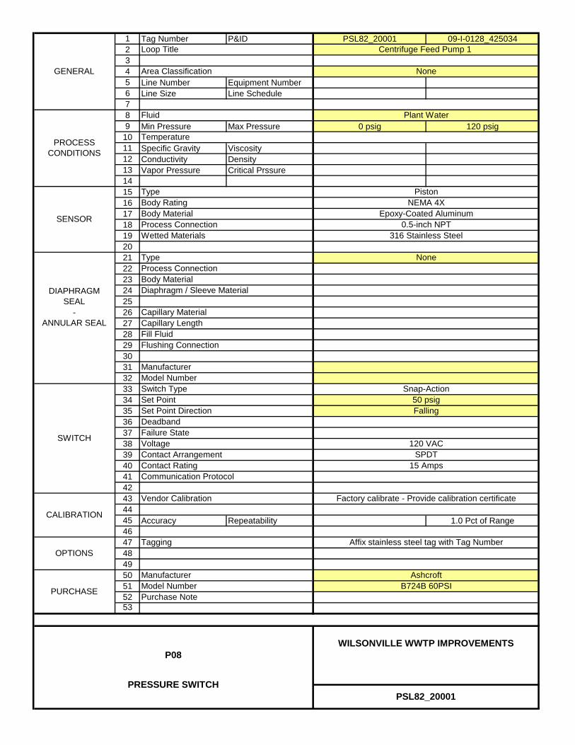
1 Tag Number P&ID PSL82_20001 09-I-0128_4250342345 Line Number Equipment Number6 Line Size Line Schedule789 Min Pressure Max Pressure 0 psig 120 psig
1011 Specific Gravity Viscosity12 Conductivity Density13 Vapor Pressure Critical Prssure1415161718192021222324252627282930313233343536373839404142434445 Accuracy Repeatability 1.0 Pct of Range4647484950515253
PSL82_20001
WILSONVILLE WWTP IMPROVEMENTSP08
PRESSURE SWITCH
B724B 60PSIPURCHASE
ManufacturerModel NumberPurchase Note
OPTIONS
Capillary Material
Body Material
Ashcroft
120 VAC
Process Connection
Diaphragm / Sleeve Material
Manufacturer
Centrifuge Feed Pump 1
None
Plant Water
None
Epoxy-Coated Aluminum0.5-inch NPT
TypeBody Rating
Wetted Materials
Loop Title
Area Classification
Fluid
Temperature
Body MaterialProcess Connection
Tagging
Type
Fill FluidFlushing Connection
Capillary Length
Model NumberSwitch Type
Contact Arrangement
GENERAL
PROCESS CONDITIONS
CALIBRATION
- ANNULAR SEAL
DIAPHRAGM SEAL
SENSOR
SWITCH
Affix stainless steel tag with Tag Number
Factory calibrate - Provide calibration certificate
PistonNEMA 4X
316 Stainless Steel
Communication Protocol
DeadbandFailure StateVoltage
Vendor Calibration
Set PointSet Point Direction
Snap-Action
SPDT15 Amps
50 psigFalling
Contact Rating

1 Tag Number P&ID PSL82_20002 09-I-0128_4250342345 Line Number Equipment Number6 Line Size Line Schedule789 Min Pressure Max Pressure 0 psig 120 psig
1011 Specific Gravity Viscosity12 Conductivity Density13 Vapor Pressure Critical Prssure1415161718192021222324252627282930313233343536373839404142434445 Accuracy Repeatability 1.0 Pct of Range4647484950515253
PSL82_20002
WILSONVILLE WWTP IMPROVEMENTSP08
PRESSURE SWITCH
B724B 60PSIPURCHASE
ManufacturerModel NumberPurchase Note
OPTIONS
Capillary Material
Body Material
Ashcroft
120 VAC
Process Connection
Diaphragm / Sleeve Material
Manufacturer
Centrifuge Feed Pump 2
None
Plant Water
None
Epoxy-Coated Aluminum0.5-inch NPT
TypeBody Rating
Wetted Materials
Loop Title
Area Classification
Fluid
Temperature
Body MaterialProcess Connection
Tagging
Type
Fill FluidFlushing Connection
Capillary Length
Model NumberSwitch Type
Contact Arrangement
GENERAL
PROCESS CONDITIONS
CALIBRATION
- ANNULAR SEAL
DIAPHRAGM SEAL
SENSOR
SWITCH
Affix stainless steel tag with Tag Number
Factory calibrate - Provide calibration certificate
PistonNEMA 4X
316 Stainless Steel
Communication Protocol
DeadbandFailure StateVoltage
Vendor Calibration
Set PointSet Point Direction
Snap-Action
SPDT15 Amps
50 psigFalling
Contact Rating
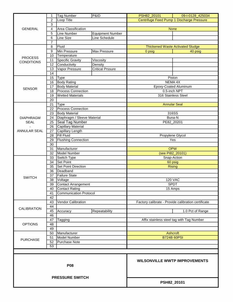
1 Tag Number P&ID PSH82_20101 09-I-0128_4250342345 Line Number Equipment Number6 Line Size Line Schedule789 Min Pressure Max Pressure 0 psig 40 psig
1011 Specific Gravity Viscosity12 Conductivity Density13 Vapor Pressure Critical Prssure1415161718192021222324252627282930313233343536373839404142434445 Accuracy Repeatability 1.0 Pct of Range4647484950515253
PSH82_20101
WILSONVILLE WWTP IMPROVEMENTSP08
PRESSURE SWITCH
B724B 60PSIPURCHASE
ManufacturerModel NumberPurchase Note
OPTIONS
Capillary Material
Body Material
OPW
Ashcroft
Yes
120 VAC
(see PI82_20101)
Process Connection
Diaphragm / Sleeve MaterialSeal Tag Number
Manufacturer
Buna-NPE82_20201
316SS
Propylene Glycol
Centrifuge Feed Pump 1 Discharge Pressure
None
Thickened Waste Activated Sludge
Annular Seal
Epoxy-Coated Aluminum0.5-inch NPT
TypeBody Rating
Wetted Materials
Loop Title
Area Classification
Fluid
Temperature
Body MaterialProcess Connection
Tagging
Type
Fill FluidFlushing Connection
Capillary Length
Model NumberSwitch Type
Contact Arrangement
GENERAL
PROCESS CONDITIONS
CALIBRATION
- ANNULAR SEAL
DIAPHRAGM SEAL
SENSOR
SWITCH
Affix stainless steel tag with Tag Number
Factory calibrate - Provide calibration certificate
PistonNEMA 4X
316 Stainless Steel
Communication Protocol
DeadbandFailure StateVoltage
Vendor Calibration
Set PointSet Point Direction
Snap-Action
SPDT15 Amps
60 psigRising
Contact Rating

1 Tag Number P&ID PSH82_20102 09-I-0128_4250342345 Line Number Equipment Number6 Line Size Line Schedule789 Min Pressure Max Pressure 0 psig 40 psig
1011 Specific Gravity Viscosity12 Conductivity Density13 Vapor Pressure Critical Prssure1415161718192021222324252627282930313233343536373839404142434445 Accuracy Repeatability 1.0 Pct of Range4647484950515253
PSH82_20102
WILSONVILLE WWTP IMPROVEMENTSP08
PRESSURE SWITCH
B724B 60PSIPURCHASE
ManufacturerModel NumberPurchase Note
OPTIONS
Capillary Material
Body Material
OPW
Ashcroft
Yes
120 VAC
(see PI82_20102)
Process Connection
Diaphragm / Sleeve MaterialSeal Tag Number
Manufacturer
Buna-NPE82_20201
316SS
Propylene Glycol
Centrifuge Feed Pump 2 Discharge Pressure
None
Thickened Waste Activated Sludge
Annular Seal
Epoxy-Coated Aluminum0.5-inch NPT
TypeBody Rating
Wetted Materials
Loop Title
Area Classification
Fluid
Temperature
Body MaterialProcess Connection
Tagging
Type
Fill FluidFlushing Connection
Capillary Length
Model NumberSwitch Type
Contact Arrangement
GENERAL
PROCESS CONDITIONS
CALIBRATION
- ANNULAR SEAL
DIAPHRAGM SEAL
SENSOR
SWITCH
Affix stainless steel tag with Tag Number
Factory calibrate - Provide calibration certificate
PistonNEMA 4X
316 Stainless Steel
Communication Protocol
DeadbandFailure StateVoltage
Vendor Calibration
Set PointSet Point Direction
Snap-Action
SPDT15 Amps
60 psigRising
Contact Rating

P09PRESSURE TRANSMITTER,
ELECTRONIC
PW/WBG/425034 JANUARY 2014 ©COPYRIGHT 2014 CH2M HILL
INSTRUMENT COMPONENTS40 91 00 SUPPLEMENT

1 Tag Number P&ID PIT40_50501 09-I-0110_425034234 Line Number Equipment Number5 Line Size Line Schedule67 Min Pressure Max Pressure 0 psig 15 psig89 Specific Gravity Viscosity
10 Conductivity Density11 Vapor Pressure Critical Pressure121314151617181920212223242526272829303132333435 Power Supply Voltage 2 - Wire 24 VDC363738394041424344 Accuracy Repeatability 0.075 Pct of Span454647484950515253
Process ConnectionNone
Capillary Length
Endress + HauserPMP71-AB31K61RHA
AISI 316L
-40 degF to 185 degF-40 degF to 250 degF
AISI 316L
Mounting Bracket
ManufacturerModel NumberMulti-Valve Manifold Model NumberPURCHASE
PIT40_50501
WILSONVILLE WWTP IMPROVEMENTSP09
PRESSURE TRANSMITTER
Purchase Note
Wall
Communication Protocol
Vendor CalibrationZero Elevated or SuppressedZero Reference
Range
Affix stainless steel tag with Tag Number
Factory calibrate - Provide calibration certificate
IntegralNEMA 6P
4 to 20 madcHART
Wetted MaterialsProcess ConnectionMeasurable Limits
Mounting
Process Temperature Limits
TypeWetted O-Ring Material
0.5 inch FNPT
Manufacturer
Aeration Blower Header PressureNone
Air Low Pressure
Metallic Welded Diaphragm
Loop TitleArea Classification
Fluid
Temperature
Body RatingInstrument Body Material
Ambient Temperature Limits
Element TypeElement Material
TRANSMITTER
ELEMENT
CALIBRATION
Body MaterialDIAPHRAGM
SEAL-
ANNULAR SEAL
Enclosure NEMA Rating
Calibrated Range
Fill FluidFlushing Connection
Diaphragm / Sleeve MaterialCapillary Material
Output Signal
Model Number
GENERAL
PROCESS CONDITIONS
0-18 psig
Yes (2-valve)
OPTIONS
Multi-Valve ManifoldTagging
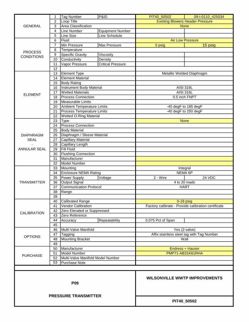
1 Tag Number P&ID PIT40_50502 09-I-0110_425034234 Line Number Equipment Number5 Line Size Line Schedule67 Min Pressure Max Pressure 0 psig 15 psig89 Specific Gravity Viscosity
10 Conductivity Density11 Vapor Pressure Critical Pressure121314151617181920212223242526272829303132333435 Power Supply Voltage 2 - Wire 24 VDC363738394041424344 Accuracy Repeatability 0.075 Pct of Span454647484950515253
GENERAL
PROCESS CONDITIONS
0-18 psig
Yes (2-valve)
OPTIONS
Multi-Valve ManifoldTagging
Calibrated Range
Fill FluidFlushing Connection
Diaphragm / Sleeve MaterialCapillary Material
Output Signal
Model Number
TRANSMITTER
ELEMENT
CALIBRATION
Body MaterialDIAPHRAGM
SEAL-
ANNULAR SEAL
Enclosure NEMA Rating
Loop TitleArea Classification
Fluid
Temperature
Body RatingInstrument Body Material
Ambient Temperature Limits
Element TypeElement Material
Existing Blowers Header PressureNone
Air Low Pressure
Metallic Welded Diaphragm
Wetted MaterialsProcess ConnectionMeasurable Limits
Mounting
Process Temperature Limits
TypeWetted O-Ring Material
0.5 inch FNPT
Manufacturer
Factory calibrate - Provide calibration certificate
IntegralNEMA 6P
4 to 20 madcHART
Purchase Note
Wall
Communication Protocol
Vendor CalibrationZero Elevated or SuppressedZero Reference
Range
Affix stainless steel tag with Tag Number
ManufacturerModel NumberMulti-Valve Manifold Model NumberPURCHASE
PIT40_50502
WILSONVILLE WWTP IMPROVEMENTSP09
PRESSURE TRANSMITTER
Endress + HauserPMP71-AB31K61RHA
AISI 316L
-40 degF to 185 degF-40 degF to 250 degF
AISI 316L
Mounting Bracket
Process ConnectionNone
Capillary Length
S12LOOP-POWERED INDICATOR
PW/WBG/425034 JANUARY 2014 ©COPYRIGHT 2014 CH2M HILL
INSTRUMENT COMPONENTS40 91 00 SUPPLEMENT
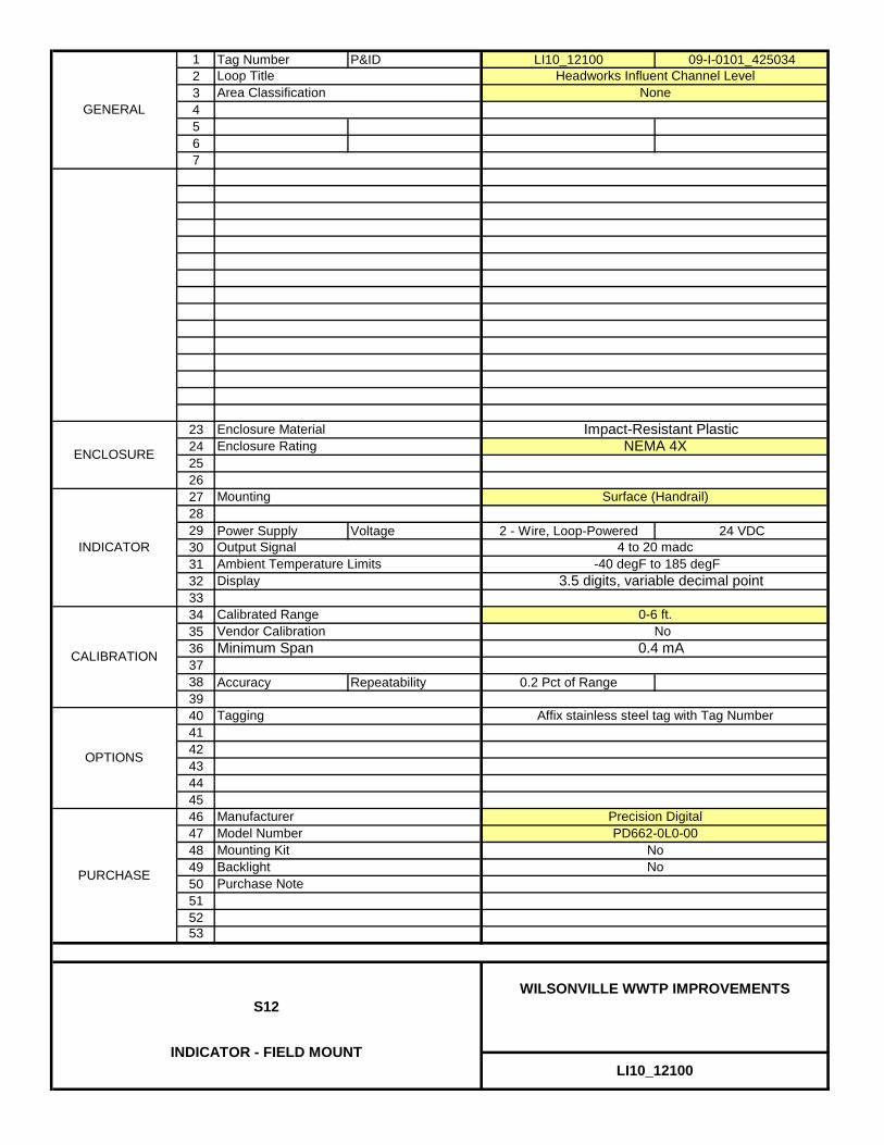
1 Tag Number P&ID LI10_12100 09-I-0101_425034234567
23242526272829 Power Supply Voltage 2 - Wire, Loop-Powered 24 VDC303132333435363738 Accuracy Repeatability 0.2 Pct of Range394041424344454647484950515253
0.4 mA
Enclosure Material
3.5 digits, variable decimal point
NEMA 4X
Surface (Handrail)
4 to 20 madc
PURCHASE No
Model Number
LI10_12100
WILSONVILLE WWTP IMPROVEMENTSS12
INDICATOR - FIELD MOUNT
Precision DigitalPD662-0L0-00
No
Affix stainless steel tag with Tag Number
BacklightPurchase Note
Mounting Kit
Display
Manufacturer
No
Output SignalAmbient Temperature Limits
Headworks Influent Channel LevelNone
GENERAL
Loop TitleArea Classification
Mounting
Minimum Span
Calibrated Range
Enclosure Rating
Vendor Calibration
INDICATOR
CALIBRATION
OPTIONS
Tagging
0-6 ft.
Impact-Resistant Plastic
-40 degF to 185 degF
ENCLOSURE

1 Tag Number P&ID LI10_12200 09-I-0101_425034234567
23242526272829 Power Supply Voltage 2 - Wire, Loop-Powered 24 VDC303132333435363738 Accuracy Repeatability 0.2 Pct of Range394041424344454647484950515253
0.4 mA
Enclosure Material
3.5 digits, variable decimal point
NEMA 4X
Surface (Handrail)
4 to 20 madc
PURCHASE No
Model Number
LI10_12200
WILSONVILLE WWTP IMPROVEMENTSS12
INDICATOR - FIELD MOUNT
Precision DigitalPD662-0L0-00
No
Affix stainless steel tag with Tag Number
BacklightPurchase Note
Mounting Kit
Display
Manufacturer
No
Output SignalAmbient Temperature Limits
Headworks Effluent Channel Level None
GENERAL
Loop TitleArea Classification
Mounting
Minimum Span
Calibrated Range
Enclosure Rating
Vendor Calibration
INDICATOR
CALIBRATION
OPTIONS
Tagging
0-4 ft.
Impact-Resistant Plastic
-40 degF to 185 degF
ENCLOSURE

1 Tag Number P&ID LI40_12701 09-I-0105_425034234567
23242526272829 Power Supply Voltage 2 - Wire, Loop-Powered 24 VDC303132333435363738 Accuracy Repeatability 0.2 Pct of Range394041424344454647484950515253
ENCLOSURE
0-18 ft.
Impact-Resistant Plastic
-40 degF to 185 degF
Vendor Calibration
INDICATOR
CALIBRATION
OPTIONS
Tagging
Calibrated Range
Enclosure Rating
GENERAL
Loop TitleArea Classification
Mounting
Minimum Span
Stabilization Basin 1 LevelNone
Output SignalAmbient Temperature Limits
Mounting Kit
Display
Manufacturer
No
BacklightPurchase Note
Precision DigitalPD662-0L0-00
No
Affix stainless steel tag with Tag Number
PURCHASE No
Model Number
LI40_12701
WILSONVILLE WWTP IMPROVEMENTSS12
INDICATOR - FIELD MOUNT
0.4 mA
Enclosure Material
3.5 digits, variable decimal point
NEMA 4X
Surface (Stanchion)
4 to 20 madc

1 Tag Number P&ID LI40_12702 09-I-0105_425034234567
23242526272829 Power Supply Voltage 2 - Wire, Loop-Powered 24 VDC303132333435363738 Accuracy Repeatability 0.2 Pct of Range394041424344454647484950515253
0.4 mA
Enclosure Material
3.5 digits, variable decimal point
NEMA 4X
Surface (Stanchion)
4 to 20 madc
PURCHASE No
Model Number
LI40_12702
WILSONVILLE WWTP IMPROVEMENTSS12
INDICATOR - FIELD MOUNT
Precision DigitalPD662-0L0-00
No
Affix stainless steel tag with Tag Number
BacklightPurchase Note
Mounting Kit
Display
Manufacturer
No
Output SignalAmbient Temperature Limits
Stabilization Basin 2 LevelNone
GENERAL
Loop TitleArea Classification
Mounting
Minimum Span
Calibrated Range
Enclosure Rating
Vendor Calibration
INDICATOR
CALIBRATION
OPTIONS
Tagging
0-18 ft.
Impact-Resistant Plastic
-40 degF to 185 degF
ENCLOSURE

1 Tag Number P&ID LI50_20200 09-I-0114_425034234567
23242526272829 Power Supply Voltage 2 - Wire, Loop-Powered 24 VDC303132333435363738 Accuracy Repeatability 0.2 Pct of Range394041424344454647484950515253
ENCLOSURE
0-10 ft.
Impact-Resistant Plastic
-40 degF to 185 degF
Vendor Calibration
INDICATOR
CALIBRATION
OPTIONS
Tagging
Calibrated Range
Enclosure Rating
GENERAL
Loop TitleArea Classification
Mounting
Minimum Span
Secondary Scum Pit LevelClass 1 Div. 2
Output SignalAmbient Temperature Limits
Mounting Kit
Display
Manufacturer
No
BacklightPurchase Note
Precision DigitalPD663-0L0-00
No
Affix stainless steel tag with Tag Number
PURCHASE No
Model Number
LI50_20200
WILSONVILLE WWTP IMPROVEMENTSS12
INDICATOR - FIELD MOUNT
0.4 mA
Enclosure Material
3.5 digits, variable decimal point
Class 1 Div. 2
Surface (Short Wall)
4 to 20 madc

1 Tag Number P&ID LI70_10500 09-I-0118_425034234567
23242526272829 Power Supply Voltage 2 - Wire, Loop-Powered 24 VDC303132333435363738 Accuracy Repeatability 0.2 Pct of Range394041424344454647484950515253
0.4 mA
Enclosure Material
3.5 digits, variable decimal point
NEMA 4X
Surface (Stanchion)
4 to 20 madc
PURCHASE No
Model Number
LI70_10500
WILSONVILLE WWTP IMPROVEMENTSS12
INDICATOR - FIELD MOUNT
Precision DigitalPD662-0L0-00
No
Affix stainless steel tag with Tag Number
BacklightPurchase Note
Mounting Kit
Display
Manufacturer
No
Output SignalAmbient Temperature Limits
UV Channel 1 LevelNone
GENERAL
Loop TitleArea Classification
Mounting
Minimum Span
Calibrated Range
Enclosure Rating
Vendor Calibration
INDICATOR
CALIBRATION
OPTIONS
Tagging
0-4.5 ft.
Impact-Resistant Plastic
-40 degF to 185 degF
ENCLOSURE

T03TEMPERATURE ELEMENT AND
TRANSMITTER, RESISTANCE
PW/WBG/425034 JANUARY 2014 ©COPYRIGHT 2014 CH2M HILL
INSTRUMENT COMPONENTS40 91 00 SUPPLEMENT

1 Tag Number P&ID TIT70_21700 09-I-0118_425034234 Line Number Equipment Number5 Line Size Line Schedule 2.5"6789 Min Temperature Max Temperature 32 deg. F 80 deg. F
10 Specific Gravity Viscosity11 Conductivity Density12 Vapor Pressure Critical Prssure1314151617181920 Spring Loaded Yes2122 Manufacturer Model Number232425262728293031323334 Power Supply Voltage 2 - Wire 24 VDC353637383940 Ambient Temperature Limits414243444546 Accuracy Repeatability 0.4 degF47484950515253
Model Number
IntegralNEMA 4X
4 to 20 madc
2.5"
1 inch NPT
None
-40 degF to 185 degF
TEMPERATURE TRANSMITTER - RTD
Factory calibrate - Provide calibration certificate
Endress + HauserManufacturer
Purchase Note
Affix stainless steel tag with Tag Number
HART
TIT70_21700
WILSONVILLE WWTP IMPROVEMENTS
30-100 degF
PURCHASE
Display
SteppedMaterialBore Diameter
Digital
TRANSMITTER Range
Mounting
Process Connection
T03
Enclosure NEMA Rating
Output Signal
TH13-1A32A2AIM1BK
Head Type
316 Stainless SteelConstruction Type
Vendor Calibration
Total Length
Insertion Length - "U"
Process Temperature Limits
FluidNominal Pressure
Failsafe Mode
Element TypeElement MaterialElement Length
THERMOWELL
CALIBRATION
Process Connection
Communication Protocol
Insulation LengthLag Extension Length - "T"
GENERAL
PROCESS CONDITIONS
5 psig
Plant Effluent Temperature
Element Tag
ELEMENT
Single - Three Wire
Loop TitleArea Classification
Platinum - 100 ohms
TE70_21700
None
Plant Effluent Sample
OPTIONS Tagging
Calibrated Range

T09THERMOMETER, ADJUSTABLE ANGLE
PW/WBG/425034 JANUARY 2014 ©COPYRIGHT 2014 CH2M HILL
INSTRUMENT COMPONENTS40 91 00 SUPPLEMENT

1 Tag Number P&ID TI55_10101 09-I-0116_425034234 Line Number Equipment Number5 Line Size Line Schedule 10"6789 Min Temperature Max Temperature 32 deg F 80 deg F
10 Specific Gravity Viscosity11 Conductivity Density12 Vapor Pressure Critical Prssure13141516171819202122 Manufacturer Model Number232425262728293031323334 Power Supply Voltage353637383940 Ambient Temperature Limits414243444546 Accuracy Repeatability +/- 1.0% of span47484950515253
7.5"
1 inch NPT
None
THERMOMETER, ADJUSTABLE ANGLE
Factory calibrate - Provide calibration certificate
AshcroftManufacturer
Purchase Note
Affix stainless steel tag with Tag Number
TI55_10101
WILSONVILLE WWTP IMPROVEMENTST09
OPTIONS
Enclosure NEMA Rating
30 - 100 deg F
Tagging
CALIBRATION
MaterialBore Diameter
TRANSMITTER
N/A
Output Signal
600B-01-AG-XNNPURCHASE
Display
Model Number
Vendor Calibration
Process Connection
Total Length
Insertion Length - "U"
Process Temperature Limits
Range
Mounting
Stepped
Failsafe Mode
Element Length
Range
4.5 inchesDial Size
316 stainless steelConstruction Type
match thermowell
Loop TitleArea Classification
THERMOWELL
FluidNominal Pressure
Element TypeElement Material
Process Connection
Insulation Length
GENERAL
PROCESS CONDITIONS
10 psig
SE Cooling Tower 1 Influent Temperature
316 SS
Element Tag
ELEMENT
Bimetal
Unclassified
Secondary Effluent
Calibrated Range
Communication Protocol
Lag Extension Length - "T"
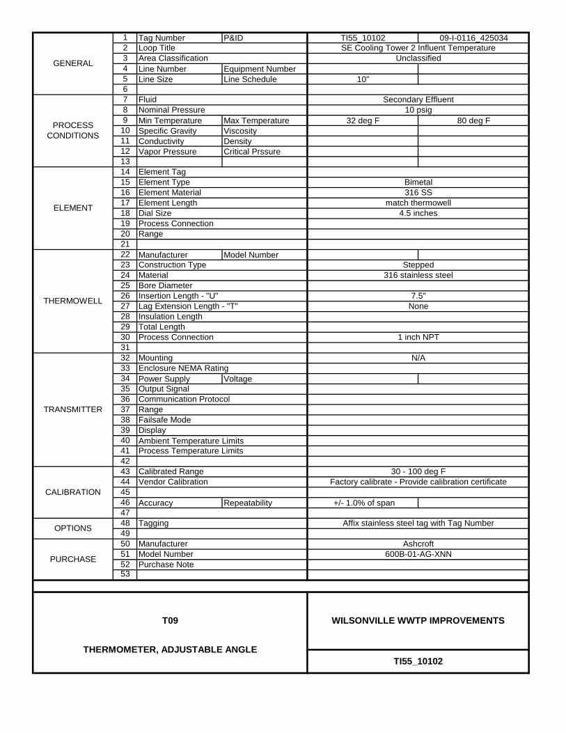
1 Tag Number P&ID TI55_10102 09-I-0116_425034234 Line Number Equipment Number5 Line Size Line Schedule 10"6789 Min Temperature Max Temperature 32 deg F 80 deg F
10 Specific Gravity Viscosity11 Conductivity Density12 Vapor Pressure Critical Prssure13141516171819202122 Manufacturer Model Number232425262728293031323334 Power Supply Voltage353637383940 Ambient Temperature Limits414243444546 Accuracy Repeatability +/- 1.0% of span47484950515253
Unclassified
Secondary Effluent
Calibrated Range
Communication Protocol
Lag Extension Length - "T"
GENERAL
PROCESS CONDITIONS
10 psig
SE Cooling Tower 2 Influent Temperature
316 SS
Element Tag
ELEMENT
Bimetal
Loop TitleArea Classification
THERMOWELL
FluidNominal Pressure
Element TypeElement Material
Process Connection
Insulation Length
Element Length
Range
4.5 inchesDial Size
316 stainless steelConstruction Type
match thermowell
Process Connection
Total Length
Insertion Length - "U"
Process Temperature Limits
Range
Mounting
Stepped
Output Signal
600B-01-AG-XNNPURCHASE
Display
Model Number
Vendor CalibrationCALIBRATION
MaterialBore Diameter
TRANSMITTER
N/AEnclosure NEMA Rating
30 - 100 deg F
Tagging
Failsafe Mode
Manufacturer
Purchase Note
Affix stainless steel tag with Tag Number
TI55_10102
WILSONVILLE WWTP IMPROVEMENTST09
OPTIONS
7.5"
1 inch NPT
None
THERMOMETER, ADJUSTABLE ANGLE
Factory calibrate - Provide calibration certificate
Ashcroft

1 Tag Number P&ID TI55_10201 09-I-0116_425034234 Line Number Equipment Number5 Line Size Line Schedule 10"6789 Min Temperature Max Temperature 32 deg F 80 deg F
10 Specific Gravity Viscosity11 Conductivity Density12 Vapor Pressure Critical Prssure13141516171819202122 Manufacturer Model Number232425262728293031323334 Power Supply Voltage353637383940 Ambient Temperature Limits414243444546 Accuracy Repeatability +/- 1.0% of span47484950515253
Unclassified
Secondary Effluent
Calibrated Range
Communication Protocol
Lag Extension Length - "T"
GENERAL
PROCESS CONDITIONS
10 psig
SE Cooling Tower 1 Effluent Temperature
316 SS
Element Tag
ELEMENT
Bimetal
Loop TitleArea Classification
THERMOWELL
FluidNominal Pressure
Element TypeElement Material
Process Connection
Insulation Length
Element Length
Range
4.5 inchesDial Size
316 stainless steelConstruction Type
match thermowell
Process Connection
Material
Total Length
Insertion Length - "U"
Process Temperature Limits
Range
Mounting
Stepped
Output Signal
600B-01-AG-XNNPURCHASE
Display
Model Number
Vendor CalibrationCALIBRATION
Bore Diameter
TRANSMITTER
N/AEnclosure NEMA Rating
Affix stainless steel tag with Tag Number
30 - 100 deg F
Tagging
7.5"
1 inch NPT
None
THERMOMETER, ADJUSTABLE ANGLE
Failsafe Mode
Manufacturer
Purchase Note
Factory calibrate - Provide calibration certificate
Ashcroft
TI55_10201
WILSONVILLE WWTP IMPROVEMENTST09
OPTIONS

1 Tag Number P&ID TI55_10202 09-I-0116_425034234 Line Number Equipment Number5 Line Size Line Schedule 10"6789 Min Temperature Max Temperature 32 deg F 80 deg F
10 Specific Gravity Viscosity11 Conductivity Density12 Vapor Pressure Critical Prssure13141516171819202122 Manufacturer Model Number232425262728293031323334 Power Supply Voltage353637383940 Ambient Temperature Limits414243444546 Accuracy Repeatability +/- 1.0% of span47484950515253
Factory calibrate - Provide calibration certificate
Ashcroft
TI55_10202
WILSONVILLE WWTP IMPROVEMENTST09
OPTIONS
7.5"
1 inch NPT
None
THERMOMETER, ADJUSTABLE ANGLE
Failsafe Mode
Manufacturer
Purchase Note
Affix stainless steel tag with Tag Number
30 - 100 deg F
Tagging
Bore Diameter
TRANSMITTER
N/AEnclosure NEMA Rating
Output Signal
600B-01-AG-XNNPURCHASE
Display
Model Number
Vendor CalibrationCALIBRATION
Total Length
Insertion Length - "U"
Process Temperature Limits
Range
Mounting
Stepped
Element Length
Range
4.5 inchesDial Size
316 stainless steelConstruction Type
match thermowell
Process Connection
Material
Loop TitleArea Classification
THERMOWELL
FluidNominal Pressure
Element TypeElement Material
Process Connection
Insulation Length
GENERAL
PROCESS CONDITIONS
10 psig
SE Cooling Tower 2 Effluent Temperature
316 SS
Element Tag
ELEMENT
Bimetal
Unclassified
Secondary Effluent
Calibrated Range
Communication Protocol
Lag Extension Length - "T"

T21TEMPERATURE ELEMENT AND TRANSMITTER, WALL MOUNT
PW/WBG/425034 JANUARY 2014 ©COPYRIGHT 2014 CH2M HILL
INSTRUMENT COMPONENTS40 91 00 SUPPLEMENT

1 Tag Number P&ID TIT95_10000 09-I-0133_42503423456789 Min Temperature Max Temperature +40 degF +120 degF
10 Specific Gravity Viscosity11 Conductivity Density12 Vapor Pressure Critical Prssure131415161718192021
323334 Power Supply Voltage Loop 8-42VDC353637383940 Ambient Temperature Limits414243444546 Accuracy Repeatability 0.9 degF47484950515253
Model Number
Integral
4 to 20 madc
-40 degF to 185 degF
TEMPERATURE TRANSMITTER - RTD, WALL MOUNT
Field Calibrated - Software Incl.
Moore InstrumentsManufacturer
Purchase Note
Affix stainless steel tag with Tag Number
TIT95_10000
WILSONVILLE WWTP IMPROVEMENTS
-40 degF to 185 degF
-40 degF to 185 degF
+40 to +120 degF
PURCHASE
Display None
TRANSMITTER
Mounting
Process Connection
T21
Enclosure NEMA Rating
Output Signal
18 degF
T2X / PT10 / 4-20MA / 8-42DC
Vendor Calibration
Process Temperature Limits
Range
FluidNominal Pressure
Minimum Span
Failsafe Mode
Element TypeElement MaterialElement LengthHead Type
CALIBRATION
Communication Protocol
GENERAL
PROCESS CONDITIONS
Ambient
NIP95_01 Room Temperature
Element Tag
ELEMENT
RTD
Loop TitleArea Classification
Platinum - 1000 ohms
None
Ambient Air
OPTIONS Tagging
Calibrated Range

X02WEATHER STATION
PW/WBG/425034 JANUARY 2014 ©COPYRIGHT 2014 CH2M HILL
INSTRUMENT COMPONENTS40 91 00 SUPPLEMENT
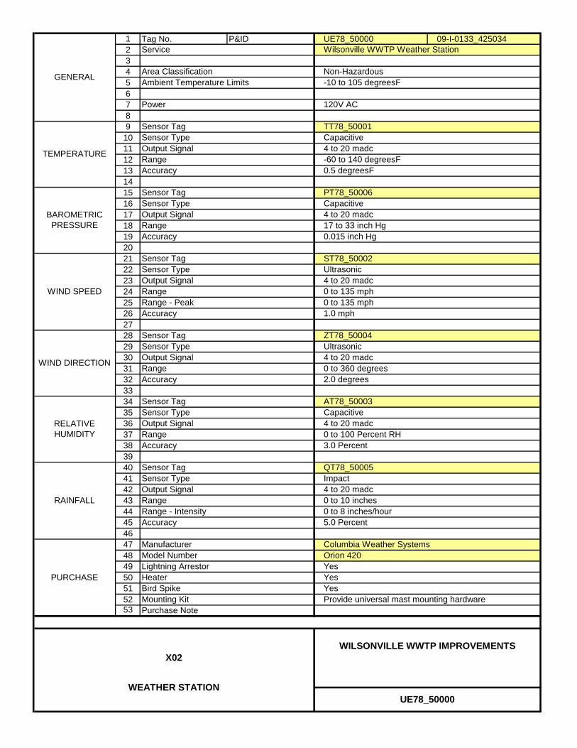
1 Tag No. P&ID UE78_50000 09-I-0133_42503423456789
1011121314151617181920212223242526272829303132333435363738394041424344454647484950515253
Heater Yes
RELATIVE HUMIDITY Range 0 to 100 Percent RH
RAINFALL Range 0 to 10 inches
Accuracy 5.0 Percent
BAROMETRIC PRESSURE
WIND SPEED
WIND DIRECTION Range
Accuracy
3.0 Percent
ZT78_50004
0 to 135 mph0 to 135 mph
RangeAccuracy
-60 to 140 degreesF0.5 degreesF
Output Signal 4 to 20 madc
0.015 inch Hg
AT78_50003
Ambient Temperature Limits
Power
-10 to 105 degreesF
120V AC
1.0 mph
Sensor Type Ultrasonic
17 to 33 inch Hg
4 to 20 madc
Sensor Tag
Sensor Type
Capacitive
Capacitive4 to 20 madc
ST78_50002
Sensor Tag
ImpactQT78_50005
0 to 360 degrees
GENERAL
TEMPERATURE
Output Signal
Sensor TypeOutput Signal
Output Signal
Sensor Tag
RangeRange - Peak
PURCHASE
Service
Area Classification
Sensor TagSensor Type
RangeAccuracy
Accuracy
Wilsonville WWTP Weather Station
Non-Hazardous
TT78_50001
Sensor Type
Sensor Tag
Sensor Tag
Purchase Note
Lightning Arrestor
Provide universal mast mounting hardware
0 to 8 inches/hour
Columbia Weather Systems
Range - Intensity
ManufacturerModel Number
YesBird Spike
Orion 420
Sensor TypeOutput Signal
Ultrasonic4 to 20 madc
Yes
Accuracy
UE78_50000
WILSONVILLE WWTP IMPROVEMENTSX02
WEATHER STATION
Mounting Kit
4 to 20 madc
Capacitive
PT78_50006
2.0 degrees
Output Signal 4 to 20 madc
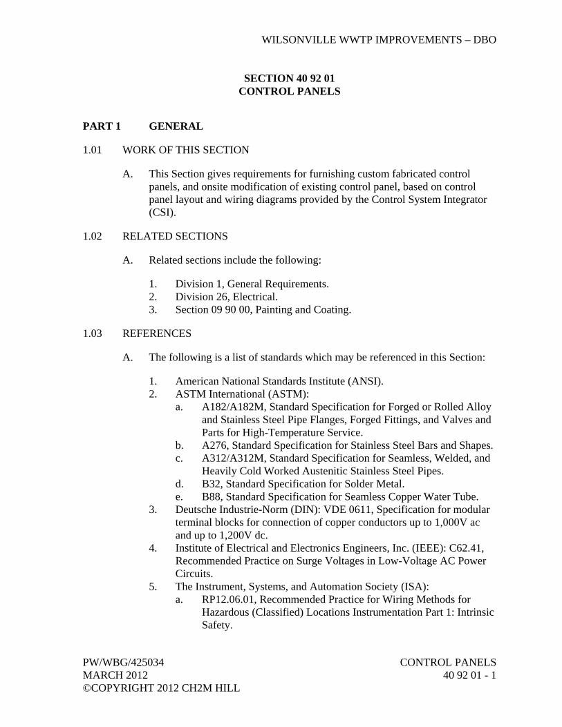
WILSONVILLE WWTP IMPROVEMENTS – DBO
PW/WBG/425034 CONTROL PANELS MARCH 2012 40 92 01 - 1 ©COPYRIGHT 2012 CH2M HILL
SECTION 40 92 01 CONTROL PANELS
PART 1 GENERAL
1.01 WORK OF THIS SECTION
A. This Section gives requirements for furnishing custom fabricated control panels, and onsite modification of existing control panel, based on control panel layout and wiring diagrams provided by the Control System Integrator (CSI).
1.02 RELATED SECTIONS
A. Related sections include the following:
1. Division 1, General Requirements. 2. Division 26, Electrical. 3. Section 09 90 00, Painting and Coating.
1.03 REFERENCES
A. The following is a list of standards which may be referenced in this Section:
1. American National Standards Institute (ANSI). 2. ASTM International (ASTM):
a. A182/A182M, Standard Specification for Forged or Rolled Alloy and Stainless Steel Pipe Flanges, Forged Fittings, and Valves and Parts for High-Temperature Service.
b. A276, Standard Specification for Stainless Steel Bars and Shapes. c. A312/A312M, Standard Specification for Seamless, Welded, and
Heavily Cold Worked Austenitic Stainless Steel Pipes. d. B32, Standard Specification for Solder Metal. e. B88, Standard Specification for Seamless Copper Water Tube.
3. Deutsche Industrie-Norm (DIN): VDE 0611, Specification for modular terminal blocks for connection of copper conductors up to 1,000V ac and up to 1,200V dc.
4. Institute of Electrical and Electronics Engineers, Inc. (IEEE): C62.41, Recommended Practice on Surge Voltages in Low-Voltage AC Power Circuits.
5. The Instrument, Systems, and Automation Society (ISA): a. RP12.06.01, Recommended Practice for Wiring Methods for
Hazardous (Classified) Locations Instrumentation Part 1: Intrinsic Safety.
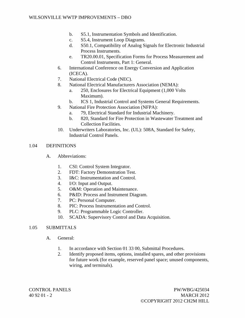
WILSONVILLE WWTP IMPROVEMENTS – DBO
CONTROL PANELS PW/WBG/425034 40 92 01 - 2 MARCH 2012 ©COPYRIGHT 2012 CH2M HILL
b. S5.1, Instrumentation Symbols and Identification. c. S5.4, Instrument Loop Diagrams. d. S50.1, Compatibility of Analog Signals for Electronic Industrial
Process Instruments. e. TR20.00.01, Specification Forms for Process Measurement and
Control Instruments, Part 1: General. 6. International Conference on Energy Conversion and Application
(ICECA). 7. National Electrical Code (NEC). 8. National Electrical Manufacturers Association (NEMA):
a. 250, Enclosures for Electrical Equipment (1,000 Volts Maximum).
b. ICS 1, Industrial Control and Systems General Requirements. 9. National Fire Protection Association (NFPA):
a. 79, Electrical Standard for Industrial Machinery. b. 820, Standard for Fire Protection in Wastewater Treatment and
Collection Facilities. 10. Underwriters Laboratories, Inc. (UL): 508A, Standard for Safety,
Industrial Control Panels.
1.04 DEFINITIONS
A. Abbreviations:
1. CSI: Control System Integrator. 2. FDT: Factory Demonstration Test. 3. I&C: Instrumentation and Control. 4. I/O: Input and Output. 5. O&M: Operation and Maintenance. 6. P&ID: Process and Instrument Diagram. 7. PC: Personal Computer. 8. PIC: Process Instrumentation and Control. 9. PLC: Programmable Logic Controller. 10. SCADA: Supervisory Control and Data Acquisition.
1.05 SUBMITTALS
A. General:
1. In accordance with Section 01 33 00, Submittal Procedures. 2. Identify proposed items, options, installed spares, and other provisions
for future work (for example, reserved panel space; unused components, wiring, and terminals).
WILSONVILLE WWTP IMPROVEMENTS – DBO
PW/WBG/425034 CONTROL PANELS MARCH 2012 40 92 01 - 3 ©COPYRIGHT 2012 CH2M HILL
B. Action Submittals:
1. General: Manufacture of the control panels shall not commence until related submittals have been approved by CH2M HILL’s Engineer.
2. Submittal Requirements: a. Catalog Cuts and Product Information: For I&C components,
electrical devices, and mechanical devices that are not supplied by the CSI: 1) Catalog information, marked to identify proposed items and
options. 2) Descriptive literature. 3) External power and signal connections. 4) Scaled drawings showing exterior dimensions and locations
of electrical and mechanical interfaces. b. Layout Drawings:
1) The CSI will provide control panel layout drawings including the following information: a) Front, rear, and internal panel views to scale. b) Dimensional information. c) Tag number and functional name of components
mounted in and on the panel. d) Product information on panel components provided by
the CSI. e) Nameplate location and legend including text, letter
size and colors to be used. f) Location of external wiring and/or piping connections. g) Mounting and installation details. h) Calculations for heating and cooling. i) Subpanel layouts and mounting details for all items
located inside control panels. 2) Submit neat and legible mark ups of the CSI drawings with
the following information: a) Product information on all panel components not
provided by the CSI. b) Location of anchoring connections and holes.
c. Wiring and/or Piping Diagrams: 1) The CSI will provide control panel wiring and/or piping
diagrams including the following information: a) Name of panel, console or cabinet. b) Wiring sizes and types. c) Piping sizes and types. d) Terminal strip numbers. e) Color coding.

WILSONVILLE WWTP IMPROVEMENTS – DBO
CONTROL PANELS PW/WBG/425034 40 92 01 - 4 MARCH 2012 ©COPYRIGHT 2012 CH2M HILL
f) For components supplied by the CSI, functional name and manufacturer’s designation for components to which wiring and piping are connected.
g) Wires: Wire number and color. Cable number if part of multiconductor cable.
h) Terminals: Location (enclosure number, terminal junction box number, or MCC number), terminal strip number, and terminal block number.
i) Components: (1) Tag number, terminal numbers, and location
(“FIELD,” enclosure number, or MCC number). (2) Switching action (open or close on rising or
falling process variable), setpoint value and units, and process variable description (for example, Sump Level High).
j) I/O Points: PLC unit number, I/O tag number, I/O address, terminal numbers, and terminal strip numbers.
k) Relay Coils: (1) Tag number and its function. (2) On right side of run where coil is located,
contact location by ladder number and sheet number. Underline normally closed contacts.
l) Relay Contacts: Coil tag number, function, and coil location (ladder rung number and sheet number).
m) Communications and Networks: Network type, address or node identification, port or channel number, and type of connector.
n) Ground wires, surge protectors, and connections. o) Wire and Cable Names: Names, wire number, and
wire color for circuits entering and leaving a panel. 2) Submit neat and legible mark ups of the CSI control panel
wiring and/or piping diagrams with the following information: a) For components not supplied by the CSI, functional
name and manufacturer’s designation for components to which wiring and piping are connected.
b) Revisions needed to correct incomplete or incorrect information.
d. Bill of Materials: 1) The CSI will provide a Bill of Materials for each panel
including tag number, functional name, manufacturer’s name, model number and quantity for all components
WILSONVILLE WWTP IMPROVEMENTS – DBO
PW/WBG/425034 CONTROL PANELS MARCH 2012 40 92 01 - 5 ©COPYRIGHT 2012 CH2M HILL
provided by the CSI mounted in or on the panel or enclosure.
2) Submit Bill of Materials for components not provided by the CSI.
e. Submit electronic copies of drawings markups in pdf format. f. Anchorage and bracing drawings and catalog information as
required by Section 01 88 15, Anchorage and Bracing, for loads in Section 01 61 00, Common Product Requirements.
C. Informational Submittals:
1. Manufacturer’s O&M manuals for components, electrical devices, and mechanical devices that are not provided by the CSI: a. In accordance with Section 01 78 23, Operation, Maintenance,
and Asset Data. b. Content for Each O&M Manual:
1) Table of Contents. 2) Operations procedures. 3) Installation requirements and procedures. 4) Maintenance requirements and procedures. 5) Troubleshooting procedures. 6) Calibration procedures. 7) Internal schematic and wiring diagrams.
2. Testing Related Submittals: a. Factory Demonstration Test:
1) Proposed test procedures, forms, and checklists. 2) Test Documentation: Copy of signed off test results.
3. Record Drawings and Documentation: a. Submit final markups of the CSI panel drawings, wiring diagrams,
and documentation to reflect any updates made to the panels during fabrication and testing.
b. Provide electronic copies of the markups in Adobe Acrobat pdf format.
4. Anchorage and bracing calculations as required by Section 01 88 15, Anchorage and Bracing, for loads in Section 01 61 00, Common Product Requirements.
1.06 QUALITY ASSURANCE
A. General: The Supplier shall supply its company’s Quality Assurance Plan. The plans shall include but not necessarily be limited to method of testing, raw material criteria, methods of documentation, station control, “Burn-In,” final tests and serialization coding and packaging.

WILSONVILLE WWTP IMPROVEMENTS – DBO
CONTROL PANELS PW/WBG/425034 40 92 01 - 6 MARCH 2012 ©COPYRIGHT 2012 CH2M HILL
B. Qualifications:
1. Financially sound with minimum of 5 years’ experience in designing and manufacturing similar control panels as required for this Project.
2. Have a UL approved panel shop. 3. Have a record of prompt shipments in accordance with contract
obligations required for previous projects.
1.07 DELIVERY, STORAGE, AND HANDLING
A. In accordance with Section 01 61 00, Common Product Requirements.
B. Packaged at the factory prior to shipment to protect each item from damage during shipment and storage. Containers protected against impact, abrasion, corrosion, discoloration and/or other damages. Clearly label contents of each container and provide information on the required storage conditions necessary for the equipment.
C. Notify the CSI of the storage requirements and recommendations for the equipment prior to shipment.
D. Prior to shipment, include corrosive inhibitive vapor capsules in shipping containers, and related equipment as recommended by capsule manufacturer.
1.08 SEQUENCING AND SCHEDULING
A. Prerequisite Activities and Lead Times: Do not start following key Project activities until prerequisite activities and lead times listed below have been completed and satisfied:
1. Test Prerequisite: Associated test procedures Submittals completed. 2. Factory Demonstration Test Prerequisite:
a. Approval of Control Panel submittals. b. Test procedures submittals completed.
3. Control Panels Shipment to Site: a. Prerequisites:
1) Approval of Shop Drawings. 2) Factory Demonstration Test (FDT) completed.
PART 2 PRODUCTS
2.01 GENERAL
A. Provide control panels listed in the Control Panel Schedule in Article Supplements at end of this Section, and in accordance with the control panel layout drawings and wiring diagrams provided by the CSI.
WILSONVILLE WWTP IMPROVEMENTS – DBO
PW/WBG/425034 CONTROL PANELS MARCH 2012 40 92 01 - 7 ©COPYRIGHT 2012 CH2M HILL
B. Like Equipment Items: Use products of one manufacturer and of the same series or family of models to achieve standardization for appearance, operation, maintenance, spare parts, and manufacturer’s services.
2.02 CONTROL PANEL COMPONENTS
A. Provide all components and hardware not provided by the CSI necessary to make each control panel fully operational and in conformance with requirements specified in this Section.
2.03 EXISTING PANEL MODIFICATIONS
A. Gravity Belt Thickener Panel LCP80-04:
1. Remove the following front panel mounted items and install cover plates to cover and seal the holes: a. Touchscreen Operator Interface Unit. b. Biosolids Pump START/STOP switches and SPEED CONTROL
potentiometer. c. Washwater Pumps 1 and 2 PLC/OFF/BYPASS switches. d. WAS Pumps 1 and 2 START/STOP switches.
2. Replace existing PLC with new PLC provided by the CSI. 3. Rewire new PLC in accordance with wiring diagrams provided by the
CSI.
2.04 SERVICE CONDITIONS
A. Service Conditions for Panels: As noted in Control Panel Schedule located in Article Supplements at end of this Section. Design panels for continuous operation in these environments:
1. Freestanding Panel and Consoles: a. Inside: NEMA 12. b. Outside: NEMA 4X. c. Inside, Hazardous: NEMA 7. d. Outside, Hazardous: NEMA 7.
2. Smaller Panels and Assemblies (that are not freestanding): a. Inside, Air Conditioned: NEMA 12. b. All Other Locations: NEMA 4X. c. Inside, Hazardous: NEMA 7. d. Outside, Hazardous: NEMA 7.
WILSONVILLE WWTP IMPROVEMENTS – DBO
CONTROL PANELS PW/WBG/425034 40 92 01 - 8 MARCH 2012 ©COPYRIGHT 2012 CH2M HILL
2.05 NAMEPLATES AND TAGS
A. Panel Nameplates: For identification of panels and components mounted thereon.
1. Nameplate Size and Material: 3/32-inch thick laminated phenolic type with black matte finish surface and white letter engraving.
2. Panel Identification Nameplates: 1/2-inch high letter engravings. 3. Panel Mounted Component (e.g., Control Devices, Indicating Lights,
Selector Switches, etc.) Identification Nameplates: 1/4-inch high letter engravings.
4. Attached to the panel face with two stainless steel self-tapping screws. 5. Nameplate Engravings: Include the instrument or equipment tag number
and descriptive title as shown and specified.
B. Internally Mounted Instruments Tags:
1. Tag Numbers: As listed in the Contract Documents. 2. Identifying Tag Number: Permanently etched or embossed onto a
stainless steel tag which shall be fastened to the device housing with stainless steel rivets or self tapping screws of appropriate size.
3. Where neither of the above fastenings can be accomplished, tags shall be permanently attached to the device by a circlet of 1/16-inch diameter stainless steel wire rope.
4. Identification Tag: Installed so that the numbers are easily visible to service personnel.
5. Front of Panel Mounted Instruments: Tag attached to rear of device.
C. Tagging of the following items shall be accomplished with the use of adhesive plastic Brady USA, Inc. labels, or equal.
1. Tag all electrical devices (e.g., relays, timers, power supplies) mounted within control panels and enclosures.
2. Tag all pneumatic lines. 3. Numerically tag all terminal blocks. 4. Numerically tag wiring at each end.
D. Legend Plates for Panel Mounted Pushbuttons, Lights, and Switches.
1. Inscription: a. Refer to table under Paragraph Standard Pushbutton Colors and
Inscriptions. b. Refer to table under Paragraph Standard Light Colors and
Inscriptions. c. Refer to P&IDs and panel Drawings.

WILSONVILLE WWTP IMPROVEMENTS – DBO
PW/WBG/425034 CONTROL PANELS MARCH 2012 40 92 01 - 9 ©COPYRIGHT 2012 CH2M HILL
2. Materials: Stainless steel, keyed legend plates. Secured to panel by mounting nut for pushbutton, light, or switch.
3. Letters: Black on gray or white background.
E. Service Legends: Component identification nameplate located on face of component.
1. Inscription: As shown on panel drawing. 2. Materials: Adhesive-backed, laminated plastic. 3. Letters: 3/16-inch-high, white on black background, unless otherwise
noted.
F. Nametags: Component identification for field devices.
1. Inscription: Component tag number. 2. Materials: 16-gauge, Type 304 stainless steel. 3. Letters: 3/16-inch-high, imposed. 4. Mounting: Affix to component with 16-gauge or 18-gauge stainless
steel wire rope or stainless steel screws.
2.06 MECHANICAL SYSTEM COMPONENTS
A. Flow Element, Rotameter, Purge:
1. For air or water service, unless otherwise noted. 2. Materials: Glass tube, fiberglass body, stainless steel float, nylon ball
check valve. 3. Direct-Reading Scale Length: 2-1/2 inches, minimum. 4. Scale Ranges: 0 to 2.5 scfh for air service or 0 to 10 gph for water
service. 5. Integral inlet needle valves. 6. Integral Differential Pressure Regulators:
a. For water service. b. For air service for level ranges greater than 10 feet of water.
7. Rotameters for water service. 8. Manufacturers and Products:
a. Fischer & Porter; Series 10A3130. b. Brooks; Series DS-1350.
B. Manifold, Two-Valve Block and Bleed:
1. Type: For isolation, calibration, and venting of pressure instruments. 2. Materials: Stainless steel.

WILSONVILLE WWTP IMPROVEMENTS – DBO
CONTROL PANELS PW/WBG/425034 40 92 01 - 10 MARCH 2012 ©COPYRIGHT 2012 CH2M HILL
3. Manufacturer and Product: a. Anderson Greenwood; Type M25. b. Or equal.
C. Manifold, Three-Valve Equalizing:
1. Type: For isolation and equalization of differential pressure transducers. 2. Materials: Stainless steel. 3. Manufacturers and Products:
a. Anderson, Greenwood and Co.; Type M1. b. Evans.
D. Pressure Gauge: For other than process variable measurement.
1. Dial Size: Nominal 2-inch dial size. 2. Accuracy: 2 percent of span. 3. Scale Range: Such that normal operating pressure lies between
50 percent and 80 percent of scale range. 4. Connection: 1/4-inch NPT through bottom, unless otherwise noted. 5. Manufacturers and Products:
a. Ashcroft Utility; Gauge Series 1000. b. Marsh; Standard Gauge Series. c. Ametek U.S.; Gauge Series P500. d. Acculite; Series 2000.
E. Valve, Needle:
1. Materials: Brass, stainless steel, PVC, or CPCV, as recommended by manufacturer for designated service, unless otherwise shown on Drawings.
2. Size: 0.020-inch orifice. 3. Manufacturers and Products:
a. Whitey; Model 21RF2. b. Hoke; 3700 Series.
F. ON/OFF Valves:
1. Type: Ball valve. 2. Materials: Brass, stainless steel, PVC, or CPCV, as recommended by
manufacturer for designated service, unless otherwise shown on Drawings.
3. Manufacturers and Products: a. Whitey; Series 41 through Series 43. b. Hoke; Flomite 7100 Series.
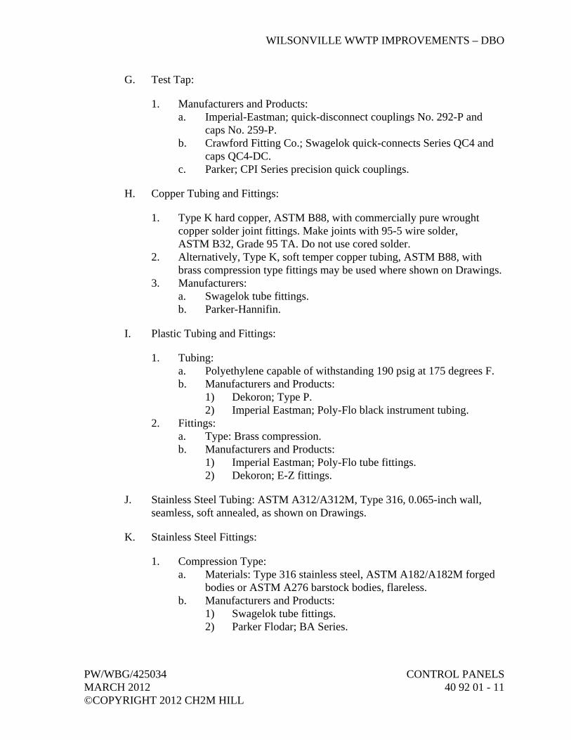
WILSONVILLE WWTP IMPROVEMENTS – DBO
PW/WBG/425034 CONTROL PANELS MARCH 2012 40 92 01 - 11 ©COPYRIGHT 2012 CH2M HILL
G. Test Tap:
1. Manufacturers and Products: a. Imperial-Eastman; quick-disconnect couplings No. 292-P and
caps No. 259-P. b. Crawford Fitting Co.; Swagelok quick-connects Series QC4 and
caps QC4-DC. c. Parker; CPI Series precision quick couplings.
H. Copper Tubing and Fittings:
1. Type K hard copper, ASTM B88, with commercially pure wrought copper solder joint fittings. Make joints with 95-5 wire solder, ASTM B32, Grade 95 TA. Do not use cored solder.
2. Alternatively, Type K, soft temper copper tubing, ASTM B88, with brass compression type fittings may be used where shown on Drawings.
3. Manufacturers: a. Swagelok tube fittings. b. Parker-Hannifin.
I. Plastic Tubing and Fittings:
1. Tubing: a. Polyethylene capable of withstanding 190 psig at 175 degrees F. b. Manufacturers and Products:
1) Dekoron; Type P. 2) Imperial Eastman; Poly-Flo black instrument tubing.
2. Fittings: a. Type: Brass compression. b. Manufacturers and Products:
1) Imperial Eastman; Poly-Flo tube fittings. 2) Dekoron; E-Z fittings.
J. Stainless Steel Tubing: ASTM A312/A312M, Type 316, 0.065-inch wall, seamless, soft annealed, as shown on Drawings.
K. Stainless Steel Fittings:
1. Compression Type: a. Materials: Type 316 stainless steel, ASTM A182/A182M forged
bodies or ASTM A276 barstock bodies, flareless. b. Manufacturers and Products:
1) Swagelok tube fittings. 2) Parker Flodar; BA Series.

WILSONVILLE WWTP IMPROVEMENTS – DBO
CONTROL PANELS PW/WBG/425034 40 92 01 - 12 MARCH 2012 ©COPYRIGHT 2012 CH2M HILL
3) Parker CPI tube fittings; Parker A-LOK dual ferrule tube fittings.
2. Socket Weld Type: a. Materials: Type 316 stainless steel, ASTM A182/A182M forged
bodies or ASTM A276 barstock bodies, 3,000 psi maximum working pressure, safety factor 4:1.
b. Manufacturers: 1) Cajon. 2) Swagelok. 3) Parker WELDLOK.
L. Air Set: Consists of a shutoff valve, pressure regulator, discharge pressure gauge, and interconnecting tubing.
M. Tubing Raceways:
1. Cable tray systems complete with tees, elbows, reducers, and covers. 2. Size in accordance with manufacturer’s recommendations for intended
service. 3. Materials: Galvanized steel or aluminum brass as recommended by
manufacturer for designated service, unless otherwise shown on Drawings.
4. Manufacturers: a. Globetray. b. Cope.
2.07 ELECTRICAL REQUIREMENTS
A. I&C and electrical components, terminals, wires, and enclosures UL recognized or UL listed.
B. Wires within Enclosures:
1. ac Circuits: a. Type: 600-volt, Type MTW stranded copper. b. Size: For current to be carried, but not less than No. 18 AWG.
2. Analog Signal Circuits: a. Type: 600-volt stranded copper, twisted shielded pairs or triad
with a 100 percent, aluminum-polyester shield, rated 60 degrees C.
b. Panels with Circuits Less Than 600 volts: Rated at 600 volts. Belden No. 18 AWG Type 9341, Triad Beldon No. 1121A.
c. Size: No. 18 AWG, minimum.
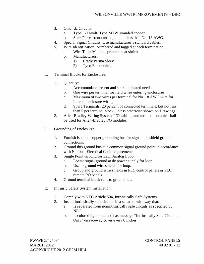
WILSONVILLE WWTP IMPROVEMENTS – DBO
PW/WBG/425034 CONTROL PANELS MARCH 2012 40 92 01 - 13 ©COPYRIGHT 2012 CH2M HILL
3. Other dc Circuits: a. Type: 600-volt, Type MTW stranded copper. b. Size: For current carried, but not less than No. 18 AWG.
4. Special Signal Circuits: Use manufacturer’s standard cables. 5. Wire Identification: Numbered and tagged at each termination.
a. Wire Tags: Machine printed, heat shrink. b. Manufacturers:
1) Brady Perma Sleev. 2) Tyco Electronics.
C. Terminal Blocks for Enclosures:
1. Quantity: a. Accommodate present and spare indicated needs. b. One wire per terminal for field wires entering enclosures. c. Maximum of two wires per terminal for No. 18 AWG wire for
internal enclosure wiring. d. Spare Terminals: 20 percent of connected terminals, but not less
than 5 per terminal block, unless otherwise shown on Drawings. 2. Allen-Bradley Wiring Systems I/O cabling and termination units shall
be used for Allen-Bradley I/O modules.
D. Grounding of Enclosures:
1. Furnish isolated copper grounding bus for signal and shield ground connections.
2. Ground this ground bus at a common signal ground point in accordance with National Electrical Code requirements.
3. Single Point Ground for Each Analog Loop: a. Locate signal ground at dc power supply for loop. b. Use to ground wire shields for loop. c. Group and ground wire shields in PLC control panels or PLC
remote I/O panels. 4. Ground terminal block rails to ground bus.
E. Intrinsic Safety System Installation:
1. Comply with NEC Article 504, Intrinsically Safe Systems. 2. Install intrinsically safe circuits in a separate wire way that:
a. Is separated from nonintrinsically safe circuits as specified by NEC.
b. Is colored light blue and has message “Intrinsically Safe Circuits Only” on raceway cover every 6 inches.

WILSONVILLE WWTP IMPROVEMENTS – DBO
CONTROL PANELS PW/WBG/425034 40 92 01 - 14 MARCH 2012 ©COPYRIGHT 2012 CH2M HILL
F. Electrical Transient Protection:
1. General: a. Function: Protect elements of PIC against damage due to
electrical transients induced in interconnecting lines by lightning and nearby electrical systems.
b. Provide and install surge suppressors at connection of ac power to control panels.
2. Surge Suppressor Types: a. General:
1) Construction: First-stage high-energy metal oxide varistor and second-stage bipolar silicon avalanche device separated by series impedance; includes grounding wire, stud, or terminal.
2) Response: 5 nanoseconds maximum. 3) Recovery: Automatic. 4) Temperature Range: Minus 20 degrees C to plus
85 degrees C. b. Suppressors on 120V ac Power Supply Connections:
1) Occurrences: Tested and rated for a minimum of 50 occurrences of IEEE C62.41 Category B test waveform.
2) First-Stage Clamping Voltage: 350 volts or less. 3) Second-Stage Clamping Voltage: 210 volts or less. 4) Continuous Operation: Power supplies for one four-wire
transmitter or receiver: 5 amps minimum at 130V ac. All other applications: 30 amps minimum at 130V ac.
c. Physical Characteristics: 1) Mounted in Enclosures: Encapsulated inflame retardant
epoxy. 2) Din rail mount. 3) For 120V ac Lines:
a) Plug: Phoenix Contact, PT 2-PE/S-120AC-ST. b) Base: Phoenix Contact, PT-BE/FM.
2.08 PANEL FABRICATION
A. General:
1. Nominal Panel Dimensions: Refer to control panel layout drawings. 2. Panel Construction and Interior Wiring: In accordance with the National
Electrical Code (NEC), state and local codes, and applicable sections of NEMA, ANSI, UL, and ICECA.
3. Fabricate panels, install instruments and wire, and plumb at panel Supplier’s facility. No fabrication other than correction of minor defects or minor transit damage permitted onsite.

WILSONVILLE WWTP IMPROVEMENTS – DBO
PW/WBG/425034 CONTROL PANELS MARCH 2012 40 92 01 - 15 ©COPYRIGHT 2012 CH2M HILL
4. UL Listing Mark for Enclosures: Mark stating “Listed Enclosed Industrial Control Panel” per UL 508A.
5. Electrical Work: In accordance with the applicable requirements of Division 26, Electrical.
B. Temperature Control:
1. Freestanding Panels: a. Nonventilated Panels: Size to adequately dissipate heat from
equipment mounted inside panel and on panel. b. Ventilated Panels:
1) Furnish with louvers and forced ventilation as required to prevent temperature buildup from equipment mounted inside panel and on panel.
2) For panels with backs against wall, furnish louvers on top and bottom of panel sides.
3) For panels without backs against wall, furnish louvers on top and bottom of panel back.
4) Louver Construction: Stamped sheet metal. 5) Ventilation Fans:
a) Furnish where required to provide adequate cooling. b) Create positive internal pressure within panel. c) Fan Motor Power: 120V ac, 60-Hz, thermostatically
controlled. 6) Air Filters: Washable aluminum, Hoffman Series A-FLT.
2. Smaller Panels (that are not freestanding): Size to adequately dissipate heat from equipment mounted inside panel and on panel face.
3. Space Heaters: a. Thermostatically controlled to maintain internal panel
temperatures above dewpoint. b. Refer to Control Panel Schedule in Article Supplements.
4. Enclosures installed outdoors or indoors in spaces that are not conditioned: a. For enclosures with programmable logic controllers,
microprocessors, or when noted: 1) Provide NEMA 4/4X side-mounted or top-mounted closed-
loop air conditioning unit. Size the unit to maintain temperatures inside the enclosure to no more than 45 degrees C with an ambient temperature of 50 degrees C in full sun and the equipment operating at full load.
2) Air Conditioner Power: 120 volts, provided by an external circuit, for loads not to exceed 15A. For loads greater than 15A at 120V, notify CH2M HILL and request direction.
3) See Control Panel Schedule in Article Supplements.

WILSONVILLE WWTP IMPROVEMENTS – DBO
CONTROL PANELS PW/WBG/425034 40 92 01 - 16 MARCH 2012 ©COPYRIGHT 2012 CH2M HILL
b. For Other Enclosures: Furnish thermostatically controlled fans with replaceable air filters to dissipate heat generated in the panel and heaters to maintain temperature above 40 degrees F. Provide thermostats to automatically control heating and cooling requirements to maintain the temperature inside the enclosure within the ratings of the components inside the enclosure.
C. Freestanding Panel Construction:
1. Materials: a. Indoor Installation: Sheet steel, unless otherwise shown on
Drawings. b. Outdoor Installations: Type 304 stainless steel with a white
powder coat finish. c. Minimum Thickness: 12-gauge, unless otherwise noted.
2. Panel Rating: a. Indoor: NEMA 12. b. Outdoor: NEMA 4X.
3. Panel Front: a. Fabricated from a single piece of sheet steel, unless otherwise
shown on Drawings. b. No seams or bolt heads visible when viewed from front. c. Panel Cutouts: Smoothly finished with rounded edges. d. Stiffeners: Steel angle or plate stiffeners or both on back of panel
face to prevent panel deflection under instrument loading or operation.
4. Internal Framework: a. Structural steel for instrument support and panel bracing. b. Permit panel lifting without racking or distortion.
5. Sub-panels for installation of relays and other internally mounted components.
6. Lifting rings to allow simple, safe rigging and lifting of panel during installation.
7. Adjacent Panels: Securely bolted together so front faces are parallel. 8. Door:
a. Full height, fully gasketed access door where shown on Drawings. b. Latch: Three-point, Southco Type 44. c. Handle: “D” ring, foldable type. d. Hinges: Full-length, continuous, piano-type, steel hinges with
stainless steel pins. e. Rear Access: Extend no further than 24 inches beyond panel when
opened to 90-degree position. f. Front and Side Access Doors: As shown on Drawings.
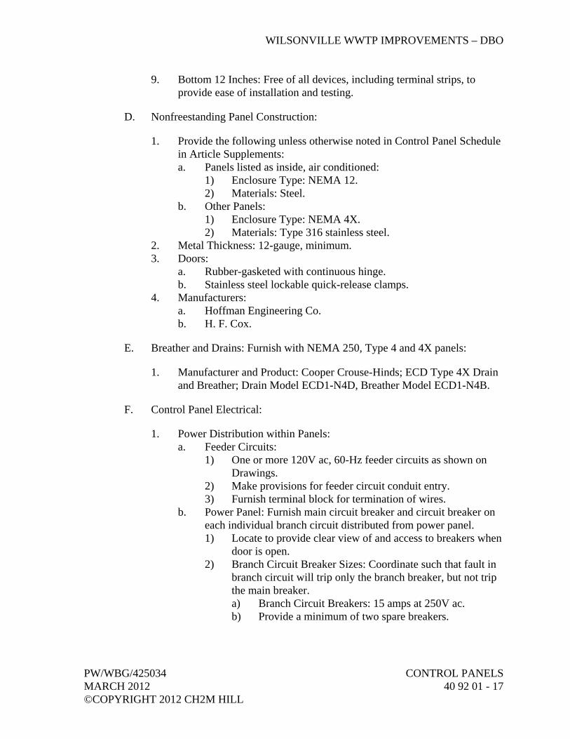
WILSONVILLE WWTP IMPROVEMENTS – DBO
PW/WBG/425034 CONTROL PANELS MARCH 2012 40 92 01 - 17 ©COPYRIGHT 2012 CH2M HILL
9. Bottom 12 Inches: Free of all devices, including terminal strips, to provide ease of installation and testing.
D. Nonfreestanding Panel Construction:
1. Provide the following unless otherwise noted in Control Panel Schedule in Article Supplements: a. Panels listed as inside, air conditioned:
1) Enclosure Type: NEMA 12. 2) Materials: Steel.
b. Other Panels: 1) Enclosure Type: NEMA 4X. 2) Materials: Type 316 stainless steel.
2. Metal Thickness: 12-gauge, minimum. 3. Doors:
a. Rubber-gasketed with continuous hinge. b. Stainless steel lockable quick-release clamps.
4. Manufacturers: a. Hoffman Engineering Co. b. H. F. Cox.
E. Breather and Drains: Furnish with NEMA 250, Type 4 and 4X panels:
1. Manufacturer and Product: Cooper Crouse-Hinds; ECD Type 4X Drain and Breather; Drain Model ECD1-N4D, Breather Model ECD1-N4B.
F. Control Panel Electrical:
1. Power Distribution within Panels: a. Feeder Circuits:
1) One or more 120V ac, 60-Hz feeder circuits as shown on Drawings.
2) Make provisions for feeder circuit conduit entry. 3) Furnish terminal block for termination of wires.
b. Power Panel: Furnish main circuit breaker and circuit breaker on each individual branch circuit distributed from power panel. 1) Locate to provide clear view of and access to breakers when
door is open. 2) Branch Circuit Breaker Sizes: Coordinate such that fault in
branch circuit will trip only the branch breaker, but not trip the main breaker. a) Branch Circuit Breakers: 15 amps at 250V ac. b) Provide a minimum of two spare breakers.

WILSONVILLE WWTP IMPROVEMENTS – DBO
CONTROL PANELS PW/WBG/425034 40 92 01 - 18 MARCH 2012 ©COPYRIGHT 2012 CH2M HILL
3) Sub-branch Circuit Breakers: a) Provide as required to distribute power to PLC I/O
circuits and 120V ac field instruments. b) Size circuit breakers as required to protect each sub-
branch circuit without tripping the associated branch circuit.
c) Provide a minimum of two spare breakers. 4) Breaker Manufacturers and Products: Refer to Division 26.
c. Circuit Wiring: P&IDs and Control Diagrams on Drawings show function only. Use following rules for actual circuit wiring: 1) Devices on Single Circuit: 20, maximum. 2) Multiple Units Performing Parallel Operations: To prevent
failure of any single branch circuit from shutting down entire operation, do not group all units on same branch circuit.
3) Branch Circuit Loading: 12 amperes continuous, maximum. 4) Panel Lighting and Service Outlets: Put on separate 15-amp,
120V ac branch circuit. 5) Provide 120V ac plugmold for panel components with line
cords. 2. Signal Distribution:
a. Signal Wiring: Separate analog signal cables from power and control within a panel and cross at right angles where necessary.
b. Within Panels: 4 to 20 mA dc signals may be distributed as 1V dc to 5V dc.
c. Outside Panels: Isolated 4 to 20 mA dc only. d. Signal Wiring: Twisted shielded pairs. e. RTD and Thermocouple Extension Cable:
1) Continuous field to panel with no intermediate junction boxes or terminations.
2) RTDs in motor windings are considered a 600-volt circuit. 3) Terminate thermocouple extension wire directly to loop
instrument. 3. Signal Switching:
a. Use dry circuit type relays or switches. b. No interruption of 4 to 20 mA loops during switching. c. Switching Transients in Associated Signal Circuit:
1) 4 to 20 mA dc Signals: 0.2 mA, maximum. 2) 1V dc to 5V dc Signals: 0.05V, maximum.
4. Push-to-Test Circuitry: For each push-to-test indicating light, provide a fused push-to-test circuit.
5. Internal Panel Lights and Switch for Freestanding Panels: a. Type: Switched 40-watt fluorescent back-of-panel lights. b. Quantity: One light for every 4 feet of panel width.

WILSONVILLE WWTP IMPROVEMENTS – DBO
PW/WBG/425034 CONTROL PANELS MARCH 2012 40 92 01 - 19 ©COPYRIGHT 2012 CH2M HILL
c. Mounting: Inside and in the top of back-of-panel area. d. Protective metal shield for lights. e. One 120V ac, 20A, snap switch, to turn on the lights, mounted in
an outlet box with a cover and located so that it is easily accessible from access door.
6. Service Outlets for Freestanding Panels: a. Type: Three-wire, 120-volt, 20-ampere, GFCI GFCI duplex
receptacles. b. Quantity:
1) Panels 4 Feet Wide and Smaller: One. 2) Panels Larger than 4 Feet Wide: One for every 4 feet of
panel width, two minimum per panel. c. Mounting: Evenly spaced along back-of-panel area.
7. Internal Panel Lights and Service Outlets for Smaller Panels: a. Internal Panel Light and Switch: Switched 40-watt fluorescent
light. One 120V ac, 20A, snap switch, to turn on the light, mounted in an outlet box with a cover and located so that it is easily accessible from access door.
b. Service Outlet: Breaker protected 120-volt, 20-amp, GFCI GFCI duplex receptacle:
c. Required for panels. Refer to Control Panel Schedule in Article Supplements.
8. Standard Pushbutton Colors and Inscriptions: a. Use following unless otherwise noted in Instrument List:
Tag Function Inscription(s) Color
OO ON OFF
Black Black
OC OPEN CLOSE
Black Black
OCA OPEN CLOSE AUTO
Black Black Black
OOA ON OFF
AUTO
Black Black Black
MA MANUAL AUTO
Black Black
SS START STOP
Black Red
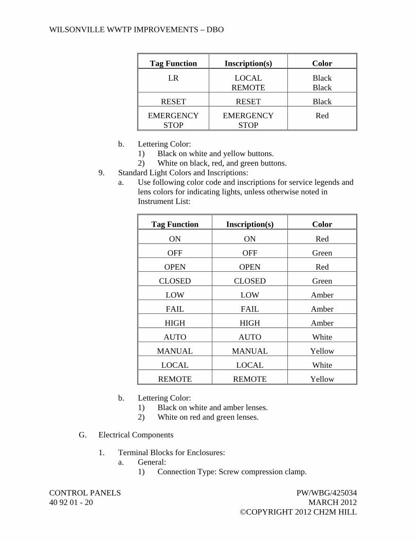
WILSONVILLE WWTP IMPROVEMENTS – DBO
CONTROL PANELS PW/WBG/425034 40 92 01 - 20 MARCH 2012 ©COPYRIGHT 2012 CH2M HILL
Tag Function Inscription(s) Color
LR LOCAL REMOTE
Black Black
RESET RESET Black
EMERGENCY STOP
EMERGENCY STOP
Red
b. Lettering Color: 1) Black on white and yellow buttons. 2) White on black, red, and green buttons.
9. Standard Light Colors and Inscriptions: a. Use following color code and inscriptions for service legends and
lens colors for indicating lights, unless otherwise noted in Instrument List:
Tag Function Inscription(s) Color
ON ON Red
OFF OFF Green
OPEN OPEN Red
CLOSED CLOSED Green
LOW LOW Amber
FAIL FAIL Amber
HIGH HIGH Amber
AUTO AUTO White
MANUAL MANUAL Yellow
LOCAL LOCAL White
REMOTE REMOTE Yellow
b. Lettering Color: 1) Black on white and amber lenses. 2) White on red and green lenses.
G. Electrical Components
1. Terminal Blocks for Enclosures: a. General:
1) Connection Type: Screw compression clamp.

WILSONVILLE WWTP IMPROVEMENTS – DBO
PW/WBG/425034 CONTROL PANELS MARCH 2012 40 92 01 - 21 ©COPYRIGHT 2012 CH2M HILL
2) Compression Clamp: a) Complies with DIN-VDE 0611. b) Hardened steel clamp with transversal grooves that
penetrate wire strands providing a vibration-proof connection.
c) Guides strands of wire into terminal. 3) Screws: Hardened steel, captive, and self-locking. 4) Current Bar: Copper or treated brass. 5) Insulation:
a) Thermoplastic rated for minus 55 degrees C to plus 110 degrees C.
b) Two funneled shaped inputs to facilitate wire entry. 6) Mounting:
a) Standard DIN rail. b) Terminal block can be extracted from an assembly
without displacing adjacent blocks. c) End Stops: Minimum of one at each end of rail.
7) Wire Preparation: Stripping only permitted. 8) Jumpers: Allow jumper installation without loss of space on
terminal or rail. 9) Marking System:
a) Terminal number shown on both sides of terminal block.
b) Allow use of preprinted and field marked tags. c) Terminal strip numbers shown on end stops. d) Mark terminal block and terminal strip numbers as
shown on panel control diagrams and loop diagrams. e) Fuse Marking for Fused Terminal Blocks: Fuse
voltage and amperage rating shown on top of terminal block.
b. Terminal Block, General Purpose: 1) Rated Voltage: 600V ac. 2) Rated Current: 30 amp. 3) Wire Size: 24 to 10 AWG. 4) Rated Wire Size: 10 AWG. 5) Color: Gray body. 6) Spacing: 1/4-inch, maximum. 7) Manufacturers:
a) Weidmuller. b) Entrelec. c) Or equal.
c. Terminal Block, Ground: 1) Wire Size: 24 to 10 AWG. 2) Rated Wire Size: 10 AWG.
WILSONVILLE WWTP IMPROVEMENTS – DBO
CONTROL PANELS PW/WBG/425034 40 92 01 - 22 MARCH 2012 ©COPYRIGHT 2012 CH2M HILL
3) Color: Green and yellow body. 4) Spacing: 1/4-inch, maximum. 5) Grounding: Electrically grounded to mounting rail. 6) Manufacturers:
a) Weidmuller. b) Entrelec. c) Or equal.
d. Terminal Block, Blade Disconnect Switch: 1) Rated Voltage: 600V ac. 2) Rated Current: 10 amp. 3) Wire Size: 22 to 10 AWG. 4) Rated Wire Size: 10 AWG. 5) Color: Gray body, orange switch. 6) Spacing: 1/4-inch, maximum. 7) Manufacturers:
a) Weidmuller. b) Entrelec. c) Or equal.
e. Terminal Block Diode: 1) Rated Voltage: 24V dc. 2) Rated Current: 30 ma. 3) Wire Size: 16 AWG. 4) Manufacturers:
a) Phoenix Contact. b) Or equal.
f. Terminal Block, Fused, 24V dc: 1) Rated Voltage: 600V dc. 2) Rated Current: 25 amp. 3) Wire Size: 22 to 10 AWG. 4) Rated Wire Size: 10 AWG. 5) Color: Gray body. 6) Fuse: 1/4- inch by 1-1/4 inches. 7) Indication: LED diode 24V dc. 8) Spacing: 0.512 inch, maximum. 9) Manufacturers:
a) Schneider Electric/Square D. b) Entrelec. c) Or equal.
g. Terminal Block, Fused, 120V ac: 1) Rated Voltage: 600V ac. 2) Rated Current: 25 amp. 3) Wire Size: 22 to 10 AWG. 4) Rated Wire Size: 10 AWG. 5) Color: Gray body.
WILSONVILLE WWTP IMPROVEMENTS – DBO
PW/WBG/425034 CONTROL PANELS MARCH 2012 40 92 01 - 23 ©COPYRIGHT 2012 CH2M HILL
6) Fuse: 1/4- inch by 1-1/4 inches. 7) Indication: Neon lamp, 110V ac. 8) Leakage Current: 1.8 mA, maximum. 9) Spacing: 0.512 inch, maximum. 10) Manufacturers:
a) Schneider Electric/Square D. b) Entrelec. c) Or equal.
h. Terminal Block, Fused, 120V ac, High Current: 1) Rated Voltage: 600V ac. 2) Rated Current: 35 amps. 3) Wire Size: 18 to 8 AWG. 4) Rated Wire Size: 8 AWG. 5) Color: Gray. 6) Fuse: 13/32-inch by 1-1/2 inches. 7) Spacing: 0.95-inch, maximum. 8) Manufacturers:
a) Schneider Electric/Square D. b) Entrelec. c) Or equal.
2. Relays: a. General:
1) Relay Mounting: Plug-in type socket. 2) Relay Enclosure: Furnish dust cover. 3) Socket Type: Screw terminal interface with wiring. 4) Socket Mounting: Rail. 5) Provide holddown clips.
b. Signal Switching Relay: 1) Type: Dry circuit. 2) Contact Arrangement: 2 Form C contacts. 3) Contact Rating: 5 amps at 28V dc or 120V ac. 4) Contact Material: Gold or silver. 5) Coil Voltage: As noted or shown. 6) Coil Power: 0.9 watt (dc), 1.2VA (ac). 7) Expected Mechanical Life: 10,000,000 operations. 8) Expected Electrical Life at Rated Load: 100,000 operations. 9) Indication Type: Neon or LED indicator lamp. 10) Seal Type: Hermetically sealed case. 11) Manufacturer and Product: Potter and Brumfield;
Series KH/KHA. c. Control Circuit Switching Relay, Nonlatching:
1) Type: Compact general purpose plug-in. 2) Contact Arrangement: 3 Form C contacts.

WILSONVILLE WWTP IMPROVEMENTS – DBO
CONTROL PANELS PW/WBG/425034 40 92 01 - 24 MARCH 2012 ©COPYRIGHT 2012 CH2M HILL
3) Contact Rating: 10A at 28V dc or 120V ac, and 6.6A at 240V ac.
4) Contact Material: Silver cadmium oxide alloy. 5) Coil Voltage: As noted or shown. 6) Coil Power: 1.8 watts (dc), 2.7VA (ac). 7) Expected Mechanical Life: 10,000,000 operations. 8) Expected Electrical Life at Rated Load: 100,000 operations. 9) Indication Type: Neon or LED indicator lamp. 10) Push-to-test button. 11) Manufacturer and Product: Potter and Brumfield;
Series KUP. d. Control Circuit Switching Relay, Latching:
1) Type: Dual coil mechanical latching relay. 2) Contact Arrangement: 2 Form C contacts. 3) Contact Rating: 10A at 28V dc or 120V ac. 4) Contact Material: Silver cadmium oxide alloy. 5) Coil Voltage: As noted or shown. 6) Coil Power: 2.7 watts (dc), 5.3VA (ac). 7) Expected Mechanical Life: 500,000 operations. 8) Expected Electrical Life at Rated Load: 50,000 operations. 9) Manufacturer and Product: Potter and Brumfield;
Series KB/KBP. e. Control Circuit Switching Relay, Time Delay:
1) Type: Adjustable time delay relay. 2) Contact Arrangement: 2 Form C contacts. 3) Contact Rating: 10A at 30V dc or 277V ac. 4) Contact Material: Silver cadmium oxide alloy. 5) Coil Voltage: As noted or shown. 6) Operating Temperature: Minus 10 degrees C to
55 degrees C. 7) Repeatability: Plus or minus 2 percent. 8) Delay Time Range: Select range such that time delay
setpoint fall between 20 percent to 80 percent of range. 9) Time Delay Setpoint: As noted or shown. 10) Mode of Operation: As noted or shown. 11) Adjustment Type: Integral potentiometer with knob external
to dust cover. 12) Manufacturer and Products: Potter and Brumfield;
Series CB for 0.1-second to 100-minute delay time ranges, Series CK for 0.1-second to 120-second delay time ranges.
3. Intrinsically Safe Relays: a. Monitor discrete contact signals that originate in a hazardous area
that are connected to an intrinsically safe relay located in a safe area.
WILSONVILLE WWTP IMPROVEMENTS – DBO
PW/WBG/425034 CONTROL PANELS MARCH 2012 40 92 01 - 25 ©COPYRIGHT 2012 CH2M HILL
b. Approved for use with input contacts located in Class I, II, and III hazardous locations.
c. Power: 120V ac. d. Output Contacts: SPDT rated for 5 amps minimum at 120V ac. e. Manufacturers and Products:
1) MTL, Inc.; Series MTL 2000. 2) Square D; Class 8501 – Type TO.
4. Power Supplies: a. Furnish as required to power instruments requiring external dc
power, including two-wire transmitters and dc relays. Provide dual power supplies with diode auctioneered outputs.
b. Convert 120V ac, 60-Hz power to dc power of appropriate voltage(s) with sufficient voltage regulation and ripple control to assure that instruments being supplied can operate within their required tolerances.
c. Provide output over voltage and over current protective devices to: 1) Protect instruments from damage due to power supply
failure. 2) Protect power supply from damage due to external failure.
d. Enclosures: NEMA 1. e. Mount such that dissipated heat does not adversely affect other
components. f. Fuses: For each dc supply line to each individual two-wire
transmitter. 1) Type: Indicating. 2) Mount so fuses can be easily seen and replaced.
g. Manufacturer and Product: Sola; Son Series. 5. Intrinsic Safety Barriers:
a. Intrinsically Safe Relays: Monitor discrete signals that originate in hazardous area and are used in a safe area. 1) Manufacturer: Phoenix Contact.
b. Intrinsically Safe Barriers: Interface analog signals as they pass from hazardous area to safe area. 1) Manufacturer: Phoenix Contact.
H. Control Panel Internal Wiring:
1. Restrain by plastic ties or ducts or metal raceways. 2. Hinge Wiring: Secure at each end so bending or twisting will be around
longitudinal axis of wire. Protect bend area with sleeve. 3. Arrange wiring neatly, cut to proper length, and remove surplus wire. 4. Provide abrasion protection for wire bundles that pass through holes or
across edges of sheet metal.

WILSONVILLE WWTP IMPROVEMENTS – DBO
CONTROL PANELS PW/WBG/425034 40 92 01 - 26 MARCH 2012 ©COPYRIGHT 2012 CH2M HILL
5. Connections to Screw Type Terminals: a. Locking-fork-tongue or ring-tongue lugs. b. Use manufacturer’s recommended tool with required sized anvil
to make crimp lug terminations. c. Wires terminated in a crimp lug, maximum of one. d. Lugs installed on a screw terminal, maximum of two.
6. Connections to Compression Clamp Type Terminals: a. Strip, prepare, and install wires in accordance with terminal
manufacturer’s recommendations. b. Wires installed in a compression screw and clamp, maximum of
one for field wires entering enclosure, otherwise maximum of two.
7. Splicing and tapping of wires, allowed only at device terminals or terminal blocks.
8. Terminate 24V dc and analog signal circuits on separate terminal block from ac circuit terminal blocks.
9. Separate analog and dc circuits by at least 6 inches from ac power and control wiring, except at unavoidable crossover points and at device terminations.
10. Arrange wiring to allow access for testing, removal, and maintenance of circuits and components.
11. Plastic Wire Duct Fill: Do not exceed manufacturer’s recommendations. 12. Conductors Carrying Foreign Voltages within a Panel:
a. Route foreign voltage conductors into panel and land on a circuit blade disconnect type terminal block.
b. Use wire with pink insulation to identify foreign voltage circuits within panel from terminal block on. Do not use wires with pink insulation for any other purpose.
13. Harness Wiring: a. 120V ac: No. 14 AWG, MTW. b. 24V dc: No. 16 AWG, MTW where individual conductors are
used and Type TC shielded tray cable where shielded wire is used. 14. Panelwork:
a. No exposed connections. b. Allow adjustments to equipment to be made without exposing
these terminals. c. For power and control wiring operating above 80V ac or dc use
covered channels or EMT raceways separate from low voltage signal circuits.
15. Plastic Wire Ducts Color: a. 120V ac: White. b. 24V dc: Gray. c. Communications Cables and Fiber Optic Jumpers: Orange.

WILSONVILLE WWTP IMPROVEMENTS – DBO
PW/WBG/425034 CONTROL PANELS MARCH 2012 40 92 01 - 27 ©COPYRIGHT 2012 CH2M HILL
16. Provide a communications plastic wire duct for communications cables and fiber optic cables between the communications devices in control panel and communications raceways. Design plastic wire duct design to take into account the minimum bending radius of the communications cable.
17. Make plastic wire ducts the same depth. 18. Provide a minimum of 1-1/2 inches between plastic wire ducts and
terminal blocks.
I. Control Relay Arrangement: Install control relays associated with specific loops in same panel section as corresponding terminal blocks or side panels. Provide 20 percent space for future relays. Locate spare space in same sections as spare terminal blocks.
J. Factory Finishing:
1. Furnish materials and equipment with manufacturer’s standard finish system in accordance with Section 09 90 00, Painting and Coating.
2. Use specific color if indicated. Otherwise use manufacturer’s standard finish color, or light gray if manufacturer has no standard color.
3. Stainless Steel and Aluminum: Not painted. 4. Nonmetallic Panels: Not painted. 5. Steel Panels:
a. Sand panel and remove mill scale, rust, grease, and oil. b. Fill imperfections and sand smooth. c. Paint panel interior and exterior with one coat of epoxy coating
metal primer, two finish coats of two-component type epoxy enamel.
d. Sand surfaces lightly between coats. e. Dry Film Thickness: 3 mils, minimum. f. Color: Manufacturer’s standard.
2.09 CORROSION PROTECTION
A. Corrosion-Inhibiting Vapor Capsules:
1. Use corrosion inhibiting vapor capsules in enclosures to protect components from corrosion.
2. Manufacturers and Products: a. Northern Instruments; Model Zerust VC. b. Hoffmann Engineering; Model A-HCI.
WILSONVILLE WWTP IMPROVEMENTS – DBO
CONTROL PANELS PW/WBG/425034 40 92 01 - 28 MARCH 2012 ©COPYRIGHT 2012 CH2M HILL
2.10 SOURCE QUALITY CONTROL
A. General:
1. CSI may actively participate in the tests. 2. CSI’s decision will be final regarding acceptability and completeness of
testing. 3. Procedures, Forms, and Checklists:
a. Except for Unwitnessed Factory Test, conduct tests in accordance with, and documented on, reviewed and accepted procedures, forms, and checklists.
b. Describe each test item to be performed. c. Have space after each test item description for sign off by
appropriate party after satisfactory completion. 4. Required Test Documentation: Test procedures, forms, and checklists
signed by CSI. 5. Conducting Tests:
a. Provide special testing materials and equipment. b. Provide suitable means of simulation of test inputs and outputs. c. Define simulation techniques in test procedures. d. Test Format: Cause and effect.
1) Person conducting test initiates an input (cause). 2) Specific test requirement is satisfied if correct result
(effect), occurs. e. Provide sufficient temporary software configuring to allow FDT
testing.
B. Unwitnessed Factory Test:
1. Scope: Inspect and test panels to ensure it is operational, ready for FDT. 2. Location: Panel Supplier’s facility.
C. Factory Demonstration Tests (FDT):
1. Notify CH2M HILL’s Engineer and CSI of test schedule 4 weeks prior to start of test.
2. Scope: Test entire control panel to demonstrate it is operational. 3. Location: Panel Supplier’s facility. 4. Temporary Application Software: Provide application software to allow
PLC and network testing including communications and input/output tests.
5. Correctness of wiring from panel field terminals to PLC system input/ output points and to panel components. a. Simulate each discrete signal at terminal strip. b. Simulate correctness of each analog signal using current source.
WILSONVILLE WWTP IMPROVEMENTS – DBO
PW/WBG/425034 CONTROL PANELS MARCH 2012 40 92 01 - 29 ©COPYRIGHT 2012 CH2M HILL
6. Operation of communications between PLCs and remote I/O and between PLCs and Ethernet devices including other PLCs, computers, and power monitors.
7. Correct deficiencies found and complete prior to shipment to Site. 8. Failed Tests: Repeat and witnessed by CSI. 9. Make following documentation available to CSI at test site both before
and during FDT: a. Drawings, Specifications, Addenda, and Change Orders. b. Master copy of FDT procedures. c. List of equipment to be tested including make, model, and serial
number. d. Approved hardware Shop Drawings for equipment being tested.
10. Daily Schedule for FDT: a. Begin each day with meeting to review day’s test schedule. b. End each day with each meeting to review day’s test results and to
review or revise next day’s test schedule.
PART 3 EXECUTION
3.01 SUPPLEMENT
A. The supplement listed below, following “End of Section,” is part of this Specification.
1. Control Panel Schedule.
END OF SECTION


WILSONVILLE WWTP IMPROVEMENTS
PW/WBG/425034 CONTROL PANELS MARCH 2012 40 92 01 SUPPLEMENT - 1 ©COPYRIGHT 2012 CH2M HILL
CONTROL PANEL SCHEDULE
Panel No. Service Mounting NEMA Design Detail
Dimensions H W D
(Maximum)
FDT Air
Conditioned
Serv. Lights, Outlets
Environment SS
CP10_01 Headworks PLC
Panel Free Standing 12
4091-389, 09-I-0215
90”x 36”x 24” (single access)
Yes No Yes Inside No
CP40_01 Secondary Treatment
PLC Panel Free Standing 12
4091-389, 09-I-0215
90”x 36”x 24” (dual access)
Yes No Yes Inside No
CP40_02 Solids Processing
PLC Panel Free Standing 12
4091-389, 09-I-0215
90”x 36”x 24” (dual access)
Yes No Yes Inside No
CP78_01 Dewatering & Drying
PLC Panel Free Standing 12
4091-389, 09-I-0215
90”x 36”x 24” (single access)
Yes No Yes Inside No
CP78_02 Dewatering & Drying
Radio Panel Wall Mount 12 4091-388 24”x24”x12” Yes No No Inside No
LCP80_04 GBT Control Panel Existing Panel
See Note 2 Existing See Note 2 Existing No Existing Existing Existing Existing
LCP80_04A GBT Auxiliary
Control Wall Mount 4X
4091-388, 09-I-0216
24”x24”x8” Yes No No Inside Yes
NIP10_01 Headworks Network
Interface Panel Free Standing 12
4091-389, 09-I-0212
72”x30”x 24” (single access)
Yes No No Inside No
NIP40_01 Process Gallery
Network Interface Panel
Free Standing 12 4091-389, 09-I-0212
72”x30”x 24” (dual access)
Yes No No Inside No
NIP70_01 UV Area Network
Interface Panel Stanchion
Mount 4X
4091-382, 09-I-0214
24”x18”x24” Yes No No Outside Yes
NIP78_01 Dewatering & Drying
Network Interface Panel
Free Standing 12 4091-389, 09-I-0212
72”x30”x 24” (dual access)
Yes No No Inside No

WILSONVILLE WWTP IMPROVEMENTS
CONTROL PANELS PW/WBG/425034 40 92 01 SUPPLEMENT - 2 MARCH 2012 ©COPYRIGHT 2012 CH2M HILL
Panel No. Service Mounting NEMA Design Detail
Dimensions H W D
(Maximum)
FDT Air
Conditioned
Serv. Lights, Outlets
Environment SS
NIP95_01 Operations Building Network Interface
Panel Free Standing n/a 09-I-0211
84”x54”x 36” (dual access)
Yes No No Inside No
Notes:
1. Column Descriptions:
a. FDT: Factory Demonstration Test required
b. Dimensions: Nominal space available for panel
c. SS: Stainless Steel (If entry is “No”, panel is Steel)
2. Existing GBT control panel to be field modified.

WILSONVILLE WWTP IMPROVEMENTS – DBO
PW/WBG/425034 PROGRAMMABLE LOGIC CONTROLLERS MARCH 2012 40 92 05 - 1 ©COPYRIGHT 2012 CH2M HILL
SECTION 40 92 05 PROGRAMMABLE LOGIC CONTROLLERS
PART 1 GENERAL
1.01 SUMMARY
A. This Section gives the requirements for furnishing programmable logic controllers (PLC) and accessories.
1.02 RELATED SECTIONS
A. Related sections include the following:
1. Division 1, General Requirements.
1.03 SUBMITTALS
A. General: In accordance with Section 01 33 00, Submittal Procedures.
B. Action Submittals:
1. Purchase Quotation: Listing of PLC components and accessories to be provided. Include applicable tag numbers and functional names of components.
2. Order Confirmation Summary: Final listing of PLC components and accessories to be provided.
3. PLC Equipment List: a. Neat and legible markups of the PLC Equipment List provided in
this Section. b. Markup the PLC Equipment List to include complete product
information and corrections to reflect all items in the purchase quotation.
C. Informational Submittals:
1. Operation and Maintenance Information: a. In accordance with Section 01 78 23, Operation, Maintenance,
and Asset Data. b. Provide sufficient detail to allow operation, removal, installation,
adjustment, calibration, maintenance and purchasing replacements for PLC components.
c. Name, address and telephone number of the PLC Supplier’s local service representative.
WILSONVILLE WWTP IMPROVEMENTS – DBO
PROGRAMMABLE LOGIC CONTROLLERS PW/WBG/425034 40 92 05 - 2 MARCH 2012 ©COPYRIGHT 2012 CH2M HILL
d. Complete list of supplied PLC components with full model numbers, including spare parts and test equipment provided.
2. Manufacturer’s Original Copies of Hardware, Software and Installation, Assembly and Operations Manuals for PLC components. Manuals shall include the following information: a. General descriptive information covering the basic features. b. Physical description covering layout and installation requirements
and all environmental constraints. c. Functional and operational descriptions covering the procedures
for programming, operation, startup, shutdown, and calibration of the PLC equipment and explaining how the various control functions are performed.
d. Principles of operation explaining the logic of operation; provide information covering operation to a component level.
e. Maintenance procedures covering checkout and troubleshooting: 1) Checkout procedures shall provide the means to verify the
satisfactory operation of equipment. 2) Troubleshooting procedures shall serve as a guide in
determining faulty components. f. Wiring and schematic diagrams. g. Safety considerations relating to operation and maintenance
procedures. 3. Content for Each O&M Manual:
a. Table of Contents. b. Operations procedures. c. Installation requirements and procedures. d. Maintenance requirements and procedures. e. Troubleshooting procedures. f. Internal schematic and wiring diagrams.
4. List of spares, expendables, test equipment and tools provided. 5. List of additional recommended spares, expendables, test equipment,
and tools. Include quantities, unit prices, and total costs. 6. Provide Manufacturer’s Certificate of Proper Installation.
1.04 DELIVERY, STORAGE, AND HANDLING
A. In accordance with Section 01 61 00, Common Product Requirements.
B. Packaged at the factory prior to shipment to protect each item from damage during shipment and storage. Containers protected against impact, abrasion, corrosion, discoloration and/or other damages. Clearly label contents of each container and provide information on the required storage conditions necessary for the equipment.

WILSONVILLE WWTP IMPROVEMENTS – DBO
PW/WBG/425034 PROGRAMMABLE LOGIC CONTROLLERS MARCH 2012 40 92 05 - 3 ©COPYRIGHT 2012 CH2M HILL
C. Notify CH2M HILL of the storage requirements and recommendations for the equipment prior to shipment.
D. Prior to shipment, include corrosive inhibitive vapor capsules in shipping containers, and related equipment as recommended by capsule manufacturer.
PART 2 PRODUCTS
2.01 GENERAL
A. Provide PLC components that are listed in the PLC Equipment List in Article Supplements at the end of this Section.
PART 3 EXECUTION
3.01 MANUFACTURER’S SERVICES
A. Manufacturer’s Certificate of Proper Installation: Provide for each PLC system identified in the PLC Equipment List.
3.02 SUPPLEMENTS
A. The supplements listed below, following “End of Section,” are part of this Specification.
1. PLC Equipment List. 2. I/O List - Hardwired. 3. I/O List - Network.
END OF SECTION


WILSONVILLE WWTP IMPROVEMENTS-DBO
PW/WBG/425034 PROGRAMMABLE LOGIC CONTROLLERS MARCH 2012 40 92 05 SUPPLEMENT - 1 ©COPYRIGHT 2012 CH2M HILL
PLC EQUIPMENT LIST
Name Description Qty. Model Manufacturer Comments
PLC10_01 PROGRAMMABLE CONTROLLER Location: CP10_01
Power Supply 2 1756-PA75R Allen-Bradley
Chassis Adapter Module 1 1756-PSCA2 Allen-Bradley
Chassis Adapter Cable 2 1756-CPR2 Allen-Bradley
ControlLogix 13 Slot IO Chassis 1 1756-A13 Allen-Bradley
ControlLogix CPU (Processor) 1 1756-L72 Allen-Bradley
ControlLogix Ethernet Communications Module 2 1756-EN2T Allen-Bradley
ControlLogix 16 Channel Analog Input Module 1 1756-IF16 Allen-Bradley
ControlLogix 8 Channel Analog Output Module 1 1756-OF8 Allen-Bradley
ControlLogix 16 Point Discrete Input Module 2 1756-IA16I Allen-Bradley
ControlLogix 16 Point Discrete Output Module 1 1756-OA16I Allen-Bradley
ControlLogix Slot Filler 5 1756-N2 Allen-Bradley
PLC40_01 PROGRAMMABLE CONTROLLER Location: CP40_01
Power Supply 2 1756-PA75R Allen-Bradley
Chassis Adapter Module 1 1756-PSCA2 Allen-Bradley
Chassis Adapter Cable 2 1756-CPR2 Allen-Bradley
ControlLogix 17 Slot IO Chassis 1 1756-A17 Allen-Bradley
ControlLogix CPU (Processor) 1 1756-L72 Allen-Bradley
ControlLogix Ethernet Communications Module 2 1756-EN2T Allen-Bradley
ControlLogix 16 Channel Analog Input Module 3 1756-IF16 Allen-Bradley
ControlLogix 8 Channel Analog Output Module 2 1756-OF8 Allen-Bradley

WILSONVILLE WWTP IMPROVEMENTS-DBO
PROGRAMMABLE LOGIC CONTROLLERS PW/WBG/425034 40 92 05 SUPPLEMENT - 2 MARCH 2012 ©COPYRIGHT 2012 CH2M HILL
Name Description Qty. Model Manufacturer Comments
ControlLogix 16 Point Discrete Input Module 3 1756-IA16I Allen-Bradley
ControlLogix 16 Point Discrete Output Module 1 1756-OA16I Allen-Bradley
ControlLogix Slot Filler 5 1756-N2 Allen-Bradley
PLC40_02 PROGRAMMABLE CONTROLLER Location: CP40_02
Power Supply 2 1756-PA75R Allen-Bradley
Chassis Adapter Module 1 1756-PSCA2 Allen-Bradley
Chassis Adapter Cable 2 1756-CPR2 Allen-Bradley
ControlLogix 13 Slot IO Chassis 1 1756-A13 Allen-Bradley
ControlLogix CPU (Processor) 1 1756-L72 Allen-Bradley
ControlLogix Ethernet Communications Module 2 1756-EN2T Allen-Bradley
ControlLogix 16 Channel Analog Input Module 2 1756-IF16 Allen-Bradley
ControlLogix 8 Channel Analog Output Module 1 1756-OF8 Allen-Bradley
ControlLogix 16 Point Discrete Input Module 2 1756-IA16I Allen-Bradley
ControlLogix 16 Point Discrete Output Module 1 1756-OA16I Allen-Bradley
ControlLogix Slot Filler 4 1756-N2 Allen-Bradley
PLC40_03 PROGRAMMABLE CONTROLLER Location: CP40_03
CompactLogix Power Supply 2 1769-PA3 Allen-Bradley
CompactLogix CPU (Processor) 1 1769-L32E Allen-Bradley
CompactLogix 16 Point Discrete Input Module 3 1769-IA16 Allen-Bradley
CompactLogix 8 Point Discrete Isolated Input Module
1 1769-IA8I Allen-Bradley
CompactLogix 8 Point Discrete Output Module 3 1769-OW8 Allen-Bradley

WILSONVILLE WWTP IMPROVEMENTS-DBO
PW/WBG/425034 PROGRAMMABLE LOGIC CONTROLLERS MARCH 2012 40 92 05 SUPPLEMENT - 3 ©COPYRIGHT 2012 CH2M HILL
Name Description Qty. Model Manufacturer Comments
CompactLogix 4 Channel Analog Input Module 2 1769-IF4 Allen-Bradley
CompactLogix Right-side End Cap 1 1769-ECR Allen-Bradley
PLC78_01 PROGRAMMABLE CONTROLLER Location: CP78_01
Power Supply 2 1756-PA75R Allen-Bradley
Chassis Adapter Module 1 1756-PSCA2 Allen-Bradley
Chassis Adapter Cable 2 1756-CPR2 Allen-Bradley
ControlLogix 13 Slot IO Chassis 1 1756-A13 Allen-Bradley
ControlLogix CPU (Processor) 1 1756-L72 Allen-Bradley
ControlLogix Ethernet Communications Module 2 1756-EN2T Allen-Bradley
ControlLogix 16 Channel Analog Input Module 2 1756-IF16 Allen-Bradley
ControlLogix 8 Channel Analog Output Module 1 1756-OF8 Allen-Bradley
ControlLogix 16 Point Discrete Input Module 3 1756-IA16I Allen-Bradley
ControlLogix 16 Point Discrete Output Module 1 1756-OA16I Allen-Bradley
ControlLogix Slot Filler 4 1756-N2 Allen-Bradley

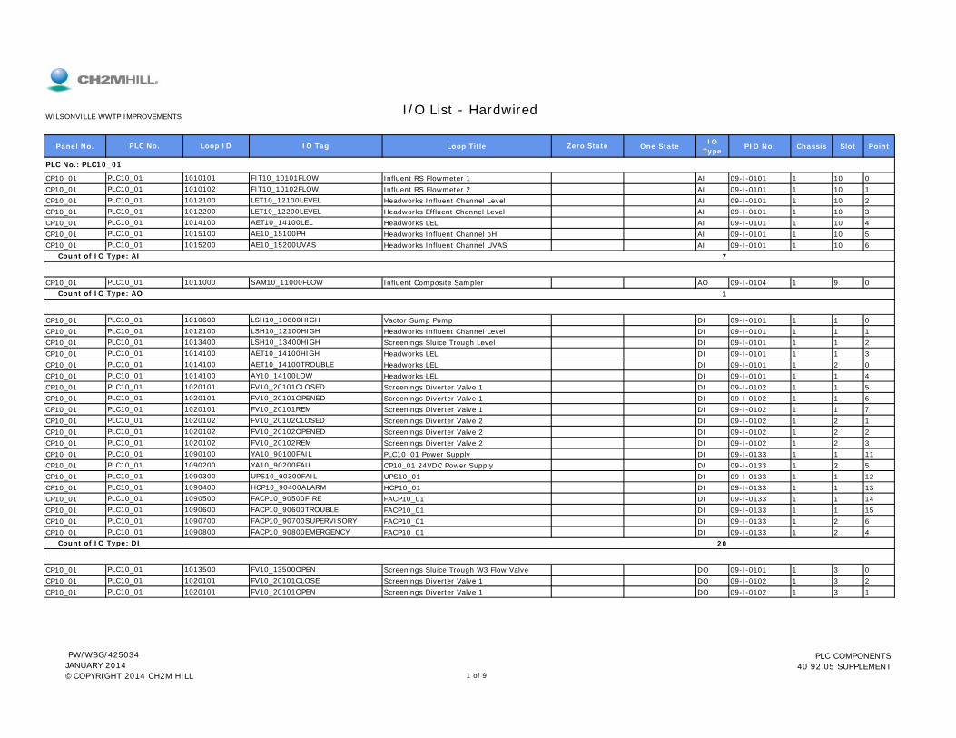
Panel No. Loop Title One State IO Type PID No. Chassis Slot Point
CP10_01 Influent RS Flowmeter 1 AI 09-I-0101 1 10 0CP10_01 Influent RS Flowmeter 2 AI 09-I-0101 1 10 1CP10_01 Headworks Influent Channel Level AI 09-I-0101 1 10 2CP10_01 Headworks Effluent Channel Level AI 09-I-0101 1 10 3CP10_01 Headworks LEL AI 09-I-0101 1 10 4CP10_01 Headworks Influent Channel pH AI 09-I-0101 1 10 5CP10_01 Headworks Influent Channel UVAS AI 09-I-0101 1 10 6
7
CP10_01 Influent Composite Sampler AO 09-I-0104 1 9 01
CP10_01 Vactor Sump Pump DI 09-I-0101 1 1 0CP10_01 Headworks Influent Channel Level DI 09-I-0101 1 1 1CP10_01 Screenings Sluice Trough Level DI 09-I-0101 1 1 2CP10_01 Headworks LEL DI 09-I-0101 1 1 3CP10_01 Headworks LEL DI 09-I-0101 1 2 0CP10_01 Headworks LEL DI 09-I-0101 1 1 4CP10_01 Screenings Diverter Valve 1 DI 09-I-0102 1 1 5CP10_01 Screenings Diverter Valve 1 DI 09-I-0102 1 1 6CP10 01 Screenings Diverter Valve 1 DI 09-I-0102 1 1 7PLC10 01 1020101 FV10 20101REM
PLC10_01 1020101 FV10_20101CLOSEDPLC10_01 1020101 FV10_20101OPENED
PLC10_01 1014100 AET10_14100TROUBLEPLC10_01 1014100 AY10_14100LOW
PLC10_01 1013400 LSH10_13400HIGHPLC10_01 1014100 AET10_14100HIGH
PLC10_01 1010600 LSH10_10600HIGHPLC10_01 1012100 LSH10_12100HIGH
PLC10_01 1011000 SAM10_11000FLOW Count of IO Type: AO
PLC10_01 1015200 AE10_15200UVAS Count of IO Type: AI
PLC10_01 1014100 AET10_14100LELPLC10_01 1015100 AE10_15100PH
PLC10_01 1012100 LET10_12100LEVELPLC10_01 1012200 LET10_12200LEVEL
PLC No.: PLC10_01
PLC10_01 1010101 FIT10_10101FLOWPLC10_01 1010102 FIT10_10102FLOW
I/O List - HardwiredWILSONVILLE WWTP IMPROVEMENTS
PLC No. Loop ID IO Tag Zero State
CP10_01 Screenings Diverter Valve 1 DI 09 I 0102 1 1 7CP10_01 Screenings Diverter Valve 2 DI 09-I-0102 1 2 1CP10_01 Screenings Diverter Valve 2 DI 09-I-0102 1 2 2CP10_01 Screenings Diverter Valve 2 DI 09-I-0102 1 2 3CP10_01 PLC10_01 Power Supply DI 09-I-0133 1 1 11CP10_01 CP10_01 24VDC Power Supply DI 09-I-0133 1 2 5CP10_01 UPS10_01 DI 09-I-0133 1 1 12CP10_01 HCP10_01 DI 09-I-0133 1 1 13CP10_01 FACP10_01 DI 09-I-0133 1 1 14CP10_01 FACP10_01 DI 09-I-0133 1 1 15CP10_01 FACP10_01 DI 09-I-0133 1 2 6CP10_01 FACP10_01 DI 09-I-0133 1 2 4
20
CP10_01 Screenings Sluice Trough W3 Flow Valve DO 09-I-0101 1 3 0CP10_01 Screenings Diverter Valve 1 DO 09-I-0102 1 3 2CP10_01 Screenings Diverter Valve 1 DO 09-I-0102 1 3 1
PLC10_01 1020101 FV10_20101CLOSEPLC10_01 1020101 FV10_20101OPEN
Count of IO Type: DI
PLC10_01 1013500 FV10_13500OPEN
PLC10_01 1090700 FACP10_90700SUPERVISORYPLC10_01 1090800 FACP10_90800EMERGENCY
PLC10_01 1090500 FACP10_90500FIREPLC10_01 1090600 FACP10_90600TROUBLE
PLC10_01 1090300 UPS10_90300FAILPLC10_01 1090400 HCP10_90400ALARM
PLC10_01 1090100 YA10_90100FAILPLC10_01 1090200 YA10_90200FAIL
PLC10_01 1020102 FV10_20102OPENEDPLC10_01 1020102 FV10_20102REM
PLC10_01 1020101 FV10_20101REMPLC10_01 1020102 FV10_20102CLOSED
PW/WBG/425034 JANUARY 2014 ©COPYRIGHT 2014 CH2M HILL 1 of 9
PLC COMPONENTS 40 92 05 SUPPLEMENT
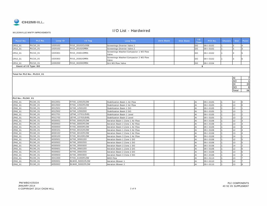
Panel No. Loop Title One State IO Type PID No. Chassis Slot Point
I/O List - HardwiredWILSONVILLE WWTP IMPROVEMENTS
PLC No. Loop ID IO Tag Zero State
CP10_01 Screenings Diverter Valve 2 DO 09-I-0102 1 3 4CP10_01 Screenings Diverter Valve 2 DO 09-I-0102 1 3 3
CP10_01 Screenings Washer/Compactor 1 W3 Flow Valve DO 09-I-0102 1 3 5
CP10_01 Screenings Washer/Compactor 2 W3 Flow Valve DO 09-I-0102 1 3 6
CP10_01 Grit W3 Flow Valve DO 09-I-01048
AI 7AO 1DI 20DO 8Total 36
CP40_01 Stabilization Basin 1 Air Flow AI 09-I-0105 1 12 0CP40_01 Stabilization Basin 2 Air Flow AI 09-I-0105 1 13 0CP40_01 Stabilization Basin 1 DO AI 09-I-0105 1 12 1CP40_01 Stabilization Basin 2 DO AI 09-I-0105 1 13 1CP40 01 Stabilization Basin 1 Level AI 09-I-0105 1 12 2PLC40 01 4012701 LET40 12701LEVEL
PLC40_01 4012501 AIT40_12501DOPLC40_01 4012502 AIT40_12502DO
PLC No.: PLC40_01
PLC40_01 4012001 FIT40_12001FLOWPLC40_01 4012002 FIT40_12002FLOW
Total for PLC No.: PLC10_01
PLC10_01 1030200 FV10_30200OPEN Count of IO Type: DO
PLC10_01 1020301 FV10_20301OPEN
PLC10_01 1020302 FV10_20302OPEN
PLC10_01 1020102 FV10_20102CLOSEPLC10_01 1020102 FV10_20102OPEN
CP40_01 Stabilization Basin 1 Level AI 09-I-0105 1 12 2CP40_01 Stabilization Basin 2 Level AI 09-I-0105 1 13 2CP40_01 Aeration Basin 1 Zone 1 Air Flow AI 09-I-0108 1 12 3CP40_01 Aeration Basin 2 Zone 1 Air Flow AI 09-I-0108 1 13 3CP40_01 Aeration Basin 3 Zone 1 Air Flow AI 09-I-0108 1 14 0CP40_01 Aeration Basin 1 Zone 2 Air Flow AI 09-I-0108 1 12 4CP40_01 Aeration Basin 2 Zone 2 Air Flow AI 09-I-0108 1 13 4CP40_01 Aeration Basin 3 Zone 2 Air Flow AI 09-I-0108 1 14 1CP40_01 Aeration Basin 1 Zone 1 DO AI 09-I-0108 1 12 5CP40_01 Aeration Basin 2 Zone 1 DO AI 09-I-0108 1 13 5CP40_01 Aeration Basin 3 Zone 1 DO AI 09-I-0108 1 14 2CP40_01 Aeration Basin 1 Zone 2 DO AI 09-I-0108 1 12 6CP40_01 Aeration Basin 2 Zone 2 DO AI 09-I-0108 1 13 6CP40_01 Aeration Basin 3 Zone 2 DO AI 09-I-0108 1 14 3CP40_01 WAS Flow AI 09-I-0113 1 13 7CP40_01 Aeration Blower 1 AI 09-I-0110 1 12 7CP40_01 Aeration Blower 2 AI 09-I-0110 1 13 8PLC40_01 4050002 BLW40_50002FLOW
PLC40_01 4041000 FIT40_41000FLOWPLC40_01 4050001 BLW40_50001FLOW
PLC40_01 4030602 AIT40_30602DOPLC40_01 4030603 AIT40_30603DO
PLC40_01 4030503 AIT40_30503DOPLC40_01 4030601 AIT40_30601DO
PLC40_01 4030501 AIT40_30501DOPLC40_01 4030502 AIT40_30502DO
PLC40_01 4030102 FIT40_30102FLOWPLC40_01 4030103 FIT40_30103FLOW
PLC40_01 4030003 FIT40_30003FLOWPLC40_01 4030101 FIT40_30101FLOW
PLC40_01 4030001 FIT40_30001FLOWPLC40_01 4030002 FIT40_30002FLOW
PLC40_01 4012701 LET40_12701LEVELPLC40_01 4012702 LET40_12702LEVEL
PW/WBG/425034 JANUARY 2014 ©COPYRIGHT 2014 CH2M HILL 2 of 9
PLC COMPONENTS 40 92 05 SUPPLEMENT

Panel No. Loop Title One State IO Type PID No. Chassis Slot Point
I/O List - HardwiredWILSONVILLE WWTP IMPROVEMENTS
PLC No. Loop ID IO Tag Zero State
CP40_01 Aeration Blower 3 AI 09-I-0110 1 14 4CP40_01 Aeration Blower Header Pressure AI 09-I-0110 1 12 8CP40_01 Existing Blowers Header Pressure AI 09-I-0110 1 13 9CP40_01 RAS Pump 1 Flow AI 09-I-0113 1 12 9CP40_01 RAS Pump 2 Flow AI 09-I-0113 1 13 10CP40_01 RAS Pump 3 Flow AI 09-I-0113 1 14 5CP40_01 RAS Pump 4 Flow AI 09-I-0113 1 12 10CP40_01 Secondary Effluent Wetwell Level AI 09-I-0115 1 12 11
29
CP40_01 Stabilization Basin 1 Air Flow AO 09-I-0105 1 10 0CP40_01 Stabilization Basin 2 Air Flow AO 09-I-0105 1 11 0CP40_01 Aeration Basin 1 Zone 1 Air Flow AO 09-I-0108 1 10 1CP40_01 Aeration Basin 2 Zone 1 Air Flow AO 09-I-0108 1 10 2CP40_01 Aeration Basin 3 Zone 1 Air Flow AO 09-I-0108 1 10 3CP40_01 Aeration Basin 1 Zone 2 Air Flow AO 09-I-0108 1 11 1CP40_01 Aeration Basin 2 Zone 2 Air Flow AO 09-I-0108 1 11 2CP40_01 Aeration Basin 3 Zone 2 Air Flow AO 09-I-0108 1 11 3CP40_01 WAS Flow AO 09-I-0113 1 10 4CP40_01 Aeration Blower 1 AO 09-I-0110 1 10 5CP40_01 Aeration Blower 2 AO 09-I-0110 1 11 4CP40_01 Aeration Blower 3 AO 09-I-0110 1 10 6
12 C t f IO T AO
PLC40_01 4050002 BLW40_50002FLOWSPPLC40_01 4050003 BLW40_50003FLOWSP
PLC40_01 4041000 FCV40_41000ZCPLC40_01 4050001 BLW40_50001FLOWSP
PLC40_01 4030102 FCV40_30102ZCPLC40_01 4030103 FCV40_30103ZC
PLC40_01 4030003 FCV40_30003ZCPLC40_01 4030101 FCV40_30101ZC
PLC40_01 4030001 FCV40_30001ZCPLC40_01 4030002 FCV40_30002ZC
PLC40_01 4012001 FCV40_12001ZCPLC40_01 4012002 FCV40_12002ZC
PLC40_01 5311000 LET53_11000LEVEL Count of IO Type: AI
PLC40_01 5000303 FIT50_00303FLOWPLC40_01 5000304 FIT50_00304FLOW
PLC40_01 5000301 FIT50_00301FLOWPLC40_01 5000302 FIT50_00302FLOW
PLC40_01 4050501 PIT40_50501PRESSUREPLC40_01 4050502 PIT40_50502PRESSURE
PLC40_01 4050003 BLW40_50003FLOW
12
CP40_01 Stabilization Basin 1 Air Flow DI 09-I-0105 1 1 0CP40_01 Stabilization Basin 2 Air Flow DI 09-I-0105 1 2 0CP40_01 Aeration Basin 1 Zone 1 Air Flow DI 09-I-0108 1 1 1CP40_01 Aeration Basin 2 Zone 1 Air Flow DI 09-I-0108 1 2 1CP40_01 Aeration Basin 3 Zone 1 Air Flow DI 09-I-0108 1 3 0CP40_01 Aeration Basin 1 Zone 2 Air Flow DI 09-I-0108 1 1 2CP40_01 Aeration Basin 2 Zone 2 Air Flow DI 09-I-0108 1 2 2CP40_01 Aeration Basin 3 Zone 2 Air Flow DI 09-I-0108 1 3 1CP40_01 WAS Flow DI 09-I-0113 1 1 3CP40_01 Aeration Blower 1 DI 09-I-0110 1 1 4CP40_01 Aeration Blower 1 DI 09-I-0110 1 1 5CP40_01 Aeration Blower 1 DI 09-I-0110 1 1 6CP40_01 Aeration Blower 2 DI 09-I-0110 1 2 3CP40_01 Aeration Blower 2 DI 09-I-0110 1 2 4CP40_01 Aeration Blower 2 DI 09-I-0110 1 2 5
PLC40_01 4050002 BLW40_50002FAILPLC40_01 4050002 BLW40_50002ON
PLC40_01 4050001 BLW40_50001ONPLC40_01 4050002 BLW40_50002AUTO
PLC40_01 4050001 BLW40_50001AUTOPLC40_01 4050001 BLW40_50001FAIL
PLC40_01 4030103 FCV40_30103REMPLC40_01 4041000 FCV40_41000REM
PLC40_01 4030101 FCV40_30101REMPLC40_01 4030102 FCV40_30102REM
PLC40_01 4030002 FCV40_30002REMPLC40_01 4030003 FCV40_30003REM
PLC40_01 4012002 FCV40_12002REMPLC40_01 4030001 FCV40_30001REM
Count of IO Type: AO
PLC40_01 4012001 FCV40_12001REM
PW/WBG/425034 JANUARY 2014 ©COPYRIGHT 2014 CH2M HILL 3 of 9
PLC COMPONENTS 40 92 05 SUPPLEMENT
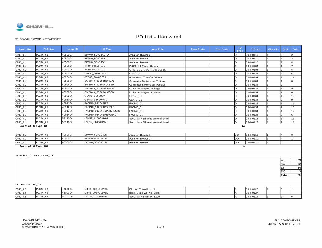
Panel No. Loop Title One State IO Type PID No. Chassis Slot Point
I/O List - HardwiredWILSONVILLE WWTP IMPROVEMENTS
PLC No. Loop ID IO Tag Zero State
CP40_01 Aeration Blower 3 DI 09-I-0110 1 3 2CP40_01 Aeration Blower 3 DI 09-I-0110 1 3 3CP40_01 Aeration Blower 3 DI 09-I-0110 1 3 4CP40_01 PLC40_01 Power Supply DI 09-I-0134 1 1 7CP40_01 CP40_01 24VDC Power Supply DI 09-I-0134 1 2 6CP40_01 UPS40_01 DI 09-I-0134 1 3 5CP40_01 Automated Transfer Switch DI 09-I-0134 1 1 14CP40_01 Generator Switchgear Voltage DI 09-I-0134 1 1 8CP40_01 Generator Switchgear Position DI 09-I-0134 1 2 7CP40_01 Utility Switchgear Voltage DI 09-I-0134 1 1 9CP40_01 Utility Switchgear Position DI 09-I-0134 1 2 8CP40_01 GEN40_01 DI 09-I-0134 1 1 10CP40_01 GEN40_01 DI 09-I-0134 1 2 9CP40_01 FACP40_01 DI 09-I-0134 1 1 11CP40_01 FACP40_01 DI 09-I-0134 1 2 10CP40_01 FACP40_01 DI 09-I-0134 1 1 12CP40_01 FACP40_01 DI 09-I-0134 1 3 6CP40_01 Secondary Effluent Wetwell Level DI 09-I-0115 1 1 13CP40_01 Secondary Effluent Wetwell Level DI 09-I-0115 1 2 11
34
CP40_01 Aeration Blower 1 DO 09-I-0110 1 4 0CP40 01 A ti Bl 2 DO 09 I 0110 1 4 1
PLC40_01 4050001 BLW40_50001RUNPLC40 01 4050002 BLW40 50002RUN
PLC40_01 5311000 LSL53_11000LOW Count of IO Type: DI
PLC40_01 4091400 FACP40_91400EMERGENCYPLC40_01 5311000 LSH53_11000HIGH
PLC40_01 4091200 FACP40_91200TROUBLEPLC40_01 4091300 FACP40_91300SUPERVISORY
PLC40_01 4091000 GEN40_91000FAILPLC40_01 4091100 FACP40_91100FIRE
PLC40_01 4090800 SWBD40_90800CLOSEDPLC40_01 4090900 GEN40_90900ON
PLC40_01 4090600 SWBD40_90600CLOSEDPLC40_01 4090700 SWBD40_90700NORMAL
PLC40_01 4090400 ATS40_90400FAILPLC40_01 4090500 SWBD40_90500NORMAL
PLC40_01 4090200 YA40_90200FAILPLC40_01 4090300 UPS40_90300FAIL
PLC40_01 4050003 BLW40_50003ONPLC40_01 4090100 YA40_90100FAIL
PLC40_01 4050003 BLW40_50003AUTOPLC40_01 4050003 BLW40_50003FAIL
CP40_01 Aeration Blower 2 DO 09-I-0110 1 4 1CP40_01 Aeration Blower 3 DO 09-I-0110 1 4 2
3
AI 29AO 12DI 34DO 3Total 78
CP40_02 Filtrate Wetwell Level AI 09-I-0127 1 9 1CP40_02 Basin Drain Wetwell Level AI 09-I-0127CP40_02 Secondary Scum Pit Level AI 09-I-0114 1 9 6PLC40_02 5020200 LET50_20200LEVEL
PLC No.: PLC40_02
PLC40_02 4500200 LIT45_00200LEVELPLC40_02 4500300 LIT45_00300LEVEL
Total for PLC No.: PLC40_01
PLC40_01 4050003 BLW40_50003RUN Count of IO Type: DO
PLC40_01 4050002 BLW40_50002RUN
PW/WBG/425034 JANUARY 2014 ©COPYRIGHT 2014 CH2M HILL 4 of 9
PLC COMPONENTS 40 92 05 SUPPLEMENT
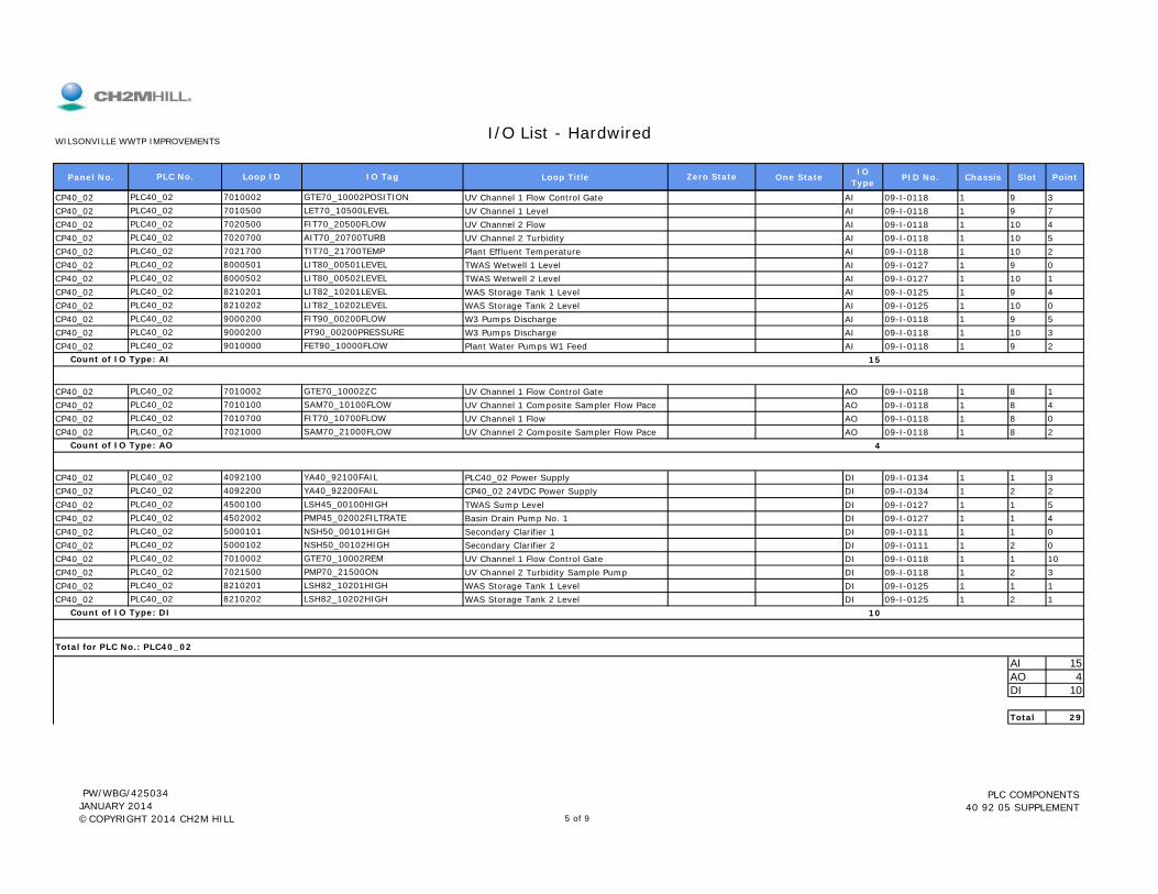
Panel No. Loop Title One State IO Type PID No. Chassis Slot Point
I/O List - HardwiredWILSONVILLE WWTP IMPROVEMENTS
PLC No. Loop ID IO Tag Zero State
CP40_02 UV Channel 1 Flow Control Gate AI 09-I-0118 1 9 3CP40_02 UV Channel 1 Level AI 09-I-0118 1 9 7CP40_02 UV Channel 2 Flow AI 09-I-0118 1 10 4CP40_02 UV Channel 2 Turbidity AI 09-I-0118 1 10 5CP40_02 Plant Effluent Temperature AI 09-I-0118 1 10 2CP40_02 TWAS Wetwell 1 Level AI 09-I-0127 1 9 0CP40_02 TWAS Wetwell 2 Level AI 09-I-0127 1 10 1CP40_02 WAS Storage Tank 1 Level AI 09-I-0125 1 9 4CP40_02 WAS Storage Tank 2 Level AI 09-I-0125 1 10 0CP40_02 W3 Pumps Discharge AI 09-I-0118 1 9 5CP40_02 W3 Pumps Discharge AI 09-I-0118 1 10 3CP40_02 Plant Water Pumps W1 Feed AI 09-I-0118 1 9 2
15
CP40_02 UV Channel 1 Flow Control Gate AO 09-I-0118 1 8 1CP40_02 UV Channel 1 Composite Sampler Flow Pace AO 09-I-0118 1 8 4CP40_02 UV Channel 1 Flow AO 09-I-0118 1 8 0CP40_02 UV Channel 2 Composite Sampler Flow Pace AO 09-I-0118 1 8 2
4
CP40_02 PLC40_02 Power Supply DI 09-I-0134 1 1 3CP40_02 CP40_02 24VDC Power Supply DI 09-I-0134 1 2 2PLC40_02 4092200 YA40_92200FAIL
Count of IO Type: AO
PLC40_02 4092100 YA40_92100FAIL
PLC40_02 7010700 FIT70_10700FLOWPLC40_02 7021000 SAM70_21000FLOW
PLC40_02 7010002 GTE70_10002ZCPLC40_02 7010100 SAM70_10100FLOW
PLC40_02 9010000 FET90_10000FLOW Count of IO Type: AI
PLC40_02 9000200 FIT90_00200FLOWPLC40_02 9000200 PT90_00200PRESSURE
PLC40_02 8210201 LIT82_10201LEVELPLC40_02 8210202 LIT82_10202LEVEL
PLC40_02 8000501 LIT80_00501LEVELPLC40_02 8000502 LIT80_00502LEVEL
PLC40_02 7020700 AIT70_20700TURBPLC40_02 7021700 TIT70_21700TEMP
PLC40_02 7010500 LET70_10500LEVELPLC40_02 7020500 FIT70_20500FLOW
PLC40_02 7010002 GTE70_10002POSITION
CP40_02 TWAS Sump Level DI 09-I-0127 1 1 5CP40_02 Basin Drain Pump No. 1 DI 09-I-0127 1 1 4CP40_02 Secondary Clarifier 1 DI 09-I-0111 1 1 0CP40_02 Secondary Clarifier 2 DI 09-I-0111 1 2 0CP40_02 UV Channel 1 Flow Control Gate DI 09-I-0118 1 1 10CP40_02 UV Channel 2 Turbidity Sample Pump DI 09-I-0118 1 2 3CP40_02 WAS Storage Tank 1 Level DI 09-I-0125 1 1 1CP40_02 WAS Storage Tank 2 Level DI 09-I-0125 1 2 1
10
AI 15AO 4DI 10
Total 29
Total for PLC No.: PLC40_02
PLC40_02 8210202 LSH82_10202HIGH Count of IO Type: DI
PLC40_02 7021500 PMP70_21500ONPLC40_02 8210201 LSH82_10201HIGH
PLC40_02 5000102 NSH50_00102HIGHPLC40_02 7010002 GTE70_10002REM
PLC40_02 4502002 PMP45_02002FILTRATEPLC40_02 5000101 NSH50_00101HIGH
PLC40_02 4500100 LSH45_00100HIGH
PW/WBG/425034 JANUARY 2014 ©COPYRIGHT 2014 CH2M HILL 5 of 9
PLC COMPONENTS 40 92 05 SUPPLEMENT

Panel No. Loop Title One State IO Type PID No. Chassis Slot Point
I/O List - HardwiredWILSONVILLE WWTP IMPROVEMENTS
PLC No. Loop ID IO Tag Zero State
LCP80_04 WAS Flow to GBTs AI 09-I-0126 1 7 1LCP80_04 Gravity Belt 1 Drive AI 09-I-0126A 1 7 0LCP80_04 Gravity Belt 2 Drive AI 09-I-0126A 1 7 2
3
LCP80_04 Filtrate Wetwell Level DI 09-I-0127 1 3 12LCP80_04 Gravity Belt Thickener System Alarm DI 09-I-0126A 1 1 0LCP80_04 Gravity Belt Thickener System Alarm DI 09-I-0126A 1 1 1LCP80_04 Gravity Belt Thickener 1 DI 09-I-0126A 1 1 2LCP80_04 Gravity Belt Thickener 1 DI 09-I-0126A 1 1 6LCP80_04 Gravity Belt Thickener 1 DI 09-I-0126A 1 1 5LCP80_04 Gravity Belt Thickener 2 DI 09-I-0126A 1 2 2LCP80_04 Gravity Belt Thickener 2 DI 09-I-0126A 1 2 6LCP80_04 Gravity Belt Thickener 2 DI 09-I-0126A 1 2 5LCP80_04 Gravity Belt 1 Drive DI 09-I-0126A 1 1 4LCP80_04 Gravity Belt 1 Drive DI 09-I-0126A 1 1 3LCP80_04 Gravity Belt 1 Drive DI 09-I-0126A 1 1 11LCP80_04 Gravity Belt 1 Drive DI 09-I-0126A 1 1 14LCP80_04 Gravity Belt 2 Drive DI 09-I-0126A 1 2 4LCP80 04 Gravity Belt 2 Drive DI 09-I-0126A 1 2 3PLC40 03 8000412 GBT80 00412LOPRESS
PLC40_03 8000411 GBT80_00411OVLDPLC40_03 8000412 GBT80_00412BROKE
PLC40_03 8000411 GBT80_00411MISALIGNPLC40_03 8000411 GBT80_00411ON
PLC40_03 8000402 GBT80_00402LOPRESSPLC40_03 8000411 GBT80_00411BROKE
PLC40_03 8000402 GBT80_00402ESTOPPLC40_03 8000402 GBT80_00402HILVL
PLC40_03 8000401 GBT80_00401HILVLPLC40_03 8000401 GBT80_00401LOPRESS
PLC40_03 8000400 GBT80_00400SILENCEPLC40_03 8000401 GBT80_00401ESTOP
PLC40_03 4500200 LSH45_00200HIGHPLC40_03 8000400 GBT80_00400RESET
PLC40_03 8000412 GBT80_00412SPEED Count of IO Type: AI
PLC No.: PLC40_03
PLC40_03 5000500 FIT50_00500FLOWPLC40_03 8000411 GBT80_00411SPEED
LCP80_04 Gravity Belt 2 Drive DI 09 I 0126A 1 2 3LCP80_04 Gravity Belt 2 Drive DI 09-I-0126A 1 2 11LCP80_04 Gravity Belt 2 Drive DI 09-I-0126A 1 2 14LCP80_04 Gravity Belt 1 Hydraulic Pump DI 09-I-0126A 1 1 7LCP80_04 Gravity Belt 1 Hydraulic Pump DI 09-I-0126A 1 1 10LCP80_04 Gravity Belt 1 Hydraulic Pump DI 09-I-0126A 1 1 8LCP80_04 Gravity Belt 2 Hydraulic Pump DI 09-I-0126A 1 2 7LCP80_04 Gravity Belt 2 Hydraulic Pump DI 09-I-0126A 1 2 10LCP80_04 Gravity Belt 2 Hydraulic Pump DI 09-I-0126A 1 2 8LCP80_04 TWAS Wetwell 1 Level DI 09-I-0127 1 3 11LCP80_04 TWAS Wetwell 2 Level DI 09-I-0127 1 3 10LCP80_04 Polymer Blend Unit 1 DI 09-I-0126 1 3 8LCP80_04 Polymer Blend Unit 1 DI 09-I-0126 1 1 13LCP80_04 Polymer Blend Unit 2 DI 09-I-0126 1 3 9LCP80_04 Polymer Blend Unit 2 DI 09-I-0126 1 2 13
29PLC40_03 8100002 BLD81_00002ON
Count of IO Type: DI
PLC40_03 8100001 BLD81_00001ONPLC40_03 8100002 BLD81_00002LO
PLC40_03 8000502 LSH80_00502HIGHPLC40_03 8100001 BLD81_00001LO
PLC40_03 8000422 GBT80_00422OVLDPLC40_03 8000501 LSH80_00501HIGH
PLC40_03 8000422 GBT80_00422LOPRESSPLC40_03 8000422 GBT80_00422ON
PLC40_03 8000421 GBT80_00421ONPLC40_03 8000421 GBT80_00421OVLD
PLC40_03 8000412 GBT80_00412OVLDPLC40_03 8000421 GBT80_00421LOPRESS
PLC40_03 8000412 GBT80_00412LOPRESSPLC40_03 8000412 GBT80_00412ON
PW/WBG/425034 JANUARY 2014 ©COPYRIGHT 2014 CH2M HILL 6 of 9
PLC COMPONENTS 40 92 05 SUPPLEMENT

Panel No. Loop Title One State IO Type PID No. Chassis Slot Point
I/O List - HardwiredWILSONVILLE WWTP IMPROVEMENTS
PLC No. Loop ID IO Tag Zero State
LCP80_04 Gravity Belt Thickener System Alarm DO 09-I-0126A 1 9 0LCP80_04 Gravity Belt Thickener System Alarm DO 09-I-0126A 1 9 1LCP80_04 Gravity Belt Thickener 1 DO 09-I-0126A 1 9 2LCP80_04 Gravity Belt Thickener 2 DO 09-I-0126A 1 9 3LCP80_04 Gravity Belt 1 Drive DO 09-I-0126A 1 5 2LCP80_04 Gravity Belt 2 Drive DO 09-I-0126A 1 5 6LCP80_04 Gravity Belt 1 Hydraulic Pump DO 09-I-0126A 1 5 1LCP80_04 Gravity Belt 2 Hydraulic Pump DO 09-I-0126A 1 5 5LCP80_04 Polymer Blend Unit 1 DO 09-I-0126 1 5 3LCP80_04 Polymer Blend Unit 2 DO 09-I-0126 1 5 7
10
AI 3DI 29DO 10
Total 42
CP78_01 Centrifuge 1 TWAS Flow AI 09-I-0129 1 9 4C 8 0 830002 8 30002 O
PLC No.: PLC78_01
PLC78_01 7830001 FIT78_30001FLOW
Count of IO Type: DO
Total for PLC No.: PLC40_03
PLC40_03 8100001 BLD81_00001RUNPLC40_03 8100002 BLD81_00002RUN
PLC40_03 8000421 GBT80_00421RUNPLC40_03 8000422 GBT80_00422RUN
PLC40_03 8000411 GBT80_00411RUNPLC40_03 8000412 GBT80_00412RUN
PLC40_03 8000401 GBT80_00401ONPLC40_03 8000402 GBT80_00402ON
PLC40_03 8000400 GBT80_00400HORNPLC40_03 8000400 GBT80_00400SILENCED
CP78_01 Centrifuge 2 TWAS Flow AI 09-I-0129 1 10 3CP78_01 Weather Station Temperature AI 09-I-0133 1 9 6CP78_01 Weather Station Wind Speed AI 09-I-0133 1 9 7CP78_01 Weather Station Humidity AI 09-I-0133 1 9 8CP78_01 Weather Station Wind Direction AI 09-I-0133 1 10 4CP78_01 Weather Station Rain Gauge AI 09-I-0133 1 10 5CP78_01 Weather Station Atmospheric Pressure AI 09-I-0133 1 10 6CP78_01 TWAS Storage Tank 1 Level AI 09-I-0128 1 9 5CP78_01 TWAS Storage Tank 2 Level AI 09-I-0128 1 10 2CP78_01 Sludge Storage Odorous Air LEL AI 09-I-0128 1 9 1CP78_01 Odor Control Fan 1 Differential Pressure AI 09-I-0120 1 9 0CP78_01 Odor Control Fan 2 Differential Pressure AI 09-I-0120 1 10 0CP78_01 Odor Control Low Range H2S AI 09-I-0121 1 10 1CP78_01 Odor Control High Range H2S AI 09-I-0121 1 9 2CP78_01 Plant Drain Flow AI 09-I-0123 1 9 3
16PLC78_01 9611000 FET96_11000FLOW
Count of IO Type: AI
PLC78_01 9122001 AET91_22001H2SPLC78_01 9122002 AET91_22002H2S
PLC78_01 9110601 PDT91_10601PDIFFPLC78_01 9110602 PDT91_10602PDIFF
PLC78_01 8220202 LIT82_20202LEVELPLC78_01 9110100 AET91_10100LEL
PLC78_01 7850006 PT78_50006PRESSUREPLC78_01 8220201 LIT82_20201LEVEL
PLC78_01 7850004 ZT78_50004DIRECTIONPLC78_01 7850005 QT78_50005RAIN
PLC78_01 7850002 ST78_50002SPEEDPLC78_01 7850003 AT78_50003RH
PLC78_01 7830002 FIT78_30002FLOWPLC78_01 7850001 TT78_50001TEMP
PW/WBG/425034 JANUARY 2014 ©COPYRIGHT 2014 CH2M HILL 7 of 9
PLC COMPONENTS 40 92 05 SUPPLEMENT
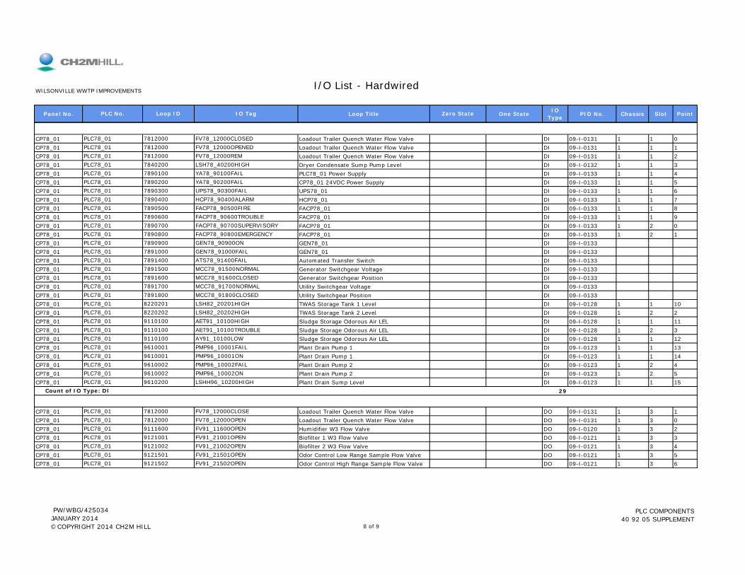
Panel No. Loop Title One State IO Type PID No. Chassis Slot Point
I/O List - HardwiredWILSONVILLE WWTP IMPROVEMENTS
PLC No. Loop ID IO Tag Zero State
CP78_01 Loadout Trailer Quench Water Flow Valve DI 09-I-0131 1 1 0CP78_01 Loadout Trailer Quench Water Flow Valve DI 09-I-0131 1 1 1CP78_01 Loadout Trailer Quench Water Flow Valve DI 09-I-0131 1 1 2CP78_01 Dryer Condensate Sump Pump Level DI 09-I-0132 1 1 3CP78_01 PLC78_01 Power Supply DI 09-I-0133 1 1 4CP78_01 CP78_01 24VDC Power Supply DI 09-I-0133 1 1 5CP78_01 UPS78_01 DI 09-I-0133 1 1 6CP78_01 HCP78_01 DI 09-I-0133 1 1 7CP78_01 FACP78_01 DI 09-I-0133 1 1 8CP78_01 FACP78_01 DI 09-I-0133 1 1 9CP78_01 FACP78_01 DI 09-I-0133 1 2 0CP78_01 FACP78_01 DI 09-I-0133 1 2 1CP78_01 GEN78_01 DI 09-I-0133CP78_01 GEN78_01 DI 09-I-0133CP78_01 Automated Transfer Switch DI 09-I-0133CP78_01 Generator Switchgear Voltage DI 09-I-0133CP78_01 Generator Switchgear Position DI 09-I-0133CP78_01 Utility Switchgear Voltage DI 09-I-0133CP78_01 Utility Switchgear Position DI 09-I-0133CP78_01 TWAS Storage Tank 1 Level DI 09-I-0128 1 1 10CP78_01 TWAS Storage Tank 2 Level DI 09-I-0128 1 2 2CP78 01 Sl d St Od Ai LEL DI 09 I 0128 1 1 11
PLC78_01 8220202 LSH82_20202HIGHPLC78 01 9110100 AET91 10100HIGH
PLC78_01 7891800 MCC78_91800CLOSEDPLC78_01 8220201 LSH82_20201HIGH
PLC78_01 7891600 MCC78_91600CLOSEDPLC78_01 7891700 MCC78_91700NORMAL
PLC78_01 7891400 ATS78_91400FAILPLC78_01 7891500 MCC78_91500NORMAL
PLC78_01 7890900 GEN78_90900ONPLC78_01 7891000 GEN78_91000FAIL
PLC78_01 7890700 FACP78_90700SUPERVISORYPLC78_01 7890800 FACP78_90800EMERGENCY
PLC78_01 7890500 FACP78_90500FIREPLC78_01 7890600 FACP78_90600TROUBLE
PLC78_01 7890300 UPS78_90300FAILPLC78_01 7890400 HCP78_90400ALARM
PLC78_01 7890100 YA78_90100FAILPLC78_01 7890200 YA78_90200FAIL
PLC78_01 7812000 FV78_12000REMPLC78_01 7840200 LSH78_40200HIGH
PLC78_01 7812000 FV78_12000CLOSEDPLC78_01 7812000 FV78_12000OPENED
CP78_01 Sludge Storage Odorous Air LEL DI 09-I-0128 1 1 11CP78_01 Sludge Storage Odorous Air LEL DI 09-I-0128 1 2 3CP78_01 Sludge Storage Odorous Air LEL DI 09-I-0128 1 1 12CP78_01 Plant Drain Pump 1 DI 09-I-0123 1 1 13CP78_01 Plant Drain Pump 1 DI 09-I-0123 1 1 14CP78_01 Plant Drain Pump 2 DI 09-I-0123 1 2 4CP78_01 Plant Drain Pump 2 DI 09-I-0123 1 2 5CP78_01 Plant Drain Sump Level DI 09-I-0123 1 1 15
29
CP78_01 Loadout Trailer Quench Water Flow Valve DO 09-I-0131 1 3 1CP78_01 Loadout Trailer Quench Water Flow Valve DO 09-I-0131 1 3 0CP78_01 Humidifier W3 Flow Valve DO 09-I-0120 1 3 2CP78_01 Biofilter 1 W3 Flow Valve DO 09-I-0121 1 3 3CP78_01 Biofilter 2 W3 Flow Valve DO 09-I-0121 1 3 4CP78_01 Odor Control Low Range Sample Flow Valve DO 09-I-0121 1 3 5CP78_01 Odor Control High Range Sample Flow Valve DO 09-I-0121 1 3 6PLC78_01 9121502 FV91_21502OPEN
PLC78_01 9121002 FV91_21002OPENPLC78_01 9121501 FV91_21501OPEN
PLC78_01 9111600 FV91_11600OPENPLC78_01 9121001 FV91_21001OPEN
PLC78_01 7812000 FV78_12000CLOSEPLC78_01 7812000 FV78_12000OPEN
PLC78_01 9610200 LSHH96_10200HIGH Count of IO Type: DI
PLC78_01 9610002 PMP96_10002FAILPLC78_01 9610002 PMP96_10002ON
PLC78_01 9610001 PMP96_10001FAILPLC78_01 9610001 PMP96_10001ON
PLC78_01 9110100 AET91_10100TROUBLEPLC78_01 9110100 AY91_10100LOW
PLC78_01 9110100 AET91_10100HIGH
PW/WBG/425034 JANUARY 2014 ©COPYRIGHT 2014 CH2M HILL 8 of 9
PLC COMPONENTS 40 92 05 SUPPLEMENT
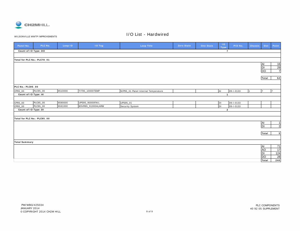
Panel No. Loop Title One State IO Type PID No. Chassis Slot Point
I/O List - HardwiredWILSONVILLE WWTP IMPROVEMENTS
PLC No. Loop ID IO Tag Zero State
7
AI 16DI 29DO 7
Total 52
CP95_00 NIP95_01 Panel Internal Temperature AI 09-I-0133 1 7 71
CP95_00 UPS95_01 DI 09-I-0133CP95_00 Security System DI 09-I-0133
2
AI 1DI 2
Count of IO Type: DI
Total for PLC No.: PLC95_00
PLC95_00 9590000 UPS95_90000FAILPLC95_00 9591000 BSVR95_91000ALARM
PLC No.: PLC95_00
PLC95_00 9510000 TIT95_10000TEMP Count of IO Type: AI
Total for PLC No.: PLC78_01
Count of IO Type: DO
Total 3
AI 71AO 17DI 124DO 28Total 240
Total Summary
PW/WBG/425034 JANUARY 2014 ©COPYRIGHT 2014 CH2M HILL 9 of 9
PLC COMPONENTS 40 92 05 SUPPLEMENT

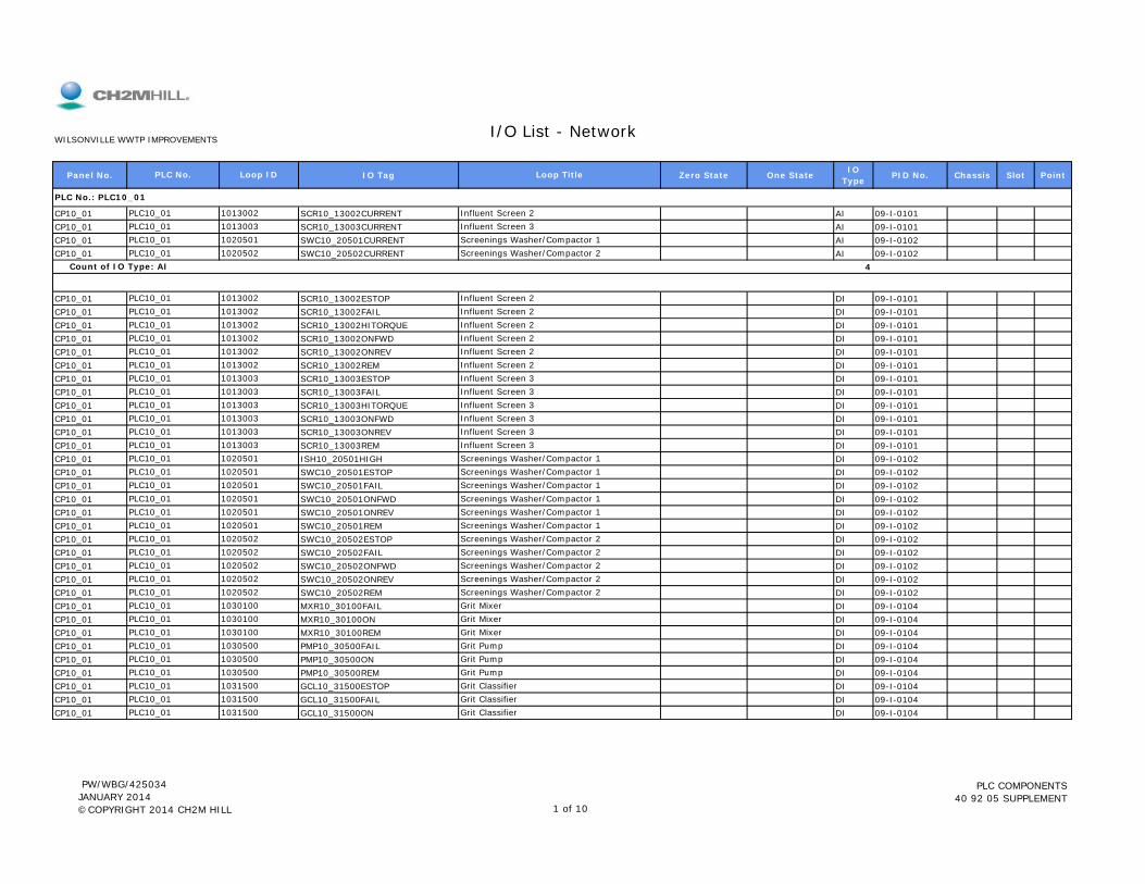
Panel No. IO Tag Zero State One State IO Type PID No. Chassis Slot Point
CP10_01 SCR10_13002CURRENT AI 09-I-0101CP10_01 SCR10_13003CURRENT AI 09-I-0101CP10_01 SWC10_20501CURRENT AI 09-I-0102CP10_01 SWC10_20502CURRENT AI 09-I-0102
4
CP10_01 SCR10_13002ESTOP DI 09-I-0101CP10_01 SCR10_13002FAIL DI 09-I-0101CP10_01 SCR10_13002HITORQUE DI 09-I-0101CP10_01 SCR10_13002ONFWD DI 09-I-0101CP10_01 SCR10_13002ONREV DI 09-I-0101CP10_01 SCR10_13002REM DI 09-I-0101CP10_01 SCR10_13003ESTOP DI 09-I-0101CP10_01 SCR10_13003FAIL DI 09-I-0101CP10_01 SCR10_13003HITORQUE DI 09-I-0101CP10_01 SCR10_13003ONFWD DI 09-I-0101CP10_01 SCR10_13003ONREV DI 09-I-0101CP10_01 SCR10_13003REM DI 09-I-0101CP10_01 ISH10_20501HIGH DI 09-I-0102CP10_01 SWC10_20501ESTOP DI 09-I-0102CP10_01 SWC10_20501FAIL DI 09-I-0102
PLC10_01 1020501 Screenings Washer/Compactor 1PLC10_01 1020501 Screenings Washer/Compactor 1
PLC10_01 1013003 Influent Screen 3PLC10_01 1020501 Screenings Washer/Compactor 1
PLC10_01 1013003 Influent Screen 3PLC10_01 1013003 Influent Screen 3
PLC10_01 1013003 Influent Screen 3PLC10_01 1013003 Influent Screen 3
PLC10_01 1013002 Influent Screen 2PLC10_01 1013003 Influent Screen 3
PLC10_01 1013002 Influent Screen 2PLC10_01 1013002 Influent Screen 2
PLC10_01 1013002 Influent Screen 2PLC10_01 1013002 Influent Screen 2
Count of IO Type: AI
PLC10_01 1013002 Influent Screen 2
PLC10_01 1020501 Screenings Washer/Compactor 1PLC10_01 1020502 Screenings Washer/Compactor 2
PLC No.: PLC10_01
PLC10_01 1013002 Influent Screen 2PLC10_01 1013003 Influent Screen 3
I/O List - NetworkWILSONVILLE WWTP IMPROVEMENTS
PLC No. Loop ID Loop Title
CP10_01 SWC10_20501ONFWD DI 09-I-0102CP10_01 SWC10_20501ONREV DI 09-I-0102CP10_01 SWC10_20501REM DI 09-I-0102CP10_01 SWC10_20502ESTOP DI 09-I-0102CP10_01 SWC10_20502FAIL DI 09-I-0102CP10_01 SWC10_20502ONFWD DI 09-I-0102CP10_01 SWC10_20502ONREV DI 09-I-0102CP10_01 SWC10_20502REM DI 09-I-0102CP10_01 MXR10_30100FAIL DI 09-I-0104CP10_01 MXR10_30100ON DI 09-I-0104CP10_01 MXR10_30100REM DI 09-I-0104CP10_01 PMP10_30500FAIL DI 09-I-0104CP10_01 PMP10_30500ON DI 09-I-0104CP10_01 PMP10_30500REM DI 09-I-0104CP10_01 GCL10_31500ESTOP DI 09-I-0104CP10_01 GCL10_31500FAIL DI 09-I-0104CP10_01 GCL10_31500ON DI 09-I-0104PLC10_01 1031500 Grit Classifier
PLC10_01 1031500 Grit ClassifierPLC10_01 1031500 Grit Classifier
PLC10_01 1030500 Grit PumpPLC10_01 1030500 Grit Pump
PLC10_01 1030100 Grit MixerPLC10_01 1030500 Grit Pump
PLC10_01 1030100 Grit MixerPLC10_01 1030100 Grit Mixer
PLC10_01 1020502 Screenings Washer/Compactor 2PLC10_01 1020502 Screenings Washer/Compactor 2
PLC10_01 1020502 Screenings Washer/Compactor 2PLC10_01 1020502 Screenings Washer/Compactor 2
PLC10_01 1020501 Screenings Washer/Compactor 1PLC10_01 1020502 Screenings Washer/Compactor 2
PLC10_01 1020501 Screenings Washer/Compactor 1PLC10_01 1020501 Screenings Washer/Compactor 1
PW/WBG/425034 JANUARY 2014 ©COPYRIGHT 2014 CH2M HILL 1 of 10
PLC COMPONENTS 40 92 05 SUPPLEMENT

Panel No. IO Tag Zero State One State IO Type PID No. Chassis Slot Point
I/O List - NetworkWILSONVILLE WWTP IMPROVEMENTS
PLC No. Loop ID Loop Title
CP10_01 GCL10_31500REM DI 09-I-010433
CP10_01 SCR10_13002FWD DO 09-I-0101CP10_01 SCR10_13002REV DO 09-I-0101CP10_01 SCR10_13003FWD DO 09-I-0101CP10_01 SCR10_13003REV DO 09-I-0101CP10_01 SWC10_20501FWD DO 09-I-0102CP10_01 SWC10_20501REV DO 09-I-0102CP10_01 SWC10_20502FWD DO 09-I-0102CP10_01 SWC10_20502REV DO 09-I-0102CP10_01 MXR10_30100RUN DO 09-I-0104CP10_01 PMP10_30500RUN DO 09-I-0104CP10_01 GCL10_31500RUN DO 09-I-0104
11
AI 4DI 33DO 11
Total 48
Count of IO Type: DO
Total for PLC No.: PLC10_01
PLC10_01 1030500 Grit PumpPLC10_01 1031500 Grit Classifier
PLC10_01 1020502 Screenings Washer/Compactor 2PLC10_01 1030100 Grit Mixer
PLC10_01 1020501 Screenings Washer/Compactor 1PLC10_01 1020502 Screenings Washer/Compactor 2
PLC10_01 1013003 Influent Screen 3PLC10_01 1020501 Screenings Washer/Compactor 1
PLC10_01 1013002 Influent Screen 2PLC10_01 1013003 Influent Screen 3
Count of IO Type: DI
PLC10_01 1013002 Influent Screen 2
PLC10_01 1031500 Grit Classifier
Total 48
CP40_01 PMP50_03001SPEED AI 09-I-0113CP40_01 PMP50_03002SPEED AI 09-I-0113CP40_01 PMP50_03003SPEED AI 09-I-0113CP40_01 PMP50_03004SPEED AI 09-I-0113CP40_01 PMP53_10001SPEED AI 09-I-0115CP40_01 PMP53_10002SPEED AI 09-I-0115CP40_01 PMP53_10003SPEED AI 09-I-0115
7
CP40_01 PMP50_03001SC AO 09-I-0113CP40_01 PMP50_03002SC AO 09-I-0113CP40_01 PMP50_03003SC AO 09-I-0113CP40_01 PMP50_03004SC AO 09-I-0113PLC40_01 5003004 RAS Pump 4
PLC40_01 5003002 RAS Pump 2PLC40_01 5003003 RAS Pump 3
Count of IO Type: AI
PLC40_01 5003001 RAS Pump 1
PLC40_01 5310002 Secondary Effluent Pump 2PLC40_01 5310003 Secondary Effluent Pump 3
PLC40_01 5003004 RAS Pump 4PLC40_01 5310001 Secondary Effluent Pump 1
PLC40_01 5003002 RAS Pump 2PLC40_01 5003003 RAS Pump 3
PLC No.: PLC40_01
PLC40_01 5003001 RAS Pump 1
PW/WBG/425034 JANUARY 2014 ©COPYRIGHT 2014 CH2M HILL 2 of 10
PLC COMPONENTS 40 92 05 SUPPLEMENT

Panel No. IO Tag Zero State One State IO Type PID No. Chassis Slot Point
I/O List - NetworkWILSONVILLE WWTP IMPROVEMENTS
PLC No. Loop ID Loop Title
CP40_01 PMP53_10001SC AO 09-I-0115CP40_01 PMP53_10002SC AO 09-I-0115CP40_01 PMP53_10003SC AO 09-I-0115
7
CP40_01 ISL40_20001LOW DI 09-I-0107CP40_01 MXR40_20001FAIL DI 09-I-0107CP40_01 MXR40_20001ON DI 09-I-0107CP40_01 ISL40_20002LOW DI 09-I-0107CP40_01 MXR40_20002FAIL DI 09-I-0107CP40_01 MXR40_20002ON DI 09-I-0107CP40_01 ISL40_20003LOW DI 09-I-0107CP40_01 MXR40_20003FAIL DI 09-I-0107CP40_01 MXR40_20003ON DI 09-I-0107CP40_01 ISL40_20004LOW DI 09-I-0107CP40_01 MXR40_20004FAIL DI 09-I-0107CP40_01 MXR40_20004ON DI 09-I-0107CP40_01 ISL40_20005LOW DI 09-I-0107CP40_01 MXR40_20005FAIL DI 09-I-0107CP40_01 MXR40_20005ON DI 09-I-0107CP40_01 ISL40_20006LOW DI 09-I-0107CP40_01 MXR40_20006FAIL DI 09-I-0107CP40 01 MXR40 20006ON DI 09 I 0107PLC40 01 4020006 A ti B i 3 A bi Mi 6
PLC40_01 4020006 Aeration Basin 3 Anaerobic Mixer 6PLC40_01 4020006 Aeration Basin 3 Anaerobic Mixer 6
PLC40_01 4020005 Aeration Basin 3 Anaerobic Mixer 5PLC40_01 4020005 Aeration Basin 3 Anaerobic Mixer 5
PLC40_01 4020004 Aeration Basin 2 Anaerobic Mixer 4PLC40_01 4020005 Aeration Basin 3 Anaerobic Mixer 5
PLC40_01 4020004 Aeration Basin 2 Anaerobic Mixer 4PLC40_01 4020004 Aeration Basin 2 Anaerobic Mixer 4
PLC40_01 4020003 Aeration Basin 2 Anaerobic Mixer 3PLC40_01 4020003 Aeration Basin 2 Anaerobic Mixer 3
PLC40_01 4020002 Aeration Basin 1 Anaerobic Mixer 2PLC40_01 4020003 Aeration Basin 2 Anaerobic Mixer 3
PLC40_01 4020002 Aeration Basin 1 Anaerobic Mixer 2PLC40_01 4020002 Aeration Basin 1 Anaerobic Mixer 2
PLC40_01 4020001 Aeration Basin 1 Anaerobic Mixer 1PLC40_01 4020001 Aeration Basin 1 Anaerobic Mixer 1
Count of IO Type: AO
PLC40_01 4020001 Aeration Basin 1 Anaerobic Mixer 1
PLC40_01 5310002 Secondary Effluent Pump 2PLC40_01 5310003 Secondary Effluent Pump 3
PLC40_01 5310001 Secondary Effluent Pump 1
CP40_01 MXR40_20006ON DI 09-I-0107CP40_01 PMP50_03001FAIL DI 09-I-0113CP40_01 PMP50_03001ON DI 09-I-0113CP40_01 PMP50_03001REM DI 09-I-0113CP40_01 PSL50_03001LOW DI 09-I-0113CP40_01 PMP50_03002FAIL DI 09-I-0113CP40_01 PMP50_03002ON DI 09-I-0113CP40_01 PMP50_03002REM DI 09-I-0113CP40_01 PSL50_03002LOW DI 09-I-0113CP40_01 PMP50_03003FAIL DI 09-I-0113CP40_01 PMP50_03003ON DI 09-I-0113CP40_01 PMP50_03003REM DI 09-I-0113CP40_01 PSL50_03003LOW DI 09-I-0113CP40_01 PMP50_03004FAIL DI 09-I-0113CP40_01 PMP50_03004ON DI 09-I-0113CP40_01 PMP50_03004REM DI 09-I-0113CP40_01 PSL50_03004LOW DI 09-I-0113PLC40_01 5003004 RAS Pump 4
PLC40_01 5003004 RAS Pump 4PLC40_01 5003004 RAS Pump 4
PLC40_01 5003003 RAS Pump 3PLC40_01 5003004 RAS Pump 4
PLC40_01 5003003 RAS Pump 3PLC40_01 5003003 RAS Pump 3
PLC40_01 5003002 RAS Pump 2PLC40_01 5003003 RAS Pump 3
PLC40_01 5003002 RAS Pump 2PLC40_01 5003002 RAS Pump 2
PLC40_01 5003001 RAS Pump 1PLC40_01 5003002 RAS Pump 2
PLC40_01 5003001 RAS Pump 1PLC40_01 5003001 RAS Pump 1
PLC40_01 4020006 Aeration Basin 3 Anaerobic Mixer 6PLC40_01 5003001 RAS Pump 1
PW/WBG/425034 JANUARY 2014 ©COPYRIGHT 2014 CH2M HILL 3 of 10
PLC COMPONENTS 40 92 05 SUPPLEMENT
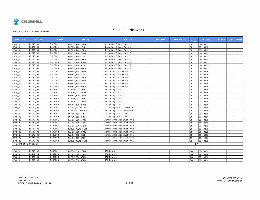
Panel No. IO Tag Zero State One State IO Type PID No. Chassis Slot Point
I/O List - NetworkWILSONVILLE WWTP IMPROVEMENTS
PLC No. Loop ID Loop Title
CP40_01 PMP53_10001FAIL DI 09-I-0115CP40_01 PMP53_10001ON DI 09-I-0115CP40_01 PMP53_10001REM DI 09-I-0115CP40_01 PMP53_10002FAIL DI 09-I-0115CP40_01 PMP53_10002ON DI 09-I-0115CP40_01 PMP53_10002REM DI 09-I-0115CP40_01 PMP53_10003FAIL DI 09-I-0115CP40_01 PMP53_10003ON DI 09-I-0115CP40_01 PMP53_10003REM DI 09-I-0115CP40_01 PMP55_10501FAIL DI 09-I-0116CP40_01 PMP55_10501ON DI 09-I-0116CP40_01 PMP55_10501REM DI 09-I-0116CP40_01 PMP55_10502FAIL DI 09-I-0116CP40_01 PMP55_10502ON DI 09-I-0116CP40_01 PMP55_10502REM DI 09-I-0116CP40_01 CTW55_11001ON DI 09-I-0116CP40_01 CTW55_11001REM DI 09-I-0116CP40_01 PMP55_11001FAIL DI 09-I-0116CP40_01 CTW55_11002ON DI 09-I-0116CP40_01 CTW55_11002REM DI 09-I-0116CP40_01 PMP55_11002FAIL DI 09-I-0116CP40_01 VSH55_11101HIGH DI 09-I-0116CP40 01 VSH55 11102HIGH DI 09-I-0116
PLC40_01 5511101 SE Cooling Tower 1 VibrationPLC40 01 5511102 SE Cooling Tower 2 Vibration
PLC40_01 5511002 SE Cooling Tower 2PLC40_01 5511002 SE Cooling Tower 2
PLC40_01 5511001 SE Cooling Tower 1PLC40_01 5511002 SE Cooling Tower 2
PLC40_01 5511001 SE Cooling Tower 1PLC40_01 5511001 SE Cooling Tower 1
PLC40_01 5510502 SE Cooling Tower Pump 2PLC40_01 5510502 SE Cooling Tower Pump 2
PLC40_01 5510501 SE Cooling Tower Pump 1PLC40_01 5510502 SE Cooling Tower Pump 2
PLC40_01 5510501 SE Cooling Tower Pump 1PLC40_01 5510501 SE Cooling Tower Pump 1
PLC40_01 5310003 Secondary Effluent Pump 3PLC40_01 5310003 Secondary Effluent Pump 3
PLC40_01 5310002 Secondary Effluent Pump 2PLC40_01 5310003 Secondary Effluent Pump 3
PLC40_01 5310002 Secondary Effluent Pump 2PLC40_01 5310002 Secondary Effluent Pump 2
PLC40_01 5310001 Secondary Effluent Pump 1PLC40_01 5310001 Secondary Effluent Pump 1
PLC40_01 5310001 Secondary Effluent Pump 1
CP40_01 VSH55_11102HIGH DI 09 I 0116CP40_01 LSH55_11201HIGH DI 09-I-0116CP40_01 LSH55_11202HIGH DI 09-I-0116CP40_01 FAN91_30501FAIL DI 09-I-0122CP40_01 FAN91_30501ON DI 09-I-0122CP40_01 FAN91_30501REM DI 09-I-0122CP40_01 ISH91_30501HIGH DI 09-I-0122CP40_01 FAN91_30502FAIL DI 09-I-0122CP40_01 FAN91_30502ON DI 09-I-0122CP40_01 FAN91_30502REM DI 09-I-0122CP40_01 ISH91_30502HIGH DI 09-I-0122
67
CP40_01 PMP50_03001RUN DO 09-I-0113CP40_01 PMP50_03002RUN DO 09-I-0113CP40_01 PMP50_03003RUN DO 09-I-0113CP40_01 PMP50_03004RUN DO 09-I-0113PLC40_01 5003004 RAS Pump 4
PLC40_01 5003002 RAS Pump 2PLC40_01 5003003 RAS Pump 3
Count of IO Type: DI
PLC40_01 5003001 RAS Pump 1
PLC40_01 9130502 Aeration Basins Exhaust Fan 2PLC40_01 9130502 Aeration Basins Exhaust Fan 2
PLC40_01 9130502 Aeration Basins Exhaust Fan 2PLC40_01 9130502 Aeration Basins Exhaust Fan 2
PLC40_01 9130501 Aeration Basins Exhaust Fan 1PLC40_01 9130501 Aeration Basins Exhaust Fan 1
PLC40_01 9130501 Aeration Basins Exhaust Fan 1PLC40_01 9130501 Aeration Basins Exhaust Fan 1
PLC40_01 5511201 SE Cooling Tower 1 LevelPLC40_01 5511202 SE Cooling Tower 2 Level
PLC40_01 5511102 SE Cooling Tower 2 Vibration
PW/WBG/425034 JANUARY 2014 ©COPYRIGHT 2014 CH2M HILL 4 of 10
PLC COMPONENTS 40 92 05 SUPPLEMENT

Panel No. IO Tag Zero State One State IO Type PID No. Chassis Slot Point
I/O List - NetworkWILSONVILLE WWTP IMPROVEMENTS
PLC No. Loop ID Loop Title
CP40_01 PMP53_10001RUN DO 09-I-0115CP40_01 PMP53_10002RUN DO 09-I-0115CP40_01 PMP53_10003RUN DO 09-I-0115CP40_01 PMP55_10501RUN DO 09-I-0116CP40_01 PMP55_10502RUN DO 09-I-0116CP40_01 CTW55_11001RUN DO 09-I-0116CP40_01 CTW55_11002RUN DO 09-I-0116CP40_01 FAN91_30501RUN DO 09-I-0122CP40_01 FAN91_30502RUN DO 09-I-0122
13
AI 7AO 7DI 67DO 13Total 94
CP40_02 PMP45_02001SPEED AI 09-I-0127CP40_02 PMP45_02002SPEED AI 09-I-0127PLC40_02 4502002 Basin Drain Pump No. 1
C 0 02 82 000 G d
PLC No.: PLC40_02
PLC40_02 4502001 Filtrate Drain Pump No. 1
Count of IO Type: DO
Total for PLC No.: PLC40_01
PLC40_01 9130501 Aeration Basins Exhaust Fan 1PLC40_01 9130502 Aeration Basins Exhaust Fan 2
PLC40_01 5511001 SE Cooling Tower 1PLC40_01 5511002 SE Cooling Tower 2
PLC40_01 5510501 SE Cooling Tower Pump 1PLC40_01 5510502 SE Cooling Tower Pump 2
PLC40_01 5310002 Secondary Effluent Pump 2PLC40_01 5310003 Secondary Effluent Pump 3
PLC40_01 5310001 Secondary Effluent Pump 1
CP40_02 PMP82_10001SPEED AI 09-I-0125CP40_02 PMP82_10002SPEED AI 09-I-0125CP40_02 PMP90_00101SPEED AI 09-I-0118CP40_02 PMP90_00102SPEED AI 09-I-0118CP40_02 PMP90_00103SPEED AI 09-I-0118
7
CP40_02 PMP45_02001SC AO 09-I-0127CP40_02 PMP45_02002SC AO 09-I-0127CP40_02 PMP82_10001SC AO 09-I-0125CP40_02 PMP82_10002SC AO 09-I-0125CP40_02 PMP90_00101SC AO 09-I-0118CP40_02 PMP90_00102SC AO 09-I-0118CP40_02 PMP90_00103SC AO 09-I-0118
7 Count of IO Type: AO
PLC40_02 9000102 W3 Pump No. 2PLC40_02 9000103 W3 Pump No. 3
PLC40_02 8210002 GBT Feed Pump 2PLC40_02 9000101 W3 Pump No. 1
PLC40_02 4502002 Basin Drain Pump No. 1PLC40_02 8210001 GBT Feed Pump 1
Count of IO Type: AI
PLC40_02 4502001 Filtrate Drain Pump No. 1
PLC40_02 9000102 W3 Pump No. 2PLC40_02 9000103 W3 Pump No. 3
PLC40_02 8210002 GBT Feed Pump 2PLC40_02 9000101 W3 Pump No. 1
PLC40_02 8210001 GBT Feed Pump 1
PW/WBG/425034 JANUARY 2014 ©COPYRIGHT 2014 CH2M HILL 5 of 10
PLC COMPONENTS 40 92 05 SUPPLEMENT

Panel No. IO Tag Zero State One State IO Type PID No. Chassis Slot Point
I/O List - NetworkWILSONVILLE WWTP IMPROVEMENTS
PLC No. Loop ID Loop Title
CP40_02 PMP45_02001FAIL DI 09-I-0127CP40_02 PMP45_02001ON DI 09-I-0127CP40_02 PMP45_02001REM DI 09-I-0127CP40_02 PMP45_02002FAIL DI 09-I-0127CP40_02 PMP45_02002ON DI 09-I-0127CP40_02 PMP45_02002REM DI 09-I-0127CP40_02 CLR50_00101FAIL DI 09-I-0111CP40_02 CLR50_00101ON DI 09-I-0111CP40_02 CLR50_00102FAIL DI 09-I-0111CP40_02 CLR50_00102ON DI 09-I-0111CP40_02 CLR50_00103FAIL DI 09-I-0112CP40_02 CLR50_00103ON DI 09-I-0112CP40_02 SSL50_00103LOW DI 09-I-0112CP40_02 PMP50_01003ON DI 09-I-0112CP40_02 PMP50_20100FAIL DI 09-I-0114CP40_02 PMP50_20100ON DI 09-I-0114CP40_02 PMP50_20100REM DI 09-I-0114CP40_02 USH50_20100LEAK DI 09-I-0114CP40_02 USH50_20100TEMP DI 09-I-0114CP40_02 PMP80_00006FAIL DI 09-I-0127CP40_02 PMP80_00006ON DI 09-I-0127CP40_02 PMP80_00006REM DI 09-I-0127CP40 02 PSH80 00006HIGH DI 09-I-0127
PLC40_02 8000006 TWAS Transfer Pump 1PLC40 02 8000006 TWAS Transfer Pump 1
PLC40_02 8000006 TWAS Transfer Pump 1PLC40_02 8000006 TWAS Transfer Pump 1
PLC40_02 5020100 Secondary Scum PumpPLC40_02 5020100 Secondary Scum Pump
PLC40_02 5020100 Secondary Scum PumpPLC40_02 5020100 Secondary Scum Pump
PLC40_02 5001003 Secondary Clarifier 3 Spray PumpPLC40_02 5020100 Secondary Scum Pump
PLC40_02 5000103 Secondary Clarifier 3PLC40_02 5000103 Secondary Clarifier 3
PLC40_02 5000102 Secondary Clarifier 2PLC40_02 5000103 Secondary Clarifier 3
PLC40_02 5000101 Secondary Clarifier 1PLC40_02 5000102 Secondary Clarifier 2
PLC40_02 4502002 Basin Drain Pump No. 1PLC40_02 5000101 Secondary Clarifier 1
PLC40_02 4502002 Basin Drain Pump No. 1PLC40_02 4502002 Basin Drain Pump No. 1
PLC40_02 4502001 Filtrate Drain Pump No. 1PLC40_02 4502001 Filtrate Drain Pump No. 1
PLC40_02 4502001 Filtrate Drain Pump No. 1
CP40_02 PSH80_00006HIGH DI 09 I 0127CP40_02 PMP80_00007FAIL DI 09-I-0127CP40_02 PMP80_00007ON DI 09-I-0127CP40_02 PMP80_00007REM DI 09-I-0127CP40_02 PSH80_00007HIGH DI 09-I-0127CP40_02 PMP80_00201FAIL DI 09-I-0126CP40_02 PMP80_00201ON DI 09-I-0126CP40_02 PMP80_00201REM DI 09-I-0126CP40_02 PMP80_00202FAIL DI 09-I-0126CP40_02 PMP80_00202ON DI 09-I-0126CP40_02 PMP80_00202REM DI 09-I-0126CP40_02 BLW82_00101FAIL DI 09-I-0128CP40_02 BLW82_00101ON DI 09-I-0128CP40_02 BLW82_00101REM DI 09-I-0128CP40_02 BLW82_00102FAIL DI 09-I-0128CP40_02 BLW82_00102ON DI 09-I-0128CP40_02 BLW82_00102REM DI 09-I-0128
PLC40_02 8200102 WAS Tank BlowerPLC40_02 8200102 WAS Tank Blower
PLC40_02 8200101 TWAS Tank BlowerPLC40_02 8200102 WAS Tank Blower
PLC40_02 8200101 TWAS Tank BlowerPLC40_02 8200101 TWAS Tank Blower
PLC40_02 8000202 Belt Wash Water Pump 2PLC40_02 8000202 Belt Wash Water Pump 2
PLC40_02 8000201 Belt Wash Water Pump 1PLC40_02 8000202 Belt Wash Water Pump 2
PLC40_02 8000201 Belt Wash Water Pump 1PLC40_02 8000201 Belt Wash Water Pump 1
PLC40_02 8000007 TWAS Transfer Pump 2PLC40_02 8000007 TWAS Transfer Pump 2
PLC40_02 8000007 TWAS Transfer Pump 2PLC40_02 8000007 TWAS Transfer Pump 2
PLC40_02 8000006 TWAS Transfer Pump 1
PW/WBG/425034 JANUARY 2014 ©COPYRIGHT 2014 CH2M HILL 6 of 10
PLC COMPONENTS 40 92 05 SUPPLEMENT

Panel No. IO Tag Zero State One State IO Type PID No. Chassis Slot Point
I/O List - NetworkWILSONVILLE WWTP IMPROVEMENTS
PLC No. Loop ID Loop Title
CP40_02 PMP82_10001FAIL DI 09-I-0125CP40_02 PMP82_10001ON DI 09-I-0125CP40_02 PMP82_10001REM DI 09-I-0125CP40_02 USH82_10001LEAK DI 09-I-0125CP40_02 USH82_10001TEMP DI 09-I-0125CP40_02 PMP82_10002FAIL DI 09-I-0125CP40_02 PMP82_10002ON DI 09-I-0125CP40_02 PMP82_10002REM DI 09-I-0125CP40_02 USH82_10002LEAK DI 09-I-0125CP40_02 USH82_10002TEMP DI 09-I-0125CP40_02 LSL82_10201LOW DI 09-I-0125CP40_02 LSL82_10202LOW DI 09-I-0125CP40_02 PMP90_00101FAIL DI 09-I-0118CP40_02 PMP90_00101ON DI 09-I-0118CP40_02 PMP90_00101REM DI 09-I-0118CP40_02 PMP90_00102FAIL DI 09-I-0118CP40_02 PMP90_00102ON DI 09-I-0118CP40_02 PMP90_00102REM DI 09-I-0118CP40_02 PMP90_00103FAIL DI 09-I-0118CP40_02 PMP90_00103ON DI 09-I-0118CP40_02 PMP90_00103REM DI 09-I-0118
60PLC40_02 9000103 W3 Pump No. 3
Count of IO Type: DI
PLC40_02 9000103 W3 Pump No. 3PLC40_02 9000103 W3 Pump No. 3
PLC40_02 9000102 W3 Pump No. 2PLC40_02 9000102 W3 Pump No. 2
PLC40_02 9000101 W3 Pump No. 1PLC40_02 9000102 W3 Pump No. 2
PLC40_02 9000101 W3 Pump No. 1PLC40_02 9000101 W3 Pump No. 1
PLC40_02 8210201 WAS Storage Tank 1 LevelPLC40_02 8210202 WAS Storage Tank 2 Level
PLC40_02 8210002 GBT Feed Pump 2PLC40_02 8210002 GBT Feed Pump 2
PLC40_02 8210002 GBT Feed Pump 2PLC40_02 8210002 GBT Feed Pump 2
PLC40_02 8210001 GBT Feed Pump 1PLC40_02 8210002 GBT Feed Pump 2
PLC40_02 8210001 GBT Feed Pump 1PLC40_02 8210001 GBT Feed Pump 1
PLC40_02 8210001 GBT Feed Pump 1PLC40_02 8210001 GBT Feed Pump 1
CP40_02 PMP45_02001RUN DO 09-I-0127CP40_02 PMP45_02002RUN DO 09-I-0127CP40_02 PMP50_20100RUN DO 09-I-0114CP40_02 PMP80_00006RUN DO 09-I-0127CP40_02 PMP80_00007RUN DO 09-I-0127CP40_02 PMP80_00201RUN DO 09-I-0126CP40_02 PMP80_00202RUN DO 09-I-0126CP40_02 BLW82_00101RUN DO 09-I-0128CP40_02 BLW82_00102RUN DO 09-I-0128CP40_02 PMP82_10001RUN DO 09-I-0125CP40_02 PMP82_10002RUN DO 09-I-0125CP40_02 PMP90_00101RUN DO 09-I-0118CP40_02 PMP90_00102RUN DO 09-I-0118CP40_02 PMP90_00103RUN DO 09-I-0118
14 Count of IO Type: DO
PLC40_02 9000102 W3 Pump No. 2PLC40_02 9000103 W3 Pump No. 3
PLC40_02 8210002 GBT Feed Pump 2PLC40_02 9000101 W3 Pump No. 1
PLC40_02 8200102 WAS Tank BlowerPLC40_02 8210001 GBT Feed Pump 1
PLC40_02 8000202 Belt Wash Water Pump 2PLC40_02 8200101 TWAS Tank Blower
PLC40_02 8000007 TWAS Transfer Pump 2PLC40_02 8000201 Belt Wash Water Pump 1
PLC40_02 5020100 Secondary Scum PumpPLC40_02 8000006 TWAS Transfer Pump 1
PLC40_02 4502001 Filtrate Drain Pump No. 1PLC40_02 4502002 Basin Drain Pump No. 1
PW/WBG/425034 JANUARY 2014 ©COPYRIGHT 2014 CH2M HILL 7 of 10
PLC COMPONENTS 40 92 05 SUPPLEMENT

Panel No. IO Tag Zero State One State IO Type PID No. Chassis Slot Point
I/O List - NetworkWILSONVILLE WWTP IMPROVEMENTS
PLC No. Loop ID Loop Title
AI 7AO 7DI 60DO 14Total 88
CP78_01 CEN78_30101FLOWSP AI 09-I-0129CP78_01 CEN78_30102FLOWSP AI 09-I-0129CP78_01 PMP82_20001SPEED AI 09-I-0128CP78_01 PMP82_20002SPEED AI 09-I-0128
4
CP78_01 PMP82_20001SC AO 09-I-0128CP78_01 PMP82_20002SC AO 09-I-0128
2
CP78_01 CEN78_30101ENABLE DI 09-I-0129CP78_01 CEN78_30101REM DI 09-I-0129CP78_01 CEN78_30102ENABLE DI 09-I-0129
PLC78_01 7830101 Centrifuge 1PLC78_01 7830102 Centrifuge 2
Count of IO Type: AO
PLC78_01 7830101 Centrifuge 1
PLC78_01 8220001 Centrifuge Feed Pump 1PLC78_01 8220002 Centrifuge Feed Pump 2
PLC78_01 8220002 Centrifuge Feed Pump 2 Count of IO Type: AI
PLC78_01 7830102 Centrifuge 2PLC78_01 8220001 Centrifuge Feed Pump 1
PLC No.: PLC78_01
PLC78_01 7830101 Centrifuge 1
Total for PLC No.: PLC40_02
CP78_01 CEN78_30102REM DI 09-I-0129CP78_01 PMP78_40100FAIL DI 09-I-0132CP78_01 PMP78_40100ON DI 09-I-0132CP78_01 PMP78_40100REM DI 09-I-0132CP78_01 LSL78_40200LOW DI 09-I-0132CP78_01 CTW78_40500FAIL DI 09-I-0132CP78_01 CTW78_40500ON DI 09-I-0132CP78_01 CTW78_40500REM DI 09-I-0132CP78_01 VSH78_40600HIGH DI 09-I-0132CP78_01 PMP78_41000FAIL DI 09-I-0132CP78_01 PMP78_41000ON DI 09-I-0132CP78_01 PMP78_41000REM DI 09-I-0132CP78_01 LSL78_41100LOW DI 09-I-0132CP78_01 PMP82_20001FAIL DI 09-I-0128CP78_01 PMP82_20001ON DI 09-I-0128CP78_01 PMP82_20001REM DI 09-I-0128
PLC78_01 8220001 Centrifuge Feed Pump 1PLC78_01 8220001 Centrifuge Feed Pump 1
PLC78_01 7841100 Dryer Condensate Cooling Tower LevelPLC78_01 8220001 Centrifuge Feed Pump 1
PLC78_01 7841000 Dryer Condensate Cooling Tower Spray PumpPLC78_01 7841000 Dryer Condensate Cooling Tower Spray Pump
PLC78_01 7840600 Dryer Condensate Cooling Tower Fan PLC78_01 7841000 Dryer Condensate Cooling Tower Spray Pump
PLC78_01 7840500 Dryer Condensate Cooling Tower FanPLC78_01 7840500 Dryer Condensate Cooling Tower Fan
PLC78_01 7840200 Dryer Condensate Sump Pump LevelPLC78_01 7840500 Dryer Condensate Cooling Tower Fan
PLC78_01 7840100 Dryer Condensate Sump PumpPLC78_01 7840100 Dryer Condensate Sump Pump
PLC78_01 7830102 Centrifuge 2PLC78_01 7840100 Dryer Condensate Sump Pump
PW/WBG/425034 JANUARY 2014 ©COPYRIGHT 2014 CH2M HILL 8 of 10
PLC COMPONENTS 40 92 05 SUPPLEMENT

Panel No. IO Tag Zero State One State IO Type PID No. Chassis Slot Point
I/O List - NetworkWILSONVILLE WWTP IMPROVEMENTS
PLC No. Loop ID Loop Title
CP78_01 PSL82_20001LOW DI 09-I-0128CP78_01 TSH82_20001HIGH DI 09-I-0128CP78_01 PMP82_20002FAIL DI 09-I-0128CP78_01 PMP82_20002ON DI 09-I-0128CP78_01 PMP82_20002REM DI 09-I-0128CP78_01 PSL82_20002LOW DI 09-I-0128CP78_01 TSH82_20002HIGH DI 09-I-0128CP78_01 PSH82_20101HIGH DI 09-I-0128CP78_01 PSH82_20102HIGH DI 09-I-0128CP78_01 LSL82_20201LOW DI 09-I-0128CP78_01 LSL82_20202LOW DI 09-I-0128CP78_01 FAN91_10501FAIL DI 09-I-0120CP78_01 FAN91_10501ON DI 09-I-0120CP78_01 FAN91_10501REM DI 09-I-0120CP78_01 ISL91_10501LOW DI 09-I-0120CP78_01 FAN91_10502FAIL DI 09-I-0120CP78_01 FAN91_10502ON DI 09-I-0120CP78_01 FAN91_10502REM DI 09-I-0120CP78_01 ISL91_10502LOW DI 09-I-0120CP78_01 FAN91_20501FAIL DI 09-I-0121CP78_01 FAN91_20501ON DI 09-I-0121CP78_01 FAN91_20501REM DI 09-I-0121CP78 01 FAN91 20502FAIL DI 09-I-0121PLC78 01 9120502 Biofilter 2 Inline Stack Fan
PLC78_01 9120501 Biofilter 1 Inline Stack FanPLC78_01 9120501 Biofilter 1 Inline Stack Fan
PLC78_01 9110502 Odor Control Fan 2PLC78_01 9120501 Biofilter 1 Inline Stack Fan
PLC78_01 9110502 Odor Control Fan 2PLC78_01 9110502 Odor Control Fan 2
PLC78_01 9110501 Odor Control Fan 1PLC78_01 9110502 Odor Control Fan 2
PLC78_01 9110501 Odor Control Fan 1PLC78_01 9110501 Odor Control Fan 1
PLC78_01 8220202 TWAS Storage Tank 2 LevelPLC78_01 9110501 Odor Control Fan 1
PLC78_01 8220102 Centrifuge Feed Pump 2 Discharge PressurePLC78_01 8220201 TWAS Storage Tank 1 Level
PLC78_01 8220002 Centrifuge Feed Pump 2 PLC78_01 8220101 Centrifuge Feed Pump 1 Discharge Pressure
PLC78_01 8220002 Centrifuge Feed Pump 2PLC78_01 8220002 Centrifuge Feed Pump 2
PLC78_01 8220002 Centrifuge Feed Pump 2PLC78_01 8220002 Centrifuge Feed Pump 2
PLC78_01 8220001 Centrifuge Feed Pump 1 PLC78_01 8220001 Centrifuge Feed Pump 1
CP78_01 FAN91_20502FAIL DI 09 I 0121CP78_01 FAN91_20502ON DI 09-I-0121CP78_01 FAN91_20502REM DI 09-I-0121
44
CP78_01 CEN78_30101CIP DO 09-I-0129CP78_01 CEN78_30101RUN DO 09-I-0129CP78_01 CEN78_30102CIP DO 09-I-0129CP78_01 CEN78_30102RUN DO 09-I-0129CP78_01 PMP78_40100RUN DO 09-I-0132CP78_01 CTW78_40500RUN DO 09-I-0132CP78_01 PMP78_41000RUN DO 09-I-0132CP78_01 PMP82_20001RUN DO 09-I-0128CP78_01 PMP82_20002RUN DO 09-I-0128CP78_01 FAN91_10501RUN DO 09-I-0120CP78_01 FAN91_10502RUN DO 09-I-0120CP78_01 FAN91_20501RUN DO 09-I-0121
PLC78_01 9110502 Odor Control Fan 2PLC78_01 9120501 Biofilter 1 Inline Stack Fan
PLC78_01 8220002 Centrifuge Feed Pump 2PLC78_01 9110501 Odor Control Fan 1
PLC78_01 7841000 Dryer Condensate Cooling Tower Spray PumpPLC78_01 8220001 Centrifuge Feed Pump 1
PLC78_01 7840100 Dryer Condensate Sump PumpPLC78_01 7840500 Dryer Condensate Cooling Tower Fan
PLC78_01 7830102 Centrifuge 2PLC78_01 7830102 Centrifuge 2
PLC78_01 7830101 Centrifuge 1PLC78_01 7830101 Centrifuge 1
PLC78_01 9120502 Biofilter 2 Inline Stack Fan Count of IO Type: DI
PLC78_01 9120502 Biofilter 2 Inline Stack FanPLC78_01 9120502 Biofilter 2 Inline Stack Fan
PW/WBG/425034 JANUARY 2014 ©COPYRIGHT 2014 CH2M HILL 9 of 10
PLC COMPONENTS 40 92 05 SUPPLEMENT

Panel No. IO Tag Zero State One State IO Type PID No. Chassis Slot Point
I/O List - NetworkWILSONVILLE WWTP IMPROVEMENTS
PLC No. Loop ID Loop Title
CP78_01 FAN91_20502RUN DO 09-I-012113
AI 4AO 2DI 44DO 13Total 63
AI 22AO 16DI 204DO 51Total 293
Total for PLC No.: PLC78_01
Total Summary
PLC78_01 9120502 Biofilter 2 Inline Stack Fan Count of IO Type: DO
PW/WBG/425034 JANUARY 2014 ©COPYRIGHT 2014 CH2M HILL 10 of 10
PLC COMPONENTS 40 92 05 SUPPLEMENT
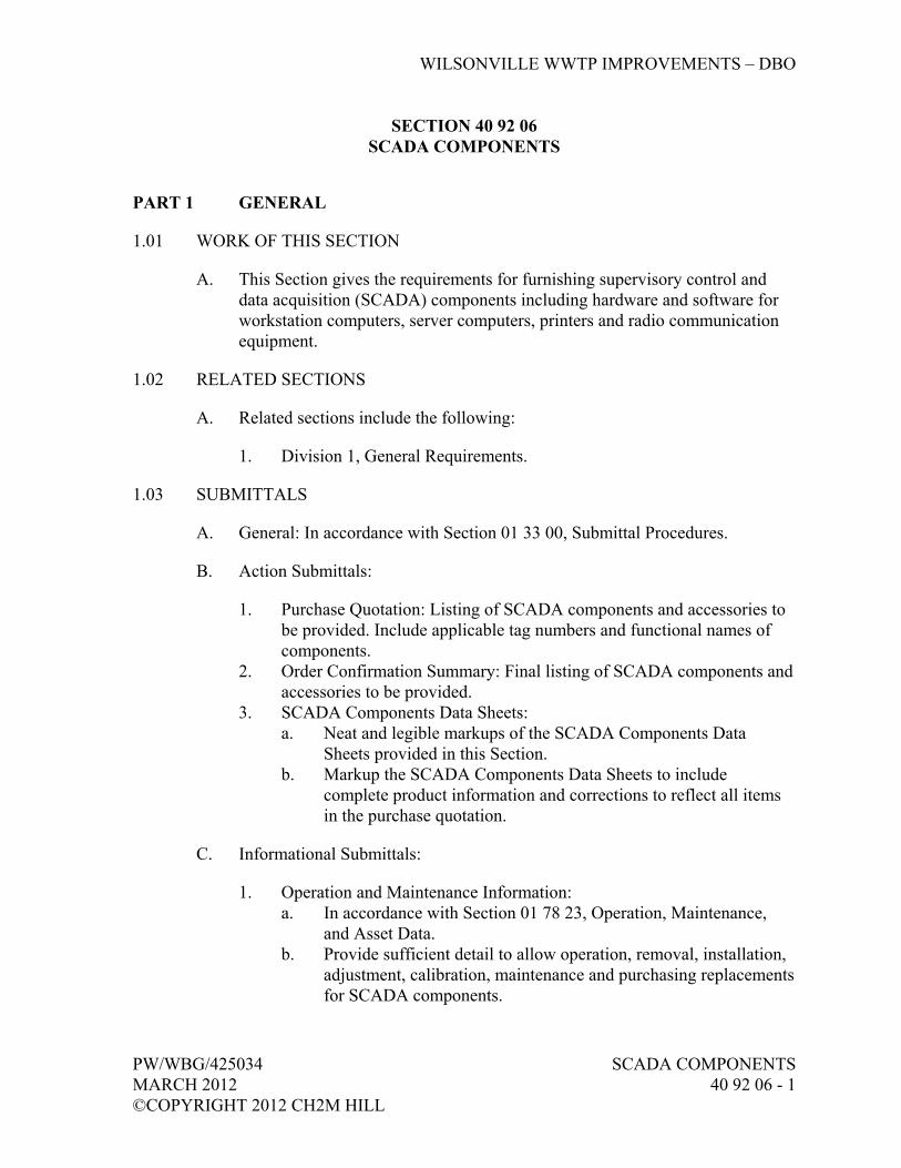
WILSONVILLE WWTP IMPROVEMENTS – DBO
PW/WBG/425034 SCADA COMPONENTS MARCH 2012 40 92 06 - 1 ©COPYRIGHT 2012 CH2M HILL
SECTION 40 92 06 SCADA COMPONENTS
PART 1 GENERAL
1.01 WORK OF THIS SECTION
A. This Section gives the requirements for furnishing supervisory control and data acquisition (SCADA) components including hardware and software for workstation computers, server computers, printers and radio communication equipment.
1.02 RELATED SECTIONS
A. Related sections include the following:
1. Division 1, General Requirements.
1.03 SUBMITTALS
A. General: In accordance with Section 01 33 00, Submittal Procedures.
B. Action Submittals:
1. Purchase Quotation: Listing of SCADA components and accessories to be provided. Include applicable tag numbers and functional names of components.
2. Order Confirmation Summary: Final listing of SCADA components and accessories to be provided.
3. SCADA Components Data Sheets: a. Neat and legible markups of the SCADA Components Data
Sheets provided in this Section. b. Markup the SCADA Components Data Sheets to include
complete product information and corrections to reflect all items in the purchase quotation.
C. Informational Submittals:
1. Operation and Maintenance Information: a. In accordance with Section 01 78 23, Operation, Maintenance,
and Asset Data. b. Provide sufficient detail to allow operation, removal, installation,
adjustment, calibration, maintenance and purchasing replacements for SCADA components.

WILSONVILLE WWTP IMPROVEMENTS – DBO
SCADA COMPONENTS PW/WBG/425034 40 92 06 - 2 MARCH 2012 ©COPYRIGHT 2012 CH2M HILL
c. Name, address and telephone number of the SCADA Supplier’s local service representative.
d. Complete list of supplied SCADA components with full model numbers, including spare parts and test equipment provided.
2. Manufacturer’s Original Copies of Hardware, Software and Installation, Assembly and Operations Manuals for SCADA components. Manuals shall include the following information: a. General descriptive information covering the basic features. b. Physical description covering layout and installation requirements
and all environmental constraints. c. Functional and operational descriptions covering the procedures
for programming, operation, startup, shutdown, and of the SCADA equipment and explaining how the various functions are performed.
d. Maintenance procedures covering checkout and troubleshooting: 1) Checkout procedures shall provide the means to verify the
satisfactory operation of equipment. 2) Troubleshooting procedures shall serve as a guide in
determining faulty components. e. Wiring and schematic diagrams. f. Safety considerations relating to operation and maintenance
procedures. 3. Content for Each O&M Manual:
a. Table of Contents. b. Operations procedures. c. Installation requirements and procedures. d. Maintenance requirements and procedures. e. Troubleshooting procedures. f. Internal schematic and wiring diagrams.
4. List of spares, expendables, test equipment and tools provided. 5. List of additional recommended spares, expendables, test equipment,
and tools. Include quantities, unit prices, and total costs. 6. WWTP to Public Works Radio System Analysis and Design:
a. Radio path evaluation and fade margin calculation. b. Antenna mounting height requirement. c. Radio panel layouts and wiring diagrams. d. Antenna mounting and grounding details.
1.04 DELIVERY, STORAGE, AND HANDLING
A. In accordance with Section 01 61 00, Common Product Requirements.
B. Packaged at the factory prior to shipment to protect each item from damage during shipment and storage. Containers protected against impact, abrasion,
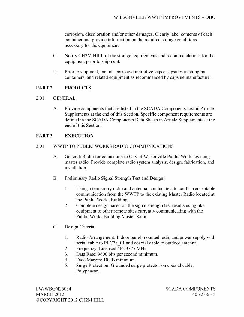
WILSONVILLE WWTP IMPROVEMENTS – DBO
PW/WBG/425034 SCADA COMPONENTS MARCH 2012 40 92 06 - 3 ©COPYRIGHT 2012 CH2M HILL
corrosion, discoloration and/or other damages. Clearly label contents of each container and provide information on the required storage conditions necessary for the equipment.
C. Notify CH2M HILL of the storage requirements and recommendations for the equipment prior to shipment.
D. Prior to shipment, include corrosive inhibitive vapor capsules in shipping containers, and related equipment as recommended by capsule manufacturer.
PART 2 PRODUCTS
2.01 GENERAL
A. Provide components that are listed in the SCADA Components List in Article Supplements at the end of this Section. Specific component requirements are defined in the SCADA Components Data Sheets in Article Supplements at the end of this Section.
PART 3 EXECUTION
3.01 WWTP TO PUBLIC WORKS RADIO COMMUNICATIONS
A. General: Radio for connection to City of Wilsonville Public Works existing master radio. Provide complete radio system analysis, design, fabrication, and installation.
B. Preliminary Radio Signal Strength Test and Design:
1. Using a temporary radio and antenna, conduct test to confirm acceptable communication from the WWTP to the existing Master Radio located at the Public Works Building.
2. Complete design based on the signal strength test results using like equipment to other remote sites currently communicating with the Public Works Building Master Radio.
C. Design Criteria:
1. Radio Arrangement: Indoor panel-mounted radio and power supply with serial cable to PLC78_01 and coaxial cable to outdoor antenna.
2. Frequency: Licensed 462.3375 MHz. 3. Data Rate: 9600 bits per second minimum. 4. Fade Margin: 10 dB minimum. 5. Surge Protection: Grounded surge protector on coaxial cable,
Polyphasor.
WILSONVILLE WWTP IMPROVEMENTS – DBO
SCADA COMPONENTS PW/WBG/425034 40 92 06 - 4 MARCH 2012 ©COPYRIGHT 2012 CH2M HILL
6. Power Supply: 120V ac. Provide dc power supply as required for radio equipment.
3.02 SUPPLEMENTS
A. The supplements listed below, following “End of Section,” are part of this Specification.
1. SCADA Components List. 2. SCADA Components Data Sheets.
END OF SECTION
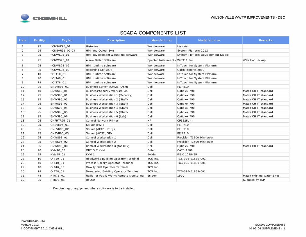
WILSONVILLE WWTP IMPROVEMENTS - DBO
Item Facility Tag No. Description Manufacturer Model Number Remarks
1 95 *CNSVR95_01 Historian Wonderware Historian2 95 *CNSVR95_02,03 HMI and Object Svrs Wonderware System Platform 20123 95 *CNWS95_01 HMI development & runtime software Wonderware System Platform Development Studio
4 95 *CNWS95_01 Alarm Dialer Software Specter Instruments Win911 Pro With Hot backup
5 95 *CNWS95_02 HMI runtime software Wonderware InTouch for System Platform6 95 *CNWS95_02 Reporting Software Wonderware Quick Reports 20127 10 *OIT10_01 HMI runtime software Wonderware InTouch for System Platform8 40 *OIT40_01 HMI runtime software Wonderware InTouch for System Platform9 78 *OIT78_01 HMI runtime software Wonderware InTouch for System Platform10 95 BNSVR95_01 Business Server (CMMS, O&M) Dell PE R61011 40 BNWS40_01 Business/Security Workstation Dell Optiplex 790 Match CH IT standard12 95 BNWS95_01 Business Workstation 1 (Security) Dell Optiplex 790 Match CH IT standard13 95 BNWS95_02 Business Workstation 2 (Staff) Dell Optiplex 790 Match CH IT standard14 95 BNWS95_03 Business Workstation 3 (Staff) Dell Optiplex 790 Match CH IT standard15 95 BNWS95_04 Business Workstation 4 (Staff) Dell Optiplex 790 Match CH IT standard16 95 BNWS95_05 Business Workstation 5 (Staff) Dell Optiplex 790 Match CH IT standard17 95 BNWS95_06 Business Workstation 6 (Lab) Dell Optiplex 790 Match CH IT standard18 95 CNPRTR95_01 Control Network Printer HP CP5225dn
SCADA COMPONENTS LIST
19 95 CNSVR95_01 Server (HMI) Dell PE R71020 95 CNSVR95_02 Server (AOS1, PDC)) Dell PE R71021 95 CNSVR95_03 Server (AOS2, GR) Dell PE R71022 95 CNWS95_01 Control Workstation 1 Dell Precision T3500 Minitower23 95 CNWS95_02 Control Workstation 2 Dell Precision T3500 Minitower24 95 CNWS95_03 Control Workstation 3 (for City) Dell Optiplex 790 Match CH IT standard25 40 KVM40_03 GBT OIT KVM Gefen CAT5-150026 95 KVM95_01 KVM 1 Belkin FIDC 108B-SR27 10 OIT10_01 Headworks Building Operator Terminal TCS Inc. TCS-025-01889-00128 40 OIT40_01 Process Gallery Operator Terminal TCS Inc. TCS-025-01889-00129 40 OIT40_03 Gravity Belt Operator Terminal TCS Inc.30 78 OIT78_01 Dewatering Building Operator Terminal TCS Inc. TCS-025-01889-00131 78 RTU78_01 Radio for Public Works Remote Monitoring Esteem 192C Match existing Water Sites32 95 RTR95_01 Router Supplied by ISP
* Denotes tag of equipment where software is to be installed
PW/WBG/425034 MARCH 2012©COPYRIGHT 2012 CH2M HILL
SCADA COMPONENTS40 92 06 SUPPLEMENT - 1


Wilsonville WWTP Improvements
SCADA COMPONENTS DATA SHEETS
PW/WBG/425034 MARCH 2012 ©COPYRIGHT 2012 CH2M HILL
SCADA COMPONENTS40 92 06 SUPPLEMENT

KVM (KEYBOARD, VIDEO,
MOUSE)
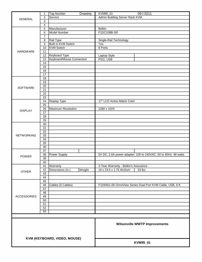
1 Tag Number Drawing KVM95_01 09-I-021123456789
101112 Laptop Style13 PS/2, USB1415161718192021222324252627282930313233343536373839404142 Dimensions (in.) Weight 19 x 23.5 x 1.75 WxDxH 33 lbs4344454647484950515253
Display Type
Maximum Resolution 1280 x 1024
17" LCD Active-Matrix Color
F1DC108B-SRModel Number
Rail Type Single-Rail Technology
GENERAL
HARDWARE
NETWORKING
Admin Building Server Rack KVM
Belkin
Yes8 Ports
Service
Manufacturer
Built in KVM SwitchKVM Switch
Keyboard TypeKeyboard/Mouse Connection
SOFTWARE
Cables (5 Cables) F1D9401-06 OmniView Series Dual-Port KVM Cable, USB, 6 ft.
2-Year Warranty - Belkin's Assurance
OTHER
POWER
KVM95_01
Wilsonville WWTP Improvements
KVM (KEYBOARD, VIDEO, MOUSE)
DISPLAY
Power Supply 5V DC, 2.6A power adapter; 100 to 240VAC; 50 to 60Hz; 48 watts
ACCESSORIES
Warranty

1 Tag Number Drawing KVM40_03 09-I-021623456789
101112131415161718192021222324252627282930313233343536373839404142 Dimensions (in.) Weight 8.4 x 4.2 x 1.6 WxDxH 6 lbs4344454647484950515253
KVM40_03
Wilsonville WWTP Improvements
KVM (KEYBOARD, VIDEO, MOUSE)
RECEIVE UNIT
Video Out 1
Cat-5 VideoCat-5 USB/Aud2 USB OUT
Power Supply
Two CAT5 cables to extend up to 330 feet.CAT5
5V DC, power adapter; 100 to 240VAC; 50 to 60Hz;
ACCESSORIES
Warranty
SEND UNIT
Cables Video, USB, Audio (6 Ft)
30 day
OTHER
POWER
Monitor OutVideo InCat-5 VideoCat-5 USB/Aud
Power
CAT5-1500Model Number
RJ-45 input extends VGA signalsRJ-45 input extends USB, and audio signals
GENERAL
HARDWARE
NETWORKING
GBT OIT KVM
Gefen
5 VDC
Service
Manufacturer
RF-45 input connects CAT-5 cable to receive extended VGARF-45 input connects CAT-5 cable to receive extended USB
Power
Video Out 2 HD 15 output connecting to remote monitor (nirrored video)
USB input from computer
Two USB type A Outputs connects to USB devices
5 VDCHD 15 output connecting to remote monitor
Output for local monitor (not used)VGA
USB Input

PRINTER

1 Tag Number Drawing CNPRTR95_01 09-I-020123456789
101112131415161718192021222324252627282930313233343536373839404142 Dimensions (in.) Weight 22 x 24 x 14 inches 90.2 lbs4344454647484950515253
Ethernet
Control Panel 2 line 16 character backlit display
HP PCL 6, 5c, postscriptPassword protected embedded Web Server
CP5225nModel Number
Speed 20 ppm
GENERAL
HARDWARE
NETWORKING
Control Network Printer
HP
192 MB
84 scalable true type fonts
600 x 600 dpi2 tray, up to 12 x 18 inch
Service
Manufacturer
Memory
ResolutionPaper Input
Fonts
SOFTWARE
10/100 Base-T port built in
5 year Next Day Business Support
CountertopOTHER
POWER
Print DriverSecurity
CNPRTR95_01
Wilsonville WWTP Improvements
Printer
DISPLAY
Power Supply
Mounting
High Speed USB 2.0USB
120 VAC
ACCESSORIES
Warranty

RADIO

1 Tag Number Drawing RTU78_01 09-I-020123456789
101112131415 Dimensions Weight 2.5 in. x 8.2 in. x 9.4 in 5 LBS1617181920212223242526272829303132333435363738394041424344454647484950515253
RTU78_01
Wilsonville WWTP Improvements
Radio
Power Supply 12 VDC with 120 VAC adapter
ACCESSORIES
Bandpass FilterAntennaLightning Arrestor
As needed, TXC RX Systems Inc Yagi directional, Kathrein Ca7Include
minus 30 to 60 deg C
OTHER
Operating Temperature
POWER
RF PowerData Rate
192CModel Number
Frequency 462.3375 MHz
GENERAL
HARDWARE
WWTP Radio for Public Works Remote Monitoring
Esteem
2 to 5 Watts600 to 19,200 Baud
Service
Manufacturer

SERVER
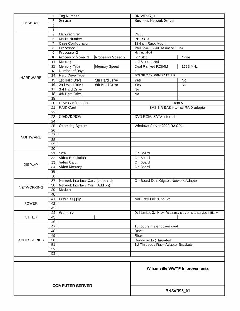
123456789
10 Processor Speed 1 Processor Speed 2 2.4Ghz None1112 Memory Type Memory Speed Dual Ranked RDIMM 1333 MHz131415 1st Hard Drive 5th Hard Drive Yes No 16 2nd Hard Drive 6th Hard Drive Yes No17 3rd Hard Drive No 18 4th Hard Drive No 1920212223242526272829303132333435363738 Network Interface Card (Add on)394041424344454647484950 Ready Rails (Threaded)515253
Bezel
OTHERWarranty
DISPLAY
BNSVR95_01
Wilsonville WWTP Improvements
COMPUTER SERVER
ACCESSORIES
POWER
Modem
On Board
10 foot/ 3 meter power cord
Dell Limited 3yr Hrdwr Warranty plus on site service initial yr
Riser
1U Threaded Rack Adapter Brackets
SOFTWARE
Operating System
Intel Xeon E5640,8M Cache,Turbo
DELLPE R310
Drive Configuration
CD/DVD/ROM DVD ROM, SATA Internal
RAID Card
Windows Server 2008 R2 SP1
Business Network ServerGENERAL
HARDWARE
NETWORKING
Hard Drive Type
Memory
Tag Number
Model Number
Service
Manufacturer
BNSVR95_01
Processor 1Not installed
Number of Bays 4
Case Configuration 19-Inch Rack Mount
Raid 5SAS 6iR SAS internal RAID adapter
4 GB optimized
Processor 2
500 GB 7.2K RPM SATA 3.5
Network Interface Card (on board)
Power Supply Non-Redundant 350W
SizeVideo ResolutionVideo CardVideo Memory
On BoardOn Board
On-Board Dual Gigabit Network Adapter
On Board
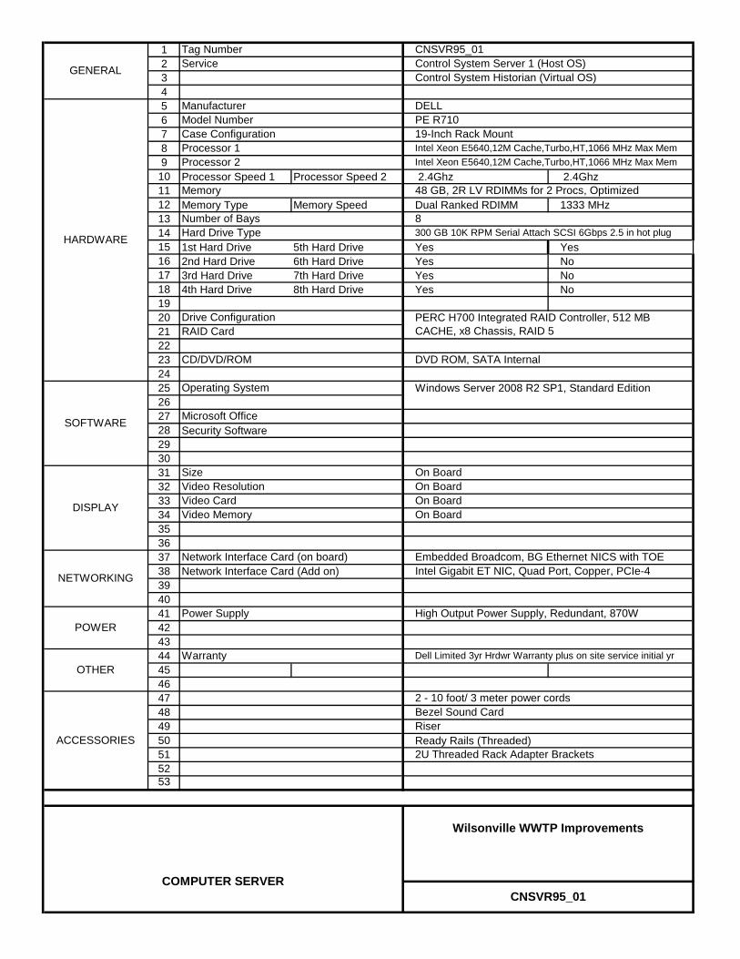
123456789
10 Processor Speed 1 Processor Speed 2 2.4Ghz 2.4Ghz1112 Memory Type Memory Speed Dual Ranked RDIMM 1333 MHz131415 1st Hard Drive 5th Hard Drive Yes Yes16 2nd Hard Drive 6th Hard Drive Yes No17 3rd Hard Drive 7th Hard Drive Yes No18 4th Hard Drive 8th Hard Drive Yes No19202122232425262728 Security Software29303132333435363738 Network Interface Card (Add on)394041424344454647484950 Ready Rails (Threaded)515253
Intel Gigabit ET NIC, Quad Port, Copper, PCIe-4
Bezel Sound Card
OTHERWarranty
DISPLAY
CNSVR95_01
Wilsonville WWTP Improvements
COMPUTER SERVER
ACCESSORIES
POWER
On Board
2 - 10 foot/ 3 meter power cords
Dell Limited 3yr Hrdwr Warranty plus on site service initial yr
Riser
2U Threaded Rack Adapter Brackets
Control System Historian (Virtual OS)
Operating System
Intel Xeon E5640,12M Cache,Turbo,HT,1066 MHz Max Mem
DELLPE R710
Drive Configuration
CD/DVD/ROM DVD ROM, SATA Internal
RAID Card
Windows Server 2008 R2 SP1, Standard Edition
PERC H700 Integrated RAID Controller, 512 MB CACHE, x8 Chassis, RAID 5
GENERAL
HARDWARE
NETWORKING
Microsoft Office
Hard Drive Type
Memory
Tag Number
Model Number
Service
Manufacturer
SOFTWARE
CNSVR95_01
Processor 1Intel Xeon E5640,12M Cache,Turbo,HT,1066 MHz Max Mem
Number of Bays 8
Case Configuration 19-Inch Rack Mount
48 GB, 2R LV RDIMMs for 2 Procs, Optimized
Processor 2
300 GB 10K RPM Serial Attach SCSI 6Gbps 2.5 in hot plug
Control System Server 1 (Host OS)
Network Interface Card (on board)
Power Supply High Output Power Supply, Redundant, 870W
SizeVideo ResolutionVideo CardVideo Memory
On BoardOn Board
Embedded Broadcom, BG Ethernet NICS with TOE
On Board
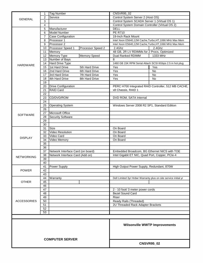
123456789
10 Processor Speed 1 Processor Speed 2 2.4Ghz 2.4Ghz1112 Memory Type Memory Speed Dual Ranked RDIMM 1333 MHz131415 1st Hard Drive 5th Hard Drive Yes Yes16 2nd Hard Drive 6th Hard Drive Yes No17 3rd Hard Drive 7th Hard Drive Yes No18 4th Hard Drive 8th Hard Drive Yes No19202122232425262728 Security Software29303132333435363738 Network Interface Card (Add on)394041424344454647484950 Ready Rails (Threaded)515253
Network Interface Card (on board)
Power Supply High Output Power Supply, Redundant, 870W
SizeVideo ResolutionVideo CardVideo Memory
Bezel Sound CardRiser
2U Threaded Rack Adapter Brackets
Operating System
CNSVR95_02
Processor 1Intel Xeon E5640,12M Cache,Turbo,HT,1066 MHz Max Mem
Number of Bays 8
Case Configuration 19-Inch Rack Mount
Control System Server 2 (Host OS)Control System SCADA Server 1 (Virtual OS 1)
Intel Xeon E5640,12M Cache,Turbo,HT,1066 MHz Max Mem
Control System Domain Controller (Virtual OS 2)DELL
48 GB, 2R LV RDIMMs for 2 Procs, Optimized
Processor 2
1460 GB 15K RPM Serial Attach SCSI 6Gbps 2.5 in hot plug
Drive Configuration
CD/DVD/ROM DVD ROM, SATA Internal
RAID CardPERC H700 Integrated RAID Controller, 512 MB CACHE, x8 Chassis, RAID 1
GENERAL
HARDWARE
NETWORKING
Microsoft Office
Hard Drive Type
Memory
Tag Number
Model Number
Service
ManufacturerPE R710
SOFTWARE
Embedded Broadcom, BG Ethernet NICS with TOE
2 - 10 foot/ 3 meter power cords
Dell Limited 3yr Hrdwr Warranty plus on site service initial yrOTHER
Warranty
DISPLAY
CNSVR95_02
Wilsonville WWTP Improvements
COMPUTER SERVER
ACCESSORIES
POWER
On Board
Intel Gigabit ET NIC, Quad Port, Copper, PCIe-4
Windows Server 2008 R2 SP1, Standard Edition
On BoardOn BoardOn Board

123456789
10 Processor Speed 1 Processor Speed 2 2.4Ghz 2.4Ghz1112 Memory Type Memory Speed Dual Ranked RDIMM 1333 MHz131415 1st Hard Drive 5th Hard Drive Yes Yes16 2nd Hard Drive 6th Hard Drive Yes No17 3rd Hard Drive 7th Hard Drive Yes No18 4th Hard Drive 8th Hard Drive Yes No19202122232425262728 Security Software29303132333435363738 Network Interface Card (Add on)394041424344454647484950 Ready Rails (Threaded)515253
Network Interface Card (on board)
Power Supply High Output Power Supply, Redundant, 870W
SizeVideo ResolutionVideo CardVideo Memory
On BoardOn Board
Embedded Broadcom, BG Ethernet NICS with TOE
On Board
CNSVR95_03
Processor 1Intel Xeon E5640,12M Cache,Turbo,HT,1066 MHz Max Mem
Number of Bays 8
Case Configuration 19-Inch Rack Mount
48 GB, 2R LV RDIMMs for 2 Procs, Optimized
Processor 2
1460 GB 15K RPM Serial Attach SCSI 6Gbps 2.5 in hot plug
Windows Server 2008 R2 SP1, Standard Edition
Control System Server 3 (Host OS)GENERAL
HARDWARE
NETWORKING
Microsoft Office
Hard Drive Type
Memory
Tag Number
Model Number
Service
Manufacturer
SOFTWARE
Control System SCADA Server 2 (Virtual OS 1)
Operating System
Intel Xeon E5640,12M Cache,Turbo,HT,1066 MHz Max Mem
Control System Galaxy Repository (Virtual OS 2)DELLPE R710
Drive Configuration
CD/DVD/ROM DVD ROM, SATA Internal
RAID CardPERC H700 Integrated RAID Controller, 512 MB CACHE, x8 Chassis, RAID 1
2 - 10 foot/ 3 meter power cords
Dell Limited 3yr Hrdwr Warranty plus on site service initial yr
Riser
2U Threaded Rack Adapter Brackets
OTHERWarranty
DISPLAY
CNSVR95_03
Wilsonville WWTP Improvements
COMPUTER SERVER
ACCESSORIES
POWER
On Board
Intel Gigabit ET NIC, Quad Port, Copper, PCIe-4
Bezel Sound Card

SCADA SOFTWARE

1 Tag Number Drawing N/A N/A234 Part # QTY5 SP-4350A 16 97-1260 1 Wonderware Development Studio Unlimited7 01-2622 6 InTouch for System Platform w/HistClient8 56-00004 19
101112131415161718 10-7002 11920212223242526272829303132333435363738394041424344454647484950515253
N/A
Wilsonville WWTP Improvements
SCADA SOFTWARE
DISPLAY
Resolution
ACCESSORIES
Service
SUPPORT
OTHER
SCADA Software - WonderWare
DescriptionWonderware System Platform 2012
Wonderware Customer First - Standard Level
GENERAL
SOFTWARE
Wonderware QuickReports 2012
1920 x 1080

1 Tag Number Drawing N/A 09-I-0201234 Part # QTY5 Win911/Pro 16 Win911/Pro-HB 1789
101112131415161718 WIN-911-ESP-R 11920212223242526272829303132333435363738394041 Part # QTY42 WIN-911/TAPI/USB 24344454647484950515253
N/A
Wilsonville WWTP Improvements
SCADA SOFTWARE
DISPLAY
Specter Instruments External USB modem
ACCESSORIES
Service
SUPPORT
Description
OTHER
SCADA Software - Alarm Dialer
DescriptionSpecter Instruments Alarm Dialer
Additional Year of Support
GENERAL
SOFTWARE
Specter Instruments Alarm Dialer Hot Backup

WORK STATION

1 Tag Number Drawing BNWS40_01 09-I-020123456789
101112 320GB 3.5 6.0 Gb/s SATA 13141516171819202122232425262728293031323334353637 Battery Life Type38394041424344454647484950515253
Network
512 MB
Wireless Device None
Drive Configuration
CD/DVD/ROM
Non RAID
16x DVD +/- RW
AMD Radeon HD 6350
20 inch P2011H WFP
3.3 GHz4GB DDR3 non-ECC SDRAM 1333MHz
None (Installed by CH2M Hill IT)None (Installed by CH2M Hill IT)
Optiplex 790 DesktopModel Number
Processor Intel Core i3 2120
OTHER
Warranty
1st Hard Drive2nd Hard Drive
Business/Security Workstation
DELL
Operating System Windows 7 Professional, Media, 64 bit
GENERAL
HARDWARE
NETWORKING
POWER
Microsoft OfficeSecurity Software
Processor SpeedMemory
ACCESSORIES
Service
Manufacturer
SOFTWARE
Embedded Intel GB Ethernet
KeyboardMousePower Cord
3yr NBD
3 year ProSupport
BNWS40_01
Wilsonville WWTP Improvements
COMPUTER WORKSTATION
DISPLAY
SizeResolutionGraphics CardVideo Memory
Power Supply
Support
NoneModemBlue Tooth None

1 Tag Number Drawing BNWS95_01 09-I-020123456789
101112 320GB 3.5 6.0 Gb/s SATA 13141516171819202122232425262728293031323334353637 Battery Life Type38394041424344454647484950515253
BNWS95_01
Wilsonville WWTP Improvements
COMPUTER WORKSTATION
DISPLAY
SizeResolutionGraphics CardVideo Memory
Power Supply
Support
NoneModemBlue Tooth None
ACCESSORIES
Service
Manufacturer
SOFTWARE
Embedded Intel GB Ethernet
KeyboardMousePower Cord
3yr NBD
3 year ProSupportOTHER
Warranty
1st Hard Drive2nd Hard Drive
Business Workstation 1 (Security)
DELL
Operating System Windows 7 Professional, Media, 64 bit
GENERAL
HARDWARE
NETWORKING
POWER
Microsoft OfficeSecurity Software
Processor SpeedMemory
3.3 GHz4GB DDR3 non-ECC SDRAM 1333MHz
None (Installed by CH2M Hill IT)None (Installed by CH2M Hill IT)
Optiplex 790 DesktopModel Number
Processor Intel Core i3 2120
512 MB
Wireless Device None
Drive Configuration
CD/DVD/ROM
Non RAID
16x DVD +/- RW
AMD Radeon HD 6350
20 inch P2011H WFP
Network

1 Tag Number Drawing BNWS95_02 09-I-020123456789
101112 320GB 3.5 6.0 Gb/s SATA 13141516171819202122232425262728293031323334353637 Battery Life Type38394041424344454647484950515253
BNWS95_02
Wilsonville WWTP Improvements
COMPUTER WORKSTATION
DISPLAY
SizeResolutionGraphics CardVideo Memory
Power Supply
Support
NoneModemBlue Tooth None
ACCESSORIES
Service
Manufacturer
SOFTWARE
Embedded Intel GB Ethernet
KeyboardMousePower Cord
3yr NBD
3 year ProSupportOTHER
Warranty
1st Hard Drive2nd Hard Drive
Business Workstation 2 (Staff)
DELL
Operating System Windows 7 Professional, Media, 64 bit
GENERAL
HARDWARE
NETWORKING
POWER
Microsoft OfficeSecurity Software
Processor SpeedMemory
3.3 GHz4GB DDR3 non-ECC SDRAM 1333MHz
None (Installed by CH2M Hill IT)None (Installed by CH2M Hill IT)
Optiplex 790 DesktopModel Number
Processor Intel Core i3 2120
512 MB
Wireless Device None
Drive Configuration
CD/DVD/ROM
Non RAID
16x DVD +/- RW
AMD Radeon HD 6350
20 inch P2011H WFP
Network

1 Tag Number Drawing BNWS95_03 09-I-020123456789
101112 320GB 3.5 6.0 Gb/s SATA 13141516171819202122232425262728293031323334353637 Battery Life Type38394041424344454647484950515253
BNWS95_03
Wilsonville WWTP Improvements
COMPUTER WORKSTATION
DISPLAY
SizeResolutionGraphics CardVideo Memory
Power Supply
Support
NoneModemBlue Tooth None
ACCESSORIES
Service
Manufacturer
SOFTWARE
Embedded Intel GB Ethernet
KeyboardMousePower Cord
3yr NBD
3 year ProSupportOTHER
Warranty
1st Hard Drive2nd Hard Drive
Business Workstation 3 (Staff)
DELL
Operating System Windows 7 Professional, Media, 64 bit
GENERAL
HARDWARE
NETWORKING
POWER
Microsoft OfficeSecurity Software
Processor SpeedMemory
3.3 GHz4GB DDR3 non-ECC SDRAM 1333MHz
None (Installed by CH2M Hill IT)None (Installed by CH2M Hill IT)
Optiplex 790 DesktopModel Number
Processor Intel Core i3 2120
512 MB
Wireless Device None
Drive Configuration
CD/DVD/ROM
Non RAID
16x DVD +/- RW
AMD Radeon HD 6350
20 inch P2011H WFP
Network
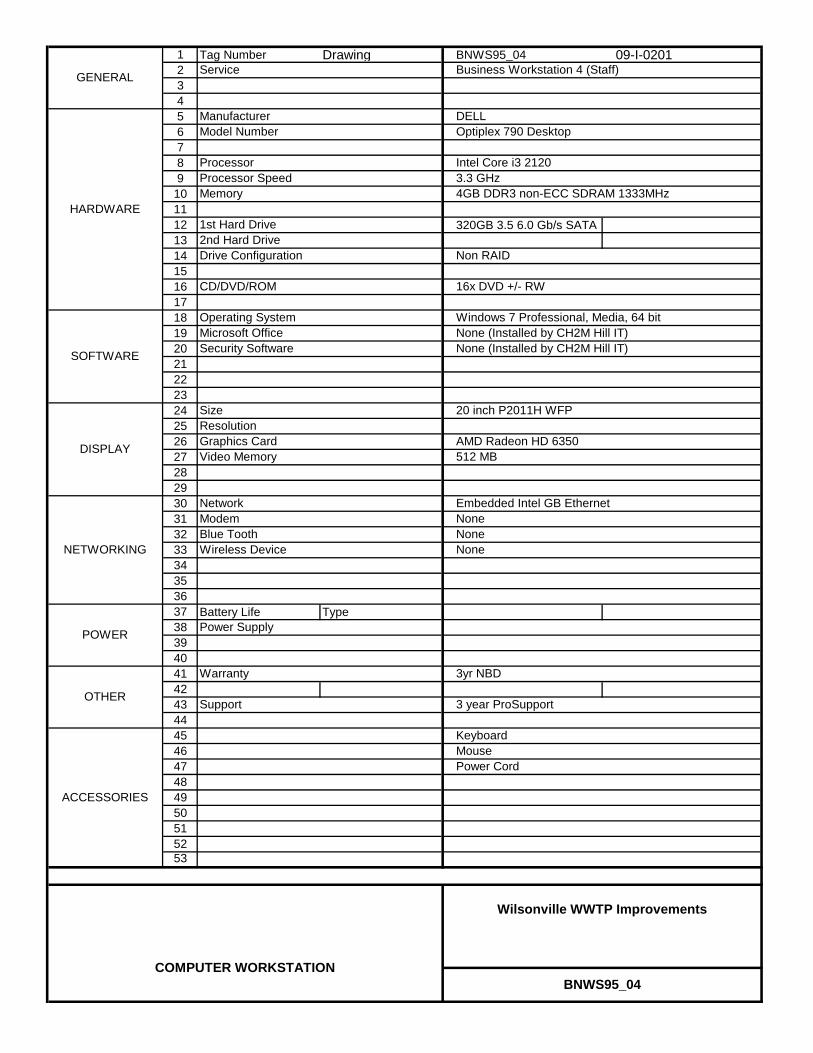
1 Tag Number Drawing BNWS95_04 09-I-020123456789
101112 320GB 3.5 6.0 Gb/s SATA 13141516171819202122232425262728293031323334353637 Battery Life Type38394041424344454647484950515253
BNWS95_04
Wilsonville WWTP Improvements
COMPUTER WORKSTATION
DISPLAY
SizeResolutionGraphics CardVideo Memory
Power Supply
Support
NoneModemBlue Tooth None
ACCESSORIES
Service
Manufacturer
SOFTWARE
Embedded Intel GB Ethernet
KeyboardMousePower Cord
3yr NBD
3 year ProSupportOTHER
Warranty
1st Hard Drive2nd Hard Drive
Business Workstation 4 (Staff)
DELL
Operating System Windows 7 Professional, Media, 64 bit
GENERAL
HARDWARE
NETWORKING
POWER
Microsoft OfficeSecurity Software
Processor SpeedMemory
3.3 GHz4GB DDR3 non-ECC SDRAM 1333MHz
None (Installed by CH2M Hill IT)None (Installed by CH2M Hill IT)
Optiplex 790 DesktopModel Number
Processor Intel Core i3 2120
512 MB
Wireless Device None
Drive Configuration
CD/DVD/ROM
Non RAID
16x DVD +/- RW
AMD Radeon HD 6350
20 inch P2011H WFP
Network

1 Tag Number Drawing BNWS95_05 09-I-020123456789
101112 320GB 3.5 6.0 Gb/s SATA 13141516171819202122232425262728293031323334353637 Battery Life Type38394041424344454647484950515253
BNWS95_05
Wilsonville WWTP Improvements
COMPUTER WORKSTATION
DISPLAY
SizeResolutionGraphics CardVideo Memory
Power Supply
Support
NoneModemBlue Tooth None
ACCESSORIES
Service
Manufacturer
SOFTWARE
Embedded Intel GB Ethernet
KeyboardMousePower Cord
3yr NBD
3 year ProSupportOTHER
Warranty
1st Hard Drive2nd Hard Drive
Business Workstation 5 (Staff)
DELL
Operating System Windows 7 Professional, Media, 64 bit
GENERAL
HARDWARE
NETWORKING
POWER
Microsoft OfficeSecurity Software
Processor SpeedMemory
3.3 GHz4GB DDR3 non-ECC SDRAM 1333MHz
None (Installed by CH2M Hill IT)None (Installed by CH2M Hill IT)
Optiplex 790 DesktopModel Number
Processor Intel Core i3 2120
512 MB
Wireless Device None
Drive Configuration
CD/DVD/ROM
Non RAID
16x DVD +/- RW
AMD Radeon HD 6350
20 inch P2011H WFP
Network

1 Tag Number Drawing BNWS95_06 09-I-020123456789
101112 320GB 3.5 6.0 Gb/s SATA 13141516171819202122232425262728293031323334353637 Battery Life Type38394041424344454647484950515253
Network
512 MB
Wireless Device None
Drive Configuration
CD/DVD/ROM
Non RAID
16x DVD +/- RW
AMD Radeon HD 6350
20 inch P2011H WFP
3.3 GHz4GB DDR3 non-ECC SDRAM 1333MHz
None (Installed by CH2M Hill IT)None (Installed by CH2M Hill IT)
Optiplex 790 DesktopModel Number
Processor Intel Core i3 2120
OTHER
Warranty
1st Hard Drive2nd Hard Drive
Business Workstation 6 (Lab)
DELL
Operating System Windows 7 Professional, Media, 64 bit
GENERAL
HARDWARE
NETWORKING
POWER
Microsoft OfficeSecurity Software
Processor SpeedMemory
ACCESSORIES
Service
Manufacturer
SOFTWARE
Embedded Intel GB Ethernet
KeyboardMousePower Cord
3yr NBD
3 year ProSupport
BNWS95_06
Wilsonville WWTP Improvements
COMPUTER WORKSTATION
DISPLAY
SizeResolutionGraphics CardVideo Memory
Power Supply
Support
NoneModemBlue Tooth None

1 Tag Number Drawing CNWS95_01 09-I-020123456789
101112 320GB 3.5 3.0 Gb/s SATA 13141516171819202122232425262728293031323334353637 Battery Life Type38394041424344454647484950515253
CNWS95_01
Wilsonville WWTP Improvements
COMPUTER WORKSTATION
DISPLAY
SizeResolutionGraphics CardVideo Memory
Power Supply
Support
NoneModemBlue Tooth None
ACCESSORIES
Service
Manufacturer
SOFTWARE
Broadcom NetXtreme Gbit PCI Express
KeyboardMousePower Cord
3yr NBD
5 year ProSupportOTHER
Warranty
1st Hard Drive2nd Hard Drive
SCADA Workstation 1 (Control Room)
DELL
Operating System Windows 7 Professional, Media, 64 bit
GENERAL
HARDWARE
NETWORKING
POWER
Microsoft OfficeSecurity Software
Processor SpeedMemory
2.53 Ghz12GB DDR3 ECC SDRAM 1333MHz, 3X4GB
None (Installed by CH2M Hill IT)None (Installed by CH2M Hill IT)
Precision T3500 MinitowerModel Number
Processor Dual Core Xeon W3505
512 MB
Wireless Device None
Drive Configuration
CD/DVD/ROM
Non RAID
16X DVD +/- RW
Nvidea Quadro NVS 420, 4 Mon
Dell Ultrasharp U2410 24 inch wide monitor1920 x 1080
Video CordRecovery MediaMonitor mounted speaker bar
Network
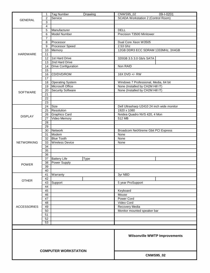
1 Tag Number Drawing CNWS95_02 09-I-020123456789
101112 320GB 3.5 3.0 Gb/s SATA 13141516171819202122232425262728293031323334353637 Battery Life Type38394041424344454647484950515253
CNWS95_02
Wilsonville WWTP Improvements
COMPUTER WORKSTATION
DISPLAY
SizeResolutionGraphics CardVideo Memory
Power Supply
Support
NoneModemBlue Tooth None
ACCESSORIES
Service
Manufacturer
SOFTWARE
Broadcom NetXtreme Gbit PCI Express
KeyboardMousePower Cord
3yr NBD
5 year ProSupportOTHER
Warranty
1st Hard Drive2nd Hard Drive
SCADA Workstation 2 (Control Room)
DELL
Operating System Windows 7 Professional, Media, 64 bit
GENERAL
HARDWARE
NETWORKING
POWER
Microsoft OfficeSecurity Software
Processor SpeedMemory
2.53 Ghz12GB DDR3 ECC SDRAM 1333MHz, 3X4GB
None (Installed by CH2M Hill IT)None (Installed by CH2M Hill IT)
Precision T3500 MinitowerModel Number
Processor Dual Core Xeon W3505
512 MB
Wireless Device None
Drive Configuration
CD/DVD/ROM
Non RAID
16X DVD +/- RW
Nvidea Quadro NVS 420, 4 Mon
Dell Ultrasharp U2410 24 inch wide monitor1920 x 1080
Video CordRecovery MediaMonitor mounted speaker bar
Network
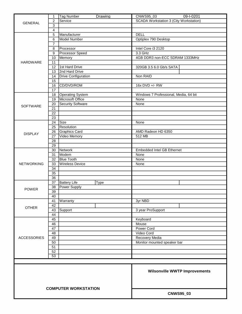
1 Tag Number Drawing CNWS95_03 09-I-020123456789
101112 320GB 3.5 6.0 Gb/s SATA 13141516171819202122232425262728293031323334353637 Battery Life Type38394041424344454647484950515253
Video CordRecovery MediaMonitor mounted speaker bar
Network
512 MB
Wireless Device None
Drive Configuration
CD/DVD/ROM
Non RAID
16x DVD +/- RW
AMD Radeon HD 6350
None
3.3 GHz4GB DDR3 non-ECC SDRAM 1333MHz
NoneNone
Optiplex 790 DesktopModel Number
Processor Intel Core i3 2120
OTHER
Warranty
1st Hard Drive2nd Hard Drive
SCADA Workstation 3 (City Workstation)
DELL
Operating System Windows 7 Professional, Media, 64 bit
GENERAL
HARDWARE
NETWORKING
POWER
Microsoft OfficeSecurity Software
Processor SpeedMemory
ACCESSORIES
Service
Manufacturer
SOFTWARE
Embedded Intel GB Ethernet
KeyboardMousePower Cord
3yr NBD
3 year ProSupport
CNWS95_03
Wilsonville WWTP Improvements
COMPUTER WORKSTATION
DISPLAY
SizeResolutionGraphics CardVideo Memory
Power Supply
Support
NoneModemBlue Tooth None

1 Tag Number Drawing OIT10_01 09-I-020123456789
101112131415 Dimensions Weight 2U x 17" depth1617181920212223242526272829 Dimensions Weight 557 x 362 x 65 WHD 8.6 kgs303132333435363738394041424344454647484950515253
Spare drive bay
Network
None
19" rack mount with slide rails
USB Ports Minimum 2
Panel Mount, Nema 4, Touch Screen
21.5"1920 x 1080
na
TCS-025-01889-001Model Number
Processor XEON E3-1255 CPU
160 GB SATA MLC Solid State Drive
GENERAL
HARDWARE
NETWORKING
Headworks Building Operator Terminal
Total Control Solutions
Windows 7 Professional, 64 bit
3.1 GHz or faster8 GB DDR3 ECC Memory
Service
Manufacturer
TCS-005-01778
Wireless Device
Mounting
Processor SpeedMemory
1st Hard DrivePCI Slots
Operating System
SOFTWARE
KeyboardMouse
GB Ethernet
NoneNonePower Cord
32 to 122 deg F
OTHER
Operating Temperature
POWER
OIT10_01
Wilsonville WWTP Improvements
OPERATOR TERMINAL
DISPLAY
SizeResolutionTypeManufacturerModel Number
Power Supply
NoneModemSerial 4 x RS-232
500 watt 110/220 VAC
ACCESSORIES
Total Control Solutions

1 Tag Number Drawing OIT40_01 09-I-020123456789
101112131415 Dimensions Weight 2U x 17" depth1617181920212223242526272829 Dimensions Weight 557 x 362 x 65 WHD 8.6 kgs303132333435363738394041424344454647484950515253
OIT40_01
Wilsonville WWTP Improvements
OPERATOR TERMINAL
DISPLAY
SizeResolutionTypeManufacturerModel Number
Power Supply
NoneModemSerial 4 x RS-232
500 watt 110/220 VAC
ACCESSORIES
Total Control Solutions
SOFTWARE
KeyboardMouse
GB Ethernet
NoneNonePower Cord
32 to 122 deg F
OTHER
Operating Temperature
POWER
Mounting
Processor SpeedMemory
1st Hard DrivePCI Slots
Operating System
TCS-025-01889-001Model Number
Processor XEON E3-1255 CPU
160 GB SATA MLC Solid State Drive
GENERAL
HARDWARE
NETWORKING
Process Gallery Operator Terminal
Total Control Solutions
Windows 7 Professional, 64 bit
3.1 GHz or faster8 GB DDR3 ECC Memory
Service
Manufacturer
TCS-005-01778
Wireless Device None
19" rack mount with slide rails
USB Ports Minimum 2
Panel Mount, Nema 4, Touch Screen
21.5"1920 x 1080
na
Spare drive bay
Network

1 Tag Number Drawing OIT40_03 09-I-020123456789
101112131415 Dimensions Weight1617181920212223242526272829 Dimensions Weight 557 x 362 x 65 WHD 8.6 kgs303132333435363738394041424344454647484950515253
Network
USB Ports
Panel Mount, Nema 4, Touch Screen
21.5"1920 x 1080
Model Number
Processor
GENERAL
HARDWARE
NETWORKING
GBT Room Operator Terminal
Total Control Solutions
Service
Manufacturer
TCS-005-01778
Wireless Device
Mounting
Processor SpeedMemory
1st Hard DrivePCI Slots
Operating System
SOFTWARE
KeyboardMouse
NoneNonePower Cord
32 to 122 deg F
OTHER
Operating Temperature
POWER
OIT40_03
Wilsonville WWTP Improvements
OPERATOR TERMINAL
DISPLAY
SizeResolutionTypeManufacturerModel Number
Power Supply
ModemSerial
ACCESSORIES
Total Control Solutions
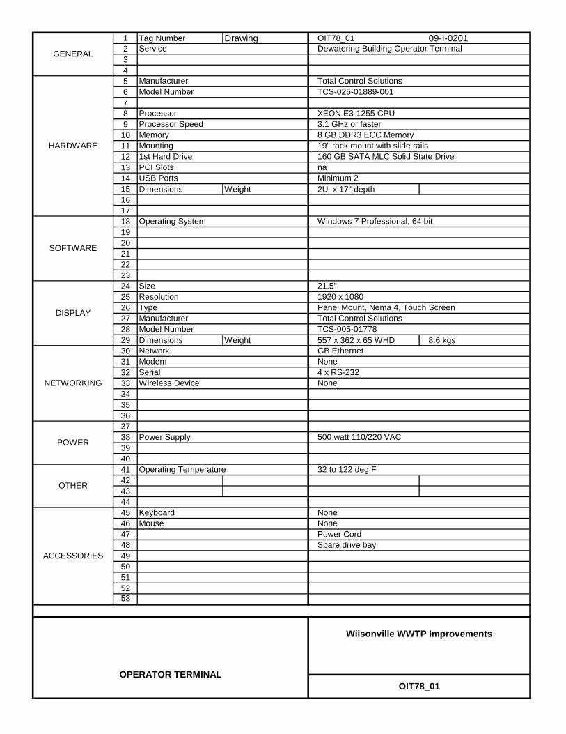
1 Tag Number Drawing OIT78_01 09-I-020123456789
101112131415 Dimensions Weight 2U x 17" depth1617181920212223242526272829 Dimensions Weight 557 x 362 x 65 WHD 8.6 kgs303132333435363738394041424344454647484950515253
OIT78_01
Wilsonville WWTP Improvements
OPERATOR TERMINAL
DISPLAY
SizeResolutionTypeManufacturerModel Number
Power Supply
NoneModemSerial 4 x RS-232
500 watt 110/220 VAC
ACCESSORIES
Total Control Solutions
SOFTWARE
KeyboardMouse
GB Ethernet
NoneNonePower Cord
32 to 122 deg F
OTHER
Operating Temperature
POWER
Mounting
Processor SpeedMemory
1st Hard DrivePCI Slots
Operating System
TCS-025-01889-001Model Number
Processor XEON E3-1255 CPU
160 GB SATA MLC Solid State Drive
GENERAL
HARDWARE
NETWORKING
Dewatering Building Operator Terminal
Total Control Solutions
Windows 7 Professional, 64 bit
3.1 GHz or faster8 GB DDR3 ECC Memory
Service
Manufacturer
TCS-005-01778
Wireless Device None
19" rack mount with slide rails
USB Ports Minimum 2
Panel Mount, Nema 4, Touch Screen
21.5"1920 x 1080
na
Spare drive bay
Network

WILSONVILLE WWTP IMPROVEMENTS – DBO
PW/WBG/425034 ETHERNET NETWORK COMPONENTS MARCH 2012 40 92 07 - 1 ©COPYRIGHT 2012 CH2M HILL
SECTION 40 92 07 ETHERNET NETWORK COMPONENTS
PART 1 GENERAL
1.01 WORK OF THIS SECTION
A. This Section gives the requirements for furnishing Ethernet network components and accessories including switches, routers, and firewalls.
1.02 RELATED SECTIONS
A. Related sections include the following:
1. Division 1, General Requirements.
1.03 SUBMITTALS
A. General: In accordance with Section 01 33 00, Submittal Procedures.
B. Action Submittals:
1. Purchase Quotation: Listing of Ethernet network components and accessories to be provided. Include applicable tag numbers and functional names of components.
2. Order Confirmation Summary: Final listing of Ethernet network components and accessories to be provided.
3. Ethernet Components Data Sheets: a. Neat and legible markups of the Ethernet Components Data
Sheets provided in this Section. b. Markup the Ethernet Components Data Sheets to include
complete product information and corrections to reflect all items in the purchase quotation.
C. Informational Submittals:
1. Operation and Maintenance Information: a. In accordance with Section 01 78 23, Operation, Maintenance,
and Asset Data. b. Provide sufficient detail to allow operation, removal, installation,
adjustment, calibration, maintenance and purchasing replacements for Ethernet components.
c. Name, address and telephone number of the Ethernet Supplier’s local service representative.

WILSONVILLE WWTP IMPROVEMENTS – DBO
ETHERNET NETWORK COMPONENTS PW/WBG/425034 40 92 07 - 2 MARCH 2012 ©COPYRIGHT 2012 CH2M HILL
d. Complete list of supplied Ethernet components with full model numbers, including spare parts and test equipment provided.
2. Manufacturer’s Original Copies of Hardware, Software and Installation, Assembly and Operations Manuals for Ethernet components. Manuals shall include the following information: a. General descriptive information covering the basic features. b. Physical description covering layout and installation requirements
and all environmental constraints. c. Functional and operational descriptions covering the procedures
for programming, operation, startup, shutdown, and of the Ethernet equipment and explaining how the various functions are performed.
d. Maintenance procedures covering checkout and troubleshooting: 1) Checkout procedures shall provide the means to verify the
satisfactory operation of equipment. 2) Troubleshooting procedures shall serve as a guide in
determining faulty components. e. Wiring and schematic diagrams. f. Safety considerations relating to operation and maintenance
procedures. 3. Content for Each O&M Manual:
a. Table of Contents. b. Operations procedures. c. Installation requirements and procedures. d. Maintenance requirements and procedures. e. Troubleshooting procedures. f. Internal schematic and wiring diagrams.
4. List of spares, expendables, test equipment and tools provided. 5. List of additional recommended spares, expendables, test equipment,
and tools. Include quantities, unit prices, and total costs.
1.04 DELIVERY, STORAGE, AND HANDLING
A. In accordance with Section 01 61 00, Common Product Requirements.
B. Packaged at the factory prior to shipment to protect each item from damage during shipment and storage. Containers protected against impact, abrasion, corrosion, discoloration and/or other damages. Clearly label contents of each container and provide information on the required storage conditions necessary for the equipment.
C. Notify Engineer of the storage requirements and recommendations for the equipment prior to shipment.

WILSONVILLE WWTP IMPROVEMENTS – DBO
PW/WBG/425034 ETHERNET NETWORK COMPONENTS MARCH 2012 40 92 07 - 3 ©COPYRIGHT 2012 CH2M HILL
D. Prior to shipment, include corrosive inhibitive vapor capsules in shipping containers, and related equipment as recommended by capsule manufacturer.
PART 2 PRODUCTS
2.01 GENERAL
A. Provide components that are listed in the Ethernet Components List in Article Supplements at the end of this Section. Specific component requirements are defined in the Ethernet Components Data Sheets in Article Supplements at the end of this Section.
PART 3 EXECUTION
3.01 SUPPLEMENTS
A. The supplements listed below, following “End of Section,” are part of this Specification.
1. Ethernet Components List. 2. Ethernet Components Data Sheets.
END OF SECTION


WILSONVILLE WWTP IMPROVEMENTS - DBO
ETHERNET COMPONENTS LISTItem Facility Tag No. Description Manufacturer Model Number Remarks
1 10 BNCPP10_01 Headworks Building Business Network Copper Patch Panel 1 Legrand Ortronics OR-PSD66U24HM 24 port2 10 BNSW10_01 Headworks Building Business Network Switch HP Procurve J9624A 24 port3 10 CNSW10_01 Headworks Building Control Network Switch N-Tron 7026TX-AC 26 port4 10 FPP10_01 Headworks Building Business and SCADA Fiber Patch Panel 1 Legrand Ortronics OR-FC02U-P 24 port5 10 IOSW10_01 Headworks Building PLC I/O Network Switch N-Tron 708TX 8 port6 40 BNCPP40_01 Process Gallery Business Network Copper Patch Panel 1 Legrand Ortronics OR-PSD66U24HM 24 port7 40 BNSW40_01 Process Gallery Business Network Switch HP Procurve J9624A 24 port8 40 CNSW40_01 Process Gallery Control Network Switch N-Tron 7026TX-AC 26 port9 40 FPP40_01 Process Gallery Business and SCADA Fiber Patch Panel 1 Legrand Ortronics OR-FC02U-P 42 port10 40 IOSW40_01 Process Gallery PLC I/O Network Switch 1 N-Tron 708TX 8 port11 40 IOSW40_02 Process Gallery PLC I/O Network Switch 2 N-Tron 708TX 8 port12 70 BNSW70_01 UV Business Network Switch N-Tron 7506GX2-SX 6 port13 70 CNPS70_01 UV Area Control Network 24 vdc power supply N-Tron NTPS-24-1.3 din rail mount14 70 CNSW70_01 UV Area Control Network Switch N-Tron 7506GX2-SX 6 port15 70 FPP70_01 UV Area Business and SCADA Fiber Patch Panel 1 Hubbell FTUS2P with FSPSCD6 18 port16 78 BNCPP78_01 Dewatering Building Business Network Copper Patch Panel 1 Legrand Ortronics OR-PSD66U24HM 24 port17 78 BNSW78_01 Dewatering Building Business Network Switch HP Procurve J9624A 24 port18 78 CNSW78 01 Dewatering Building Control Network Switch N-Tron 7026TX-AC 26 port18 78 CNSW78_01 Dewatering Building Control Network Switch N Tron 7026TX AC 26 port19 78 FPP78_01 Dewatering Building Business and SCADA Fiber Patch Panel 1 Legrand Ortronics OR-FC02U-P 24 port20 78 IOSW78_01 Dewatering Building PLC I/O Network Switch N-Tron 708TX 8 port21 95 BNCPP95_01 Operations Building Business Network Copper Patch Panel 1 Legrand Ortronics OR-PSD66U24HM 24 port22 95 BNFW95_01 Operations Building Business Network Firewall Juniper Networks SSG14023 95 BNSW95_01 Operations Building Business Network Switch 1 HP Procurve J9624A 24 port24 95 BNSW95_02 Operations Building Business Network Switch 2 HP Procurve J9624A 24 port25 95 CNCPP95_01 Operations Building Control Network Copper Patch Panel 1 Legrand Ortronics OR-PSD66U24HM 24 port26 95 CNFW95_01 Operations Building Control Network DMZ Firewall Juniper Networks SSG14027 95 CNSW95_01 Operations Building Control Network Switch 1 N-Tron 7026TX-AC 26 port28 95 CNSW95_02 Operations Building Control Network Switch 2 N-Tron 7026TX-AC 26 port29 95 DMZSW95_01 Operations Building DMZ Network Switch HP Procurve J9624A 24 port30 95 FPP95_01 Operations Building Control Network Fiber Patch Panel 1 Legrand Ortronics OR-FC01U-P 24 port31 95 RTPS95_01 Operations Building Router Network Switch Power Supply N-Tron NTPS-24-1.3 din rail mount32 95 RTSW95_01 Operations Building Router Network Switch N-Tron 7506GX2 4 port33 95 RTSW95_01 Operations Building Router Network Switch Rack Mounting Bracket N-Tron URMK din rail to rack mt
PW/WBG/425034 MARCH 2012©COPYRIGHT 2012 CH2M HILL
ETHERNET NETWORK COMPONENTS40 92 07 SUPPLEMENT - 1


Wilsonville WWTP Improvements
ETHERNET COMPONENTS DATA SHEETS
PW/WBG/425034 MARCH 2012 ©COPYRIGHT 2012 CH2M HILL
ETHERNET COMPONENTS40 92 07 SUPPLEMENT

COPPER PATCH PANEL
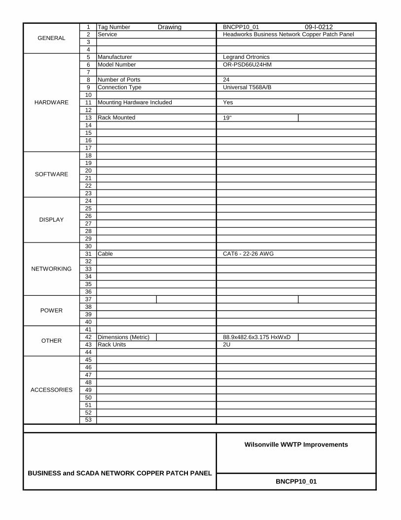
1 Tag Number Drawing BNCPP10_01 09-I-021223456789
10111213 19"1415161718192021222324252627282930313233343536373839404142 Dimensions (Metric) 88.9x482.6x3.175 HxWxD4344454647484950515253
2U
OR-PSD66U24HMModel Number
Number of Ports 24
GENERAL
HARDWARE
Headworks Business Network Copper Patch Panel
Legrand Ortronics
Universal T568A/B
Service
Manufacturer
Mounting Hardware Included
Connection Type
Rack Mounted
SOFTWARE
Yes
OTHER
NETWORKING
POWER
BNCPP10_01
Wilsonville WWTP Improvements
BUSINESS and SCADA NETWORK COPPER PATCH PANEL
DISPLAY
Rack Units
CAT6 - 22-26 AWGCable
ACCESSORIES
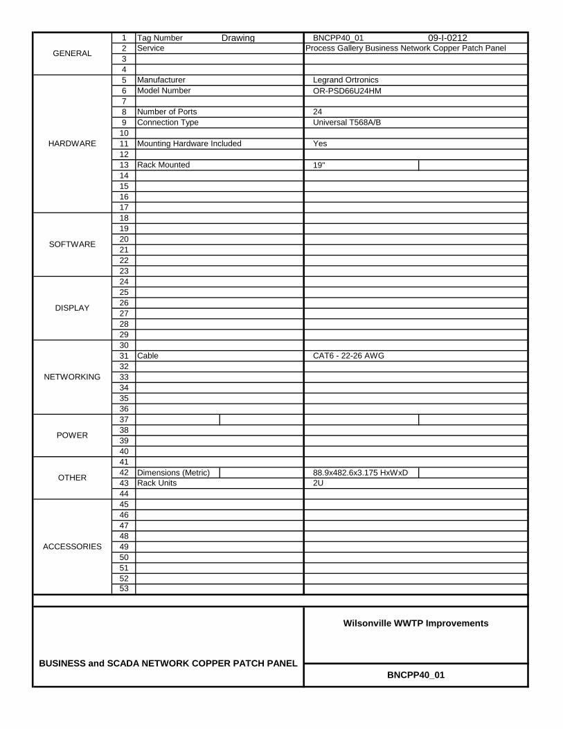
1 Tag Number Drawing BNCPP40_01 09-I-021223456 OR-PSD66U24HM789
10111213 19"1415161718192021222324252627282930313233343536373839404142 Dimensions (Metric) 88.9x482.6x3.175 HxWxD4344454647484950515253
BNCPP40_01
Wilsonville WWTP Improvements
BUSINESS and SCADA NETWORK COPPER PATCH PANEL
DISPLAY
Rack Units
CAT6 - 22-26 AWGCable
ACCESSORIES
OTHER
NETWORKING
POWER
Mounting Hardware Included
Connection Type
Rack Mounted
SOFTWARE
Yes
Model Number
Number of Ports 24
GENERAL
HARDWARE
Process Gallery Business Network Copper Patch Panel
Legrand Ortronics
Universal T568A/B
Service
Manufacturer
2U

1 Tag Number Drawing BNCPP78_01 09-I-021223456 OR-PSD66U24HM789
10111213 19"1415161718192021222324252627282930313233343536373839404142 Dimensions (Metric) 88.9x482.6x3.175 HxWxD4344454647484950515253
BNCPP78_01
Wilsonville WWTP Improvements
BUSINESS and SCADA NETWORK COPPER PATCH PANEL
DISPLAY
Rack Units
CAT6 - 22-26 AWGCable
ACCESSORIES
OTHER
NETWORKING
POWER
Mounting Hardware Included
Connection Type
Rack Mounted
SOFTWARE
Yes
Model Number
Number of Ports 24
GENERAL
HARDWARE
Dewatering Business Network Copper Patch Panel
Legrand Ortronics
Universal T568A/B
Service
Manufacturer
2U

1 Tag Number Drawing BNCPP95_01 09-I-021123456 OR-PSD66U24HM789
10111213 19"1415161718192021222324252627282930313233343536373839404142 Dimensions (Metric) 88.9x482.6x3.175 HxWxD4344454647484950515253
Model Number
Number of Ports 24
GENERAL
HARDWARE
Business Network Copper Patch Panel
Legrand Ortronics
Universal T568A/B
Service
Manufacturer
Mounting Hardware Included
Connection Type
Rack Mounted
SOFTWARE
Yes
OTHER
NETWORKING
POWER
2U
BNCPP95_01
Wilsonville WWTP Improvements
BUSINESS and SCADA NETWORK COPPER PATCH PANEL
DISPLAY
Rack Units
CAT6 - 22-26 AWGCable
ACCESSORIES

1 Tag Number Drawing CNCPP95_01 09-I-021123456 OR-PSD66U24HM789
10111213 19"1415161718192021222324252627282930313233343536373839404142 Dimensions (Metric) 88.9x482.6x3.175 HxWxD4344454647484950515253
Model Number
Number of Ports 24
GENERAL
HARDWARE
Control Network Copper Patch Panel
Legrand Ortronics
Universal T568A/B
Service
Manufacturer
Mounting Hardware Included
Connection Type
Rack Mounted
SOFTWARE
Yes
OTHER
NETWORKING
POWER
2U
CNCPP95_01
Wilsonville WWTP Improvements
BUSINESS and SCADA NETWORK COPPER PATCH PANEL
DISPLAY
Rack Units
CAT6 - 22-26 AWGCable
ACCESSORIES

FIBER PATCH PANEL

1 Tag Number Drawing FPP10_01 09-I-212234567 Adapter Panel Model Number Quantity OR-OFP-LCD12LC 3 - six port panels8 Panel Blank Model Number Quantity OR-HDFP-BLANK 3 - Blank panels9
101112131415161718192021222324252627282930313233343536373839404142 Dimensions (Metric) 89 x 483 x 486 H x W x D4344454647484950515253
FPP10_01
Wilsonville WWTP Improvements
BUSINESS and CONTROL NETWORK FIBER PATCH PANEL
DISPLAY
Rack Units
50/125 micron, MultimodeFiber Type
Mounting
Adapter Type LC, Zirconia Ceramic
SOFTWARE
19" Rack2UOTHER
NETWORKING
ACCESSORIES
POWER
OR-FC02U-PFiber Cabinet Model Number
Six adapter panels
GENERAL
HARDWARE
Headworks Fiber Patch Panel
Legrand Ortronics
Service
Manufacturer
Mounting Hardware Included YesCapacity

1 Tag Number Drawing FPP40_01 09-I-212234567 Adapter Panel Model Number Quantity OR-OFP-LCD12LC 4 - six port panels8 Panel Blank Model Number Quantity OR-HDFP-BLANK 2 - Blank panels9
101112131415161718192021222324252627282930313233343536373839404142 Dimensions (Metric) 89 x 483 x 486 H x W x D4344454647484950515253
FPP40_01
Wilsonville WWTP Improvements
BUSINESS and CONTROL NETWORK FIBER PATCH PANEL
DISPLAY
Rack Units
50/125 micron, MultimodeFiber Type
Mounting
Adapter Type LC, Zirconia Ceramic
SOFTWARE
19" Rack2UOTHER
NETWORKING
ACCESSORIES
POWER
OR-FC02U-PFiber Cabinet Model Number
Six adapter panels
GENERAL
HARDWARE
Process Gallery Fiber Patch Panel
Legrand Ortronics
Service
Manufacturer
Mounting Hardware Included YesCapacity
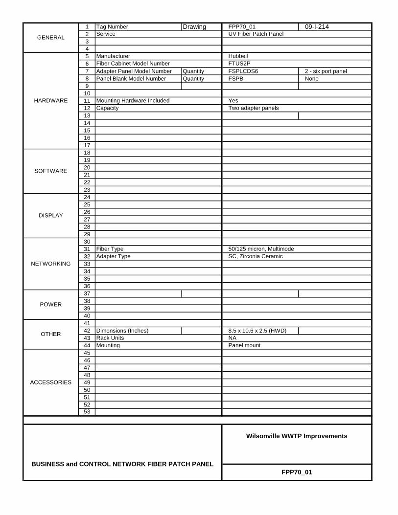
1 Tag Number Drawing FPP70_01 09-I-214234567 Adapter Panel Model Number Quantity FSPLCDS6 2 - six port panel8 Panel Blank Model Number Quantity FSPB None9
101112131415161718192021222324252627282930313233343536373839404142 Dimensions (Inches) 8.5 x 10.6 x 2.5 (HWD)4344454647484950515253
FPP70_01
Wilsonville WWTP Improvements
BUSINESS and CONTROL NETWORK FIBER PATCH PANEL
DISPLAY
Rack Units
50/125 micron, MultimodeFiber Type
Mounting
Adapter Type SC, Zirconia Ceramic
SOFTWARE
Panel mountNAOTHER
NETWORKING
ACCESSORIES
POWER
FTUS2PFiber Cabinet Model Number
Two adapter panels
GENERAL
HARDWARE
UV Fiber Patch Panel
Hubbell
Service
Manufacturer
Mounting Hardware Included YesCapacity

1 Tag Number Drawing FPP78_01 09-I-212234567 Adapter Panel Model Number Quantity OR-OFP-LCD12LC 3 - six port panels8 Panel Blank Model Number Quantity OR-HDFP-BLANK 3 - Blank panels9
101112131415161718192021222324252627282930313233343536373839404142 Dimensions (Metric) 89 x 483 x 486 H x W x D4344454647484950515253
FPP78_01
Wilsonville WWTP Improvements
BUSINESS and CONTROL NETWORK FIBER PATCH PANEL
DISPLAY
Rack Units
50/125 micron, MultimodeFiber Type
Mounting
Adapter Type LC, Zirconia Ceramic
SOFTWARE
19" Rack2UOTHER
NETWORKING
ACCESSORIES
POWER
OR-FC02U-PFiber Cabinet Model Number
Six adapter panels
GENERAL
HARDWARE
Dewatering Fiber Patch Panel
Legrand Ortronics
Service
Manufacturer
Mounting Hardware Included YesCapacity
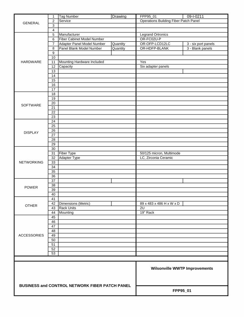
1 Tag Number Drawing FPP95_01 09-I-0211234567 Adapter Panel Model Number Quantity OR-OFP-LCD12LC 3 - six port panels8 Panel Blank Model Number Quantity OR-HDFP-BLANK 3 - Blank panels9
101112131415161718192021222324252627282930313233343536373839404142 Dimensions (Metric) 89 x 483 x 486 H x W x D4344454647484950515253
FPP95_01
Wilsonville WWTP Improvements
BUSINESS and CONTROL NETWORK FIBER PATCH PANEL
DISPLAY
Rack Units
50/125 micron, MultimodeFiber Type
Mounting
Adapter Type LC, Zirconia Ceramic
SOFTWARE
19" Rack2UOTHER
NETWORKING
ACCESSORIES
POWER
OR-FC02U-PFiber Cabinet Model Number
Six adapter panels
GENERAL
HARDWARE
Operations Building Fiber Patch Panel
Legrand Ortronics
Service
Manufacturer
Mounting Hardware Included YesCapacity

NETWORK FIREWALL

1 Tag Number Drawing BNFW95_01 09-I-020123456789
101112131415161718192021222324252627282930313233343536373839404142 Dimensions Inches Weight 17.5 x 1.8 x 15 10.2 lb4344454647484950515253
Yes, VariousYes, Various
19-inch rack
SSG140Model Number
Number of Ethernet Ports 8
GENERAL
HARDWARE
Business Network Firewall
Juniper Networks
100 Mbps
Service
Manufacturer
Speed
SOFTWARE
Voip
OTHER
NETWORKING
POWER
BNFW95_01
Wilsonville WWTP Improvements
OPERATIONS BLDG BUSINESS NETWORK FIREWALL
Security
Firewall
Power Supply
Mounting
100-240 VAC 50/60 hz 2 A
ACCESSORIES

1 Tag Number Drawing CNFW95_01 09-I-020123456789
101112131415161718192021222324252627282930313233343536373839404142 Dimensions Inches Weight 17.5 x 1.8 x 15 10.2 lb4344454647484950515253
CNFW95_01
Wilsonville WWTP Improvements
CONTROL NETWORK DMZ FIREWALL
Security
Firewall
Power Supply
Mounting
100-240 VAC 50/60 hz 2 A
ACCESSORIES
OTHER
NETWORKING
POWER
Voip
GENERAL
HARDWARE
Control Network DMZ Firewall
Juniper Networks
100 Mbps
Service
Manufacturer
Speed
SOFTWARE
SSG140Model Number
Number of Ethernet Ports 8
Yes, VariousYes, Various
19-inch rack

CONTROL NETWORK POWER SUPPLY
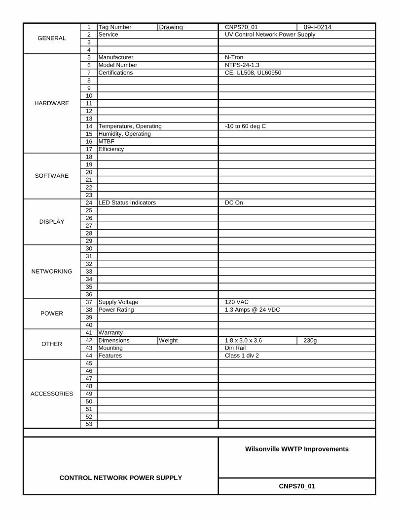
1 Tag Number Drawing CNPS70_01 09-I-021423456789
101112131415161718192021222324252627282930313233343536373839404142 Dimensions Weight 1.8 x 3.0 x 3.6 230g4344454647484950515253
CNPS70_01
Wilsonville WWTP Improvements
CONTROL NETWORK POWER SUPPLY
DISPLAY
Power Rating
MountingFeatures
1.3 Amps @ 24 VDC
ACCESSORIES
Warranty
SOFTWARE
Class 1 div 2Din RailOTHER
Supply Voltage 120 VAC
NETWORKING
POWER
Certifications
Efficiency
Temperature, Operating
MTBF
NTPS-24-1.3Model Number
GENERAL
HARDWARE
UV Control Network Power Supply
N-Tron
CE, UL508, UL60950
Service
Manufacturer
LED Status Indicators
-10 to 60 deg CHumidity, Operating
DC On
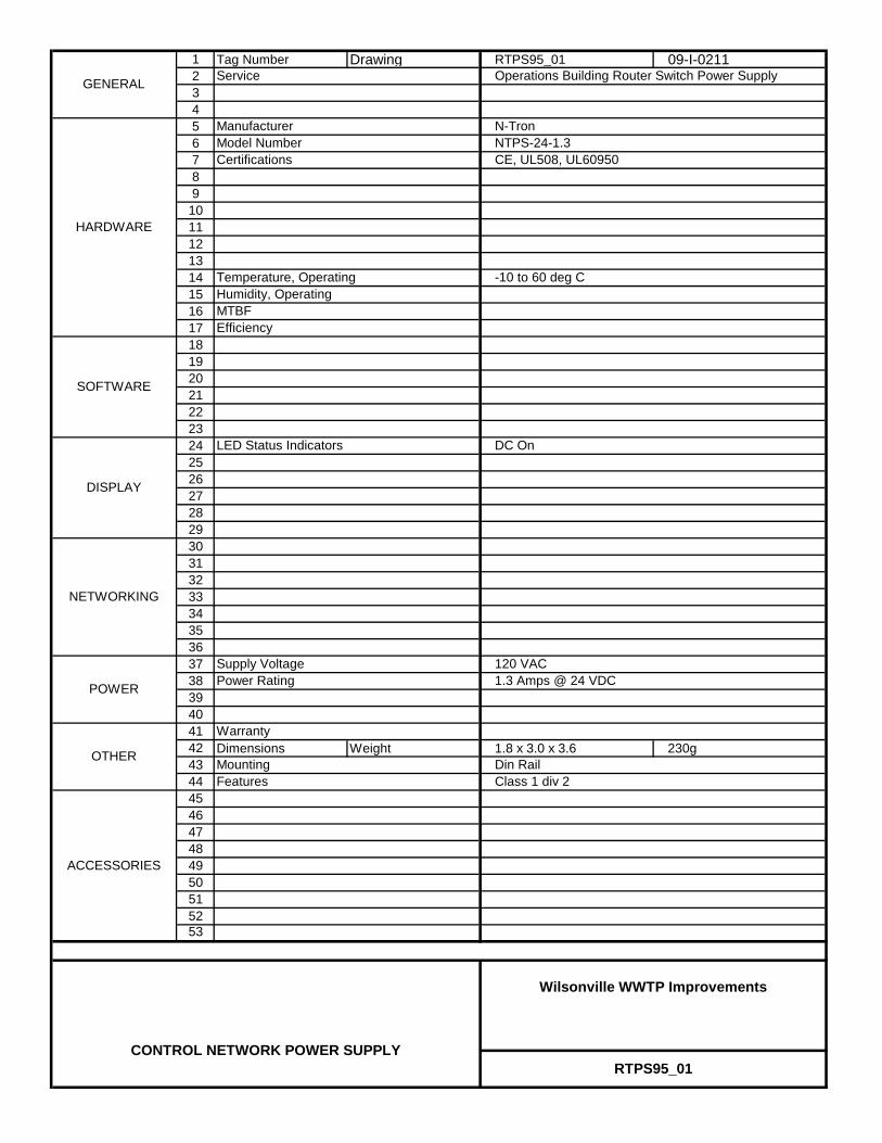
1 Tag Number Drawing RTPS95_01 09-I-021123456789
101112131415161718192021222324252627282930313233343536373839404142 Dimensions Weight 1.8 x 3.0 x 3.6 230g4344454647484950515253
LED Status Indicators
-10 to 60 deg CHumidity, Operating
DC On
NTPS-24-1.3Model Number
GENERAL
HARDWARE
Operations Building Router Switch Power Supply
N-Tron
CE, UL508, UL60950
Service
Manufacturer
Certifications
Efficiency
Temperature, Operating
MTBF
SOFTWARE
Class 1 div 2Din RailOTHER
Supply Voltage 120 VAC
NETWORKING
POWER
RTPS95_01
Wilsonville WWTP Improvements
CONTROL NETWORK POWER SUPPLY
DISPLAY
Power Rating
MountingFeatures
1.3 Amps @ 24 VDC
ACCESSORIES
Warranty

NETWORK SWITCH
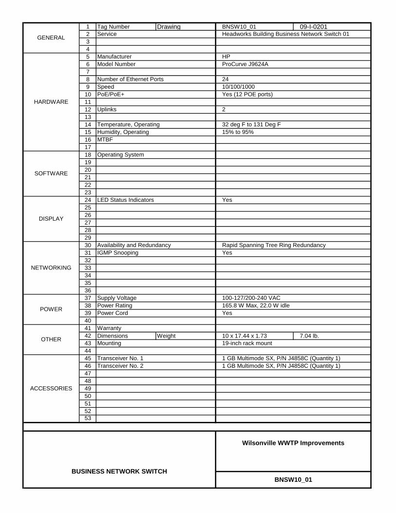
1 Tag Number Drawing BNSW10_01 09-I-020123456789
101112131415161718192021222324252627282930313233343536373839404142 Dimensions Weight 10 x 17.44 x 1.73 7.04 lb.4344454647484950515253
BNSW10_01
Wilsonville WWTP Improvements
BUSINESS NETWORK SWITCH
DISPLAY
Power Rating
Mounting
1 GB Multimode SX, P/N J4858C (Quantity 1)Transceiver No. 2
165.8 W Max, 22.0 W idle
ACCESSORIES
Warranty
SOFTWARE
Transceiver No. 1
Rapid Spanning Tree Ring Redundancy
1 GB Multimode SX, P/N J4858C (Quantity 1)
19-inch rack mountOTHER
IGMP Snooping Yes
Supply Voltage 100-127/200-240 VAC
NETWORKING
POWER
SpeedPoE/PoE+
Uplinks
Operating System
Temperature, Operating
MTBF
ProCurve J9624AModel Number
Number of Ethernet Ports 24
2
GENERAL
HARDWARE
Headworks Building Business Network Switch 01
HP
10/100/1000Yes (12 POE ports)
Service
Manufacturer
Power Cord Yes
LED Status Indicators
32 deg F to 131 Deg F15% to 95%Humidity, Operating
Yes
Availability and Redundancy

1 Tag Number Drawing BNSW40_01 09-I-020123456789
101112131415161718192021222324252627282930313233343536373839404142 Dimensions Weight 10 x 17.44 x 1.73 7.04 lb.4344454647484950515253
BNSW40_01
Wilsonville WWTP Improvements
BUSINESS NETWORK SWITCH
DISPLAY
Power Rating
Mounting
1 GB Multimode SX, P/N J4858C (Quantity 1)Transceiver No. 2
165.8 W Max, 22.0 W idle
ACCESSORIES
Warranty
SOFTWARE
Transceiver No. 1
Rapid Spanning Tree Ring Redundancy
1 GB Multimode SX, P/N J4858C (Quantity 1)
19-inch rack mountOTHER
IGMP Snooping Yes
Supply Voltage 100-127/200-240 VAC
NETWORKING
POWER
SpeedPoE/PoE+
Uplinks
Operating System
Temperature, Operating
MTBF
ProCurve J9624AModel Number
Number of Ethernet Ports 24
2
GENERAL
HARDWARE
Process Gallery Business Network Switch 01
HP
10/100/1000Yes (12 POE ports)
Service
Manufacturer
Power Cord Yes
LED Status Indicators
32 deg F to 131 Deg F15% to 95%Humidity, Operating
Yes
Availability and Redundancy
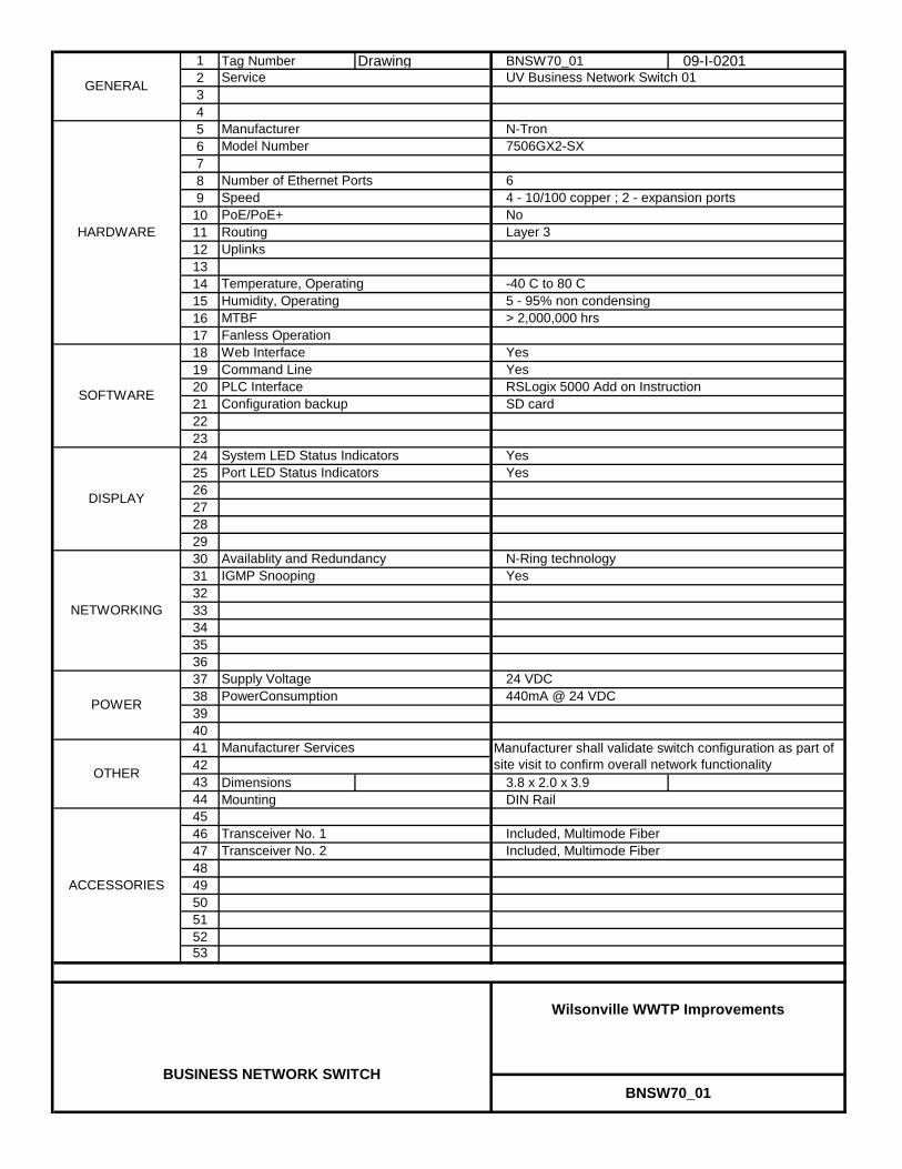
1 Tag Number Drawing BNSW70_01 09-I-020123456789
10111213141516171819202122232425262728293031323334353637383940414243 Dimensions 3.8 x 2.0 x 3.944 Mounting DIN Rail454647484950515253
Availablity and Redundancy
YesYes
Included, Multimode Fiber
Manufacturer shall validate switch configuration as part of site visit to confirm overall network functionality
7506GX2-SXModel Number
Number of Ethernet Ports 6
SD cardConfiguration backup
Temperature, Operating
MTBF
GENERAL
HARDWARE
UV Business Network Switch 01
N-Tron
Yes
4 - 10/100 copper ; 2 - expansion portsNo
Service
Manufacturer
Routing
SpeedPoE/PoE+
Uplinks
Web InterfaceFanless Operation
SOFTWARE
Layer 3
System LED Status Indicators
-40 C to 80 C5 - 95% non condensing> 2,000,000 hrs
Humidity, Operating
Transceiver No. 1Transceiver No. 2
N-Ring technology
POWER
Command LinePLC Interface
24 VDCSupply Voltage
Yes
YesRSLogix 5000 Add on Instruction
BNSW70_01
Wilsonville WWTP Improvements
BUSINESS NETWORK SWITCH
DISPLAY
Port LED Status Indicators
PowerConsumption
Included, Multimode Fiber
IGMP Snooping
440mA @ 24 VDC
ACCESSORIES
Manufacturer Services
OTHER
NETWORKING

1 Tag Number Drawing BNSW78_01 09-I-020123456789
101112131415161718192021222324252627282930313233343536373839404142 Dimensions Weight 10 x 17.44 x 1.73 7.04 lb.4344454647484950515253
BNSW78_01
Wilsonville WWTP Improvements
BUSINESS NETWORK SWITCH
DISPLAY
Power Rating
Mounting
1 GB Multimode SX, P/N J4858C (Quantity 1)Transceiver No. 2
165.8 W Max, 22.0 W idle
ACCESSORIES
Warranty
SOFTWARE
Transceiver No. 1
Rapid Spanning Tree Ring Redundancy
1 GB Multimode SX, P/N J4858C (Quantity 1)
19-inch rack mountOTHER
IGMP Snooping Yes
Supply Voltage 100-127/200-240 VAC
NETWORKING
POWER
SpeedPoE/PoE+
Uplinks
Operating System
Temperature, Operating
MTBF
ProCurve J9624AModel Number
Number of Ethernet Ports 24
2
GENERAL
HARDWARE
Dewatering Building Business Network Switch 01
HP
10/100/1000Yes (12 POE ports)
Service
Manufacturer
Power Cord Yes
LED Status Indicators
32 deg F to 131 Deg F15% to 95%Humidity, Operating
Yes
Availability and Redundancy

1 Tag Number Drawing BNSW95_01 09-I-020123456789
101112131415161718192021222324252627282930313233343536373839404142 Dimensions Weight 10 x 17.44 x 1.73 7.04 lb.4344454647484950515253
BNSW95_01
Wilsonville WWTP Improvements
BUSINESS NETWORK SWITCH
DISPLAY
Power Rating
Mounting
1 GB Multimode SX, P/N J4858C (Quantity 1)Transceiver No. 2
165.8 W Max, 22.0 W idle
ACCESSORIES
Warranty
SOFTWARE
Transceiver No. 1
Rapid Spanning Tree Ring Redundancy
1 GB Multimode SX, P/N J4858C (Quantity 1)
19-inch rack mountOTHER
IGMP Snooping Yes
Supply Voltage 100-127/200-240 VAC
NETWORKING
POWER
SpeedPoE/PoE+
Uplinks
Operating System
Temperature, Operating
MTBF
ProCurve J9624AModel Number
Number of Ethernet Ports 24
2
GENERAL
HARDWARE
Operations Building Business Network Switch 01
HP
10/100/1000Yes (12 POE ports)
Service
Manufacturer
Power Cord Yes
LED Status Indicators
32 deg F to 131 Deg F15% to 95%Humidity, Operating
Yes
Availability and Redundancy

1 Tag Number Drawing BNSW95_02 09-I-020123456789
101112131415161718192021222324252627282930313233343536373839404142 Dimensions Weight 10 x 17.44 x 1.73 7.04 lb.4344454647484950515253
BNSW95_02
Wilsonville WWTP Improvements
BUSINESS NETWORK SWITCH
DISPLAY
Power Rating
Mounting
1 GB Multimode SX, P/N J4858C (Quantity 1)Transceiver No. 2
165.8 W Max, 22.0 W idle
ACCESSORIES
Warranty
SOFTWARE
Transceiver No. 1
Rapid Spanning Tree Ring Redundancy
1 GB Multimode SX, P/N J4858C (Quantity 1)
19-inch rack mountOTHER
IGMP Snooping Yes
Supply Voltage 100-127/200-240 VAC
NETWORKING
POWER
SpeedPoE/PoE+
Uplinks
Operating System
Temperature, Operating
MTBF
ProCurve J9624AModel Number
Number of Ethernet Ports 24
2
GENERAL
HARDWARE
Operations Building Business Network Switch 02
HP
10/100/1000Yes (12 POE ports)
Service
Manufacturer
Power Cord Yes
LED Status Indicators
32 deg F to 131 Deg F15% to 95%Humidity, Operating
Yes
Availability and Redundancy

1 Tag Number Drawing CNSW10_01 09-I-020123456789
10111213141516171819202122232425262728293031323334353637383940414243 Dimensions 1U44 Mounting 19 inch rack454647484950515253
Availablity and Redundancy
YesYes
1000BaseSX multimode fiber P/N NTSFP-SX
Manufacturer shall validate switch configuration as part of site visit to confirm overall network functionality
7026TX-ACModel Number
Number of Ethernet Ports 26
SD card
2 Dual-Purpose One Gigabit Ethernet SFP ports
Configuration backup
Temperature, Operating
MTBF
GENERAL
HARDWARE
Headworks Building Control Network Switch 01
N-Tron
Yes
24 - 10/100 copper ; 2 - 1000 fiberNo
Service
Manufacturer
Routing
SpeedPoE/PoE+
Uplinks
Web InterfaceFanless Operation
SOFTWARE
Layer 3
System LED Status Indicators
-40 C to 80 C5 - 95% non condensing> 1,000,000 hrs
Humidity, Operating
Transceiver No. 1Transceiver No. 2
N-Ring technology
POWER
Command LinePLC Interface
120 VACSupply Voltage
Yes
YesRSLogix 5000 Add on Instruction
CNSW10_01
Wilsonville WWTP Improvements
CONTROL NETWORK SWITCH
DISPLAY
Port LED Status Indicators
PowerConsumption
1000BaseSX multimode fiber P/N NTSFP-SX
IGMP Snooping
215ma @ 120 vac
ACCESSORIES
Manufacturer Services
OTHER
NETWORKING

1 Tag Number Drawing CNSW40_01 09-I-020123456789
10111213141516171819202122232425262728293031323334353637383940414243 Dimensions 1U44 Mounting 19 inch rack454647484950515253
DISPLAY
Port LED Status Indicators
PowerConsumption
1000BaseSX multimode fiber P/N NTSFP-SX
IGMP Snooping
215ma @ 120 vac
ACCESSORIES
Manufacturer Services
OTHER
NETWORKING
Transceiver No. 1Transceiver No. 2
SOFTWARE
Command LinePLC Interface
YesRSLogix 5000 Add on InstructionSD cardConfiguration backup
Layer 3
-40 C to 80 C5 - 95% non condensing> 1,000,000 hrs
Humidity, Operating
CNSW40_01
Wilsonville WWTP Improvements
CONTROL NETWORK SWITCH
Availablity and Redundancy
YesYes
POWER
System LED Status Indicators
N-Ring technology
120 VACSupply Voltage
Yes
GENERAL Process Gallery Control Network Switch 01Service
7026TX-ACModel Number
HARDWARE
N-Tron
24 - 10/100 copper ; 2 - 1000 fiberNo
Manufacturer
Routing
SpeedPoE/PoE+
Uplinks
Fanless Operation
Number of Ethernet Ports 26
2 Dual-Purpose One Gigabit Ethernet SFP ports
Temperature, Operating
MTBF
1000BaseSX multimode fiber P/N NTSFP-SX
Manufacturer shall validate switch configuration as part of site visit to confirm overall network functionality
YesWeb Interface
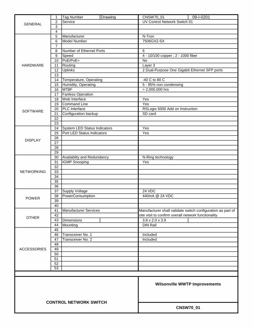
1 Tag Number Drawing CNSW70_01 09-I-020123456789
10111213141516171819202122232425262728293031323334353637383940414243 Dimensions 3.8 x 2.0 x 3.944 Mounting DIN Rail454647484950515253
Number of Ethernet Ports 6
2 Dual-Purpose One Gigabit Ethernet SFP ports
Temperature, Operating
MTBF
Included
Manufacturer shall validate switch configuration as part of site visit to confirm overall network functionality
GENERAL UV Control Network Switch 01Service
7506GX2-SXModel Number
CNSW70_01
Wilsonville WWTP Improvements
CONTROL NETWORK SWITCH
Availablity and Redundancy
YesYes
POWER
HARDWARE
N-Tron
Yes
4 - 10/100 copper ; 2 - 1000 fiberNo
Manufacturer
Routing
SpeedPoE/PoE+
Uplinks
Web InterfaceFanless Operation
SOFTWARE
Command LinePLC Interface
YesRSLogix 5000 Add on InstructionSD cardConfiguration backup
Layer 3
System LED Status Indicators
-40 C to 80 C5 - 95% non condensing> 2,000,000 hrs
Humidity, Operating
N-Ring technology
24 VDCSupply Voltage
Yes
Transceiver No. 1Transceiver No. 2
DISPLAY
Port LED Status Indicators
PowerConsumption
Included
IGMP Snooping
440mA @ 24 VDC
ACCESSORIES
Manufacturer Services
OTHER
NETWORKING

1 Tag Number Drawing CNSW78_01 09-I-020123456789
10111213141516171819202122232425262728293031323334353637383940414243 Dimensions 1U44 Mounting 19 inch rack454647484950515253
DISPLAY
Port LED Status Indicators
PowerConsumption
1000BaseSX multimode fiber P/N NTSFP-SX
IGMP Snooping
215ma @ 120 vac
ACCESSORIES
Manufacturer Services
OTHER
NETWORKING
Transceiver No. 1Transceiver No. 2
SOFTWARE
Command LinePLC Interface
YesRSLogix 5000 Add on InstructionSD cardConfiguration backup
Layer 3
-40 C to 80 C5 - 95% non condensing> 1,000,000 hrs
Humidity, Operating
CNSW78_01
Wilsonville WWTP Improvements
CONTROL NETWORK SWITCH
Availablity and Redundancy
YesYes
POWER
System LED Status Indicators
N-Ring technology
120 VACSupply Voltage
Yes
GENERAL Dewatering/Drying Control Network Switch 01Service
7026TX-ACModel Number
HARDWARE
N-Tron
24 - 10/100 copper ; 2 - 1000 fiberNo
Manufacturer
Routing
SpeedPoE/PoE+
Uplinks
Fanless Operation
Number of Ethernet Ports 26
2 Dual-Purpose One Gigabit Ethernet SFP ports
Temperature, Operating
MTBF
1000BaseSX multimode fiber P/N NTSFP-SX
Manufacturer shall validate switch configuration as part of site visit to confirm overall network functionality
YesWeb Interface

1 Tag Number Drawing CNSW95_01 09-I-020123456789
10111213141516171819202122232425262728293031323334353637383940414243 Dimensions 1U44 Mounting 19 inch rack454647484950515253
DISPLAY
Port LED Status Indicators
PowerConsumption
1000BaseSX multimode fiber P/N NTSFP-SX
IGMP Snooping
215ma @ 120 vac
ACCESSORIES
Manufacturer Services
OTHER
NETWORKING
Transceiver No. 1Transceiver No. 2
SOFTWARE
Command LinePLC Interface
YesRSLogix 5000 Add on InstructionSD cardConfiguration backup
Layer 3
-40 C to 80 C5 - 95% non condensing> 1,000,000 hrs
Humidity, Operating
CNSW95_01
Wilsonville WWTP Improvements
CONTROL NETWORK SWITCH
Availablity and Redundancy
YesYes
POWER
System LED Status Indicators
N-Ring technology
120 VACSupply Voltage
Yes
GENERAL Operations Building Control Network Switch 01Service
7026TX-ACModel Number
HARDWARE
N-Tron
24 - 10/100 copper ; 2 - 1000 fiberNo
Manufacturer
Routing
SpeedPoE/PoE+
Uplinks
Fanless Operation
Number of Ethernet Ports 26
2 Dual-Purpose One Gigabit Ethernet SFP ports
Temperature, Operating
MTBF
1000BaseSX multimode fiber P/N NTSFP-SX
Manufacturer shall validate switch configuration as part of site visit to confirm overall network functionality
YesWeb Interface
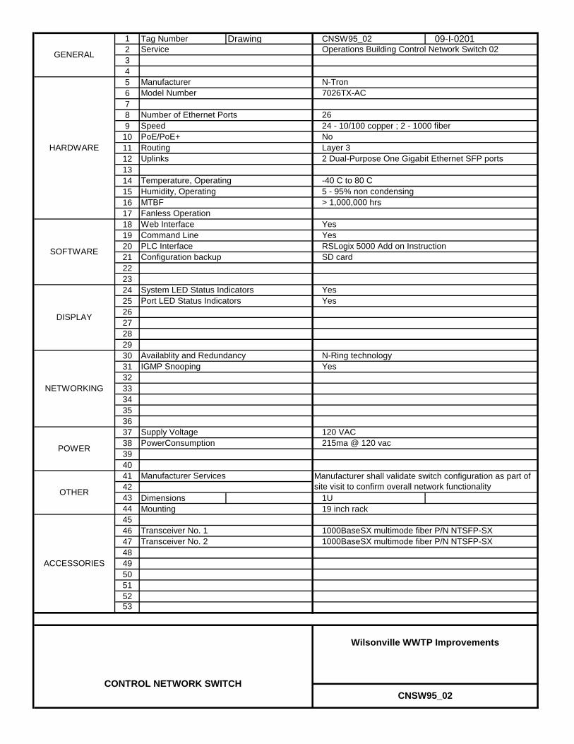
1 Tag Number Drawing CNSW95_02 09-I-020123456789
10111213141516171819202122232425262728293031323334353637383940414243 Dimensions 1U44 Mounting 19 inch rack454647484950515253
1000BaseSX multimode fiber P/N NTSFP-SX
N-Ring technology
1000BaseSX multimode fiber P/N NTSFP-SX
IGMP Snooping
215ma @ 120 vac
ACCESSORIES
Manufacturer Services
OTHER
NETWORKING
Transceiver No. 1Transceiver No. 2
HARDWARE
N-Tron
Yes
24 - 10/100 copper ; 2 - 1000 fiberNo
Manufacturer
Routing
SpeedPoE/PoE+
Uplinks
Web InterfaceFanless Operation
SOFTWARE
Command LinePLC Interface
YesRSLogix 5000 Add on Instruction
Layer 3
7026TX-ACModel Number
Number of Ethernet Ports 26
SD card
2 Dual-Purpose One Gigabit Ethernet SFP ports
Configuration backup
Temperature, Operating
MTBF
-40 C to 80 C5 - 95% non condensing> 1,000,000 hrs
Humidity, Operating
Availablity and Redundancy
YesYes
Manufacturer shall validate switch configuration as part of site visit to confirm overall network functionality
120 VACSupply Voltage
Yes
System LED Status Indicators
CNSW95_02
Wilsonville WWTP Improvements
CONTROL NETWORK SWITCH
GENERAL Operations Building Control Network Switch 02Service
POWER
DISPLAY
Port LED Status Indicators
PowerConsumption

1 Tag Number Drawing DMZSW95_01 09-I-020123456789
101112131415161718192021222324252627282930313233343536373839404142 Dimensions Weight 10 x 17.44 x 1.73 7.04 lb.4344454647484950515253
Availability and Redundancy
Power Cord Yes
LED Status Indicators
32 deg F to 131 Deg F15% to 95%Humidity, Operating
Yes
ProCurve J9624AModel Number
Number of Ethernet Ports 24
2
GENERAL
HARDWARE
Operations Building DMZ Network Switch 1
HP
10/100/1000Yes (12 POE ports)
Service
Manufacturer
SpeedPoE/PoE+
Uplinks
Operating System
Temperature, Operating
MTBF
SOFTWARE
Transceiver No. 1
Rapid Spanning Tree Ring Redundancy
1 GB Multimode SX, P/N J4858C (Quantity 1)
19-inch rack mountOTHER
IGMP Snooping Yes
Supply Voltage 100-127/200-240 VAC
NETWORKING
POWER
DMZSW95_01
Wilsonville WWTP Improvements
BUSINESS NETWORK SWITCH
DISPLAY
Power Rating
Mounting
1 GB Multimode SX, P/N J4858C (Quantity 1)Transceiver No. 2
165.8 W Max, 22.0 W idle
ACCESSORIES
Warranty
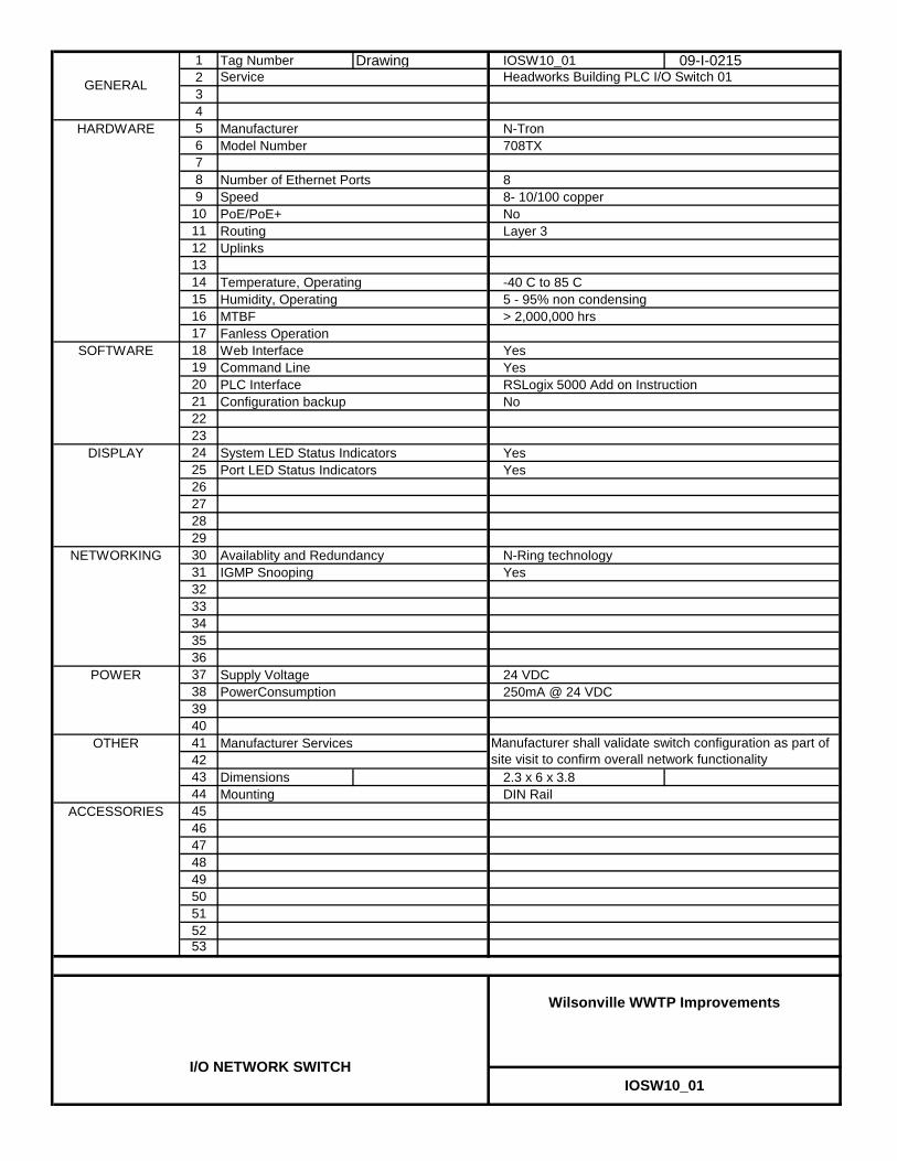
1 Tag Number Drawing IOSW10_01 09-I-0215234
HARDWARE 5 Manufacturer N-Tron6 Model Number 708TX78 Number of Ethernet Ports 89 Speed 8- 10/100 copper
10 PoE/PoE+ No11 Routing Layer 312 Uplinks1314 Temperature, Operating -40 C to 85 C15 Humidity, Operating 5 - 95% non condensing16 MTBF > 2,000,000 hrs17 Fanless Operation
SOFTWARE 18 Web Interface Yes19 Command Line Yes20 PLC Interface RSLogix 5000 Add on Instruction21 Configuration backup No2223
DISPLAY 24 System LED Status Indicators Yes25 Port LED Status Indicators Yes26272829
NETWORKING 30 Availablity and Redundancy N-Ring technology31 IGMP Snooping Yes3233343536
POWER 37 Supply Voltage 24 VDC38 PowerConsumption 250mA @ 24 VDC3940
OTHER 41 Manufacturer Services4243 Dimensions 2.3 x 6 x 3.844 Mounting DIN Rail
ACCESSORIES 454647484950515253
IOSW10_01
Wilsonville WWTP Improvements
I/O NETWORK SWITCH
Manufacturer shall validate switch configuration as part of site visit to confirm overall network functionality
GENERAL Headworks Building PLC I/O Switch 01Service

1 Tag Number Drawing IOSW40_01 09-I-0215234
HARDWARE 5 Manufacturer N-Tron6 Model Number 708TX78 Number of Ethernet Ports 89 Speed 8- 10/100 copper
10 PoE/PoE+ No11 Routing Layer 312 Uplinks1314 Temperature, Operating -40 C to 85 C15 Humidity, Operating 5 - 95% non condensing16 MTBF > 2,000,000 hrs17 Fanless Operation
SOFTWARE 18 Web Interface Yes19 Command Line Yes20 PLC Interface RSLogix 5000 Add on Instruction21 Configuration backup No2223
DISPLAY 24 System LED Status Indicators Yes25 Port LED Status Indicators Yes26272829
NETWORKING 30 Availablity and Redundancy N-Ring technology31 IGMP Snooping Yes3233343536
POWER 37 Supply Voltage 24 VDC38 PowerConsumption 250mA @ 24 VDC3940
OTHER 41 Manufacturer Services4243 Dimensions 2.3 x 6 x 3.844 Mounting DIN Rail
ACCESSORIES 454647484950515253
Manufacturer shall validate switch configuration as part of site visit to confirm overall network functionality
GENERAL Process Gallery PLC I/O Switch 01Service
IOSW40_01
Wilsonville WWTP Improvements
I/O NETWORK SWITCH

1 Tag Number Drawing IOSW40_02 09-I-0215234
HARDWARE 5 Manufacturer N-Tron6 Model Number 708TX78 Number of Ethernet Ports 89 Speed 8- 10/100 copper
10 PoE/PoE+ No11 Routing Layer 312 Uplinks1314 Temperature, Operating -40 C to 85 C15 Humidity, Operating 5 - 95% non condensing16 MTBF > 2,000,000 hrs17 Fanless Operation
SOFTWARE 18 Web Interface Yes19 Command Line Yes20 PLC Interface RSLogix 5000 Add on Instruction21 Configuration backup No2223
DISPLAY 24 System LED Status Indicators Yes25 Port LED Status Indicators Yes26272829
NETWORKING 30 Availablity and Redundancy N-Ring technology31 IGMP Snooping Yes3233343536
POWER 37 Supply Voltage 24 VDC38 PowerConsumption 250mA @ 24 VDC3940
OTHER 41 Manufacturer Services4243 Dimensions 2.3 x 6 x 3.844 Mounting DIN Rail
ACCESSORIES 454647484950515253
Manufacturer shall validate switch configuration as part of site visit to confirm overall network functionality
GENERAL Process Gallery PLC I/O Switch 02Service
IOSW40_02
Wilsonville WWTP Improvements
I/O NETWORK SWITCH

1 Tag Number Drawing IOSW78_01 09-I-0215234
HARDWARE 5 Manufacturer N-Tron6 Model Number 708TX78 Number of Ethernet Ports 89 Speed 8- 10/100 copper
10 PoE/PoE+ No11 Routing Layer 312 Uplinks1314 Temperature, Operating -40 C to 85 C15 Humidity, Operating 5 - 95% non condensing16 MTBF > 2,000,000 hrs17 Fanless Operation
SOFTWARE 18 Web Interface Yes19 Command Line Yes20 PLC Interface RSLogix 5000 Add on Instruction21 Configuration backup No2223
DISPLAY 24 System LED Status Indicators Yes25 Port LED Status Indicators Yes26272829
NETWORKING 30 Availablity and Redundancy N-Ring technology31 IGMP Snooping Yes3233343536
POWER 37 Supply Voltage 24 VDC38 PowerConsumption 250mA @ 24 VDC3940
OTHER 41 Manufacturer Services4243 Dimensions 2.3 x 6 x 3.844 Mounting DIN Rail
ACCESSORIES 454647484950515253
Manufacturer shall validate switch configuration as part of site visit to confirm overall network functionality
GENERAL Dewatering Building PLC I/O Switch 01Service
IOSW78_01
Wilsonville WWTP Improvements
I/O NETWORK SWITCH

1 Tag Number Drawing RTRSW95_01 09-I-020123456789
10111213141516171819202122232425262728293031323334353637383940414243 Dimensions 3.8 x 2.0 x 3.944 Mounting DIN Rail454647484950515253
RTRSW95_01
Wilsonville WWTP Improvements
CONTROL NETWORK SWITCH
DISPLAY
Port LED Status Indicators
PowerConsumption
not used
IGMP Snooping
440mA @ 24 VDC
ACCESSORIES
Manufacturer Services
OTHER
NETWORKING
POWER
Command LinePLC Interface
24 VDCSupply Voltage
Yes
YesRSLogix 5000 Add on Instruction
Layer 3
System LED Status Indicators
-40 C to 80 C5 - 95% non condensing> 2,000,000 hrs
Humidity, Operating
Transceiver No. 1Transceiver No. 2
N-Ring technology
19 inch rack mount kit P/N URMK
GENERAL
HARDWARE
Router Network Switch 01
N-Tron
Yes
4 - 10/100 copper ; 2 - expansion portsNo
Service
Manufacturer
Routing
SpeedPoE/PoE+
Uplinks
Web InterfaceFanless Operation
SOFTWARE
7506GX2Model Number
Number of Ethernet Ports 6
SD cardConfiguration backup
Temperature, Operating
MTBF
Availablity and Redundancy
YesYes
DIN Rail to Rack Mount Bracketnot used
Manufacturer shall validate switch configuration as part of site visit to confirm overall network functionality

WILSONVILLE WWTP IMPROVEMENTS – DBO
PW/WBG/425034 PACKAGE CONTROL SYSTEMS MARCH 2012 40 99 90 - 1 ©COPYRIGHT 2012 CH2M HILL
SECTION 40 99 90 PACKAGE CONTROL SYSTEMS
PART 1 GENERAL
1.01 RELATED SECTIONS
A. Related sections include the following:
1. Division 1, General Requirements. 2. Section 26 05 26, Grounding and Bonding for Electrical Systems. 3. Section 26 05 70, Electrical Systems Analysis.
1.02 REFERENCES
A. The following is a list of standards which may be referenced in this Section:
1. Instrumentation, Systems, Automation Society (ISA): S50.1, Compatibility of Analog Signals for Electronic Process Instruments.
2. National Electrical Manufacturers Association (NEMA): a. 250, Enclosures for Electrical Equipment (1000 Volts Maximum). b. AB 1, Molded Case Circuit Breakers and Molded Case Switches. c. ICS 2, Industrial Control Devices, Controllers and Assemblies.
3. National Fire Protection Association (NFPA): 70, National Electrical Code (NEC).
4. Underwriters Laboratories, Inc. (UL): 508A, Standards for Safety, Industrial Control Panels.
1.03 SYSTEM DESCRIPTION
A. Assemble panels and install instruments, plumbing, and wiring in equipment manufacturer’s factories.
B. Test panels and panel assemblies for proper operation prior to shipment from equipment manufacturer’s factory.
1.04 SUBMITTALS
A. Action Submittals:
1. Bill of material, catalog information, descriptive literature, wiring diagrams, and Shop Drawings for components of control system.
2. Catalog information on electrical devices furnished with system. 3. Shop Drawings, catalog material, and dimensional layout drawings for
control panels and enclosures.
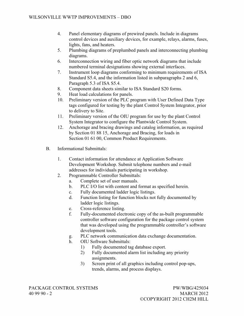
WILSONVILLE WWTP IMPROVEMENTS – DBO
PACKAGE CONTROL SYSTEMS PW/WBG/425034 40 99 90 - 2 MARCH 2012 ©COPYRIGHT 2012 CH2M HILL
4. Panel elementary diagrams of prewired panels. Include in diagrams control devices and auxiliary devices, for example, relays, alarms, fuses, lights, fans, and heaters.
5. Plumbing diagrams of preplumbed panels and interconnecting plumbing diagrams.
6. Interconnection wiring and fiber optic network diagrams that include numbered terminal designations showing external interfaces.
7. Instrument loop diagrams conforming to minimum requirements of ISA Standard S5.4, and the information listed in subparagraphs 2 and 6, Paragraph 5.3 of ISA S5.4.
8. Component data sheets similar to ISA Standard S20 forms. 9. Heat load calculations for panels. 10. Preliminary version of the PLC program with User Defined Data Type
tags configured for testing by the plant Control System Integrator, prior to delivery to Site.
11. Preliminary version of the OIU program for use by the plant Control System Integrator to configure the Plantwide Control System.
12. Anchorage and bracing drawings and catalog information, as required by Section 01 88 15, Anchorage and Bracing, for loads in Section 01 61 00, Common Product Requirements.
B. Informational Submittals:
1. Contact information for attendance at Application Software Development Workshop. Submit telephone numbers and e-mail addresses for individuals participating in workshop.
2. Programmable Controller Submittals: a. Complete set of user manuals. b. PLC I/O list with content and format as specified herein. c. Fully documented ladder logic listings. d. Function listing for function blocks not fully documented by
ladder logic listings. e. Cross-reference listing. f. Fully-documented electronic copy of the as-built programmable
controller software configuration for the package control system that was developed using the programmable controller’s software development tools.
g. PLC network communication data exchange documentation. h. OIU Software Submittals:
1) Fully documented tag database export. 2) Fully documented alarm list including any priority
assignments. 3) Screen print of all graphics including control pop-ups,
trends, alarms, and process displays.

WILSONVILLE WWTP IMPROVEMENTS – DBO
PW/WBG/425034 PACKAGE CONTROL SYSTEMS MARCH 2012 40 99 90 - 3 ©COPYRIGHT 2012 CH2M HILL
3. Manufacturer’s list of proposed spares, expendables, and test equipment.
4. Manufacturer’s Certificate of Proper Installation in accordance with Section 01 43 33, Manufacturers’ Field Services.
5. Anchorage and bracing calculations as required by Section 01 88 15, Anchorage and Bracing, for loads in Section 01 61 00, Common Product Requirements.
1.05 APPLICATION SOFTWARE DEVELOPMENT WORKSHOP
A. Attend an application software delivery workshop to ensure conformance with project-wide application software standards. The workshop will be held as a teleconference and/or live meeting. Workshop may be split into two separate sessions of up to 4 hours each.
B. Workshop Topics: Company will provide the following minimum required standards to be followed for all PLC and OIU application software:
1. Tag name and addressing conventions to follow. 2. User Defined Data Type structures to be used, including:
a. Motorized equipment. b. Actuated valves. c. Analog instruments.
3. PLC functionality, including conventions for status and alarms (on state and off state), LOCAL/REMOTE and AUTO/MANUAL control modes, PLC to PLC communication approach, communication monitoring, alarm acknowledgment and reset.
4. Graphic standards to be used: a. OIU standard objects, where applicable. b. Color conventions.
5. Control functions available from Plantwide Control System. 6. Software security approach. 7. Network address assignments. 8. Plantwide automatic restart sequence following power failure.
C. Required Attendance: Provide for workshop attendance by telephone and live meeting for the following individuals:
1. Manufacturer’s PLC software programmer responsible for project PLC application software, allow for up to 4 hours.
2. Manufacturer’s OIU software programmer responsible for project OIU application software, allow for up to 4 hours.
3. Manufacturer’s other project representatives, attendance as deemed necessary by manufacturer.

WILSONVILLE WWTP IMPROVEMENTS – DBO
PACKAGE CONTROL SYSTEMS PW/WBG/425034 40 99 90 - 4 MARCH 2012 ©COPYRIGHT 2012 CH2M HILL
1.06 DELIVERY, STORAGE, AND HANDLING
A. Prior to shipment, include corrosive-inhibitive vapor capsules in shipping containers and related equipment as recommended by capsule manufacturer.
PART 2 PRODUCTS
2.01 SIGNAL CHARACTERISTICS
A. Analog Signal, Current Type:
1. 4 to 20 mA dc signals conforming to ISA S50.1. 2. Unless otherwise indicated for specific PIC subsection components, use
the following ISA S50.1 options. a. Transmitter Type: Number 2, two-wire. b. Transmitter Load Resistance Capacity: Class L. c. Fully isolated transmitters and receivers.
B. Discrete signals, two-state logic signals using 120V ac sources as indicated.
C. Special Signals: Other types of signals used to transmit analog and digital information between field elements, transmitters, receivers, controllers, and digital devices.
2.02 CORROSION PROTECTION
A. Corrosion-Inhibiting Vapor Capsule Manufacturers:
1. Northern Instruments; Model Zerust VC. 2. Hoffmann Engineering; Model A-HCI.
2.03 CONTROL PANEL
A. Panel Construction and Interior Wiring: In accordance with the National Electrical Code (NEC), UL 508, state and local codes, and applicable sections of NEMA, ANSI, and ICECA.
B. Panels labeled prior to delivery to Site.
C. Conform to NEMA ratings as specified in individual equipment sections.
D. Minimum Metal Thickness: 14 gauge.
E. NEMA 250, Type 4X Panels: Type 304 stainless steel.

WILSONVILLE WWTP IMPROVEMENTS – DBO
PW/WBG/425034 PACKAGE CONTROL SYSTEMS MARCH 2012 40 99 90 - 5 ©COPYRIGHT 2012 CH2M HILL
F. Doors:
1. Three-point latching mechanisms in accordance with NEMA 250 Type 1 and 12 panels with doors higher than 18 inches.
2. For other doors, stainless steel quick release clamps.
G. Cutouts shall be cut, punched, or drilled and finished smoothly with rounded edges.
H. Access: Front, suitable for installation with back and sides adjacent to or in contact with other surfaces, unless otherwise specified.
I. Temperature Control:
1. Enclosures Installed Indoors in Conditioned Spaces: Size panels to adequately dissipate heat generated by equipment mounted on or in the panel. If necessary, furnish thermostatically controlled cooling fans with replaceable air filters. Derive power for the fans from the internal 120V ac control system.
2. Enclosures Installed Outdoors or Indoors in Spaces that are Not Conditioned: a. For enclosures with programmable logic controllers,
microprocessors or adjustable frequency drives, when noted or if required to meet panel components temperature ratings: 1) Provide NEMA 4/4X side-mounted or top-mounted closed-
loop air conditioning unit. Size the unit to maintain temperatures inside the enclosure to no more than 45 degrees C with an ambient temperature of 50 degrees C in full sun and the equipment operating at full load.
2) Air Conditioner Power: 120 volts, provided by an external circuit, for loads not to exceed 15A. For loads greater than 15A at 120V, notify CH2M HILL and request direction.
b. For Other Enclosures: Furnish thermostatically controlled fans with replaceable air filters to dissipate heat generated in the panel and heaters to maintain temperature above 40 degrees F. Provide thermostats to automatically control heating and cooling requirements to maintain the temperature inside the enclosure within the ratings of the components inside the enclosure.
J. Push-to-Test Circuitry: For each push-to-test indicating light, provide a fused push-to-test circuit.
K. Lighting: Minimum of one hand switch controlled internal 100-watt light for panels 12 cubic feet and larger.

WILSONVILLE WWTP IMPROVEMENTS – DBO
PACKAGE CONTROL SYSTEMS PW/WBG/425034 40 99 90 - 6 MARCH 2012 ©COPYRIGHT 2012 CH2M HILL
L. Minimum of one 120-volt GFCI duplex receptacle for panels 12 cubic feet and larger.
M. Finish:
1. Metallic External Surfaces (Excluding Aluminum and Stainless Steel): Manufacturer’s standard gray unless otherwise specified.
2. Internal Surfaces: White enamel.
N. Panel Manufacturers:
1. Hoffman. 2. H.F. Cox.
O. Breather and Drains: Furnish with NEMA 250, Type 4 and 4X panels.
1. Manufacturer and Products: Cooper Crouse-Hinds; ECD Type 4X Drain and Breather; Drain Model ECD1-N4D, Breather Model ECD1-N4B.
2.04 CONTROL PANEL ELECTRICAL
A. UL Listing Mark for Enclosures: Mark stating “Listed Enclosed Industrial Control Panel” per UL 508A.
B. I&C and electrical components, terminals, wires, and enclosures UL recognized or UL listed.
C. Control Panels without Motor Starters:
1. Furnish main circuit breaker and a circuit breaker on each individual branch circuit distributed from power panel.
2. Locate to provide clear view of and access to breakers when door is open. Group on single subpanel. Provide typed directory.
3. Circuit Breakers: a. Coordinate for fault in branch circuit trips, branch breaker, and
not main breaker. b. Branch Circuit Breakers: 15 amps at 250V ac. c. Breaker Manufacturers and Products:
1) Heineman Electric Co.; Series AM. 2) Airpax/North American Philips Controls Corp.; Series 205.
D. Control Panels with Three-Phase Power Supplies and Motor Starters:
1. Mount main circuit breaker on panel door. Include provisions for padlocking the main circuit breaker in the “OPEN” position. Interlock
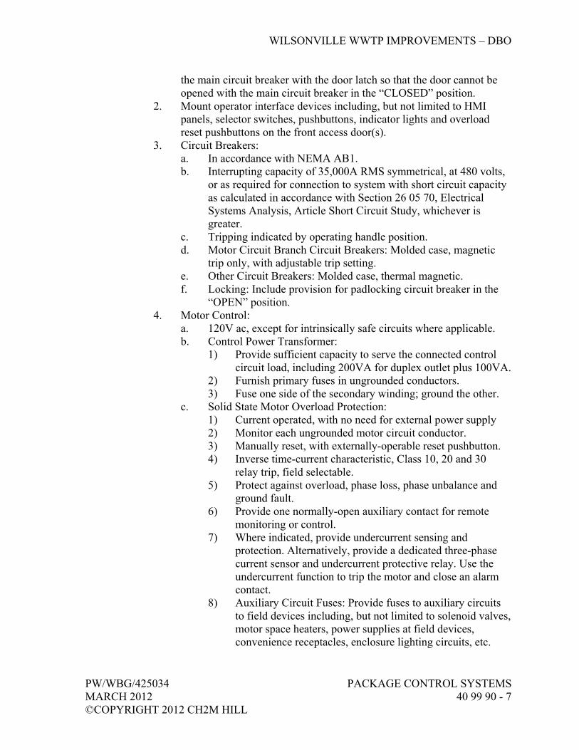
WILSONVILLE WWTP IMPROVEMENTS – DBO
PW/WBG/425034 PACKAGE CONTROL SYSTEMS MARCH 2012 40 99 90 - 7 ©COPYRIGHT 2012 CH2M HILL
the main circuit breaker with the door latch so that the door cannot be opened with the main circuit breaker in the “CLOSED” position.
2. Mount operator interface devices including, but not limited to HMI panels, selector switches, pushbuttons, indicator lights and overload reset pushbuttons on the front access door(s).
3. Circuit Breakers: a. In accordance with NEMA AB1. b. Interrupting capacity of 35,000A RMS symmetrical, at 480 volts,
or as required for connection to system with short circuit capacity as calculated in accordance with Section 26 05 70, Electrical Systems Analysis, Article Short Circuit Study, whichever is greater.
c. Tripping indicated by operating handle position. d. Motor Circuit Branch Circuit Breakers: Molded case, magnetic
trip only, with adjustable trip setting. e. Other Circuit Breakers: Molded case, thermal magnetic. f. Locking: Include provision for padlocking circuit breaker in the
“OPEN” position. 4. Motor Control:
a. 120V ac, except for intrinsically safe circuits where applicable. b. Control Power Transformer:
1) Provide sufficient capacity to serve the connected control circuit load, including 200VA for duplex outlet plus 100VA.
2) Furnish primary fuses in ungrounded conductors. 3) Fuse one side of the secondary winding; ground the other.
c. Solid State Motor Overload Protection: 1) Current operated, with no need for external power supply 2) Monitor each ungrounded motor circuit conductor. 3) Manually reset, with externally-operable reset pushbutton. 4) Inverse time-current characteristic, Class 10, 20 and 30
relay trip, field selectable. 5) Protect against overload, phase loss, phase unbalance and
ground fault. 6) Provide one normally-open auxiliary contact for remote
monitoring or control. 7) Where indicated, provide undercurrent sensing and
protection. Alternatively, provide a dedicated three-phase current sensor and undercurrent protective relay. Use the undercurrent function to trip the motor and close an alarm contact.
8) Auxiliary Circuit Fuses: Provide fuses to auxiliary circuits to field devices including, but not limited to solenoid valves, motor space heaters, power supplies at field devices, convenience receptacles, enclosure lighting circuits, etc.
WILSONVILLE WWTP IMPROVEMENTS – DBO
PACKAGE CONTROL SYSTEMS PW/WBG/425034 40 99 90 - 8 MARCH 2012 ©COPYRIGHT 2012 CH2M HILL
d. Power Distribution Blocks: Provide to make parallel connections to outgoing branch circuits.
e. Terminations for Power Conductors: Suitable for use with stranded copper conductors, rated 75 degrees C, at full NFPA 70. 75 degrees C ampacity.
E. Wiring:
1. ac Circuits: a. Type: 600-volt, Type MTW stranded copper. b. Size: For current to be carried, but not less than 14 AWG.
2. Analog Signal Circuits: a. Type: 600-volt, Type 2 stranded copper, twisted shielded pairs. b. Size: 18 AWG, minimum.
3. Other dc Circuits. a. Type: 600-volt, Type MTW stranded copper. b. Size: 18 AWG, minimum.
4. Separate analog and other dc circuits at least 6 inches from any ac power and control wiring.
5. Enclose wiring in sheet metal raceways or plastic wiring ducts. 6. Wire Identification: Numbered and tagged at each termination.
a. Wire Tags: Machine printed, heat shrink. b. Manufacturers:
1) Brady PermaSleeve. 2) Tyco Electronics.
F. Wiring Interface:
1. For analog and discrete signal, terminate at numbered terminal blocks. 2. For special signals, terminate power (240 volts or greater) at
manufacturer’s standard connectors. 3. For panel, terminate at equipment on/with which it is mounted.
G. Terminal Blocks:
1. Quantity: a. For external connections. b. Wire spare or unused panel mounted elements to their panels’
terminal blocks. c. Spare Terminals: 20 percent of connected terminals, but not less
than 10. 2. General: Group to keep 120V ac circuits separate from 24V dc circuits.
a. Connection Type: Screw connection clamp.

WILSONVILLE WWTP IMPROVEMENTS – DBO
PW/WBG/425034 PACKAGE CONTROL SYSTEMS MARCH 2012 40 99 90 - 9 ©COPYRIGHT 2012 CH2M HILL
b. Compression Clamp: 1) Hardened steel clamp with transversal grooves penetrating
wire strands providing a vibration-proof connection. 2) Guides strands of wire into terminal.
c. Screws: Hardened steel, captive, and self-locking. d. Current Bar: Copper or treated brass. e. Insulation:
1) Thermoplastic rated for minus 55 to plus 110 degrees C. 2) Two funnel shaped inputs to facilitate wire entry.
f. Mounting: 1) Rail. 2) Terminal block can be extracted from an assembly without
displacing adjacent blocks. 3) End Stops: One at each end of rail, minimum.
g. Wire Preparation: Stripping only. h. Jumpers: Allow jumper installation without loss of space on
terminal or rail. i. Marking System:
1) Terminal number shown on both sides of terminal block. 2) Allow use of preprinted and field marked tags. 3) Terminal strip numbers shown on end stops. 4) Mark terminal block and terminal strip numbers as shown.
3. Terminal Block, 120-Volt Power: a. Rated Voltage: 600V ac. b. Rated Current: 30-amp, minimum. c. Wire Size: 22 through 10 AWG. d. Rated Wire Size: 10 AWG. e. Color: Gray body. f. Spacing: 1/4-inch, maximum. g. Manufacturers:
1) Weidmuller. 2) Entrelec; Type M4/6. 3) Or equal.
4. Terminal Block, Ground: a. Wire Size: 22 through 12 AWG. b. Rated Wire Size: 12 AWG. c. Color: Green and yellow body. d. Spacing: 1/4-inch, maximum. e. Grounding: Ground terminal blocks electrically grounded to the
mounting rail. f. Manufacturers:
1) Weidmuller. 2) Entrelec; Type M4/6.P. 3) Or equal.

WILSONVILLE WWTP IMPROVEMENTS – DBO
PACKAGE CONTROL SYSTEMS PW/WBG/425034 40 99 90 - 10 MARCH 2012 ©COPYRIGHT 2012 CH2M HILL
5. Terminal Block, Blade Disconnect Switch: a. Use: Provide one for each discrete input and output field interface
wire. b. Rated Voltage: 600V ac. c. Rated Current: 10-amp. d. Wire Size: 22 through 12 AWG. e. Rated Wire Size: 12 AWG. f. Color: Gray body, orange switch. g. Spacing: 1/4- inch, maximum. h. Manufacturers and Products:
1) Weidmuller. 2) Entrelec; Type M4/6.SN. 3) Or equal.
6. Terminal Block, Fused, 24V dc: a. Rated Voltage: 600V dc. b. Rated Current: 6.3-amp. c. Wire Size: 22 through 12 AWG. d. Rated Wire Size: 12 AWG. e. Color: Gray body. f. Fuse: 5 by 20 GMA fuses. g. Fuse Marking: Fuse amperage rating shown on top of terminal
block. h. Indication: LED diode 24V dc. i. Leakage Current: 5.2 mA, maximum. j. Spacing: 0.32-inch, maximum. k. Manufacturers and Products:
1) Square D. 2) Weidmuller. 3) Entrelec; Type M4/6.SFD. 4) Or equal.
7. Terminal Block, Fused, 120V ac: a. Rated Voltage: 600V ac. b. Rated Current: 6.3-amp. c. Wire Size: 22 through 12 AWG. d. Rated Wire Size: 12 AWG. e. Color: Gray body. f. Fuse: 5 by 20 GMA fuses. g. Fuse Marking: Fuse amperage rating shown on top of terminal
block. h. Indication: Neon lamp 110V ac. i. Leakage Current: 1.8 mA, maximum. j. Spacing: 0.32-inch, maximum. k. Manufacturers and Products:
1) Square D. 2) Weidmuller.
WILSONVILLE WWTP IMPROVEMENTS – DBO
PW/WBG/425034 PACKAGE CONTROL SYSTEMS MARCH 2012 40 99 90 - 11 ©COPYRIGHT 2012 CH2M HILL
3) Entrelec; Type M4/6.SFL. 4) Or equal.
H. Grounding: Internal copper grounding bus for ground connections on panels, consoles, racks, and cabinets.
I. Relays:
1. General: a. Relay Mounting: Plug-in type socket. b. Relay Enclosure: Provide dust cover. c. Socket Type: Screw terminal interface with wiring. d. Socket Mounting: Rail. e. Furnish holddown clips.
2. Control Circuit Switching Relay, Nonlatching: a. Type: Compact general purpose plug-in. b. Contact Arrangement: 3 Form C contacts. c. Contact Rating: 10A at 28V dc or 240V ac. d. Contact Material: Silver cadmium oxide alloy. e. Coil Voltage: As noted or shown. f. Coil Power: 1.8 watts (dc), 2.7VA (ac). g. Expected Mechanical Life: 10,000,000 operations. h. Expected Electrical Life at Rated Load: 100,000 operations. i. Indication Type: Neon or LED indicator lamp. j. Push-to-test button. k. Manufacturer and Product: Potter and Brumfield; Series KUP.
3. Control Circuit Switching Relay, Latching: a. Type: Dual coil mechanical latching relay. b. Contact Arrangement: 2 Form C contacts. c. Contact Rating: 10A at 28V dc or 120V ac. d. Contact Material: Silver cadmium oxide alloy. e. Coil Voltage: As noted or shown. f. Coil Power: 2.7 watts (dc), 5.3VA (ac). g. Expected Mechanical Life: 500,000 operations. h. Expected Electrical Life at Rated Load: 50,000 operations. i. Manufacturer and Product: Potter and Brumfield; Series KB/KBP.
4. Control Circuit Switching Relay, Time Delay: a. Type: Adjustable time delay relay. b. Contact Arrangement: 2 Form C contacts. c. Contact Rating: 10A at 240V ac. d. Contact Material: Silver cadmium oxide alloy. e. Coil Voltage: As specified or shown. f. Operating Temperature: Minus 10 to 55 degrees C. g. Repeatability: Plus or minus 2 percent.
WILSONVILLE WWTP IMPROVEMENTS – DBO
PACKAGE CONTROL SYSTEMS PW/WBG/425034 40 99 90 - 12 MARCH 2012 ©COPYRIGHT 2012 CH2M HILL
h. Delay Time Range: Select range such that time delay setpoint fall between 20 to 80 percent or range.
i. Time Delay Setpoint: As specified or shown. j. Mode of Operation: As specified or shown. k. Adjustment Type: Integral potentiometer with knob external to
dust cover. l. Manufacturer and Products: Potter and Brumfield.
1) Series CB for 0.1-second to 100-minute delay time ranges. 2) Series CK for 0.1- to 120-second delay time ranges.
J. Intrinsic Safety Barriers:
1. Intrinsically Safe Relays: Monitor discrete signals that originate in hazardous area and are used in a safe area. a. Manufacturer: Phoenix Contact.
2. Intrinsically Safe Barriers: Interface analog signals as they pass from hazardous area to safe area. a. Manufacturer: Phoenix Contact.
K. Programmable Controllers:
1. Solid state units capable of performing same function as conventional relays, timers, counters, drum sequencers, arithmetic, and other special functions necessary to perform required control functions.
2. Minimum of 12 discrete inputs and 8 discrete outputs, optical isolations rated at 2,500-volt rms. Discrete inputs shall be 120V ac. Discrete outputs shall be rated for 2 amps at 120V ac. Each input and output shall have an LED ON/OFF status indicator.
3. Analog inputs and outputs shall be isolated 4 to 20 mA dc signals. 4. Minimum of 25 percent excess capacity for inputs, outputs, internal
coils, registers, and other necessary functions. 5. Provide Ethernet network communications module for communications
with other PLCs and Operator Interface computers. 6. Capable of operating in a hostile industrial environment (for example,
heat, electrical transients, RFI, and vibration) without fans, air conditioning, or electrical filtering. Units operate from 0 to 60 degrees C and up to 95 percent humidity, noncondensing.
7. Program using conventional relay ladder diagram notation. PLC programming shall be in accordance with IEC standard 61131.
8. Manufacturer and Product: a. Allen-Bradley; ControlLogix, or CompactLogix. No exceptions. b. Allen-Bradley ControlLogix Processors and Modules:
1) Control Processor: Allen-Bradley Model 1756-L62. 2) Power Supply Module: Allen-Bradley Model 1756-PA75R.

WILSONVILLE WWTP IMPROVEMENTS – DBO
PW/WBG/425034 PACKAGE CONTROL SYSTEMS MARCH 2012 40 99 90 - 13 ©COPYRIGHT 2012 CH2M HILL
3) Ethernet Communication Module: Allen-Bradley Model 1756-EN2T.
4) ControlNet Module: Allen-Bradley Model 1756-CN2. 5) Digital Input Module: Allen-Bradley Model 1756-IA16I
with Model 1756-TBCH I/O Module Terminal Interface. 6) Digital Output Module: Allen-Bradley Model 1756-OA16I
with Model 1756-TBCH I/O Module Terminal Interface. 7) Analog Input Module: Allen-Bradley Model 1756-IF8H
(HART interface) with Model 1756-TBCH I/O Module Terminal Interface.
8) Analog Output Module: Allen-Bradley Model 1756-OF8 with Model 1756-TBCH I/O Module Terminal Interface.
L. Operator Interface Unit (OIU):
1. General: Operator interface shall be Allen-Bradley, as specified below, unless otherwise noted in the equipment specifications.
2. Operator Interface Unit: Units shall be Allen-Bradley: a. PanelViewPlus CE 1000 Color Keypad/ Touchscreen for systems
with one PLC per equipment train. b. PanelViewPlus CE 1500 Color Keypad/ Touchscreen for systems
with one PLC for multiple equipment trains.
M. Y40 Uninterruptible Power Supply (UPS) System:
1. Provide when noted: UPS for PLCs, Operator Interface Units, and Network Components.
2. Line-Interactive Type UPS: The battery-to-ac power converter (inverter) shall always be connected to the UPS output. Battery charging shall be provided by operating the inverter in reverse when the input ac power is normal. When the ac input power fails, the transfer switch shall open to disconnect input power, and power flow shall be from battery through the inverter to UPS output. The inverter shall be designed such that failure of the inverter shall not prevent ac input power to flow to the UPS output.
3. Provide load protection from both common and normal mode noise, voltage sags, surges, spikes, brownouts, and power failures. Input power source shall be 120V ac, 60-Hz.
4. Surge Suppression: ANSI/IEEE C62-41 Category A, UL 1449 listed. 5. Provide output of 120V, 60-Hz, sine wave with voltage regulation of
plus or minus 3 percent, operating over a temperature range of 32 to 104 degrees F at a relative humidity of 95 percent. Common mode and normal mode filtering shall be 38 dB minimum.
6. Provide UPS with sealed maintenance free battery and include a continuous battery charger that tapers to a float charge to maintain the

WILSONVILLE WWTP IMPROVEMENTS – DBO
PACKAGE CONTROL SYSTEMS PW/WBG/425034 40 99 90 - 14 MARCH 2012 ©COPYRIGHT 2012 CH2M HILL
battery. The unit shall be rated adequately to serve all components and functions indicated, plus 25 percent reserve capacity. Battery shall be sized sufficiently to provide rated power for a minimum of 30 minutes at full connected load during a power failure.
7. Provide dry contact closures for external alarm connection on failure of the UPS and on a low battery condition.
8. Perform a full load test and include the test results with each unit. 9. Manufacturers and Products:
a. American Power Conversion; Model Smart-UPS Series. b. Best Power; Model Fortress Series. c. Or equal.
N. Front-of-Panel Devices in Conjunction with NEMA 250, Type 1 and 12 Panels:
1. Potentiometer Units: a. Three-terminal, 30-mm oiltight construction, resolution of
1 percent and linearity of plus or minus 5 percent. b. Single-hole, panel mounting accommodating panel thicknesses
between 1/8 and 1/4 inch. c. Include legend plates with service markings. d. Manufacturers and Products:
1) Allen-Bradley; Model 800T. 2) Eaton/Cutler-Hammer; Model 10250T.
2. Indicating Lights: a. Heavy-duty, push-to-test type, oiltight, industrial type LED,
30 mm for 120V ac applications. b. Screwed on prismatic glass lenses in colors noted and factory
engraved legend plates for service legend. c. Manufacturers and Products:
1) Eaton/Cutler-Hammer; Type 10250T. 2) General Electric; CR2940U.
3. Pushbutton, Momentary: a. Heavy-duty 30 mm, oiltight, industrial type with full guard and
momentary contacts rated for 10 amperes continuous at 120V ac. b. STOP Pushbuttons: Provide with provision for padlocking in the
depressed position. c. Standard size legend plates with black field and white markings
for service legend. d. Manufacturers and Products:
1) Square D; Class 9001, Type K. 2) Eaton/Cutler-Hammer; Type T. 3) General Electric; Type CR-2940.
WILSONVILLE WWTP IMPROVEMENTS – DBO
PW/WBG/425034 PACKAGE CONTROL SYSTEMS MARCH 2012 40 99 90 - 15 ©COPYRIGHT 2012 CH2M HILL
4. Selector Switch: a. Heavy-duty 30 mm, oiltight, industrial type with contacts rated for
120V ac service at 10 amperes continuous. b. Standard size, black field, legend plates with white markings, for
service legend. c. Operators: Black knob type. d. Single-hole mounting, accommodating panel thicknesses from
1/16 inch to 1/4 inch. e. Manufacturers and Products for Units with up to Four Selection
Positions: 1) Eaton/Cutler-Hammer; Type T. 2) Square D; Type K.
f. Manufacturers and Products for Units with up to 12 Selection Positions: 1) Rundel-Idec; Standard Cam Switch. 2) Electroswitch; 31.
O. Front-of-Panel Devices Used in Conjunction with NEMA 250, Type 4X Panels:
1. Potentiometer, Watertight: a. Three-terminal, 30-mm heavy-duty NEMA 250, Type 4X
watertight construction, resolution of 1 percent and linearity of plus or minus 5 percent.
b. Single-hole, panel mounting accommodating panel thicknesses between 1/8 and 1/4 inch.
c. Include engraved legend plates with service markings. d. Manufacturer and Product: Allen-Bradley; Bulletin 800H.
2. Indicating Lights, Watertight: a. Heavy-duty, push-to-test type, NEMA 250, Type 4X watertight,
industrial type LED, 30 mm for 120V ac applications and corrosion-resistant service.
b. Screwed on prismatic glass lenses and factory engraved legend plates for service legend.
c. Manufacturers and Products: 1) Square D; Type SK. 2) Allen-Bradley; Type 800H.
3. Pushbutton, Momentary, Watertight: a. Heavy-duty 30 mm, NEMA 250, Type 4X watertight, industrial
type with momentary contacts rated for 120V ac service at 10 amperes continuous and corrosion-resistant service.
b. STOP Pushbuttons: Provide with provision for padlocking in the depressed position.
c. Standard size, black field, legend plates with white markings for service legend.

WILSONVILLE WWTP IMPROVEMENTS – DBO
PACKAGE CONTROL SYSTEMS PW/WBG/425034 40 99 90 - 16 MARCH 2012 ©COPYRIGHT 2012 CH2M HILL
d. Manufacturers and Products: 1) Square D; Type SK. 2) Allen-Bradley; Type 800H.
4. Selector Switch, Watertight: a. Heavy-duty 30 mm, NEMA 250, Type 4X watertight, industrial
type with contacts rated for 120V ac service at 10 amperes continuous and corrosion-resistant service.
b. Standard size, black field, legend plates with white markings, for service legend.
c. Operators: Black knob type. d. Single-hole mounting, accommodating panel thicknesses from
1/16 to 1/4 inch. e. Manufacturers and Products:
1) Square D; Class 9001, Type SK. 2) Allen-Bradley; Type 800H.
P. Network Components:
1. Fiber Optic Patch Panel: a. Function: Provides a secure place to terminate fiber optic cables. b. Features:
1) Cable management hardware and labels. 2) Extended front cover for patch cord protection. 3) Connectors: Minimum 6 SC connectors each for entry and
exit, unless otherwise specified. 4) Construction: 16 ga cold rolled steel. 5) Mountings: Panel mount.
c. Manufacturer and Product: 1) Hubbell; FTU Series with FSP Adapter Panels, FC Duplex
Zirconia Ceramic Connectors. 2) No equals accepted.
2. Ethernet Switch: a. 8-Port Switch:
1) Eight Ethernet 10/100 ports. 2) Operating Temperature: Minus 40 degrees C to
85 degrees C. 3) Industrial DIN-Rail enclosure. 4) Power Input: 10 to 30V dc. 5) Manufacturer and Product:
a) N-TRON; 708TX. b) No equal accepted.

WILSONVILLE WWTP IMPROVEMENTS – DBO
PW/WBG/425034 PACKAGE CONTROL SYSTEMS MARCH 2012 40 99 90 - 17 ©COPYRIGHT 2012 CH2M HILL
2.05 SOFTWARE REQUIREMENTS
A. Applications Software: Applications software program code and software configuration information for PLCs, OIUs, and network components shall be non-proprietary and fully documented, to allow the plant Control System Integrator to interface with and to operate, configure, and maintain the software. Key subroutines of the PLC program may be password-protected to maintain intellectual property, if necessary. All portions of the software which involve interface with the plant SCADA system must be accessible for review and troubleshooting.
B. All application software shall follow project standards as set forth in the Application Software Development Workshop.
C. Coordination and Testing:
1. 45 days prior to delivery to Site, submit a preliminary version of the PLC program with User Defined Data Type tags configured for testing by the System Integrator.
2. 45 days prior to delivery to Site, submit a preliminary version of the OIU program for use by the System Integrator to develop the Plantwide Control System.
3. Provide dedicated time for coordinating final data point definitions with the System Integrator.
4. Test complete system, including PLC and OIU software, at manufacturer’s facility prior to shipment to site. Notify Company at least 4 weeks in advance of this Factory Test, and make provisions for test to be witnessed by System Integrator or other Company representative. Test shall include the interface with the Plantwide Control System.
2.06 PLC NETWORK INTERFACE
A. General:
1. PLCs shall communicate with the plant PLCs and HMI computers. 2. PLC communications shall be via the plant Ethernet control system
network.
B. Data Exchange:
1. Use RA ControlLogix User Defined Data Types to communicate the specified data points with member names to and from the plant PLC. Coordinate with Owner’s System Integrator.
2. Network message traffic controlled by the Plant SCADA. All read and write message instructions will be executed by the Plant SCADA.

WILSONVILLE WWTP IMPROVEMENTS – DBO
PACKAGE CONTROL SYSTEMS PW/WBG/425034 40 99 90 - 18 MARCH 2012 ©COPYRIGHT 2012 CH2M HILL
3. Provide network communication failure monitoring and detection with a “heartbeat” signal.
4. For data which is not configured in one of the project-specific User Defined Data Types, organize data values to be exchanged into contiguous register blocks. One block for each of the following types: a. Analog data to be sent. b. Analog data to be received. c. Discrete data to be sent. d. Discrete data to be received.
5. Format for Analog Values: Engineering units using double precision floating point format.
6. Format for Discrete Values: 16-bit binary words (representing 16 unique status or alarm conditions).
2.07 PLC I/O LIST AND TAG NAMES
A. Provide an input/output (I/O) list for each PLC with the following columns:
1. Description: A description of each I/O point. 2. I/O Type: Choice of Analog Input (AI), Analog Output (AO), Digital
Input (DI), Digital Output (DO). 3. Low (0 Percent): The 0 percent engineering unit value for an analog
signal; ”zero state” descriptor for a discrete signal denoting the state when the discrete input polarity is 0 (example for a DI would be CLOSED for a valve status input).
4. High (100 Percent): The 100 percent or full span engineering unit value for an analog signal; “one state” descriptor for a discrete signal denoting the state when the discrete input polarity is 1 (example for a DI would be OPEN for a valve status input).
5. Eng Units: Example gpm, FT, MGD, SCFM, psi, Deg F, A, V, W, VA. 6. PLC Number: PLC reference number (as assigned for the project). 7. Building or Area No. Building or area reference number (two
characters). 8. Loop Sequence Number: A three-digit number defining the loop
number. 9. Equip Number: A two-digit number defining the device number. 10. Isa Id: The ISA identifier. 11. Tag Suffix: A tag suffix denoting the IO point function (Example
FLOW for an analog flow input). 12. Tag Name: Tag name for each I/O point. 13. I/O Name: The point ADDRESS in the PLC Database. 14. Chassis Slot: Slot the IO Point is terminated. 15. Point Number: I/O point number. 16. Comments: Reserved for special instructions.
WILSONVILLE WWTP IMPROVEMENTS – DBO
PW/WBG/425034 PACKAGE CONTROL SYSTEMS MARCH 2012 40 99 90 - 19 ©COPYRIGHT 2012 CH2M HILL
B. I/O Tag Name Format:
1. <ISA Id><Bldg/Area No.> _<Loop Seq No.><Equip No.> <Tag Suffix> Example: HS63_ 12305OPEN
C. Network I/O Points:
1. Assign I/O tag names and provide a listing of I/O points that are communicated via Ethernet networks.
2. Identify network I/O point types as follows: Analog Input (NAI), Analog Output (NAO), Digital Input (NDI), Digital Output (NDO).
2.08 INSTRUMENT TAG NUMBERS
A. Use project standard format as defined as follows:
Format: FIT65_32105
Notation Explanation
FIT ISA designator for Flow Indicating Transmitter
65 Building/Area number
321 Loop tag number differentiator (3 digits)
05 Sequence number (2 digits)
2.09 NAMEPLATES, NAMETAGS, AND SERVICE LEGENDS
A. Panel Nameplates: For identification of panels and components mounted thereon.
1. Nameplate Size and Material: 3/32-inch thick laminated phenolic type with black matte finish surface and white letter engraving.
2. Panel Identification Nameplates: 1/2-inch high letter engravings. 3. Panel Mounted Component (e.g., Control Devices, Indicating Lights,
Selector Switches, etc.). a. Identification Nameplates: 1/4-inch high letter engravings.
4. Attached to the panel face with two stainless steel self-tapping screws. 5. Nameplate Engravings: Include the instrument or equipment tag number
and descriptive title as shown and specified.
B. Internally Mounted Instruments Tags:
1. Tag Numbers: As listed in the Contract Documents.

WILSONVILLE WWTP IMPROVEMENTS – DBO
PACKAGE CONTROL SYSTEMS PW/WBG/425034 40 99 90 - 20 MARCH 2012 ©COPYRIGHT 2012 CH2M HILL
2. Identifying Tag Number: Permanently etched or embossed onto a stainless steel tag which shall be fastened to the device housing with stainless steel rivets or self tapping screws of appropriate size.
3. Where neither of the above fastenings can be accomplished, tags shall be permanently attached to the device by a circlet of 1/16-inch diameter stainless steel wire rope.
4. Identification Tag: Installed so that the numbers are easily visible to service personnel.
5. Front of Panel Mounted Instruments: Tag attached to rear of device.
C. Tagging of the following items shall be accomplished with the use of adhesive plastic Brady USA, Inc. labels, or equal.
1. Tag all electrical devices (e.g., relays, timers, power supplies) mounted within control panels and enclosures.
2. Tag all pneumatic lines. 3. Numerically tag all terminal blocks. 4. Numerically tag wiring at each end.
D. Standard Light Colors and Inscriptions: Unless otherwise specified in individual equipment specifications, use the following color code and inscriptions:
Tag Inscription(s) Color
ON ON Red
OFF OFF Green
OPEN OPEN Red
CLOSED CLOSED Green
LOW LOW Amber
FAIL FAIL Amber
HIGH HIGH Amber
AUTO AUTO White
MANUAL MANUAL Yellow
LOCAL LOCAL White
REMOTE REMOTE Yellow
FORWARD FORWARD Red
REVERSE REVERSE Blue

WILSONVILLE WWTP IMPROVEMENTS – DBO
PW/WBG/425034 PACKAGE CONTROL SYSTEMS MARCH 2012 40 99 90 - 21 ©COPYRIGHT 2012 CH2M HILL
1. Lettering: Black on white and amber lenses; white on red and green lenses.
2. Standard Pushbutton Colors and Inscriptions: a. Use following unless otherwise noted in Instrument List:
Tag Function Inscription(s) Color
OO ON OFF
Black Black
OC OPEN CLOSE
Black Black
OCA OPEN CLOSE AUTO
Black Black Black
OOA ON OFF
AUTO
Black Black Black
MA MANUAL AUTO
Black Black
SS START STOP
Black Red
LR LOCAL REMOTE
Black Black
RESET RESET Black
EMERGENCY STOP
EMERGENCY STOP
Red
b. Lettering Color: 1) Black on white and yellow buttons. 2) White on black, red, and green buttons.
2.10 ELECTRICAL SURGE AND TRANSIENT PROTECTION
A. General: Equip control panels with surge-arresting devices to protect equipment from damage due to electrical transients induced in interconnecting lines from lightning discharges and nearby electrical devices.
B. Suppressor Locations:
1. At point of connection between each equipment item and its power supply conductors (direct wired equipment).

WILSONVILLE WWTP IMPROVEMENTS – DBO
PACKAGE CONTROL SYSTEMS PW/WBG/425034 40 99 90 - 22 MARCH 2012 ©COPYRIGHT 2012 CH2M HILL
2. In other locations where equipment sensitivity to surges and transients requires additional protection beyond that inherent to design of equipment.
C. Power Supply Suppressor Assemblies:
1. Suitable for connection to 120-volt, single-phase power supplies EDCO “HSP SERIES.”
2. Suitable for connection to 480-volt, three-phase power supplies; Square D J9200-9A.
D. Grounding: Coordinate surge suppressor grounding in field panels and field instrumentation as specified in Section 26 05 26, Grounding and Bonding for Electrical Systems, and suppressor manufacturer’s requirements. Furnish control panels with an integral copper grounding bus for connection of suppressors and other required instrumentation.
PART 3 EXECUTION
3.01 ELECTRICAL POWER AND SIGNAL WIRING
A. Restrain control and signal wiring in control panels by plastic ties or ducts. Secure hinge wiring at each end so bending or twisting will occur around the longitudinal axis of wire. Protect bend area with a sleeve.
B. Arrange wiring neatly, cut to proper length, and remove surplus wire. Install abrasion protection for wire bundles passing through holes or across edges of sheet metal.
C. Use manufacturer’s recommended tool with sized anvil for crimp terminations. No more than one wire may be terminated in a single crimp lug. No more than two lugs may be installed on a single screw terminal.
D. Do not splice or tap wiring except at device terminals or terminal blocks.
3.02 STARTUP AND TESTING
A. Provide Functional Tests and Performance Tests of the complete control system including software functions to support startup of plant.
B. Prior to facility startup, inspect, test, and document that the control system is ready for operation.
C. Verify instruments, panels, and components for proper installation, calibration, and adjustment, on a loop-by-loop and component-by-component
WILSONVILLE WWTP IMPROVEMENTS – DBO
PW/WBG/425034 PACKAGE CONTROL SYSTEMS MARCH 2012 40 99 90 - 23 ©COPYRIGHT 2012 CH2M HILL
basis. Document results on loop test status reports, instrument calibration sheets, test forms, and check lists.
D. Perform functional tests including software functions and data communications for all control, monitoring and alarm loops and document test results on test procedure forms.
E. Provide on-site testing and startup time devoted to data exchange testing, message validation and network timing validation with plant SCADA.
3.03 PROTECTION
A. Protect enclosures and other equipment containing electrical, instrumentation and control devices, including spare parts, from corrosion through the use of corrosion-inhibiting vapor capsules.
B. During Work, periodically replace capsules in accordance with capsule manufacturer’s recommendations. Replace capsules at Substantial Completion.
END OF SECTION
