wilson audio watt (wilson audio tiny tot) precision loudspeaker system was de-signed and developed...
TRANSCRIPT
Wilson Audio is a registered trademark of Wilson Audio Specialties Inc.WATT/Puppy is a registered trademark of Wilson Audio Specialties Inc.
This manual was produced by the Wilson Audio Engineering Department in cooperation with Sales and Marketing. The information contained here in is subject to change without notice. Current Revi-sion 1.0, if you are in need of a more recent manual please contact your dealer.
The information in this manual is the sole property of Wilson Audio Specialties Inc. any reproduction in whole or in part without the express written permission of Wilson Audio Specialties Inc. is prohibited. No material contained here in may be transmitted in any form or by any means, electronic or mechanical, for any purpose, without the express written permission of Wilson Audio Specialties Inc.
WATT VieWs And MAgneTic Fields . . . . . . . . . . . . . . . . . . . . . . . . . . . . . . . . . . . . . . . . iiiWATT inTroducTion . . . . . . . . . . . . . . . . . . . . . . . . . . . . . . . . . . . . . . . . . . . . . . . . . . . . .1 Applications . . . . . . . . . . . . . . . . . . . . . . . . . . . . . . . . . . . . . . . . . . . . . . . . . . . . 1-1 Design Considerations . . . . . . . . . . . . . . . . . . . . . . . . . . . . . . . . . . . . . . . . . . . . 1-2 Enclosure Materials Technology . . . . . . . . . . . . . . . . . . . . . . . . . . . . . . . . . . . . 1-3 Care of the Finish of your WATTs . . . . . . . . . . . . . . . . . . . . . . . . . . . . . . . . . . . 1-5 Connection of your WATTs . . . . . . . . . . . . . . . . . . . . . . . . . . . . . . . . . . . . . . . . 1-6 Selection of Interchangeable Tuning Ports . . . . . . . . . . . . . . . . . . . . . . . . . . . . . 1-7 Mounting Heights . . . . . . . . . . . . . . . . . . . . . . . . . . . . . . . . . . . . . . . . . . . . . . . . 1-8
PuPPy- sTAndArd VieWs . . . . . . . . . . . . . . . . . . . . . . . . . . . . . . . . . . . . . . . . . . . . . . . . . 2-1PuPPy inTroducTion . . . . . . . . . . . . . . . . . . . . . . . . . . . . . . . . . . . . . . . . . . . . . . . . . . . . 2-2 Cabinet Design . . . . . . . . . . . . . . . . . . . . . . . . . . . . . . . . . . . . . . . . . . . . . . . . . . 2-2 Design Considerations . . . . . . . . . . . . . . . . . . . . . . . . . . . . . . . . . . . . . . . . . . . . 2-3 Care of the Finish of your Puppy . . . . . . . . . . . . . . . . . . . . . . . . . . . . . . . . . . . . 2-3 . . . . . . . . . . . . . . . . . . . . . . . . . . . . . . . . . . . . . . . . . . . . . . . . . . . . . . . . . . . . . . . . . .in your rooM . . . . . . . . . . . . . . . . . . . . . . . . . . . . . . . . . . . . . . . . . . . . . . . . . . . . . . . . . .3 RoomReflections . . . . . . . . . . . . . . . . . . . . . . . . . . . . . . . . . . . . . . . . . . . . . . . . 3-1 Resonances . . . . . . . . . . . . . . . . . . . . . . . . . . . . . . . . . . . . . . . . . . . . . . . . . . . . . 3-5 Room Shapes . . . . . . . . . . . . . . . . . . . . . . . . . . . . . . . . . . . . . . . . . . . . . . . . . . . 3-6 Effect of Room Placement . . . . . . . . . . . . . . . . . . . . . . . . . . . . . . . . . . . . . . . . . 3-8 Speaker Placement/Listening Position . . . . . . . . . . . . . . . . . . . . . . . . . . . . . . . 3-13 Choosing a Listening Position . . . . . . . . . . . . . . . . . . . . . . . . . . . . . . . . . . . . . 3-13 Speaker Orientation . . . . . . . . . . . . . . . . . . . . . . . . . . . . . . . . . . . . . . . . . . . . . 3-14 Summary . . . . . . . . . . . . . . . . . . . . . . . . . . . . . . . . . . . . . . . . . . . . . . . . . . . . . . 3-14
sysTeM seTuP . . . . . . . . . . . . . . . . . . . . . . . . . . . . . . . . . . . . . . . . . . . . . . . . . . . . . . . . . . .4 Preparation . . . . . . . . . . . . . . . . . . . . . . . . . . . . . . . . . . . . . . . . . . . . . . . . . . . . . 4-1 Setup . . . . . . . . . . . . . . . . . . . . . . . . . . . . . . . . . . . . . . . . . . . . . . . . . . . . . . . . . . 4-2 Puppy Tail Connection . . . . . . . . . . . . . . . . . . . . . . . . . . . . . . . . . . . . . . . . . . . . 4-5 Puppy Paws . . . . . . . . . . . . . . . . . . . . . . . . . . . . . . . . . . . . . . . . . . . . . . . . . . . . . 4-6AlignMenT TAbles . . . . . . . . . . . . . . . . . . . . . . . . . . . . . . . . . . . . . . . . . . . . . . . . . . . . . . .5
T a b l e o f C o n T e n T s


Figure 1-WATT design considerATions . . . . . . . . . . . . . . . . . . . . . . . . . . . . . . . . . . . . 1-2Figure 2-binding PosT connecTion . . . . . . . . . . . . . . . . . . . . . . . . . . . . . . . . . . . . . . . 1-6Figure 3-WATT on Floor . . . . . . . . . . . . . . . . . . . . . . . . . . . . . . . . . . . . . . . . . . . . . . . 1-9Figure 4-WATT on 18 inch sTAnd . . . . . . . . . . . . . . . . . . . . . . . . . . . . . . . . . . . . . . . . 1-10Figure 5-WATT on 24 inch sTAnd . . . . . . . . . . . . . . . . . . . . . . . . . . . . . . . . . . . . . . . . 1-11Figure 6-WATT on PuPPy . . . . . . . . . . . . . . . . . . . . . . . . . . . . . . . . . . . . . . . . . . . . . . 1-12Figure 7-coMMoM reFlecTion ProbleMs . . . . . . . . . . . . . . . . . . . . . . . . . . . . . . . . . . 3-1Figure 8-reFlecTiVe coMb FilTer eFFecT . . . . . . . . . . . . . . . . . . . . . . . . . . . . . . . . . 3-4Figure 9-coMMon rooM shAPes . . . . . . . . . . . . . . . . . . . . . . . . . . . . . . . . . . . . . . . . . 3-7Figure 10-WATT PosiTions . . . . . . . . . . . . . . . . . . . . . . . . . . . . . . . . . . . . . . . . . . . . . . 3-9Figure 11-WATTs Toed in . . . . . . . . . . . . . . . . . . . . . . . . . . . . . . . . . . . . . . . . . . . . . . 3-10Figure 12-ideAl WATT seTuP . . . . . . . . . . . . . . . . . . . . . . . . . . . . . . . . . . . . . . . . . . . 3-12Figure 13-WATT/PuPPy resPonse . . . . . . . . . . . . . . . . . . . . . . . . . . . . . . . . . . . . . . . . 3-15Figure 14-ToP oF PuPPy . . . . . . . . . . . . . . . . . . . . . . . . . . . . . . . . . . . . . . . . . . . . . . . . 4-1Figure 15-WATT sPike insTAllATion . . . . . . . . . . . . . . . . . . . . . . . . . . . . . . . . . . . . . . . 4-2Figure 16-PlAceMenT oF WATT on PuPPy . . . . . . . . . . . . . . . . . . . . . . . . . . . . . . . . . . 4-3Figure 17-WATT AlignMenT sPike PlAceMenT . . . . . . . . . . . . . . . . . . . . . . . . . . . . . . 4-4Figure 18-PuPPy PAW AsseMbly . . . . . . . . . . . . . . . . . . . . . . . . . . . . . . . . . . . . . . . . . . 4-7
T a b l e o f G r a p h i C s
ii
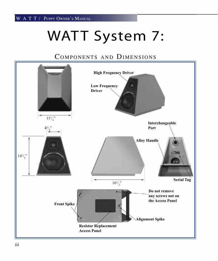
WAT T System 7:Co m p o n e n T s a n d di m e n s i o n s
W a T T / puppy oWner’s manual
iii
111/4”
43/4”
141/8”
161/2”
Low Frequency Driver
Interchangeable Port
Serial Tag
Alloy Handle
High Frequency Driver
Do not removeany screws not on the Access Panel
Alignment Spike
Resistor ReplacementAccess Panel
Front Spike

iv
ma G n e T i C fi e l d s - s i d e Vi e W
W a T T V i e W s
WAT T System 7:
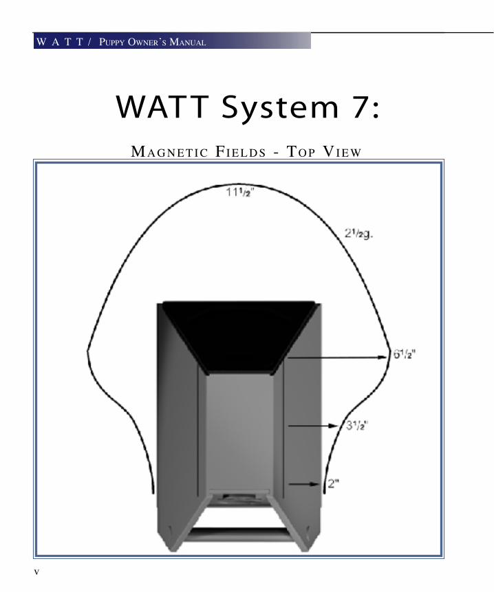
ma G n e T i C fi e l d s - To p Vi e W
v
W a T T / puppy oWner’s manual
WAT T System 7:


1W a T T i n T r o d u C T i o n


1-1
Although they are two separate products, the Wilson Au-dio WATT and Puppy are almost invariably used together.
Thus, it seems appropriate to combine information regard-ing their use into one convenient manual.
ApplicAtions
Your WATT (Wilson Audio Tiny Tot) precision loudspeaker system was de-signed and developed by David A. Wilson to serve as a highly accurate yet portable professional monitor for on-location recording work. Microphone pattern selection and placement as well as master tape evaluations may be quickly and correctly performed using the WATT. The extraordinary transparency, coherence, and dynamic linearity of the WATT also make it ideal for the sonic evaluation of audio hardware and software, includingassociatedelectronicaudioequipment,suchas,amplificationsystems,D/Aconverters, passive circuit components, signal cables, solders, and contact treatments. Its capabilities of high resolution, accurate tonal and harmonic integrity, and unsur-passed sound-stage recreation make it an ideal system for the most demanding music lovers. In the application as a center channel for video systems the WATT (usually with A.V. Puppy), provides unrivaled dialogue intelligibility and convincing dynamics. The WATT’s size and color options allow it to be integrated harmoniously into a wide vari-etyoffineinteriordecors. design considerATions
W a T T i n T r o d u C T i o n

The WATT is designed around a massive, yet compact, enclosure utilizing pro-prietary polymer materials technology. The enclosure material exhibits excellent inter-nal damping and a correct mechanical impedance match to the frames of the drivers. Additional mechanical tuning is provided by null point placement of lead alloy ingot blocks, bituminous surface treatment and rigid cross-bracing.The acoustical tuning of the low frequency system is modeled after the quasi-third order Butterworth response, (seefigure1below),whichprovideslinearityintheupper-bass(withouttheusualmid-bass hump) with superior transient performance. The low-frequency range of the system is normally extended with a Wilson Audio Puppy high speed woofer. The crossover network uses multiple slopes to achieve acoustical phase linearity. Minimum energy/time-storagebehaviorinthecrossoverisachievedbyusingonlythefinestaudio-grade
W A t t D e s i g n c o n s i D e r A t i o n s :T h i e l e & S m a l l A l i g n m e n t s
W a T T / puppy oWner’s manual
Figure 11-2

1-3
propylene capacitors, OFC air-core inductors, and time coherent wire. The components are matched to better than 0.1% tolerance. The drivers were selected because of their frequency response linearity, impulse stability, and most important, their intrinsic musi-cal quality.
enclosure MATeriAls Tech-
nology
The original WATT established the textbook standard for sonically inert
loudspeaker enclosures. It pioneered the use of exotic cabinet materials coupled with
a new benchmark for construction quality, achieving a speaker enclosure that remains
unsurpassed to this day. The System 7 employs the strategic use of a new cabinet mate-
rial that, in conjunction with existing “X” material, serves to reduce cabinet colorations
to levels below that of the already extraordinary System 6. Distortion, noise, and audible
enclosure resonance are all substantially reduced in the System 7. This results in much
greater clarity, resolution and tonal correctness as well as an enhanced sense of effort-
lessnessandease.Dynamicsaremoreclearlydefinedanddelineated.Musicflowsfrom
a blacker background. This material has been chosen because it provides a nearly ideal
blend of rigidity, mass, and internal vibration damping.
THE WATT ENCLOSURE MATERIAL SHOULD BE TREATED AS THOUGH IT WERE CERAMIC!
THE MATERIAL WILL NOT BEND, BUT INSTEAD WILL CRACK. FOR THIS REASON USERS OF THE WATT SHOULD NOT TO ATTEMPT DISASSEMBLY OF THE SYSTEM.
W a T T i n T r o d u C T i o n
THE WATT: A TEXTBOOK IDEAL
The following is an excerpt from Martin Colloms’ book High Performance Loudspeak-ers , (4th Edition, pp.297-299. Pentech Press, London, 1991):
“Where price is no object, costly materials and techniques can be employed to generate the finest results. In one system example, the WATT by Dave Wilson, the enclosure ben-efits from many techniques to achieve a remarkably inert result. The following details are all considered influential, including the small size (approximately 9 liters) which naturally improves strength and also results in a small enclosure surface area with reduced acous-tic radiation. The enclosure itself is a truncated pyramid; as a result the panels are non-rectangular and the internal surfaces anti-parallel. The latter minimizes internal standing wave modes while the former helps to disperse and moderate the usual plate resonances present in conventional enclosure panels. In addition the interior is lined with anechoic grade foam supplemented by a volume filling of polyester fiber.
The enclosure panels are cut from a dense, naturally inert composite - an acrylic, heav-ily loaded with ceramic and a mineral powder - which may be machined like marble. Higher frequency panel modes are controlled by a highly resistive bituminous laminate on the inner surface while the remaining fundamental resonances are handled by heavy, 20 mm thick lead slabs bolted into position with elastic mountings to provide tuned, seismic damping. Furthermore, the side panels are extended at the rear to form small triangu-lar ‘wings’. A massive alloy bar is bolted up between these wings, horizontally disposed and providing a stressed reinforcement for these largest radiating surfaces. Finally the finished mass of approximately 25 kg provides a heavy inert foundation for the two-way driver lineup to perform at its best. The performance attained in this enclosure design is an object lesson in the continuing importance of enclosure coloration in box speaker de-sign.
Both mechanical impulse tests and listening have shown that this quality of enclosure has a dramatic effect in improving sound quality, particularly with transients, subjective dy-namics, stereo focus and depth; as such it shows that despite considerable improvements, we still have a long way to go in the field of commercial enclosure design. However, this performance is achieved at high cost, approximately 15 times that of a normal enclosure
1-4
W a T T / puppy oWner’s manual
1-5
of this size.”
cAre oF The Fin-
ish oF your WATTs
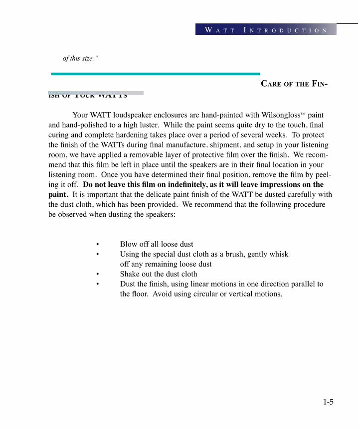
Your WATT loudspeaker enclosures are hand-painted with Wilsongloss™ paint and hand-polished to a high luster. While the paint seems quite dry to the touch, final curing and complete hardening takes place over a period of several weeks. To protect the finish of the WATTs during final manufacture, shipment, and setup in your listening room, we have applied a removable layer of protective film over the finish. We recom-mend that this film be left in place until the speakers are in their final location in your listening room. Once you have determined their final position, remove the film by peel-ing it off. Do not leave this film on indefinitely, as it will leave impressions on the paint. It is important that the delicate paint finish of the WATT be dusted carefully with the dust cloth, which has been provided. We recommend that the following procedure be observed when dusting the speakers:
• Blowoffallloosedust • Usingthespecialdustclothasabrush,gentlywhisk off any remaining loose dust • Shakeoutthedustcloth • Dustthefinish,usinglinearmotionsinonedirectionparallelto thefloor.Avoidusingcircularorverticalmotions.
W a T T i n T r o d u C T i o n
1-6
Because the paint requires a period of several weeks to fully cure, we recommend that no cleaning fluids such as glass cleaners be used during this initial period of time. When the paint is fully cured, heavy finger prints and other minor smudges may be removed with a glass cleaner. Always use the dust cloth. Stronger solvents are not recommended under any circumstances. Consult your dealer for further information if required. Periodic polishing may be desired over the years to maintain the high luster of the finish. We recom-mend a non-abrasive carnuba-based wax and soft cloth.
connecTion oF your WATT sPeAkers
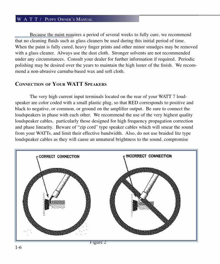
The very high current input terminals located on the rear of your WATT 7 loud-speaker are color coded with a small plastic plug, so that RED corresponds to positive and black to negative, or common, or ground on the amplifier output. Be sure to connect the loudspeakers in phase with each other. We recommend the use of the very highest quality loudspeaker cables, particularly those designed for high frequency propagation correction and phase linearity. Beware of “zip cord” type speaker cables which will smear the sound from your WATTs, and limit their effective bandwidth. Also, do not use braided litz type loudspeaker cables as they will cause an unnatural brightness to the sound, compromise
Figure 2
W a T T / puppy oWner’s manual

1-7
W a T T i n T r o d u C T i o n
sound staging performance, and may cause instability, oscillation and damage in wide bandwidth solid state amplifiers.
The spade lugs of some of the high quality cables often used with the WATT/Puppy are angled to reduce pressures on the cable during installation. Avoid the instinct to push the cable’s spade lug ends all the way into the WATT/Puppy’s connectors (see figure 2 ). Partial insertion of these angled spade lugs will actually improve the reli-ability of the connection. Flat lugs may be fully insert to connectors before tightening.selecTion oF inTerchAgeAble Tuning PorTs
The damping factor of an amplifier is a function of the amplifier’s output imped-ance into a given load impedance. Solid state amplifiers, due to their intrinsically low output impedance, tend to have a higher damping factor than vacuum tube amplifiers. Vacuum tube amplifiers typically are transformer-coupled in their output stage and the secondary windings of the output transformer present a relatively high source imped-ance. This source impedance is a parameter which must be considered in the tuning of the air volume of the loudspeaker enclosure. An interesting theoretical consideration is that if a loudspeaker is designed around a solid state amplifier and then used with a vacuum tube amplifier, it will tend to sound loose and tubby in the mid-bass regions. The WATT loudspeaker system allows you to precisely tailor the air volume tuning of the enclosure to the amplifier of your choice.
Your WATT loudspeaker comes equipped with two sets of interchangeable tun-ing ports. The ports connect on the back of the loudspeaker system and are affixed with three (3) button-head stainless steel screws. An allen key is provided which can be used to remove these screws to facilitate exchange of the ports. Typically, WATTs are shipped with the “D.F. 100-400” ports installed. This range encompasses the major-ity of high performance solid state amplifier types. Most vacuum tube amplifiers have damping factors of from 20 to 80, and we recommend the port which is labeled “D.F. 20-80.”
T E C H N I C A L N O T E
MounTing heighTs
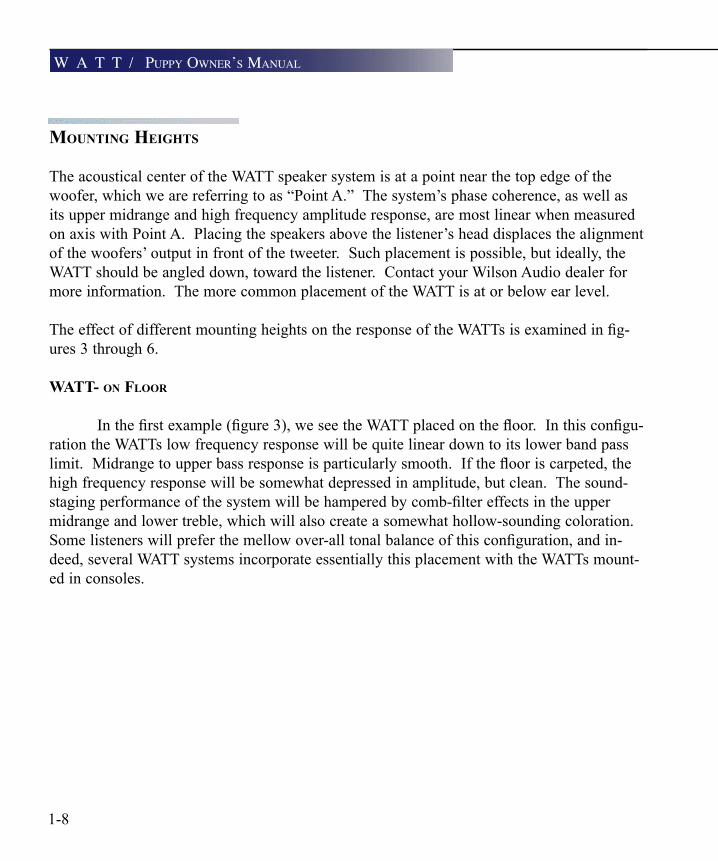
The acoustical center of the WATT speaker system is at a point near the top edge of the woofer, which we are referring to as “Point A.” The system’s phase coherence, as well as its upper midrange and high frequency amplitude response, are most linear when measured on axis with Point A. Placing the speakers above the listener’s head displaces the alignment of the woofers’ output in front of the tweeter. Such placement is possible, but ideally, the WATT should be angled down, toward the listener. Contact your Wilson Audio dealer for more information. The more common placement of the WATT is at or below ear level.
TheeffectofdifferentmountingheightsontheresponseoftheWATTsisexaminedinfig-ures 3 through 6.
WATT- on Floor
Inthefirstexample(figure3),weseetheWATTplacedonthefloor.Inthisconfigu-ration the WATTs low frequency response will be quite linear down to its lower band pass limit.Midrangetoupperbassresponseisparticularlysmooth.Iftheflooriscarpeted,thehigh frequency response will be somewhat depressed in amplitude, but clean. The sound-stagingperformanceofthesystemwillbehamperedbycomb-filtereffectsintheuppermidrange and lower treble, which will also create a somewhat hollow-sounding coloration. Somelistenerswillpreferthemellowover-alltonalbalanceofthisconfiguration,andin-deed, several WATT systems incorporate essentially this placement with the WATTs mount-ed in consoles.
1-8
W a T T / puppy oWner’s manual

Figure 3
1-9
W a T T i n T r o d u C T i o n
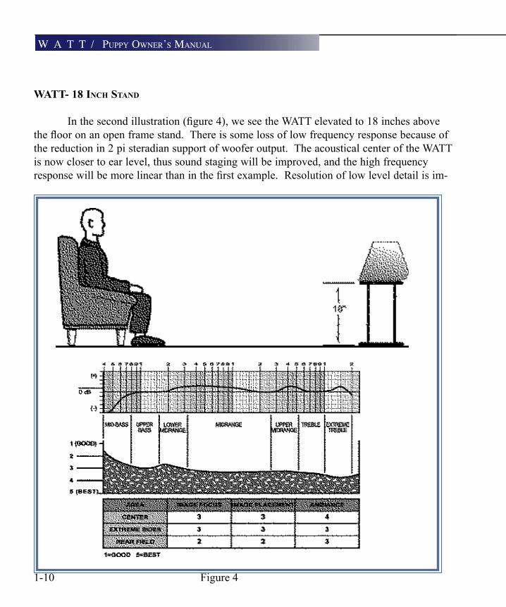
Figure 41-10
W a T T / puppy oWner’s manual
WATT- 18 inch sTAnd
Inthesecondillustration(figure4),weseetheWATTelevatedto18inchesabovetheflooronanopenframestand.Thereissomelossoflowfrequencyresponsebecauseofthe reduction in 2 pi steradian support of woofer output. The acoustical center of the WATT is now closer to ear level, thus sound staging will be improved, and the high frequency responsewillbemorelinearthaninthefirstexample.Resolutionoflowleveldetailisim-

WATT-24 inch sTAnd
Thethirdillustration(figure5),showstheeffectsofthespeakerbeingraisedanaddi-tional6inchesoffthefloor.Herethesoundstagingpropertieswillbeexcellentaswillhighfrequency linearity and overall lucidity of detail. There will, however, be a noticeable loss in bass and lower midrange response due to the lack of 2 pi steradian support of the direct outputofthewoofer.Generally,astheWATTisraisedupoffthefloor,thesoundbecomes“lighter” in balance as the speaker’s height is increased. The recommended range of mount-ing heights is from 18 inches to 28 inches.
1-11Figure 5
W a T T i n T r o d u C T i o n
WATT on PuPPy
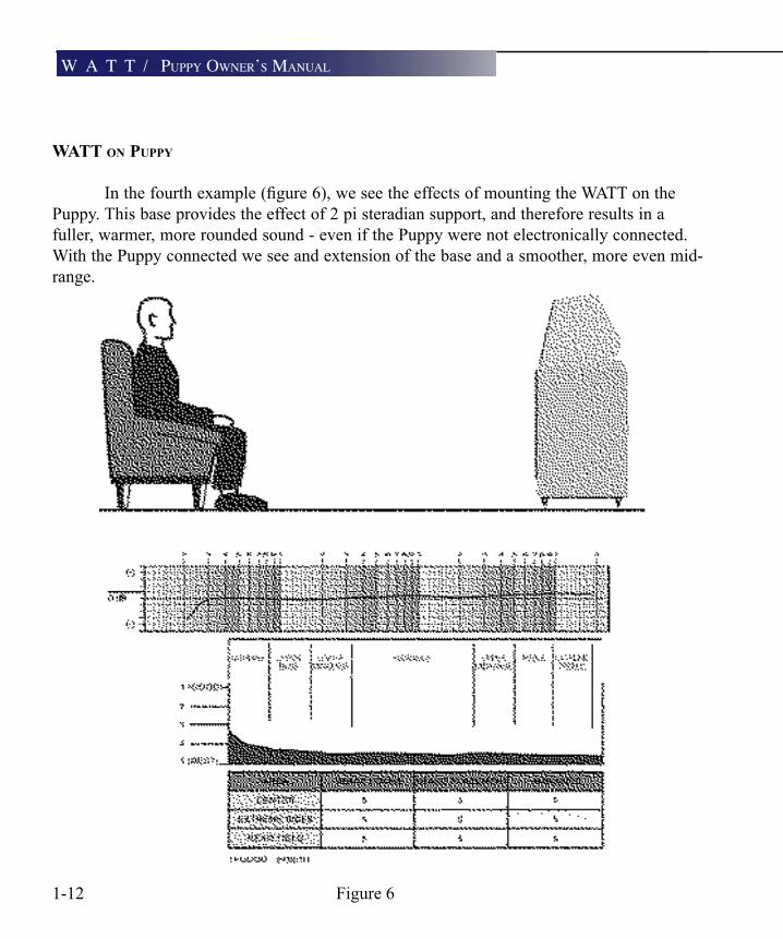
Inthefourthexample(figure6),weseetheeffectsofmountingtheWATTonthePuppy. This base provides the effect of 2 pi steradian support, and therefore results in a fuller, warmer, more rounded sound - even if the Puppy were not electronically connected. With the Puppy connected we see and extension of the base and a smoother, more even mid-range.
Figure 61-12
W a T T / puppy oWner’s manual
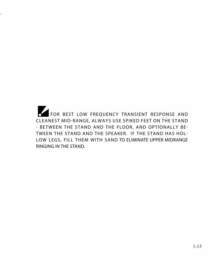
for beST loW frequency TrAnSienT reSponSe And cleAneST mid-rAnge, AlWAyS uSe Spiked feeT on The STAnd - beTWeen The STAnd And The floor, And opTionAlly be-TWeen The STAnd And The SpeAker. if The STAnd hAS hol-loW legS, fill Them WiTh SAnd To eliminATe upper midrAnge ringing in The STAnd.
1-13


2p u p p y IntroductIon

2-1
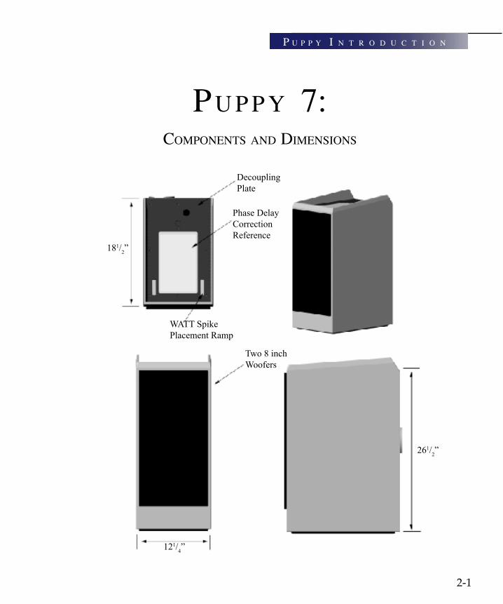
pu p p y 7:ComponenTs and dimensions
181/2”
121/4”
WATT Spike Placement Ramp
Decoupling Plate
Phase Delay Correction Reference
Two 8 inchWoofers
261/2”
p u p p y i n T r o d u C T i o n
cAbineT design
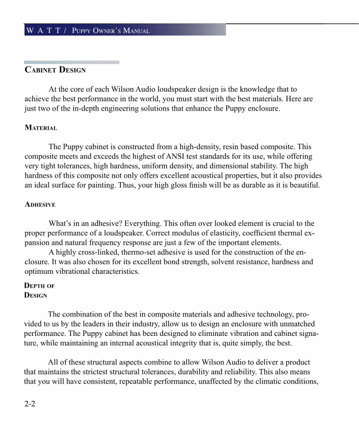
At the core of each Wilson Audio loudspeaker design is the knowledge that to achieve the best performance in the world, you must start with the best materials. Here are just two of the in-depth engineering solutions that enhance the Puppy enclosure.
MATeriAl
The Puppy cabinet is constructed from a high-density, resin based composite. This composite meets and exceeds the highest of ANSI test standards for its use, while offering very tight tolerances, high hardness, uniform density, and dimensional stability. The high hardness of this composite not only offers excellent acoustical properties, but it also provides anidealsurfaceforpainting.Thus,yourhighglossfinishwillbeasdurableasitisbeautiful.
AdhesiVe
What’s in an adhesive? Everything. This often over looked element is crucial to the properperformanceofaloudspeaker.Correctmodulusofelasticity,coefficientthermalex-pansion and natural frequency response are just a few of the important elements.
A highly cross-linked, thermo-set adhesive is used for the construction of the en-closure. It was also chosen for its excellent bond strength, solvent resistance, hardness and optimum vibrational characteristics.
dePTh oF design
The combination of the best in composite materials and adhesive technology, pro-vided to us by the leaders in their industry, allow us to design an enclosure with unmatched performance. The Puppy cabinet has been designed to eliminate vibration and cabinet signa-ture, while maintaining an internal acoustical integrity that is, quite simply, the best.
All of these structural aspects combine to allow Wilson Audio to deliver a product that maintains the strictest structural tolerances, durability and reliability. This also means that you will have consistent, repeatable performance, unaffected by the climatic conditions,
2-2
W a T T / puppy oWner’s manual

originAl design considerATions
The original Puppy high speed woofer was introduced in 1988, two years after thefirstWATT,seriesI.PriortothePuppy,usersoftheWATTwhodesiredmorelowfrequency extension, would add various subwoofers from other manufacturers. The results were unpredictable and often compromised overall musical performance. It be-came clear to Mr. Wilson that none of these subwoofers provided the speed necessary to blend seamlessly with the lightning-quick WATT.
Thus, in the initial design phase of the Puppy, Wilson concluded that what was needed was a highly articulate, low distortion, non-resonant, compact high-speed woofer with robust power handling, high sensitivity and excellent reliability. In every series of puppy, two very high quality low-frequency drivers are driven in parallel in a rigidly cross-braced, tuned enclosure to quickly dampen spurious resonances in the structure. ThecrossovernetworkinthebaseofthePuppyisalwayscomposedofthefinestaudiograde components, held to tolerances better than 0.1%.
PuPPy 7 .0
The System 7 Puppy employs a new woofer driver. Bass performance, especially in the areas of transient speed and frequency linearity, is notably im-proved over any previous generation Puppy. Bass extension into the bottom octave is also slightly enhanced. The Puppy 7’s bass performance is more con-sistent in a wider variety of rooms and environments.
2-3
p u p p y i n T r o d u C T i o n

2-4
T E C H N I C A L - N O T E
If the user wishes to test the polarity of the Puppy 7 with a battery, the plus (+) terminal of the battery is connected to the RED (+) input terminal of the Puppy and the negative (-) terminal of the battery is connected to the BLACK (-) termi-nal of the Puppy. The results of this test will show the Puppy woofers to move outward. This is the correct driver movement in response to a D.C. signal.
cAre oF The Finish oF your PuPPy
ThestandardfinishofyourPuppyisWilsonglossTM paint. Painted Puppys should be treated as described in the section on Care of the Finish of Your WATTs (page 1-5). Do not, under any circumstances, use organic solvents.
W a T T / puppy oWner’s manual

2-5
This page intentionally left blank
p u p p y i n T r o d u C T i o n


3i n y o u r r o o m

3-1
rooM reFlecTions
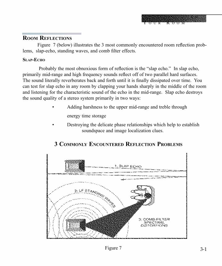
Figure7(below)illustratesthe3mostcommonlyencounteredroomreflectionprob-lems,slap-echo,standingwaves,andcombfiltereffects.
slAP-echo
Probablythemostobnoxiousformofreflectionisthe“slapecho.”Inslapecho,primarilymid-rangeandhighfrequencysoundsreflectoffoftwoparallelhardsurfaces.Thesoundliterallyreverberatesbackandforthuntilitisfinallydissipatedovertime.Youcan test for slap echo in any room by clapping your hands sharply in the middle of the room and listening for the characteristic sound of the echo in the mid-range. Slap echo destroys the sound quality of a stereo system primarily in two ways:
• Addingharshnesstotheuppermid-rangeandtreblethrough
energy time storage
• Destroyingthedelicatephaserelationshipswhichhelptoestablish soundspace and image localization clues.
Figure 7
3 coMMonly encounTered reFlecTion ProbleMs
i n y o u r r o o m

Non-parallel walls do not support slap echo, but rather allow the sound to diffuse.
Slap echo is a common acoustical problem in the typical domestic listening room, be-causemostoftheseroomshavewallsofahard,reflectivenature,usuallybeingonlyoc-casionally interrupted by curtains or drapes. Slap echo can be controlled entirely by the application of absorptive materials to hard surfaces, such as:
• Sonex
• Airductboard
• Corkpanels
• Largeceilingtofloordrapes
• Carpetingtowallsurfaces
In many domestic listening environments, heavy stuffed furnishings are the primary structural control to slap echo. Unfortunately, their effectiveness is not predictable. Dif-fusers are sometimes also used to very good subjective effect, particularly in quite large rooms. Sound absorbent materials such as described above will alter the tonal charac-teristic of the room by making it sound “deader,”much heavier in bass tonal balance, less “bright and alive” and “quieter.” These changes usually make the room more pleas-ant for conversation, but sometimes render it too dull in the high frequencies to be mu-sically involving. Diffusers, on the other hand, tend to not change the high frequency tonal balance characteristic of the room, but make the sound more “open”. A combina-tion of absorbtive and diffusive treatments is usually the best approach.
sTAnding WAVes
Anothertypeofreflectionphenomenonis“standingwaves”.Standingwavescause the unnatural boosting of certain frequencies, typically in the bass, at certain dis-creet locations in the room. A room generating severe standing waves will tend to make a loudspeaker sound one way when placed in one location and entirely different when placed in another. The effects of standing waves on a loudspeaker’s performance are primarily, as follows:
• Tonal balance-Bass too heavy
• Low-leveldetail-MaskedbylongreverationtimeLFstanding waves
3-2
W a T T / puppy oWner’s manual
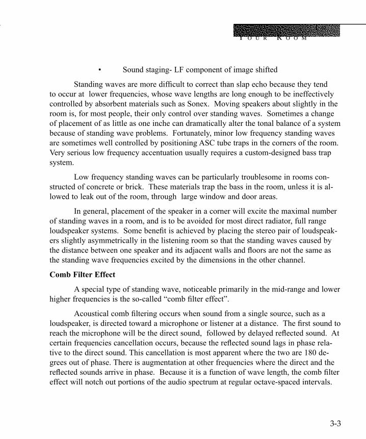
• Soundstaging- LF component of image shifted
Standingwavesaremoredifficulttocorrectthanslapechobecausetheytendto occur at lower frequencies, whose wave lengths are long enough to be ineffectively controlled by absorbent materials such as Sonex. Moving speakers about slightly in the room is, for most people, their only control over standing waves. Sometimes a change of placement of as little as one inche can dramatically alter the tonal balance of a system because of standing wave problems. Fortunately, minor low frequency standing waves are sometimes well controlled by positioning ASC tube traps in the corners of the room. Very serious low frequency accentuation usually requires a custom-designed bass trap system.
Low frequency standing waves can be particularly troublesome in rooms con-structed of concrete or brick. These materials trap the bass in the room, unless it is al-lowed to leak out of the room, through large window and door areas.
In general, placement of the speaker in a corner will excite the maximal number of standing waves in a room, and is to be avoided for most direct radiator, full range loudspeakersystems.Somebenefitisachievedbyplacingthestereopairofloudspeak-ers slightly asymmetrically in the listening room so that the standing waves caused by thedistancebetweenonespeakeranditsadjacentwallsandfloorsarenotthesameasthe standing wave frequencies excited by the dimensions in the other channel.
Comb Filter Effect
A special type of standing wave, noticeable primarily in the mid-range and lower higherfrequenciesistheso-called“combfiltereffect”.
Acousticalcombfilteringoccurswhensoundfromasinglesource,suchasaloudspeaker,isdirectedtowardamicrophoneorlisteneratadistance.Thefirstsoundtoreachthemicrophonewillbethedirectsound,followedbydelayedreflectedsound.Atcertainfrequenciescancellationoccurs,becausethereflectedsoundlagsinphaserela-tive to the direct sound. This cancellation is most apparent where the two are 180 de-grees out of phase. There is augmentation at other frequencies where the direct and the reflectedsoundsarriveinphase.Becauseitisafunctionofwavelength,thecombfiltereffect will notch out portions of the audio spectrum at regular octave-spaced intervals.
i n y o u r r o o m
3-3
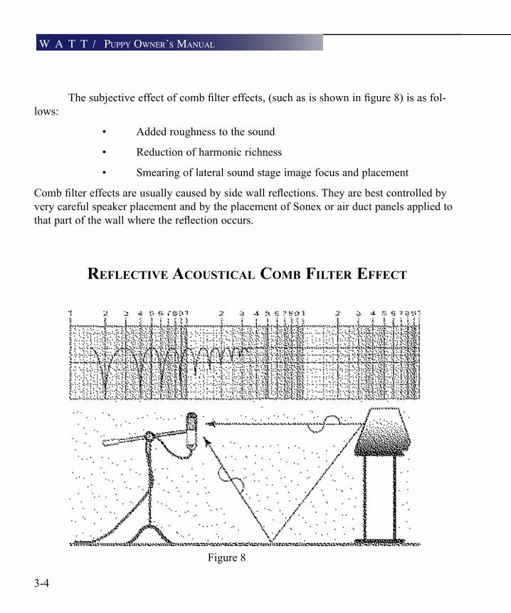
reFlecTiVe AcousTicAl coMb FilTer eFFecT
Figure 8
Thesubjectiveeffectofcombfiltereffects,(suchasisshowninfigure8)isasfol-lows:
• Addedroughnesstothesound
• Reductionofharmonicrichness
• Smearingoflateralsoundstageimagefocusandplacement
Combfiltereffectsareusuallycausedbysidewallreflections.Theyarebestcontrolledbyvery careful speaker placement and by the placement of Sonex or air duct panels applied to thatpartofthewallwherethereflectionoccurs.
3-4
W a T T / puppy oWner’s manual
resonAnces
Resonances in listening rooms are generally caused by two sources:
• Thestructureswithinthelisteningroom
• ThevolumeoftheairitselfinthelisteningroomsTrucTurAl resonAnces
Structural resonances are familiar to most people as buzzes and rattles, but this type of resonance usually only occurs at extremely high volume levels, and is usually masked by the music. In many wood frame rooms, the most common type of structural resonance problemis“booming”ofwallsandfloors.Youcantestfortheseveryeasilybytappingthewallwiththeheelofyourhandorstompingonthefloor.Ifitisawoodenfloor,thisisdone to detect the primary spectral center of the resonance. To give you an idea of what the perfect wall would sound like, imagine rapping your hand against the side of a mountain. Structural wall resonances generally occur in the low to mid-bass frequencies and add tonal balance fullness to any system played in that room. They too are more prominent at louder levels, but their contribution to the sound of the speaker is more progressive. Rattling windows, picture frames, lamp shades, etc. can generally be silenced with small pieces of caulk or with blocks of felt. Short of actually adding additional layers of sheet rock or book shelves,toflimsywalls,however,thereislittlethatcanbedonetoeliminatewallresonanc-es.
Air VoluMe resonAce
The volume of air in a room will also resonate at a frequency determined by the size of the room. Larger rooms will resonate at a lower frequency than will smaller rooms. Air volume resonances, wall panel resonances, and low frequency standing waves, together, combine to form a low frequency coloration in the sound. At its worst, it is a grossly exag-gerated fullness, which tends to obscure detail and distort the natural tonal balance of the speaker system. Occasionally, however, there is just enough resonance to give a little added warmth to the sound... an addition some listeners prefer. Tube traps manufactured by the ASC corporation have been found to be effective in reducing some of these low frequency room colorations. While custom designed and constructed bass traps, such as perforated Helmholtz resonators, provide the greatest degree of low frequency control.
i n y o u r r o o m
3-6
rooM shAPes
There are three basic shapes for most rooms: square, rectangular, and L-shaped (see Figure9).Aperfectlysquareroomisthemostdifficultroominwhichtosetupspeakersbe-cause, by virtue of its shape, square rooms are the perfect medium for building and sustaining standing waves. Standing waves are pressure waves created by the integration of sound and opposing,parallelwallswhichaccentuateparticularfrequencies.Theyheavilyinfluencethemusic played by loudspeakers, greatly diminishing the quality of the listening experience.
Long, narrow rectangular rooms also pose their own special acoustical problems for speaker setup. They have the ability to set up several standing wave nodes, which will have different frequency exaggerations depending on where you are sitting. Additionally, these long rooms are often quite lean in the bass near the center of the room. Rectangular rooms are still preferred to square rooms because by having two sets of dissimilar length walls, standing waves are not as strongly reinforced and will dissipate more quickly than in a square room. In these rooms the preferred speaker position for spatial placement and midrange reso-lution would be on the longer walls. Bass response would be reinforced, albeit not predict-ably, by speaker placement on the short walls.
In many cases L-shaped rooms offer the best environment for speaker setup. Ideally speakersshouldbesetupalongtheprimary(longest)legoftheroom.Theyshouldfirefromthe end of the leg (short wall) toward the bend, or they should be along the longest wall, with thespeakerfurthesttothebendbeinginsideofthebend.Inthiswaybothspeakersarefiringthe same distance to the back wall. The asymmetry of the walls in L-shaped rooms resists the buildup of standing waves.
W a T T / puppy oWner’s manual

i n y o u r r o o m
3-7
coMMon rooM shAPes:
optImum Speaker placementS
Figure 9

eFFecTs oF rooM PlAceMenT
The WATT/ Puppy System 7s were designed to be aimed at the listener, which means that they will be toed-in prominently rather than facing straight ahead. The illus-trations to follow will give examples of many common scenarios to assist you in the set up procedure.
The effect of room placement of the performance of the WATT is illustrated in figures10,11,and12.
corner Vs . in rooM PlAceMenT (no Toe)
Figure 10 examples 1A and 1B and table 4 compare the performance of cor-ner situated WATTs vs WATTs which are placed out in the room away from walls, but which are not toed-in. Placement of any direct full-range radiator loudspeaker in the corner results in numerous performance compromises. In one respect, however, corner placement of the speaker excels, and that is in low frequency augmentation. Looking at the tonal balance characteristic of the corner situated WATTs we can see an elevated lower midrange through mid bass region, the expected effect of corner loading, coupled with a gradual roll-off of the upper octaves, the result of any sound absorbing materials on adjacent walls, and the off-axis listening position.
Thecornerplacedspeakersarealsosignificantlyfurtherawayfromthelistenerthan the speakers in example 1B. By its very nature, sound, when traveling through air, loses low-level detail with distance. Ideally, therefore, the listener should sit as close to the speakers as is comfortable. Moving the speakers out into the room at least three feet from the rear wall, and at least two feet from the side walls, provides a fairly dramatic level of improvement of sound staging performance and overall mid and upper octave balance. But still the example shows the speakers not toed in. The WATTs are designed for maximum phase coherence and pulse replication accuracy when they are aimed di-rectly at the listener or microphone.
3-8
W a T T / puppy oWner’s manual

i n y o u r r o o m
Figure 10 3-9

WATT- in rooM PlAceMenT (WiTh Toe)
Figure 11 shows the effect of toeing in the WATTs. The speakers in example 2 are in the same general room location as the speakers in 1B, but are toed in. When the WATTs are correctly toed in, the listener, when seated in the listening position, will just barely see the surface of the inner side panels of the WATTs. We can see that toeing in the speakers provides dramatic improvements in resolution of low level detail in the midrange as well as dramatic improvements in sound staging performance. It should be noticed that in the tonal balance curve in the table reveals irregularities in response in the upper bass through lower midrange. These are caused by standing waves and adja-centwallcombfiltereffects.Theperformanceindicatedinthetableisverypromising,and yet it is not really representative of the best performance of which the WATT is ca-pable.Anyspeakerwillbenefitfromappropriateacousticalroomtreatment.
Figure 11
3-10
W a T T / puppy oWner’s manual

WATT- in rooM PlAceMenT, WiTh Toe, And AcousTicAl TreATMenT
Letusnowgotofigure12,toseethebenefitsinperformancewhichcanbeachievedby modest acoustical treatment of the room. With the speakers in the same location as in figure11,wenotetheadditionoftubetrapsinthecornersofthelisteningroom,aswellasfoam or Sonex panels placed between and behind the speakers, against the back wall, as well as along the wall behind the listener and over to the side next to the listener. The tube traps can be seen to smooth out the performance of the upper bass and lower midrange, while at the same time not compromising low frequency extension. Slap echo is controlled by the sound absorbing panel on the wall behind the speakers in the center of the sound stage and by the two panels on the back wall behind the listener. These two room treat-ments, namely tube traps and judicious placement of sound absorptive panels, can elevate the sonic performance of virtually any speaker system in a typical domestic listening room.
Should the listening position be as far from the speakers as possible, even up against a back wall? Figure 12, position B shows the effect of being seated near a back wall, some distance from the speaker. We can see a dramatic increase in upper bass and mid bass out-put of the system, actually due to standing wave reinforcement near the back wall, as well as the expected high frequency roll off resulting in the longer air path of the sound to the listener.
It should be noted that, in comparison to other speaker systems, even this compro-mised level of sound staging performance and resolution of low level detail still represents very good performance indeed.
i n y o u r r o o m
3-11

Figure 123-12
W a T T / puppy oWner’s manual

i n y o u r r o o m
sPeAker PlAceMenT Vs . lisTening PosiTion
The location of your listening position is as important as the careful setup placement of your WATT/Puppy System 7 speakers in your room. The listening position should ideally be no more than 1.1 to 1.25 times the distance between the tweeters on each speaker. There-fore, in a long rectangular room of 12’ x 18’, if the speaker tweeters are going to be 9’ apart, you should be sitting 9’11’’ to 11’3’’ from the speaker. This would be about halfway down the long axis of the room. Experiment carefully for best low frequency response.
Some people place the speakers on one end and sit at the other end of the room. Needlesstosay,thiswillnotyieldthefinestsound.Carefullyconsideryourlisteningpositionfor optimal performance. Our experience has shown that any listening position which places your head closer than 14” to a room boundary will diminish the sonic results of your listen-ing.
choosing A lisTening PosiTion
Decide where you want your favorite listening position to be. Please remember that yourWATT/Puppyscanfillalmostanyroomwiththemostbeautifulsound.However,forthetimealigningadvantage,wewanttoensurethatyougetallthebenefitspossiblewiththegruop delay adjustment features that are built into this design. For this purpose we ask you to consider the following questions:
What is the main purpose of your WATT/Puppys? Is it for a listening room dedicated to2-channelaudio?Ifyes,youshouldchooseyourpositioncarefullytoyieldthefinestsound. Wilson Audio uses a formula: The distance between the tweeters of the two channel times 1.2 equals the distance you should sit from each loudspeaker.
For instance, if you measure the distance between the center of the left channel tweeter to the corresponding right channel tweeter and it is equal to 10 feet, multiply it by 1.2. This means that you should sit approximately12 feet from each WATT/Puppy channel.
Are your WATT/Puppys dedicated for a home theater?Are you going to sit on a couch, or will there be multiple rows of chairs?If it is a couch, you should center the loudspeakers on the center position of the
couch.Multiple rows of chairs - In this case you should calculate the 1.2 times equation on
your second row of seating. Now more people will enjoy the power of your WATT/Puppys.Do you still want to listen to 2 channel music at its highest quality? In this way you
can enjoy optimized sound from that second seat.
3-13
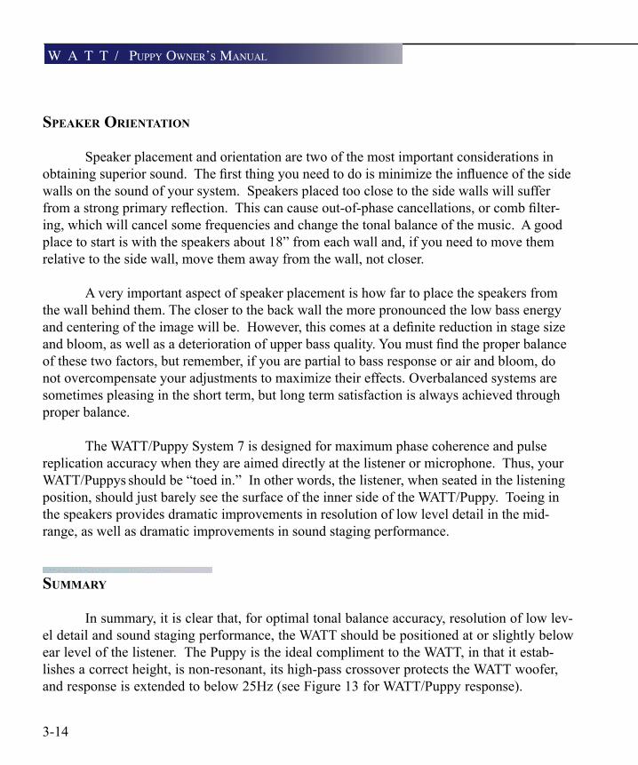
sPeAker orienTATion
Speaker placement and orientation are two of the most important considerations in obtainingsuperiorsound.Thefirstthingyouneedtodoisminimizetheinfluenceofthesidewalls on the sound of your system. Speakers placed too close to the side walls will suffer fromastrongprimaryreflection.Thiscancauseout-of-phasecancellations,orcombfilter-ing, which will cancel some frequencies and change the tonal balance of the music. A good place to start is with the speakers about 18” from each wall and, if you need to move them relative to the side wall, move them away from the wall, not closer.
A very important aspect of speaker placement is how far to place the speakers from the wall behind them. The closer to the back wall the more pronounced the low bass energy andcenteringoftheimagewillbe.However,thiscomesatadefinitereductioninstagesizeandbloom,aswellasadeteriorationofupperbassquality.Youmustfindtheproperbalanceof these two factors, but remember, if you are partial to bass response or air and bloom, do not overcompensate your adjustments to maximize their effects. Overbalanced systems are sometimes pleasing in the short term, but long term satisfaction is always achieved through proper balance.
The WATT/Puppy System 7 is designed for maximum phase coherence and pulse replication accuracy when they are aimed directly at the listener or microphone. Thus, your WATT/Puppys should be “toed in.” In other words, the listener, when seated in the listening position, should just barely see the surface of the inner side of the WATT/Puppy. Toeing in the speakers provides dramatic improvements in resolution of low level detail in the mid-range, as well as dramatic improvements in sound staging performance.
suMMAry
In summary, it is clear that, for optimal tonal balance accuracy, resolution of low lev-el detail and sound staging performance, the WATT should be positioned at or slightly below ear level of the listener. The Puppy is the ideal compliment to the WATT, in that it estab-lishes a correct height, is non-resonant, its high-pass crossover protects the WATT woofer, and response is extended to below 25Hz (see Figure 13 for WATT/Puppy response).
3-14
W a T T / puppy oWner’s manual

Ideally, the speakers should not be positioned too far from the listener, if maximum res-olutionoflowleveldetailisrequired(near-fieldmonitoring).Ifpossible,thespeakersshould be positioned out into the room, slightly asymmetrically away from side and rear walls. The speakers should be toed-in toward the listener, preferably so that the listener at his seated position can barely see the surface of the inner side panel of the WATT as he faces the speaker. It is recommended that a distance of 2-3 feet, and possibly more, be maintained between the WATT and the rear walls and a distance of at least 1 1/2 feet bemaintainedbetweenthefrontpaneloftheWATTandreflectivesidewalls.Useofsound absorbent materials may reduce the space requirement somewhat. Experiment for each room.
By following the guidelines in this manual and your own common judgement, your new WATT/Puppy speakers will provide you with a lifetime of pure music repro-duction.
i n y o u r r o o m
3-15
Figure 13

4W a T T / p u p -
p y s y s T e m 6 . 0 s e T u p


W a T T / p u p -p y s y s T e m 6 . 0 s e T u p
4-1
Note: Before setting up the Watt/Puppy System 7 study carefully the previous section on room acoustics. It provides valuable information on determing the ideal room location for your speakers.
PrePArATion
You will need the following items:
• Suppliedhardwarekit • Tapemeasure • Geometrictimingcharts(AppendixA) • Knownlisteningposition
Take a moment to familiarize yourself with the top of the Puppy. It contains informa-tion that will be needed during the setup (see Figure 14 below).
Figure 14
Watt SpikePlacement Ramp
Phase DelayCorrection Table
Painted Inner Edge
4-2
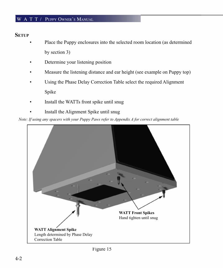
seTuP
• PlacethePuppyenclosuresintotheselectedroomlocation(asdetermined
by section 3)
• Determineyourlisteningposition
• Measurethelisteningdistanceandearheight(seeexampleonPuppytop)
• UsingthePhaseDelayCorrectionTableselecttherequiredAlignment
Spike
• InstalltheWATTsfrontspikeuntilsnug
• InstalltheAlignmentSpikeuntilsnug
Note: If using any spacers with your Puppy Paws refer to Appendix A for correct alignment table
Figure 15
WATT Alignment SpikeLength determined by Phase Delay Correction Table
WATT Front SpikesHand tighten until snug
W a T T / puppy oWner’s manual

W a T T / p u p -p y s y s T e m 6 . 0 s e T u p
4-3
• Carefully,placeWATTontospikeplacementrampontopofthePuppy about 3 inches from the front. Be careful not to damage the lower edges of the Watt or Puppy top
• GraspingthehandleandtopofWATT,slidetheWATTforwarduntil the spikes just slide off the ramp (see Figure 16 below)
Figure 16
Place Watt here

4-4
• Carefully,lowertherearoftheWATTontothedecouplingplate
• AdjustthepositionoftheWATTsoitiscenteredonthePuppy • Removetheprotectivefilm.Toremove,juststartattheedgeandpeelit
off.
Alignment Spike
Main input fromamplifier
Figure 17
W a T T / puppy oWner’s manual

W a T T / p u p -p y s y s T e m 6 . 0 s e T u p
4-5
PuPPy TAil connecTion
The correct connection of the Puppy Tail in the WATT/Puppy system 7 is:
• ConnecttheotherREDlugattheloadendofthetailtotheRED terminal on the WATT.
• ConnecttheotherBLACKlugattheloadendofthetailtotheBLACK terminal on the WATT.
Note: Please resist the temptation to invert the polarity of the Puppy Tail in the WATT/Puppy System 7. Such an inversion will produce entertaining ambient ef-fects, but destroys the linearity and harmonic structure of the system.

PuPPy PAWs
Included with your WATT/Puppy System 7 are two sets of Puppy Paws, which provide acoustical isolation as well as optimal height placement for your speakers. There are three ways of assembling the paws (without spacers, or with one or two spac-ers), and your choice will depend on your listening room and personal tastes. Wilson generally recommends no spacers, for simplicity and rigidity. However, the addition of spacerschangesthedriver-to-floordimension,andcansometimesbeusedtoreduceanobjectionable upper-bass/lower mid-range standing wave.
AsseMbly:
1. Insert either the short or the long threaded bolt, depending on the desired height (see figure18nextpage)asfarasitwillgointotheholeinthebottomofthePuppy.Make sure the Allen key end is accessable.
2. If desired, place the corresponding number of spacer discs over the bolt.
3. Screw the acoustical diode onto the bolt until it butts up against the spacers or Puppy bottom.
4. Screw the spike (with nut) all the way in until it just touches the bolt. Do not tighten the nut at this time.
5. Repeat steps 1 through 4 with the other three paws.
6.ToprovidethepropermechanicalcouplingbetweenthePuppyPawsandthefloor,make sure that the Puppy is level by unscrewing individual spikes as needed until even contact is achieved by all four Paws. A bubble level is often helpful in this procedure.
7. Once all adjustments have been made, tighten the nut on the spike to the diode with the 9/16” wrench provided. DO NOT OVERTIGHTEN! “Snug” is tight enough.
4-6
W a T T / puppy oWner’s manual

Pu P P y PA W s
AsseMbly diAgrAM
Figure 18
Option 1(0-1 Spacers)
Option 2(2 Spacers)
Lock Nut
1.5 inch Setscrew
OptionalSpacer
Spike
Diode
2 Spacers
2 inch Setscrew
Allen Key End of Setscrew
4-7
W a T T / p u p -p y s y s T e m 6 . 0 s e T u p

5W a T T / p u p p y s y s T e m 7 T a b l e s

5-1

5-2
