willys jeep cj3a 1948 manual
DESCRIPTION
WILLYS Jeep Cj3a 1948 ManualTRANSCRIPT


Lock Your Car
Your Jeep is equipped with an IgnitionLock to protect it against theft.
Locking is a part of parking. The igni-tion switch is operated by a key which
should be removed after turning offthe ignition.
CAUTION: Every owner should recordthe number of the ignition lock key so
that in case the keys are lost others maybe obtained by number. See Page 6.
PDF created with pdfFactory trial version www.pdffactory.com

Willys-Overland
OWNER’S MANUAL
Universal JeepModel CJ-3A
FIRST EDITION
Copyright 1948
Willys-Overland Motors
Willys-Overland Export CorporationToledo, Ohio, U. S. A
PDF created with pdfFactory trial version www.pdffactory.com


3
ForewordIN YOUR possession is a motor vehicle that has been thoroughly tested and inspected. Like any other piece of machinery, tomaintain it in first class condition, you should lubricate it at the time prescribed with the proper grade of oil and grease and keepall working parts and oil holes clean and free from dirt and grit. You should also periodically have it systematically inspected atan Authorized Willys-Overland Service Station.
In the following pages we have set forth the knowledge every owner should have of his vehicle, that he may know how to takethe best care of it and handle it in such a way that he will get maximum service. Information is also made available coveringexternal adjustments and minor emergency repairs. Read and follow these instructions carefully; we are sure that you will thenenjoy the satisfactory operation that you rightfully anticipate.
Should adjustment or repair seem necessary beyond your ability, don’t experiment; have the work done by a competent repairman. It will always prove best and cheapest in the end to have the work done by the Dealer from whom you purchased your car.Many Willys-Overland Dealers have factory trained mechanics and all are familiar with the construction and adjustments throughthe cooperation of the Manufacturer.
Do not attempt any adjustments as long as the vehicle is operating satisfactorily.
Be sure to obtain the Owner Service Policy, provided by your Dealer on delivery of your new vehicle.
CautionAccept and use only Genuine Factory Parts
Imitation parts are usually of inferior quality and can do serious damage to other mechanical parts of your vehicle.
Genuine parts are sold by all authorized Willys-Overland Dealers. Be sure none other than genuine parts are placed in yourvehicle.
Presence of parts other than those furnished by Willys-Overland will void the manufacturer’s Warranty.
NOTE: Parts replaced under the terms of the Warranty (Page 4) must be left with the Willys-Overland Dealer who makes thereplacement, if full credit is expected.
This is important for Owners to know, when traveling outside the territory in which their vehicle was originally purchased,particularly when credit for old parts cannot be established to the satisfaction of the Dealer.
In this connection, a forwarding address should be given by the Owner in order to insure the credit reaching him.
PDF created with pdfFactory trial version www.pdffactory.com

4
Standard Warranty
HE only Warranty under which new Willys-Overland Motor Vehicles are sold is that of the Manufacturer, being theStandard Warranty recommended by the Automobile Manufacturer’s Association, and is as follows:“This is to certify that we, WILLYS-OVERLAND MOTORS, INC., TOLEDO, OHIO, U.S.A. warrant each new motorvehicle manufactured by us, to be free from defects in material and workmanship under normal use and service, ourobligation under this Warranty being limited to making good at our factory any part or parts thereof, including all equipmentor trade accessories (except tires) supplied by the Car Manufacturer, which shall, within ninety (90) days after makingdelivery of such vehicle to the original purchaser or before such vehicle has been driven 4000 miles (6400 Km.), whicheverevent shall first occur, be returned to us with transportation charges prepaid, and which our examination shall disclose to oursatisfaction to have been thus defective; this warranty being expressly in lieu of all other warranties expressed or implied andof all other obligations or liabilities on our part, and we neither assume nor authorize any other person to assume for us anyother liability in connection with the sale of our vehicles. This warranty shall not apply to any vehicle which shall have beenrepaired or altered outside of an Authorized Willys-Overland Service Station in any way so as, in the judgment of theManufacturer, to affect its stability or reliability, nor which has been subject to misuse, negligence or accident.”
The Manufacturer makes no warranty against, nor assumes any liability for any defect in metal or other material in any part,device or trade accessory which cannot be discovered by ordinary factory inspection.
WILLYS-OVERLAND MOTORS, INC.
NOTE—Willys-Overland Motors, Inc., reserves the right at any time or times to revise, modify, discontinue or change anymodels of its vehicles, or any part or parts thereof, without notice; and, without it or the Seller, incurring any liability orobligation to the Purchaser.
T
PDF created with pdfFactory trial version www.pdffactory.com

5
General DataEngine—Model CJ-3A
Number of Cylinders 4Bore 3-1/8” 79.37 mm.Stroke 4-3/8" 111.12mmPiston Displacement 134.2 cu. in. 2199.53 ccCompression Ratio 6.48 to 1Horsepower SAE 15.6Horsepower Actual 60
Revolutions per minute 4000Torque ~Maximum Lbs. Ft 105 14.5 kg.m
Revolutions per minute 2000Wheelbase 80” 203.2 cm.Tread 48-1/4” 122.55 cmOverall Width 68-25/32” 174.703 cmOverall Height—Top up 69-7/32” 175.81 cm
—Top down 53-1/2" 135.89 cmOverall Length 126-25/32” 322.023 cmRoad Clearance 8-3/32" 20.556 cm*Weight Maximum Pay Load 800 lbs. 362.88 kg
Shipping (Less water, oil and fuel) 2110 lbs. 955.83 kgCurb (Including water, oil and fuel) 2203 lbs. 997.95 kgGross (Loaded) 3500 lbs. 1585.50 kg
*If equipped with aluminum full enclosure add 55 lbs. . (24.95 kg.)—ifaluminum cab only add 40 lbs. (18.14 kg.).Maximum Approved Draw Bar Pull (Continuous Operation) 1200 lbs. 544.32 kgFuel Tank Capacity 10.5 gals. 39.74 litersCooling System Capacity 11 qts. 10.41 liters
LAMP BULBS
Head Lamp (7 in. Sealed Beam Type) Upper Beam 45 watts Lower Beam 35 wattsParking Lamp Bulb 3 CP-SC- -No. 63Tail and Stop Lamp Bulb 21-3 CP-DC —No. 1158Instrument Lamp Bulb 2 CP-SC---No. 55.Fuse (Thermal Type)-—On Light Switch 30 AmperesLocation of Serial Number: Plate on right side of dash under hood.Location of Engine Number: Stamped on water pump boss.
PDF created with pdfFactory trial version www.pdffactory.com
6
InspectionYour Jeep was carefully lubricated and inspected at the factory and again thoroughly serviced by the Selling Dealer.
After your vehicle has been operated 1000 miles (1600 Km.) and also 2000 miles (3200 Km.), return it to yourDealer for the free inspections in accordance with Factory Service Policy. These inspections are free with theexception of engine oil and anti-freeze solution used.
Free Inspection1000 Mile (1600 Km.)
2000 Mile (3200 Km.)
Check steering system and front wheel alignment.Check spring clip nuts and spring shackles.Check rear axle for oil and leaks.Adjust body bolts.Test service and hand brakes—Inflate tires.Check cooling system for leaks and anti-freeze and fan belt adjustment.Adjust clutch pedal.
Check operation of transmission and transfer case—Check for oil level and leaks.Check battery, generator output, headlamps and horn.Tighten universal joint companion flange bolts.Check operation of ammeter, heat indicator, fuel and oil gauges.Tighten cylinder head nuts—Check timing and distributor points.Set spark plugs—Adjust carburetor—Check throttle controls.Check engine for oil leaks—Check fuel line connections.Adjust valve tappets, if required.Change engine oil (charge for oil)—Lubricate vehicle.Clean and refill, air cleaner.Clean fuel pump sump and strainer.Check extra equipment attaching screws—Check for oil level and leaks.
FILL IN FOR YOUR REFERENCE
Vehicle Serial Number
Engine Serial Number
Purchase Date
Ignition Key Number
PDF created with pdfFactory trial version www.pdffactory.com

7
SPECIAL PRECAUTIONSThere are several points of difference between the Universal Jeep and a conventional vehicle to receive attention. Asa general precaution and for your information we are listing these “cautions” below:
The Jeep is equipped with a transfer case and four-wheel drive to provide additional traction and a lower gear ratiofor use on difficult terrain. Use the front wheel drive only when necessary. Consider the front wheel drive and thetransfer case as a lower gear ratio than the standard transmission low gear and use it only when greater power isrequired.
The use of four-wheel drive on hard surfaced highways will result in rapid tire wear and hard shifting of the transfercase, particularly when the front wheels are steered even at a slight angle from the straight ahead position. If hardshifting occurs, disengage the clutch, start engine, shift transmission into reverse gear, back vehicle a few feet, anddisengage clutch. If transfer case is in low range, shift into high then shift front axle drive into “out” position (leverforward).
Two drain cocks are provided to drain the cooling system. A drain cock is located under the left side of the radiator,however, it is necessary to drain the cylinder block separately. The cylinder block drain is located at the right frontcorner of the block directly under the generator. Loosen the radiator filler cap to break the seal and permit completedraining.
Check the level of the lubricant often in the transmission and transfer case. Be sure the lubricant is at filler level inboth units at all times.
As a standard, the clutch pedal is adjusted with 114” (31.75 mm.) free travel. As the clutch wears this becomes less.Be sure that there is free travel at all times to prevent continuous operation of the clutch release bearing and rapidwear and slippage of the clutch. This adjustment is made by lengthening or shortening the clutch control cable.
The ventilator valve, mounted in the intake manifold, must be free to operate. If it is stuck open very uneven engineoperation at low speed will result.
Be sure the exhaust manifold heat control valve is free at all times and the thermostatic control spring is above thestop.
Six screws are used to attach the front wheel brake backing plate and spindle to the spindle housing. These screwsare standard in dimensions and thread pitch, however, they are made of special steel and receive special heattreatment. Safety demands that only genuine factory screws be used at this point.
PDF created with pdfFactory trial version www.pdffactory.com

8
Proper OperationDRIVING A NEW “JEEP”
Do not run your “Universal Jeep” faster than 40 miles an hour (64 Km. /h.) for the first 500 miles (800 Km.) or if used onthe farm or for industrial operation, use care when pulling heavy loads in the lower gear ratios. If the vehicle is operated athigh speeds while new or used for heavy pulling for a long period, the closely fitted parts might possibly becomeoverheated, resulting in scored pistons, cylinders or burned bearings. During its entire life, never race the engine whilemaking adjustments or when the vehicle is standing idle. If the vehicle is not properly lubricated, our Warranty is null andvoid. Be sure to have your Willys-Overland Dealer inspect your vehicle at the end of 1000 miles (1600 Km.) or equivalentusage and again at 2000 miles (3200 Km.).
TO MAKE VEHICLE READY.Fill the radiator with clean, soft water. Put gasoline in the tank.Fill the oil reservoir through the filler pipe at right side of engine until the oil indicator stick registers “FULL”. (See“Lubrication Chart”, Page 36). Supply all parts requiring lubrication with oil or lubricant.See that the tires have proper pressure (See Tire Pressure, Page 51).Adjust the rear view mirror to correct position for driver. If adequate view is not obtainable, the mirror may be adjusted byloosening the screw through the mounting bracket or by tilting in the ball and socket connection.
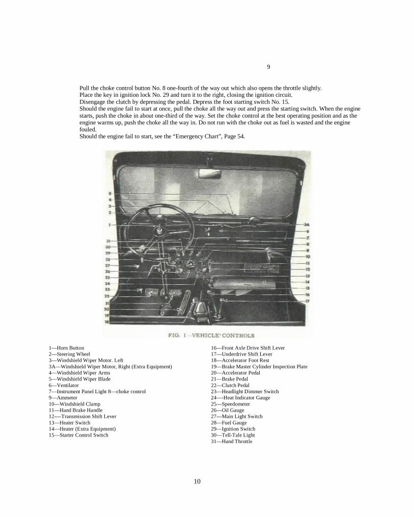
CONTROLS AND SWITCHESThe position of all controls and switches is shown in Fig. 1.The horn is operated by pressing the button located at the top center of the steering wheel.The main light switch No. 27 controlling all lights is conveniently located on the instrument panel to the left of the steeringpost. It is of the plunger type—pull all the way out for the “full on” position, half-way for “parking” and all the way in is the“off” position.In addition to the main light switch, the high and low beams of the head lamps are controlled by a selector foot switch, locatedon the toe board to the left of the clutch pedal. Pressing and releasing the switch button, with the foot, alternately changes thebeam from high to low and vice versa.
TO START ENGINEPut the transmission gearshift lever No. 12, Fig. 1 in neutral. Place the transfer case low and high shift lever No. 17 in directgear or in the rear position and disengage the front axle drive by placing the shift lever No. 16 in the forward position.
PDF created with pdfFactory trial version www.pdffactory.com
9
Pull the choke control button No. 8 one-fourth of the way out which also opens the throttle slightly.Place the key in ignition lock No. 29 and turn it to the right, closing the ignition circuit.Disengage the clutch by depressing the pedal. Depress the foot starting switch No. 15.Should the engine fail to start at once, pull the choke all the way out and press the starting switch. When the enginestarts, push the choke in about one-third of the way. Set the choke control at the best operating position and as theengine warms up, push the choke all the way in. Do not run with the choke out as fuel is wasted and the enginefouled.Should the engine fail to start, see the “Emergency Chart”, Page 54.
1—Horn Button 16—Front Axle Drive Shift Lever2—Steering Wheel 17—Underdrive Shift Lever3—Windshield Wiper Motor. Left 18—Accelerator Foot Rest3A—Windshield Wiper Motor, Right (Extra Equipment) 19—Brake Master Cylinder Inspection Plate4—Windshield Wiper Arms 20—Accelerator Pedal5—Windshield Wiper Blade 21—Brake Pedal6—Ventilator 22—Clutch Pedal7—Instrument Panel Light 8—choke control 23—Headlight Dimmer Switch9—Ammeter 24—-Heat Indicator Gauge10—Windshield Clamp 25—Speedometer11—Hand Brake Handle 26—Oil Gauge12-—Transmission Shift Lever 27—Main Light Switch13—Heater Switch 28—Fuel Gauge14—Heater (Extra Equipment) 29—Ignition Switch15—Starter Control Switch 30—Tell-Tale Light
31—Hand Throttle
10
PDF created with pdfFactory trial version www.pdffactory.com

FIG. 2 SIDE SECTIONAL VIEW OF ENGINE
1—Fan Assembly 2—Water Pump Bearing and Shaft Assembly3—Water Pump Seal Washer 4—Water Pump Seal Assembly5—Water Pump Impeller 6—Piston7—Wrist Pin 8—Thermostat Assembly9—Water Outlet Elbow 10—Thermostat Retainer11—Exhaust Valve 1 2—Intake Valve13—Cylinder Head 14—Exhaust Manifold Assembly15—Valve Spring 16—Valve Tappet Self-Locking Adjusting Screw17—Engine Plate—Rear 18—Camshaft19—Flywheel Ring Gear 20—Crankshaft Packing—Rear End21—Oil Pan 22—Crankshaft Bearing Rear Lower23—Valve Tappet 24—Crankshaft25—Oil Pump and Distributor Dtivc Gear 26—Connecting Rod Cap Bolt27—Oil Float Support 28—Oil Float Assembly29—Crankshaft Bearing Center—Lower 30—Connecting Rod Assembly—No. 231—Connecting Rod Bolt Nut 32—Crankshaft Bearing Front Lower33—Crankshaft Oil Passages 34—Crankshaft Thrust Washer35—Crankshaft Gear 36—Crankshaft Gear Spacer37—Timing Gear Cover Assembly 38—Fan and Generator Drive Belt39—Crankshaft Oil Seal 40—Crankshaft Nut41—Crankshaft Gear Key 42—Fan and Governor Drive Pulley Key43—Timing Gear Oil Jet 44—Fan. Generator and Governor Drive Pulley45—Camshaft Thrust Plate 46—Camshaft Gear Retaining Washer47—Camshaft Gear Retaining Screw 48—Camshaft Gear Thrust Plate Retaining Screw49—Camshaft Gear
PDF created with pdfFactory trial version www.pdffactory.com

11
TO START VEHICLE.Release hand brake, if set. Depress clutch pedal. Move transmission gearshift lever to first speed position—see Fig. 3. (Notethat the front axle and transfer case shift levers are not used when the vehicle is driven on the highway in rear wheel drive.)Depress the foot accelerator pedal gradually and at the same time, slowly release the clutch pedal. Allow the vehicle to gainmomentum (two or three vehicle lengths), then release the accelerator and depress the clutch pedal at the same moment.Move the shift lever promptly to the second speed position. Depress the foot accelerator pedal gradually and at the same time,slowly release the clutch pedal.Shift to third or “high” speed in the same way at approximately 18 to 20 mph (29-32 Km./h.), releasing the accelerator anddepressing clutch pedal before moving the shift lever.The synchronizing mechanism in the transmission makes gear shifting silent and easy. This device adjusts the speeds of thetwo gears to be engaged and prevents “clashing”.
TO CHANGE TO LOWER SPEED.Depress the clutch pedal.Move gearshift lever quickly in next lower speed, increase the engine speed slightly, if traveling on level road and release theclutch pedal.It will be found advisable to make this change when the engine is placed under heavy pull, or when dropping down to a verylow speed, as when traveling up a steep grade, in sand or in congested traffic.Never attempt to make the change with the vehicle traveling at a high rate of speed.
TO STOP THE VEHICLE.Release the foot accelerator.Depress the clutch pedal and apply foot brake.When stopped, move gearshift lever into neutral.Set the hand brake and release the clutch and brake pedals.
TO REVERSE VEHICLE.With vehicle at a standstill, depress the clutch pedal.Shift the gear lever into reverse position, slowly release the clutch pedal and regulate the car speed with the foot accelerator.
TO USE ENGINE AS A BRAKE.The most effective brake for holding the vehicle back on a steep grade is the engine. To use the engine as a brake, shift intoone of the lower speeds before starting to descend. Keep the clutch engaged, the throttle closed and the ignition “ON”. Lowgear will hold any vehicle effectively on any hill it can climb.
PDF created with pdfFactory trial version www.pdffactory.com

12
FIG. 4—END SECTIONAL VIEW OF ENGINE
1—Ignition Coil 2—Cylinder Head Gasket3—Exhaust Valve Guide 4—Intake Manifold Assembly5—Valve Spring Cover Assembly 6—Heat Control Valve7—Crankcase Ventilator Gasket 8—Exhaust Manifold Assembly9—Crankcase Ventilator Assembly 10—Distributor Shaft Friction Spring11—Oil Pump Driven Gear 12—Oil Pump Gasket13—Oil Pump Assembly 14—Oil Pump Pinion15—Oil Pump Cover 16—Oil Pump Relief ValveI 7—Oil Pump Relief Plunger Spring 18—Oil Pump Relief Plunger Shim19—Oil Pump Relief Plunger Spring Retainer 20—Oil Pump Shaft21—Oil Pan Assembly 22—Oil Pan Drain Plug23—Oil Float Support 24—Crankshaft Bearing Dowel25—Crankshaft Bearing Cap to Crankcase Screw 26—Oil Float Assembly27—Oil Filler Tube 28—Oil Filler Cap and Level Indicator29—Distributor Oiler 30—Distributor Assembly
PDF created with pdfFactory trial version www.pdffactory.com

13
Never engage the clutch suddenly when the vehicle is coasting with clutch released and the transmission gears in mesh, asdamage to the driving mechanism may result.
STARTING VEHICLE ON UPGRADE.In starting on an upgrade, hold the vehicle with the hand brake, disengage the clutch and shift the transmission into low speed,then accelerate the engine with the foot accelerator in the regular way while simultaneously releasing the hand brake andengaging the clutch.
SHIFTING GEAR IN TRANSFER CASE.The transfer case is essentially a two speed transmission, which provides a low and a direct gear and also a means ofconnecting the engine power to the front axle. It is an auxiliary unit attached to the rear of the standard transmission.Control of the transfer case is through the two shift levers, Fig. 1 No. 16 and No. 17. The left lever, No. 16, is used to connectand disconnect the power to the front axle. The right lever, No. 17 is used to shift the transfer case gears to secure either“High” (direct drive) or a very low gear ratio for heavy pulling requirements.Instructions for shifting gears in the transfer case and engagement of the front axle drive are as follows: See Fig. 3.
1. To engage front axle drive, depress the clutch pedal, release accelerator and move the left hand shift lever (No. 16) to rearposition.2. With the front axle drive engaged, the right hand lever (No. 17) may be shifted to the rear into “High” (direct) or forward into“Low”. The “Neutral” position midway between “High” and “Low” is for use when the power take-off belt drive is used. Thevehicle cannot be driven when this lever is in “Neutral”.3. To disengage the front axle drive, depress the clutch pedal, release the accelerator and shift the left lever to the forwardposition. The transfer case can be operated only in “High” (direct drive) when the front axle drive is disengaged.4. Shifting from high to low transfer case gear should not be attempted except when the vehicle is practically at a standstill. Thefront axle drive must be engaged for this shift. Release the accelerator and depress the clutch pedal—move the left hand shiftlever to the rear position to engage the front wheel drive, then move the right hand shift lever to forward position (low transfercase gear).5. Shifting from low to high transfer case gear may be accomplished at any time, regardless of vehicle speed. Release acceleratorand depress clutch pedal and shift right hand lever into rear position.USE OF FOUR WHEEL DRIVE.
The “Universal Jeep” is equipped with four-wheel drive and transfer case to provide additional traction and a lower gear ratiofor use on difficult terrain and to provide low speed pulling power for industrial and agricultural use. Four-wheel drive shouldbe used only when greater traction and power are required than that provided by the standard transmission low gear.Tire maintenance is of utmost importance when using four-wheel drive. Slight difference in the overall diameter of the frontand rear wheels will result in hard shifting. This difference may be caused by using a badly worn tire on one wheel and newtires on the others or by operating the vehicle with one or more of the tires underinflated.
PDF created with pdfFactory trial version www.pdffactory.com

14
Balance tire wear between the front and rear wheels as closely as possible. Keep tires inflated to recommendedpressure (Page 51) especially when operating the vehicle with maximum load.Avoid the use of four-wheel drive on hard surfaced highways as it will result in rapid tire wear and hard shiftingof the transfer case gears. Should hard shifting occur, disengage the clutch, start engine, shift the transmissioninto reverse gear, back the vehicle a few feet and disengage the clutch. If transfer case is in low range, shift intohigh, then disengage front axle drive (left lever forward).
STEERING KNUCKLE OIL SEAL.
When parkingduring cold, wetweather, swing the front wheels from right to left to wipe away moisture adheringto the front axle universal joint housings and oil seals, Fig. 5. This will prevent freezing with resulting damage tothe oil seal felts. When the vehicle is stored for any period, the front axle universal joint housings should becoated with light grease to prevent rusting.
FIG. 5—KNUCKLE OIL SEAL
How to Save Gasoline1. In cold weather economical starting of the engine is easily obtained by pressing down on the acceleratorpedal once or twice, then push down on the clutch pedal and start engine using the choke sparingly. Do not use thechoke when starting a warm engine.2. Do not use the choke excessively while engine is warming up and never leave it out longer than absolutelynecessary.3. Accelerate gently. Tramping on the accelerator pumps more• gasoline into the cylinders than can beeffectively used.4. Holding the car in second gear until you get up to high speeds may easily double the gasoline you shoulduse in getting under way. Shift into high gear at about 20 miles per hour (32 Km./h.).5. Fast driving uses up more gasoline. Travel at moderate speeds if you want gasoline economy.6. Decelerate to a gradual stop. Sudden stops, like sudden starts, are wasteful of gasoline.7. Park your car in the shade if possible, hot sun evaporates gasoline.8. Don’t drive your tires with less than the proper air pressure. Under-inflated tires mean more road friction,more work for the engine to do—and therefore more gasoline consumed. See “Tire Pressure” Page 51.9. Keep the battery charged up in good condition. It helps starting and provides good ignition therebyreducing loss of gasoline.10. Letting the engine idle for long periods wastes gasoline.11. Be sure that the carburetor is in proper condition for maximum mileage and power.
PDF created with pdfFactory trial version www.pdffactory.com

15
12. One faulty or dirty spark plug may waste as much as 10 per cent of your gasoline. Have the spark plugs testedoccasionally.13. Keep your car well lubricated at all times, and be very careful to follow the instructions on “Lubrication”.14. Keep the radiator filled to the proper level, your engine will remain at a more constant temperature. An overheatedengine uses more gasoline.15. Check the operation of the automatic heat control on the exhaust manifold. The purpose of this heater is to warm themixture of air and gasoline as it leaves the carburetor, in order to give better vaporization. (See Manifold Heat Control, Page 23.)16. It is a good idea to have a complete engine tune-up every 5,000 miles (8000 Km.), or at least twice a year—in the Fallwhen preparing for Winter driving and again in the Spring. The Owner Service Policy entitles you to an adjustment and completeinspection without charge at the end of the first 1000 miles (1600 Km.) and again at 2000 miles
(3200 Km.).
General LubricationThe use of high grade lubricants and regular application is specially essential when operating the “Jeep” because of thediversified service it performs. The amount of trouble free service received will be in proportion to the care given. Lubricatethe vehicle in accordance with the type of service performed.The following pages should be referred to for instructions covering grade and quantity of lubricant required for all parts of thevehicle. The mileage instructions should be followed when the vehicle is used for road work. It is impossible to give accuratehourly instructions because of the diversified service and conditions under which the vehicle may be operated. The hoursindicated are approximate. To obtain maximum service, good judgment must be used to lubricate the vehicle according to thetype of work being done. As an example—when used as a farm tractor under dusty conditions the chassis should be lubricateddaily as the new lubricant forces grit and. dirt, which has accumulated during the day, from the bearing surfaces. Under theseconditions, the air cleaner should also be cleaned and refilled daily or under extreme conditions twice daily.Because of the importance of correct lubrication, detailed recommendations, unit capacities and specifications are given in thefollowing paragraphs. Also refer to the Lubrication Chart on Page 36.
Lubrication SpecificationsType Winter Summer
Chassis Lubrication Chassis Grease No. 0 No. 1Transmission and Transfer Case Transmission Gear Oil SAE 80 SAE 90Differentials—Front and Rear Hypoid Gear Oil SAE 90 SAE 90Steering Gear Steering Gear Lubricant SAE 140 SAE 140Wheel Bearings Wheel Bearing Lubricant No. 2 No. 2Universal Joints (Front Axle Shaft) Universal Joint Lubricant No. 0 No. 1
or Chassis Grease No. 0 No. 1Universal Joints (Propeller Shaft) Chassis Grease No. 0 No. 1Power Take-Off Housing ... Hypoid Gear Oil SAE 80 SAE 80Air Cleaner . . . Engine Oil Same Grade used in engineGovernor . Engine Oil Same Grade used in engineEngine . Engine Oil See Below Above 90° F Not Lower than 32° F. As Low as +10° F. As Low as .~10° F. 32° C 0° C. -12° C. -23°C. SAE30 SAE20or30 SAE20W SAE10W For temperatures below —10° F. (-23° C.) use SAE 10 plus 10% kerosene or SAE 5 W.
PDF created with pdfFactory trial version www.pdffactory.com

16
Lubrication Capacities U. S. Imperial Metric
Engine Crankcase—oil filter empty (qts.) 5 4-1/2 4.73 litersTransmissionTransfer Case (pts.) 6-1/2 5-1/2 3.7 litersDifferential—Front Axle (pts.) 2-1/2 2 1.18 litersDifferential—Rear Axle (pts.) 2-3/4 2-1/4 1.30 litersOil Bath Air Cleaners (pts.) 1-1/4 1 591.40 CCBrake System Fluid (pts.) 3/4 5/8 354.84 CCPower Take-Off (pts.) 1 3/4 .473 litersPulley Drive Unit (pts ) 3/4 5/8 354.84 CC
ENGINE LUBRICATION.Lubrication of the engine is accomplished by means of a force-feed continuous circulating system. This is effected by meansof a rotor type pump, located externally on the left side of the engine, and driven by a spiral gear on the. camshaft.The oil is drawn into the circulating system through a floating oil intake. The floating intake does not permit water or dirt tocirculate, which may have accumulated in the bottom of the oil pan, because the oil is drawn horizontally from near the topsurface.An oil pressure gauge is mounted in the instrument panel, which indicates the pressure being supplied to the circulatingsystem. Failure of the gauge to register may indicate absence of oil, leakage or a fault in the lubrication system and the engineshould be stopped immediately. If there is plenty of oil in the reservoir the mechanical fault must be corrected before startingthe engine. Standard gauge reading is approximately 30 to 35 lbs. (5.355 to 6.247 Kg./cm.) at 30 miles per hour (48 Km./h.)and 5 to 10 (.892 to 1.785 Kg. /em.) at idle speed.The quantity of oil in the crankcase is measured by the bayonet type oil level indicator which is combined with the oil fillercap located in the oil filler pipe at the right side of the engine. When the oil level is below the “Full” mark, pour sufficient newoil into the reservoir to bring the level to the “Full” mark.When the vehicle leaves the factory the crankcase is filled to the correct level with oil of the proper viscosity for the “break-in”period. When the vehicle is used on the highway, completely drain the engine oil at 500 miles (800 Km.), and at 1000 miles(1600 Km.), then every 2000 miles (3200 Km.) thereafter, by removing the drain plug in the lower left side of the oil pan.Replace the drain plug and refill with 4 qts. (3.8 liters) (5 qts. [4.7 liters] when the oil filter has been drained) of fresh oil. Forheavy industrial or dusty field work, change the oil at the first 10 hours, and each 50 hours thereafter. To secure maximumengine life, watch the condition of the oil closely and should it become contaminated, due to the conditions under which thevehicle is being operated, change it immediately.Always drain the oil when the engine is warm. The benefit of draining is, to a large extent, lost if the crankcase is drainedwhen the engine is cold, as some of the foreign matter will remain in the bottom of the oil pan.At least once a year, preferably in the Spring, remove the oil pan and floating oil intake and wash thoroughly with cleaningsolution.
CHASSIS LUBRICATION.When lubricating the chassis refer to the Lubrication Chart on Page 36.For highway travel, clean and lubricate points indicated as No. 1 each1000 miles (1600 Km.). When used in industrial or agricultural work the
PDF created with pdfFactory trial version www.pdffactory.com

17
period for lubrication depends entirely upon the type of work being done. When doing dusty field work, lubricate these pointsdaily as grit and dirt will work into the bearing surfaces and cause rapid wear unless forced out by new lubricant.The importance of using a good grade of chassis lubricant can not be exaggerated, for the cost will be more than repaid bylonger wear and good service.
OIL FILTER.The oil filter should be dismantled, cleaned and the filter element replaced at the end of the first 2000 miles (3200 Km.) ofhighway travel, or 100 hours of industrial or field use. Drain the filter at each oil change to prevent the old oil contained in thefilter from mixing with and contaminating the new oil. Replace the element at each 8000 miles (12,800 Km.) of highwaytravel or 200 hours of industrial or field use.
AIR CLEANER.Care of the air cleaner is EXTREMELY IMPORTANT—especially when the vehicle is used under dusty conditions. Cleanand refill the air cleaner reservoir to the level mark, with oil of the same grade used in the engine, at each engine oil change.When the vehicle is used for field work, clean and change oil in the cleaner DAILY and under extremely dusty conditionsTWICE DAILY. When cleaning, use a long screw driver or other suitable tool to dislodge dirt sticking to the bottom and sidesof the intake passage in the body of the cleaner.
STEERING GEAR.Check the level of the lubricant in the steering gear housing every 1000 miles (1600 Km.). Avoid the use of cup grease,graphite, white lead or heavy solidified oil. Remove the plug in the steering gear housing and use a hand gun to fill thehousing slowly.
WATER PUMP- CLUTCH.The water pump bearing and clutch release bearing are prelubrieated at assembly and the lubricant lasts for the life of thebearings.
GENERATOR.Two oilers are provided, one at each end; three to five drops of engine oil is recommended every 1000 miles (1600 Km.). Besure to slip the commutator end hole cover back in place.
STARTING MOTOR.The oil hole cover on the commutator (front) end slips to one side; put three to five drops of engine oil in this hole every 1000miles (1600 Km.). Be sure to slip cover back in place.
IGNITION DISTRIBUTORThe oiler on the distributor should be lubricated every 1000 miles (1600 Km.) with several drops of engine oil, Fig. 7, No. 6.Also place one drop of light engine oil on the wick, No. 2 located in the top of the shaft, which is accessible by removing therotor arm and sparingly apply soft grease on the breaker arm cam No. 4, and a drop of oil on breaker arm pivot, No. 3.
SPEEDOMETER AND DRIVE.Remove the drive shaft from the tube once each year, clean it thoroughly and lubricate with a good quality light graphitegrease.
PDF created with pdfFactory trial version www.pdffactory.com

18
UNIVERSAL JOINTS (PROPELLER SHAFT).Every 1000 miles (1600 Km.) lubricate propeller shaft universal joints and slip joints with a good qualitylubricant. Lubricate daily for field work.
UNIVERSAL JOINTS (FRONT AXLE SHAFT).The front axle universal joints are inclosed in the steering knuckle housings which are filled with lubricant sorequire no attention other than checking each 1000 miles (1600 Km.) to be sure the housings are filled to pluglevel.Once each year (12,000 miles) (19,200 Km.) the axle shafts and universal joint assemblies should be removed,thoroughly cleaned and the housings filled with new lubricant. When the vehicle is used for dusty field work,clean and repack the housings twice each year.
POWER TAKE-OFF PROPELLER SHAFT UNIVERSAL JOINTS.For average service the original factory lubrication will last the life of the vehicle. If the power take-off is usedoften for continuous operation, disassemble and repack once each year.
WHEEL BEARINGS.Front wheel bearings should be removed, thoroughly cleaned, checked and repacked twice yearly or every 6,000miles (9600 Km.).
The rear wheel bearings are equipped with hydraulic lubricators. Lubricate them sparingly to guard againstsurplus oil saturating the brake lining. An oil relief hole at top of housing, Fig. 32, No. 1, indicates when thebearing is filled with oil.
TRANSMISSION AND TRANSFER CASE.Drilled passages are provided between the transmission and transfer case housings for circulation of thelubricating oil to provide unit lubrication of the two assemblies. Service each assembly individually. Check theoil level each 1000 miles (1600 Km.) or at each lubrication. Drain and refill at each 6000 miles (9600 Km.) or300 hours of field work.
Note: The requirements of these housings are small for economy, therefore, it is very important that the lubricant bechanged every 300 hours when the vehicle Es used for dusty field work.
FRONT AND REAR DIFFERENTIALS.The differential gears require extreme pressure lubricant, which is suitable for hypoid gear type axles. The levelof the lubricant in these units should be checked every 1000 miles (1600 Km.). Do not mix different types ofhypoid lubricants.Drain and refill the housings each 6000 miles (9600 Km.) or twice yearly. Use a light engine or flushing oil toclean out the housings.
Note: Do not use water, steam, kerosene, or gasoline for flushing. If the oil is decomposed, dismantling is necessary.
GOVERNOR.At each lubrication, check the oil level in the governor housing. Use oil of the same grade used in the engine tomaintain the lubricant at filler plug level. Drain and refill the housing at each engine oil change.
POWER TAKE-OFF SHAFT AND PULLEY DRIVE HOUSINGS.Check the lubricant level at each lubrication job, maintaining the lubricant at filler plug level. Should the powertake-off be used frequently, change the lubricant each 300 hours.
PDF created with pdfFactory trial version www.pdffactory.com

19
Proper Maintenance
NEVER RUN ENGINE IN CLOSED GARAGE
Due to the presence of carbon monoxide (a poisonous gas in the exhaust of the engine) never run the engine for any lengthof time while the vehicle is in a small closed garage. Opening the doors and windows will lessen the danger considerably,but it is safest if adjustments are being made that require the operation of the engine, to run the vehicle out-of-doors.
INSPECTION.The old adage “An ounce of prevention is worth a pound of cure” was never more true than when applied to anymotor vehicle. The importance of regular systematic inspection cannot be over-emphasized. Small and seeminglyunimportant faults, if neglected, may grow into expensive major repairs. Regular inspections and promptcorrection of small faults will go far toward holding down maintenance expense, eliminating delays in productiveoperations and upholding the high standard of reliability and performance built into your “Jeep” at the factory.In the following paragraphs are methods of making minor adjustments and preventive maintenance suggestions.Should major repair work be necessary, consult your Willys-Overland Dealer.
ENGINE TUNE-UP.For best performance and dependability the engine should have a periodic tune-up twice yearly, preferably in theSpring and Fall.Remove the spark plugs, clean them thoroughly and space the electrodes to .030” (0.76 mm.) gap.Clean and tighten the battery cable terminals, the battery ground connection and the ground strap, Fig. 10, on theright side of the engine at the front engine support.Remove the distributor cap and inspect the contact points. Adjust the points to .020” (0.51 mm.) gap. See Fig. 7,No. 5.Check the ignition timing.Check the valve tappet clearance. Adjust to .016” (0.406 mm.) clearance with engine hot or cold.Clean the fuel pump filter screen and check fuel line connections. Remove the ventilator valve, Fig. 12, and clean.Start the engine and allow it to run until thoroughly warm then set the carburetor idle screw so the engine will idleat 600 rpm (vehicle speed of approximately 6 mph (9.6 Km./h.).Adjust the carburetor low speed idle screw No. 15, Fig. 14, so that the engine will idle smoothly.
NOTE: Should the engine fail to perform satisfactorily and the trouble is definitely traced to the carburetor,consult your Willys-Overland Dealer. Carburetor service is specialized and should not be undertaken unless theunit is thoroughly understood.
PDF created with pdfFactory trial version www.pdffactory.com

20
VALVE AND IGNITION TIMING.Piston Measurements
From Top Center
Inlet opens 9 degrees before top center 039” (0.991 mm.)
Inlet closes 50 degrees after bottom center 3.772” (95.81 mm.)
Exhaust opens 47 degrees before bottom center. . . .3.799” (96.49 mm.)
Exhaust closes 12 degrees after top center 054” (1.37 mm.)
Ignition Timing 5° BTC
Spark set top center with automatic spark controls at rest, when using low octane fuel.
Firing Order 1-3-4-2
Tappet setting for valve timing 020” (0.51 mm.)
Number of flywheel teeth 124
CHECKING VALVE TIMING.
To check the valve timing, adjust the inlet valve tappet No. 1 cylinder to .020” (0.51 mm.). Use care in making this adjustmentthat the measurement is accurate with feeler gauges and that the tappet is resting against the lowest surface of the camshaftcam. Rotate crankshaft clockwise until piston in No. 1 cylinder is ready for the intake stroke. (The intake valve opens at 9°before top center. The flywheel is marked at top center and 5° before top center. Estimate the 9° position, as viewed throughthe timing hole opening, Fig. 6, in the flywheel housing on the right side of the engine, by noting distance between the topcenter mark and the 5° mark.) With the crankshaft in this position, valve timing is correct if No. 1 intake valve tappet is justtight against the end of the valve stem. After checking, adjust all of the tappets .0 16” (0.406 mm.). The correct alignment ofthe timing gear marks when setting valve timing is indicated in Fig. 8.Should the timing be incorrect it is advisable to consult your Willys-Overland Dealer.
FIG. 6—FLYWHEEL TIMING MARKS
PDF created with pdfFactory trial version www.pdffactory.com

21
IGNITION TIMING.
The breaker points should be cleaned and adjusted to .020” (0.51 mm.) opening. Remove all the spark plugs exceptNo. 1. Rotate the crankshaft until No. 1 piston is coming up on the compression stroke which can be determined bythe resistance in the cylinder. Remove the spark plug and continue to turn the engine slowly until the mark ~ on theflywheel is in the center of the timing hole in the flywheel housing at the right rear. This places the piston in thecorrect position to set the ignition.
Loosen the distributor clamp and rotate the distributor assembly until the distributor rotor arm points to No. 1terminal in the distributor cap and the distributor points just start to break. To advance the timing, turn the distributorin a clockwise direction; to retard it, turn in a counterclockwise direction. Tighten the clamp screw firmly but do notover-tighten it.
The engine firing order is 1-3-4-2.
After setting the timing, revolve the crankshaft two complete turns, to make sure all backlash is eliminated, andcheck the timing to the flywheel 5° mark.
Ignition timing must be accurately set to obtain maximum efficiency given only to enable the operator to place thevehicle back in service should trouble develop. At the first opportunity, have your Willys-Overland Dealer check thesetting with a neon timing lamp which can also be used to check the automatic spark advance operation, byaccelerating the engine.
FIG. 7—DISTRIBUTOR FIG. 8—TIMING GEAR MARKS1—Condenser2—Lubricating Wick3—Breaker Arm Pivot4—Breaker Cam5—Distributor Points6—Oiler7—Adjustment Lock Screw8—Adjusting Screw
PDF created with pdfFactory trial version www.pdffactory.com

22
ENGINE FAILS TO START.
Should the engine suddenly stop or fail to start, check the cause as follows. Also see “Emergency Chart” Page 54.
1. Make sure there is gasoline getting to the carburetor (Note: Should the trouble be traced to the gasoline supply see “FuelSystem” Page 28) and that the ignition switch is “ON”.
2. Check ignition circuit wiring connections to be sure they are tight and clean.
3. Be sure that the distributor breaker points are smooth, have a flat contact with each other and are set to the proper gap(.020”) (0.51 mm.). If the points are rough, replace them or temporarily smooth them with a breaker point file.
4. Inspect the distributor cap and rotor for cracks carbon runners or burned places. If they are found replace the part.
5. See that current is reaching the distributor breaker points. To make this test, turn on the ignition switch, remove thedistributor cap and turn the engine until the breaker points are open, then holding one end of a piece of wire on the breakerarm, strike the other end on a clean, unpainted surface of the engine. No flash indicates a poor or open connection betweenthe switch and distributor or an open circuit in the coil. If the wire and connections leading to the coil are in good condition,then an open primary in the coil is apparent and a new coil will be necessary.
If a flash occurs when testing the primary, as outlined above, it indicates that the primary circuit is all right and the trouble iselsewhere so the secondary coil circuit should be tested as follows:
FIG. 9—HEAT CONTROL VALVE FIG. FIG 10—ENGINE GROUND STRAP AND CONNECTIONS
1—Heat Control Valve Lever Key
2—Heat Control Valve Lever Clamp Bolt Nut
3—Heat Control Valve Shaft
4—Heat Control Valve Lever Clamp Screw
5—Heat Control Valve Hi-Metal Spring Washer
6—Heat Control Valve Counterweight Lever
7—Heat Control Valve Hi-Metal Spring
8-—Heat Control Valve Bi-Metal Spring Stop
PDF created with pdfFactory trial version www.pdffactory.com

23
6. To test the secondary coil circuit, remove the distributor cap and turn the engine until the breaker points are making contact.Turn “ON” the ignition switch and remove the high tension wire (center wire) from the distributor cap. Hold this wire about one-eighth of an inch from a clean, unpainted surface of the engine, then open and close the breaker points with the finger, givingthem a short, snappy break. A fat, flame-colored spark indicates the coil is in good condition. No spark indicates the secondarywinding of the coil is open, while a thin, stringy spark indicates an internally shorted coil or a loose or inoperative condenser.Condenser trouble will also be indicated by badly burned breaker points. Should the test show a thin stringy spark, check thecondenser first. Be sure that the mounting screw is tight and is making a good ground connection to the distributor body and alsothat the connecting wire to the distributor points is not broken or the connection loose. Should no trouble be found in thecondenser mounting or connection, install a new condenser which will localize the difficulty in either the coil or the condenser.No repairs can be made to either the condenser or coil, it being necessary to replace them if inoperative.
MANIFOLD HEAT CONTROL.The manifolding is designed to utilize the exhaust gases of the engine to provide a quick means of heating the inlet manifold,thereby reducing the length of time the choke must be used after starting a cold engine and making the engine more flexibleduring the warm up period. The heat control valve, Fig. 9, which controls the amount of exhaust gases by-passed around theintake manifold insures more complete vaporization of the fuel. This control is fully automatic.The valve shaft should turn freely in the manifold at all times. Note that the thermostatic spring No. 7 should be assembled abovethe metal stop No. 8.
ENGINE MOUNTINGS.The rubber engine mountings, which are attached to the frame side rail brackets and to the support plate, prevent fore-and-aftmotion of the engine, yet allow free sidewise and vertical oscillation which neutralizes vibration at the source. Keep themountings tight. A loose engine may cause vibration, clutch chatter or high fuel level in the carburetor.The rubber surface of the mountings partially insulates the engine from the frame. To assure a positive electrical connectionbetween the engine and frame, a ground strap is provided at the right front engine support under the generator. See Fig. 10. Thetwo attaching screws must be kept tight and the connections clean. A loose or poor connection may result in hard engine starting,low charging rate of the generator or sluggish operation of the starting motor.
PDF created with pdfFactory trial version www.pdffactory.com

24
FIG. 11—OIL PUMP1—Cover Screw2—Cover3—Cover Gasket4—Outer Rotor5—Shaft and Rotor6—Body7—Driven Gear8—Gasket9—Gear Retaining Pin10—Relief Valve Retainer11—Relief Valve Retainer. Gasket12—Relief Valve Spring13—Relief Valve Plunger
OIL PUMP ASSEMBLY.The oil pump assembly is provided with a pressure relief valve which controls the maximum oil pressure at allspeeds.The standard controlled pressure is approximately 30 to 35 lbs. (5.355 to 6.247 Kg./cm.) at 30 mph (48 Km./h.)and 5 to 10 lbs. (.892 to 1.785 Kg. /cm.) at the idle speed of 600 rpm as registered by the dash gauge. Pressuremay be adjusted by installing or removing shims between the relief plunger spring and the spring retainer. Addshims to increase the pressure or remove to decrease.The oil pump drive shaft drives both the pump and the distributor assembly. See Fig. 4. Should it be necessary toremove the oil pump assembly, first remove the distributor cap and carefully note the position of the rotor toallow reinstallation without disturbing the ignition timing. When the pump is installed, use care that the drivingkey on the end of the distributor shaft is correctly meshed with the slot on the end of the pump shaft. To make theinstallation without disturbing ignition timing, the
PDF created with pdfFactory trial version www.pdffactory.com

25
pump gear must be correctly meshed with the camshaft gear to allow mesh of the distributor driving key and slot with thedistributor rotor in the original position. Should it be necessary to reset the ignition timing refer to Page 21
FLOATING OIL INTAKE.
The floating oil intake (No. 26, Fig. 4) is attached to the crankcase with two screws. The construction of the float and screencause it to remain on top of the oil, preventing the circulation of water and dirt.Once each year remove the float, screen and tube and clean thoroughly with a suitable cleaning fluid. When replacing, be sureto install a new gasket between the float support and the engine crankcase. A leak at this point will allow air to enter the oilsuction line seriously affecting oil pressure.
FIG. 12—CRANKCASE VENTILATING SYSTEM
CRANKCASE VENTILATOR.
The crankcase ventilating system provides thorough, positive ventilation which reduces to a minimum the formation ofsludge.
PDF created with pdfFactory trial version www.pdffactory.com

26
In operation (see Fig. 12) clean air flows from the air cleaner through the short connecting tube to the oil filler tube and thenthrough the crankcase and valve compartment to the intake manifold. Any vapors in the crankcase are carried into themanifold and burned. Positive air circulation reduces oil temperatures and the formation of moisture due to condensation. Airflow is controlled at the manifold by the control valve.Be sure there are no air leaks at tube connection between the air cleaner and oil filler tube, and that the oil filler tube capgasket is in good condition. Always keep the cap locked securely in place.When tuning the engine or grinding valves, remove the control valve and clean it thoroughly. If this valve is blocked withcarbon, the ventilating system will not operate and should the valve fail to seat, it will be impossible to make the engine idlesatisfactorily.
GENERATOR.The generator is a 35-ampere, two-brush unit which does not require adjustment to increase or decrease output. Output controlis accomplished by the regulator which limits the current generated to that which is required by the battery. The generatorcharging rate, as shown by the ammeter, will be low when the battery is well charged and correspondingly higher as chargingis required.As a general rule it will not pay an owner, not equipped with specialized test equipment, to undertake generator repairs. Thereare some adjustments which may be made without this equipment and which are covered below. Should the generator stopcharging, examine all connections in the charging line to be sure they are clean and tight. Also note the condition of thecommutator and brushes.If the commutator is dirty and discolored, it can be cleaned by holding a piece of No. 00 sand-paper against it with the enginerunning at idle speed. Do not use emery or carborundum cloth.The brushes must slide freely in their holders and should they be badly worn or oil soaked, they should be replaced. Excessivearcing between the commutator and brushes usually indicates incorrect seating of the brushes against the commutator or highmica insulation between the commutator segments. Incorrect seating may be corrected by drawing a piece of No. 00 sand-paper around the commutator with the sanded side against the brush. After sanding, blow the carbon dust and sand from thegenerator.Should the above attention fail to make the unit operate satisfactorily, consult your Willys-Overland Dealer.
VOLTAGE REGULATOR.The regulator must be adjusted with great accuracy; heat as well as voltage and amperage must be considered when adjustingit. Should trouble develop in the regulator either install a new one or consult a Willys-Overland Dealer.
PDF created with pdfFactory trial version www.pdffactory.com

27
DISTRIBUTOR ASSEMBLY.The distributor delivers the spark to the right cylinder at the right time. The mechanical breaker, built in the distributor, opens andcloses the primary circuit at the exact time for ignition. See Fig. 7.The distributor cap should be kept clean for efficient operation. It should be inspected periodically for cracks, carbon runners,evidence of arcing and badly corroded high tension terminals. If any of these conditions exist, the cap should be replaced.Inspect the distributor rotor for cracks or evidences of excessive burning at the end of the metal strip. After a rotor has hadnormal use, the end of the metal strip will become burned. If burning is found on top of the rotor, it indicates the rotor is too shortand should be replaced. Usually when this condition is found, the distributor cap segment will be burned on the horizontal faceand the cap should also be replaced.The distributor contact points should be kept clean and not burned or pitted. The contact gap should be set at .020” (0.51 mm.).When making adjustments, be sure that the fibre block in the breaker arm rests on one of the high points of the cam. Adjust thepoints by loosening the lock screw and turning the eccentric head screw. Recheck the gap after tightening the lock screw.Should new contact points be installed they should be aligned so as to make at the center of the contact surfaces. Bend thestationary contact bracket to secure correct alignment and then recheck the gap.
SPARK PLUGS.Keep spark plug porcelains clean. Dirty porcelains will cause hard engine starting and poor operation especially in damp weather.The spark plug electrode gap should be set at .030” (0.76 mm.). Too wide gap will cause misfiring, especially at high speeds andwhen operating with open throttle, while a small gap causes poor idling. Uniform gap setting assures smooth engine operation.It is recommended that spark plugs be replaced at intervals of each 10,000 miles (16,000 Km.) of service for, because of erosion,the spark loses intensity.
STARTING MOTOR.The starting motor requires little attention except regular lubrication. It is a standard three-bushing type motor with over-runningclutch flywheel engagement.In operation the starting motor pinion is manually engaged with the flywheel gear by the starting switch control arm, before theelectrical connection is made at the starting switch. When the engine starts, the flywheel drives the pinion faster than the startingmotor armature bringing the over-running clutch into action to disengage the pinion and prevent the engine from driving thearmature at excessive speeds.
PDF created with pdfFactory trial version www.pdffactory.com

28FUEL SYSTEM.
FIG. 13—FUEL AND VACUUM PUMP1—Fuel Pump Bowl2—Fuel Pump Filtering Screen3—Fuel Pump Bowl Gasket4—Fuel Pump Inlet Valve Assembly5—Fuel Pump Diaphragm Assembly6—Fuel Pump Diaphragm Spring7 —Fuel Pump Rocker Arm Spring8—Fuel Pump Rocker Arm Assembly9—Fuel Pump Rocker Arm Pin10—Vacuum Pump Diaphragm Assembly11—Vacuum Pump Inlet12—Vacuum Pump Valve Assembly13—Vacuum Pump Bottom Cover Gasket14—Vacuum Pump Screen15—Vacuum Pump Diaphragm Spring16—Vacuum Pump Bottom Cover17—Vacuum Pump Lower Housing16— Vacuum Pump Outlet19—Pump Housing20—Vacuum Pump Air Passage Filter21—Fuel Pump Diaphragm Pull Rod Sea22—Fuel Pump Valve Retainer23—Fuel Pump Outlet24—Fuel Pump Outlet Valve Assembly
The fuel system consists of the fuel tank, fuel lines, fuel pump, carburetor and air cleaner.The most important maintenance attention is to keep the system clean and free of water, also periodically inspect for leaks.Should the vehicle be stored for an extended period, the fuel system should be completely drained and the engine started andallowed to run until the carburetor is emptied. This will avoid oxidation of the fuel, resulting in the formation of gum in the unitsof the system.Gum formation is similar to hard varnish and may cause trouble in the fuel pump valves or the carburetor float valve may becomestuck or the filter screen blocked. Gum formation can be dissolved by acetone, obtainable in most drug stores. In extreme cases, itwill be necessary to disassemble and clean the fuel system, however, often one pint of acetone placed in the fuel tank with aboutone gallon of gasoline will dissolve any deposits as it passes through the system with the gasoline.CARBURETOR.The Carter carburetor, Model W.O. 636-SA is a precision instrument designed to deliver the proper fuel and air mixtures at allengine speeds. Carburetor parts wear little; the chief cause of faulty carburetor is the accumulation of dirt and water. More oftenthan not the carburetor is blamed for poor engine performance when the trouble is elsewhere (See Emergency Chart Page 54). Donot disturb the carburetor until it is proven that the trouble is not elsewhere. Should it be determined that the carburetor is at faultconsult your Willys-Overland Dealer.The carburetor is provided with an external adjustment to secure smooth engine idle. Fig. 14, No. 15. To set this adjustment,proceed as follows:Make sure that the choke is in a fully open position. Close the idle adjustment by turning it to the right or in against the seat; thenopen it one and one-quarter turns. Start the engine and run it until operating temperature is obtained, then turn the adjustment inor out slightly until the engine
PDF created with pdfFactory trial version www.pdffactory.com

29
FIG. 14—CARBURETORI—Pump Operating Lever Assembly 15—Idle Adjustment Screw2—Choke Valve Assembly 16—Idle Adjustment Screw Spring3—Choke Shaft and Lever Assembly 17—Idle Port Rivet Plug4—Metering Rod Spring 18—Throttle ValveS—Nozzle 19—Pump Jet6—Nozzle, Retaining Plug 20—Pump Jet Strainer Nut7—Metering Rod Disc 21—Pump Jet Strainer8—Needle, Pin, Spring and Seat Assembly 22—Intake Ball Check Assembly9—Float and Lever Assembly 23—Discharge Disc Check Assembly10—Low Speed Jet Assembly 24-’—Pump Plunger Spring11—Idle Well Jet 25—Pump Plunger and Rod Assembly12—Metering Rod Jet and Gasket Assembly 26—Pump Arm Spring13—Metering Rod 27—Pump Connecting Link14—Nozzle Passage Plug and Gasket Assembly 28—Pump Arm and Collar Assembly
fires evenly. Open the throttle for a few seconds allowing the engine to clean the manifold. Recheck the adjustment, then setthe throttle stop screw at an idle speed of 600 rpm or approximately 8 miles per hour (12.8 Km./h.) in high gear.
FUEL DIFFUSER.The engine is equipped with a fuel diffuser built as part of a thick insulating gasket which is installed between the carburetorand the intake manifold. In operation the diffuser causes intense swirling of the fuel and air in the manifold. Under someoperating conditions this results in a drier and more satisfactory fuel mixture.
FUEL PUMP.The combination fuel and vacuum pump is of the diaphragm type attached to the left side of the crankcase and operated froman eccentric on the camshaft, Fig. 13.The pump draws gasoline from the fuel tank, through a filtering screen mounted in the pump sediment chamber and forces itto the carburetor. The pump pressure is 3-3/4 lbs. (.26 Kg./sq. cm.) at 16” (.41 m.) above the outlet at 1800 rpm engine speed.The principle trouble experienced with the fuel pump is caused by the accumulation of dirt and water in the sediment chamberand filtering screen. Regular cleaning of the screen and sediment chamber twice yearly will prevent annoying delays due to ablocked screen or water freezing.
PDF created with pdfFactory trial version www.pdffactory.com

30
The sediment chamber may be opened for cleaning by removing the cover retaining screw. The chamber and cover should bewashed and wiped dry and the screen dried and then cleaned with a stiff brush. When reinstalling the cover, make certain that thecork gasket is not broken; reverse it and position it flat on the seat then install the cover and tighten the retaining screw securely.After cleaning, start the engine and make a careful inspection to guard against leakage.Lack of gasoline in the carburetor may be caused by the following conditions:1. Gasoline tank empty.2. Leaking tubing or connections.3. Bent or kinked tubing.4. Clogged fuel lines—(or frozen).5. Sediment chamber cover on fuel pump loose.6. Dirty screen.7.Carburetor inlet valve stuck shut.Should the carburetor flood (too much gasoline), check the unit to make certain that the needle valve Fig. 14, No. 8, is seatingproperly and that the float No. 9 is not stuck.CAUTION: Do not attempt repairs which require disassembling of the fuel and vacuum pump other than cleaning as special careis required. It is recommended that all fuel pump trouble be taken up with your WillysOverland Dealer.
FUEL SUPPLY TANK.The capacity of the fuel tank is 10-1/2 gal. (U.S.) (39.7 liters).When filling the tank, care should be used that no foreign matter or water enters the tank. Once each season, at a time when thefuel supply is low in the tank, remove the drain plug in the bottom to drain out sediment and water which may have accumulated.
COOLING SYSTEM.The practice of checking the condition of the cooling system of your Jeep while lubricating it will guard against costly delays inservice. Inspecting the condition of the radiator and heater hoses; also the fan belt and water pump will eliminate the possibilityof an overheated engine due to a water leak or loose fan belt.
RADIATOR ASSEMBLY.The radiator is designed to cool the water under all operating conditions however, the core must be kept free from corrosion andscale and the air passages free of chaff, dust and mud.At least twice a year flush out the cooling system. A good way to do this is to remove the drain cock at the bottom of the radiatorand that in the cylinder block under the generator. Place a hose in the radiator filler opening and adjust the flow of water to equalthat draining from the two openings. Start the engine and allow it to run until the cooling system is thoroughly flushed. Afterflushing it is advisable to install a corrosion inhibitor in the system to prevent the formation of rust and scale. This may beobtained from your Willys-Overland Dealer.Should the air passages become clogged, do not use a metal tool of any kind to clean them. Use compressed air or water pressureand clean from the rear, forcing the dirt out through the front of the radiator.
PDF created with pdfFactory trial version www.pdffactory.com

31
RADIATOR FILLER CAP.This cap is of the pressure type, which prevents evaporation and loss of cooling solution. A pressure up to 4-1/2 pounds (.25Kg./sq. cm.) makes the engine more efficient by permitting a slightly higher operating temperature. Vacuum in the radiator isrelieved by a valve in the cap which opens at 1/2 to 1 pound (.035 to .070 Kg./sq. cm.) vacuum.
DRAINING COOLING SYSTEM.To completely drain the cooling system, open both drain cocks; that at the bottom of the radiator and also in the cylinder blockunder the denera tor. Remove the radiator cap to break any vacuum which might prevent thorough draining.
THERMOSTAT.A 145° F. (62.8~ C.) to 155° F. (68.30 C.) thermostat, Fig. 2, No. 8,is used to provide quick warming and to prevent overcoolingduring normal vehicle operation. The temperature at which this unit operates is set by the Manufacturer and can not be altered.Should sudden heating occur the thermostat should be checked first as failure of this unit to operate will nearly block the watercirculation. As a check, remove the thermostat and if the overheating is eliminated, install a new one.
HEAT INDICATOR.The heat indicator is of the hydrostatic type and is connected to a bulb, mounted in the water chamber of the cylinder head, by acapillary tube. Should this unit fail to operate, it should be replaced as it is not practical to either repair or adjust it.
WATER PUMP.The water pump assembly Fig. 15 is a centrifugal impeller type, of large capacity to circulate the water in the entire coolingsystem.The sealed type double-row ball bearing is integral with the shaft and is packed at the time of assembly with a special highmelting point grease, so requires no lubrication.The pump is designed to give maximum service without adjustments. Should trouble develop, consult your Willys-OverlandDealer.
FIG. 15 —WATER PUMP ASSEMBLY
FAN BELT.The fan and generator are driven by a “V”-type belt. The drive is on the sides of the belt, therefore it is not necessary to adjust ittight, which might cause excessive wear on the water pump and generator bearings. Adjust the belt by swinging the generatoraway from the engine until the belt can be depressed 1” (25 mm.) by thumb pressure midway between the pulleys.
PDF created with pdfFactory trial version www.pdffactory.com


33
ELECTRICAL SYSTEM.The wiring diagram Fig. 16 shows the general arrangement of all the electrical circuits, together with all the unitsin correct relation to the position in which they are found.Regular inspection of all electrical connections avoids failures in the electrical system. When tracing any oneparticular circuit, note that the wires have different colored tracers to identify each individual wire.
BATTERY.The battery is of 6-volt, 15-plate, 100-ampere hour capacity. It is located under the hood on a bracket attached tothe right hand side rail of the frame and held firmly on the base with a hold-down frame and two studs and wingnuts.Check the battery once a week with a hydrometer and at the same time check the electrolyte level in each cell;add distilled water to maintain the solution level 3/8" (9.52 mm.) above the plates. Avoid overfilling and do notfail to replace the filler caps and tighten securely. If the plates are exposed for any length of time, they can beseriously damaged, therefore, it is important to add enough water to keep the plates covered.A hydrometer reading of 1.285 to 1.300 indicates that the battery is fully charged. Should the reading fall below1.225, it will be necessary to recharge the battery or else use the lights and battery sparingly until the battery hashad an opportunity to build itself up again.Coating the battery terminals with light grease will protect them from corrosion. The battery must be heldsecurely in place, otherwise it may shift, resulting in loose connections, broken cells or other trouble. Should asufficiently charged battery fail to crank the engine, it is probably due to loose or corroded terminals or groundconnections. The terminal connections should be removed and all corrosion cleaned from them, as well as theposts, to insure proper contact. Also clean and tighten the battery ground connection. A strong solution of bakingsoda and water may best be used for removal of the corrosion.Clean and tighten the engine ground strap located on the right side of the engine as shown in Fig. 10. This strap isnecessary because of the rubber engine mountings.
FUEL GAUGE.The fuel gauge circuit is composed of the indicating unit, mounted on the instrument panel, and the fuel tank unit,connected by a single wire through the ignition switch.Should the gauge fail to register, check all wire connections to be sure they are tight and clean; also be sure bothunits are well grounded. If, after this check, the gauge does not indicate properly, remove the wire from the tankunit and connect it to a new tank unit which must be grounded to the tank or frame for test. Turn the ignitionswitch “ON” and move the float arm through its range of travel, watching the dash unit to determine if it indicatescorrectly. If it fails to do so the trouble is probably in the dash unit and it should be replaced.Should a new tank unit be unavailable for this test, disconnect tank unit wire at the instrument panel gauge.Connect one lead of a 6 V, 1 CP test light to the instrument panel unit terminal and with the ignition switch “ON”ground the other lead. If the unit is operating correctly the pointer will move approximately three-quarters acrossthe dial.Do not attempt to repair either unit; replacement is the only procedure.
PDF created with pdfFactory trial version www.pdffactory.com

34
LIGHTING SYSTEM.The wiring of the lighting system is shown in Fig. 16. The lighting circuit is protected by an overload circuit breaker mounted onthe back of the main light switch and no replaceable fuse is required. It clicks off and on in the event of a short circuit in thewiring.The upper and lower headlight beams are cohtrolled by a foot switch located on the toe board at the left of the clutch pedal.
MAIN LIGHT SWITCH.The main light switch Fig. 17 has three positions. When the switch control knob is all the way in, all lights are turned off. Pullingit out to the first position turns on the parking lights; out to the second position, the driving lights.Should it be necessary to install a new light switch, refer to the wiring diagram, which indicates the correct wires to install on theseveral terminals.To remove the switch, loosen the setscrew in the side of the switch control knob and remove the knob by unscrewing. Theretaining nut may then be removed and the switch removed through the rear of the instrument panel.
FIG. 17-MAIN LIGHT SWITCHSTOPLIGHT SWITCH.The stoplight switch is of the diaphragm type and is located in the front end of the brake master cylinder. When the switchbecomes inoperative, it is necessary to install a new one.
HEADLAMP AIMING.Headlarnps may be aimed correctly by using an aiming screen or wall, Fig. 18, providing a clear, level space of 25 feet (7.62 m.)from the front of the headlights to the screen or wall is available.
FIG. 18 HEADLIGHT AIMING CHART
PDF created with pdfFactory trial version www.pdffactory.com

35
The screen should be made of light colored material and should have a black center line for use in centering the screen with thevehicle. The screen should also have two vertical black lines, one on each side of the center line at a distance equal to the lampcenters.Place the vehicle on the floor with the tires inflated to the recommended pressure for highway use. Set the vehicle 25 feet (7.62in.) from the front of the screen or wall, so that the center line of the vehicle is in line with the center line on the screen. Toposition the vehicle, stand at the rear and sight through the windshield down across the cowl and hood.Measure from the floor to the center of the headlamp and mark a horizontal line on the screen 4½ inches (114.30 mm.) less.Turn on the headlamp upper beam, cover one lamp and check the location of the beam on the screen. The center of the “hot spot”should be centered on the intersection of the vertical and horizontal lines.If the aim is incorrect, remove the headlamp door screw and remove the door, then adjust the two screws in the mounting ring tomove the headlamp unit until the beam is correctly aimed, then tighten.Cover the headlamp aimed and adjust the other in the same manner.CLUTCH.The clutch is of the single, dry plate type consisting of a pressure plate assembly, having three pressure springs, three releaselevers; and a spring cushioned, faced driving plate mounted on a hardened steel, splined hub. Clutch release is accomplished bymoving the release bearing toward the flywheel. The three springs located in the clutch bracket provide the driving pressure, thus,when the foot pressure is removed from the pedal, the springs force the pressure plate forward against the driven plate, graduallyand smoothly applying power to the wheels.As the clutch facings wear, the clearance between the release levers and the release bearing is decreased. The effect on the clutchpedal is to decrease the free travel, which is the distance the pedal moves away from the toe board before the release bearingcomes into contact with the release levers. Adjusting the length of the clutch control cable to increase the free travel of the clutchpedal, restores the proper clearance between the release levers and the release bearing. See Fig. 19. The release bearing andclutch pedal must be in their proper positions. No adjustment of the clutch proper is required to compensate for wear of thefacings, but a clearance of approximately 1/8” (3.17 mm.) should be maintained between the release levers Fig. 21 No. 14 and therelease bearing No. 7. To obtain this clearance, adjust the length of the clutch control cable No. 18, so that the pedal has 1-1/4”(31.75 mm.) free movement from the fully engaged position before any resistance can be felt.
FIG. 19CLUTCH PEDAL ADJUSTMENT
PDF created with pdfFactory trial version www.pdffactory.com


38
CAUTION: Avoid the practice of resting the foot continuously on the clutch pedal while driving and do not slip the clutchexcessively instead of shifting gears. Slipping the clutch causes excessive heat, with the result that the clutch is finally madeinoperative.
FIG. 21 CLUTCH ASSEMBLY1—Crankshaft2—Clutch Shaft Bushing3—Flywheel Ring Gear4—Clutch Facings5—Clutch Pressure Plate6—Clutch Pressure Plate Bracket7—Clutch Release Bearing8—Clutch Release Bearing Spring9—Transmission Main Drive Gear Bearing Retainer10—Transmission Main Drive Gear Bearing11—Clutch Driven Plate and Hub12—Clutch Pressure Spring13—Clutch Adjusting Screw14—Clutch Lever15—Clutch Release Bearing Carrier16—Clutch Control Lever Fulcrum17 —Clutch Control Lever18—Clutch Control Lever Cable19—Transmission Main Drive Gear
TRANSMISSION ASSEMBLY.The transmission, Fig. 22, is a heavy duty, three speed synchro-mesh type unit with cane type shift. It is attached to the rear faceof the flywheel bell housing and is supported on a rubber insulator at the frame center cross member which forms the rear enginesupport.
PDF created with pdfFactory trial version www.pdffactory.com

39
Shift is smooth and positive through a cane type control lever mounted in a shift housing at the top of the assembly. Poppet ballsand springs retain the gears in mesh and an interlock prevents shifting into two gears at one time. Should any trouble beexperienced with the transmission assembly, consult your Willys-Overland Dealer.
TRANSFER CASE ASSEMBLY.The transfer case Fig. 23 is an auxiliary unit located at the rear of the transmission. It is essentially a two speed transmission,which provides a low and direct gear, also a means of connecting the drive to the front axle.
FIG. 22—TRANSMISSION1—Main Drive Gear 2——Main Drive Gear Bearing Retainer3—Main Drive Gear Bearing Retainer Oil Seal 4—Main Drive Gear Snap Ring5—Main Drive Gear Bearing Snap Ring 6—Main Drive Gear Bearing7—Synchronizer Shifting Plate 8—Shift Rail Cap9—Shift Rail—High and Intermediate 10—Shift Rail Poppet Ball11—Shift Rail Poppet Spring 12—Shift Fork—High and Intermediate13—Control Housing 14—Control Lever Support Spring15—Control Lever Housing Pin 16—Control Lever Fulcrum Ball17—Gear Shift Lever 18—Shift Fork—Low and Reverse19—Sliding Gear—Low and Reverse 20—Main Shaft Bearing Adapter21—Main Shaft Bearing 22—Main Shaft Washer23—Main Shaft Nut 24—Main Shaft25—Idler and Countershaft Lock Plate 26—Countershaft Gear Bearing Rollers27—Countershaft Thrust Washer Rear—Steel 28—Countershaft29—Countershaft Thrust Washer Rear—Bronze 30—Countershaft Gears31—Transmission Case 32—Main Shaft Second Speed Gear33—Countershaft Bearing Spacer 34—Synchronizer Blocking Ring35—Countgrshaft Thrust Washer Front— Bronze 36—Countershaft Bearing Washer37—-Intermediate and High Speed Clutch Sleeve 38—Intermediate and High Clutch Hub39—Synchronizer Spring 40—Intermediate and High Clutch Hub Snap Ring41—Main Shaft Pilot Bearing Roller
PDF created with pdfFactory trial version www.pdffactory.com

40
FIG. 23—TRANSFER CASE
1—Output Shaft Oil Seal2—Speedometer Driven Pinion3—Output Shaft Bearing Shims4—Intermediate Shaft5—Intermediate Gear Thrust Washer6—Intermediate Gear7—Main Shaft Gear8—Intermediate Gear Bearing9—Output Shaft Clutch Gear10—Output Clutch Shaft Pilot Bushing11—Companion Flange Assembly—Front12—Output Clutch Shaft13—Output Clutch Shaft Bearing14—Output Clutch Shaft Bearing Snap Ring15—Output Shaft Bearing Cup16—Output Shaft Bearing Cone and Roller17—Output Shaft Gear18—Output Shaft Sliding Gear19—Speedometer Drive Gear20—Output Shaft
PDF created with pdfFactory trial version www.pdffactory.com

41
The shifting mechanism is located on the transfer case for engaging and disengaging the drive to the front axle, also forshifting the gears.On hard surface and level roads, disengage the front axle drive by placing the transfer case left shift lever in the forwardposition. See Fig. 3. The right hand lever controls the gear ratio; low and high. The low gear can only be engaged when theleft hand lever is in the engaged (rear) position for front drive. Proper position for disengaging axles to use the powertakeoff with the vehicle standing is shown as “N” in Fig. 3 of “Drivers Instructions.”Both the transmission and the transfer case are precision built units. No external adjustments are possible and shouldattention be necessary, it is advisable to consult your Willys-Overland Dealer.IMPORTANT: Check the units at each lubrication to guard against lubricant leakage. For economy the capacity is smallchange the lubricant in accordance with instructions on Page 18.
PROPELLER SHAFT.The drive from the transfer case to the front and rear axles is completed through two propeller shafts each equipped withtwo universal joints. The splined slip joints at the transfer case end of each shaft allows for variations in distance betweenthe transfer case and the axles, due to spring action.Examine both propeller shafts periodically for foreign matter which may become wrapped around them. Check for dents ora bent shaft and make sure that the universal joints attaching bolts are tight at all times.The universal joints have needle type bearings and are so designed that correct assembly is very simple. No hand fitting orspecial tools are required.The journal trunnion and needle bearing assemblies are the only parts subject to wear, and when it becomes necessary toreplace these parts, the propeller shafts must be removed from the vehicle to make replacement.When reinstalling, note that the slip joints are marked with arrows, Fig. 24, at the spline and the sleeve yoke. Align thearrows so the yokes of the universal joints at the front and rear of each shaft are in the same plane, when assembled, toavoid vibration. The “U” type attaching bolt nuts should be tightened evenly with approximately the same pressure on eachnut.
FIG. 24—ARROW MARKING
FRONT AXLE.The front axle is a live driving unit with hypoid drive gears, Fig. 26, and spherical steering knuckles, Fig. 25, containingconstant velocity type axle shaft universal joints.
PDF created with pdfFactory trial version www.pdffactory.com

42
FIG. 25 FRONT STEERING KNUCKLE
1—Wheel Hub Cap2—Driving Flange Cap Screw3—Axle Shaft Universal Joint Adjusting Shims4—Wheel Bearing Cup5—Front Wheel Spindle6—Brake Drum7—Front Brake Cylinder8—Brake Backing Plate9—Pivot Pin Bearing Cap10 —Pivot Pin Bearing Cap Nutl1—Pivot Pin12— Pivot Pin Cone and Rollers13— Steering Knuckle Oil Seal14—Front Axle Universal Joint15 —Axle Shaft Bushing16 —Pivot Bearing Adjusting Shims17 —Pivot Pin Locking Pin18—Brake Shoe Anchor Pin19— Brake Shoe and Lining20—Hub Oil Seal21 —Wheel Huh Bolt Nut22—Wheel Bearing Cone and Rollers23— Axle Shaft Nut
The differential is mounted in a housing similar to that used in the rear axle, except that the drive pinion shaft is toward the rearof the front and to the right of the center of the axle. This design allows placing the front propeller shaft along the right side ofthe engine oil pan without reducing
PDF created with pdfFactory trial version www.pdffactory.com

43
FIG. 26—FRONT AXLEDIFFERENTIAL 1—Hypoid Bevel Drive Gear and Pinion Set (Matched)
2—Drive Pinion Oil Seal 3—Universal Joint End Yoke Assembly4—Drive Pinion Nut 5—Pinion Shaft Bearing Cone and Rollers (Outer)6—Pinion Shaft Bearing Cup 7—Pinion Bearing Adjusting Shims (Front and Rear)8—Drive Pinion Bearing Cone and Rollers (Rear) 9—Drive Pinion Bearing Cup (Rear)
10—Differential Bevel Pinion Mate Shaft Lock Pin 11—Differential Adjusting Shims12—Differential Bearing Cone and Rollers 13—Differential Bearing Cup14—Oil Seal Differential End 15—Axle Shaft (Left)16—Gear Cover Screw Lockwasher 17—Gear Cover Screw
18—Differential Bevel Side Gear 19—Differential Pinion Mate20—Differential Bevel Pinion Mate Shaft 21—Gear Carrier Cover22—Differential Case 23—Gear Carrier Cover Gasket24—Axle Shaft (Right) 25—Hypoid Bevel Drive Gear Screw
26—Drive Gear Screw Locking Strap
PDF created with pdfFactory trial version www.pdffactory.com

44
the road clearance under the engine. The axle is of the full floating type and the axle shafts can be removedwithout dismantling the steering knuckles.Once each year have your Willys-Overland Dealer remove the front axle universal joint and shaft assemblies tothoroughly wash out the steering knuckle housings and check the shim adjustment of the universal joints. Afterchecking, the universal joint housings must be refilled with good quality lubricant as specified in the “LubricationSection”.The lubricant is retained in the steering knuckle housings by felt oil seals mounted in twin retainers attached tothe inner face of the housing, Fig. 25, No. 13. These seals also prevent dirt and grit entering the housings. Inspectthe seals regularly and replace them promptly if damaged.Keep the spring loaded air vent or breather, mounted in the differential housing cover, free of dirt at all times.
REAR AXLE.The rear axle is the semi-floating type, Fig. 27. End float of the axle shafts is adjusted by shims placed betweenthe brake backing plate and the axle flange. See Fig. 27, No. 38.To remove a shaft for reshimming or replacement, first remove the hub cap, the cotter pin and the shaft nut. Use awheel puller to remove the wheel hub. Remove the bolts holding the brake dust shield, the grease and bearingretainer and the brake assembly. Also remove the shield and retainer. Pull out the shaft, using care not to lose thebearing adjusting shims. Should the end of a broken shaft be inside the axle housing tube, the broken end canusually be removed by making a loop in a piece of wire and working the loop over the end of the shaft using thewire to pull it from the housing. When the shaft is replaced, adjust the bearing with the shims to allow proper endplay of the shaft. See “Rear Wheel Bearings”, Page 50.
BRAKES.The foot or service brakes are hydraulically actuated in all four wheels. The brakes are of the two shoe, doubleanchor type and have chrome-nickel alloy iron drums.
The hand brake is mechanically operated through a cable and conduit to an internal expanding type brakemounted on the propeller shaft at the rear of the transfer case.
FOOT BRAKES.In operation, pressure is applied to the hydraulic liquid in the master cylinder through the foot pedal, forcing theliquid through the lines and into the wheel cylinders. The pressure forces the piston in each wheel outward,expanding the brake shoes against the drums. As the pedal is further depressed, higher pressure is built up withinthe hydraulic system, causing the brake shoes to exert greater force against the brake drums. As the brake pedal isreleased the brake shoe return springs pull the shoes together forcing the fluid out of the cylinders and back intothe lines toward the master cylinder.
PDF created with pdfFactory trial version www.pdffactory.com


46
The master cylinder may be reached by removing the five screws in the inspection cover on the toe board below the steeringcolumn. Keep the master cylinder reservoir full at all times. Use only genuine hydraulic brake fluid. Check the level each 1000miles (1600 Km.) and use care, when removing the filler cap, that no dirt enters the reservoir. The fluid capacity isapproximately 3/4 pt. (.325 it ).The hydraulic brake system must be bled whenever a fluid line is disconnected or air enters the system due to low fluid levelin the master cylinder reservoir. A leak in the system will be indicated by a “spongy” pedal. Air trapped in the system iscompressible and does not permit pressure, applied to the brake pedal, to be transmitted solidly to the brake shoes. Shouldbleeding be required, consult your Willys-Overland Dealer.
BRAKE SHOE ADJUSTMENT—-MINOR.When the brake lining becomes worn the effective brake pedal travel is reduced. The effective travel may be restored byadjusting the brake shoes. First make sure that there is 2” (12.7 mm.) pedal travel, without moving the master cylinder piston,which is necessary to prevent the brakes from dragging due to expansion of the hydraulic liquid. Jack up the wheels to clearthe floor. Adjusttrent is made by rotating the brake shoe eccentrics Fig. 28. Loosen the lock nut for the forward brake shoe andhold the nut while turning the eccentric toward the front of the car, with another wrench, until the shoe strikes the drum. Turnthe wheel with one hand and release the eccentric until the wheel turns freely then hold the eccentric and tighten the lock nut.To adjust the reverse or rear shoe, repeat this operation except turn the eccentric toward the rear of the car. Do this on allbrakes and check the fluid level in the master cylinder reservoir.As pressure is equal in all parts of system, the brakes are self-equalizing.
FIG. 28—BRAKE ADJUSTMENTS
HAND BRAKE.To adjust the hand brake the sequence below should be followed:Make sure that the brake handle on the instrument panel is fully released. Give due attention to the cable and operating linkageto see that they do not bind. Should cable fail to slide freely in conduit, remove and lubricate it. Rotate the brake drum untilone pair of the three sets of holes are opposite the two adjusting screw wheels in the brake. Use the edge of the holes as afulcrum for a suitable adjusting tool or a screw driver, rotate each notched adjusting screw by moving the handle of the toolaway from the center of the drive shaft until the shoes are snug in the drum. Back off seven notches on each adjusting screwwheel to secure the correct running clearance between the shoes and the drum.Should either the foot or hand brakes require relining or should it be necessary to make a major adjustment, including resettingof the anchor pins, contact your Willys-Overland Dealer.
PDF created with pdfFactory trial version www.pdffactory.com

47
FIG. 29—HYDRAULIC BRAKE SYSTEM1—Brake Hose—Front Axle to Frame2—Brake Tube—Master Cylinder to Front Hose3—Brake Tube—Tee to Frr,nt Brake Hose Right4—Brake Pedal5—Brake Hose—Front Axle6—Brake Tube—Wheel Cylinder to Hose7—Wheel Brake Cylinder—Front8—Brake Hose Spring Lock Clip9—Brake Hose Assembly10—Rear Axle Tee11— Brake Tube—Rear Axle Tee to Right Rear Brake12—Wheel Brake Cylinder Rear13—Brake Tube Rear A.~le Tee to Left Rear Brake14—Brake Pedal Shaft15—Master Cylinder Eye Bolt16—Master Cylinder Boot17—Brake Tube—Master Cylinder to Rear Hose18—Brake Master Cylinder19 —Front Axle Tee20—Brake Tube—Tee to Left Front Brake Hose21—Brake Hose—Front Axle22—Brake Tube Wheel Cylinder to Hose
PDF created with pdfFactory trial version www.pdffactory.com

48
FIG. 30- STEERING SYSTEM1—Tie Rod—Right 11—Socket Assembly2—Tie Rod Socket—Right 12—Bell Crank Support Clamp Bolt3—Steering Knuckle and Arm—Right 13—Bell Crank Bearing4—Steering Bell Crank 14—Bell Crank Bearing SleeveS—Steering Connecting Rod 15—Bell Crank Support Pin6—Steering Gear Arm 16—Bell Crank Bearing Seals7—Steering Gear Housing i 7—Clamp Bolt Nut8—Steering Knuckle and Arm—Left 18—Clamp Bolt Lockwasher9—Tie Rod Socket—Left i9—Support Pin Lockwasher10—Tie Rod—Left 20—Support Pin Nut
STEERING SYSTEM.The “Steering System” is illustrated in Fig. 30. It requires little attention other than proper lubrication and maintaining correctalignment.Alignment may be thrown out by striking curbs or other obstructions. Looseness through the steering system will also affectalignment. It is impossible to satisfactorily align the front wheels without first adjusting the various connections, including thefront wheel bearings.The correct toe-in of the front wheels is 3/64 - 3/32 (1.19 mm.-- 2.38 mm.) which must be accurately measured for satisfactoryfront tire wear and steering. The best method of checking wheel alignment is by the use of a wheel alignment device, which isavailable in most every well equipped shop.Periodic inspection and adjustment of the steering parts will aid greatly in maintaining alignment. Keep the steeringConnection rods and tie rod ball joints snug; they must operate freely without lost motion. Keep the steering gear arm No. 6tight on the lever shaft and the steering housing bracket tight on the frame. For adjustment of the front wheel bearings see Page49. The bell crank No. 4 is mounted on the frame front Cross tube and swivels on two needle bearings. The mounting shaft isremovable from the frame bracket by removing the clamp bolt and nut. The bell crank tie-rod ball is replaceable.Should the bell crank become bent or damaged, install a new part.Do not tighten the steering gear to dampen out steering trouble. Should trouble develop, consult your Willys-Overland Dealer,as he has a definite procedure for the inspection and adjustment of the steering system.
PDF created with pdfFactory trial version www.pdffactory.com

49
FIG. 31--STEERING GEAR
1—Housing Oil Seal 12—Steering Wheel & Horn Button Nut2—Lever Shaft Assembly 13—Horn Button3—Housing Oil Filler Plug 14—Horn Button Spring4—Steering Column Clamp Assembly 15—Horn Button Spring Cup5—Cam & Wheel Tube Assembly 17—Side Adjusting Screw6—Steering Column Oil Hole Cover 18—Housing Assembly7—Steering Wheel 19—Cam Bearing Balls8—Steering Column Bearing Spring 20—Steering Gear Arm9—Steering Column Bearing Spring Seat 21—Housing Bushing—Inner10—Steering Column Bearing Assembly 22—Housing Bushing—Outer11—Steering Column & Bearing Assembly
FRONT WHEEL BEARINGS.The front wheels are mounted on two opposed tapered roller bearings. These bearings are adjustable for wear andtheir satisfactory operation and long life depends upon periodic attention and correct lubrication.Loose front wheel bearings may cause excessive wear and will affect front wheel alignment. If the bearingadjustment is too tight, the rollers may break or become overheated.To check the adjustment, first raise the front of the vehicle so that the tires clear the floor. Check the brakes to besure they are free and fully released. With the hands, check sidewise shake of the wheel. If the bearings are correctlyadjusted, shake of the wheel will be just perceptible and the wheel will turn freely with no drag.Should the test indicate that adjustment is necessary, remove the hub cap, axle shaft nut and washer, driving flangeand shims. See Fig. 25. Wheel bearing adjustment will then be accessible. Bend the lip of the nut locking washer sothat the adjusting nut lock nut and washer can be
PDF created with pdfFactory trial version www.pdffactory.com

50
removed. Rotate the wheel and tighten the adjusting nut until the wheel binds slightly. Then back off the nut 1/6 turn, or moreif necessary, making sure the wheel turns freely without sidewise shake. Replace the locking washer and lock nut and bendover the locking washer lip. Check the adjustment and reassemble the driving flange, nut and hub cap, being sure to replacethe shims.
REAR WHEEL BEARINGS.Each rear wheel is carried on a single tapered roller bearing which is adjusted by shims placed between the brake backingplate and the axle flange.
Check wheel bearing adjustment in the same manner as the front wheel. Should the check determine that adjustment isrequired, remove the hub cap; remove the cotter pin, the axle shaft nut and use a wheel puller to remove the wheel hub.Remove the bolts holding the brake dust shield, the grease and bearing retainer and the brake assembly. Remove or installshims, Fig. 32, No. 2 to adjust the bearing with .001” to .003” (.02 5 mm. to .075 mm.) end float which will be just perceptiblewhen tested by hand. The shims available for this adjustment are .003” - .005” (.075 mm. - .125 mm.) and .030” thick (.75mm.).
Examine the grease retainer to be sure it is serviceable—replace it if in doubt, and reassemble.
MAINTENANCE OF WHEEL BEARINGS.When the vehicle is used for road work, lubricate and adjust the front wheel bearings once each year; if used in dusty fieldwork, twice each year.The bearings should be given more than casual cleaning. Use a clean stiff brush and suitable grease solvent to remove allparticles of old lubricant from the bearings and hubs. After the bearings are thoroughly cleaned, inspect them for pitted racesand rollers and check the hub oil seals.Repack the bearing cones and rollers (see “Lubrication Section”) and reassemble in the reverse order of dismantling. Adjustthem as directed in the preceding paragraphs. Lubricate the rear wheel bearings sparingly. Oil forced from the oil relief holeNo. 1, Fig. 32, indicates when the bearing is amply lubricated.Should it be necessary to adjust the bearings, clean them thoroughly and repack them with the recommended lubricant.
FIG. 32---REAR WHEEL HUB AND BEARING
PDF created with pdfFactory trial version www.pdffactory.com

51
MOUNTING AND DISMOUNTING WHEELS.The wheel mounting nuts and studs on both left wheels have left hand threads to prevent them from being loosened bywheel action. The studs are identified by an “L” stamped on the end. The left hand threaded nuts are identified by a groovecut around the hexagonal faces.
To remove the left wheels, the nuts must be turned to the RIGHT, and to remove the right wheels, turned to the LEFT.
TIRES.The recommended tire pressures are as follows:
6:00 x 16 Tires 26-28 lbs. (1.82 - 1.97 Kg./sq. cm.)7:00 x 15 Tires 20-24 lbs. (1.41 - 1.68 Kg./sq. cm.)
The importance of correct tire inflation cannot be overemphasized. To secure maximum tire life and most efficient vehicleoperation, it is imperative that these pressures be maintained for all normal vehicle operation.
When the vehicle is used with driver only doing agricultural work on very sandy or loose soil, increased flotation andwheel traction may be secured by decreasing the pressure of the 6:00x 16 tire to 20 lbs. (1.41 Kg./sq. cm.), and the 7:00 x15 tire to 14 lbs. (.98 Kg./sq. cm.). Should unusual operating conditions require this reduction in pressure, use care thattires are inflated to recommended pressure immediately when normal operation is resumed.
To secure maximum tire wear, the wheels should be switched at least twice each year. The rear wheels should be moved tothe opposite front positions and the right front wheel moved straight back to the right rear position. Place the spare on theleft rear and use the left front as a spare.
Use judgment when switching the tires, however, as even a slight difference in the overall diameter of the front and rearwheels will result in hard shifting when operating in four-wheel drive. This difference may be caused by using a badlyworn tire on one wheel and new tires on the others, or by operating the vehicle with one or more of the tires underinflated.
Balance tire wear between the front and rear wheels as closely as possible.
To remove a tire from a drop center rim, first deflate completely and then force the tire away from the rim throughout theentire circumference until the bead falls into the center of the wheel rim, then with a heavy screw driver or tire removingtool, used opposite the valve, remove one side of the tire at a time and remove the inner tube.
Installation of a tire is made in the same manner by first dropping one side of the tire into the center of the rim and with atire tool, spring the bead over the wheel rim, using care not to damage the inner tube.
When mounting the wheel, alternately tighten opposite stud nuts to prevent wheel wobble. After the nuts have beentightened with the wheel jacked up, lower jack so wheel rests on the floor and retighten the nuts.
SPRINGS AND SHACKLES.The springs should be periodically examined for broken or shifted leaves, loose or missing rebound clips, angle of thespring shackles and the position of the springs on the axle saddles. Springs with shifted leaves do not have their normalstrength. Missing rebound clips may permit the leaves to fan
PDF created with pdfFactory trial version www.pdffactory.com

52
out or break on rebound. Broken leaves may make the vehicle hard to handle or permit the axle to shift out of line. Weakenedsprings may break causing difficult steering.The front springs are interchangeable, as are the two rear.The front ends of the front springs and the rear ends of the rear springs are shackled, using “U” type shackles with threadedbushings. The rear ends of the front springs and the front ends of the rear springs are bronze bushed and pivoted on bolts in thebrackets mounted on the frame.The spring shackle threaded bushings use right and left hand threads, depending upon where they are to be used. Six bushingsare used with right hand threads and two with left hand threads. For identification the right hand threaded type have plainhexagon heads. The left hand have a groove cut around the heads.The two left hand threaded shackles can be identified by a small forged boss on the lower shank of the shackle. They are usedat the left front and the right rear springs with the left hand threaded end down at the spring eyes.The bushings are anchored solidly in the frame brackets and spring eyes and the oscillation taken between the threads of the“U” shackle and the inner threads of the bushings. The lubrication of the shackle bushings is very important and should not beneglected, or excessive wear of the bushings and “U” shackles will occur.When making installation of a new “U” shackle or bushing, follow the procedure below:The shackles are installed with the bushing hexagon heads to the outside of the frame. Install the shackle grease seal andretainer over the threaded end of the shackle up to the shoulder. Insert the new shackle through the frame bracket and the eyeof the spring. Hold the “U” shackle tightly against the frame bracket and start the upper bushing on the shackle, care beingtaken when it enters the thread in the frame, that it is not cross-threaded. Screw the bushings on the shackle about halfway, andthen start the lower bushing, hold the shackle tightly against the spring eye and thread this bushing about halfway, thenalternating from top bushing to lower bushing, turn them in until the head of the bushing is snug against the frame bracket andthe bushing in the spring eye is 1/32” (.79 mm.) away from the spring measured from the inside of the hexagon head to thespring. Lubricate the bushings with high pressure lubricant and then try the flex of the shackle, which should be free. If theshackle is tight, it will cause spring breakage and it will be necessary to rethread the bushings on the shackle.
SHOCK ABSORBERS.The shock absorbers are of the direct action type giving two-way control, however they are not adjustable. Theydampen spring action, as the vehicle passes over irregularities in the road.The shock absorbers are mounted on rubber bushings at both top and bottom. Should squeaks occur in thebushings, add a flat washer on the mounting pins to place the bushings under greater pressure and preventmovement between the rubber and metal parts.DO NOT USE mineral oil to remove squeaks.
PDF created with pdfFactory trial version www.pdffactory.com

53
Cold Weather PrecautionsWith the approach of cold weather, in regions where the temperature drops below the freezing point,precautions must be taken to prevent freezing of the water in the cooling system. When water freezes itexpands and may burst the radiator and cylinder block.Be careful to drain the system completely (see “Cooling System” Page 30) when putting up the vehicle incold weather, unless it is kept in a heated garage or an anti-freeze solution has been added to the water tosufficiently lower the freezing point of the cooling mixture.
ANTI-FREEZE SOLUTION.It is important that the cooling system be made leak-proof before installing any antifreeze solution. Shouldthere be any doubt regarding the condition of either radiator or heater hoses, replace them.Common antifreeze solutions available are alcohol and ethylene glycol. The distillation or evaporatingpoint of alcohol solution is approximately 170° F. (76.67° C.). The operating temperatures of the Jeepwhen used as a farm tractor and especially when used for belt work through the power take-off issomewhat higher. As a result, alcohol will not be satisfactory to use as an anti-freeze due to evaporation.Should it be necessary to use it, the solution must be checked often with a hydrometer to guard againstdamage due to freezing. Alcohol is satisfactory for highway use, however, it must be checked frequentlyto make certain that freezing will not occur at anticipated temperatures.Ethylene glycol has a much higher evaporating point than alcohol, so may be used at higher operatingtemperatures without loss of the solution. In a tight cooling system, water only is required to replaceevaporation losses, however, any solution lost mechanically through leakage or foaming must be replacedwith additional solution.The capacity of the cooling system is 11 qts. (10.4 lts.). The following table shows the correct quantity ofboth alcohol and ethylene glycol for protection at the various temperatures indicated:
ALCOHOL ETHYLENE GLYCOLTemp. Temp. U.S. Imperial Metric U.S. Imperial MetricFahr. Cent. Qts. Qts. Liters Qts. Qts. Liters30° -1.1° 1 4/5 0.946 1 4/5 0.94620° -6.7° 2-1/8 1-4/5 2.011 2 1-2/3 1.89210° -12.2° 3-1/4 2-4/5 3.075 3 2-1/2 2.8390° -17.8° 4-1/4 3-3/4 4.022 3-3/4 3-1/8 3.549-10° -23.3° 5 4-1/8 4.732 4-1/2 3-3/4 4.258-20° -28.8° 5-1/2 4-1/2 5.205 4-3/4 4 4.495-30° -34.4° 6-3/4 5-2/3 6.388 5-1/2 4-1/2 5.205-40° -40.0° 7-1/4 6 6.861 6 5 5.678The engine should be operated to thoroughly mix the solution.
ENGINE OILIn cold weather it is important that a lighter grade engine oil be used so that the engine may be startedeasily and to assure an adequate flow of oil to every part of the engine. Use oil having a low cold testwhich will not congeal at the temperature to which it will be subjected.
GEAR LUBRICATION.Hard shifting of the transmission gears in cold weather is a positive indication that the transmissionlubricant is either too heavy grade or the
PDF created with pdfFactory trial version www.pdffactory.com

54
quality allows it to congeal at the prevailing temperature. This condition will also probably apply to the transfercase and the differentials. If the oil is too heavy to allow ease in shifting, it is too heavy to properly lubricate theclose fitting parts. Change the lubricant to a lighter grade without delay.
Emergency ChartNo adjustment should be made, or any parts tampered with, until the cause of the trouble is ascertained,Qtherwjse adjustments which are properly made may be destroyed. The trouble should be analyzed first.
STARTING MOTOR WILL NOT TURN ENGINE.1. Battery weak.2. Battery connections dirty or loose.3. Battery or engine ground wire connections loose.4. Battery to starting motor wire connections loose at starting motor end.5. Starter switch contacts dirty.
ENGINE FAILS TO START.1. No fuel.2. No ignition current (See Page 22).
May be due to failure to turn on the switch or to a broken or disconnected wire.3. Spark plug points improperly set. Set to .030 inch (0.76 mm.).4. Distributor points improperly set. Set to .020 inch (0.51 mm.).5. Cylinders or manifold flooded with fuel.
With ignition switch turned on, choke open (control pushed all the way in), hold accelerator all theway down and rotate engine Which will reduce the fuel supply in the cylinders.
6. Moisture on high tension terminals of the spark plugs or distributor cap. Wipe terminals dry with arag.
7. Gas mixture too lean.Choking is necessary to start cold engine.
ENGINE STOPS.1. Lack of fuel.2. Disconnected wire.3. Lack of oil.4. Carburetor flooding.5. Engine overheated.6. Distributor breaker points dirty or pitted.
ENGINE MISSES AT ALL SPEEDS.1. Faulty wiring.2. Fouled spark plugs.
The spark plugs should be short circuited one after another by touching a hammer or wood handle screwdriver from the cylinder to the terminal of each spark plug. When one is reached which makes no difference inthe running of the engine, it is an indication that the plug is at fault. Remove and clean. If porcelain insulatoris cracked, install new plug.
PDF created with pdfFactory trial version www.pdffactory.com
553. Spark plug points improperly set.
Points too close together or too far apart may cause missing.Spark plug points should be set .030 inch (0.76 mm.).Accumulation of carbon or oil on spark plug porcelain.Corrosion on end of spark plug cables at distributor cap connection.
4. Distributor faulty.Breaker arm sticking.Points improperly set or burned and pitted.The correct point opening is .020 inch (0.51 mm.).
5. Faulty condenser or coil.6. Water in fuel.7. Engine overheated.
ENGINE MISSES AT LOW SPEED ONLY.1. Intermittent flow of fuel.2. Poor ignition or comrsression.3. Distributor points improperly adjusted or making poor contact.4. Incorrect timing.5. Faulty condenser.6. Spark plug points too far apart (on pull) or too close together (on idle).7. Air leak at intake manifold connections.
LOSS OF POWER.(The engine will run but will not pull the car under a heavy load.)1. Ignition improperly timed.2. Lack of fuel or carburetor flooding.3. Dragging brakes.4. Engine overheated because of lack of oil or water.5. Poor compression.6. Improper valve timing.7. Clutch slipping.8. Exhaust pipe or muffler obstructed.
LACK OF COMPRESSION.1. Faulty cylinder head gasket.2. Insufficient tappet clearance.3. One or more improperly fitted pistons or piston rings.4. Valves not seating properly.
POPPING BACK THROUGH CARBURETOR.(This usually indicates too lean a mixture).1. Dirt in the carburetor. (Fuel pump strainer dirty, see Page 28.)2. Water in fuel.3. Air leak at intake manifold connections.4. Incorrect ignition timing.5. Incorrect valve timing.6. Inlet valves holding open.7. Spark plug wires connected to incorrect plugs. Firing order 1-3-4-2.
ENGINE OVERHEATING.1. Lack of proper lubrication.2. Stoppage of water circulation, faulty thermostat or lack of water.3. Slipping fan belt.4. Ignition timing improperly set.
PDF created with pdfFactory trial version www.pdffactory.com

56
Extra EquipmentMuch of the utility of the Jeep is due to the extra equipment which has been designed to adapt it for farming and diversifiedoccupations and industries. The maintenance and use of this equipment is outlined in the following paragraphs.
GOVERNOR.Three different governors are used as standard in production: the King Seeley, the Novi and the Monarch. These governors aresimilar in design, being of the centrifugal type which gives precision control of engine speeds. Adjustment, operations andmaintenance of each is outlined below.
NOVI GOVERNOR ADJUSTMENT.First tune the engine to obtain smooth operation.
Check the carburetor bell crank to be sure that the screw indicated in Fig. 35 is correctly installed. Also check the carburetorthrottle to make certain that it opens and closes fully. Disconnect the carburetor spring to eliminate any bind or stiffness in thecarburetor control linkage. Free operation of the throttle control linkage is essential to avoid surging of the governor inoperation. After checking, reconnect the accelerator spring.
The carburetor throttle is connected to the governor operating arm with an adjustable link, No. 9, Fig. 34. The link used on theNovi governor is not spring loaded and is slightly longer than that used on the other type governors. Adjust the length of theconnecting link to accurately assemble over the two ball studs when the hand governor control is PULLED OUT
FIG. 33—GOVERNOR
PDF created with pdfFactory trial version www.pdffactory.com

57
to the last or ninth notch and the carburetor throttle is WIDE OPEN. The adjusted length will be approximately 6-3/4”(.17 m.) between the ball stud centers.Start the engine and allow it to run until operating temperature is reached. Set the throttle idle adjusting screw to providean idle speed of 600 to 650 rpm.The governed engine speed is controlled by the position of the upper or long governor control arm which is correctlypositioned with the adjustable clevis No. 3, Fig. 34.Pull the governor hand control out to the FIRST notch and position the upper arm with the clevis No. 3 to give an enginespeed of from 900 to 1000 rpm.After making this adjustment push the governor hand control all the way in and check the engine idle speed whichshould be from 600 to 650 rpm as originally set. If the engine runs faster than this speed, loosen the lock nut which locksthe governor hand control handle on the dash to the rod and back off the handle until the carburetor idle speed adjustingscrew bears on the stop boss. Tighten the lock nut.In the absence of electrical tachometer equipment, engine speed may be determined by the speedometer. Safely jack upthe rear wheels and be sure the front wheel drive is not engaged. When driving the rear wheels in high or directtransmission gear, the speedometer will read from 13-1/2 to 15 miles per hour (22 to 24 Km./h.) at an engine speed offrom 900 to 1000 rpm.
NOVI GOVERNOR OPERATION.The Novi governor is directly belted to the engine—no clutch is provided to disconnect the drive.To operate the vehicle WITHOUT governor control, push the governor hand control all the way “IN” against theinstrument panel.
FIG. 34—GOVERNOR INSTALLATION AND ADJUSTMENT
PDF created with pdfFactory trial version www.pdffactory.com

58
To operate the vehicle WITH governor control pull the governor hand control out. The hand control has nine notchedpositions. Pulling the control out to the first notch sets the controlled engine speed at approximately 1000 rpm and eachsuccessive notch increases the speed 200rpm until 2600 rpm is set in the ninth notch. The hand control may be released byturning the handle one-quarter turn in either direction.When the engine is being operated under governor control (hand control out) the controlled engine speed may be exceeded atany time by depressing the foot accelerator in the conventional manner to secure a greater carburetor throttle opening than thatdetermined by the governor hand control setting.
KING SEELEY GOVERNOR ADJUSTMENT.First tune the engine to obtain smooth operation.
Mechanical adjustment of speed control is obtained by adjusting the length of the hand control cable with clevis No. 3, Fig.34.First check the carburetor bell crank to be sure the screw as shown in Fig. 35 is correctly located. Check the carburetor throttlerod to make certain the throttle opens and closes fully. Disconnect the accelerator spring and eliminate any bind or stiffness inthe throttle connections and carburetor linkage. Free operation of the throttle is necessary to avoid surging of the governorwhen the engine is placed under load. After checking, reconnect the accelerator spring.Set the dash hand throttle in the fully open position and leave it there. All the adjustments are made with the throttle in thisposition.Adjust the length of the spring loaded governor-to-throttle link No. 12 to allow exact assembly between the short or lowergovernor lever and the carburetor throttle lever without moving either lever and with the throttle fully open. The length of thislink after adjustment should be approximately 6” (.13 m.) between centers of the ball sockets. Tighten the adjustment lock nutand install the link.Engage the governor clutch by turning the control on the pulley hub until the driving pins engage the deeper recesses. Placethe governor hand control in the closed or “IN” position and check to be sure the hand throttle on the dash is fully out. Startthe engine and allow it to run until operating temperature is reached.The governed engine speed is controlled by the position of the upper or long governor lever. Adjust the yoke No. 3 (Fig. 34)on the hand control cable and attach it to the governor arm when the arm is positioned to give an engine speed of 1000 rpm. Inthe absence of electrical tachometer equipment, the engine speed may be determined by the speedometer. Safely jack up therear wheels and be sure the front wheel drive is not engaged. When driving the rear wheels in high or direct transmission gear,the speedometer will read 15 mph (24 Km./h.) at an engine speed of 1000 rpm.In some cases it may be necessary to adjust the surge screw at the rear of the governor to eliminate surge. Should this benecessary, loosen the lock nut and turn the slotted screw in until the engine stops surging when the governor hand control issuddenly operated from low to high speeds, then tighten the lock nut. Use care in making this adjustment not to turn the screwin too far or governor speed control will be lost.
PDF created with pdfFactory trial version www.pdffactory.com

59
KING SEELEY GOVERNOR OPERATION.
When speed control is not desired the governor may be disengaged with the twin-pin type clutch mountedon the driven pulley hub. Never attempt to engage this clutch with the engine running. To operate it pull thecap out toward the radiator and rotate it 1/4 turn in either direction until you feel the two driving lugs dropinto the recesses provided. The governor is engaged when the lugs are in the deeper recesses and locked inthe disengaged position when in the shallow recesses.
The controlled engine speed may be varied with the governor hand control. With this control in against thedash, the controlled engine speed is 1000 rpm. The speed is increased 200 rpm per notch, as the handcontrol is pulled out. The top speed is 2600 rpm in the ninth notch. The hand control is released by turningthe handle 1/4 turn in either direction.
When the governor is to be used, stop the engine, engage the governor clutch and pull the hand throttlecontrol fully out to allow the governor to take over engine speed control. When the governor clutch isdisengaged, release the hand throttle by turning the handle one-quarter turn in either direction.
MONARCH GOVERNOR ADJUSTMENT.
The adjustment of the Monarch governor is the same as that listed above for the King Seeley with theexception of the adjustment of the spring loaded governor-to-throttle link No. 12. Adjust this link to haveapproximately l/16" (1.6 mm.) slack or lost motion. No surge adjustment is provided and this lost motion isallowed to cushion any slight irregularities in governor control.
CARBURETOR THROTTLE BELL CRANK.
The carburetor throttle bell crank at the end of the throttle shaft contains three holes as shown in Fig. 35.When no governor is installed on the vehicle the screw is placed in the center hole and through the throttlelever locking the two parts as a unit. When the Novi governor is used, the screw is placed in the lower holeand the inner end extends below the throttle control lever. When either King Seeley or Monarch governor isused, the screw is placed in the top hole and the inner end extends above the throttle lever.
FIG. 35--~THROTTLE BELL CRANK
IMPORTANT—The bell crank and the throttle lever are positively locked together only when no governoris used.
PDF created with pdfFactory trial version www.pdffactory.com

60
FIG. 36—POWER TAKE-OFF ASSEMBLY
1—Fork and Rod 2—Ball 3—Lever4—Nut 5—Spring 6—Button and Spring7—Trunnion and Ball 8—Cup 9—Bearing10—Snap Ring 11—Plate 12—Gasket13—Retainer 14—Gasket 15—Gear16—Oil Seal 17—Oil Seal 18—Oil Seal19—Gear and Shaft 20—Cup 21—Cone and Roller22—Shims 23—Spacer 24—Shims25—Shims 26—Pinion 27—Cone and Roller28—Cup 29—Shaft 30—Gasket31—Shims 32—Gasket 33—Gear34—Shaft 35—Gasket 36—Washer37—Oil Seal 38—Ball Bearing 39—Gear and Shaft40—Spacer 41—Gasket 42—Sleeve
PDF created with pdfFactory trial version www.pdffactory.com

61
MONARCH GOVERNOR OPERATION.The operation of the Monarch governor is the same as that of the King Seeley excepting the clutch control. Clutch control isthrough a spring loaded lever mounted on the top of the unit. To engage the drive unlatch the lever and allow the spring tocarry the engaging assembly forward. Do not engage this clutch with the engine running.
GOVERNOR MAINTENANCE (All Types).The belt tension may be adjusted by raising or lowering the governor in the slotted holes in the mounting bracket. Keep thepulleys and belt free of dirt and oil. Belt slippage will affect governor operation and a tight belt may cause rapid wear of thegovernor shaft and bearings. Adjust it to allow 1” (25 mm.) depression midway between the pulleys with thumb pressure.There is little wear of the internal parts as they operate in oil. The governor housings are equipped with both fill and drainplugs and also (with the exception of some Novi type governors) with level indicating plugs. Check the oil level at eachvehicle lubrication and change the oil each time the engine oil is changed using the same grade oil used in the engine.IMPORTANT—Do not fill the governor housing above the level plug. Over-filling will prevent governor control andpossibly cause damage to governor internal parts.Guard against overfilling the Novi units, which are not equipped with level indicating plugs. The capacity of these governors istwo fluid ounces. The Novi filler plug is also a vent which should be cleaned thoroughly at each oil change to be sure that thevent operates.
FRONT BUMPER WEIGHT.The best performance of a four-wheel drive vehicle is achieved when the load is equally distributed for traction on the frontand rear wheels. This equal distribution is disturbed when the vehicle is used for draw bar work because the load on the rearwheels is increased and that on the front wheels decreased. The addition of a 265-pound front bumper weight equalizes thisload.When the load is equalized the front and rear axles do approximately the same work which results in an equal and prolongedlife of these parts and more satisfactory vehicle performance.The bumper weight Fig. 37 is held in place by four bolts and is provided with hand holes for lifting. Do not add sand bags orother weights in the vehicle. When driving over rough terrain, with the bumper weight in place, the driver should exercise duecare.
FIG. 37 —FRONT BUMPER WEIGHT
POWER TAKE-OFF WITH SHAFT AND BELT PULLEY.The complete power take-off consists of three assemblies; the shift unit (mounted on the transfer case), the shaft driveassembly and the pulley
PDF created with pdfFactory trial version www.pdffactory.com

62
drive assembly (mounted at the rear of the vehicle). The rear units are driven through the shift assembly by apropeller shaft and two universal joints.
The assembly, mounted at the rear of the vehicle, is designed to drive trailed equipment or operate belt drivenmachines. The shaft and pulley speeds conform to SAE standards and are obtained at the maximum torque speedof the engine.
For information covering the power take-off shaft and pulley speeds, reference is made to Page 67 or Page 68 formetric conversion.
FRONT UNIT OR SHIFT ASSEMBLY.This assembly, attached to the rear of the transfer case and operated from the transmission main shaft, provides agear shift for control of the power take-off. See Fig. 36.
The shift assembly is lubricated from the transfer case and no attention is required other than the regularlubrication of the transfer case.
Keep the attaching screws tight at all times. Always disengage the clutch when shifting the gear. When using thebelt drive, do not attempt the shift until the machine being driven has “coasted” to a stop.
PROPELLER SHAFT AND UNIVERSAL JOINTS.
The power take-off propeller shaft is tubular and has two universal joints. The joints are enclosed by housingsand boots, which contain the lubricant. The torque capacity of the propeller shaft is far greater than thatdeveloped by the engine and as there is very little flexing of the joints, this unit will require no attention for thelife of the vehicle under normal use other than an inspection at each regular vehicle inspection, to guard againstloose companion flange attaching screws or leakage of lubricant at the boots. Should the power take-off be usedoften for continuous operation, disassemble the joints and repack them with lubricant once each year.
POWER TAKE-OFF SHAFT DRIVE.
The six-splined 1-3/8" (30.2 mm.) power take-off shaft, Fig. 38, provides a power output to operate trailedequipment. This shaft turns clockwise, when viewed from the rear, at a speed of approximately 536 rpm, which isthe standard speed adopted by most farm tractor manufacturers. For information of the horsepower available,both drawbar and splined shaft at the engine speed provided by each of the nine governor control positions, seethe charts on Page 67.
Always use four-wheel drive when towing power driven equipment. Selection of the most satisfactory governedengine speed, as well as transmission and transfer case gear shift positions will depend upon soil conditions andthe power required to pull the trailed equipment; also, when operating agricultural machines upon ground andmachine speed requirements and crop conditions.
PDF created with pdfFactory trial version www.pdffactory.com
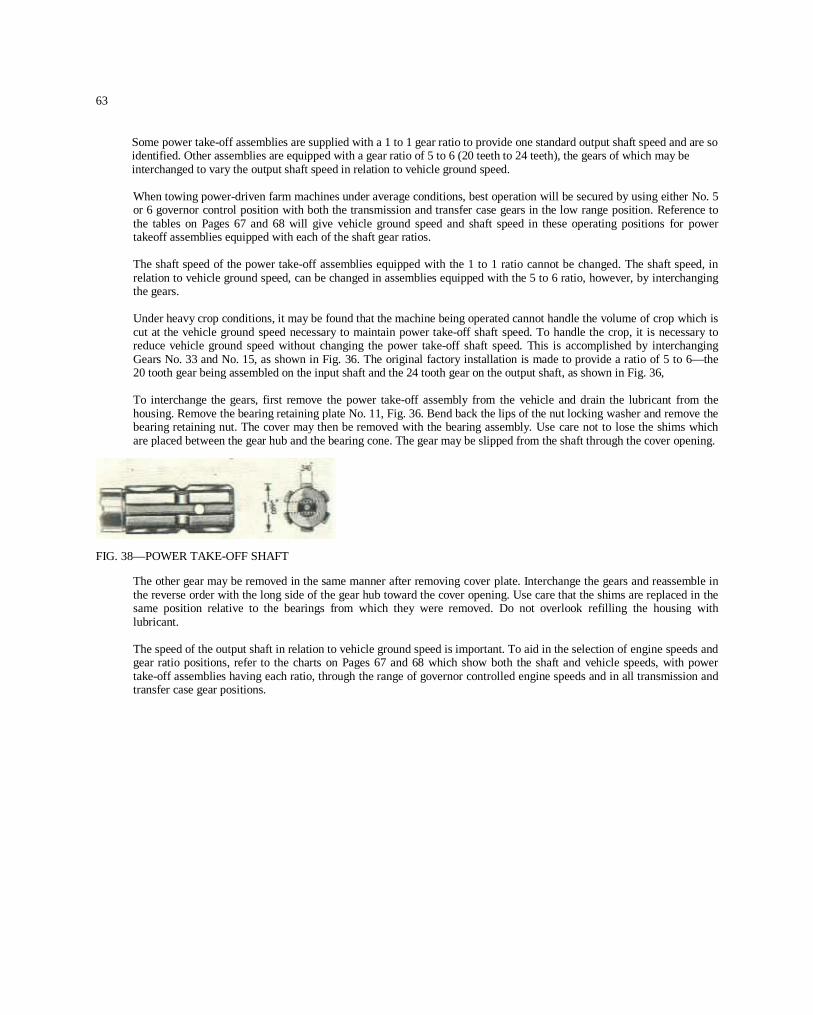
63
Some power take-off assemblies are supplied with a 1 to 1 gear ratio to provide one standard output shaft speed and are soidentified. Other assemblies are equipped with a gear ratio of 5 to 6 (20 teeth to 24 teeth), the gears of which may beinterchanged to vary the output shaft speed in relation to vehicle ground speed.
When towing power-driven farm machines under average conditions, best operation will be secured by using either No. 5or 6 governor control position with both the transmission and transfer case gears in the low range position. Reference tothe tables on Pages 67 and 68 will give vehicle ground speed and shaft speed in these operating positions for powertakeoff assemblies equipped with each of the shaft gear ratios.
The shaft speed of the power take-off assemblies equipped with the 1 to 1 ratio cannot be changed. The shaft speed, inrelation to vehicle ground speed, can be changed in assemblies equipped with the 5 to 6 ratio, however, by interchangingthe gears.
Under heavy crop conditions, it may be found that the machine being operated cannot handle the volume of crop which iscut at the vehicle ground speed necessary to maintain power take-off shaft speed. To handle the crop, it is necessary toreduce vehicle ground speed without changing the power take-off shaft speed. This is accomplished by interchangingGears No. 33 and No. 15, as shown in Fig. 36. The original factory installation is made to provide a ratio of 5 to 6—the20 tooth gear being assembled on the input shaft and the 24 tooth gear on the output shaft, as shown in Fig. 36,
To interchange the gears, first remove the power take-off assembly from the vehicle and drain the lubricant from thehousing. Remove the bearing retaining plate No. 11, Fig. 36. Bend back the lips of the nut locking washer and remove thebearing retaining nut. The cover may then be removed with the bearing assembly. Use care not to lose the shims whichare placed between the gear hub and the bearing cone. The gear may be slipped from the shaft through the cover opening.
FIG. 38—POWER TAKE-OFF SHAFT
The other gear may be removed in the same manner after removing cover plate. Interchange the gears and reassemble inthe reverse order with the long side of the gear hub toward the cover opening. Use care that the shims are replaced in thesame position relative to the bearings from which they were removed. Do not overlook refilling the housing withlubricant.
The speed of the output shaft in relation to vehicle ground speed is important. To aid in the selection of engine speeds andgear ratio positions, refer to the charts on Pages 67 and 68 which show both the shaft and vehicle speeds, with powertake-off assemblies having each ratio, through the range of governor controlled engine speeds and in all transmission andtransfer case gear positions.
PDF created with pdfFactory trial version www.pdffactory.com

64
CAUTION: When the vehicle is reversed, the power take-off shaft drive will turn in the reverse direction. Some farm machineswill be damaged if reverse driven. When operating trailed equipment, be sure to disengage the power take-off with the shiftlever before reversing the vehicle. Being able to reverse some power driven machines is an advantage to aid in freeing themachine should it become clogged in operation.
Inspect the power take-off unit periodically and add sufficient lubricant to keep it at filler plug level. Keep the attaching screwstight at all times and the breather or vent free of dirt.
When using the shaft drive, always install the shield which is provided for the safety of the operator.
PULLEY DRIVE ASSEMBLY.
The pulley drive assembly, with 8”(203 mm.) pulley, is driven through the power take-off shaft. It is held in position with fourcap screws and can be quickly removed or installed. Always remove this assembly when it is not in use to avoid damagethrough accident. For pulley speed data see Page 70.
When operating the pulley drive assembly use care that the vehicle is correctly aligned so the belt runs at the center of thepulley. Do not tighten the belt excessively: when too tight, rapid wear of the drive parts of both the machine being driven andpulley drive assembly may occur. If correctly adjusted the hand brake will hold the vehicle when ample drive tension is placedon the belt.
The belt pulley drive is operated from the transmission main shaft, giving the same power and speed ratios that are provided bythe transmission for the vehicle on the highway. To operate the pulley, with the vehicle standing, place the auxiliary (righthand) transfer case shift lever in the neutral position, designated as “N” in Fig. 3.
The nine governor controlled engine speeds in conjunction with the transmission gear shift positions provide a large selectionof pulley speeds. Select the governor and transmission gear shift positions that will provide the recommended speed of themachine being driven. Machines driven below this speed will seldom do a satisfactory job while speeds above normal willcause rapid wear and are, in some cases, dangerous. The table on Page 70 is provided as a guide in selecting the correct controlposition to secure the recommended speed.
CAUTION: When the belt drive is used, ground the vehicle with a bar or piece of chain so static electricity is dissipated orsparks might cause a fire in dusty or inflammable surroundings.
Keep the housing filled with lubricant to the level of the filler plug. (See “Lubrication Chart”.)
PDF created with pdfFactory trial version www.pdffactory.com

65
FIG. 39 CAPSTAN WINCH
1—Cover Plate Gasket 12—Filler Plug2—Gear Box 13— Worm Shaft Oil Seal3—Capstan Shaft Grease Fitting 14—Worm Shaft Needle Bearing4 —Capstan Shaft Thrust Washer 15—Worm and Gear Set5—Capstan Shaft Retaining Washer 1 6—Worm Shaft Ball Bearing6—Capstan Shaft Screw Lockwasher 17— Bearing Retainer Cap Gasket7—-Capstan Shaft Screw 18 —Bearing Retainer Cap8—Cover Screw 19—Gear Box Cover Plate Screw Lockwasher9 —Cover Screw Lockwasher 20— Gear Box Cover Plate Screw10 —Capstan Shaft Bushing (Upper) 21—Cover Plate11—Capstan Shaft Bushing (Lower) 22 —Drain Plug
CAPSTAN WINCH.The capstan winch is designed for 5000 lb. (2268 Kg.) pull, using either 3/4" (19 mm.) or 1” (25 mm.) manila rope. The wormgears have a ratio of 75 to 1 which provides a rope speed of 19 feet per minute (5.8 m./min.) with an engine speed of 1200rpm. A shift lever is mounted on the assembly for engagement control. Engage the drive with the engine idling only andwithout load; limit the engine speed to 1200 rpm.Lubrication is important because the parts must withstand high pressures when operating at maximum pull. Filler and drainplugs are provided in the gear housing with an oil level stick on the filler plug. The oil capacity is one quart of SAE 90 gear oilin Summer and SAE 80 in Winter. Change the oil twice each year—in Fall and Spring.Hydraulic fitting No. 3, Fig. 39, indicated by the arrow cast on the gear box, is provided to lubricate the capstan spindle. Tolubricate, align the opening in the capstan with arrow. Use chassis lubricant to lubricate the spindle, also lubricate the roperoller at each end and the shift rail and the drive shaft bushing in the winch drive support bracket mounted on the front of theengine. Use an oil can to lubricate the winch drive universal joints.A cotter pin is used to pin the winch drive shaft to the universal joint at the engine end and acts as a shear pin to preventoverloading. Should this pin shear off, be sure to replace it with a cotter pin of the same size. Do not replace it with a solid pinor drill the hole oversize for a larger pin.
PDF created with pdfFactory trial version www.pdffactory.com

66
Draw Bar PullThe power plant of the Universal Jeep is particularly well adapted to the great variety of applications of the Jeep.For higher speed highway use, and draw bar pull requirements for towing loads, the full engine power is available;for power take-off shaft and pulley drive, the full engine torque (turning effort) is available.
Draw bar pull is the force exerted by a vehicle to tow a trailed load and is expressed in pounds.
For continuous agricultural work, the maximum draw bar pull should be limited to 1200 pounds (544 Kg.). TheUniversal Jeep is capable of much higher draw bar pulls than the 1200 pounds (544 Kg.) approved for continuousservice, which may be used for starting loads or towing loads for short periods on good ground in which case adraw bar pull as high as 1800 pounds (817 Kg.) may be safely used.
Maximum continuous draw bar pulls are most often encountered in plowing, disking and harrowing and it is inthese applications that the owner should guard against continuously exceeding the recommended limit.
The approved limit of 1200 pounds (544 Kg.) may be judged by the following operations which nearly approachthis limit:
Operating two 12 inch (30.5 cm.) plows at a depth of 6’2 inches (16.5 cm.) in dry clay loam.
Operating a 7 foot (2.13 meter) tandem disk at a depth of 412 inches (11.4 cm.) in hard winter packed soil.
Operating a 3-section spring tooth harrow at a depth of 5 inches (12.7 cm.) in soil which has been previouslydisked.
It is expected that, either on account of soil conditions or implement adjustments, these draw bar pulls will beexceeded. In these instances, tire slippage provides an inherent safeguard against overloading. Do not add weight,other than the standard bumper weight, Page 61, to equalize traction on all four wheels to increase draw bar pull.
Full information is given in the charts on Page 70 of horsepower at the drawbar and also, at the power take-offsplined shaft under various operating conditions.
PDF created with pdfFactory trial version www.pdffactory.com

67
POWER TAKE-OFF SHAFT AND VEHICLE GROUND SPEEDSALL GEAR SHIFT POSITIONS
MILES PER HOURPOWER TAKE-OFF 5 TO 6 GEAR RATIO
Transmission Gear In Engine
Low Intermediate High SpeedTake-Off Vehicle Take-Off Vehicle Take-Off Vehicle
Shaft Speed Shaft Speed Shaft SpeedR.P.M. M.P.H. R.P.M. M.P.H. R.P.M. M.P.H.
298 2.22 537 4.01 833 6.221 298 5.40 637 9.75 833 15.13 1000
357 2.67 644 4.81 1000 7.472 357 6.48 644 11.71 1000 18.15 1200
417 3.11 752 5.62 1166 8.723 417 7.56 752 13.66 1166 21.17 1400
476 3.56 859 6.42 1333 9.964 476 8.65 859 15.61 1333 24.20 1600
536 4.00 967 7.22 1500 12.085 536 9.73 967 17.56 1500 27.22 1800
595 4.44 1074 8.02 1666 12.456 595 10.81 1074 19.51 1666 30.28 2000
655 4.89 1182 8.83 1833 13.707 655 11.89 1182 21.46 1833 33.27 2200
714 5.34 1289 9.63 2000 14.948 714 12.97 1289 23.41 2000 36.31 2400
774 5.78 1396 10.43 2166 16.199 774 14.05 1396 25.36 2166 39.33 2600
POWER TAKE-OFF 6 TO 5 GEAR RATIOTransmission Gear In Engine
Governor TransferControl In Low Intermediate High SpeedPosition ________
Take-Off Vehicle Take-Off Vehicle Take-Off Vehicle Shaft Speed Shaft Speed Shaft SpeedR.P.M. M.P.H. R.P.M. M.P.H. R.P.M. M.P.H.
Low 428 2.22 773 4.01 1200 6.221 High 428 5.40 773 9.75 1200 15.13 1000
Low 614 2.67 928 4.81 1440 7.472 High 514 6.48 928 11.71 1440 18.15 1200
Low 600 3.11 1083 5.62 1680 8.723 HIgh 600 7.58 1083 13.66 1680 21.17 1400
Low 685 3.56 1237 8.42 1920 9.964 High 685 8.65 1237 16.61 1920 24.20 1600
Low 771 4.00 1392 7.22 2180 12.085 High 771 9.73 1392 17.56 2160 27.22 1800
Law 857 4.44 1547 8.02 2400 12.456 High 857 10.81 1647 19.51 2400 30.25 2000
Low 942 4.89 1702 8.83 2640 13.707 High 942 11.89 1702 21.46 2640 33.27 2200
Low 1028 5.34 1856 9.63 2880 14.948 High 1028 12.97 1856 23.41 2880 36.31 2400
Low 1114 5.78 2011 10.43 3120 16.19 I9 High 1114 14.05 2011 25.36 3120 39.33 2600
PDF created with pdfFactory trial version www.pdffactory.com

68
POWER TAKE-OFF SHAFT AND VEHICLE GROUND SPEEDSALL GEAR SHIFT POSITIONS
MILES PER HOURPOWER TAKE—OFF 1 TO 1GEAR RATIO
Transmission Gear InGovernor Transfer EngineControl In Low Intermediate High SpeedPosition
Take-Off Vehicle Take-Off Vehicle Take-Off VehicleShaft Speed Shaft Speed Shaft Speed
R.P.M. M.P.H. R.P.M. M.P.H. R.P.M. M.P.H.Low 358 2.22 644 4.01 1000 6.22High 358 6.40 644 9.76 1000 15.13 1000
Low 428 2.67 773 4.81 1200 7.472 High 428 6.48 773 11.71 1200 18.15 1200
Low 500 3.11 902 5.62 1400 8.723 High 500 7.56 902 13.66 1400 21.17 1400
Low 671 3.66 1031 6.42 1600 9.964 High 671 8.65 1031 15.61 1600 24.20 1600
Low 643 4.00 1160 7.22 1800 12.085 High 643 9.73 1160 17.56 1800 27.22 1800
Low 714 4.44 1289 8.02 2000 12.466 .High 714 10.81 1289 19.51 2000 30.25 2000
Low 786 4.89 1418 8.83 2200 13.707 High 786 11.89 1418 21.46 2200 33.27 2200
Low 857 5.34 1647 9.63 2400 14.948 High 857 12.97 1547 23.41 2400 36.31 2400
Low 929 5.78 1675 10.43 2600 16.199 High 929 14.05 1675 25.36 2600 39.33 2600
POWER TAKE-OFF SHAFT AND VEHICLE GROUND SPEEDSALL GEAR SHIFT POSITIONSKILOMETERS PER HOUR
POWER TAKE-OFF 5 TO 6 GEAR RATIOTransmission Gear In
Governor Transfer — ~— — EngineControl In Low Intermediate High SpeedPosition
Take-Off Vehicle Take-Off Vehicle Take-Off VehicleShaft Speed Shaft Speed Shaft Speed
R.P.M. K.P.M. R.P.M. K.P.M. R.P.M. K.P.M.Low 298 3.57 537 6.45 833 10.00
1 High 298 8.68 537 15.68 833 24.35 1000Low 357 4.29 644 7.73 1000 12.02
2 High 357 10.43 644 18.84 1000 29.20 1200Low 417 5.00 762 9.04 1166 14.02
3 High 417 12.16 752 21.98 1186 34.05 1400Low 476 5.72 859 10.33 1333 18.03
4 High 476 13.91 859 25.12 1333 38.93 1600Low 536 6.44 967 11.61 1500 19.43
5 High 536 15.65 967 28.25 1500 43.80 1800Low 595 7.15 1074 12.90 1666 20.00
6 High 595 17.39 1074 31.40 1666 48.65 2000Low 655 7.86 1182 14.20 1833 22.02
7 High 655 19.11 1182 34.53 1833 53.53 2200Low 714 8.59 1289 15.48 2000 24.03
8 High 714 20.87 1289 37.66 2000 58.40 2400Low 774 9.30 1396 16.78 2166 26.04
9 High 774 22.60 1396 40.80 2166 63.28 2600
PDF created with pdfFactory trial version www.pdffactory.com

69
POWER TAKE-OFF 6 TO 5 GEAR RATIO
Governor Transfer Transmission Gear In IControl In Low Intermediate High EnginePosition Speed
Take-Off Vehicle Take-Off Vehicle Take-Off VehicleShaft Speed Shaft Speed Shaft Speed
R.P.M. K.P.M. R.P.M. K.P.M. R.P.M. K.P.M.Low 428 3.57 773 645 1200 I 10.00
2435 lOGO9.04
10.33 1920 16.034 Higl 685 13.91 1237 25.12 1920 38.93 1600
Low 771 6.44 1392 11.61 2160 19.435 HI~I 771 15.65 1392 28.25 2160 43.80 1800
Low 857 7.15 1547 12.90 2400 20.006 HigI 857 17.39 1547 31.40 2400 48.65 2000
942 7.86 1702 14.20 2640 22027 igl 942 19.11 1702 34.53 2640 53.53 2200
1028 8.59 1856 15.48 2880 24.038 1028 20.87 1856 37.66 2880 50.40 2400
1114 9.30 2011 16.78 3120 26.049 1114 j 22.60 2011 40.80 3120 63.28 2600
POWER TAKE-OFF GEAR RATIO-__ POWER TAKE-OFF TO1 GEAR RATIO
Transmission Gear InGovernor Transfer ______——--—— —-~-—--—--———-—— — EngineControl In Low Intermediate High SpeedPosition _______ — __________ _________
Take-Off Vehicle Take-Off Vehicle Take-Off Vehicle Shaft Speed Shaft Speed Shaft SpeedR.P.M. K.P.M. R.P.M. K.P.M. R.P.M. K.P.M.
Low 358 3.57 644 6.45 1000 10.001 High 358 8.88 844 15.68 1000 24.35 1000
Low 428 4.29 773 7.73 1200 12.022 High 428 10.43 773 18.84 1200 29.20 1200
Low 500 5.00 902 9.04 1400 14.023 High 500 12.16 902 21.98 1400 34.05 1400
Low 571 5.72 1031 10.33 1600 16.034 High 571 13.91 1031 25.12 1600 38.93 1600
Low 643 L44 1160 11.61 1800 19.435 High 843 15.85 1160 28.25 1800 43.80 1800
Low 714 7.15 1289 12.90 2000 20.006 High 714 17.39 1289 31.40 2000 48.65 2000
Low 786 7.86 1418 14.20 2200 22.027 High 786 19.11 1418 34.53 2200 53.53 2200
Low 857 8.59 1547 15.48 2400 24.038 High 857 20.87 1647 37.68 2400 58.40 2400
Low 929 9.30 1675 16.78 2800 26.04P High 929 22.60 1875 40.80 2600 63.28 2600
PDF created with pdfFactory trial version www.pdffactory.com

70
Pulley Speeds (R.P.M.) - 8” (20. 3CM.) PulleyPower Take-Off Gear Ratios
Governor 6-6 RATIO 6-5 RATIO 1-1 RATIOControl TRANSMISSION TRANSMISSION TRANSMISSION EnginePositions Sp~eds
Low Hh Inter High Low Inter. HighInter. ‘6
— Low ~. -
1 255 460 I 714 367 663 1028 306 552 857 1000
2 306 552 857 440 795 1234 367 662 1028 1200
3 357 645 1000 514 928 1440 428 - 774 1200 1400
4 ~ - 737 1143 587 1061 1645 490 884 1372 1600
5 459 829 1285 660 1193 1851 551 995 1542 1800
6 510 921 1428 734 1326 2057 j612 1105 1714 2000
7 561 1031 1571 807 1458 2262 673 1237 1885 2200
8 612 1105 1114 881 1591 2468 734 1326 2057 2400
9 663 1197 1851 954 1723 2674 796 1436 2228 2600
SPLINE SHAFT HORSEPOWER.The chart below shows the draw bar horsepower at the governor controlled engine speeds and the horsepower at the splineshaft with~ the vehicle stationary. Also is shown the horsepower available at the spline shaft with the vehicle at the maximumapproved weight (3500 lbs.) (1590 Kg.) moving at the speed shown and exerting a draw bar pull of zero pounds through 1200pounds (544 Kg.) (maximum recommended) in steps of 300 pounds (136 Kg.).
H.P. at P.T.O. Spline ShaftGoverned Vehicle 3500 Lb. Vehicle Moving withEngine Speed Draw Bar Vehicle _____—R.P.M. M.P.H.* H.P.*~ Stationary No Lbs. 300 Lbs. 600 Lbs. 700 Lbs. 1200 Lbs.
Draw Bar Draw Bar Draw Bar Draw Bar Draw BarPull Pull Pull Pull Pull
1000 2.2 7.18 15.4 12.8 11.0 9.3 7.5 5.71200 2.7 8.62 18.3 16.2 14.0 12.0 9.8 7.81400 3.1 10.06 23.3 19.6 17.1 14.7 12.1 9.61600 3.6 11.49 27.1 22.9 20.1 17.4 14.4 11.51800 4.0 12.93 30.9 26.3 23.0 19.9 16.7 13.52000 4.5 14.38 33.0 29.1 25.6 21.9 18.4 14.82200 4.9 15.80 33.0 31.7 27.8 23.8 20.0 16.02400 5.4 17.24 33.11 33.0 29.7 25.5 21.1 16.92600 5.8 18.68 33.0 33.0 31.4 26.7 I 22.1 17.5
*Vehicle speed in low transmission and transfer case ratios.**Based on maximum recommended draw bar pull for cantinuouu servnce-—1200 Lbs.
METRICMetric H.P. at P.T.O. Spline Shaft
Governed Vehicle Draw Bar 1590 Kg. Vehicle Moving withEngine Speed H.P.~’ Vehicle 135 Kg. 270 Kg. 405 Kg. 540 Kg.R.P.M. K.P.H.~ (Metric) Stationary DrawLr Draw Bar Draw Bar Draw Bar Draw Bar
Pull Pull Pull Pull Pall1000 3.5 7.28 15.6 13.0 11.2 9.4 7.6 5.81200 4.4 8.74 19.6 16.4 14.2 12.2 9.9 7.71400 5.0 10.20 23.6 19.9 17.3 14.9 12.3 9.71600 5.8 11.65 27.5 23.2 20.4 17.6 14.6 11.71800 6.4 13.11 31.3 26.7 23.3 20.2 16.9 13.72000 7.2 14.58 33.6 29.5 25.9 22.2 18.7 15.02200 7.9 16.02 33.5 32.1 28.2 24.1 20.3 16.22400 8.7 17.48 33.5 33.5 30.1 25.9 21.4 17.12800 9.3 18.94 33.5 33.6 31.8 27.1 22.4 17.7
~Vehicle speed in low transmission and transfer case ratios.1’Based on maximum recommended draw bar mull for continuous service 640 Kg.
PDF created with pdfFactory trial version www.pdffactory.com

71
Directions For Ordering PartsWhen new parts are necessary, it is recommended that these be ordered from the nearest Willys-Overland Dealer.
Do not order parts in a letter in which some other subject is treated.
When ordering parts for a particular vehicle, give the model, engine and serial number of the vehicle.
The serial number will be found stamped on a plate located on the right side of the dash under the hood.
Engine number will be found stamped on top the water pump boss at the front end of the cylinder block.
Never order in sets, but give the exact quantity of the parts desired.
Specify both the part number and the name of part in full, and if similar parts are used on both the right and left-hand sides,specify for which side you want the new part or parts, because many parts made for right and left sides are notinterchangeable.
If in doubt as to the parts needed, take the broken parts to your dealer. Write your name and address plainly on the package,so that it can be identified when received.
Write, stating what you are sending and the purpose for which it is sent regardless of any previous correspondence. Allparts are held until advice is received.
Give definite shipping instructions whether the new parts are to be sent by express, freight or parcel post.
NOTE: Parts replaced under the terms of the Warranty (Page 4) must be left with the Willys-Overland Dealer who makesthe replacement, if full credit is expected.
This is important for owners to know when traveling outside the territory in which their vehicle was originally purchased,particularly when credit for old parts cannot be established to satisfaction of the Dealer.
In this connection, a forwarding address should be given by the owner in order to insure the receipt of proper credit.
ACCEPT ONLY GENUINE FACTORY PARTS
PDF created with pdfFactory trial version www.pdffactory.com

Alphabetical IndexAiming Headlamps 34Air Cleaner 17Anti-Freeze Solution 53Axle—Front 41Axle Lubrication 18Axle—Rear 44Battery 33Belt—Fan 31Brakes 44Brake—Hand 46Bumper Weight 61Cap—Radiator Filler 31Capstan Winch 65Carburetor 28Carburetor Throttle Bell Crank 59Chassis Lubrication 16Cleaner—Air 17Clutch 35Cold Weather Precautions 53Controls and Switches 8Cooling System 30Data. General 5Differential Lubrication 18Diffuser—Fuel 29Distributor 27Distributor Lubrication 17Draw Bar Pull 66Electrical System 33Emergency Chart 54Engine Lubrication 16Engine Mountings 23Engine Tune-up 19Extra Equipment 56Fan Belt 31Filter—Oil 17Foot Brakes 44Four Wheel Drive Use 13Front Axle 41Fuel Diffuser 29Fuel Gauge 33Fuel Pump 29Fuel System 28Fuel Tank 30Gauge—Fuel 33Generator 26General Data 5General Lubrication 15Governor—King Seeley 58Governor Lubrication 18Governor—Monarch 59Governor—Novi 56Hand Brake 46Headlamp Aiming 34Heat Control—Manifold 23Heat Indicator 31Horsepower 5Horsepower at Spline Shaft 70Ignition Distributor 27Ignition Distributor Lubrication 17Ignition Timing 21Inspection 6Lamp Bulbs 5Lighting System 34
Light Switch 34Lubrication 15Lubrication Chart 36Lubrication Specifications 15Main Light Switch 34Maintenance of Vehicle 19Manifold Heat Control 23Oil Filter 17Oil Pump 24Operation of Vehicle 8Power Take-off 61Power Take-off Lubrication 18Power Take-off Splined Shaft 62Propeller Shaft 41Propeller Shaft—Power Take-off 62Pulley Drive Assembly 64Radiator 30Rear Axle 44Serial Number Location 5Shackles 51Shaft—Propeller 41Shock Absorbers 52Spark Plugs 27Specifications—Lubrication 15Speedometer Drive Lubrication 17Speeds—Power Take-off 67Springs 51Starting Motor 27Starting Motor Lubrication 17Steering Gear Lubrication 17Steering Knuckle 42Steering System 48Stoplight Switch 34Switches and Controls 8Switch—Main Light 34Switch—Stoplight 34Thermostat 31Throttle Bell Crank—Carburetor 59Timing Ignition 21Timing Valves 20Tires 51Transfer Case 39Transfer Case Gear Shift 13Transfer Case Lubrication 18Transmission 38Transmission Lubrication 18Tuning Engine 19Universal Joint Lubrication 18Valve Timing 20Vehicles Operation 8Voltage Regulator 26Warranty 4Water Pump 31Weights 5Weight—Bumper 61Wheels 51Wheelbase 5Wheel Bearings—Front 49Wheel Bearing Lubrication 18Wheel Bearings—Rear 50Winch—Capstan 65Wiring Diagram 32
PRINTED BY THE CALVERT-HATCH COMPANY, CLEVELAND. OHIO. U. S. A.
DEC. 10. 1948
PDF created with pdfFactory trial version www.pdffactory.com
