williamsport, pa 17701 u.s.a. service bulletin€¦ · · 2008-06-29service bulletin no. 342e...
TRANSCRIPT

652 Oliver Street Williamsport, PA 17701 U.S.A.
Tel. 570-323-6181 Fax. 570-327-7101 www.lycoming.textron.com DATE: May 18, 2004 Service Bulletin No. 342E
(Supersedes Service Bulletin No. 342D) Engineering Aspects are
FAA Approved SUBJECT: Fuel Line (Stainless Steel Tube Assy.) and Support Clamp Inspection and
Installation
MODELS AFFECTED: All fuel injected Lycoming engines indicated in fuel line and clamping diagrams.
TIME OF COMPLIANCE: Check every 100 hours, annual inspection, overhaul and any time fuel lines or clamps are serviced, removed or replaced.
There have been instances of fuel line breakages where support clamps have been omitted during field overhaul or repair. The support clamps dampen line vibration due to the impact of cooling air and vibration from the engine and/or aircraft. Also, the fuel supply lines between the fuel injector manifold and the nozzles can become damaged and leak if they are severely bent or kinked during engine maintenance.
As a means of minimizing the hazards of fuel line damage, the following inspection of fuel lines and clamps is required. 1. The fuel lines to the nozzles are made from 1/8 inch tubing. A separate line supplies fuel to the intake port of
each cylinder. Check each line visually for any evidence of physical damage and for stains caused by fuel leakage.
2. Remove any line that appears faulty. Do not attempt to repair any line that leaks. Bent lines may be straightened; however, any line with an inside radius less than 5/8 inch must be replaced. Do not reuse any line that is dented; cracks can develop at the site of a dent. Also inspect solder joints at end of lines for cracks. Replace cracked lines, they cannot be repaired. See the latest edition of Service Instruction No. 1301 for superseded fuel line identification, bending requirements (see Figure 1) and replacement information.
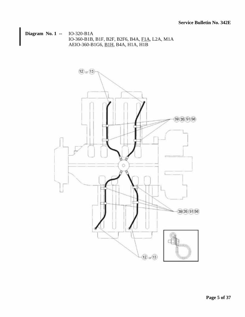
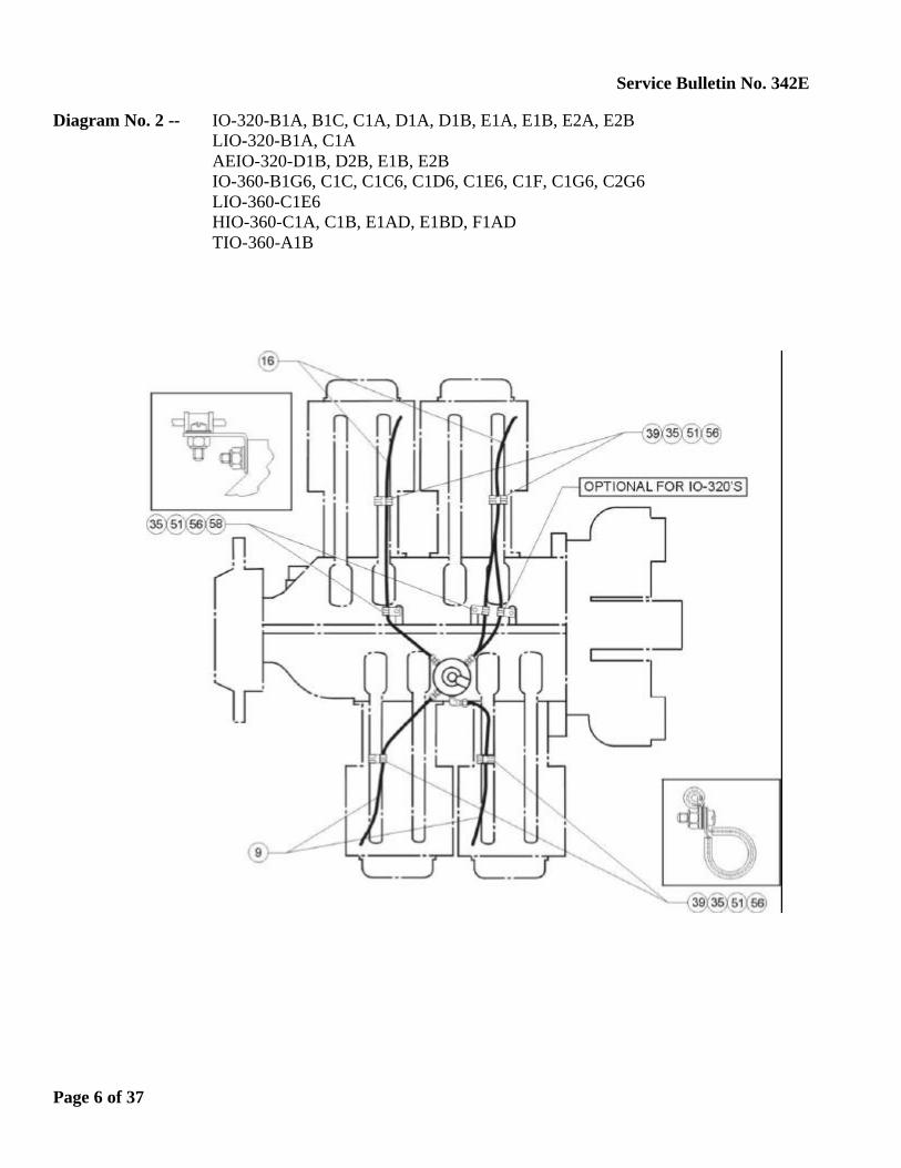
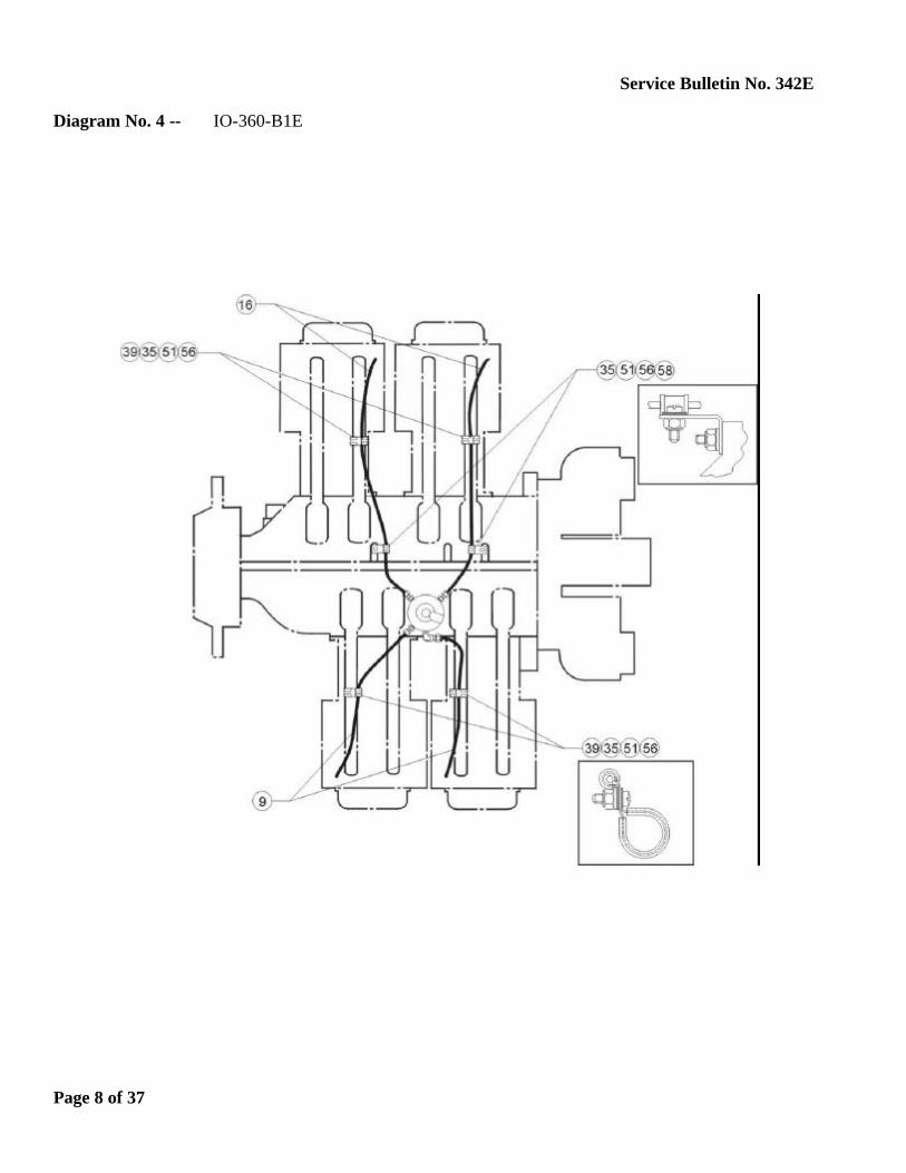
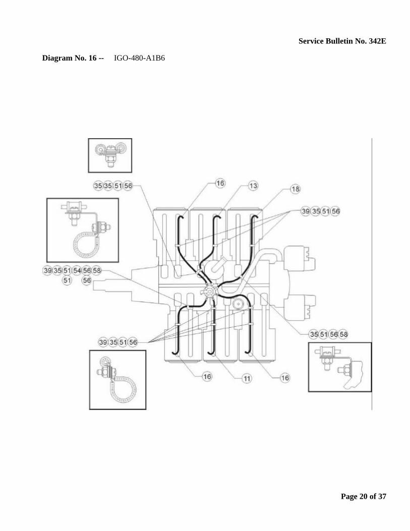
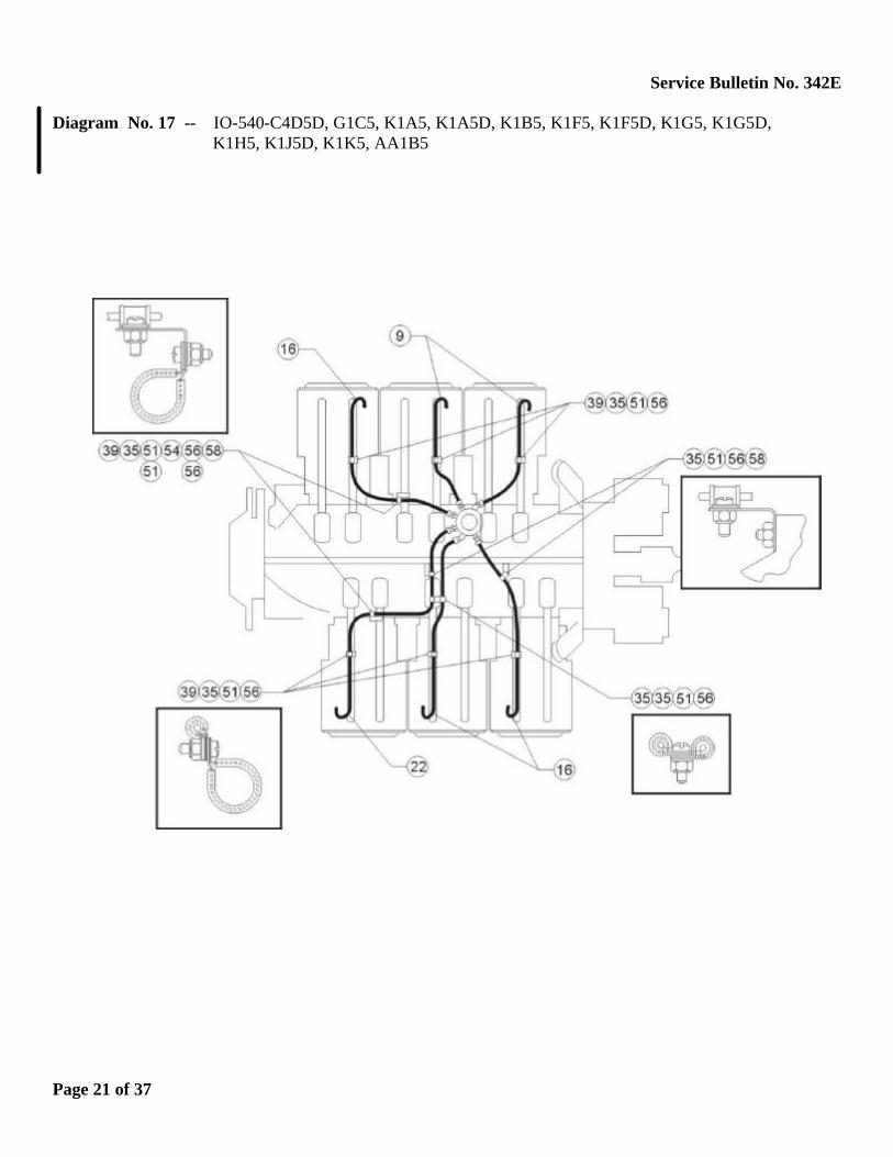
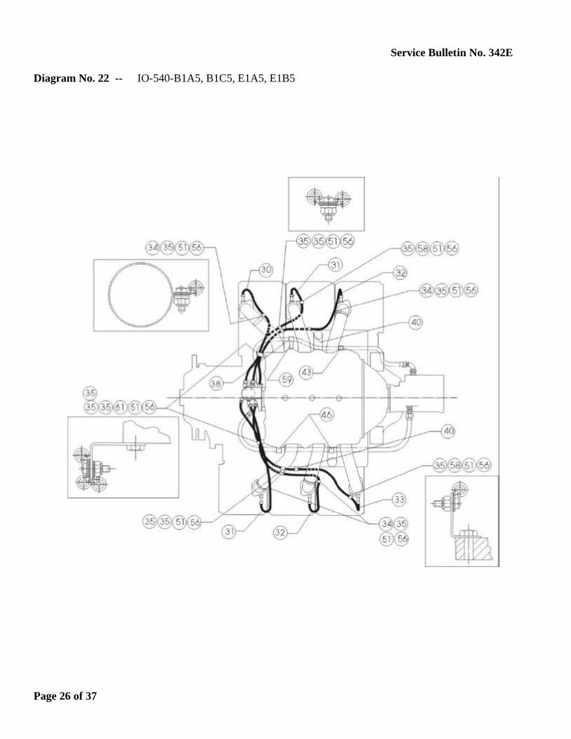
3. Examine the location of the clamps that secure the lines to the engine and compare them with the diagrams shown in this bulletin. If clamps are missing, replace fuel line and install clamps as indicated. Also, examine the lines to ensure the clamps securely support the line and for signs of chafing. Replace fuel lines that show indications of chafing and/or have loose clamps.
4. Older engines that used metal clamps with no cushion must use the P/N LW-12598 fuel line sleeve at each of those clamping locations. The fuel line sleeve is not used with the cushioned clamps. Any cushioned clamp, where the cushion has deteriorated or is missing, must be replaced with a new cushion clamp.
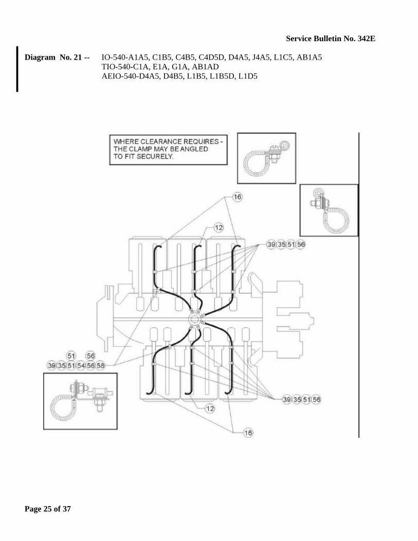
5. Compliance with the bulletin must be noted in the aircraft log book. NOTE: If difficulty is experienced when installing clips on a cylinder fuel injector line due to aircraft baffling, the clips may be installed in positions that provide clearance. Do not permit fuel lines to contact engine
or airframe baffle hardware; maintain minimum clearance of 3/16 inch between line and any engine or airframe surface.
NOTE: Revision “E” adds new models indicated by underline and change bar; illustration changes indicated by arrows and change bars; and adds five new diagrams 10A (HIO-360-G1A), 18A (IO-540-AE1A5), 19A (IO-540-AB1A5 & TIO-540-AK1A), 21A (IO-540-N1A5, -R1A5, -V4A5, -V4A5D, -W1A5, -W1A5D, -W3A5D) and 24A (IO-540-M1C5). © 2004 by Lycoming, “All Rights Reserved” Page 1 of 37
MANDATORYSERVICE BULLETIN

Service Bulletin No. 342E INDEX
(Fuel Lines, Clamps, Brackets, Attaching Hardware as shown in the following Engine Diagrams)
1 76356 TUBE ASSY., Manifold to nozzle fuel line2 76357 TUBE ASSY., Manifold to nozzle fuel line3 76358 TUBE ASSY., Manifold to nozzle fuel line4 76359 TUBE ASSY., Manifold to nozzle fuel line5 76360 TUBE ASSY., Manifold to nozzle fuel line6 76361 TUBE ASSY., Manifold to nozzle fuel line7 76362 TUBE ASSY., Manifold to nozzle fuel line8 LW-12098-0-100 TUBE ASSY., Manifold to nozzle fuel line9 LW-12098-0-140 TUBE ASSY., Manifold to nozzle fuel line
10 LW-12098-0-150 TUBE ASSY., Manifold to nozzle fuel line11 LW-12098-0-160 TUBE ASSY., Manifold to nozzle fuel line12 LW-12098-0-170 TUBE ASSY., Manifold to nozzle fuel line13 LW-12098-0-180 TUBE ASSY., Manifold to nozzle fuel line14 LW-12098-0-190 TUBE ASSY., Manifold to nozzle fuel line15 LW-12098-0-200 TUBE ASSY., Manifold to nozzle fuel line16 LW-12098-0-210 TUBE ASSY., Manifold to nozzle fuel line17 LW-12098-0-220 TUBE ASSY., Manifold to nozzle fuel line18 LW-12098-0-230 TUBE ASSY., Manifold to nozzle fuel line19 LW-12098-0-240 TUBE ASSY., Manifold to nozzle fuel line20 LW-12098-0-260 TUBE ASSY., Manifold to nozzle fuel line21 LW-12098-0-270 TUBE ASSY., Manifold to nozzle fuel line22 LW-12098-0-280 TUBE ASSY., Manifold to nozzle fuel line23 LW-12098-0-300 TUBE ASSY., Manifold to nozzle fuel line24 LW-12098-0-310 TUBE ASSY., Manifold to nozzle fuel line25 LW-12098-0-320 TUBE ASSY., Manifold to nozzle fuel line26 LW-12098-0-340 TUBE ASSY., Manifold to nozzle fuel line27 LW-12098-0-350 TUBE ASSY., Manifold to nozzle fuel line28 LW-12098-0-390 TUBE ASSY., Manifold to nozzle fuel line29 LW-12098-0-412 TUBE ASSY., Manifold to nozzle fuel line30 LW-13995-0-202 TUBE ASSY., Manifold to nozzle fuel line31 LW-13995-0-224 TUBE ASSY., Manifold to nozzle fuel line32 LW-13995-0-271 TUBE ASSY., Manifold to nozzle fuel line33 LW-13995-0-284 TUBE ASSY., Manifold to nozzle fuel line34 AN735-26 CLAMP35 LW-16266-10-13* CLAMP36 LW-16266-10-25* CLAMP37 LW-16266-10-38* CLAMP38 LW-16266-10-44* CLAMP39 LW-16266-10-75* CLAMP40 LW-16266-25-13* CLAMP41 LW-16266-25-25* CLAMP42 LW-16266-25-38* CLAMP43 LW-16266-25-44* CLAMP
Page 2 of 37
Service Bulletin No. 342E
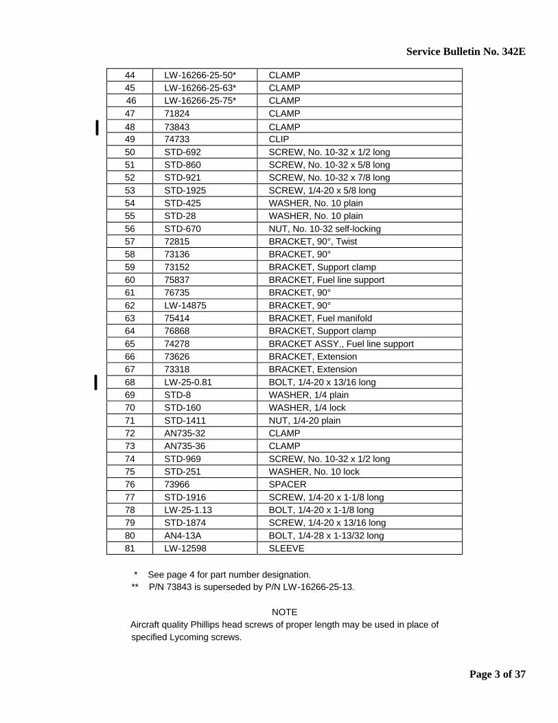
44 LW-16266-25-50* CLAMP 45 LW-16266-25-63* CLAMP 46 LW-16266-25-75* CLAMP 47 71824 CLAMP 48 73843 CLAMP 49 74733 CLIP 50 STD-692 SCREW, No. 10-32 x 1/2 long 51 STD-860 SCREW, No. 10-32 x 5/8 long 52 STD-921 SCREW, No. 10-32 x 7/8 long 53 STD-1925 SCREW, 1/4-20 x 5/8 long 54 STD-425 WASHER, No. 10 plain 55 STD-28 WASHER, No. 10 plain 56 STD-670 NUT, No. 10-32 self-locking 57 72815 BRACKET, 90°, Twist 58 73136 BRACKET, 90° 59 73152 BRACKET, Support clamp 60 75837 BRACKET, Fuel line support 61 76735 BRACKET, 90° 62 LW-14875 BRACKET, 90° 63 75414 BRACKET, Fuel manifold 64 76868 BRACKET, Support clamp 65 74278 BRACKET ASSY., Fuel line support 66 73626 BRACKET, Extension 67 73318 BRACKET, Extension 68 LW-25-0.81 BOLT, 1/4-20 x 13/16 long 69 STD-8 WASHER, 1/4 plain 70 STD-160 WASHER, 1/4 lock 71 STD-1411 NUT, 1/4-20 plain 72 AN735-32 CLAMP 73 AN735-36 CLAMP 74 STD-969 SCREW, No. 10-32 x 1/2 long 75 STD-251 WASHER, No. 10 lock 76 73966 SPACER 77 STD-1916 SCREW, 1/4-20 x 1-1/8 long 78 LW-25-1.13 BOLT, 1/4-20 x 1-1/8 long 79 STD-1874 SCREW, 1/4-20 x 13/16 long 80 AN4-13A BOLT, 1/4-28 x 1-13/32 long 81 LW-12598 SLEEVE * See page 4 for part number designation. ** P/N 73843 is superseded by P/N LW-16266-25-13.
NOTE Aircraft quality Phillips head screws of proper length may be used in place of
specified Lycoming screws.
Page 3 of 37

Service Bulletin No. 342E
Page 4 of 37
PLEASE Note … When installing clamps, it does not matter whether the clamp is installed to the right or left of the shroud tube, only that it is clamped at that location and there is 3/16 inch clearance between the line and any engine or airframe surface.
Service Bulletin No. 342E
Diagram No. 1 -- IO-320-B1A IO-360-B1B, B1F, B2F, B2F6, B4A, F1A, L2A, M1A AEIO-360-B1G6, B1H, B4A, H1A, H1B
Page 5 of 37
Service Bulletin No. 342E
Diagram No. 2 -- IO-320-B1A, B1C, C1A, D1A, D1B, E1A, E1B, E2A, E2B LIO-320-B1A, C1A AEIO-320-D1B, D2B, E1B, E2B IO-360-B1G6, C1C, C1C6, C1D6, C1E6, C1F, C1G6, C2G6 LIO-360-C1E6 HIO-360-C1A, C1B, E1AD, E1BD, F1AD TIO-360-A1B
Page 6 of 37

Service Bulletin No. 342E
Diagram No. 3 -- IO-360-A1A, A1B, A1B6, A1B6D, A1C, A1D, A1D6, A2A, A2B, A3B6, A3B6D, B1D, B1F, B2F, C1A, C1B, C1D6, J1A6D, M1B HIO-360-C1A, C1B AEIO-360-A1A, A1B, A1B6, A1D, A1E, A1E6, B1F, B2F
Page 7 of 37
Service Bulletin No. 342E
Diagram No. 4 -- IO-360-B1E
Page 8 of 37
Service Bulletin No. 342E
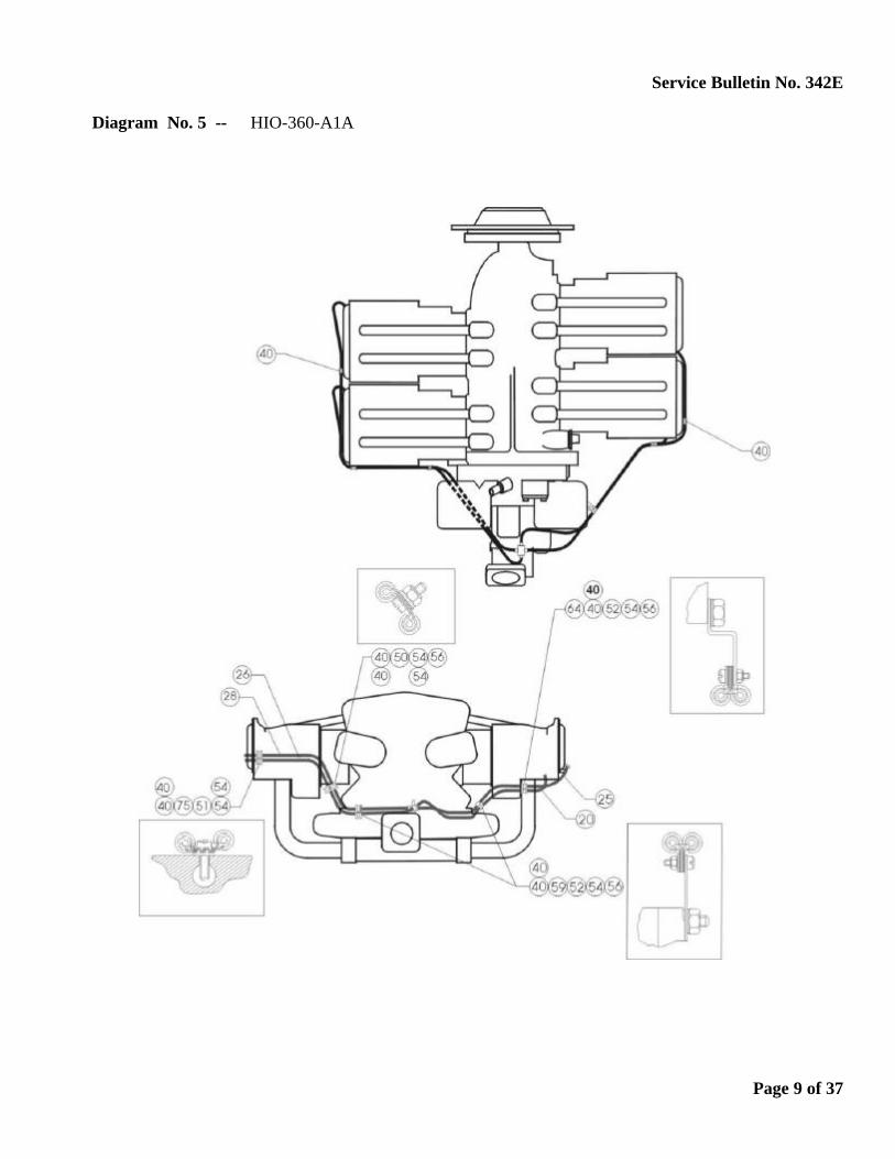
Diagram No. 5 -- HIO-360-A1A
Page 9 of 37
Service Bulletin No. 342E
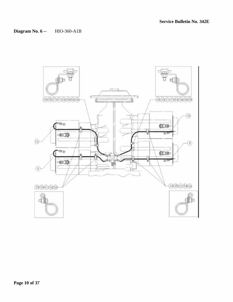
Diagram No. 6 -- HIO-360-A1B
Page 10 of 37
Service Bulletin No. 342E
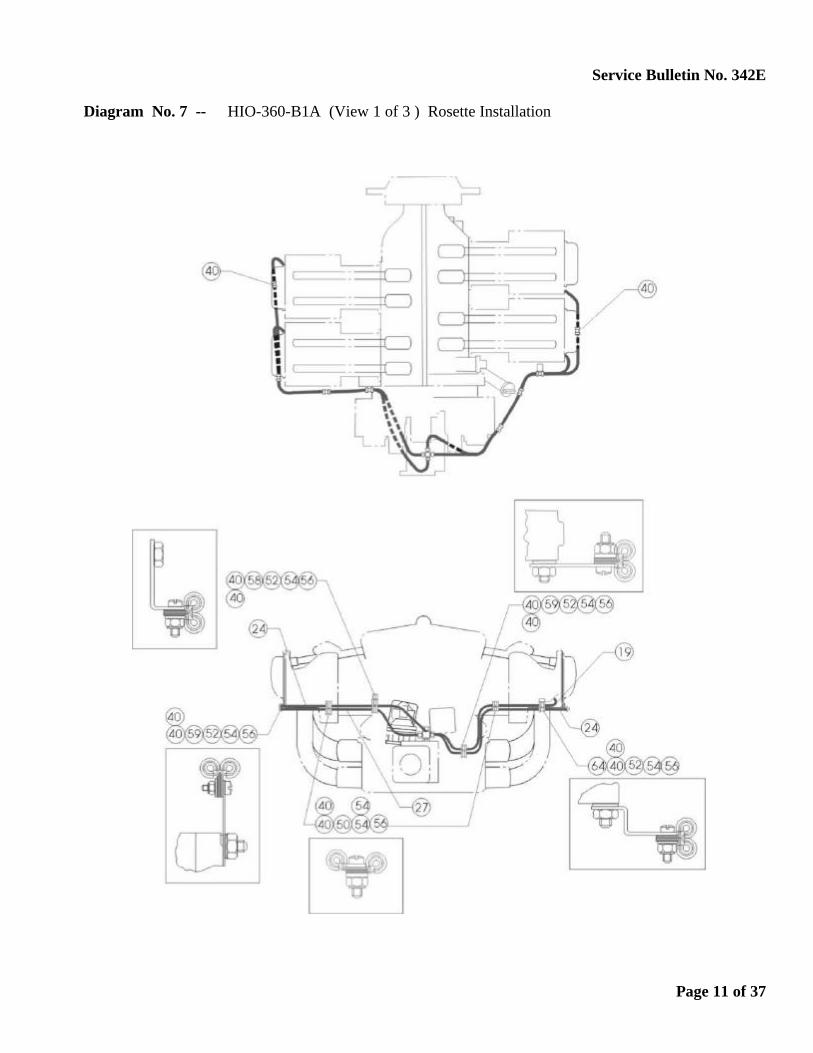
Diagram No. 7 -- HIO-360-B1A (View 1 of 3 ) Rosette Installation
Page 11 of 37

Service Bulletin No. 342E
Diagram No. 8 -- HIO-360-B1A (View 2 of 3) LW-12155 Manifold Assy., Fuel
Page 12 of 37
Service Bulletin No. 342E
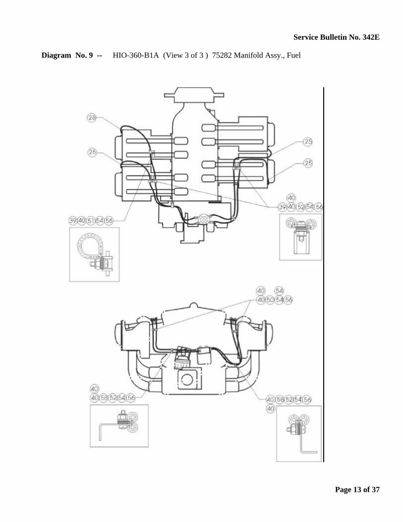
Diagram No. 9 -- HIO-360-B1A (View 3 of 3 ) 75282 Manifold Assy., Fuel
Page 13 of 37
Service Bulletin No. 342E
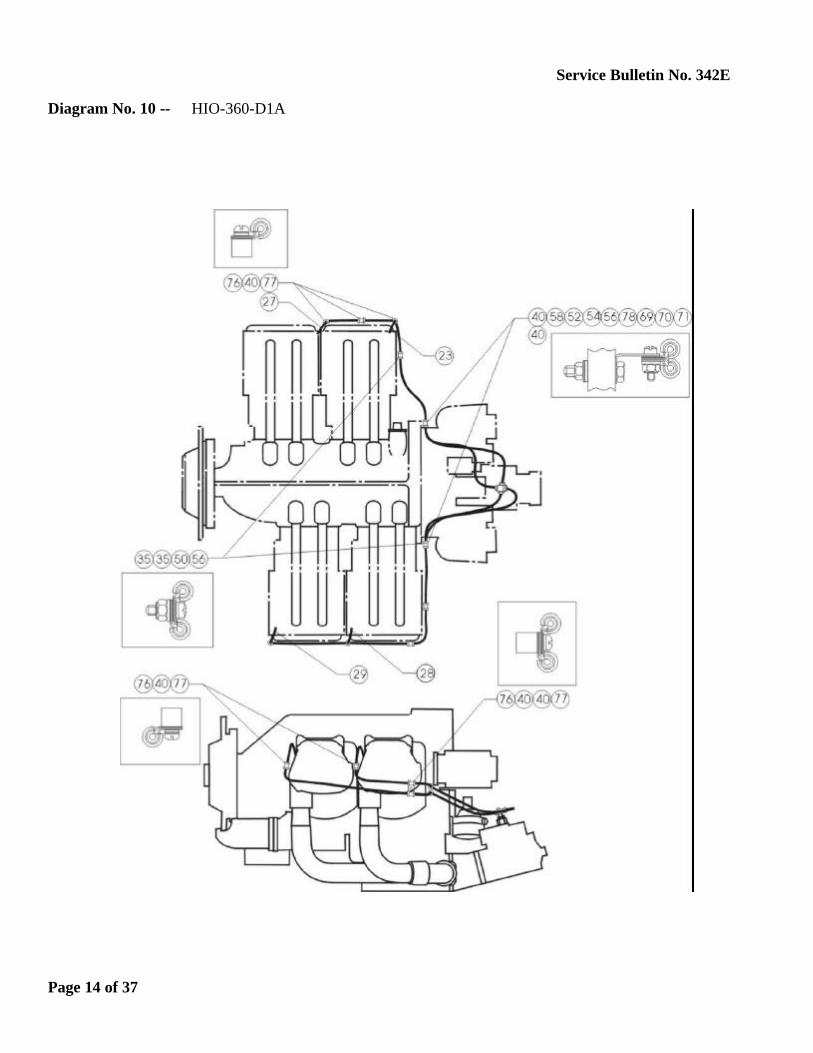
Diagram No. 10 -- HIO-360-D1A
Page 14 of 37
Service Bulletin No. 342E
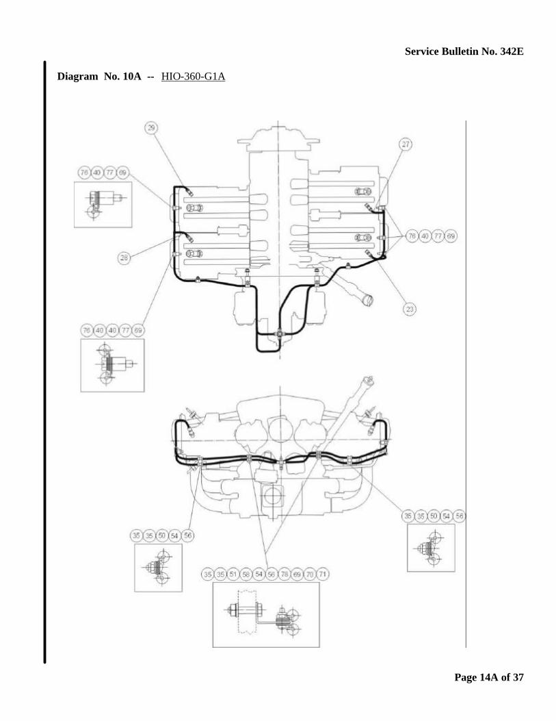
Diagram No. 10A -- HIO-360-G1A
Page 14A of 37

Service Bulletin No. 342E
Diagram No. 11 -- AIO-320-A1B, B1B, C1B AIO-360-A1A, A1B, B1B
Page 15 of 37

Service Bulletin No. 342E
Diagram No. 12 -- TIO-360-C1A6D (View 1 of 3)
Page 16 of 37
Service Bulletin No. 342E
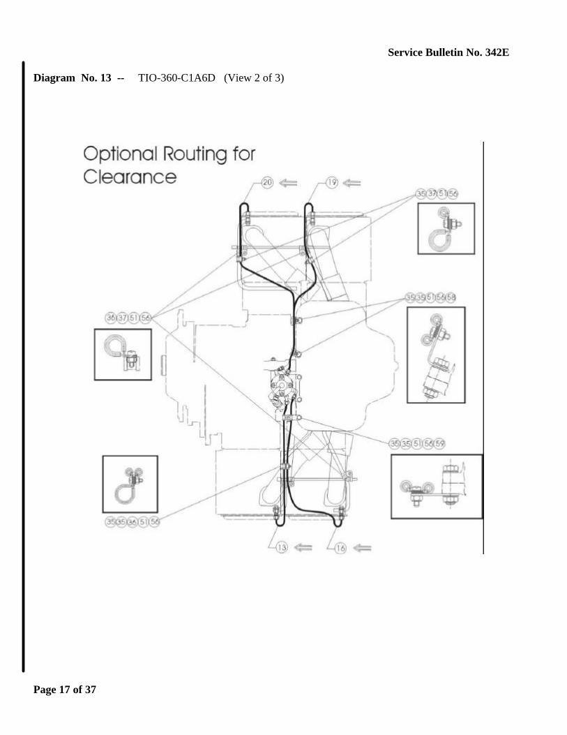
Diagram No. 13 -- TIO-360-C1A6D (View 2 of 3)
Page 17 of 37
Service Bulletin No. 342E
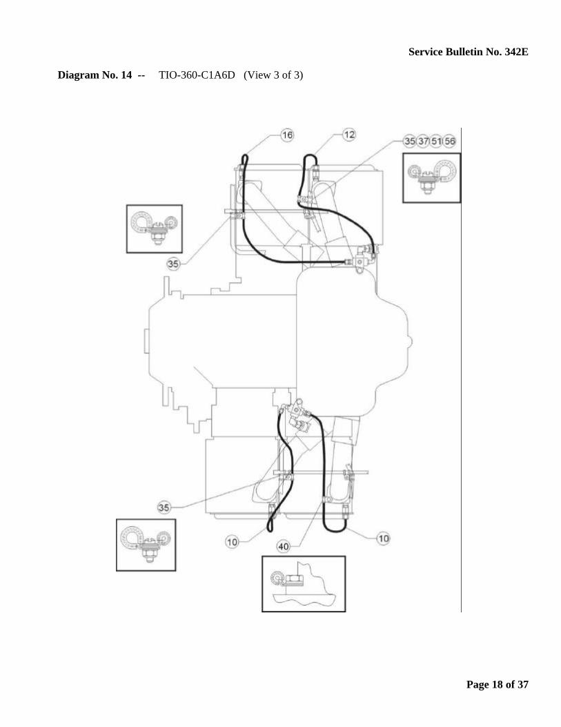
Diagram No. 14 -- TIO-360-C1A6D (View 3 of 3)
Page 18 of 37

Service Bulletin No. 342E
Diagram No. 15 -- IVO-360-A1A
Page 19 of 37
Service Bulletin No. 342E
Diagram No. 16 -- IGO-480-A1B6
Page 20 of 37
Service Bulletin No. 342E
Diagram No. 17 -- IO-540-C4D5D, G1C5, K1A5, K1A5D, K1B5, K1F5, K1F5D, K1G5, K1G5D, K1H5, K1J5D, K1K5, AA1B5
Page 21 of 37

Service Bulletin No. 342E
Diagram No. 18 -- IO-540-A1A5, G1A5, G1B5, G1D5, G1E5, G1F5, K1A5, K1B5, K1C5, K1D5, K1E5, K1E5D, K1F5, K1H5, K1J5, P1A5, S1A5, T4A5D, T4B5, T4B5D, T4C5D, AA1A5 TIO-540-U2A, AE2A, AH1A LTIO-540-U2A
Page 22 of 37

Service Bulletin No. 342E
Diagram No. 18A -- IO-540-AE1A5
Page 22A of 37

Service Bulletin No. 342E
Diagram No. 19 -- AEIO-540-D4D5 TIO-540-AF1A, AF1B, AG1A, AA1AD, AB1BD
Page 23 of 37

Service Bulletin No. 342E
Diagram No. 19A -- IO-540-AB1A5 TIO-540-AK1A
Page 23A of 37

Service Bulletin No. 342E
Diagram No. 20 -- IO-540-AC1A5 TIO-540-AJ1A
Page 24 of 37
Service Bulletin No. 342E
Diagram No. 21 -- IO-540-A1A5, C1B5, C4B5, C4D5D, D4A5, J4A5, L1C5, AB1A5 TIO-540-C1A, E1A, G1A, AB1AD AEIO-540-D4A5, D4B5, L1B5, L1B5D, L1D5
Page 25 of 37

Service Bulletin No. 342E
Diagram No. 21A -- IO-540-N1A5, R1A5, V4A5, V4A5D, W1A5, W1A5D, W3A5D
Page 25A of 37
Service Bulletin No. 342E
Diagram No. 22 -- IO-540-B1A5, B1C5, E1A5, E1B5
Page 26 of 37
Service Bulletin No. 342E
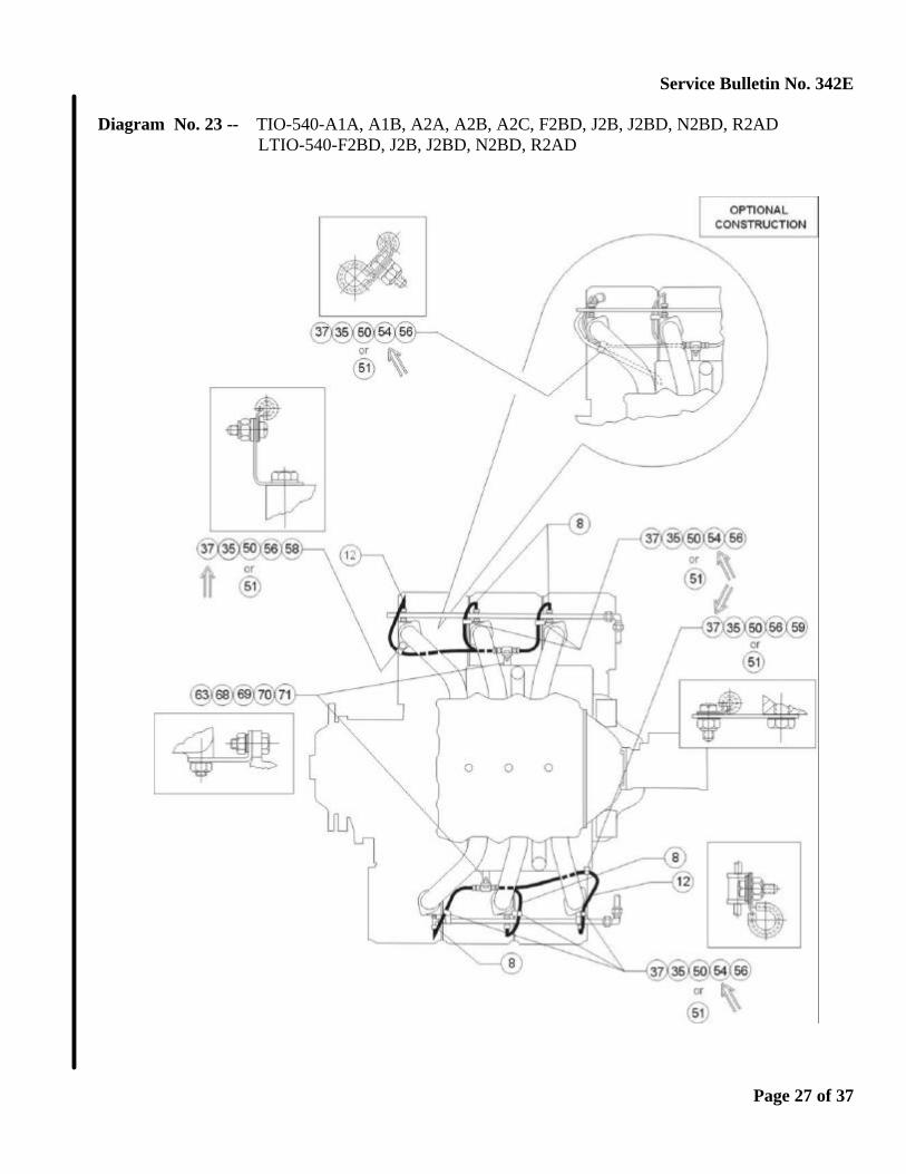
Diagram No. 23 -- TIO-540-A1A, A1B, A2A, A2B, A2C, F2BD, J2B, J2BD, N2BD, R2AD LTIO-540-F2BD, J2B, J2BD, N2BD, R2AD
Page 27 of 37
Service Bulletin No. 342E
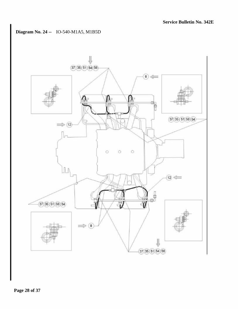
Diagram No. 24 -- IO-540-M1A5, M1B5D
Page 28 of 37

Service Bulletin No. 342E
Diagram No. 24A -- IO-540-M1C5
Page 28A of 37

Service Bulletin No. 342E
Diagram No. 25 -- TIO-540-S1AD
Page 29 of 37
Service Bulletin No. 342E
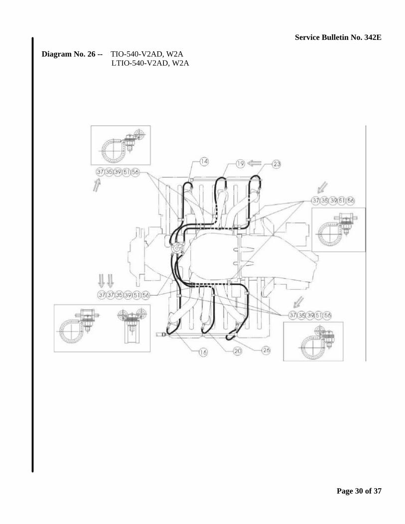
Diagram No. 26 -- TIO-540-V2AD, W2A LTIO-540-V2AD, W2A
Page 30 of 37
Service Bulletin No. 342E
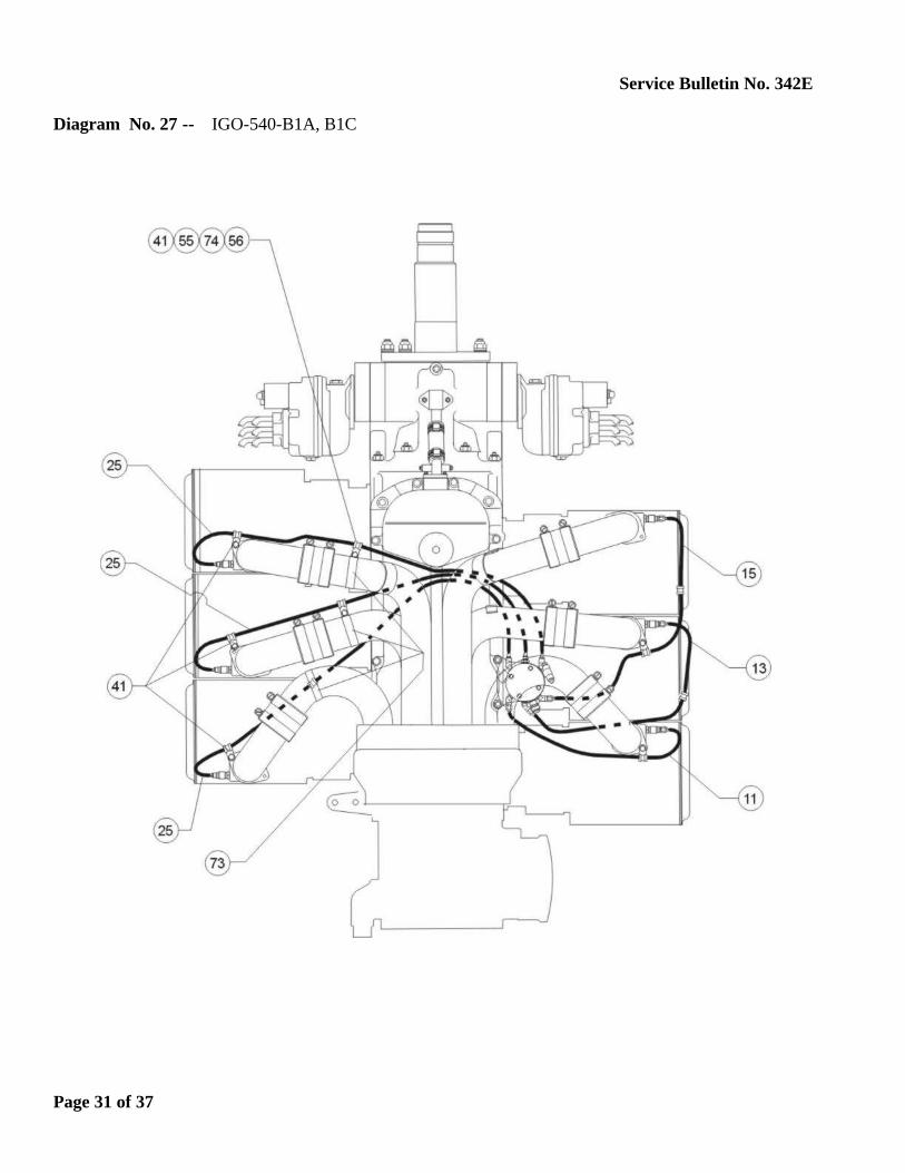
Diagram No. 27 -- IGO-540-B1A, B1C
Page 31 of 37

Service Bulletin No. 342E
Diagram No. 28 -- IVO-540-A1A
Page 32 of 37
Service Bulletin No. 342E
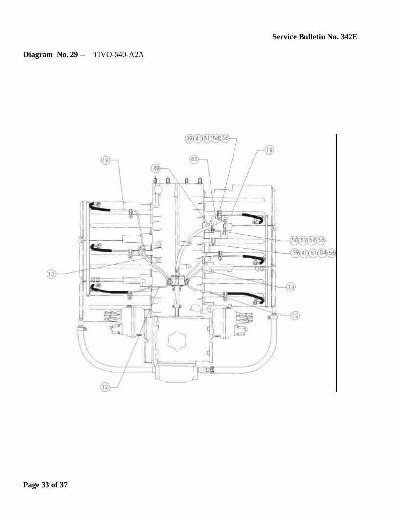
Diagram No. 29 -- TIVO-540-A2A
Page 33 of 37
Service Bulletin No. 342E
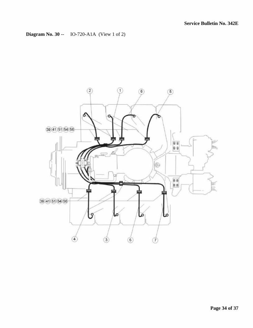
Diagram No. 30 -- IO-720-A1A (View 1 of 2)
Page 34 of 37

Service Bulletin No. 342E
Diagram No. 31 -- IO-720-A1A (View 2 of 2), A1B, D1B, D1BD, D1C, D1CD
Page 35 of 37
Service Bulletin No. 342E
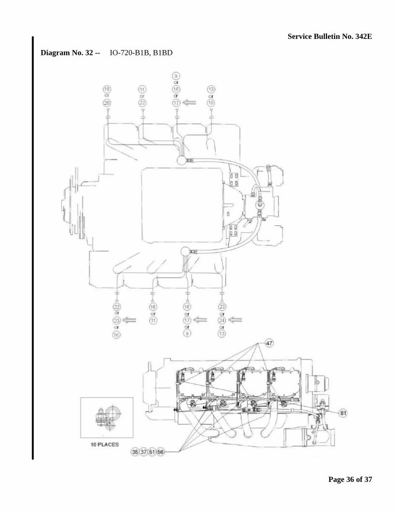
Diagram No. 32 -- IO-720-B1B, B1BD
Page 36 of 37

Service Bulletin No. 342E
Diagram No. 33 -- IO-720-C1B
Page 37 of 37