wilberforce pendulum (one or two weights) pendulum.pdf · wilberforce pendulum (one or two weights)...
TRANSCRIPT

1
Wilberforce Pendulum (One or two weights)
For a 1 weight experiment do Part 1 (a) and (b). For a 2 weight experiment do Part1 and Part 2 Recommended readings: 1. R.A.Serway and J.W.Jewett, Jr. Physics for Scientists and Engineers 8th ed. (Thomson, 2010). Chapters 12 and 15. 2. http://faraday.physics.utoronto.ca/IYearLab/WilberforceRefBerg2of8.pdf – the most complete description of the phenomenon of Wilberforce pendulum. Preparatory Questions: 1. The formula for the period of harmonic vibration of a mass M suspended from a massless
spring of the spring constant k differs from the expression for the period of vibration of the mass M on the spring with non-zero mass m with same spring constant k. Without deriving the formulas, give a reasonable guess on the relationship between the period of vibration on the massless spring and the period of vibration on the spring with finite mass when m < M.
2. The Hooke’s law is applicable to springs and solid bodies, such as strings, rods, etc. For a rod, the Hooke’s law is usually given as
LL
AYF
0
,
where Y is the Young’s modulus responsible for elastic properties of the material of the rod; A is the cross-sectional area of the rod; L0 is the initial non-stressed length of the rod; and ΔL is the elongation of the rod under the force F. Can this expression of the Hooke’s law be applied to a spring? Why yes, or why no?
3. Imagine a spring hanging vertically with a mass attached at the bottom end. In what kind of vibration - liner along the vertical direction or rotational about the vertical axis, does the wire of the spring experience more tensile stress than the shear stress?
1. Introduction The Wilberforce pendulum (also known as a Wilberforce spring) was invented by British physicist Lionel Robert Wilberforce around 1896 in Cavendish Laboratory. This pendulum consists of a mass on a vertical spring that cannot be treated as a massless object and can participate in rotational motion about the vertical axis together with the attached mass. Being properly adjusted the Wilberforce pendulum demonstrates periodic transfer of energy between translational and rotational modes of vibration.

2
In this simple interpretation of motion of the system “mass on the massless spring” kinetic energy belongs to the mass attached, while the spring acts as a depot of potential energy. The Wilberforce spring should be treated as an extended body with mass Ms, whose center of mass is also vibrating. The period Tv of vertical vibration of the mass M on this spring with the spring constant k is given by
k
MM
T
s
v32
(1)
When the pendulum is undergoing rotational motion, the period of the rotational oscillation Tr depends on the elastic properties of the particular spring that are represented by the torsion constant κ, on the moment of inertia of the spring Is and on the moment of inertia I of the mass (moveable masses plus frame system) on the end of the spring. The period Tr is given by an equation similar to the equation (1):
32
s
r
II
T
(2)
To understand the origin of the torsion constant κ, it is useful to remember resemblance between dynamical quantities in translational motion and in rotational motion. If mass is replaced my moment of inertia, force is replaced by torque, and the linear displacement by angular displacement, it can be easily obtained that the Hooke’s law for the rotational motion can look like the following:
τ = -κθ (3)
The moment of inertia I in Eq.2 is a compound quantity that includes the moments of inertia of all pieces of rotating system suspended from the spring. There are only two movable masses on a horizontal threaded rod that can change the moment of inertia of the rotating system. So, the Eq. 2 can be rewritten as
20 2
2mdI
Tr
(4)
where I0 is a sum of moments of inertia of rotating system including the spring; m is the mass of each of two movable asses on a horizontal rod; and d is the distance between the axis of rotation and the center of mass of each movable mass. We will treat the movable masses as point masses contributing into the systematic error in calculation of the moment of inertia according to the parallel-axes theorem.
In this system, the two types of harmonic motion, translational and rotational, are not entirely independent; there is a slight coupling between them. This results from the fact that the spring has a slight tendency to coil and uncoil as it is extended or compressed. The Wilberforce spring is thus an example of two weakly coupled resonant systems; the other example being a coupled pendulum that consists of two simple pendulums of similar length with a spring joining the upper parts of their strings. Thus, the Wilberforce spring is a good way to study mechanical resonance in coupled systems.
3
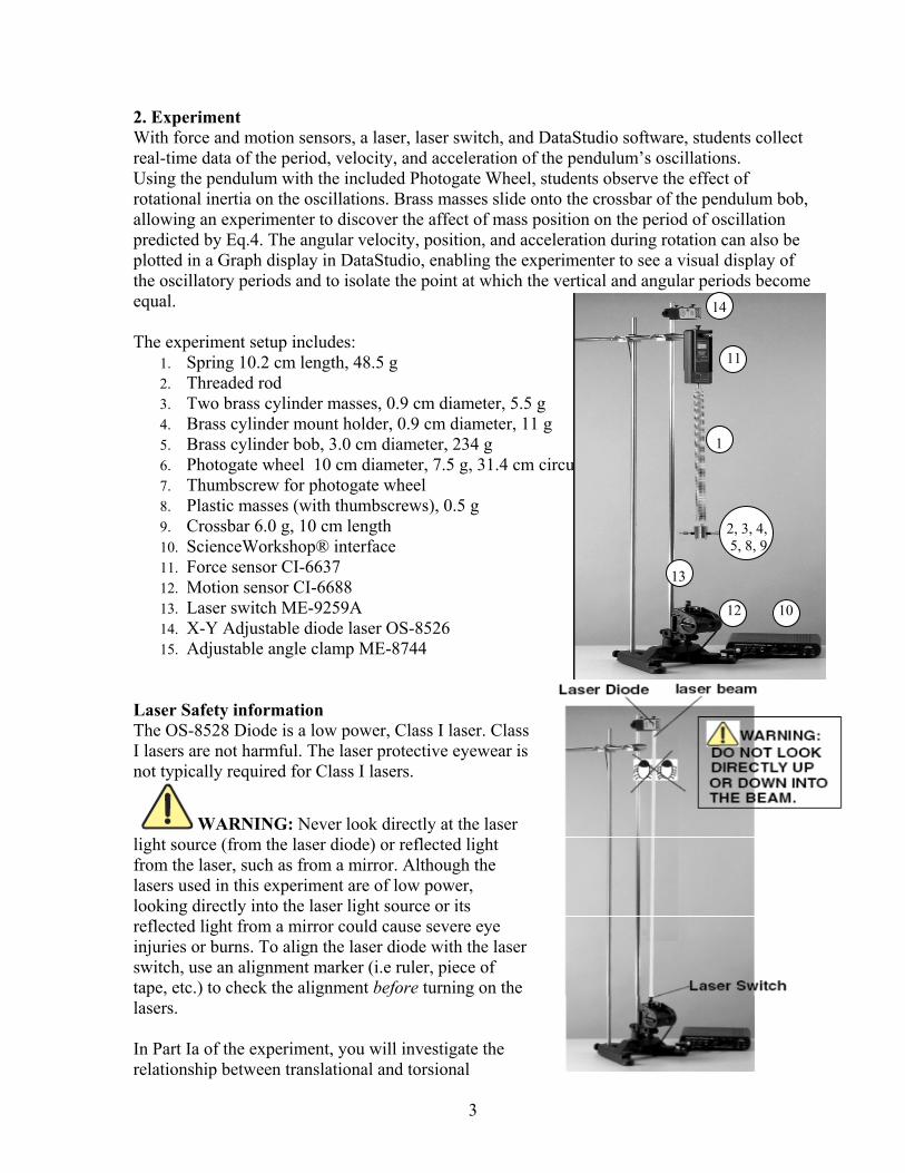
2. Experiment With force and motion sensors, a laser, laser switch, and DataStudio software, students collect real-time data of the period, velocity, and acceleration of the pendulum’s oscillations. Using the pendulum with the included Photogate Wheel, students observe the effect of rotational inertia on the oscillations. Brass masses slide onto the crossbar of the pendulum bob, allowing an experimenter to discover the affect of mass position on the period of oscillation predicted by Eq.4. The angular velocity, position, and acceleration during rotation can also be plotted in a Graph display in DataStudio, enabling the experimenter to see a visual display of the oscillatory periods and to isolate the point at which the vertical and angular periods become equal. The experiment setup includes:
1. Spring 10.2 cm length, 48.5 g 2. Threaded rod 3. Two brass cylinder masses, 0.9 cm diameter, 5.5 g 4. Brass cylinder mount holder, 0.9 cm diameter, 11 g 5. Brass cylinder bob, 3.0 cm diameter, 234 g 6. Photogate wheel 10 cm diameter, 7.5 g, 31.4 cm circumference 7. Thumbscrew for photogate wheel 8. Plastic masses (with thumbscrews), 0.5 g 9. Crossbar 6.0 g, 10 cm length 10. ScienceWorkshop® interface 11. Force sensor CI-6637 12. Motion sensor CI-6688 13. Laser switch ME-9259A 14. X-Y Adjustable diode laser OS-8526 15. Adjustable angle clamp ME-8744
Laser Safety information The OS-8528 Diode is a low power, Class I laser. Class I lasers are not harmful. The laser protective eyewear is not typically required for Class I lasers.
WARNING: Never look directly at the laser light source (from the laser diode) or reflected light from the laser, such as from a mirror. Although the lasers used in this experiment are of low power, looking directly into the laser light source or its reflected light from a mirror could cause severe eye injuries or burns. To align the laser diode with the laser switch, use an alignment marker (i.e ruler, piece of tape, etc.) to check the alignment before turning on the lasers. In Part Ia of the experiment, you will investigate the relationship between translational and torsional
14 11 1 2, 3, 4, 5, 8, 9
13 12 10

4
oscillatory motion in a pendulum with a brass mass hanging from a spring; determining resonance and measuring energy transfer at resonance. In Part Ib, you will examine the effect of the inertia from a photogate wheel on a pendulum In Part II you will investigate the normal mode; calculate the Young’s modulus and shear modulus of the material of the wire of the spring. Setup without the Photogate Wheel:
Screw a small, plastic mass over each side on the horizontal cross bar jutting from the large brass mass.
Screw on a brass mass on each side of the crossbar.
Use a measuring tape to ensure each brass mass is equidistant from the bob in the center.
Use two more plastic masses to hold the brass masses in place (Figures 1a and 1b). Setup with Photogate Wheel:
Use a thumbscrew provided to attach the wheel to the bottom of the large brass mass.
Screw two plastic masses onto each side of the brass cylinder bob (Fig. 2).
Add another plastic mass to each side, allowing a gap between the second mass and the first mass.
Finally, add a third plastic mass to each side; the third mass is to hold the second mass in place.
Note: When using the Photogate Wheel, do not put the brass masses on the crossbar. Note: When using the Photogate Wheel, use the plastic masses instead of the brass masses on the crossbar. If you attach the disk, you must use the plastic, black masses on the crossbar because the brass masses have too much rotational inertia. To change the period of the pendulum’s oscillations, change the distance of the masses from the center. DataStudio Setup Instructions 1. Connect the sensors to the ScienceWorkshop interface, as follows: a) Plug the stereo plugs on the Motion Sensor to digital channels 1 and 2 on the interface b) Plug the DIN connector on the Force Sensor to any analog channel on the interface c) Plug the stereo plug of the Laser Switch into digital channel 3 on the ScienceWorkshop interface. 2. Open DataStudio and select “Create Experiment.” 3. Click the Setup button to open the Experiment Setup window.
FIG.2: Photogate Wheel attached to the brass cylinder
(a) (b) FIG.1

5
4. In the Sensors list, drag the Motion Sensor icon to the first two digital channels on the picture of the interface. Drag the Force Sensor to the same channel you have the sensor plugged into on the picture of the interface.
5. Select the Smart Pulley from the Sensors list and drag it to the third digital channel on the interface. [For the Laser Switch, you will use the Smart Pulley icon (instead of the Laser Switch icon) in the Setup window. If you use the Laser Switch icon, you need to set up a timing scheme in DataStudio.]
6. Double click on the Smart Pulley icon to open the Sensor Properties dialog. In the Measurement tab, click to check the Angular Position (rad), Angular Velocity (rad/s), and Angular Acceleration (rad/s/s) options.
7. Your experiment is set up in DataStudio. When you are ready to begin the experiments, on the main toolbar, click the Start button to begin recording data. You will obtain six graphs: position vs. time, velocity vs. time, force vs. time, angular position vs. time, angular velocity vs. time, and angular acceleration vs. time. Part Ia: Effect of Mass on Oscillatory Periods in a Pendulum
1. Set up equipment as in Fig.1. 2. Open ‘Data Studio’ and make sure the channel 1 and 2 is for motion sensor, channel 3
is for laser switch (called Smart Pulley), and analog channel A is for force sensor (When you click on channel 3, there usually is not an option for the laser switch, to fix this, you must go to File -> Options -> Edit… -> Sensors -> Check off ‘Smart Pulley’).
3. When you designate smart pulley, go to Measurements -> Check off ‘Angular Velocity, Ch 3’ and then switch the units from deg/s to rad/s for simplicity.
4. Then drag ‘Postion, Ch 1&2 (m)’, ‘Angular Velocity, Ch 3 (rad/s)’, and ‘Force, Ch A (N)’ to one graph
5. Move the position of the masses on the crossbar until they are equidistant from the centermost point on the pendulum bob.
6. Record the weight of the brass masses in Table 1. 7. With a metric measuring tape, measure the distance of each mass from the center point
on the bob. Record your measurement in Table 1. 8. To start making the measurements, press ‘Start’ and then pull the brass bob down from
its equilibrium position. Observe the data in real-time as the pendulum oscillates. 9. Change the distance of each brass mass in order to get a clear reading. Maybe few trials
are required to witness a clear transfer of energy between two forms of oscillation. 10. Move the masses on the crossbar to a new position and repeat steps 8 through 10. Move
the masses on the crossbar to various positions to see the affect that mass position has on the period and angular velocity.
11. Adjust the masses to observe resonance when the periods of the vertical and rotational oscillations are the same. At resonance the amplitudes of both rotation and translation will alternately be at a maximum.
Note: The periods of the vertical and rotational oscillations must be exactly the same (quantitatively equal) for the oscillations to switch completely between the vertical and rotational modes. If the periods are not equal, adjust the masses on the crossbar and pull the pendulum again. This may take a few runs of trial and error.
6
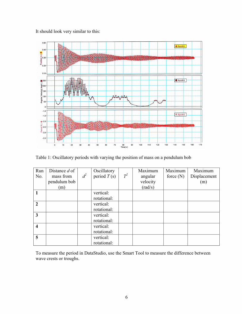
It should look very similar to this:
Table 1: Oscillatory periods with varying the position of mass on a pendulum bob
To measure the period in DataStudio, use the Smart Tool to measure the difference between wave crests or troughs.
Run No.
Distance d of mass from
pendulum bob (m)
d2
Oscillatory period T (s)
T2
Maximum angular velocity (rad/s)
Maximum force (N)
Maximum Displacement
(m)
1 vertical: rotational:
2 vertical: rotational:
3 vertical: rotational:
4 vertical: rotational:
5 vertical: rotational:

7
Part Ib: The Effect of Rotational Inertia on Oscillatory Periods from a Pendulum Swing 1. When setting up the apparatus, attach the photogate wheel to the brass bob using the
screw for the photogate wheel as in Fig. 2. 2. Make sure to remove the brass masses and only work with plastic masses 3. Then follow PART I from step 2. 4. Record data in Table 2.
Table 2: The Effect of Rotational Inertia on a Pendulum’s Oscillation
Energy Transfer at Resonance The energy of the translational motion can be determined from the linear amplitude and the rotational energy - from the angular amplitude if the force constant k and the torsion constant κ are known.
a) Measure the maximum linear and rotational amplitudes at resonance. b) Plot T2 versus d2and determine the torsion constant κ using equation (4). c) Determine the force constant k by hanging the provided masses from the end of the spring with the special hook and pointer. d) Calculate the maximum translational and rotational energies and compare. Give energy value with its uncertainty.
PART II. Some additional theory concerning normal modes is required for Part II. The motion that the Wilberforce pendulum experiences at any given time is a combination of both translational and rotational motion. Just as the position of an object can be treated as a vector i.e. (x, y) with vertical and horizontal components, we can represent a given state of motion of the Wilberforce pendulum as the vector (z, θ) with linear (vertical) and angular components. It turns out that any position that the pendulum might occupy during its motion is created by a linear combination of two such vectors. That is: (z, θ) = av1 + bv2 where v1 and v2

8
both have vertical and angular components. Both of these vectors have their own frequency. At any given time, the position of the pendulum may be a multiple of either v1 or v2 alone or it may be a mixture of both. When the motion of the oscillator is just due to one of these vectors but not the other, it is said to be oscillating in a normal mode. Physically, this means that both types of motion occur with the same frequency, and they pass through their equilibrium positions at the same time If the system is set in motion in one of its normal (eigen) modes, then it will continue to oscillate without any change in its translational or rotational amplitude (except that both amplitudes exponentially decay due to friction). The two normal modes have different frequencies, one higher and one lower than the resonant frequency. The difference in these two frequencies equals the beat frequency observed at resonance for energy transfer between translation and rotation. If equations (1) and (2) are rewritten as
k
MT eff
trans 2 and
effrot
IT 2
then the normal modes may be constructed [R.E. Berg and T.S. Marshall, Wilberforce Pendulum Oscillations and Normal Modes, Am. J. Phys., 59, 32-38 (1991)] by setting )
z0 =eff
eff
M
I θ0 (5)
where z0 and θ0 are the initial amplitudes for translation and rotation respectively. The Normal Modes
Determine Meff From your graph of T2
rot versus d2 determine I0 and hence Ieff Adjust the system for resonance and measure the beat frequency or the frequency for
the transfer of energy between the two types of motion. Using equation (5), determine the values of the amplitudes for a normal mode. Hint:
choosing θ0 = π and then determining z0 is experimentally convenient. Set the system in motion with these values and observe whether or not it is oscillating in a normal mode.
Measure the frequencies of the normal modes. Do your results agree with the value for the beat frequency observed above?
For the same θ0, change z0 and investigate the effect of this change on the motion.
Checking Assumptions Equation (1), [and by analogy, equation (2)] is an approximation which becomes better as M becomes large compared to Ms. Compare your measured value of Ttrans
with the value calculated using (1). You can increase M by sliding a slotted mass onto the top of the Wilberforce pendulum. Is (1) a good approximation? Shear Modulus The shear modulus S is related to the spring constant k by the formula
4
34
r
NRkS

9
where r is the radius of the wire, R is the radius of the helical coil and N is the number of turns in the coil. Calculate the shear modulus for the material of the spring and suggest what the material might be by comparing your value to those you can find in the handbook in the labs. Young’s Modulus Young’s modulus Y is related to the torsion constant κ for the spring as a whole by the formula
4
8
r
NRY
Calculate Young’s modulus for the material of the spring and suggest what the material might be by comparing your value to those you can find in the Physics and Chemistry handbook in the labs. .
Developed and first tested in May - June 2012 by Ms. Elisse Magnuson (PHY152) and Mr. Tony Kang,
SURF students of the Department of Physics supervised by Dr. Natalia Krasnopolskaia
Revised and updated by Natalia Krasnopolskaia in October 2012