wifi/lan video intercom - bft automation · intercom at the gate and position the antenna to check...
TRANSCRIPT
1 | P a g e
Installation Instructions For
WiFi/LAN Video Intercom
Manual Version 2
BFT Americas 6100 Broken Sound Parkway N.W. Suite 14, Boca Raton, FL 33487
www.bft-usa.com
Toll Free: 877-995-8155
Office: 561-995-8155
Fax: 561-995-8160

2 | P a g e
Index
Section Pages
Android Configuration 3-6 iphone Configuration 7-11
Range and range testing 12-14 Installation 15
Power Supply 15 Wiring 16
Relay Output 17 Keypad Overview 17
Basic Keypad Programming 18 Full Keypad Programming 18
Using the Keypad 19 Adding Additional Smart Phones & Devices 20-21
Using the Intercom on Android 22 Using the Intercom on iphone 23
Other Options for using the App 24 Fault Finding 25
Revision changes 27
3 | P a g e
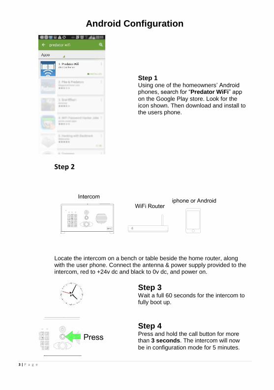
Android Configuration
Step 1 Using one of the homeowners’ Android phones, search for “Predator WiFi” app
on the Google Play store. Look for the icon shown. Then download and install to the users phone.
Step 2
Locate the intercom on a bench or table beside the home router, along
with the user phone. Connect the antenna & power supply provided to the intercom, red to +24v dc and black to 0v dc, and power on.
Step 3 Wait a full 60 seconds for the intercom to fully boot up.
Step 4 Press and hold the call button for more than 3 seconds. The intercom will now
be in configuration mode for 5 minutes.

4 | P a g e
Step 5 Step 6 Enter settings on the phone, select WiFi and scan for networks. The
phone should detect the intercom. The network name will be BELL-
XXXXX)
Enter the following password… 123456789.
Step 7 Step 8 Now open the WiFi-Predator App on
the phone and select as shown to add intercom.
On the next screen, select search as shown.

5 | P a g e
Step 9 Step 10 The phone should then find the
device. Select it as shown. On the next screen the intercom should
be showing online status. Select the settings button.
Step 11 Step 12 Enter WiFi settings as shown. Select option to manage wifi networks
and the intercom will now scan networks in the area.

6 | P a g e
Step 13 Step 14 Select the network which the home
owner is normally using. Enter the home owner’s WiFi password
and press DONE. The intercom should now re-boot and the phone should then re-connect to the normal wifi network.
2 mins…
Step 15 Step 16
Wait 2 minutes for the intercom to come back online, and then open the app. The intercom should be showing
status online.
You may now press the call button and check that the intercom calls the phone
sucessfully.
You are now ready to range test the intercom in the location which it will be used!

7 | P a g e
I-phone Configuration
Step 1 Using one of the homeowners’ iphones, search for “Predator-WiFi”
app on the Apple Store. Look for the icon shown. Then download and install to the users phone.
Step 2
Locate the intercom on a bench or table beside the home router, along with the user phone. Connect the antenna & power supply provided to the intercom, red to +24v dc and black to 0v dc, and power on.
Step 3 Wait a full 60 seconds for the intercom to fully boot up.
Step 4 Press and hold the call button for more than 3 seconds. The intercom
will sound a long tone, and now be in configuration mode for 5 minutes.
8 | P a g e
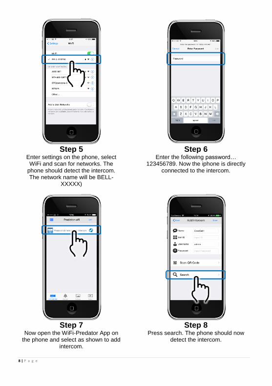
Step 5 Step 6 Enter settings on the phone, select WiFi and scan for networks. The
phone should detect the intercom. The network name will be BELL-
XXXXX)
Enter the following password… 123456789. Now the iphone is directly
connected to the intercom.
Step 7 Step 8 Now open the WiFi-Predator App on
the phone and select as shown to add intercom.
Press search. The phone should now detect the intercom.

9 | P a g e
Step 9 Step 10 The intercon should now have been
detected. Select as shown. Now the app should show the bell ID,
default username & password details. Press DONE as shown.
Step 11 Step 12 Enter Settings as shown. Select option to manage wifi networks
and the intercom will now scan networks in the area.

10 | P a g e
Step 13 Step 14 Select the network which the home owner is normally using. Note the scan button at top if the iphone does not automatically scan for networks.
Enter the home owner’s WiFi password and press JOIN. Now power off and on the intercom.
2 mins…
Step 15 Step 16
Wait 2 minutes for the intercom to come back online, and then open the app. The intercom should be showing
status online.
You may now press the call button and check that the intercom calls the phone sucessfully. Note: It may take several minutes for the operation to
fully stabalise. Note: Because of restrictions by Apple, your iphone will receive a notification message first. If your screen is locked, you must swipe the notification banner, then unlock the screen before the intercom app can begin calling the phone in full.

11 | P a g e
On the iphone, go to settings > Notifications > Predator-wifi. We recommended that the Alerts option is selected as shown, and that all options shown are turned on.

12 | P a g e
Range Test
Before fully installing this product, it is strongly recommended to temporarily power the
intercom at the gate and position the antenna to check that it is within range of the WiFi router. The manufacturer will not give a full refund for a product which is not returned in brand new condition.
Once the antenna is in position and the unit has been powered up for more than 2 minutes, use the users phone inside the house to check for range as follows..
Check that the network which it is connected to is showing at least 20% strength. If it is
not connecting, or is lower than 20%, then corrective action must be taken at this stage.
Suggestions are as follows..
1. Ensure antenna is mounted as high as possible on the pillar or post.
13 | P a g e
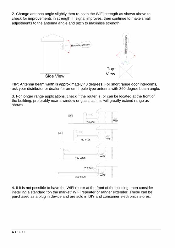
2. Change antenna angle slightly then re-scan the WiFi strength as shown above to
check for improvements in strength. If signal improves, then continue to make small
adjustments to the antenna angle and pitch to maximise strength.
TIP: Antenna beam width is approximately 40 degrees. For short range door intercoms,
ask your distributor or dealer for an omni-pole type antenna with 360 degree beam angle.
3. For longer range applications, check if the router is, or can be located at the front of the building, preferably near a window or glass, as this will greatly extend range as shown.
4. If it is not possible to have the WiFi router at the front of the building, then consider installing a standard “on the market” WiFi repeater or ranger extender. These can be purchased as a plug in device and are sold in DIY and consumer electronics stores.

14 | P a g e
5. For even greater range, you can alternatively install homeplug power line adaptor kits, which extend LAN over mains wiring. Simply plug one into the router and the other into the intercom call box.
Note: The router needs to be on the same trip device as the power to the intercom for
this technique to work. Always consult a professional electrician regarding mains wiring.

15 | P a g e
Installation
Assuming satisfactory operation at full range, you are ready to fully install the product.
Mount the intercom at the desired height for pedestrian or car users. The camera angle is
wide at 110 degrees to cover most scenarios.
Tip: Do not drill holes in the wall with the intercom in positon, otherwise dust may get
around the camera window and impair the camera view.
Power supply
If possible, locate the power supply as close as possible to the intercom.
24v dc
1amp power
supply
14 Gauge Power cable
25 feet max
Call box
TIP: Most technical calls received are due to installers using thin gauge cable over
longer cable runs. This intercom has a peak current demand of up to 2 amps.
Up to 2 metres (6 feet) – Use minimum 0.5mm2 (20 gauge)
Up to 4 metres (12 feet) – Use minimum 1mm2 (16 gauge)
Up to 8 metres (25 feet) – Use minimum 1.5mm2 (14 gauge)

16 | P a g e
Wiring Connect power as shown. Please use only the power adaptor provided.
Depending on your requirements, the intercom and keypad have both normally closed
and normally open output contacts for connection to existing electric locks or gate
automation controllers.
Note: The manufacturer can only support the use, operation and functionality of the
intercom and keypad themselves. Professional wiring to door release or automatic gate
systems is the responsibility of the installer. Please consult a security integrator for
further support.

17 | P a g e
Relay output The app has an option to switch the relay output from normally open to normally closed.
This is not normally needed because the relay output terminals already have hard
connections for N/O and N/C contacts as standard.
The relay time may need changed to suit lock applications. It is adjustable from 1-9
seconds as shown..
Keypad Overview
This keypad has 3 outputs. The diagram below shows the LED indicators which indicate
programming and relay status information.
ON when incorrect codes entered and outputs are locked out.
1 2 3
4 5 6
7 8 9
* 0 #
SLOW FLASHING - in normal standby mode.
ON in programming mode.
ON when relay 3 activated.
GREEN when output 1 activated.
RED when output 2 activated.
FAST FLASHING – Wrong code entered / error.
TIP: After power up, as a security precaution, the keypad cannot be programmed for 60
seconds. Once this time elapses, you may begin.
TIP: Flashing amber LED is normal standby mode!

18 | P a g e
Basic Keypad Programming
For most installs, it is sufficient to simply enter a single user code as follows..
0 0 0 0 * *
Quick start guide
1) Enter programming mode (amber LED should be ON)
1 0 2 0 0 ? ?? ? #0
2) Enter a new user code...
* *
3) Exit programming mode
4) Enter the new user code to check the relay clicks.
Tip: The engineer code must be the same length as user codes. So if using a 6 digit
engineer code, then user codes must also be 6 digits long etc.
Full Keypad Programming
Enter programming mode..
0 0 0 0 * *
Exit programming mode..
* *
Enter a new ENGINEERS code… Go into programming mode firstly then enter the following sequence…
Location
0 1 ?? ? ?
4-8 digit code Validate
#
Enter or delete new user codes
There are 3 groups of user codes. Group 10 for relay 1, group 20 for relay 2, and group 30 for relay
3. The programming sequence is shown below…
Memory locations
000-999 for relay 1
001-100 for relay 2
001-100 for relay 3
1 0 2 0 0
10= relay 1 codes
(1000 available)
20= relay 2 codes
(100 available)
30= relay 3 codes
(100 available)
? ?? ? #0
2= add code
5= delete code
Pin code 4-8 digits Validate
Example: Add user 31 to have access code 5555 operating relay 2….
2 0 2 0 3 5 55 5 #1
Group 2 Add code Location 31 Pin code 5555 Validate
The unit is now in programming mode. Amber LED on the
keypad should remain permanently on. 0000 is the default
programming passcode.
The unit should exit programming mode and the amber LED
should start flashing again.
Replace ???? with your new ENGINEERS
code.

19 | P a g e
Programming relay output times and modes…
? ? 0 1 -
0 = start / stop toggle mode (latching)
1-99999 = seconds momentary operation
9 9 9 9 9or #
51=relay1
52=relay2
53=relay3
Validate
Delete a user code even if you don’t know the code…
? ? 5 ? ?? #
10=relay1
20=relay2
30=relay3
Delete code ID location to be deleted Validate
Delete an entire group of codes
? ? 0 9 99 #
10=relay1 group
20=relay2 group
30=relay3 group
Super delete code Validate
Programming super user codes… A super user code can activate any of the 3 relays
Location
0 2 ?? ? ?
4-8 digit code Validate
#
Restoring defaults
When in programming mode, you can enter the following sequence…
9 9 99 #
When the master code is forgotten….
1) Wire a push button (or replicate with wire link) across the Egress terminal and (-)GND.
2) Switch off power for 1 minute.
3) Switch ON power.
4) During the first 60 seconds, press the EG button once to enable the function.
5) Enter the following code..
8 0 08 * *
The keypad should now be in programming mode, ready to accept new data.
Using the keypad Using the standard codes… Once you have exited out of programming mode, simply enter the user code.
Using super user codes
?? ? ? # 1 Activate output 1
?? ? ? # 2 Activate output 2
?? ? ? # 3 Activate output 3
20 | P a g e
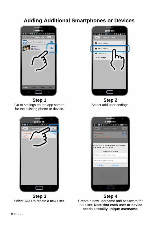
Adding Additional Smartphones or Devices
Step 1 Step 2 Go to settings on the app screen for the existing phone or device.
Select add user settings.
Step 3 Step 4
Select ADD to create a new user. Create a new username and password for that user. Note that each user or device
needs a totallly unique username.

21 | P a g e
Step 5 Step 6
On the new phone, open the app
and press to ADD Intercom. Enter the BELL ID (Copy from the existing
connected device) or press search to find the device, enter new user name and passcode,
and press DONE. The new device should now be added.
22 | P a g e
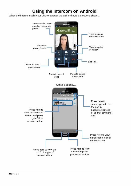
Using the Intercom on Android When the intercom calls your phone, answer the call and note the options shown..
Other options…

23 | P a g e
Using the Intercom on iPhone When the intercom calls your phone, answer the call and note the options shown.
Note: Apple devices will require the user to accept and allow a notification message first,
before the app can be successfully used.
From a locked screen…
1. Swipe the message 2. Screen shown after unlock 3. Swipe to answer.
Receiving a call when the screen is not locked operates as follows…
1. Accept the message. 2. Screen shown afterwards. 3. Swipe to answer.
24 | P a g e
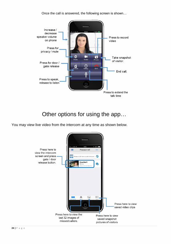
Once the call is answered, the following screen is shown…
Other options for using the app…
You may view live video from the intercom at any time as shown below.

25 | P a g e
Fault Finding
The 3 most common cause of failures on the wifi intercom are as follows…
1. Unstable wifi network or excessive network traffic.
2. Range too long causing wifi drop out intermittently.
3. Excessively long power cable run from the 24v dc adaptor to the intercom causing
poor range, no video, long connection times, or unstable operation.
4. Using 24v ac to power the device rather than the 24v dc adaptor supplied. This can
damage the intercom.
Q: Unit works in the house, but will not work at the gate.
A: This will either be that the wifi range does not reach the gate, or the power cable is too
long and thin. Please address as per the install manual recommendations.
Q: Unit was working on first phone, but not on second phone.
A: Check that both phones have different usernames and passwords.
Q: Unit works on local WiFi network, but not when my phone is on 3G or 4G.
A: This may be due to slow broadband speeds at your router. Remember, a good
download speed is not useful, as the intercom uploads video to the internet, not
downloads from the internet. Consult your broadband provider, re-start your router.
Minimum recommended upload speed is 0.5 Meg, however this may need to be much
more for heave use networks.
A: This may also be due to firewall settings on some routers or networks. Consult your IT
manager or provider.
Q: Unit goes offline for several minutes when I switch from wifi to 3G/4G.
A: This is normal. Your phone needs time to send its new IP location to the servers,
which is relayed to the intercom.
Q: Volume too low on my phone (cannot hear person at the gate).
A: The volume on your phone is restricted by the size of the loud speaker on the phone.
Try increasing phone volume to maximum. Also check that the call point location is at a
good height for someone to speak directly into the microphone.
Q: The intercom was working, but has stopped working.
A: Check if it is working on another phone. If yes, then restart and re-open the app on the
phone in question.
A: If it is not working on any phones, re-start the router or hub, wait 5 minutes and try
again.
A: Check the intercom still has power (illumination should still be on).
A: Check that the antenna at the gate is not overgrown with bushes or shrubs.
A: Check minimum power cable requirements have been met.

26 | P a g e
Q: On iphone, sometimes the call is not connecting when I try to answer, or ends
prematurely.
A: Go into system settings on the app and increase the calling time to at least 45
seconds and try again.
Q: On iphone, when a call is received and I open the app, the ringing tone
continues after I have answered?
A: This happens when the notification is not accepted first. You must accept the
notification on screen and then allow the app to open itself and then swipe to answer the
call.
Q: I am using iphone, and I do not hear any ringing tone when the intercom calls
me?
A: Check the ringer switch on the iphone is set to the ON position, and check media
volume is set to a high level.
Q: The intercom is working, but I cannot get the electric lock working.
A: If you can hear the intercom relay clicking, and you can prove that the relay is making
contact with a multi-meter, then the problem is not the intercom. It will be either a wiring
problem or some other issue with the lock. Please note that the manufacturer of this
intercom is not in a position to give wiring advice on door access or electric locks. It is
recommended that you consult a professional access control installer for advice.
Before calling technical support for any connectivity issues, try the following…
Power off and on the intercom, the hub, and the phone being used. After 5 minutes, try
using the intercom again.
27 | P a g e
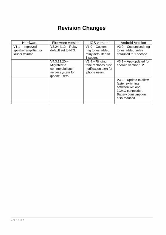
Revision Changes
Hardware Firmware version IOS version Android Version V1.1 – Improved speaker amplifier for louder volume.
V3.24.4.12 – Relay default set to N/O.
V1.0 – Custom ring tones added, relay defaulted to 1 second.
V3.0 – Customised ring tones added, relay defaulted to 1 second.
V4.3.12.20 – Migrated to commercial push server system for iphone users.
V1.4 – Ringing tone replaces push notification alert for iphone users.
V3.2 – App updated for android version 5.2.
V3.3 – Update to allow faster switching between wifi and 3G/4G connection. Battery consumption also reduced.

28 | P a g e
BFT Americas 6100 Broken Sound Parkway N.W. Suite 14, Boca Raton, FL 33487
www.bft-usa.com
Toll Free: 877-995-8155
Office: 561-995-8155
Fax: 561-995-8160