wi-fi technology overview - international centre for...
TRANSCRIPT
2/13/04 Pietrosemoli 1
Wi-Fi Technology Overview
Abdus Salam ICTP, February 2004School on
Digital Radio Communications for Research and Training in Developing Countries
Ermanno PietrosemoliLatin American Networking School(Fundación EsLaRed) – ULAMérida Venezuela www.eslared.org.ve
2/13/04 Pietrosemoli 2
Wi-Fi Technology OverviewAgenda
802.11 Standards802.11 TerminologyDSSS Channel AllocationMedium Access ControlIt’s all about Power!Scanning
2/13/04 Pietrosemoli 3
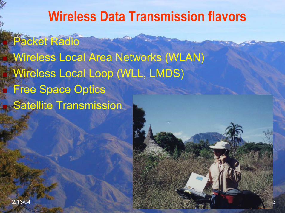
Wireless Data Transmission flavorsPacket RadioWireless Local Area Networks (WLAN)Wireless Local Loop (WLL, LMDS) Free Space OpticsSatellite Transmission
2/13/04 Pietrosemoli 4
Wi-Fi Technology Overview
Wireless networks where borne as LANs, but for developing countries’ applications they are more useful as MANs or even WANsThe enormous success of this technology has led to a dramatic price reduction of the radios, from $750 in 1992 to $30 in 2004, while transmission speed has increased up to 74 Mbps on the same 20 MHz channel
2/13/04 Pietrosemoli 5
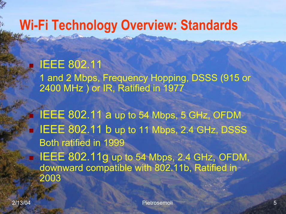
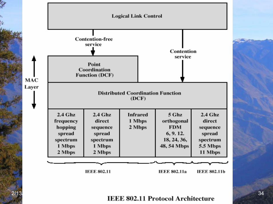
Wi-Fi Technology Overview: Standards
IEEE 802.111 and 2 Mbps, Frequency Hopping, DSSS (915 or 2400 MHz ) or IR, Ratified in 1977
IEEE 802.11 a up to 54 Mbps, 5 GHz, OFDMIEEE 802.11 b up to 11 Mbps, 2.4 GHz, DSSSBoth ratified in 1999IEEE 802.11g up to 54 Mbps, 2.4 GHz, OFDM, downward compatible with 802.11b, Ratified in 2003
2/13/04 Pietrosemoli 6
2/13/04 Pietrosemoli 7
2/13/04 Pietrosemoli 8
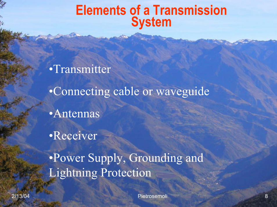
Elements of a Transmission System
•Transmitter
•Connecting cable or waveguide
•Antennas
•Receiver
•Power Supply, Grounding andLightning Protection
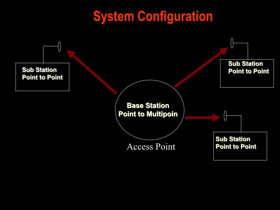
System Configuration
Base Base StationStationPoint to MultipoinPoint to Multipoin
Sub StationSub StationPoint to PointPoint to PointSub StationSub Station
Point to PointPoint to Point
Sub StationSub StationPoint to PointPoint to PointAccess Point
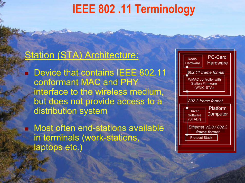
IEEE 802 .11 Terminology
Station (STA) Architecture:
Device that contains IEEE 802.11 conformant MAC and PHY interface to the wireless medium, but does not provide access to a distribution system
Most often end-stations available in terminals (work-stations, laptops etc.)
Platform ComputerPlatform
Computer
PC-Card HardwarePC-Card HardwareRadio
Hardware
Radio Hardware
WMAC controller withStation Firmware
(WNIC-STA)
WMAC controller withStation Firmware
(WNIC-STA)
Driver Software(STADr)
Driver Software(STADr)
802.11 frame format
802.3 frame format
Ethernet V2.0 / 802.3frame format
Protocol StackProtocol Stack
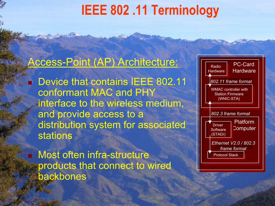
IEEE 802 .11 Terminology
Access-Point (AP) Architecture:
Device that contains IEEE 802.11 conformant MAC and PHY interface to the wireless medium, and provide access to a distribution system for associated stations
Most often infra-structure products that connect to wired backbones
Platform ComputerPlatform
Computer
PC-Card HardwarePC-Card HardwareRadio
Hardware
Radio Hardware
WMAC controller withStation Firmware
(WNIC-STA)
WMAC controller withStation Firmware
(WNIC-STA)
Driver Software(STADr)
Driver Software(STADr)
802.11 frame format
802.3 frame format
Ethernet V2.0 / 802.3frame format
Protocol StackProtocol Stack
IEEE 802 .11 Terminology
BSSA set of stations controlled by a single “Coordination Function” (=the logical function that determines when a station can transmit or receive)
Similar to a “cell” in pre IEEE terminology
A BSS can have an Access-Point (both in standalone networks and in building-wide configurations), or can run without and Access-Point (in standalone networks only)
Diameter of the cell is app. twice the coverage-distance between two wireless stations
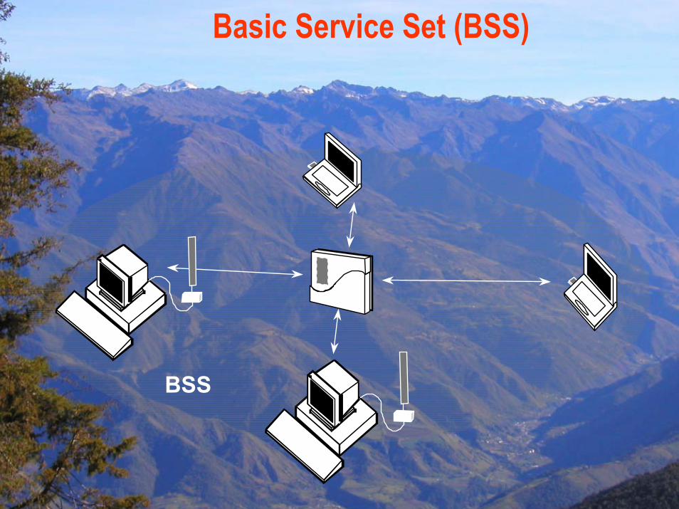
Basic Service Set (BSS)
BSS
IEEE 802 .11 Terminology
Independent Basic Service Set (IBSS):
A Basic Service Set (BSS) which forms a self-contained network in which no access to a Distribution System is available
A BSS without an Access-Point
One of the stations in the IBSS can be configured to “initiate” the network and assume the Coordination Function
Diameter of the cell determined by coverage distance between two wireless stations
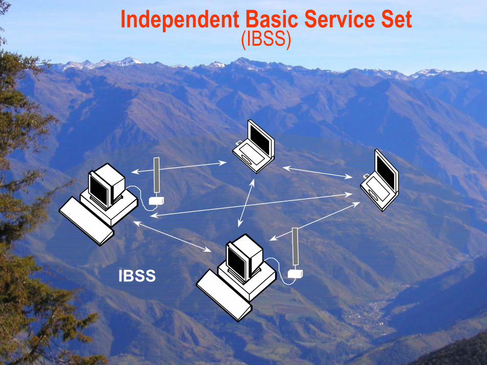
Independent Basic Service Set (IBSS)
IBSS
IEEE 802 .11 Terminology
Extended Service Set (ESS):A set of one or more Basic Service Sets interconnected by a Distribution System (DS)Traffic always flows via Access-Point
Distribution System (DS):A system to interconnect a set of Basic Service Sets
Integrated; A single Access-Point in a standalone networkWired; Using cable to interconnect the Access-PointsWireless; Using wireless to interconnect the Access-Points
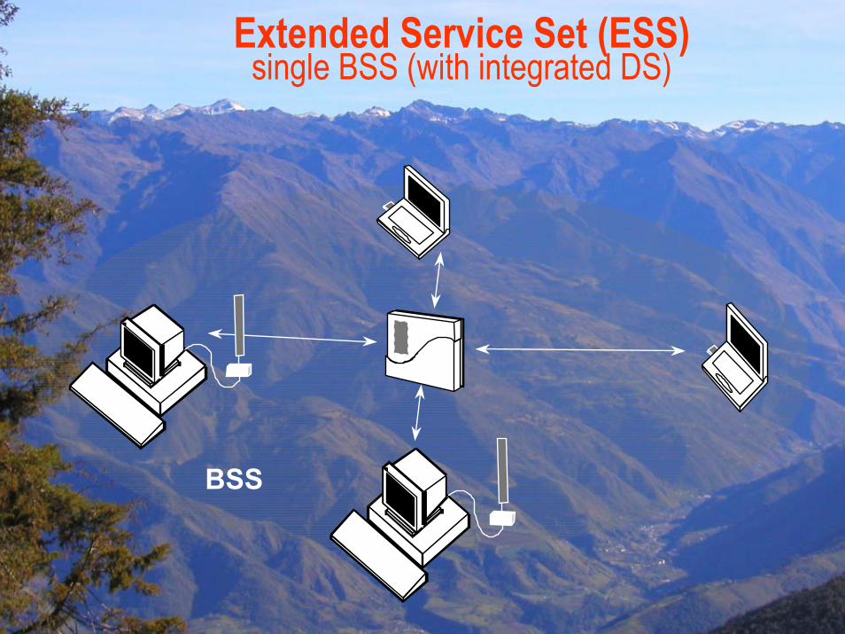
Extended Service Set (ESS) single BSS (with integrated DS)
BSS
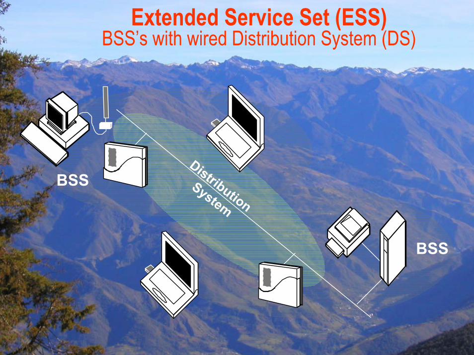
Extended Service Set (ESS) BSS’s with wired Distribution System (DS)
BSS
BSS
Distribution
System
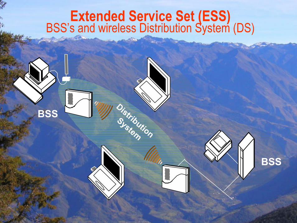
Extended Service Set (ESS) BSS’s and wireless Distribution System (DS)
BSS
BSS
Distribution
System
IEEE 802 .11 Terminology
Service Set Identifier (SSID):
“Network name”
32 octets long
One network (ESS or IBSS) has one SSID
IEEE 802 .11 Terminology
Basic Service Set Identifier (BSSID)
“cell identifier”
6 octets long (MAC address format)
One BSS has one SSID
Value of BSSID is the same as the MAC address of the radio in the Access-Point
MAC Management Frames
BeaconTimestamp, Beacon Interval, Capabilities, SSID, Supported Rates, parametersTraffic Indication Map
ProbeSSID, Capabilities, Supported Rates
Probe ResponseTimestamp, Beacon Interval, Capabilities, SSID, Supported Rates, parameterssame for Beacon except for TIM
MAC Management Frames (cont’d)
Association RequestCapability, Listen Interval, SSID, Supported Rates
Association ResponseCapability, Status Code, Station ID, Supported Rates
Re-association RequestCapability, Listen Interval, SSID, Supported Rates, Current AP Address
Re-association ResponseCapability, Status Code, Station ID, Supported Rates
2/13/04 Pietrosemoli 24
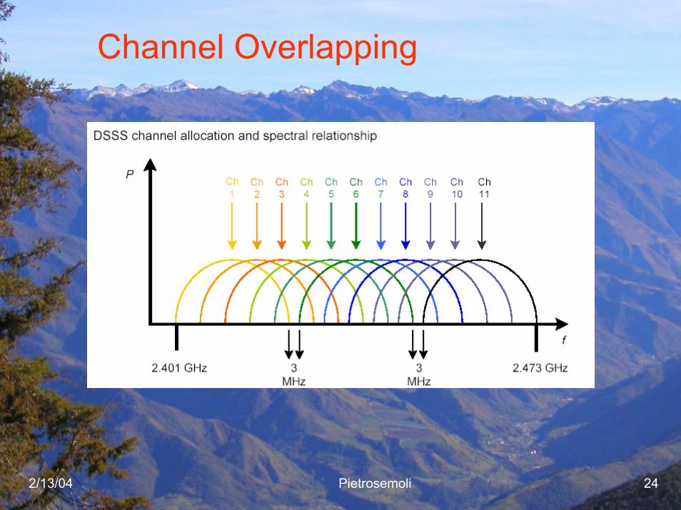
Channel Overlapping
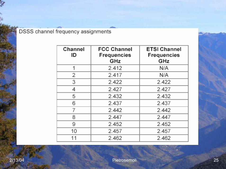
2/13/04 Pietrosemoli 25
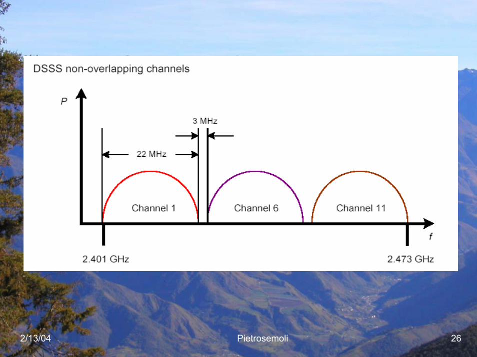
2/13/04 Pietrosemoli 26
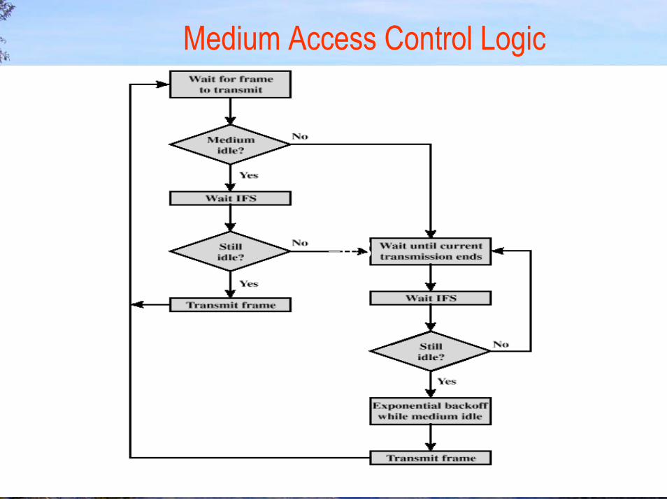
Medium Access Control Logic
–IFS
2/13/04 Pietrosemoli 28
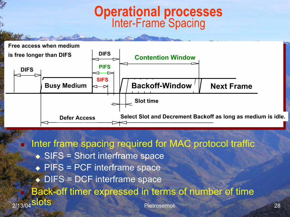
Operational processesInter-Frame Spacing
DIFS Contention Window
Slot time
Defer Access
Backoff-Window Next Frame
Select Slot and Decrement Backoff as long as medium is idle.
SIFS
PIFSDIFS
Free access when mediumis free longer than DIFS
Busy Medium
Inter frame spacing required for MAC protocol trafficSIFS = Short interframe spacePIFS = PCF interframe spaceDIFS = DCF interframe space
Back-off timer expressed in terms of number of time slots
2/13/04 Pietrosemoli 29
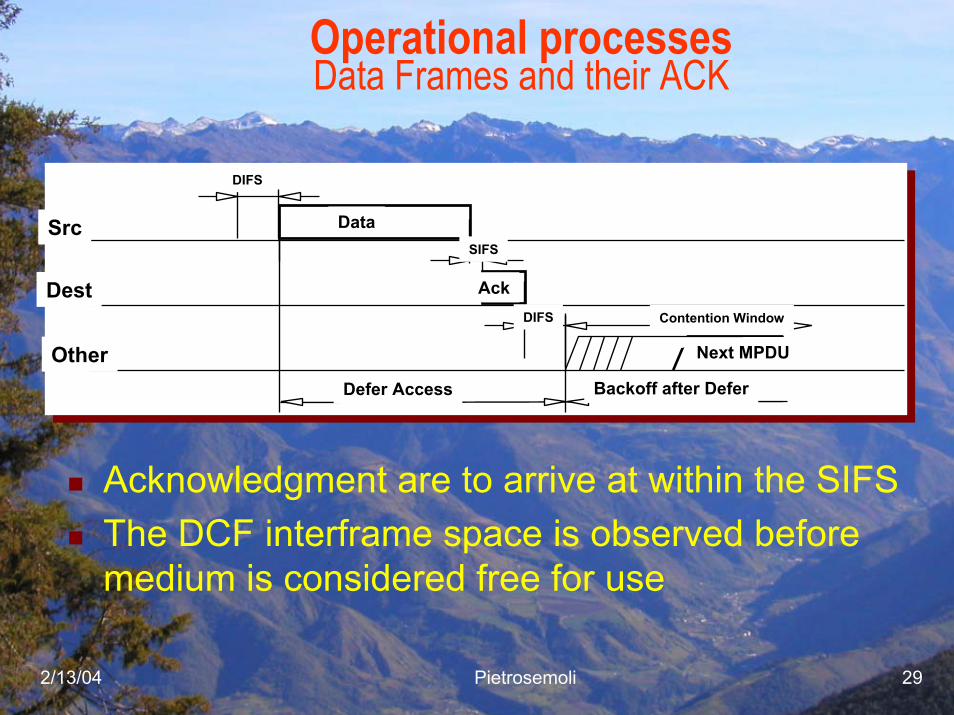
Operational processesData Frames and their ACK
Ack
Data
Next MPDU
Src
Dest
Other
Contention Window
Defer Access Backoff after Defer
DIFS
SIFS
DIFS
Acknowledgment are to arrive at within the SIFSThe DCF interframe space is observed before medium is considered free for use
2/13/04 Pietrosemoli 30
2/13/04 Pietrosemoli 31
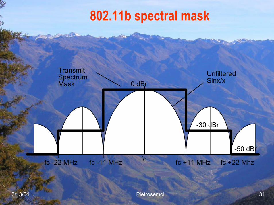
802.11b spectral mask
fcfc -11 MHzfc -22 MHz
Sinx/x
fc +11 MHz fc +22 Mhz
0 dBr
-30 dBr
-50 dBr
UnfilteredTransmitSpectrumMask
2/13/04 Pietrosemoli 32
Control Frames
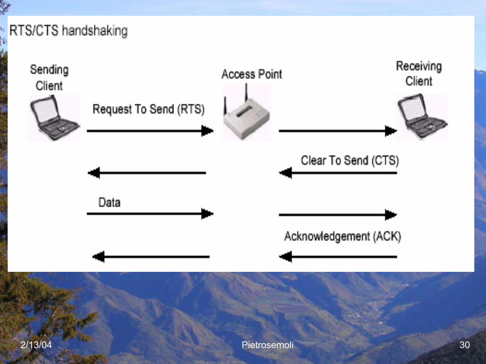
Request to send (RTS)Clear to send (CTS)Acknowledgement (ACK)Power-Save Poll (PS Poll)Contention-Free End (CF End)CF End + CF Ack

2/13/04 Pietrosemoli 33
Management Frames
Association request frameAssociation response frameReassociation request frameReassociation response frameProbe request frameProbe response frameBeacon frameATIM frameDisassociation frameAuthentication frameDeauthentication frame
2/13/04 Pietrosemoli 34
Access Control
2/13/04 Pietrosemoli 35
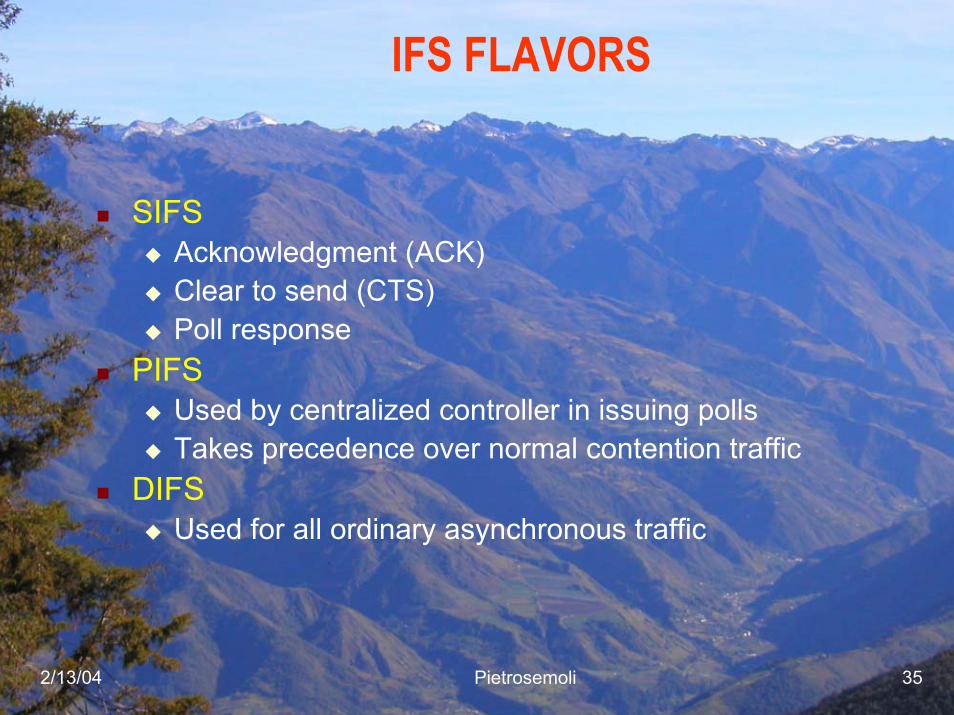
IFS FLAVORS
SIFSAcknowledgment (ACK)Clear to send (CTS)Poll response
PIFSUsed by centralized controller in issuing pollsTakes precedence over normal contention traffic
DIFSUsed for all ordinary asynchronous traffic
2/13/04 Pietrosemoli 36
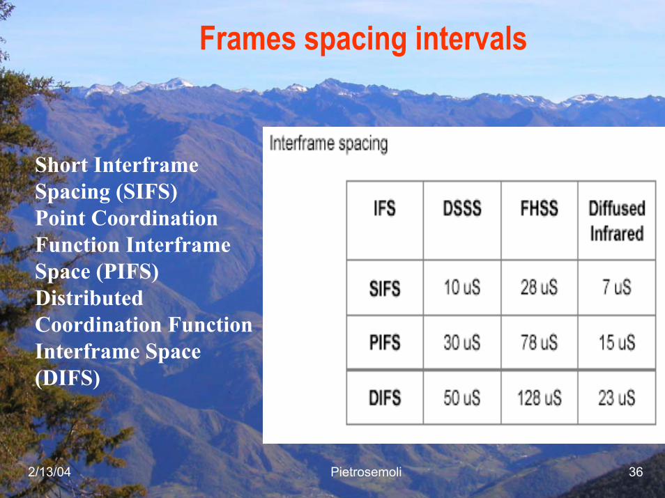
Frames spacing intervals
Short Interframe Spacing (SIFS)Point Coordination Function InterframeSpace (PIFS)Distributed Coordination Function Interframe Space (DIFS)
2/13/04 Pietrosemoli 37
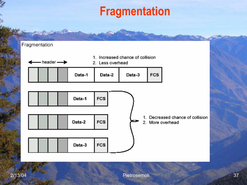
Fragmentation
2/13/04 Pietrosemoli 38
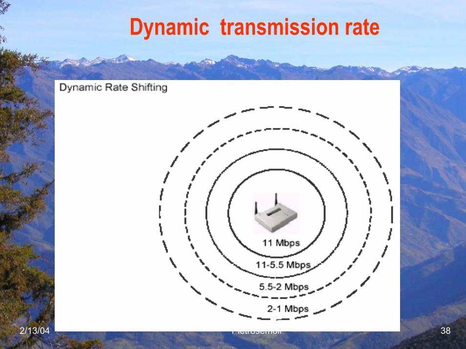
Dynamic transmission rate
2/13/04 Pietrosemoli 39
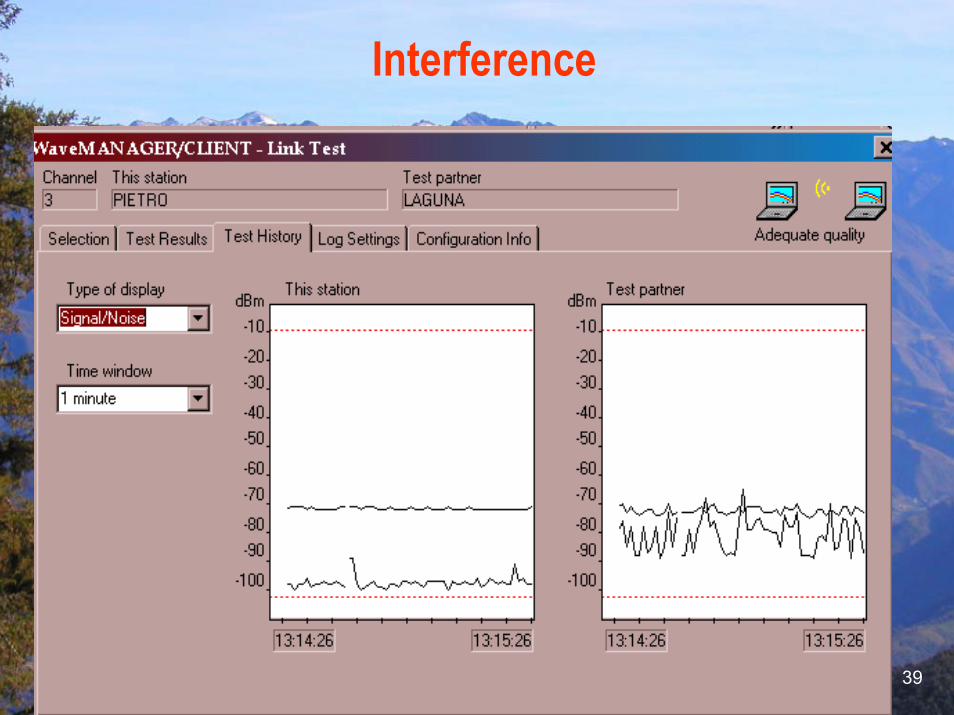
Interference
2/13/04 Pietrosemoli 40
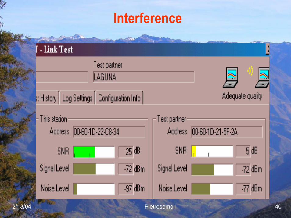
Interference
2/13/04 Pietrosemoli 41
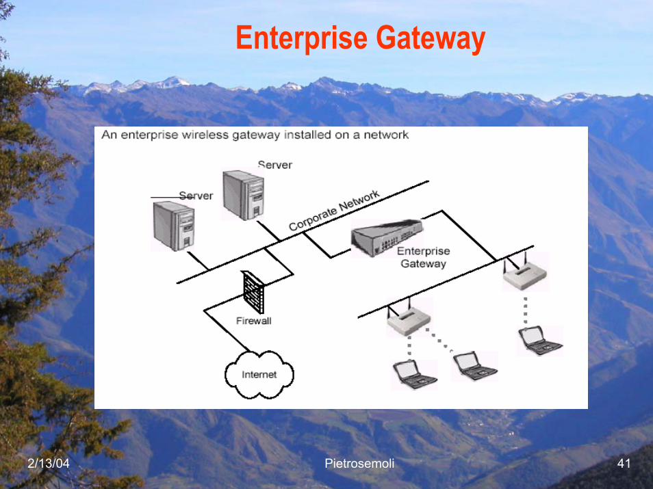
Enterprise Gateway
2/13/04 Pietrosemoli 42
Common options that most wirelessresidential gateways include are:
Point-to-Point Protocol over Ethernet (PPPoE)Network Address Translation (NAT)Port Address Translation (PAT)Ethernet switchingVirtual ServersPrint ServingFail-over routingVirtual Private Networks (VPNs)Dynamic Host Configuration Protocol (DHCP) Server and ClientConfigurable Firewall
2/13/04 Pietrosemoli 43
Enterprise Gateway Features
Enterprise wireless gateways do have features, such as Role-Based Access Control (RBAC), that are not found in any access points. RBAC allows an administrator to assign a certain level of wireless network access to a particular job position in the company. If the person doing that job is replaced, the new person automatically gains the same network rights as the replaced person. Having the ability to limit a wireless user's access to corporate resources, as part of the "role", can be a useful security feature.
2/13/04 Pietrosemoli 44
Enterprise Gateway Features
Class of service is typically supported, and an administrator can assign levels of service to a particular user or role. For example, a guest account might be able to use only 500 kbps on the wireless network whereas an administrator might be allowed 2 Mbps connectivity.
2/13/04 Pietrosemoli 45
Configuration and Managementof EG
Enterprise wireless gateways are installed in the main data path on the wired LAN segment just past the access point(s)
They are configured through console ports using telnet, internal HTTP or HTTPS servers, etc.
Centralized management of only a few devices is one big advantage of using enterprise wireless gateways. An administrator, from a single console, can easily manage a large wireless deployment using only a few central devices instead of a very large number of access points.
2/13/04 Pietrosemoli 46
Configuration and Managementof EWG
Enterprise wireless gateways are normally upgraded through use of TFTP in the same fashion as many switches and routers on the market today. Configuration backups can often be automated so that the administrator won't have to spend additional management time backing up or recovering from lost configuration files. Enterprise wireless gateways are mostly manufactured as rack-mountable 1U or 2U devices that can fit into your existing data center design.

2/13/04 Pietrosemoli 47
Power over distance
Gt Gr
Tx RxAt
Ar
Free Space Loss
Pt
PrdBm
km
2/13/04 Pietrosemoli 48
Power Limits
PtMP links have a central point of connection and two or more non-central connection points. PtMP links are typically configured in a star topology. The central connection point may or may not have an omnidirectionalantenna It is important to note that when an omnidirectional antenna is used, the FCC automatically considers the link a PtMP link.
Regarding the setup of a PtMP link, the FCC limits the EIRP to 4 Watts in both the 2.4 GHz ISM band and upper 5 GHz UNII band. The power limit set for the intentional radiator (the device transmitting the RF signal) in each of these bands is 1 Watt. If the transmitting wireless LAN devices are adjustable with respect to their output power, then the system can be customized to the needs of the user.
2/13/04 Pietrosemoli 49
Power Limits
Suppose a radio transmitting at 1 Watt (+30 dBm) is connected directly to a 12 dBi omnidirectional antenna. The total output power at the antenna is about 16 Watts, which is well above the 4 Watt limit. The FCC stipulates that for each 3 dBi above the antenna's initial 6 dBi of gain, the power at the intentional radiator must be reduced by 3 dB below the initial +30 dBm. For theexample, since the antenna gain is 12 dBi, the power at the intentional radiator must be reduced by 6 dB. This reduction will result in an intentional radiator power of +24 dBm (30 dBm – 6 dB), or 250 mW and an EIRP of 36 dBm (24 dBm + 12 dBi), or 4 Watts. The power at the intentional radiator must never be more than 1 Watt and the EIRP must never be above 4 Watts for a PtMPconnection.
2/13/04 Pietrosemoli 50
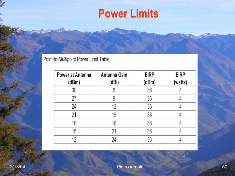
Power Limits

2/13/04 Pietrosemoli 51
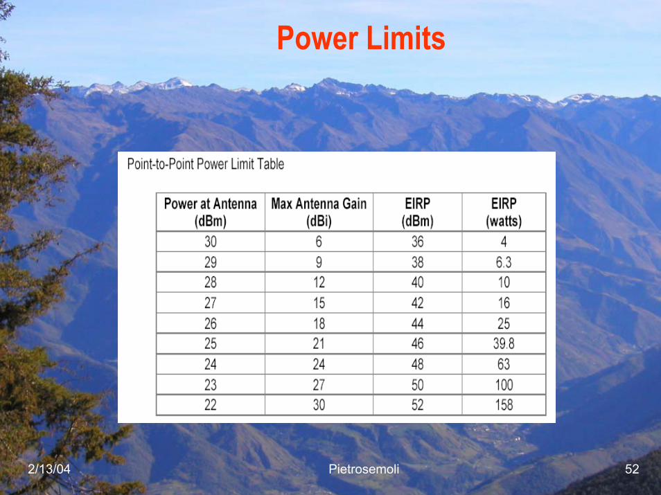
Power Limits
2/13/04 Pietrosemoli 52
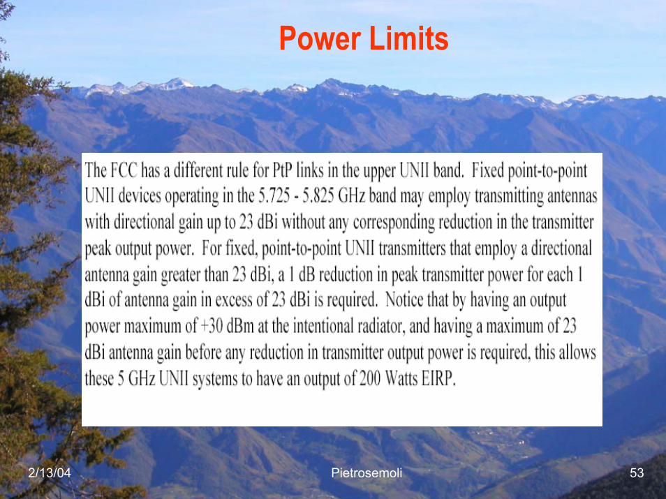
Power Limits
2/13/04 Pietrosemoli 53
Power Limits

2/13/04 Pietrosemoli 54
IEEE 802.11g
802.11g provides the same maximum speed of 802.11a, coupled with backwards compatibility for 802.11b devices. This backwards compatibility makes upgrading wireless LANs simple and inexpensive.IEEE 802.11g specifies operation in the 2.4 GHz ISM band. Toachieve the higher data rates found in 802.11a, 802.11g compliant devices utilize Orthogonal Frequency Division Multiplexing (OFDM) modulation technology. These devices can automatically switch to QPSK modulation in order to communicate with the slower 802.11b- and 802.11- compatible devices. There is no reason to keep purchasing 802.11b onlydevices nowadays, since for all practical purposes 802.11g is a superset of b, offering higher speed and some multipath inmunity
2/13/04 Pietrosemoli 55
Wireless Ethernet Compatibility Alliance
The Wireless Ethernet Compatibility Alliance (WECA) promotes and tests for wireless LAN interoperability of 802.11b devices and 802.11a devices. WECA’smission is to certify interoperability of Wi-Fi™ (IEEE 802.11) products and to promote Wi-Fi as the global wireless LAN standard across all market segments. As an administrator, you must resolve conflicts among wireless LAN devices that result from interference, incompatibility, or other problems.
2/13/04 Pietrosemoli 56
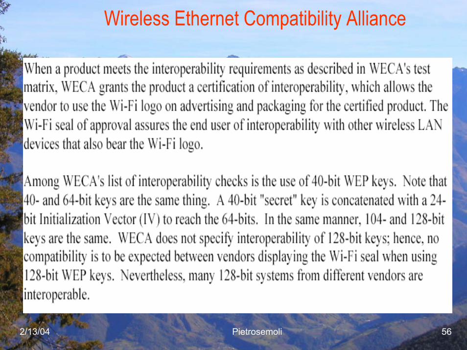
Wireless Ethernet Compatibility Alliance
2/13/04 Pietrosemoli 57
Supported Rates802.11b compliant device supports 11, 5.5, 2, & 1Mbps.802.11g can extend the capabilities to 54 Mbps as does802.11a.Some vendors offer “enhancements” over the standards that reach 108 Mbps, but this often increases the interference problem
2/13/04 Pietrosemoli 58
Passive ScanningPassive scanning is the process of listening for beacons on each channel for a specific period of time after the station is initialized. These beacons are sent by access points (infrastructure mode) or client stations (ad hoc mode), and the scanning station catalogs characteristics about the access points or stations based on these beacons. The station searching for a network listens for beacons until it hears a beacon listing the SSID of the network it wishes to join.The station then attempts to join the network through the access point that sent the beacon.
2/13/04 Pietrosemoli 59
Active Scanning
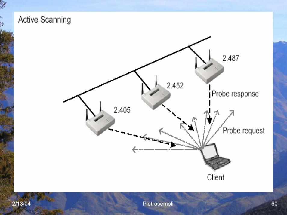
Active scanning involves the sending of a probe request frame from a wireless station.Stations send this probe frame when they are actively seeking a network to join. The probe frame will contain either the SSID of the network they wish to join or a broadcast SSID. If a probe request is sent specifying an SSID, then only access points that are servicing that SSID will respond with a probe response frame. If a probe request frame is sent with a broadcast SSID, then all access points within reach will respond with a probe response frame.The point of probing in this manner is to locate access points through which the station can attach to the network. Once an access point with the proper SSID is found, the station initiates the authentication and association steps of joining the network through that access point.
2/13/04 Pietrosemoli 60

2/13/04 Pietrosemoli 61
Questions?