wi-fi range demystified tutorial - university of cyprus and coverage xirrus… · type of antenna...
TRANSCRIPT
1
3
7 8
9
16 17
18
15
24
41
19
25
28
32
33
29
30
35
36
31
34
26
37
38
27
20 22
23
21
10
4 5
6
11
12
13
14
2
Wi-Fi Range DemystifiedTutorial
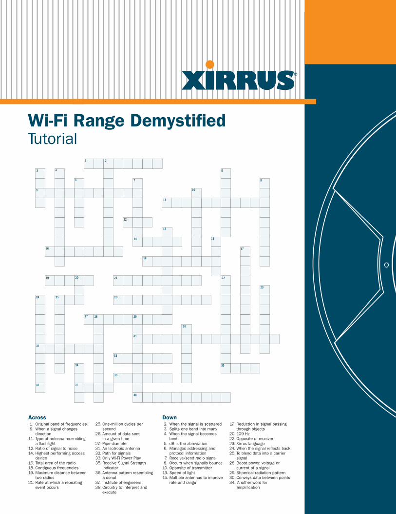
Across Down1. Originalbandoffrequencies9.Whenasignalchanges
direction11.Typeofantennaresembling
aflashlight12.Ratioofsignaltonoise14.Highestperformingaccess
device16.Totalareaoftheradio18.Contiguousfrequencies19.Maximumdistancebetween
tworadios21.Rateatwhicharepeating
eventoccurs
25.One-millioncyclespersecond
26.Amountofdatasentinagiventime
27. Pipediameter31.AnIsotropicantenna32.Pathforsignals33.OnlyWi-FiPowerPlay35.ReceiveSignalStrength
Indicator36.Antennapatternresembling
adonut37. Instituteofengineers38.Circuitrytointerpretand
execute
2.Whenthesignalisscattered3. Splitsonebandintomany4.Whenthesignalbecomes
bent5. dBistheabreviation6.Managesaddressingand
protocolinformation 7. Receive/sendradiosignal8. Occurswhensignallsbounce10.Oppositeoftransmitter13.Speedoflight15.Multipleantennastoimprove
rateandrange
17. Reductioninsignalpassingthroughobjects
20.109Hz22.Oppositeofreceiver23.Xirruslanguage24.Whenthesignalreflectsback25.Toblenddataintoacarrier
signal28.Boostpower,voltageor
currentofasignal29.Shpericalradiationpattern30.Conveysdatabetweenpoints34.Anotherwordfor
amplification

2 ©2008Xirrus,Inc.AllRightsReserved.
Wi-Fi Range Demystified
ContentsIntroduction............................................................................... 3
DefiningRangeandCoverage...................................................... 3
RangeBasics............................................................................. 4
AntennaDesign.......................................................................... 5
RangeandCoverage................................................................... 6
RangeLimitingFactors................................................................ 6
Multipath................................................................................... 7
Attenuation................................................................................ 8
HiddenNode.............................................................................. 8
Signal-to-NoiseRatio(SNR)......................................................... 9
RangeVersusCapacity.............................................................. 10
802.11nTechnology................................................................. 11
Recommendations.................................................................... 12
LeadingArchitecture................................................................. 13
AboutXirrus............................................................................. 13
©2008Xirrus,Inc.AllRightsReserved. 3
IntroductionDistancelimitationsanddataratesarefullyunderstoodwithwiredEthernetnetworksduetotheutilizationofspecifictransmitter/receiverstandardsandacontrolledmedia,thewire.However,thedistancelimitationsanddatarateswithWi-Finetworksaremoredifficulttocalculateduetovaryingdatarates,capacity,interference,etc.ThisdocumentwillwalkyouthroughsomebasicWi-Fiprinciplessuchasantennadesign,gain,pathloss,frameformat,multipath,etc.toenableyoutodeployahighperformingWi-Finetworkforyourorganization.
Defining Range and Coverage
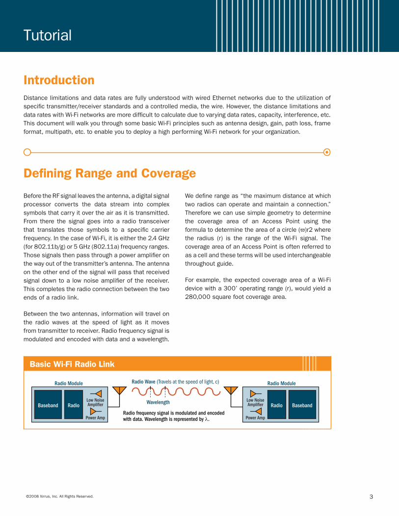
Basic Wi-Fi Radio Link
Baseband Radio
Radio Module Radio Wave (Travels at the speed of light, c)
BasebandRadio
Radio Module
Radio frequency signal is modulated and encoded with data. Wavelength is represented by λ.
WavelengthLow NoiseAmplifier
Power Amp
Low NoiseAmplifier
Power Amp
Wi-Fi Range Demystified Tutorial
BeforetheRFsignalleavestheantenna,adigitalsignalprocessor converts the data stream into complexsymbolsthatcarryitovertheairasitistransmitted.From there thesignalgoes intoa radio transceiverthat translates those symbols to a specific carrierfrequency.InthecaseofWi-Fi,itiseitherthe2.4GHz(for802.11b/g)or5GHz(802.11a)frequencyranges.Thosesignalsthenpassthroughapoweramplifieronthewayoutofthetransmitter’santenna.Theantennaontheotherendofthesignalwillpassthatreceivedsignaldowntoalownoiseamplifierofthereceiver.Thiscompletestheradioconnectionbetweenthetwoendsofaradiolink.
Betweenthetwoantennas,informationwilltravelonthe radio waves at the speed of light as itmovesfromtransmittertoreceiver.Radiofrequencysignalismodulatedandencodedwithdataandawavelength.
Wedefinerangeas“themaximumdistanceatwhichtworadioscanoperateandmaintainaconnection.”Thereforewecanusesimplegeometrytodeterminethe coverage area of an Access Point using theformulatodeterminetheareaofacircle(π)r2wherethe radius (r) is the range of theWi-Fi signal. ThecoverageareaofanAccessPointisoftenreferredtoasacellandthesetermswillbeusedinterchangeablethroughoutguide.
Forexample,theexpectedcoverageareaofaWi-Fidevicewitha300’operatingrange(r),wouldyielda280,000squarefootcoveragearea.
4 ©2008Xirrus,Inc.AllRightsReserved.
Link Formulas
RR LGPathLossGP TT −+−+=PR
Expected Free Space Signal Strength at the Receiver taking Transmit Power, Antenna Gain, Receiver Gain, Distance, and Frequency into account.
2
= GGPP RTTR 4 dπλ
Signal Strength (RSSI)
Gain and Transmit Power
~ 2dPP T
R
In Free Space, Power varies inversely with the square of the distance between two points.
RF Power Dissipation
Path Loss
Expected Signal Loss between a Transmitter and a Receiver using an appropriate Path Loss Exponent, n, for the environment. (See Path Loss Exponent chart).
4πλ
dPathLossdB n log1020 log +=
Link Budget
Expected Signal available in an interference-free environment for a given Transmit Power, Antenna Gain, Path Loss, and Receiver Loss. (See SNR).
PR—Power at the Receiver
PT—Power at the Transmitter
GT—Antenna Gain of the Transmitter
GR—Antenna Gain of the Receiver
λ—Wavelength (speed of light/frequency)
π—Ratio of a Circle’s Circumference to its Diameter, approximately 3.14
d—Distance in Meters
L R—Receiver Loss including Insertion Loss, Noise Figure, etc.
Signal Priorto Gain
Signal AfterGain
Ampl
itude
Range BasicsIt is important tounderstand that range isa functionofdatarateorsimplyput,thehigherthedatarate,theshortertherange.InordertounderstandwhatgoesintodeterminingtherangeofanAccessPoint,afewtermsneed tobedefinedandabasicunderstandingof themathematicsthatgoesintodeterminingthedistancebywhicharadiosignalwilltravelneedstobeprovided.
Inanopenenvironment,orwhatisreferredtoasFreeSpace, Power varies inversely with the square of thedistance between two points (the receiver and thetransmitter). The stronger the Transmit Power, thehigher thesignalstrengthorAmplitude.AntennaGainalsoincreasesAmplitudeandwillbefurtherdiscussedinasubsequentsectionofthischapter.
WhileGainandPowerincreasethedistanceawirelesssignalcantravel, theexpectedsignal loss (PathLoss)betweenthetransmitterandareceiverreducesit.PathLoss is the reduction in signal strength that a signalexperiencesasittravelsthroughtheairorthroughobjects
between the transmitter and receiver. The relativestrength of that signal at the receiver is measuredas the Received Signal Strength Indicator (RSSI).RSSIisnormallyexpressedindBmorasanumericalpercentage.Forclarificationpurposes,adB(Decibel)isameasureoftheratiobetweentwoquantitieswhiledBmisaDecibelwithrespecttomilliwattsofpower.Anoverall LinkBudget canbedefinedby taking intoaccountallthegainsandlossesofasignalasitmovesfromatransmittertoareceiver.
Range and Coverage
Range (Distance)
Coverage Area
r
2rarea π=Range—Maximum Distance between two radios for which a connection can be maintained.
Coverage—The total area in which all radios can maintain a connection to the AP.
Example: If the range of a cell is 300ft then the coverage area = 3.14 * (300)2 = 282,600sqft.
©2008Xirrus,Inc.AllRightsReserved. 5
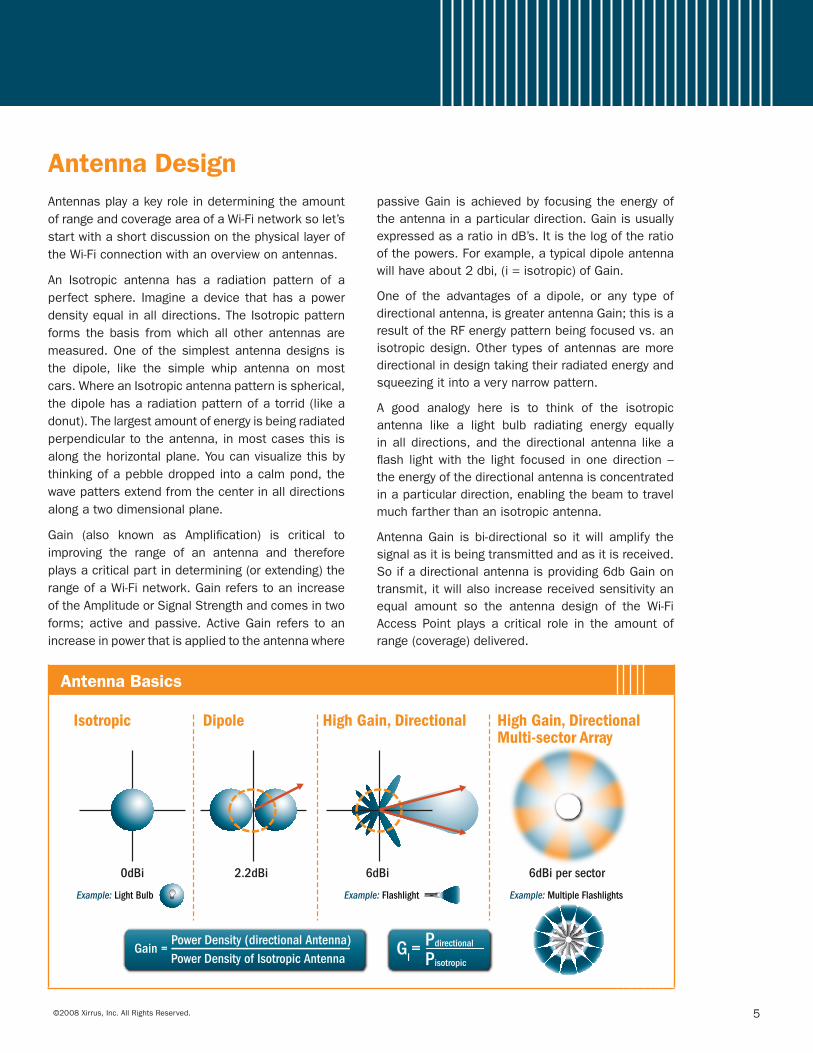
AntennasplayakeyroleindeterminingtheamountofrangeandcoverageareaofaWi-Finetworksolet’sstartwithashortdiscussiononthephysicallayeroftheWi-Ficonnectionwithanoverviewonantennas.
An Isotropic antenna has a radiation pattern of aperfectsphere. Imagineadevice thathasapowerdensityequalinalldirections.TheIsotropicpatternforms the basis fromwhich all other antennasaremeasured.Oneof thesimplestantennadesigns isthe dipole, like the simple whip antenna on mostcars.WhereanIsotropicantennapatternisspherical,thedipolehasaradiationpatternofatorrid(likeadonut).Thelargestamountofenergyisbeingradiatedperpendiculartotheantenna,inmostcasesthisisalongthehorizontalplane.Youcanvisualizethisbythinkingofapebbledroppedintoacalmpond,thewavepattersextendfromthecenterinalldirectionsalongatwodimensionalplane.
Gain (also known as Amplification) is critical toimproving the range of an antenna and thereforeplaysacriticalpartindetermining(orextending)therangeofaWi-Finetwork.GainreferstoanincreaseoftheAmplitudeorSignalStrengthandcomesintwoforms;activeandpassive.ActiveGain refers toanincreaseinpowerthatisappliedtotheantennawhere
passiveGain isachievedby focusing theenergyoftheantennainaparticulardirection.GainisusuallyexpressedasaratioindB’s.Itisthelogoftheratioofthepowers.Forexample,atypicaldipoleantennawillhaveabout2dbi,(i=isotropic)ofGain.
One of the advantages of a dipole, or any type ofdirectionalantenna,isgreaterantennaGain;thisisaresultoftheRFenergypatternbeingfocusedvs.anisotropicdesign.Other typesofantennasaremoredirectionalindesigntakingtheirradiatedenergyandsqueezingitintoaverynarrowpattern.
A good analogy here is to think of the isotropicantenna like a light bulb radiating energy equallyinall directions,and thedirectionalantenna likeaflash lightwith the light focused inonedirection–theenergyofthedirectionalantennaisconcentratedinaparticulardirection,enablingthebeamtotravelmuchfartherthananisotropicantenna.
AntennaGain is bi-directional so it will amplify thesignalasitisbeingtransmittedandasitisreceived.Soifadirectionalantennaisproviding6dbGainontransmit,itwillalsoincreasereceivedsensitivityanequal amount so the antenna design of the Wi-FiAccess Point plays a critical role in the amount ofrange(coverage)delivered.
Antenna Basics
Isotropic Dipole
0dBi 2.2dBi 6dBi 6dBi per sector
High Gain, Directional High Gain, DirectionalMulti-sector Array
Example: Light Bulb Example: Flashlight Example: Multiple Flashlights
Pisotropic
PdirectionalGain = Power Density (directional Antenna)
Power Density of Isotropic AntennaGl=
Antenna Design
6 ©2008Xirrus,Inc.AllRightsReserved.
Gain and antenna design can be used to increasetherangeofaWi-FiAccessPoint.Wealsomentionedthat physical and environmental factors will impactthatsignal,thissectionwillexamineseveralofthosefactors.
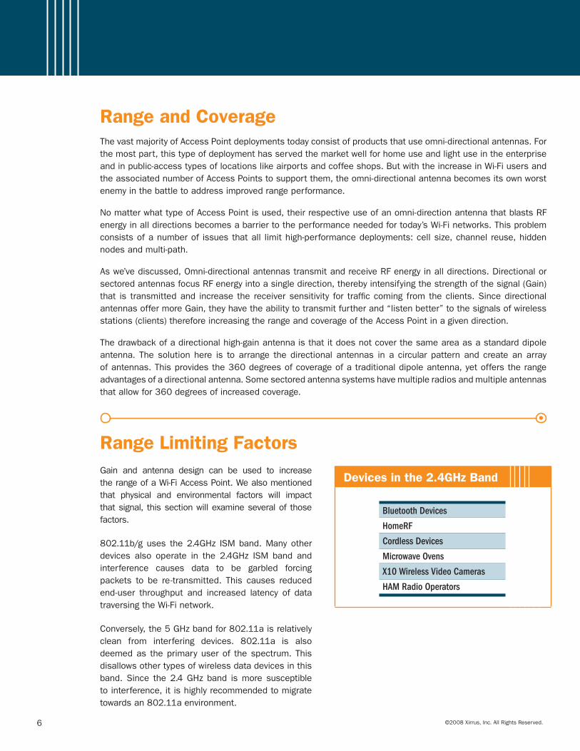
802.11b/guses the2.4GHz ISMband.Manyotherdevices also operate in the 2.4GHz ISM band andinterference causes data to be garbled forcingpackets to be re-transmitted. This causes reducedend-user throughput and increased latency of datatraversingtheWi-Finetwork.
Conversely,the5GHzbandfor802.11aisrelativelyclean from interfering devices. 802.11a is alsodeemedas theprimaryuserof thespectrum.Thisdisallowsothertypesofwirelessdatadevicesinthisband.Since the2.4GHzband ismore susceptibletointerference,itishighlyrecommendedtomigratetowardsan802.11aenvironment.
Devices in the 2.4GHz Band
Bluetooth Devices
HomeRF
Cordless Devices
Microwave Ovens
X10 Wireless Video Cameras
HAM Radio Operators
Range and CoverageThevastmajorityofAccessPointdeploymentstodayconsistofproductsthatuseomni-directionalantennas.Forthemostpart,thistypeofdeploymenthasservedthemarketwellforhomeuseandlightuseintheenterpriseandinpublic-accesstypesoflocationslikeairportsandcoffeeshops.ButwiththeincreaseinWi-FiusersandtheassociatednumberofAccessPointstosupportthem,theomni-directionalantennabecomesitsownworstenemyinthebattletoaddressimprovedrangeperformance.
NomatterwhattypeofAccessPointisused,theirrespectiveuseofanomni-directionantennathatblastsRFenergyinalldirectionsbecomesabarriertotheperformanceneededfortoday’sWi-Finetworks.Thisproblemconsistsofanumberof issuesthatall limithigh-performancedeployments:cellsize,channelreuse,hiddennodesandmulti-path.
Aswe’vediscussed,Omni-directionalantennastransmitandreceiveRFenergyinalldirections.DirectionalorsectoredantennasfocusRFenergyintoasingledirection,therebyintensifyingthestrengthofthesignal(Gain)that is transmittedand increase the receiversensitivity for trafficcoming fromtheclients.SincedirectionalantennasoffermoreGain,theyhavetheabilitytotransmitfurtherand“listenbetter”tothesignalsofwirelessstations(clients)thereforeincreasingtherangeandcoverageoftheAccessPointinagivendirection.
Thedrawbackofadirectionalhigh-gainantennaisthatitdoesnotcoverthesameareaasastandarddipoleantenna. Thesolutionhere is toarrange thedirectional antennas ina circular patternand createanarrayofantennas.Thisprovidesthe360degreesofcoverageofatraditionaldipoleantenna,yetofferstherangeadvantagesofadirectionalantenna.Somesectoredantennasystemshavemultipleradiosandmultipleantennasthatallowfor360degreesofincreasedcoverage.
Range Limiting Factors
©2008Xirrus,Inc.AllRightsReserved. 7
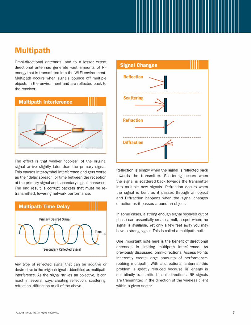
Omni-directional antennas, and to a lesser extentdirectional antennas generate vast amounts of RFenergythatistransmittedintotheWi-Fienvironment.Multipath occurs when signals bounce offmultipleobjectsintheenvironmentandarereflectedbacktothereceiver.
Multipath Interference
The effect is that weaker “copies” of the originalsignal arrive slightly later than the primary signal.Thiscausesinter-symbolinterferenceandgetsworseasthe“delayspread”,ortimebetweenthereceptionoftheprimarysignalandsecondarysignalincreases.Theend result is corrupt packets thatmust be re-transmitted,loweringnetworkperformance.
Multipath Time Delay
Secondary Reflected Signal
Time
Primary Desired Signal
Any type of reflected signal that can be additive ordestructivetotheoriginalsignalisidentifiedasmultipathinterference.Asthesignalstrikesanobjective,itcanreact in several ways creating reflection, scattering,refraction,diffractionoralloftheabove.
Signal Changes
Reflection
Scattering
Refraction
Diffraction
Reflectionissimplywhenthesignalisreflectedback
towards the transmitter. Scattering occurs when
thesignalisscatteredbacktowardsthetransmitter
into multiple new signals. Refraction occurs when
the signal is bent as it passes through an object
and Diffraction happens when the signal changes
directionasitpassesaroundanobject.
Insomecases,astrongenoughsignalreceivedoutof
phasecanessentiallycreateanull,aspotwhereno
signalisavailable.Yetonlyafewfeetawayyoumay
haveastrongsignal.Thisiscalledamultipathnull.
Oneimportantnotehereisthebenefitofdirectional
antennas in limiting multipath interference. As
previouslydiscussed,omni-directionalAccessPoints
inherently create large amounts of performance-
robbing multipath. With a directional antenna, this
problem is greatly reduced because RF energy is
not blindly transmitted in all directions. RF signals
aretransmittedinthedirectionofthewirelessclient
withinagivensector
Multipath
8 ©2008Xirrus,Inc.AllRightsReserved.
Attenuation
Hidden Node
RFsignalstrengthisreducedasitpassesthroughvariousmaterials.ThiseffectisreferredtoasAttenuation.Asmore Attenuation is applied to a signal, its effectiverangewillbereduced.TheamountofAttenuationwillvarygreatlybasedonthecompositionofthematerialtheRFsignalispassingthrough.
Attenuation Effects
Attenuation
The signal strength is reduced as it passes through an object.
Material Typical Attenuation (Loss) @ 5GHz
Cubical Wall 2dB
Drywall or Sheetrock 3dB
Brick Concrete or Block Wall 15dB
Elevator Shaft 10dB
Glass or Window 3dB
Concrete Floor 11dB
Cubicalwallsoffer relatively lowattenuation, in the2dbrange,whileconcreteandbrickwallswillcausehigher attenuation levels reducing the range of anAccess Point. It is extremely important to considernot just the type of obstruction, but how manyobstructionstheRFsignalmustpassthroughwhendesigningaWi-Finetwork.
Adirectionalantennaoffersanadvantageoveromni-directionalantennaswhenitcomestoattenuationastheyarebetterabletopenetratedifferentmaterialsthantraditionaldipoleantennas.
ThebottomlinetorememberisthatantennaselectionandthephysicalenvironmentofthefacilityhavethebiggestimpactonrangeandcoverageperformanceofanAccessPoint.However,itisimportanttonotethesearenottheonlyfactorsinvolved;the802.11specification in and of itself creates issues thatimpacttheoverallperformanceoftheWi-Finetwork.
The802.11specificationoperatesundera“collisionavoidance”schemawhereasclientsmustwaitforthemediumtobefreebeforemakingatransmission.ThisbasicpremisecreatesasituationwheretwoclientswithinaWi-Ficell(coverageareaoftheAccessPoint)arewithinrangeoftheAccessPoint,butoutofrangeofeachother.Awirelessstationononeedgeofacellmaynothearastationontheothersideofthecell.Because of this, wireless stations will not be ableto hear when the other is transmitting; incorrectlyassumingtheairisidleandbegintotransmititsownpackets. This will cause the two transmissions tocolliderequiringbothstationstore-transmitgreatlyreducingtheeffectivebandwidthwithinthecell.
A protection mechanism exists with in the 802.11standard calledCTS-RTS that can help address thisissuerequiringeachclienttoaskforpermissionfromtheAccessPointbeforetransmitting.Buttheuseofthisprotocolcreatesoverheadonthenetworkandwillreduceoverallperformanceby30%.Anothermethod
commonlyusedtoeliminateahiddennodeissueistoreducetherangeoftheAccessPointbydecreasingthetransmitpower.ByreducinganAccessPoint’srange,itincreasestheprobabilitythatallclientswithinthecellwillheareachother;butgreatlyincreasesthenumberofAccessPointsneededwithinthedeployment.
The use of a directional antenna over an omni-directional antennawill also eliminate the issue ofHiddenNodesbecauseallwirelessstations(clients)in a given RF sector are associated to the sameAccess Point; so they are geometrically within thesamesector.Sincetheclientsoperateinthesamesector,thehiddennodeproblemiseliminatedasallstations are able to hear each other and correctlydeterminewhentheairisbusyoridle.Thiseliminatesthe performance-robbing issues found with legacyomni-directional Access Points and the use of theCTS-RTSprotocol.ItalsohastheaddedbenefitofnotincreasingthenumberofAccessPointsorreducingtheirrespectivecoverageareas.
©2008Xirrus,Inc.AllRightsReserved. 9
Hidden Node Problem
Station 1 Station 2
Sectored Approach Eliminates Hidden Nodes
Note: Station 1 and Station 2 cannot hear each other’s transmissions in the omni-directional antenna example (above left) whereas stations can hear each other in the directional (sectored) antenna approach.
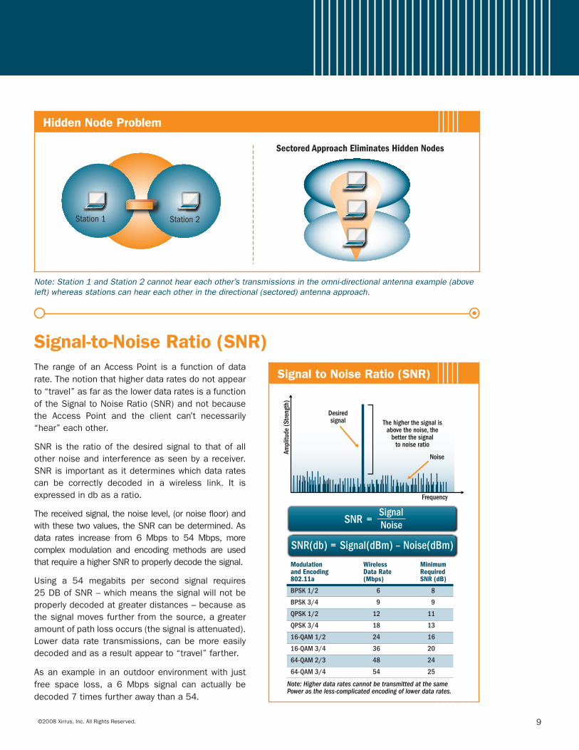
Signal-to-Noise Ratio (SNR)The rangeofanAccessPoint isa functionofdatarate.Thenotionthathigherdataratesdonotappearto“travel”asfarasthelowerdataratesisafunctionoftheSignaltoNoiseRatio(SNR)andnotbecausethe Access Point and the client can’t necessarily“hear”eachother.
SNR is the ratioof thedesiredsignal to thatofallothernoiseandinterferenceasseenbyareceiver.SNRisimportantasitdetermineswhichdataratescan be correctly decoded in a wireless link. It isexpressedindbasaratio.
Thereceivedsignal,thenoiselevel,(ornoisefloor)andwiththesetwovalues,theSNRcanbedetermined.Asdata rates increase from 6Mbps to 54Mbps, morecomplexmodulation and encodingmethods are usedthatrequireahigherSNRtoproperlydecodethesignal.
Using a 54 megabits per second signal requires25DBofSNR–whichmeansthesignalwillnotbeproperlydecodedatgreaterdistances–becauseasthesignalmovesfurtherfromthesource,agreateramountofpathlossoccurs(thesignalisattenuated).Lower data rate transmissions, can bemore easilydecodedandasaresultappearto“travel”farther.
Asanexample inanoutdoorenvironmentwith justfree space loss, a 6 Mbps signal can actually bedecoded7timesfurtherawaythana54.
Signal to Noise Ratio (SNR)
Desiredsignal
Noise
Ampl
itude
(Stre
ngth
)
Frequency
The higher the signal isabove the noise, the
better the signalto noise ratio
=SNR(db) Signal(dBm) – Noise(dBm)
SNRSignalNoise=
Note: Higher data rates cannot be transmitted at the same Power as the less-complicated encoding of lower data rates.
Modulation Wireless Minimumand Encoding Data Rate Required802.11a (Mbps) SNR (dB)
BPSK 1/2 6 8
BPSK 3/4 9 9
QPSK 1/2 12 11
QPSK 3/4 18 13
16-QAM 1/2 24 16
16-QAM 3/4 36 20
64-QAM 2/3 48 24
64-QAM 3/4 54 25
10 ©2008Xirrus,Inc.AllRightsReserved.
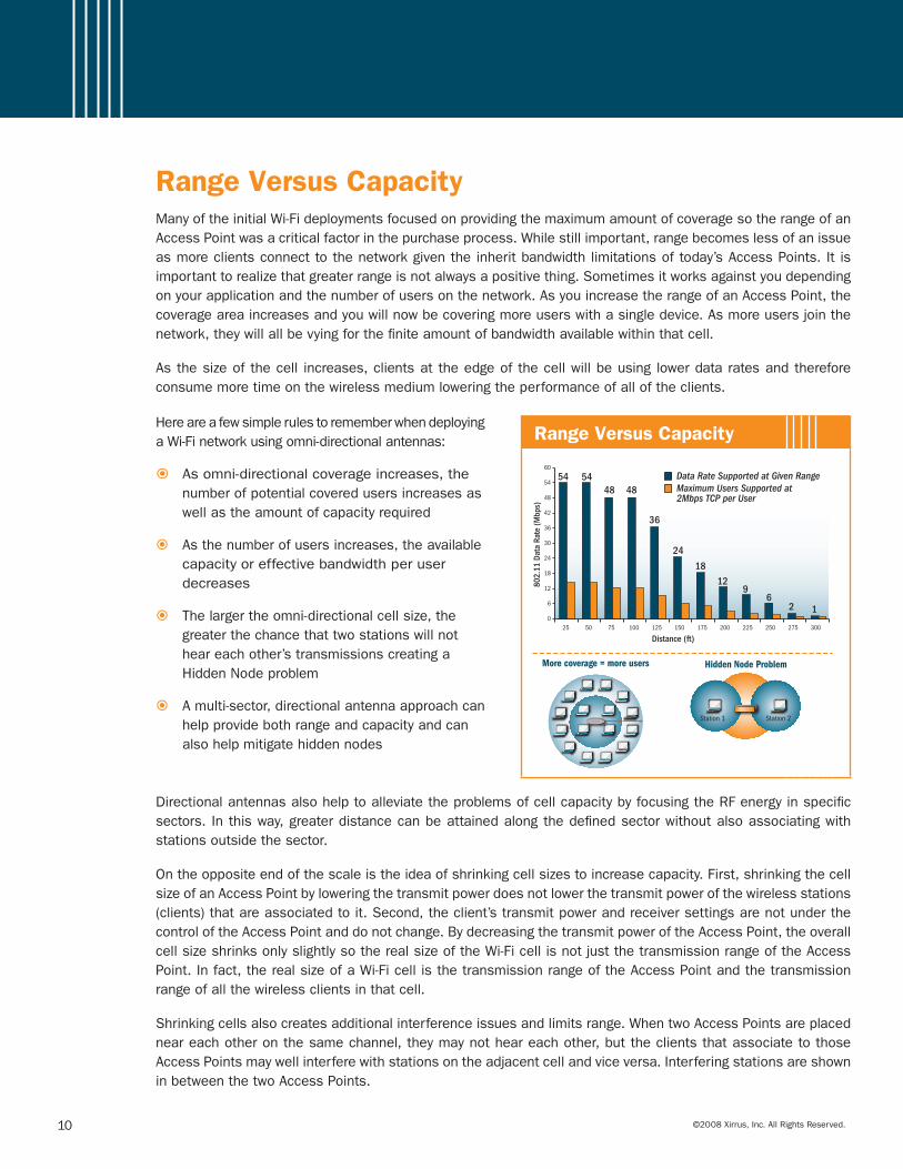
Range Versus CapacityManyoftheinitialWi-FideploymentsfocusedonprovidingthemaximumamountofcoveragesotherangeofanAccessPointwasacriticalfactorinthepurchaseprocess.Whilestillimportant,rangebecomeslessofanissueasmoreclientsconnecttothenetworkgiventheinheritbandwidthlimitationsoftoday’sAccessPoints.Itisimportanttorealizethatgreaterrangeisnotalwaysapositivething.Sometimesitworksagainstyoudependingonyourapplicationandthenumberofusersonthenetwork.AsyouincreasetherangeofanAccessPoint,thecoverageareaincreasesandyouwillnowbecoveringmoreuserswithasingledevice.Asmoreusersjointhenetwork,theywillallbevyingforthefiniteamountofbandwidthavailablewithinthatcell.
Asthesizeofthecell increases,clientsattheedgeofthecellwillbeusing lowerdataratesandthereforeconsumemoretimeonthewirelessmediumloweringtheperformanceofalloftheclients.
HereareafewsimplerulestorememberwhendeployingaWi-Finetworkusingomni-directionalantennas:
Asomni-directionalcoverageincreases,the�� numberofpotentialcoveredusersincreasesaswellastheamountofcapacityrequired
Asthenumberofusersincreases,theavailable��
capacityoreffectivebandwidthperuserdecreases
Thelargertheomni-directionalcellsize,the��
greaterthechancethattwostationswillnotheareachother’stransmissionscreatingaHiddenNodeproblem
Amulti-sector,directionalantennaapproachcan��
helpprovidebothrangeandcapacityandcanalsohelpmitigatehiddennodes
Range Versus Capacity
54
802.
11 D
ata
Rate
(Mbp
s)
Distance (ft)
60
54
48
42
36
30
24
18
12
6
025 50 75 100 125 150 175 200 225 250 275 300
5448
24
18
129
62 1
48
36
Station 1 Station 2
Hidden Node Problem
Data Rate Supported at Given RangeMaximum Users Supported at 2Mbps TCP per User
More coverage = more users
DirectionalantennasalsohelptoalleviatetheproblemsofcellcapacitybyfocusingtheRFenergyinspecificsectors. Inthisway,greaterdistancecanbeattainedalongthedefinedsectorwithoutalsoassociatingwithstationsoutsidethesector.
Ontheoppositeendofthescaleistheideaofshrinkingcellsizestoincreasecapacity.First,shrinkingthecellsizeofanAccessPointbyloweringthetransmitpowerdoesnotlowerthetransmitpowerofthewirelessstations(clients)thatareassociatedtoit.Second,theclient’stransmitpowerandreceiversettingsarenotunderthecontroloftheAccessPointanddonotchange.BydecreasingthetransmitpoweroftheAccessPoint,theoverallcellsizeshrinksonlyslightlysotherealsizeoftheWi-FicellisnotjustthetransmissionrangeoftheAccessPoint.Infact,therealsizeofaWi-FicellisthetransmissionrangeoftheAccessPointandthetransmissionrangeofallthewirelessclientsinthatcell.
Shrinkingcellsalsocreatesadditionalinterferenceissuesandlimitsrange.WhentwoAccessPointsareplacedneareachotheronthesamechannel,theymaynotheareachother,buttheclientsthatassociatetothoseAccessPointsmaywellinterferewithstationsontheadjacentcellandviceversa.InterferingstationsareshowninbetweenthetwoAccessPoints.
©2008Xirrus,Inc.AllRightsReserved. 11
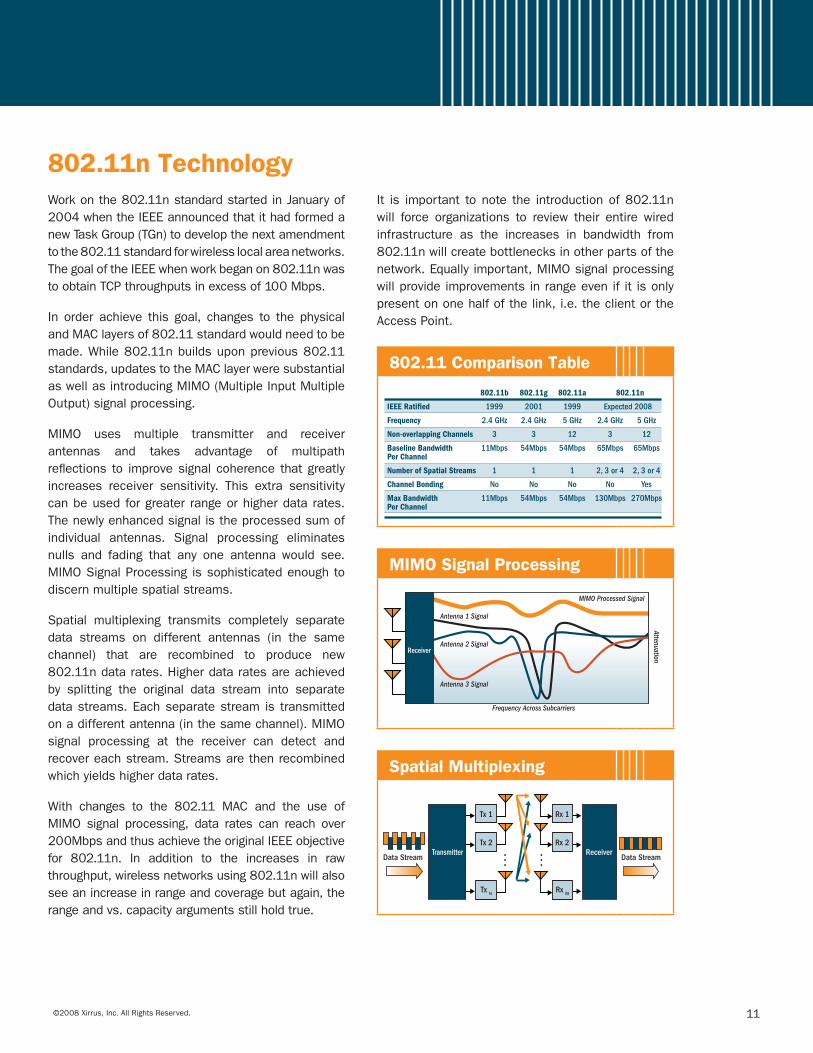
802.11n TechnologyWorkonthe802.11nstandardstartedinJanuaryof2004whentheIEEEannouncedthatithadformedanewTaskGroup(TGn)todevelopthenextamendmenttothe802.11standardforwirelesslocalareanetworks.ThegoaloftheIEEEwhenworkbeganon802.11nwastoobtainTCPthroughputsinexcessof100Mbps.
In order achieve this goal, changes to the physicalandMAClayersof802.11standardwouldneedtobemade.While802.11nbuildsuponprevious802.11standards,updatestotheMAClayerweresubstantialaswellasintroducingMIMO(MultipleInputMultipleOutput)signalprocessing.
MIMO uses multiple transmitter and receiverantennas and takes advantage of multipathreflections to improvesignalcoherence thatgreatlyincreases receiver sensitivity. This extra sensitivitycanbeusedforgreater rangeorhigherdatarates.Thenewlyenhancedsignalistheprocessedsumofindividual antennas. Signal processing eliminatesnulls and fading that any one antenna would see.MIMOSignalProcessingissophisticatedenoughtodiscernmultiplespatialstreams.
Spatial multiplexing transmits completely separatedata streams on different antennas (in the samechannel) that are recombined to produce new802.11ndatarates.Higherdataratesareachievedby splitting the original data stream into separatedatastreams.Eachseparatestream is transmittedonadifferentantenna(inthesamechannel).MIMOsignal processing at the receiver can detect andrecovereachstream.Streamsarethenrecombinedwhichyieldshigherdatarates.
With changes to the 802.11 MAC and the use ofMIMO signal processing, data rates can reach over200MbpsandthusachievetheoriginalIEEEobjectivefor 802.11n. In addition to the increases in rawthroughput,wirelessnetworksusing802.11nwillalsoseeanincreaseinrangeandcoveragebutagain,therangeandvs.capacityargumentsstillholdtrue.
It is important tonote the introductionof802.11nwill force organizations to review their entire wiredinfrastructure as the increases in bandwidth from802.11nwillcreatebottlenecksinotherpartsofthenetwork.Equallyimportant,MIMOsignalprocessingwillprovideimprovementsinrangeevenifitisonlypresentononehalfofthelink,i.e.theclientortheAccessPoint.
802.11 Comparison Table
MIMO Signal Processing
Frequency Across Subcarriers
Attenuation
Antenna 1 Signal
MIMO Processed Signal
Antenna 2 Signal
Antenna 3 Signal
Receiver
Spatial Multiplexing
M
Rx 1
Rx 2
Rx M
M
TransmitterData Stream Data Stream
Receiver
Tx 1
Tx 2
Tx N

12 ©2008Xirrus,Inc.AllRightsReserved.
RecommendationsToday’straditionalWi-Finetworkscannotkeeppacewiththetrajectoryofneededwirelesscapacityandcoverageforvoice,videoanddataapplicationsrunningoverWi-Fi.BycombiningaWirelessLANController/Switch,upto16IntegratedAccessPoints,GigabitEthernetSwitch,Wi-FiFirewallandMulti-SectorAntennaSystemintooneeasy-to-managedevice,Xirrusdeliverstheonlylongrange,highperformanceWi-Fiplatformintheindustrythatcaneffectivelyextendwirednetworkcapabilitiestowireless–withoutcompromise.
SettingupalargescaleWi-FinetworkisverydifferentthanitswiredcousinEthernet.Giventhefluidnatureofthewirelessmedium,coverageandperformancecanvarywidelydependingupontheenvironment.MostAccessPointsuseanomni-directionalantennatopropagatetheirsignalswhichlimittheirabilitytoadequatelydeliverincreasedrange.
TogetthebestrangeoutofyourWi-Fisystemareasfollows:
Higherdataantennasareobviouslybetterwith theexceptionbeingyoudon’tget the rangeofcoverage��
exceptwithanarrayofantennaslikeintheWi-FiArray.
SpendasmuchtimeevaluatingtheWi-Fisolutionsinyournotebooks,PDA’s,andotherclientstolookfor��
thebestreceivers,antennas,andradios.
Use802.11atoreducechannelinterferenceandtoallowformorecapacity.��
RememberthatrepositioningyourAPsmaymakedramaticchangeswhenyouhavemultipathissuesinside��
complicatedenvironments.
WhenmountingyourWi-Figear,thehigherthelocationandthemoreobstructionandsubstancesyouget��
outofthepathoftheradiowavesthebetteroffyouare.Mountingithigherisbetter.
Whenyou’replanningyoursolutionbecarefulnottocreatecellsthataresolargethatitcoverstoomany��
users,especially if they’reuserswithhighdemand.Rangeandcapacitymatters;becarefulwhenyou’redesigningyoursystem;usesimultaneouschannels;usingaXirrusArrayarchitecturethatcandelivertherangeandcapacityneededforfutureneeds.
©2008Xirrus,Inc.AllRightsReserved. 13
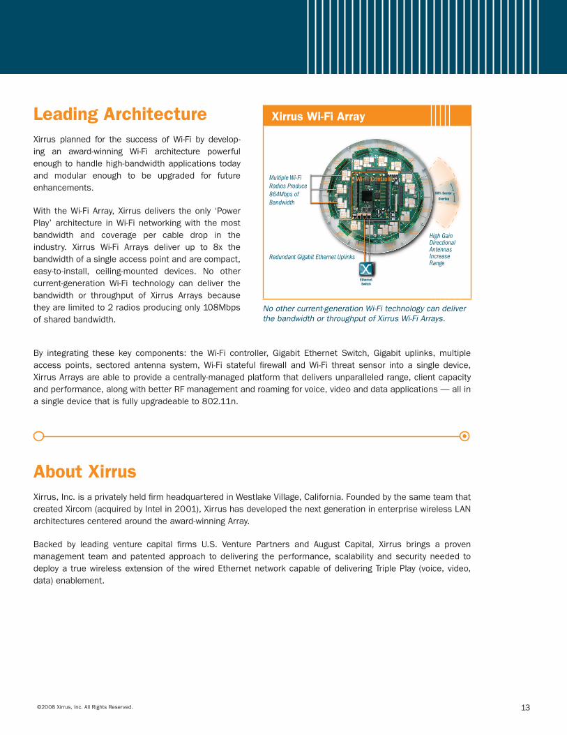
Leading ArchitectureXirrus planned for the success ofWi-Fi by develop-ing an award-winning Wi-Fi architecture powerfulenoughtohandlehigh-bandwidthapplicationstodayand modular enough to be upgraded for futureenhancements.
WiththeWi-FiArray,Xirrusdeliverstheonly ‘PowerPlay’architecture inWi-Finetworkingwith themostbandwidth and coverage per cable drop in theindustry. Xirrus Wi-Fi Arrays deliver up to 8x thebandwidthofasingleaccesspointandarecompact,easy-to-install, ceiling-mounted devices. No othercurrent-generation Wi-Fi technology can deliver thebandwidth or throughput of Xirrus Arrays becausetheyarelimitedto2radiosproducingonly108Mbpsofsharedbandwidth.
Xirrus Wi-Fi Array
Redundant Gigabit Ethernet Uplinks
Multiple Wi-Fi Radios Produce864Mbps of Bandwidth
High Gain Directional Antennas Increase Range
SectoredAntenna
SectoredAntenna
Wi-FiRadio
Wi-FiRadio
Wi-FiRadio
Wi-FiRadio
Wi-FiRadio
Wi-FiRadio
Wi-FiRadio
Wi-FiRadio
Wi-FiRadioWi-Fi
Radio
Wi-FiRadio
Wi-FiRadio
Wi-FiRadio
Wi-FiRadio
Wi-FiRadio
SectoredAntenna
SectoredAntenna
SectoredAntenna
SectoredAntenna
SectoredAntenna
SectoredAntenna
SectoredAntenna
SectoredAntenna
SectoredAntenna
Wi-Fi Controller
50% Sector Overlap
EthernetSwitch
SectoredAntenna
No other current-generation Wi-Fi technology can deliver the bandwidth or throughput of Xirrus Wi-Fi Arrays.
By integrating these key components: theWi-Fi controller, Gigabit Ethernet Switch, Gigabit uplinks,multipleaccesspoints, sectoredantennasystem,Wi-Fi stateful firewall andWi-Fi threatsensor intoasingledevice,XirrusArraysareabletoprovideacentrally-managedplatformthatdeliversunparalleledrange,clientcapacityandperformance,alongwithbetterRFmanagementandroamingforvoice,videoanddataapplications—allinasingledevicethatisfullyupgradeableto802.11n.
About XirrusXirrus,Inc.isaprivatelyheldfirmheadquarteredinWestlakeVillage,California.FoundedbythesameteamthatcreatedXircom(acquiredbyIntelin2001),XirrushasdevelopedthenextgenerationinenterprisewirelessLANarchitecturescenteredaroundtheaward-winningArray.
Backed by leading venture capital firms U.S. Venture Partners and August Capital, Xirrus brings a provenmanagement teamandpatentedapproach todelivering theperformance,scalabilityandsecurityneeded todeployatruewirelessextensionofthewiredEthernetnetworkcapableofdeliveringTriplePlay(voice,video,data)enablement.
Xirrus,Inc.
2101CorporateCenterDriveThousandOaks,CA91320,USA1.800.947.7871TollFreeintheUSA+1.805.262.1600Sales+1.805.262.1601Fax
Copyright©2008,Xirrus,Inc.AllRightsReserved.XirrusandtheXirruslogoaretrademarksofXirrus,Inc.Allothertrademarksbelongtotheirrespectiveowners.Protectedbypatent#USD526,973S.Otherpatentspending.
O
F
D
M
R
E
F
L
E
C
T
I
O
N
I
C
R
H
R
E
F
R
A
C
T
I
O
N
A
M
O
D
U
L
A
T
E
F
V
N
H
N
F
R
A
M
E
E
G
H
Z
N
G
A
I
N
B
A
R
E
B
E
E
A
C
A
A
M
P
L
I
F
I
E
R
S
C
A
T
T
E
R
I
N
G
N
E
E
I
E
F
T
D
X
D
B
O
R
H
W
I
I
A
A
N
T
E
N
N
A
E
R
I
S
O
T
R
O
P
I
C
N
RS
R
S
Q
O
D
M
R
O
O
D
R
P
U
U
T
N
U
L
N
D
W
A
V
E
L
E
N
G
T
H
I
S
E
T
I
Y
C
N
H
D
R
R
T
C
P
S
I
G
N
A
L
O
R
E
C
E
I
V
E
R
Y
U
R
L
C
U
T
E
L
T
M
I
M
O
C
E
D
E
C
I
B
E
L
T
R
A
N
S
I
T
T
E
R
R
O
I
S
N
A
T
T
E
N
U
A
T
I
O
N
S
A
N
I
M
U
L
T
I
P
A
T
H
X
I
R
R
I
LA
N
1
3
7 8
9
16 17
18
15
24
41
19
25
28
32
33
29
30
35
36
31
34
26
37
38
27
20 22
23
21
10
4 5
6
11
12
13
14
2
Wi-Fi Range Demystified Crossword Puzzle—Answer Key
Across Down1. Originalbandoffrequencies9.Whenasignalchangesdirection11.Typeofantennaresembling
aflashlight12.Ratioofsignaltonoise14.Highestperformingaccessdevice16.Totalareaoftheradio18.Contiguousfrequencies19.Maximumdistancebetween
tworadios21.Rateatwhicharepeatingevent
occurs25.One-millioncyclespersecond26.Amountofdatasentina
giventime27. Pipediameter31.AnIsotropicantenna32.Pathforsignals33.OnlyWi-FiPowerPlay35.ReceiveSignalStrengthIndicator36.Antennapatternresembling
adonut37. Instituteofengineers38.Circuitrytointerpretandexecute
2.Whenthesignalisscattered3. Splitsonebandintomany4.Whenthesignalbecomesbent5. dBistheabreviation6.Managesaddressingandprotocol
information 7. Receive/sendradiosignal8. Occurswhensignallsbounce10.Oppositeoftransmitter13.Speedoflight15.Multipleantennastoimproverate
andrange17. Reductioninsignalpassing
throughobjects20.109Hz22.Oppositeofreceiver23.Xirruslanguage24.Whenthesignalreflectsback25.Toblenddataintoacarriersignal28.Boostpower,voltageorcurrent
ofasignal29.Shpericalradiationpattern30.Conveysdatabetweenpoints34.Anotherwordforamplification