why golden rectangle is used so often by architects: a...
TRANSCRIPT

Alexandria Engineering Journal (2015) 54, 213–222
HO ST E D BY
Alexandria University
Alexandria Engineering Journal
www.elsevier.com/locate/aejwww.sciencedirect.com
ORIGINAL ARTICLE
Why golden rectangle is used so often by architects:
A mathematical approach
E-mail address: [email protected]
Peer review under responsibility of Faculty of Engineering, Alexandria
University.
http://dx.doi.org/10.1016/j.aej.2015.03.0121110-0168 ª 2015 Faculty of Engineering, Alexandria University. Production and hosting by Elsevier B.V.This is an open access article under the CC BY-NC-ND license (http://creativecommons.org/licenses/by-nc-nd/4.0/).
Krishnendra Shekhawat
Department of Mathematics, University of Geneva, Geneva, Switzerland
Received 3 August 2014; revised 19 January 2015; accepted 10 March 2015
Available online 3 April 2015
KEYWORDS
Algorithm;
Architectural design;
Connectivity;
Fibonacci rectangle;
Floor plan;
Golden rectangle
Abstract It is often found in the literature that many researchers have studied or documented the
use of golden rectangle or Fibonacci rectangle in architectural design. In this way, a lot of well-
known architects in the history, knowingly or unknowingly, have employed either the golden rec-
tangle or the Fibonacci rectangle in their works. Using some mathematical tools, this paper tried to
approach one of the properties of the golden rectangle (or the Fibonacci rectangle) and its signifi-
cance to architectural design, which could lead to state one hypothesis about why architects have
used them so often.
This work begins with an algorithm which constructs a Fibonacci rectangle and a golden rectan-
gle. Then adjacency among the squares (which are arranged inside them) is defined, by considering
each square as a room or an architectural space. At the end, using some tools of the graph theory, it
has been proved that they are one of the best arrangements of squares (or rectangles) inside a rec-
tangle, from the point of view of connectivity.ª 2015 Faculty of Engineering, Alexandria University. Production and hosting by Elsevier B.V. This is an
open access article under the CC BY-NC-ND license (http://creativecommons.org/licenses/by-nc-nd/4.0/).
1. Introduction
1.1. The golden ratio
The golden number is, in a sense, the most natural real number,since it can be written as:
u ¼ ½1�;
without reference to any numbering system. This is standard
abbreviation for the continued fraction expansion
u ¼ 1þ 1
1þ 11þ 1
1þ���
From this, it can be seen that u� 1 ¼ 1u, so that u is also equal
to 1þffiffi5p
2. The golden number is also the limit of the sequence of
convergents
pn=qnð Þ1n¼0 ¼1
1;2
1;3
2;5
3;8
5;13
8;21
13; . . .
� �;
which involves the successive Fibonacci numbers. This is notjust one more occurrence of the Fibonacci numbers; in fact,
a classical result (see Hardy & Wright [1], Chapter 10) is thatthe sequence of convergents is a sequence of best approx-imations to u by rational numbers, in a very specific sense.So, instead of saying that u ¼ 1:61803 . . ., which is meaningful

214 K. Shekhawat
only in the decimal system, it is better to consider u as a
sequence of convergents
u ¼ 1
1;2
1;3
2;5
3;8
5;13
8;21
13;34
21;55
34;89
55; . . .
� �:
1.2. Relation between the golden rectangle and the Fibonaccirectangle
The golden rectangle is a rectangle whose ratio of width over
height is equal to u with a geometric property as follows:One can remove a square with side length one from a rec-
tangle of sides 1� u and obtain a new rectangle, with sides1u� 1, which is similar to the original one. Hence, the construc-
tion can be repeated (see Walser [2], Chapter 3). The goldenrectangle and logarithmic spiral are shown in Fig. 1. The loga-
rithmic spiral is centered at the point O which is the intersec-tion of the two diagonals BD and CE1. Its radius r isreduced by a factor u each time the angle h is decreased by
p=2.The golden rectangle is considered as one of the shape for
representing u in two dimensions (refer [3]). Because of this,
u and golden rectangle have same properties as well as themost visually pleasing constructions.
In a Fibonacci sequence, each of its term is obtained from
the sum of the two preceding terms i.e. Fnþ1 ¼ Fn þ Fn�1 forn > 1 where F0 ¼ F1 ¼ 1. Here each Fn is called Fibonaccinumber. A Fibonacci rectangle is a rectangle with side lengthsx and y such that either x=y or y=x is equal to Fnþ1=Fn for some
non-negative integer n. Naturally, one can construct such arectangle by successively introducing squares of side lengthsF0;F1;F2; . . . as shown in Fig. 5. It can be easily seen that
the ratio of two successive Fibonacci numbers ðFnþ1=FnÞapproaches u.
If only the arrangement of squares is considered, the two
Figures, golden rectangle and Fibonacci rectangle, look simi-lar, whereas, geometrically it is far more convenient to usethe Fibonacci rectangle in comparison with the golden rectan-gle, because, it is comparatively easy to draw a rectangle with
integer dimensions (say 5� 8) than a rectangle having rationalor irrational dimensions respectively.
1.3. Golden rectangle, Fibonacci rectangle and architecture
The u or golden rectangle has been found in the natural worldthrough human proportions and through growth patterns of
many living plants, animals, and insects. Basically, it has been
Figure 1 The golden rectangle and logarithmic spiral.
always considered that u is the most pleasing proportion tohuman eyes [4,5]. The presence of u in the design of thePyramids represents that the Egyptians were aware of the
number. A Greek sculptor and mathematician, Phidias(490–430 BC), was first to study and apply Phi, to the designof sculptures for the Parthenon (example of Doric architecture,
the main temple of the goddess Athena) [5,6].Around 1200 AD, Leonardo Fibonacci (1170–1250 AD),
an Italian born mathematician found u in a numerical series
(known as Fibonacci series) and named it divine proportion,due to which, Fibonacci series can be used to construct thegolden rectangle [3]. The design of Notre Dame in Paris, whichwas built in between 1163 and 1250, appears to have golden
rectangle in number of its key proportions. Likewise, theRenaissance artists used the golden rectangle in their variouspaintings and sculptures to achieve balance and esthetic beauty
[7].Also, u is been favorite to many key architects in history,
such as, Palladio, Le Corbusier, Pacioli, and Leonardo Da
Vinci. Palladio’s Villa La Rotonda is designed using u, seeFigs. 12–14 (for details of Palladio’s work, refer [8], IQuattro Libri dell’Architettura). Le Corbusier himself wrote
Modulor I and II (refer [9]) where for instance he displayedthe composition and drawing of his ‘Modulor’ figure by usingthe golden ratio. As a sculptor and applied mathematician,George Hart [10] delves the work of Pacioli and Leonardo
Da Vinci given in the book De Divina Proportione.In addition, many recent publications discussed the golden
ratio and architectural designs that exist at the different
moments of history. In 1986, Burckhardt [11] studied the pres-ence of golden rectangle in a house of 1871 in Basel. In 2000,Mark Reynolds [12] presented the use of the golden section in
generating the geometry of Pazzi Chapel of Santa Croce inFlorence. In 2013, Fernandez-Llebrez and Fran [13] discussedthe presence of the golden section and the Fibonacci sequence
in the compositional scheme of the Roman Catholic ChurchPastoor Van Ars, built by Aldo van Eyck in The Hague in1968.
It is hard to find many publications showing the presence of
Fibonacci sequence in the geometrical composition of architec-tural design; two of them are mentioned as follows:
Bartoli [14] discussed the case of Palazzo della Signoria,
where the Fibonacci rectangle has been found (see Figs. 15and 16). In the same way, Park and Lee [15] published theunderlying design of the Braxton-Shore house by Rudolph
Schindler, which is based on the Fibonacci sequence.From the work of many authors and researchers, it can be
easily seen that many buildings and architectural designs (fromancient to contemporary time) have been developed using the
golden rectangle or the Fibonacci rectangle, but it is difficult tofind a mathematical or logical reason behind it. That is why,this paper tried to provide a possible mathematical explanation
to this question in terms of adjacency among the rooms of anarchitectural design.
2. Rectangular arrangements and connectivity
2.1. Rectangular arrangements
A rectangular arrangement is defined as an arrangement ofsub-rectangles inside a bigger rectangle where:
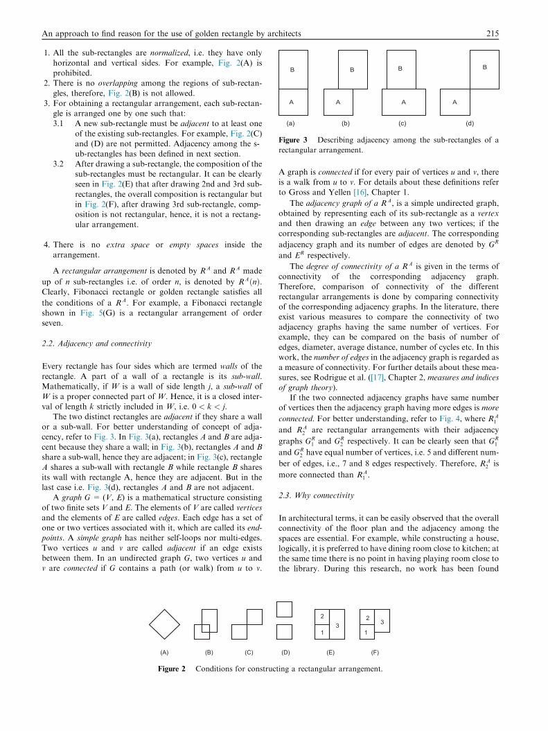
Figure 3 Describing adjacency among the sub-rectangles of a
rectangular arrangement.
An approach to find reason for the use of golden rectangle by architects 215
1. All the sub-rectangles are normalized, i.e. they have only
horizontal and vertical sides. For example, Fig. 2(A) isprohibited.
2. There is no overlapping among the regions of sub-rectan-
gles, therefore, Fig. 2(B) is not allowed.3. For obtaining a rectangular arrangement, each sub-rectan-
gle is arranged one by one such that:3.1 A new sub-rectangle must be adjacent to at least one
of the existing sub-rectangles. For example, Fig. 2(C)and (D) are not permitted. Adjacency among the s-ub-rectangles has been defined in next section.
3.2 After drawing a sub-rectangle, the composition of thesub-rectangles must be rectangular. It can be clearlyseen in Fig. 2(E) that after drawing 2nd and 3rd sub-
rectangles, the overall composition is rectangular butin Fig. 2(F), after drawing 3rd sub-rectangle, comp-osition is not rectangular, hence, it is not a rectang-ular arrangement.
4. There is no extra space or empty spaces inside thearrangement.
A rectangular arrangement is denoted by RA and RA made
up of n sub-rectangles i.e. of order n, is denoted by RAðnÞ.Clearly, Fibonacci rectangle or golden rectangle satisfies all
the conditions of a RA. For example, a Fibonacci rectangleshown in Fig. 5(G) is a rectangular arrangement of orderseven.
2.2. Adjacency and connectivity
Every rectangle has four sides which are termed walls of the
rectangle. A part of a wall of a rectangle is its sub-wall.Mathematically, if W is a wall of side length j, a sub-wall ofW is a proper connected part of W. Hence, it is a closed inter-val of length k strictly included in W, i.e. 0 < k < j.
The two distinct rectangles are adjacent if they share a wallor a sub-wall. For better understanding of concept of adja-cency, refer to Fig. 3. In Fig. 3(a), rectangles A and B are adja-
cent because they share a wall; in Fig. 3(b), rectangles A and Bshare a sub-wall, hence they are adjacent; in Fig. 3(c), rectangleA shares a sub-wall with rectangle B while rectangle B shares
its wall with rectangle A, hence they are adjacent. But in thelast case i.e. Fig. 3(d), rectangles A and B are not adjacent.
A graph G = (V, E) is a mathematical structure consisting
of two finite sets V and E. The elements of V are called verticesand the elements of E are called edges. Each edge has a set ofone or two vertices associated with it, which are called its end-points. A simple graph has neither self-loops nor multi-edges.
Two vertices u and v are called adjacent if an edge existsbetween them. In an undirected graph G, two vertices u andv are connected if G contains a path (or walk) from u to v.
Figure 2 Conditions for construct
A graph is connected if for every pair of vertices u and v, thereis a walk from u to v. For details about these definitions refer
to Gross and Yellen [16], Chapter 1.
The adjacency graph of a RA, is a simple undirected graph,
obtained by representing each of its sub-rectangle as a vertexand then drawing an edge between any two vertices; if thecorresponding sub-rectangles are adjacent. The corresponding
adjacency graph and its number of edges are denoted by GR
and ER respectively.
The degree of connectivity of a RA is given in the terms of
connectivity of the corresponding adjacency graph.Therefore, comparison of connectivity of the differentrectangular arrangements is done by comparing connectivityof the corresponding adjacency graphs. In the literature, there
exist various measures to compare the connectivity of twoadjacency graphs having the same number of vertices. Forexample, they can be compared on the basis of number of
edges, diameter, average distance, number of cycles etc. In thiswork, the number of edges in the adjacency graph is regarded asa measure of connectivity. For further details about these mea-
sures, see Rodrigue et al. ([17], Chapter 2, measures and indicesof graph theory).
If the two connected adjacency graphs have same numberof vertices then the adjacency graph having more edges is more
connected. For better understanding, refer to Fig. 4, where RA1
and RA2 are rectangular arrangements with their adjacency
graphs GR1 and GR
2 respectively. It can be clearly seen that GR1
and GR2 have equal number of vertices, i.e. 5 and different num-
ber of edges, i.e., 7 and 8 edges respectively. Therefore, RA2 is
more connected than RA1 .
2.3. Why connectivity
In architectural terms, it can be easily observed that the overallconnectivity of the floor plan and the adjacency among thespaces are essential. For example, while constructing a house,
logically, it is preferred to have dining room close to kitchen; atthe same time there is no point in having playing room close tothe library. During this research, no work has been found
ing a rectangular arrangement.

Figure 4 Comparing the connectivity of two different rectangular arrangements.
216 K. Shekhawat
where connectivity has been considered for the design of a
floor plan. But, in the literature, it can be seen that withoutmentioning connectivity, architects have used this concept insome form or other. For example, Roth [18] has consideredadjacency among the cells for constructing a rectangular floor
plan. In the coming sections, it would be interesting to see thatthis concept of adjacency and connectivity would help in pro-viding a mathematical answer, to the question of using the
Fibonacci rectangle and golden rectangle so often byarchitects.
3. Construction of a Fibonacci rectangle
Lemmas 1 and 2 are well known results that already exist inthe literature in same or other form.
Lemma 1. The process of cutting off a square can be done bystarting from any Fibonacci rectangle. The ratios of width overheight for the successive residual rectangles run through allquotients of the form Fn=Fn�1;Fn�1=Fn�2, etc., until the last
square has been reached, which is of size 1. Then the residualrectangle is a square of side length F1 ¼ F0 ¼ 1.
Proof. Removing a square of side length Fn from a rectangle
with sides Fnþ1 � Fn yields a rectangle with sidesFn � Fn�1,since Fnþ1 � Fn ¼ Fn�1. And this process can berepeated until a rectangle with sides F2 � F1 ¼ 2� 1 isobtained. The next square to be cut off has side length
F1 ¼ 1 and the residual rectangle is a square of side length 1.For further details, refer to Fig. 5 from (G) to (A) and seeWalser [1], page 39. h
Figure 5 A sequence of Fibonacci rectangles, corres
Lemma 2. One can construct a sequence of Fibonacci rectanglesby reversing the process described in Lemma 1. Starting fromtwo unit squares one above another, one first adjoins a square
of side length 2 to their right, so as to obtain a Fibonacci rectan-gle with sides F3 � F2. Then one adjoins a square of side lengthF3 below, so as to obtain a Fibonacci rectangle with sides
F5 � F3, etc. following a clockwise movement.
Proof. The possibility of this construction of a sequence ofFibonacci rectangles follows from the relationFnþ1 ¼ Fn þ Fn�1. For details refer to Fig. 5 from (A) to (G),
where a sequence of Fibonacci rectangles is displayed. h
A Fibonacci rectangle having n squares is called a
Fibonacci rectangle of order n and it is denoted by FRðnÞ.The golden rectangle of order n is denoted by GoR. The loga-
rithmic spiral can be replaced by its natural approximation byquarter circles in the successive squares appearing in this con-struction. It is termed Fibonacci spiral. For example, the
Fibonacci spiral is shown in Fig. 5(G).
4. Maximum number of edges in the adjacency graph
of a rectangular arrangement
4.1. Adjacent sides and adjacent numbers
This section provides an important result, which will be furtherused to prove that both the golden rectangle and the Fibonacci
rectangle are best connected.
It is obvious to see that a RA consists of sub-rectangles but,
it is also a rectangle having four sides. Each of its side is termed
ponding adjacency graphs and a Fibonacci spiral.

An approach to find reason for the use of golden rectangle by architects 217
adjacent side. For example, in Fig. 6, the drawn RA has four
adjacent sides which are illustrated in bold and are called left,upper, right and lower adjacent sides. Also, each adjacent sideis made up of different number of walls of the sub-rectangles.
These numbers are termed adjacent numbers. The adjacentnumbers, associated with left, upper, right and lower adjacentsides are denoted by k1; k2, k3 and k4 respectively. The conceptof adjacent numbers has been demonstrated in Fig. 6.
The total number of sides of the sub-rectangles of a RA fac-
ing the outer world is collectively called the adjacent sum, i.e.,
SR ¼ k1 þ k2 þ k3 þ k4.
Theorem 1. For any rectangular arrangement of order n, thetotal sum of number of edges in the corresponding adjacency
graph and adjacent sum is equal to 3nþ 1 i.e.
ERðnÞ þ SRðnÞ ¼ 3nþ 1:
Proof. This result is proved by induction. First, it is requiredto check that it holds for n ¼ 1, then it is assumed to be true
for n ¼ k and at the end it would be verified for n ¼ kþ 1.
For n ¼ 1, it can be directly seen that ERð1Þ ¼ 0 and
SRð1Þ ¼ 4 ¼ 3nþ 1. Hence, the result is obvious for n ¼ 1.
Now, suppose that, the result holds for n ¼ k i.e.
ERðkÞ þ SRðkÞ ¼ 3kþ 1.
For n ¼ k, there are k sub-rectangles. If ðkþ 1Þth sub-rectangle, say Rkþ1, is added to any one of the adjacent side of
RAðkÞ (say left), then Rkþ1 would be adjacent to all the sub-
rectangles which are a part of the left side. Therefore, when
Rkþ1 is added to RAðkÞ, the following changes occur in the set
Figure 7 Showing the changes in the adjacent numbers
Figure 6 The adjacent sides and adjacent numbers associated
with a rectangular arrangement.
of adjacent numbers fk1; k2; k3; k4g corresponding to the
RAðkÞ (see Fig. 7):
1. k1 becomes one.
In this case, ERðkÞ gets increased by k1 while SRðkÞ getsreduced by ðk1 � 1Þ.
2. k2 and k4 get increased by one.
Because of this, SRðkÞ gets increased by 2.
3. k3 remains unchanged.From above three points, it can be
easily seen that ERðk þ 1Þ þ SRðk þ 1Þ ¼ fERðkÞ þ k1gþfSRðkÞ þ 2� ðk1 � 1Þg ¼ ERðkÞ þ SRðkÞ þ 3 ¼ 3k þ 1þ 3 ¼3ðk þ 1Þ þ 1, as required. h
4.2. Maximum number of edges
A planar graph is a graph that can be embedded in the plane in
such a way that no two edges cross each other.
Lemma 3. If G is a (connected) simple, finite planar graph withn vertices ðn P 3Þ, then G has at most 3n� 6 edges.
Proof. For the proof, refer to Diestel [19], Corollary 4.2.10. h
Theorem 2. Any rectangular arrangement of order n has at most
3n� 7 edges in its adjacency graph provided that n > 3.
Proof. In a RA, there is no overlapping among the sub-rectan-
gles (refer condition 2, Section 2.1) therefore corresponding GR
is always planar. Also, GR is simple because of symmetricproperty of adjacency (i.e., if any sub-rectangle A is adjacent
to a sub-rectangle B then the sub-rectangle B would be adja-
cent to the sub-rectangle A). And GR is connected because ofcondition 3.1, Section 2.1.
It should be noted that, in this Theorem, wherever the word
planar graph is used, it means a simple, connected, planargraph and the word edge corresponds to the edge in the
corresponding GR.
Since GRðnÞ is planar, it follows from Lemma 3 that
ERðnÞ 6 3n� 6. Therefore, to prove our result it is enough to
show that ERðnÞ– 3n� 6.
The result is proved by induction, starting from the casen ¼ 4. It can be easily verified that the only graph having
3n� 6 ¼ 6 edges is the complete graph K4 which is illustratedin Fig. 8. Therefore, to prove the result for n ¼ 4, it is only
required to show that there does not exist any GRð4Þ which isisomorphic to K4.
when a sub-rectangle is added to the left of a RAðkÞ.

Figure 9 RAð4Þ with two sub-rectangles on opposite sides of the
first sub-rectangle.
Figure 10 RAð4Þ where only two walls of the first sub-rectangle
are being shared.
Figure 8 Graph of order 4 having 6 edges.
Figure 11 RAð4Þ where only one wall of the first sub-rectangle is
being shared.
218 K. Shekhawat
It is proved by contradiction. Let’s say that there exist a
GRð4Þ with 6 edges. In this case (see Fig. 8), each sub-rectanglewould be adjacent to 3 other sub-rectangles. Now, if it is
assumed that the first sub-rectangle is adjacent to the remain-ing three sub-rectangles, then there exist the following 3possibilities regarding adjacency among the sub-rectangles:
1. Any 3 walls of the first sub-rectangle are shared by other 3sub-rectangles.Clearly two of the other sub-rectangles must
be situated on opposite sides of the first sub-rectangle.Hence, these sub-rectangles cannot be adjacent (see Fig. 9).
2. Only two walls of the first sub-rectangle are shared by other 3
sub-rectangles.There are only 3 possibilities, as shown inFig. 10. And in all these cases, R2 cannot be adjacent to R3.
3. Only one wall of the first sub-rectangle is shared by other 3sub-rectangles.There is only one possibility that is shown
in Fig. 11. Clearly, R2 cannot be adjacent to R4.
Above, it is proved that ERð4Þ – 6 for any GRð4Þ or RAð4Þ.Now assume that ERðkÞ – 3k� 6 i.e. ERðkÞ 6 3k� 7 (wherek P 4). At this stage, it is required to prove that,
ERðkþ 1Þ– 3ðkþ 1Þ � 6.
Let’s consider that ERðkÞ ¼ 3k� 7. Then to have
ERðkþ 1Þ ¼ 3ðkþ 1Þ � 6 ¼ 3k� 3 ¼ 3k� 7þ 4 ¼ ERðkÞ þ 4,
four edges need to be added to GRðkÞ.
Now Theorem 1 provides the result ERðkÞ þ SRðkÞ ¼3kþ 1 which implies that SRðkÞ ¼ ð3kþ 1Þ � ð3k� 7Þ ¼ 8
i.e. k1 þ k2 þ k3 þ k4 ¼ 8. This means that to obtain
Figure 12 Villa La R
GRðkþ 1Þ, if 4 edges are added to GRðkÞ, the adjacent numberassociated with at least one adjacent side should be 4. Let’s
consider that, k1 ¼ 4. Here SRðkÞ ¼ 8 and k1 ¼ 4 whichimplies that k2 þ k3 þ k4 ¼ 4, i.e., only possible set is
fk2; k3; k4g ¼ f2; 1; 1g. The set fk2; k3; k4g ¼ f2; 1; 1g is onlypossible when n ¼ 2 and both the sub-rectangles are adjacent,
i.e., the case like FRð2Þ (see Fig. 5(B)). But in our induction
otonda in Vicenza.

An approach to find reason for the use of golden rectangle by architects 219
hypothesis, it has been assumed that n P 4. Hence, it is not
possible to add 4 edges to GRðkÞ to obtain GRðkþ 1Þ, whenGRðkÞ has 3k� 7 edges.
If ERðkÞ is even smaller, i.e., say ERðkÞ ¼ 3k� 7� j, thenthe value of k1 becomes jþ 4 while, the set f2; 1; 1g remainsunchanged, i.e., fk2; k3; k4g ¼ f2; 1; 1g as before. This means
that, it is not possible to add 4 or more edges to GRðkÞ toacquire GRðkþ 1Þ. Hence, ERðkþ 1Þ – 3ðkþ 1Þ � 6, asasserted. h
Corollary 1. For the Fibonacci rectangle and golden rectangle of
order n when n > 4, the new nth sub-rectangle Rn is always adja-cent to existing sub-rectangles Rn�1;Rn�3 and Rn�4.
Proof. For a FRðnÞ and GoRðnÞ when n > 4, clearly Rn�1;Rn�3and Rn�4 always share a wall with Rn. For example, inFig. 5(E), R5 is adjacent to R1;R2 and R4; in Fig. 5(F), R6 isadjacent to R2;R3 and R5; in Fig. 5(G), R7 is adjacent to
R3;R4 and R6. By induction, it can be seen that, every newsub-rectangle Rn is adjacent to the three previously drawnsub-rectangles Rn�1;Rn�3 and Rn�4. h
Figure 13 A floor Plan diagra
Theorem 3. The number of edges in the adjacency graph of the
Fibonacci rectangle and golden rectangle of order n is equal to3n� 7 when n > 3.
Proof. For all the Fig. 5(D)–(G), it can be easily computed
and verified that ERðnÞ ¼ 3n� 7. If n is increased by one, thenfrom Corollary 1, a new sub-rectangle would be adjacent to 3
existing sub-rectangles, and hence ERðnþ 1Þ ¼ ERðnÞ þ 3 ¼3n� 7þ 3 ¼ 3ðnþ 1Þ � 7 (see Fig. 5(E)–(G) where newlyadded edges are shown in red color). By induction,
ERðnÞ ¼ 3n� 7 when n > 3. h
From Theorem 2, the adjacency graph of any rectangulararrangement of order n can have at most 3n� 7 edges. It
means that, if connectivity of two arrangements having sameorder is compared, by comparing their number of edges, thena rectangular arrangement of order n having 3n� 7 edges isbest connected. In Theorem 3, it is shown that, in the adjacency
graph of Fibonacci rectangle and golden rectangle of order n,the number of edges is 3n� 7. Hence, Fibonacci rectangle andgolden rectangle are one of the best connected rectangular
arrangements.
m of the Villa La Rotonda.

Figure 15 The Palaz
Figure 14 A golden section diagram of Villa La Rotonda.
220 K. Shekhawat
5. Discussion and future work
To reach at the conclusion, consider a very well known workof Palladio i.e. Villa La Rotonda shown in Fig. 12. Fig. 13 illus-
trates the Palladio’s plan of Villa La Rotonda and Fig. 14 givesthe golden section diagram of the same.
It is clear from Fig. 14 that, the Villa Rotonda is con-
structed using the following 4 golden rectangles:For the golden rectangle at upper right side, the second
square is situated above the first one and the other squaresare arranged in clockwise direction, i.e., it has same arrange-
ment of squares as in Fig. 5.In the golden rectangle at lower left side, the position of
first and second squares is swapped and then the squares are
arranged in clockwise direction.In the golden rectangle at upper left side, the second square
is situated above the first one and anti-clockwise movement is
considered.For the golden rectangle at lower right side, the second
square is situated below the first one and the other squares
are arranged in anti-clockwise direction.The adjacency graph of all these golden rectangles is same
as in Fig. 5 with 3n� 7 edges when n > 3. This shows that
zo della Signoria.

Figure 16 Front and partial sections of Palazzo Vecchio. For details about the Figure, refer to [14].
An approach to find reason for the use of golden rectangle by architects 221
all the 4 rectangular arrangements considered in Fig. 14 arebest connected. For further details about Villa Rotonda, refer
to Palladio [8].As Fibonacci rectangle is one of the best connected
rectangular arrangements, to conclude its presence in architec-tural designs, consider one of the most important buildings of
Gothic architecture: the Palazzo della Signoria in Florence,later widened and transformed into Palazzo Vecchio (seeFig. 15). It can be clearly seen from Fig. 16 that, for the design-
ing of the plan the following Fibonacci sequence has beenused:
18; 29; 47; 76; 123; . . .
In the same fashion, many other architects have included the
concept of golden rectangle or Fibonacci rectangle in theirwork, however, there is rarely any evidence (apart from cul-tural and esthetic reasons) which would explain why they have
used this concept so often. In this paper, it has been illustratedthat, connectivity is quite important from the point of view ofarchitectural designs. However, in the existing architecturaldesigns for the rectangular floor plans, it is very rare to find
a solution which is best connected. For example, refer [18](Figs. 5(a), 16 and 17) where rectangular floor plans are dis-played for n ¼ 7. For all these cases, number of edges are 12
which is not equal to 3n� 7 ¼ 3� 7� 7 ¼ 14. It means thatthe solutions are not best connected. But this paper provedthat, both the golden rectangle and Fibonacci rectangle are
best connected rectangular arrangements. This might provideone of the mathematical reasons for using them so often byarchitects.
As a future work, other rectangular arrangements can besearched that are best from the point of view of connectivity.
References
[1] G.H. Hardy, E.M. Wright, An Introduction to the Theory of
Numbers, Oxford at the Clarendon Press, 1938.
[2] H. Walser, The Golden Section, The Mathematical Association
of America, 2001.
[3] R.A. Dunlap, The Golden Ratio and Fibonacci Numbers,
World Scientific Publishing Co. Pte. Ltd., Singapore, 1997.
[4] C.D. Green, All that glitters: a review of psychological research
on the aesthetics of the golden section, J. Percept. 24 (1995) 937–
968.
[5] Md. Akhtaruzzaman, et al., Golden ratio, the phi, and its
geometrical substantiation, a study on the golden ratio, dynamic
rectangles and equation of phi, in: IEEE Student Conference on
Research and Development, 2011.
[6] H.E. Huntley, The Divine Proportion: A Study in Mathematical
Beauty, Dover Publications, Mineola, 1970.
[7] B.B. Edward, S. Michael, The heart of mathematics, An
Invitation to Effective Thinking, Key College Publishing,
Emeryville, 2005.
[8] A. Palladio, I Quattro Libri dell’Architettura, Octavo, Venice,
1570.
[9] L. Corbusier, Modulor I and II (1948; 1955), Translated by
Peter de Francia and Robert Anna Bostock, Cambridge
Harvard University Press, 1980.
[10] G.W. Hart, In the palm of Leonardo’s hand: modeling
polyhedra, Nexus Netw. J. 4 (2) (2002) 103–112.
[11] J.J. Burckhardt, The golden section in a house in Basel from
1871, Historia Math. 13 (1986), pp. 289–289.
[12] M. Reynolds, A new geometric analysis of the Pazzi Chapel in
Santa Croce, Florence, in: Kim Williams (ed.), Nexus III:
Architecture and Mathematics, Pacini Editore, Pisa, 2000, pp.
105–121.
[13] J. Fernandez-Llebrez, J.M. Fran, The church in The Hague by
Aldo van Eyck: the presence of the Fibonacci numbers and the
222 K. Shekhawat
golden rectangle in the compositional scheme of the plan, Nexus
Netw. J. 15 (2) (2013).
[14] M.T. Bartoli, The sequence of Fibonacci and the Palazzo della
Signoria in Florence, in: Kim Williams, Francisco Delgado
Cepeda (Eds.), Nexus V: Architecture and Mathematics, Kim
Williams Books, Fucecchio (Florence), 2004, pp. 31–42.
[15] J. Park, H.K. Lee, The proportional design in Rudolph M.
Schindlers Braxton-Shore House of 1930, J. Asian Archit. Build.
Eng. 8 (2009) 33–39.
[16] J.L. Gross, J. Yellen, Graph Theory and its Applications,
Second ed., Chapman and Hall/CRC, Boca Raton, 2006.
[17] J.P. Rodrigue, C. Comtois, B. Slack, The Geography of
Transport Systems, Routledge, New York, 2006.
[18] J. Roth, R. Hashimshony, A. Wachman, Turning a graph into a
rectangular floor plan, Build. Environ. 17 (3) (1982) 163–173.
[19] R. Diestel, Graph Theory, third ed., Springer-Verlag, Berlin,
Heidelberg, 2006.