why choose morgan equipment safety and operation of ...drawings.morganmms.com/freigegebene...
TRANSCRIPT

Presentation onPresentation on
Morgan Molten Metal SystemsMorgan Molten Metal Systems
Why Choose Morgan Equipment
Safety and Operation of Crucible
Melting Furnaces
Presentation Outline
• Fundamentals of crucible and furnace
interaction
• Electric Resistance Furnace
– Designs
– Practices and Conditions
• Gas Fired Furnace
– Designs
– Practices and Conditions

Crucible and Furnace
Interaction
Today’s more efficient iso-statically pressed cruciblesrequire equipment with uniform thermal distribution.
Melting and holding non ferrous metal in SiC (siliconcarbide) crucible furnaces is safe and reliable whileoffering the advantages of low cost, flexibleproduction and high quality metal.
Achieving this requires melting systems that aredesigned with crucible material properties in mind.

Crucible Technology
Advancements
Crucible has two functions1. Contain metal both solid and
molten
2. Act as conduit for transfer ofenergy
Type of crucible selected isapplication dependent and mustconsider:
– Mix formulations
– Forming techniques
– Engineered glazes
– High firing capabilities

Costly Obsolete Standards
Expectation of service life based on longcampaign
Furnace designs that are crucible dependent
Emphasis on energy input to achieve meltrate
In house construction
Inadequate attention to energy costs andoperation of crucible furnace

Effective Crucible Furnaces
Use the System Approach
Maximize the crucible for energy transfer – HEATSPONGE
Effective distribution of energy in the furnacechamber
Well insulated to minimize heat losses
Proper covers and temperature monitoring
Match energy input with thermal transfercapabilities
Effective controls to maintain temp

Effective Crucible Furnaces
Use the System Approach
Maximize use of
radiant energy to
transfer heat
Use crucibles that
are basin not bowl
shape
Too much energy is
wasted and can not
be transferred by
crucible material

Electric Resistance Furnaces
Important Design Considerations
1. Heating elements are arranged to offer even
heating in chamber.
2. Electrical connections are positioned so as to
minimize or eliminate current leakage.
3. Redundant fail safe systems for both electrical
and molten metal leakage.
4. Easy access for maintenance.
5. Covers, drain holes and top rings are provided.

Electric Resistance Crucible
Furnaces - Design Types
Most popular ER
furnace designs:
• Suspended coil type
• Globar
• Module
• Embedded element
design

Even Heating Prevents
Catastrophic Crucible Failure
Glaze prevents
oxidation of carbon
bond.
Even heating
prevents localized
oxidation that leads
to cracking and
weak areas on
crucible

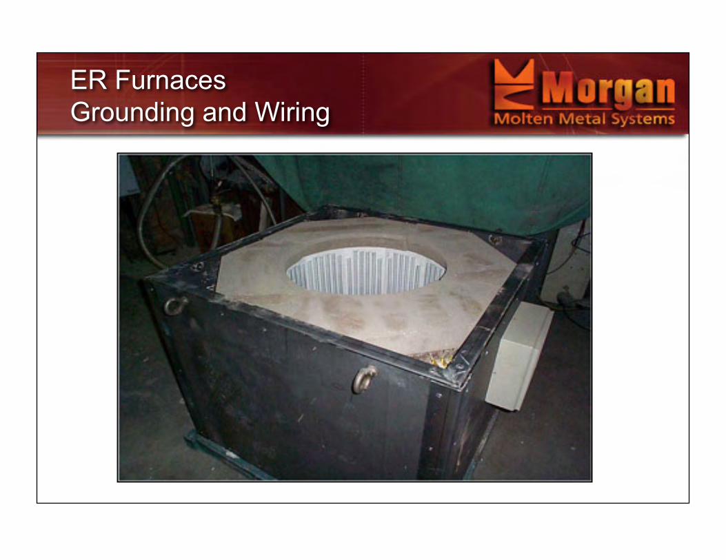
ER Furnaces
Grounding and Wiring
Terminal connections should be protected and arranged toprevent closing circuit in event of current leakage.
Do not allow live conductors to come in contact withoperators.
Protected Unprotected

ER Furnaces
Grounding and Wiring

ER Furnaces
Grounding and Wiring
ER Furnaces
Grounding and Wiring

ER Furnaces
Grounding and Wiring

Earth Fault – Metal Leak
Crucible and molten metal are not practical to ground
to earth, so how do you protect operators?
2 ways this can be done:
RCD or residual current devise in control cabinet or
plant electrical system.
Sensing relay with rapid disconnect.
And of course always ground the metal frame work.
Example of the pin hole leak.

Pin Hole Leak
Pin hole in crucible wall.
Metal stream makes
contact with live element
wire
Operator completes
circuit while baling out

Easy Access for
Maintenance
Failed Elements should be
replaced to avoid cool zones on
crucible.
Easy access to terminal
connections and element wires to
check for loose connections and
thermal couples
Check for metal spills or splash

Changing Crucibles
Preventative Maintenance
Recommended crucible change every 6 months.
Why?
Saves energy and allows for proper maintenance
of the furnace - check connections, survey
furnace, keeps thermal transfer consistent.
In holding applications crucible campaigns of 12
months not uncommon.

Temperature Control
Critical to prevent runaway energy input andconserve energy.
Proper pyrometry shouldbe located in metal bathand furnace chamber.
Procedures should beestablished to monitor,manual or electricalcontrols.

Temperature Control
Newer Crucible
Furnaces incorporate a
temperature controller and
safety measures to prevent
temperature overshoot and
protect element
panels/wire from exceeding
use limit

Gas Fired Crucible Furnaces
Design Considerations
1. Remote ignition (manual is scary!)
2. Exhaust gas extraction that protects work area
3. Redundant fail safe systems for both burnerfailure and molten metal leakage.
4. Temperature controls to prevent temperatureovershoot and run away chamber temps.
5. Easy access for maintenance.
6. Covers, drain holes and top rings.
7. Proper insulation.

Combustion Explosion Hazards
Basic Rules to Follow:1. Establish flame immediately after air/gas mixture is
turned on and, once lit, keep it stable
2. Keep cover open
3. Never disconnect safety devices, pressure switches, inorder to keep furnace working
4. Maintain burner, paying close attention to wear
Igniting manual gas fired furnaces can be
extremely dangerous, particularly from
cold.

Redundant
Fail Safe Systems
Easy access for
maintaining burner
Drain hole with diverter
to spilt metal drainage
area
Open area to prevent
gas build up.

Typical fuel fired crucible furnaces
with brick or refractory castable linings
This furnace is
12% efficient,
consuming 4000
BTU’s to melt 1
pound of
aluminium to
pouring
temperature of
1250 F.
Furnace data exhaust stack temp 2205*F

Design Considerations –
Flue Gas
Important exhaust gases are captured and
extracted from workplace.
Previous slide shows unsafe exhausting
creating hazardous conditions for operator
from burns both direct and radiant and
from harmful emissions, such as CO and
NOX vented into the immediate work area.

Proper Venting
Specially designed exhaust
extensions that capture hot
gasses and channel them to
either an open type foundry
roof or an exhaust duct are
best. The double skin
design of the exhaust
extension presents a
surface that is not a danger
from burning

Insulating the Furnace
Low mass
thermal
lining
protects
operators
and
prevents
heat loss.
Shell temps recorded at 350 F, open drain hole
with temps recorded at 2100 F

Multiple Component Insulation Package
1. Radiant Panels – a dense refractory, panel that diffuses radiant
energy evenly through the furnace chamber
2. Thermal Ceramic – SF 607 bulk fiber compacted to 13 pcf
3. BTU Block – a microporous insulation on inside surface of steel
shell
Insulating the Furnace –
Alternative System

Radiant Panels interlock and are self supporting
Insulating the Furnace –
Alternative System

Insulating the Furnace –
Alternative System

Radiant Panels
for Gas Fired Furnaces

Additional Information
on Safety
www.morganmms.com
Go to Library section and find downloadable
version of this presentation
and the safety document:
“Metal Melting Furnaces and Ancillary
Equipment – Guidance for their Safe Use”

System Approach to Crucible and
Furnace – NO FINGER POINTING
Morganite Melting Systems22 North Plains Industrial Road Unit 1
Wallingford CT. 06492
Telephone: (203) 697-0808
Facsimile: (203) 265-6267
E-Mail: [email protected]

Dual Energy Furnace
Flexible Option
Die Cast, Permanent Mold,
Foundry

Start with Element Panels Designed
to Last 2 Years – Guaranteed!