whose responsibility is it? design responsibility - … · whose responsibility is it? ... • not...
TRANSCRIPT
1
Common Pitfalls in Steel Joist Specification
Whose responsibility is it?
• Joist supplier?• Steel fabricator?• Contractor?• Other trades?• Specifier?
Design Responsibility
• Design of standard joists per Steel Joist Institute Specifications
• Design of special joists for specified load case(s)• Determining bridging requirements
– Wind uplift– Lateral bracing of top chord if required (SSR)
Joist Supplier’s responsibilities include
Standard Assumptions
• SJI Standards apply– Seat depth– Live load deflection is span/360– Camber per chart to offset dead load
• Joists are laterally braced by roof deck• All joist design requirements are specifically stated
on structural drawings• Loads are distributed to panel points
SJI Code of Practice assumes
Steel Joist Institute
• SJI Specification is a performance spec– References load table– Specifies how joist is to be designed
• No requirement for any physical size• Bearing depths• Bridging requirements

2
Design Responsibility
• Determining framing scheme• Calculating wind pressure from wind speed • Determining load requirements or load
combinations from building codes• Determining loads from mechanical drawings• Designing lateral bracing system• Connection design
Joist supplier’s responsibilities do not include
LRFD Load Combinations
• Special design joists• Specifying professional will need to spell out
– Unfactored loads• D – dead• L – live (occupancy & equipment)• Lr – roof live • S – snow live• R – rainwater
– Load combinations– ASCE 7 or other cases as deemed appropriate
Deflection
• SJI load tables show a live load which will produce a deflection of L/360 – Part of the standard design process
• More or less severe limits can be specified– L/600 (within reason)– L/240 for total load
Horizontal Movement
• Scissor joists and arches will move horizontally under load
• We can control, but not eliminate this deflection
Some deflection criteria we can’t meet…
• “…no deflection under live load…”• For KCS joist, “Maximum deflection shall be
limited to…”• “Deflection at end of joist extension shall be
limited to…”• Deflection limit of L/600 on long joist
Design Responsibility
• Optimizing framing scheme• Sizing joists for special loads• Coordination with sprinkler systems• Dimensional information
– Web layouts– Special configurations– Seat depths
Vulcraft can assist with
3
Drawing Review
• Engineer of record– Loads– Structural issues
• Contractor– Building dimensions– Attachment locations
• Steel detailer– Bearing details– Dimensions
All verified items must be answered
Design Calculations
• For approval?– Data used is generally incomplete– Loads and dimensions still to be verified– Preparation at this point requires extra work for joist
supplier
• For record?– Data actually used for joist production– Reflects what was supplied– No additional steps in joist supplier’s work flow
What causes dimensional conflicts?
• Sloped top chords• Bearing depths• Bearing lengths
Depth of Joists with Sloped Chords
• SJI designation depth is at centerline
• Exception is offset double pitch – ridgeline depth
• Not limited to catalog depths
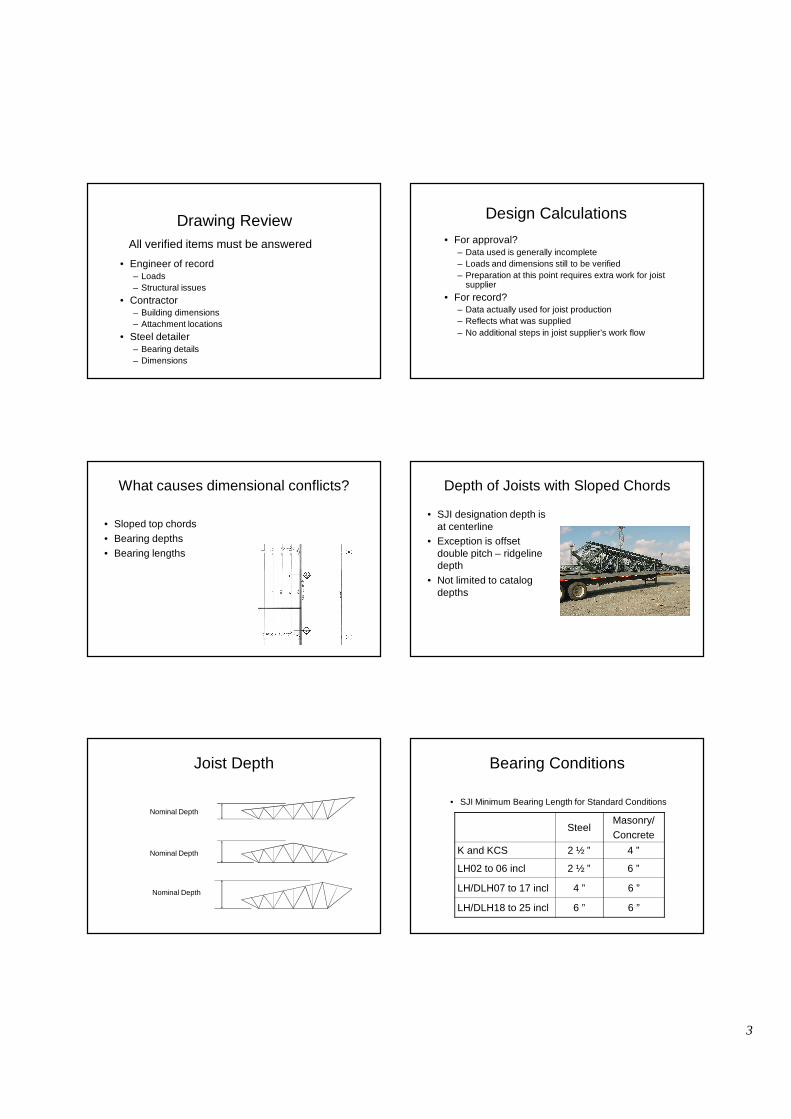
Joist Depth
Nominal Depth
Nominal Depth
Nominal Depth
Bearing Conditions
• SJI Minimum Bearing Length for Standard Conditions
SteelMasonry/Concrete
K and KCS 2 ½ ” 4 ”
LH02 to 06 incl 2 ½ ” 6 ”
LH/DLH07 to 17 incl 4 ” 6 ”
LH/DLH18 to 25 incl 6 ” 6 ”

4
Dimension Definitions• Base length outside of seat to outside of seat
4” 4”
Base Length
For K series
Dimension Definitions• Base length outside of seat to outside of seat
4”
Base Length
Minimum
Bearing on Masonry
Reaction
Prevent joist from loading
the face of the wall
Bearing Conditions
Base Length
2”
R
• SJI Standard Bearing Length -Masonry or Concrete
2” @ K
4” @ LH, G
Bearing Conditions
• SJI Standard Bearing Length -Masonry or Concrete
Base Length
Assume to be zero
2” 2” @ K
4” @ LH, G
R
Steel Joist Institute
• SJI Standard Bearing Length -Steel
Base Length
2”
R
2½” @ K, LH02-06 2” @ LH7-17
Always better to have as much
bearing as possible up to
maximum based on type of joist.
4” @ LH18-25
Dimension Definitions• Base length outside of seat to outside of seat
4” 4”
Base Length TCXTCX
Overall Length

5
Steel Joist Institute
• Minimum bearing– Ensures reaction will not overstress support– Not too close to face of wall– Not too near toe of beam flange
• Alternatives– EOR verify support design– Stagger joist bearing– Both can complicate approval process
Steel Joist Institute
• Maximum bearing– Ensures web will not foul with support– Reaction cannot move back due to geometry– Bearing capacity is not normally the issue
• Alternative– Deeper bearing– Increases clearance– Requires coordination
• Avoid bearing on top chord extension
Wider Supports• Base length outside of seat to outside of seat
6”
What if more bearing is required?
Dimension Definitions• Base length outside of seat to outside of seat
4”
Base LengthBearing Seat
Reaction
Anything past the 4” bearing seat is a tcx
Overall Length
2”
TCX
Deeper Bearing• Base length outside of seat to outside of seat
4”Bearing Seat
Reaction
Seat depth can be increased, but elevations
must be coordinated
Base LengthClear Bearing6”
Deeper Bearing
• High uplift can require deeper seats
4”Bearing Seat
Reaction
Compression in end web too large for rodMust use double angles
Base Length

6
Girder Seats
• SJI Standard seat depth– Most Joist Girders 7 ½ inches
• Left of blue line
– Large Joist Girders 10 inches or more• Right of blue line
See pages 103-111 of Vulcraft manual
Different Bearing Depths in One Location
• Increase seat depth of smaller member• Never try to decrease the seat depth of the
larger member• Reasons should be clear from previous
discussion
Extended Ends
• Frequently same depth as bearing seat• SJI type “R”• Bearing seat extends back one panel to develop
capacity
K series 2 ½”LH series 5”
Extended Ends
• Short extensions may only be top chord• SJI type “S”
K series 2 ½”LH series 5”
Extended Ends
• Short extensions may only be top chord• SJI type “S”• Bearing seat may extend out for dimensional
reasons, but is not considered in design
K series 2 ½”LH series 5”
Extended Ends
• Specifying type “S” can be confusing• Is it important that the seat not continue?• Or is it only load that is meant?
K series 2 ½”LH series 5”

7
Extended Ends
• “If the loading diagram for any condition is not shown, the joist manufacturer will design the extension to support the uniform load indicated in the K-Series Joist Load Table for the span of the joist.”
• What can happen– 10K1 x 12-00 supports 200 plf total load– From the SJI load table, wTL = 550– Top chord extension 3-00– Deflection for 550 plf exceeds L/120 with the largest members
available
• But we could design for 200 plf with no problem
Extended Ends
• Best option for long extension• Define loads on contract documents• Deflection requirements must include loads
What about sloped joist bearing seats?
• When required?• What will the seat depth be?
Sloped Bearing
• Increased depth required – See page 42 or 47 of
Vulcraft manual• Depths shown
– Minimums (more is OK)– Clearance for end web– Clearance for extension
• Contact Vulcraft for extreme slope rates (6:12 or more)
Sloped Bearing
• Sloped seats required– Assumed 4” bearing– Maximum gap is 1/8”– Slope greater than 3/8:12
• Sloped seats not required– Slope is less that 3/8:12– No top chord extension, or
top chord only
gap
Sloped Bearing
• Sloped seats required– Long bearing length– R type extension– Maximum slope for
standard bearing will become less than 3/8:12
• Similar for LH joists
gap
bearing
8
Sloped Bearing
• Sloped seat depth– End of base length– Not necessarily centerline
of bearing• Similar for LH joists
Seat Depth
5”
4”
c. l.
How to design for concentrated loads?
• Double joist? • Standard joist?• KCS series?• Special joist?
– Add load– Load diagram
Option 1
Use Double Joists• Generally conservative• Simple• Not very efficient• Potential problems with
framing & bridging
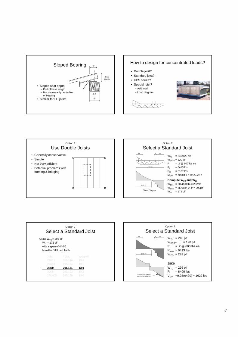
WTL = 240/120 plfWDRIFT= 120 plfP = 2 @ 600 lbs eaRL = 6413 lbsRR = 6187 lbsMMAX = 70584 k-ft @ 23.22 ft
Compute W EQ and W LL
WEQ1 = 2(6413)/44 = 292plfWEQ2 = 8(70584)/442 = 292plfWLL = 172 plf
L = 44-00
23.22 FT
Shear Diagram
14’ 4’ 12’
Option 2
Select a Standard Joist
Using WEQ = 292 plf WLL = 172 plf with a span of 44-00from the SJI Load Table
Joist TL/LL Weight/ft22K11 311/146 13.824K10 298/154 13.1
� 28K9 295/181 13.0 30K8 291/192 13.228LH05 297/180 13.0
Option 2
Select a Standard JoistWTL = 240 plfWDRIFT = 120 plfP = 2 @ 600 lbs eaRMAX = 6413 lbsWEQ = 292 plf
28K9WTL = 295 plfR = 6490 lbsVMIN =0.25(6490) = 1622 lbs
23.22 FT
14’ 4’ 12’
Required shear not covered by selection
Option 2
Select a Standard Joist
9
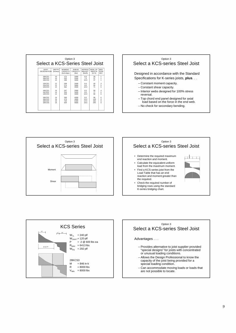
JOIST DESIGNATION 10KCS1 10KCS2 10KCS3 12KCS1 12KCS2 12KCS3 14KCS1 14CSS2 14KCS3
16KCS2 16KCS3 16KCS4 16KCS5
DEPTH (inches) 10 10 10 12 12 12 14 14 14 16 16 16 16
MOMENT CAPACITY (inch-kips) 172 225 296 209 274 362 247 324 428 349 470 720 934
SHEAR CAPACITY (lbs) 2000 2500 3000 2400 3000 3500 2900 3400 3900 4000 4800 5300 5800
APPROX WEIGHT (lbs/ft) 6.0 7.5 10.0 6.0 8.0 10.0 6.5 8.0 10.0 8.5 10.5 14.5 18.0
MOM. OF INERTIA (in^4) 29 37 47 43 55 71 59 77 99 99 128 192 245
BRD ROW SEC 1 1 1 3 5 5 4 6 6 6 9 9 9
Option 3
Select a KCS-Series Steel Joist
Designed in accordance with the StandardSpecifications for K-series joists, plus. . .
– Constant moment capacity.– Constant shear capacity.– Interior webs designed for 100% stress
reversal.– Top chord end panel designed for axial
load based on the force in the end web.– No check for secondary bending.
Option 3
Select a KCS-series Steel Joist
Moment
Shear
Option 3
Select a KCS-series Steel Joist
V
• Determine the required maximum end reaction and moment.
• Calculate the equivalent uniform load from the maximum moment.
• Find a KCS-series joist from the Load Table that has an end reaction and moment greater than the required.
• Check the required number of bridging rows using the standard K-series bridging chart.
M
Option 3
Select a KCS-series Steel Joist
WTL = 240 plfWDRIFT= 120 plfP = 2 @ 600 lbs eaRMAX = 6413 lbsWEQ = 292 plf
28KCS3M = 846 in-kR = 8000 lbsVMIN = 8000 lbs
23.22 FT
14’4’ 12’
KCS Series
Advantages . . .
– Provides alternative to joist supplier provided “special designs” for joists with concentrated or unusual loading conditions.
– Allows the Design Professional to know the capacity of the joist being provided for a special loading condition.
– Can accommodate moving loads or loads that are not possible to locate.
Option 3
Select a KCS-series Steel Joist
10
Disadvantages . . .
– Much heavier than standard designation or “special design” joists.
– More expensive per unit than standard K-seriesjoists. (But overall project may be more
economical.)
Option 3
Select a KCS-series Steel Joist
REMEMBER . . .– The equivalent uniform load calculated from the
required resisting moment must not exceed 550 plf.– If the equivalent uniform load exceeds 550 plf, you
have two options :• a) Use 2 KCS-series joists to provide a total
moment and shear capacity equal to the required. • b) Use an LH-series joist selected for the
equivalent uniform load. Provide a Load Diagram for this option.
Option 3
Select a KCS-series Steel Joist
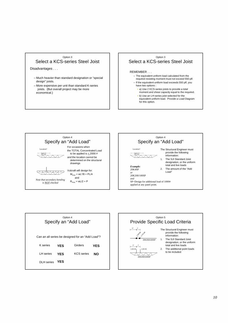
For occasions when the TOTAL Concentrated Load
to be applied is < 2000 # and the location cannot be
determined on the structural drawings
Vulcraft will design for:Mmax = wL2/8 + PL/4
andRmax = wL/2 + P
RTU
Location?
Note that secondary bendingis NOT checked
Option 4
Specify an “Add Load”
The Structural Engineer must provide the following information:
1. The SJI Standard Joist designation, or the uniform total and live loads
2. The amount of the “Add Load”
RTU
Location?
Example:20K4SPor20K200/100SPandSP=Design for additional load of 1000# applied at any panel point.
Option 4
Specify an “Add Load”
Can an all series be designed for an “Add Load”?
K series Girders
LH series KCS series
DLH series
YES
YES
YES
YES
NO
Option 4
Specify an “Add Load”
The Structural Engineer must provide the following information:
1. The SJI Standard Joist designation, or the uniform total and live loads
2. The additional point loads to be included
4’12’
1.0/0.5K 1.0/0.5K
12’ 4’
20K200/100SP
20K200/100SP
Option 5
Provide Specific Load Criteria
11
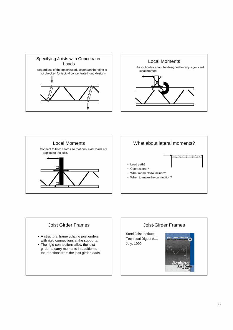
Regardless of the option used, secondary bending is not checked for typical concentrated load designs
Specifying Joists with Concetrated Loads
Joist chords cannot be designed for any significant local moment
Local Moments
Connect to both chords so that only axial loads are applied to the joist.
Local Moments What about lateral moments?
• Load path?• Connections?• What moments to include?• When to make the connection?
Joist Girder Frames
• A structural frame utilizing joist girders with rigid connections at the supports.
• The rigid connections allow the joist girder to carry moments in addition to the reactions from the joist girder loads.
Joist-Girder Frames
Steel Joist InstituteTechnical Digest #11July, 1999
12
Joist Girder Frames
Determine approximate moment of inertia of joist girder:
IJG = 0.027 NPLdN – number of joist spacesP – panel point loadL – length in feetd – depth in inches
Joist Girder Frames
Determine approximate moment of inertia of joist girder:
Joist Girder Frame
• Determine area of joist girder cross section– Refer to Vulcraft catalog for girder weight– AJG = girder weight (plf) / steel density (490
pcf)
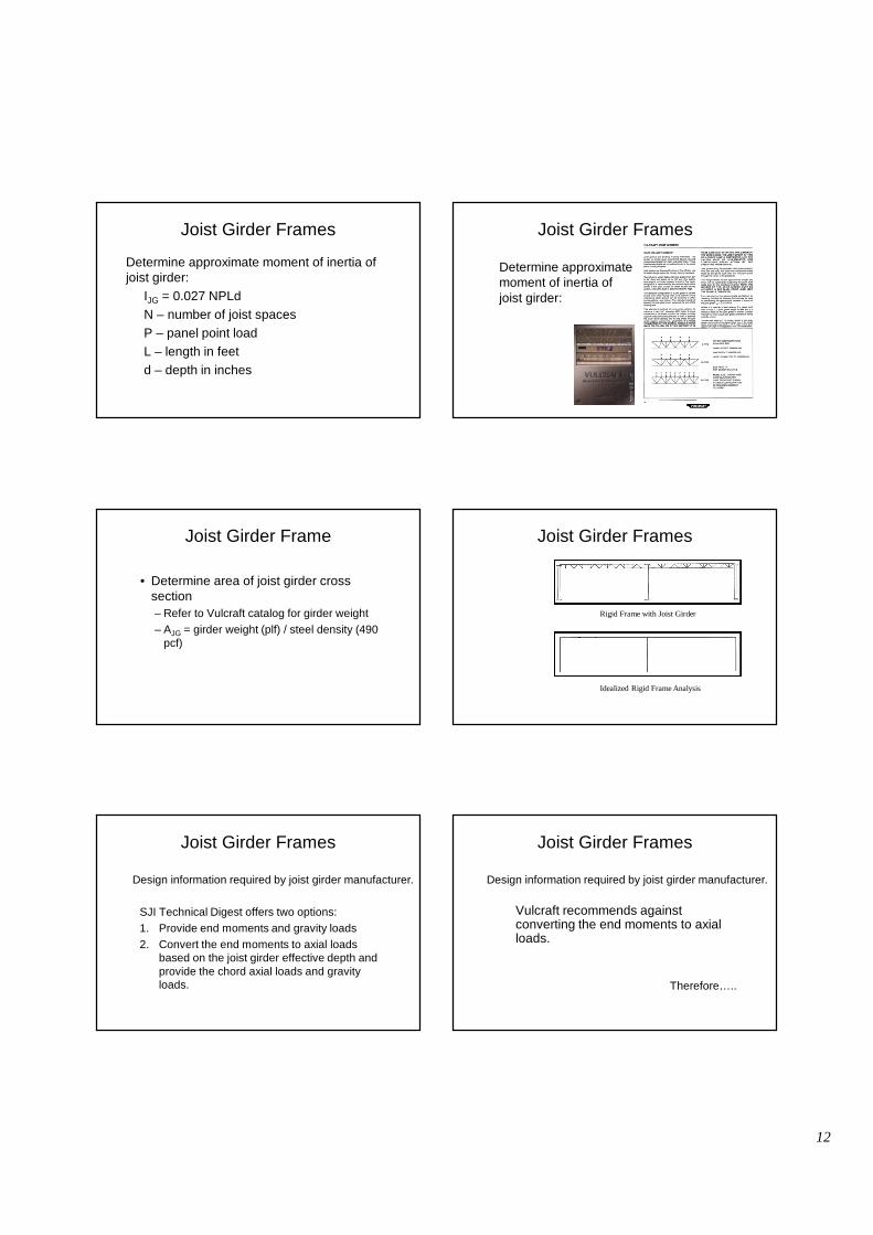
Joist Girder Frames
Rigid Frame with Joist Girder
Idealized Rigid Frame Analysis
Joist Girder Frames
SJI Technical Digest offers two options:1. Provide end moments and gravity loads2. Convert the end moments to axial loads
based on the joist girder effective depth and provide the chord axial loads and gravity loads.
Design information required by joist girder manufacturer.
Joist Girder Frames
Vulcraft recommends against converting the end moments to axial loads.
Therefore…..
Design information required by joist girder manufacturer.

13
Joist Girder Frames
Design information required by joist girder manufacturer.
� Standard joist girder designation
� Lateral moments due to wind and/or earthquake� Live load moments� (Axial loads)� (Net uplift)
Joist Girder Frames
Connection Details
Basic Connection
NO WELD
Welded Basic Connection
BOTH ANGLES 3/16” 6”
TYP.1/4” 5”
Eccentricity with Basic Connection
BOTH ANGLES 3/16” 6”
TYP.1/4” 5”
e
M
F
F
Maximum Pa
4 k to 10 k
Joist Girder Frames
• Commentary and Suggestions in Vulcraft catalog

14
Welded Basic Connection with Tie
BOTH ANGLES 3/16” 6”
2 ANGLESTYP.1/4” 5”
Girder Moment Plate
BOTH ANGLES
Joist Girder Frames
• Connection Details
Axial Loads & Lateral Moments• Can be applied to
• K-series• LH, DLH, SLH-series• Joist Girders
• Connection must transfer the load
Moment Connections
• Consider load path• No axial load capacity for
7 ½ inch deep girder seats
• Sloped seats should not transfer axial load
Moment Connections
• Any load applied after the bottom chord extension is welded creates an end moment
• Live and dead load moments are induced