white paper7 12 2012 comm protocols - fischer connectors · used in fi elds requiring faultless...
TRANSCRIPT
Wh
ite
Pa
pe
r
C O N N E C T O R S
Headquarters
Fischer Connectors SACh. du Glapin 201162 Saint-PrexSwitzerlandPhone +41 21 800 95 95mail@fi scherconnectors.chwww.fi scherconnectors.com Edition 1.0
Communication Protocols
SummaryThis document provides an overview of the different data protocols currently used and how
connectors and cable assembly performances are linked to these protocols. It explains the impor-
tance of using the right connectors and cable assembly solutions when connecting an emitter to
a receiver, and the possible impact on the performance. It shows that when choosing the right
connector, there will be no performance loss transferring data. This document also gives an over-
view of the performance of several Fischer Connectors’ products related to the different types of
communication protocols.
Index
Introduction page 1
1. Information Exchange page 2
2. The Open Systems Interconnection (OSI) model page 2
3. Layers of interest for physical connection of Fischer Connectors’ connectors page 3
4. Details of well-known protocols page 3
5. Maximum data bit rate as un function of cable type, length & protocol page 6
6. Fischer Connectors tests & comparison page 6
7. Results page 10
8. Conclusion page 10
9. Q&A page 11
IntroductionA communication protocol is a system of digital message formats and rules for exchanging messages in or between computing systems and in telecommunications. A protocol may have a formal description. Protocols may include signaling, authentication and error detection and correc-tion capabilities.
A protocol defi nes the syntax, semantics, and synchronization of communication; the specifi ed behavior is typically independent of how the protocol will be implemented. A protocol can be im-plemented as hardware, software or both. Communications protocols have to be agreed upon by the parties involved. To reach agreement, a protocol may be developed into a technical standard.
About Fischer Connectors Fischer Connectors has been designing, manufacturing and distributing high performance connec-tors and cable assembly solutions for almost 60 years. Known for their reliability, precision and resistance to demanding and harsh environments, Fischer Connectors’ products are commonly used in fi elds requiring faultless quality, such as medical equipment, industrial instrumentation, measuring and testing devices, broadcast, telecommunication and military forces worldwide. Pri-mary design and manufacturing facilities are located in Saint-Prex, Switzerland, with subsidiaries and distributors located worldwide.
By: David Magni, product manager, Fischer Connectors,
David Magni focuses on innovation and creating products that make a difference in the lives of users. He has been working closely with Fischer Connectors’ customers to deliver new connector technology to the marketplace.

Wh
ite
Pa
pe
r
Edition 1.0 Page 2
C O N N E C T O R SC O N N E C T O R S
Communicat ion Protocols
1. Information exchangeAlready implemented in Europe and Canada, the new standard embodies a new philosophy and approach to regulatory requirements that is having a dramatic effect on medical device development in other markets throughout the world.
Communicating systems use well-defi ned formats for exchanging messages. Each message has an exact meaning intended to provoke a defi ned response from the receiver. A protocol therefore describes the syntax, semantics, and synchronization of communication. A programming language describes the same for computations, so there is a close analogy between protocols and programming languages: protocols are to communications what programming languages are to computations.
The information exchanged between devices on a network or other communications medium is gover-ned by rules or conventions that can be set out in a technical specifi cation called a communication pro-tocol standard. The nature of the communication, the actual data exchanged and any state-dependent behaviors are defi ned by the specifi cation.
In contrast, communicating systems have to communicate with each other using shared transmission media, because there is no common memory. Transmission is not necessarily reliable and can involve different hardware and operating systems on different computers or computer systems.To implement a networking protocol, the protocol software modules are interfaced with a framework implemented on the machine’s operating system. This framework implements the networking functio-nality of the operating system. The best known frameworks are the TCP/IP model and the OSI model.
2. The Open Systems Interconnection (OSI) model 1
The Open Systems Interconnection (OSI) model (ISO/IEC 7498-1) is a product of the Open Systems Interconnection effort at the International Organization for Standardization. It is the way to characterize and standardize the functions of a communications system in terms of abstraction layers. Similar com-munication functions are grouped into logical layers. A layer serves the layer above it, and is served by the layer below it.
For example, a layer that provides error-free communications across a network provides the path nee-ded by applications above it, while it calls the next lower layer to send and receive packets that make up the contents of that path. Two instances at one layer are connected by a horizontal connection on that layer.
1 Source Wikipedia
OSI Model
Data unit Layer Function
Host Layers Data 7. Application Network process to application
6. Presentation Data representation, encryption and decryption, convert machine dependent data to machine independent data
5. Session Interhost communication, managing sessions between applications
Segments 4. Transport End-to-end connections, reliability and flow control
Media layers Packet/datagram 3. Network Path determination and logical addressing
Frame 2. Data link Physical addressing
Bit 1. Physical Media, signal and binary transmission

Wh
ite
Pa
pe
r
Edition 1.0 Page 3
C O N N E C T O R S
Communicat ion Protocols
3. Layers of interest for physical connection of
Fischer connectors’ connectors 2
2 Source Wikipedia3 Source Wikipedia
Layer 1: physical layer
The physical layer defi nes electrical and physical specifi cations for devices. In particular, it defi nes the relationship between a device and a transmission medium, such as a copper or fi ber optical cable. This includes the layout of pins, voltages, line impedance, cable specifi cations, signal timing, hubs, repea-ters, network adapters, host bus adapters (HBA used in storage area networks) and more.
The major functions and services performed by the physical layer are:■ Establish and terminate a connection to a communications medium.■ Participate in the process where the communication resources are effectively shared among multiple
users. For example, contention resolution and fl ow control.■ Responsible for modulation or conversion between the representation of digital data in user equip-
ment and the corresponding signals transmitted over a communications channel. These are signals operating over the physical cabling (such as copper and optical fi ber) or over a radio link.
Parallel SCSI buses operate in this layer, although it must be remembered that the logical protocol is a transport layer protocol that runs over this bus. Various physical-layer Ethernet standards are also in this layer; Ethernet incorporates both this layer and the data link layer.
Layer 2: data link layer
The data link layer provides the functional and procedural means to transfer data between network entities and to detect and possibly correct errors that may occur in the physical layer. Originally, this layer was intended for point-to-point and point-to-multipoint media, characteristic of wide area media in the telephone system.
Both WAN and LAN service arranges bits from the physical layer into logical sequences called frames. Not all physical layer bits necessarily go into frames, as some of these bits are purely intended for phy-sical layer functions. Following are the functions of data link layer:■ Framing■ Physical Addressing■ Flow Control■ Error Control■ Access Control■ Media Access Control(MAC)
4. Details of well-known protocols 3
1) USB: Layer 1 in OSI model
Universal Serial Bus (USB) is an industry standard developed in the mid-1990s that defi nes the cables, connectors and communications protocols used in a bus for connection, communication and power supply between computers and electronic devices.
USB was designed to standardize the connection of computer peripherals, such as keyboards, pointing devices, digital cameras, printers, portable media players, disk drives and network adapters to personal computers, both to communicate and to supply electric power. It has become commonplace on other devices, such as smartphones, PDAs and video game consoles. USB has effectively replaced a variety of earlier interfaces, such as serial and parallel ports, as well as separate power chargers for portable devices.
As of 2008 approximately 6 billion USB ports and interfaces were in the global marketplace, and about 2 billion were being sold each year. A group of seven companies began the development of USB in 1994: Compaq, DEC, IBM, Intel, Microsoft, NEC and Nortel. The goal was to make it fundamentally easier to connect external devices to PCs by replacing the multitude of connectors at the back of PCs, addres-sing the usability issues of existing interfaces, and simplifying software confi guration of all devices connected to USB, as well as permitting greater data rates for external devices.
The original USB 1.0 specifi cation, which was introduced in January 1996, defi ned data transfer rates of 1.5 Mbit/s “Low Speed” and 12 Mbit/s “Full Speed”.

Wh
ite
Pa
pe
r
Edition 1.0 Page 4
Communicat ion ProtocolsC O N N E C T O R S
A. USB Standard Type A plug, the most common USB plug
The USB 2.0 specifi cation was released in April 2000 and was ratifi ed by the USB Implementers Forum (USB-IF) at the end of 2001. Hewlett-Packard, Intel, Lucent Technologies (now Alcatel-Lucent), NEC and Philips jointly led the initiative to develop a higher data transfer rate, with the resulting spe-cifi cation achieving 480 Mbit/s, a forty times increase over the original USB 1.1 specifi cation.The USB 3.0 specifi cation was published on 12 November 2008. Its main goals were to increase the data transfer rate (up to 5 Gbit/s), to decrease power consumption, to increase power output, and to be backwards-compatible with USB 2.0. USB 3.0 includes a new, higher speed bus called SuperSpeed in parallel with the USB 2.0 bus. For this reason, the new version is also called SuperSpeed. The fi rst USB 3.0 equipped devices were presented in January 2010.
Connector types
Types of USB connectors left to right (ruler in centimeters): Micro-B plug, a non-USB proprietary plug, Mini-B plug (5-pin, upside down), Standard-A receptacle (upside down), Standard-A plug, Standard-B plug
There are several types of USB connectors, including some that have been added while the speci-fi cation progressed. The original USB specifi cation detailed Standard-A and Standard-B plugs and receptacles; the B connector was necessary so that cabling could be plug ended at both ends and still prevent users from connecting one computer receptacle to another. The fi rst engineering change notice to the USB 2.0 specifi cation added Mini-B plugs and receptacles.
To reliably enable a charge-only feature, modern USB accessory peripherals now include charging cables that provide power connections to the host port but no data connections, and both home and vehicle charging docks are available that supply power from a converter device and do not include a host device and data pins, allowing any capable USB device to be charged or operated from a standard USB cable.

Wh
ite
Pa
pe
r
Edition 1.0 Page 5
Communicat ion ProtocolsC O N N E C T O R S
Cabling
The data cables for USB 1.x and USB 2.x use a twisted pair to reduce signal noise and crosstalk. USB 3.0 cables contain twice as many wires as USB 2.x to support SuperSpeed data transmission, and are thus larger in diameter.
The USB 1.1 Standard specifi es that a standard cable can have a maximum length of 3 meters with devices operating at Low Speed (1.5 Mbit/s), and a maximum length of 5 meters with devices operating at Full Speed (12 Mbit/s).
SB 2.0 provides for a maximum cable length of 5 meters for devices running at Hi Speed (480 Mbit/s). The USB 3.0 standard does not directly specify a maximum cable length, requiring only that all cables meet an electrical specifi cation: for copper cabling with AWG 26 wires the maximum practical length is 3 meters (9.8 ft).
Transmission ratesThe theoretical maximum data rate in USB 2.0 is 480 Mbit/s (60 MB/s) per controller and is shared amongst all attached devices.
Typical hi-speed USB hard drives can be written to at rates around 25–30 MB/s, and read from at rates of 30–42 MB/s, according to routine testing done by CNet. This is 70% of the total bandwidth available. Mask Tests, also known as Eye Diagram Tests, are used to determine the quality of a signal in the time domain. They are defi ned in the referenced document as part of the electrical test description for the high-speed (HS) mode at 480 Mbit/s.
B. ETHERNET: layer 2 in OSI model
Ethernet is a family of computer networking technologies for local area networks (LANs).Ethernet was commercially introduced in 1980 and standardized in 1985 as IEEE 802.3.Ethernet has largely replaced competing wired LAN technologies.
The Ethernet standards comprise several wiring and signaling variants of the OSI physical layerin use with Ethernet. The original 10BASE5 Ethernet used coaxial cable as a shared medium.Later, the coaxial cables were replaced by twisted pair and fi ber optic links in conjunction withhubs or switches. Data rates were periodically increased from the original 10 megabits persecond, to 100 gigabits per second.
Systems communicating over Ethernet divide a stream of data into shorter pieces called frames.Each frame contains source and destination addresses and error-checking data so thatdamaged data can be detected and re-transmitted. As per the OSI model, Ethernet providesservices up to and including the data link layer.
The Ethernet physical layer evolved over a considerable time span and encompasses coaxial, twisted pair and fi ber optic physical media interfaces and speeds from 10 Mbit/s to 100 Gbit/s. The most common forms used are 10BASE-T, 100BASE-TX, and 1000BASE-T. All three utilize twisted pair cables and 8P8C modular connectors. They run at 10 Mbit/s,100 Mbit/s, and 1 Gbit/s, respectively. Fiber optic variants of Ethernet offer high performance,electrical isolation and distance (tens of kilometers with some versions).

Wh
ite
Pa
pe
r
Edition 1.0 Page 6
Communicat ion ProtocolsC O N N E C T O R S
6. Fischer Connectors Tests & comparisons
Transmission support Cable-connectors
Receiver Emitter
WARNING WITH NUMBERS & CONVERSION
■ Data rate: 1 Gbit/s = 1000 Mbit/s = 106 bit/s = 125 Mbyte/s ■ English-French conversion: 1 byte = 8 bits = 1 octet ■ General representation: 1 GB = 1 Gigabyte = 1 Gigaoctet = 1 Go, 1 Gb = 1 Gigabit■ 8Gb = 1GB
Flash drive memory size are generally presented in GB, BUT the data bit rate could be presented in Gb/s which is 8 times higher than GB/s.
5. Maximum bit rate and cable length as a function of protocol4
Maximum data bit rate as a function of cable length (from market). That table concerns electrical connec-tors and cables.
4 Source Wikipedia

Wh
ite
Pa
pe
r
Edition 1.0 Page 7
Communicat ion ProtocolsC O N N E C T O R S
Recorder Network analyzer
An RJ45 connector is a physical interface often used to terminate twisted pair cable. The “RJ” stands for Registered Jack, which is a part of the Code of Federal Regulations in the USA. The RJ45 is composed of eight electrical pins.
2. Protocol USB 2.0 : Connector USB 2.0
The USB 2.0 Standard-A type of USB plug is a fl attened rectangle which inserts into a “downstream-port” receptacle on the USB host, or a hub, and carries both power and data. This plug is frequently seen on cables that are permanently attached to a device, such as one connecting a keyboard or mouse to the computer via an USB connection.
USB connections eventually wear out as the connection loosens through repeated plugging and unplugging. The lifetime of an USB-A male connector is approximately 1,500 connect/disconnect cycles, A Standard-B plug—which has a square shape with beveled exterior corners—typically plugs into an “upstream receptacle” on a device that uses a removable cable, e.g. a printer. On some devices, the Type B receptacle has no data connections, being used solely for accepting power from the upstream device. This two-connector-type scheme (A/B) prevents a user from accidentally crea-ting an electrical loop.
The test focuses on the cable system and connector. The goal of the test was to discover, at each measurement, the signal attenuation indicating the frequency of data transfer(system impedance), the data transfer rate and cross-talking.
Below is an overview of the connectors tested to geometric standards and related protocols
1. Protocol Ethernet : Connector RJ45
TESTS DESCRIPTION

Wh
ite
Pa
pe
r
Edition 1.0 Page 8
Communicat ion ProtocolsC O N N E C T O R S
3. Protocol USB 3.0 : Connector USB 3.0
Standard-A
A USB 3.0 Standard-A receptacle accepts either a USB 3.0 Standard-A plug or a USB 2.0 Standard-A plug. Conversely, it’s possible to plug USB 3.0 Standard-A plug into a USB 2.0 Standard-A recep-tacle. The Standard-A is used for connecting to the computer port.
The connector has the same physical confi guration as its predecessor but with more pins forUSB 3.0. The VBUS, D-, D+, and GND pins are required for USB 2.0 support, while for USB 3.0 Stan-dard-A connector, fi ve more pins are included–two differential pairs and one ground (GND_DRAIN). The two additional differential pairs are for SuperSpeed data transfer that supports dual simplex SuperSpeed signaling; while the GND_DRAIN pin is for drain wire termination, and to control EMI and maintain signal integrity. Since USB 2.0 and USB 3.0 ports may coexist on the same machine and look similar, the USB 3.0 connector has a blue insert.
Implementation differences compared to USB 2.0
The USB 3.0 specifi cation is similar to USB 2.0 but with many improvements and an alternate imple-mentation. Earlier USB concepts like endpoints and four transfer types (bulk, control, isochronous and interrupt) are preserved but the protocol and electrical interface are different. The specifi cation defi nes a physically separate channel to carry USB 3.0 traffi c. The changes in this specifi cation make improvements in the following areas:■ Transfer speed – added a new transfer type called Super Speed or SS – 5 Gbit/s ■ Increased bandwidth – instead of one-way communication, USB 3.0 uses two unidirectional data
paths: one to receive data and the other to transmit;■ Power management ■ Improved bus utilization – a new feature is added to let a device asynchronously notify the host of
its readiness (no need of polling);■ Support to rotating media – Bulk protocol is updated with a new feature called Stream Protocol
that allows a large number of logical streams within an Endpoint.
USB 3.0 has transmission speeds of up to 5 Gbit/s, which is 10 times faster than USB 2.0 (480 Mbit/s).
Architecture and features
In USB 3.0 dual-bus architecture is used to allow both USB 2.0 (HIGH Speed/LOW Speed/FULL Speed) and USB 3.0 (Super Speed) operations to take place simultaneously, thus providing backward compatibility. Connections are such that they also permit forward compatibility that is, running USB 3.0 devices on USB 2.0 ports.
4. Protocol HDMI
HDMI (High-Defi nition Multimedia Interface) is a compact audio/video interface for transferring uncompressed digital audio/video data from an HDMI-compliant device (“the source device”) to a compatible digital audio device, computer monitor, video projector, or digital television.[1] HDMI is a digital replacement for existing analog video standards.
Wh
ite
Pa
pe
r
Edition 1.0 Page 9
Communicat ion ProtocolsC O N N E C T O R S
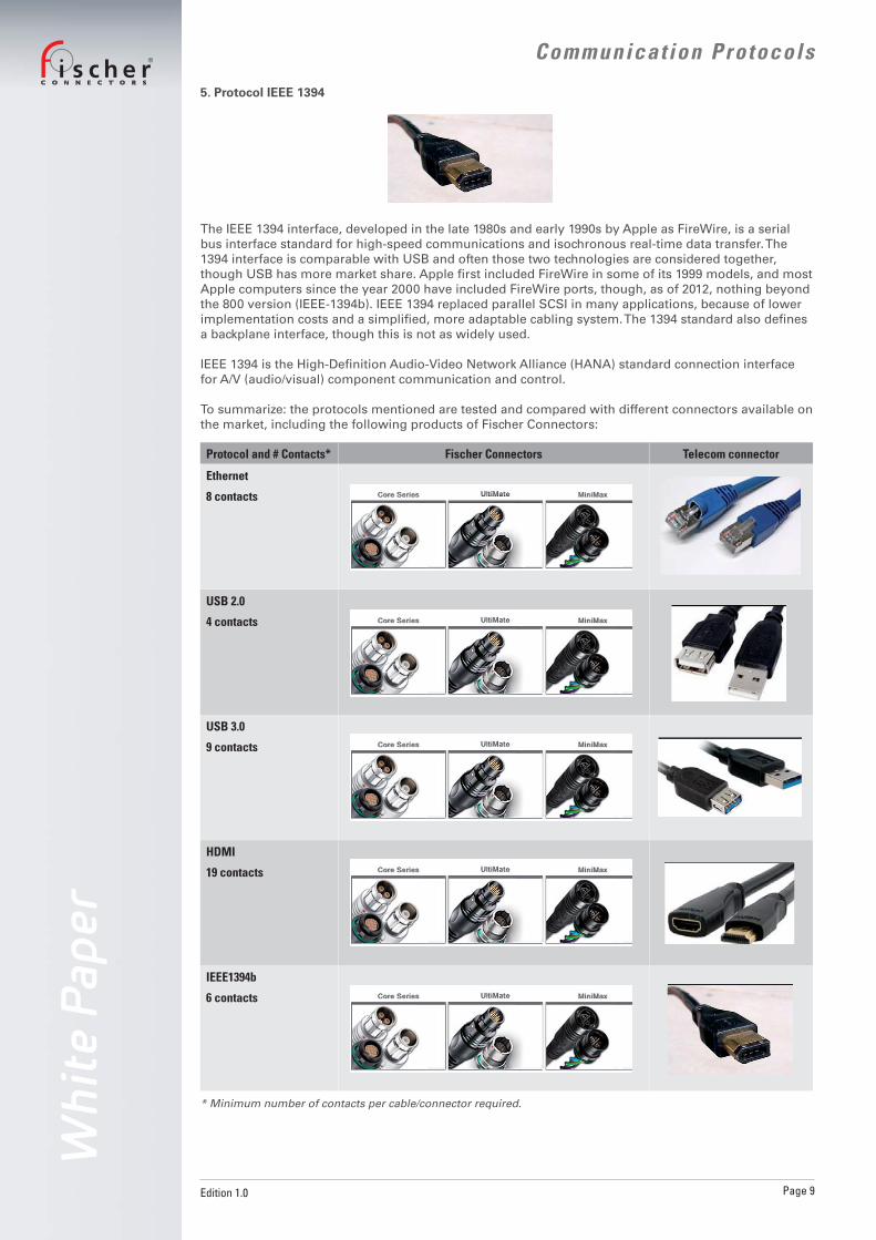
5. Protocol IEEE 1394
The IEEE 1394 interface, developed in the late 1980s and early 1990s by Apple as FireWire, is a serial bus interface standard for high-speed communications and isochronous real-time data transfer. The 1394 interface is comparable with USB and often those two technologies are considered together, though USB has more market share. Apple fi rst included FireWire in some of its 1999 models, and most Apple computers since the year 2000 have included FireWire ports, though, as of 2012, nothing beyond the 800 version (IEEE-1394b). IEEE 1394 replaced parallel SCSI in many applications, because of lower implementation costs and a simplifi ed, more adaptable cabling system. The 1394 standard also defi nes a backplane interface, though this is not as widely used.
IEEE 1394 is the High-Defi nition Audio-Video Network Alliance (HANA) standard connection interface for A/V (audio/visual) component communication and control.
To summarize: the protocols mentioned are tested and compared with different connectors available on the market, including the following products of Fischer Connectors:
* Minimum number of contacts per cable/connector required.
Protocol and # Contacts* Fischer Connectors Telecom connector
Ethernet
8 contacts
USB 2.0
4 contacts
USB 3.0
9 contacts
HDMI
19 contacts
IEEE1394b
6 contacts
Wh
ite
Pa
pe
r
Edition 1.0 Page 10
Communicat ion ProtocolsC O N N E C T O R S
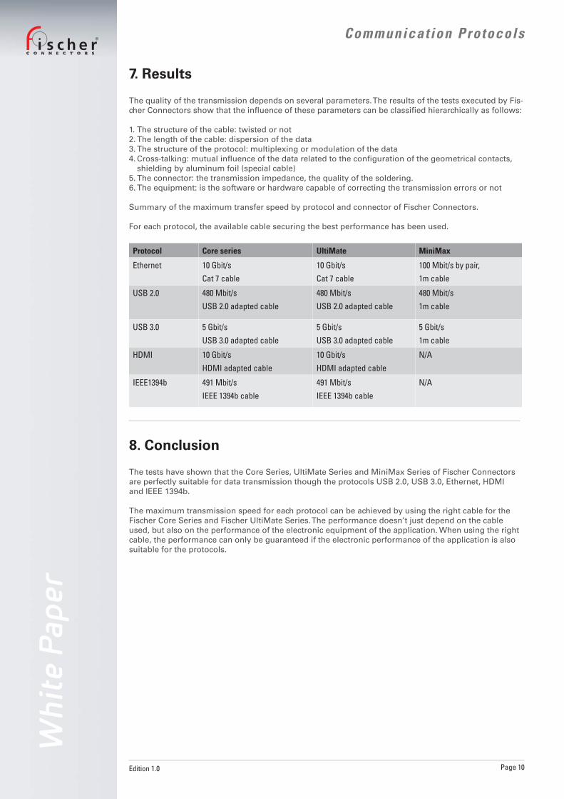
7. Results
The quality of the transmission depends on several parameters. The results of the tests executed by Fis-cher Connectors show that the infl uence of these parameters can be classifi ed hierarchically as follows:
1. The structure of the cable: twisted or not2. The length of the cable: dispersion of the data3. The structure of the protocol: multiplexing or modulation of the data4. Cross-talking: mutual infl uence of the data related to the confi guration of the geometrical contacts,
shielding by aluminum foil (special cable)5. The connector: the transmission impedance, the quality of the soldering.6. The equipment: is the software or hardware capable of correcting the transmission errors or not
Summary of the maximum transfer speed by protocol and connector of Fischer Connectors.
For each protocol, the available cable securing the best performance has been used.
Protocol Core series UltiMate MiniMax
Ethernet 10 Gbit/s
Cat 7 cable
10 Gbit/s
Cat 7 cable
100 Mbit/s by pair,
1m cable
USB 2.0 480 Mbit/s
USB 2.0 adapted cable
480 Mbit/s
USB 2.0 adapted cable
480 Mbit/s
1m cable
USB 3.0 5 Gbit/s
USB 3.0 adapted cable
5 Gbit/s
USB 3.0 adapted cable
5 Gbit/s
1m cable
HDMI 10 Gbit/s
HDMI adapted cable
10 Gbit/s
HDMI adapted cable
N/A
IEEE1394b 491 Mbit/s
IEEE 1394b cable
491 Mbit/s
IEEE 1394b cable
N/A
8. Conclusion
The tests have shown that the Core Series, UltiMate Series and MiniMax Series of Fischer Connectors are perfectly suitable for data transmission though the protocols USB 2.0, USB 3.0, Ethernet, HDMI and IEEE 1394b.
The maximum transmission speed for each protocol can be achieved by using the right cable for the Fischer Core Series and Fischer UltiMate Series. The performance doesn’t just depend on the cable used, but also on the performance of the electronic equipment of the application. When using the right cable, the performance can only be guaranteed if the electronic performance of the application is also suitable for the protocols.

Wh
ite
Pa
pe
r
Edition 1.0 Page 11
Communicat ion ProtocolsC O N N E C T O R S
9. Q&A
1. Are Fischer Connectors’ products suitable for Ethernet protocol?Yes. Fischer Connectors SA has demonstrated that its connectors do not limit the performance of the-protocol transmission. The cable type is the fi rst factor that could strongly infl uence the data transmis-sion.
2. What is the maximum data bit rate?The maximum data bit rate depends strongly on the cable type and length and the electronic approach of the system integrator. The connectors of Fischer Connectors, like any other connector, do not limit the maximum data bit rate. The maximum data bit rate can decrease by multiplication of the number of connectors used on the same device.
3. What is the cross-talking level?That factor is mainly infl uenced by the cable type (twisted pairs/shielding foils, etc) and secondarily, the pin confi guration geometry. Fischer Connectors’ connectors pin confi guration does not induce electro-magnetic perturbation or negatively impact cross-talk protection, and corresponds to standard level of telecom connectors.
4. Is it possible to mix protocols in the same connector?Yes. Again, as each application has its own stakes, such as cable length, protocol types, and electronic devices. The performance of the solution has to be validated for each specifi c application