white paper network convergence and data center bridging … · · 2016-05-10white paper network...
TRANSCRIPT
White paper Network Convergence and Data Center Bridging
www.fujitsu.com
Page 1 of 27
White paper Network Convergence and Data Center Bridging (DCB) in VMware vSphere environments
As Local Area Network (LAN) and Storage Area Network (SAN) technology has matured, it has become very
beneficial to merge them into a common technology. They are converging under Ethernet based technology and
protocols. This paper addresses some of the benefits of this convergence, as driven by virtualization and
technology advancements. Some performance comparisons and Best Practices on how to enable convergence
through iSCSI with Data Center Bridging (DCB) under VMware® environments are presented.
www.fujitsu.com
White paper Network Convergence and Data Center Bridging
Page 2 of 27
1 Introduction.................................................................................................................................................................................................................. 4 2 Technology Data Rates ................................................................................................................................................................................................. 4 3 Ethernet Based SAN Protocols ...................................................................................................................................................................................... 5
3.1 Fibre Channel over Ethernet (FCoE) ........................................................................................................................................................................ 5 3.2 Internet Small Computer System Interface (iSCSI)................................................................................................................................................... 5
4 Data Center Bridging (DCB).......................................................................................................................................................................................... 5 4.1 Priority-based Flow Control (PFC) ............................................................................................................................................................................ 5 4.2 Enhanced Transmission Selection (ETS) .................................................................................................................................................................. 5 4.3 Data Center Bridging Exchange (DCBX) .................................................................................................................................................................. 5
5 Best Practice Recommendations .................................................................................................................................................................................. 6 5.1 Tradeoff between iSCSI and FCoE in Virtual Environments ...................................................................................................................................... 6 5.2 The use of iSCSI with DCB in Virtual Environments .................................................................................................................................................. 6 5.3 Choose which DCBX protocol to use in your configuration (Baseline or IEEE) ......................................................................................................... 8 5.4 Set DCB enabled switches to propagate parameters to the End Devices by setting all End Devices to “Willing” mode.......................................... 8 5.5 Define a dedicated VLAN for all iSCSI traffic and use it in Tagged mode ................................................................................................................. 9 5.6 Set up the Priority for ETS (Enhanced Transmission Selection) feature using weighted round robin algorithm ................................................... 10 5.7 Enable PFC (Priority Flow Control) for the iSCSI traffic class................................................................................................................................... 10 5.8 Wait for the DCBX protocol setting to be transmitted properly and check the status on both the CNA and the Switch ........................................ 10 5.9 Set ETERNUS® Host Response to use Send Target (single response mode). ......................................................................................................... 11
6 Lab Testing ................................................................................................................................................................................................................. 12 6.1 Test Configurations ................................................................................................................................................................................................ 12
6.1.1 Test Configuration for iSCSI......................................................................................................................................................................................... 12 6.2 General Testing Environment ................................................................................................................................................................................ 12
6.2.1 Software Drivers used in the testing........................................................................................................................................................................... 13 6.3 Performance Data Used for Evaluation.................................................................................................................................................................. 13
6.3.1 Selected Vdbench Measured Elements ...................................................................................................................................................................... 13 6.3.2 Collected Vdbench Data Sets ...................................................................................................................................................................................... 13
6.4 Performance Overview .......................................................................................................................................................................................... 14 6.4.1 iSCSI Server Connections without Interference Traffic ................................................................................................................................................. 14 6.4.2 iSCSI Server Connections with Interference Traffic, DCB not Enabled ......................................................................................................................... 15 6.4.3 iSCSI Server Connections with Interference Traffic and DCB Enabled .......................................................................................................................... 15
6.5 Conclusion - iSCSI Performance Loss with Interference Traffic ............................................................................................................................... 16 7 Appendix (Detailed Scripts and Setup Procedures for Test Environment Operations) ............................................................................................... 17
7.1 Details of Settings for Extreme® Networks X670 Switch ........................................................................................................................................ 17 7.2 Details of OneCommand Manager for VMware vCenter ........................................................................................................................................ 18 7.3 Details of setting PXESelect utility of Emulex iSCSI HBA ........................................................................................................................................ 20 7.4 Details of setting iSCSI utility of Emulex iSCSI HBA ................................................................................................................................................ 21
7.4.2 Set IP Address and VLAN ID/Priority at Network Configuration page .......................................................................................................................... 22 7.5 Details of Setting the ETERNUS DX200 S3 ............................................................................................................................................................. 26
www.fujitsu.com
White paper Network Convergence and Data Center Bridging
Page 3 of 27
Table of Figures
Figure 1 - Technology Speeds ………………………………………………………………………………………………………………………………………………………………………………………………………4
Figure 2 - Different layers implement the DCB function in the VMware iSCSI environment ………………………………………………………………………………………………….7
Figure 3 - Emulex OCe14102-U 10Gb CNA Personality Settings …………………………………………………………………………………………………………………………………..8
Figure 4 - Insertion of VLAN Tag in Ethernet Packet …………………………………………………………………………………………………………………………………………………..9
Figure 5 - Configure VLAN ID/Priority – Emulex CNA BIOS …………………………………………………………………………………………………………………………………………………..9
Figure 6 - Test Configuration used for iSCSI ………………………………………………………………………………………………………………………………………………………………….12
Figure 7 - Data Rate and Throughput by Block Size - 100% …………………………………………………………………………………………………………………………………………………14
Figure 8 - Data Rate and Throughput by Block Size - 80% ………………………………………………………………………………………………………………………………………………...14
Figure 9 - iSCSI Performance Loss with Interference Traffic …………………………………………………………………………………………………………………………………………………16
Figure 10 - Emulex Device Management Window ………………………………………………………………………………………………………………………………………………………………….18
Figure 11 - DCB Configuration Window …………………………………………………………………………………………………………………………………………………………………………………..19
Figure 12 - Detail from DCB Configuration Window …………………………………………………………………………………………………………………………………………………20
Figure 13 - Emulex PXESelect Window ………………………………………………………………………………………………………………………………………………………………………………….20
Figure 14 - Emulex PXESelect Utility Window …………………………………………………………………………………………………………………………………………………………………21
Figure 15 - Emulex iSCSI Select Utility Window ………………………………………………………………………………………………………………………………………………………………..21
Figure 16 - Emulex iSCSI Select Utility Window (Controller Properties) ………………………………………………………………………………………………………………………………22
Figure 17 - Emulex iSCSI Select Utility Window (Emulex 0cel1402-U 10Gb C) ……………………………………………………………………………………………………………..22
Figure 18 - Emulex iSCSI Select Utility Window (Configure VLAN ID/Priority) ……………………………………………………………………………………………………………..23
Figure 19 - Emulex iSCSI Select Utility Window (Select DISABLED) ……………………………………………………………………………………………………………………………..23
Figure 20 - Emulex iSCSI Select Utility Window (Select ENABLED) ……………………………………………………………………………………………………………………………..24
Figure 21 - Emulex iSCSI Select Utility Window (Add New iSCSI 1Pv4 Target) …………………………………………………………………………………………………………….24
Figure 22 - Emulex iSCSI Select Utility Window (Select iqn.2000-009.com.fujitsu:) …………………………………………………………………………………………...25
Figure 23 - Emulex iSCSI Select Utility Window (001 iqn.2000 Ipv4 192.168.3.44 3260 Sec Connected) …………………………………………………………..25
www.fujitsu.com
White paper Network Convergence and Data Center Bridging
Page 4 of 27
1 Introduction
Historically Enterprise Data Centers have had two types of networks;
Local Area Networks and Storage Area Networks. These have used
different technologies – Ethernet has dominated the Local Area
Networks, while Fibre Channel has dominated the Storage Area Networks. These different technologies have placed a burden on the
site administrator in terms of both equipment and staff.
Ethernet has become the ubiquitous technology, with ports built into nearly every computer which, when cabled up, “just work”. The speed
of Ethernet continues to scale up as the technology develops, moving
from 10 to 100 to 1000 Mbps, and now going well beyond the 1Gbps
rate. Ethernet has been designed from the beginning to deal with networks where congestion and packet loss are common issues, and
has been very successful in surmounting these traffic management
issues.
Fibre Channel was developed as a low latency, high performance connection technology, based on very low loss network structures. It
has been based on separate network structures, called the fabric, with
specialized management, controls and protocols. Until recently, Fibre Channel has provided higher performance than Ethernet for storage
connections, but as the technology has developed, Ethernet now
supports higher rates than Fibre Channel.
The converged network within a single fabric provides many benefits, including:
■ reduction in space required
■ less heat
■ less electricity
■ common knowledge set
■ reduced maintenance
■ lower cost equipment
Another aspect driving the use of converged networks is the increased
value of virtualization. Server virtualization through products such as
VMware and Hyper-V® require effective and flexible networks between
the servers and the various types of storage. This led to the introduction of Fibre Channel over Ethernet (FCoE). However, as noted,
Fibre Channel requires a highly reliable network, with very low levels of
lost packets. To address this requirement, Ethernet added new
standards called Data Center Bridging (DCB).
The improvement in reliability offered by Data Center Bridging can also
be applied to iSCSI as well as FCoE. In this paper we demonstrate how
iSCSI with DCB provide advantages in terms of reliability and stability when running in VMware® based Data Center Environments.
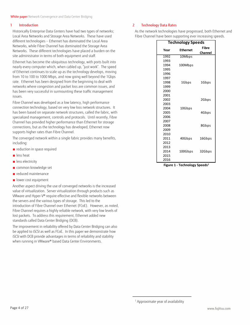
2 Technology Data Rates
As the network technologies have progressed, both Ethernet and
Fibre Channel have been supporting ever increasing speeds.
Figure 1 - Technology Speeds1
1 Approximate year of availability
Technology Speeds
Year EthernetFibre
Channel1992 10Mbps19931994 100Mbps1995199619971998 1Gbps 1Gbps1999200020012002 2Gbps20032004 10Gbps2005 4Gbps200620072008 8Gbps200920102011 40Gbps 16Gbps201220132014 100Gbps 32Gbps20152016
www.fujitsu.com
White paper Network Convergence and Data Center Bridging
Page 5 of 27
3 Ethernet Based SAN Protocols
3.1 Fibre Channel over Ethernet (FCoE)
FCoE was first standardized through INCITS from T11 FC-BB-5 in 2009 and published as ANSI/INCITS 462-2010 in May of 2010. It
encapsulates native Fibre Channel frames into Ethernet frames for
transmission over an Ethernet network. The encapsulation may be performed within the network access software stack or within
specialized Converged Network Adapters (CNAs). These cards
combine the functions of a Fibre Channel Host Bus Adapter (HBA)
with an Ethernet Network Interface Card (NIC) into a single adapter card. This reduces the number of slots required for adapters within
the servers.
As Fibre Channel assumes a highly reliable, very low loss network,
some extensions were defined to the Ethernet protocol to ensure that frames are not lost during periods of network congestion. These
extensions are collectively known as Data Center Bridging (DCB).
The primary focus of FCoE is within the Data Center for support of Storage Area Networks (SANs). With FCoE, reductions in cables,
interface cards, and switching devices are realized that result in
reductions in power and cooling costs. Both network traffic and
storage traffic can be consolidated using a single network. Network speeds of 10Gbps and above are utilized for the consolidated network
to ensure suitable storage access performance.
Fujitsu ETERNUS® DX S3 Storage Array products offer 10Gbps FCoE Channel Adapters for direct connection into Ethernet consolidated
fabrics in support of FCoE traffic.
3.2 Internet Small Computer System Interface (iSCSI)
ISCSI was first standardized by The Internet Society as RFC 3720 in
April 2004. RFC 7143 published in April 2014 by the Internet
Engineering Task Force (IETF) provides many updates and enhancements to the original standard for iSCSI. ISCSI provides a
transport protocol for communication of standard SCSI requests and
responses on top of the TCP layer in the Ethernet protocol stack. This technique made viable by the high speeds available within Ethernet
networks of 10Gbps and above, enables access to storage devices over
standard Ethernet networks. Unlike other SCSI transports, iSCSI opens
up greater distance capabilities. SCSI transports, such as Fibre Channel, IEEE-1394 (FireWire), IPI and Parallel SCSI all have very
limited distances for connections between the initiator and the target.
The TCP layer within the Ethernet protocol stack makes “best attempt”
delivery of the packets, even in times of congestion within the network, which permits iSCSI to operate in much less reliable network
environments than FCoE.
Because iSCSI can be software supported over a very low cost NIC, even Ethernet Interface ports built into many computers today, it has
become quite popular among the low cost portion of the marketplace.
It has not been that successful in attempts to utilize it within large
network environments, largely due to the impacts of recovery from lost packets.
Fujitsu ETERNUS DX S3 Storage Array products offer both 1Gbps and
10Gbps iSCSI Channel Adapters for direct connection into Ethernet consolidated networks in support of iSCSI traffic.
4 Data Center Bridging (DCB)
Data Center Bridging is made up of three different technologies that
work independently to provide enhanced features and attempt to eliminate any packet loss due to congestion within Ethernet. These
features were introduced into the Ethernet protocol to resolve the
packet loss due to congestion problem for support of FCoE, in order to provide a “lossless” Ethernet connection.
By employing DCB with iSCSI, more reliable iSCSI operation results as
well, so these features benefit both of the SAN protocols within the
Ethernet fabric.
4.1 Priority-based Flow Control (PFC)
Priority-based Flow Control, also called Per-Priority PAUSE, is defined in
the IEEE standard 802.1Qbb. PFC provides flow control on a Per-
Priority basis. It is used to inhibit transmission of data frames from one
or more of previously defined priorities for a specified period of time. The goal of this feature is to ensure zero loss under congestion within
DCB networks.
4.2 Enhanced Transmission Selection (ETS)
Enhanced Transmission Selection is defined in the IEEE standard
802.1Qaz. ETS defines priority groups for assigning a percentage of the available bandwidth on a link. In this context, available bandwidth
refers to the available link bandwidth after the traffic for the highest
priority has been serviced. The highest priority can use all the
bandwidth it needs, depending upon its traffic demand, and will always get what it needs, up to the full capability of the link.
4.3 Data Center Bridging Exchange (DCBX)
Data Center Bridging Exchange is defined in the IEEE standard
802.1Qaz. DCBX is a discovery and capability exchange protocol used
to exchange configuration information with a directly connected peer. It can also be used for detecting configuration errors and for
configuring a peer.
www.fujitsu.com
White paper Network Convergence and Data Center Bridging
Page 6 of 27
5 Best Practice Recommendations
5.1 Tradeoff between iSCSI and FCoE in Virtual Environments
Comparing the two convergence options: iSCSI and FCoE, each has its advantages.
The iSCSI protocol is based on TCP/IP which is the most widely implemented protocol and so its implementation is ubiquitous. In the Virtual environments it offers users flexibility on where the iSCSI initiator resides:
1. Under OS in the Virtual Machine (e.g. Using Microsoft® iSCSI initiator on Windows® VM)
2. Under Hypervisor (i.e. VMware iSCSI Initiator)
3. Under Hardware (e.g. Emulex® CNA).
Since iSCSI can be implemented using the basic 10Gbps NIC and does not impose any special requirement on the switches it has a lower cost.
FCoE on the other hand requires a special switch that implements Fibre Channel Forwarder (FCF) as well as DCB. Because DCB and therefore lossless Ethernet that is presented by DCB is required in FCoE, it offers more stable and predictable latency.
iSCSI, on the other hand, relies on TCP for recovery for packet losses, which can sometimes result in long latencies.
5.2 The use of iSCSI with DCB in Virtual Environments
The middle option which we focus on in this paper is to use iSCSI with DCB. This approach takes advantage of the reliability of lossless Ethernet offered by DCB, yet it retains some of the cost advantages of iSCSI.
In the case of VMware environments we used, it is necessary to use the hardware based iSCSI initiators in the CNA (such as Emulex OCe10102) because
DCB protocol is not supported directly in the virtual network environment. It is recommended for reason of stable operation to use the Hardware iSCSI option.
The following diagram (Figure 2) illustrates how the different layers implement the DCB function in the VMware iSCSI environment.
www.fujitsu.com
White paper Network Convergence and Data Center Bridging
Page 7 of 27
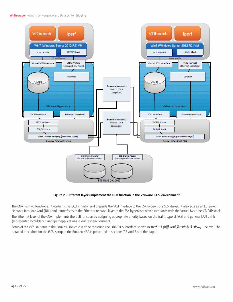
Figure 2 - Different layers implement the DCB function in the VMware iSCSI environment
The CNA has two functions: It contains the iSCSI initiator and presents the SCSI interface to the ESX hypervisor’s SCSI driver. It also acts as an Ethernet
Network Interface Card (NIC) and it interfaces to the Ethernet network layer in the ESX hypervisor which interfaces with the Virtual Machine’s TCP/IP stack.
The Ethernet layer of the CNA implements the DCB function by assigning appropriate priority based on the traffic type of iSCSI and general LAN traffic
(represented by VdBench and Iperf applications in our test environment).
Setup of the iSCSI initiator in the Emulex HBA card is done thorough the HBA BIOS interface shown in エラー! 参照元が見つかりません。 below. (The
detailed procedure for the iSCSI setup in the Emulex HBA is presented in sections 7.3 and 7.4 of the paper).
www.fujitsu.com
White paper Network Convergence and Data Center Bridging
Page 8 of 27
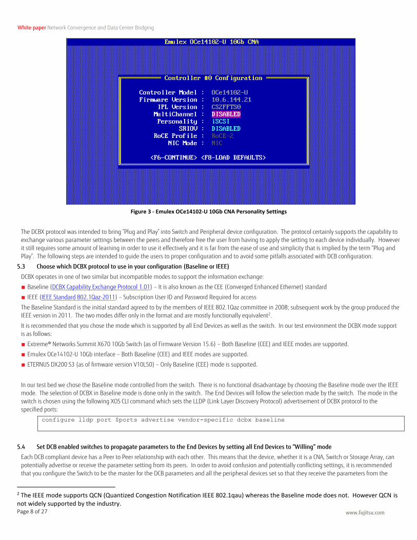
Figure 3 - Emulex OCe14102-U 10Gb CNA Personality Settings
The DCBX protocol was intended to bring ”Plug and Play” into Switch and Peripheral device configuration. The protocol certainly supports the capability to exchange various parameter settings between the peers and therefore free the user from having to apply the setting to each device individually. However
it still requires some amount of learning in order to use it effectively and it is far from the ease of use and simplicity that is implied by the term “Plug and
Play”. The following steps are intended to guide the users to proper configuration and to avoid some pitfalls associated with DCB configuration.
5.3 Choose which DCBX protocol to use in your configuration (Baseline or IEEE)
DCBX operates in one of two similar but incompatible modes to support the information exchange:
■ Baseline (DCBX Capability Exchange Protocol 1.01) – It is also known as the CEE (Converged Enhanced Ethernet) standard
■ IEEE (IEEE Standard 802.1Qaz-2011) – Subscription User ID and Password Required for access
The Baseline Standard is the initial standard agreed to by the members of IEEE 802.1Qaz committee in 2008; subsequent work by the group produced the IEEE version in 2011. The two modes differ only in the format and are mostly functionally equivalent2.
It is recommended that you chose the mode which is supported by all End Devices as well as the switch. In our test environment the DCBX mode support
is as follows:
■ Extreme® Networks Summit X670 10Gb Switch (as of Firmware Version 15.6) – Both Baseline (CEE) and IEEE modes are supported.
■ Emulex OCe14102-U 10Gb interface – Both Baseline (CEE) and IEEE modes are supported.
■ ETERNUS DX200 S3 (as of firmware version V10L50) – Only Baseline (CEE) mode is supported.
In our test bed we chose the Baseline mode controlled from the switch. There is no functional disadvantage by choosing the Baseline mode over the IEEE mode. The selection of DCBX in Baseline mode is done only in the switch. The End Devices will follow the selection made by the switch. The mode in the
switch is chosen using the following XOS CLI command which sets the LLDP (Link Layer Discovery Protocol) advertisement of DCBX protocol to the
specified ports:
configure lldp port $ports advertise vendor-specific dcbx baseline
5.4 Set DCB enabled switches to propagate parameters to the End Devices by setting all End Devices to “Willing” mode
Each DCB compliant device has a Peer to Peer relationship with each other. This means that the device, whether it is a CNA, Switch or Storage Array, can
potentially advertise or receive the parameter setting from its peers. In order to avoid confusion and potentially conflicting settings, it is recommended
that you configure the Switch to be the master for the DCB parameters and all the peripheral devices set so that they receive the parameters from the
2 The IEEE mode supports QCN (Quantized Congestion Notification IEEE 802.1qau) whereas the Baseline mode does not. However QCN is not widely supported by the industry.
www.fujitsu.com
White paper Network Convergence and Data Center Bridging
Page 9 of 27
Switch.
DCB protocol has a mode called “Willing” which means the device will accept the parameter setting from the Peer. All the Peripheral Devices meaning CNA
in the servers and the storage arrays should be set to the “Willing” mode using the following methods:
■ The Emulex CNA does not have an explicit setting for DCB modes. It is set to “Willing” mode by default
■ ETERNUS DX200 S3 (as of firmware version V10L50-0000) – The ETERNUS DX200 S3 model’s iSCSI CA ports are always configured in “Willing” mode so there is no need to make any changes.
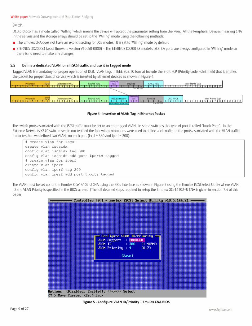
5.5 Define a dedicated VLAN for all iSCSI traffic and use it in Tagged mode
Tagged VLAN is mandatory for proper operation of DCB. VLAN tags in IEEE 802.1Q format include the 3-bit PCP (Priority Code Point) field that identifies
the packet for proper class of service which is inserted by Ethernet devices as shown in Figure 4.
Figure 4 - Insertion of VLAN Tag in Ethernet Packet
The switch ports associated with the iSCSI traffic must be set to accept tagged VLAN. In some switches this type of port is called “Trunk Ports”. In the
Extreme Networks X670 switch used in our testbed the following commands were used to define and configure the ports associated with the VLAN traffic.
In our testbed we defined two VLANs on each port (iscsi = 380 and iperf = 200):
# create vlan for iscsi
create vlan iscsidx
config vlan iscsidx tag 380
config vlan iscsidx add port $ports tagged
# create vlan for iperf
create vlan iperf
config vlan iperf tag 200
config vlan iperf add port $ports tagged
The VLAN must be set up for the Emulex OCe14102-U CNA using the BIOs interface as shown in Figure 5 using the Emulex iSCSI Select Utility where VLAN
ID and VLAN Priority is specified in the BIOS screen. (The full detailed steps required to setup the Emulex OCe14102–U CNA is given in section 7.4 of this paper)
Figure 5 - Configure VLAN ID/Priority – Emulex CNA BIOS
www.fujitsu.com
White paper Network Convergence and Data Center Bridging
Page 10 of 27
5.6 Set up the Priority for ETS (Enhanced Transmission Selection) feature using weighted round robin algorithm
ETS (Enhanced Transmission Selection) allows the total bandwidth to be divided according to the Priority Groups (as defined in the DCBX Baseline
specification).
There are two types of priority allocation algorithm: strict-priority and weighted round robin.
In the Extreme Networks Switch there are eight priority classes that are encoded in 3 different methods described below:
■ 3-bit PCP (Priority Control Point) or Dot1P class – This is the 3-bit code in the VLAN PCP tag – There are eight Dot1P classes ranging from 0 to 7.
■ PG Priority Group – This is a Priority Group number (PG#) which also ranges from 0 to 7.
■ QoS Profile – This is the Quality Service Group number which is assigned internally in the Extreme Networks Switch – This ranges from qp1 to qp8.
The QoS Profile number is always one greater than the PG number (i.e. QoS# = PG# +1; so, qp5 has a PG# of 4).
In order to keep the coding simple to remember, it is recommended that QoS Profile number is always mapped to the Dot1P class + 1. All of the numbers
hold the same relationship (qp5 maps to PG# 4 which maps to PCP# 4).
Strict Priority algorithm sets strict guaranteed minimum and maximum limits for each QoS Group. For example, command “configure qosprofile
qp5 minbw 10 maxbw 80 ports all” will reserve 10% of the bandwidth to qp5 and will place a hard limit of 80%.
configure dot1p type 4 qp5
configure qosscheduler weighted-round-robin
configure qosprofile qp1 weight 1
configure qosprofile qp5 weight 8
5.7 Enable PFC (Priority Flow Control) for the iSCSI traffic class
PFC should be enabled for iSCSI traffic. This enables lossless transmission which will greatly improve the iSCSI stability by minimizing the packet loss. (Packet loss results in long timeouts that can hang the iSCSI stream for as long as 10 seconds).
The following XOS CLI commands are executed to enable PFC for iSCSI, note that QoS Number is used for rx-pause and Dot1P number is used for tx-pause:
docli enable flow-control rx-pause qosprofile qp5 ports $ports
docli enable flow-control tx-pause priority 4 ports $ports
5.8 Wait for the DCBX protocol setting to be transmitted properly and check the status on both the CNA and the Switch
It is recommended that after the commands to enable DCB are executed, issue a command to disable the port on the switch to create link down condition
for an instant. This action speeds up the propagation of the new configuration from the switch to its peers.
DCBX protocol does not have an explicit acknowledgement handshake mechanism. When a command is executed to change the local configuration, the
new configuration data is advertised to the peer though the periodic lldp multicasts. The peer which receives the multicast will update its own local
configuration and then send out updated status in its next multicast. The problem is that the multicasts are only performed periodically (typically every
30 seconds) so it takes about 30 seconds to get to the point where both peers recognize that they are in sync which is why it takes time before the user can verify that the configuration is correct. The members of the IEEE group recognized this problem and added a feature to speed up the frequency of the
multicasts to every 1 second immediately after the Link-up event3.
The following sequence of Extreme Networks Switch CLI commands illustrates this point:
# $port contain the list of port numbers
enable lldp ports $ports ;# Enable LLDP multicasting on the selected ports
configure lldp port $ports advertise vendor-specific dcbx baseline ;# chose DCBX baseline
configure lldp port $ports dcbx add application name iscsi priority 4 ;# enable iscsi
application TLV
disable ports $ports ;# link down
enable ports $ports ;# and link up to speed up LLDP multicasting frequency
The DCBX status can be checked by issuing following command on the Extreme Networks Switch:
* x670-top.1 # show lldp dcbx baseline
=============================================
Baseline DCBX TLV Status:
Port Control PG PFC App
=============================================
10 OK OK OK OK
40 OK OK OK OK
44 OK OK OK OK
=============================================
Control - Control TLV
3 The problem and its solution is documented in “section 2.3.1.1 Fast initial LLDP Transmissions” of the DCBX Capability Exchange Protocol 1.01.
www.fujitsu.com
White paper Network Convergence and Data Center Bridging
Page 11 of 27
PG - Priority Group TLV
PFC - Priority-Based Flow Control TLV
App - Application Configuration TLV
The above status shows that ports 10, 40 and 44 (connected to ETERNUS DX200 S3 CA port, and ESXi Server Emulex CNA ports respectively) have properly
exchanged the DCBX TLV (Type, Length, Value data structure).
5.9 Set ETERNUS® Host Response to use Send Target (single response mode).
This is important especially when scripting is used to achieve predictable response during iSCSI discovery. ETERNUS DX arrays respond to iSCSI “Send Target”
inquiry by responding with target ports for all the iSCSI CA ports. This is fine for interactive use but in some cases this results in target response with invalid target information which causes timeout delay when discovery is being executed in PowerShell Script. So the following CLI command is executed
to define a special iSCSI_DCB Host response so that the array will respond with single target information:
set host-response -host-response-number 3 -name iSCSI_DCB -iscsi-disc-rsp port
www.fujitsu.com
White paper Network Convergence and Data Center Bridging
Page 12 of 27
6 Lab Testing
6.1 Test Configurations
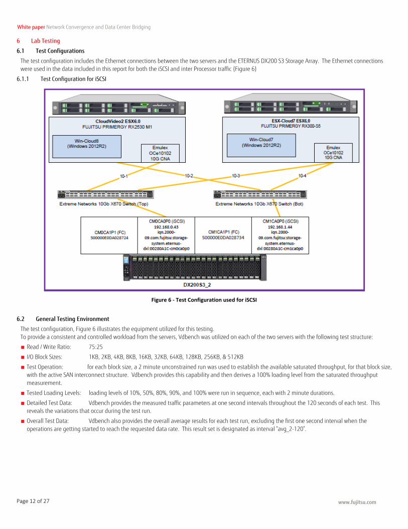
The test configuration includes the Ethernet connections between the two servers and the ETERNUS DX200 S3 Storage Array. The Ethernet connections were used in the data included in this report for both the iSCSI and inter Processor traffic (Figure 6)
6.1.1 Test Configuration for iSCSI
Figure 6 - Test Configuration used for iSCSI
6.2 General Testing Environment
The test configuration, Figure 6 illustrates the equipment utilized for this testing.
To provide a consistent and controlled workload from the servers, Vdbench was utilized on each of the two servers with the following test structure:
■ Read / Write Ratio: 75:25
■ I/O Block Sizes: 1KB, 2KB, 4KB, 8KB, 16KB, 32KB, 64KB, 128KB, 256KB, & 512KB
■ Test Operation: for each block size, a 2 minute unconstrained run was used to establish the available saturated throughput, for that block size, with the active SAN interconnect structure. Vdbench provides this capability and then derives a 100% loading level from the saturated throughput
measurement.
■ Tested Loading Levels: loading levels of 10%, 50%, 80%, 90%, and 100% were run in sequence, each with 2 minute durations.
■ Detailed Test Data: Vdbench provides the measured traffic parameters at one second intervals throughout the 120 seconds of each test. This reveals the variations that occur during the test run.
■ Overall Test Data: Vdbench also provides the overall average results for each test run, excluding the first one second interval when the
operations are getting started to reach the requested data rate. This result set is designated as interval “avg_2-120”.

www.fujitsu.com
White paper Network Convergence and Data Center Bridging
Page 13 of 27
6.2.1 Software Drivers used in the testing
For completeness in documenting the test environment, the following specific versions were used in the testing reported within this paper:
■ Vdbench Toolkit (version 5.0403)
http://www.oracle.com/technetwork/server-storage/vdbench-downloads-1901681.html
■ Extreme Networks Summit X670 Series XtremeOS Release 15.4 http://extrcdn.extremenetworks.com/wp-content/uploads/2014/01/EXOS_Command_Reference_Guide_15_4.pdf
http://extrcdn.extremenetworks.com/wp-content/uploads/2014/01/EXOS_Concepts_Guide_15_4.pdf
■ Emulex OCe14102 10G CNA and OneCommand Manager for VMware vCenter Server http://sp.ts.fujitsu.com/dmsp/Publications/public/ds-py-pcna-ep-OCe14102.pdf
http://www.avagotech.com/products/server-storage/fibre-channel-host-bus-adapters/onecommand-manager-vmware
■ Cygwin Package for Windows 2.2.1 (includes Expect 5.45)
http://cygwin.com/install.html
■ Fujitsu ETERNUS DX200 S3 Firmware version V10L50-0000
■ Interference Ethernet Traffic – use of iperf
An open source network testing tool, called iperf, was used to introduce TCP/IP traffic on the network between the two servers, which interferes with the
iSCSI traffic and reduces the throughput. Iperf can provide both TCP and UDP types of traffic, which were used in this testing environment. Both TCP and UDP iperf servers were defined on each of the two host systems (win7 and win8). Iperf clients were set up to request traffic from the other system, using
ports 5001 and 5002.
The commands for setting up the Server instances of iperf were:
■ $IPERF –s P $pfactorTCP –i 1 –B $serverIP –f m –w 128k –p 5001 #(command to start TCP server)
■ $IPERF – s –u –P $pfactorUDP –i 1 –B $serverIP –p 5002 –l 1500.0B –f m #(command to start UDP server)
where “pfactorTCP” and “pfactorUDP” provide the number of parallel streams generated
The commands for setting up the Client instances of iperf were:
■ $IPERF –c $serverIP –P $pfactorTCP –d –i 1 –p 5001 –w 128k –M 1.0k –l 9.0m –f m –t $duration #(command to start TCP client)
■ $IPERF –c $serverIP – u –P $pfactorUDP –d –i 1 –p 5002 –w 400.0m –l 1500.0B –f m –b 2000.0M –t (duration –T 1 #(command to start UDP client)
The client processes were set to run for a random duration (20-26 seconds) then to sleep for a random time (1-3 seconds) and repeat. An associated GUI,
iperf, was used to determine the appropriate parameter settings for the interference workload included in the test execution script.
6.3 Performance Data Used for Evaluation
6.3.1 Selected Vdbench Measured Elements
There is a large amount of data collected by Vdbench during the test operations and selected portions have been used to provide the evaluations and gain insight into the behavior of DCB within an iSCSI traffic environment. Selected elements include:
■ tod: provides the time of day at which each test run was completed
■ Run: provides the identification of each run, such as “run1_(10%)” or “run1_(100%)”
■ interval: provides the number of the test interval ranging from 1 to 120, plus “avg_2-120”
■ reqrate: provides the requested data rate (IOPs) that Vdbench is attempting to maintain
■ rate: provides the measured data rate in IOPs for the interval
■ MB/sec: provides the measured data throughput in MB/s for the interval
■ bytes/io: provides the block size for the I/Os issued in the interval
■ resp: provides the measured Response Time in milliseconds for the interval
■ resp_std: provides the measured Standard Deviation for the Response Times within the interval
6.3.2 Collected Vdbench Data Sets
Two different sets of Vdbench data were collected for each of the test runs:
■ One set provides a broad look at the test runs through the Average IOPs and Average MB/s at each of the measured block sizes and at each of the
loading levels. These results are reported in a following section.
■ The other set provides a detailed look at selected block sizes (4KB, 8KB, 64KB, & 256KB) for the 100% loading level. The data from the Vdbench results
on the two servers are brought together in workbooks with sheets for each block size. Charts are provided as well as overall statistics for each of the selected block sizes. These results provide insight into the balance of the loading between the two servers and are reported in a following section.
www.fujitsu.com
White paper Network Convergence and Data Center Bridging
Page 14 of 27
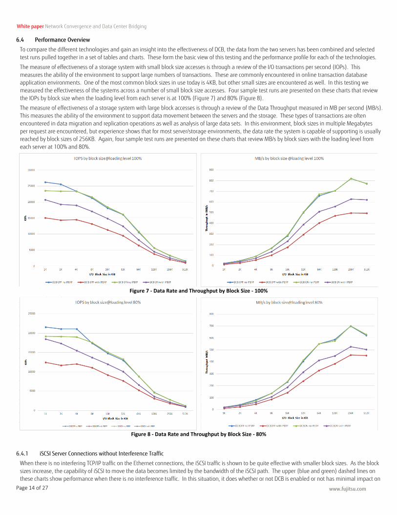
6.4 Performance Overview
To compare the different technologies and gain an insight into the effectiveness of DCB, the data from the two servers has been combined and selected
test runs pulled together in a set of tables and charts. These form the basic view of this testing and the performance profile for each of the technologies.
The measure of effectiveness of a storage system with small block size accesses is through a review of the I/O transactions per second (IOPs). This
measures the ability of the environment to support large numbers of transactions. These are commonly encountered in online transaction database application environments. One of the most common block sizes in use today is 4KB, but other small sizes are encountered as well. In this testing we
measured the effectiveness of the systems across a number of small block size accesses. Four sample test runs are presented on these charts that review
the IOPs by block size when the loading level from each server is at 100% (Figure 7) and 80% (Figure 8).
The measure of effectiveness of a storage system with large block accesses is through a review of the Data Throughput measured in MB per second (MB/s).
This measures the ability of the environment to support data movement between the servers and the storage. These types of transactions are often
encountered in data migration and replication operations as well as analysis of large data sets. In this environment, block sizes in multiple Megabytes
per request are encountered, but experience shows that for most server/storage environments, the data rate the system is capable of supporting is usually reached by block sizes of 256KB. Again, four sample test runs are presented on these charts that review MB/s by block sizes with the loading level from
each server at 100% and 80%.
Figure 7 - Data Rate and Throughput by Block Size - 100%
Figure 8 - Data Rate and Throughput by Block Size - 80%
6.4.1 iSCSI Server Connections without Interference Traffic
When there is no interfering TCP/IP traffic on the Ethernet connections, the iSCSI traffic is shown to be quite effective with smaller block sizes. As the block
sizes increase, the capability of iSCSI to move the data becomes limited by the bandwidth of the iSCSI path. The upper (blue and green) dashed lines on these charts show performance when there is no interference traffic. In this situation, it does whether or not DCB is enabled or not has minimal impact on
www.fujitsu.com
White paper Network Convergence and Data Center Bridging
Page 15 of 27
the performance level.
6.4.2 iSCSI Server Connections with Interference Traffic, DCB not Enabled
When the iSCSI environment has competing TCP/IP traffic on the Ethernet connections, the iSCSI traffic can be severely impacted. Both the small block and large block data moving capabilities are reduced significantly. The lower (red) line on the above charts shows the clear drop in performance across all
access block sizes when there is interfering network traffic and DCB is not enabled.
6.4.3 iSCSI Server Connections with Interference Traffic and DCB Enabled
DCB provides the Ethernet network environment the means of providing preferential network bandwidth to a chosen subset of the traffic. In this
environment, the iSCSI traffic can be assured sufficient network bandwidth to provide reasonable response times to the user demands for storage access. The curves in yellow on the above charts show the improved performance across all block sizes when DCB is enabled and there is interfering traffic on the
network. It is quite clear that use of DCB, where network preference is given to the iSCSI traffic, the storage access performance is significantly improved.
www.fujitsu.com
White paper Network Convergence and Data Center Bridging
Page 16 of 27
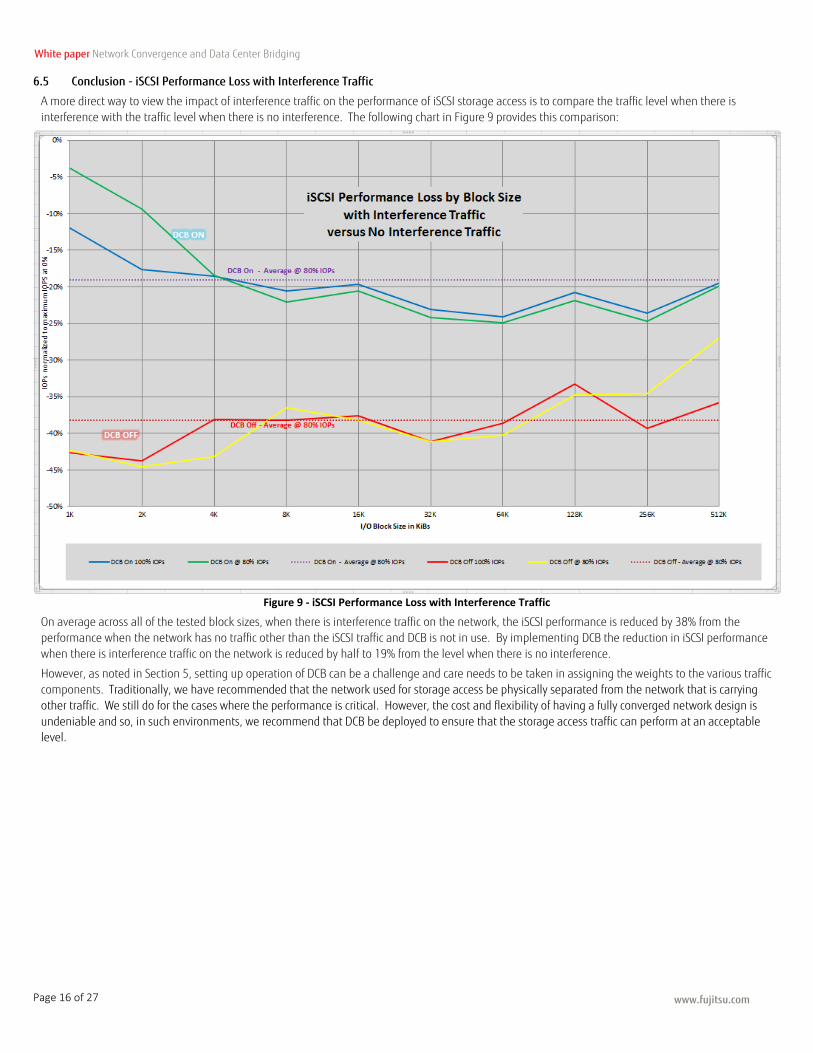
6.5 Conclusion - iSCSI Performance Loss with Interference Traffic
A more direct way to view the impact of interference traffic on the performance of iSCSI storage access is to compare the traffic level when there is
interference with the traffic level when there is no interference. The following chart in Figure 9 provides this comparison:
Figure 9 - iSCSI Performance Loss with Interference Traffic
On average across all of the tested block sizes, when there is interference traffic on the network, the iSCSI performance is reduced by 38% from the
performance when the network has no traffic other than the iSCSI traffic and DCB is not in use. By implementing DCB the reduction in iSCSI performance
when there is interference traffic on the network is reduced by half to 19% from the level when there is no interference.
However, as noted in Section 5, setting up operation of DCB can be a challenge and care needs to be taken in assigning the weights to the various traffic
components. Traditionally, we have recommended that the network used for storage access be physically separated from the network that is carrying
other traffic. We still do for the cases where the performance is critical. However, the cost and flexibility of having a fully converged network design is
undeniable and so, in such environments, we recommend that DCB be deployed to ensure that the storage access traffic can perform at an acceptable level.
www.fujitsu.com
White paper Network Convergence and Data Center Bridging
Page 17 of 27
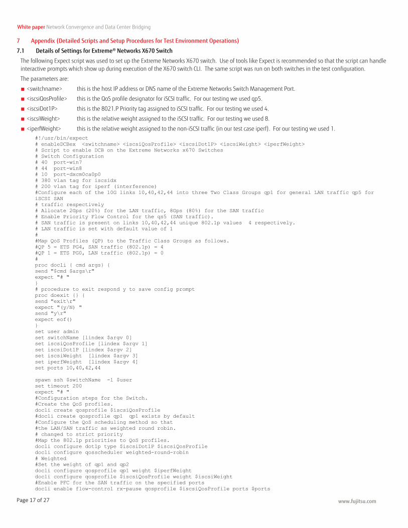
7 Appendix (Detailed Scripts and Setup Procedures for Test Environment Operations)
7.1 Details of Settings for Extreme® Networks X670 Switch
The following Expect script was used to set up the Extreme Networks X670 switch. Use of tools like Expect is recommended so that the script can handle interactive prompts which show up during execution of the X670 switch CLI. The same script was run on both switches in the test configuration.
The parameters are:
■ <switchname> this is the host IP address or DNS name of the Extreme Networks Switch Management Port.
■ <iscsiQosProfile> this is the QoS profile designator for iSCSI traffic. For our testing we used qp5.
■ <iscsiDot1P> this is the 8021.P Priority tag assigned to iSCSI traffic. For our testing we used 4.
■ <iscsiWeight> this is the relative weight assigned to the iSCSI traffic. For our testing we used 8.
■ <iperfWeight> this is the relative weight assigned to the non-iSCSI traffic (in our test case iperf). For our testing we used 1.
#!/usr/bin/expect
# enableDCBex <switchname> <iscsiQosProfile> <iscsiDot1P> <iscsiWeight> <iperfWeight>
# Script to enable DCB on the Extreme Networks x670 Switches
# Switch Configuration
# 40 port-win7
# 44 port-win8
# 10 port-dxcm0ca0p0
# 380 vlan tag for iscsidx
# 200 vlan tag for iperf (interference)
#Configure each of the 10G links 10,40,42,44 into three Two Class Groups qp1 for general LAN traffic qp5 for
iSCSI SAN
# traffic respectively
# Allocate 2Gps (20%) for the LAN traffic, 8Gps (80%) for the SAN traffic
# Enable Priority Flow Control for the qs5 (SAN traffic).
# SAN traffic is present on links 10,40,42,44 unique 802.1p values 4 respectively.
# LAN traffic is set with default value of 1
#
#Map QoS Profiles (QP) to the Traffic Class Groups as follows.
#QP 5 = ETS PG4, SAN traffic (802.1p) = 4
#QP 1 = ETS PG0, LAN traffic (802.1p) = 0
#
proc docli { cmd args} {
send "$cmd $args\r"
expect "# "
}
# procedure to exit respond y to save config prompt
proc doexit {} {
send "exit\r"
expect "(y/N) "
send "y\r"
expect eof()
}
set user admin
set switchName [lindex $argv 0]
set iscsiQosProfile [lindex $argv 1]
set iscsiDot1P [lindex $argv 2]
set iscsiWeight [lindex $argv 3]
set iperfWeight [lindex $argv 4]
set ports 10,40,42,44
spawn ssh $switchName -l $user
set timeout 200
expect "# "
#Configuration steps for the Switch.
#Create the QoS profiles.
docli create qosprofile $iscsiQosProfile
#docli create qosprofile qp1 qp1 exists by default
#Configure the QoS scheduling method so that
#the LAN/SAN traffic as weighted round robin.
# changed to strict priority
#Map the 802.1p priorities to QoS profiles.
docli configure dot1p type $iscsiDot1P $iscsiQosProfile
docli configure qosscheduler weighted-round-robin
# Weighted
#Set the weight of qp1 and qp2
docli configure qosprofile qp1 weight $iperfWeight
docli configure qosprofile $iscsiQosProfile weight $iscsiWeight
#Enable PFC for the SAN traffic on the specified ports
docli enable flow-control rx-pause qosprofile $iscsiQosProfile ports $ports

www.fujitsu.com
White paper Network Convergence and Data Center Bridging
Page 18 of 27
docli enable flow-control tx-pause priority $iscsiDot1P ports $ports
# create vlan for iscsi
docli create vlan iscsidx
docli config vlan iscsidx tag 380
docli config vlan iscsidx add port $ports tagged
docli create vlan iperf
docli config vlan iperf tag 200
docli config vlan iperf add port $ports tagged
docli create vlan iscsicna
docli config vlan iscsicna tag 350
docli config vlan iscsicna add port $ports tagged
# advertise dcbx support through lldp with iscsi application
docli enable lldp ports $ports
docli configure lldp port $ports advertise vendor-specific dcbx baseline
docli configure lldp port $ports dcbx add application name iscsi priority $iscsiDot1P
# link down for an instance to reflect the change
docli disable ports $ports
docli enable ports $ports
# show the current dcbx state
docli show lldp port $ports dcbx
## Logout ##
Doexit
7.2 Details of OneCommand Manager for VMware vCenter
The following screenshots are for OneCommand Manger for VMware vCenter related to DCB.
Emulex OneCommand tab will be available after the installation of Emulex OneCommand Manager for VMware vCenter.
Select the Port of iSCSI HBA which is used for DCB in Emulex Device Management window to show the information as figure 9
Figure 10 - Emulex Device Management Window
Select the Configure DCB button and then DCB Configuration window will be displayed as Figure 10.
www.fujitsu.com
White paper Network Convergence and Data Center Bridging
Page 19 of 27
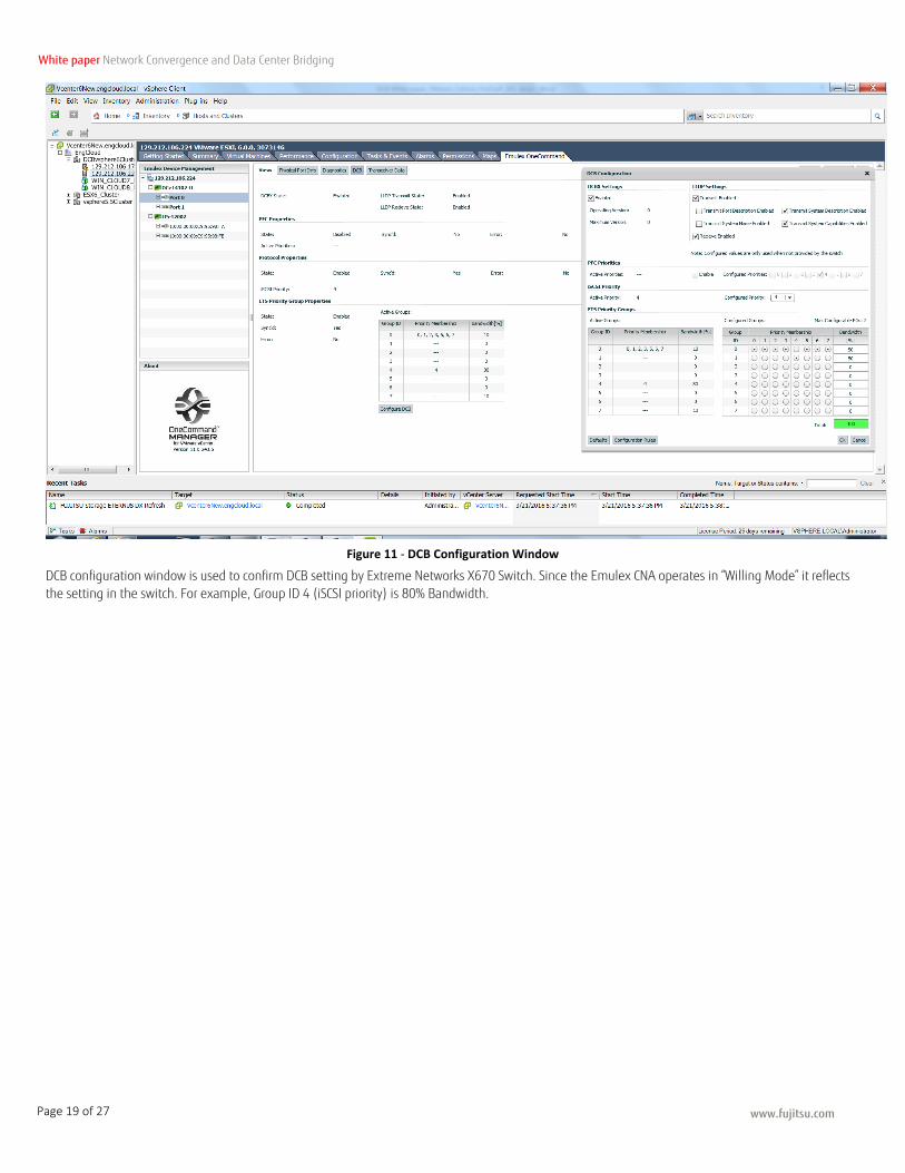
Figure 11 - DCB Configuration Window
DCB configuration window is used to confirm DCB setting by Extreme Networks X670 Switch. Since the Emulex CNA operates in “Willing Mode” it reflects
the setting in the switch. For example, Group ID 4 (iSCSI priority) is 80% Bandwidth.
www.fujitsu.com
White paper Network Convergence and Data Center Bridging
Page 20 of 27
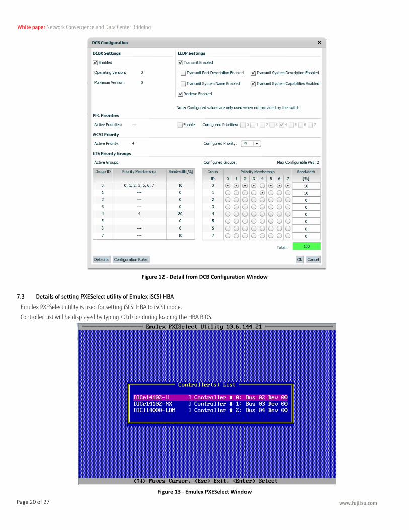
Figure 12 - Detail from DCB Configuration Window
7.3 Details of setting PXESelect utility of Emulex iSCSI HBA
Emulex PXESelect utility is used for setting iSCSI HBA to iSCSI mode.
Controller List will be displayed by typing <Ctrl+p> during loading the HBA BIOS.
Figure 13 - Emulex PXESelect Window
www.fujitsu.com
White paper Network Convergence and Data Center Bridging
Page 21 of 27
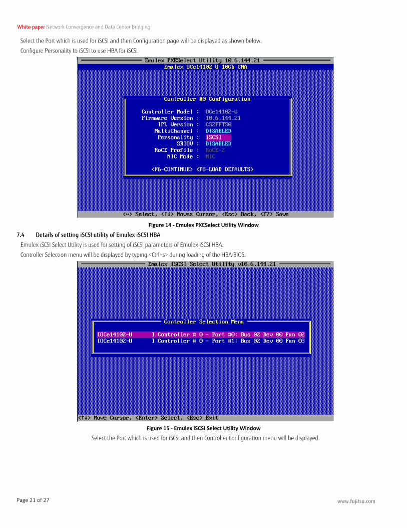
Select the Port which is used for iSCSI and then Configuration page will be displayed as shown below.
Configure Personality to iSCSI to use HBA for iSCSI
Figure 14 - Emulex PXESelect Utility Window
7.4 Details of setting iSCSI utility of Emulex iSCSI HBA
Emulex iSCSI Select Utility is used for setting of iSCSI parameters of Emulex iSCSI HBA.
Controller Selection menu will be displayed by typing <Ctrl+s> during loading of the HBA BIOS.
Figure 15 - Emulex iSCSI Select Utility Window
Select the Port which is used for iSCSI and then Controller Configuration menu will be displayed.

www.fujitsu.com
White paper Network Convergence and Data Center Bridging
Page 22 of 27
.
Figure 16 - Emulex iSCSI Select Utility Window (Controller Properties)
7.4.1 Set the iSCSI Initiator Name at Controller Properties page
Select Controller Properties and then following window will be displayed.
Figure 17 - Emulex iSCSI Select Utility Window (Emulex 0cel1402-U 10Gb C)
Enter iSCSI Initiator Name.
7.4.2 Set IP Address and VLAN ID/Priority at Network Configuration page
Select Network Configuration and then following window will be displayed.
www.fujitsu.com
White paper Network Convergence and Data Center Bridging
Page 23 of 27
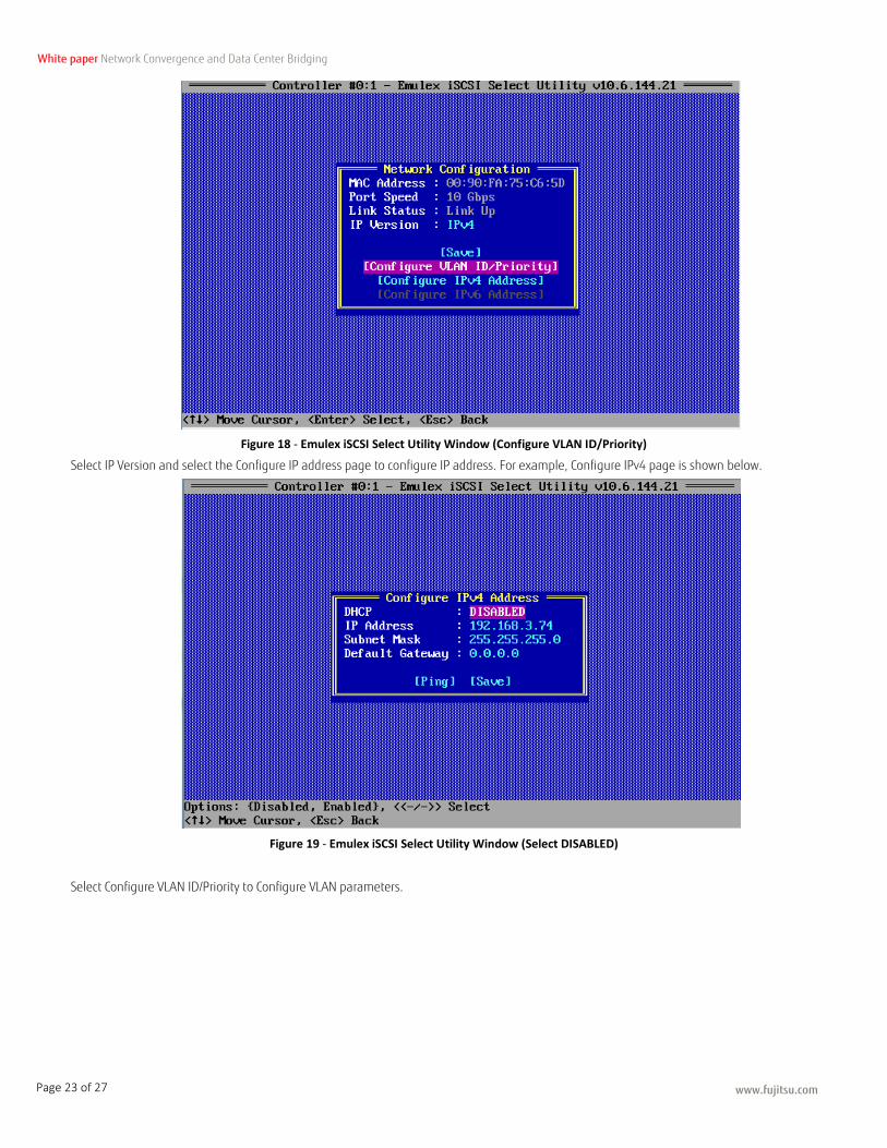
Figure 18 - Emulex iSCSI Select Utility Window (Configure VLAN ID/Priority)
Select IP Version and select the Configure IP address page to configure IP address. For example, Configure IPv4 page is shown below.
Figure 19 - Emulex iSCSI Select Utility Window (Select DISABLED)
Select Configure VLAN ID/Priority to Configure VLAN parameters.
www.fujitsu.com
White paper Network Convergence and Data Center Bridging
Page 24 of 27
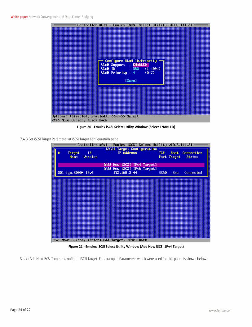
Figure 20 - Emulex iSCSI Select Utility Window (Select ENABLED)
7.4.3 Set iSCSI Target Parameter at iSCSI Target Configuration page
Figure 21 - Emulex iSCSI Select Utility Window (Add New iSCSI 1Pv4 Target)
Select Add New iSCSI Target to configure iSCSI Target. For example, Parameters which were used for this paper is shown below.
www.fujitsu.com
White paper Network Convergence and Data Center Bridging
Page 25 of 27
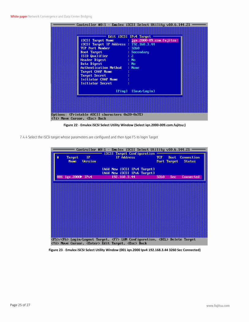
Figure 22 - Emulex iSCSI Select Utility Window (Select iqn.2000-009.com.fujitsu:)
7.4.4 Select the iSCSI target whose parameters are configured and then type F5 to login Target
Figure 23 - Emulex iSCSI Select Utility Window (001 iqn.2000 Ipv4 192.168.3.44 3260 Sec Connected)
www.fujitsu.com
White paper Network Convergence and Data Center Bridging
Page 26 of 27
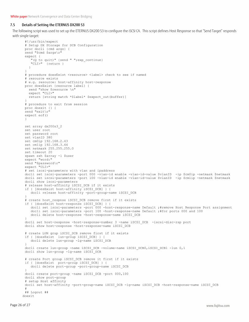
7.5 Details of Setting the ETERNUS DX200 S3
The following script was used to set up the ETERNUS DX200 S3 to configure the iSCSI CA. This script defines Host Response so that “Send Target” responds
with single target:
#!/usr/bin/expect
# Setup DX Storage for DCB Configuration
proc docli {cmd args} {
send "$cmd $args\r"
expect {
"(Q to quit)" {send " ";exp_continue}
"CLI>" {return }
}
}
# procedure doesExist <resource> <label> check to see if named
# resource exists
# e.g. resource: host-affinity host-response
proc doesExist {resource label} {
send "show $resource \n"
expect "CLI>"
return [string match *$label* $expect_out(buffer)]
}
# procedure to exit from session
proc doexit {} {
send "exit\r"
expect eof()
}
set array dx200s3_2
set user root
set password root
set vlanID 380
set cm0ip 192.168.2.43
set cm1ip 192.168.3.44
set netmask 255.255.255.0
set timeout 20
spawn ssh $array -l $user
expect "word:"
send "$password\r"
expect "CLI>"
# set iscsi-parameters with vlan and ipaddress
docli set iscsi-parameters -port 000 -vlan-id enable -vlan-id-value $vlanID -ip $cm0ip -netmask $netmask
docli set iscsi-parameters -port 100 -vlan-id enable -vlan-id-value $vlanID -ip $cm1ip -netmask $netmask
docli show iscsi-parameters
# release host-affinity iSCSI_DCB if it exists
if { [doesExist host-affinity iSCSI_DCB] } {
docli release host-affinity -port-group-name iSCSI_DCB
}
# create host_respnse iSCSI_DCB remove first if it exists
if { [doesExist host-response iSCSI_DCB] } {
docli set iscsi-parameters -port 000 -host-response-name Default ;#remove Host Response Port assignment
docli set iscsi-parameters -port 100 -host-response-name Default ;#for ports 000 and 100
docli delete host-response -host-response-name iSCSI_DCB
}
docli set host-response -host-response-number 3 -name iSCSI_DCB -iscsi-disc-rsp port
docli show host-response -host-response-name iSCSI_DCB
# create LUN grup iSCSI_DCB remove first if it exists
if { [doesExist lun-group iSCSI_DCB] } {
docli delete lun-group -lg-name iSCSI_DCB
}
docli create lun-group -name iSCSI_DCB -volume-name iSCSI_DCB0,iSCSI_DCB1 -lun 0,1
docli show lun-group -lg-name iSCSI_DCB
# create Port group iSCSI_DCB remove it first if it exists
if { [doesExist port-group iSCSI_DCB] } {
docli delete port-group -port-group-name iSCSI_DCB
}
docli create port-group -name iSCSI_DCB -port 000,100
docli show port-group
# setup Host affinity
docli set host-affinity -port-group-name iSCSI_DCB -lg-name iSCSI_DCB -host-response-name iSCSI_DCB
#
## Logout ##
doexit
www.fujitsu.com
White paper Network Convergence and Data Center Bridging
Page 27 of 27
About Fujitsu Americas Fujitsu America, Inc. is the parent and/or management company of a group of Fujitsu-owned companies operating in North, Central and South America and Caribbean, dedicated to delivering the full range of Fujitsu products, solutions and services in ICT to our customers in the Western Hemisphere. These companies are collectively referred to as Fujitsu Americas. Fujitsu enables clients to meet their business objectives through integrated offerings and solutions, including consulting, systems integration, managed services, outsourcing and cloud services for infrastructure, platforms and applications; data center and field services; and server, storage, software and mobile/tablet technologies. For more information, please visit: http://solutions.us.fujitsu.com/ and http://twitter.com/fujitsuamerica FUJITSU AMERICA, INC. Address: 1250 East Arques Avenue Sunnyvale, CA 94085-3470, U.S.A. Telephone: 800 831 3183 or 408 746 6000 Website: http://solutions.us.fujitsu.com Contact Form: http://solutions.us.fujitsu.com/contact
Have a question? Email us at: [email protected] Fujitsu, the Fujitsu logo, ETERNUS and “shaping tomorrow with you" are trademarks or registered trademarks of Fujitsu Limited in the United States and other countries. VMware is a trademark or registered trademark of VMware, Inc. in the United States and other countries. Emulex is a trademark or registered trademark of Avago Technologies, in the United States and other countries. Extreme is a trademark or registered trademark of Extreme Networks, Inc. in the United States and other countries. Windows and Hyper-V are trademarks or registered trademarks of Microsoft Corporation in the United States and other countries. Extreme Networks is a trademark or registered trademark of Extreme Networks, Inc. in the United States and other countries. All other trademarks referenced herein are the property of their respective owners.
The statements provided herein are for informational purposes only and may be amended or altered by Fujitsu America, Inc. without notice or liability. Product
description data represents Fujitsu design objectives and is provided for comparative purposes; actual results may vary based on a variety of factors. Specifications are
subject to change without notice.
Copyright© 2016 Fujitsu America, Inc. All rights reserved. FPC65-7506-02 04/16. 16.0316