white paper digital wireless - sennheiser
TRANSCRIPT

Page 1 of 29 | WHITE PAPER Digital Wireless Microphones | 10/2013
WHITE PAPER
Digital Wireless Microphones
Page 2 of 29 | WHITEPAPER Digital Wireless Microphones | 10/2013
Moving from analog to digital .......................................................................................................... 3
Professional customer requirements ............................................................................................... 7
Analog transmission .......................................................................................................................... 9
Digital transmission without data compression .......................................................................... 10
Digital transmission with data compression ................................................................................ 11
Multi-channel capability .................................................................................................................. 12
Audio quality ..................................................................................................................................... 14
Latency ............................................................................................................................................... 19
Operating time .................................................................................................................................. 29
Contents
Use the navigation buttons to jump to previous / next page.In Adobe Acrobat you can also use ALT+← / ALT+→ (WIN & MAC)
Page 3 of 29 | WHITEPAPER Digital wireless Microphones | 10/2013
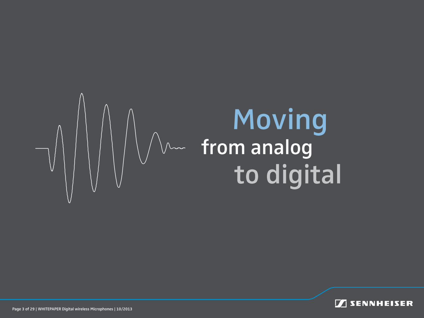
Moving from analog
to digital
Moving from analog to digital
Page 4 of 29 | WHITE PAPER Digital Wireless Microphones | 10/2013
Moving from analog to digital
“With digital wireless transmission, you gave us back the audio quality
we had been missing for so many years when using analog transmitters”
An example of the overwhelming feedback we got when we moved from analog to digital wireless transmission

Page 5 of 29 | WHITE PAPER Digital Wireless Microphones | 10/2013
Signal after analog transmission
Input signal
Signal after digital transmission
Have a look at the diagram on the right and you’ll instantly see how digital wireless trans-mission can improve audio quality.
With analog, you were used to living with transients and overshoots – maybe you even avoided transmitting signals wirelessly when you knew you had sudden dynamic changes like applause or cymbals.
With digital, the shape of the received signal can be exactly the same as that of the one sent out.
Moving from analog to digital

Page 6 of 29 | WHITE PAPER Digital Wireless Microphones | 10/2013
That’s why digital transmission is some-times referred to as cable-like wireless transmission.
It’s not only the audio quality that’s better – digitalization is often considered as the solution to every possible problem of analog systems.
For wireless microphones, one could con-sider that digital transmission will also solve all frequency issues and offer a very long distance range.
The truth is: physics will allow us to improve some of these parameters, but seldom all of them.
So to optimize technology in the right direction, the customer requirements need to be defined clearly.
On the following pages, you’ll see options for how wireless microphone systems for professionals can be designed.
“Interference-free transmission“ is a must – all other requirements are of varying importance.
Moving from analog to digital

Page 7 of 29 | WHITE PAPER Digital Wireless Microphones | 10/2013
Min
Average
Professional customer requirements
In the following diagram, professional customer requirements are visualized.
Certain minimum requirements should be met. Exceeding these minimum requirements is of course always welcome.
Audio quality
Multi-channel capability
MiniaturizationOperating time
Spectral efficiency
Range

Page 8 of 29 | WHITE PAPER Digital Wireless Microphones | 10/2013
Professional customer requirements
It is important to consider that, in a technical solution – shown as blue dots here –, there is a strong relation between the different parameters.
As we are speaking about battery-powered devices, it is very obvious that for example increasing the operating time will limit the miniaturization and so on. This means that the best compromise needs to be found.
Let us have a look at analog and digital transmission solutions.
Audio quality
Multi-channel capability
Miniaturization
Range
Operating time
Spectral efficiency

Page 9 of 29 | WHITE PAPER Digital Wireless Microphones | 10/2013
1) Analog transmission
The diagram shows a typical analog transmission solution.
FM technology is ideal in terms of miniaturization and operating time while audio quality and spectral efficiency are lower than those needed by some professional audio customers.
Let us take the diagram on the right as a reference for the digital solutions shown on the following pages. Please note how the blue dots will change their position.
Audio quality
Multi-channel capability
Miniaturization
Range
Operating time
Spectral efficiency
Analog transmission
Page 10 of 29 | WHITE PAPER Digital Wireless Microphones | 10/2013
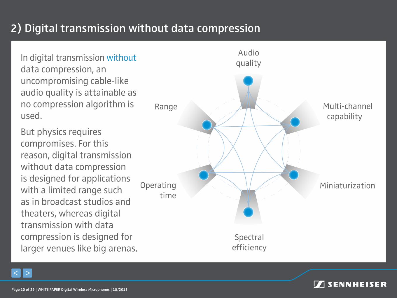
2) Digital transmission without data compression
In digital transmission without data compression, an uncompromising cable-like audio quality is attainable as no compression algorithm is used.
But physics requires compromises. For this reason, digital transmission without data compression is designed for applications with a limited range such as in broadcast studios and theaters, whereas digital transmission with data compression is designed for larger venues like big arenas.
Audio quality
Multi-channel capability
Miniaturization
Range
Operating time
Spectral efficiency
Digital transmission without data compression
Page 11 of 29 | WHITE PAPER Digital Wireless Microphones | 10/2013
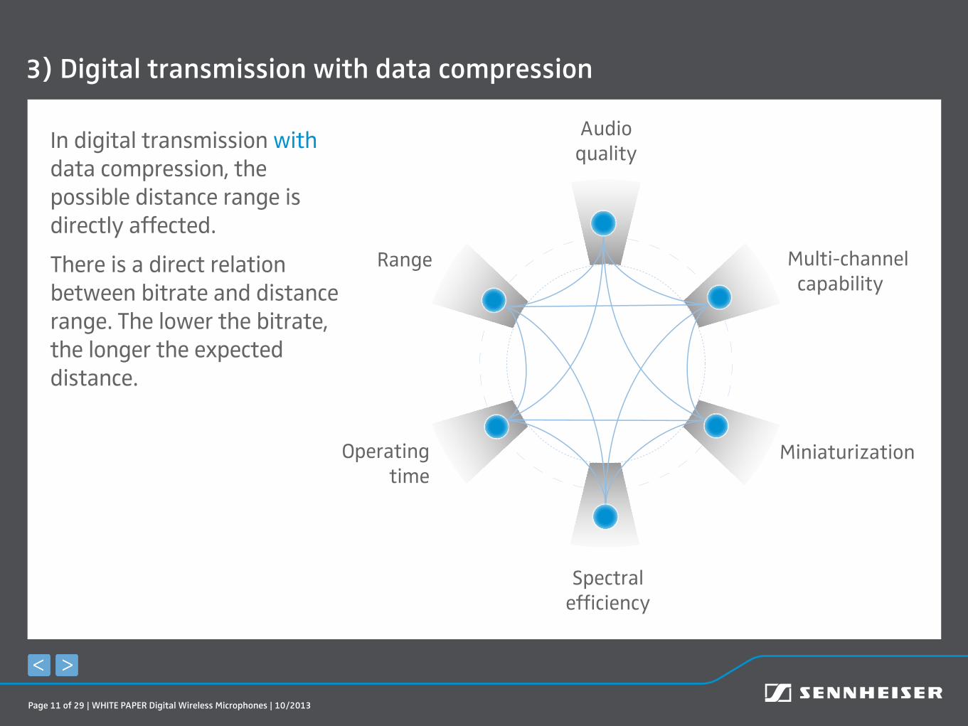
3) Digital transmission with data compression
In digital transmission with data compression, the possible distance range is directly affected.
There is a direct relation between bitrate and distance range. The lower the bitrate, the longer the expected distance.
Audio quality
Multi-channel capability
Miniaturization
Range
Operating time
Spectral efficiency
Digital transmission with data compression

Page 12 of 29 | WHITE PAPER Digital Wireless Microphones | 10/2013
Multi-channel capability
Let us now take a closer look at some of these requirements and interdependencies.
Multi-channel capability
When we speak of professional applications, the number of channels is an important factor.
Today’s demand for multi-channel systems often exceeds 100 channels. At the same time, however, the frequency spectrum is limited.
A good example of this is the Eurovision Song Contest in Malmö.
With its 57-year history, it is the world’s most-watched non-sporting event, broad-casting live to 44 countries in 2013.
For the audio at this year’s event, 96 microphone channels plus 28 wireless monitoring channels were needed.

Page 13 of 29 | WHITE PAPER Digital Wireless Microphones | 10/2013
Multi-channel capability
Approx. 150 frequencies had to be coordi-nated for the microphone and monitoring requirements in Malmö Arena and the ESC press centre.
Multi-channel audio systems with more than 50 channels such as the ones used in Malmö can only be realized in the UHF range.
Other ranges, such as the 2.4 GHz range, cannot carry such a large number of channels.
Operating in the UHF range means that analog and digital systems have to comply with regulations like the European Telecommunications Standards Institute (ETSI) 300-422, which allows a maximum RF channel bandwidth of 200 kHz.
The curve for digital wireless microphones is shown below. All the data needs to be squeezed into this 200 kHz RF channel bandwidth.
-60
-70
-80
-90
-100
-50
-40
-30
-20
-10
0
-1000 -800 -600 -400 -200 0 200 400 600 800 1000 kHz
dB
Digital
Analog
Page 14 of 29 | WHITE PAPER Digital Wireless Microphones | 10/2013
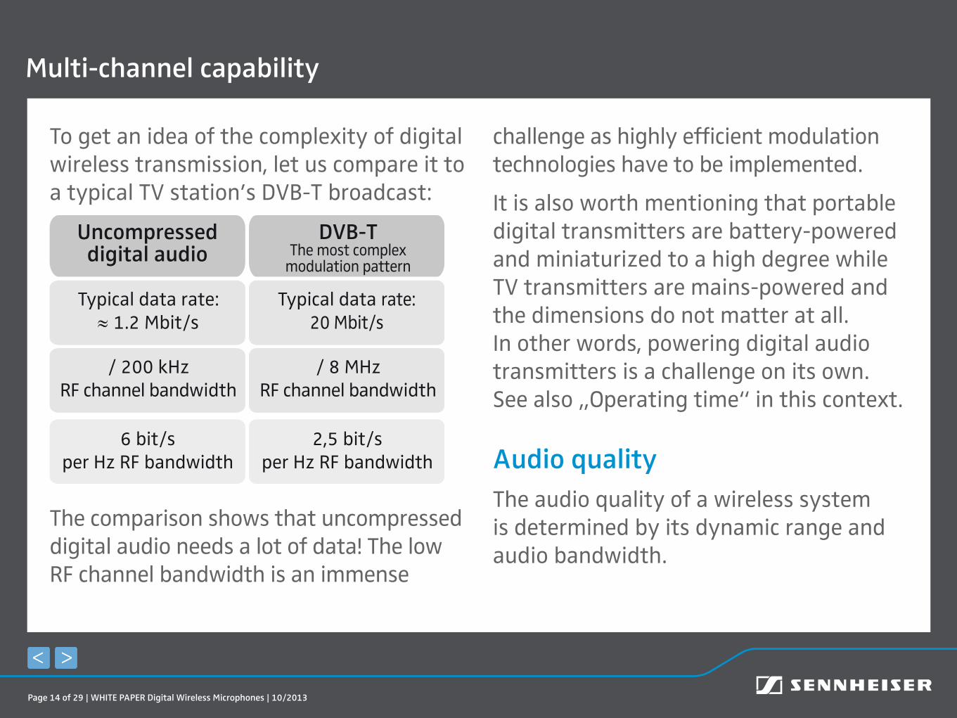
To get an idea of the complexity of digital wireless transmission, let us compare it to a typical TV station’s DVB-T broadcast:
DVB-TThe most complex
modulation pattern
Uncompressed digital audio
Typical data rate:≈ 1.2 Mbit/s
Typical data rate:20 Mbit/s
/ 200 kHzRF channel bandwidth
6 bit/s per Hz RF bandwidth
2,5 bit/s per Hz RF bandwidth
/ 8 MHzRF channel bandwidth
The comparison shows that uncompressed digital audio needs a lot of data! The low RF channel bandwidth is an immense
challenge as highly efficient modulation technologies have to be implemented.
It is also worth mentioning that portable digital transmitters are battery-powered and miniaturized to a high degree while TV transmitters are mains-powered and the dimensions do not matter at all. In other words, powering digital audio transmitters is a challenge on its own. See also „Operating time“ in this context.
Audio qualityThe audio quality of a wireless system is determined by its dynamic range and audio bandwidth.
Multi-channel capability

Page 15 of 29 | WHITE PAPER Digital Wireless Microphones | 10/2013
Dynamic rangeIn a professional wireless audio system, a dynamic range ≥ 110 dB (A) should be achieved, be it analog or digital.
In digital wireless audio systems, each bit of word length delivers a dynamic range of about 6 dB, so to gain ≈ 110 dB (A) of dynamic range, a word length of approx. 18 bits (110/6 ≈ 18) is needed:
Dynamic range
Wordlength
6 dB
6 dB
1 bit
2 bits 12 dB
6 dB18 bits ≈ 110 dB
You may know that high-quality A/D converters have a word length of 24 bits. So why not use the whole word length and gain even more dynamic range?
This is physically impossible. Today’s battery-powered A/D converters suffer
Audio quality – Dynamic range

Page 16 of 29 | WHITE PAPER Digital Wireless Microphones | 10/2013
from self-noise: up to 8 bits of the 24 often contain no audio information at all.It’s the so-called effective number of bits (enob) that counts.
To use the frequency spectrum as efficiently as possible, only approx. 18 bits should be transmitted wirelessly.
Audio bandwidthA professional wireless system’s bandwidth should be approx. 20 kHz.
According to the Nyquist-Shannon sampling theorem, the sample rate has to exceed twice the highest frequency of the audio signal.
With 20 kHz as the highest assumed frequency, a sample rate of approx. 44.1 kHz has to be used.
Let us do a calculation for uncompressed audio signals with 18 bits at 44.1 kHz:
A word length of 18 bits multiplied with a sample rate of 44.1 kHz leads to a data rate of approx. 0.8 Mbit/s:
Audio quality – Audio bandwidth

Page 17 of 29 | WHITE PAPER Digital Wireless Microphones | 10/2013
18 bits · 44.1 kHz ≈ 18·44.1·1000 bit/s = 793,800 bit/s ≈ 0.8 Mbit/s
Additional data due to framing and error correction has to be taken into account, with a factor of 1.5 leading to approx. 1.2 Mbit/s:
0.8 Mbit/s · 1.5 = 1.2 Mbit/s
Regular digital modulations (FSK, PSK or ASK) would only allow for data rates of 150 kbit/s to 300 kbit/s, so very complex high-order modulations are needed here.
In studios, we are often used to digitalizations with 24 bits/96 kHz.
With 96 kHz, the data rate would be around 2.6 Mbit/s – more than twice as much. If we were able to use 24 bits of word length we’d have approx. 3.5 Mbit/s – nearly three times as much. This cannot be transmitted within the requirements of ETSI EN 300 422.
Have a look at the diagram on the following page to get a better impression of the relation between sample rate, bit depth and data rate.
Audio quality

Page 18 of 29 | WHITE PAPER Digital Wireless Microphones | 10/2013
40
20
5k 10k 15k 20k 25k 30k 35k 40k 45k 50k 55k Frequency/Hz
Dynamic/dB
60
80
100
120
140
160
18 bits44.1 kHz
net: 0.8 Mbit/sgross: 1.2 Mbit/s
24 bits96 kHz
net: 2.3 Mbit/sgross: 3.5 Mbit/s
18 bits96 kHz
net: 1.7 Mbit/sgross: 2.6 Mbit/s
Page 19 of 29 | WHITE PAPER Digital Wireless Microphones | 10/2013
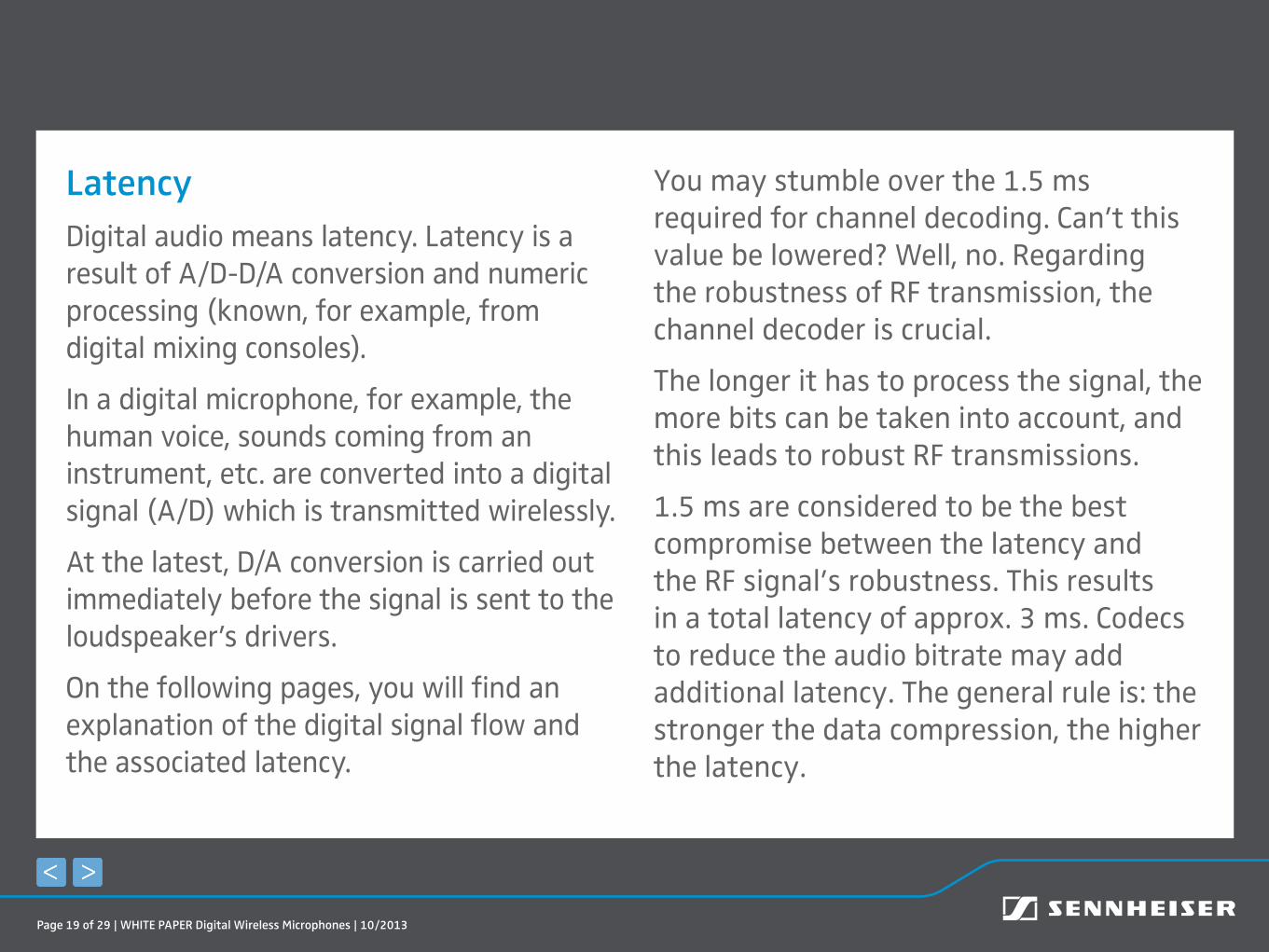
LatencyDigital audio means latency. Latency is a result of A/D-D/A conversion and numeric processing (known, for example, from digital mixing consoles).
In a digital microphone, for example, the human voice, sounds coming from an instrument, etc. are converted into a digital signal (A/D) which is transmitted wirelessly.
At the latest, D/A conversion is carried out immediately before the signal is sent to the loudspeaker’s drivers.
On the following pages, you will find an explanation of the digital signal flow and the associated latency.
You may stumble over the 1.5 ms required for channel decoding. Can’t this value be lowered? Well, no. Regarding the robustness of RF transmission, the channel decoder is crucial.
The longer it has to process the signal, the more bits can be taken into account, and this leads to robust RF transmissions.
1.5 ms are considered to be the best compromise between the latency and the RF signal’s robustness. This results in a total latency of approx. 3 ms. Codecs to reduce the audio bitrate may add additional latency. The general rule is: the stronger the data compression, the higher the latency.

Page 20 of 29 | WHITE PAPER Digital Wireless Microphones | 10/2013
Audio quality – Latency
A/DConv .
AudioCoder
Forward Error
CorrectionBB/RF
0.6 ms X ms 0.2 ms 0.05 ms
.
RF/BBChannelDecoder
AudioDecoder
D/AConv
0.05 ms 1.5 ms Y ms 0.6 ms
.
BB/RF: Baseband/ Radio frequency ICRF/BB: Radio frequency/ Baseband IC
*

Page 21 of 29 | WHITE PAPER Digital Wireless Microphones | 10/2013
Audio quality – Latency
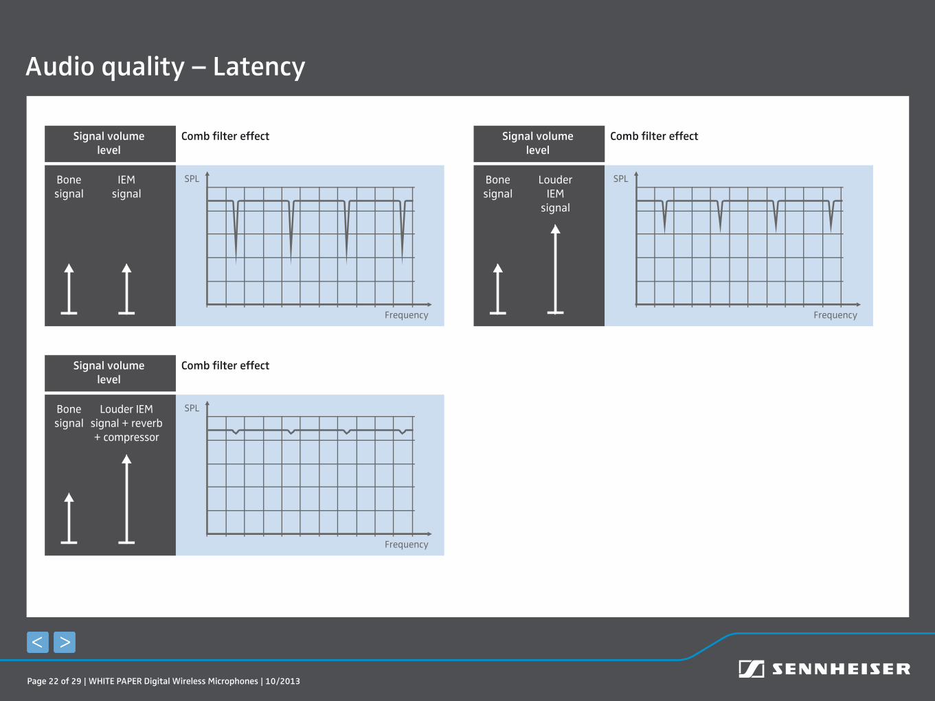
With the introduction of digital mixing consoles in live mixing, the use of IEM systems is considered as the most critical application in terms of latency.
Latency values of a total roundtrip delay of > 4 ms are sometimes considered as inacceptable.
In practice we found that even latency values above 4 ms are hardly audible on stage.
How is that?
A singer hears him- or herself through body vibrations (bone signal) first and then, after a short delay, through the in-ear monitors.
These two signals are similar, but they arrive with different delays. When the sounds are mixed in the ear, the latency leads to sound changes known as the “comb filter effect”. The larger the difference in sound level between IEM and bone signal, the less audible the comb filter effect.
As the isolation of the IEMs earpiece is typically about 20 dB, singers tend to listen to the IEM signal at high volumes, and this drastically reduces the comb filter effect.
Additionally, singers tend to use effects such as reverb and compression on the IEM signals, and these camouflage the comb filtering.
See the diagrams on the following page.
Page 22 of 29 | WHITE PAPER Digital Wireless Microphones | 10/2013
Audio quality – Latency
Comb filter effectSignal volume level
Bone signal
IEMsignal
SPL
Frequency
Comb filter effectSignal volume level
Bone signal
Louder IEMsignal + reverb + compressor
SPL
Frequency
Comb filter effectSignal volume level
Bone signal
LouderIEM
signal
SPL
Frequency
Page 23 of 29 | WHITE PAPER Digital Wireless Microphones | 10/2013
Digital versus analog transmissionDigital wireless transmission behaves differently to analog transmission in terms of audio quality and dropouts.
The audio quality of analog wireless transmission depends on the RF signal quality.
The audio quality of digital wireless transmission is always perfect as long as the RF signal is strong enough compared to the RF noise floor. In addition to this, compressed digital wireless transmission gives the freedom of a long distance range.
See the diagram on the following page for details.
In either case – analog or digital – the clever placement of the
receiving antenna can noticeably improve the signal-to-noise ratio and thereby ensure reliable transmission.
Audio quality – Digital versus analog transmission

Page 24 of 29 | WHITE PAPER Digital Wireless Microphones | 10/2013
Audio quality – Digital versus analog transmission
Digital compressed
Audioquality
Digital uncompressed
RF signal quality
Analog
Squelch Level
(RF mute threshold)
High Low
Low
High
Min. acceptable
audio quality dig vs analog
Page 25 of 29 | WHITE PAPER Digital Wireless Microphones | 10/2013
The frequency spectrum is an important but limited resource. Governments know this, and they sell large amounts to mobile service networks.
For wireless mics, the frequency spectrum is vital. In terms of multichannel systems, only the efficient use of the spectrum will allow operation to continue in the future.
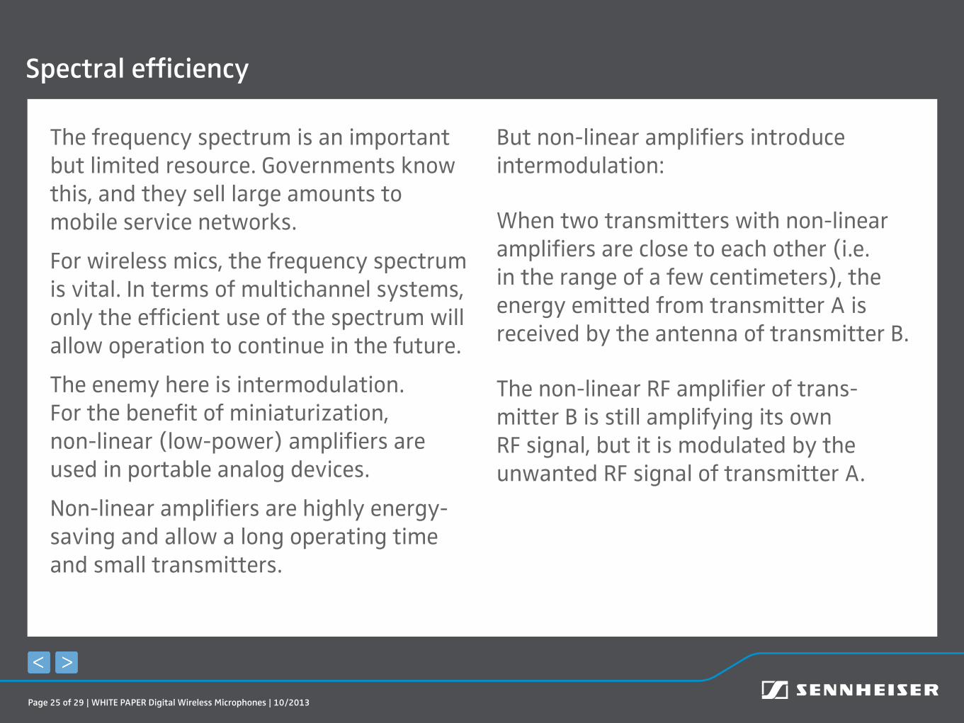
The enemy here is intermodulation. For the benefit of miniaturization, non-linear (low-power) amplifiers are used in portable analog devices.
Non-linear amplifiers are highly energy-saving and allow a long operating time and small transmitters.
But non-linear amplifiers introduce intermodulation:
When two transmitters with non-linear amplifiers are close to each other (i.e. in the range of a few centimeters), the energy emitted from transmitter A is received by the antenna of transmitter B.
The non-linear RF amplifier of trans-mitter B is still amplifying its own RF signal, but it is modulated by the unwanted RF signal of transmitter A.
Spectral efficiency
Page 26 of 29 | WHITE PAPER Digital Wireless Microphones | 10/2013
Spectral efficiency
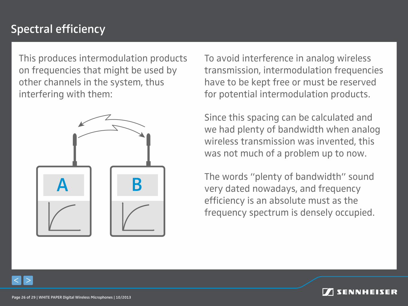
This produces intermodulation products on frequencies that might be used by other channels in the system, thus interfering with them:
A B
To avoid interference in analog wireless transmission, intermodulation frequencies have to be kept free or must be reserved for potential intermodulation products.
Since this spacing can be calculated and we had plenty of bandwidth when analog wireless transmission was invented, this was not much of a problem up to now.
The words “plenty of bandwidth” sound very dated nowadays, and frequency efficiency is an absolute must as the frequency spectrum is densely occupied.
Page 27 of 29 | WHITE PAPER Digital Wireless Microphones | 10/2013
Moreover, while analog systems using Frequency Modulation (FM) have no problems demodulating signals generated by non-linear amplifiers, there is a need for linear amplifiers in digital systems.
So when developing digital transmitters, wireless transmission has to be rethought from the ground up.
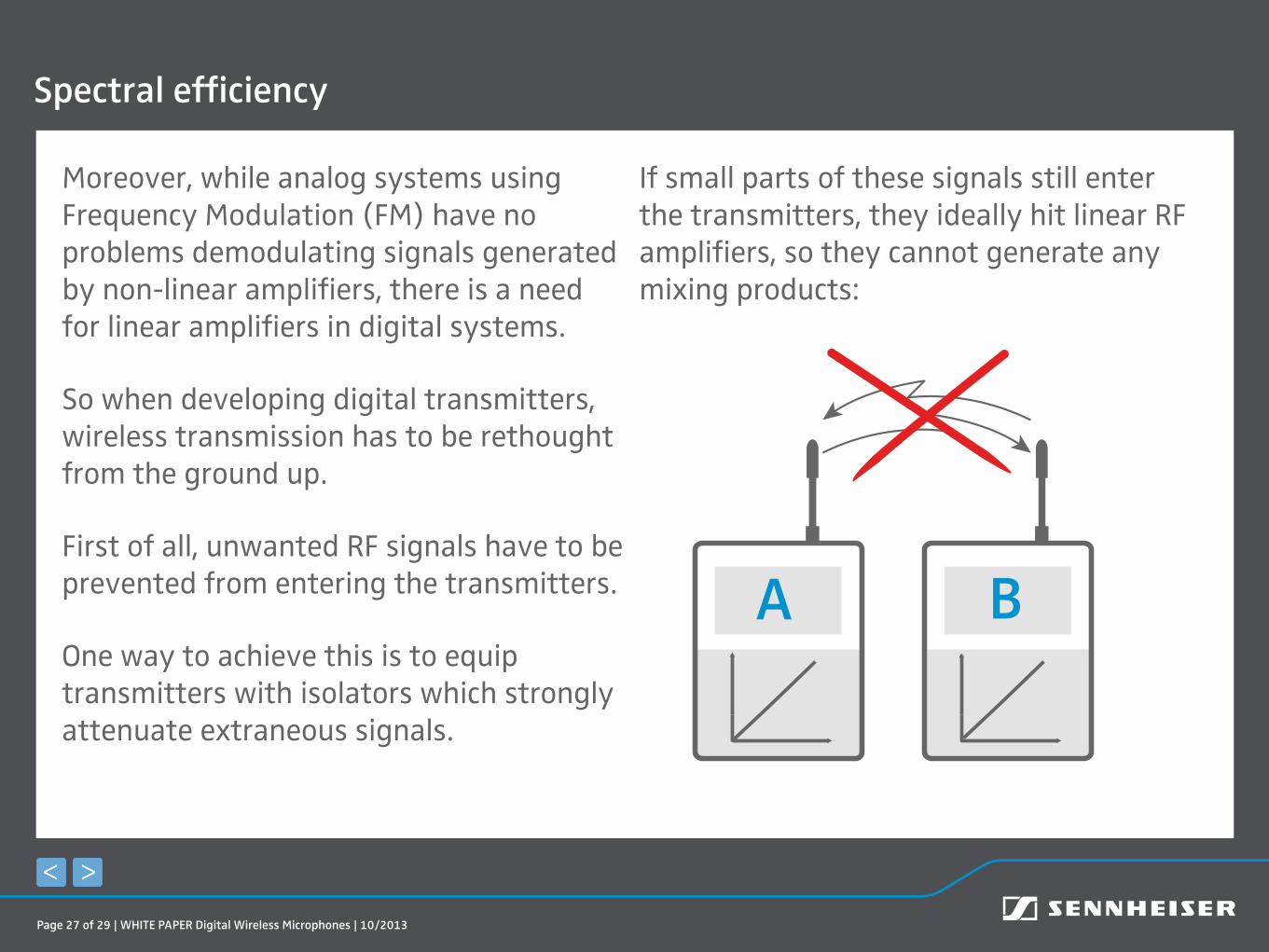
First of all, unwanted RF signals have to be prevented from entering the transmitters.
One way to achieve this is to equip transmitters with isolators which strongly attenuate extraneous signals.
If small parts of these signals still enter the transmitters, they ideally hit linear RF amplifiers, so they cannot generate any mixing products:
A B
Spectral efficiency

Page 28 of 29 | WHITE PAPER Digital Wireless Microphones | 10/2013
This design will reduce transmitter intermodulation so that the transmitters can be very close (< 10 cm) without producing harmful intermodulation.
If the receivers and boosters/antennas in a digital system also have highly linear amplifiers, intermodulation won’t interfere at all on the receiver side.
This could also be realized with analog transmitters, but as more
linearity is achieved at the expense of energy efficiency, it has hardly ever been done.
Such digital systems are highly efficient spectrally. Transmitter intermodulation can be drastically reduced, so that the frequencies can be used in an equidistant channel grid (see the diagram on the following page).
This would not have been possible in a conventional (analog) transmission system.
Spectral efficiency

Page 29 of 29 | WHITE PAPER Digital Wireless Microphones | 10/2013
Frequency setup in conventional systems
Frequency setup in a highly linear digital system
Operating timeLinearity is achieved at the expense of en-ergy efficiency. So when portable digital transmitters are used, energy has to be used as efficiently as possible and energy packs need to have a high energy density.
All components must be energy-saving and Li-Ion technology should be used.
Operating time & distance range