when welding components to the frame assembly, remove … required, following procedures as outlined...
TRANSCRIPT
PA
GE
1S/T TRUCK
S/T Rev. 12/98
BODY BUILDERS INSTRUCTIONS
The Incomplete Vehicle Document (IVD) is supplied with each incomplete vehicle,and provides information that should be used by intermediate and final stagemanufacturers in determining conformity to applicable Federal Motor Vehicle SafetyStandards (FMVSS). The IVD also includes information which must be followed inorder to ensure that Environmental Protection Agency (EPA) and California emissionscertification requirements and NHTSA Fuel Regulations are met.
The Body Builders Manual contains information that may be used in addition to theIVD for any manufacturer making alterations to an complete/incomplete vehicle. Noalteration should be made to the incomplete vehicle which either directly or indirectlyresults in any component, assembly or system being in nonconformance with any ap-plicable Federal Motor Vehicle Safety Standard or Emission Regulation. Intermedi-ate and final stage manufacturers should be familiar with all Federal Motor VehicleSafety Standards and Emission Regulations and aware of their specific responsibili-ties as manufacturers.
For further assistance contact Upfitter Integration at: 1 (800) 875-4742
Section 0 – General Instructions
Check for proper clearance between body members and chassis components whichmay in any way affect the reliability and performance of the vehicle by developingabrasion and wear points from moving parts or degradation from extreme environ-ment or thermal exposure or may increase interior noise.
Check headlamp aim and all vehicle illumination systems for proper operation whenthe vehicle has been completed. Re-aim headlamps when necessary. Check forproper operation of windshield washer, wipers and defroster system.
Extreme care must be taken when working on vehicles equipped with Powertrain Con-trol Module (PCM), Vehicle Control Module (VCM) or any electronic unit associatedwith an inflatable restraint system. (See Owner’s Manual).
If arc-welding is employed on the chassis, precautions must be taken to protect allvehicle components, especially brake, fuel lines and fuel tank assembly, electrical wir-ing and ECM/PCM/TCM or VCM. To avoid electronic component damage, disconnectbattery (batteries); disconnect the negative cable first, followed by the positive. Toreconnect cables; connect the positive first, then the negative.
When welding components to the frame assembly, remove the wax coating in the areaof the weld in order to obtain secure welds. After completion of the weld, a compatiblecorrosion protection should be applied to the affected weld areas.
All labels on the vehicle (any message applied to the vehicle or vehicle componentthat informs, instructs, or warns) must appear on the completed vehicle so the usercan read them easily and without obstruction.
Service and service replacement parts for your add-on systems may not be availablefrom a GM dealer. Those installing aftermarket systems should provide informationas to where and how to obtain service.
Section 1 – Body
Body structures, interior and accessory arrangements must be designed into the ve-hicle to provide for proper load distribution on both axles and not to exceed any grossaxle weight ratings. Lateral load equalization must also be maintained. The resultantCenter of Gravity of the unladen vehicle must be within the limits tabulated in theFMVSS 105 section of the Incomplete Vehicle Document.
Body insulation provided by General Motors should not be removed. This includesany thermal or underbody heat shields. This insulation is provided to protect the ve-hicle body and occupants from excessive heat and/or provide noise attenuation. Anyreplacement material internal to the occupant compartment must be certified forMVSS standard on flammability. Areas of specific concern, but not limited to are:
� Underbody exhaust, muffler and tailpipe shields and insulators.
� Rear load floor interior insulation.
� Front floor interior insulation.
� Dash mat insulation.
� Engine cowl insulation – interior and exterior.
� Engine cover insulation.
If body builder installs seating other than that supplied with vehicle, it is the body build-er’s responsibility to ensure that the seating and restraint systems comply withFMVSS requirements. The restraint systems supplied with the vehicle were designedto accommodate the seating reference points and seat travel of the original equip-ment seats only.

PA
GE2 S/T TRUCK
S/T Rev. 12/98
Air Conditioning
For additional information refer to Engine – Section 6 .
NOTE: Air conditioning systems using R-134A refrigerant are equipped with metric fittingsto prevent interchange with R-12 refrigerant components. Do not interchangeR-134A components, refrigerant oil or service equipment with R-12 components,refrigerant oil or service equipment.
Section 2 – Frame
Hole drilling, welding, modifications, or alterations to the frame assembly are the re-sponsibility of persons performing these operations. These same individuals assumecomplete responsibility for frame assembly reliability, performance after alterationsand compliance to applicable FMVSS requirements.
The following procedures and specific precautionary instructions are recommendedfor proper installation of special bodies and/or equipment on GM frames. Failure tofollow these recommendations could result in serious damage to the basic vehicle.
Flanges
Do not drill holes in frame flanges.
Holes
Holes to mount brackets, supports, and out-riggers must be drilled in the vertical siderail web with the following restrictions:
� Material between edge of hole and inside of upper or lower flange must not beless than 37 mm (1.50 in.) for low carbon steel (36,000 PSI yield).
� The minimum edge distance between any two (2) holes must be larger thantwice the diameter of the larger hole.
� No holes should exceed 20 mm (0.75 in.) in diameter.
� All holes should be drilled in the frame using appropriate drilling practice andsafety precautions.
Welding
CAUTION: Fuel tank and fuel lines must be drained and all vapors purged to ensurenon-combustible mixture before any welding, brazing or soldering.
When welding low carbon steel side rails, crossmembers and brackets (32,000 or36,000 PSI yield strength), emphasis is placed upon weld application techniques toavoid stress risers that may adversely affect frame operating stresses.
When welding is performed anywhere on the vehicle, precautionary measures shouldbe taken to prevent damage to electrical system wiring or components. Prior to anywelding, parts or components which could be damaged by excessive temperaturesmust be removed or adequately shielded; the battery cables should be disconnectedat the battery. Also prior to welding, the area to be welded and surrounding area mustbe cleaned of all frame protective coating. After welding, when parts are cool, careful-ly inspect wiring and electrical components for shorts or other damage which coulddraw excessive currents and possibly cause an electrical system short when the bat-tery is reconnected. Apply protective coating to areas where coating was removed.
Alterations
If the wheelbase is modified the alterer must take responsibility for compliance withaffected motor vehicle safety standards and for warranty on items such as drive-shafts, universal joints, center bearings and rear transmission tailshaft, transfer caseand transmission case fractures, output shaft bushings, bearings, brakes, fuel sys-tems and any other related component failures. Additionally, the customer must bealerted in the modifier’s owners manual that parts for the reworked area are not avail-able through the General Motors service parts system.
Shear Plate Attachments
Attachments of shear plates should be accomplished by using existing manufacturingholes already available in the frame side rails. Manufacturing holes, normally 16 mmin diameter, are consistently placed along the frame side member in the center of theweb on each frame.
When additional holes are required for shear plate attachment, they should be no larg-er than 20 mm (0.75 in.) in diameter. Holes are to be drilled no closer than 63.5 mm(2.5 in.) apart. For holes drilled forward of the rear axle, centers are to be no closerthan 63.5 mm (2.5 in.) from the top or bottom flanges and no closer than 89 mm (3.5in.) from any suspension attachments. For frame holes drilled rearward of the rearaxle, hole centers are to be no closer than 51 mm (2.0 in.) from the top or bottom flangeand no closer than 89 mm (3.5 in.) from suspension attachments.
No additional holes or notching of either top or bottom frame flanges is allowed.

PA
GE
3S/T TRUCK
S/T Rev. 12/98
Rear bodies or platforms added to the vehicle must utilize the released attachmentpoints used by the pick-up box, along with fasteners of the same diameter. Theseare minimum requirements; additional fasteners are permissible.
Section 3 – Front Suspension
See chassis data information for clearances and assistance in calculating trimheights.
Since there is a large variation in completed vehicle front weight due to differencesin body weight and equipment, the front suspension alignment must be checked andreset if necessary after the vehicle is completed. Caster and camber should be setwith reference to the “A” dimensions.
See Truck Service Manual for complete alignment procedure, specifications andmeasurement of the “A” dimension under “Diagnosis and Front Alignment” section.
Section 4 – Rear Suspension
Clearance to body should be provided for the suspension, axle, driveshaft and tiresunder the following conditions: (1) Axle in full jounce against the metal-to-metal stop,(2) Axle at 4.5° roll with one side of axle in full jounce at the metal to metal stop and(3) Axle at design position. Allowance for the tire chain clearance shown on a maxi-mum grown tire must allow for (1.66 in.) clearance to the sides of the tire and (2.5 in.)to the top of the tire. Be sure sufficient clearance is provided for suspension, axle andtire and wheel in full vertical travel (up and down).
NOTE: Notification to the consumer may be required in certain states if tire chains cannotbe used.
Pipes, wiring, conduits and any other related components must not be placed wherethey cross the path of motion of the rear axle, driveshaft, axle brake pipes, hoses,spring or tires. Such crossing could result in rupture, wear-through, or separation dueto normal axle motion.
See chassis data information for additional clearances and for assistance in calculat-ing trim heights.
Section 5 – Brakes
See Truck Service Manual for brake specifications.
Due to the critical nature of brake systems, anyone making modifications or alter-ations must assume complete responsibility for system reliability, performance andcertification to FMVSS 105 or FMVSS 121.
It is mandatory that no change be made to the brake main cylinder location, brake ped-al push rod length or pedal position.
Ensure that hydraulic brake system is free of air and hydraulic leaks. Bleed brakesif required, following procedures as outlined in truck chassis service manual. Ensurethat vacuum booster system or hydroboost system is functional and free of leaks.
Check master cylinder fluid level and fill as necessary. (Refer to Owner’s Manual).
Check power steering fluid level for models equipped with hydroboost brake. (Referto Owner’s Manual)
Added floor covering or carpeting must not restrict service or parking brake pedal trav-el from released position to full pedal travel.
No body part or chassis-mounted component may be located within 2.0 in. of brakehose routing in all wheel and axle positions. All exhaust system components must alsohave a minimum of 2.0 in. clearance to brake hoses in closest positions. (Be sureto account for brake hose travel with suspension).
Body builder is to verify that the brake warning switch is operative. The brake warningswitch on models equipped with vacuum-hydraulic brakes is located adjacent to themaster cylinder vacuum unit. This includes both the brake system differential pres-sure and parking brake actuator switch.
Section 6 – Engine
For additional information refer to Body - Section 1 .
Air conditioning and auxiliary belt-driven equipment installation recommendations:
No alterations or additions to the accessory drive belt system will be warranted on ser-pentine belt systems.
The serpentine belt type of drive is designed as a total system, incorporating a singlepoly-V belt and an automatic tensioner. In this type of system, degrees of pulley wrap,belt tension, and pulley alignment are very critical factors. Modification is not recom-mended.
In some single belt serpentine systems, belt tension is determined by the automatictensioner and its position relative to the belt. No adjustment is required.

PA
GE4 S/T TRUCK
S/T Rev. 12/98
Due to the critical nature of the accelerator system, anyone making modifications oralterations assumes complete responsibility for system reliability, performance andcompliance to FMVSS 124. Caution must be exercised so that the accelerator cableis properly routed. Specifications are as follows:
� Route cable to maximize all bend radii. In no case should bend radii be lessthan 3 in. (76 mm).
� Minimum distance from exhaust manifold to be 6.0 in. (150 mm), unless a heatshield is provided.
� Do not use accelerator cable or clips to route wires, harnesses or other cables.Cable sheath must be clipped so as not to pinch inner cable. Cable must notbe loose in clip allowing sheath to move when accelerator pedal is applied andreleased.
� Cable must not be subjected to kinking or routing across any sharp edges.
� Cable routing must be perpendicular to the surface of the front-of-dash at thedash fitting. No objects or routings should force cable to have a bend at thedash fitting. Flexible components (hoses, wires, conduits, etc. ) must not berouted within 2.0 in. (50 mm) of moving parts or accelerator linkage unlessrouting is positively controlled.
� Caution must be taken so that the accelerator pedal remains properly located.Guidelines for accelerator pedal locations are as follows:
— Ensure that the accelerator can freely operate from idle to wide-open throttleposition and return. Make sure that the pedal will not hang up on any nearbyitems such as carpets, floor, screws, wiring harnesses, etc. Engine covershould have at least one inch (25 mm) clearance to side of accelerator pedalwith the carpet mat installed.
— Accelerator to brake pedal relationship has been designed to provide mini-mum driver movement and should not be altered in any way.
Gasoline engine induction and/or ignition system is certified in compliance with theFederal Vehicle Emission Standards. Any alterations to the systems or componentscould void compliance and render the vehicle illegal. System includes:
� Fuel system – throttle body and port fuel injection (PFI) or sequential centralport injector (SCPI) and associated tubes, hoses and pipes, air cleaner outsideair hose, mass air flow sensor, fuel pump and inlet manifold, fuel vapor canister.
� Exhaust system.
� Ignition system distributor and initial spark timing setting, spark plugs, sparkplug wires.
� Crankcase ventilation system.
Section 7 – Transmission
Light duty models equipped with manual transmission have a clutch-operated startsafety switch. Starter should operate whenever the ignition is turned to start and theclutch is fully depressed. Readjust if necessary as outlined in the Truck Service Manu-al.
Models equipped with automatic transmissions have a steering column mounted ora transmission mounted neutral/park start safety mechanical lockout feature, whichinterfaces with the steering column ignition switch. Starter should operate only whengear shift lever is in neutral or park position. Readjust the shift linkage or neutral startbackup switch if necessary as outlined in the Truck Service Manual.
Models equipped with manual transmission use a hydraulic clutch actuator. Checkfluid level as outlined in the vehicle owners manual.
It is mandatory that no change be made to the clutch master cylinder location, clutchmaster or slave cylinder push rod length, or pedal postion.
Section 8 – Fuel and Exhaust
Fuel Systems
Due to the critical nature of sealing the fuel system, anyone making modifications oralterations to the existing system must assume complete responsibility for the systemreliability, performance and compliance to FMVSS 301.
The fuel evaporative emission control equipment is certified to be in compliance withthe Federal and California Vehicle Emission Standards. Any alterations to systemsor components and their location could void compliance. System includes:
� Fuel tank, metering unit, lines including purge control solenoids and canisteror canisters.
For these reasons,
NO ALTERATION OF THE FUEL SYSTEM IS RECOMMENDED
Fuel Lines
Fuel line routing precautions:
� 12 in. minimum clearance to exhaust system is required or a metal shield mustbe provided.

PA
GE
5S/T TRUCK
S/T Rev. 12/98
� Fuel lines should be clipped to chassis to prevent chafing. Metal clips musthave rubber or plastic liners.
� Use corrosion resistant steel tubing with short sections of approved hose toconnect components. Hose-to-tube connections should be clamped for dieselsystems. Steel tube ends should be beaded for hose retention. Fuel supplyis pressurized by an in-tank pump for PFI and SCPI systems. Coupled hoseor nylon quick-connects must be used. Clamped hose is not acceptable for PFIand SCPI systems.
All engines require a fuel return system which returns excess fuel from the injectionpump and injector nozzles back to fuel tanks. Care should be taken that these linesare not blocked nor their hoses pinched. The engine may run poorly or stall if theselines are restricted or blocked.
All gasoline engine vehicles are equipped with fuel evaporative emission controlequipment which is certified to be in compliance with the Federal or applicable Califor-nia vehicle emission standards. Alterations to fuel tank and metering unit, lines, can-ister or canisters, canister filters, canister purge control valves, relay switches, tankauxiliary vent valve, engine speed controller, or other devices/systems are thereforenot allowable since vehicle adherence to C.A.R.B. and Federal regulations may beaffected.
Diesel powered vehicles incorporate water drain provisions in the fuel system. Thesevalves are only to be opened when siphoning water and contaminants from the fuelsystem.
Fuel Tank
For vehicles with full frames, the tank must have a minimum clearance of 2 in. top,front, rear and sides to body and other supports.
Tank may be pressurized to 1.25 PSI maximum to check for final line leakage or forforcing fuel through the system. Pressures greater than this amount may be detrimen-tal and affect tank durability.
The use of auxiliar y fuel tanks is not recommended. If an auxiliary fuel tank is add-ed, the alterer must take responsibility for compliance with affected motor vehiclesafety standards. Also, if an auxiliary fuel tank is added to a gasoline-powered ve-hicle, the fuel must be drawn through a pipe at the top of the tank (balance line be-tween tanks is not permitted).
Gasoline fueled vehicles are now equipped with a fuel pump return line. If an auxiliarytank is added, the tank selector valve must include a return port which returns fuelto the tank from which the fuel is being drawn.
In gasoline engines the fuel pump is located in the fuel tank. The battery must be dis-connected before starting any work on the fuel system.
In the use of dual fuel systems, the vehicle operator should strictly adhere to themanufacturer’s procedures for switching from gasoline to gaseous fuel operation.Improper switching procedures may result in overheating and damage to the exhaustsystem and the vehicle. The gaseous fuel tank should not be mounted in an enclosedarea of the vehicle, such as the passenger compartment, truck, etc., and the systemshould be vented to the outside of the vehicle. In addition, vehicles converted to gas-eous fuels should not be stored in enclosed places such as garages. Further, GeneralMotors cautions purchasers that the design, location and installation of any type offuel storage system involves significant technical and engineering considerationsand that these statements on gaseous fuel conversions should not be interpreted tobe an approval by General Motors of any modification to the original equipment fuelsystem.
Conversions to gaseous fuel should be made in conformance with applicable Federaland State regulations. Removal of emission-control components, or the addition ofgaseous fuel systems which could damage or reduce the longevity of those compo-nents and could also cause the mechanical and emission performance warranty tobe voided.
Exhaust System
Particular care should be taken to prevent the possibility of exhaust fumes and carbonmonoxide exposure to vehicle occupants in units completed by body builders. Holesand openings through the floor and all other parts of the body must be permanentlyand adequately sealed by the body builder to avoid exhaust intrusion into any occu-pant area. If it is necessary to change the exhaust outlet location, the exhaust dis-charge must be unobstructed and directed away from occupant areas. Alteration ofthe exhaust outlet or its position may increase exhaust noise and render the vehicleillegal in those areas with pass-by noise regulations. All vehicles >10,000 lbs. GVWRcome under Federal noise regulation of the Environmental Protection Agency; ve-hicles < 10,000 lbs. GVWR are regulated by various state and local regulations of thesee those regulations for rules, test procedure and noise levels permitted.
Tail pipe outlet location must be tested statically and with the vehicle in motion to en-sure that exhaust gases do not penetrate side or rear windows or under body seamsand holes. Auxiliary power plants should also be tested under the same conditions.Tail pipe exit ahead of rear wheels is not recommended.
Check for leaks in exhaust systems and repair as required.
Any exhaust joint which has been disassembled must have the exhaust gasket re-placed and the fasteners torqued to specifications. Re-check exhaust system forleaks.
Exhaust temperatures can exceed 1600�F under extreme operating conditions, withpipe surface temperatures slightly less than this. Extreme care must be used whenplacing body components in the proximity of the exhaust system so as not to exceed

PA
GE6 S/T TRUCK
S/T Rev. 12/98
the rated temperature limits of the components. Due to variants in underbody configu-rations of the vehicles, we are not in a position to make recommendations on how toinsulate or design components in the proximity of the exhaust system.
Each manufacturer must make temperature checks of critical areas of his vehicle andadjust his design accordingly, or provide shielding to ensure safe operation of his bodycomponents.
The same can be said for the engine compartment. Obviously there will be additionalheat radiated from the engine. How much is retained in the area will depend on howwell this area is ventilated in your individual designs. Here again, temperature checksof interior areas surrounding the engine should be made to determine if your insula-tion is adequate. This is the same engineering practice we have followed on our com-plete vehicles incorporating these exhaust systems.
Exhaust system materials are selected and tested to withstand the operating environ-ment of the vehicle. Do not modif y the exhaus t syste m in any way. The tail pipesare made of 409 aluminized stainless steel.
Heat shields are mounted to the underbody and/or exhaust system components (cat-alytic converter, muffler and tailpipe). Shields for the propshaft hanger bearings arealso provided in some vehicles.
Section 9 – Steering
Check power steering fluid level and system operations. (Refer to Owner’s Manual).
Steering wheel and horn pad must not be altered or replaced.
The steering column mast jacket not to be altered.
Section 10 – Tires
Check wheel lug nuts for proper torque; specifications are provided in the Owner’sManual.
Substitution of tires of greater capacity than those offered as original equipment byvehicle manufacturer is not approved for use on original equipment wheels. Anyusage of higher capacity tires must be accompanied by higher capacity wheels. How-ever, the wheel offset and distance from centerline of rim to wheel mounting face mustbe the same as the replaced original equipment wheel to ensure proper wheel bearingloading and clearance of tires to body and chassis components.
Increasing tire and wheel capacity does not necessarily increase vehicle GVW rat-ings.
It is recommended that tire chain clearance guideline, J683 from the Society of Auto-motive Engineers be adhered to in designing rear wheelhouse clearance.
Check tires and inflate to recommended tire pressure according to the tire pressureinformation provided in Owner’s Manual and tire inflation label provided with vehicle.
Any substitution of tires may affect Speedometer/Odometer accuracy.
Section 12 – Electrical Battery and Battery Cables
The vehicle battery should be located and positioned to make use of the existing bat-tery cables. If the battery requires relocation and longer cables are required, a propor-tionately larger gauge wire must be used. If in relocating the battery the negativeground cable is attached to frame rail, a cable of similar gauge be provided betweenthe frame rail and the engine. This is required due to the heavy electrical loads im-posed by the starting circuit. To ensure proper operation of the battery cables the fol-lowing chart on length, gauge and materials must be strictly adhered to:
Combined length of positive and negative
Cable Gauge Cable in Inches (Copper)
� ��
� ���
� ���
If the battery is remotely mounted (other than in the engine compartment) the ‘sense’circuit in the generator regulator shall be used. The sense circuit consists of a 7.76OHM 1/4 watt resistor connected in series between the ‘S’ terminal of the generatorand the B+ terminal of the battery.
Modifications/add-on wiring must be carefully reviewed to ensure compatibility withthe base vehicle wiring by reviewing system schematics, wire routing paths, harnessconnections, etc. Due to the wide range of modifications that may be required forvocational needs, it is not feasible for the O.E.M. to take into account all potential revi-sions. For this reason, any person modifying existing vehicle wiring must assume re-sponsibility that the revisions have not degraded the electrical system performance.Any add-on wiring must be properly fused and routed to prevent cut, pinch, and chafeproblems, as well as avoid exposure to excessive heat. Care must be exercised thatexisting vehicle interfaces do not have their current load capabilities exceeded, andthat the respective control devices are not overloaded. Added wire size should be at

PA
GE
7S/T TRUCK
S/T Rev. 12/98
least as large as the the wire to which it is attaching in order for fuse protection to bemaintained.
A Packard electric wiring repair kit is available through Kent–Moore (GM P/N12085264, Kent–Moore P/N J38125-4). This kit contains instructions, tools and com-ponents for making repairs to wiring harness components. This kit would also greatlyassist in accomplishing necessary add-on wiring such as body marker lamps, so thatsystem reliability/durability is maintained.
Electrical wiring components can be obtained through your authorized GM dealer.Many Packard Electric components are also available through Pioneer StandardCompany (1 800-PACKARD). Pioneer may also be able to assist in making necessarywiring additions by providing custom wiring stubs or jumpers to your specifications.
Fusible Link Repair Procedure:
1. Cut damaged fusible link from wiring harness assembly splice.
2. Strip insulation from harness wire as required to splice on new fusible link.
3. Fabricate a new fusible link wire approximately 6 to 8 in. long from the same wiresize as the original link. (Acceptable fusible link material will be imprinted with thewire size and the wording to identify it as fusible link. Fusible link cable is not thesame as normal vehicle wiring.)
4. Terminate fusible link harness wire with a suitable compression splice clip, and sol-der with an electrical grade rosin core solder. Wrap splice area with tape to provideelectrical insulation, as well as mechanical strain relief at the splice.
5. Strip, terminate, solder, and insulate remaining end of fusible link with appropriatetermination to be compatible with the rest of the electrical system.
6. For further information, refer to the instruction manual in the wiring repair kit refer-enced elsewhere in this section.
Accessory Power Supply Feed:
For power requirements to service additional devices to be added by body builder/up-fitter, the power supply source must be at the junction block on the front of dash abovebattery using the small on the left-hand side of junction block.
NOTE: A ground stud has also been provided above the junction block.
Section 13 – Cooling
To provide satisfactory engine cooling, the following conditions must be met:
1. Do not locate any large objects in front of the radiator core or grille such as batteries,spare tires, lights/sirens, etc. They restrict air flow into the radiator core and influ-ence fan blade stress .
2. Grille opening, size configuration and the external baffles provided should not be al-tered in any manner. Any reduction in cooling ability may adversely affect engine/transmission performance.
3. Fan clutches not conforming to the original equipment specifications may not oper-ate correctly and may stay “on” continuously, never come on, or cycle on and off ex-cessively. This will result in a reduction of fuel economy, engine overheat at times,and annoying cycling respectively.
4. Continuous coolant flow is necessary from heater connection on engine-to-heaterconnection on radiator to control transmission oil temperatures during closed ther-mostat (warm-up) operation. Do not alter this flow as it may result in premature en-gine or transmission failure.
5. If a heater unit is not installed in the vehicle or a heater shut-off valve is required,a line connecting the heater connection on the engine to the heater connection onthe radiator must be installed. When a shut-off valve is required in heating system,it must be teed into the system in such a manner as to maintain continuous flow be-tween engine heater connection-radiator heater connection at all times.
6. Use GM 6277M Long Life Coolant only.
Do not install any internal flow restrictors.
� Heater hose:3-way or 4-way valves must be used to provide constant water flow through theintake manifold pad area.
� If in-line shut-off valve is used in combination with 3 way valves, shut-off valvemust not be closed until 3-way valve at engine is in the proper position.
Valve Sources:
� ���Red-White Valve Corp., Carson CA ����� � �����
�����Ranco Controls Div., Delaware, OH ���� �������
����� Ranco Controls Div., Delaware, OH ���� �������
Be sure to add coolant to system after adding capacity to system (heaters).

PA
GE8 S/T TRUCK
S/T Rev. 12/98
S/T 10003 Pickup, General Arrangement

PA
GE
9S/T TRUCK
S/T Rev. 12/98
S/T 10516–2 Door Utility, General Arrangement

PA
GE10 S/T TRUCK
S/T Rev. 12/98
S/T 10506–4 Door Utility, General Arrangement

PA
GE
11S/T TRUCK
S/T Rev. 12/98
PICKUP WEIGHT DISTRIBUTION
� See Note� See Note123.0170.1
85.570.8
Pickup BoxShort Long108.0 118.0155.5 171.4
Regular Cab Extended Cab
Model Wheelbase (in )Body-Cargo Weight Distribution
Model Wheelbase (in. )% Front % Rear
108.0 1 99
S 10003 118.0 1 99S 10003123.0 3 97
108.0 1 99
T 10003 118.0 1 99T 10003
123.0 3 97
* Note: Reference Front End Sheet Metal Arrangements
S/T PICKUP BOX REMOVAL PROGRAM
IMPORTANT: There is not a 1999 GM approved pickup box removal program for the S 10803 Chevy or GMC pickup.

PA
GE12 S/T TRUCK
S/T Rev. 12/98
S/T 10603 Pickup, Regular Cab with Short Box, General Arrangement

PA
GE
13S/T TRUCK
S/T Rev. December, 1998
S/T 10603 Pickup, Regular Cab with Short Box, Hi-Wider, General Arrangement

PA
GE14 S/T TRUCK
S/T Rev. 12/98
S/T 10603 Pickup, Regular Cab with Short Box, Isuzu, General Arrangement

PA
GE
15S/T TRUCK
S/T Rev. December, 1998
S/T 10803 Pickup, Regular Cab with Long Box, General Arrangement
PA
GE16 S/T TRUCK
S/T Rev. 12/98
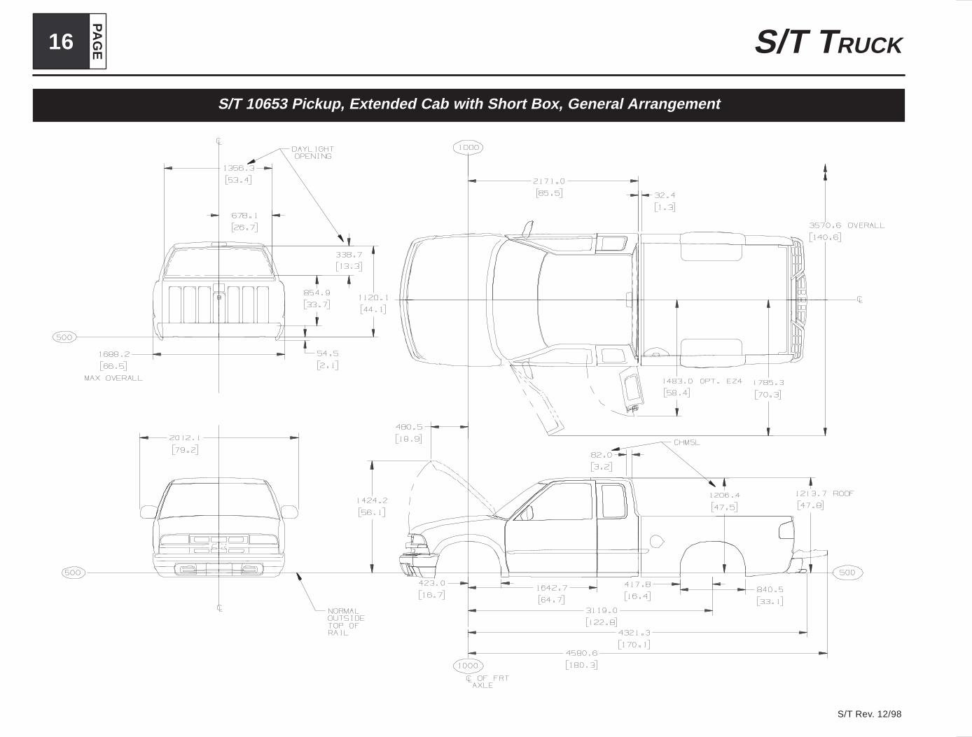
S/T 10653 Pickup, Extended Cab with Short Box, General Arrangement
PA
GE
17S/T TRUCK
S/T Rev. December, 1998
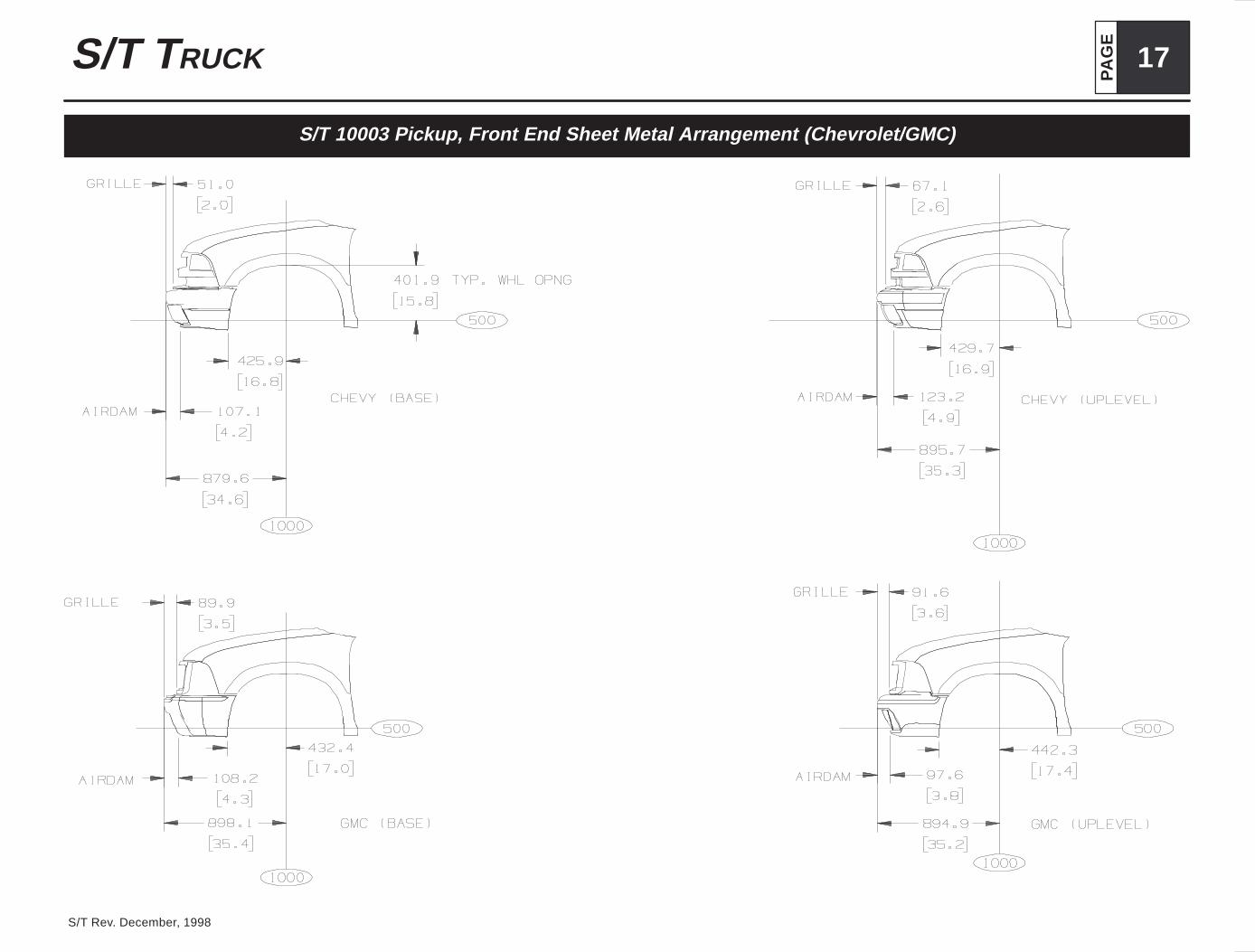
S/T 10003 Pickup, Front End Sheet Metal Arrangement (Chevrolet/GMC)

PA
GE18 S/T TRUCK
S/T Rev. 12/98
S/T 10000 Pickup, Front End Sheet Metal Arrangements (Isuzu/Bravada)

PA
GE
19S/T TRUCK
S/T Rev. December, 1998
S/T 10003 Pickup, Cab Profile

PA
GE20 S/T TRUCK
S/T Rev. 12/98
S/T 100(03, 53) Pickup Box

PA
GE
21S/T TRUCK
S/T Rev. 12/98
S/T 100(03, 53) Pickup Box, Top Rail

PA
GE22 S/T TRUCK
S/T Rev. 12/98
S/T 100(03, 53) Pickup Box, Interior

PA
GE
23S/T TRUCK
S/T Rev. 12/98
S/T 100(03, 53) Pickup Box Sportside

PA
GE24 S/T TRUCK
S/T Rev. 12/98
S/T 100(03, 53) Pickup Box Sportside, Top Rail

PA
GE
25S/T TRUCK
S/T Rev. 12/98
S/T 100(03, 53) Pickup Box Sportside, Interior

PA
GE26 S/T TRUCK
S/T Rev. 12/98
S/T 10506–4 Door Utility, Exterior with End Gate, General Arrangement

PA
GE
27S/T TRUCK
S/T Rev. 12/98
S/T 10506–4 Door Utility, Exterior with Lift Gate, General Arrangement

PA
GE28 S/T TRUCK
S/T Rev. 12/98
S/T 10516–2 Door Utility, Exterior, General Arrangement
PA
GE
29S/T TRUCK
S/T Rev. 12/98
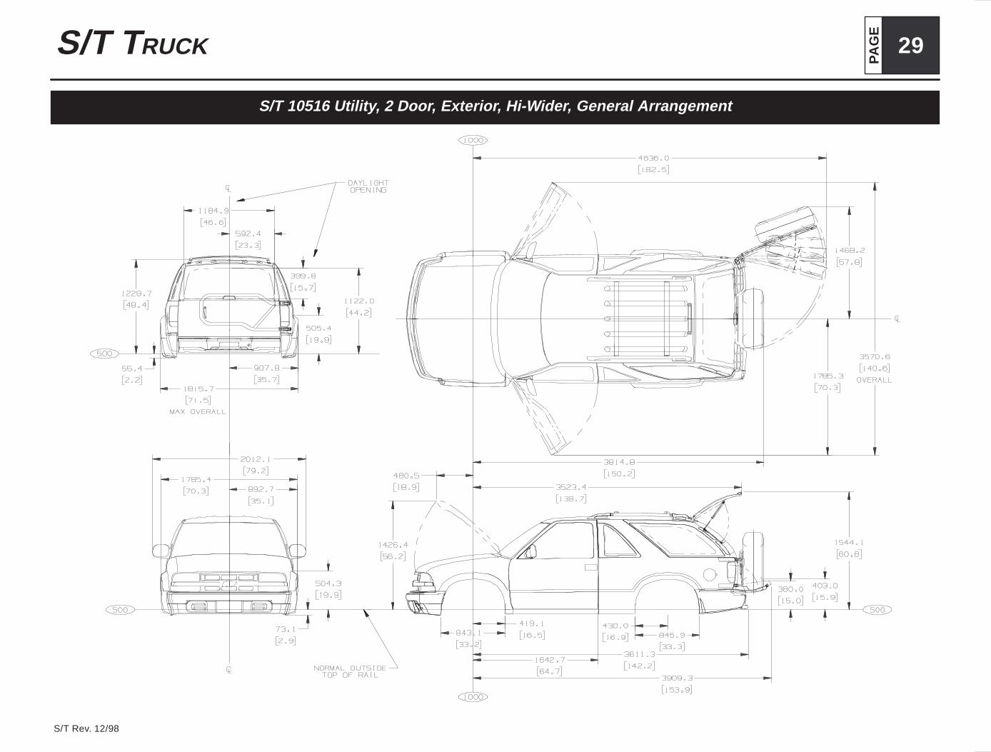
S/T 10516 Utility, 2 Door, Exterior, Hi-Wider, General Arrangement

PA
GE30 S/T TRUCK
S/T Rev. 12/98
S/T 10(6/8)03 Pickup, Regular Cab, Interior
PA
GE
31S/T TRUCK
S/T Rev. December, 1998
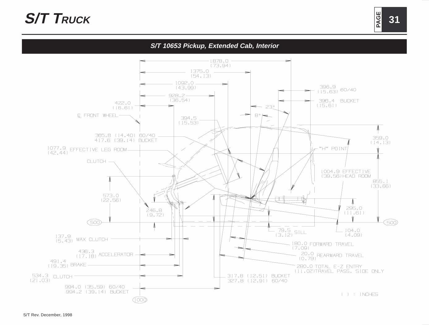
S/T 10653 Pickup, Extended Cab, Interior

PA
GE32 S/T TRUCK
S/T Rev. 12/98
S/T 10003 Pickup, Interior Seating

PA
GE
33S/T TRUCK
S/T Rev. December, 1998
S/T 10516–2 Door Utility, Interior Seating

PA
GE34 S/T TRUCK
S/T Rev. 12/98
S/T 10506–4 Door Utility, Interior Seating

PA
GE
35S/T TRUCK
S/T Rev. December, 1998
S 10603 Pickup, 2 Wheel Drive, Crossmember Arrangement

PA
GE36 S/T TRUCK
S/T Rev. 12/98
T 10603 Pickup, 4 Wheel Drive, Crossmember Arrangement

PA
GE
37S/T TRUCK
S/T Rev. December, 1998
S 10803 Pickup, 2 Wheel Drive, Crossmember Arrangement

PA
GE38 S/T TRUCK
S/T Rev. 12/98
T 10803 Pickup, 4 Wheel Drive, Crossmember Arrangement

PA
GE
39S/T TRUCK
S/T Rev. 12/98
S 10653 Pickup, 2 Wheel Drive, Crossmember Arrangement
PA
GE40 S/T TRUCK
S/T Rev. 12/98
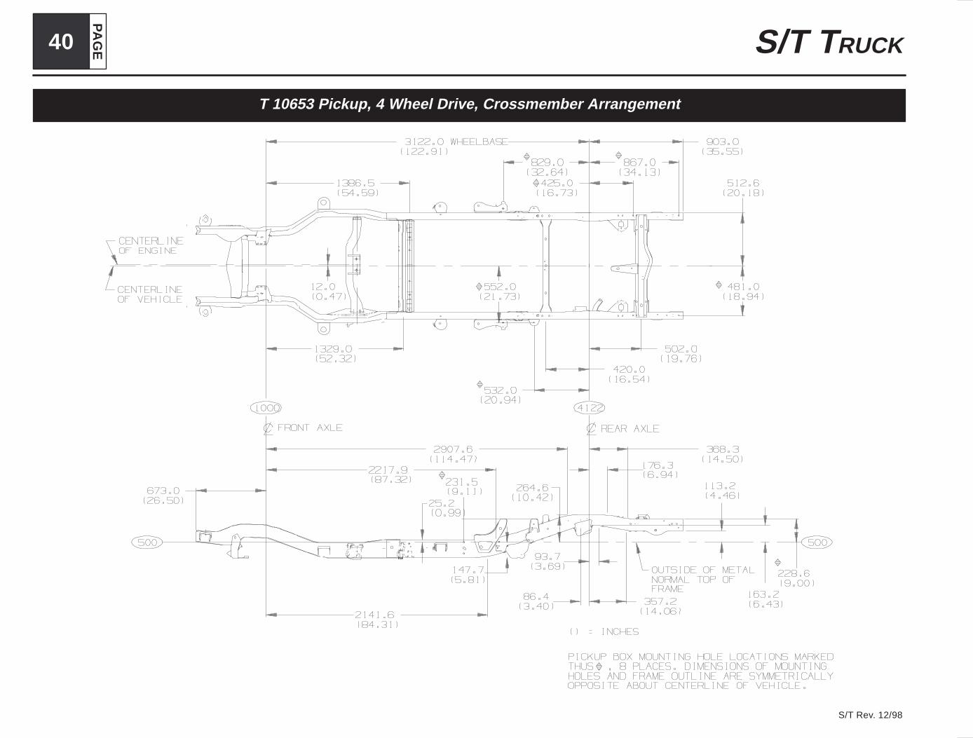
T 10653 Pickup, 4 Wheel Drive, Crossmember Arrangement

PA
GE
41S/T TRUCK
S/T Rev. 12/98
S 10506 Utility, 2 Wheel Drive, Crossmember Arrangement

PA
GE42 S/T TRUCK
S/T Rev. 12/98
T 15506 Utility, 4 Wheel Drive, Crossmember Arrangement

PA
GE
43S/T TRUCK
S/T Rev. 12/98
S 10516 Utility, 2 Wheel Drive, Crossmember Arrangement

PA
GE44 S/T TRUCK
S/T Rev. 12/98
T 10516 Utility, 4 Wheel Drive, Crossmember Arrangement

PA
GE
45S/T TRUCK
S/T Rev. 12/98
S/T 100(03, 53) Pickup, Spare Tire Carrier

PA
GE46 S/T TRUCK
S/T Rev. 12/98
S/T 10506–4Door Utility, Spare Tire Carrier

PA
GE
47S/T TRUCK
S/T Rev. 12/98
S/T 105(06, 16) Utility, Trailer Hitch Mounting

PA
GE48 S/T TRUCK
S/T Rev. 12/98
S 10000 Front Axle/Tire Data Chart

PA
GE
49S/T TRUCK
S/T Rev. 12/98
T 10000 Front Axle/Tire Data Chart

PA
GE50 S/T TRUCK
S/T Rev. 12/98
S/T 10003 Pickup, Rear Axle/Tire Data Chart

PA
GE
51S/T TRUCK
S/T Rev. 12/98
S/T 105(06, 16) Utility, Rear Axle/Tire Data Chart

PA
GE52 S/T TRUCK
S/T Rev. 12/98
S/T 100(03, 53) Pickup

PA
GE
53S/T TRUCK
S/T Rev. 12/98
S/T 10506 Utility 4 Door
PA
GE54 S/T TRUCK
S/T Rev. 12/98
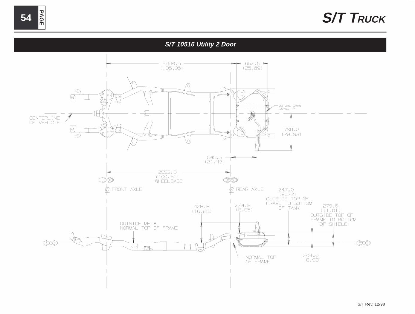
S/T 10516 Utility 2 Door

PA
GE
55S/T TRUCK
S/T Rev. 12/98
S 100(03, 53) Pickup, Gas Engine 2.2L L4, Option LN2

PA
GE56 S/T TRUCK
S/T Rev. 12/98
S 100(03, 53) Pickup, Gas Engine 4.3L V6, Option LB4–ZR2

PA
GE
57S/T TRUCK
S/T Rev. 12/98
T 100(03, 53) Pickup, Gas Engine 4.3L V6, Option LB4–ZR2

PA
GE58 S/T TRUCK
S/T Rev. 12/98
T 106(03, 53) Hi-Wider Pickup, Gas Engine 4.3L V6, Option LB4 & ZR2

PA
GE
59S/T TRUCK
S/T Rev. 12/98
S 10506–4 Door Utility, Gas 4.3L V6, Option LB4

PA
GE60 S/T TRUCK
S/T Rev. 12/98
T 10506–4 Door Utility, Gas 4.3L V6, Option LB4

PA
GE
61S/T TRUCK
S/T Rev. 12/98
S 10516–2 Door Utility, Gas Engine 4.3L V6, Option LB4

PA
GE62 S/T TRUCK
S/T Rev. 12/98
T 10516–2 Door Utility, Gas Engine 4.3L V6, Option LB4

PA
GE
63S/T TRUCK
S/T Rev. 12/98
Ordering Information
Electrical diagrams are available from Chevrolet and GMC through service publica-tions. They have contracted the following companies to handle the ordering and ship-ping of the manuals.
Helm Inc.P.O. Box 07130Detroit, Michigan 48207
1 (313) 865-5000 for information and inquiries1 (800) 782-4356 for credit card orders
Routine orders will be shipped within 10 days of receipt. Rush orders will be accom-modated for an additional charge.
Order forms are available upon request and orders can be paid by check or moneyorder, made payable to the mentioned companies. Credit Card orders can be madeby phone on the listed toll free phone numbers.

PA
GE64 S/T TRUCK
S/T Rev. 12/98
Notes