wheelset structural flexibility andrack t flexibility in ...11913/fulltext01.pdf · • a...
TRANSCRIPT

Doctoral Thesis
TRITA AVE 2007:17
ISSN 1651-7660
ISBN 978-91-7178-636-4
Wheelset Structural Flexibility
and Track Flexibility
in Vehicle-Track Dynamic Interaction
by
Nizar Chaar
Postal addressRail Vehicles
Visiting address Telephone E-mail
Aeronautical and Vehicle EngineeringRoyal Institute of Technology (KTH)SE-100 44 StockholmSweden
Teknikringen 8Stockholm
+46 8 790 84 76Fax+46 8 790 76 29

.

Wheelset Structural Flexibility and Track Flexibility in Vehicle-Track Dynamic Interaction
Preface and acknowledgements
This thesis summarizes the work I have carried out during my doctoral studies at theDivision of Rail Vehicles, Department of Aeronautical and Vehicle Engineering, at theRoyal Institute of Technology (KTH).
This work, which is part of the SAMBA1 research programme, investigates the influenceof the wheelset structural flexibility and track flexibility on the vehicle-track dynamicinteraction.
In this context, I would like to express my sincere gratitude to my supervisor Prof. MatsBerg for his encouragement, help, assistance, and support throughout these years. I alsowould like to thank Prof. Evert Andersson for his support and valuable advice as well asmy colleagues at the department for the friendly atmosphere they maintained duringthese last few years.
I also would like to thank the staff at the Marcus Wallenberg Laboratory for Sound andVibration Research (MWL) for their help and assistance during the experimental modalanalysis, Ingemar Persson at DEsolver AB for his advice and support with the softwareGENSYS, Interfleet Technology and Banverket for their help and assistance theyprovided with the on-track, respectively track flexibility and irregularity measurements.
Likewise, I am very grateful for the support and assistance I received from all themembers of the project reference group and for the financial support from Banverket(Swedish National Rail Administration), Bombardier Transportation (Sweden),Interfleet Technology (Sweden), Tågoperatörerna (Association of Swedish TrainOperators) and SL (Stockholm Transport).
Last but not least I would like to thank my parents for their support and my wife for herhelp and understanding especially during the last year.
Stockholm, April 2007
Nizar Chaar
1. SAMBA, in Swedish, is an abbreviation for “Samverkan Fordon-Bana” or, in English, Vehicle-TrackInteraction.
i


Wheelset Structural Flexibility and Track Flexibility in Vehicle-Track Dynamic Interaction
AbstractThis thesis investigates the influence of wheelset structural flexibility and trackflexibility on the vehicle-track dynamic interaction, mainly in terms of wheel-rail forcesup to 200 Hz, using simulations and measurements.
The previous knowledge in this field is first reviewed and summarized, then two casestudies are selected for investigation. The first case study involves a locomotive runningon a tangent track section at a speed of 140 km/h, while the second one deals with anewly designed motor coach running at two adjacent and tangent track sections withdifferent track components and at speeds up to 280 km/h.
For the locomotive case study, the wheelset dynamic properties are first investigatedthrough experimental modal analysis (EMA) for a frequency range of 0-500 Hz,assuming free boundary conditions. The EMA results showed relatively low wheelseteigenfrequencies. A three-dimensional finite element (FE) model, which also includesthe wheelset gear-box, is then developed and validated against the measurements forfrequencies up to 200 Hz with good agreement. The FE results displayed a significantinfluence of the wheels’ flexibility on the wheelset’s total structural flexibility.
In order to assure proper representation of the track flexibility the vertical and lateraldynamic track properties at a sleeper are measured through a special vehicle at standstill,and measured track irregularities are used. In the numerical simulations, the wheelsetstructural flexibility is introduced using the calculated eigenmodes above while so-calledmoving track models are used to model the track flexibility. The simulated wheel-railforces are then validated against measured ones obtained from corresponding on-trackmeasurements. Results from the simulations highlight the importance of proper trackflexibility modelling and track data and also show a significant influence of the wheelsetstructural flexibility on the lateral track forces.
For the motor coach case study, the wheelset dynamic properties are determined throughnumerical modal analysis using a rather simple FE model and a number of eigenmodesare then introduced in the simulations. The vertical and lateral track dynamic propertiesat selected track sections are measured using the standstill technique but rolling stiffnessmeasurements, where the vertical track flexibility in the frequency range 5-50 Hz ismeasured continuously along the track, are also included. The track flexibility isintroduced through moving track models. Measured track irregularity and vertical trackroughness are also considered.
Basic numerical simulations, where the calculated track forces are compared tomeasured ones, are first performed and followed by a set of parametric studies. Theresults display a significant influence of the track flexibility on vertical wheel-rail forcesfor frequencies above 80 Hz, with higher forces for the stiffer track (but weaker rails).The effect of wheelset structural flexibility on the lateral force is also confirmed. Theparametric studies highlight the importance of track flexibility modelling and show thatmodifications of the vertical track receptance, motivated by uncertainties in the pertinentmeasurements, can improve the simulated forces.
Keywords: Vehicle-track dynamic interaction, wheelset structural flexibility,experimental modal analysis, track flexibility, moving track models, track irregularity,track roughness, measurements, simulations, wheel-rail forces, parametric studies.
iii

Wheelset Structural Flexibility and Track Flexibility in Vehicle-Ttrack Dynamic Interaction
Outline of the thesis
This thesis consists of an introduction and four papers. The introduction reviews thecurrent research field and summarizes the present work. The four papers are:
Paper A
Chaar N and Berg M: Experimental and numerical modal analyses of a loco wheelset,Proceedings of the 18th IAVSD Symposium on dynamics of vehicles on roads and ontracks, Vehicle System Dynamics Supplement, 41 (2004), pp. 597-606.
Paper B
Chaar N and Berg M: Vehicle-track dynamic simulations of a locomotive consideringwheelset structural flexibility and comparison with measurements, Proc IMechE Part F:Journal of Rail and Rapid Transit, Vol. 219, pp. 225-238, December 2005.
Paper CChaar N and Berg M: Simulation of vehicle-track interaction with flexible wheelsets,moving track models and field tests, Proceedings of the 19th IAVSD Symposium ondynamics of vehicles on roads and on tracks, Vehicle System Dynamics Supplement, 44(2006), pp. 921-931.
Paper DChaar N and Berg M: Dynamic wheel-rail force measurements and simulations of ahigh-speed train running on two tracks with different flexibility and irregularities,submitted for publication.
Chaar carried out the experimental and numerical modal analyses of the wheelsets,specified and evaluated the track flexibility measurements, performed the on-tracksimulations and wrote the appended papers.
Berg supervised the work and reviewed the documentation.
The track flexibility measurements were performed by Banverket while InterfleetTechnology carried out the on-track measurements.
The locomotive multibody dynamics model with rigid wheelsets was obtained fromInterfleet Technology. The model of the Regina coach was developed by BombardierTransportation and remodelled according to recent bogie modifications by Chaar.
v


Wheelset Structural Flexibility and Track Flexibility in Vehicle-Track Dynamic Interaction
Thesis contributions
This thesis provides the following contributions to the present research field:
• A literature review on methods used in measuring and modelling the wheelsetstructural flexibility and track flexibility is provided. Also, the influence of theseflexibilities on the overall vehicle-track dynamic interaction is included.
• The wheelsets investigated are neither symmetrical nor axisymmetrical, a circum-stance that is very rare in previous studies.
• The dynamic properties are investigated for two different wheelsets: The firstwheelset pertaining to a locomotive is rather slender and heavy due to its large wheeldiameter and heavy gear-box. In contrast, the second wheelset pertaining to a motorcoach has a smaller wheel diameter and a lighter gear-box.
• A detailed finite element model of the locomotive wheelset, including traction gearand axle-boxes, is developed and validated against measurements for the frequencyrange of 0-200 Hz.
• Vertical and lateral dynamic track properties are measured for given preloads atdifferent track sections having different track components and at a frequency range of0-200 Hz. This enables a proper assessment of the influence of the track flexibilityand track components on the wheel-rail forces.
• The vertical track properties are also investigated using the rolling stiffness techniquein the frequency range of 5-50 Hz.
• A set of moving track models are developed and used in the vehicle-track dynamicsimulations. The track model data are chosen so as to get good agreement with themeasured track receptances above.
• The sleeper passing effect is represented in the simulations by varying the trackparameters along the track.
• Measured track irregularities are considered in the simulations over a widewavelength interval, also including track roughness.
• The influence of the wheelset structural flexibility and track flexibility on wheel-railforces is investigated in the frequency range of 0-200 Hz for two case studies. Thisrange stands in contrast to traditional vehicle-track interaction analysis, whichtypically cover frequencies up to 20 Hz only, and studies detailing the track behaviourwith the main interest on frequencies in the range of 500-1500 Hz.
• The calculated track forces are validated against forces from on-track measurementsenhancing the credibility of the present work.
vii

Contents
Preface and acknowledgements.......................................................................................i
Abstract .......................................................................................................................... iii
Outline of the thesis .........................................................................................................v
Thesis contributions ..................................................................................................... vii
1 Introduction.................................................................................................................1
1.1 Vehicle-track dynamic interaction ...........................................................................11.2 Wheelset structural flexibility ..................................................................................11.3 Track flexibility........................................................................................................21.4 Track irregularity and roughness .............................................................................41.5 This thesis ................................................................................................................5
2 Wheelset structural flexibility....................................................................................7
2.1 Measurements of wheelset structural flexibility ......................................................72.2 Modelling of wheelset structural flexibility...........................................................122.3 Influence of wheelset structural flexibility ............................................................20
3 Track flexibility .........................................................................................................27
3.1 Measurements of track flexibility ..........................................................................273.2 Modelling of track flexibility.................................................................................333.3 Influence of track flexibility ..................................................................................35
4 The present work ......................................................................................................37
4.1 Introduction............................................................................................................374.2 Summary of Paper A..............................................................................................374.3 Summary of Paper B ..............................................................................................384.4 Summary of Paper C ..............................................................................................394.5 Summary of Paper D..............................................................................................41
5 Conclusions and future work...................................................................................43
References.......................................................................................................................45
Paper A to D
ix


Wheelset Structural Flexibility and Track Flexibility in Vehicle-Track Dynamic Interaction
1 Introduction
1.1 Vehicle-track dynamic interaction
The last decades have witnessed a substantial development of high-speed trains such asTGV in France, ICE in Germany, Pendolino in Italy, Shinkansen in Japan and X2000 inSweden. Moreover, current research activities are focusing on new methods to increasetrain speed and capacity and, in particular, on improving the vehicle-track dynamicinteraction.
Vehicle-track interaction is a broad and multi-disciplinary subject that deals with ridecomfort and safety, vehicle stability, wheel-rail forces, wheel-rail corrugation, wheelout-of-roundness, noise propagation, etc., and is influenced by a variety of factors. Whilenumerical simulations are considered a fast and inexpensive tool for investigating themain sources and causes of the vehicle-track dynamic interaction, on-trackmeasurements are still seen as the most reliable approach for approval of vehicles undervarious operational conditions. These measurements are regulated through specificstandards, e.g. UIC 518 [13] and EN 14363 [5], which in turn present some unresolvedtopics requiring continuous and further review. An example of such an unsettled issue isthe 20 Hz cut-off frequency of the low-pass filtering which may be appropriate forexamining the ride safety and comfort, but might be too forgiving for wheel-rail forcesand pertinent damage mechanisms like fatigue.
In this context, the wheelset structural flexibility and track flexibility are two importantfactors known to influence the vehicle-track interaction forces at frequencies above 20Hz. The following sections present a brief description of a conventional railway wheelsetand track, provide an overview over the wheelset structural flexibility, track flexibilityand track irregularity, and give an outline of the current study.
1.2 Wheelset structural flexibility
A conventional wheelset consists of two conical wheels rigidly connected to a commonwheelset axle, axle-boxes mounted on the two axle ends through roller bearings, andoften axle-mounted or wheel-mounted brake discs. In case of a powered wheelset, anaxle gear wheel is fixed to the wheelset and a gear-box is mounted on the wheelset axlethrough a roller bearing.
The wheelset forms an important entity of a railway vehicle. It helps carrying the vehiclethrough the primary suspension, supports the vehicle at rolling, guides the vehicle,transfers the longitudinal forces at braking and in case of a powered wheelset, at traction.A general review of the wheelset behaviour and functions can be found in [3], [7], [10],[12] and [14]. Since wheelsets are more prone to show fatigue and stress relatedproblems, several guidelines were specifically developed to design the wheelsets andtheir components. Some of these codes are reviewed in [30].
According to Popp et al. [66], the wheelset is by far the most interesting component ofthe vehicle in the frequency range of 50-500 Hz as a result of its running behaviour andelastic deformation. Like all mechanical structures, wheelsets have structural flexibilityand natural frequencies. The wheelset is deformed due to its dead weight and when
1

Introduction
subjected to external forces via its axle-boxes, brake discs and axle gear wheel as well asthrough the rails (track). The dynamic contributions to the wheel-rail forces mainlyoriginate from wheel and track irregularities. In some designs a local wheelset flexibilityis introduced as for resilient wheels or independently rotating wheels, see also [30]. Thiskind of local flexibility is not considered in this study. An example of wheelset structuralflexibility, showing the wheelset’s first bending mode at free boundary conditions, isillustrated in Figure 1-1.
Figure 1-1 Example of wheelset structural flexibility; first bending mode [47].
Several studies have investigated the influence of the wheelset structural flexibility onvehicle-track dynamic interaction. In short, the wheelset elastic deformation can affectthe vehicle lateral stability, cause fluctuations in the wheel-rail forces, contribute to thedevelopment of wheel-rail corrugation and wheel out-of roundness, and lead to noisepropagation in tight curves. Yet researchers, such as Popp et al. [66], agreed that theknowledge regarding the influence of the wheelset structural flexibility in the frequencyrange 50-500 Hz is rather poor. See also Chapter 2.
1.3 Track flexibility
Railway tracks play also an important role in supporting and guiding the rolling vehiclesin a safe and economic manner. Tracks can be divided into two types: ballasted and non-ballasted (slab tracks). The track superstructure components can also differ significantlywith regards to their geometrical, material and physical properties, see also [3].
A typical ballasted track, shown here in Figure 1-2, is composed of two steel railsmounted on concrete or wooden sleepers through fasteners. Plastic or rubber rail pads areusually located between the sleepers and the rails. The sleepers are embedded in a ballastlayer which in turn is resting on subballast and subgrade.
2

Wheelset Structural Flexibility and Track Flexibility in Vehicle-Track Dynamic Interaction
Figure 1-2 Main components of a ballasted track, based on [90].
Likewise, the track dynamic properties are of great interest since the vertical and lateraltrack flexibilities are known to influence the wheel-rail forces and induce oscillations ofthe wheels and rails [3]. In this context, the types of track components play an importantrole for the overall track dynamic properties, [96]. For instance, soft rail pads isolate thehigh frequency vibrations and their transmission down to sleeper and ballast, while stiffrail pads give more direct transmission of axle load, including the high-frequencyvibration, [91] and [92]. Therefore, measurement of track flexibility is quite importantand useful since it can quantify weak spots of the tracks, verify newly built tracks,identify places with excessive sources of vibrations, etc., [88].
Track flexibility is generally defined as the ratio between the track displacement and thepertinent load and can be assessed through rolling or standstill measurements. Thesetechniques are illustrated and reviewed by Berggren [87], and briefly described inChapter 3 of this thesis. For the standstill technique, one way to investigate the dynamicproperties of a railway track is to first preload the track vertically and then load the trackdynamically through its rails with a sinusoidal force. At frequencies up to about 200 Hz,this can be done by using hydraulic cylinders. The results are often presented in the formof track receptance, or the complex-valued ratio of dynamic track displacement over thedynamic force. Due to non-linear track properties such as load-dependent behaviour ofrail pads and ballast, the receptance is not only dependent on the excitation frequency,but also on the static preload and dynamic amplitude. Figure 1-3 exemplifies the verticaland lateral receptance magnitudes measured for two static preloads, showing a higherrecpetance (lower stiffness) for the lowest preload. The lateral track receptance is higher(lower stiffness) than the vertical one, and has a clear resonance at 80 Hz.
In addition, the track properties can be dependent on the season, a frozen track beingstiffer than a non-frozen one, [3].
Due to the varying subgrade conditions and ballast compaction, the track dynamicproperties differ along the track, even between two adjacent sleepers. A special variationin track flexibility along the track arises through the discrete positions of the sleepers.This relatively small additional rail deflection between any two sleepers can give rise tolarge wheel-rail force fluctuations. This phenomenon is referred to as sleeper passingeffect and the corresponding frequency is termed sleeper passing frequency, see also [3]and [103]. Variations in track dynamic properties also arise at switches and turnouts [91],and at tunnels and bridges due to a stiffer foundation.
3

Introduction
Figure 1-3 Example of measured vertical and lateral track receptances asmagnitude, at 50 and 90 kN static preload per rail and at the samedynamic amplitude “50%”, [89].
Once the track is loaded by the vehicle, system resonance frequencies occur. An exampleof such a resonance is the so-called P2 resonance where the wheelset vibrates verticallyon the track, see also [41]. The vehicle is subjected to different sources of excitation, onebeing the variations of track flexibility along the track described above. Trackirregularities and roughness present another major excitation source, see below.
1.4 Track irregularity and roughness
Track misalignments often constitute the main source of excitation for vehicle-tracksystems. According to [91] and [3], four different types of geometric errors, orirregularities can be identified. These errors are the lateral, vertical, gauge and cantmisalignments, see Figure 1-4. Long wavelength irregularities cause nuisance anddiscomfort whereas short wavelength irregularities, often called roughness, result intohigh levels of noise and vibration.
Figure 1-4 Vertical, lateral, cant and gauge irregularities, [3].
4

Wheelset Structural Flexibility and Track Flexibility in Vehicle-Track Dynamic Interaction
Measurement of track irregularities is an important indicator for condition assessmentand monitoring of railway tracks, [87]. The track irregularities are usually measured viaspecial measurement vehicles [3], and relevant standards are developed to regulate thesemeasurements and set the required limit values for different wavelength intervals. Thesuggested interval in the code UIC 518 [13] is λ = 3-25 m, which eliminates the high-frequent track forces and hence may be forgiving with regards to wheel and rail damage.For instance, for a speed of v = 100 km/h (27.8 m/s) the frequency range is f = 1.1-9.3Hz, whereas for v = 275 km/h (76.4 m/s) the frequency range is f = 3.1-25.5 Hz, seeFigure 1-5.
Figure 1-5 Excitation frequency as a function of track irregularity wavelength forthree different speeds (f = v/λ). The UIC 518 wavelength range 3-25 mis indicated.
1.5 This thesis
This thesis investigates the influence of the wheelset structural flexibility and trackflexibility on wheel-rail forces in the frequency range of 0-200 Hz using simulations andmeasurements.
Chapter 2 reviews wheelset structural flexibility measurements and models andhighlights the major effects of this flexibility on the vehicle-track interaction.
Chapter 3 briefly surveys track flexibility measurements methods and results, illustratesdifferent types of track flexibility models, and examines the influence of the trackflexibility on the vehicle-track dynamic behaviour.
Chapter 4 introduces the author’s work and gives a summary of the four appendedpapers.
Chapter 5 presents the conclusions and suggestions on future work.
Finally, a reference list is included.
5

Introduction
6

Wheelset Structural Flexibility and Track Flexibility in Vehicle-Track Dynamic Interaction
2 Wheelset structural flexibility
This chapter briefly reviews measurement methods and results of wheelset structuralflexibility, common wheelset structural flexibility models and the major effects of thisflexibility on the vehicle-track dynamic interaction. These topics were also examined indetail in [30].
2.1 Measurements of wheelset structural flexibility
Experimental modal analysis: Free boundary conditionsExperimental modal analysis (EMA) is generally used in assessing the wheelset modalparameters (eigenfrequencies, eigenmodes and relative damping) through measuredfrequency response functions (FRF) and assuming a linear, time-invariant system, [4]and [8]. During the experiments, “Free” or “Supported” boundary conditions can beimplemented. Free boundary conditions can be achieved by suspending the wheelsetfreely through soft springs. This section reviews some cases where the wheelset modalparameters were extracted through EMA and lists the major findings.
EMA involving several types of non-powered wheelsets was carried out by Tassilly andVincent, [77]. During the measurements the axle was connected to the bogie and thebogie was held on specific supports so that the excited wheelset did not contact the rails.The wheelset was excited by an electro-magnetic shaker using stepped-sine ranging for20-400 Hz. Several driving points were selected: two points in the vertical direction tostudy the influence of the contact patch position, one point in the transverse direction andone point in the longitudinal direction, Figure 2-1. The authors confirmed a strongcoupling between vertical and transverse directions at the contact point. On the otherhand, the coupling between the longitudinal direction and the two other directions wasvery weak. The resulting eigenfrequencies and eigenmodes are shown in Figure 2-2 andsummarized in Table 2-1.
Figure 2-1 Vertical and lateral driving points of a non-powered wheelsetinvestigated in [77].
7
Wheelset structural flexibility
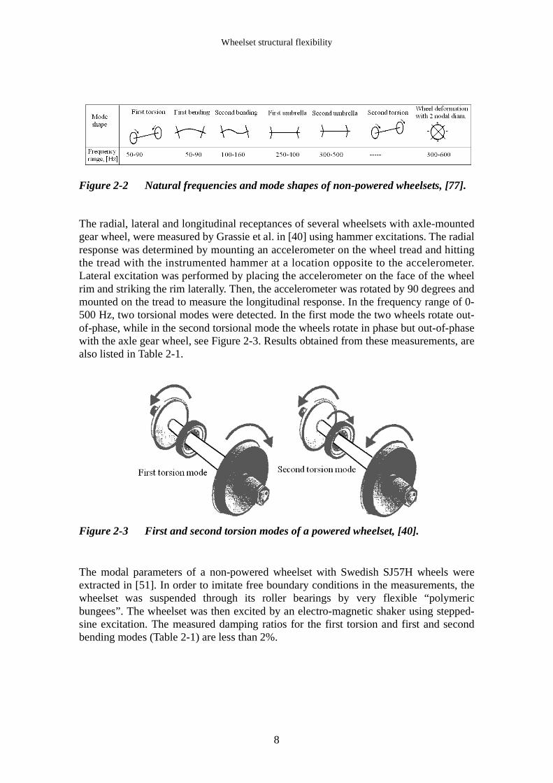
Figure 2-2 Natural frequencies and mode shapes of non-powered wheelsets, [77].
The radial, lateral and longitudinal receptances of several wheelsets with axle-mountedgear wheel, were measured by Grassie et al. in [40] using hammer excitations. The radialresponse was determined by mounting an accelerometer on the wheel tread and hittingthe tread with the instrumented hammer at a location opposite to the accelerometer.Lateral excitation was performed by placing the accelerometer on the face of the wheelrim and striking the rim laterally. Then, the accelerometer was rotated by 90 degrees andmounted on the tread to measure the longitudinal response. In the frequency range of 0-500 Hz, two torsional modes were detected. In the first mode the two wheels rotate out-of-phase, while in the second torsional mode the wheels rotate in phase but out-of-phasewith the axle gear wheel, see Figure 2-3. Results obtained from these measurements, arealso listed in Table 2-1.
Figure 2-3 First and second torsion modes of a powered wheelset, [40].
The modal parameters of a non-powered wheelset with Swedish SJ57H wheels wereextracted in [51]. In order to imitate free boundary conditions in the measurements, thewheelset was suspended through its roller bearings by very flexible “polymericbungees”. The wheelset was then excited by an electro-magnetic shaker using stepped-sine excitation. The measured damping ratios for the first torsion and first and secondbending modes (Table 2-1) are less than 2%.
8

Wheelset Structural Flexibility and Track Flexibility in Vehicle-Track Dynamic Interaction
In addition, EMA of a wheelset assuming free boundary conditions were performed inthe following studies:
• In [59], where the case studied involved a wheelset pertaining to an ICE-1 coach withfour axle-mounted brake discs, see corresponding results in Table 2-1.
• In [80] where the modal parameters of a non-powered wheelset with two axle-mounted brake discs pertaining to a Swedish X2000 train were extracted.
Table 2-1 lists some mode shapes and pertinent eigenfrequencies obtained from EMAassuming free boundary conditions. Frequencies as low as 50 Hz can be identified.
Table 2-1 Examples of measured wheelset eigenmodes and eigenfrequencies, [Hz].
In some situations, the natural frequencies and mode shapes of a single railway wheelwere measured. Examples of such studies are Cervello et al. [29] and Kämmerling [48].In [48] the wheel was placed horizontally with its outer side resting on two car tyres, seeFigure 2-4. This elastic support gives, according to the author, only a small influence onthe intended free wheel vibrations.
Figure 2-4 Experimental modal analysis of a free wheel, [48].
Ref. Wheelset typeFirst torsion
First bending
Second bending
First umbrella
Second umbrella
Second torsion
2 nodal diam.
[35] ETR500, no brake discs
---- 79 130 ----- ----- ---- ----
[40] Powered transit wheelsets
50-70 60-80 ----- ----- ----- 290-500 ----
[51] Non-powered SJ57H wheelset
----- 84 152.5 249 397 ------ ----
[59] ICE, 4 axle-mounted discs
96 82 162 ----- ----- 289 ---
[77] Non-powered wheelsets
50-90 50-90 100-160 250-400 300-500 ---- 300-600
9
Wheelset structural flexibility
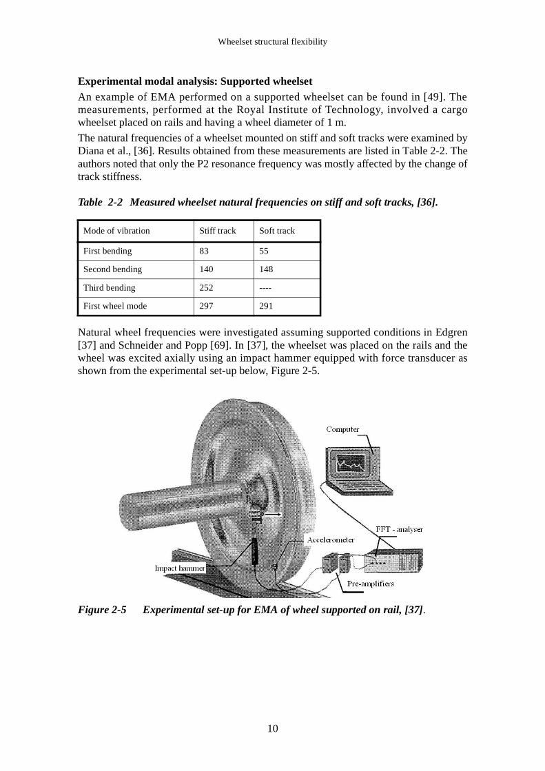
Experimental modal analysis: Supported wheelsetAn example of EMA performed on a supported wheelset can be found in [49]. Themeasurements, performed at the Royal Institute of Technology, involved a cargowheelset placed on rails and having a wheel diameter of 1 m.
The natural frequencies of a wheelset mounted on stiff and soft tracks were examined byDiana et al., [36]. Results obtained from these measurements are listed in Table 2-2. Theauthors noted that only the P2 resonance frequency was mostly affected by the change oftrack stiffness.
Table 2-2 Measured wheelset natural frequencies on stiff and soft tracks, [36].
Natural wheel frequencies were investigated assuming supported conditions in Edgren[37] and Schneider and Popp [69]. In [37], the wheelset was placed on the rails and thewheel was excited axially using an impact hammer equipped with force transducer asshown from the experimental set-up below, Figure 2-5.
Figure 2-5 Experimental set-up for EMA of wheel supported on rail, [37].
Mode of vibration Stiff track Soft track
First bending 83 55
Second bending 140 148
Third bending 252 ----
First wheel mode 297 291
10

Wheelset Structural Flexibility and Track Flexibility in Vehicle-Track Dynamic Interaction
On-track measurements: instrumented wheelsets and codes/regulations
On-track measurements can describe the dynamic behaviour of the vehicle on the track.These measurements are carried out using instrumented wheelsets and are often linked torelevant codes such as UIC 518 [13], see also Chapter 1. Measured data such as wheel-rail forces and axle-box accelerations are gathered through strain gauges usually placedon the wheel web and accelerometers mounted on the axle-boxes. For proper results andplacement of the strain gauges, see Figure 2-6, the instrumented wheelsets have S-shaped wheels and possible wheel-mounted brake discs are removed. More informationregarding instrumented wheelsets can be found in [3], [19] and [80].
Figure 2-6 Principal design of an instrumented wheelset for force measurements,[19].
The code UIC 518 [13] has set the rules that must be met when conducting dynamicbehaviour tests in connection with safety, track fatigue and running behaviour. Thespecifications have set the cut-off frequency for the low-pass filtering of the track forces.As mentioned in Chapter 1, the cut-off frequency suggested is 20 Hz which means thatthe load variations due to the sleeper passing effect and the main wheelset vibrations willbe filtered out, even though such variations can be very high.
Figure 2-7 illustrates an example of measured vertical wheel-rail forces of an X2000power unit on fairly rough track at high speed curving. The figure depicts two filteringprocedures and clearly shows major force differences for the two cut-off frequencies of30 and 90 Hz.
11

Wheelset structural flexibility
Figure 2-7 Measured vertical wheel-rail force of an X2000 power unit at high-speed curve negotiation, [19].
2.2 Modelling of wheelset structural flexibility
Most researchers agree that the wheelset structural flexibility must be considered in themid- and high-frequency ranges (i.e. 50-500 Hz and 500 Hz to 20 kHz [66]), since thisflexibility can influence the vehicle-track dynamic behaviour. A rigid wheelset modelcan be appropriate for the low-frequency range (below 50 Hz), where the ride comfortand stability are of main interests, [35], [66], [68] and [71]. The introduction of thewheelset structural flexibility allows also for the determination of different quantitiessuch as strains and stresses [18], and in some cases it is used to avoid numericalproblems in the simulations due to a rigid connection between the axle and the track,[20].
According to [66], the methods used in modelling the wheelset structural flexibility are:continuous, finite element (FE) and lumped models. These methods are detailed andreviewed in [27]. The wheelset flexibility is then usually considered in the numericalsimulations through eigenmodes derived from the respective models or from other
12

Wheelset Structural Flexibility and Track Flexibility in Vehicle-Track Dynamic Interaction
reduced wheelset models, see also [1]. The choice of the wheelset flexibility model andnumber of degrees of freedom (dof) depends on the frequency range of interest and onthe number of wheelset mode shapes in that range.
Continuous modelsIn these models, the wheelset’s geometry is represented by means of different continuapossibly with additional discrete elements. For an appropriate representation of thewheelset flexibility in the mid- and high-frequency ranges, continuous models shouldinclude among others, a realistic distribution of mass and inertia along the wheelset, thethree-dimensional deformation of the axle including bending and torsion, the out-of-plane wheel deformation, and gyroscopic effects [66].
A two-dimensional continuous wheelset model was developed by Szolc, [71]. The modelaccounts for the wheelset bending, torsional and lateral vibrations in the frequency rangeof 30-300 Hz. The model is shown in Figure 2-8 and consists of a wheelset axlerepresented by an axially rigid and torsionally deformable beam, whereas the wheels andthe brake discs are represented by rigid rings attached to the axle through a massless,elastically isotropic membrane.
Figure 2-8 Two-dimensional continuous wheelset model developed by Szolc, [71].
A two-dimensional continuous wheelset model was also developed by Meywerk in [58].In this model the wheelset axle and the wheel rim are modelled as one-dimensionalTimoshenko beams while the wheel disc is assumed to be clamped at the hub and itsdeflections obey Kirchhoff’s plate theory, Figure 2-9.
13

Wheelset structural flexibility
Figure 2-9 2-D continuous wheelset model developed by Meywerk, [58].
Three-dimensional finite element modelsFinite element models allow for more accurate representation of the wheelset geometryand flexibility and are now common with the development of high-speed computers. A3-D FE wheelset model consisting of two wheels and two bearings connected to a wheelaxle was developed by Fingberg [38]. Due to symmetry only half of the wheelset wasmodelled. The axle is discretisized using Timoshenko beam elements taking into accountthe bending, torsion and longitudinal deformations. The wheels are meshed with specialannular shell elements. The calculated mode shapes and corresponding frequencies areshown in Figure 2-10.
Figure 2-10 3-D FE model developed by Fingberg, [38]. The wheelset axle ismodelled using beam elements and the wheels are represented byspecial annular shell elements.
The gyroscopic properties of an ICE wheelset with four wheel-mounted brake discs wereexamined in [55] using the 3-D FE model shown in Figure 2-11. In this model, thewheels, brake discs and the wheelset axle are represented by solid elements. Modelreduction based on Guyan’s method [9], was then performed.
14

Wheelset Structural Flexibility and Track Flexibility in Vehicle-Track Dynamic Interaction
Figure 2-11 3-D FE model of an ICE wheelset with four axle-mounted brake discs,the wheels and the axle are meshed with solid elements [55].
A FE wheelset model with two axle-mounted brake discs was developed by Kaiser andPopp [46] and [47], Figure 2-12. The eigenmodes and eigenfrequencies of this model areshown in Figure 2-12.
Figure 2-12 Mode shapes and natural frequencies of the FE model developed in[46].
Finite element modelling of a non-powered wheelset was also performed in [51]. In thismodel, the wheels were discretisized using quadratic tetrahedron elements and thewheelset axle was modelled using Timoshenko beam elements, Figure 2-13. The axle-boxes were represented by rigid masses lumped to the wheelset axle.
15

Wheelset structural flexibility
Figure 2-13 Wheelset model from [51], the wheels are represented by quadratictetrahedron elements and the axle by Timoshenko beam elements.
Finally, 3-D FE wheelset models were formulated in [16] to [18], [21], [43], [62] and[80].
Two-dimensional finite element modelsIn the following section, two examples of two-dimensional FE wheelset models areillustrated. The first model was developed by Meinke [57] and was used to investigatethe influence of the dynamic and static imbalances of the wheelset on the development ofwheel out-of-roundness (OOR) in high-speed trains. The flexibility of the wheelset axlewas introduced through elastic beam elements whereas the two wheels and the four axle-mounted brake discs were modelled as rigid entities, Figure 2-14.
Figure 2-14 2-D FE model developed in [57]. The axle is represented by beamelements, the brake discs and wheels are modelled as rigid entities.
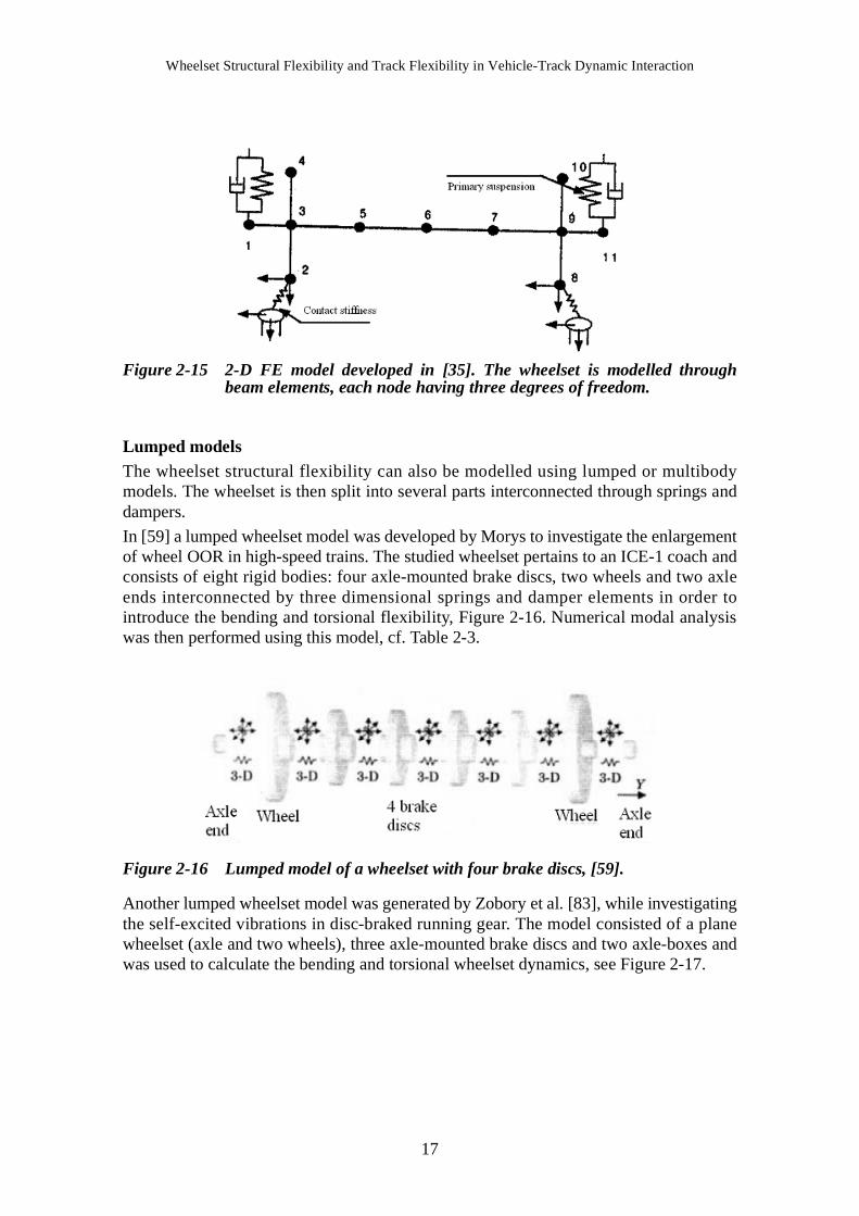
The second model, shown in Figure 2-15, was proposed by Diana et al. [35]. The modelis based on simple discretisization in which all parts of the wheelset are represented bybeam elements, each node having three degrees of freedom (dofs) being vertical andlateral displacements as well as rolling rotation. The authors mentioned that such amodel can give satisfactory representation of the axle deformation but enable only theflexural deformability of the wheels and can reproduce the wheelset behaviour up to 250Hz.
16
Wheelset Structural Flexibility and Track Flexibility in Vehicle-Track Dynamic Interaction
Figure 2-15 2-D FE model developed in [35]. The wheelset is modelled throughbeam elements, each node having three degrees of freedom.
Lumped modelsThe wheelset structural flexibility can also be modelled using lumped or multibodymodels. The wheelset is then split into several parts interconnected through springs anddampers.
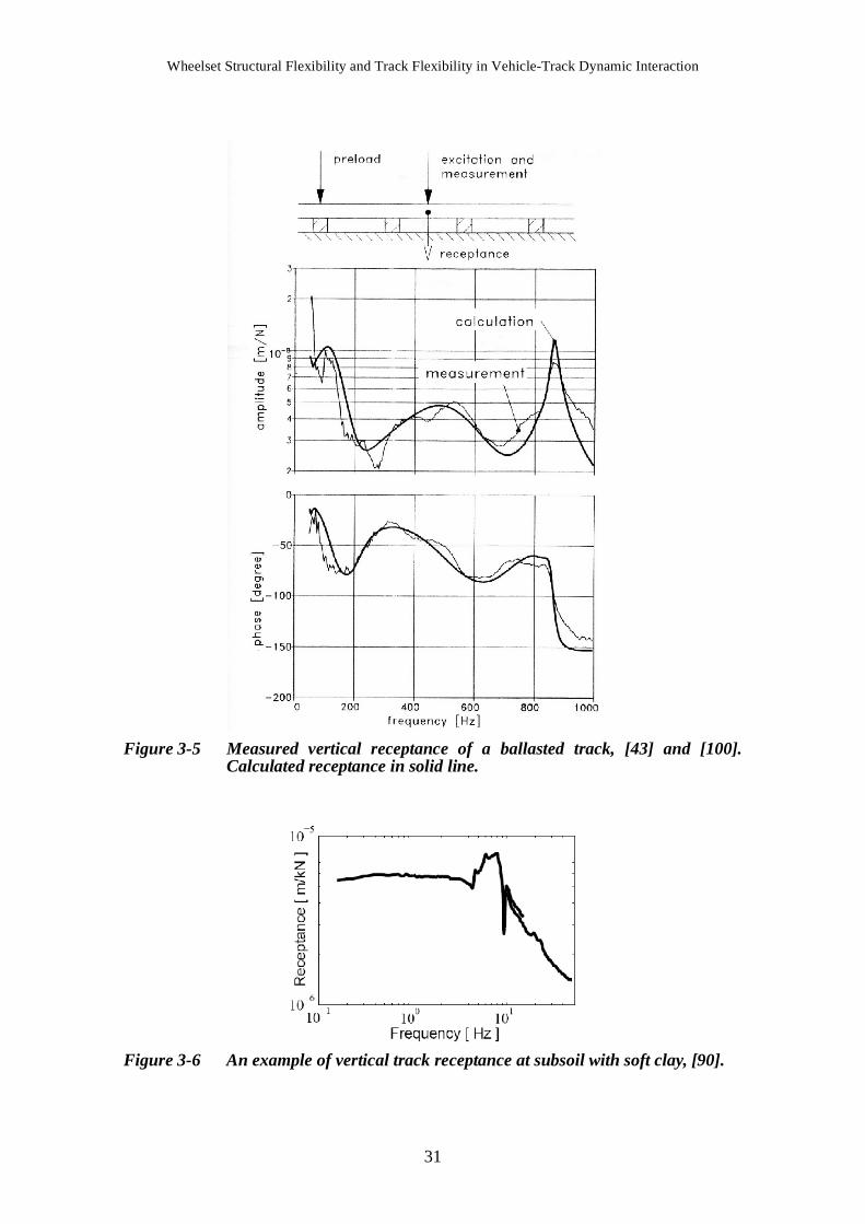
In [59] a lumped wheelset model was developed by Morys to investigate the enlargementof wheel OOR in high-speed trains. The studied wheelset pertains to an ICE-1 coach andconsists of eight rigid bodies: four axle-mounted brake discs, two wheels and two axleends interconnected by three dimensional springs and damper elements in order tointroduce the bending and torsional flexibility, Figure 2-16. Numerical modal analysiswas then performed using this model, cf. Table 2-3.
Figure 2-16 Lumped model of a wheelset with four brake discs, [59].
Another lumped wheelset model was generated by Zobory et al. [83], while investigatingthe self-excited vibrations in disc-braked running gear. The model consisted of a planewheelset (axle and two wheels), three axle-mounted brake discs and two axle-boxes andwas used to calculate the bending and torsional wheelset dynamics, see Figure 2-17.
17

Wheelset structural flexibility
Figure 2-17 Lumped model developed in [83] and used in calculating the wheelsetbending and torsion modes.
A simple lumped model, including the first wheelset torsional and bending modes, wasgenerated in [20] while investigating the lateral track forces at high-speed curving usingradial self-steering bogies, see Figure 2-18.
Figure 2-18 Lumped wheelset model including torsional and bending flexibility,[20].
Lumped wheelset models were also developed in [25], [34], [36], [42], [53], [54], and[70].
Main findings and remarksCalculated mode shapes and natural frequencies of a free wheelset: The calculated modeshapes and natural frequencies recorded from several case studies are listed in Table 2-3.The lowest torsional and bending modes recorded occurred at around 67 and 84 Hzrespectively.
18

Wheelset Structural Flexibility and Track Flexibility in Vehicle-Track Dynamic Interaction
Table 2-3 Calculated mode shapes and natural frequencies [Hz] for different types ofwheelsets.
Modelling of wheels and brake discs: Up to frequencies corresponding to the firstwheelset bending mode, the wheels and the brake discs can be modelled as rigid entities.However, wheels start to show considerable deformations at frequencies close to thesecond bending mode, [55]. Morys [59], stated that for frequencies up to 200 Hz, thewheels can be assumed as stiff and rigidly coupled to the axle. Szolc [75] noted that inthe frequency range of 0-100 Hz, the planes of the wheels and brake discs are alwaysperpendicular to the axis of the deformed wheelset which imply that the wheels can bemodelled as rigid bodies in that frequency range.
Gyroscopic effects: The influence of gyroscopic effects was examined in [55]. For aspeed of 300 km/h, the eigenfrequencies of the bending modes split up into an increasingbranch, called forward whirl, and a decreasing branch, called backward whirl. Thetorsion mode is not influenced by the rotary frequency. Similar findings were reported bySzolc, [75].
Static and dynamic imbalances: According to [57], imbalances arise from smallinaccuracies in the manufacturing process and cause a coupling between the wheelsetbending and torsional vibrations leading to creepage and wheel OOR due to continuouswear. In [55] and [56] excitations caused by dynamic and static imbalances were studied.The static imbalances were represented by mass points whereas the dynamic imbalanceswere introduced via massless rigid bodies with products of inertia.
Simplified wheelset models: A fast algorithm for modelling and investigating thewheelset flexibility was developed by Hempelmann, [43]. The wheelset axle wasmodelled as beam elements including the bending, shear and longitudinal deformationwhile the wheels were modelled as shear plate discs, see Figure 2-19. This modelcomprised only 130 dofs and showed quite good accuracy in the results according to theauthor.
Ref. Wheelset type Model First torsion
First bending
Second bending
First umbrella
Second umbrella
[38] Wheelset + axle-boxes
FE model 67 89 141 235 308
[51] Wheelset with SJ57H wheels
FE model ---- 83.9 152.5 250.5 396.9
[55] ICE wheelset, 4 axle-mounted brake discs
FE model 82.5 84.6 131.8 234.8 296.1
[59] ICE wheelset, 4 axle-mounted brake discs
Lumped, rigid wheels
95.9 82.0 182.0 ----- ------
19

Wheelset structural flexibility
Figure 2-19 An example of a simplified wheelset model developed in [43].
2.3 Influence of wheelset structural flexibility
The influence of the wheelset structural flexibility is generally examined throughnumerical simulations. This section surveys the influence of wheelset flexibility ondifferent phenomena, such as the vehicle lateral stability, track forces, wheel-out-of-roundness, wheel/rail corrugation, and wear and noise propagation.
On lateral stability
The influence of the wheelset’s bending, torsional and umbrella modes on the lateralvehicle stability was examined by Kaiser and Popp, [46], [47] by comparing the runningbehaviour of rigid respectively flexible wheelsets. The authors mentioned that thestrongest influence on the running behaviour is caused by the wheelset flexuraldisplacements. The out-of-plane bending causes a deflection of the wheelset in thevertical and lateral directions and leads to additional creepage. The influence of wheelsetflexibility on the lateral stability was also studied in [15].
On track forces and axle-box accelerations
In [16] the influence of wheelset flexibility on the longitudinal and normal track forceswas investigated through numerical simulations involving a wheelset with rigid orflexible wheelset axle. The wheelset first torsional mode was excited by means of asinusoidal corrugation on both rails with a corresponding wavelength of 0.66 m, thecorrugation being out-of-phase by 180 degrees. Hence, for a running speed of 160 km/h(44.4 m/s) the excitation frequency around 67 Hz corresponds to the wheelsetfundamental torsion mode. The authors stated that a flexible wheelset axle results inlower longitudinal force as compared to the rigid case, see Figure 2-20a, and reported arather small influence of the wheelset flexibility on the normal contact force, cf. Figure 2-20b and [17]. In addition, Andersson et al. [17] noted that the influence of the wheelsetflexibility on the vehicle lateral dynamics is believed to be stronger as a result of out-of-plane bending of the wheels.
20

Wheelset Structural Flexibility and Track Flexibility in Vehicle-Track Dynamic Interaction
Figure 2-20 Influence of the axle flexibility on the longitudinal and normal contactforces, [16].
The influence of the complexity of track and wheelset models on numerical results wasexamined in [26]. For that purpose, two track models were compared in the simulations:a so-called complete model, referring to a FE model with beam elements, and a rigidtrack model. Likewise, a FE wheelset model with 12 dofs accounting for the axlebending modes was compared to a rigid wheelset model with 5 dofs. Also, two types ofwheel-rail contact models were evaluated: A single contact and a multi-Hertzian contactmodel. The vehicle, from a Pendolino train, was simulated on a track at a speed of 170km/h. The results are summarised in Table 2-4. It can be shown that the values of thelateral axle-box accelerations and the limit cycle frequency change considerably as thecomplexity of the models decreases, leading to an over-estimation in the vehicle stabilitythreshold. The effect of wheelset flexibility on the lateral axle-box accelerations and thelimit cycle frequency can be seen by comparing the last two rows of Table 2-4. In fact thelateral acceleration in the flexible wheelset model is almost 1.7 times higher than thatreported for the rigid wheelset model.
Table 2-4 Lateral axle-box acceleration and limit cycle frequency as functions ofwheel-rail contact model, track model and wheelset model, [26].
Contact model Track model Wheelset model Lateral acceleration
(m/s2)
Limit cycle frequency (Hz)
Multiple complete 12 dofs 4.6 6.8
Single complete 12 dofs 3.26 6.7
Multiple rigid track 12 dofs 3.81 7.5
Multiple rigid track 5 dofs 2.25 8.35
21

Wheelset structural flexibility
The influence of the wheelset structural flexibility on wheel-rail forces and axle-boxaccelerations was also examined in [35], [62] and [77]. Additional studies concerning theeffects of the wheelset deformation on vehicle-track dynamics in the mid-frequencyrange were also carried out by Szolc and illustrated in [71] to [76].
On wheel out-of-roundness (OOR)
Wheel OOR or polygonalization is an imperfection on the wheel tread that can lead todetrimental influence on both tracks and wheels, result in high impact loads and cause anincrease in rolling noise, [44]. The classification of wheel imperfections and theirinfluence on the vehicle-track dynamics were reviewed in [44]. The authors alsosurveyed the possible causes of the formation and development of wheel OOR whichinclude, among other, the influence of wheelset structural flexibility.
A simple mechanism of wheel polygonalization by wear was examined by Brommundt,[25]. The author quoted that the wheelset axle torsional vibrations combined with thewheelset lateral dynamic vibrations lead to creep generation and to the formation anddevelopment of corrugation wheel wear.
The enlargement of wheelset OOR was also investigted by Morys in [59]. The authorstated that the normal force accelerates the wheel vertically causing a bending oscillationof the wheelset which in turn leads to lateral slip and material excavation. The materialexcavation due to longitudinal slip and spin plays a minor role in the OOR growth.
The growth of wheel OOR was also examined by Meywerk, [58]. The author definedtwo mechanisms behind the formation of wheel OOR. The author stated that thewheelset first and second bending modes play an important role in the formation anddevelopment of wheel OOR due to the lateral slip caused by the excitation of these twomodes.
Finally, similar findings were reported in [82].
On wheel/rail corrugation and wear
The causes, characteristics and treatments of the rail corrugation were investigated byGrassie and Kalousek in [41]. Rail corrugation is a phenomenon whereby more or lessperiodic undulations appear on the running rail surface and gives rise to large dynamicforces between wheel and rail, noise propagation and ballast deterioration, [41]. Theauthors also stated that the mechanism of corrugation formation consists of two steps:First a wavelength fixation mechanism followed by a damage mechanism. Based on thewavelength fixation mechanism, they defined six types of rail corrugations. Bootedsleepers and rutting are two types (causes) of rail corrugations where the wavelengthfixation mechanism corresponds to the wheelset flexural and torsional modesrespectively. The influence of the wheelset second torsion mode on corrugationformation was also reported by Grassie et al. [39] and by [40] while investigating theformation of corrugation on a North American transit system.
In [53] and [54], Matsumoto et al. studied the mechanism of rail corrugation formationon curved track. The authors indicated that the axle torsional stiffness has an influenceon the rail head wear index. The larger the axle torsional stiffness, the smaller the wearindex is. However, the axle torsional stiffness does not influence the wavelength ofcorrugation which is mainly influenced by the vertical system dynamics rather than bythe axle torsional oscillation.
22

Wheelset Structural Flexibility and Track Flexibility in Vehicle-Track Dynamic Interaction
The first torsional mode of a powered wheelset was introduced in [70] while studying theformation and development of rail wear. The author mentioned that the lateral vehiclemotion coupled with the wheelset first torsional mode initiate the formation of irregular,abrasive wear due to stick-slip phenomenon.
A linear wheel-track model aiming at investigating the rail corrugation at narrow curvesfor ballasted and slab tracks was developed by Tassilly and Vincent, [77]. According tothe authors the corrugation formation on the leading axle on a ballasted track issignificant in the frequency range of 60-80 Hz, at proximity of the wheelset first bendingmode, where a slight fluctuation in the vertical force can cause large transverse sliding.For the trailing axle, a longitudinal wear function is highest at around 55 Hz, which canbe related to the wheelset first, highly undamped, torsion mode. This phenomenon ismore likely to occur on narrow curves rather than on a straight track.
Similar findings and conclusions were drawn by Meinders [55] and Hempelmann et al.[43]. The latter indicated that the primary influence of the wheelset flexibility onformation of corrugation is caused by the coupling of its vertical and lateral dynamicsthrough axle bending.
On noise propagation
Thompson [78] indicated that the major source of noise from railways at high speedsoriginates from the wheel-rail region. The wheel-rail rolling noise is attributed to thestructural vibrations of the wheels and the rails excited from the contact patch area by thewheel and rail surface undulations.
Thompson and Jones reviewed in [79] the theoretical models that have been developedto predict the wheel/rail noise generation. The authors divided the wheel-rail noise intothree categories: Rolling noise which occurs on straight track and is caused by verticaldynamics induced by undulations (roughness) on the wheel and rail surfaces, impactnoise due to discontinuities at the wheel-rail level, and squealing noise which occurs atnarrow curves and is induced by lateral excitation mechanisms. The authors quoted thatnoise prediction is nowadays generally based on finite element modelling of the wheels.According to [79], the wheel natural frequencies with one-nodal circle are mostimportant in rolling noise propagation. The axial mode with zero nodal circles has apredominantly lateral motion at the wheel-rail contact point and hence it is important incurve squeal.
The propagation of squealing noise in narrow curves was investigated by Fingberg [38]and a corresponding wheel-rail model was generated. The author stated that thegeneration of squealing noise can be assigned mainly to the natural frequencies of thewheel whereas the sound radiation from the rail may be neglected. Likewise, [69]indicated that squealing noise in narrow curves is related to the bending vibration of thewheel discs excited by the stick-slip in the wheel-rail contact.
In [67], Remington reviewed and presented the current state of knowledge of wheel-railrolling noise. The author stated that the sound radiation can be caused by a variety offactors such as vertical and horizontal rail vibrations, axial and radial wheel treadvibrations, etc. He further indicated that in the frequency range of 315-630 Hz all theabove mentioned factors contribute to sound radiation. From 800 to 2500 Hz, the soundradiation due to vertical rail vibration dominates, whereas above 2500 Hz soundradiation originating from the radial wheel vibrations tends to dominate.
23

Wheelset structural flexibility
Finally, in the state-of-the-art survey presented by Vincent, [81], a series of actions wereproposed in order to reduce and control the rolling noise at the source. These actionsinclude, among others, wheel damping, i.e. installation of damping material on the wheelto control the wheel noise, resilient wheels and shielding of the wheel sides by means ofdamped steel plates.
Table 2-5 presents a list of wheelset structural flexibility (and track flexibility) models.Aim of the study, frequency range of interest and modelling methods are also specified.
Table 2-5 Review of structural flexibility models for wheelsets.
Ref.Aim of the study, frequency range
Wheelset model Track model
[16] Vehicle-track dynamic interaction, up to 1000 Hz
Axle: Beam elements, incl. bending and torsionRigid wheels
Beam on discrete supports
[17] [18]
Vehicle-track dynamic interaction
Axle: Beam elementsWheel: 10-noded quadratic tetrahedron elementsCraig-Bampton reduction, [6]
Beam on discrete supports, non-linear pad and ballast properties
[20] Lateral track forces at high-speed curving
Lumped wheelset model: First torsion mode onlyRigid wheels
Moving track model Lateral track stiffness included
[21] Development of a new generation of high performance wheelsets
Axle: Timoshenko beam elementsWheel: Solid brick elements
not specified
[25] Polygonalization of wheels by wear
Lumped wheelset model: First torsion mode onlyRigid wheels
not specified
[34] Interaction between track superstructures and vehicles
Lumped wheelset model:Torsion mode only
Beam on discrete supports
[35] Vehicle-track dynamic interaction at high speeds
Two-dimensional FE model, modelled by beam elements
Beam on discrete supports
[38] Model of wheel-rail squeal noise at curving
Axle: Timoshenko beam elementsWheel: Annular shell elements
Beam on discrete supports
[39][40]
Rail corrugation mitigation for transit traffic
Lumped wheelset model: Torsional modes onlyRigid wheels
Beam on discrete supports
[42] Improve the design of a locomotive bogie,0-100 Hz
Axle: Lumped model, incl. first torsion and bending modesRigid wheels
not specified
[43] Modelling of wheelset-track dynamic interaction,0-3500 Hz
Axle: Beam elements, incl. bending, torsion and elongationWheel: Plate elements
Beam on discrete supports
24

Wheelset Structural Flexibility and Track Flexibility in Vehicle-Track Dynamic Interaction
[46][47][28]
Interaction between elastic wheelset and elastic rails
FE model, solid elements Beam on discrete supportsMoving track model, two dofs
[51] Identification of a finite element wheelset model
Axle: Beam and solid elementsWheels: Brick elements
not specified
[53] [54]
Rail corrugation on curved track
Lumped wheelset model: First torsion mode onlyRigid wheels
not specified
[55][56]
Modelling of wheelset as a rotating elastic system and irregular wear
FE modelAxle: Solid elementsWheels: Solid elements
not specified
[57] Wheel tread OOR by static & dynamic imbalances
Axle: Elastic beam elementsRigid wheels & brake discs
not specified
[58] Polygonalization of railway wheels
Continuous modelAxle: 1-D Timoshenko beamWheel: 2-D Kirchoff’s plate
1-D beam element
[59] Enlargement of wheel OOR on high-speed trains,0-300 Hz
Axle: Lumped model incl. torsion and bendingRigid wheels and brake discs
Beam on discrete supports
[60] Prediction of short-pitch corrugation
Axle: Timoshenko beam, Wheel: Rotational symmetric shells
Beam on discrete supports
[62] Short-pitch wheel-rail corrugation
FE model followed by Craig-Bampton reduction
Beam on discrete supports
[68] Simulation of high-frequency vehicle-track interaction
Finite element model Beam on discrete supports including ballast mass
[69] Noise propagation due to wheel-rail contact forces
Wheel: FE model, ring elements based on Mindlin’s plate theory
not specified
[70] Study of wheel-rail corrugation with flexible wheelsets
Axle: Lumped model incl. first torsionRigid wheels & brake discs
Beam on discrete supports
[71] to [76]
Vehicle-track interaction in the mid-frequency range
Continuous-discrete wheelset axleRigid wheels and brake discs
Beam on discrete supports
[80] Wheel-rail forces at high frequencies
FE model not specified
[83] Vibrations in disc-braked running gear
Lumped wheelset model incl. bending and torsionRigid wheels
not specified
Ref.Aim of the study, frequency range
Wheelset model Track model
25

Wheelset structural flexibility
Also, the structural flexibility of wheelsets was considered in the following studies:
In [22] while studying the influence of plastic deformation of corrugated rails.
In [23] while investigating the performance of wide-band dampers in wheels and theirefficiency in reducing wheel/rail wear and cutting noise propagation.
In [24] while assessing the dynamic stiffness properties of bogie components, includingwheelsets, on the design of high axle-load bogies.
In [44] while reviewing the mechanisms of irregular wear on wheel and rail surfaces.
In [50] while studying a wheelset eigenmodes and natural frequencies under gyroscopiceffects.
In [52] while designing and developing a new freight wheelset for 30 tonne axle loads.
In [82] while examining the formation of wheel OOR due to unhomogeneous wear of thewheel treads.
In [83] while studying the self-excited vibrations in disc-braked running gears and inbrake-pad suspension system.
The wheel structural flexibility was considered in the following investigations:
In [29] while designing and analysing a new method to reduce and cut the noise radiationfrom wheels via visco-elastic layers, and in [37], [48], [69], and [78].
26

Wheelset Structural Flexibility and Track Flexibility in Vehicle-Track Dynamic Interaction
3 Track flexibility
Track flexibility has for a long time been regarded as an interesting parameter forcondition assessment and monitoring of the track, [87]. Tracks are seldomly laid onhomogeneous subgrades. As a result, the track stiffness varies along the track and thisvariation is experienced by the train and the track, [90]. Furthermore, the properties ofthe track components, such as rails, rail pads, fastenings, etc., may also differ andcontribute to the track flexibility variation and lead to fluctuations in track forces andnoise propagation, [96].
This chapter briefly describes measurements methods and results of track flexibility aswell as modelling methods of track flexibility. It also reviews the influence of thisflexibility on vehicle-track dynamic interaction.
3.1 Measurements of track flexibility
Standstill techniquesAs implied by the name, the standstill techniques measure track flexibility without anymoving vehicle at one track section at a time, which makes them time consuming andexpensive. As mentioned by Berggren [87], a simple way of measuring the track stiffnesscan be achieved by attaching a displacement transducer at a certain track section andmeasuring the response due to a train passage. The stiffness can be derived if the staticaxle load is known.
Impact hammer is another way of measuring track stiffness. Here the impact hammer isequipped with a force transducer while an accelerometer is attached to the rail head or ata sleeper. Measurements are taken from several hits with the hammer on the rail and thetransfer function between the impulse force of the hammer and the acceleration at the railis obtained. This method is suitable for problems associated with high frequencies, aboveat least 200 Hz, such as noise and vibrations, [87].
Falling Weight Deflectometer (FWD) is a fast method and can cover shorter distances oftrack according to [87].
Track Loading Vehicle (TLV) can apply a static, vertical preload on the track throughhydraulic jacks to measure track stiffness. Usually the rail heads are loaded but there isalso a possibility to preload a sleeper. A typical example of such a vehicle is Banverket’sTrack Loading Vehicle illustrated in Figure 3-1, see also [86] and [87].
The TLV shown in the figure below is equipped with three hydraulics shakers, twoacting vertically and one laterally and is capable of measuring the lateral and verticaltrack flexibilities in the frequency range of 1-200 Hz. The response is measured throughaccelerometers placed on the rail heads or on the sleeper.
27

Track flexibility
Figure 3-1 Example of track loading vehicle capable of measuring the vertical andlateral track flexibility in the frequency range of 1-200 Hz, [89].
Rolling stiffness techniquesIn rolling stiffness measurements the vertical track stiffness is usually assessedcontinuously while the vehicle is rolling. These methods can provide information on thevertical track stiffness over longer distances within relatively shorter time as comparedto the standstill approaches.
An example of a rolling stiffness measurement vehicle is illustrated in Figure 3-2. Thevehicle, developed by the Swedish National Rail Administration (Banverket), is a rebuilttwo-axle freight wagon equipped with two 4000 kg vibrating masses above one of theaxles and is capable of measuring the vertical track stiffness continuously over long tracksections in the frequency ranges of 5-50 Hz via forces and accelerations recorded at theaxle-boxes. The vertical motion of the masses is generated and monitored by means oftwo hydraulic cylinders. The imposed static axle load is about 180 kN. Additionalinformation regarding this vehicle can be found in [88]. Additional examples of rollingstiffness vehicles were reviewed by Berggren in [87]. An example of a rolling stiffnessvehicle is also illustrated in [85].
Figure 3-2 Example of rolling stiffness vehicle capable of measuring vertical trackflexibility continuously along the track for frequency range of 5-50 Hz,[88].
28

Wheelset Structural Flexibility and Track Flexibility in Vehicle-Track Dynamic Interaction
Results and findings
Vertical and lateral track dynamics
According to Dahlberg [91], several well damped resonances can be found in a trackstructure. Sometimes, when the track is built on soft subgrade, a vertical resonance maytypically appear in the frequency range of 20-40 Hz. This resonance occurs when thetrack and a great deal of the track substructure vibrates on a layered structure of theground. A second track resonance usually occurs in the frequency range of 50-300 Hzwhere the track superstructure (rails and sleepers) vibrates vertically on the ballast bed.The rails and the sleepers provide the “mass” and the ballast provides the “spring” forthis resonance vibration. The ballast also provides a large amount of damping, so thisresonance is very well damped. A third resonance can often be found in the frequencyrange of 200- 600 Hz where the rail is bouncing on the rail pads. The rail pad acts as aspring inserted between the rail and the sleeper. Also here, the ballast provides most ofthe damping. Another resonance frequency referred to as pinned-pinned frequencyoccurs at around 1000 Hz. The corresponding peak is narrow, indicating that theresonance at this frequency is very lightly damped. The pinned-pinned frequency occurswhen the wavelength of the bending waves of the rail is twice the sleeper spacing. In thiscase the bending vibration of the rail has nodes at the supports, i.e. at the sleepers. SeeFigure 3-3a-c.
The resonances in the lateral direction often occur at frequencies around 50, 150, 550and 1500 Hz according to [89]. At around 50 Hz, the rail and the support move in phase,while at 150 Hz they move out-of-phase. At around 550 Hz, the lateral pinned-pinnedmode takes place and finally, close to 1500 Hz, the rail head and rail foot vibrate out-of-phase, cf. Figure 3-3d-f. The latter mode is not shown in Figure 3-3.
Figure 3-3 Vertical and lateral track resonances in the frequency range of 0-1000Hz based on [43] and [100].
29

Track flexibility
Examples of track flexibility measurement results
This section describes and illustrates some examples of track flexibility measurementsand corresponding results. In [40] the vertical and lateral receptances were assessed bymounting accelerometers on the rail head and hitting it with an instrumented hammer.Parts of the results are illustrated in Figure 3-4. The measured vertical receptancemagnitude displays a drop in the frequency range of 0-60 Hz and a peak at around 200Hz.
Figure 3-4 Measured vertical receptance obtained in [40]. Calculated receptance insolid line.
Figure 3-5 illustrates a measured vertical receptance of a ballasted track, [43] and [100].In the measurements, the track has been preloaded by a vehicle whose closest wheel is atthe distance shown in Figure 3-5. The results show a decrease in the track receptance inthe frequency range of 0-80 Hz and three peaks at around 100, 500 and 870 Hzrespectively. According to [100], in the first resonance the superstructure vibrates on theballast while in the second resonance the rails and sleepers vibrate on the rail pads andthe third resonance corresponds to the vertical pinned-pinned mode.
An example of measured vertical track receptance for a subsoil of soft clay and a staticpreload of 90 kN per rail is shown in Figure 3-6, [87]. The measurements wereperformed using the TLV shown in Figure 3-1. Berggren et al. [86], stated that for thisparticular case, a resonance occurs at only 5-8 Hz due to the soft soil and is followed byan anti-resonance at 9 Hz whereas the track is stiffer for higher frequencies.
Finally, Figure 3-7 illustrates measured vertical track stiffness obtained using the rollingstiffness vehicle shown in Figure 3-2, at a speed of 20 km/h [90]. The results display acontinuous change in the vertical track stiffness along the three-kilometre section. Theyalso show large variations in the vertical stiffness when passing over a bridge.
30
Wheelset Structural Flexibility and Track Flexibility in Vehicle-Track Dynamic Interaction
Figure 3-5 Measured vertical receptance of a ballasted track, [43] and [100].Calculated receptance in solid line.
Figure 3-6 An example of vertical track receptance at subsoil with soft clay, [90].
31

Track flexibility
Figure 3-7 Vertical track stiffness obtained using the rolling stiffness technique,[90].
Table 3-1 lists several cases where the vertical and lateral receptances were measuredusing the standstill or rolling stiffness techniques.
Table 3-1 Example of studies where the track receptances were measured using thestandstill or rolling stiffness techniques.
Ref General aim of the studyMeasurement technique
Excitation,quantity of interest
[40] Rail corrugation mitigation for transit traffic
Standstill Hammer excitationsVertical and lateral track stiffnesses
[43] Modelling of the vehicle-track dynamic interaction
Standstill Hammer excitationsVertical and lateral track stiffnesses
[76] Bogie-track dynamic interaction in the mid-frequency range
Standstill Vertical and lateral track stiffnesses
[77] Linear vehicle-track model for rail corrugation
Standstill Stepped-sine excitationsVertical and lateral track stiffnesses, f = 1-1000 Hz
[80] Measurements and simulations of track forces at high frequencies
Standstill Hammer excitationsVertical track stiffness
[84] Modelling and simulation of train-track interaction
Standstill Stepped-sine and hammer excitationsVertical and lateral track stiffnesses
[88] Simulation, development and field testing of a track stiffness vehicle
Rolling stiffness
Vertical track stiffness
[89] Modelling of track flexibility for rail vehicle dynamics simulations
Standstill Stepped-sine excitationsVertical and lateral stiffnesses, f = 1-200 Hz
[92] Vehicle-track dynamic interaction Standstill Stepped-sine and hammer excitationsVertical stiffness, f = 1-1000 Hz
[94] Determination of track properties Standstill Hammer excitationsVertical track stiffness
32

Wheelset Structural Flexibility and Track Flexibility in Vehicle-Track Dynamic Interaction
3.2 Modelling of track flexibility
Continuous track modelsContinuous track flexibility models were reviewed in Popp et al. [66], which classifiedthe track models into continuum track models for moving loads problems and finiteelement models. Knothe and Grassie [100], also presented a hierarchy of track flexibilitymodels based on the track component modelling.
Dahlberg [91] listed four types of continuous track models: Beam (rail) on continuouselastic foundation, beam (rail) on discrete supports, beam (rail) on discrete supportsincluding ballast model, beams (rails) on sleepers embedded in continuum and including3-D FE models. Track flexibility models reviewed below utilize this classification.
Beam on continuous elastic foundation
In these models, the rail is represented by a beam resting on a continuous elasticfoundation which is modelled by an evenly distributed linear spring stiffness, Figure 3-8.This kind of track model, first introduced by Winkler, is rather simple and is used forfast-time simulations. The model shown in Figure 3-8 is only useful for static loading ofa track since the dynamic track properties (mass, damping) are not included [91].
Figure 3-8 Continuous track model on elastic foundation. The wheel static load isrepresented by the load P. The dashed line refers to the beam deflectionunder loading, [91].
Beam on discrete supports
This type of continuous track models allows for better representation of the trackdynamic behaviour. Usually, the rail is modelled as a continuous beam and connected toa rigid mass (sleeper) via springs and dampers in parallel (fastenings and rail pads). Thesleeper in turn is resting on elastic foundation representing the ballast and subballaststiffness, [91]. This type of track models has been widely in many studies, see also Table2-5. An example of a track modelled as continuous beam on discrete supports is shownin Figure 3-9.
Figure 3-9 Example of a continuous track model on discrete supports, [40].
33

Track flexibility
Beam on discrete supports including ballast mass
For this type of track model, a new rigid mass representing the ballast is introduced. Atypical track model is shown in Figure 3-10. Each rigid mass representing the ballast isconnected to the subgrade through a spring and damper in parallel. Also, a deflection atone sleeper will influence the displacement at adjacent ones through cross-couplingmodel elements.
Figure 3-10 Example of continuous track model on discrete supports includingballast mass, [68].
Beam on sleepers embedded in continuum, including 3-D FE model
According to [91], these models present the most realistic track modelling but requireslarge computer capacity. The rails and sleepers are modelled as beams connected throughsprings and dampers. The sleepers are embedded in a continuous medium which requiresthe track bed to be modelled by three-dimensional finite elements, see Figure 3-11.
Figure 3-11 Example of continuous track model embedded in continuum, [91].
Moving track modelsThe track and its pertinent flexibility can also be modelled through so-called movingtrack models. In contrast to the common continuous track models above, moving trackmodels are less complicated, have limited number of degrees of freedom and hence areless time consuming and can be used for long-distance simulations. Depending on thecomplexity level, such models can be appropriate for investigating the vehicle-trackinteraction for frequencies up to 200 Hz. Vertical static preload effects can also beaccounted for in these models as well as the sleeper passing effect. Moving track modelsare situated under each wheelset and follow the vehicle with the same speed.
34

Wheelset Structural Flexibility and Track Flexibility in Vehicle-Track Dynamic Interaction
The concept of moving track model has been adopted in multibody dynamic softwaressuch as GENSYS [95], SIMPACK [97] and VAMPIRE [93], and has also been used inseveral studies such as [11], [20], [47], [98] and [99]. A series of moving track modelswith different levels of complexity was also developed and examined by Claesson [89].Some examples of moving track models are illustrated in Figure 3-12.
The track model shown in Figure 3-12a has one degree of freedom (dof) in the lateraldirection, while the track models illustrated in Figure 3-12b-c have one vertical and onelateral dof. The moving track model in Figure 3-12d has two levels of vertical stiffnessand one level of lateral stiffness (4 dofs) and finally the two remaining models have onelevel of vertical stiffness and two levels of lateral stiffness (5 dofs).
Figure 3-12 Examples of moving track models from: (a) Andersson et al. [20], (b)SIMPACK [97], (c) Kaiser and Popp [46], (d) Iwnicki et al. [99], (e)GENSYS [95] and (f) Iwnicki [98].
3.3 Influence of track flexibility
The influence of track flexibility on vehicle-track dynamic interaction has beenexamined in different contexts. This section focuses on the effects of this flexibility ontrack forces and rail corrugation. The influence of track dynamics on noise propagationhas been reviewed in Section 2.3.
On track forces
35

Track flexibility
Ripke and Knothe [68] have compared simulated vertical contact forces at the leadingwheels of an ICE coach at 250 km/h, using rigid and flexible models respectively. In theformer model a rigid track and a rigid wheelset are considered, while in the latter theelastic properties of the track and wheelset were included. Figure 3-13 shows two-secondtime histories, corresponding to 140 m. The flexible model, referred to as SiRaGe model,provides the P2 resonance frequency of track and vehicle at around 66 Hz and the sleeperpassing frequency at around 117 Hz (sleeper distance is 0.6 m) while the rigid model,referred to as MEDYNA model, lacked such information and covered only lowfrequency peaks corresponding to the vehicle rigid body motions. The influence of trackmodelling on simulations results was also investigated by Bruni et al. [26], see Table 2-4.
Figure 3-13 Vertical contact force histories of the leading wheels (top) andcorresponding Fourier spectrum (bottom) obtained using rigid (left)respectively flexible (right) wheelset-track model, [68].
In addition, the influence of track dynamics on wheel-rail forces was investigated by:Morys [59], Szolc [73] and [76], Diana et al. [34] and [35].
On rail corrugation
The influence of the P2 resonance on the formation and development of several types ofrail corrugation was discussed in [41]. The possible sources of rail corrugation, includingthe effects of track dynamics, were also examined in [91].
36

Wheelset Structural Flexibility and Track Flexibility in Vehicle-Track Dynamic Interaction
4 The present work
4.1 Introduction
In Chapter 2 and 3 the present knowledge in the research field at hand was reviewed.Despite that several studies have examined the effects of wheelset structural flexibilityand track flexibility, several questions still have to be answered, for instance:
• What are the main effects of the wheelset structural flexibility on the wheel-rail forcesin the frequency range of 0-200 Hz?
• How do the track dynamic properties influence the wheel-rail forces in this frequencyrange?
• How does the choice of track model and pertinent data affect the outcome of thesimulations and what type of track model is most suitable?
• What is the influence of the track irregularities corresponding to a frequency range of0-200 Hz and how to achieve a proper representation of these irregularities?
Paper A focuses on the experimental and numerical modal analyses of a locomotivewheelset.
In Paper B, the influence of the wheelset structural flexibility on wheel-rail forces in thefrequency range of 0-100 Hz is investigated for the locomotive in Paper A. Results fromsimulated track forces are compared to measured ones.
In Paper C the influence of track flexibility on the wheel-rail forces in the frequencyrange of 0-150 Hz is assessed through simulations and measurements. Track flexibilitymeasurements are now utilized in the locomotive case study. Moving track models aredeveloped and used to model the track flexibility.
Paper D features a new case study, involving a newly designed high-speed train runningon two adjacent tracks with different track components. Simulated track forces arevalidated against corresponding measurements in the frequency range of 0-200 Hz.
4.2 Summary of Paper A
In Paper A [31], a wheelset pertaining to a Swedish locomotive is selected and itsdynamic properties in the frequency range of 0-500 Hz are investigated throughexperimental modal analysis (EMA) assuming free boundary conditions. The wheelsetunder consideration has been instrumented and used during on-track measurements. Ithas a wheel diameter of 1.3 m and its total mass amounts to 2960 kg. The wheelsetshows relatively low fundamental eigenfrequencies: the first bending mode occurs atonly 55 Hz and the second bending mode is at 82 Hz. The first and second umbrellamodes, where the wheels deform in an umbrella-like shape, occur at 121 and 163 Hzrespectively. The damping ratio for the first five eigenmodes is the less than 1%.
A detailed finite element (FE) model, including the gear-box and its components, is thendeveloped and validated against the measurements for frequencies up to 200 Hz, cf.Figure 4-1. Results obtained from the FE model showed good agreement with themeasurements. A parametric study revealed that for the present wheelset, not only theaxle flexibility but also the wheels’ flexibility plays an important role in the dynamics of
37

The present work
the wheelset at frequencies below 100 Hz. In the numerical analysis, the gear-box isattached to the axle via linear springs in the longitudinal, lateral and vertical directions.The presence of the 680 kg gear-box and its components does not essentially influencethe wheelset flexible modes for frequencies up to about 200 Hz. However, the presenceof the gear-box does influence the wheelset rigid body properties.
Torsional excitation was not performed in the EMA. However, the torsional modes ofthe wheelset are calculated using a model comprising the two wheels and the axle gearwheel rigidly attached to the wheel axle. The first torsional mode occurs at only 47 Hz.
Figure 4-1 Five fundamental eigenmodes and eigenfrequencies derived from thefinite element model in [31].
4.3 Summary of Paper B
In Paper B [32], the influence of the locomotive’s wheelset structural flexibility on thevehicle-track dynamic interaction is investigated in the frequency range of 0-100 Hzthrough simulations and measurements.
In the numerical simulations the wheelset structural flexibility is introduced viaeigenmodes derived from the FE model in Paper A and displayed in Figure 4-1. Thestructural flexibility is considered for the wheelsets of the leading two-axle bogie and thegear-box is modelled as a separate and rigid entity attached to the wheelset in thelongitudinal, lateral and vertical directions and to the bogie frame in the vertical directionthrough linear stiff springs and viscous damping. In contrast, the wheelsets of the trailingbogie are modelled as rigid bodies and the gear-box mass is distributed between thewheelset and the bogie frame.
A 780 m long tangent track section located near the Swedish city of Sala is selected forextensive on-track measurements. Along this section a constant test speed of 140 km/h is
38

Wheelset Structural Flexibility and Track Flexibility in Vehicle-Track Dynamic Interaction
essentially recorded. The track components consist of Swedish BV 50 rails mounted onconcrete sleepers through Hambo fasteners. Plastic rail pads, of 5 mm in thickness, areplaced between the rails and the sleepers. The sleeper distance is nominally 0.65 m.
Measured track misalignments are introduced in the simulations. The wavelengthinterval considered in this study is λ = 0.5-100 m. The track flexibility is represented bya moving track model consisting of five degrees of freedom, see Figure 4-2, and the trackflexibility data are derived from previous experience in this field. The sleeper passingeffect is considered by varying the track stiffness when the wheelset is passing betweenany two sleepers.
Simulated results showed fairly good agreement with the measured track forces. It wasshown that the lateral track forces are more influenced by the wheelset structuralflexibility than the vertical ones. From parametric studies it is concluded that themagnitude of the vertical track forces increases as the stiffness of the track is increased.Sleeper passage, short wavelength irregularities and increasing running speed alsoamplify the vertical track forces.
Figure 4-2 Five degree of freedom moving track model used in [32]. (This model iscalled Model A in Paper C and D).
4.4 Summary of Paper C
Paper C [33] studies the effects of the track flexibility on the wheel-rail forces in thefrequency range of 0-150 Hz for the locomotive case study above. For that purpose trackflexibility measurements are carried out for a track section, at a sleeper, along the presenttangent track.
In this way the vertical and lateral receptances, in the frequency range of 0-200, aremeasured using Banverket’s track loading vehicle (TLV). In order to study the influenceof static preloads and dynamic amplitude on the track dynamics, two vertical preloads of50 and 90 kN per rail and two different amplitudes are applied.
Measured track irregularity and vertical track roughness, sampled for each 0.25 mrespectively 0.01 m, are introduced in the simulations. The wavelength intervalconsidered in this study is 0.25-100 m. Hence, at a speed of 140 km/h, the maximumexcitation frequency is about 150 Hz.
39

The present work
For a better representation of the track flexibility three moving track models, whichdiffer in terms of complexity and number of dofs, are developed and tested. Trackflexibility data are then extracted for each model based on the measured receptancesabove.
Simulated wheel-rail forces are again compared to measured forces sampled at 600 Hzobtained from on-track measurements performed by Interfleet Technology.
This paper reveals that the track flexibility influences the frequency content of thewheel-rail forces significantly. It also highlights the importance of reliable track inputdata and pertinent track modelling when simulating and investigating different aspects ofthe vehicle-track dynamic interaction. Track roughness contributes to the higherfrequency content of the vertical track force and its inclusion in the simulations isimportant when predicting various damage mechanisms. The wheelset structuralflexibility influences the lateral force significantly whereas its effect on the vertical forceis small for this case study.
Figure 4-3a shows the measured and simulated power spectral density of the verticalforce of the left leading wheel. In the simulations track Model A shown in Figure 4-2 isused.
The introduction of the “new data” (dark grey line) in Paper C has led to a majorimprovement in simulated results for virtually the whole frequency range studied ascompared to the “old data” (light grey line) of Paper B. The influence of the choice oftrack flexibility model is illustrated in Figure 4-3b. The simulated vertical force obtainedfrom a more advanced track model shows even better agreement with the measurements,especially for frequencies above 100 Hz.
Figure 4-3 Measured and simulated power spectral density of the vertical wheel-rail force of the left leading wheel: (a) using data from [32] and newdata extracted from measurements together with track Model A, (b)using data from measurements and track Model C, [33].
40

Wheelset Structural Flexibility and Track Flexibility in Vehicle-Track Dynamic Interaction
4.5 Summary of Paper D
In Paper D a new case study involving a motor coach running on two adjacent trackswith different track components is examined for speeds up to 280 km/h.
Two two-kilometre long tangent track sections, referred to as “down-track” and “up-track”, are selected and investigated. Along these tracks, located near the Swedishvillage of Väring between Skövde and Töreboda, a high and essentially constant speedwas recorded.
With respect to track components, the down-track is regarded as a modern track. Therails have a UIC 60 profile with an inclination 1:30 and are mounted on concrete sleepersthrough Pandrol fastenings. Rubber rail pads of 10 mm in thickness are placed betweenthe rails and the sleepers. On the other hand, the up-track has Swedish BV 50 rails withan inclination 1:30 mounted on shorter concrete sleepers through Fist fasteners. Rubberrail pads of 5 mm in thickness are used. The sleeper distance is nominally 0.65 m forboth tracks.
Rolling stiffness measurements, where the vertical track stiffness is measuredcontinuously while a test vehicle is rolling, are carried out using Banverket’s rollingstiffness measurement vehicle (RSMV). The vehicle was used to measure the verticaltrack stiffness over the entire two two-kilometres track sections in the frequency range of5-50 Hz. In contrast, the TLV was used to measure the lateral and vertical trackdynamics at three discrete and parallel sections along the two two-km track sections forthe frequency range of 1-200 Hz. The selected sections for the standstill measurementsinclude, at each track, two sections at two adjacent sleepers and one section between thetwo sleepers. In order to study the influence of preloads on the track dynamics twovertical static preloads of 50 and 75 kN per rail are selected, the latter essentiallycorresponding to the present vehicle wheel load. Among other things, the resultsobtained from the track flexibility measurements show that the up-track is both staticallyand dynamically stiffer as compared to the down-track, see Figure 4-4.
Figure 4-4 Magnitude of vertical track receptance at 75 kN preload per rail for thethree sections investigated (a) Down-track, (b) Up-track.
41

The present work
The track flexibility was introduced through the moving track models developed inPaper C. The speeds of interest are here essentially 220 and 275 km/h. For these speeds itis possible to compare the vehicle dynamics at both tracks and also investigate theinfluence of track flexibility and speed on the track forces.
Measured track irregularities and vertical track roughness are also introduced. Thewavelength interval considered in this paper is 0.25-100 m. Hence at a running speed of220 km/h, corresponding to the lowest speed considered, the maximum verticalexcitation frequency is about 244 Hz.
From the track force measurements it can be concluded that the up-track vertical forcesare significantly higher than those of the down-track, the track overall stiffness andsleeper passing effect being two explanations to this. With low-pass filtering at 20 Hz,like in UIC 518, the down- and up-track RMS-values of the vertical dynamic force isreduced to less than a half respectively a fifth.
Parametric studies confirm a significant influence of the track flexibility on the trackforces for frequencies above 80 Hz, whereas the track irregularity difference of the twotracks mainly influences the vertical track force at frequencies around 50 Hz. Thewheelset structural flexibility shows an influence on the lateral track force at the stifferup-track, whereas its effect on the vertical force is rather small. The parametric studiesalso reveal that modifications of the vertical track receptance, motivated by uncertaintiesin the measurements, can improve the simulated forces, in particular the PSDs.
42
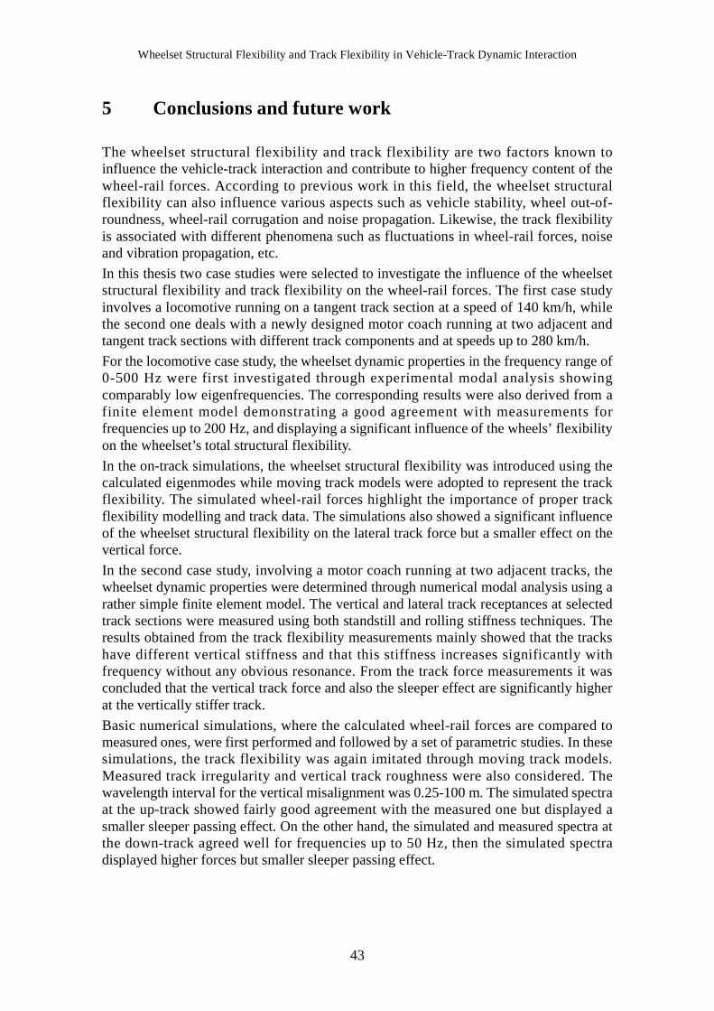
Wheelset Structural Flexibility and Track Flexibility in Vehicle-Track Dynamic Interaction
5 Conclusions and future work
The wheelset structural flexibility and track flexibility are two factors known toinfluence the vehicle-track interaction and contribute to higher frequency content of thewheel-rail forces. According to previous work in this field, the wheelset structuralflexibility can also influence various aspects such as vehicle stability, wheel out-of-roundness, wheel-rail corrugation and noise propagation. Likewise, the track flexibilityis associated with different phenomena such as fluctuations in wheel-rail forces, noiseand vibration propagation, etc.
In this thesis two case studies were selected to investigate the influence of the wheelsetstructural flexibility and track flexibility on the wheel-rail forces. The first case studyinvolves a locomotive running on a tangent track section at a speed of 140 km/h, whilethe second one deals with a newly designed motor coach running at two adjacent andtangent track sections with different track components and at speeds up to 280 km/h.
For the locomotive case study, the wheelset dynamic properties in the frequency range of0-500 Hz were first investigated through experimental modal analysis showingcomparably low eigenfrequencies. The corresponding results were also derived from afinite element model demonstrating a good agreement with measurements forfrequencies up to 200 Hz, and displaying a significant influence of the wheels’ flexibilityon the wheelset’s total structural flexibility.
In the on-track simulations, the wheelset structural flexibility was introduced using thecalculated eigenmodes while moving track models were adopted to represent the trackflexibility. The simulated wheel-rail forces highlight the importance of proper trackflexibility modelling and track data. The simulations also showed a significant influenceof the wheelset structural flexibility on the lateral track force but a smaller effect on thevertical force.
In the second case study, involving a motor coach running at two adjacent tracks, thewheelset dynamic properties were determined through numerical modal analysis using arather simple finite element model. The vertical and lateral track receptances at selectedtrack sections were measured using both standstill and rolling stiffness techniques. Theresults obtained from the track flexibility measurements mainly showed that the trackshave different vertical stiffness and that this stiffness increases significantly withfrequency without any obvious resonance. From the track force measurements it wasconcluded that the vertical track force and also the sleeper effect are significantly higherat the vertically stiffer track.
Basic numerical simulations, where the calculated wheel-rail forces are compared tomeasured ones, were first performed and followed by a set of parametric studies. In thesesimulations, the track flexibility was again imitated through moving track models.Measured track irregularity and vertical track roughness were also considered. Thewavelength interval for the vertical misalignment was 0.25-100 m. The simulated spectraat the up-track showed fairly good agreement with the measured one but displayed asmaller sleeper passing effect. On the other hand, the simulated and measured spectra atthe down-track agreed well for frequencies up to 50 Hz, then the simulated spectradisplayed higher forces but smaller sleeper passing effect.
43

Conclusions and future work
The parametric studies showed that modifications imposed on the measured verticalreceptance can significantly improve the simulated forces and lead to a good agreementover the entire frequency range. The studies also confirmed a significant influence of thetrack flexibility on the track forces for frequencies above 80 Hz, whereas the trackirregularity difference between the two tracks mainly influenced the vertical track forceat frequencies around 50 Hz. The wheelset structural flexibility showed an influence onthe lateral force especially at the stiffer up-track, whereas its effect on the vertical forceis rather small.
This thesis shows that lateral and vertical wheel-rail forces can be predicted bymultibody dynamic simulations up to frequencies of at least the sleeper passingfrequency. However, measurements of especially track flexibility plus trackirregularities and roughness are important to the success of such simulations. Properrepresentation of wheelset structural flexibility is also important in predicting lateralwheel-rail forces. Further revisions of UIC 518 and EN 14363 should consider thepotential of saving time and cost by using vehicle-track simulations. Also today’s upperfrequency limit of 20 Hz for the wheel-rail forces in these codes should be raised toaccount for wheel and rail fatigue damage.
Further work should assess the influence of the wheelset and track flexibilities on wheel-rail forces at curve negotiation. Vehicle lateral stability should also be studied withrespect to the flexibilities mentioned.
44
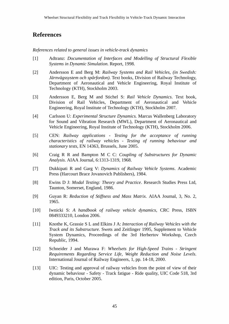
Wheelset Structural Flexibility and Track Flexibility in Vehicle-Track Dynamic Interaction
References
References related to general issues in vehicle-track dynamics
[1] Adtranz: Documentation of Interfaces and Modelling of Structural FlexibleSystems in Dynamic Simulation. Report, 1998.
[2] Andersson E and Berg M: Railway Systems and Rail Vehicles, (in Swedish:Järnvägssystem och spårfordon). Text books, Division of Railway Technology,Department of Aeronautical and Vehicle Engineering, Royal Institute ofTechnology (KTH), Stockholm 2003.
[3] Andersson E, Berg M and Stichel S: Rail Vehicle Dynamics. Text book,Division of Rail Vehicles, Department of Aeronautical and VehicleEngineering, Royal Institute of Technology (KTH), Stockholm 2007.
[4] Carlsson U: Experimental Structure Dynamics. Marcus Wallenberg Laboratoryfor Sound and Vibration Research (MWL), Department of Aeronautical andVehicle Engineering, Royal Institute of Technology (KTH), Stockholm 2006.
[5] CEN: Railway applications - Testing for the acceptance of runningcharacteristics of railway vehicles - Testing of running behaviour andstationary tests, EN 14363, Brussels, June 2005.
[6] Craig R R and Bampton M C C: Coupling of Substructures for DynamicAnalysis. AIAA Journal, 6:1313-1319, 1968.
[7] Dukkipati R and Garg V: Dynamics of Railway Vehicle Systems. AcademicPress (Harcourt Brace Jovanovich Publishers), 1984.
[8] Ewins D J: Modal Testing: Theory and Practice. Research Studies Press Ltd,Taunton, Somerset, England, 1986.
[9] Guyan R: Reduction of Stiffness and Mass Matrix. AIAA Journal, 3, No. 2,1965.
[10] Iwnicki S: A handbook of railway vehicle dynamics, CRC Press, ISBN0849333210, London 2006.
[11] Knothe K, Grassie S L and Elkins J A: Interaction of Railway Vehicles with theTrack and its Substructure. Swets and Zeitlinger 1995, Supplement to VehicleSystem Dynamics, Proceedings of the 3rd Herbertov Workshop, CzechRepublic, 1994.
[12] Schneider J and Murawa F: Wheelsets for High-Speed Trains - StringentRequirements Regarding Service Life, Weight Reduction and Noise Levels.International Journal of Railway Engineers, 1, pp. 14-18, 2000.
[13] UIC: Testing and approval of railway vehicles from the point of view of theirdynamic behaviour - Safety - Track fatigue - Ride quality, UIC Code 518, 3rdedition, Paris, October 2005.
45

References
[14] Wickens A H: The Dynamics of Railway Vehicles - from Stephenson to Carter.Journal of Rail and Rapid Transit, Proc Instn Mech Engrs Vol 212, pp. 209-217,1998.
References related to measuring, modelling and influence of wheelset structural flexibility
[15] Ahmed A K W and Sankar S: Examination of Railway Vehicle Stability Pertaining toTorsional Flexibility of the Wheelsets. ASME, Design Engineering Division, 12thBiennial Conference on Mechanical Vibration and Noise, Montreal, September 1989.
[16] Andersson C and Abrahamsson T: Simulation of Interaction Between a Train inGeneral Motion and a Track. Department of Solid Mechanics, Chalmers Universityof Technology, Göteborg 2000.
[17] Andersson C and Oscarsson J: Dynamic Train/Track Interaction Including State-Dependent Track Properties and Flexible Vehicle Components. Vehicle SystemDynamics Supplement 33(1999), pp. 47-58.
[18] Andersson C, Oscarsson J and Nielsen J: Dynamic Interaction between a FlexibleVehicle and a State-Dependent Railway Track. Department of Solid Mechanics,Chalmers University of Technology, Göteborg 2000.
[19] Andersson E, Von Bahr H and Nilstam N G: Allowing Higher Speeds on ExistingTracks - Design Considerations of the X2000 Train for Swedish State Railways.Journal of Rail and Rapid Transit. Proc Instn Mech Engrs Vol 209, pp. 39-104, 1995.
[20] Andersson E, Nilstam N G and Ohlsson L: Lateral Track Forces at High SpeedCurving: Comparisons of Practical and Theoretical Results of Swedish High SpeedTrain X2000. Vehicle System Dynamics Supplement 25(1996), pp. 37-52.
[21] Bel Knani K, Bruni S, Cervello S and Ferraroti G: Development of an IntegratedDesign Methodology for a New Generation of High Performance Rail Wheelset.Proceedings of the World Congress on Railway Research, Cologne 2001.
[22] Böhmer A and Klimpel T: Plastic Deformation of Corrugated Rails - A NumericalApproach Using Material Data of Rail Steel. Technical University of Berlin, InstituteBerlin, 2000.
[23] Bohumil V: Wide-Band Damper Cuts Noise and Reduces Wheel/Rail Wear. RailwayGazette International, June 1995.
[24] Bohumil V, Bohumin J, Ostrava P and Hewitt L: Drehgestelle mit erhöhterdynamischer Steifigkeit für grössere Radsatzlasten (in English: Bogie with HigherDynamic Stiffness for Higher Axle-Load). ZEV+DET, Glas.Ann. 125, (2001), 1,Januar.
[25] Brommundt E: A Simple Mechanism for the Polygonalization of Railway Wheels byWear. Mechanics Research Communications, Vol. 24, No 4, pp. 435-442, 1997.
[26] Bruni S, Collina A, Diana G and Vanolo P: Lateral Dynamics of a Railway Vehicle inTangent Track and Curve: Tests and Simulations. Vehicle System DynamicsSupplement 33(1999), pp. 464-477.
46

Wheelset Structural Flexibility and Track Flexibility in Vehicle-Track Dynamic Interaction
[27] Carlbom P: Structural Flexibility Models for Rail Vehicle Dynamics Analysis -A Pilot Study. Division of Railway Technology, Department of VehicleEngineering, Royal Institute of Technology (KTH), Stockholm 1996.
[28] Carrarini A, Kaiser I and Schupp G: Recent Enhancements of RunningBehaviour Analysis, German Aerospace Center (DLR), Wessling 2004.
[29] Cervello S, Donzella G, Pola A and Scepi M: Analysis and Design of Low-Noise Railway Wheel. Journal of Rail and Rapid Transit, Proceedings of theInstitution of Mechanical Engineers, Vol 215 No F3, pp. 179-192, 2001.
[30] Chaar N: Structural Flexibility Models of Wheelsets for Rail Vehicle DynamicsAnalysis - A Pilot Study, Report TRITA-FKT 2002:23, ISSN 1103-470X,Division of Railway Technology, Department of Vehicle Engineering, RoyalInstitute of Technology (KTH), Stockholm 2002.
[31] Chaar N and Berg M: Experimental and Numerical Modal Analyses of a LocoWheelset, Proceedings of the 18th IAVSD Symposium on dynamics of vehicleson roads and on tracks, Vehicle System Dynamics Supplement, 41 (2004), pp.597-606.
[32] Chaar N and Berg M: Vehicle-track dynamic simulations of a locomotiveconsidering wheelset structural flexibility and comparison with measurements,Proc IMechE Part F: Journal of Rail and Rapid Transit, Vol. 219, pp. 225-238,December 2005.
[33] Chaar N and Berg M: Simulation of Vehicle-Track Interaction with FlexibleWheelsets, Moving Track Models and Field Tests, Proceedings of the 19thIAVSD Symposium on dynamics of vehicles on roads and on tracks, VehicleSystem Dynamics Supplement, 44 (2006), pp. 921-931.
[34] Diana G, Cheli F, Bruni S and Collina A: Interaction between Railroad Super-structure and Railway Vehicles. Vehicle Systems Dynamics Supplement, Vol23, (1994), pp. 75-86.
[35] Diana G, Cheli F, Bruni S and Collina A: Dynamic Interaction between RailVehicles and Track for High-Speed Trains. Vehicle System DynamicsSupplement 24 (1995), pp. 15-30.
[36] Diana G, Cheli F, Bruni S and Collina A: Experimental and NumericalInvestigation on Subway Short Pitch Corrugation. Vehicle System DynamicsSupplement 28 (1998), pp. 234-245.
[37] Edgren A: Modal Analysis of a Cargo Wheel. Master Thesis, MarcusWallenberg Laboratory for Sound and Vibration Research (MWL), RoyalInstitute of Technology (KTH), Stockholm 1996.
[38] Fingberg U: A Model of Wheel-Rail Squealing Noise. Journal of Sound andVibration (1990) 143(3), pp. 365-377.
[39] Grassie S and Elkins J: Rail Corrugation on North American Transit Systems.Vehicle System Dynamics Supplement 28 (1998), pp. 5-17.
47

References
[40] Grassie S, Elkins J and Handal S: Rail Corrugation Mitigation in Transit. TransitCooperative Research Program, Research Results Digest, No 26, June 1998.
[41] Grassie S and Kalousek J: Rail Corrugation: Characteristics, Causes and Treatments.Journal of Rail and Rapid Transit. Proc Instn Mech Engrs Vol 207, pp. 57-67, 1993.
[42] Häse P and Decking C: Improving the design of locomotive bogie and drive usingADAMS. 16th European ADAMS User Conference, Berchtesgaden, Germany,November 14-15, 2001.
[43] Hempelmann K, Ripke B and Dietz S: Modelling of Dynamic Interaction of Wheelsetand Track. Railway Gazette International, September 1992.
[44] Johansson A and Nielsen J: Out-of-Round Railway Wheels - A Literature Survey.Department of Solid Mechanics, Chalmers University of Technology, Göteborg 1998.
[45] Johansson A and Nielsen J: Railway Wheel Out-Of-Roundness - Influence on Wheel-Rail Contact Forces and Track Response. 13th International Wheelset Congress,Rome, September 2001.
[46] Kaiser I and Popp K: The Running Behaviour of an Elastic Wheelset, XXI ICTAM,Warsaw, 15-21 August 2004.
[47] Kaiser I and Popp K: Interaction of Elastic Wheelsets and Elastic Rails: Modellingand Simulation. Proceedings of the 19th IAVSD Symposium on dynamics of vehicleson roads and on tracks, Vehicle System Dynamics Supplement, 44 (2006), pp. 932-939.
[48] Kämmerling O: Vibrational Modes of Railway Wheels. Master Thesis, Department ofSolid Mechanics, Chalmers University of Technology, Göteborg 1995.
[49] Karlsson P and Sjöberg M: Modal Analysis of a Railway Wheelset (in Swedish:Modalanalys av ett järnvägshjulpar). Marcus Wallenberg Laboratory for Sound andVibration Research (MWL), Royal Institute of Technology (KTH), Stockholm 1997.
[50] Kose K: Berechnung der Eigenschwingungen und Rezeptanzen vonEisenbahnradsätzen unter Einbeziehung Gyroskopischer Effekte (Determination ofEigenmodes and Receptances of a Wheelset under the Influence of GyroscopicEffects). Doctoral Thesis, Division of Design Calculation, Technical University ofBerlin, 1998.
[51] Lilja J: Identification of a Finite Element Railway Wheel-Set Model, Master Thesis,Department of Applied Mechanics, Chalmers University of Technology, Göteborg2003.
[52] Lundén R, Marais J and Schrader S: Developing Wheelsets for 30 Tonne Axle Loads.Railway Gazette International, September 2001.
[53] Matsumoto A, Sato Y, Tanimoto M and Qi K: Study on the Formation Mechanism ofRail Corrugation on Curved Track. Vehicle System Dynamics Supplement 25(1996),pp. 450-465.
[54] Matsumoto A, Sato Y, Tanimoto M and Qi K: Wheel-Rail Contact Mechanics at FullScale on the Test Stand. Wear 191 (1996), pp. 101-106.
48

Wheelset Structural Flexibility and Track Flexibility in Vehicle-Track Dynamic Interaction
[55] Meinders T: Modelling of a Railway Wheelset as a Rotating Elastic MultibodySystem. Machine Dynamic Problems, Vol. 20, 1998, pp. 209-219.
[56] Meinders T and Meinke P: Rotor Dynamics and Irregular Wear of ElasticWheelsets. In: System Dynamics and Long-Term Behaviour of RailwayVehicles, Track and Subgrade, Lecture Notes in Applied Mechanics, Vol. 6(2002), S. 133-152.
[57] Meinke P and Meinke S: Polygonalization of Wheel Treads caused by Staticand Dynamic Imbalances. Journal of Sound and Vibration (1999) 227(5), 979-986.
[58] Meywerk M: Polygonalization of Railway Wheels. Archive of AppliedMechanics 69, (1999), pp. 105-120.
[59] Morys B: Enlargement of Out-of-Round Wheel Profiles on High Speed Trains.Journal of Sound and Vibration (1999) 227(5), pp. 965-978.
[60] Müller S: A Linear Wheel-Track Model to Predict Instability and Short PitchCorrugation. Journal of Sound and Vibration (1999), 227 (5), pp. 899-913.
[61] Müller S and Knothe K: Stability of Wheelset-Track Dynamics for HighFrequencies. Archive of Applied Mechanics 67 (1997), pp. 353-363, 1997.
[62] Nielsen J C O, Ekberg A and Lundén R: Influence of Short-Pitch Wheel/RailCorrugation on Rolling Contact Fatigue of Railway Wheels, Journal of Rail andRapid Transit, IMechE, Vol. 219 (F3), pp. 177-187, September 2005.
[63] Nielsen J C O and Johansson A: Out-of-Round Railway Wheels - A LiteratureSurvey. Proc Instn Mech Engrs, Journal of Rail and Rapid Transit, 214 (F2), pp.79-91, 2000.
[64] Nielsen J C O, Lundén R, Johansson A and Vernersson T: Train-TrackInteraction and Mechanisms of Irregular Wear on Wheel and Rail Surfaces,Vehicle System Dynamics, Vol. 40, pp. 3-54, 2003.
[65] Nordborg A: Rail-Wheel Parametric Excitation: Laboratory and FieldMeasurements. Acta Acustica, Vol. 85 (1999), pp. 355-365.
[66] Popp K, Kruse H and Kaiser I: Vehicle-Track Dynamics in the Mid-FrequencyRange. Vehicle System Dynamics, 31(1999), pp. 423-463.
[67] Remington P J: Wheel/Rail Rolling Noise: What do We Know? What Don’t WeKnow? Where do We go from Here?. Journal of Sound and Vibration (1998)120(2), pp. 203-226.
[68] Ripke B and Knothe K: Simulation of High-Frequency Vehicle-TrackInteractions. Vehicle System Dynamics Supplement 24(1995), pp. 72-85.
[69] Schneider E, Popp K and Irretier H: Noise Generation in Railway Wheels due toRail-Wheel Contact Forces. Journal of Sound and Vibrations (1998) 120(2),227-244.
49
References
[70] Soua B: Etude de l’Usure et de l’Endommagement du Roulement Ferroviaire avecdes Modeles d’Essieux Non-Rigides (Study of Wear and Rail Corrugation withFlexible Wheelset). Doctoral Thesis, Doctorat de l’Ecole Nationale des Ponts etChausses, France, 1997.
[71] Szolc T: Medium Frequency Dynamic Analysis of Various Designs of the High-SpeedRailway Bogies. Institute of Fundamental Technological Research, Polish Academyof Sciences, Warsaw, November 2000.
[72] Szolc T: Medium Frequency Dynamic Investigation of the Railway Wheelset- TrackSystem Using a Discrete-Continuous Model. Archive of Applied Mechanics 68(1998), pp. 30-45.
[73] Szolc T: On Discrete-Continuous Modelling of the Railway Bogie and the Track forthe Medium Frequency Dynamic Analysis. Engineering Transactions, 48, 2, 2000, pp.153-198.
[74] Szolc T: On Dynamic Interaction between the Electric Locomotive Wheelset-DriveSystem and the Track. 4th International Conference on Railway Bogies and RunningGears, Budapest, 21-23 Sept, 1998.
[75] Szolc T: Simulation of Bending-Torsional-Lateral Vibrations of the RailwayWheelset-Track System in the Medium Frequency Range. Vehicle System Dynamics,30 (1998), pp. 473-508.
[76] Szolc T: Simulation of Dynamic Interaction between the Railway Bogie and the Trackin the Medium Frequency Range. Multibody System Dynamics, (6), pp. 99-122,2001.
[77] Tassilly E and Vincent N: A Linear Model For the Corrugation of Rails. Journal ofSound and Vibration (1991), 150(1), pp. 25-45.
[78] Thompson D J: Theoretical Modelling of Wheel-Rail Noise Generation. Journal ofRail and Rapid Transit. Proceedings of the Institution of Mechanical Engineers,(1991), Vol. 205, No F2, pp. 137-149.
[79] Thompson D J and Jones C J C: A Review of the Modelling of Wheel-Rail NoiseGeneration. Journal of Sound and Vibration (2000), 231 (3), pp. 519-536.
[80] TrainTech Engineering (now Interfleet Technology): Measurements of Track Forcesat High Frequencies (in Swedish: Spårkraftsmätningar med hög frekvens),Stockholm 2002.
[81] Vincent N: Rolling Noise Control at Source: State-of-the-Art Survey. Journal ofSound and Vibration (2000), 231 (3), pp. 865-876.
[82] Vohla G: Corrugation of Railway Wheels. Institute of Mechanics, Swiss FederalInstitute of Technology (ETH), Zürich 2001.
[83] Zobory I, Bekefi E and Anka L: On Self-Excited Vibration in Disc-Braked RunningGears. 4th International Conference on Railway Bogies and Running Gears,Budapest, 21-23 Sept, 1998.
50

Wheelset Structural Flexibility and Track Flexibility in Vehicle-Track Dynamic Interaction
References related to measuring, modelling and influence of track flexibility
[84] Andersson C: Modelling and Simulation of Train-Track Interaction IncludingWear Prediction. Doctoral Thesis, Department of Solid Mechanics, ChalmersUniversity of Technology, Göteborg 2003.
[85] Banverket: Continuous Track Stiffness Measurements - A new methoddeveloped by Banverket, Technical Department, Report No. BB 02:09,September 2002.
[86] Banverket: Track Loading Vehicle - Description, Technical Department, ReportNo. BM 98/22k, October 1999.
[87] Berggren E: Dynamic Track Stiffness Measurement - A New Tool for ConditionMonitoring of Track Substructure. Licentiate Thesis, Division of RailwayTechnology, Aeronautical and Vehicle Engineering, Royal Institute ofTechnology (KTH), Stockholm 2005.
[88] Berggren E, Jahlenius Å, Bengtsson B E and Berg M: Simulation, Developmentand Field Testing of a Track Stiffness Measurement Vehicle. Proceedings of the8th International Heavy Haul Conference, Rio de Janeiro 2005.
[89] Claesson S: Modelling of Track Flexibility for Rail Vehicle DynamicsSimulation, Master Thesis, Division of Railway Technology, Department ofAeronautical and Vehicle Engineering, Royal Institute of Technology (KTH),Stockholm 2005.
[90] Dahlberg T: Railway Track Settlements - A Literature Review. Report for EUProject SUPERTRACK, Division of Solid Mechanics, Linköping University2004.
[91] Dahlberg T: Track issues, in Iwnicki S (ed.): A handbook of railway vehicledynamics, CRC Press, ISBN 0849333210, London 2006.
[92] Dahlberg T: Vertical Dynamic Train-Track Interaction - Verifying aTheoretical Model by Full-Scale Experiments. Vehicle System DynamicsSupplement 24 (1995), pp. 45-57.
[93] DeltaRail Group: VAMPIRE User manual 2007, www.vampire-dynamics.com
[94] De Man A: Determination of Dynamic Track Properties by Means of ExcitationHammer Testing. Division of Railway Engineering, Delft University ofTechnology, 1996.
[95] DEsolver: GENSYS User manual, 2007, www.gensys.se
[96] Esveld C and De Man A: Use of Railway Track Vibration Behaviour for Designand Maintenance. Division of Railway Engineering, Delft University ofTechnology, 2003.
[97] INTEC: SIMPACK User manual, 2007, www.simpack.com
[98] Iwnicki S: The Manchester Benchmarks for Rail Vehicle Simulation.Supplement to Vehicle System Dynamics, Volume 31, 1999.
51

References
[99] Iwnicki S D, Grassie S and Kik W: Track Settlement Prediction Using ComputerSimulation Tools. Vehicle System Dynamics Supplement (1999), pp. 37-46.
[100] Knothe K and Grassie S L: Modelling of Railway Track and Vehicle-TrackInteraction at High Frequencies. Vehicle System Dynamics, Volume 22, (1993), pp.209-262.
[101] Lundqvist A, Larsson R and Dahlberg T: Influence of Railway Track StiffnessVariations on Wheel/Rail Contact Force. Workshop on “Tracks for High-SpeedRailways”, Porto, Oct. 12-13, 2006.
[102] Oscarsson J: Dynamic Train-Track Interaction: Linear and Non-Linear Track Modelswith Property Scatter. Doctoral Thesis, Department of Solid Mechanics, ChalmersUniversity of Technology, Göteborg 2001.
[103] Wu T X and Thompson D J: On the Parametric Excitation of the Wheel/TrackSystem. Institute of Sound and Vibration Research (ISVR), Southampton, TechnicalMemorandum No. 908, April 2003.
52