wheel shop basics richard bomba corporate qa … shop basics_aar... · richard bomba corporate qa...
TRANSCRIPT

Transportation Technology Center, Inc., a subsidiary of the Association of American Railroads
27th Annual 2015 Quality Auditors and Industry Conference © TTCI/AAR, 1/10/2012. filename, p1
Richard Bomba Corporate QA Manager Greenbrier Rail Service
2:20PM – 2:50PM
Wheel Shop Basics

Conference 27th Annual 2015 Quality Auditors and Industry Conference © TTCI/AAR, 1/11/2012, Filename p2
® Wheel Shop Basics
• Wheel Set Components • Incoming Inspection (Wheel Sets) • Bearing Dismount • Wheel Dismount • Axle Cleaning and Inspection • Wet Method Testing • Boring Mill • Wheel Mounting • Wheel Lathe • Ultrasonic Inspection (Wheels & Axles) • Bearing Mount • Shipping (Wheel Sets)
Wheel Shop Practices

Conference 27th Annual 2015 Quality Auditors and Industry Conference © TTCI/AAR, 1/11/2012, Filename p3
® Wheel Shop Basics
A railcar wheel set consist of 3 components • 2 Wheels Wheels come in 4 general sizes based on the
capacity of the railcar they will be used under. These are: 28”, 33”, 36” and 38”.
• 1 Axle Axles come in 5 sizes and are designated by
class. These classes are: D, E, F, G, & K. • 2 Roller Bearings Roller Bearings also come in 5 sizes utilizing the
same classes as the axles.
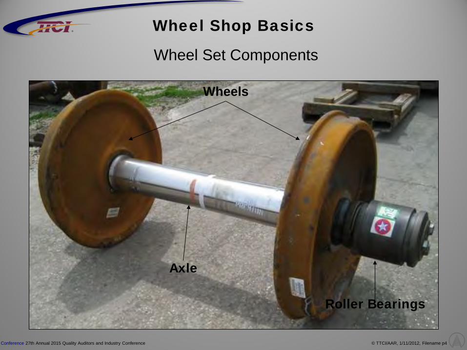
Conference 27th Annual 2015 Quality Auditors and Industry Conference © TTCI/AAR, 1/11/2012, Filename p4
®
Wheel Set Components
Wheels
Axle
Roller Bearings
Wheel Shop Basics

Conference 27th Annual 2015 Quality Auditors and Industry Conference © TTCI/AAR, 1/11/2012, Filename p5
®
Wheel
Flange
Tread
Rim
Hub
Plate
Wheel Shop Basics

Conference 27th Annual 2015 Quality Auditors and Industry Conference © TTCI/AAR, 1/11/2012, Filename p6
®
Axle
Body Wheel Seat Journal
Journal Fillet Journal Dust Guard
Cap Screw Hole
Axle Center
Wheel Shop Basics

Conference 27th Annual 2015 Quality Auditors and Industry Conference © TTCI/AAR, 1/11/2012, Filename p7
®
Bearing
Cup
Seal End Cap
End Cap Screws Backing Ring
Cone Assembly (Cage and Rollers)
Locking Plate
Wheel Shop Basics
Spacer

Conference 27th Annual 2015 Quality Auditors and Industry Conference © TTCI/AAR, 1/11/2012, Filename p8
® Wheel Shop Basics
Incoming Inspection (Wheel Sets)
• Wheel shops receive wheel sets by truck and/or railcar.
• The pictures illustrate several examples of wheel set securement devices not properly protected which shows metal to metal contact with the axle body and journal dust guard area.
• Wheel shops storage areas should be of sufficient size to arrange the storing of wheel sets.
• Storage tracks for serviceable wheel sets with bearings must be arranged so the flanges of one pair of wheels cannot strike the adjacent roller bearing housing or the body of the adjacent axle.
• Lifting devices must be protected with polymer pads or other methods to prevent damage to the axles and/or roller bearings.

Conference 27th Annual 2015 Quality Auditors and Industry Conference © TTCI/AAR, 1/11/2012, Filename p9
® Wheel Shop Basics
Incoming Inspection (Wheel Sets)
• Wheel sets should be unloaded and stored on rails
and/or hard surface if applicable. • Wheel sets should never be interlocked in storage
areas. • Disposition of the wheel sets is determined by the use
of an AAR Steel Wheel Gauge to measure tread and flange thickness.
• Minimum rim thickness readings for all size wheels are illustrated in the Field Manual Of The AAR Interchange Rules, Rule 41, Section B, Correct Repair Chart, under “Remarks”

Conference 27th Annual 2015 Quality Auditors and Industry Conference © TTCI/AAR, 1/11/2012, Filename p10
® Wheel Shop Basics
Incoming Inspection (Wheel Sets)
• Inspect wheels for defects and consider if the wheels are serviceable or scrap.
• Here are several pictures of wheel defects such as, Shelled Tread (WMC 75), Built-up Tread (WMC 76), and Slid Flat (WMC 78).
• Wheel sets need to be inspected for relevant Early Warning, Maintenance Advisory and any obsolete wheels per MSRP Section G-II, Rule 1.4.7.4 and AAR Field Manual.

Conference 27th Annual 2015 Quality Auditors and Industry Conference © TTCI/AAR, 1/11/2012, Filename p11
® Wheel Shop Basics
Bearing Dismount
• Remove cap screws from the bearing end cap.
• Ensure bearing pullers align evenly with end of journals to prevent damage.
• Remove the entire bearing assembly from journal.
• Ensure bearing dismount pullers are not causing
damage to dust guard / journal.
• Bearings should be placed on pallets and segregated by size for shipment.
• Bearings should be secured on pallets to prevent
spilling during shipment.

Conference 27th Annual 2015 Quality Auditors and Industry Conference © TTCI/AAR, 1/11/2012, Filename p12
® Wheel Shop Basics
Wheel Dismount
• Remove non serviceable wheels from axle.
• Protect journals with journal protectors during the dismounting process so damage does not occur to journals.
• Ensure journal ends are aligned properly with dismount push rams so damage and/or upset ends do not occur during the wheel dismounting process.
• Remove wheels from axle and process axle for inspection and/or storage.
• When dismounting pairs of wheels, both wheels must
be dismounted from the axle regardless of condition and the axle handled as a secondhand unmounted axle.
• This does not apply to “MISFIT” wheels that are misfitted in the mounting operation. Only the misfit wheel is required to be dismounted.

Conference 27th Annual 2015 Quality Auditors and Industry Conference © TTCI/AAR, 1/11/2012, Filename p13
®
• Before attempting to qualify axles, the axle ends, journals, journal fillets, dust guard seats and wear ring grooves must be thoroughly cleaned.
• Fillets with fretting, pitting, dents, or water etch that cannot be removed with abrasive cloth 80 grit or finer shall be refinished by grinding or machine cutting, providing the “U” and “W” dimensions meet tolerances.
• Journal Inspection and repair: • Journal defects shall be smooth blended into the
contour of the journal surface. • Journal finish measured across the D dimension at
interference fit surface must not excess 63 microinch. • Defects are allowed in cone seats as long as they
meet the following: • Average cone seat diameter is at least .0001”
above minimum. • Depression spanning an entire cone seat must not
exceed 1/8” wide at points of intersection with cone seat boundaries.
• Combined area of all depressions in each cone seat must not exceed 1 in².
Axle Cleaning and Inspection Wheel Shop Basics

Conference 27th Annual 2015 Quality Auditors and Industry Conference © TTCI/AAR, 1/11/2012, Filename p14
®
Axle Inspection
Checking on Centers
Alternate Method on Roller
Checking for Bent
Wheel Shop Basics
• Journals must be checked for out of round condition and the tolerance must not exceed .015”.
• journals must be checked for bent condition, tolerance is the distance between the two dial indicator points with the minimum reading being 5.5” and the maximum 10”.
• Journals to dust guard dimension (G & H) must be checked for runout and the tolerance must not exceed .006”.
• Journals must be checked for tolerance and must meet the requirements of Rule 1.2.4, Figure 4.4.
• Journal fillet must be inspected and meet the requirement of Figure 4.6. If a .005” feeler gauge can be inserted more than 3/8” down from the dust guard seat at all points around the periphery, the axle fillet must be corrected.
• Journals with seal wear rings must meet the requirements of
Rule 1.2.8.
• Journals must be checked for undercut condition and when identified, the undercut must be checked with a .005” wire or flat gauge with a point no wider than 1/16” and the deepest point of the undercut cannot exceed .005”, referenced from the inboard bearing seat.
Checking for G & H Dim.
Checking for Bent

Conference 27th Annual 2015 Quality Auditors and Industry Conference © TTCI/AAR, 1/11/2012, Filename p15
® Wheel Shop Basics
Axle Inspection
• All (E) 6 x 11 & (F) 6.5 x 12 axles must have dust guards checked for fitted application. Axles qualifying for fitted application will have fitted backing rings applied. Axles that do not qualify for fitted application will have UBR backing rings applied.
• Files must not be used on fillets or wheel seats.
• Wheel seats do not have to be cut before mounting provided they meet all specifications. They can be machine cut, ground, rolled or polished with abrasive cloth (80 grit or finer).
• Wheel seat must be checked for taper and out of round
condition. Check wheel seat not less than 3 points in its length and on 2 different diameters, the variation of these two measurements must not exceed .002”.
• As the wheel seat is measured from the journal end to
the center of the axle, at no point should the dimension decrease.
SH Dust Guard Minimum Diameters
Class Size Fitted UBR
E 6 x 11 7.030 6.980
F 6 ½ x 12 7.530 7.480
Taper cannot decrease
Taper measured in 3 spots

Conference 27th Annual 2015 Quality Auditors and Industry Conference © TTCI/AAR, 1/11/2012, Filename p16
®
• Machined and secondhand wheel seats, journals, and journal fillet portions of unmounted secondhand axles in freight car service must be magnetic particle tested by fluorescent (black light) before remounting.
• All personnel performing magnetic particle inspection will be qualified at a minimum to NDT Level I requirements as defined by SNT-TC-IA, latest addition.
• A detectability test must be performed weekly and a record kept. The test consists of inspecting a test axle with a know circumferential crack of at least 1” long or an equipment manufacturer’s approved test piece that will indicate.
• Proper brilliance of light source • Proper concentration of spray or bath solutions • Proper magnetic power source and operation of
equipment
• The test axle or test piece must be thoroughly cleaned of last test indicators before testing. The test must be verified with applicable light source before the test is started.
Magnetic Particle Testing
Wheel Shop Basics

Conference 27th Annual 2015 Quality Auditors and Industry Conference © TTCI/AAR, 1/11/2012, Filename p17
®
• Black lights used for inspection, the minimum acceptable intensity is 1000 µM/cm² at 15”.
Testing of axle:
• The magnetizing coil is brought over the center of the area to be tested.
• Magnetism is applied to the area at the same time as the spay or bath solution applied.
• Rotate the axle to ensure the entire surface is well covered.
• After thorough coverage of solution, the solution is cut off while current is on for a short interval (approximately 3 seconds), avoiding possible washing off of indications.
• If a time shot is used for particle application, then a minimum of two magnetizing shots during particle application will be required.
• Test with light source while slowly rotating the axle. • It’s recommended that the axle be rotated two
complete revolutions during inspection. • After axle is demagnetized, check axle for residual
magnetism with gauss meter. AAR will except 8 gauss or less.
Magnetic Particle Testing
Wheel Shop Basics

Conference 27th Annual 2015 Quality Auditors and Industry Conference © TTCI/AAR, 1/11/2012, Filename p18
® Wheel Shop Basics
Boring Mill
• Wheels are bored to fit a specific axle wheel seat. • Wheel bores must meet specified tolerances of
Section G-II. Boring mill must be corrected if tolerances cannot be maintained.
• A sufficient number of wheel bores must be checked
for taper and out of round. Wheel bores must not exceed .002”.
• The wheel bore must be sufficiently smaller than the
wheel seat diameter to enable the required mounting pressure. Generally this interference fit is .001” per inch of wheel seat diameter.
• Temperature difference between any two locations on
the two components must not exceed 25° F before boring.
• Wheel temperature at the center of the bore and the
axle temperature at the wheel seat must be within 15° F at time of mounting.

Conference 27th Annual 2015 Quality Auditors and Industry Conference © TTCI/AAR, 1/11/2012, Filename p19
® Wheel Shop Basics
Boring Mill • Two or more separate cuts must be made in boring
new steel wheels, one roughing and one finishing. If more than 1/4 in thickness is to be removed, two roughing cuts must be taken.
• If a single point finishing tool is used, the minimum
number of uniformly spaced grooves per bore is 30, with a maximum groove depth of .008”.
• A 1/8” radius or a 1/8” to 3/8” chamfer must be applied
at the entry or back of the hub of all finished bored wheels.
• New wheels must not be mated with secondhand
wheels and must meet the same AAR design criteria. • Alternative method for checking radial and plane test
must be performed on the first mounted wheel set of each diameter bored in production.
• Radial and plane runout on new wheels must not
exceed .030” on radial and .060” on plane.

Conference 27th Annual 2015 Quality Auditors and Industry Conference © TTCI/AAR, 1/11/2012, Filename p20
® Wheel Shop Basics
Wheel Mounting Press
• Wheel mounting press must be equipped with a dial pressure gauge and pressure recording gauge. The gauges must agree within 2%. These gauges must be used for every mounting operation.
• The pressure gauge must be checked for calibration at least once in each six months of service.
• The diagram of each wheel shall be marked to show identifying wheel number and wheel nominal bore.
• If the final wheel mounting pressure is not within pressure limits or an acceptable diagram as describe in G-II Figures 4.21 - 4.28, the mounting chart and corresponding wheel must be plainly marked “MISFIT”.
• All wheels must be within pressure limits. Mounting
diagrams that are 2 ton or less above the lower limit or 2 ton or less below the upper limit must be ideal mounts.
• An AAR approved mounting lubricant is applied to the entire wheel bore and half the axle wheel seat to prevent scoring.

Conference 27th Annual 2015 Quality Auditors and Industry Conference © TTCI/AAR, 1/11/2012, Filename p21
® Wheel Shop Basics
Wheel Mounting Press • Wheels must be mounted centrally with respect to the
axle center line within tolerance of 3/32”.
• New wheels mounted on the same axle must be the same tape size and bear the same tape size markings and secondhand wheels should be within one tape number in circumference.
• After wheels are mounted, they must be checked for back to back tolerance at three equidistant points. With automated equipment, every tenth pair must be checked.
• If the back to back gage is correct at one place on the wheel set and the radial and plane error is within specification, the wheel set is suitable for service. If not within specification, then the wheels must be dismounted.
• Misfits must be demounted and recorded in a log
showing their disposition. Wheel mounting diagrams and misfit logs must be kept for 10 years.

Conference 27th Annual 2015 Quality Auditors and Industry Conference © TTCI/AAR, 1/11/2012, Filename p22
® Wheel Shop Basics
Wheel Lathe
• For wheels to qualify for service without recontouring, all secondhand freight car wheels must meet specifications of the Field Manual Of The AAR Interchange Rules, Rule 41.
• Wheels intended for service without recontouring
wheel tread must be checked for out of round condition and wheel tread must be within .030”. If not, wheel tread must be recontoured or scrapped.
• Freight car wheels must be checked for back to back
measurement before contouring. Wheels with less than 52 15/16” or more than 53 3/16” are out of gauge an should not be contoured.
• Heat-treated wheels must be paint stenciled with an
“H” on the front plate of wheel. • Wheel tooling feed marks must not exceed 1/8” wide
at any place on the wheel tread or flange contour. • Recontoured wheels must be within one tape
circumference number. • Recontoured flange thickness of a wheel set must
not vary more than 2/16”.

Conference 27th Annual 2015 Quality Auditors and Industry Conference © TTCI/AAR, 1/11/2012, Filename p23
® Wheel Shop Basics
Wheel Lathe Process
• Recontoured wheel tread and flange contours must be in accordance with the gages shown in the G-II Manual.
• Recontoured wheels must have the entire defect
removed from the wheel. • Recontoured wheels must be measured with the steel
wheel gauge to ensure minimum rim thickness requirements are met.
• Recontoured wheels with a witness groove, must have
the groove measured with a steel wheel gauge for tolerance. The depth of the witness groove no more than 3/64” deep and not less than 3/8”.
• Radial and plane runout on recontoured wheels must not exceed .030” on radial and .045” on plane.

Conference 27th Annual 2015 Quality Auditors and Industry Conference © TTCI/AAR, 1/11/2012, Filename p24
® Wheel Shop Basics
UT (Re-Profiled Wheels)
• Recontoured freight car wheels must be ultrasonically tested after turning to qualify for reapplication to interchange service.
• An Automated ultrasonic flaw detection system can be operated by any individual as long as it meets the following criteria:
• Must sense proper functionality (All sensors are operational)
• Must detect and improper test (Loss of water path) • Must capture C-scans representation of test and data
for 10 years • Must indicate pass or fail or no test • A wheel set can only be moved out of testing area to
a defined location based on the test results
• An ultrasonic flaw detection system that does not meet the requirements of an automated flaw detection system must be operated by NDT Level I at a minimum. NDT Level II are required for calibration.

Conference 27th Annual 2015 Quality Auditors and Industry Conference © TTCI/AAR, 1/11/2012, Filename p25
® Wheel Shop Basics
UT (Re-Profiled Wheels)
• Calibration of ultrasonic flaw detection systems must be performed by NDT Level II. Calibration includes modification of any software parameters or physical components that affect device output.
• A calibration check of an automated flaw detection system is verification that the machine is
within tolerance by using a calibration standard and checking that the output is at prescribe range of acceptable performance. Calibration checks must be performed by NDT Level I at a minimum.
• System and calibration checks must duplicate normal practice including surface condition and
couplant.
• If the results of a system or calibration check are outside of system tolerance then an assessment of previous inspections must be made and actions taken.
• Any wheel with a flaw indication equal to or greater than 25% of the reference standard at
depths of 1/2” to 7/8” and 50% of the reference standard at depths of 7/8” to 2” shall be cause for rejection and wheels scrapped.

Conference 27th Annual 2015 Quality Auditors and Industry Conference © TTCI/AAR, 1/11/2012, Filename p26
® Wheel Shop Basics
UT Process Secondhand Axles (Loose and Mounted Axles)
• NDT personnel performing radial ultrasonic inspection operations on axles must be prequalified to Non destructive testing NDT Level I at a minimum.
• Inspection surface must be free of all dirt and grit prior to
start of testing.
• For a loose axle, the system must be setup on the wheel seat for testing the journal and wheel seat, and set up on the body for testing the body portions of the axle to exhibits an 80% full screen height indication for backface reflection at the thickest part.
• For a mounted axles, the system must be setup on the
journal for testing the journal portion, and setup on the body for testing the body portions of the axle to exhibits an 80% full-screen height indication for backface reflection at the thickest part.

Conference 27th Annual 2015 Quality Auditors and Industry Conference © TTCI/AAR, 1/11/2012, Filename p27
® Wheel Shop Basics
UT Process Secondhand Axles (Loose and Mounted Axles)
• When a change to the equipment power source, transducer, operator, or coaxial cable occurs, the system setup must be verified.
• The same couplant must be used for calibration and examination.
• The variation in cross-section of the axle may produce spurious indications. These expected
indications must be recognized and are not cause for reject.
• Scan the entire length of the axle radially through the diameter along two lines with and offset of approximately 90°.
• The axle will be rejected for a location if a loss of back reflection of 80% or greater is experienced.
• The largest loss of backface reflection on an axle (0 - 79%) must be measured from the serial
end of the axle to the indication and recorded. • Areas under cap screws and fillets need not be tested.

Conference 27th Annual 2015 Quality Auditors and Industry Conference © TTCI/AAR, 1/11/2012, Filename p28
®
Wheel Shop Basics
Bearing Mount Press
• Bearing mounting press must be equipped with a pressure gauge that reads in tons and must be checked for calibration at least once in each six months of service.
• Before proceeding with bearing application, the wheels, axle and roller bearings should be approximately the same temperature.
• Ensure bearings have the same certificate number mounted on the same axle.
• Verify that axle ends and journals are clean and free of dirt
and contaminates just prior to coating.
• Apply a moderate to heavy coat coating of approved rust preventive to journal fillet and dust guard area.
• Coat the journal with caster oil or heavy SAE 40 or SAE 50 mineral oil.
• While bearings are being applied, ensure mounting sleeves are properly aligned with end of axle.

Conference 27th Annual 2015 Quality Auditors and Industry Conference © TTCI/AAR, 1/11/2012, Filename p29
® Wheel Shop Basics
Bearing Mount Press
• Mount bearings to the appropriate tonnage. Bearing press must be equipped with a relief valves so that a specified pressure can be maintained for a short interval to ensure bearings are properly seated.
• Visually inspect tapped holes in the end of axle for tread
damage, dirt and corrosion; clean if necessary.
• Apply end cap, end must be of the same manufacturer and AAR approval number as the bearing being applied, unless a colored locking plate is used “Interchangeability of end caps”.
• Using torque wrench, run up cap screw to less than prescribe torque values, then with a slow steady force, tighten cap screws in sequence until no further movement of the specified torque.
• Torque wrenches should be checked frequently
(preferably daily) to ensure correct readings and must be check weekly with a record kept.
Class Journal Size Seating Pressure
For Freight Car
D 5 1/2 x 10 50 tons +/- 5
E 6 x 11 50 tons +/- 5
F 6 1/2 x 12 50 tons +/- 5
K 6 1/2 x 9 50 tons +/- 5
G 7 x 12 65 tons +/- 5
Class Journal Size Torque (Ft. lbs.)
For Freight Car
D 5 1/2 x 10 160
E 6 x 11 290
F 6 1/2 x 12 420
K 6 1/2 x 9 420
G 7 x 12 490

Conference 27th Annual 2015 Quality Auditors and Industry Conference © TTCI/AAR, 1/11/2012, Filename p30
® Wheel Shop Basics
Bearing Mount Press
• Automated torque systems must be approved by the AAR and a copy of the approval maintained in the facility.
• Bearings are checked for mounted lateral by rotating the bearing one complete revolution before lateral reading is taken. Lateral reading must be within manufacturer’s tolerances.
• Roller bearings must be protected during mounting against
contaminates from dirt, sand, water, etc.
• Effective January 1, 2012, E and F class axles meeting the minimum dust guard “H” dimension tolerance must have fitted backing rings applied. Axle with undersized dust guard tolerance must have an approved universal fitted backing ring applied.
• Effective July 1, 2012 bar code labels must be affixed to all freight car wheel sets in accordance with MSRP Section F, S-920.
Mounted Bearing Lateral
.001” - .015”

Conference 27th Annual 2015 Quality Auditors and Industry Conference © TTCI/AAR, 1/11/2012, Filename p31
® Wheel Shop Basics
Shipping
• Wheel sets are shipped to customers by truck or railcar.
• When handling pairs of mounted wheels, care should be taken that handling devices do not damage the axle and/or roller bearings.
• All serviceable sets must be shipped using methods that prevent the axle body and roller bearing from having metal to metal contact with load securement devices and other wheel sets.
• All completed wheel sets must have a CEPM label affixed to the outside of one wheel plate.
• All completed wheel sets shipped must be registered with Railinc.
• Wheel sets should be final inspected before shipping to ensure wheel sets meet requirements.

Conference 27th Annual 2015 Quality Auditors and Industry Conference © TTCI/AAR, 1/11/2012, Filename p32
® 27th Annual 2015 Quality Auditors and Industry Conference
QUESTIONS