wheel detector installation manual rev 4-2railswitchservice.com/resources/wdmanrev42.pdf · rail...
TRANSCRIPT

Rail Switch Service LLC. Wheel Detector Installation Manual
Page 1 of 1
Contents
Introduction 2
Wheel Detection System Features 6
Pre-Installation Considerations 7
Important: Installation Guidelines 7 & 8
General Installation Notes 12
Bolted Bracket Installation 12
Direct Bolting to Rail Installation 34
Cable Connection to the Main Module 38
Power Up and Testing 45
Read this manual in its entirety before beginning the installation of the Wheel Detector System.
Rail Switch Service LLC. 1915 Lane Rd.
Paducah, KY. 42003 Ph: (270) 442-5090 Fax: (270) 444-9717

Rail Switch Service LLC. Wheel Detector Installation Manual
Page 2 of 2
Introduction:
The Rail Switch Service LLC. Wheel Detection System was developed to provide a presence detection system that is simple to install, highly reliable and easy to maintain.
The Wheel Detection System enables the user to easily configure the size of his protected zone to meet the specific needs of his application. Clearance point protection, on the trailing side of the points, and adequate facing point protection for the speed of the rail traffic is easily accomplished by proper placement of the Wheel Detection sensors.
The Wheel Detection System is easily integrated into the operation of typical DC electric Switch Machines. The Wheel Detection System is also designed to operate as a stand-alone system to allow ease of interfacing with other manufacturers’ equipment.
The Wheel Detection System is offered in 2-detector versions (300/2), 3-detector versions (300/3) and 4-detector versions (300/4) as standard packages. Additional sensor locations can be easily added to enable the user to have a detection system with up to 28 detectors per “main module”.
The 2-detector system is normally used for the protection of Derail/Blue Flag applications. The 3-detector system is normally used in a conventional turnout. The 4-detector system is normally used to protect both switches in a crossover application. Variations and special track geometry are easily accommodated through the use of additional wheel sensors.

Rail Switch Service LLC. Wheel Detector Installation Manual
Page 3 of 3
The Wheel Detection System is made up of (3) major components.
The “main module” acts as the interface between the wheel sensors and the Switch Machine. It is also the main processing unit for the Wheel Detection System. The “main module” operates from 8 to 24 VDC with 30 mA current draw. The main module is located inside the Switch Machine enclosure when used in conjunction with most Switch Machines. No external enclosures are required for the RTI Wheel Detection System.

Rail Switch Service LLC. Wheel Detector Installation Manual
Page 4 of 4
The wheel sensors are located at the rail and are the devices that sense the presence of a railroad wheel over them. The optimum placement of the sensor is 1-3/4" (+0.00" –1/16") below the top of the rail. The sensor will operate on a voltage range from 8 to 24 VDC at 32 mA current draw per sensor.
Rail Switch Service LLC. Wheel Detector Installation Manual
Page 5 of 5
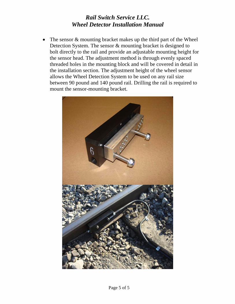
The sensor & mounting bracket makes up the third part of the Wheel Detection System. The sensor & mounting bracket is designed to bolt directly to the rail and provide an adjustable mounting height for the sensor head. The adjustment method is through evenly spaced threaded holes in the mounting block and will be covered in detail in the installation section. The adjustment height of the wheel sensor allows the Wheel Detection System to be used on any rail size between 90 pound and 140 pound rail. Drilling the rail is required to mount the sensor-mounting bracket.

Rail Switch Service LLC. Wheel Detector Installation Manual
Page 6 of 6
Connection of the Wheel Detection system is accomplished using 4-conductor (2 twisted pairs) #18 gauge shielded wire (furnished by Railway Technology Inc.). This wire is of direct burial construction. It is recommended that the wire runs between the wheel sensor and the main module be buried to minimize damage to the wire from vandalism or abuse. Burying the wire also makes track maintenance easier since the wire is not in the way of tamping or other track maintenance operations. The #18 gauge wire is adequate in size to allow wheel sensor locations as far as 2000 ft. away from the “main module”.
Wheel Detection System Features
The Wheel Detection system is designed to “Fail-Safe”. The wheel sensors are designed so in the unlikely event they become loose on their mounting bracket or are torn away from the rail; the main module will fail to the condition that disables further Switch Machine operation. The loss of a wire or connection will result in the same Fail-Safe failure mode. A power loss to the Wheel Detection system will also result in a Fail-Safe failure mode preventing further Switch Machine operation.
The outputs on the main module include redundant circuitry and componentry. The operating logic and circuitry is designed so that if a failure occurs on either of the redundant outputs, the main module fails in the safe condition preventing further operation of the Switch Machine.
The operating logic used in the Wheel Detection System includes both “Auto-Line” functions and “Missed Wheel Compensation” to enhance the flexibility of the Wheel Detection System.
Sensors used on the trailing side of the points can be programmed through the software to generate a pulsed output to allow the automatic lining of the Switch Machine to correspond to the trailing side routing movement of the train or rail traffic. This function prevents run-throughs of the switch points from occurring.
The operating logic of the “main module” includes the software selectable ability to compensate for false signals as the result of dragging metal objects over the wheel sensor in such a manner as to generate a false wheel count. This feature is the “Missed Wheel Compensation” function.

Rail Switch Service LLC. Wheel Detector Installation Manual
Page 7 of 7
A complete description of the operation of both features is included later in this manual.
Pre-Installation Considerations
Prior to beginning the installation phase of the Wheel Detection System, it is necessary to determine the proper locations for the wheel sensors. Train speeds, track geometry, and clearance requirements all factor into the number of wheel sensors required and the location of each wheel sensor.
(3) Wheel sensors are usually an adequate number of sensors to protect a conventional turnout. (1) Sensor would be located on the facing side of the points, (1) sensor would be located on the normal routing of the trailing side of the points and (1) sensor would be located on the reverse routing of the trailing side of the points. The wheel sensors on the trailing side of the points are also usually located at the sideswipe clearance point to eliminate a sideswipe potential.
The facing point wheel sensor location is based on the maximum expected train speed and the maximum time required for the Switch Machine to throw. For example, a train traveling 10 mph is moving at 14.66 feet per second. The maximum time required by a typical Switch Machine to throw in a worst-case scenario is 3 seconds. Therefore, 14.66 feet per second times 3 seconds results in the need to locate the facing side wheel sensor a minimum distance of 44 feet in front of the switch points.
In some instances, track geometry requires the use of several wheel sensors to provide the protection needed around a switch. The RSS “main module” will support up to (28) wheel sensors. This number of wheel sensors is more than adequate to provide a protection zone for even the most unusual and complicated track geometries.
Installation Guidelines:
These guidelines must be strictly followed to ensure trouble free operation of the wheel counter system.
1. Do not install wheel sensors on closure rails leading into or out of rail frogs. This location has historically caused more system lock-ups than any other incorrect install location. Dragging hoses or

Rail Switch Service LLC. Wheel Detector Installation Manual
Page 8 of 8
equipment will swipe across and strike the wheel sensors installed in these locations adding unwanted counts and damaging the wheel sensors that usually results in locking the system up.
2. Do not install wheel sensors within 15 feet of rail joints, joint bars or other rail structure that will have high levels of shock/vibration. Moving the wheel sensor to increase the protection zone is usually the best choice to avoid the rail structure.
3. Do not install the wheel sensors near any moving rail structure (switch points), 3 feet should be maintained to ensure no interference with normal operation.
4. The distance between the entry and exit wheel sensors of any protected zone must be greater than the distance between the axles of the longest rail cars.
5. Always maintain a minimum of 3 feet radius between any other wheel sensors, even if the sensors are separated by a rail, to avoid interference and communication issues.
6. Always install the wheel sensors securely to the rail at the proper factory recommended height.
7. Always be sure to inspect the final wiring of the wheel sensors to ensure that the wires are not routed over the orange release buttons.
8. Always use the factory supplied or factory recommended wheel counter cable. Do not use a solid conductor cable with the wheel counter system, stranded cable, shielded, minimum of 18 gauge only.
9. The inner shields of the wheel counter cable should have continuous connection from sensor to sensor when being daisy chained and connected to N12 (battery negative) inside the switch machine. The end run sensors shield wires should not be connected to anything and can be cut off at the insulation of the cable.
10. Always use factory supplied or factory recommended cable cord grips and connectors that will keep dirt, water and contaminates from entering the wheel sensors.

Rail Switch Service LLC. Wheel Detector Installation Manual
Page 9 of 9
The wheel sensors and main modules are shipped with even ID numbers programmed into them. The even ID numbers require an installation of the wheel sensor on the right side of the tracks when facing the switch. This is the standard configuration of the wheel sensors.
This photo shows the correct “right side”orientation of the sensor when facing the switch. The installation of the sensor on the right side is true regardless of whether the installer is facing the switch from the facing or trailing side of the points.
The wheel sensors may be installed on the left side of the tracks when facing the switch to avoid rail joints or other rail structure. However, this requires programming the sensor and main module with an odd ID number. The combination of the ID number and the side of the tracks the sensor is

Rail Switch Service LLC. Wheel Detector Installation Manual
Page 10 of 10
installed on is what enables the sensor to know when a train is entering or exiting a protected zone. For this reason, the location and ID number guidelines must be adhered to. The ID number can easily be changed using the factory supplied software and programming cable. If the ID numbers are changed from the factory set even ID number, the important item is that the Sensor ID numbers MUST match the ID numbers in the main module. ID numbers start at #4 and end at #28. Any ID number, even or odd, can be used in this range. The software used to change the ID numbers is available at our website at www.railswitchservice.com
Following are recommended locations of wheel sensors for several typical layouts. Please contact RSS for assistance in determining wheel sensor locations for your application.

Rail Switch Service LLC. Wheel Detector Installation Manual
Page 11 of 11
Derail
wheel sensor ID # 4
Switch Machine
wheel sensor ID # 6
wheel sensor ID # 8
wheel sensor ID # 6
Derail
wheel sensor ID # 4
Right and Left Hand switches
wheel sensor # 4
wheel sensor ID # 6
wheel sensor ID # 10Cross-Over
wheel sensor ID # 8
Switch Machine
Switch Machine
Rail Switch Service LLC. Wheel Detector Installation Manual
Page 12 of 12
General Installation Notes
There are two methods used to attach the wheel sensors to the rail. The first and preferred method is to drill the web of the rail at the AXIS point and mount the aluminum adjustment block to the rail. This adjustment block allows easy height adjustment of the wheel sensor. This method is recommended unless the customer prefers the second method.
The second method is to bolt the wheel sensors to the rail with a temporary mounting bracket that bolts to the rail without drilling. These bolt on brackets are typically used in temporary installation or during emergency situations where there is not enough track time to drill the rail.
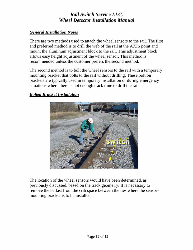
Bolted Bracket Installation
The location of the wheel sensors would have been determined, as previously discussed, based on the track geometry. It is necessary to remove the ballast from the crib space between the ties where the sensor-mounting bracket is to be installed.
Rail Switch Service LLC. Wheel Detector Installation Manual
Page 13 of 13
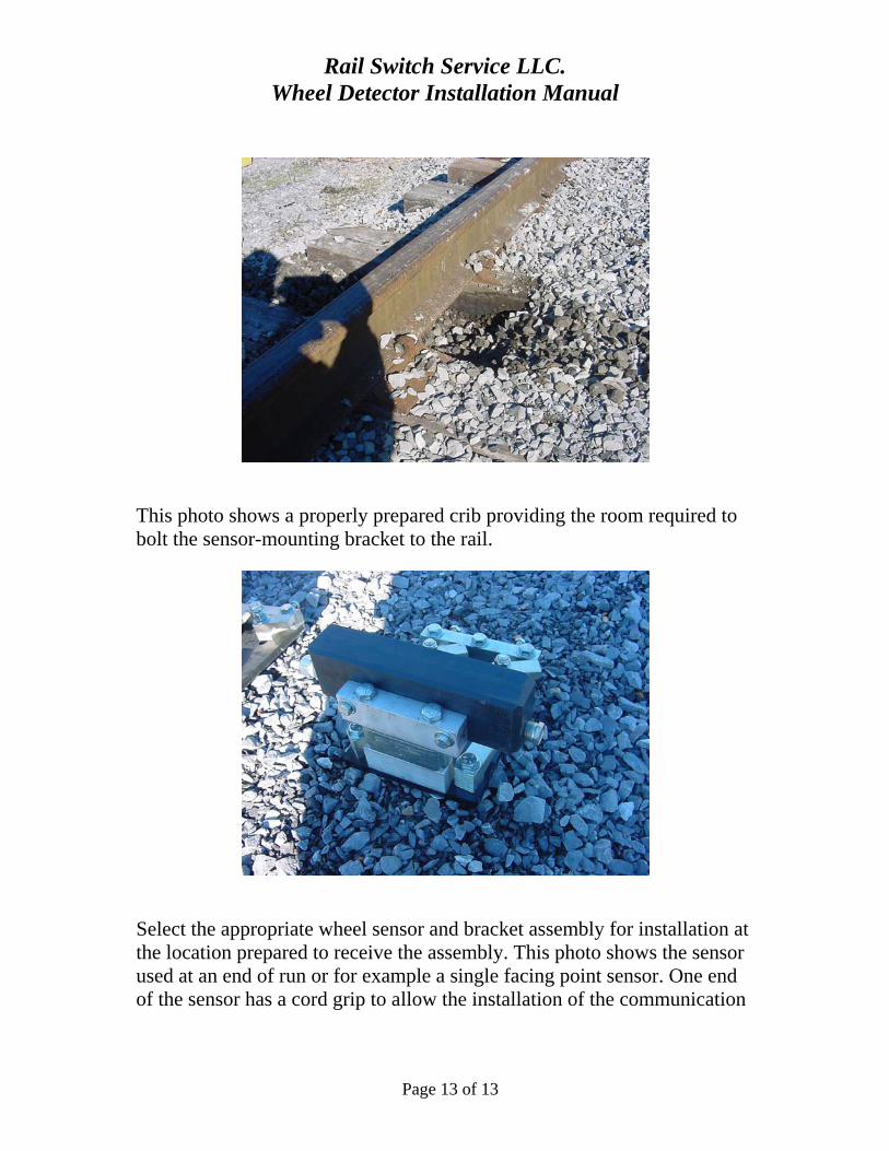
This photo shows a properly prepared crib providing the room required to bolt the sensor-mounting bracket to the rail.
Select the appropriate wheel sensor and bracket assembly for installation at the location prepared to receive the assembly. This photo shows the sensor used at an end of run or for example a single facing point sensor. One end of the sensor has a cord grip to allow the installation of the communication
Rail Switch Service LLC. Wheel Detector Installation Manual
Page 14 of 14
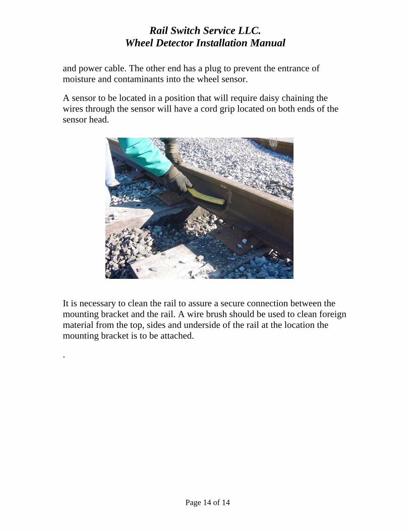
and power cable. The other end has a plug to prevent the entrance of moisture and contaminants into the wheel sensor.
A sensor to be located in a position that will require daisy chaining the wires through the sensor will have a cord grip located on both ends of the sensor head.
It is necessary to clean the rail to assure a secure connection between the mounting bracket and the rail. A wire brush should be used to clean foreign material from the top, sides and underside of the rail at the location the mounting bracket is to be attached.
.

Rail Switch Service LLC. Wheel Detector Installation Manual
Page 15 of 15
The wrenches required to install the sensor and bracket assembly are 9/16" and 3/4". In addition a Combination Square with a bubble level will be needed to set the height of the wheel sensor.
Remove the sensor assembly from the mounting bracket rail plate.

Rail Switch Service LLC. Wheel Detector Installation Manual
Page 16 of 16
The sensor head assembly includes the wheel sensor, the spacer kit, mounting bar and associated bolts, washers and nylock nuts. Removal of this assembly is necessary to allow the installer to attach the baseplate to the underside of the rail.
It is necessary to rotate the clamp hooks so that they are parallel with the rail. This provides the clearance required to place the baseplate firmly in contact with the underside of the rail. The bolts on the clamp hooks should

Rail Switch Service LLC. Wheel Detector Installation Manual
Page 17 of 17
be lightly tightened so that they are not floppy loose but are loose enough to be rotated by hand.
Place the baseplate assembly beneath the rail in the crib space area previously cleared away.
The clamp hooks should be rotated so that they extend over the base of the rail. It may be necessary to loosen the clamp hooks slightly on larger rail sizes in order to allow for the clearance needed to rotate the clamp

Rail Switch Service LLC. Wheel Detector Installation Manual
Page 18 of 18
hooks over the base of the rail. At this point the baseplate should be fully supported by the clamp hooks.
Begin tightening the take-up bolts located on the thrust bar on the field side of the baseplate. This action will snug the clamp hooks up against the sides of the base of the rail.
Tighten the take-up bolts until there is no gap between the side of the rail base and the inside of the clamp hooks.

Rail Switch Service LLC. Wheel Detector Installation Manual
Page 19 of 19
Tighten the jam nuts after the take-up bolts have been tightened enough to eliminate the clearance between the base of the rail and the clamp hooks.
Securely tighten the bolts that hold the clamp hooks to the baseplate. Be sure to tighten all (4) clamp hook bolts evenly.
Rail Switch Service LLC. Wheel Detector Installation Manual
Page 20 of 20
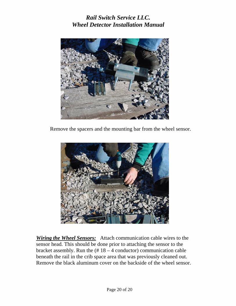
Remove the spacers and the mounting bar from the wheel sensor.
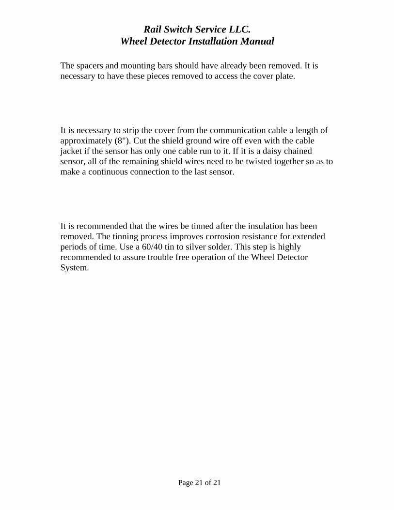
Wiring the Wheel Sensors: Attach communication cable wires to the sensor head. This should be done prior to attaching the sensor to the bracket assembly. Run the (# 18 – 4 conductor) communication cable beneath the rail in the crib space area that was previously cleaned out. Remove the black aluminum cover on the backside of the wheel sensor.
Rail Switch Service LLC. Wheel Detector Installation Manual
Page 21 of 21
The spacers and mounting bars should have already been removed. It is necessary to have these pieces removed to access the cover plate.
It is necessary to strip the cover from the communication cable a length of approximately (8"). Cut the shield ground wire off even with the cable jacket if the sensor has only one cable run to it. If it is a daisy chained sensor, all of the remaining shield wires need to be twisted together so as to make a continuous connection to the last sensor.
It is recommended that the wires be tinned after the insulation has been removed. The tinning process improves corrosion resistance for extended periods of time. Use a 60/40 tin to silver solder. This step is highly recommended to assure trouble free operation of the Wheel Detector System.

Rail Switch Service LLC. Wheel Detector Installation Manual
Page 22 of 22
Insert the stripped wire through the cord grip on the end of the wheel sensor. Insert the wires into the spring cage connector by pushing the stripped wire ends into the appropriate terminals.
Terminal 1 = white wire, pair 1
Terminal 2 = black wire, pair 1
Terminal 3 = black wire, pair 2
Terminal 4 = white wire, pair 2
NOTE: Route the wires so that they do not cross over the orange release tabs on the spring cage connector. If this step is not observed, sensor communication problems will be likely at a later date.
Tighten the cord grips to attain a secure and watertight joint where the wire goes into the wheel sensor. The cord grip should tighten around the cable jacket. A watertight seal is not possible unless the cable jacket is inserted through the cord grip.

Rail Switch Service LLC. Wheel Detector Installation Manual
Page 23 of 23
This photo shows correctly installed wires on one side of a wheel sensor that will next be wired in a daisy chain fashion. Notice that none of the connected wires are routed over the orange release buttons on the connectors. This wire arrangement is used typically on the trailing side of the points to connect the reverse wheel sensor with the normal sensor.

Rail Switch Service LLC. Wheel Detector Installation Manual
Page 24 of 24
This photo shows the installer pushing the wire into the spring cage connector. Always tug on the wire, after pushing the wire into the connector, to assure a good “bite” of the spring cage on the wire.

Rail Switch Service LLC. Wheel Detector Installation Manual
Page 25 of 25
This photo shows a properly wired wheel sensor used in a daisy chain application. A non daisy chain application would have the wires connected to only one connector.
Rail Switch Service LLC. Wheel Detector Installation Manual
Page 26 of 26
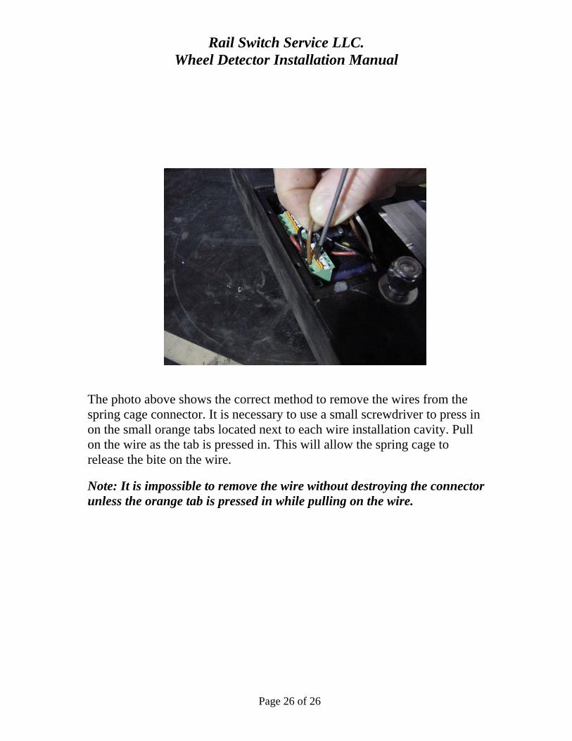
The photo above shows the correct method to remove the wires from the spring cage connector. It is necessary to use a small screwdriver to press in on the small orange tabs located next to each wire installation cavity. Pull on the wire as the tab is pressed in. This will allow the spring cage to release the bite on the wire.
Note: It is impossible to remove the wire without destroying the connector unless the orange tab is pressed in while pulling on the wire.

Rail Switch Service LLC. Wheel Detector Installation Manual
Page 27 of 27
Re-install the cover plate after all wires have been checked for a good connection and the oxide inhibitor grease (supplied) has been applied.
Note: Application of the supplied oxide inhibitor grease is very important to the long term reliability of the system.
Rail Switch Service LLC. Wheel Detector Installation Manual
Page 28 of 28
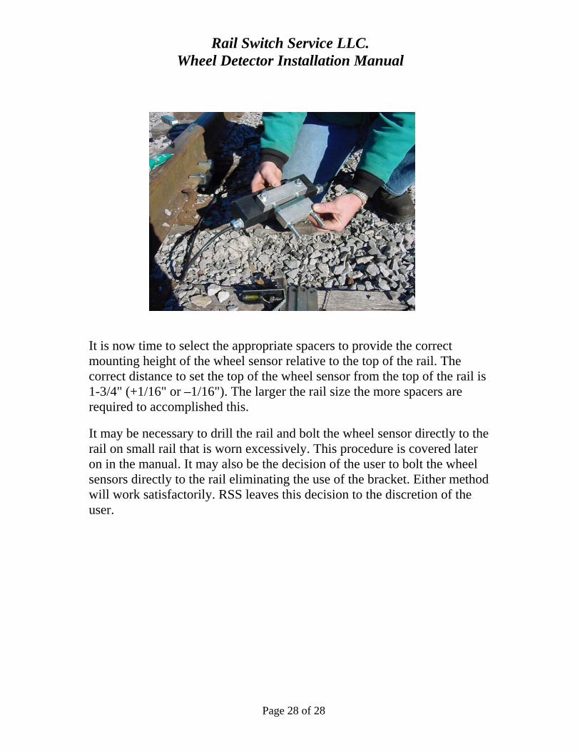
It is now time to select the appropriate spacers to provide the correct mounting height of the wheel sensor relative to the top of the rail. The correct distance to set the top of the wheel sensor from the top of the rail is 1-3/4" (+1/16" or –1/16"). The larger the rail size the more spacers are required to accomplished this.
It may be necessary to drill the rail and bolt the wheel sensor directly to the rail on small rail that is worn excessively. This procedure is covered later on in the manual. It may also be the decision of the user to bolt the wheel sensors directly to the rail eliminating the use of the bracket. Either method will work satisfactorily. RSS leaves this decision to the discretion of the user.

Rail Switch Service LLC. Wheel Detector Installation Manual
Page 29 of 29
Place the wheel sensor and spacers on the baseplate. Use a Combination Square that includes a bubble level to aid in the selection of the appropriate spacers. RTI includes spacers of different thickness to accommodate the different size rails normally encountered. Hold the Combination Square against the top and side of the ball of the rail. The Combination Square should be adjusted to 1-3/4" . Spacers should be added or removed as necessary to allow the top of the wheel sensor to touch the end of the Combination Square blade.

Rail Switch Service LLC. Wheel Detector Installation Manual
Page 30 of 30
Make sure that the Combination Square is level when the determination of the spacers required for the 1-3/4" clearance is made.

Rail Switch Service LLC. Wheel Detector Installation Manual
Page 31 of 31
After determining the correct number of spacers required for the installation of the wheel sensor, it is necessary to place the unused spacers beneath the baseplate. The spacers located on the bottom are required to assure that the spacer stack is securely tightened before the thread limit is reached on the bolts.
Tighten the bolts that secure the spacer assembly. Recheck the height of the wheel sensor from the top of the rail to assure that the 1-3/4" distance is still maintained.
Note: Do not make direct vertical cable runs to the Wheel Sensors. Always allow extra cable to accommodate track heaving and future Wheel Sensor replacement.

Rail Switch Service LLC. Wheel Detector Installation Manual
Page 32 of 32
The cable should be either secured to the top of the ties or buried at a location that will allow normal track maintenance to occur without contact of the cable being possible. RTI strongly recommends that the communication cable from the wheel sensors be buried. This is the most secure and trouble free method of installing the cable for long term operation. Attaching the cable to the ties should be used in applications where the wheel sensors are being installed for test or short-term purposes.

Rail Switch Service LLC. Wheel Detector Installation Manual
Page 33 of 33
This photo shows a completed install of a wheel sensor. The ballast has been replaced with the communication cable neatly tucked alongside the wheel sensor.

Rail Switch Service LLC. Wheel Detector Installation Manual
Page 34 of 34
Direct Rail Mount Method:
Direct rail mount is the preferred mounting method because it eliminates the maintenance schedule usually needed for the bolt-on bracket assemblies.
The rail will need to be drilled, two ½” holes at 4-1/2” spacing in the axis point of the rail web for each wheel sensor in the protection zone. After drilling, the rail mount adapter can be bolted to the rail. Note that the rail mount adapters mounting holes are offset so the device can position the sensor mounting holes high or low to accommodate many different rail sizes
Refer to “Wiring the Wheel Sensors” starting on page 20 to complete the internal wiring of the wheel sensors.

Rail Switch Service LLC. Wheel Detector Installation Manual
Page 35 of 35
After the wiring procedure, be sure to properly route the wires “around” the orange disconnect buttons and use the supplied die-electric grease to preserve the wire connection.
The wheel sensor can now be bolted to the rail mount adapter. Using a combination square with a bubble level, determine which threaded hole sets will place the wheel sensor at the 1-3/4” recommended height.

Rail Switch Service LLC. Wheel Detector Installation Manual
Page 36 of 36
When the proper threaded holes have been determined the wheel sensor can be final tightened to the rail mount adapter.
As shown in the above photo, leave enough extra cable so as to allow movement of the rail and re-wiring of wheel sensors in future.
Rail Switch Service LLC. Wheel Detector Installation Manual
Page 37 of 37

Rail Switch Service LLC. Wheel Detector Installation Manual
Page 38 of 38
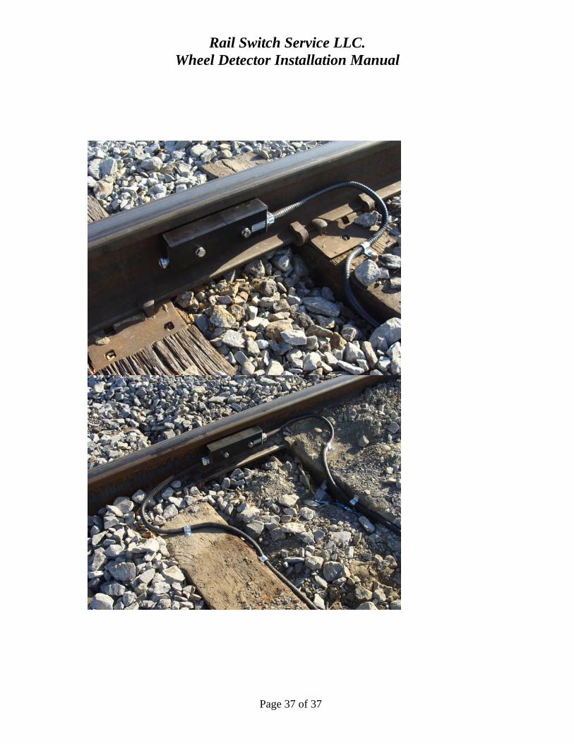
The photos above show the completed installation of wheel sensors bolted directly to the rail. One of the advantages of direct bolting the sensor to the rail is the ability to locate the sensor over a tie. This is not possible with the bolt-on bracket assembly
Power and Communication Cable connection to the Main Module
The main module is usually installed inside the Switch Machine enclosure on a short piece of DIN rail included in the “Machine Kit”. The main module connector is pre-wired from the factory to ease in the interface wiring of the Switch Machine. The main module connector, wiring harness, system fuse holder, and DIN rail with adhesive back are all located in the parts bag marked “Machine Kit, PN 300/MK”.
Please refer to Main Module Wiring Schematic on page 39 for specific wire terminations.

Rail Switch Service LLC. Wheel Detector Installation Manual
Page 39 of 39
TITLE
300/3
PAGE
1 OF 3
DATE
3/26/2008
DESCRIPTION
ELECTRICAL SCHEMATIC - WHEEL DETECTOR MODULE
R A I L W A Y T E C H N O L O G Y , I N C O R P O R A T E D
MICRO CONTROLLERPart # 310050-01D
17
18
19
9
10
11
26
27
12
13
14
15
16
20
21
22
23
24
25
1
2
3
4
5
6
7
8
27
27
28
28
29
BATTERY NEGATIVE (COMMON)
OUTPUT SUPPLY - 12VDC @ 10A
LOGIC SUPPLY - 12VDC @ 1A
NORMAL COMMAND
TOGGLE COMMAND
REVERSE COMMAND
THROW DISABLE PIN 4
AUXILIARY NORMAL COMMAND
AUXILIARY TOGGLE COMMAND
AUXILIARY REVERSE COMMAND
THROW DISABLE PIN 8
PRESSURE SWITCH
NORMAL PROXIMITY SENSOR
REVERSE PROXIMITY SENSOR
SELF RESTORE ACTIVATE
SELF RESTORE DETECT
AUXILIARY NORMAL CONFIRMATION
AUXILIARY REVERSE CONFIRMATION
NORMAL SOLENOID
REVERSE SOLENOID
MOTOR SOLENOID
MACHINE DISABLE ALARM
MACHINE FAULT ALARM
COMMUNICATION FAULT
NORMAL INDICATION
GAPPED POINT INDICATION
REVERSE INDICATION
STROBE LIGHT
BULB FAIL DETECT (ACTIVE LOW)
OUTPUT SUPPLY - 12VDC @ 10A
THIS SHEET SHOWS THE WIRING FOR
THIS OPTION ONLY. REFER TO BASIC
MACHINE SCHEMATIC FOR MACHINE
CONNECTIONS.
Note: When power is first applied or Wheel Detection Module isprogrammed it must be reset to enable the Switch Machine.
Wheel CounterReset.
Optional
1 2 3 4 5 6 7 8 9 10 11 12 13 14 15 16
300/001MAIN MODULE
4 5 6 7 8 9
-12V
DC
+12
VD
C
TERMINALASSEMBLY
(POS)
28(12V@10A)
27(NEG)
10A
OUTPUT
MAIN
FUSES
(28)
1AOPTION
FUSE(S)
(NEG)
32
ACCESSORY POWER TERMINALS
Orange
Gray
Green
+12VDC(Red)
-12VDC (Black)
Programming software and cable areincluded to configure operation of the
Wheel Detection Unit. Refer tosoftware manual for programming
Procedure.
Auto-Line Option 10LP/300using pins #5 and #7 require
programming theMicroController and Wheel
Detection Module.
Programmingand
DiagnosticPort
located onside ofModule.
300/PC
InternallyConnected
ResetPushbutton
Module mustbe Reset uponpower up andafter removal
ofProgramming
Cable
Module LED Function
LED 1 Machine Enable
LED 2 Auto-Line Reverse
LED 3 Auto-Line Normal
LED 6 Power On + 12VDC
LED 12 Program Mode
LED 10 Module Reset
LED 7 Sensor COM Diagnosis

Rail Switch Service LLC. Wheel Detector Installation Manual
Page 40 of 40
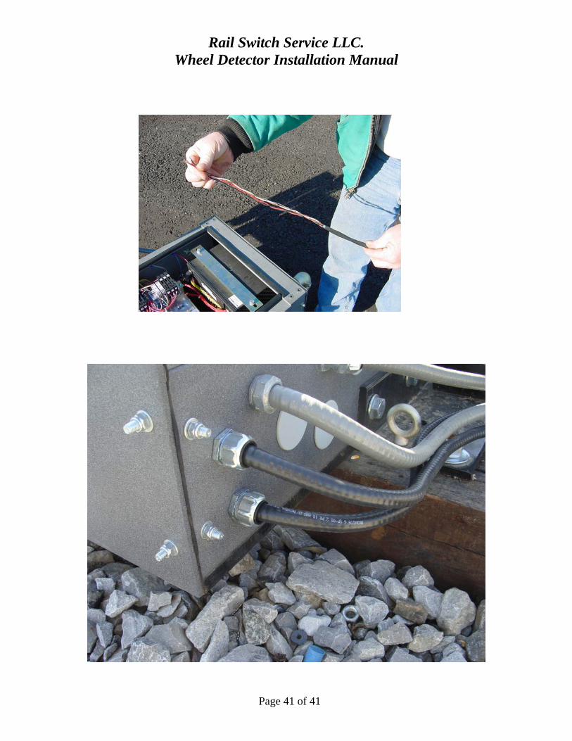
The power and communication cables are to be routed through the cord grips located on the trackside of the Switch Machine.
Note: the power and communication wires are all located within the same tray cable. This cable is an # 18 gauge 4-conductor direct burial cable with one conductor carrying B12, one conductor carrying N12 and the other two conductors acting as the signal transmission wires.
The power and communication cable should be stripped back 24" before inserting the cable through the cord grips. The cable should be pushed through the cord grips until the cable jacket is fully into the cord grip to assure a watertight entrance. Tighten the cord grips after installation of the cable.
Rail Switch Service LLC. Wheel Detector Installation Manual
Page 41 of 41

Rail Switch Service LLC. Wheel Detector Installation Manual
Page 42 of 42
The photo above shows two separate sensor cables entering the Switch Machine. One of the cables would be routed to the facing point wheel sensor/sensors. The other sensor cable would be routed to the trailing point wheel sensor/sensors.
Insert the white and black (pair 1) power wires and the white and black (pair 2) communication wires that make up the cable into the connector. This is done by pressing the wires into the spring cage connections. Tug on the wires to assure they are properly inserted in the spring cage.
Note removal of the wires requires pressing the small orange tabs down using a small screwdriver while pulling on the wire.
The correct terminal connections for the wires are as follows:
White wires, pair 2 = Terminals 15 & 16
Black wires, pair 2 = Terminals 13 & 14
White wires, pair 1 = Terminals 7 & 8
Black wires, pair 1 = Terminals 4 & 5
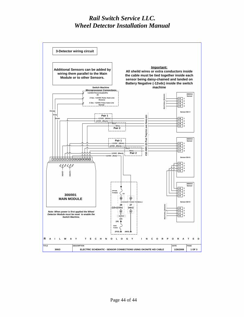
Please refer to RSS Wheel Sensor Schematic on page 43 for specific wire terminations.

Rail Switch Service LLC. Wheel Detector Installation Manual
Page 43 of 43
Rail Switch Service LLC. Wheel Detector Installation Manual
Page 44 of 44
1 2 3 4 5 6 7 8 9 10 11 12 13 14 15 16
300/001MAIN MODULE
4 5 6 7 8 9
-12V
DC
+1
2VD
C
TITLE
300/3
PAGE
1 OF 3
DATE
1/26/2008
DESCRIPTION
ELECTRIC SCHEMATIC - SENSOR CONNECTIONS USING OKONITE H/D CABLE
Note: When power is first applied the WheelDetector Module must be reset to enable the
Switch Machine.
R A I L W A Y T E C H N O L O G Y I N C O R P O R A T E D
3-Detector wiring circuit
Additional Sensors can be added bywiring them parallel to the Main
Module or to other Sensors.
1
1
2
2
3
3
4
4
300/015Sensor
1
1
2
2
3
3
4
4
300/015Sensor
1
1
2
2
3
3
4
4
300/015Sensor
(POS)
28(12V@10A)
27(NEG)
10A
OUTPUT
MAIN
FUSES
(28)
1A
OPTION
FUSE(S)
(NEG)
ACCESSORY POWER TERMINALS
White
Black
-12VDC (Black)
White
Black
+12VDC (White)
-12VDC (Black)
+12VDC (Red)
8
7
5
+12VDC\Throw Enable\Pin#8
.5 Sec. +12VDC Pulse Auto-LineReverse
.5 Sec. +12VDC Pulse Auto-LineNormal
Green
Gray
Orange
-12VDC (Black)
AD
DIT
ION
AL
SE
NS
OR
S
+12VDC (White)
#18
AW
G (
2) P
AIR
TW
IST
ED A
ND S
HIE
LD
ED
AD
DIT
ION
AL
SE
NS
OR
S
Sensor ID# 4
Sensor ID# 6
Sensor ID# 8
Pair 1
Pair 1
Pair 2
Pair 2
Switch Machine Microprocessor Connections
Important:All sheild wires or extra conductors insidethe cable must be tied together inside eachsensor being daisy-chained and landed onBattery Negative (-12vdc) inside the switch
machine

Rail Switch Service LLC. Wheel Detector Installation Manual
Page 45 of 45
Install the red ring terminals (included with the Wheel Detector System) on the shield ground wires. It is necessary to crimp the ring terminals on the shield ground wires, these are 1/4" ring terminals.
Attach the shield ground wire ring terminals to the N12 threaded lug located on the DIN rail terminal strip. This completes the installation and wiring phase of the Wheel Detector System.

Rail Switch Service LLC. Wheel Detector Installation Manual
Page 46 of 46
Power Up and Testing
When the installer is ready to power up the Wheel Detector System, it is necessary to close the Wheel Detector System fuse block. This will provide B12 (+12 VDC) power to the Wheel Detector System. Be certain there is no rail traffic in the protected zone or located over any of the wheel sensors when power is applied to the system. The wheel Detector System calibrates itself to the ambient conditions of the rail when power is first applied. The protected zone should be clear of all rail traffic in order for the system calibration to be accurate.

Rail Switch Service LLC. Wheel Detector Installation Manual
Page 47 of 47
After applying B12 (+12 VDC) power to the Wheel Detector System, the installer/user must press the red reset button on the side of the main module before the system will begin operation. IMPORTANT: The user should wait 5 seconds after power-up before pressing the reset pushbutton to allow the system time to calibrate to the ambient conditions around the wheel sensors. The reset pushbutton should be pressed in for a minimum of (2) seconds to assure the reset function has occurred.
This reset button must be pressed every time power is removed and re-applied to the Wheel Detector System before the system will enable the Switch Machine to operate and begin proper operation of the Wheel Detection System.
This reset button also resets the count in the zone to zero.

Rail Switch Service LLC. Wheel Detector Installation Manual
Page 48 of 48
The easiest way to test the Wheel Detection System is to use a railroad spike to “swipe” the wheel sensor. The spike must be held flat and must be swiped over the entire length of the sensor in the direction a train would travel to enter the protected zone to register a valid count on the sensor. This action simulates an axle entering the protected zone and will register a valid count thereby disabling the Switch Machine. This is indicated on the main module by the extinguishing of the # 1 LED.
Placing the spike over the sensor but not actually completing the swipe will disable the Switch Machine as long as the spike is located over the sensor. Removal of the spike will re-enable the Switch Machine. However, if the spike is swiped completely over the sensor, this will be recognized as an axle entering the zone and a count will be made disabling the Switch Machine until a swipe in the reverse direction occurs. A swipe in the reverse direction simulates the axle leaving the protected zone. When the count in the zone is zero the Switch Machine will be re-enabled. This is indicated on the main module by the illumination of the # 1 LED.

Rail Switch Service LLC. Wheel Detector Installation Manual
Page 49 of 49
Pressing the reset button on the main module will reset the count to zero and re-enable the Switch Machine at any time. Care must be exercised when performing this reset. If rail traffic is present in the protected zone when the reset is pressed, an incorrect count will result when the rail traffic leaves the zone and will disable the Switch Machine requiring yet another pressing of the reset button to re-zero the count.
This completes the installation and testing of the RTI Wheel Detection System. If there are any questions not answered in the context of this manual please contact the Factory for further assistance at the address or numbers below.
Rail Switch Service LLC. 1915 Lane Rd.
Paducah, KY. 42003 Ph: (270) 442-5090 Fax: (270) 444-9717