wheel balancer manual(cb800b) · sides for convenient operation. do not put the equipment a place...
TRANSCRIPT
0
Wheel Balancer Manual(CB800B)

1
Warning This manual is a necessary part of the product. Please read carefully. Keep the manual for later use when maintaining the machine. This machine can only be used for the designated purposes. Never use it for any other purpose. The manufacturer is not responsible for the damage incurred by improper use or use other than the
intended purpose.
Precaution
The equipment can only be operated by qualified personnel with special training. Modification to any components or parts, or use the machine for other purpose without either obtaining the agreement from the producer, or observing the requirement of the instructions may lead to direct or indirect damage to the equipment.
★ The equipment should be installed on the stable ground, not wooden pallet, otherwise not accurate. Keep the back panel 0.6M away from the wall for good ventilation. Enough room should be left on both
sides for convenient operation. Do not put the equipment a place with high temperature or moisture, or near the heating system, water tap,
air-humidifier or chimney. Avoid lots of dust, ammonia, alcohol, thinner or spraying binder. People who are no operating the machines should be kept away when it is used. Use appropriate equipment and tools, protective and safety equipment, including eyeglasses, earplugs and
working boots. Pay special attention to the marks on the machine. Do not touch or approach the moving parts by hand during operating. Do not remove the safety device or keep it from working properly.

2
Contents 1. General-----------------------------------------------------------------------------------------------------------------1 2. Machine assembly----------------------------------------------------------------------------------------------------1 3. Controls and components--------------------------------------------------------------------------------------------3 4. Indication and use of wheel balancer------------------------------------------------------------------------------6 5. Self-calibration of wheel balancer -----------------------------------------------------------------------------10 6. Errors------------------------------------------------------------------------------------------------------------------11 7. Self- diagnoses-------------------------------------------------------------------------------------------------------12 8. Setting machine------------------------------------------------------------------------------------------------------12 9. OPT function --------------------------------------------------------------------------------------------------------13 10. Spare parts list and Exploded drawings-------------------------------------------------------------------------15
1
1. General 1.1. Technical data:
Max wheel weight:65kg Power:0.2kw;0.37kw Power supply: 220v;230v;240v;110v;50hz;60hz Balancing accuracy:± 1g 8balancing modes: DYN, ALU1, ALU2, ALU3, ALU4, ALU5, ALUS, ST Balancing speed:200r/min Cycle time:8s Rim diameter:10〃~24〃(256mm~610mm) Sound pressure level during work cycle:<70db
1.2. Features: ALU balancing mode may choose 9 o’clock or 12 o’clock position to add weight Statistic and dynamic balancing, ALU-programs for alloy rims or special shaped Self diagnoses, easy to find the problem Apply to steel and aluminum alloy rim
1.3. Working environment: Temperature:5~50℃ Height:≤4000m
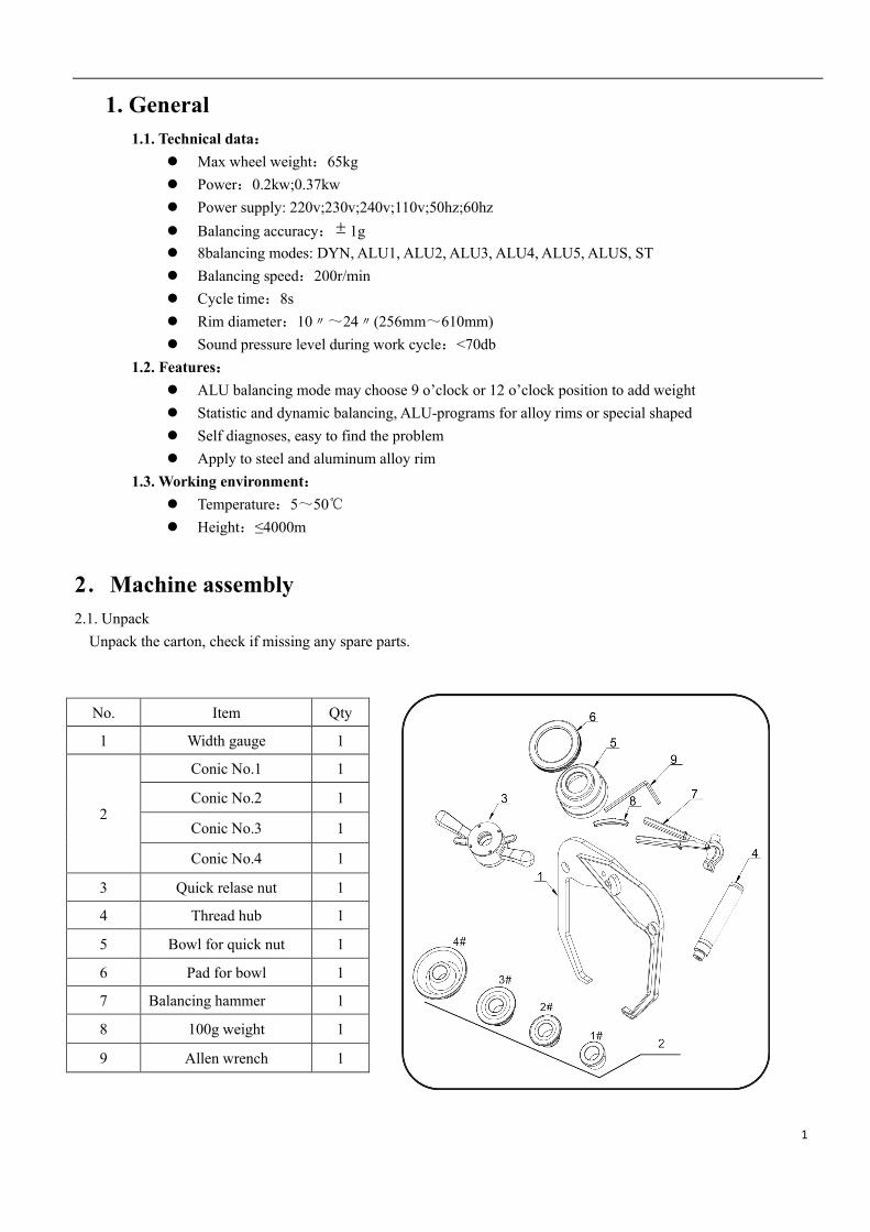
2.Machine assembly 2.1. Unpack
Unpack the carton, check if missing any spare parts.
No. Item Qty
1 Width gauge 1
2
Conic No.1 1
Conic No.2 1
Conic No.3 1
Conic No.4 1
3 Quick relase nut 1
4 Thread hub 1
5 Bowl for quick nut 1
6 Pad for bowl 1
7 Balancing hammer 1
8 100g weight 1
9 Allen wrench 1

2
2.2. Install
The equipment should be installed on the stable ground, not wooden pallet, otherwise not accurate. Keep the back panel 0.6M away from the wall for good ventilation. Enough room should be left on both
sides for convenient operation.
2.3. Fix balancer to floor with screws on the bottom. 2.4. Install adaptor The wheel balancer is supplied complete with cone type adaptor for fastening wheel with central bore. (see below picture)
2.5. Install wheel Clean wheel, take off counterweights, check pressure of wheel. Choose the way of installation according to the type of wheel.

3
Main shaft-wheel— Main shaft-suitable cone(big head towards inside)
suitable cone( small head towards inside)—quick handle nut —wheel—quick handle nut
Attention:May add a wheel, and hold the wheel to help install the thread hub. When installing or taking off wheel, do not let wheel move on the shaft, to avoid scratching shaft.
Display plate (G)
1.inside unbalance value digital display 2.inside unbalance position display 3.outside unbalance value digital display 4.outside unbalance position display 5.displays showing type of correction chosen. Eight balancing modes
Icon Balancing mode Operation Add weights
Standard/Default 1. Turn on machine 2. Input a,b,d value 3. Start spin, after spin stop
Clip on weights on both sides of rim edge
ALU1 1. Turn on machine 2. Input a,b,d value 3. Press ALU button, indicator lit up
Add adhesive weights on the rim shoulder
both sides

4
4. Start spin, after spin stop
ALU2
1. Turn on machine 2. Input a,b,d value 3. Press ALU button, indicator lit up 4. Start spin, after spin stop
Clip on weight on inside rim edge, add adhesive weight on outside rim shoulder
ALU3
1. Turn on machine 2. Input a,b,d value 3. Press ALU button, indicator lit up 4.Start spin, after spin stop
Add adhesive weights on the rim shoulder
both sides
ALU4
1. Turn on machine 2. Input a,b,d value 3. Press ALU button, indicator lit up 4. Start spin, after spin stop
Clip on weight on inside rim edge, add adhesive weight on
outside rim shoulder
ALU5
1. Turn on machine 2. Input a,b,d value 3. Press ALU button, indicator lit up 4. Start spin, after spin stop
Add adhesive weight on inside rim shoulder,
clip on weight on outside rim edge
ALUS
1. Turn on machine 2. Press ALU button, indicator lit up 3. Input aI,aE,d value 4. Start spin, after spin stop
Add adhesive weights on the two positions
gauge head touch
Static mode, for motorcycle
wheels
1. Turn on machine 2. Input a,b,d value 3. Press ALU button 4. Start spin, after spin stop
Add adhesive weight
Key board (H)
Icon Function Icon Function
Set distance
Optimization of unbalance
Set rim width
Selection of “ALU” modes
Set rim diameter
Static mode, for motorcycle wheels
5
Recalculation
Unbalance display pitch and threshold
Start
Stop/Cancel
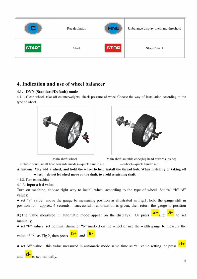
4. Indication and use of wheel balancer 4.1.DYN (Standard/Default) mode 4.1.1. Clean wheel, take off counterweights, check pressure of wheel.Choose the way of installation according to the type of wheel.
Main shaft-wheel— Main shaft-suitable cone(big head towards inside)
suitable cone( small head towards inside)—quick handle nut —wheel—quick handle nut Attention:May add a wheel, and hold the wheel to help install the thread hub. When installing or taking off
wheel, do not let wheel move on the shaft, to avoid scratching shaft. 4.1.2. Turn on machine 4.1.3. Input a b d value Turn on machine, choose right way to install wheel according to the type of wheel. Set “a” “b” “d” values: ● set “a” value:move the gauge to measuring position as illustrated as Fig.1, hold the gauge still in position for approx. 4 seconds, successful memorization is given, then return the gauge to position
0.(The value measured in automatic mode appear on the display). Or press and to set manually. ● set “b” value:set nominal diameter “b” marked on the wheel or use the width gauge to measure the
value of ”b” as Fig.2, then press and .
● set “d” value:this value measured in automatic mode same time as “a” value setting, or press
and to set manually.

6
Fig.1 Fig.2
4.1.4. Put down the guard and press to perform a measuring spin.
4.1.5. In a few seconds the wheel is brought to operating speed and begin measuring unbalance, the unbalance values
remain on instruments 1 and 3 when the wheel stopped. Press may check the real unbalance value under
threshold. 4.1.6. Anticlockwise moving wheel slowly, until the right LED lit up full, clip weight on 12 o’clock position (Fig.3)
Fig. 3 4.1.7.Anticlockwise moving wheel slowly, until the left LED lit up full, clip weight on 12 o’clock position (Fig.4)
Fig. 4
4.1.8. After finishing cliping the counterweights, put down the guard or press ,to perform balancing spin
again, if comes out 00 00,means balancing succeed. (Fig.5)

7
Fig. 5
4.2.ALU-1 mode (ALU-1, ALU2 same operation, only the position to add weights different) 4.2.1. Set “a” “d” “b” values
4.2.2. Press until ALU1 indicator lit up
4.2.3. Put down the guard and press to perform a measuring spin.
4.2.4. In a few seconds the wheel is brought to operating speed and begin measuring unbalance, the unbalance values
remain on instruments 1 and 3 when the wheel stopped. Press may check the real unbalance value under
threshold. 4.2.5. Anticlockwise moving wheel slowly, the displays with right LED’s lit up full indicate the correct angular position where to mount the counterweights, 12 o’clock position (9H=Off) or 9 o’clock (9H=On) position outside, as Fig.6, add the counterweight.
Fig. 6 4.2.6. Anticlockwise moving wheel slowly, the displays with left LED’s lit up full indicate the correct angular position where to mount the counterweights, 12 o’clock position (9H=Off) or 9 o’clock (9H=On) position inside, as Fig.7, add the counterweight.
Fig. 7
4.2.7. After finishing mounting the counterweights, put down the guard and press ,to perform balancing spin
again, if comes out 00 00,means balancing succeed. (Fig.8)

8
Fig. 8
4.3.ALU-S mode This mode is used for special rim, if ALU1/ALU2 can not be used, you should choose ALUS mode.
Input aI, aE, d value
Set “aI”: pull gauge out let the gauge head touch the position of FI for 4 seconds, may press and to change
Set “aE”: pull gauge out let the gauge head touch the position of FE for 4 seconds ,may press and . to change
Set “d”: read from rim, press and to input
Fig. 9
Put down the guard and press to perform a measuring spin.
4.3.1. 6 o’clock position to add weight Set SLC as OFF according to 8.1 4.3.2 Anticlockwise slowly turn the rim till all the right side unbalance indicators are lighting, At this moment, the outside rim at 6 o 'clock is the unbalance correction point. The correction of
surface for stick the weight is as shown in the figure below. Paste the weight on the positive plane
outside the spoke of the steel rim, as shown in (Fig.10)
Fig. 10 4.3.3 Anticlockwise slowly turn the rim till all the left side unbalance indicators are lighting, at this moment, the inside rim at 6 o 'clock is the unbalance correction point. The correction of surface
for stick the weight is as shown in the figure below. Paste the weight on the positive plane outside
the spoke of the steel rim, as shown in (Fig.11)

9
Fig. 11
After finishing mounting the counterweights, put down the guard and press ,to perform balancing spin again, if
comes out 00 00,means balancing succeed. (Fig.12)
Fig. 12
4.3.2. Use gauge head to add weight Set SLC as ON according to 8.1
Fig. 13
Anticlockwise moving wheel slowly, until the right LED lit up full (Fig.14)
Fig. 14
Take off proper counterweight to be hold by the gauge head as Fig. 16
Fig. 15 Fig. 16
Pull out gauge until there is a square comes in the middle window (Fig. 17)

10
Fig. 17
Release the counterweight and let it stick on rim (Fig. 18)
Fig. 18 Anticlockwise moving wheel slowly, until the left LED lit up full (Fig.19)
Fig. 19
Take off proper counterweight to be hold by the gauge head as Fig. 16 Pull out gauge until there is a square comes in the middle window (Fig. 20)
Fig. 20
Release the counterweight and let it stick on rim (Fig. 21)

11
Fig. 21
Then turn down safe guard and press to start spin, comes Fig. 22 means the wheel is balanced.
Fig. 22
4.ALUS split function Note: Only ALU-S mode can use this function. And Operator must be experienced.
Step 1
In the ALU-S mode, the results of the case, after the
comes>
Step 2
Through input wheel number, and then
press
comes>
Step 3
Keep any one of spoke on the position of 12 o’clock, press
comes>
Step 4
Anticlockwise rotate wheel by hand slowly, until the right SP1 LED lit up full, add the adhesive weight(to stick the
weights on position of 12 o’clock or 9 o’clock depends SLC=On or Off)
comes>
Step 5
Anticlockwise rotate wheel by hand slowly, until the outside SP1 lit right SP2 LED lit up full, add the adhesive weight(to stick the weights on position of 12 o’clock or 9
o’clock depends SLC=On or Off)
comes>
Step 6 Put down safe guard and press ,after spin stop comes>
Operation completed

12
5. Self-calibration of wheel balancer
5.1. Self-calibration of wheel balancer 5.2.Turn on balancer, install a medium size wheel (14″-18″)which can use clip-on weight, set “a b d” value, then
Do the self-calibration whenever you think the balancer is not accurate. The 100g weight must be accurate.
Step 1 Press and hold, then press comes
Step 2 Put down safe guard or press start spin, after spin stop comes
Step 3
Open the safe guard and clip a 100 gram weight on the outside
12 o’clock position, put down safe guard and press to
start spin, after spin stop
comes
Step 4
Open the safe guard and clip a 100 gram weight on the inside 12
o’clock position, put down safe guard and press to start
spin, after spin stop
comes
self-calibration finished
6.Rim distance gauge calibration
+ comes>
pull gauge to position “0” and hold, press comes>
pull gauge to position “15” and hold, press comes>
Rim distance gauge calibration finished
7. Rim diameter gauge calibration
Set “d” by press and , (for example if it is 14 inch, make it 14)
+ comes>

13
move gauge to touch the edge of rim and keep still
> Press
comes>
Rim diameter gauge calibration
8. Errors Various abnormal conditions can arise during machined operation by the microprocessor, if comes the errors, must stop operation, find the reason and the solution according, if the error persists, consult the supplier.
No. Errors Reasons Solution
1
1.No spin 2.Shaft spin
1.If no spin, check or change power board
2.If spin, check or change position pick up board and computer board
3. Adjust position pick up board support
2
1.No wheel or wheel not locked tightly
2.Position pick up board problem
1. Lock tightly 2. check or change position pick up board
3
1.No enough pressure in wheel 2.Wheel distortion
1.Add proper pressure in wheel 2.Check wheel
4
1.Position pick up board problem 2. Computer board problem
1.Check or change position pick up board 2.Check or change computer board
5
1. Micro switch problem 2. Computer board problem
1.Check or change Micro switch 2.Check or change computer board
6
1. Power board problem 2. Computer board problem
1.Check or change power board 2.Check or change computer board

14
7
1. Program lost 2. Computer board problem
1.Self calibration 2. Check or change computer board
8
1. No add 100g weight during self calibration 2.Computer board problem 3.Power board problem
1. Add 100g weight 2.Check or change computer board 3.Check or change power board
9
1.Micro switch problem 2. Computer board problem
1.Check or change micro switch 2.Check or change computer board
10
1.Computer board problem 2.Power board problem
1.Check or change computer board 2.Check or change Power board
9. Self- diagnoses
Press and hold, then press goest to self diagnoses, press to next , press to escape
Order Display Function Function normal
1
Display All lit up
2
Position pick up board POS changes in 0-127
3
Distance potentiometer Left window data is 327-340, when pull gauge out, the data changes
4
Diameter potentiometer left window data is 327-340, turn ruler to another direction, data changes
5
Width potentiometer(if provide)
left window data is 327-340, turn ruler to another direction, data changes
6
Pressure sensor Use hand to press main shaft, 4X-4X 6X-6X changes
10. Setting machine 10.1.Machine setting
Press and hold, then press goes to set machine, press and to change,press to next
Order Display function choice
1
Unbalance display threshold 5/10/15

15
2
Sound On/off
3
Light 1-8
4
Inch/mm inch on/inch off
5
9 o’clock position for adhesive weight
9 o’clock position/12 o’clock position
6
When ALU-S mode if use gauge head to add weight
OFF: is to stick weight at the 6'o
clock position (corresponding
position indicated by laser), ON:
is to stick weight on the pully
measurer head
7
Tire weight On/off
10.2 Safe guard setting
Press and hold, then press to set safe guard
Display Function Explain
Safe guard on Put down safe guard to start spin
Safe guard off Put down safe guard then press to start spin
10.3 Unit of weight setting
Press + to set safe guard
Display Function Explain
Unit of weight Gram
Unit of weight Ounce
11.OPT function Note: When unbalance value is too much, choose OPT, and operator must be experienced. Install wheel, input a b d value

16
1 Press comes>
2 Put down safe guard and press comes>
3 With the help of tire changer, change the rim and rubber 180 degree
reference>
>>
4 Then put down safe guard and press comes>
5
Rotate wheel until four indicators lit up (two on both sides, the dark spot in the right side picture), mark the positon C with chalk on rubber
reference>
6
Rotate wheel until two indicators lit up (one on both sides, the dark spot in the right side picture), mark the positon D with chalk on rim
reference>
7 With the help of tire changer, change the rim and rubber to make C and D match
reference>
>>
8 Put down safe guard and press comes> If unbalance is less than before, OPT succeed