wheatcrest solar project glint and glare assessment for
TRANSCRIPT

WHEATCREST SOLAR PROJECT
Glint and Glare Assessment for the Wheatcrest Solar Project BluEarth Renewables Inc.
Document No.: 10093992-HOU-R-03-B Issue: B Status: FINAL Date: 09 November 2020

DNV GL – Document No.: 10093992-HOU-R-03-B, Issue: B, Status: FINAL Page ii www.dnvgl.com
IMPORTANT NOTICE AND DISCLAIMER
1. This document is intended for the sole use of the Customer as detailed on the front page of this document to whom the document is addressed and who has entered into a written agreement with the DNV GL entity issuing this document (“DNV GL”). To the extent permitted by law, neither DNV GL nor any group company (the "Group") assumes any responsibility whether in contract, tort including without limitation negligence, or otherwise howsoever, to third parties (being persons other than the Customer), and no company in the Group other than DNV GL shall be liable for any loss or damage whatsoever suffered by virtue of any act, omission, or default (whether arising by negligence or otherwise) by DNV GL, the Group, or any of its or their servants, subcontractors, or agents. This document must be read in its entirety and is subject to any assumptions and qualifications expressed therein as well as in any other relevant communications in connection with it. This document may contain detailed technical data which is intended for use only by persons possessing requisite expertise in its subject matter.
2. This document is protected by copyright and may only be reproduced and circulated in accordance with the Document Classification and associated conditions stipulated or referred to in this document and/or in DNV GL’s written agreement with the Customer. No part of this document may be disclosed in any public offering memorandum, prospectus, or stock exchange listing, circular, or announcement without the express and prior written consent of DNV GL. A Document Classification permitting the Customer to redistribute this document shall not thereby imply that DNV GL has any liability to any recipient other than the Customer.
3. This document has been produced from information relating to dates and periods referred to in this document. This document does not imply that any information is not subject to change. Except and to the extent that checking or verification of information or data is expressly agreed within the written scope of its services, DNV GL shall not be responsible in any way in connection with erroneous information or data provided to it by the Customer or any third party, or for the effects of any such erroneous information or data whether or not contained or referred to in this document.
4. Any forecasts, estimates, or predictions made herein are as of the date of this document and are subject to change due to factors beyond the scope of work or beyond DNV GL’s control or knowledge. Nothing in this document is a guarantee or assurance of any particular condition or energy output.
KEY TO DOCUMENT CLASSIFICATION
Strictly Confidential : For disclosure only to named individuals within the Customer’s organization.
Private and Confidential : For disclosure only to individuals directly concerned with the subject matter of the document within the Customer’s organization.
Commercial in Confidence : Not to be disclosed outside the Customer’s organization.
DNV GL only : Not to be disclosed to non-DNV GL staff
Customer’s Discretion :
Distribution for information only at the discretion of the Customer (subject to the above Important Notice and Disclaimer and the terms of DNV GL’s written agreement with the Customer).
Published : Available for information only to the general public (subject to the above Important Notice and Disclaimer).

DNV GL – Document No.: 10093992-HOU-R-03-B, Issue: B, Status: FINAL Page iii www.dnvgl.com
Project Name: Wheatcrest Solar Project DNV GL - Energy
GL Garrad Hassan Canada, Inc. Bow Valley Square 4 250 – 6 Avenue SW Calgary, AB T2P 3H7
Report Title: Glint and Glare Assessment for the Wheatcrest Solar Project
Customer: BluEarth Renewables Inc. 400, 214 – 11 Avenue S.W. Calgary, AB T2R 0K1
Contact Person: Glenn Isaac Date of Issue: 09 November 2020 Project No.: 10093992 Document No.: 10093992-HOU-R-03-B Issue/Status: B/FINAL
Task and Objective: This report presents a glint and glare assessment conducted for the Wheatcrest Solar Project located within the Municipal District of Taber, Alberta. Prepared By: Verified By: Approved By:
Chelsea Scheske, B.Eng. Project Analyst
Ashley Rieseberg, M.Sc. Project Manager
Jeffrey Newmiller, M.Eng., B.Eng. Principal Engineer
☐ Strictly Confidential Keywords:
Glare; Solar; Alberta ☐ Private and Confidential ☐ Commercial in Confidence ☐ DNV GL only ☒ Customer’s Discretion ☐ Published © 2020 GL Garrad Hassan Canada, Inc. All rights reserved. Reference to part of this report which may lead to misinterpretation is not permissible. Issue Date Reason for Issue Prepared by Verified by Approved by A 23 October 2020 Draft C. Scheske A. Rieseberg J. Newmiller B 09 November 2020 Final C. Scheske A. Rieseberg J. Newmiller

DNV GL – Document No.: 10093992-HOU-R-03-B, Issue: B, Status: FINAL Page iv www.dnvgl.com
Table of Contents
EXECUTIVE SUMMARY ...................................................................................................................... VI
1 INTRODUCTION ............................................................................................................................. 1 1.1 Objective and Regulatory Context ................................................................................................. 1
2 PROJECT DESCRIPTION .................................................................................................................. 2
3 METHODOLOGY ............................................................................................................................. 4 3.1 Overview .................................................................................................................................... 4 3.2 Identification of Receptors ............................................................................................................ 5 3.3 Modelling Tool ............................................................................................................................. 7 3.4 Model Inputs, Assumptions, and Limitation ..................................................................................... 7 3.5 General Assumptions ................................................................................................................... 9
4 RESULTS AND ANALYSIS .............................................................................................................. 10 4.1 Summary ................................................................................................................................. 10 4.2 Impacts on Dwelling OPRs .......................................................................................................... 11 4.3 Impacts on Roads...................................................................................................................... 11 4.4 Impacts on Flight Paths .............................................................................................................. 13
5 CONCLUSION .............................................................................................................................. 14
6 REFERENCES ............................................................................................................................... 15
List of Figures Figure 1 - Project Layout and Receptor Map ......................................................................................... 3 Figure 2 - Ocular Hazard Plot.............................................................................................................. 5 Figure 3 - Illustration of Reflected Glare Impacting a Route .................................................................... 9
List of Tables Table 3-1 Project Observation Point Receptors and Route Point Receptors ................................................ 6 Table 3-2 Model Inputs Used for the Project ......................................................................................... 7 Table 4-1 Summary of Potential Glare Impacts for the Project .............................................................. 10 Table 4-2 Potential Glare Impacts on Project Dwelling OPRs ................................................................. 11 Table 4-3 Potential Glare Impacts on Project RPRs .............................................................................. 12 Table 4-4 Potential Glare Impacts on Project Intersection OPRs ............................................................ 13
Appendices
APPENDIX A – GLARE OCCURENCE PLOTS FOR ANALYZED OBSERVATION POINT RECEPTORS (OPRS)
List of Abbreviations
Abbreviation Meaning
ARC Anti-Reflective Coating
AUC Alberta Utilities Commission

DNV GL – Document No.: 10093992-HOU-R-03-B, Issue: B, Status: FINAL Page v www.dnvgl.com
ASL Above Sea Level
BMP Best Management Practice
DNV GL GL Garrad Hassan Canada, Inc.
km Kilometre
m Metre
MD Municipal District
MST Mountain Standard Time
OPR Observation Point Receptor
PV Photovoltaic
RPR Route Path Receptor

DNV GL – Document No.: 10093992-HOU-R-03-B, Issue: B, Status: FINAL Page vi www.dnvgl.com
EXECUTIVE SUMMARY
BluEarth Renewables Inc. (“BluEarth” or the “Proponent”) retained GL Garrad Hassan Canada, Inc. (“DNV GL”) to perform an independent glint and glare assessment for the proposed Wheatcrest Solar Project (the “Project”) which is located within the Municipal District of Taber, approximately 13 kilometres north of the Hamlet of Enchant.
DNV GL used the GlareGauge solar glare analysis tool to predict glare occurrence at observation point receptors and route path receptors selected within the vicinity of the Project and evaluate the associated ocular impacts on nearby dwellings, roads, and aviation activity. Glare predicted to occur at receptors was categorized into an ocular hazard colour code (green, yellow, or red) based on the intensity and angle of incoming light.
The results of this assessment show that glare associated with the Project will be limited to green and yellow glare that is minimal in daily duration and restricted to certain seasons and times of day. Based on the small duration of glare predicted at Project receptors and the fact that the route paths and intersections analyzed within the study are subject to minimal traffic, DNV GL is of the opinion that no further studies or mitigative actions are warranted for the Project to address glare impacts.

DNV GL – Document No.: 10093992-HOU-R-03-B, Issue: B, Status: FINAL Page 1 www.dnvgl.com
1 INTRODUCTION
BluEarth Renewables Inc. (“BluEarth” or the “Proponent”) retained GL Garrad Hassan Canada, Inc. (“DNV GL”) to perform an independent glint and glare assessment for the proposed Wheatcrest Solar Project (the “Project”) in order to identify the potential glint and glare impacts to dwellings, roads, and aviation activity located within the vicinity of the Project.
1.1 Objective and Regulatory Context
The objective of this glint and glare assessment is to fulfill the requirements stipulated by the Alberta Utilities Commission (AUC) within Bulletin 2019-09 – Interim Information Requirements for Solar and Wind Energy Plant Requirements (“AUC Bulletin 2019-09”)[1]. This bulletin states that applicants for new solar energy projects must include a solar glare assessment as part of the AUC Rule 007: Applications for Power Plants, Substations, Transmission Lines, Industrial System Designations and Hydro Development (“AUC Rule 007”) submission[1][2].
As per AUC Bulletin 2019-09, the solar assessment is required to include the following components:
• A description of the time, location, duration and intensity of solar glare predicted to be caused by the Project;
• A description of the potential impact upon dwellings and transportation routes surrounding the Project and any potential mitigation measures that are proposed; and
• A description of the software and tools used to complete the assessment, including any assumptions made[1].
In addition to the AUC Bulletin 2019-09 requirements, NAV CANADA also requires that a glint and glare study be submitted for solar projects as part of the Land Use Proposal submission. This was completed by BluEarth for the Project in November 2020.
At the time of writing this report, there are no other existing glint and glare requirements applicable to the Project.

DNV GL – Document No.: 10093992-HOU-R-03-B, Issue: B, Status: FINAL Page 2 www.dnvgl.com
2 PROJECT DESCRIPTION
The Project is located within the Municipal District (MD) of Taber, approximately 13 kilometres (km) north of the Hamlet of Enchant. The Project is situated on two adjoining quarter sections (SE-22-15-18-W4M and SW-22-15-18-W4M), encompassing 129.41 hectares (ha) of cultivated agricultural land (the “Project Area”). Elevation throughout the Project Area is relatively consistent with minimal variability, ranging from 802 m to 815 m Above Sea Level (ASL). Surrounding land use primarily consists of cultivated agricultural land and includes a small number of developed areas associated with residential properties and farming land uses. There are no airports or aerodromes located within four km of the Project area.
The Project will have a capacity of 60 megawatts and will consist of approximately 210,418 solar photovoltaic (PV) panels mounted on 27 degree fixed-tilt racking structures. Other Project components include internal access roads, underground collection lines, electrical inverters, a transformer substation, and a perimeter fence.
A map of the Project layout, including the dwellings and road features considered as part of this assessment, is included below (Figure 1).

DNV GL – Document No.: 10093992-HOU-R-03-B, Issue: B, Status: FINAL Page 3 www.dnvgl.com
Figure 1 - Project Layout and Receptor Map

DNV GL – Document No.: 10093992-HOU-R-03-B, Issue: B, Status: FINAL Page 4 www.dnvgl.com
3 METHODOLOGY
3.1 Overview
3.1.1 Definitions For the purposes of this assessment, DNV GL has relied on the following definitions used by the United States (US) Federal Aviation Administration’s (FAA) Technical Guidance for Evaluating Selected Solar Technologies on Airports for glint, glare, and reflectivity:
• Glint: A momentary flash of bright light reflected from a surface; and
• Glare: Continuous source of bright light reflected from a surface [3].
Glint is typically received by moving receptors (e.g. cars, airplanes) while glare is typically received by static receptors (e.g. dwellings). However, as industry-standard glare analysis tools, including the one used within this assessment (see Section 3.1), evaluate occurrence of glare on a minute-by-minute basis, ocular hazards are generally presented within glint and glare assessments using the collective term glare.
3.1.2 Reflectivity The amount of glint or glare that is reflected off a solar panel depends on wide variety of factors including the:
• Amount of sunlight that hits the panel surface;
• Overall reflectivity of the panel surface;
• Geographic location of the solar farm;
• Time of year;
• Cloud cover; and
• Orientation of the solar panel relative to the sun.
Solar PV panels are constructed of dark, light absorbing material that is designed to maximize sunlight absorption and minimize reflection in order to ensure maximum electricity production. The majority of solar PV panel glass covers are also treated with an anti-reflective coating (ARC) that further reduces the amount of sunlight that is reflected.
3.1.3 Ocular Impacts The standard practice for predicting potential ocular impacts is to calculate retinal irradiance and subtended angle (size/distance) of the glare source and based on the results, categorize the predicted ocular impact into one of the following three ocular hazard colour codes:
• Green: Glare with low potential to cause temporary after-image (i.e. lingering image in a viewer’s eye associated with a flash of light) to a viewer prior to a typical blink response time;

DNV GL – Document No.: 10093992-HOU-R-03-B, Issue: B, Status: FINAL Page 5 www.dnvgl.com
• Yellow: Glare with potential to cause temporary after-image to a viewer prior to a typical blink response time; and
• Red: Glare with potential to cause retinal damage to a viewer prior to a typical blink response time.
These widely accepted ocular hazard colour codes were originally established in 2011 by Ho et al. through a study that assessed the potential impacts of retinal irradiance as a function of subtended source angle. The ocular hazard plot contained within this study, included as Figure 2 below, was adopted by the FAA as part of their Interim Policy – FAA Review of Solar Energy Projects on Federally Obligated Polices as the standard for measuring the ocular impact of solar facilities [4][5].
Image, Ho et al. [4]
Figure 2 - Ocular Hazard Plot
3.2 Identification of Receptors
AUC Bulletin 2019-09 does not specify an assessment radius or maximum distance that should be used to identify potential receivers of glare. As a result, DNV GL used best practices to develop the following conservative approach to identifying Observation Point Receptors (OPRs) for the Project:
• Dwellings with potential to receive glare that are inhabited and located within 2,000 metres (m) of the Project Area;
• Routes and road intersections including driveways with potential to receive glare that are located within 1,500 m of the Project Area; and
• Aerodromes and associated flight paths with potential to receive glare that are located within 4,000 m of the Project Area.

DNV GL – Document No.: 10093992-HOU-R-03-B, Issue: B, Status: FINAL Page 6 www.dnvgl.com
To ensure a comprehensive analysis of potential glare for the Project, DNV GL included both routes and intersections as part of the glare assessment. Routes are denoted as Route Point Receptors (RPRs) and intersections are denoted as OPRs.
A summary of the receptors identified for the Project are presented in Table 3-1 below.
Table 3-1 Project Observation Point Receptors and Route Point Receptors
Receptor ID Receptor Type Details
OPR 1 Dwelling Potential Residence
OPR 2 Intersection Township Road 152 & Range Road 183
OPR 3 Intersection Township Road 152 & Range Road 182
OPR 4 Intersection Range Road 183 & Unidentified Rural Access Road
OPR 5 Intersection Range Road 183 & Driveway
OPR 6 Intersection Township Road 154 & Range Road 182
OPR 7 Intersection Township Road 154 & Range Road 183
OPR 8 Dwelling Potential Residence
OPR 9 Intersection Range Road 183 & Project Access Road
RPR 1 Route Range Road 182
RPR 2 Route Range Road 183
RPR 3 Route Township Road 152
RPR 4 Route Township Road 154
RPR 5 Route Unidentified Rural Service Road
3.2.1 Dwellings Two dwellings with potential to receive glare were identified within 2,000 m of the Project Area. One dwelling northeast of the Project Area was identified by DNV GL but excluded from analysis for two reasons: (1) the receptor is located north of the Project and as such, is unlikely to receive glare due to the south facing orientation of the panels, and (2) the receptor appears to be abandoned. The observation height at dwellings was assumed to be 4.5 m to align with the height parameters for two-storey dwellings stipulated within AUC’s Rule 012: Noise Control 15 [6]
3.2.2 Route Paths and Intersections Seven intersections and five route paths with potential to receive glare were identified within 1,500 m of the Project Area. To accurately capture glare received by various road users, three vehicle observation heights were used:

DNV GL – Document No.: 10093992-HOU-R-03-B, Issue: B, Status: FINAL Page 7 www.dnvgl.com
• Cars: 1.1 m;
• SUVs/Trucks: 1.8 m; and
• Semis/Tractors: 2.3 m [7].
3.2.3 Flight Paths No flight paths or aerodromes within 4,000 m of the Project Area were identified. The closest airport, Vauxhall Airport, is located more than 30 km from the Project Area [8]. As a result, assessment of potential Project impacts to flight paths and aerodromes was determined to not be necessary for the Project and these features were excluded from further analysis.
3.3 Modelling Tool
DNV GL used GlareGauge, a product of ForgeSolar, which is a comprehensive solar glare analysis tool that relies on Solar Glare Hazard Analysis Tool (SGHAT) technology developed by Sandia National Laboratories, to predict the potential for glare at OPRs and RPRs identified within the vicinity of the Project [9]. Assumptions and limitations associated with GlareGauge are described within Section 3.4.1.
3.4 Model Inputs, Assumptions, and Limitation
Table 3-2 below outlines the Project-specific parameters that DNV GL used as inputs for the model to complete the analysis, along with the default GlareGauge parameters.
Table 3-2 Model Inputs Used for the Project
Parameter Value Input Type
Axis Tracking None (Fixed tilt) Project-Specific
Panel Material Smooth glass without anti-reflective coating (ARC)
Project-Specific
Tilt 27 degrees Project-Specific
Ground Clearance 1.0 m Project-Specific
Orientation (Azimuth) 180 degrees (South) Project-Specific
Observation Heights
Dwelling 4.5 m Project-Specific
Car 1.1 m Project-Specific
SUV 1.8 m Project-Specific
Semi/Tractor 2.3 m Project-Specific
View Angle of Route Viewers 50 degrees left and right Default Value

DNV GL – Document No.: 10093992-HOU-R-03-B, Issue: B, Status: FINAL Page 8 www.dnvgl.com
Parameter Value Input Type
Analysis Time Interval One Minute Default Value
Reflectivity Varies with sun position Default Value
Ocular Transmission Coefficient 0.5 Default Value
Pupil Diameter 0.002 m Default Value
Eye Focal Length 0.017 m Default Value
Sun Subtended Angle 9.3 milliradians Default Value
Slope Error Correlates with material Default Value
3.4.1 Model Assumptions and Limitations Assumptions and limitations with the GlareGauge model are listed below:
• Times of day presented within the results (see Section 4) are denoted in Mountain Standard Time (MST). One hour should be added for daylight savings;
• GlareGauge requires a simplified version of a solar project as an input. Detailed geometry of the PV panels such as gaps between the modules is not represented within the algorithm used and as a result, actual glare results may be impacted. Despite this limitation, GlareGauge has been shown to accurately predict the occurrence and intensity of glare at multiple sites [9]. To mitigate this effect and obtain more accurate results, DNV GL separated the Project into seven distinct PV panel arrays and modelled each of these separately;
• Calculation of glare at path receptors (i.e. the RPRs) uses the PV panel array centroid, rather than the actual glare spot location, due to algorithm limitations;
• The algorithm used within GlareGauge assumes that the PV panel array is aligned with a plane defined by the heights and coordinates obtained from Google Maps;
• Potential screening from man-made or natural obstacles between the OPRs, RPRs, and the Project that may obstruct observed glare, such as vegetation or other physical obstructions are not accounted for within the model;
• The ocular hazard colours predicted are based on number of environmental, optical and human factors for which the model assumes a range of values. These factors will vary on a site and viewer-specific basis;
• The glare locations and glare vector plots presented on the glare occurrence plots (see Appendix A) are approximate and may differ from the actual glare spot locations and glare emanations; and
• The results of RPRs are based on a generic multi-line representation which simulates observers travelling along continuous paths. GlareGauge presents the results for RPRs in one-minute intervals. However, for the purposes of this study, these results should be interpreted from the point of view of the vehicle users, who will be traveling through the continuous glare zone relatively quickly,

DNV GL – Document No.: 10093992-HOU-R-03-B, Issue: B, Status: FINAL Page 9 www.dnvgl.com
resulting in momentary glint rather than continuous glare being observed at these locations (see Figure 3 below).
Image, ForgeSolar [9]
Figure 3 - Illustration of Reflected Glare Impacting a Route
3.5 General Assumptions
General assumptions made by DNV GL in completing the glare analysis are listed below:
• At the time that this report was written, the exact make and model of the PV panel has not been determined. Thus, DNV GL has conservatively used the maximum tilt angle (27 degrees) and assumed that the panel material would not have an anti-reflective coating (ARC) as this would produce the greatest reflectivity. However, DNV GL notes that the Project will be selecting a panel material with ARC;
• OPRs and RPRs were identified via aerial imagery and the receptors, access routes, and intersections included within this analysis were not field verified;
• Dwellings were assumed to be two-storey, with observation heights of 4.5 m [6]; and
• Observation heights for vehicles were assumed to be 1.1 m, 1.8 m and 2.3 m for cars, SUVs/trucks, and semis/tractors, respectively [7].

DNV GL – Document No.: 10093992-HOU-R-03-B, Issue: B, Status: FINAL Page 10 www.dnvgl.com
4 RESULTS AND ANALYSIS
4.1 Summary
The results of the analysis showed that no glare is predicted to occur at 8 of the 14 receptors. Furthermore, no red glare is anticipated for any of the six receptors where glare was predicted to occur.
A summary of results of the assessment are presented in Table 4-1 below and detailed glare results for the OPRs and RPRs are provided in Section 4.2 and Section 4.3 below.
Glare occurrence plots for receptors where glare was predicted are also provided in Appendix A. DNV GL notes that GlareGauge only produces glare occurrence plots for OPRs and RPRs where glare was predicted to occur and the specific PV panel array that the glare was reflected from.
Table 4-1 Summary of Potential Glare Impacts for the Project
Receptor ID
Receptor Type Maximum Green Glare (min/year)
Maximum Yellow Glare (min/year)
Maximum Red Glare (min/year)
OPR 1 Dwelling 0 0 0
OPR 2 Intersection 0 0 0
OPR 3 Intersection 0 0 0
OPR 4 Intersection 60 95 0
OPR 5 Intersection 0 0 0
OPR 6 Intersection 0 0 0
OPR 7 Intersection 0 0 0
OPR 8 Dwelling 25 0 0
OPR 9 Intersection 70 686 0
RPR 1 Route 0 77 0
RPR 2 Route 0 305 0
RPR 3 Route 0 0 0
RPR 4 Route 0 0 0
RPR 5 Route 0 255 0
DNV GL – Document No.: 10093992-HOU-R-03-B, Issue: B, Status: FINAL Page 11 www.dnvgl.com
4.2 Impacts on Dwelling OPRs
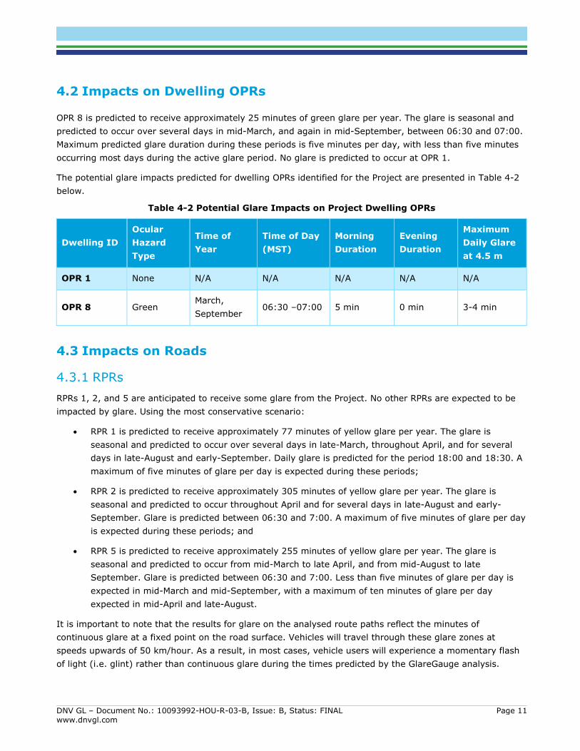
OPR 8 is predicted to receive approximately 25 minutes of green glare per year. The glare is seasonal and predicted to occur over several days in mid-March, and again in mid-September, between 06:30 and 07:00. Maximum predicted glare duration during these periods is five minutes per day, with less than five minutes occurring most days during the active glare period. No glare is predicted to occur at OPR 1.
The potential glare impacts predicted for dwelling OPRs identified for the Project are presented in Table 4-2 below.
Table 4-2 Potential Glare Impacts on Project Dwelling OPRs
Dwelling ID Ocular Hazard Type
Time of Year
Time of Day (MST)
Morning Duration
Evening Duration
Maximum Daily Glare at 4.5 m
OPR 1 None N/A N/A N/A N/A N/A
OPR 8 Green March, September
06:30 –07:00 5 min 0 min 3-4 min
4.3 Impacts on Roads
4.3.1 RPRs RPRs 1, 2, and 5 are anticipated to receive some glare from the Project. No other RPRs are expected to be impacted by glare. Using the most conservative scenario:
• RPR 1 is predicted to receive approximately 77 minutes of yellow glare per year. The glare is seasonal and predicted to occur over several days in late-March, throughout April, and for several days in late-August and early-September. Daily glare is predicted for the period 18:00 and 18:30. A maximum of five minutes of glare per day is expected during these periods;
• RPR 2 is predicted to receive approximately 305 minutes of yellow glare per year. The glare is seasonal and predicted to occur throughout April and for several days in late-August and early-September. Glare is predicted between 06:30 and 7:00. A maximum of five minutes of glare per day is expected during these periods; and
• RPR 5 is predicted to receive approximately 255 minutes of yellow glare per year. The glare is seasonal and predicted to occur from mid-March to late April, and from mid-August to late September. Glare is predicted between 06:30 and 7:00. Less than five minutes of glare per day is expected in mid-March and mid-September, with a maximum of ten minutes of glare per day expected in mid-April and late-August.
It is important to note that the results for glare on the analysed route paths reflect the minutes of continuous glare at a fixed point on the road surface. Vehicles will travel through these glare zones at speeds upwards of 50 km/hour. As a result, in most cases, vehicle users will experience a momentary flash of light (i.e. glint) rather than continuous glare during the times predicted by the GlareGauge analysis.

DNV GL – Document No.: 10093992-HOU-R-03-B, Issue: B, Status: FINAL Page 12 www.dnvgl.com
The potential glare impacts predicted for RPRs identified for the Project are presented in Table 4-3 below. To simulate potential glare experienced by a variety of road users, the results have been assessed for three vehicle observation heights: 1.1 m (cars), 1.8 m (SUVs/trucks), 2.3 m (semis/tractors).
Table 4-3 Potential Glare Impacts on Project RPRs
Route Path Receptor ID
Ocular Impact Category
Time of Year Time of Day (MST)
Maximum Daily Glare at 1.1 m
Maximum Daily Glare at 1.8 m
Maximum Daily Glare at 2.3 m
RPR 1 Yellow March, April, September
18:00 – 18:30 2 min 5 min 5 min
RPR 2 Yellow April, August, September
06:30 – 07:00 2 min 2 min 10 min
RPR 3 None N/A N/A N/A N/A N/A
RPR 4 None N/A N/A N/A N/A N/A
RPR 5 Yellow March, April, August, September
06:30 – 07:00 10 min 10 min 10 min
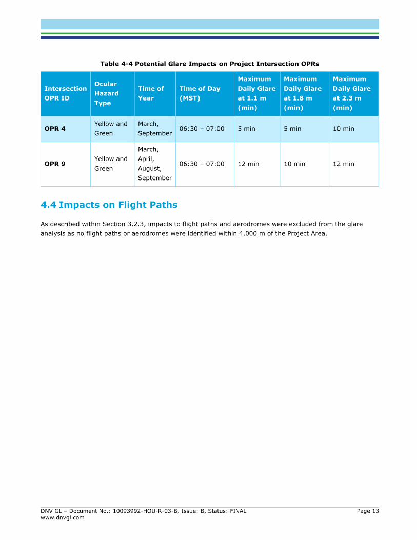
4.3.2 Intersection OPRs Only two intersection OPRs are expected to receive some glare from the Project. Using the most conservative scenario:
• OPR 4 is predicted to receive approximately 60 minutes of green glare per year and 95 minutes of yellow glare per year. The glare is seasonal and predicted to occur for several days in mid-March, and again in mid-September, between 06:30 and 07:00. Less than 10 minutes of glare per day is expected during these periods; and
• OPR 9 is predicted to receive approximately less than 70 minutes of green glare per year and 686 minutes of yellow glare per year. The glare is seasonal and predicted to occur from mid-March to late-April, and from mid-August to late-September, between 06:30 and 07:00. A maximum of 12 minutes of glare per day is expected during these periods.
The potential glare impacts predicted for intersection OPRs identified for the Project are presented in Table 4-4 below. The results have been calculated for three vehicle observation heights: 1.1 m (cars), 1.8 m (SUVs/trucks), 2.3 m (semis/tractors).
DNV GL – Document No.: 10093992-HOU-R-03-B, Issue: B, Status: FINAL Page 13 www.dnvgl.com
Table 4-4 Potential Glare Impacts on Project Intersection OPRs
Intersection OPR ID
Ocular Hazard Type
Time of Year
Time of Day (MST)
Maximum Daily Glare at 1.1 m (min)
Maximum Daily Glare at 1.8 m (min)
Maximum Daily Glare at 2.3 m (min)
OPR 4 Yellow and Green
March, September
06:30 – 07:00 5 min 5 min 10 min
OPR 9 Yellow and Green
March, April, August, September
06:30 – 07:00 12 min 10 min 12 min
4.4 Impacts on Flight Paths
As described within Section 3.2.3, impacts to flight paths and aerodromes were excluded from the glare analysis as no flight paths or aerodromes were identified within 4,000 m of the Project Area.

DNV GL – Document No.: 10093992-HOU-R-03-B, Issue: B, Status: FINAL Page 14 www.dnvgl.com
5 CONCLUSION
The results of this assessment show that glare associated with the Project will be limited to green and yellow glare that is minimal in daily duration and restricted to certain seasons and times of day. The most significant amount of glare predicted for the Project is at OPR 9, where a maximum daily glare duration of 12 minutes between 06:30 and 07:00 over several weeks in the spring and late summer is predicted to occur. It is important to note that the results presented within this report are considered to be conservative based on following rationale:
• DNV GL used the maximum tilt angle (27 degrees) and assumed that the panel material would not have an anti-reflective coating (ARC), as this would have the greatest reflectivity;
• The GlareGauge analysis tool does not consider potential screening by ground undulation, vegetation or existing structures; and
• Glare results at route path receptors, including OPR 9, are presented in one-minute intervals. These results do not suggest that a vehicle user will be exposed to continuous glare for these time periods. In reality, vehicle users will pass through these glare zones relatively quickly, so that the light will be experienced as a momentary glint, rather than continuous glare at these locations.
Thus, the amount of glare predicted at each of the reception points and routes and the associated ocular impacts are likely to be even less than what has been presented in this report.
Based on the small duration of glare predicted at Project receptors and the fact that the route paths and intersections analyzed within this study are subject to minimal traffic, DNV GL is of the opinion that no further studies or mitigative actions are warranted for the Project to address glare impacts. However, should residents or road users be concerned about the potential ocular impacts associated with the Project, measures such as installing blinds or vegetative screening, or utilizing a vehicle sun visor could be considered.

DNV GL – Document No.: 10093992-HOU-R-03-B, Issue: B, Status: FINAL Page 15 www.dnvgl.com
6 REFERENCES
[1] Alberta Utilities Commission, Bulletin 2019-09 – Interim Information Requirements for Solar and Wind Energy Plant Requirements, 3 July 2019.
[2] Alberta Utilities Commission, Rule 007: Applications for Power Plants, Substations, Transmission Lines, Industrial System Designations and Hydro Developments, 1 August 2019.
[3] Federal Aviation Administration, Technical Guidance for Evaluating Selected Solar Technologies on Airports, Version 1.1, April 2018.
[4] Ho, C. K., Ghanbari, C. M., and Diver, R. B., Methodology to Assess Potential Glint and Glare Hazards from Concentrating Solar Power Plants: Analytical Models and Experimental Validation, ASME J. Sol. Energy Eng., 133, 2011.
[5] Federal Aviation Administration, Interim Policy: FAA Review of Solar Energy Projects on Federally Obligated Airports, October 23, 2013.
[6] Alberta Utilities Commission, Rule 012: Noise Control, 2 March 2020.
[7] Alberta Transportation, Highway Geometric Design Guide – Chapter B, Alignment Elements, September 2020.
[8] NAV CANADA, NOTAM Series Aerodromes, 2015. Accessible from https://www.navcanada.ca/EN/products-and-services/Documents/AIP/Current/part_1_gen/excel/NOTAM_Series_Aerodromes.xltx
[9] ForgeSolar, Guidance and Information on Using ForgeSolar Analysis Tools, Undated, https://www.forgesolar.com/help/#glare.

DNV GL – Document No.: 10093992-HOU-R-03-B, Issue: B, Status: FINAL Page A-1 www.dnvgl.com
APPENDIX A – GLARE OCCURENCE PLOTS FOR ANALYZED OBSERVATION POINT RECEPTORS (OPRS)

DNV GL – Document No.: 10093992-HOU-R-03-B, Issue: B, Status: FINAL Page A-2 www.dnvgl.com
A.1 OPR 4
A.1.1 Vehicle Height: 1.1 m
Array 2

DNV GL – Document No.: 10093992-HOU-R-03-B, Issue: B, Status: FINAL Page A-3 www.dnvgl.com
Array 4

DNV GL – Document No.: 10093992-HOU-R-03-B, Issue: B, Status: FINAL Page A-4 www.dnvgl.com
A.1.2 Vehicle Height: 1.8 m
Array 2

DNV GL – Document No.: 10093992-HOU-R-03-B, Issue: B, Status: FINAL Page A-5 www.dnvgl.com
Array 4

DNV GL – Document No.: 10093992-HOU-R-03-B, Issue: B, Status: FINAL Page A-6 www.dnvgl.com
A.1.3 Vehicle Height: 2.3 m
Array 2

DNV GL – Document No.: 10093992-HOU-R-03-B, Issue: B, Status: FINAL Page A-7 www.dnvgl.com
Array 4

DNV GL – Document No.: 10093992-HOU-R-03-B, Issue: B, Status: FINAL Page A-8 www.dnvgl.com
A.2 OPR 8
A.2.1 Dwelling Height: 4.5 m
A.2.2 Array 2

DNV GL – Document No.: 10093992-HOU-R-03-B, Issue: B, Status: FINAL Page A-9 www.dnvgl.com
A.3 OPR 9
A.3.1 Vehicle Height: 1.1 m
Array 1

DNV GL – Document No.: 10093992-HOU-R-03-B, Issue: B, Status: FINAL Page A-10 www.dnvgl.com
Array 2

DNV GL – Document No.: 10093992-HOU-R-03-B, Issue: B, Status: FINAL Page A-11 www.dnvgl.com
Array 3

DNV GL – Document No.: 10093992-HOU-R-03-B, Issue: B, Status: FINAL Page A-12 www.dnvgl.com
Array 4

DNV GL – Document No.: 10093992-HOU-R-03-B, Issue: B, Status: FINAL Page A-13 www.dnvgl.com
Array 5

DNV GL – Document No.: 10093992-HOU-R-03-B, Issue: B, Status: FINAL Page A-14 www.dnvgl.com
A.3.2 Vehicle Height 1.8 m
Array 1

DNV GL – Document No.: 10093992-HOU-R-03-B, Issue: B, Status: FINAL Page A-15 www.dnvgl.com
Array 2

DNV GL – Document No.: 10093992-HOU-R-03-B, Issue: B, Status: FINAL Page A-16 www.dnvgl.com
Array 3

DNV GL – Document No.: 10093992-HOU-R-03-B, Issue: B, Status: FINAL Page A-17 www.dnvgl.com
Array 4

DNV GL – Document No.: 10093992-HOU-R-03-B, Issue: B, Status: FINAL Page A-18 www.dnvgl.com
Array 5

DNV GL – Document No.: 10093992-HOU-R-03-B, Issue: B, Status: FINAL Page A-19 www.dnvgl.com
A.3.3 Vehicle Height: 2.3 m
Array 1

DNV GL – Document No.: 10093992-HOU-R-03-B, Issue: B, Status: FINAL Page A-20 www.dnvgl.com
Array 2

DNV GL – Document No.: 10093992-HOU-R-03-B, Issue: B, Status: FINAL Page A-21 www.dnvgl.com
Array 3

DNV GL – Document No.: 10093992-HOU-R-03-B, Issue: B, Status: FINAL Page A-22 www.dnvgl.com
Array 4

DNV GL – Document No.: 10093992-HOU-R-03-B, Issue: B, Status: FINAL Page A-23 www.dnvgl.com
Array 5

DNV GL – Document No.: 10093992-HOU-R-03-B, Issue: B, Status: FINAL Page A-24 www.dnvgl.com
A.4 RPR 1
A.4.1 Vehicle Height 1.1 m
Array 5

DNV GL – Document No.: 10093992-HOU-R-03-B, Issue: B, Status: FINAL Page A-25 www.dnvgl.com
Array 7

DNV GL – Document No.: 10093992-HOU-R-03-B, Issue: B, Status: FINAL Page A-26 www.dnvgl.com
A.4.2 Vehicle Height: 1.8 m
Array 5

DNV GL – Document No.: 10093992-HOU-R-03-B, Issue: B, Status: FINAL Page A-27 www.dnvgl.com
Array 7

DNV GL – Document No.: 10093992-HOU-R-03-B, Issue: B, Status: FINAL Page A-28 www.dnvgl.com
A.4.3 Vehicle Height: 2.3 m
Array 5

DNV GL – Document No.: 10093992-HOU-R-03-B, Issue: B, Status: FINAL Page A-29 www.dnvgl.com
Array 7

DNV GL – Document No.: 10093992-HOU-R-03-B, Issue: B, Status: FINAL Page A-30 www.dnvgl.com
A.5 RPR 2
A.5.1 Vehicle Height: 1.1 m
Array 6

DNV GL – Document No.: 10093992-HOU-R-03-B, Issue: B, Status: FINAL Page A-31 www.dnvgl.com
Array 7

DNV GL – Document No.: 10093992-HOU-R-03-B, Issue: B, Status: FINAL Page A-32 www.dnvgl.com
A.5.2 Vehicle Height 1.8 m
Array 6

DNV GL – Document No.: 10093992-HOU-R-03-B, Issue: B, Status: FINAL Page A-33 www.dnvgl.com
Array 7

DNV GL – Document No.: 10093992-HOU-R-03-B, Issue: B, Status: FINAL Page A-34 www.dnvgl.com
A.5.3 Vehicle Height 2.3 m
Array 6

DNV GL – Document No.: 10093992-HOU-R-03-B, Issue: B, Status: FINAL Page A-35 www.dnvgl.com
Array 7

DNV GL – Document No.: 10093992-HOU-R-03-B, Issue: B, Status: FINAL Page A-36 www.dnvgl.com
A.6 RPR 5
A.6.1 Vehicle Height: 1.1 m
Array 4

DNV GL – Document No.: 10093992-HOU-R-03-B, Issue: B, Status: FINAL Page A-37 www.dnvgl.com
A.6.2 Vehicle Height: 1.8 m
Array 4

DNV GL – Document No.: 10093992-HOU-R-03-B, Issue: B, Status: FINAL Page A-38 www.dnvgl.com
A.6.3 Vehicle Height: 2.3 m
Array 4

DNV GL – Document No.: 10093992-HOU-R-03-B, Issue: B, Status: FINAL www.dnvgl.com
ABOUT DNV GL Driven by our purpose of safeguarding life, property and the environment, DNV GL enables organizations to advance the safety and sustainability of their business. We provide classification, technical assurance, software and independent expert advisory services to the maritime, oil & gas and energy industries. We also provide certification services to customers across a wide range of industries. Combining leading technical and operational expertise, risk methodology and in-depth industry knowledge, we empower our customers’ decisions and actions with trust and confidence. We continuously invest in research and collaborative innovation to provide customers and society with operational and technological foresight. Operating in more than 100 countries, our professionals are dedicated to helping customers make the world safer, smarter and greener.