what is securenet?
TRANSCRIPT

SECURENET SYSTEMS SECURENET CONCEPTS
What Is SECURENET?
Introduction Before we can begin our discussion of SECURENET equipment and systems,we must cover some ground work. We are going to begin with the basicbuilding blocks of SECURENET. If you are already familiar with. theseconcepts, then use this lecture and information for a review. If not, then usethem as a necessary learning tool.
Definition /Process
SECURENET is the most sophisticated digital voice encryption techniquecommercially available. The units that do the actual scrambling andunscrambling are configured to transmit and receive voice messages in eitherclear or coded mode, sometimes referred to as a dual-mode system.
The process of making a voice signal encrypted is accomplished in severalstages or operations. The first operation is to convert the analog audio to adigital signal. This is accomplished by a Continuously Variable Sloped DeltaModulator, more commonly referred to as a CVSD modulator, running at a12 KHz clock rate. This in turn gives a digital signal output at a 12 kilobit persecond rate.
Once the signal is in a digital format, the signal is then encoded or encryptedinto a “scrambled” digital signal. This output signal has a pseudo-randomdigital sequence. This means it has the characteristics of a random signal, butit also has a mathematical structure to it for proper decoding at the receivingend. This process of encrypting the signal uses a multi-register, non-linearcombiner algorithm set by a digital code or key.
After the signal is encrypted, it is filtered by a low pass filter to remove highfrequency harmonics. The filtered, scrambled signal is then applied to eithera modulator, for RF transmission, or a wireline, to be sent to a transmitter.If applied to a modulator the deviation should be adjusted to f4 Khz.
On the receive side the scrambled signal is recovered from the carrier by thediscriminator, like clear audio; or it is received down the wireline from areceiver. It is then applied to the circuitry for decoding.
The first step uses the received signal to synchronize the free-running 12 KHzclock. This operation is accomplished by the clock recovery circuit. Once theclock is synchronized, the “scrambled” signal goes through an amplifier/limitercircuit to reshape it into a squared 12 kilobit per second data stream. Notethat the signal is still scrambled upon the completion of this step, and thereshaped signal should resemble the one that left the encoder in thetransmitter.
9/01/92-MP
MOTOROLA National Service TrainingPage 1

SECURENET SYSTEMS SECURENET CONCEPTS
Next the “scrambled” digital signal is sent to the circuits where decoding isperformed. If the decoding circuit algorithms were set up with the same keyas the encoding circuit, the output will be an “unscrambled” 12 kilobit persecond digital signal. If the transmitter used a different key than the receiver,then the output will be a corrupted 12 kilobit signal that sounds like noise andis unusable.
The last step that’s needed to be done is to convert the 12 kilobit per seconddigital signal into analog audio. This process requires a CVSD demodulator,the CVSD demodulator in the receiver is configured to operate exactly inreverse compared to the CVSD modulator in the transmitter.
These are only a few facts of SECURENET and how it works. We will nowgo into greater detail of the “scrambling” process including how the CVSD andencryption circuits work. On the receive side, we will learn how the“descrambling” process takes place including clock synchronization and codedetection.
--
-
MOTOROLA National Service TrainingPage 2 s/o1 192-MP

SECURENET SYSTEMS SECURENET CONCEPTS
Transmit Secure Signal Flow
Introduction We are now going to discuss the process of converting audio to and from acoded signal. Once we get done with this section, you should be able to takethe knowledge gained and apply it to any SECURENET circuit, whether it isa CIU, portable or mobile radio.
First we are going to discuss what happens through the circuitry duringtransmit. We will talk about what happens with circuit operation whentransmitted coded and clear. Refer to fiere I.
E2EEOM
z,i’
./’ GENERATOR
/
ti‘-A/D CONVERTE PlAlN
e E N C O D E R r _:m SPLAlTERFILTER
A!& CLy!iD;Vd>lCE- L
1 PROCESSING I
DEVIATIONe\t
-- Fig. 1:
TO MoDulAmR
TRANSMIT SIGNAL FLOW
Coded/ClearMode Selection
The operator must select how he wants to transmit, clear or coded. Forargument’s sake we will say that the operator chooses to transmit a codedsignal. Once the selection has been made, the operator hits the Push-To-Talk(PTT) button. This will automatically switch the secure circuitry output to themodulator and disable the clear processing circuit’s output from going to themodulator. If the operator wants to transmit in the clear, he will select totransmit clear and depresses the PIT button. This time, however, the manualmode select block routes audio from the clear processing circuit to themodulator and disables the secure circuitry output to the modulator. The clearaudio goes directly from the microphone to the modulator. The clear audiois still going to the secure circuitry, but the switch disables the output.
12 KHz Clock This block is used to develop a 12 KHz clock that is used for timing,conversion processes and synchronization of the secure circuitry. The reasonfor using a frequency of 12 KHz is due to the analog to digital conversionprocess of the voice. This conversion process will be discussed later. Duringtransmit the 12 KHz clock will be locked, which provides for a stable clock.
B/O1 /92-MP
MOTOROLA National Service TrainingP&p 3

SECURENET SYSTEMS SECURENET CONCEPTS
CVSD The clear analog audio is going to be applied to the Continuously VariableSlope Delta (CVSD) modulator. The function of the CVSD modulator is to
-__. convert the analog audio to a digital signal.
In the SECURENET system, before the voice message can be encoded itmust be converted into a digital format. This digital signal output from theCVSD modulator is referred to as plain text. Plain means the signal is stillclear, and text means the signal is in a digital format. Likewise, at thereceiver, after being decoded, the digital signal must be converted back intoan analog voice format. These functions of analog-to-digital and digital-to-analog conversion are accomplished by the CVSD modulator/demodulator.
The CVSD modulation technique has been chosen for the SECURENETsystem because of several desirable system characteristics. It provides the bestpossible voice quality for the 12 kilobit rate used. Even though such a low bitrate is used, high intelligibility and good voice recognition are provided. Theserial digital output requires no frame synchronization; synchronization oftransmit and receive clocks is all that is needed. In addition, CVSD operationprovides a companding feature which makes the “talker-to-microphone”distances less critical. Finally, there is good tolerance to errors in thetransmission path, and no adjustments are required for proper operation.
---
In order to understand CVSD operation, it will help to have an understandingof Delta Modulation. Many of the principles of CVSD operation can beillustrated by first examining the basic Delta Modulator.
“Delta” means difference. When sampling voice signals there are someinherent qualities that we can take advantage of. Never will the amplitude ofa voice signal be quiescent from one sample period to another; meaning thatthe amplitude will continuously be either increasing or decreasing. In deltamodulation we will encode the difference in amplitude by generating “l’s” or“O’s”.
The delta modulator, figure 2, is basically a loop device which operates bycomparing the magnitude of the analog input signal at a specific point in timewith its magnitude at the previous sample time by means of an integratedfeedback signal. This feedback signal is subtracted from the input audio. Thisdifference signal is then converted into digital form by the limiter. The outputof the limiter is a digital “1” if the input audio is greater than thereconstructed audio and a digital “0” if the reverse is true. Obviously this is acomparison from the last voice sample.
MOTOROLA National Service TrainingPage 4 S/O1 /92_MP

SECURENET SYSTEMS SECURENET CONCEPTS
Fig. 2: DELTA MODULATION
In Delta Modulation, only the direction of the change is transmitted and nothow much of a change; therefore, the sampling rate has to be higher. Thesampling rate should be 8 times the highest expected frequency to bedigitized. The typical voice bandpass is up to 4 KHz, meaning that we wouldbe sampling at a 32 KHz rate. To sample at this speed would give us acomparable signal quality to that of the average telephone. There’s a problemwith this rate of sampling though. If you look at the output data rate of thistechnique, using a 32 KHz sample rate, it would be at 32 kilobits per second.32 kilobits per second would correlate to a highest fundamental frequency of16 KHz.
That’s 16 KHz before you even send it to a FM modulator to transmit overthe air. TOO much bandwidth...so what can we do to conserve bandwidth, andstill maintain an adequate voice quality? We’ll answer this question later.
If there is no audio input signal, the delta modulator will produce an outputcalled “idle pattern”. Here, at a particular clock sampling time, the integratorwill be above the input and thus the reclocking flip-flop output will be a “0”thereby causing the integrator to discharge. At the next clock time, theintegrator will have discharged so that it is below the input making the flip-flop output a “1” which will cause the integrator to charge. This process willcontinue until a voice signal occurs. The reconstructed audio will be a trianglewave and the digital output will be a squarewave both with a repetitionfrequency of l/2 the clocking frequency. In the SECURENET system, the idlepattern frequency is therefore 6 KHz due to a 12 KHz clock. The digitaldifference signal is then synchronized to the clock by passing it through areclocking, type D flip-flop. The output of this flip-flop is a digital,synchronized representation of the difference, or error, signal. It is this digitalsignal that is to be encoded.
B/O1 192~MPMOTOROLA National Sorvice Training
Page 6

ISECURENET SYSTEMS SECURENET CONCEPTS
The fact that the reconstructed audio can only change its slope at discretetimes and is limited to a choice of 2 slopes, one positive and one negative,means that the integrator output has been “quantized”. The integrator can notperfectly follow the input audio; this gives rise to a noiselike signal called“quantizing noise”. It can be reduced by increasing the sampling rate or byproviding more than 2 choices for the slopes.
A second important case to examine is called “slope overload”. Here theinput, a sine wave for example, is of such an amplitude and frequency that thereconstructed audio, since it can only change with a constant slope, cannotrise fast enough to track the input signal. The result is that the reconstructedaudio is no longer a good estimate of the input and severe distortion results.In this case, the distortion is evidenced by the amplitude of the reconstructedsignal being reduced.
-
Considering again a sine wave as the audio input, the fact that the inputfrequency is not synchronized to the clock frequency can cause dynamicamplitude variations called ‘beats.” For input frequencies at integer sub-multiples of the sampling clock, beats will not occur. This effect can be heardby sweeping the input signal and listening to the integrator output. In additionto the input frequency, a background tone will be heard that increases infrequency then decreases to a very low frequency at a clock sub-multiple, andthen increases, etc. Since beats are only heard when the input signal is tone-like and cannot be heard with a complex signal such as voice, they usually arenot a serious system problem.
Summarizing the above, there are 3 types of distortion to contend with in asimple delta modulator: 1) quantizing noise, 2) slope-overload, and 3) beats.Not much can be done to eliminate beats, but by adding additional circuitryto a delta modulator, the distortion caused by slope overload and quantizingnoise can be reduced. It was improved performance in these areas that led tothe selection of CVSD modulation for use in the SECURENET system.
The main problem with the basic delta modulator is that there are only 2choices for the integrator slope. If, when a large input is present, the slopecould be increased to track this signal, slope-overload characteristics could beimproved. By changing the slope to try to better match the input signal, thequantizing noise can also be reduced since the quantizing choices of thedemodulator are increased.
The signal required to control the variable slope can be formed by monitoringthe digital output of the delta modulator. If the output remains in one statefor several sampling periods, this is an indication that the delta modulatorcould be in slope-overload. By increasing the integrator slope gradually untilthere is no longer a given amount of consecutive “l’s” or “O’s”, it can beassured that the delta modulator will track the envelope of the input signaland not the instantaneous signal variations.
MOTOROLA National Service TrainingPage 6 B/O l/92-IMP

SECURENET SYSTEMS SECURENET CONCEPTS
The gradual increase or decrease of the integrator slope is why this form ofdelta modulation is called “continuously variable slope delta” modulation.Refer to Rgure 3.
Fig. 3: CVSD DIAGRAM
This gradual change in the slope control signal can be generated by filteringthe output of a consecutive “1” or “0” detector with a single section RClowpass filter with an appropriate cutoff frequency. By using the output of thisslope control filter to vary the amplitude of the digital signal applied to theintegrator, the slope of the integrator output will vary directly with the slopecontrol signal.
The variable slope filter shown in the block diagram is labeled a “syllabicfilter” because its cutoff frequency is set at 50 Hz to track the variations inenvelope amplitude as the various syllables of a word are spoken.
What this correlates to is a lower sample rate for the same voice quality. Thesample rate required to obtain the voice quality of a typical telephone is 16KHz. In SECURENET we have settled for slightly less than this in order tofurther conserve bandwidth. The sample frequency utilized in our CVSDprocess is 12 KHz. This computes to a data rate of 12 kilobits per second, anda highest fundamental frequency of 6 KHz.
9/o l/32-IMP
MOTOROLA National Service TrainingPage 7
SECURENET SYSTEMS SECURENET CONCEPTS
--
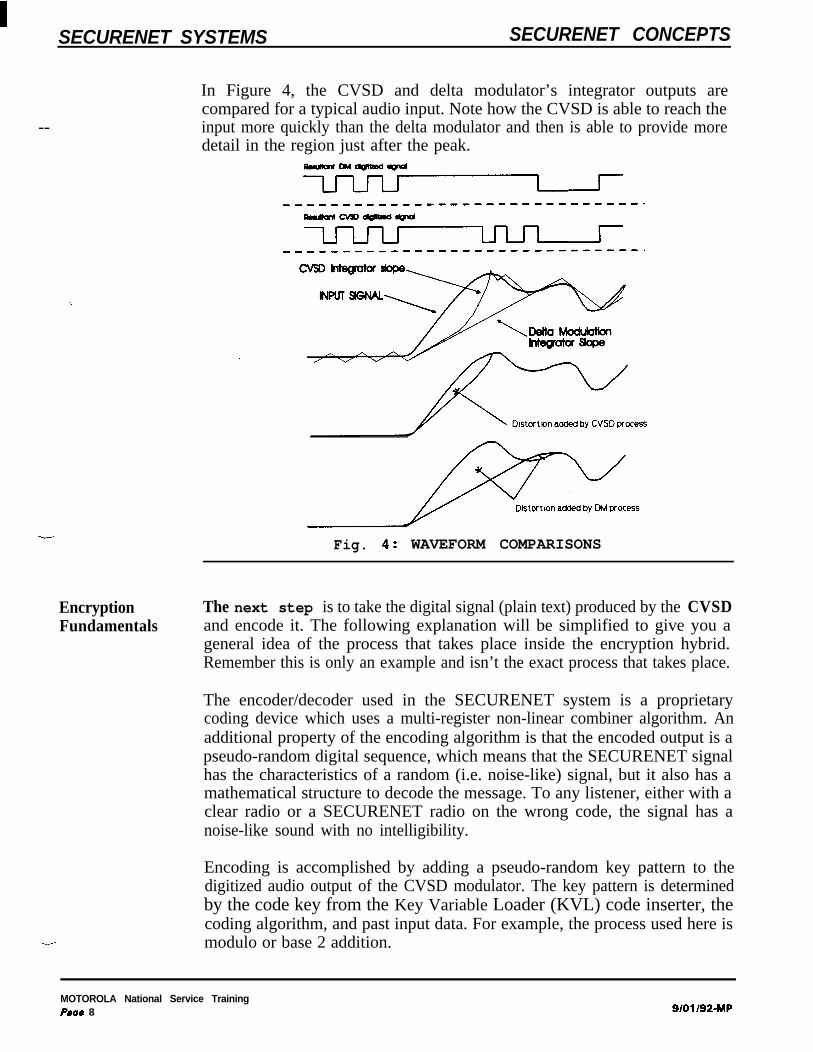
In Figure 4, the CVSD and delta modulator’s integrator outputs arecompared for a typical audio input. Note how the CVSD is able to reach theinput more quickly than the delta modulator and then is able to provide moredetail in the region just after the peak.
-w-W
--Fig. 4: WAVEFORM COMPARISONS
EncryptionFundamentals
The next step is to take the digital signal (plain text) produced by the CVSDand encode it. The following explanation will be simplified to give you ageneral idea of the process that takes place inside the encryption hybrid.Remember this is only an example and isn’t the exact process that takes place.
The encoder/decoder used in the SECURENET system is a proprietarycoding device which uses a multi-register non-linear combiner algorithm. Anadditional property of the encoding algorithm is that the encoded output is apseudo-random digital sequence, which means that the SECURENET signalhas the characteristics of a random (i.e. noise-like) signal, but it also has amathematical structure to decode the message. To any listener, either with aclear radio or a SECURENET radio on the wrong code, the signal has anoise-like sound with no intelligibility.
Encoding is accomplished by adding a pseudo-random key pattern to thedigitized audio output of the CVSD modulator. The key pattern is determinedby the code key from the Key Variable Loader (KVL) code inserter, thecoding algorithm, and past input data. For example, the process used here ismodulo or base 2 addition.
MOTOROLA National Service TrainingPme 8 a/oi/92-w
ISECURENET SYSTEMS SECURENET CONCEPTS
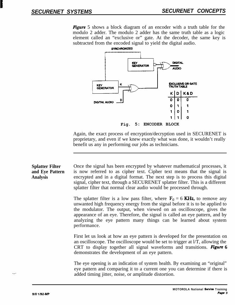
l%gure 5 shows a block diagram of an encoder with a truth table for themodulo 2 adder. The modulo 2 adder has the same truth table as a logicelement called an “exclusive or” gate. At the decoder, the same key issubtracted from the encoded signal to yield the digital audio.
SYNCHROMZEDc~~~~-~~~~~-~~~~~-----.Ii !Ii I
I 1
Fig. 5: ENCODER BLOCK
Again, the exact process of encryption/decryption used in SECURENET isproprietary, and even if we knew exactly what was done, it wouldn’t reallybenefit us any in performing our jobs as technicians.
Splatter Filterand Eye PatternAnalysis
Once the signal has been encrypted by whatever mathematical processes, itis now referred to as cipher text. Cipher text means that the signal isencrypted and in a digital format. The next step is to process this digitalsignal, cipher text, through a SECURENET splatter filter. This is a differentsplatter filter that normal clear audio would be processed through.
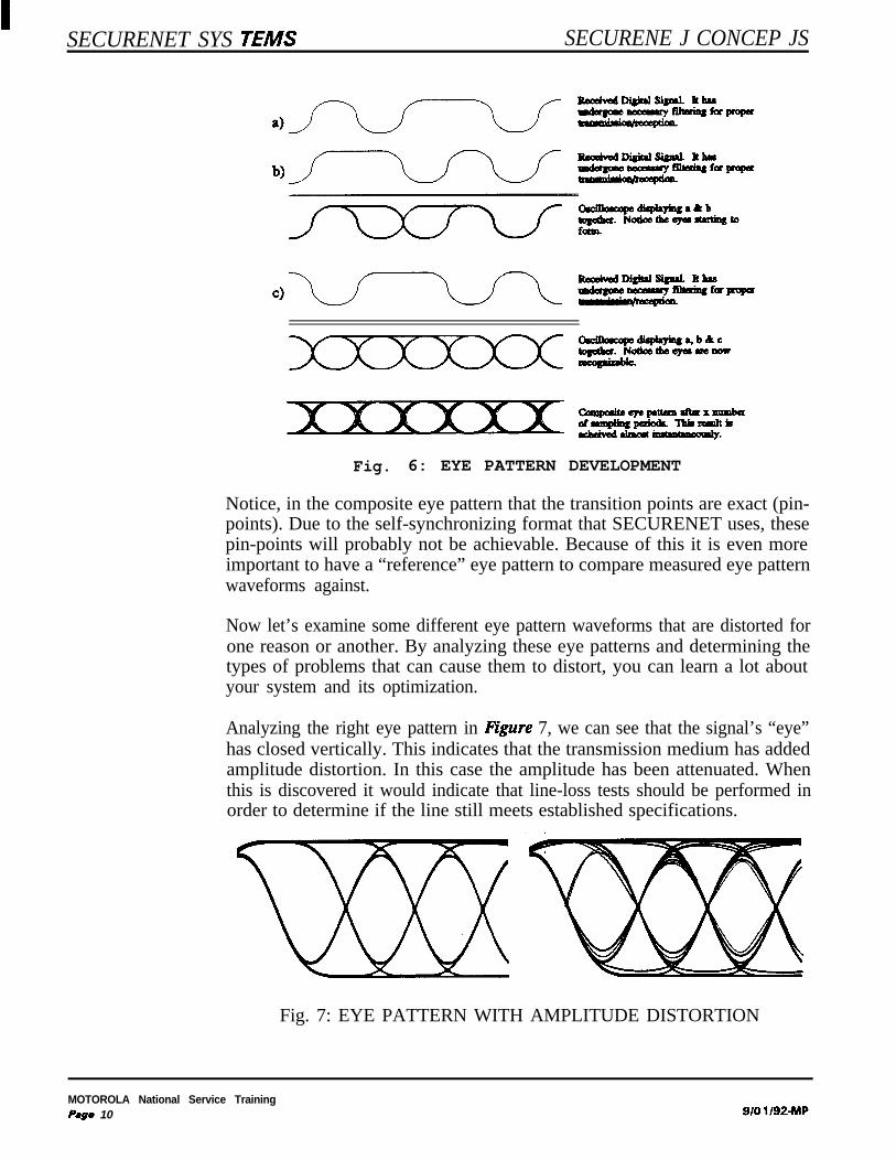
The splatter filter is a low pass filter, where Fc = 6 KHz, to remove anyunwanted high frequency energy from the signal before it is to be applied tothe modulator. The output, when viewed on an oscilloscope, gives theappearance of an eye. Therefore, the signal is called an eye pattern, and byanalyzing the eye pattern many things can be learned about systemperformance.
First let us look at how an eye pattern is developed for the presentation onan oscilloscope. The oscilloscope would be set to trigger at l/T, allowing theCRT to display together all signal waveforms and transitions. figure 6demonstrates the development of an eye pattern.
The eye opening is an indication of system health. By examining an “original”eye pattern and comparing it to a current one you can determine if there isadded timing jitter, noise, or amplitude distortion.
9/O l/92-MPMOTOROLA National Service Training
P8ge 9
SECURENET SYS JEMS SECURENE J CONCEP JS
Odbaxqedi#ayiqa,b&c
Fig. 6: EYE PATTERN DEVELOPMENT
Notice, in the composite eye pattern that the transition points are exact (pin-points). Due to the self-synchronizing format that SECURENET uses, thesepin-points will probably not be achievable. Because of this it is even moreimportant to have a “reference” eye pattern to compare measured eye patternwaveforms against.
Now let’s examine some different eye pattern waveforms that are distorted forone reason or another. By analyzing these eye patterns and determining thetypes of problems that can cause them to distort, you can learn a lot aboutyour system and its optimization.
Analyzing the right eye pattern in Egure 7, we can see that the signal’s “eye”has closed vertically. This indicates that the transmission medium has addedamplitude distortion. In this case the amplitude has been attenuated. Whenthis is discovered it would indicate that line-loss tests should be performed inorder to determine if the line still meets established specifications.
. .
Fig. 7: EYE PATTERN WITH AMPLITUDE DISTORTION
MOTOROLA National Service TrainingP.ge 10 9/o l/92-MP

SECURENET SYSTEMS SECURENET CONCEPTS
In figure 8, notice that the right “eye” in has closed horizontally. This is anindication that there may be timing jitter distortion problems. Once this hasbeen identified you may want to do a jitter unit interval test to determine ifthe transmission medium being used still meets specifications.
Fig. 8: EYE PATTERN WITH PHASE DISTORTION/JI’ITER
Comparing the patterns in figure 9, notice that the right signal, as comparedto the eye on the left, appears to be “fuzzy”. This would indicate noiseproblems, and gives an indication of both amplitude and phase distortion. Thistype of problem could render that link inoperable. A high-noise level wouldnecessitate investigation of all end-to-end equipment. Checks to perform mayinclude Idle-Channel-Noise (ICN), Noise-Power-Ratio (NPR), and grounding.
Fig. 9: EYE PATTERN WITH NOISE
All the forementioned situations could render that link/channel inoperable;they could also cause an increased bit error rate to occur.
DeviationAdjustment
The next step which occurs during transmit time is that the coded signal’sdeviation is set prior to being applied to the modulator, if in an RFtransmitting unit. Like the splatter filter circuit, there is a separate deviationadjustment for the coded signal and the clear signal. The deviation level ofthe coded signal should be set to +4 KHz, or as close to it as possible. If thedeviation level isn’t set properly, a degradation of your system may occur. Ifthe splatter filter is in a CIU, then there is no deviation adjustment. Thesignal is level adjusted and applied to the line outputs.
s/o1 192~MPMOTOROLA National Service Training
Page 77

SECURENET SYSTEMS SECURENET CONCEPTS
EOM
Transmit Clear Signal Flow
Process If the operator doesn’t choose to transmit in the coded mode, then all thisdiscussion is for naught. Referring back to Pipe 1, you can see that clearaudio will effectively bypass the SECURENET circuitry and go through clearprocessing circuits which consists partly of a separate splatter filter anddeviation adjustment. From there it is routed through the manual mode selectswitch and applied to the modulator or wirelines.
-
Lastly, as long as there is a P’IT, an eye pattern will be developed andtransmitted. Once the P’IT is released, the End Of Message (EOM)generation circuit develops an EOM. This is a 6 KHz clear sine wave burstat the end of transmission and will be discussed in more detail when coveringthe receive circuitry.
MOTOROLA National Service TrainingPage 12 a/01/92-rw
-
SECURENET SYSTEMS SECURENET CONCEPTS
Receive Coded Signal Flow
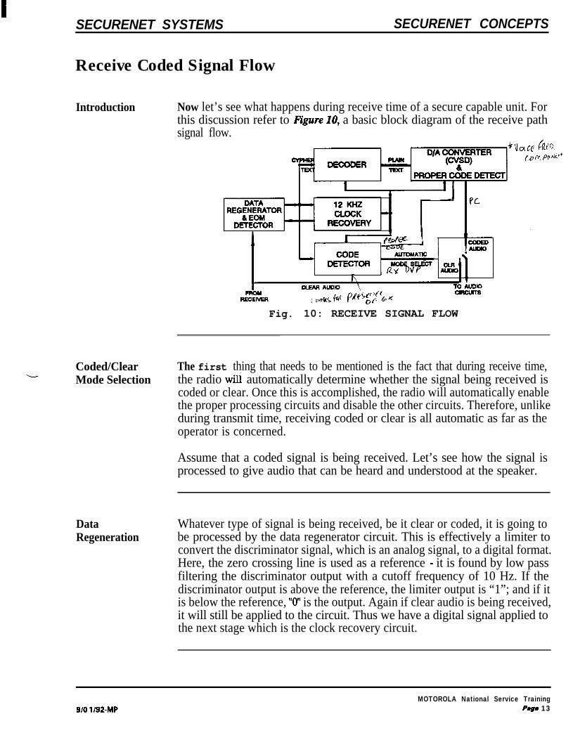
Introduction Now let’s see what happens during receive time of a secure capable unit. Forthis discussion refer to IQure IO, a basic block diagram of the receive pathsignal flow.
Fig. 10: RECEIVE SIGNAL FLOW
Coded/Clear The first thing that needs to be mentioned is the fact that during receive time,Mode Selection the radio wili automatically determine whether the signal being received is
coded or clear. Once this is accomplished, the radio will automatically enablethe proper processing circuits and disable the other circuits. Therefore, unlikeduring transmit time, receiving coded or clear is all automatic as far as theoperator is concerned.
Assume that a coded signal is being received. Let’s see how the signal isprocessed to give audio that can be heard and understood at the speaker.
DataRegeneration
Whatever type of signal is being received, be it clear or coded, it is going tobe processed by the data regenerator circuit. This is effectively a limiter toconvert the discriminator signal, which is an analog signal, to a digital format.Here, the zero crossing line is used as a reference - it is found by low passfiltering the discriminator output with a cutoff frequency of 10 Hz. If thediscriminator output is above the reference, the limiter output is “1”; and if itis below the reference, “0” is the output. Again if clear audio is being received,it will still be applied to the circuit. Thus we have a digital signal applied tothe next stage which is the clock recovery circuit.
9/o l/92-IMPMOTOROLA National Service Training
Pqp 13

ISECURENET SYSTEMS SECURENET CONCEPTS
I2 KHz Clock This circuit is going to synchronize its 12 KHz clock to the incoming signal soRecovery that the its clock is synchronized to the transmitting unit’s clock. Although the
.-- algorithm used by the decoder is self-synchronizing for recovery of the key, itdoes require that the receive clock be synchronized to the transmit clock. Itis the function of the clock recovery circuitry to do this, and in a manner suchthat the data can be recovered with minimum error. The clock recovery circuitmust not only synchronize to the transmit clock, but it must have the properphase relationship with the discriminator output. In the SECURENET system,these requirements are handled by using a digital Phase Lock Loop (PLL).
The digital phase lock algorithm uses the data transitions from the limiter tosample the recovered clock. Using the desired phase relationship betweenlimiter output and recovered clock, the following rules can be formed. If thedata transition occurs when the recovered clock is high, the clock is runningslow and should be speeded up. If the data transition occurs when the clockis low, the clock is running fast and should be slowed. If no data transitionsoccur, the clock is allowed to run at the nominal frequency - 12 KHz. Theaction of these rules is to have the receive clock position its negative goingedge on the data transitions. The pseudo-random nature of the encoded signalguarantees that there will be many data edges, thus providing manyopportunities to correct the receive clock. With the above rules, there cannever be a point at which corrections are not made (at a data transition); thismeans the receive clock will jitter about the correct value of clock phase. Thisjitter is minimized by using small increments to speed and slow the clock.
Once the clock has been adjusted, it is applied to the rest of the circuitry usedfor decoding the signal. In effect, all the SECURENET circuits on thereceiving unit are synchronized to the transmitting unit so proper decodingcan now take place.
Code Detection The next step is to determine whether the signal being received is clear orcoded. This process takes place in the code detect block. An importantoperational feature of the SECURENET system is its ability to automaticallydetermine whether a received message is in the clear or coded voice mode.All receivers in the SECURENET system have this feature.
This automatic coded/clear receive operation is made possible because of twoproperties of the SECURENET signal that differentiates it from clear voice,silent carrier or receiver noise: 1) the SECURENET signal is pseudo-randomand contains a significant number of “101” and “010” data sequences; and 2)the SECURENET signal always has level transitions that occur in some fixedtime relationship to one another as determined by the clock, i.e. the datatransitions are spaced apart by integer multiples of the clock period. Each ofthese conditions is necessary, but alone neither is sufficient to identify a codedmessage.
MOTOROLA National Service TrainingPage 14 a/o i /92-w
SECURENET SYSTEMS SECURENET CONCEPTS
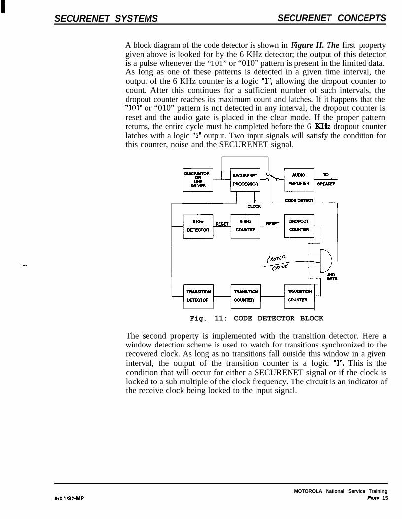
A block diagram of the code detector is shown in Figure II. The first propertygiven above is looked for by the 6 KHz detector; the output of this detectoris a pulse whenever the “101” or “010” pattern is present in the limited data.As long as one of these patterns is detected in a given time interval, theoutput of the 6 KHz counter is a logic “l”, allowing the dropout counter tocount. After this continues for a sufficient number of such intervals, thedropout counter reaches its maximum count and latches. If it happens that the“101” or “010” pattern is not detected in any interval, the dropout counter isreset and the audio gate is placed in the clear mode. If the proper patternreturns, the entire cycle must be completed before the 6 KHz dropout counterlatches with a logic “1” output. Two input signals will satisfy the condition forthis counter, noise and the SECURENET signal.
I I I r I
Fig. 11: CODE DETECTOR BLOCK
The second property is implemented with the transition detector. Here awindow detection scheme is used to watch for transitions synchronized to therecovered clock. As long as no transitions fall outside this window in a giveninterval, the output of the transition counter is a logic “1”. This is thecondition that will occur for either a SECURENET signal or if the clock islocked to a sub multiple of the clock frequency. The circuit is an indicator ofthe receive clock being locked to the input signal.
s/o l/92-MPMOTOROLA National Service Training
P#ge 15

--
SECURENET SYSTEMS SECURENET CONCEPTS
Decryption--“- Fundamentals
CVSD
The outputs of the two detectors are applied to a logic “AND” gate to give thecode detect output. TQbZe 1 gives the state from the code detector circuit forvarious input signal conditions. Once the code detector determines the typeof received signal, control signals will be generated to route that signal. Forany signal other than secure, the automatic mode select will bypass the securecircuitry and route the signal to the clear processing path.
INPUTTRANSlTlON SPEAKER
1 D;%T 1 DETECT 1 OUTPUT 1 OUT
NOISE 1~ 1 / 0 1 0 / SQUELCH
SILENT CARRIER / O / ’ 1 O / C%~~‘R
CLEAR VOICE / O I O / O 1 “v~~~~
CLEAR TONESUB MULT OF CLK /
CODED VOICE / ’ 1 ’ / ’ 1 DEVt6;)CDEED
Table 1: CODE DETECT TABLE
For a coded signal, the next step of the processing to be mentioned is to takethe signal, now in cipher text format, to the decoder hybrid. The decoder, nowproperly synchronized will do the exact opposite process that took place in thetransmitting unit. If the decoder hybrid was loaded with a different key as theencoder hybrid in the transmitting unit, the output from the hybrid will,effectively, be noise. However, if the decoder hybrid was loaded with the samekey as the encoder hybrid, the output will be a signal referred to as plain text.
Once the clear signal is recovered from the decoder hybrid, the next processis to convert the data signal to an analog signal. This uses a CVSDdemodulator, which does the exact opposite process discussed in the CVSDmodulator of the transmit section. With plain text input to the CVSDdemodulator, the output will be the decoded analog audio. Since the codedetector block already determined the signal was coded, the automatic modeselect switched to the coded audio path to route the decode audio to thespe’aker.
MOTOROLA National Service TrainingPage 16 B/O 1/92_MP

SECURENET SYSTEMS SECURENET CONCEPTS
EOM
-
Another function of the CVSD circuit during receive is to perform theoperation of “proper code detect.” Internal to the CVSD circuit there isanother correlation counter. This counter is looking for plain text. Of course,the only way the CVSD will receive plain text is if the same key was loadedin the encoder and decoder hybrids. If the keys were different, the outputfrom the decoder is noise. The proper code detector evaluates the signal todetermine whether it resembles noise. If the signal does resemble noise, a lowcorrelation count will be achieved, and this causes the speaker to stay muted.However, if the signal doesn’t resemble noise, plain text, a high correlationcount is achieved, and the speaker is unmuted. Proper code detect in a secureradio operates on the same principle as Private Line (PL) or Digital PrivateLine (DPL) in a standard radio. The speaker will not be unmuted until theproper signal is received.
Now the operator finally hears audio on the speaker. He didn’t have tophysically do anything to the radio to receive a clear or codedsignal. It was automatically accomplished by the circuitry.
The last topic to be discussed during receive time is EOM. It was stated thatwhen the operator released the P’IT, an EOM signal was generated andtransmitted. Now let’s see what the receiving unit does with the EOM.
One property of an encrypted message is the presence of significant 6 KHzcomponents at all time. As most FM receiver squelch circuits have beendesigned to view energy above 3 KHz to 4 KHz as noise, these squelchcircuits have a tendency to “block’ or mute coded signals. All secure radiosare therefore designed to bypass the receiver squelch circuit in the codedmode of operation, and use the code detector output to perform the squelchfunction.
As a result, however, squelch “tails” of considerable length can result at theend of coded messages. To eliminate these, an EOM scheme was developedwhich operates in a fashion similar to PL reverse burst. At the end of eachcoded message a burst of 6 KHz tone approximately 150 msec long istransmitted. Detection of this tone by any coded receiver resets the codedetector and mutes the audio. For clear messages, the operation of thereceiver squelch circuit and PL decoder, if present are unaffected. The netresult of this procedure is that in PL radios there are no squelch tails in eitherthe clear or coded mode, and in carrier squelch units, there are only squelchtails for clear mode operation.
9/o l/92-MPMOTOROLA National Service Training
P8ge 17

1SECURENET SYSTEMS SECURENET CONCEPTS
Algorithm Types
Introduction Now that we have an idea of what SECURENET is and a basic understandingof what takes place with the circuitry, we will discuss some of theSECURENET types, or more commonly, algorithms.
First, let’s define some acronyms used by Motorola. DW stands for DigitalVoice Protection, and DES stands for Data Encryption Standard. XL is thenomenclature used to identify an enhanced DVP/DES encryption algorithm.The enhancements and differences will be discussed later in the section. Fornow, know that none of the algorithms are compatible with each other. Table2 shows the features of the algorithms produced by Motorola and solddomestically.
DVP DVP-XL DES DES-XL
KEY FORMAT OCTAL HEX HEX HEX
if OF KEYS 2 3 x 10 *I 79x10~~ 7.2x1O16 7.2X10¹⁶
DUAL CODE 1 YES 1 NO / NO 1 No
NSA APPROVED 1 NO j NO / YES 1 YES
MOTOROLAPROPRIETARY
/ YES 1 YES j YES / YES
CODE RANGE =CLEAR RANGE / NO ( YES 1 NO / YES
Table 2: ALGORITHM FEATURES
Key Format The numbering system that the codes or keys of the different algorithms arewritten in is called the key format. For example, DVP is written in an octalformat (0 - 7), and all the others are written in hexadecimal format (0 - F).
# of Keys This field represents the number of different, unique keys available for aparticular algorithm. This number is determined mainly by the key format andthe number of entries per keys. Again as an example, with DVP written inoctal format and 24 entries per key, there will be the approximate number ofkeys indicated in Table 1.
MOTOROLA National Service TrainingPege 18 9/01/924ulP

SECURENET SYSTEMS SECURENET CONCEPTS
Dual Code
NSA ApprovedAlgorithms
Motorola Notice that all the algorithms are Motorola proprietary. Information about theProprietary exact mathematical processes that take place can’t be discussed.
Coded Range =Clear Range
Normally, an algorithm is capable of holding only one key at a time. Dualcode is the ability of the algorithm to develop a 2ND, unrelated code from thefirst code. You’ll notice that DVP is the only algorithm capable of dual code.The one thing to remember with DVP and dual code is that a radio using theoriginal code isn’t capable of communicating with another radio using the 2NDderived code.
NSA is an acronym for National Security Agency. These algorithms must meetsecurity specifications written and approved by the NSA. If they don’t, thenthe algorithm can’t be sold to other U.S. government agencies. The NSAspecifications are the same for a competitor as well, but again Motorola’salgorithms aren’t compatible with the competitor’s.
The last line of the Table 1 shows one of the differences between non-XL andXL algorithms. Later, we will discuss a couple of more differences. A non-XLsystem will have some range loss in the coded mode verses the clear mode.However, with the enhanced XL version, the coded range is approximately thesame as the clear range.
g/01/92-MPMOTOROLA National Serviw Training
Page 79

ISECURENET SYSTEMS SECURENET CONCEPTS
Differences Between Non-XL And XL-_.___ -
Introduction This of the discussion will cover differences between non-XL and XLalgorithms. We will discuss differences in synchronization methods, Bit ErrorRate (BER), and more on range differences of coded verses clear.
SynchronizationMethods
The first difference between algorithms concerns synchronization methodsused in the SECURENET receive circuitry, Figure 12. A non-XL type ofencryption, sometimes referred to as cipher feedback, uses a method calledself-synchronization to synchronize the receive 12 KHz clock. As shown by thetop half, the trailing edge of the 12 KHz will fall at or near every transitionof the incoming data. If the trailing edge of the clock doesn’t fall at the sametime as a transition of data, the clock recovery circuits will either slow orspeed up the clock to coincide with the falling transition of data. Theincoming encrypted data actually synchronizes the clock.
The bottom half is a representation of how an XL type of encryption,sometimes referred to as counter addressing, synchronizes the data. Noticethat with XL the signal is preceded with a preamble. This performs a similarfunction as High Level Guard Tone (HLGT) to a station. Once the preambleis received, sync bits are inserted into the data stream, and these sync bits areused to synchronize the clock, instead of the data synchronizing the clock.
At the end of either transmissions EOM is sent by the transmitting unit.When the receiving unit detects the EOM, which is a clear 6 KHz sine wave,it will mute the speaker before the loss of the received carrier. This willprevent a noise burst, “squelch tail”, from being heard at the speaker. EOMoperates on the same principle as PL reverse burst or DPL EOM tone.
- DATA NoaJcmNCSYNCSCLK ausEsLoI#
; ; I !
i ii i
iiI I
EK0 II I
t I i j* .DVP/DES
SELF-SYNCHRONIZING
12: SYNCHRONIZATION METHODS
MOTOROLA National Service TrainingPage 20 a/o1 192-w

SECURENET SYSTEMS SECURENET CONCEPTS
-
BER The second difference between the two encryption types is Bit Error Rate(BER). The first thing that needs to be discussed about BER is, what is BER?Bit error rate is defined as the percentage of mistakes made by the receivingunits digital regeneration circuits due to signal degradation.
Any time a message is transmitted from one unit to another by any means, acertain amount of degradation occurs. This degradation is caused by manyfactors which may be generalized into three main categories: 1) the additionof noise to the signal; 2) limitations in the bandwidth of the equipment or thetransmission medium; and 3) phase non-linearities in the equipment or path.In any analog transmission scheme, including clear voice transmission, thereis little which can be done to eliminate most of this degradation once itoccurs. Rather the emphasis is placed on trying to prevent the degradationfrom occurring in the first place, hence such concentrated efforts to obtainhigh selectivity and intermodulation rejection specifications (to eliminatemuch of the noise interference by filtering) and close attention to frequencyresponse and harmonic distortion.
When a digital message is transmitted it is subject to the same interferencesand distortion, but due to the nature of such a signal many of the standardapproaches of dealing with such problems do not apply. Within broad limits,for example, concerns with frequency response and distortion really doesn’tapply in the same manner. While an analog signal can’t be *‘cleaned up” oncedegraded, a digital signal can be “cleaned up” to a great extent if it istransmitted synchronously. This “clean up” or regeneration consists of limitingthe incoming signal to eliminate any noise component which has been addedto it, and reclocking it to eliminate any jitter acquired due to system phasenon-linearities.
The application of this digital regeneration technique to thetransmission ofdigital voice messages (as in DVP and DES) causes an effect which is notcommon in normal radio applications. With conventional FM radio systems,the quality of a received signal slowly degrades as the signal strength dropsuntil eventually the signal-to- noise ratio is so poor that communicationceases. With a digital voice system, the received signal quality is constant asthe signal strength drops until it reaches the point where the noise componentis so strong that the regeneration circuitry can no longer reconstruct thesignal, at which point communications cease. This “cliff’ effect makesconventional sensitivity measurements misleading, as 20 dBq and 12 dBSINAD are already below the “knee” of the performance curve, and aretherefore not desirable operating points.
To derive a useful measure of coded mode receiver sensitivity, a new concept(to voice communications) must be introduced, known as the “Bit Error Rate”.Bit errors are caused by the digital regeneration circuitry making a mistakein recovering the received signal, due either to excessive noise or phase jitteror to bandpass limitations rolling off too much of the amplitude of the signal.
s/o1 /92-MPMOTOROLA National Service Training
Page 2 1

SECURENET SYSTEMS SECURENET CONCEPTS
--
RangeDifferences
.Y’
The bit error rate is a measurement of how many bit errors occur in a fixedsample period, usually of 1000 bits or more, expressed as a percentage. Thereare two distinct types of error rates which are encountered in DVP/DESequipment: 1) the channel error rate and 2) the decoded error rate. Thechannel error rate is the measure of how many mistakes the regenerationcircuitry is making due to imperfections in the transmission path itself. Eachbit interpreted incorrectly here is one bit error. Due to the errormultiplication property of the DVP/DES decoder, the decoded bit error ratewill be considerably higher as this is a measure of the number of wrong bitsgoing into the CVSD. In practice, channel errors are extremely difficult tomeasure, so in all subsequent discussion “bit error rate” should be taken tomean decoded bit error rate. Coded mode receiver specifications arereferenced to 5% bit error rate, which occurs just about the knee of the “cliff’mentioned before.
Figure 13 gives a simplified diagram of the Bit Error Rate differencesbetween non-XL and XL. Notice in a non-XL system, which is represented inthe top half of I3gure 13, 1 channel error in will be multiplied by a factor of32 through the decoder to give 32 decoded errors on the output. In an XLsystem, shown in the bottom half of Figure 13, 1 channel error in will bemultiplied by a factor of 1 through the decoder to give 1 decoded error out.These multiplication factors for non-XL and XL circuitry are due mainly bythe synchronization method used in the decoding process mentioned earlier.
Fig. 13: BER DIFFERENCES
1’
The last topic to be discussed between non-XL and XL concerns differencesin coded range as compared to clear range for audio coverage purposes.figure 14 gives a pictorial representation of clear ranges, coded ranges whenusing a non-XL system, and coded ranges when using an XL system. Pleasenote that these ranges are approximations and depending on your particularsystem configuration and optimization, the actual coverage will probably vary.
MOTOROLA National Service TrainingPage 22 B/O l/92-MP

SECURENET SYSTEMS SECURENET CONCEPTS
Fig. 14: RANGE DIFFERENCES
In the example, the normal clear range for intelligible audio on the receivingunit’s speaker is 100 miles. The non-XL coded audio effective range is about70 miles. Thus with a non-XL system is use, the effective coverage area isreduced by approximately 30% as compared to clear coverage.
---The XL coded audio effective range, however, is about 98 miles. Therefore,with an XL system in operation, the effective coverage is more like clearaudio coverage. In this example, the coverage area is approximately 98% thatof clear audio coverage.
The reasons for better coverage in an XL system are due mainly to the otherdifferences that were previously discussed: synchronization methods and themultiplication factor with the bit error rate. For some applications a non-XLsystem will operate with little or no degradation to communications, but inother systems XL may be necessary, such as in trunked system.
--
s/o1 /92-MPMOTOROLA National Service Training
Page 23

ISECURENET SYSTEMS SECURENET CONCEPTS
Basic SECURENET Systems
--
Introduction Now that there is an understanding of what SECURENET is, the differenttypes of algorithms, and the differences between non-XL and XL, we areready to graduate to the next level of learning. We are going to discuss somebasic, generic SECURENET systems. These will be discussed on a block levelto get you familiar with components and operation of some typical systems.
Encode/DecodeSystem
The first system is a basic encode / decode system. In an encode/decodesystem, the encryption key is stored in the base station, mobile and portableradios. The required equipments for this system are a console, encode /decode base station, encode / decode mobile and portable radios. The factthat the base station is canable of encodinp and decoding the actual siPna1. iswhere the name for this particular svstem is derived.
Let’s take a signal through the system from the console to the subscriberunits. Please refer to figure 15 for the following discussion on the system.
:::... . . . . .:3
SECURE 111
I
VOICE GRADE
TONE REMOTETELEPHONE LINE ENCODE
DECODE
CONSOLE BASENONSECUREIII STATlON
L I 1
Fig. 15: ENCODE/DECODE SYSTEM
Transmitting of a clear or coded signalis manually selected by the initiatingunit, in this case the dispatcher. If the dispatcher selects to transmit codedaudio, the tones and voice will travel down normal voice grade telephone lineif the station is remotely located. The tones will inform the station to encodethe audio before sending it to the modulator. The audio is encoded internallyin the base station, sent to the modulator, and transmitted out into the airwaves as a “scrambled” signal.
MOTOROLA National Service TrainingPage 24 a/oi/92-w

SECURENET SYSTEMS SECURENET CONCEPTS
The subscriber units receive the RF, discriminate the signal to recover theintelligence, and decode the signal before sending the audio to the speaker.If the subscriber units are loaded with the same key as the station, then thesubscriber operator will hear the audio. If a different key is in the subscriberunit than the station, the operator will hear noise or nothing if proper codedetect function is used.
For clear transmission from base station to subscriber unit, the only differenceis that the dispatcher selects to transmit in the clear mode. Next the consolewill now send tones to inform the station not to encode the incoming audio.Clear audio is now sent down the phone lines to the transmitter and over theair.
The exact opposite operation takes place when the subscriber unit wants totalk back to the dispatcher. The mobile or portable radio now converts theclear audio to a “scrambled“ signal. Once again the operator of the subscriberunit has to select to transmit coded audio. The VF signal is encrypted,transmitted, and received by the base station, where it is decoded. The stationoutputs clear audio on to the phone line and the dispatcher hears the audioat the console.
For clear transmissions from subscriber unit to dispatch operator, thesubscriber operator selects to transmit in the clear mode. The base stationreceives the RF, discriminates the signal to recover the audio, and sends itdown the phone line to the dispatcher. Nothing complicated for this type oftransmission.
The advantage of this type of system is that any ‘bad guys” listening withscanners will not be able to hear anything usable since the audio is beingencrypted. They will only hear noise, and perhaps think that their scanner isbroken. Of course if the communication is transmitted in the clear, thescanner will pick it up and the “bad guys” will hear the conversation.
There is also a disadvantage to an encode / decode system. With thetechnology and money available today, the “bad guys” could possibly tap intothe phone lines between the console and base station to monitor dispatchcommunication before encryption and after decryption. They are now able tohear everything that is being communicated before it is encrypted.
9/o l/92-MPMOTOROLA National Sawvice Training
Page 26
SECURENET SYSTEMS SECURENET CONCEPTS
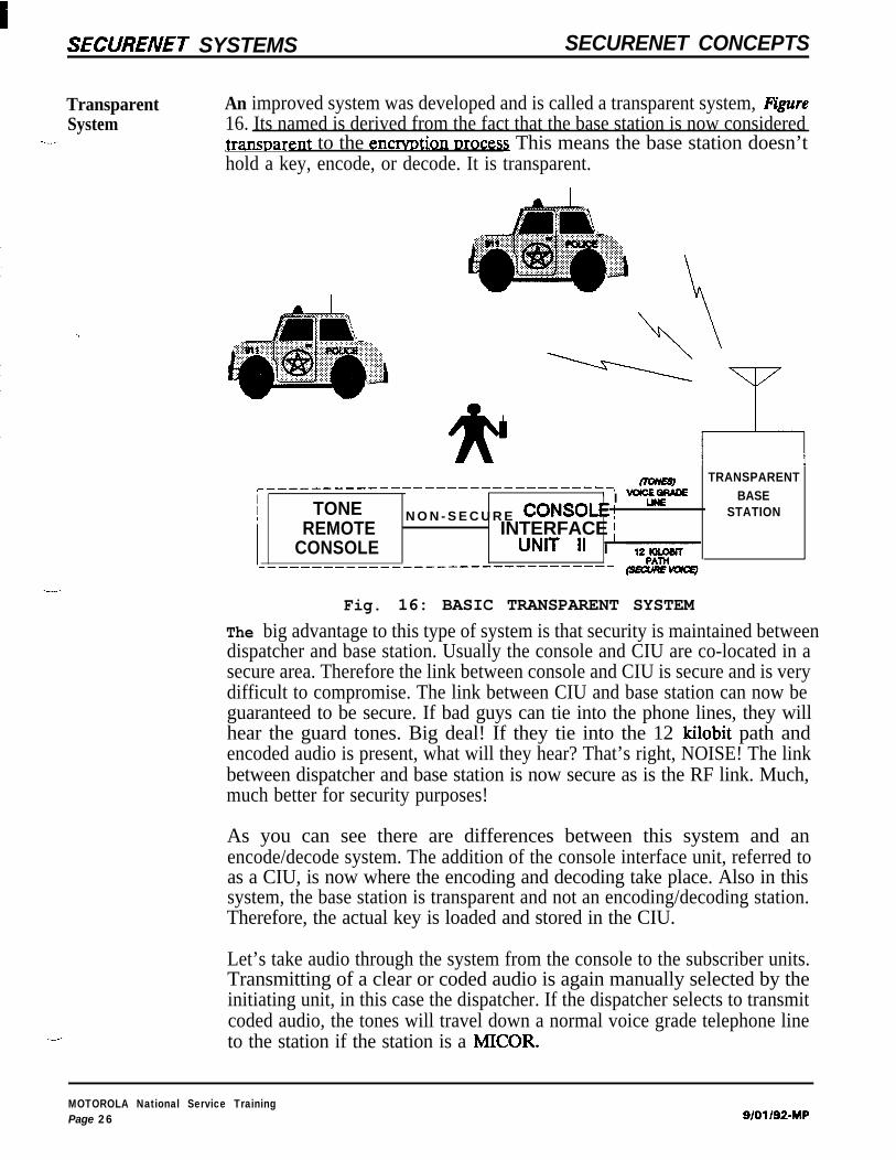
Transparent An improved system was developed and is called a transparent system, RgureSystem 16. Its named is derived from the fact that the base station is now considered
\-- transnarent to the encrvntion nrocm This means the base station doesn’thold a key, encode, or decode. It is transparent.
0 TRANSPARENT,_____-_____________-_________---------,I ’ I -fj- BASEI TONE STATIONI
REMOTEN O N - S E C U R E CoNSoLE ’
CONSOLEINTERFACE /
UNIT 11 I wPATH__----__---__-----------~~~~~~~~
mm
--Fig. 16: BASIC TRANSPARENT SYSTEM
The big advantage to this type of system is that security is maintained betweendispatcher and base station. Usually the console and CIU are co-located in asecure area. Therefore the link between console and CIU is secure and is verydifficult to compromise. The link between CIU and base station can now beguaranteed to be secure. If bad guys can tie into the phone lines, they willhear the guard tones. Big deal! If they tie into the 12 kilobit path andencoded audio is present, what will they hear? That’s right, NOISE! The linkbetween dispatcher and base station is now secure as is the RF link. Much,much better for security purposes!
As you can see there are differences between this system and anencode/decode system. The addition of the console interface unit, referred toas a CIU, is now where the encoding and decoding take place. Also in thissystem, the base station is transparent and not an encoding/decoding station.Therefore, the actual key is loaded and stored in the CIU.
Let’s take audio through the system from the console to the subscriber units.Transmitting of a clear or coded audio is again manually selected by theinitiating unit, in this case the dispatcher. If the dispatcher selects to transmitcoded audio, the tones will travel down a normal voice grade telephone lineto the station if the station is a MICOR.
MOTOROLA National Service TrainingPage 26 g/01/92-MP

SECURENET SYSTEMS SECURENET CONCEPTS
If the station is an MSF 5000, the tones will travel down the same path as theaudio. The tones will inform the station that encoded audio is coming and todisable the clear processing circuits and enable the coded processing circuits.The audio is encoded in the CIU and sent to the base station down a 12kilobit path. Due to the frequencies that comprise an encoded signal andbandwidth restrictions of a voice grade phone line, a dedicated path isrequired for the data. The base station then sends the encoded signal to themodulator and transmitted out into the air waves as a “scrambled” signal.
As far as the subscriber units are concerned in a transparent system, nothingdifferent takes place during receive or transmit conditions. For cleartransmission from base station to subscriber unit, the only difference is thatthe dispatcher selects to transmit in the clear. Next the console will now sendtones to inform the station to enable the clear audio processing circuits. Clearaudio is now sent to the CIU. The CIU does nothing with the audio but passit through and down the 12 kilobit path lines to the transmitter.
The exact opposite operation takes place when the subscriber unit wants totalk back to the dispatcher. The mobile or portable radio now converts theclear audio to a “scrambled” signal. Once again the operator of the subscriberunit has to select to transmit coded audio. The RF signal is now encrypted,and received by the base station, where it is processed but not decoded. Thestation outputs coded audio onto the 12 kilobit path line to the CIU where itis decoded. The clear audio from the CIU is sent to the dispatcher who willhear the audio at the console.
For clear transmissions from subscriber unit to the dispatcher, the subscriberoperator selects to transmit in the clear. The base station receives the RF,discriminates the signal to recover the audio, and sends it down the 12 kilobitpath to the CIU. The CIU passes the clear audio through and sends it to thedispatcher. A little bit different than an encode/decode system, but againnothing is done to the clear audio throughout the signal path.
-
9/o l/92-IMP
MOTOROLA National zkrviw TrainingP*ge 27
SECURENET SYSTEMS SECURENET CONCEPTS
ADDITIONAL READING
%ti The following materials were used as reference materials for part of the discussion. For moredetailed information concerning delta modulation, CVSD, analysis of eye patterns and testing fordistortion in the eye pattern please refer to these sources.
1.
2.
3.
4.;
5.
6.
7.
Advanced Digital Audio. Pohlmann, Ken C., ed. Carmel, Indiana: Sams, 1991.
Bellamy, John C. Digital Telenhonv. New York: John Wiley & Sons, 1982.
Hughes, Larry. Data Communication. New York: McGraw-Hill, Inc., 1992.
“SECURENET Digital Voice Protection System - System Planner.” Motorola, Inc.Schaumburg, IL. 1986. Manual No. R4-2-57A.
“SECURENET Systems Video.” Motorola, Inc. Schaumburg, IL. 1989. Video No. RO-15-02.
Smith, David R. Digital Transmission Svstems. New York: Van Norstrand Reinhold, 1985.
Transmission Svstems For Communications. Jordan and Penney, ed. Holmdel, New Jersey:Bell Telephone Laboratories, Inc., 1982.
MOTOROLA National Service TrainingPage 28 9/01/92-IMP