what is an industrial robot?
TRANSCRIPT

What is an industrial robot?C
Y
A kinematic chain
A robot is …
02
CFI
C A kinematic chain
A multi-body dynamical system
CFI
DV
A system with motors and drives
A system with digital and analogic sensors
CA
–0
1
An electronic system
A supervised and controlled system
OB
OTI
C A supervised and controlled system
A software driven system
RO Therefore … a mechatronic system
Basilio Bona – DAUIN – Politecnico di Torino 002/1
Industrial roboticsC
Y0
2C
FIC
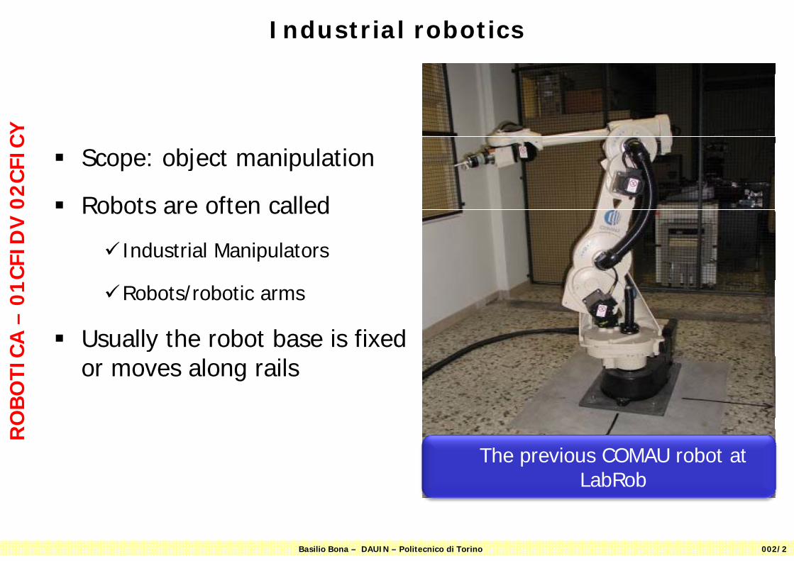
Scope: object manipulation
Robots are often called
CFI
DV
Robots are often called
Industrial Manipulators
CA
–0
1 Robots/robotic arms
Usually the robot base is fixed
OB
OTI
C yor moves along rails
RO
The previous COMAU robot at LabRob
Basilio Bona – DAUIN – Politecnico di Torino 002/2
LabRob

PrerequisitesC
Y Read Chapter 2 of the textbook
02
CFI
C
Reference systems
CFI
DV
yVectorsMatrices
CA
–0
1
Rotations, translations, roto-translationsHomogeneous representation of vectors
OB
OTI
C g pand matrices
RO
Basilio Bona – DAUIN – Politecnico di Torino 003/3
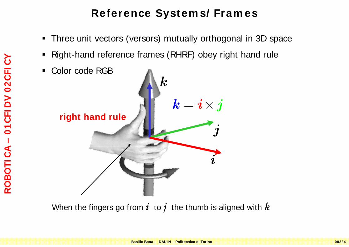
Reference Systems/FramesC
Y
Three unit vectors (versors) mutually orthogonal in 3D space
Right-hand reference frames (RHRF) obey right hand rule
02
CFI
C
Color code RGBk
CFI
DV
= ×k i jright hand rule
CA
–0
1 j
OB
OTI
C i
RO
When the fingers go from i to j the thumb is aligned with k
Basilio Bona – DAUIN – Politecnico di Torino 003/4
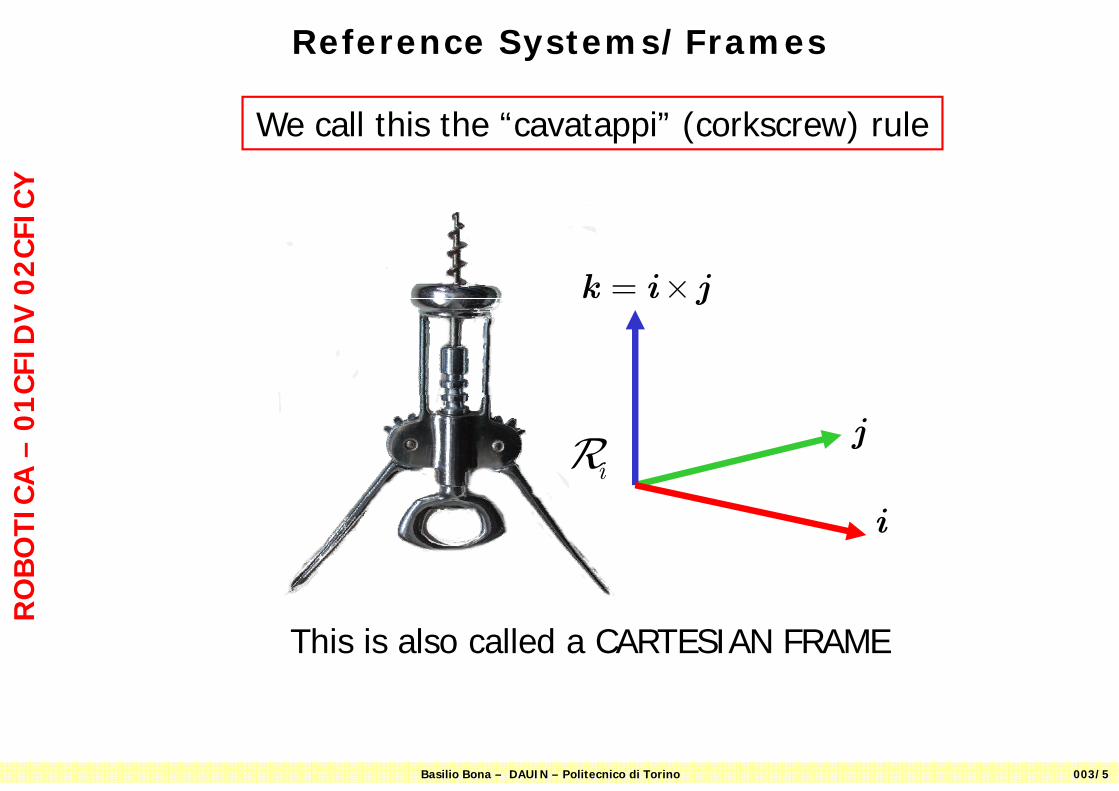
Reference Systems/FramesC
Y
We call this the “cavatappi” (corkscrew) rule
02
CFI
C
= ×k i j
CFI
DV
j
CA
–0
1
iRj
OB
OTI
C
i
RO
This is also called a CARTESIAN FRAME
Basilio Bona – DAUIN – Politecnico di Torino 003/5
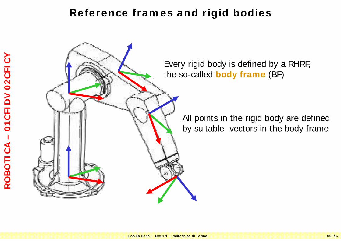
Reference frames and rigid bodiesC
Y
E i id b d i d fi d b RHRF
02
CFI
C Every rigid body is defined by a RHRF, the so-called body frame (BF)
CFI
DV
All points in the rigid body are defined
CA
–0
1 All points in the rigid body are defined by suitable vectors in the body frame
OB
OTI
CR
O
Basilio Bona – DAUIN – Politecnico di Torino 003/6
Vectors and MatricesC
Y Introductory notes on vectors and matrices can be found here
02
CFI
C
VECTORSVECTORShtt // l di lit it/M t i /01CFI/2008 09/Slid /V tt i df
CFI
DV
http://www.ladispe.polito.it/Meccatronica/01CFI/2008-09/Slides/Vettori.pdfhttp://www.ladispe.polito.it/Meccatronica/download/Appunti_matrici_vettori.pdf
CA
–0
1
MATRICESMATRICES
OB
OTI
C MATRICESMATRICEShttp://www.ladispe.polito.it/Meccatronica/01CFI/2008-09/Slides/Matrici.pdf
RO
Basilio Bona – DAUIN – Politecnico di Torino 003/7
KinematicsC
Y
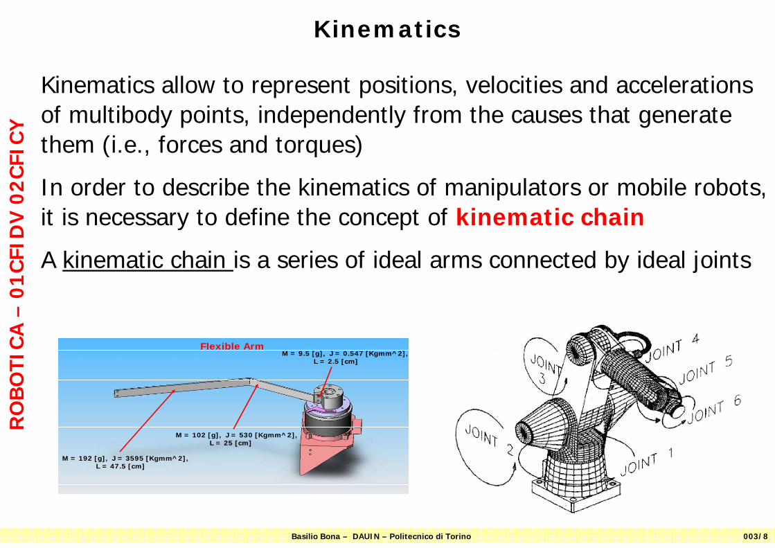
Kinematics allow to represent positions, velocities and accelerations of multibody points, independently from the causes that generate them (i e forces and torques)
02
CFI
C them (i.e., forces and torques)
In order to describe the kinematics of manipulators or mobile robots,
CFI
DV
it is necessary to define the concept of kinematic chain
A kinematic chain is a series of ideal arms connected by ideal joints
CA
–0
1O
BO
TIC Flexible Arm
M = 9.5 [g], J = 0.547 [Kgmm^2],L = 2.5 [cm]
RO
M = 102 [g], J = 530 [Kgmm^2],L = 25 [cm]
M = 192 [g], J = 3595 [Kgmm^2],L = 47.5 [cm]
Basilio Bona – DAUIN – Politecnico di Torino 003/8
Is the human arm a kinematic chain?C
Y
W i t
02
CFI
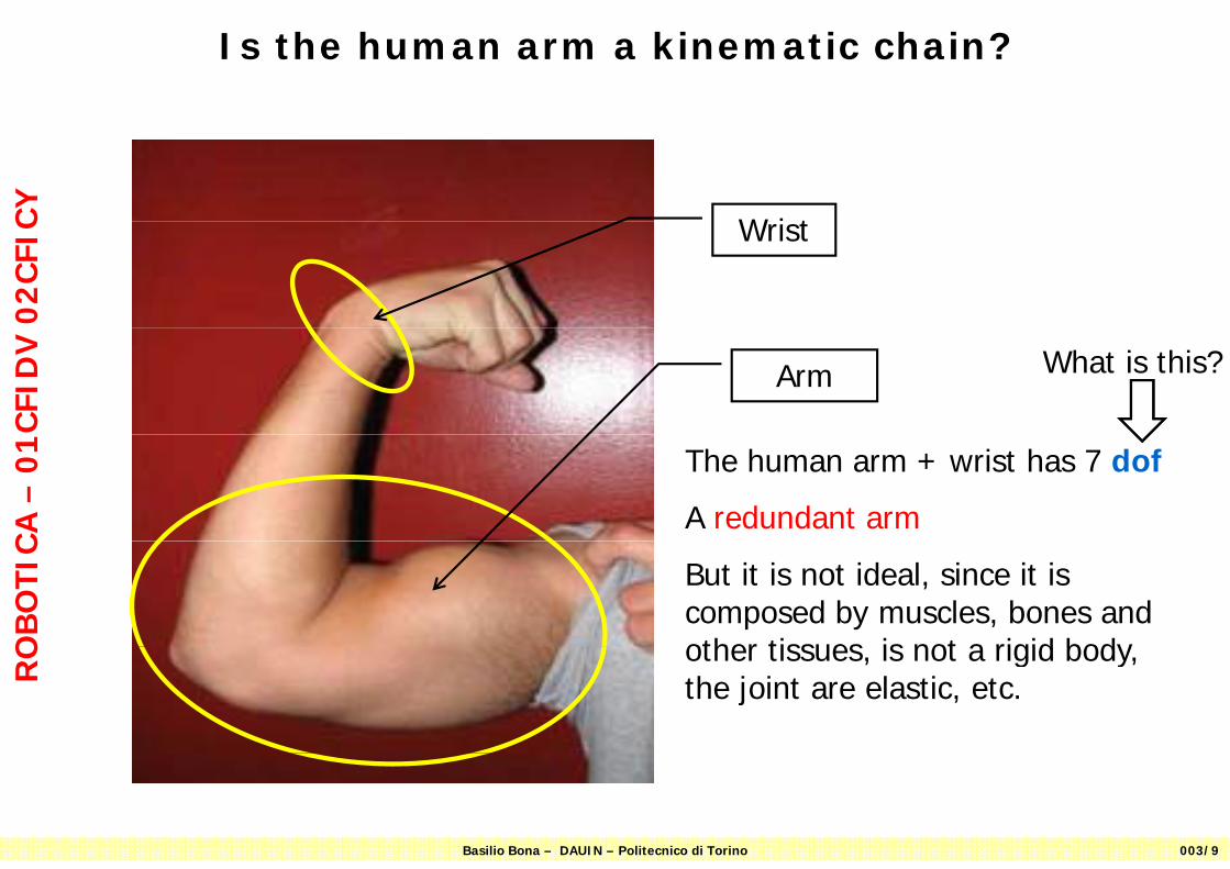
C Wrist
CFI
DV
Arm What is this?
CA
–0
1 The human arm + wrist has 7 dof
A redundant arm
OB
OTI
C
But it is not ideal, since it is composed by muscles, bones and other tissues is not a rigid body
RO other tissues, is not a rigid body,
the joint are elastic, etc.
Basilio Bona – DAUIN – Politecnico di Torino 003/9

Kinematic chainC
Y A kinematic chain KC is composed
02
CFI
C by a variable number ofArms/links (rigid and ideal)Joints (rigid and ideal)
CFI
DV
Joints (rigid and ideal)
It is defined only as a geometric entity (no mass, friction, etc.)
CA
–0
1
It has degrees of motion and degrees of freedom (DOF)
OB
OTI
C
One must be able to fix on each arm a RF -> DH conventions
b bl d bRO One must be able to describe every
possible point in a given RF
Basilio Bona – DAUIN – Politecnico di Torino 003/10
Kinematic chainC
Y
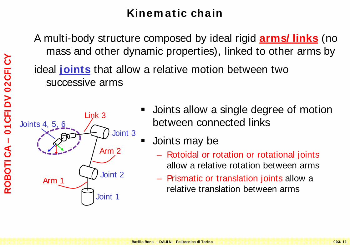
A multi-body structure composed by ideal rigid arms/links (no mass and other dynamic properties), linked to other arms by
02
CFI
C
ideal joints that allow a relative motion between two successive arms
CFI
DV
Joints 4 5 6Link 3 Joints allow a single degree of motion
between connected links
CA
–0
1
Joint 3Joints 4, 5, 6
Arm 2
between connected links
Joints may beRotoidal or rotation or rotational joints
OB
OTI
C
Joint 2Arm 1
– Rotoidal or rotation or rotational jointsallow a relative rotation between arms
– Prismatic or translation joints allow a
RO
Joint 1relative translation between arms
Basilio Bona – DAUIN – Politecnico di Torino 003/11
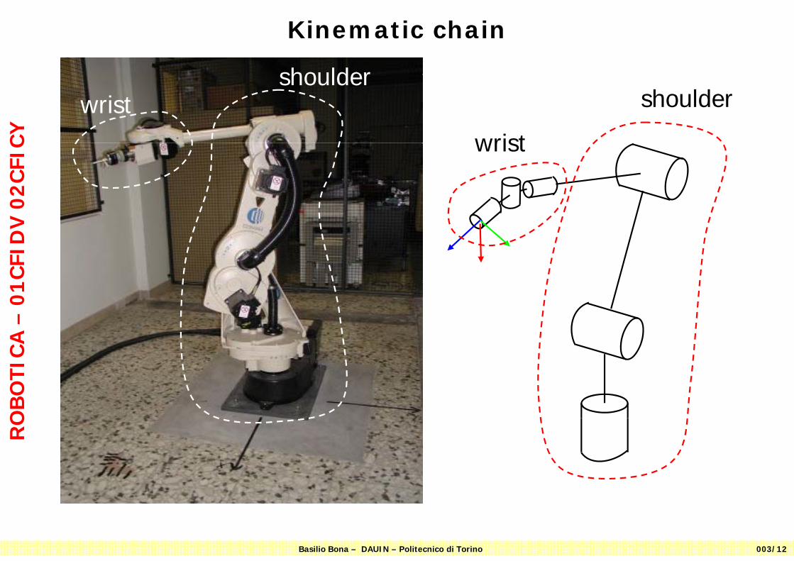
Kinematic chain
shoulder
CY
shoulder
wrist
wristshoulder
02
CFI
C wrist
CFI
DV
C
A –
01
OB
OTI
CR
O
Basilio Bona – DAUIN – Politecnico di Torino 003/12

Rotation Joints
How we draw joints and links?How we draw joints and links?
CY Rotation joints are draw in 3D perspective as
small cylinders with axes aligned along each
How we draw joints and links?How we draw joints and links?
02
CFI
C small cylinders with axes aligned along each rotation axis k
CFI
DV
j
CA
–0
1
ij
OB
OTI
C
Rotation joints are draw in 2D as small circles or small hourglasses
RO
jik
axis is normal to the planepointing toward the observer
Basilio Bona – DAUIN – Politecnico di Torino 003/13
jk
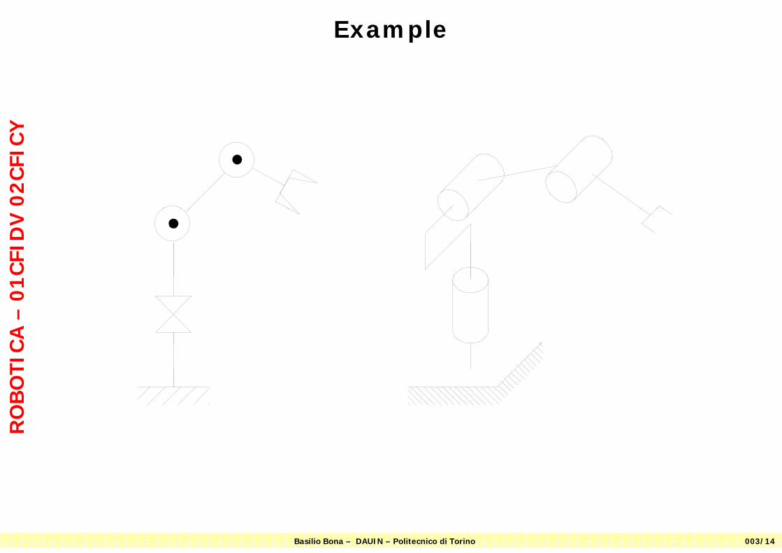
ExampleC
Y0
2C
FIC
CFI
DV
C
A –
01
OB
OTI
CR
O
Basilio Bona – DAUIN – Politecnico di Torino 003/14
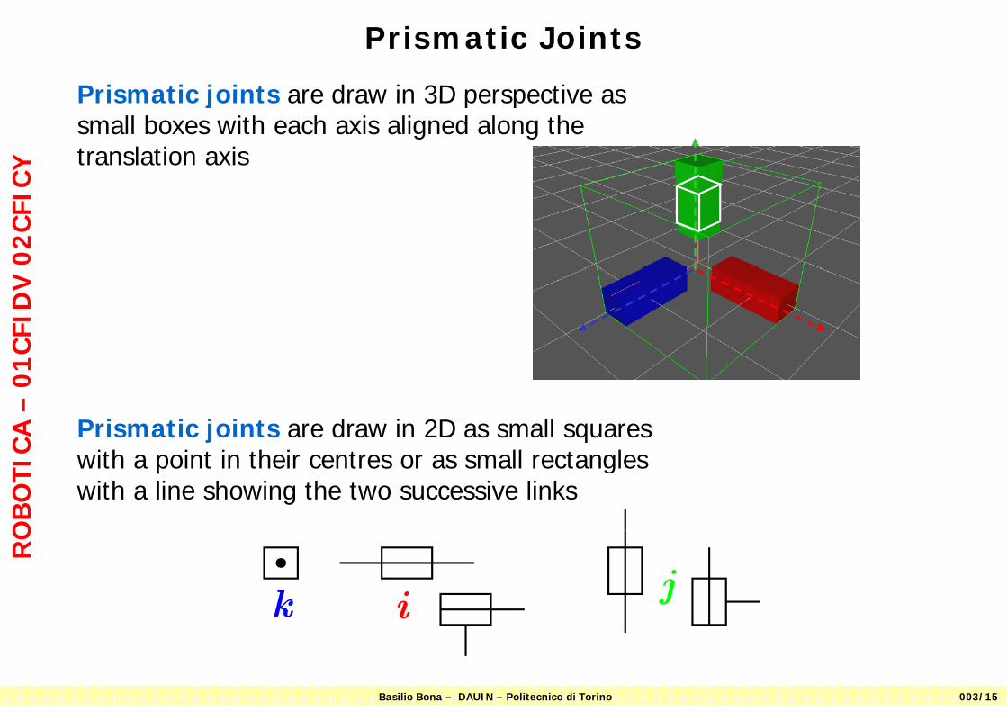
Prismatic Joints
Prismatic joints are draw in 3D perspective as
CY
Prismatic joints are draw in 3D perspective as small boxes with each axis aligned along the translation axis
02
CFI
CC
FID
V
CA
–0
1
Prismatic joints are draw in 2D as small squares
OB
OTI
C with a point in their centres or as small rectangles with a line showing the two successive links
RO
jik
Basilio Bona – DAUIN – Politecnico di Torino 003/15
i
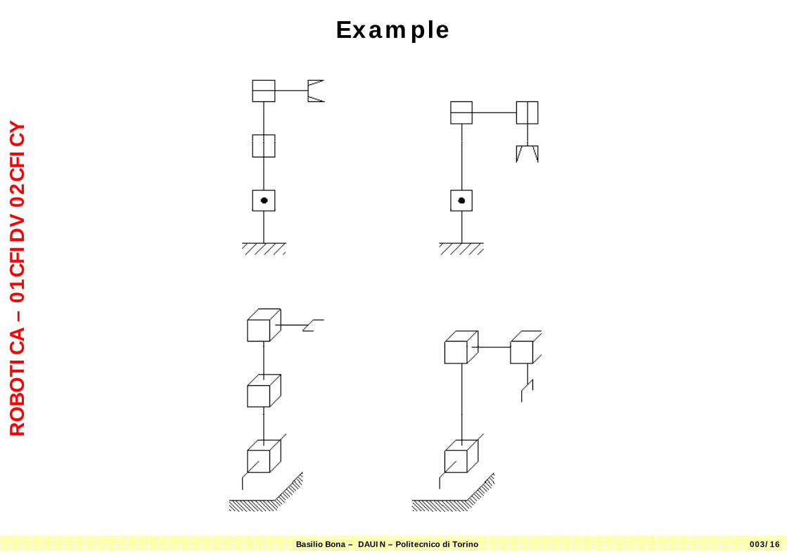
ExampleC
Y0
2C
FIC
CFI
DV
C
A –
01
OB
OTI
CR
O
Basilio Bona – DAUIN – Politecnico di Torino 003/16
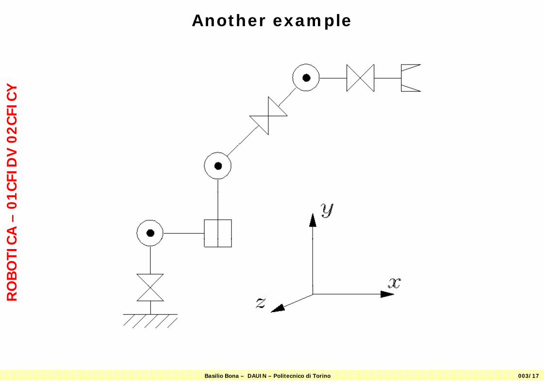
Another exampleC
Y0
2C
FIC
CFI
DV
C
A –
01
OB
OTI
CR
O
Basilio Bona – DAUIN – Politecnico di Torino 003/17

Kinematic chainC
Y The COMAU robot seen as an ideal kinematic chain
02
CFI
CC
FID
V
CA
–0
1O
BO
TIC
RO
Basilio Bona – DAUIN – Politecnico di Torino 003/18
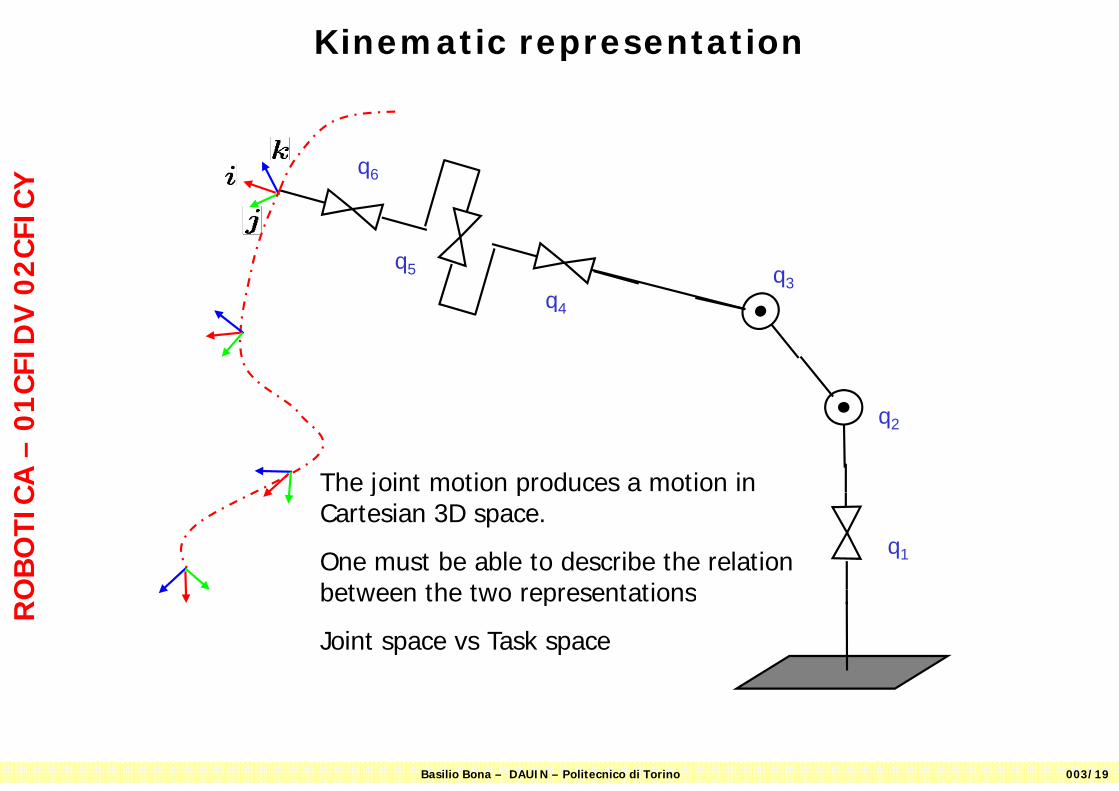
Kinematic representationC
Y q6
02
CFI
C
q3q
q5
CFI
DV
q4
CA
–0
1
The joint motion produces a motion in
q2
OB
OTI
C j pCartesian 3D space.
One must be able to describe the relation between the two representations
q1
RO between the two representations
Joint space vs Task space
Basilio Bona – DAUIN – Politecnico di Torino 003/19

Joint space and task spaceC
Y
Task Space (Cartesian)
02
CFI
C
Joint space
Task Space (Cartesian)
z
CFI
DV
63qdirect
CA
–0
1
y
n
i
OB
OTI
C x y
q2q
inverse
RO
1q
direct kinematics is easier than inverse kinematics
Basilio Bona – DAUIN – Politecnico di Torino 003/20

Task SpaceC
Y
Task Space Operational Space
WorkspaceAre synonymous
02
CFI
C p
CFI
DV
C
A –
01
OB
OTI
CR
O
Basilio Bona – DAUIN – Politecnico di Torino 003/21
Degrees of motion and degrees of freedomC
Y The degrees of motion (dom as they are called) count the
02
CFI
C The degrees of motion (dom, as they are called) count the number of prismatic/rotation joints (active, i.e., motor-driven or passive)
CFI
DV
The degrees of freedom (dof, as they are called) count the number of free parameters of the considered body
CA
–0
1 number of free parameters of the considered body
Dofs may be referred to manipulator, when they count what it can do with its center point or to the task when measure what
OB
OTI
C can do with its center point, or to the task when measure what is required by the application
RO
Basilio Bona – DAUIN – Politecnico di Torino 003/22
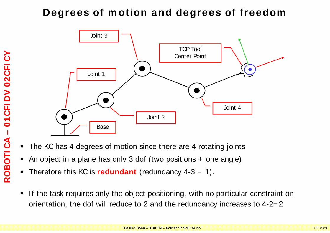
Degrees of motion and degrees of freedomC
Y TCP Tool Center Point
Joint 3
02
CFI
C
Joint 1
CFI
DV
Joint 4
Joint 2
CA
–0
1 Joint 2
Base
The KC has 4 degrees of motion since there are 4 rotating joints
OB
OTI
C The KC has 4 degrees of motion since there are 4 rotating joints
An object in a plane has only 3 dof (two positions + one angle)
Therefore this KC is redundant (redundancy 4-3 = 1).
RO Therefore this KC is redundant (redundancy 4 3 1).
If the task requires only the object positioning, with no particular constraint on i t ti th d f ill d t 2 d th d d i t 4 2 2
Basilio Bona – DAUIN – Politecnico di Torino 003/23
orientation, the dof will reduce to 2 and the redundancy increases to 4-2=2

Often one reads that a robot control is able to manage, e.g., 8 dof.
This sentence should be correctly understood, since it means that the robot is able
CY
to control 8 degrees of motion.
In the example below the robot has 5 dof and 5 dom, and the additional 3 dom on
02
CFI
C
the rotating fixture are useful only for part machining.
The task on parts on the rotating fixtures requires 5 or 6 dof.
CFI
DV
C
A –
01
OB
OTI
CR
O
E l f b t ith l t ti fi t
Basilio Bona – DAUIN – Politecnico di Torino 003/24
Example of a robot with a slave rotating fixture with additional degrees of motion
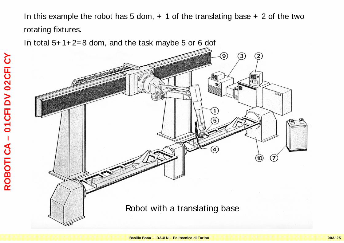
In this example the robot has 5 dom, + 1 of the translating base + 2 of the two
rotating fixtures.
CY
otat g tu es
In total 5+1+2=8 dom, and the task maybe 5 or 6 dof
02
CFI
CC
FID
V
CA
–0
1O
BO
TIC
RO
Robot with a translating base
Basilio Bona – DAUIN – Politecnico di Torino 003/25
Robot with a translating base