what engineers need to know about testing and balancing … · what engineers need to know about...
TRANSCRIPT
N0-94-4-1
AIVC #13,502
WHAT ENGINEERS NEED TO KNOW ABOUT TESTING AND BALANCING
W, David Bevirt, P .E. Fellow/Life Member ASHRAE
INTRODUCTION
Heating, ventilating, and air-conditionina (Hv'AC) systems, as we know them today, were not installed urHil after World War II. Prior to this, except for some very large buildings (such as auditoriums, department stores, large theaters, and a few high-rise buildings), most commercial and institutional buildings, such as hospitals, schools, and offices, were heated with steam or hot water cast iron radiators. Some had mechanical ventilation. systems; few, if any, had refrigerated cooling.
Later, as architects began using more glass in sealed buildings, HY AC system design engineers sought new equipment and systems to cope with the changing loads and ventilation requirements. The HY AC systems became more complicated. to design, install, and operate, and most did not fully satisfy the comfort of the occupants when put into operation.
Although carefully designed, factors such as job conditions, substituted equipment, variations in workmanship, and changing load conditions created a requirement that the air and bydronic systems bad to be tested and balanced in order for the HY AC system to operate satisfactorily. Unfortunately, most testing and balancing work was haphazard and poorly executed, creating a need for trained testing, adjusting, and balancing (TAB) personnel who could provide professional and accurate TAB work for the HY AC industry.
TAB STANDARDS
Today, HY AC system· design engineers have several recognized industry procedural standards or guidelines to use when writing TAB specifications for each project. These standards or guidelines, which contain TAB procedures or practices, vary in format, content, and data. But all provide proven and reliable information for use in field testing and the reporting of test results that are accurate within the stated limitations. Publications available to HV AC system engineers on TAB procedures and practices include the following:
ANSl/ASHRAE 111-1988, Practices for Measurement, Testing, Adjusting, and Balancing of Building
Heating, Ventilation, Air-Conditioning and Refriieration Systems
Associated Air Balance Council (AABC), 1989-National Standards for Testing and Balanci11g Heating, Ventilating, and Air Conditioning Systems
National Environmental Balancing Bureau (NEBB), 1991-Procedural Standards for Testing, Adjusting, Balancing of Environmental Systems
Sheet Metal and Air Conditioning Contractors National Association (SMACNA), 1993-HVAC SystemsTesting, Adjusting, and Balancing manual
NATIONAL RECOGNIZED TAB PROGRAMS
In addition to effective procedural standards, trained personnel were needed who could provide professional and accurate TAB work for the HY AC industry. This led to the establishment of several nationally and/or internationally recognized TAB agencies with certified TAB programs at the supervisory or technician level. There are also state or local TAB programs that are accepted by specifying authorities in the areas of operation.
AABC and NEBB have certified TAB programs that operate internationally at the supervisory level. The National Training Fund (NTF) of the sheet metal industry has a certified TAB technician program available in the United States. All of these programs have guarantees or warranties that ensure on-the-job performance of its member firms or technicians. Details of the programs vary, but all were established to improve the quality of TAB work and the resultant reports received by the HY AC system design engineer. It is most important to note that the experience levels, training, and testing of all TAB personnel in these programs have been documented, and only qualified performance will allow them to keep their certifications.
SPECIFICATIONS AND DRAWINGS
All of the TAB standards or publications listed above contain sample TAB specifications. A composite of these sample specifications may be written into project specifications; most often they are referenced by name. Specifications should provide complete information to do the job.
W. David Bevirt is technical director for the National Environemental Balancing Bureau, Tucson AZ.
ASHRAE Transactions: Symposia 705
Some HV AC system design engineers do not provide detailed information on fan capacity selection and they do not show balancing devices (such as valves and dampers) on
the project drawings. In addition, duct system air leakage
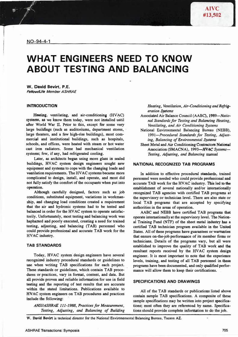
may be overlooked. For example, the amount of HV AC system air leakage can be predicted by using data from Figure 1 and Tables 1 and 2 (ASHRAE 1989). The calculated amount of air leakage should be added to the selected fan capacity and so noted either in the specifications or on the drawings. This allows the TAB technician to more easily verify actual system conditions, and the originally installed fan drives should still be able to be used after completion of the TAB work. Many fan drives, fan motors, and electrical services to the fans have had to be changed because duct system air leakage was ignored by the system designer.
AWARD OF TAB WORK
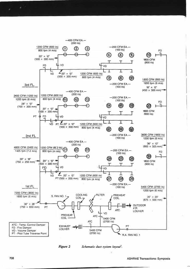
Regardless of who is responsible for the TAB work, the contract for the HV AC systems TAB work should be awarded before the project construction actually begins. This allows the TAB firm to review the projects HV AC system drawings and make a schematic drawing (NEBB 1991) similar to that in Figure 2, which shows system details including balancing devices. A similar schematic drawing should be made for more complicated hydronic systems (i.e., when multiple radiation and fan-coil units and risers are used). The absence of balancing devices and/or
glaring system deficiencies should become apparent at this
time. During HV AC system installation, on-site job inspec
tions should determine whether all balancing devices have been installed and are accessible. Equipment shop drawings should be reviewed and preliminary data entered on the
TAB test report forms.
SYSTEM DEFICIENCIES
There are three major deficiencies that can develop in
HV AC duct systems and some additional ones in HV AC hydronic systems. Some inadvertently may be designed into
the systems by the design engineer and others may be
created by the system installers. All create problems for the
TAB firm and everyone else involved.
In air systems, the problems are
• duct air leakage, • system effect, and • excessive fitting pressure drops.
In addition to fan selection, another problem with duct
leakage is that many HV AC system designers specify a maximum of 1 % air leakage from systems in the 4 in. to 6 in. w.g. (1,000 to 1,500 Pa) pressure classification for duct construction. When fully sealed round ductwork of leakage class 3, the lowest leakage class from Table 1 (ASHRAE
706
STATIC PRESSURE (Op), in of waler
Figure 1 Duct leakage classifications1•
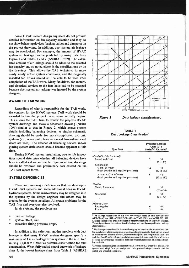
TABLE 1 Duct Leakage Classification 1
'fype Duct
Me1al (Flexible Excluded) Round and Oval
Rectangular , � 2 in. of water (both positive and negative pressu.res)
> 2 and �10 in. of water (both positive and negative pressures)
Flexible Metal, Aluminum
Nonmetal
Fibrous Glass Rectangular Round
Predicted Leakage Class (CL)
Sealedb,c Unsealed<
3 30 (6 to 70)
12 48 (12to 110)
6 48 (12 to 110)
8 30 (12 to 54)
12 30 (4 10 54)
6 NA 3, NA
•The leakage classes listed in this table arc averages based on tests conducted by AISl/SMACNA 1972, ASHRAE/SMACNA/TIMA 1985, and ASHRAE 1988.
Leakage classes listed arc not necessarily recommendations on allowable leakage. The designer should determine allowable leakage and specify acceptable duct leakage classifications.
b The leakage classes listed in the scaled category arc based on the a.ssumptions that for metal ducts all t ransvcrsc joints, scams, and openings in the duct wall arc scaled at pressures over 3 inches of water, Lhal transverse joints-and longitudinal scams arc sealed at 2 and 3 inches of water, and that transverse joints arc scaled below 2 inches of wam. Lower leakage classes arc obtained by careful selection of joints and seal· ing methods.
c Leakage classes assigned anticipate about 2S joints per 100 linear foot of duct. For systems with a high fitting to straight duct ratio, greater kMkagc occurs in both the scaled and unscaled conditions.
ASHRAE Transactions: Symposia
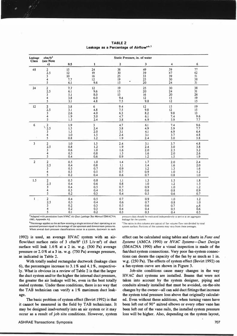
TABLE 2 Leakage as a Percentage of Airflow•·b· 1
Leakage Class
cfm/ft1 Static Pressure, in. of water (see Note
c) 0.5 1 48 2 15 24
2.5 12 19 3 10 16 4 7.7 12 5 6.1 9.6
24 2 7.7 12 2.5 6.1 9.6 3 5.1 8.0 4 3.8 6.0 5 3.1 4.8
12 2 3.8 6 2.5 3.1 4.8 3 2.6 4.0 4 1.9 3.0 5 1.5 2.4
6 2 1.9 3 2.5 1.5 2.4 3 1.3 2.0 4 1.0 1.5 5 0.8 1.2
3 2 1.0 1.5 2.5 0.8 1.2 3 0.6 1.0 4 0.5 0.8 5 0.4 0.6
2 2 0.5 1.0 2.5 0.4 0.8 3 0.3 0.7 4 0.3 0.5 5 0.2 0.4
1.5 2 0.5 0.8 2.5 0.4 0.6 3 0.4 0.5 4 0.3 0.4 5 0.2 0.3
l . 2 0.4 0.5 2.5 0.3 0.4 3 0.2 0.3 4 0.2 0.3 5 0.1 0.2
•Adapted with permission from HVAC Air Duer leakage Tes/ Manuul (SM AC NA 1985, Appendix A). bPerccntagc applies lo the airflow entering a single section of duct operating al an assumed pressure equal LO the average of lhe upstream and downstream pressures. When several duct pressure classifications occur in a system, ductwork in each
1992) is used, an average HVAC system with an airflow/duct surface ratio of 3 cfm/ft2 (15 L/s·m2) of duct surface will leak 1.6 % at a 2 in. w.g. (500 Pa) average pressure or 2.0% at a 3 in. w.g. (750 Pa) average pressure, as indicated in Table 2.
With totally sealed rectangular ductwork (leakage class 6), the percentages increase to 3.1 % and 4.1 % , respectively. What is obvious in a review of Table 2 is that the larger the duct system and/or the higher the internal duct pressure, the greater the air leakage will be, even in the best totally sealed systems. Under these conditions, there is no way that the TAB technician can verify a 1 % maximum duct leakage.
The basic problem of system effect (Bevirt 1992) is that it cannot be measured in the field by TAB technicians. It may be designed inadvertently into an air system or it may occur as a result of job site conditions. However, system
ASH RAE Transactions: Symposia
2 3 4 6
38 49 59 77 30 39 47 62 25 33 39 51 19 25 30 38 15 20 24 31
19 25 30 38 15 20 24 31 13 16 20 26
9.4 12 15 19 7.5 9.8 12 15
9.4 12 15 19 7.5 9.8 12 15 6.3 8.2 9.8 13 4.7 6.1 7.4 9.6 3.8 4.9 5.9 7.7
4.7 6.1 7.4 9.6 3.8 4.9 5.9 7.7 3.1 4.1 4.9 6.4 2.4 3.1 3.7 4.8 1.9 2.4 3.0 3.8
2.4 3.1 3.7 4.8 1.9 2.4 3.0 3.8 1.6 2.0 2.5 3.2 1.3 1.6 2.0 2.6 0.9 1.2 1.5 1.9
l.4 1.7 2.0 2.4 I.I 1.4 l.6 2.0 0.9 1.2 1.3 1.6 0.7 0.9 1.0 1.2 0.6 0.7 0.8 1.0
1.1 1.3 1.5 1.8 0.8 1.0 l.2 1.5 0.7 0.9 1.0 1.2 0.5 0.6 0.8 0.9 0.4 0.5 0.6 0.7
0.7 0.9 l.O 1.2 0.6 0.7 0.8 1.0 0.5 0.6 0.7 0.8 0.4 0.4 0.5 0.6 0.3 0.3 0.4 0.5
pressure class should be evaluall!d independen1ly to arrive ar an aggregatl! leakage for lhe system.
�The ratios in this column are rypical or fan volume flow rate divided b}' total sysrc:m surface. Porrions or the syscems may vary from these averages.
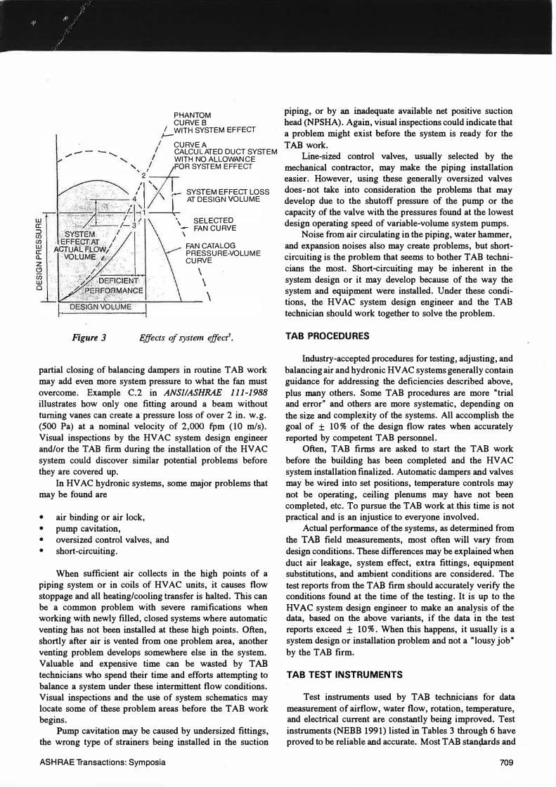
effect can be calculated using tables and charts in Fans and Systems (AMCA 1990) or HVAC Systems-Duct Design (SMACNA 1990) after a visual inspection is made of the fan/duct system connections. Very poor fan-system connections can derate the capacity of the fan by as much as 1 in. w.g. (250 Pa). The effects of system effect (Bevirt 1992) on �fan-system curve are shown in Figure 3.
Job-site conditions cause many changes in the way HV AC duct systems are installed. Beams that were not taken into account by the system designer, piping and conduits already installed that must be avoided, on-the-site changes by the owner-all can add duct fittings that increase the system total pressure loss above that originally calculated. Even without these additions, when turning vanes have been left out of 90° mitred elbows or every other vane has been left out of the vane rails, the installed system pressure loss will be higher. Also, depending on the system layout,
707
1200 CFM (600 Its) 800 fpm (4 mis)
20" x 12" (500 x 300 mm)
FD VD
-400 CFM EA.(200 Ifs)
20" x 12" (500 x 300 mm)·
1200 CFM (600 Ifs)
800 fpm (4 mis)
3rd FL.
2400 CFM (1200 Its) 1200 CFM (600 Its) -400 CFM EA.
(200 Ifs)
1200 fpm (6 mis) 800 fpm (4 mis) @ @ 28" x 12"
(700 x 300 mm)
PT
20" x 12" (500 x 300 mm)
FD
PT 20" x 12" 1200 CFM (600 Ifs)
-200 CFM EA.(100 Its)
tr;:\ � I?\ �
-200 CFM EA.(100 Ifs)
-200 CFM EA.(100 Ifs)
@)
(500 x 300 mm) 800 fpm (4 mis) @
-400 CFM EA.(200 Its)
4800 CFM (2400 Its) 1200 CFM (6C J l/s) t2r 1425 fpm (7.2 mis) 800 fpm (4 rn/s) �
-200 CFM EA.(100 Its)
-200 CFM EA.(100 Its)
aA\ w 1800 CFM
(900 Ifs)
FD
1800 CFM (900 Its)
1200 fpm (6 mis)
18" x 12" (450 x 300 mm)
1800 CFM (900 Its)
FD
3600 CFM (1800 Its) 1 200 fpm (6 mis)
36" x 13" (900 x 325 mm)
FD
30" x 18" (750 x 250 mm) @ @ @ @)
1800 CFM (900 Its)
1st FL -----
7200 CFM (3600 Its) 1600 fpm (8 mis)
30" x 26" (750 x 650 mm) PT
ATC_ Temp. Control Damper FD - Fire Damper VD - Volume Damper PT_ Pitot Tube Traverse Point
708
. 20" x 12" 1200 CFM (600 l/s) PT (500 x 200 mm) 800 fpm (4 mis) � �
-200 CFM EA.(100 Ifs)
S. FAN NO. 1
ATC
ATC
VD
5400 CFM (2700 Ifs)
EXHAUST �Ill---+--_.__--; LOUVER 5400 CFM (2700 Ifs)
Figure 2 Schematic duct system layour.
PT
5400 CFM (2700 lis) 1200 fpm (6 mis)
35" x 20" (675 x 500 mm)
OUTDOOR Jl!R LOUVER
ASHRAE Transactions: Symposia
PHANTOM CURVES
I WITH SYSTEM EF FECT ,__ . I CURVEA - - - ......_ I CALCULATED DUC T SYSTEM ,,,-
....,_ II WITH NO ALLOWANC E
' !FOR SYSTEM E FFECT
/1',,\ .-- SYSTEM EFFECT L OSS
<'�r:::�·�:-�,..·i.-.�· -·�-.:-1-t�i�i W- AT DESIGN VOLUME
� · • ·': i" ;_ : · I- 3 ( \ S EL ECTED :::> . / ·.P.::. ,...
/ - FAN CURVE <n ·),SYSTEM. I \ (f) EF.�E..cm�T . I FAN CATALO G � • AQJUA� Rl-O'fV1. PRESSURE-VOLUME a. VOLtJME; '!.: CURVE z •" -�· (!) ,,. / •• : • \ Ci5 • • • . ,.. /.'; , . . w . .."*" �,-d::>E�l.QIEN_T' · \ o . · ':\�:.�����MP:NC E
\ . DE$fGWJOLUME I Figure 3 Effects of system effecf.
partial closing of balancing dampers in routine TAB work may add even more system pressure to what the fan must overcome. Example C.2 in ANSIIASHRAE 111-1988 illustrates how only one fitting around a beam without turning vanes can create a·pressure loss of over 2 in. w.g. (500 Pa) at a nominal velocity of 2,000 fpm (10 mis). Visual inspections by the HVAC system design engineer and/or the TAB firm during the installation of the HV AC system could discover similar potential problems before they are covered up.
In HV AC hydronic systems, some major problems that may be found are
• air binding or air lock, • pump cavitation, • oversized control valves, and • short-circuiting.
When sufficient air collects in the high points of a piping system or in coils of HV AC units, it causes flow stoppage and all heating/cooling transfer is halted. This can be a common problem with severe ramifications when working with newly filled, closed systems where automatic venting has not been installed at these high points. Often, shortly after air is vented from one problem area, another venting problem develops somewhere else in the system. Valuable and expensive time can be wasted by TAB technicians who spend their time and efforts attempting to balance a system under these intermittent flow conditions. Visual inspections and the use of system schematics may locate some of these problem areas before the TAB work begins.
Pump cavitation may be caused by undersized fittings, the wrong type of strainers being installed in the suction
ASH RAE Transactions: Symposia
piping, or by an inadequate available net positive suction head (NPSHA). Again, visual inspections could indicate that a problem might exist before the system is ready for the TAB work.
Line-sized control valves, usually selected by the mechanical contractor, may make the piping installation easier. However, using these generally oversized valves does-not take into consideration the problems that may develop due to the shutoff pressure of the pump or the capacity of the valve with the pressures found at the lowest design operating speed of variable-volume system pumps.
Noise from air circulating in the piping, water hammer, and expansion noises also may create problems, but shortcircuiting is the problem that seems to bother TAB technicians the most. Short-circuiting may be inherent in the system design or it may develop because of the way the system and equipment were installed. Under these conditions, the HV AC system design engineer and the TAB technician should work together to solve the problem.
TAB PROCEDURES
Industry-accepted procedures for testing, adjusting, and balancing air and hydronic HV AC systems generally contain guidance for addressing the deficiencies described above, plus many others. Some TAB procedures are more "trial and error" and others are more systematic, depending on the size and complexity of the systems. All accomplish the goal of ± 10% of the design flow rates when accurately reported by competent TAB personnel.
Often, TAB firms are asked to start the TAB work before the building has been completed and the HVAC system installation finalized. Automatic dampers and valves may be wired into set positions, temperature controls may not be operating, ceiling plenums may have not been completed, etc. To pursue the TAB work at .this time is not practical and is an injustice to everyone involved.
Actual performance of the systems, as determined from the TAB field measurements, most often will vary from design conditions. These differences may be explained when duct air leakage, system effect, extra fittings, equipment substitutions, and ambient conditions are considered. The test reports from the TAB firm should accurately verify the conditions found at the time of the testing. It is up to the HV AC system design engineer to make an analysis of the data, based on the above variants, if the data in the test reports exceed ± IO%. When this happens, it usually is a system design or installation problem and not a "lousy job" by the TAB firm.
TAB TEST INSTRUMENTS
Test instruments used by TAB technicians for data measurement of airflow, water flow, rotation, temperature, and electrical current are constantly being improved. Test instruments (NEBB 1991) listed 'in Tables 3 through 6 have proved to be reliable and accurate. Most TAB stan!;lards and
709
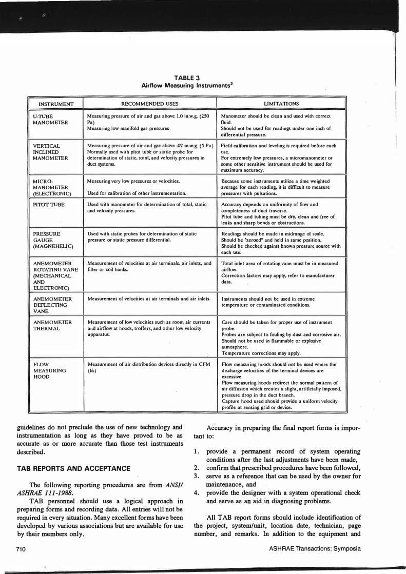
TABLE 3 Airflow Measuring lnstruments2
I INSTRUMENT I RECOMMENDED USES I LIMITATIONS I U-11.JBE Measuring pressure of air and gas above 1.0 in.w.g. (250 Manome1er should be clean and used wilh correcl MANOMETER Pa) fluid.
Measuring low manifold gas pressures Should not be used for readings under one inch of differenlial pressure.
VERTICAL Measuring pressure of air and g11s above .02 in.w.g. (5 Pa) Field calibration and leveling is required before each INCLINED Normally used wilh pitot tube or slatic probe for use. MANOMETER determinalion of sta1ic, total, and velocity pressures in For extremely low pressures, a micromanometer or
duct systems. some other sensitive inslrument should be used for maximum accuracy.
MICRO- Measuring very low pressures or velocities. Because some instruments utilize a time weighted MANOMETER average for each reading, it is difficull lo measure (ELECTRONIC) Used for calibration of other instrumentation. pressures with pulsations.
PITOTTI.JBE Used with manometer for determination of total, static Accuracy depends on uniformily of flow and and velocity pressures. completeness of duct traverse.
Pilot tube and tubing must be dry, clean and free of leaks and sharp bends or obstructions.
PRESSURE Used with static probes for determination of static Readings should be made in midrange of scale. GAUGE pressure or static pressure differential. Should be "zeroed" and held in same posilion. (MAGNEHELIC) Should be checked against known pressure source wilh
each use.
ANEMOMETER Measurement of velocilies al air terminals, air inlets, and Total inlet area of rotating vane must be in measured ROTATING VANE filler or coil banks. airflow. (MECHANICAL Correction factors may apply, refer to manufacturer AND dala. ELECTRONIC)
ANEMOMETER Measuremenl of velocities at air terminals and air inlets. Inslrumenls should not be used in exlreme DEFLECTING lemperalure or contaminaled condilions. VANE
ANEMOMETER Measuremenl of low velocilies such as room air currenls Care should be taken for proper use of inslrument THERMAL and airflow al hoods, lroffers, and olher low velocity probe.
apparalus. Probes are subjecl lo fouling by dusl and corrosive air. Should not be used in flammable or explosive atmosphere. Temperature corrections may apply.
FLOW Measuremenl of air distribulion devices directly in CFM Flow measuring hoods should 'nol be used where lhe MEASURING (l/s) HOOD
guidelines do not preclude the use of new technology and instrumentation as long as they· have proved to be as accurate as or more accurate than those test instruments described.
TAB REPORTS AND ACCEPTANCE
The following reporting procedures are from ANSI/ ASHRAE 111-1988.
TAB personnel should use a logical approach in preparing forms and recording data. All entries will not be required in every situation. Many excellent forms have been developed by various associations but are available for use by their members only.
710
discharge velocities of the terminal devices are excessive. Flow measuring hoods redirect lhe normal pallern of air diffusion which creates a slight, arlificially imposed, pressure drop in the duct branch. Capture hood used should provide a uniform velocity profile al sensing grid or device.
Accuracy in preparing the final report forms is important to:
1. provide a permanent record of system operating conditions after the last adjustments have been made,
2. confirm that prescribed procedures have been followed, 3. serve as a reference that can be used by the owner for
maintenance, and 4. provide the designer with a system operational check
and serve as an aid in diagnosing problems.
All TAB report forms should include identification of the project, system/unit, location date, technician, page number, and remarks. In addition to the equipment and
ASHRAE Transactions: Symposia
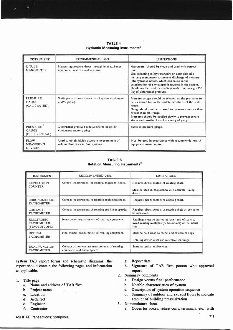
TABLE 4 Hydronic Measuring lnstruments2
INSTRUMENT RECOMMENDED USES LIMITATIONS
U-TUDE Measuring pressure drops through heat exchange Manometer should be clean and used with correct MANOMETER equipment, orifices, and venturis. fluid.
Use collecting safety reservoirs on each side of a mercury manometer to prevent discharge of mercury . into hydronic system, which can cause rapid deterioration of any copper it touches in the system. Should not be used for readings under one in.w.g. (250 Pa) of differential pressure.
PRESSURE Static pressure measurements or system equipment Pressure gauges should be selected so the pressures to GAUGE and/or piping. be measured fall in the middle two-thirds or the scale (CALIBRATED) range.
Gauge should not be exposed lo pressures grenler than or less than dial range. Pressures should be applied slowly to prevent severe strain and possible loss of accuracy of gauge.
PRESSURE\
Differential pressure measurements or system Same as pressure gauge. GAUGE equipment and /or piping. (DIFFERENTIAL)
FLOW Used to obtain highly accurate measurement of Must be used in accordance with recommendations of
MEASURING volume flow rates in fluid systems. equipment manufacturer. DEVICES
TABLE 5 Rotation Measuring lnstruments2
INSTRUMENT RECOMMENDED USES LIMITATIONS
REVOLUTION Contact measurement of rotating equipment speed. Requires direct contact of rotating shaft. COUNTER
Musi be used in conjunction with accurate timing device.
CHRONOMETRIC Contact measurement or rotating equipment speed. Requires direct contact of rotating shaft. TACHOMETER
CONTACT Contact measurement or rotating and linear speeds. Requires direct contact of rotating shaft or device to TACHOMETER be measured.
ELECTRONIC Non-contact measurement of rotating equipment. Readings must be started at lower end of scale to TACHOMETER avoid reading multiples (or harmonics) of the actual
(STROBOSCOPE) rpm.
OPTICAL Non-contact measurement of rotating equipment. Musi be held close to object and at correct angle.
TACHOMETER Rotating device must use reflective markings.
DUAL FUNCTION Contact or non-contact measurement of rotating Same as optical tachometer. TACHOMETER equipment and linear speeds.
system TAB report forms and schematic diagrams, the report should contain the following pages and information as applicable.
g. Report date h. Signature of TAB firm person who approved
report
1. Title page a. Name and address of TAB firm b. Project name c. Location d. Architect e. Engineer f, Contractor
2. Summary comments
3.
a. Design versus final performance b. Notable characteristics of system c. Description of system operation sequence d. Summary of outdoor and exhaust flows to indicate
amount of building pressurization Nomenclature sheet a. Codes for boxes, reheat coils, terminals, etc., with
ASH RAE Transactions: Symposia 711
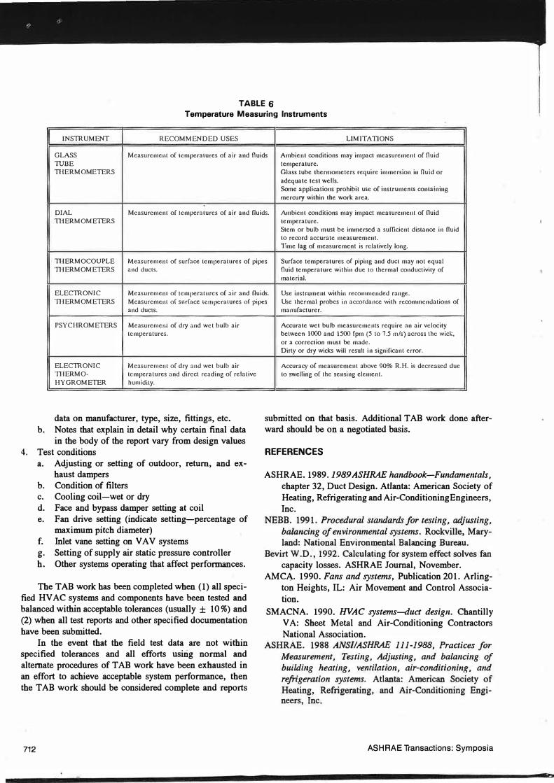
TABLE 6 Temperature Measuring Instruments
INSTRUMENT RECOMMENDED USES LIMITATIONS
GLASS Measurement of Lcmperalures of air and fluids Ambient conditions may impact measurement of fluid TUBE temperature. TI!ERMOMETERS Glass Lube thermometers require immersion in fluid or
adequate test wells. Some applications prohibit use of instruments containing mercury within the work area.
DIAL Measurement of lcmperalures of air and fluids. Ambicnl conditions may impact measurement of fluid 1HERMOMETERS tempera lure.
Stem or bulb must be immersed a sufficient distance in fluid to record accurate measurement. Time Ing of measurement is relatively long.
TI!ERMOCOUPLE Measurement of surface temperatures of pipes Surface temperatures of piping and duel may nol equal llIERMOMETERS and duels. fluid temperature within due Lo thermal conductivily of
material.
ELECTRONIC Measurement of temperatures of air and fluids . Use instr.umenl within recommended range. ll1ERMOMETERS Measurement of surface Lcmperalures of pipes Use thermal probes in accordance with recommendations of
and duels.
PSYCHROMETERS Measurement of dry and wet bulb air temperatures.
ELECTRONIC Measurement of dry and wel bulb air ll1ERMO- temperatures and direct reading of relative HYGROMETER humidity.
data on manufacturer, type, size, fittings, etc. b. Notes that explain in detail why certain final data
in the body of the report vary from design values 4. Test conditions
a. Adjusting or setting of outdoor, return, and ex-haust dampers
b. Condition of filters c. Cooling coil-wet or dry d. Face and bypass damper setting at coil e. Fan drive setting (indicate setting-percentage of
maximum pitch diameter) f. Inlet vane setting on VA V systems g. Setting of supply air static pressure controller h. Other systems operating that affect performances.
The TAB work has been completed when (1) all specified HV AC systems and components have been tested and balanced within acceptable tolerances (usually ± 10%) and (2) when all test reports and other specified documentation have been submitted.
In the event that the field test data are not within specified tolerances and all efforts usirig normal and alternate procedures of TAB work have been exhausted in an effort to achieve acceptable system performance, then the TAB work should be considered complete and reports
712
manufacturer.
Accurate wet bulb measurements require an air velocity between 1000 and 1500 fpm (5 to 7.5 111/s) across the wick, or a correction must be made. Dirty or dry wicks will result in significant error.
Accuracy of measliremenl above 90% R.H. is decreased due lo swelling of the sensing elemenl.
submitted on that basis. Additional TAB work done afterward should be on a negotiated basis.
REFERENCES
ASHRAE. 1989. 1989 ASHRAE handbook-Fundamentals, chapter 32, Duct Design. Atlanta: American Society of Heating, Refrigerating and Air-Conditioning Engineers, Inc.
NEBB. 1991. Procedural standards for testing, adjusting, bala11ci11g of e11vironme11tal systems. Rockville, Maryland: National Environmental Balancing Bureau.
Bevirt W.D. , 1992. Calculating for system effect solves fan capacity losses. ASHRAE Journal, November.
AMC!\.. 1990. Fans and systems, Publication 201. Arlington Heights, IL: Air Movement and Control Association.
SMACNA. 1990. HVAC systems-duct design. Chantilly VA: Sheet Metal and Air-Conditioning Contractors National Association.
ASHRAE. 1988 ANSIIASHRAE 111-1988, Practices for Measurement, Testing, Adjusti11g, and balancing of buildi11g hearing, vemilation, air-conditioni11g, a11d refrigeration systems. Atlanta: American Society of Heating, Refrigerating, and Air-Conditioning Engineers, Inc.
ASHRAE Transactions: Symposia
DISCUSSION
Vin Gupta, Supervisor, 3M, St. Paul, MN: Should the testing and .balancing be done by an independent contractor? Should equal emphasis be placed on air and water systems?
W.D. Bevirt: The National Environmental Balancing Bureau (NEBB) has almost 500 certified firms doing testing, adjusting, and balancing (TAB) work. The NEBB is specified throughout the world by U.S. federal agencies and the AIA, CSI, and most other specifying authorities. As NEBR-certified firms are both independent and nonindependent, it seems that the rigid requirements of integrity, fiscal responsibility, and written and practical examinations required by the NEBB have led to the steady growth of the NEBB and the use of NEBB firms for TAB work regardless of the "independence" question.
Figure 23 in \Chapter 12 of the 1992 ASHRAE Systems and Equipment Handbook shows that a 20°F (11°C) A.t flow of 50% capacity in a hot-water coil provides about 90% heat transfer. The basic problems with hydronic systems, in my experience, are short-circuiting and airlogged systems. Therefore, I believe that most emphasis traditionally is on the air systems TAB.
Morris B. Elovicz, Principal Mechanical Engineer, Metropolitan Water Reclamation District of Greater Chicago, Il...: How would you specify the TAB for a VA V system for a laboratory that has a high number of hoods?
Bevirt: The testing and balancing of laboratory hoods is an area of great debate among experienced professionals, so the introduction of VA V supply air systems adds another variable to this debate. However, the system design engineer must specify all of the airflow parameters. Any welltrained or certified TAB technician can adjust to the design airflows if the systems are capable of furnishing them.
Gary E. Elliott, Mechanical Design Engineer, Group Eight Engineering Ltd., Hamilton, ON, Canada: What is the normal range of cost that a TAB firm charges for a large HY AC project? How do you convince the owner that the work to be done by the commissioning and balancing firm is not covered by the fee paid to the design engineer?
Bevirt: I do not have access to costs. The book Air Conditioning Testing/Adjusting/Balancing, A Field Practice Manual, by John Gladstone, bas chapter 19, "Cost Estimating for Testing and Balancing." This chapter has "manhours" for many TAB operations.
All construction contracts (architectural, engineering, general construction, etc.) should be specific as to what is and what is not included. Then there should not be any questions.
ASH RAE Transactions: Symposia
Joseph F. Auclair, Chief Engineer, Frosty Mechanical, Pittsfield, MA: How can the engineer have confidence in the TAB reports vs. the actual conditions because 90% of the results as noted in the reports cannot be reproduced in the field? Who decides what items are to be filled out on the forms and when?
Bev!rt: Room occupants and in-house maintenance personnel often change air outlet device and damper settings, fan speeds, etc., in an attempt to satisfy the comfort of occupants or changing conditions. However, if a building has not been occupied, TAB readings should be ± 10 % with the HY AC systems operating under the same conditions (i.e., 100% outdoor air, VAY boxes full open, etc.).
Most TAB standard forms contain itemized lines and columns to meet a broad band of all conditions that may be encountered in many types of systems and equipment. They do not and cannot apply to every job situation. However, if an item does not pertain to the system or equipment TAB, a "NIA" should be entered in the space on the form by the TAB supervisor.
Ernest E. Choat, Owner, Environmental Engineering Consultants, Oak Ridge, TN: To ensure satisfactory completion of TAB work, it is not sufficienl for engineers to simply specify that the work shall be done by an NEBBor AABC-certified firm, as was indicated in this paper and N0-94-4-3. Nor is it sufficient to simply specify that work shall be done in accordance with the standards that were cited in this paper, as these are woefully inadequate.
In my view, the design engineer must specify and approve the qualifications of individuals of the TAB team that is to do his or her work to ensure that a qualified team is supplied. The author of N0-94-4-2 discussed this view briefly in the first part of his presentation, but failed to emphasize it to the extent that it deserves.
Bevirt: There is nothing better than a comprehensive, detailed TAB specification with step-by-step procedures written by a system design engineer that includes estimated duct air leakage, any system effect, etc., as long as it is realistic and achievable. There is nothing worse than a specification requiring the TAB firm to use the "best of" NEBB, AABC, ASHRAE, and SMACNA procedures or guidelines! Who can interpret "what is best"? The HV AC industry has been well served by AABC firms using their National Standards for Testing and Balancing Heating, Ventilating, and Air Conditioning Systems and NEBB firms using their Procedural Standards for Testing, Adjusting and Balancing of Environmental Systems.
Gaylon Richardson, Vice-President, Engineered Air Balance, Houston, TX: The presentation included a chart showing duct system leakage rates, and you stated that there
713
is no way to obtain a leakage rate of 1 % or less. The chart is established with certain types of sealing methods (classes 3, 6, etc.) and shows rates greater than 5%. Why do you say there is no way to obtain a leakage rate of 1 % or less in medium- and high-pressure duct systems? There are many specifications that require leakage rates of 1 % or less, and this requirement is being obtained.
Bevirt: I stated that, based on Table 7 in chapter 32 of the 1993 ASHRAE Fundamentals Handbook, the larger the system and the higher the internal duct pressures, the greater the duct leakage will be in any system. Table 7 is based on average workmanship of ductwork prop�rly constructed, sealed, and installed in accordance with the SMACNA HVAC Duct Construction Standards� Metal and Flexible. Average size, medium- and high-pressure· rectangular Leakage Class 6 duct systems (with internal pressures of 2 to 6 in. w.g.) have leakage rates of 1.9% to 9.6%. Under the same conditions, round Leakage Class 3 duct systems have leakage rates of 0. 9 % to 4. 8 % . This is hardly less than 1 % .
However, I agree that, with above-average workmanship, an average-size system of round spiral ductwork with
proprietary joint systems and/or a mastic-tape�type sealing system with joints and fittings a long distance apart, an air leakage rate as low as 0.5 % may be possible.
Also, totally sealing rectangular low-pressure (0.5 to 2.0 in. w.g.) ductwork would not move it from Leakage Class 24 to Leakage Class 6 because the lighter weight construction would allow more leakage than ducts constructed of heavier gauges and reinforcement. Nevertheless, total sealing shou�d decrease the air leakage considerably, a move that I have always supported.
714 ASHRAE Transactions: Symposia