what do we understand about convolutional networks?
TRANSCRIPT

What Do We Understand AboutConvolutional Networks?
Isma Hadji and Richard P. Wildes
Department of Electrical Engineering and Computer Science
York University
Toronto, Ontario
Canada
arX
iv:1
803.
0883
4v1
[cs
.CV
] 2
3 M
ar 2
018

Chapter 1
Introduction
1.1 Motivation
Over the past few years major computer vision research efforts have focused on
convolutional neural networks, commonly referred to as ConvNets or CNNs. These
efforts have resulted in new state-of-the-art performance on a wide range of classifi-
cation (e.g [64,88,139]) and regression (e.g [36,97,159]) tasks. In contrast, while the
history of such approaches can be traced back a number of years (e.g [49, 91]), the-
oretical understanding of how these systems achieve their outstanding results lags.
In fact, currently many contributions in the computer vision field use ConvNets
as a black box that works while having a very vague idea for why it works, which
is very unsatisfactory from a scientific point of view. In particular, there are two
main complementary concerns: (1) For learned aspects (e.g convolutional kernels),
exactly what has been learned? (2) For architecture design aspects (e.g number
of layers, number of kernels/layer, pooling strategy, choice of nonlinearity), why
are some choices better than others? The answers to these questions not only will
improve the scientific understanding of ConvNets, but also increase their practical
applicability.
Moreover, current realizations of ConvNets require massive amounts of data for
training [84, 88, 91] and design decisions made greatly impact performance [23, 77].
Deeper theoretical understanding should lessen dependence on data-driven design.
While empirical studies have investigated the operation of implemented networks, to
1

1.2. Objective 2
date, their results largely have been limited to visualizations of internal processing
to understand what is happening at the different layers of a ConvNet [104,133,154].
1.2 Objective
In response to the above noted state of affairs, this document will review the most
prominent proposals using multilayer convolutional architectures. Importantly, the
various components of a typical convolutional network will be discussed through a
review of different approaches that base their design decisions on biological findings
and/or sound theoretical bases. In addition, the different attempts at understanding
ConvNets via visualizations and empirical studies will be reviewed. The ultimate
goal is to shed light on the role of each layer of processing involved in a ConvNet
architecture, distill what we currently understand about ConvNets and highlight
critical open problems.
1.3 Outline of report
This report is structured as follows: The present chapter has motivated the need for
a review of our understanding of convolutional networks. Chapter 2 will describe
various multilayer networks and present the most successful architectures used in
computer vision applications. Chapter 3 will more specifically focus on each one
of the building blocks of typical convolutional networks and discuss the design of
the different components from both biological and theoretical perspectives. Finally,
chapter 4 will describe the current trends in ConvNet design and efforts towards
ConvNet understanding and highlight some critical outstanding shortcomings that
remain.

Chapter 2
Multilayer Networks
This chapter gives a succinct overview of the most prominent multilayer architectures
used in computer vision, in general. Notably, while this chapter covers the most
important contributions in the literature, it will not to provide a comprehensive
review of such architectures, as such reviews are available elsewhere (e.g . [17, 56,
90]). Instead, the purpose of this chapter is to set the stage for the remainder
of the document and its detailed presentation and discussion of what currently is
understood about convolutional networks applied to visual information processing.
2.1 Multilayer architectures
Prior to the recent success of deep learning-based networks, state-of-the-art com-
puter vision systems for recognition relied on two separate but complementary steps.
First, the input data is transformed via a set of hand designed operations (e.g . con-
volutions with a basis set, local or global encoding methods) to a suitable form.
The transformations that the input incurs usually entail finding a compact and/or
abstract representation of the input data, while injecting several invariances depend-
ing on the task at hand. The goal of this transformation is to change the data in a
way that makes it more amenable to being readily separated by a classifier. Second,
the transformed data is used to train some sort of classifier (e.g . Support Vector
Machines) to recognize the content of the input signal. The performance of any
classifier used is, usually, heavily affected by the used transformations.
3

2.1. Multilayer architectures 4
Multilayer architectures with learning bring about a different outlook on the
problem by proposing to learn, not only the classifier, but also learn the required
transformation operations directly from the data. This form of learning is commonly
referred to as representation learning [7,90], which when used in the context of deep
multilayer architectures is called deep learning.
Multilayer architectures can be defined as computational models that allow for
extracting useful information from the input data multiple levels of abstraction.
Generally, multilayer architectures are designed to amplify important aspects of the
input at higher layers, while becoming more and more robust to less significant
variations. Most multilayer architectures stack simple building block modules with
alternating linear and nonlinear functions. Over the years, a plethora of various mul-
tilayer architectures were proposed and this section will cover the most prominent
such architectures adopted for computer vision applications. In particular, artificial
neural network architectures will be the focus due to their prominence. For the sake
of succinctness, such networks will be referred to more simply as neural networks in
the following.
2.1.1 Neural networks
A typical neural network architecture is made of an input layer, x, an output layer,
y, and a stack of multiple hidden layers, h, where each layer consists of multiple
cells or units, as depicted in Figure 2.1. Usually, each hidden unit, hj, receives input
from all units at the previous layer and is defined as a weighted combination of the
inputs followed by a nonlinearity according to
hj = F (bj +∑i
wijxi) (2.1)
where, wij, are the weights controlling the strength of the connections between the
input units and the hidden unit, bj is a small bias of the hidden unit and F (.) is
some saturating nonlinearity such as the sigmoid.
Deep neural networks can be seen as a modern day instantiation of Rosenblatt’s
perceptron [122] and multilayer perceptron [123]. Although, neural network models

2.1. Multilayer architectures 5
Figure 2.1: Illustration of a typical Neural Network architecture. Figure reproducedfrom [17].
have been around for many years (i.e. since the 1960’s) they were not heavily used
until more recently. There were a number of reasons for this delay. Initial negative
results showing the inability of the perceptron to model simple operations like XOR,
hindered further investigation of perceptrons for a while until their generalizations
to many layers [106]. Also, lack of an appropriate training algorithm slowed progress
until the popularization of the backpropagation algorithm [125]. However, the bigger
roadblock that hampered the progress of multilayer neural networks is the fact that
they rely on a very large number of parameters, which in turn implies the need for
large amounts of training data and computational resources to support learning of
the parameters.
A major contribution that allowed for a big leap of progress in the field of deep
neural networks is layerwise unsupervised pretraining, using Restricted Boltzman
Machine (RBM) [68]. Restricted Boltzman Machines can be seen as two layer neural
networks where, in their restricted form, only feedforward connections are allowed.
In the context of image recognition, the unsupervised learning method used to train
RBMs can be summarized in three steps. First, for each pixel, xi, and starting with
a set of random weights, wij, and biases, bj, the hidden state, hj, of each unit is set
to 1 with probability, pj. The probability is defined as
pj = σ(bj +∑i
xiwij) (2.2)

2.1. Multilayer architectures 6
where, σ(y) = 1/(1+exp(−y)). Second, once all hidden states have been set stochas-
tically based on equation 2.2, an attempt to reconstruct the image is performed by
setting each pixel, xi, to 1 with probability pi = σ(bi+∑
j hjwij). Third, the hidden
units are corrected by updating the weights and biases based on the reconstruction
error given by
∆wij = α(〈xihj〉input − 〈xihj〉reconstruction) (2.3)
where α is a learning rate and 〈xihj〉 is the number of times pixel xi and the hidden
unit hj are on together. The entire process is repeated N times or until the error
drops bellow a pre-set threshold, τ . After one layer is trained its outputs are used
as an input to the next layer in the hierarchy, which is in turn trained following
the same procedure. Usually, after all the network’s layers are pretrained, they are
further finetuned with labeled data via error back propagation using gradient descent
[68]. Using this layerwise unsupervised pretraining allows for training deep neural
networks without requiring large amounts of labeled data because unsupervised
RBM pretraining provides a way for an empirically useful initialization of the various
network parameters.
Neural networks relying on stacked RBMs were first successfully deployed as a
method for dimensionality reduction with an application to face recognition [69],
where they were used as a type of auto-encoder. Loosely speaking, auto-encoders
can be defined as multilayer neural networks that are made of two main parts: First,
an encoder transforms the input data to a feature vector; second, a decoder maps the
generated feature vector back to the input space; see, Figure 2.2. The parameters
of the auto-encoder are learned by minimizing a reconstruction error between the
input and it’s reconstructed version.

2.1. Multilayer architectures 7
Figure 2.2: Structure of a typical Auto-Encoder Network. Figure reproduced from[17].
Beyond RBM based auto-encoders, several types of auto-encoders were later
proposed. Each auto-encoder introduced a different regularization method that
prevents the network from learning trivial solutions even while enforcing different
invariances. Examples include Sparse Auto-Encoders (SAE) [8], Denoising Auto-
Encoders (DAE) [141, 142] and Contractive Auto-Encoders (CAE) [118]. Sparse
Auto-Encoders [8] allow the intermediate representation’s size (i.e. as generated by
the encoder part) to be larger than the input’s size while enforcing sparsity by pe-
nalizing negative outputs. In contrast, Denoising Auto-Encoders [141,142] alter the
objective of the reconstruction itself by trying to reconstruct a clean input from an
artificially corrupted version, with the goal being to learn a robust representation.
Similarly, Contractive Auto-Encoders [118] build on denoising auto-encoders by fur-
ther penalizing the units that are most sensitive to the injected noise. More detailed
reviews of various types of auto-encoders can be found elsewhere [7].
2.1.2 Recurrent neural networks
When considering tasks that rely on sequential inputs, one of the most successful
multilayer architectures is the Recurrent Neural Network (RNN) [9]. RNNs, illus-
trated in Figure 2.3, can be seen as a special type of neural network where each
hidden unit takes input from the the data it observes at the current time step as
well as its state at a previous time step. The output of an RNN is defined as
ht = σ(wixt + uiht−1) (2.4)

2.1. Multilayer architectures 8
Figure 2.3: Illustration of the operations of a standard Recurrent Neural Network.Each RNN unit takes new input at the current time frame, xt, and from a previoustime step, ht−1 and the new output of the unit is calculated according to (2.4) andcan be fed to another layer of processing in a multilayer RNN.
where σ is some nonlinear squashing function and wi and ui are the network param-
eters that control the relative importance of the present and past information.
Although RNNs are seemingly powerful architectures, one of their major prob-
lems is their limited ability to model long term dependencies. This limitation is
attributed to training difficulties due to exploding or vanishing gradient that can
occur when propagating the error back through multiple time steps [9]. In partic-
ular, during training the back propagated gradient is multiplied with the network’s
weights from the current time step all the way back to the initial time step. There-
fore, because of this multiplicative accumulation, the weights can have a non-trivial
effect on the propagated gradient. If weights are small the gradient vanishes, whereas
larger weights lead to a gradient that explodes. To correct for this difficulty, Long
Short Term Memories (LSTM) were introduced [70].
LSTMs are recurrent networks that are further equipped with a storage or mem-
ory component, illustrated in Figure 2.4, that accumulates information over time.
An LSTM’s memory cell is gated such that it allows information to be read from it
or written to it. Notably, LSTMs also contain a forget gate that allows the network
to erase information when it is not needed anymore. LSTMs are controlled by three
different gates (the input gate, it, the forget gate, ft, and the output gate, ot), as
well as the memory cell state, ct. The input gate is controlled by the current input,
xt, and the previous state, ht−1, and it is defined as

2.1. Multilayer architectures 9
it = σ(wixt + uiht−1 + bi), (2.5)
where, wi, ui, bi represent the weights and bias controlling the connections to the
input gate and σ is usually a sigmoid function. The forget gate is similarly defined
as
ft = σ(wfxt + ufht−1 + bf ), (2.6)
and it is controlled by its corresponding weights and bias, wf , uf , bf . Arguably, the
most important aspect of an LSTM is that it copes with the challenge of vanishing
and exploding gradients. This ability is achieved through additive combination of
the forget and input gate states in determining the memory cell’s state, which, in
turn, controls whether information is passed on to another cell via the output gate.
Specifically, the cell state is computed in two steps. First, a candidate cell state is
estimated according to
gt = φ(wcxt + ucht−1 + bc), (2.7)
where φ is usually a hyperbolic tangent. Second, the final cell state is finally con-
trolled by the current estimated cell state, gt, and the previous cell state, ct−1,
modulated by the input and forget gate according to
ct = itgt + ftct−1. (2.8)
Finally, using the cell’s state and the current and previous inputs, the value of the
output gate and the output of the LSTM cell are estimated according to
ot = σ(woxt + uoht−1 + bo), (2.9)
where
ht = φ(ct) ot. (2.10)

2.1. Multilayer architectures 10
Figure 2.4: Illustration of a typical LSTM unit. The unit takes input at the currenttime, xt, and from a previous time, ht−1, and it returns an output to be fed into thenext time, ht. The final output of the LSTM unit is controlled by the input gate,it, the forget gate, ft, and the output gate, ot, as well as the memory cell state, ct,which are defined in (2.5), (2.6), (2.9) and (2.8), respectively. Figure reproducedfrom [33].
2.1.3 Convolutional networks
Convolutional networks (ConvNets) are a special type of neural network that are
especially well adapted to computer vision applications because of their ability to hi-
erarchically abstract representations with local operations. There are two key design
ideas driving the success of convolutional architectures in computer vision. First,
ConvNets take advantage of the 2D structure of images and the fact that pixels
within a neighborhood are usually highly correlated. Therefore, ConvNets eschew
the use of one-to-one connections between all pixel units (i.e. as is the case of most
neural networks) in favor of using grouped local connections. Further, ConvNet
architectures rely on feature sharing and each channel (or output feature map) is
thereby generated from convolution with the same filter at all locations as depicted
in Figure 2.5. This important characteristic of ConvNets leads to an architecture
that relies on far fewer parameters compared to standard Neural Networks. Second,
ConvNets also introduce a pooling step that provides a degree of translation invari-
ance making the architecture less affected by small variations in position. Notably,
pooling also allows the network to gradually see larger portions of the input thanks
to an increased size of the network’s receptive field. The increase in receptive field
size (coupled with a decrease in the input’s resolution) allows the network to repre-

2.1. Multilayer architectures 11
sent more abstract characteristics of the input as the network’s depth increase. For
example, for the task of object recognition, it is advocated that ConvNets layers
start by focusing on edges to parts of the object to finally cover the entire object at
higher layers in the hierarchy.
Figure 2.5: Illustration of the structure of a standard Convolutional Network. Figurereproduced from [93].
The architecture of convolutional networks is heavily inspired by the processing
that takes place in the visual cortex as described in the seminal work of Hubel and
Wiesel [74] (further discussed in Chapter 3). In fact, it appears that the earliest in-
stantiation of Convolutional Networks is Fukushima’s Neocognitron [49], which also
relied on local connections and in which each feature map responds maximally to
only a specific feature type. The Neocognitron is composed of a cascade of K layers
where each layer alternates S-cell units, Usl, and complex cell units, Ucl, that loosely
mimic the processing that takes place in the biological simple and complex cells,
respectively, as depicted in Figure 2.6. The simple cell units perform operations
similar to local convolutions followed by a Rectified Linear Unit (ReLU) nonlin-
earity, ϕ(x) =
x; if x ≥ 0
0; x < 0,while the complex cells perform operations similar
to average pooling. The model also included a divisive nonlinearity to accomplish
something akin to normalization in contemporary ConvNets.

2.1. Multilayer architectures 12
Figure 2.6: Illustration of the structure of the Neocognitron. Figure reproducedfrom [49].
As opposed to most standard ConvNet architectures (e.g . [88,91]) the Neocogni-
tron does not need labeled data for learning as it is designed based on self organizing
maps that learn the local connections between consecutive layers via repetitive pre-
sentations of a set of stimulus images. In particular, the Neocognitron is trained to
learn the connections between an input feature map and a simple cell layer (con-
nections between a simple cells layer and complex cells layer are pre-fixed) and the
learning procedure can be broadly summarized in two steps. First, each time a new
stimulus is presented at the the input, the simple cells that respond to it maximally
are chosen as a representative cell for that stimulus type. Second, the connections
between the input and those representative cells are reinforced each time they re-
spond to the same input type. Notably, simple cells layers are organized in different
groups or planes such that each plane responds only to one stimulus type (i.e. similar
to feature maps in a modern ConvNet architecture). Subsequent extensions to the
Neocognitron included allowances for supervised learning [51] as well as top-down
attentional mechanisms [50].
Most ConvNets architectures deployed in recent computer vision applications
are inspired by the successful architecture proposed by LeCun in 1998, now known
as LeNet, for handwriting recognition [91]. As described in key literature [77, 93],
a classical convolutional network is made of four basic layers of processing: (i)
a convolution layer, (ii) a nonlinearity or rectification layer, (iii) a normalization

2.1. Multilayer architectures 13
layer and (iv) a pooling layer. As noted above, these components were largely
present in the Neocognitron. A key addition in LeNet was the incorporation of back
propagation for relatively efficient learning of the convolutional parameters.
Although, ConvNets allow for an optimized architecture that requires far fewer
parameters compared to their fully connected neural network counterpart, their main
shortcoming remains their heavy reliance on learning and labeled data. This data
dependence is probably one of the main reasons why ConvNets were not widely used
until 2012 when the availability of the large ImageNet dataset [126] and concomitant
computational resources made it possible to revive interest in ConvNets [88]. The
success of ConvNets on ImageNet led to a spurt of various ConvNet architectures
and most contributions in this field are merely based on different variations of the
basic building blocks of ConvNets, as will be discussed later in Section 2.2.
2.1.4 Generative adversarial networks
Generative Adversarial Networks (GANs) are relatively new models taking advan-
tage of the strong representational power of multilayer architectures. GANs were
first introduced in 2014 [57] and although they did not present a different archi-
tecture per se (i.e. in terms of novel network building blocks for example), they
entail some peculiarities, which make them a slightly different class of multilayer
architectures. A key challenge being responded to by GANs is the introduction of
an unsupervised learning approach that requires no labeled data.
A typical GAN is made of two competing blocks or sub-networks, as shown in
Figure 2.7; a generator network, G(z; θg), and a discriminator network, D(x; θd),
where z is input random noise, x is real input data (e.g . an image) and θg and
θd are the parameters of the two blocks, respectively. Each block can be made of
any of the previously defined multilayer architectures. In the original paper both
the generator and discriminator were multilayer fully connected networks. The
discriminator, D, is trained to recognize the data coming from the generator and
assigning the label “fake” with probability pd while assigning the label “real” to
true input data with probability 1 − pd. In complement, the generator network is
optimized to generate fake representations capable of fooling the discriminator. The

2.1. Multilayer architectures 14
Figure 2.7: Illustration of the structure of a general purpose Generative AdverserialNetwork (GAN).
two blocks are trained alternately in several steps where the ideal outcome of the
training process is a discriminator that assigns a probability of 50% to both real
and fake data. In other words, after convergence the generator should be able to
generate realistic data from random input.
Since the original paper, many contributions participated in enhancing the capa-
bilities of GANs via use of more powerful multilayer architectures as the backbones
of the network [114] (e.g . pretrained convolutional networks for the discriminator
and deconvolutional networks, that learn upsampling filters for the generator). Some
of the successful applications of GANs include: text to image synthesis (where the
input to the network is a textual description of the image to be rendered [115]),
image super resolution where the GAN generates a realistic high resolution image
from a lower resolution input [94], image inpainting where the role of GANs is to fill
holes of missing information from an input image [149] and texture synthesis where
GANs are used to synthesize realistic textures from input noise [10].
2.1.5 Multilayer network training
As discussed in the previous sections, the success of the various multilayer architec-
tures largely depends on the success of their learning process. While neural networks
usually rely on an unsupervised pretraining step first, as described in Section 2.1.1,
they are usually followed by the most widely used training strategy for multilayer
architectures, which is fully supervised. The training procedure is usually based on
2.1. Multilayer architectures 15
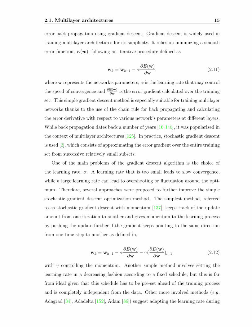
error back propagation using gradient descent. Gradient descent is widely used in
training multilayer architectures for its simplicity. It relies on minimizing a smooth
error function, E(w), following an iterative procedure defined as
wk = wk−1 − α∂E(w)
∂w, (2.11)
where w represents the network’s parameters, α is the learning rate that may control
the speed of convergence and ∂E(w)∂w
is the error gradient calculated over the training
set. This simple gradient descent method is especially suitable for training multilayer
networks thanks to the use of the chain rule for back propagating and calculating
the error derivative with respect to various network’s parameters at different layers.
While back propagation dates back a number of years [16,146], it was popularized in
the context of multilayer architectures [125]. In practice, stochastic gradient descent
is used [2], which consists of approximating the error gradient over the entire training
set from successive relatively small subsets.
One of the main problems of the gradient descent algorithm is the choice of
the learning rate, α. A learning rate that is too small leads to slow convergence,
while a large learning rate can lead to overshooting or fluctuation around the opti-
mum. Therefore, several approaches were proposed to further improve the simple
stochastic gradient descent optimization method. The simplest method, referred
to as stochastic gradient descent with momentum [137], keeps track of the update
amount from one iteration to another and gives momentum to the learning process
by pushing the update further if the gradient keeps pointing to the same direction
from one time step to another as defined in,
wk = wk−1 − α∂E(w)
∂w− γ(
∂E(w)
∂w)t−1, (2.12)
with γ controlling the momentum. Another simple method involves setting the
learning rate in a decreasing fashion according to a fixed schedule, but this is far
from ideal given that this schedule has to be pre-set ahead of the training process
and is completely independent from the data. Other more involved methods (e.g .
Adagrad [34], Adadelta [152], Adam [86]) suggest adapting the learning rate during

2.1. Multilayer architectures 16
training to each parameter, wi, being updated, by performing smaller updates on
frequently changing parameters and larger updates on infrequent ones. A detailed
comparison between the different versions of these algorithms can be found elsewhere
[124].
The major shortcoming of training using gradient descent, as well as its variants,
is the need for large amounts of labeled data. One way to deal with this difficulty is
to resort to unsupervised learning. A popular unsupervised method used in training
some shallow ConvNet architectures is based on the Predictive Sparse Decomposition
(PSD) method [85]. Predictive Sparse Decomposition learns an overcomplete set
of filters whose combination can be used to reconstruct an image. This method
is especially suitable for learning the parameters of a convolutional architecture,
as the algorithm is designed to learn basis functions that reconstruct an image
patchwise. Specifically, Predictive Sparse Decomposition (PSD) builds on sparse
coding algorithms that attempts to find an efficient representation, Y, of an input
signal, X, via a linear combination with a basis set, B. Formally, the problem of
sparse coding is broadly formulated as a minimization problem defined as,
L(X, Y ;B) = ||X −BY ||22. (2.13)
PSD adapts the idea of sparse coding in a convolutional framework by minimizing
a reconstruction error defined as,
L(X, Y ;B) = ||X −BY ||22 + λ||Y ||1 + α||Y − F (X;G,W,D)||22 (2.14)
where F (X;G,W,D) = G tanh(WX+D) and W , D and G are weights, biases and
gains (or normalization factors ) of the network, respectively. By minimizing the
loss function defined in equation 2.14, the algorithm learns a representation, Y , that
reconstructs the input patch, X, while being similar to the predicted representation
F . The learned representation will also be sparse owing to the second term of
the equation. In practice, the error is minimized in two alternating steps where
parameters, (B,G,W,D), are fixed and minimization is performed over Y . Then,

2.1. Multilayer architectures 17
the representation Y is fixed while minimizing over the other parameters. Notably,
PSD is applied in a patchwise procedure where each set of parameters, (G,W,D), is
learned from the reconstruction of a different patch from an input image. In other
words, a different set of kernels is learned by focusing the reconstruction on different
parts of the input images.
2.1.6 A word on transfer learning
One of the unexpected benefits of training multilayer architecture is the surprising
adaptability of the learned features across different datasets and even different tasks.
Examples include using networks trained with ImageNet for recognition on: other
object recognition datasets such as Caltech-101 [38] (e.g . [96, 154]), other recogni-
tions tasks such as texture recognition (e.g . [25]), other applications such as object
detection (e.g . [53]) and even to video based tasks, such as video action recognition
(e.g . [41, 134,144]).
The adaptability of features extracted with multilayer architectures across dif-
ferent datasets and tasks, can be attributed to their hierarchical nature where the
representations progress from being simple and local to abstract and global. Thus,
features extracted at lower levels of the hierarchy tend to be common across different
tasks thereby making multilayer architectures more amenable to transfer learning.
A systematic exploration of the intriguing transferability of features across dif-
ferent networks and tasks revealed several good practices to take into account in
consideration of transfer learning [150]. First, it was shown that fine tuning higher
layers only, led to systematically better performance when compared to fine tuning
the entire network. Second, this research demonstrated that the more different the
tasks are the less efficient transfer learning becomes. Third, and more surprisingly,
it was found that even after fine tuning the network’s performance under the initial
task is not particularly hampered.
Recently, several emerging efforts attempt to enforce a networks’ transfer learning
capabilities even further by casting the learning problem as a sequential two step
procedure, e.g . [3, 127]. First, a so called rapid learning step is performed where
a network is optimized for a specific task as is usually done. Second, the network
2.2. Spatial convolutional networks 18
parameters are further updated in a global learning step that attempts to minimize
an error across different tasks.
2.2 Spatial convolutional networks
In theory, convolutional networks can be applied to data of arbitrary dimensions.
Their two dimensional instantiations are well suited to the structure of single images
and therefore have received considerable attention in computer vision. With the
availability of large scale datasets and powerful computers for training, the vision
community has recently seen a surge in the use of ConvNets for various applications.
This section describes the most prominent 2D ConvNet architectures that introduced
relatively novel components to the original LeNet described in Section 2.1.3.
2.2.1 Key architectures in the recent evolution of ConvNets
The work that rekindled interest in ConvNet architectures was Krishevsky’s AlexNet
[88]. AlexNet was able to achieve record breaking object recognition results on the
ImageNet dataset. It consisted of eight layers in total, 5 convolutional and 3 fully
connected, as depicted in Figure 2.8.
AlexNet introduced several architectural design decisions that allowed for effi-
cient training of the network using standard stochastic gradient descent. In particu-
lar, four important contributions were key to the success of AlexNet. First, AlexNet
considered the use of the ReLU nonlinearity instead of the saturating nonlinearites,
such as sigmoids, that were used in previous state-of-the-art ConvNet architectures
(e.g . LeNet [91]). The use of the ReLU diminished the problem of vanishing gradient
and led to faster training. Second, noting the fact that the last fully connected layers
in a network contain the largest number of parameters, AlexNet used dropout, first
introduced in the context of neural networks [136], to reduce the problem of over-
fitting. Dropout, as implemented in AlexNet, consists in randomly dropping (i.e.
setting to zero) a given percentage of a layer’s parameters. This technique allows
for training a slightly different architecture at each pass and artificially reducing
the number of parameters to be learned at each pass, which ultimately helps break

2.2. Spatial convolutional networks 19
correlations between units and thereby combats overfitting. Third, AlexNet relied
on data augmentation to improve the network’s ability to learn invariant represen-
tations. For example, the network was trained not only on the original images in
the training set, but also on variations generated by randomly shifting and reflecting
the training images. Finally, AlexNet also relied on several techniques to make the
training process converge faster, such as the use momentum and a scheduled learn-
ing rate decrease whereby the learning rate is decreased every time the learning
stagnates.
Figure 2.8: AlexNet architecture. Notably, although the depiction suggests a twostream architecture, it was in fact a single stream architecture and this depictiononly reflects the fact that AlexNet was trained in parallel on 2 different GPUs.Figure reproduced from [88].
The advent of AlexNet led to a spurt in the number of papers trying to under-
stand what the network is learning either via visualization, as done in the so called
DeConvNet [154], or via systematic explorations of various architectures [22, 23].
One of the direct results of these explorations was the realization that deeper net-
works can achieve even better results as first demonstrated in the 19 layer deep
VGG-Net [135]. VGG-Net achieves its depth by simply stacking more layers while
following the standard practices introduced with AlexNet (e.g . reliance on the ReLU
nonlinearity and data augmentation techniques for better training). The main nov-
elty presented in VGG-Net was the use of filters with smaller spatial extent (i.e.
3× 3 filters throughout the network instead of e.g . 11× 11 filters used in AlexNet),
which allowed for an increase in depth without dramatically increasing the number
of parameters that the network needs to learn. Notably, while using smaller filters,
VGG-Net required far more filters per layer.

2.2. Spatial convolutional networks 20
VGG-Net was the first and simplest of many deep ConvNet architectures that
followed AlexNet. A deeper architecture, commonly known as GoogLeNet, with 22
layers was proposed later [138]. While being deeper than VGG-Net, GoogLeNet
requires far fewer parameters thanks to the use of the so called inception module,
shown in Figure 2.9(a), as a building block. In an inception module convolution
operations at various scales and spatial pooling happen in parallel. The module
is also augmented with 1 × 1 convolutions (i.e. cross-channel pooling) that serve
the purpose of dimensionality reduction to avoid or attenuate redundant filters,
while keeping the network’s size manageable. This cross-channel pooling idea was
motivated by the findings of a previous work known as the Network in Network
(NiN) [96], which disucssed the large redundancies in the learned networks. Stacking
many inception modules led to the now widely used GoogLeNet architecture depicted
in Figure 2.9(b).
(a)
(b)
Figure 2.9: GoogLeNet architecture. (a) A typical inception module showing op-erations that happen sequentially and in parallel. (b) Illustration of a typical “in-ception” architecture that consists of stacking many inception modules. Figurereproduced from [138]
GoogLeNet was the first network to stray away from the strategy of simply
stacking convolutional and pooling layers and it was soon followed by one of the
deepest architectures to date, known as ResNet [64], that also proposed a novel

2.2. Spatial convolutional networks 21
architecture with over 150 layers. ResNet stands for Residual Network where the
main contribution lies in its reliance on residual learning. In particular, ResNet is
built such that each layer learns an incremental transformation, F (x), on top of the
input, x, according to
H(x) = F (x) + x, (2.15)
instead of learning the transformation H(x) directly as done in other standard Con-
vNet architectures. This residual learning is achieved via use of skip connections,
illustrated in Figure 2.10(a), that connect components of different layers with an
identity mapping. Direct propagation of the signal, x, combats the vanishing gradi-
ent problem during back propagation and thereby enables the training of very deep
architectures.
(a)
(b)
Figure 2.10: ResNet architecture. (a) A residual module. (b) Illustration of atypical ResNet architecture that consists of stacking many residual modules. Figurereproduced from [64].
A recent, closely related network building on the success of ResNet is the so
called DenseNet [72], which pushes the idea of residual connections even further. In
DenseNet, every layer is connected, via skip connections, to all subsequent layers of
a dense block as illustrated in Figure 2.11. Specifically, a dense block connects all
layers with feature maps of the same size (i.e. blocks between spatial pooling layers).
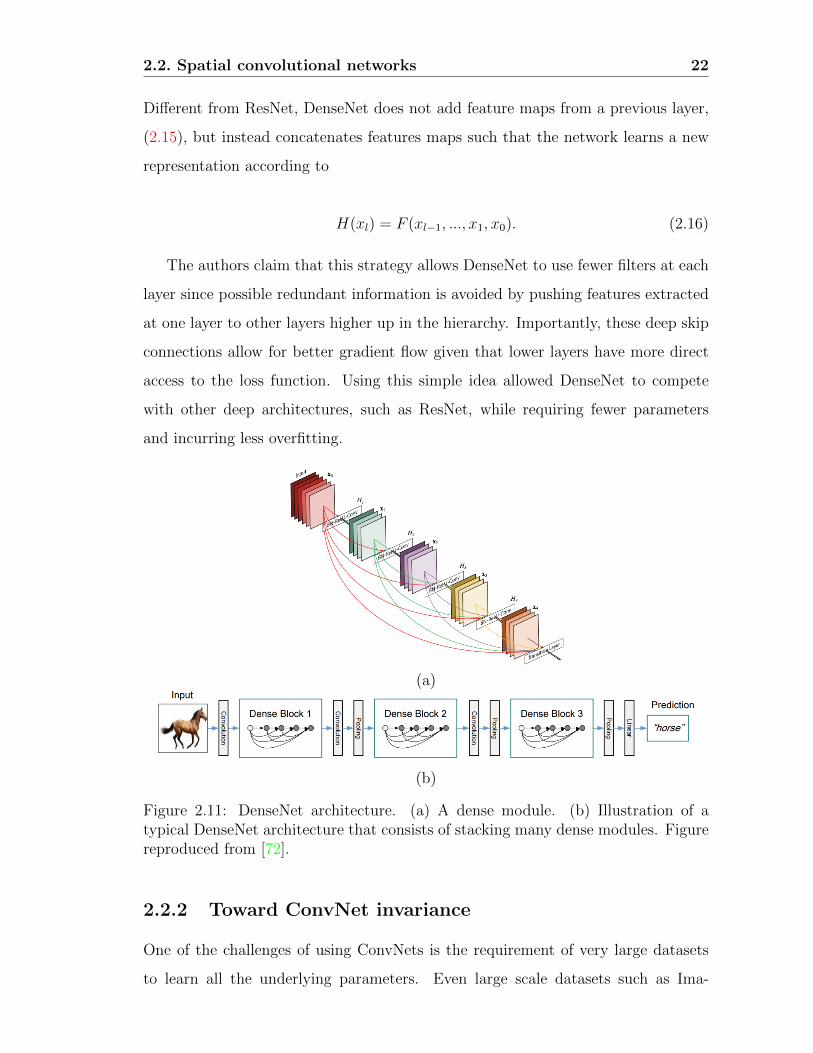
2.2. Spatial convolutional networks 22
Different from ResNet, DenseNet does not add feature maps from a previous layer,
(2.15), but instead concatenates features maps such that the network learns a new
representation according to
H(xl) = F (xl−1, ..., x1, x0). (2.16)
The authors claim that this strategy allows DenseNet to use fewer filters at each
layer since possible redundant information is avoided by pushing features extracted
at one layer to other layers higher up in the hierarchy. Importantly, these deep skip
connections allow for better gradient flow given that lower layers have more direct
access to the loss function. Using this simple idea allowed DenseNet to compete
with other deep architectures, such as ResNet, while requiring fewer parameters
and incurring less overfitting.
(a)
(b)
Figure 2.11: DenseNet architecture. (a) A dense module. (b) Illustration of atypical DenseNet architecture that consists of stacking many dense modules. Figurereproduced from [72].
2.2.2 Toward ConvNet invariance
One of the challenges of using ConvNets is the requirement of very large datasets
to learn all the underlying parameters. Even large scale datasets such as Ima-

2.2. Spatial convolutional networks 23
geNet [126], with over a million images, is considered too small for training certain
deep architectures. One way to cope with the large dataset requirement is to ar-
tificially augment the dataset by altering the images via random flipping, rotation
and jittering, for example. The major advantage of these augmentations is that
the resulting networks become more invariant to various transformations. In fact,
this technique was one of the main reasons behind the large success of AlexNet.
Therefore, beyond methods altering the network’s architecture for easier training,
as discussed in the previous section, other work aims at introducing novel building
blocks that yield better training. Specifically, networks discussed under this section
introduce novel blocks that incorporate learning invariant representation directly
from the raw data.
A prominent ConvNet that explicitly tackles invariance maximization is the Spa-
tial Transformer Network (STN) [76]. In particular, this network makes use of a
novel learned module that increased invariance to unimportant spatial transforma-
tions, e.g . those that result from varying viewpoint during object recognition. The
module is comprised of three submodules: A localization net, a grid generator and a
sampler, as shown in Figure 2.12(a). The operations performed can be summarized
in three steps. First, the localization net, which is usually a small 2 layer neural
network, takes a feature map, U , as input and learns transformation parameters, θ,
from this input. For example, the transformation, Tθ, can be defined as a general
affine transformation allowing the network to learn translations, scalings, rotations
and shears. Second, given the transformation parameters and an output grid of
pre-defined size, H ×W , the grid generator calculates for each output coordinate,
(xti, yti), the corresponding coordinates, (xsi , y
si ), that should be sampled from the
input, U , according to
xsi
ysi
=
θ11 θ12 θ13
θ21 θ22 θ23
xti
yti
1
. (2.17)
Finally, the sampler takes the feature map, U , and the sampled grid and interpolates
the pixels values, (xsi , ysi ), to populate the output feature map, V , at locations (xti, y
ti)
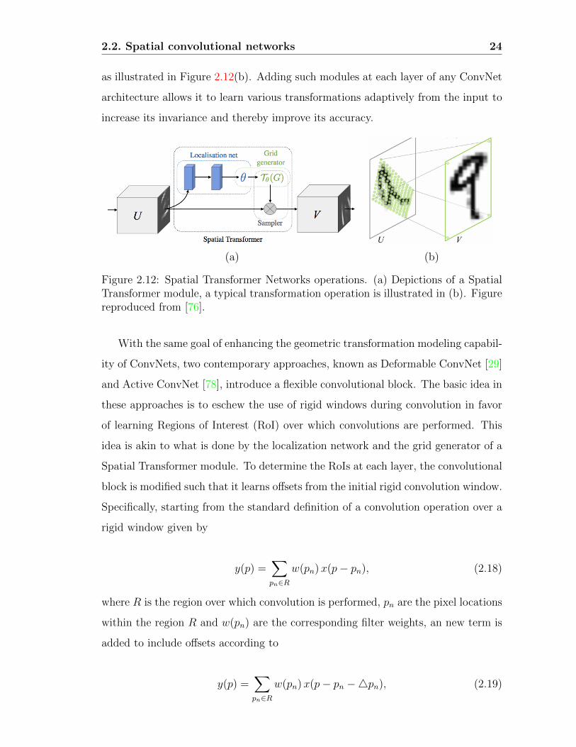
2.2. Spatial convolutional networks 24
as illustrated in Figure 2.12(b). Adding such modules at each layer of any ConvNet
architecture allows it to learn various transformations adaptively from the input to
increase its invariance and thereby improve its accuracy.
(a) (b)
Figure 2.12: Spatial Transformer Networks operations. (a) Depictions of a SpatialTransformer module, a typical transformation operation is illustrated in (b). Figurereproduced from [76].
With the same goal of enhancing the geometric transformation modeling capabil-
ity of ConvNets, two contemporary approaches, known as Deformable ConvNet [29]
and Active ConvNet [78], introduce a flexible convolutional block. The basic idea in
these approaches is to eschew the use of rigid windows during convolution in favor
of learning Regions of Interest (RoI) over which convolutions are performed. This
idea is akin to what is done by the localization network and the grid generator of a
Spatial Transformer module. To determine the RoIs at each layer, the convolutional
block is modified such that it learns offsets from the initial rigid convolution window.
Specifically, starting from the standard definition of a convolution operation over a
rigid window given by
y(p) =∑pn∈R
w(pn)x(p− pn), (2.18)
where R is the region over which convolution is performed, pn are the pixel locations
within the region R and w(pn) are the corresponding filter weights, an new term is
added to include offsets according to
y(p) =∑pn∈R
w(pn)x(p− pn −4pn), (2.19)
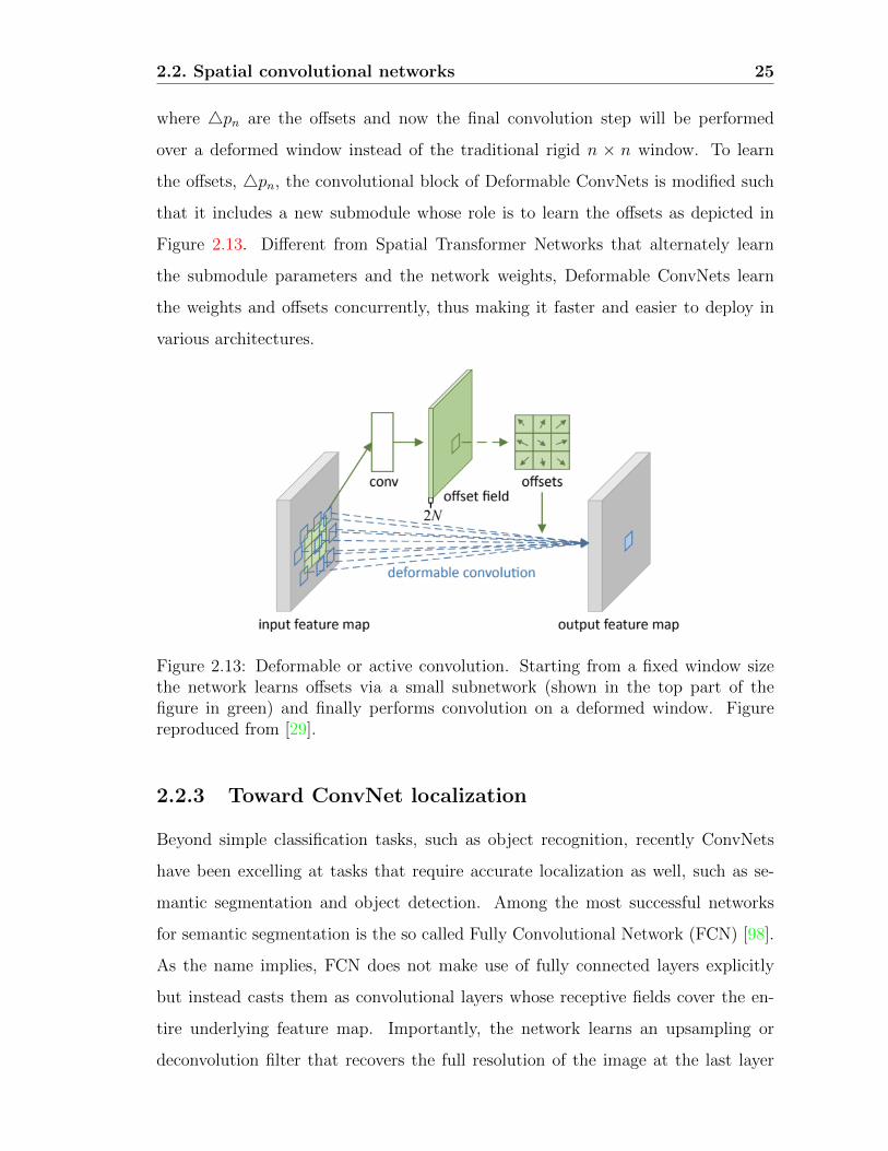
2.2. Spatial convolutional networks 25
where 4pn are the offsets and now the final convolution step will be performed
over a deformed window instead of the traditional rigid n × n window. To learn
the offsets, 4pn, the convolutional block of Deformable ConvNets is modified such
that it includes a new submodule whose role is to learn the offsets as depicted in
Figure 2.13. Different from Spatial Transformer Networks that alternately learn
the submodule parameters and the network weights, Deformable ConvNets learn
the weights and offsets concurrently, thus making it faster and easier to deploy in
various architectures.
Figure 2.13: Deformable or active convolution. Starting from a fixed window sizethe network learns offsets via a small subnetwork (shown in the top part of thefigure in green) and finally performs convolution on a deformed window. Figurereproduced from [29].
2.2.3 Toward ConvNet localization
Beyond simple classification tasks, such as object recognition, recently ConvNets
have been excelling at tasks that require accurate localization as well, such as se-
mantic segmentation and object detection. Among the most successful networks
for semantic segmentation is the so called Fully Convolutional Network (FCN) [98].
As the name implies, FCN does not make use of fully connected layers explicitly
but instead casts them as convolutional layers whose receptive fields cover the en-
tire underlying feature map. Importantly, the network learns an upsampling or
deconvolution filter that recovers the full resolution of the image at the last layer

2.2. Spatial convolutional networks 26
as depicted in Figure 2.14. In FCN, the segmentation is achieved by casting the
problem as a dense pixelwise classification. In other words, a softmax layer is at-
tached to each pixel and segmentation is achieved by grouping pixels that belong to
the same class. Notably, it was reported in this work that using features from lower
layers of the architecture in the upsampling step plays an important role. It allowed
for more accurate segmentation given that lower layer features tend to capture finer
grained details, which are far more important for a segmentation task compared
to classification. An alternative to learning a deconvolution filter, relies on using
atrou or dilated convolutions [24], i.e. upsampled sparse filters, which helps recov-
ering higher resolution feature maps while keeping the number of parameters to be
learned manageable.
Figure 2.14: Fully Convolutional Network. After upsampling to recover the imagefull resolution at the last layer, each pixel is classified using a softmax to finallygenerate the segments. Figure reproduced from [98].
When it comes to object localization, one of the earliest approaches within the
ConvNet framework is known as Region CNN or R-CNN. This network combined
a region proposal method with a ConvNet architecture [53]. Although R-CNN was
built around simple ideas, it yielded state-of-the-art object detection results. In
particular, R-CNN first uses an off-the-shelf algorithm for region proposals (e.g .
selective search [140]) to detect potential regions that may contain an object. These
regions are then warped to match the default input size of the employed ConvNet
and fed into a ConvNet for feature extraction. Finally, each region’s features are
classified with an SVM and refined in a post processing step via non-maximum
suppression.
In its naive version, R-CNN simply used ConvNets as a feature extractor. How-
ever, its ground breaking results led to improvements that take more advantage

2.2. Spatial convolutional networks 27
of ConvNets’ powerful representation. Examples include, Fast R-CNN [52], Faster
R-CNN [116] and Mask R-CNN [61]. Fast R-CNN, proposes propagating the inde-
pendently computed region proposals through the network to extract their corre-
sponding regions in the last feature map layer. This technique, avoids costly passes
through the network for each region extracted from the image. In addition, Fast
R-CNN avoids heavy post-processing steps by changing the last layer of the net-
work such that it learns both object classes and refined bounding box coordinates.
Importantly, in both R-CNN and Fast R-CNN the detection bottleneck lies in the
region proposal step that is done outside of the ConvNet paradigm.
Faster R-CNN pushes the use of ConvNets even further by adding a sub-module
(or sub-network), called Region Proposal Network (RPN), after the last convolu-
tional layer of a ConvNet. An RPN module enables the network to learn the region
proposals as part of the network optimization. Specifically, RPN is designed as
a small ConvNet consisting of a convolutional layer and a small fully connected
layer and two outputs that return potential object positions and objectness scores
(i.e. probability of belonging to an object class). The entire network’s training is
achieved following an iterative two step procedure. First, the network is optimized
for region proposal extraction using the RPN unit. Second, keeping the extracted
region proposals fixed, the network is finetuned for object classification and final
object bounding box position. More recently, mask R-CNN was introduced to aug-
ment faster R-CNN with the ability to segment the detected regions yielding tight
masks around the detected objects. To this end, mask R-CNN adds a segmentation
branch to the classification and bounding box regression branches of faster R-CNN.
In particular, the new branch is implemented as a small FCN that is optimized for
classifying pixels in any bounding box to one of two classes; foreground or back-
ground. Figure 2.15 illustrates the differences and progress from simple R-CNN to
mask R-CNN.

2.3. Spatiotemporal convolutional networks 28
(a) (b)
(c) (d)
Figure 2.15: Progress of prominent region proposal networks. (a) Structure ofthe original R-CNN. Figure reproduced from [53]. (b) Structure of Fast R-CNN.Figure reproduced from [52]. (c) Structure of Faster R-CNN. Figure reproducedfrom [116].(d) Structure of Mask R-CNN. Figure reproduced from [61].
2.3 Spatiotemporal convolutional networks
The significant performance boost brought to various image based applications via
use of ConvNets, as discussed in Section 2.2, sparked interest in extending 2D spatial
ConvNets to 3D spatiotemporal ConvNets for video analysis. Generally, the various
spatiotemporal architectures proposed in the literature have simply tried to extend
2D architectures from the spatial domain, (x, y), into the temporal domain, (x, y, t).
In the realm of training based spatiotemporal ConvNets, there are three different
architectural design decisions that stand out: LSTM based (e.g . [33,112]), 3D (e.g .
[84,139]) and Two-Stream ConvNets (e.g . [43,134]), which will be described in this
section.
2.3.1 LSTM based spatiotemporal ConvNet
LSTM based spatiotemporal ConvNets, e.g . [33, 112], were some of the early at-
tempts to extend 2D networks to spacetime processing. Their operations can be
summarized in three steps as shown in Figure 2.16. First, each frame is processed
with a 2D network and feature vectors are extracted from their last layer. Second,
these features, from different time steps, are then used as input to LSTMs that

2.3. Spatiotemporal convolutional networks 29
produce temporal outcomes, yt. Third, these outcomes are then either averaged or
linearly combined and passed to a softmax classifier for final prediction.
Figure 2.16: Sample LSTM based spatiotemporal ConvNet. In this network theinput consists of consecutive frames from a video stream. Figure reproduced from[33].
The goal of LSTM based ConvNets is to progressively integrate temporal infor-
mation while not being restricted to a strict input size (temporally). One of the
benefits of such an architecture is equipping the network with the ability to pro-
duce variable size text descriptions (i.e. a task at which LSTMs excel), as done
in [33]. However, while LSTMs can capture global motion relationships, they may
fail at capturing finer grained motion patterns. In addition, these models are usually
larger, need more data and are therefore hard to train. To date, excepting cases
where video and text analysis are being integrated (e.g . [33]), LSTMs generally have
seen limited success in spatiotemporal image analysis.
2.3.2 3D ConvNet
The second prominent type of spatiotemporal networks provides the most straight-
forward generalization of standard 2D ConvNet processing to image spacetime. It
works directly with temporal streams of RGB images and operates on these im-
ages via application of learned 3D, (x, y, t), convolutional filters. Some of the early
attempts at this form of generalization use filters that extend into the temporal
domain with very shallow networks [80] or only at the first convolutional layer [84].

2.3. Spatiotemporal convolutional networks 30
When using 3D convolutions at the first layer only, small tap spatiotemporal filters
are applied on each 3 or 4 consecutive frames. To capture longer range motions
multiple such streams are used in parallel and the hierarchy that results from stack-
ing such streams increases the network’s temporal receptive field. However, because
spatiotemporal filtering is limited to the first layer only, this approach did not yield
a dramatic improvement over a naive frame based application of 2D ConvNets. A
stronger generalization is provided by the now widely used C3D network, that uses
3D convolution and pooling operations at all layers [139]. The direct generalization
of C3D from a 2D to a 3D architecture entails a great increase in the number of
parameters to be learned, which is compensated for by using very limited space-
time support at all layers (i.e. 3× 3× 3 convolutions). A recent, slightly different,
approach proposes integration of temporal filtering by modifying the ResNet archi-
tecture [64] to become a Temporal ResNet (T-ResNet) [42]. In particular, T-ResNet
augments the residual units (shown in Figure 2.10(a)) with a 1 × 1 × T filter that
applies one dimensional learned filtering operations along the temporal dimension.
Ultimately, the goal of such 3D ConvNet architectures is to directly integrate
spacetime filtering throughout the model in order to capture both appearance and
motion information at the same time. The main downside of these approaches is
the entailed increase in the number of their parameters.
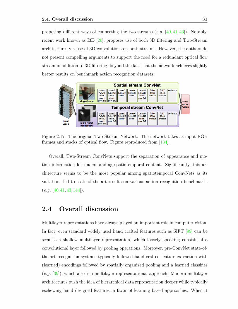
2.3.3 Two-Stream ConvNet
The third type of spatiotemporal architecture relies on a two-stream design. The
standard Two-Stream architecture [134], depicted in Figure 2.17, operates in two
parallel pathways, one for processing appearance and the other for motion by analogy
with the two-stream hypothesis in the study of biological vision systems [55]. Input
to the appearance pathway are RGB images; input to the motion path are stacks
of optical flow fields. Essentially, each stream is processed separately with fairly
standard 2D ConvNet architectures. Separate classification is performed by each
pathway, with late fusion used to achieve the final result. The various improvements
over the original two stream network follow from the same underlying idea while
using various baseline architectures for the individual streams (e.g . [43,143,144]) or
2.4. Overall discussion 31
proposing different ways of connecting the two streams (e.g . [40, 41, 43]). Notably,
recent work known as I3D [20], proposes use of both 3D filtering and Two-Stream
architectures via use of 3D convolutions on both streams. However, the authors do
not present compelling arguments to support the need for a redundant optical flow
stream in addition to 3D filtering, beyond the fact that the network achieves slightly
better results on benchmark action recognition datasets.
Figure 2.17: The original Two-Stream Network. The network takes as input RGBframes and stacks of optical flow. Figure reproduced from [134].
Overall, Two-Stream ConvNets support the separation of appearance and mo-
tion information for understanding spatiotemporal content. Significantly, this ar-
chitecture seems to be the most popular among spatiotemporal ConvNets as its
variations led to state-of-the-art results on various action recognition benchmarks
(e.g . [40, 41,43,144]).
2.4 Overall discussion
Multilayer representations have always played an important role in computer vision.
In fact, even standard widely used hand crafted features such as SIFT [99] can be
seen as a shallow multilayer representation, which loosely speaking consists of a
convolutional layer followed by pooling operations. Moreover, pre-ConvNet state-of-
the-art recognition systems typically followed hand-crafted feature extraction with
(learned) encodings followed by spatially organized pooling and a learned classifier
(e.g . [39]), which also is a multilayer representational approach. Modern multilayer
architectures push the idea of hierarchical data representation deeper while typically
eschewing hand designed features in favor of learning based approaches. When it

2.4. Overall discussion 32
comes to computer vision applications, the specific architecture of ConvNets makes
them one of the most attractive architectures.
Overall, while the literature tackling multilayer networks is very large where each
faction advocates the benefits of one architecture over another, some common “best
practices” have emerged. Prominent examples include: the reliance of most architec-
tures on four common building blocks (i.e. convolution, rectification, normalization
and pooling), the importance of deep architectures with small support convolutional
kernels to enable abstraction with a manageable number of parameters, residual con-
nections to combat challenges in error gradient propagation during learning. More
generally, the literature agrees on the key point that good representations of input
data are hierarchical, as previously noted in several contributions [119].
Importantly, while these networks achieve competitive results in many computer
vision applications, their main shortcomings remain: the limited understanding of
the exact nature of the learned representation, the reliance on massive training
datasets, the lack of ability to support precise performance bounds and the lack of
clarity regarding the choice of the networks hyper parameters. These choices include
the filters sizes, choice of nonlinearities, pooling functions and parameters as well as
the number of layers and architectures themselves. Motivations behind several of
these choices, in the context of ConvNets’ building block, are discussed in the next
chapter.

Chapter 3
Understanding ConvNets Building
Blocks
In the light of the plethora of unanswered questions in the ConvNets area, this
chapter investigates the role and significance of each layer of processing in a typical
convolutional network. Toward this end, the most prominent efforts tackling these
questions are reviewed. In particular, the modeling of the various ConvNet com-
ponents will be presented both from theoretical and biological perspectives. The
presentation of each component ends with a discussion that summarizes our current
level of understanding.
3.1 The convolutional layer
The convolutional layer is, arguably, one of the most important steps in ConvNet
architectures. Basically, convolution is a linear, shift invariant operation that con-
sists of performing local weighted combination across the input signal. Depending
on the set of weights chosen (i.e. the chosen point spread function) different prop-
erties of the input signal are revealed. In the frequency domain, the correlate of
the point spread function is the modulation function that tells how the frequency
components of the input are modified through scaling and phase shifting. Therefore,
it is of paramount importance to select the right kernels to capture the most salient
and important information contained in the input signal that allows for making
33

3.1. The convolutional layer 34
strong inferences about the content of the signal. This section discusses some of the
different ways to approach the kernel selection step.
3.1.1 Biological perspective
Neurophysiological evidence for hierarchical processing in the mamalian visual cor-
tex provides an underlying inspiration for spatial and spatiotemporal ConvNets. In
particular, research that hypothesized a cascade of simple and complex cells that
progressively extract more abstract attributes of the visual input [74] has been of
particular importance. At the very earliest stages of processing in the visual cortex,
the simple cells were shown capable of detecting primitive features such as oriented
gratings, bars and edges, with more complicated tunings emerging at subsequent
stages.
A popular choice for modeling the described properties of cortical simple cells
is a set of oriented Gabor filters or Gaussian derivatives at various scales. More
generally, filters selected at this level of processing typically are oriented bandpass
filters. Many decades later most biological models still rely on the same set of simple
cells at the initial layers of the hierarchy [5,48,79,117,130,131]. In fact, these same
Gabor kernels are also extended to the chromatic [155] and temporal [79] domains
to account for color and motion sensitive neurons, respectively.
Matters become more subtle, however, when it comes to representing cells at
higher areas of the visual cortex and most contributions building on Hubel and
Wiesel’s work strive to find an appropriate representation for these areas. The
HMAX model is one of the most well known models tackling this issue [117]. The
main idea of the HMAX model is that filters at higher layers of the hierarchy are
obtained through the combination of filters from previous layers such that neurons at
higher layers respond to co-activations of previous neurons. This method ultimately
should allow the model to respond to more and more complex patterns at higher
layers as illustrated in Figure 3.1. This approach relates nicely to the Hebbian theory
stating that “cells that fire together, wire together” [65].
Another hallmark of the HMAX model is the assumption that learning comes
into play in order to recognize across various viewpoints of similar visual sequences.

3.1. The convolutional layer 35
Figure 3.1: Illustration of the HMAX Model. This model consists of a hierarchyof cells with alternating simple (S) and complex (C) cells. Filtering operationshappen at the level of the S cells. It is shown in this figure that simple cells atthe initial layer (S1) detect simple oriented bars (i.e. through the use of orientedGabor filters). On the other hand, simple cells at higher layers (S2) respond tofiltering with templates that are combinations of filters used at the previous (S1)layer such that cells at higher layers in the hierarchy detect more complex shapesthan oriented bars. Complex composite cells (C1, C2) intervene between the layersof simple cells to aggregate similarly tuned cells across spatial position and therebyachieve a degree of shift invariance. Figure reproduced from [117].
Direct extensions of this work thereafter explicitly introduce learning to model filters
at higher layers. Among the most successful such approaches is the biologically
motivated network introduced by Serre et al . [131] that attempts to model the
processes taking place at the initial layers of the visual cortex with a network made
of 4 layers where simple (S) and complex (C) cells alternate as illustrated in Figure
3.2. It is seen that each simple cell is directly followed by a complex cell such that
the overall structure of the network can be summarizes as S1 → C1 → S2 → C2.
In this network convolutions take place at the level of the S1 and S2 units. While
the S1 units rely on 2D oriented Gabor filters, the kernels used at the second layer
are based on a learning component. This choice is motivated by biological evidence
suggesting that learning occurs at the higher layers of the cortex [130], although there
also is evidence that learning plays a role at earlier layers of the visual cortex [11].
In this case, the learning process corresponds to selecting a random set of n× n× l
patches, Pi, from a training set at the C1 layer, where n is the spatial extent of
the patch and l corresponds to the number of orientations. The S2 layer feature

3.1. The convolutional layer 36
maps are obtained by performing template matching between the C1 features in
each scale and the set of learned patches Pi at all orientations simultaneously.
A direct extension to this work exists for video processing [79]. The kernels used
for video processing are designed to mimic the behavior of cells in the dorsal stream.
In this case, S1 units involve convolutions with 3D oriented filters. In particular,
third order Gaussian derivative filters are used owing to their nice separability prop-
erties and a similar learning process is adopted to select convolutional kernels for
the S2 and S3 units.
Figure 3.2: The Network Architecture Proposed by Serre et al . Similarly to theHMAX model [117], it consists of alternating simple and complex cells such that theoverall architecture of the proposed networks can be summarized as S1 → C1 →S2 → C2. However, as opposed to the HMAX model, templates used at the levelof the S2 cells are explicitly learned from a training set such that this layer detectscomplex objects (i.e. when trained with an object recognition dataset). The detailsof the process are summarized in the second row of the figure. Figure reproducedfrom [131].
Many variations of the above underlying ideas have been proposed, including
various learning strategies at higher layers [145, 147], wavelet based filters [71], dif-
ferent feature sparsification strategies [73, 110, 147] and optimizations of filter pa-
rameters [107,147].
Another related, although somewhat different, train of thoughts suggest that
there exist more complex cells at higher levels of the hierarchy that are dedicated

3.1. The convolutional layer 37
to capturing intermediate shape representation, e.g . curvatures [120, 121]. While
the HMAX class of models propose modeling shapes via compositions of feature
types from previous layers, these investigations propose an approach that directly
models hypercomplex cells (also referred to as endstopped cells) without resorting
to learning. In particular, models falling within this paradigm model hypercomplex
cells via combination of simple and complex cells to generate new cells that are able
to maximally respond to curvatures of different degrees and signs as well as different
shapes at different locations. In suggesting that hypercomplex cells subserve curva-
ture calculations, this work builds on earlier work suggesting similar functionality,
e.g . [32].
Yet another body of research, advocates that the hierarchical processing (termed
Filter → Rectify → Filter) that takes place in the visual cortex deals progres-
sively with higher-order image structures [5, 48, 108]. It is therefore advocated that
the same set of kernels present at the first layer (i.e. oriented bandpass filters) are
repeated at higher layers. However, the processing at each layer reveals different
properties of the input signal given that the same set of kernels now operate on
different input obtained from a previous layer. Therefore, features extracted at suc-
cessive layers progress from simple and local to abstract and global while capturing
higher order statistics. In addition, joint statistics are also accounted for through
the combination of layerwise responses across various scales and orientations.
Discussion
The ability of human visual cortex in recognizing the world while being invariant
to various changes has been the driving force of many researchers in this field. Al-
though, several approaches and theories have been proposed to model the different
layers of the visual cortex, a common thread across these efforts is the presence of
hierarchical processing that splits the vision task into smaller pieces. However, while
most models agree on the choice of the set of kernels at the initial layers, motivated
by the seminal work of Hubel and Wiesel [74], modeling areas responsible for rec-
ognizing more abstract features seems to be more intricate and controversial. Also,
these biologically plausible models, typically leave open critical questions regarding
3.1. The convolutional layer 38
the theoretical basis of their design decisions. This shortcoming applies to more
theoretically driven models as well, as will be discussed in the next section.
3.1.2 Theoretical perspective
More theoretically driven approaches are usually inspired from biology but strive to
inject more theoretical justifications into their models. These methods usually vary
depending on their kernel selection strategy.
One way of looking at the kernel selection problem is to consider that objects
in the natural world are a collection of a set of primitive shapes and thereby adopt
a shape based solution [45–47]. In this case, the proposed algorithms start by
finding the most primitive shapes in an image (i.e. oriented edges) using a bank of
oriented Gabor filters. Using these edges, or more generally parts, the algorithm
proceeds by finding potential combinations of parts in the next layers by looking
at increasingly bigger neighborhoods around each part. Basically, every time a new
image is presented to the network, votes are collected about the presence of other
part types in the direct neighborhood of a given part in the previous layer. After all
images present in the training set are seen by the network, each layer of the network
is constructed using combinations of parts from the previous layer. The choice of the
combinations is based on the probabilities learned during the unsupervised training.
In reality, such a shape based approach is more of a proof of concept where only
lower layers of the hierarchy can be learned in such an unsupervised way, whereas
higher layers are learned using category specific images as illustrated in Figure 3.3.
Therefore, a good representation of an object can be obtained in higher layers only
if the network saw examples from that object class alone. However, because of this
constraint, such an algorithm cannot be reasonably deployed on more challenging
datasets with objects from different categories that it had not previously seen.

3.1. The convolutional layer 39
Figure 3.3: Sample Parts Learned by the Multilayer Architecture Proposed by Fidleret al . 1st row (left-to-right): Layer 2 and layer 3 sample parts. 2nd and3rd rows: Layer 4 and layer 5 parts learned using faces, cars, and mugs. Figurereproduced from [47].
Another outlook on the kernel selection process is based on the observation
that many training based convolutional networks learn redundant filters. Moreover,
many of the learned filters at the first few layers of those networks resemble oriented
band pass filters; e.g . see Figure 3.8. Therefore, several recent investigations aim at
injecting priors into their network design with a specific focus on the convolutional
filter selection. One approach proposes learning layerwise filters over a basis set of 2D
derivative operators [75] as illustrated in Figure 3.4. While this method uses a fixed
basis set of filters, it relies on supervised learning to linearly combine the filters in
the basis at each layer to yield the effective layerwise filters and it is therefore dataset
dependent. Nonetheless, using a basis set of filters and learning combinations aligns
well with biological models, such as HMAX [117] and its successors (e.g . [79, 131]),
and simplifies the networks’ architecture, while maintaining interpretability. Also,
as learning is one of the bottlenecks of modern ConvNets, using a basis set also eases
this process by tremendously decreasing the number of parameters to be learned. For
these reasons such approaches are gaining popularity in the most recent literature
[28,75,100,148,158].
Interestingly, a common thread across these recent efforts is the aim of reducing
redundant kernels with a particular focus on modeling rotational invariance (al-
though it is not necessarily a property of biological vision). The focus on rotation
is motivated by the observation that, often, learned filters are rotated versions of
one another. For example, one effort targeted learning of rotational equivariance

3.1. The convolutional layer 40
by training over a set of circular harmonics [148]. Alternatively, other approaches
attempt to hard encode rotation invariance by changing the network structure itself
such that for each learned filter a set of corresponding rotated versions are automat-
ically generated either directly based on a predefined set of orientations, e.g . [158],
or by convolving each learned filter with a basis set of oriented Gabor filters [100].
Figure 3.4: An Illustration the Receptive Fields CNN (also known as RFNN). In thisnetwork, the filters used at all layers are built (via learning) as a linear combinationof the basis filter set φm, which is a set nth order Gaussian derivatives. Instead oflearning the kernel parameters of the filters, this network learns the parameters αijused to linearly combine the filters in the basis set. Figure reproduced from [75].
Other approaches push the idea of injecting priors into their network design even
further by fully hand crafting their network via casting the kernel selection problem
as an invariance maximization problem based on group theory, e.g . [15, 28, 113].
For example, kernels can be chosen such that they maximize invariances to small
deformations and translations for texture recognition [15] or to maximize rotation
invariance for object recognition [113].
Arguably, the scattering transform network (ScatNet) has one of the most rigor-
ous mathematical definitions to date [15]. The construction of scattering transforms
starts from the assertion that a good image representation should be invariant to
small, local deformations and various transformation groups depending on the task
at hand. The kernels used in this method are a set of dilated and rotated wavelets
ψλ where λ is the frequency location of the wavelet and it is defined as λ = 2−jr
where 2−j represents the dilation and r represents the rotation. The network is
constructed by a hierarchy of convolutions using various wavelets centered around

3.1. The convolutional layer 41
different frequencies, as well as various nonlinearities as discussed in the next sec-
tion. The frequency locations of the employed kernels are chosen to be smaller at
each layer. The entire process is summarized in Figure 3.5.
Figure 3.5: Scattering Transform Network. In this network, the scattering transformS[λ]x proposed in [15] is applied repeatedly at each layer m on all the outputs U [λi]xfrom a previous layer. Essentially, the outputs of each layer go through the sametransform over and over again, however, the transform targets a different effectivefrequency at each layer and thereby extracts novel information at each layer. Inthis figure, an instantiation of the network with m = 3 layers is depicted as anillustration. Figure reproduced from [15].
A related ConvNet, dubbed SOE-Net, was proposed for spacetime image analysis
[60]. SOE-Net relies on a vocabulary of theory motivated, analytically defined filters.
In particular, its convolutional block relies on a basis set of 3D oriented Gaussian
derivative filters that are repeatedly applied while following a frequency decreasing
path similar to ScatNet as illustrated in Figure 3.6. In this case, however, the
network design is cast in terms of spatiotemporal orientation analysis and invariance
is enforced via a multiscale instantiation of the used basis set.
Loosely speaking both SOE-Net and ScatNet fall under the Filter → Rectify →
Filter paradigm advocated by some biologically based models [5]. Because these
network are based on a rigorous mathematical analysis, they also take into account
the frequency content of the signal as it is processed in each layer. One of the
direct results of this design is the ability to make theory driven decisions regarding
the number of layers used in the network. In particular, given that outputs of the

3.1. The convolutional layer 42
Figure 3.6: SOE-Net Architecture. Local spatiotemporal features at various orien-tations are extracted with an initial processing layer, Lk. C-R-N-S indicate Con-volution, Rectification, Normalization and Spatiotemporal pooling, while R and Lindicate rightward vs. leftward filtered data, resp., with symbol strings (e.g . LR)indicating multiple filterings. A network with only 2 filters (i.e. 2 orientations) isshown for illustration. Each of the feature maps at layer Lk is treated as a newseparate signal and fed back to layer Lk+1 to be convolved with the same set offilters but at a different effective resolution due to spatiotemporal pooling. Figurereproduced from [60].
different layers of the network are calculated using a frequency decreasing path, the
signal eventually decays. Hence, the iterations are stopped once there is little energy
left in the signal. Further, through its choice of filters that admit a finite basis set
(Gaussian derivatives), SOE-Net can analytically specify the number of orientations
required.
Another simple, yet powerful, outlook on the kernel selection process relies on
pre-fixed filters learned using PCA [21]. In this approach, it is argued that PCA
can be viewed as the simplest class of auto-encoders that minimize reconstruction
error. The filters are simply learned using PCA on the entire training dataset. In
particular, for each pixel in each image Xi, a patch of size k1 × k2 is taken and
subjected to a de-meaning operation to yield a set of patches Xi. A collection of
such overlapped patches from each image is stacked together to form the volume X =
[X1, X2, ..., XN ]. The filters used correspond to the first L1 principal eigenvectors of
XXT . These vectors are reshaped to form kernels Wl of size k1 × k2 and convolved
with each input image Xi to obtain feature maps I li . The same procedure is repeated
for higher layers of the network.

3.1. The convolutional layer 43
Compared to ScatNet [15] and SOE-Net [60], the PCA approach work is much
less mathematically involved and relies more on learning. However, it is worth
highlighting that the most basic form of auto-encoder was able to achieve respectable
results on several tasks including face recognition, texture recognition and object
recognition. A closely related approach also relies on unsupervised kernel selection
as learned via k-means clustering [35]. Once again, although such an approach does
not yield state-of-the art results compared to standard learning based architectures
it is worthy of note that it still is competitive even on heavily researched datasets
such as MNIST [91]. More generally, the effectiveness of such purely unsupervised
approaches suggest that there is non-trivial information that can be leveraged simply
from the inherent statistics of the data.
3.1.2.1 Optimal number of kernels
As previously mentioned, the biggest bottleneck of multilayer architectures is the
learning process that requires massive amounts of training data mainly due to the
large number of parameters to be learned. Therefore, it is of paramount importance
to carefully design the network’s architecture and decide on the number of kernels at
each layer. Unfortunately, even hand-crafted ConvNets usually resort to a random
selection of the number of kernels (e.g . [15, 21, 45, 79, 113, 131]). One exception
among the previously discussed analytically defined ConvNets is SOE-Net, which as
previously mentioned, specifies the number of filters analytically owing to its used
of a finite basis set (i.e. oriented Gaussian derivatives).
The recent methods that suggest the use of basis sets to reduce the number of
kernels at each layer [28, 75] offer an elegant way of tackling this issue although
the choice of the set of filters and the number of filters in the set is largely based
on empirical considerations. The other most prominent approaches tackling this
issue aim at optimizing the network architecture during the training process. A
simple approach to deal with this optimization problem, referred to as optimal brain
damage [92], is to start from a reasonable architecture and progressively delete small
magnitude parameters whose deletion does not negatively affect the training process.
A more sophisticated approach [44] is based on the Indian Buffet Process [59]. The
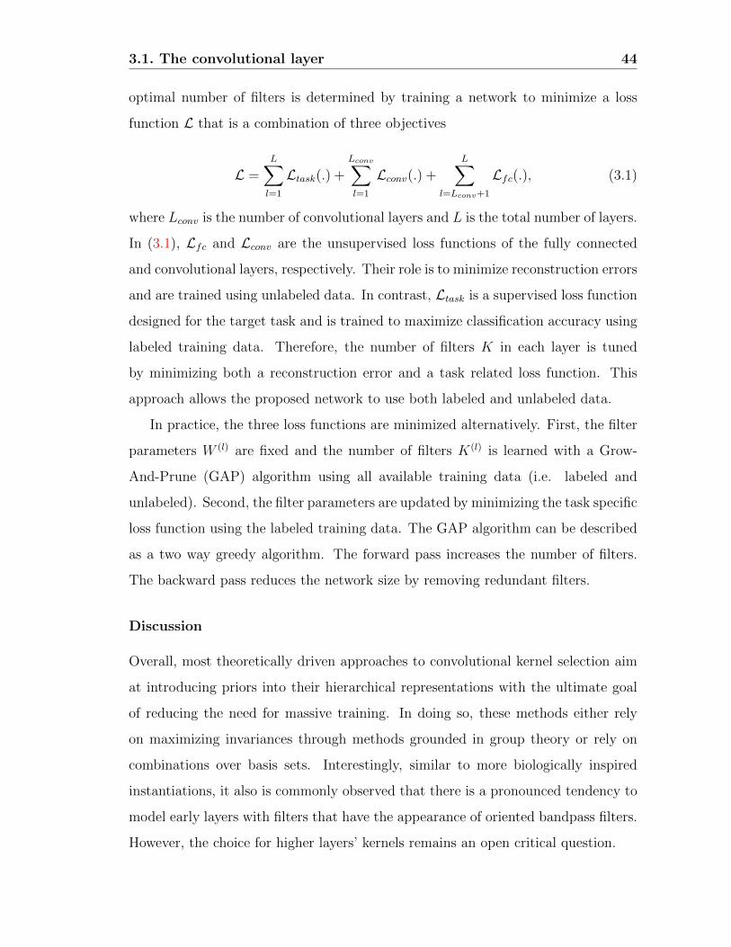
3.1. The convolutional layer 44
optimal number of filters is determined by training a network to minimize a loss
function L that is a combination of three objectives
L =L∑l=1
Ltask(.) +Lconv∑l=1
Lconv(.) +L∑
l=Lconv+1
Lfc(.), (3.1)
where Lconv is the number of convolutional layers and L is the total number of layers.
In (3.1), Lfc and Lconv are the unsupervised loss functions of the fully connected
and convolutional layers, respectively. Their role is to minimize reconstruction errors
and are trained using unlabeled data. In contrast, Ltask is a supervised loss function
designed for the target task and is trained to maximize classification accuracy using
labeled training data. Therefore, the number of filters K in each layer is tuned
by minimizing both a reconstruction error and a task related loss function. This
approach allows the proposed network to use both labeled and unlabeled data.
In practice, the three loss functions are minimized alternatively. First, the filter
parameters W (l) are fixed and the number of filters K(l) is learned with a Grow-
And-Prune (GAP) algorithm using all available training data (i.e. labeled and
unlabeled). Second, the filter parameters are updated by minimizing the task specific
loss function using the labeled training data. The GAP algorithm can be described
as a two way greedy algorithm. The forward pass increases the number of filters.
The backward pass reduces the network size by removing redundant filters.
Discussion
Overall, most theoretically driven approaches to convolutional kernel selection aim
at introducing priors into their hierarchical representations with the ultimate goal
of reducing the need for massive training. In doing so, these methods either rely
on maximizing invariances through methods grounded in group theory or rely on
combinations over basis sets. Interestingly, similar to more biologically inspired
instantiations, it also is commonly observed that there is a pronounced tendency to
model early layers with filters that have the appearance of oriented bandpass filters.
However, the choice for higher layers’ kernels remains an open critical question.

3.2. Rectification 45
3.2 Rectification
Multilayer networks are typically highly nonlinear and rectification is, usually, the
first stage of processing that introduces nonlinearities to the model. Rectification
refers to applying a pointwise nonlinearity (also known as an activation function) to
the output of the convolutional layer. Use of this term borrows from signal process-
ing, wherein rectification refers to conversion from alternating to direct current. It
is another processing step that finds motivation both from biological and theoretical
point views. Computational neuroscientists introduce the rectification step in an
effort to find the appropriate models that explain best the neuroscientific data at
hand. On the other hand, machine learning researchers use rectification to obtain
models that learn faster and better. Interestingly, both streams of research tend
to agree, not only on the need for rectification, but they are also converging to the
same type of rectification.
3.2.1 Biological perspective
From a biological perspective, rectification nonlinearities are usually introduced into
the computational models of neurons in order to explain their firing rates as a
function of the input [31]. A fairly well accepted model for biological neuron’s firing
rate in general is referred to as the Leaky Integrate and Fire (LIF) [31]. This model
explains that the incoming signal to any neuron has to exceed a certain threshold
in order for the cell to fire. Research investigating the cells in the visual cortex
in particular also relies on a similar model, referred to as half wave rectification
[66,74,109].
Notably, Hubel and Wiesel’s seminal work already presented evidence that simple
cells include nonlinear processing in terms of half wave rectification following on
linear filtering [74]. As previously mentioned in Section 3.1, the linear operator
itself can be considered as a convolution operation. It is known that, depending
on the input signal, convolution can give rise to either positive or negative outputs.
However, in reality cells’ firing rates are by definition positive. This is the reason why
Hubel and Wiesel suggested a nonlinearity in the form of a clipping operation that

3.2. Rectification 46
only takes into account the positive responses. More in line with the LIF model,
other research suggested a slightly different half wave rectification in which the
clipping operation happens based on a certain threshold (i.e. other than zero) [109].
Another more complete model also took into account the possible negative responses
that may arise from the filtering operation [66,67]. In this case, the author suggested
a two-path half wave rectification where the positive and negative incoming signals
are clipped separately and carried in two separate paths. Also, in order to deal with
the negative responses both signals are followed by a pointwise squaring operation
and the rectification is therefore dubbed half-squaring (although biological neurons
do not necessarily share this property). In this model the cells are regarded as energy
mechanisms of opposite phases that encode both the positive and negative outputs.
Discussion
Notably, these biologically motivated models of neuronal activation functions have
become common practice in today’s convolutional network algorithms and are, in
part, responsible for much of their success as will be discussed next.
3.2.2 Theoretical perspective
From a theoretical perspective, rectification is usually introduced by machine learn-
ing researchers for two main reasons. First, it is used to increase the discriminating
power of the extracted features by allowing the network to learn more complex
functions. Second, it allows for controlling the numerical representation of the data
for faster learning. Historically, multilayer networks relied on pointwise sigmoidal
nonlinearities using either the logistic nonlinearity or the hyperbolic tangent [91].
Although the logistic function is more biologically plausible given that it does not
have a negative output, the hyperbolic tangent was more often used given that it has
better properties for learning such as a steady state around 0 (See Figures 3.7 (a)
and (b), respectively). To account for the negative parts of the hyperbolic tangent
activation function it is usually followed by a modulus operation (also referred to as
Absolute Value Rectification AVR) [77]. However, recently the Rectified Linear Unit
(ReLU), first introduced by Nair et al . [111], quickly became the default rectification
3.2. Rectification 47
nonlinearity in many fields (e.g . [103]) and particularly computer vision ever since
its first successful application on the ImageNet dataset [88]. It was shown in [88]
that the ReLU plays a key role against overfitting and expediting the training pro-
cedure, even while leading to better performance compared to traditional sigmoidal
rectification functions.
Mathematically, ReLU is defined as follows,
f(yi) = max(0, yi) (3.2)
and is depicted in Figure 3.7 (c). The ReLU operator has two main desirable prop-
erties for any learning based network. First, ReLU does not saturate for positive
input given that its derivative is 1 for positive input. This property makes ReLU
particularly attractive since it removes the problem of vanishing gradients usually
present in networks relying on sigmoidal nonlinearities. Second, given that ReLU
sets the output to 0 when the input is negative, it introduces sparsity, which has the
benefit of faster training and better classification accuracy. In fact, for improved
classification it is usually desirable to have linearly separable features and sparse
representations are usually more readily separable [54]. However, the hard 0 satura-
tion on negative input comes with its own risks. Here, there are two complementary
concerns. First, due to the hard zero activation some parts of the network may never
be trained if the paths to these parts were never activated. Second, in a degenerate
case where all units at a given layer have a negative input, back propagation might
fail and this will lead to a situation that resembles the vanishing gradient problem.
Because of these potential issues many improvements to the ReLU nonlinearity have
been proposed to deal better with the case of negative outputs while keeping the
advantages of ReLU.
Variations of the ReLU activation function include the Leaky Rectified Lin-
ear Unit (LReLU) [103] and its closely related Parametric Rectified Linear Unit
(PReLU) [63] that are mathematically defined as
f(yi) = max(0, yi) + aimin(0, yi) (3.3)

3.2. Rectification 48
and depicted in Figure 3.7 (d). In LRelu ai is a fixed value, whereas it is learned
in PReLU. LReLU was initially introduced to avoid zero gradients during back
propagation but did not improve the results of the tested networks significantly.
Also, it heavily relied on cross validation experimentation in the selection of the
parameter ai. In contrast, PReLU optimizes the value of this parameter during
training, which leads to a bigger boost in performance. Notably, one of the most
important results of PReLU is the fact that early layers in the network tended to
learn a higher value for the parameters ai, whereas that number is almost negligible
for higher layers in the network’s hierarchy. The authors speculate that this result
could be due to the nature of the filters learned at different layers. In particular, since
first layer kernels are usually oriented bandpass like filters both parts of the response
are kept as they represent a potentially significant difference in the incoming signal.
On the other hand, kernels at higher layers are tuned to detect specific objects and
are trained to be more invariant.
(a) Logistic (b) tanh (c) ReLU
(d) LReLU/PReLU (e) SReLU (f) EReLU
Figure 3.7: Nonlinear Rectification Functions Used in the Multilayer Networks Lit-erature.
Interestingly, another rectification function, dubbed Concatenated Rectified Lin-
ear Unit (CReLU), was proposed based on similar observations [132]. In that case,
the authors propose CReLU starting from the observation that kernels learned at

3.2. Rectification 49
the initial layers of most ConvNets tend to form negatively correlated pairs (i.e.
filters that are 180 degrees out of phase) as shown in Figure 3.8. This observa-
tion implies that the negative responses eliminated by the ReLU nonlinearity are
replaced by learning kernels of opposite phase. By replacing ReLU with CReLU,
the authors were able to demonstrate that a network designed to encode a two path
rectification leads to a better performance, while reducing the number of parameters
to be learned through removing redundancies.
Figure 3.8: Visualization of Conv1 Filters Learned by AlexNet Trained on ImageNetDataset. Figure reproduced from [132].
Other variation in the ReLU family include: the the S-shaped Rectified Linear
Unit (SReLU) [82], defined as
f(yi) =
tri + ari (yi − tri ) if yi ≥ tri
yi if tri > yi > tli
tli + ali(yi − tli) if yi ≤ tli
(3.4)
and depicted in Figure 3.7 (e), which was introduced to allow networks to learn
more nonlinear transformations. It consists of three piecewise linear functions with
4 learnable parameters. The main downside of SReLU is that it introduces several
parameters to learn (i.e. particularly if the parameters are not shared among several
channels), which makes learning more complex. This concern is especially true given
that a bad initialization of those parameters might impair the learning. Yet another
variant is the Exponential Linear Unit (ELU) [26], defined as
f(yi) =
yi if x > 0
α(exp(yi)− 1) if x ≤ 0
(3.5)
3.2. Rectification 50
and depicted in Figure 3.7 (f), which is motivated by a desire to increase invariance
to noise by forcing the signal to saturate to a value controlled by a variable α for
negative inputs. A common thread across all variations in the ReLU family is that
the negative input should be taken into account as well and dealt with appropriately.
Another outlook on the choice of the rectification nonlinearity is presented in
the Scattering Network [15]. As previously mentioned in Section 3.1, ScatNet is
handcrafted with the main goal of increasing invariance of the representation to var-
ious transformations. Since it broadly relies on Wavelets in the convolutional layer
it is invariant to small deformations; however, it remains covariant to translation.
Therefore, the authors rely on an integral operation defined as
S[λ]x(u) = ||x ? ψλ||1 =
∫|x ? ψλ(u)| du (3.6)
and implemented as average pooling, to add a level of shift invariance. Hence,
in anticipation of the subsequent pooling operation that can drive the response
towards zero, i.e. in the case where positive and negative responses cancel each
other, the L1(R2) norm operator is used in the rectification step to make all responses
positive. Once again, it is worth noting here that traditional ConvNets that relied
on the hyperbolic tangent activation function also used a similar AVR rectification
to handle negative outputs [77, 91]. Also, more biologically motivated models, such
as the half-squaring rectification [66,67], relied on pointwise squaring of the signal to
deal with negative responses. This squaring operation also allows for reasoning about
the responses in terms of energy mechanisms. Interestingly, one of the recent more
theory driven convolutional networks [60] also proposed a a two path rectification
strategy defined as
E+(x; θi, σj) = (max[C(x; θi, σj), 0])2
E−(x; θi, σj) = (min[C(x; θi, σj), 0])2, (3.7)
where C(x; θi, σj) is the output from the convolution operation. This rectification
strategy combines the idea of keeping both phases of the filtered signal and pointwise
squaring and thereby allows for conservation the signals magnitude and phase while

3.3. Normalization 51
considering the resulting signal in terms of spectral energy.
Discussion
Interestingly, the broad class of ReLU nonlinearities clearly became the most popular
choice for the rectification stage from a theoretical perspective. Notably, the choice
of completely neglecting the negative inputs (i.e. as done in ReLU) seems to be more
questionable as evidenced by the many contributions proposing alternatives to this
choice [26,63,82,103,132]. It is also important to compare the behavior of the ReLU
with AVR rectification used in ScatNet [15] and older ConvNet architectures [77].
While AVR preserves the energy information but erases the phase information, ReLU
on the other hand keeps the phase information in some sense, by retaining the
positive parts of the signal only; however, it does not preserve the energy as it
throws away half of the signal. Significantly, methods that try to preserve both
(e.g . CReLU [132] and the use of (3.7) in SOE-Net [60]) were able to achieve better
performances across several tasks, and such methods are also in consensus with
biological findings [66].
3.3 Normalization
As previously mentioned, multilayer architectures are highly nonlinear due to the
cascade of nonlinear operations that take place in these networks. In addition to the
rectification nonlinearity discussed in the previous section, normalization is another
nonlinear block of processing that plays a significant role in ConvNet architectures.
The most widely used form of normalization used in ConvNets is the so called Divi-
sive Normalization or DN (also known as local response normalization). This section
sheds light on the role of the normalization step and describes how it corrects for
some of the shortcomings of the previous two blocks of processing (i.e. Convolution
and Rectification). Once again the role of normalization will be discussed both from
biological and theoretical perspectives.

3.3. Normalization 52
3.3.1 Biological perspective
Normalization was proposed early on by neurophysiologists to explain the phe-
nomenon of light adaptation in the retina [13] and was later extended to explain
the nonlinear properties of neurons in the mammalian visual cortex [66]. Indeed,
from a biological point of view, the need for a normalization step stems from two
main observations [66, 67]. First, although cells responses were proven to be stim-
ulus specific [74], it was also shown that cell responses can inhibit one another
and that there exists a phenomenon of cross-orientation suppression, where the re-
sponse of a neuron to its preferred stimuli is attenuated if it is superimposed with
another ineffective stimuli [14, 19, 67]. Neither the linear models (i.e. in the convo-
lution step) nor the different forms of rectification discussed in the previous section,
such as half-wave rectification proposed by computational neuroscientists, explain
this cross-orientation suppression and inhibition behavior. Second, while cell re-
sponses are known to saturate at high contrast, a model relying only on convolution
and unbounded rectifiers, such as ReLU, will have values that keep increasing with
increasing contrast. These two observations suggested the need for a step that dis-
counts the responses of other stimuli in order to keep the specificity of each cell and
make it contrast invariant while explaining other inhibition behaviors of cells.
One popular model to deal with these issues includes a divisive normalization
block described mathematically as follows
Ei =Ei
σ2 +∑
j Ej, (3.8)
where Ei is the output of a squared, half wave rectified convolution operation, pooled
over a set of orientations and scales j and σ2 is a saturation constant that can be
chosen based on either one of two adaptation mechanisms [66]. In the first case, it
could be a different value for each cell learned from the cell’s response history. The
second possibility is to derive it from the statistics of the responses of all cells. This
divisive normalization scheme discards information about magnitude of the contrast
in favor of encoding the underlying image pattern in terms of relative contrast across
the input responses, Ej, in the normalization operation, (3.8). Use of this model

3.3. Normalization 53
seemed to provide a good fit to neuron responses of mammalian visual cortex [67]. It
was also shown that it explains well the cross-orientation suppression phenomenon
as well [14].
Discussion
Interestingly, most of the studies investigating the role of divisive normalization
show that neuronal models including it fit well the recorded data (e.g . [14,19,66,67]).
Indeed, more recent studies suggest that divisive normalization could also explain
the phenomenon of adaptation in IT cortex where the neural responses decrease
with stimulus repetition (e.g . [83]). Moreover, the suggested prevalence of divisive
normalization in several areas of the cortex lead to the hypothesis that Divisive
Normalization can be seen as a canonical operation of the mammalian visual cortex
similar to the operation of convolution [19].
3.3.2 Theoretical perspective
From a theoretical perspective, normalization has been explained as being a method
of achieving efficient coding when representing natural images [102]. In that work,
the normalization step was motivated by findings regarding the statistics of natural
images [102] that are known to be highly correlated and for containing very redun-
dant information. In light of these findings, the normalization step was introduced
with the goal of finding a representation that minimizes statistical dependencies in
images. To achieve this goal a popular derivation discussed thoroughly in [101,102]
starts by representing images using a statistical model based on a Gaussian Scale
Mixture. Using this model and an objective function whose role is to minimize
dependencies, a nonlinearity is derived in the form of
ri =xi−
∑j ajxj√
b+∑
k cj(xj −∑
k akxk)2
(3.9)
where xi and ri are the input and output images, respectively, while b, ai and ci
are parameters of the divisive normalization that can be learned from a training
set. Notably, there exists a direct relationship between the definition of the divisive

3.3. Normalization 54
normalization introduced to deal with redundancies and high order dependencies in
natural images, (3.9), and that suggested to best fit neuron responses in the visual
cortex, (3.8). In particular, with a change of variable where we set yi = xi −∑j
ajxj,
we see that the two equations are related, subject to the square root difference, by
an elementwise operation, (i.e. squaring, with Ei = y2i ), and thereby both models
achieve the goal of maximizing independence while satisfying neuroscientific obser-
vations.
Another way of looking at normalization in ConvNets in particular is to consider
it as a way of enforcing local competition between features [77, 91], similar to the
one taking place in biological neurons. This competition can be enforced between
adjacent features within a feature map through subtractive normalization or between
feature maps through divisive normalization operating at the same spatial locations
across feature maps. Alternatively, divisive normalization can be seen as a way of
minimizing sensitivity to multiplicative contrast variation [60]. It was also found, on
deeper network architectures, that divisive normalization was helpful in increasing
the generalization power of a network [88].
More recent ConvNets rely on what is referred to as batch normalization [129].
Batch normalization is another kind of divisive normalization that takes into account
a batch of the training data to learn normalization parameters (i.e. the mean and
variance in equation (3.10)) and it also introduces new hyperparameters, γ(k)and
β(k), to control the amount of normalization needed at each layer.
Batch normalization can be summarized in two steps. First, at any layer with a
d-dimensional input x = (x(1)... x(d)), each scalar feature is independently normalized
according to
x(k) =x(k) − E[x(k)]√
V ar[x(k)], (3.10)
with E[x(k)] being the mini-batch mean calculated as E[x(k)] = 1m
∑mi=1 xi over
the m samples of the mini-batch, and V ar[x(k)] is the variance of the same mini-
batch calculated as V ar[x(k)] = 1m
∑mi=1(xi − E[x(k)])2. Second, the output of the
normalization in equation (3.10) is subject to a linear transformation such that the

3.3. Normalization 55
final output of the proposed batch normalization block is given by y(k) = γ(k)x(k) +
β(k), with γ(k)and β(k) being hyperparameters to be learned during training.
The first step in batch normalization aims at fixing the means and variances of
the inputs at each layer. However, since that normalization strategy can change or
limit what a layer can represent, the second linear transformation step is included to
maintain the network’s representational power. For example, if the original distri-
bution at the input was already optimal, then the network can restore it by learning
an identity mapping. Therefore, the normalized inputs, x(k), can be thought of as
being inputs to a linear block added at each layer of a network.
Batch normalization was first introduced as an improvement to traditional di-
visive normalization with the ultimate goal of reducing the problem of internal
covariate shift, which refers to the continuous change of the distribution of inputs
at each layer [129]. The changing scale and distribution of inputs at each layer
implies that the network has to significantly adapt its parameters at each layer and
thereby training has to be slow (i.e. use of small learning rate) for the loss to keep
decreasing during training (i.e. to avoid divergence during training). Therefore,
batch normalization was introduced to guarantee more regular distributions at all
inputs.
This normalization strategy was inspired by general rules of thumb established
for efficient training of ConvNets. In particular, for good generalization performance
in ConvNets it is common practice to enforce that all training and testing set sam-
ples have the same distribution (i.e. through normalization). For example, it has
been shown that networks converge faster when the input is always whitened [77,91].
Batch normalization builds on this idea by considering that each layer can be con-
sidered as a shallow network. Therefore, it would be advantageous to make sure that
the inputs keep the same distribution at each layer and this is enforced by learning
the distribution of the training data (using mini-batches) and using the statistics
of the training set to normalize each input. More generally, it is also important to
remember that, from a machine learning perspective, such a normalization scheme
can also make features easier to classify. For example, if two different inputs induce
two different outputs, they are more easily separable by a classifier if the responses

3.3. Normalization 56
lie within the same range and it is therefore important to process the data to satisfy
this condition.
Similar to divisive normalization, batch normalization also proved to play an
important role in ConvNets. In particular, it has been shown that batch normaliza-
tion not only speeds up training, but it also plays a non-trivial role in generalization
where it was able to outperform previous state-of-the-art on image classification (on
ImageNet in particular) while removing the need for Dropout regularization [88].
In comparison, batch normalization is somewhat similar to divisive normalization
in the sense that they both make the scale of the inputs at each layer similar.
However, Divisive Normalization normalizes the values for each input by dividing it
by all other inputs at the same location within the same layer. Batch normalization,
on the other hand, normalizes each input with respect to statistics of the training set
at the same location (or more accurately of the statistics of a mini-batch containing
examples from the entire training set). The fact that batch normalization relies on
the statistics of a training set may explain the fact that it improves the generalization
power of the representation.
One problem with batch normalization is its dependence on the mini-batch size:
It might not properly represent the training set at each iteration, if it is chosen to
be too small; alternatively, it can have a negative effect of slowing down training, if
it is too big (i.e. since the network has to see all training samples under the current
weights to calculate the mini-batch statistics). Also, batch normalization is not
easily applicable to recurrent neural networks since it relies on statistics calculated
over a mini-batch of training samples. For this reason, layer normalization has been
proposed in [4]. Layer normalization follows the same procedure proposed in batch
normalization and the only difference lies in the way normalization statistics are
calculated. While batch normalization calculates statistics over a mini-batch, layer
normalization calculates statistics for each input separately using all feature maps
or hidden units within any one layer. Consequently, in batch normalization each
unit is normalized with different statistics relevant to that unit only, whereas layer
norm normalizes all units in the same way.
While layer norm was shown to be effective on language related applications

3.4. Pooling 57
where recurrent networks are usually more suitable, it failed to compete with Con-
vNets trained with batch normalization for image processing tasks [129]. One pos-
sible explanation proposed by the authors is that in ConvNets all units do not make
an equal contribution in the activation of a unit at the output; therefore, the un-
derlying assumption that this is the case in layer normalization (i.e. using all units
to calculate the statistics of the normalization) does not hold for ConvNets.
Discussion
The common thread across the contributions discussed in this subsection is the
fact that they all agree on the important role of normalization in improving the
representational power of multilayer architectures. Another important point to note
is that they all share the same goal of reducing redundancies in the input as well as
bringing it to the same scale even while casting the problem under different forms.
Indeed, while early proposals of divisive normalization, e.g . [102], explicitly cast
the problem as a redundancy reduction problem, newer proposals such as batch
normalization [129] are also implicitly enforcing this operation through whitening
of the data at each layer. Finally, reflecting back on the normalization problem
from a biological perspective, it is important to note that biological systems are
also efficient in encoding the statistical properties of natural signals in the sense
that they represent the world with small codes. Therefore, one might hypothesize
that they are also performing similar operations of divisive normalization to reduce
redundancies and obtain those efficient codes.
3.4 Pooling
Virtually any ConvNet model, be it biologically inspired, purely learning based or
completely hand-crafted, includes a pooling step. The goal of the pooling operation
is to bring a level of invariance to changes in position and scale as well as to aggregate
responses within and across feature maps. Similar to the three building blocks of
ConvNets discussed in the previous sections, pooling is also supported by biological
findings as well as more theory driven investigations. The major debate when it

3.4. Pooling 58
comes to this layer of processing in convolutional networks is on the choice of the
pooling function. The two most widely encountered variations are average and
max pooling. This section explores the advantages and shortcomings of each and
discusses other variations as described in related literature.
3.4.1 Biological perspective
From a biological perspective, pooling is largely motivated by the behavior of the
cortical complex cells [18, 67, 74, 109]. In their seminal work, Hubel and Wiesel [74]
found that, just like simple cells, complex cells are also tuned to a specific orientation,
but as opposed to simple cells, complex cells exhibit a level of position invariance.
They suggest that this result is achieved through some sort of pooling in which
the responses of simple cells tuned to the same orientation are pooled across space
and/or time as illustrated in Figure 3.9.
Figure 3.9: An Illustration of the Difference Between Simple and Complex Cells.This illustration suggests that complex cells responses result from combinations ofsimple cells responses.
Some of the early biologically inspired convolutional networks such as Fukushima’s
neocognitron [49] and the original LeNet network [91] relied on average pooling.
In these efforts, average pooling followed by sub-sampling is largely motivated by
the findings of Hubel and Wiesel and it is used to decrease the network’s sensi-
tivity to position changes. On the other hand, the HMAX [117] class of networks
(e.g . [79,110,130,131]) rely on max pooling instead. Supporters of the max pooling
strategy claim that it is more plausible when the input to the pooling operator is
a set of Gabor filtered images (i.e. the typical model for simple cells). In fact, the
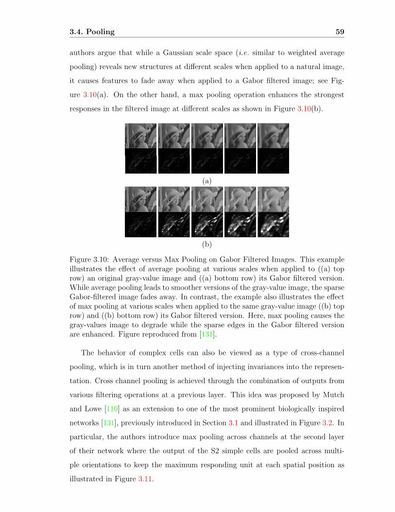
3.4. Pooling 59
authors argue that while a Gaussian scale space (i.e. similar to weighted average
pooling) reveals new structures at different scales when applied to a natural image,
it causes features to fade away when applied to a Gabor filtered image; see Fig-
ure 3.10(a). On the other hand, a max pooling operation enhances the strongest
responses in the filtered image at different scales as shown in Figure 3.10(b).
(a)
(b)
Figure 3.10: Average versus Max Pooling on Gabor Filtered Images. This exampleillustrates the effect of average pooling at various scales when applied to ((a) toprow) an original gray-value image and ((a) bottom row) its Gabor filtered version.While average pooling leads to smoother versions of the gray-value image, the sparseGabor-filtered image fades away. In contrast, the example also illustrates the effectof max pooling at various scales when applied to the same gray-value image ((b) toprow) and ((b) bottom row) its Gabor filtered version. Here, max pooling causes thegray-values image to degrade while the sparse edges in the Gabor filtered versionare enhanced. Figure reproduced from [131].
The behavior of complex cells can also be viewed as a type of cross-channel
pooling, which is in turn another method of injecting invariances into the represen-
tation. Cross channel pooling is achieved through the combination of outputs from
various filtering operations at a previous layer. This idea was proposed by Mutch
and Lowe [110] as an extension to one of the most prominent biologically inspired
networks [131], previously introduced in Section 3.1 and illustrated in Figure 3.2. In
particular, the authors introduce max pooling across channels at the second layer
of their network where the output of the S2 simple cells are pooled across multi-
ple orientations to keep the maximum responding unit at each spatial position as
illustrated in Figure 3.11.

3.4. Pooling 60
Figure 3.11: Cross-Channel Pooling Illustration. (left) Dense simple cell responsesresulting from filtering operations with Gabor filters tuned to various orientations(4 orientations are shown here for illustration purposes) (right) Sparsified simplecell responses resulting from cross-channel pooling using the max operator (i.e. foreach pixel location, the maximum response across feature maps is kept). Figurereproduced from [110].
Discussion
Overall, based on the description of complex cells, it seems that from a biological
perspective both average and max pooling are plausible, although there is more
work arguing in favor of average pooling. Independently from the choice of the
pooling operator, the fact is that there is general agreement on the existence and
significance of pooling. A probably more important question lies in the choice of
the receptive field or the units over which pooling is performed. This aspect of
the pooling operation is further explored in more theory driven work, as will be
described in the next section.
3.4.2 Theoretical perspective
Pooling has been a component of the computer vision representational pipelines for
some time, e.g . [30, 49, 89, 91, 99], with the goal of introducing some level of invari-
ance to image transformations and better robustness to noise and clutter. From a
theoretical perspective, probably one of the most influential works discussing the
importance and role of pooling was Koendrink’s concept of locally orderless im-
ages [87]. This work argued in favor of pooling whereby the exact position of pixels
within a Region Of Interest (ROI), i.e. a pooling region, can be neglected even while
conserving the global image structure. Currently, virtually all convolutional archi-
tectures include a pooling block as part of its processing stages. As with biologically
motivated models, more theory driven approaches typically employ either average
or max pooling.

3.4. Pooling 61
Recent work approaching their network’s design from a purely theory based per-
spective, e.g . ScatNet [15] and SOE-Net [60], rely on a form of average pooling.
In particular, their networks rely on a weighted sum pooling operation. These ap-
proaches tackle the pooling problem from a frequency domain point of view; there-
fore, their choice of average pooling is motivated by a desire to keep track of the
frequency content of the signal. Average pooling allows these networks to act on
different frequencies at each layer while downsampling the images to increase in-
variance and reduce redundancies. At the same time their controlled approach to
specifying pooling parameters allows them to avoid aliasing during the pooling op-
eration. Notably, in SOE-Net’s investigation, the superiority of weighted average
pooling was empirically demonstrated over both simple box car pooling and max
pooling.
Interestingly, most of the early convolutional architectures relied on average pool-
ing as well, e.g . [49,91], but it has slowly fallen out of favor in many learning based
convolutional architectures and been replaced by max pooling. This trend has been
mainly driven by small differences in performance. However, the role of pooling in
a network is significant and needs more careful consideration. In fact, early work
exploring the role of pooling [77] demonstrated that the type of pooling plays such
a significant role in a ConvNet architecture that even an otherwise randomly initial-
ized network yielded competitive results on the task of object recognition provided
the appropriate type of pooling is used. In particular, this work compared aver-
age and max pooling and demonstrated that with a randomly initialized network
average pooling yields superior performance.
Other work more systematically compared average and max pooling empiri-
cally [128] and suggested that there exists a complementarity between the two types
of pooling depending on the input type and the transformations it undergoes. There-
fore, this work implied that ConvNets can benefit from using more than one pooling
option throughout the architecture. Yet other work considered the question from
a purely theoretical perspective [12]. Specifically, this work examined the effect of
average versus max pooling on the separability of extracted features. The main
conclusions of this paper can be summarized in two points. First, the authors argue

3.4. Pooling 62
that max pooling is more suitable when the pooled features are very sparse (e.g .
when pooling is preceded by a ReLU). Second, the authors suggest that the pool-
ing cardinality should increase with the input size and that the pooling cardinality
affects the pooling function. More generally, it was shown that beyond the pooling
type, the pooling size plays an important role as well.
The importance of the pooling cardinality was also explored in various other
studies, albeit empirically [27, 81]. Indeed, the role of pooling cardinality was first
discussed in the context of the earlier hand-crafted feature extraction pipeline [81].
In particular, this work builds on the spatial pyramid pooling [89] encoding method
while highlighting the shortcoming of using predetermined fixed-size pooling grids.
The authors suggest learning the pooling windows’ sizes as part of the classifier
training. More specifically, the authors suggest randomly picking various pooling
regions of different cardinalities and training the classifier to pick the pooling region
that yields the highest accuracy. The main motivation behind this learning based
strategy is to make pooling adaptive to the dataset. For example, the optimal pool-
ing regions for an outdoor scene may lie along the horizon, which does not necessarily
apply to indoor scenes. Similarly, for video action recognition it proved more per-
spicuous to adapt the pooling region to the most salient parts of a video [39]. The
role of the pooling window size or cardinality was also directly explored in a neural
network context [27]. Here, the authors suggest that features that are most similar
should be pooled together. The authors propose finetuning the pooling support (i.e.
pooling regions) of their network in an unsupervised manner. In particular, pooling
windows are chosen to group together similar features according to a pairwise simi-
larity matrix, where the similarity measure is squared correlation. Beyond average
and max pooling operations, the common thread across these investigations is the
importance of the pooling region independently from the pooling function.
Other work approaches the choice of pooling and its corresponding parameters
from a pure machine learning point of view [58, 96, 153]. From this perspective,
pooling is advocated as a regularization technique that allows for varying the net-
work’s structure during training. In particular, pooling allows for the creation of
sub-models within the big architecture thanks to the variation of pathways that a

3.4. Pooling 63
back propagated signal may take during training. These variations are achieved
with methods such as stochastic pooling [153] or cross-channel pooling used in the
maxout network [58] and Network in Network (NiN) [96]. NiN was first introduced
as a way to deal with overfitting and correct for the over-complete representation
of ConvNets [96] . In particular, due to the large number of kernels used at each
layer, it was noticed that many networks often end up learning redundant filters
after training. Therefore, NiN is introduced to reduce redundancies at each layer
by training the network to learn which feature maps to combine using a weighted
linear combination. Similar to NiN, the Maxout network [58] introduces cross chan-
nel pooling wherein the output is set as the maximum across k feature maps on a
channelwise basis. Notably, a recent proposal also relied on cross channel pooling to
minimize redundancies [60] even while being completely learning free. In this work,
the network is based on a fixed vocabulary of filters and cross channel pooling is
designed to group together feature maps resulting from filtering operations with the
same kernel. Beyond minimizing redundancies, this approach was adopted to allow
the network size to remain manageable, while maintaining interpretability.
Stochastic Pooling (SP) [153] was also introduced as a regularization technique.
However, different from maxout and NiN, which perform cross channel pooling, SP
acts within a feature map. In particular, stochastic pooling is inspired from the
dropout technique that is widely used in fully connected layers, but SP is applied
to convolutional layers instead. It relies on introducing stochasticity to the pooling
operation that forces the back propagated signal to randomly take different pathways
at each iteration during training. The method starts by normalizing feature map
responses, ai, within each region to be pooled, Rj, as
pi =ai∑
k∈Rjak. (3.11)
The normalized values, pi, are then used as the probabilities of a multinomial distri-
bution, which is in turn used to sample a location l within the region to be pooled.
The corresponding activation al is the pooled value. Importantly, although stochas-
tic pooling relies on selecting one value from any region Rj (i.e. similar to max
pooling), the pooled value is not necessarily the largest in Rj. Here, it is important

3.4. Pooling 64
to note that a different pooling strategy is adopted during testing. At test time,
the probabilities are no longer used to sample a location during pooling; instead,
they are used as the weights of a weighted sum pooling operation. Hence stochas-
tic pooling is closer in spirit to max pooling during training and closer to average
pooling during testing. The authors argue that the adopted pooling strategy during
training allows for creating different models thanks to varying pathways, while the
pooling used during testing allows for creating a rough average approximation over
all possible models seen during training. In summary, stochastic pooling can be seen
as an attempt to take the best of both average and max pooling.
Another approach that attempts to achieve a balance between average and max
pooling suggests letting the network learn the optimal pooling method [95]. This
idea of multiple pooling strategies is motivated by experiments demonstrating that
the choice of optimal pooling strategy is affected by the input [128]. In particular,
the authors propose three different methods of combining the benefits of average
and max pooling, namely; mixed, gated and tree pooling. Mixed pooling combines
average and max pooling independently from the region to be pooled, where the
network is trained to learn the mixing proportion according to
fmix(x) = alfmax(x) + (1− al)favg(x), (3.12)
subject to the constraint al ∈ [0, 1]. In gated max-average pooling the mixing
proportion is adaptive to the region to be pooled. In particular, the network is
trained to learn a gating mask, w, that is applied to the input data via pointwise
multiplication. Using this gating mask, the mixing function is now defined as
fmix(x) = σ(wTx)fmax(x) + (1− σ(wTx))favg(x), (3.13)
with σ(wTx) = 1(1+exp(−wTx))
.
The third pooling strategy proposed in this work is tree pooling, which can
be viewed as an extreme version of gated pooling. In tree pooling, not only the
mixing proportions are learned but the pooling functions to be combined are learned
as well. Specifically, a tree structure is adopted to learn the parameters of the
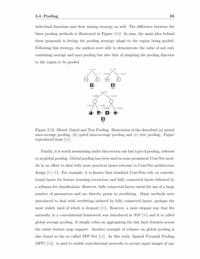
3.4. Pooling 65
individual functions and their mixing strategy as well. The difference between the
three pooling methods is illustrated in Figure 3.12. In sum, the main idea behind
these proposals is letting the pooling strategy adapt to the region being pooled.
Following this strategy, the authors were able to demonstrate the value of not only
combining average and max pooling but also that of adapting the pooling function
to the region to be pooled.
Figure 3.12: Mixed, Gated and Tree Pooling. Illustration of the described (a) mixedmax-average pooling, (b) gated max-average pooling and (c) tree pooling. Figurereproduced from [95].
Finally, it is worth mentioning under this section one last type of pooling, referred
to as global pooling. Global pooling has been used in some prominent ConvNet mod-
els in an effort to deal with more practical issues relevant to ConvNet architecture
design [62, 96]. For example, it is known that standard ConvNets rely on convolu-
tional layers for feature learning/extraction and fully connected layers followed by
a softmax for classification. However, fully connected layers entail the use of a large
number of parameters and are thereby prone to overfitting. Many methods were
introduced to deal with overfitting induced by fully connected layers, perhaps the
most widely used of which is dropout [88]. However, a more elegant way that fits
naturally in a convolutional framework was introduced in NiN [96] and it is called
global average pooling. It simply relies on aggregating the last layer features across
the entire feature map support. Another example of reliance on global pooling is
also found in the so called SPP-Net [62]. In this work, Spatial Pyramid Pooling
(SPP) [89], is used to enable convolutional networks to accept input images of any

3.4. Pooling 66
size. In fact, ConvNets require fixed size input due to the use of fully connected
layers. SPP-Net introduces spatial pyramid pooling after the last convolutional
layer to correct for this difficulty. In particular, spatial pyramid pooling is used to
generate a fixed size representation independently from the size of the input image
as illustrated in Figure 3.13. Notably, global average pooling used in NiN, is akin
to performing spatial pyramid pooling at the last layer of the ConvNet where the
pyramid consists of only the coarsest level.
Figure 3.13: Spatial Pyramid Pooling Network. SPP is applied to the feature mapsof the last convolutional layer of a network. Because the spatial bins are proportionalto the image size, SPP generates feature vectors of the same size independently of theinput image size. Hence SPP-Net does not require input images to be pre-processedsuch that they are of the same size. Figure reproduced from [62].
Discussion
Traditionally, the default functions used in pooling have relied on either the average
or max operators. However, several investigations revealed a certain complementary
between the two showing that more parameters should be taken into account when
choosing the pooling operation. Due to such observations, recent research has been
pushing to extend the idea of training to include learning the pooling functions and
their parameters. However, this direction entails an increase in the number of pa-
rameters to be learned and thereby more chances of overfitting. Importantly, this
approach is to be taken with caution as it would likely further obscure our knowl-

3.5. Overall discussion 67
edge and understanding of the learned representations. In complement, pooling
parameters can be specified on a theoretical basis for cases where previous stages
of processing have adequate analytic detail. Overall, pooling should be viewed as a
way to summarize information from multiple features into a compact form that pre-
serves the important aspects of the signal while discarding details. Beyond deciding
how to summarize the features, it is clear that the harder problem is to determine
what constitutes data that should be pooled and where that data is present.
3.5 Overall discussion
This chapter discussed the role and importance of the most widely used building
blocks in a typical ConvNet architecture in an effort to understand the working prin-
ciples of ConvNets. In particular, the details of each block were addressed from both
biological and theoretical perspectives. Overall, various common threads emerge
from the exploration of the discussed building blocks. In particular, it appears that
all blocks find relatively strong motivations from the operations taking place in the
visual cortex. Further, although all blocks play a significant role in ConvNets, it
appears that the selection of the convolutional kernels is the most important aspect,
as evidenced by the larger body of literature tackling this block. More importantly,
it seems that more recent ConvNet architectures discussed throughout this chapter
(e.g . [15,28,60,75,148]) are aiming at minimizing the need for heavy training based
solutions by incorporating more controlled building blocks at various stages of their
networks. These recent approaches are in turn motivated by various efforts that
revealed the sub-optimality of the learning based ConvNets (e.g . predominant re-
dundancies in some of the widely used learned ConvNets) via layerwise visualization
and ablation studies, as will be discussed in the next chapter.
Chapter 4
Current Status
The review of the role of the various components of ConvNet architectures empha-
sized the importance of the convolutional block, which is largely responsible for
most abstractions captured by the network. In contrast, this component remains
the least understood block of processing given that it entails the heaviest learning.
This chapter reviews the current trends in attempting to understand what is being
learned at various ConvNet layers. In light of these trends, various critical open
problems that remain will be highlighted.
4.1 Current trends
While various ConvNet models continue to push the state-of-the-art further in sev-
eral computer vision applications, understanding of how and why these systems work
so well is limited. This question has sparked the interest of various researchers and
in response several approaches are emerging as ways of understanding ConvNets. In
general, these approaches can be divided into three tacks: those that rely on visu-
alizations of the learned filters and the extracted feature maps, those that rely on
ablation studies as inspired from biological approaches to understanding the visual
cortex and those that rely on minimizing learning by introducing analytic principles
into their network’s design. Each of these approaches will be briefly reviewed in this
section.
68

4.1. Current trends 69
4.1.1 Understanding ConvNets via visualization
Although several methods have been proposed in the literature for visualizing the
feature maps extracted by ConvNets, in this section we will focus on the two most
prominent approaches and discuss their different variations.
The first approach to ConvNet visualization is known as a dataset-centric ap-
proach [151] because it relies on probing the network with input from a dataset to
find maximally responding units in the network. One of the earliest approaches
falling under this category is known as DeConvNet [154], where visualization is
achieved in two steps. First, a ConvNet is presented with several images from a
dataset and the feature maps responding maximally to this input are recorded.
Second, these feature maps are projected back to the image space using the De-
ConvNet architecture, which consists of blocks that invert the operations of the
ConvNet used. In particular, DeConvNet inverts the convolution operations (i.e.
performs “de-convolution”) via use of the transpose of the learned filters in the Con-
vNet under consideration. Here, it is worth noting that taking the transpose is not
guaranteed to invert a convolution operation. For “un-pooling”, DeConvNet relies
on recording the locations corresponding to max-pooled responses in the ConvNet
and uses those locations for “un-pooling” or upsampling the feature maps. These
operations are summarized in Figure 4.1.
(a) (b)
Figure 4.1: DeConvNet building blocks. (a) Illustrates a DeConvNet operationthat can be applied to project the feature maps, extracted from any layer of aConvNet, back to image space. (b) Illustrates the “un-pooling” operation via useof “switches”, which correspond to the locations responding to the max poolingoperation. Figure reproduced from [154].

4.1. Current trends 70
Figure 4.2: Visualization obtained by applying DeconvNet at various layer of astandard ConvNet architecture such as AlexNet [88]. Figure reproduced from [154].
Typical visualizations resulting from these methods are shown in Figure 4.2.
Overall these visualization reveal that earlier layers in the network tend to capture
low level features such as oriented bars and edges, i.e. filters learned at lower layers
are similar to oriented bandpass filters. In contrast, at higher layers features cap-
tured progress from simple textures to more complex objects. Interestingly, these
visualizations tend to conserve a high level of detail from the images that yielded
a high response in a network. In fact, it seems like these visualization tend to
emphasize the edges of the input images and mainly reveal the part of the im-

4.1. Current trends 71
age that is responsible for the high response (i.e. they can be seen as methods for
finding the high contrast points of the input images and mainly reveal the part
that is responsible for high classification results). Motivated by these observations,
other approaches falling under the dataset-centric paradigm proposed even simpler
methods to visualize what a network is learning. Examples include methods that
progressively remove parts from images yielding high responses to highlight what
parts are responsible for high responses [156, 157]. Some of the conclusions that
emerged from these approaches are that objects are largely responsible for recog-
nizing scenes [156] or more generally that object detectors emerge as we visualize
higher layers of the network [157].
The second approach to ConvNet visualization is known as a network-centric
approach [151] because it uses the network parameters only without requiring any
additional data for visualization purposes. This approach was first introduced in the
context of deep belief networks [37] and later applied to ConvNets [133]. In this case,
visualization is achieved by synthesizing an image that will maximize some neuron’s
(or filter’s) response. For example, starting from the last layer of a network that
yields a class score, Sc, and an image initialized to random noise, I, the goal is to
modify the image such that its score for belonging to class c is maximized. This
optimization problem is defined in [133] according to
arg maxI
Sc(I)− λ||I||22, (4.1)
where λ is a regularization parameter. Here the L2 regularization is used to penalize
large values. Most other methods falling under this paradigm attempt to solve the
same optimization problem while enforcing different regularization techniques such
as total variation regularization to enforce smoothness and avoid high frequency
content in the synthesized image [104] or simple clipping of pixels that do not par-
ticipate strongly into the filter’s response to only highlight the patterns responsible
for a filter’s activation [151].
Typical visualization resulting from network-centric approaches when used to
maximize class scores as defined in (4.1) are shown in Figure 4.3. Usually, these
visualizations suggest that the network is learning high level shapes responsible
4.1. Current trends 72
for discriminating various objects (e.g . eyes, nose and ears when the target class
is animals faces); however, the exact locations of these features does not matter.
Therefore, these visualizations imply that the network learns invariances progres-
sively (e.g . it becomes position agnostic at higher layers), as expected from the
use of various pooling operations. However, when this network-centric visualization
technique is applied to invert lower layers, it does not necessarily show that they are
learning lower level features such as edges as opposed to the dataset-centric tech-
nique. For example, in Figure 4.3(b), it is seen that lower layers retain most of the
photographic information present in the image. More generally, a major limitation
of visualization approaches to understanding ConvNets is the subjective nature of
the interpretation, which typically is based on visual inspection by the authors of
the method.
4.1.2 Understanding ConvNets via ablation studies
Another popular method to shed light on ConvNet capabilities that is being widely
used is the so called ablation study of the network. In fact, many prominent Con-
vNet papers (e.g . [23, 29, 41, 78, 134, 144, 154]) include an ablation study in their
experimental section, where the goal is to isolate the different components of the
network to see how removing or adding a block affects the overall performance.
These ablation studies have the potential to guide ConvNet practitioner towards
“good practices” to achieve higher performance in different applications. For ex-
ample, one of the earliest ablation studies in the context of ConvNets revealed the
importance of proper rectification and normalization even while using randomly
initialized networks [77]. Other work, revealed the importance of deeper representa-
tions while using smaller filters at all layers [23,135]. Yet other studies, investigated
the role of pre-training and finetuning as well as the number, location and magnitude
of features. These investigations, further highlighted the transferability of features
extracted from ConvNets across tasks [1].
More interestingly, other work proposed to dissect ConvNets to investigate the
effect of each component on the interpretability of the representations learned [6].
This approach relies on a dataset with pixel level annotations, where each pixel is

4.1. Current trends 73
(a)
(b)
Figure 4.3: Visualization obtained by applying optimization in the image space asdone in the network-centric approaches. (a) Visualization obtained by maximizingthe score of belonging to various classes, as shown below each image. Figure re-produced from [133]. (b) Visualizations obtained by maximizing the responses of astandard network at various layers, as shown below each image. Figure reproducedfrom [104].

4.1. Current trends 74
assigned several “concept” labels that include color, texture, object and scene labels.
Each unit in a ConvNet under consideration is evaluated for its ability to generate a
segmentation mask that matches a certain concept-based segmentation mask Lc. In
particular, each feature map, Sk, in the network is converted to a binary mask, Mk,
where pixels are set to 1 only if their activation exceeds a certain pre-set threshold.
Next, each unit, k, is assigned a score for its ability to segment a given concept, c,
according to
IoUk,c =
∑dataset |Mk ∩ Lc|∑dataset |Mk ∪ Lc|
(4.2)
where |.| is the cardinality of the set. With this measure, the interpretability of each
unit is defined based on its ability to generate good segmentation masks. This mea-
sure revealed that units in lower layers are able to generate better color or texture
based masks, whereas higher layers generate better object and scene segmentations.
In line with dataset-centric visualization approaches, this observation suggests that
lower layers are learning filters that capture lower level concepts while higher layers
learn more abstract features such as objects parts. This approach also allowed for a
systematic analysis of the effect of various nonlinearities and training strategies on
interpretability and revealed that higher performance does not always yield highly
interpretable units. For example, it was shown that regularization techniques such
as batch normalization non-trivially affect a unit’s interpretability as defined in this
approach. Also, it was found that networks trained on scenes datasets yield more
interpretable units compared to the widely used ImageNet training. Unfortunately,
one of the main flaws of this approach is the fact that their definition of interpretabil-
ity depends highly on the dataset used for evaluation. In other words, ConvNet units
capable of capturing concepts that are not represented in the dataset will yield low
IoU scores; hence, deemed not interpretable by this method, even if the concept
is visually interpretable. Therefore, this method can miss other important aspects
revealed by the network components responsible for higher performance.

4.2. Open problems 75
4.1.3 Understanding ConvNets via controlled design
Another method to understand ConvNets is to minimize the number of learned pa-
rameters by injecting priors into the network design. For example, some methods
reduce the number of learned filters per layer and include transformed versions of
the learned filters in each layer to model rotation invariances, e.g . [100,158]. Other
approaches rely on replacing learned filters with a basis set and instead of learning
filter parameters they learn how to combine the basis set to form the effective filters
at each layer, e.g . [28, 75, 100, 148, 158]. Yet other approaches, push the idea of
injecting priors into their network design even further by fully hand crafting their
network and adapting it to a given task, which yields especially interpretable net-
works, e.g . [15, 60, 113]. Most of the techniques falling under this paradigm were
previously discussed in details in Section 3.1.2 of Chapter 3.
4.2 Open problems
This report documented the significant progress made in the design of various novel
ConvNet architectures and building blocks. While this progress resulted in a new
state-of-the-art in several computer vision applications, understanding of how these
ConvNets achieve those results lags behind. Moreover, there is little understanding
of the performance limitations (e.g . failure modes) of these approaches. Therefore,
shedding light on what information is captured by those ConvNets is becoming
particularly relevant. Currently, approaches that focus on understanding ConvNets
are becoming apparent in the related literature as discussed throughout this chapter.
However, while several of the techniques discussed here are taking good steps, they
all leave open critical questions that remain to be answered.
In fact, the review on the different techniques that aim at explaining ConvNets
revealed that the most widely adopted approach relies on visualizations. However,
one of the biggest flaws of visualization based techniques is the fact that they reduce
understanding of a complex and highly nonlinear model to a single image that is open
to various potential interpretations. Notably, these visualizations vary according
to the adopted technique (e.g . dataset-centric versus. network-centric, as shown in
Figures 4.2 and 4.3) and usually also depend on the architecture under consideration

4.2. Open problems 76
as well as the training strategy [6]. Their interpretation also is highly subjective.
More importantly, it was shown in a recent study that replacing a strong response of
a feature map with random noise and propagating it back through the DeConvNet
architecture yields similar visualizations to that obtained when projecting back the
feature map response itself [105]. Therefore, this study showed that dataset-centric
visualizations do not necessarily reveal what a particular feature map is capturing
because they themselves rely on parameters learned by the network to generate
their visualizations. Thus, based on this discussion, the following points emerge as
potential key ways forward for visualization-based approaches:
• First and foremost, it is of paramount importance to develop ways to make
the evaluation of visualizations more objective, via introduction of a metric
that evaluates the quality and/or meaning of the generated images.
• Also, while it appears that network-centric visualization approaches are more
promising, as they don’t rely on a network themselves in generating their
visualization (e.g . DeConvNet), it appears necessary to standardize their eval-
uation process as well. One possible solution is to use a benchmark for gener-
ating the visualizations and networks trained under the same conditions. Such
standardization, can in turn allow for a metric-based evaluation instead of the
current interpretation based analysis.
• Another way forward is to visualize multiple units at the same time to better
capture distributed aspects of the representations under study, even while
following a controlled approach.
Considering ablation studies, while they allow for isolating parts of a network to
identify components responsible for better performance, they cannot really eluci-
date what a network learned as they try to explain ConvNets’ highly intertwined
components in isolation. Notably, in their current application, ablation studies are
simply used as ways to glean a few percentage points in performance without really
adding value from an understanding point of view. Here, potentially interesting
ways forward for ablation-based approaches include:

4.2. Open problems 77
• Use of a common and systematically organized dataset that captures differ-
ent challenges commonly encountered in computer vision (e.g . view point and
illumination changes) and that entails categories with an increased level of
complexity (e.g . textures, parts and objects). In fact, an initial dataset of this
kind was recently introduced [6]. Use of ablation studies on such a dataset,
together with an analysis of the resulting confusion matrices can allow pin-
pointing the failure modes of ConvNet architectures and thereby lend better
understanding.
• In addition, systematic studies of how multiple coordinated ablations impacts
performance is interesting. Such studies should extend insight beyond how
isolated units perform.
Finally, although there are flaws in both visualization and ablation studies ap-
proaches to understanding ConvNets, they still shed some light on ConvNet short-
comings, such as the redundancies in the learned filters (e.g . see Figure 3.8) and im-
portance of certain nonlinearities (e.g . [23,77]). These insights were in turn used in
more controlled approaches to ConvNet realization that are less reliant on data and
more importantly less obscure (e.g . [15,60,75,78,113]). These controlled approaches
are emerging as a promising direction for future research as they lend deeper under-
standing of the operations and representations that these systems employ relative
to purely learning based approaches. Indeed, many such insights were reviewed in
the previous chapter. In turn, they also have the potential to support more rigorous
performance bounds based on their precise system specifications. Here interesting
ways forward include:
• Progressively fixing network parameters and analyzing impact on a network’s
behavior. For example, fixing convolutional kernel parameters (based on some
prior knowledge of the task at hand) one layer at a time to analyze the suit-
ability of the adopted kernels at each layer. This progressive approach has
the potential to shed light on the role of learning and can also be used as an
initialization to minimize training time.
• Similarly, design of the network architecture itself can be investigated (e.g .

4.2. Open problems 78
number of layers or filters per layer) via analysis of the input signal properties
(e.g . the frequency content of the signal). This method can help adapt the
architecture’s complexity to the application.
• Finally, use of controlled approaches to network realization can be accompa-
nied with systematic studies of the role of other aspects of ConvNets that
usually receive less attention due to the focus on learned parameters. Exam-
ples include investigation of various pooling strategies and the role of residual
connections when most learned parameters are otherwise fixed.

Bibliography
[1] P. Agrawal, R. Girshick, and J. Malik. Analyzing the performance of multilayer
neural networks for object recognition. In ECCV, 2014. 4.1.2
[2] S. Amari. Backpropagation and stochastic gradient descent method. Neuro-
computing, 5(4 - 5):185 – 196, 1993. 2.1.5
[3] M. Andrychowicz, M. Denil, S. Gomez, M. W. Hoffman, D. Pfau, T. Schaul,
and N. de Freitas. Learning to learn by gradient descent by gradient descent.
In NIPS, 2016. 2.1.6
[4] L. J. Ba, R. Kiros, and G. E. Hinton. Layer normalization. arXiv, 1607.06450,
2016. 3.3.2
[5] C. L. Baker and I. Mareschal. Processing of second-order stimuli in the visual
cortex. Progress in Brain Research, 134:171–91, 2001. 3.1.1, 3.1.1, 3.1.2
[6] D. Bau, B. Zhou, A. Khosla, A. Oliva, and A. Torralba. Network dissection:
Quantifying interpretability of deep visual representations. In CVPR, 2017.
4.1.2, 4.2
[7] Y. Bengio, A. Courville, and P. Vincent. Representation learning: A review
and new perspectives. IEEE Transactions on Pattern Analysis and Machine
Intelligence, 35(8):1798–1828, 2013. 2.1, 2.1.1
[8] Y. Bengio, P. Lamblin, D. Popovici, and H. Larochelle. Greedy layer-wise
training of deep networks. In NIPS, 2007. 2.1.1
79

Bibliography 80
[9] Y. Bengio, P. Simard, and P. Frasconi. Learning long-term dependencies with
gradient descent is difficult. IEEE Transactions on Neural Networks, 5(2):157–
166, 1994. 2.1.2, 2.1.2
[10] U. Bergmann, N. Jetchev, and R. Vollgraf. Learning texture manifolds with
the periodic spatial GAN. In ICML, 2017. 2.1.4
[11] C. Blakemore and G. Cooper. Development of the brain depends on the visual
environment. Nature, 228:477–478, 1970. 3.1.1
[12] Y. Boureau, J. Ponce, and Y. LeCun. A theoretical analysis of feature pooling
in visual recognition. In ICML, 2010. 3.4.2
[13] R. M. Boynton and D. N. Whitten. Visual adaptation in monkey cones:
Recordings of late receptor potentials. Science, 170(3965):1423–1426, 1970.
3.3.1
[14] G. J. Brouwer and D. J. Heeger. Cross-orientation supression in human visual
cortex. Journal of Neurophysiology, (106):2108–2119, 2011. 3.3.1, 3.3.1, 3.3.1
[15] J. Bruna and S. Mallat. Invariant scattering convolution networks. IEEE
Transactions on Pattern Analysis and Machine Intelligence, 35:1872–1886,
2013. 3.1.2, 3.5, 3.1.2, 3.1.2.1, 3.2.2, 3.2.2, 3.4.2, 3.5, 4.1.3, 4.2
[16] A. E. Bryson, W. F Denham, and S. E. Dreyfus. Optimal programming prob-
lems with inequality constraints. AIAA, 11:2544–2550, 1963. 2.1.5
[17] N. Buduma and N. Locascio. Fundamentals of Deep Learning: Designing
Next-Generation Machine Intelligence Algorithms. O’Reilly Media, 2017. 2,
2.1, 2.2
[18] M. Carandini. What simple and complex cells compute. The Journal of
Physiology, 577:463–466, 2006. 3.4.1
[19] M. Carandini and D. J. Heeger. Normalization as a canonical neural compu-
tation. Nature reviews. Neuroscience, 13:51–62, 2011. 3.3.1, 3.3.1

Bibliography 81
[20] J. Carreira and A. Zisserman. Quo vadis, action recognition? a new model
and the kinetics dataset. In CVPR, 2017. 2.3.3
[21] T. H. Chan, K. Jia, S. Gao, J. Lu, Z. Zeng, and Y. Ma. PCANet: A simple deep
learning baseline for image classification? Transactions of Image Processing,
24:5017–5032, 2015. 3.1.2, 3.1.2.1
[22] K. Chatfield, V. Lempitsky, A. Vedaldi, and A. Zisserman. The devil is in the
details: an evaluation of recent feature encoding methods. In BMVC, 2011.
2.2.1
[23] K. Chatfield, K. Simonyan, A. Vedaldi, and A. Zisserman. Return of the devil
in the details: Delving deep into convolutional nets. In BMVC, 2014. 1.1,
2.2.1, 4.1.2, 4.2
[24] L. C. Chen, G. Papandreou, I. Kokkinos, K. Murphy, and A. L. Yuille.
DeepLab: Semantic Image Segmentation with Deep Convolutional Nets,
Atrous Convolution, and Fully Connected CRFs. arXiv, 1606.00915, 2017.
2.2.3
[25] M. Cimpoi, S. Maji, I. Kokkinos, S. Mohamed, , and A. Vedaldi. Describing
textures in the wild. In CVPR, 2014. 2.1.6
[26] D-A. Clevert, T. Unterthiner, and S. Hochreiter. Fast and accurate deep
network learning by exponential linear units. In ICLR, 2016. 3.2.2, 3.2.2
[27] A. Coates and A. Y. Ng. Selecting receptive fields in deep networks. In NIPS,
2011. 3.4.2
[28] T. S. Cohen and M. Welling. Steerable CNNs. In ICLR, 2017. 3.1.2, 3.1.2,
3.1.2.1, 3.5, 4.1.3
[29] J. Dai, H. Qi, Y. Xiong, Y. Li, G. Zhang, H. Hu, and Y. Wei. Deformable
convolutional networks. In ICCV, 2017. 2.2.2, 2.13, 4.1.2
[30] N. Dalal and B. Triggs. Histograms of oriented gradients for human detection.
In CVPR, 2005. 3.4.2

Bibliography 82
[31] P. Dayan and L. F. Abbott. Theoretical Neuroscience: Computational and
Mathematical Modeling of Neural Systems. The MIT Press, 2005. 3.2.1
[32] A. Dobbins, S. W. Zucker, and M. S. Cynader. Endstopped neurons in the
visual cortex as a substrate for calculating curvature. Nature, 329:438–441,
1987. 3.1.1
[33] J. Donahue, L. A. Hendricks, M. Rohrbach, S. Venugopalan, S. Guadarrama,
K. Saenko, and T. Darrell. Long-term recurrent convolutional networks for
visual recognition and description. IEEE Transactions on Pattern Analysis
and Machine Intelligence, 39(4):677–691, 2017. 2.4, 2.3, 2.3.1, 2.16, 2.3.1
[34] J. Duchi, E. Hazan, and Y. Singer. Adaptive subgradient methods for online
learning and stochastic optimization. Journal of Machine Learning Research,
12:2121–2159, 2011. 2.1.5
[35] A. Dundar, J. Jin, and E. Culurciello. Convolutional clustering for unsuper-
vised learning. In ICLR workshops, 2016. 3.1.2
[36] D. Eigen and R. Fergus. Predicting depth, surface normals and semantic labels
with a common muli-scale convolutional architecture. In ICCV, 2015. 1.1
[37] D. Erhan, Y. Bengio, A. Courville, and P. Vincent. Visualizing higher-layer
features of a deep network. Technical Report 1341, University of Montreal,
2009. 4.1.1
[38] L. Fei-Fei, R. Fergus, and R. Perona. One-shot learning of object categories.
IEEE Transactions on Pattern Analysis and Machine Intelligence, 28:594–611,
2006. 2.1.6
[39] C. Feichtenhofer, A. Pinz, and R. P. Wildes. Dynamically encoded actions
based on spacetime saliency. In CVPR, 2015. 2.4, 3.4.2
[40] C. Feichtenhofer, A. Pinz, and R. P. Wildes. Spatiotemporal residual networks
for video action recognition. In NIPS, 2016. 2.3.3, 2.3.3
Bibliography 83
[41] C. Feichtenhofer, A. Pinz, and R. P. Wildes. Spatiotemporal multiplier net-
works for video action recognition. In CVPR, 2017. 2.1.6, 2.3.3, 2.3.3, 4.1.2
[42] C. Feichtenhofer, A. Pinz, and R. P. Wildes. Temporal residual networks for
dynamic scene recognition. In CVPR, 2017. 2.3.2
[43] C. Feichtenhofer and A. Zisserman. Convolutional two-stream network fusion
for video action recognition. In CVPR, 2016. 2.3, 2.3.3, 2.3.3
[44] J. Feng and T. Darrell. Learning the structure of deep convolutional networks.
In ICCV, 2015. 3.1.2.1
[45] S. Fidler, G. Berginc, and A. Leonardis. Hierarchical statistical learning of
generic parts of object structure. In CVPR, 2006. 3.1.2, 3.1.2.1
[46] S. Fidler, M. Boben, and A. Leonardis. Similarity-based cross-layered hierar-
chical representation for object categorization. In CVPR, 2008. 3.1.2
[47] S. Fidler and A. Leonardis. Towards scalable representations of object cate-
gories: Learning a hierarchy of parts. In CVPR, 2007. 3.1.2, 3.3
[48] J. Freeman, C. M. Ziemba, D. J. Heeger, E. P. Simoncelli, and A. J. Movshon.
A functional and perceptual signature of the second visual area in primates.
Nature Neurosience, 16:974 – 981, 2013. 3.1.1, 3.1.1
[49] K. Fukushima. Neocognitron: A self-organizing neural network model for a
mechanism of pattern recognition. Biological Cybernetics, 36:193–202, 1980.
1.1, 2.1.3, 2.6, 3.4.1, 3.4.2
[50] K. Fukushima. A neural network model for the mechanism of selective at-
tention in visual pattern recognition. Systems and Computers in Japan,
18(1):102–113, 1987. 2.1.3
[51] K. Fukushima and N. Wake. Handwritten alphanumeric character recognition
by the neocognitron. IEEE Transactions on Neural Networks, 2(3):355–365,
1991. 2.1.3

Bibliography 84
[52] R. Girshick. Fast R-CNN. In ICCV, 2015. 2.2.3, 2.15
[53] R. Girshick, J. Donahue, T. Darrell, and J. Malik. Rich feature hierarchies for
accurate object detection and semantic segmentation. In CVPR, 2014. 2.1.6,
2.2.3, 2.15
[54] X. Glorot, A. Bordes, and Y. Bengio. Deep sparse rectifier neural networks.
In AISTATS, 2011. 3.2.2
[55] M. A. Goodale and A. D. Milner. Separate visual pathways for perception and
action. Trends in Neurosciences, 15(1):20 – 25, 1992. 2.3.3
[56] I. J Goodfellow, Y. Bengio, and A. Courville. Deep Learning. MIT Press,
2016. 2
[57] I. J. Goodfellow, J. Pouget-Abadie, M. Mirza, B. Xu, D. Warde-Farley,
S. Ozair, A. Courville, and Y. Bengio. Generative adversarial nets. In NIPS.
2014. 2.1.4
[58] I. J. Goodfelow, D. Warde-Farley, M. Mirza, A. Courville, and Y. Bengio.
Maxout networks. In NIPS, 2013. 3.4.2
[59] T. L. Griffiths and Z. Ghahramani. Infinite latent feature models and the
indian buffet process. In NIPS, 2005. 3.1.2.1
[60] I. Hadji and R. P. Wildes. A spatiotemporal oriented energy network for
dynamic texture recognition. In ICCV, 2017. 3.1.2, 3.6, 3.1.2, 3.2.2, 3.2.2,
3.3.2, 3.4.2, 3.5, 4.1.3, 4.2
[61] K. He, G. Gkioxari, P. Dollar, and R. Girshick. Mask R-CNN. In ICCV, 2017.
2.2.3, 2.15
[62] K. He, X. Zhang, S. Ren, and J. Sun. Spatial pyramid pooling in deep convo-
lutional networks for visual recognition. In ECCV, 2014. 3.4.2, 3.13
[63] K. He, X. Zhang, S. Ren, and J. Sun. Delving deep into rectifiers: Surpassing
human-level performance on imagenet classification. In ICCV, 2015. 3.2.2,
3.2.2

Bibliography 85
[64] K. He, X. Zhang, S. Ren, and J. Sun. Deep residual learning for image recog-
nition. In CVPR, 2016. 1.1, 2.2.1, 2.10, 2.3.2
[65] D. O. Hebb. The organization of behavior: A neuropsychological theory. Wiley,
New York, 1949. 3.1.1
[66] D. J. Heeger. Nonlinear model of neural responses in cat visual cortex. In
M. Landy and J.A. Movshon, editors, Computational Models of Visual Pro-
cessing, chapter 9, pages 119–134. MIT Press, Cambridge, 1991. 3.2.1, 3.2.2,
3.2.2, 3.3.1, 3.3.1, 3.3.1
[67] D. J. Heeger. Normalization of cell responses in cat striate cortex. Vis. Neuro.,
9(2):181–197, 1992. 3.2.1, 3.2.2, 3.3.1, 3.3.1, 3.3.1, 3.4.1
[68] G. E. Hinton, S. Osindero, and Y-W. Teh. A fast learning algorithm for deep
belief nets. Neural Computation, 18(7):1527–1554, 2006. 2.1.1, 2.1.1
[69] G. E. Hinton and R. R. Salakhutdinov. Reducing the dimensionality of data
with neural networks. Science, pages 504–507, July 2006. 2.1.1
[70] S. Hochreiter and J. Schmidhuber. Long short-term memory. Neural Compu-
tation, 9(8):1735–1780, 1997. 2.1.2
[71] T. Hong, N. Kingsbury, and M. D. Furman. Biologically-inspired object recog-
nition system with features from complex wavelets. In ICIP, 2011. 3.1.1
[72] G. Huang, Z. Liu, L. Van der Maaten, and K. Q. Weinberger. Densely con-
nected convolutional networks. In CVPR, 2017. 2.2.1, 2.11
[73] Y. Huang, K. Huang, L. Wang, D. Tao, T. Tan, and X. Li. Enhanced biolog-
ically inspired model. In CVPR, 2008. 3.1.1
[74] D. H. Hubel and T. N. Wiesel. Receptive fields, binocular interaction and
functional architecture in the cat’s visual cortex. The Journal of Physiology,
160:106–154, 1962. 2.1.3, 3.1.1, 3.1.1, 3.2.1, 3.3.1, 3.4.1
[75] J. H. Jacobsen, J. V. Gemert, Z. Lou, and A. W.M. Smeulders. Structured
receptive fields in CNNs. In CVPR, 2016. 3.1.2, 3.4, 3.1.2.1, 3.5, 4.1.3, 4.2
Bibliography 86
[76] M. Jaderberg, K. Simonyan, A. Zisserman, and K. Kavukcuoglu. Spatial
transformer networks. In NIPS, 2015. 2.2.2, 2.12
[77] K. Jarrett, K. Kavukcuoglu, M. Ranzato, and Y. LeCun. What is the best
multi-stage architecture for object recognition? In ICCV, 2009. 1.1, 2.1.3,
3.2.2, 3.2.2, 3.2.2, 3.3.2, 3.3.2, 3.4.2, 4.1.2, 4.2
[78] Y. Jeon and J. Kim. Active convolution: Learning the shape of convolution
for image classification. In CVPR, 2017. 2.2.2, 4.1.2, 4.2
[79] H. Jhuang, T. Serre, L. Wolf, and T. Poggio. A biologically inspired system
for action recognition. In ICCV, 2007. 3.1.1, 3.1.1, 3.1.2, 3.1.2.1, 3.4.1
[80] S. Ji, W. Xu, M. Yang, and K. Yu. 3D convolutional neural networks for hu-
man action recognition. IEEE Transactions on Pattern Analysis and Machine
Intelligence, 35:1915–1929, 2013. 2.3.2
[81] Y. Jia, C. Huang, and T. Darrell. Beyond spatial pyramids: Receptive field
learning for pooled image features. In CVPR, 2012. 3.4.2
[82] X. Jin, C. Xu, J. Feng, Y. Wei, J. Xiong, and S. Yan. Deep learning with
S-shaped rectified linear activation units. In AAAI, 2016. 3.2.2, 3.2.2
[83] D. A. Kaliukhovich and R. Vogels. Divisive normalization predicts adaptation-
induced response changes in macaque inferior temporal cortex. Journal of
Neuroscience, (36):6116–6128, 2016. 3.3.1
[84] A. Karpathy, G. Toderici, S. Shetty, T. Leung, R. Sukthankar, and L. Fei-Fei.
Large-scale video classification with convolutional neural networks. In CVPR,
2014. 1.1, 2.3, 2.3.2
[85] K. Kavukcuoglu, M. Ranzato, and Y. LeCun. Fast inference in sparse coding
algorithms with applications to object recognition. Technical Report CBLL-
TR-2008-12-01, Computational and Biological Learning Lab, Courant Insti-
tute, NYU, 2008. 2.1.5

Bibliography 87
[86] D. P. Kingma and J. L. Ba. Adam: A method for stochastic optimization. In
ICLR, 2015. 2.1.5
[87] J. Koenderink and A. J. Van Doorn. The structure of locally orderless images.
International Journal of Computer Vision, 31:159–168, 1999. 3.4.2
[88] A. Krizhevsky, I. Sutskever, and G. E. Hinton. Imagenet classification with
deep convolutional neural networks. In NIPS, 2012. 1.1, 2.1.3, 2.2.1, 2.8, 3.2.2,
3.3.2, 3.3.2, 3.4.2, 4.2
[89] S. Lazebnik, C. Schmid, and J. Ponce. Beyond bags of features: Spatial
pyramid matching for recognizing natural scene categories. In CVPR, 2006.
3.4.2, 3.4.2
[90] Y. LeCun, Y. Bengio, and G. E. Hinton. Deep learning. Nature,
521(7553):436–444, 2015. 2, 2.1
[91] Y. LeCun, L. Bottou, Y. Bengio, and P. Haffner. Gradient-based learning
applied to document recognition. Proceedings of IEEE, 86:2278–2324, 1998.
1.1, 2.1.3, 2.2.1, 3.1.2, 3.2.2, 3.2.2, 3.3.2, 3.3.2, 3.4.1, 3.4.2
[92] Y. LeCun, J. S. Denker, and S. A. Solla. Optimal brain damage. In NIPS,
1990. 3.1.2.1
[93] Y. LeCun, K. Kavukcuoglu, and C. Farabet. Convolutional networks and
applications in vision. In ISCAS, 2010. 2.5, 2.1.3
[94] C. Ledig, L. Theis, F. Huszar, J. Caballero, A. Aitken, A. Tejani, J. Totz,
Z. Wang, and W. Shi. Photo-realistic single image super-resolution using a
generative adversarial network. In CVPR, 2017. 2.1.4
[95] C-Y. Lee, P. Gallagher, and Z. Tu. Generalizing pooling functions in convo-
lutional neural networks: Mixed, gated, and tree. In AISTATS, 2016. 3.4.2,
3.12
[96] M. Lin, Q. Chen, and S. Yan. Network in network. In ICLR, 2014. 2.1.6,
2.2.1, 3.4.2, 3.4.2

Bibliography 88
[97] F. Liu, C. Shen, and G. Lin. Deep convolutional neural fields for depth esti-
mation fom a single image. In CVPR, 2015. 1.1
[98] J. Long, E. Shelhamer, and T. Darrell. Fully convolutional networks for se-
mantic segmentation. In CVPR, 2015. 2.2.3, 2.14
[99] D. G. Lowe. Distinctive image features from scale-invariant keypoints. Inter-
national Journal of Computer Vision, 60(2):91–110, 2004. 2.4, 3.4.2
[100] S. Luan, b. Zhang, C. Chen, X. Cao, J. Han, and J. Liu. Gabor convolutional
networks. arXiv, 1705.01450, 2017. 3.1.2, 4.1.3
[101] S. Lyu. Divisive normalization: justification and effectiveness as efficient cod-
ing transform. In NIPS, 2010. 3.3.2
[102] S. Lyu and E. P. Simoncelli. Nonlinear image representation using divisive
normalization. In CVPR, 2008. 3.3.2, 3.3.2
[103] A. L. Maas, A. Y. Hannun, and A. Y. Ng. Rectifier nonlinearities improve
neural network acoustic models. In ICML, 2013. 3.2.2, 3.2.2, 3.2.2
[104] A. Mahendran and A. Vedaldi. Understanding deep image representations by
inverting them. In CVPR, 2015. 1.1, 4.1.1, 4.3
[105] A. Mahendran and A. Vedaldi. Salient deconvolutional networks. In ECCV,
2016. 4.2
[106] M. Minsky and S. Papert. Perceptrons: An Introduction to Computational
Geometry. MIT Press, Cambridge, MA, USA, 1969. 2.1.1
[107] P. Mishra and B. K. Jenkins. Hierarchical model for object recognition based
on natural-stimuli adapted filters. In ICASSP, 2010. 3.1.1
[108] A. J. Movshon and E. P. Simoncelli. Representation of naturalistic image
structure in the primate visual cortex. Cold Spring Harbor Symposia on Quan-
titative Biology, 79:115 – 122, 2014. 3.1.1

Bibliography 89
[109] A. J. Movshon, I. D. Thompson, and D. J. Tolhurst. Understanding locally
competitive networks. The Journal of Physiology, 283:53 – 77, 1978. 3.2.1,
3.4.1
[110] J. Mutch and D. G. Lowe. Multiclass object recognition with sparse, localized
features. In CVPR, 2006. 3.1.1, 3.4.1, 3.4.1, 3.11
[111] V. Nair and G. E. Hinton. Rectified linear units improve restricted boltzmann
machines. In ICML, 2010. 3.2.2
[112] J. Y-H. Ng, M. J. Hausknecht, S. Vijayanarasimhan, O. Vinyals, R. Monga,
and G. Toderici. Beyond short snippets: Deep networks for video classification.
In CVPR, 2015. 2.3, 2.3.1
[113] E. Oyallon and S. Mallat. Deep roto-translation scattering for object classifi-
cation. In CVPR, 2015. 3.1.2, 3.1.2.1, 4.1.3, 4.2
[114] A. Radford, L. Metz, and S. Chintala. Unsupervised representation learning
with deep convolutional generative adversarial networks. In ICLR, 2016. 2.1.4
[115] S. Reed, Z. Akata, X. Yan, L. Logeswaran, B. Schiele, and H. Lee. Generative
adversarial text to image synthesis. In ICML, 2016. 2.1.4
[116] S. Ren, K. He, R. Girshick, and J. Sun. Faster R-CNN: Towards real-time
object detection with region proposal networks. In NIPS, 2015. 2.2.3, 2.15
[117] M. Riesenhuber and T. Poggio. Hierarchical models of object recognition in
cortex. Nature Neuroscience, 2:1019–1025, 1999. 3.1.1, 3.1, 3.2, 3.1.2, 3.4.1
[118] S. Rifai, P. Vincent, X. Muller, X. Glorot, and Y. Bengio. Contractive auto-
encoders: Explicit invariance during feature extraction. In ICML, 2011. 2.1.1
[119] A. Rodriguez-Sanchez, M. Fallah, and A. Leonardis. Hierarchical object repre-
sentation in the visual cortex and computer vision. Frontiers in Comp. Neuro.,
9:142, 2015. 2.4

Bibliography 90
[120] A. J. Rodriguez-Sanchez and J. K. Tsotsos. The importance of intermediate
representations for the modeling of 2D shape detection: Endstopping and
curvature tuned computations. In CVPR, 2011. 3.1.1
[121] A. J. Rodriguez-Sanchez and J. K. Tsotsos. The roles of endstopped and
curvature tuned computations in a hierarchical representation of 2D shape.
PLOS ONE, 7(8):1–13, 08 2012. 3.1.1
[122] F. Rosenblatt. The perceptron–a perceiving and recognizing automaton. Tech-
nical Report 85-460-1, Cornell Aeronautical Laboratory, 1957. 2.1.1
[123] F. Rosenblatt. Principles of Neurodynamics. Spartan Books, Washington,
DC, USA, 1962. 2.1.1
[124] S. Ruder. An overview of gradient descent optimization algorithms. arXiv,
1609.04747, 2016. 2.1.5
[125] D. E. Rumelhart, G .E. Hinton, and R. J. Williams. Learning representations
by back-propagating errors. Nature, 323:533–536, 1986. 2.1.1, 2.1.5
[126] O. Russakovsky, J. Deng, H. Su, J. Krause, S. Satheesh, S. Ma, Z. Huang,
A. Karpathy, A. Khosla, M. Bernstein, A. C. Berg, and L. Fei-Fei. Imagenet
large scale visual recognition challenge. International Journal of Computer
Vision, 115(3):211–252, 2015. 2.1.3, 2.2.2
[127] A. Santoro, S. Bartunov, M. Botvinick, D. Wierstra, and T. Lillicarp. Meta-
learning with memory augmented neural networks. In ICML, 2016. 2.1.6
[128] D. Scherer, A. Muller, and S. Behnke. Evaluation of pooling operations in
convolutional architectures for object recognition. In ICANN, 2010. 3.4.2,
3.4.2
[129] I. Sergey and C. Szegedy. Batch normalization: Accelerating deep network
training by reducing internal covariate shift. In ICML, 2015. 3.3.2, 3.3.2, 3.3.2
[130] T. Serre, M. Kouh, C. Cadieu, U. Knoblich, G. Kreiman, and T. Poggio. A
Theory of Object Recognition: Computations and Circuits in the Feedforward

Bibliography 91
Path of the Ventral Stream in Primate Visual Cortex. Technical report, 2005.
3.1.1, 3.1.1, 3.4.1
[131] T. Serre, L. Wolf, S. Bileschi, M. Riesenhuber, and T. Poggio. Robust ob-
ject recognition with cortex-like mechanisms. IEEE Transactions on Pattern
Analysis and Machine Intelligence, 29:411–426, 2007. 3.1.1, 3.1.1, 3.2, 3.1.2,
3.1.2.1, 3.4.1, 3.10, 3.4.1
[132] W. Shang, K. Sohn, D. Almeida, and H. Lee. Understanding and improving
convolutional neural networks via concatenated rectified linear units. In ICML,
2016. 3.2.2, 3.8, 3.2.2
[133] K. Simonyan, A. Vedaldi, and A. Zisserman. Deep inside convolutional net-
works: Visualising image classification models and saliency maps. In ICLR,
2014. 1.1, 4.1.1, 4.3
[134] K. Simonyan and A. Zisserman. Two-stream convolutional networks for action
recognition in videos. In NIPS, 2014. 2.1.6, 2.3, 2.3.3, 2.17, 4.1.2
[135] K. Simonyan and A. Zisserman. Very deep convolutional networks for large-
scale image recognition. In ICLR, 2015. 2.2.1, 4.1.2
[136] N. Srivastava, G. E. Hinton, A. Krizhevsky, I. Sutskever, and R. Salakhut-
dinov. Dropout: A simple way to prevent neural networks from overfitting.
Journal of Machine Learning Research, 15(1):1929–1958, 2014. 2.2.1
[137] R. S. Sutton. Two problems with backpropagation and other steepest-descent
learning procedures for networks. In Conference of the Cognitive Science So-
ciety, 1986. 2.1.5
[138] C. Szegedy, W. Liu, Y. Jia, P. Sermanet, S. Reed, D. Anguelov, D. Erhan,
V. Vanhoucke, and A. Rabinovich. Going deeper with convolutions. In CVPR,
2015. 2.2.1, 2.9
[139] D. Tran, L. Bourdev, R. Fergus, L. Torresani, and M. Paluri. Learning spa-
tiotemporal features with 3D convolutional networks. In ICCV, 2015. 1.1, 2.3,
2.3.2

Bibliography 92
[140] J. R. Uijlings, K. E. Sande, T. Gevers, and A. W. Smeulders. Selective search
for object recognition. International Journal of Computer Vision, 104(2):154–
171, 2013. 2.2.3
[141] P. Vincent, H. Larochelle, Y. Bengio, and P-A. Manzagol. Extracting and
composing robust features with denoising autoencoders. In ICML, 2008. 2.1.1
[142] P. Vincent, H. Larochelle, I. Lajoie, Y. Bengio, and P-A. Manzagol. Stacked
denoising autoencoders: Learning useful representations in a deep network
with a local denoising criterion. Journal of Machine Learning Research,
11:3371–3408, 2010. 2.1.1
[143] L. Wang, Y. Qiao, and X. Tang. Action recognition with trajectory-pooled
deep-convolutional descriptors. In CVPR, 2015. 2.3.3
[144] L. Wang, Y. Xiong, Z. Wang, Y. Qiao, D. Lin, X. Tang, and L. Van Gool.
Temporal segment networks: Towards good practices for very deep two-stream
convnets. In ECCV, 2016. 2.1.6, 2.3.3, 2.3.3, 4.1.2
[145] H. Wei and Z. Dong. V4 neural network model for visual saliency and dis-
criminative local representation of shapes. In IJCNN, 2014. 3.1.1
[146] P. Werbos. Beyond Regression: New Tools for Prediction and Analysis in the
Behavioral Sciences. PhD thesis, Harvard University, 1974. 2.1.5
[147] K. Woodbeck, G. Roth, and H. Chen. Visual cortex on the GPU: Biologi-
cally inspired classifier and feature descriptor for rapid recognition. In CVPR
workshops, 2008. 3.1.1
[148] D. E. Worrall, S. J. Garbin, D. Turmukhambetov, and G. J. Brostow. Har-
monic networks: Deep translation and rotation equivariance. In CVPR, 2017.
3.1.2, 3.5, 4.1.3
[149] R. A. Yeh, C. Chen, T. Y. Lim, A. G. Schwing, M. Hasegawa-Johnson, and
M. N. Do. Semantic image inpainting with deep generative models. In CVPR,
2017. 2.1.4

Bibliography 93
[150] J. Yosinski, J. Clune, Y. Bengio, and H. Lipson. How transferable are features
in deep neural networks? In NIPS, 2014. 2.1.6
[151] J. Yosinski, J. Clune, A. Nguyen, T. Fuchs, and H. Lipson. Understanding
neural networks through deep visualization. In ICML workshops, 2015. 4.1.1,
4.1.1, 4.1.1
[152] M. D. Zeiler. Adadelta: An adaptive learning rate method. arXiv, 1212.5701,
2012. 2.1.5
[153] M. D. Zeiler and R. Fergus. Stochastic pooling for regularization of deep
convolutional neural networks. In ICLR, 2013. 3.4.2
[154] M. D. Zeiler and R. Fergus. Visualizing and understanding convolutional
networks. In ECCV, 2014. 1.1, 2.1.6, 2.2.1, 4.1.1, 4.1, 4.2, 4.1.2
[155] J. Zhang, Y. Barhomi, and T. Serre. A new biologically inspired color image
descriptor. In ECCV, 2012. 3.1.1
[156] B. Zhou, A. Khosla, A. Lapedriza, A. Oliva, and A. Torralba. Object detectors
emerge in deep scene cnns. In ICLR, 2014. 4.1.1
[157] B. Zhou, A. Khosla, A. Lapedriza, A. Oliva, and A. Torralba. Learning Deep
Features for Discriminative Localization. In CVPR, 2016. 4.1.1
[158] Y. Zhou, Q. Ye, Q. Qiu, and J. Jiao. Oriented response networks. In CVPR,
2017. 3.1.2, 4.1.3
[159] C. Zzegedy, A. Toshev, and D. Erhan. Deep neural networks for object detec-
tion. In NIPS, 2013. 1.1