what do prototypes prototype? -...
TRANSCRIPT

1
1. INTRODUCTION
Prototypes are widely recognized to be a core meansof exploring and expressing designs for interactivecomputer artifacts. It is common practice to buildprototypes in order to represent different states ofan evolving design, and to explore options. How-ever, since interactive systems are complex, it maybe difficult or impossible to create prototypes of awhole design in the formative stages of a project.Choosing the right kind of more focused prototypeto build is an art in itself, and communicating itslimited purposes to its various audiences is a criti-cal aspect of its use.
The ways that we talk, and even think about pro-totypes, can get in the way of their effective use.Current terminology for describing prototypes cen-ters on attributes of prototypes themselves, such aswhat tool was used to create them, and how re-fined-looking or -behaving they are. Such termscan be distracting. Tools can be used in many dif-ferent ways, and detail is not a sure indicator ofcompleteness.
We propose a change in the language used to talkabout prototypes, to focus more attention on fun-damental questions about the interactive systembeing designed: What role will the artifact play ina user’s life? How should it look and feel? Howshould it be implemented? The goal of this chapteris to establish a model that describes any prototypein terms of the artifact being designed, rather thanthe prototype’s incidental attributes. By focusingon the purpose of the prototype—that is, on whatit prototypes—we can make better decisions about
the kinds of prototypes to build. With a clear pur-pose for each prototype, we can better use proto-types to think and communicate about design.
In the first section we describe some current diffi-culties in communicating about prototypes: thecomplexity of interactive systems; issues of multi-disciplinary teamwork; and the audiences of pro-totypes. Next, we introduce the model and illus-trate it with some initial examples of prototypesfrom real projects. In the following section wepresent several more examples to illustrate somefurther issues. We conclude the chapter with a sum-mary of the main implications of the model forprototyping practice.
2. THE PROBLEM WITH PROTOTYPES
Interactive computer systems are complex. Anyartifact can have a rich variety of software, hard-ware, auditory, visual, and interactive features. Forexample, a personal digital assistant such as theApple Newton has an operating system, a hard casewith various ports, a graphical user interface andaudio feedback. Users experience the combinedeffect of such interrelated features; and the task ofdesigning—and prototyping—the user experienceis therefore complex. Every aspect of the systemmust be designed (or inherited from a previous sys-tem), and many features need to be evaluated incombination with others.
Prototypes provide the means for examining de-sign problems and evaluating solutions. Selectingthe focus of a prototype is the art of identifying themost important open design questions. If the arti-fact is to provide new functionality for users—andthus play a new role in their lives—the most im-portant questions may concern exactly what thatrole should be and what features are needed to sup-port it. If the role is well understood, but the goal
What do Prototypes Prototype?
Stephanie Houde and Charles HillApple Computer, Inc.Cupertino, CA, USA
[email protected], [email protected]
This article is published, in a different format, as Houde, S.,and Hill, C., What Do Prototypes Prototype?, in Handbook ofHuman-Computer Interaction (2nd Ed.), M. Helander,T.␣ Landauer, and P. Prabhu (eds.): Elsevier Science B. V:Amsterdam, 1997.

2
of the artifact is to present its functionality in anovel way, then prototyping must focus on howthe artifact will look and feel. If the artifact’s func-tionality is to be based on a new technique, ques-tions of how to implement the design may be thefocus of prototyping efforts.
Once a prototype has been created, there are sev-eral distinct audiences that designers discuss pro-totypes with. They are: the intended users of theartifact being designed; their design teams; and thesupporting organizations that they work within(Erickson, 1995). Designers evaluate their optionswith their own team by critiquing prototypes ofalternate design directions. They show prototypesto users to get feedback on evolving designs. Theyshow prototypes to their supporting organizations(such as project managers, business clients, or pro-fessors) to indicate progress and direction.
It is difficult for designers to communicate clearlyabout prototypes to such a broad audience. It ischallenging to build prototypes which produce feed-back from users on the most important design ques-tions. Even communication among designers re-quires effort due to differing perspectives in a multi-disciplinary design team. Limited understandingof design practice on the part of supporting orga-nizations makes it hard for designers to explain theirprototypes to them. Finally, prototypes are not self-explanatory: looks can be deceiving. Clarifyingwhat aspects of a prototype correspond to the even-tual artifact—and what don’t—is a key part of suc-cessful prototyping.
2.1 What is a prototype?
Designing interactive systems demands collabo-ration between designers of many different dis-ciplines (Kim, 1990). For example, a project mightrequire the skills of a programmer, an interactiondesigner, an industrial designer, and a project man-ager. Even the term “prototype” is likely to beambiguous on such a team. Everyone has adifferent expectation of what a prototype is.Industrial designers call a molded foam model aprototype. Interaction designers refer to a simula-tion of on-screen appearance and behavior as a pro-totype. Programmers call a test program a proto-type. A user studies expert may call a storyboard,
which shows a scenario of something being used, aprototype.
The organization supporting a design project mayhave an overly narrow expectation of what a pro-totype is. Shrage (1996) has shown that organiza-tions develop their own “prototyping cultures”which may cause them to consider only certain kindsof prototypes to be valid. In some organizations,only prototypes which act as proof that an artifactcan be produced are respected. In others, onlyhighly detailed representations of look and feel arewell understood.
Is a brick a prototype? The answer depends onhow it is used. If it is used to represent the weightand scale of some future artifact, then it certainlyis: it prototypes the weight and scale of the artifact.This example shows that prototypes are not neces-sarily self-explanatory. What is significant is notwhat media or tools were are used to create them,but how they are used by a designer to explore ordemonstrate some aspect of the future artifact.
2.2 Current terminology
Current ways of talking about prototypes tend tofocus on attributes of the prototype itself, such aswhich tool was used to create it (as in “C”, “Direc-tor™”, and “paper” prototypes); and on how fin-ished-looking or -behaving a prototype is (as in“high-fidelity” and “low-fidelity” prototypes). Suchcharacterizations can be misleading because the ca-pabilities and possible uses of tools are often mis-understood and the significance of the level of fin-ish is often unclear, particularly to non-designers.
Tools can be used in many different ways. Some-times tools which have high-level scripting lan-guages (like HyperCard™), rather than full pro-gramming languages (like C), are thought to beunsuitable for producing user-testable prototypes.However, Ehn and Kyng (1991) have shown thateven prototypes made of cardboard are very usefulfor user testing. In the authors’ experience, no onetool supports iterative design work in all of the im-portant areas of investigation. To design well, de-signers must be willing to use different tools fordifferent prototyping tasks; and to team up withother people with complementary skills.
3
Finished-looking (or -behaving) prototypes are of-ten thought to indicate that the design they repre-sent is near completion. Although this may some-times be the case, a finished-looking prototypemight be made early in the design process (e.g., a3D concept model for use in market research), anda rough one might be made later on (e.g., to em-phasize overall structure rather than visual detailsin a user test). Two related terms are used in thiscontext: “resolution” and “fidelity”. We interpretresolution to mean “amount of detail”, and fidel-ity to mean “closeness to the eventual design”. It isimportant to recognize that the degree of visual andbehavioral refinement of a prototype does not nec-essarily correspond to the solidity of the design, orto a particular stage in the process.
3. A MODEL OF WHAT PROTOTYPES PROTOTYPE
3.1 Definitions
Before proceeding, we define some important terms.We define artifact as the interactive system beingdesigned. An artifact may be a commercially re-leased product or any end-result of a design activ-ity such as a concept system developed for researchpurposes. We define prototype as any representa-tion of a design idea, regardless of medium. Thisincludes a preexisting object when used to answera design question. We define designer as anyonewho creates a prototype in order to design, regard-less of job title.
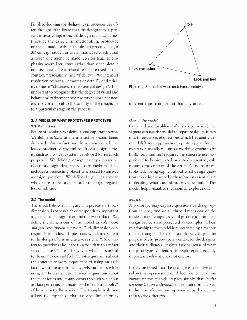
3.2 The model
The model shown in Figure 1 represents a three-dimensional space which corresponds to importantaspects of the design of an interactive artifact. Wedefine the dimensions of the model as role; lookand feel; and implementation. Each dimension cor-responds to a class of questions which are salientto the design of any interactive system. “Role” re-fers to questions about the function that an artifactserves in a user’s life—the way in which it is usefulto them. “Look and feel” denotes questions aboutthe concrete sensory experience of using an arti-fact—what the user looks at, feels and hears whileusing it. “Implementation” refers to questions aboutthe techniques and components through which anartifact performs its function—the “nuts and bolts”of how it actually works. The triangle is drawnaskew to emphasize that no one dimension is
inherently more important than any other.
Goal of the model
Given a design problem (of any scope or size), de-signers can use the model to separate design issuesinto three classes of questions which frequently de-mand different approaches to prototyping. Imple-mentation usually requires a working system to bebuilt; look and feel requires the concrete user ex-perience to be simulated or actually created; rolerequires the context of the artifact’s use to be es-tablished. Being explicit about what design ques-tions must be answered is therefore an essential aidto deciding what kind of prototype to build. Themodel helps visualize the focus of exploration.
Markers
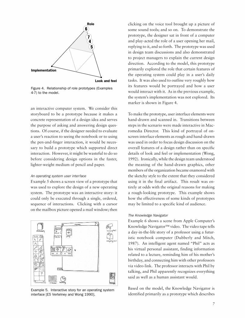
A prototype may explore questions or design op-tions in one, two or all three dimensions of themodel. In this chapter, several prototypes from realdesign projects are presented as examples. Theirrelationship to the model is represented by a markeron the triangle. This is a simple way to put thepurpose of any prototype in context for the designerand their audiences. It gives a global sense of whatthe prototype is intended to explore; and equallyimportant, what it does not explore.
It may be noted that the triangle is a relative andsubjective representation. A location toward onecorner of the triangle implies simply that in thedesigner’s own judgment, more attention is givento the class of questions represented by that cornerthan to the other two.
Implementation
Role
Look and feel
Figure 1. A model of what prototypes prototype.
4
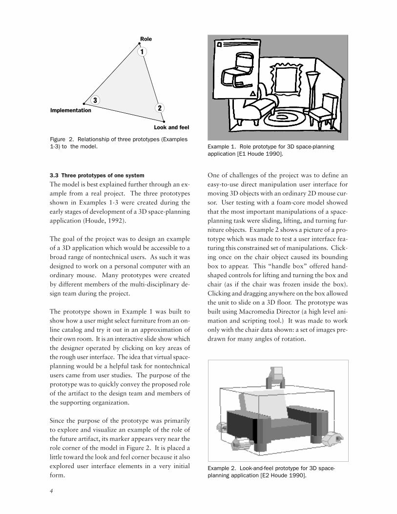
3.3 Three prototypes of one system
The model is best explained further through an ex-ample from a real project. The three prototypesshown in Examples 1-3 were created during theearly stages of development of a 3D space-planningapplication (Houde, 1992).
The goal of the project was to design an exampleof a 3D application which would be accessible to abroad range of nontechnical users. As such it wasdesigned to work on a personal computer with anordinary mouse. Many prototypes were createdby different members of the multi-disciplinary de-sign team during the project.
The prototype shown in Example 1 was built toshow how a user might select furniture from an on-line catalog and try it out in an approximation oftheir own room. It is an interactive slide show whichthe designer operated by clicking on key areas ofthe rough user interface. The idea that virtual space-planning would be a helpful task for nontechnicalusers came from user studies. The purpose of theprototype was to quickly convey the proposed roleof the artifact to the design team and members ofthe supporting organization.
Since the purpose of the prototype was primarilyto explore and visualize an example of the role ofthe future artifact, its marker appears very near therole corner of the model in Figure 2. It is placed alittle toward the look and feel corner because it alsoexplored user interface elements in a very initialform.
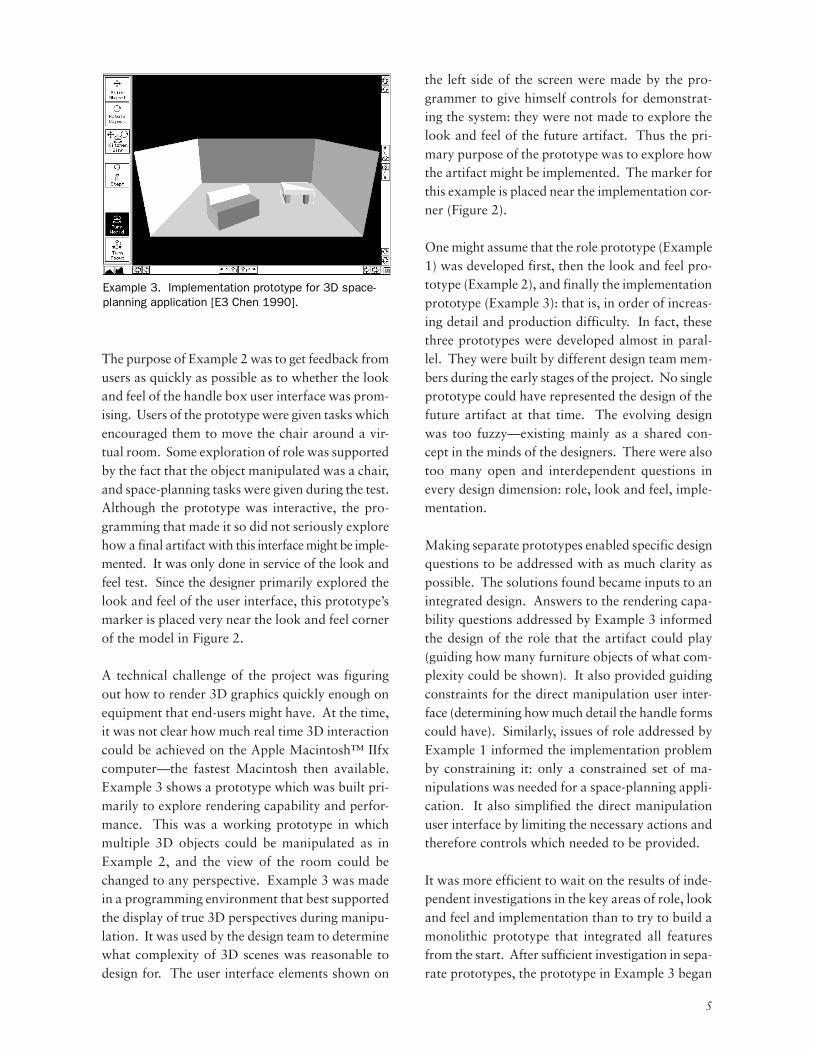
One of challenges of the project was to define aneasy-to-use direct manipulation user interface formoving 3D objects with an ordinary 2D mouse cur-sor. User testing with a foam-core model showedthat the most important manipulations of a space-planning task were sliding, lifting, and turning fur-niture objects. Example 2 shows a picture of a pro-totype which was made to test a user interface fea-turing this constrained set of manipulations. Click-ing once on the chair object caused its boundingbox to appear. This “handle box” offered hand-shaped controls for lifting and turning the box andchair (as if the chair was frozen inside the box).Clicking and dragging anywhere on the box allowedthe unit to slide on a 3D floor. The prototype wasbuilt using Macromedia Director (a high level ani-mation and scripting tool.) It was made to workonly with the chair data shown: a set of images pre-drawn for many angles of rotation.
Role
Look and feel
Implementation
1
23
Figure 2. Relationship of three prototypes (Examples1-3) to the model. Example 1. Role prototype for 3D space-planning
application [E1 Houde 1990].
Example 2. Look-and-feel prototype for 3D space-planning application [E2 Houde 1990].
5
The purpose of Example 2 was to get feedback fromusers as quickly as possible as to whether the lookand feel of the handle box user interface was prom-ising. Users of the prototype were given tasks whichencouraged them to move the chair around a vir-tual room. Some exploration of role was supportedby the fact that the object manipulated was a chair,and space-planning tasks were given during the test.Although the prototype was interactive, the pro-gramming that made it so did not seriously explorehow a final artifact with this interface might be imple-mented. It was only done in service of the look andfeel test. Since the designer primarily explored thelook and feel of the user interface, this prototype’smarker is placed very near the look and feel cornerof the model in Figure 2.
A technical challenge of the project was figuringout how to render 3D graphics quickly enough onequipment that end-users might have. At the time,it was not clear how much real time 3D interactioncould be achieved on the Apple Macintosh™ IIfxcomputer—the fastest Macintosh then available.Example 3 shows a prototype which was built pri-marily to explore rendering capability and perfor-mance. This was a working prototype in whichmultiple 3D objects could be manipulated as inExample 2, and the view of the room could bechanged to any perspective. Example 3 was madein a programming environment that best supportedthe display of true 3D perspectives during manipu-lation. It was used by the design team to determinewhat complexity of 3D scenes was reasonable todesign for. The user interface elements shown on
the left side of the screen were made by the pro-grammer to give himself controls for demonstrat-ing the system: they were not made to explore thelook and feel of the future artifact. Thus the pri-mary purpose of the prototype was to explore howthe artifact might be implemented. The marker forthis example is placed near the implementation cor-ner (Figure 2).
One might assume that the role prototype (Example1) was developed first, then the look and feel pro-totype (Example 2), and finally the implementationprototype (Example 3): that is, in order of increas-ing detail and production difficulty. In fact, thesethree prototypes were developed almost in paral-lel. They were built by different design team mem-bers during the early stages of the project. No singleprototype could have represented the design of thefuture artifact at that time. The evolving designwas too fuzzy—existing mainly as a shared con-cept in the minds of the designers. There were alsotoo many open and interdependent questions inevery design dimension: role, look and feel, imple-mentation.
Making separate prototypes enabled specific designquestions to be addressed with as much clarity aspossible. The solutions found became inputs to anintegrated design. Answers to the rendering capa-bility questions addressed by Example 3 informedthe design of the role that the artifact could play(guiding how many furniture objects of what com-plexity could be shown). It also provided guidingconstraints for the direct manipulation user inter-face (determining how much detail the handle formscould have). Similarly, issues of role addressed byExample 1 informed the implementation problemby constraining it: only a constrained set of ma-nipulations was needed for a space-planning appli-cation. It also simplified the direct manipulationuser interface by limiting the necessary actions andtherefore controls which needed to be provided.
It was more efficient to wait on the results of inde-pendent investigations in the key areas of role, lookand feel and implementation than to try to build amonolithic prototype that integrated all featuresfrom the start. After sufficient investigation in sepa-rate prototypes, the prototype in Example 3 began
Example 3. Implementation prototype for 3D space-planning application [E3 Chen 1990].
6
to evolve into an integrated prototype which couldbe described by a position at the center of ourmodel. A version of the user interface developedin Example 2 was implemented in the prototype inExample 3. Results of other prototypes were alsointegrated. This enabled a more complete user testof features and user interface to take place.
This set of three prototypes from the same projectshows how a design problem can be simultaneouslyapproached from multiple points of view. Designquestions of role, look and feel, and implementa-tion were explored concurrently by the team withthe three separate prototypes. The purpose of themodel is to make it easier to develop and subse-quently communicate about this kind prototypingstrategy.
4. FURTHER EXAMPLES
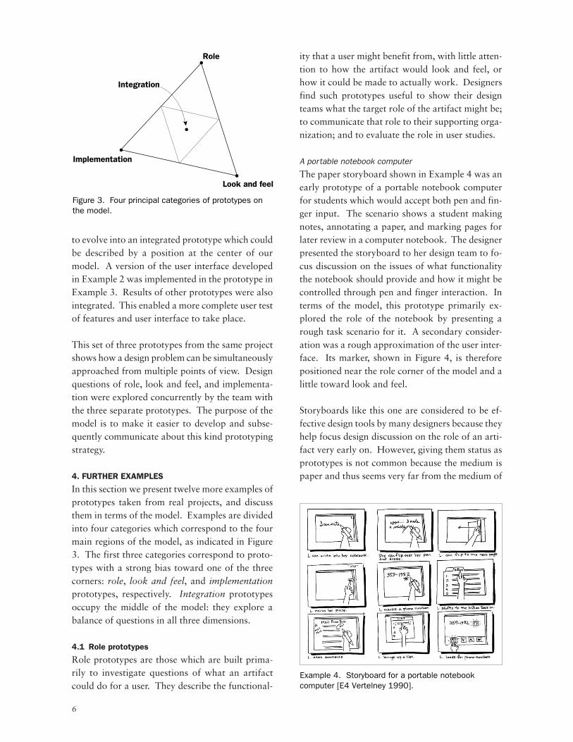
In this section we present twelve more examples ofprototypes taken from real projects, and discussthem in terms of the model. Examples are dividedinto four categories which correspond to the fourmain regions of the model, as indicated in Figure3. The first three categories correspond to proto-types with a strong bias toward one of the threecorners: role, look and feel, and implementationprototypes, respectively. Integration prototypesoccupy the middle of the model: they explore abalance of questions in all three dimensions.
4.1 Role prototypes
Role prototypes are those which are built prima-rily to investigate questions of what an artifactcould do for a user. They describe the functional-
ity that a user might benefit from, with little atten-tion to how the artifact would look and feel, orhow it could be made to actually work. Designersfind such prototypes useful to show their designteams what the target role of the artifact might be;to communicate that role to their supporting orga-nization; and to evaluate the role in user studies.
A portable notebook computer
The paper storyboard shown in Example 4 was anearly prototype of a portable notebook computerfor students which would accept both pen and fin-ger input. The scenario shows a student makingnotes, annotating a paper, and marking pages forlater review in a computer notebook. The designerpresented the storyboard to her design team to fo-cus discussion on the issues of what functionalitythe notebook should provide and how it might becontrolled through pen and finger interaction. Interms of the model, this prototype primarily ex-plored the role of the notebook by presenting arough task scenario for it. A secondary consider-ation was a rough approximation of the user inter-face. Its marker, shown in Figure 4, is thereforepositioned near the role corner of the model and alittle toward look and feel.
Storyboards like this one are considered to be ef-fective design tools by many designers because theyhelp focus design discussion on the role of an arti-fact very early on. However, giving them status asprototypes is not common because the medium ispaper and thus seems very far from the medium of
Look and feel
Integration
Implementation
Role
Figure 3. Four principal categories of prototypes on the model.
Example 4. Storyboard for a portable notebook computer [E4 Vertelney 1990].
7
an interactive computer system. We consider thisstoryboard to be a prototype because it makes aconcrete representation of a design idea and servesthe purpose of asking and answering design ques-tions. Of course, if the designer needed to evaluatea user’s reaction to seeing the notebook or to usingthe pen-and-finger interaction, it would be neces-sary to build a prototype which supported directinteraction. However, it might be wasteful to do sobefore considering design options in the faster,lighter-weight medium of pencil and paper.
An operating system user interface
Example 5 shows a screen view of a prototype thatwas used to explore the design of a new operatingsystem. The prototype was an interactive story: itcould only be executed through a single, ordered,sequence of interactions. Clicking with a cursoron the mailbox picture opened a mail window; then
clicking on the voice tool brought up a picture ofsome sound tools; and so on. To demonstrate theprototype, the designer sat in front of a computerand play-acted the role of a user opening her mail,replying to it, and so forth. The prototype was usedin design team discussions and also demonstratedto project managers to explain the current designdirection. According to the model, this prototypeprimarily explored the role that certain features ofthe operating system could play in a user’s dailytasks. It was also used to outline very roughly howits features would be portrayed and how a userwould interact with it. As in the previous example,the system’s implementation was not explored. Itsmarker is shown in Figure 4.
To make the prototype, user interface elements werehand-drawn and scanned in. Transitions betweensteps in the scenario were made interactive in Mac-romedia Director. This kind of portrayal of on-screen interface elements as rough and hand-drawnwas used in order to focus design discussion on theoverall features of a design rather than on specificdetails of look and feel or implementation (Wong,1992). Ironically, while the design team understoodthe meaning of the hand-drawn graphics, othermembers of the organization became enamored withthe sketchy style to the extent that they consideredusing it in the final artifact. This result was en-tirely at odds with the original reasons for makinga rough-looking prototype. This example showshow the effectiveness of some kinds of prototypesmay be limited to a specific kind of audience.
The Knowledge Navigator
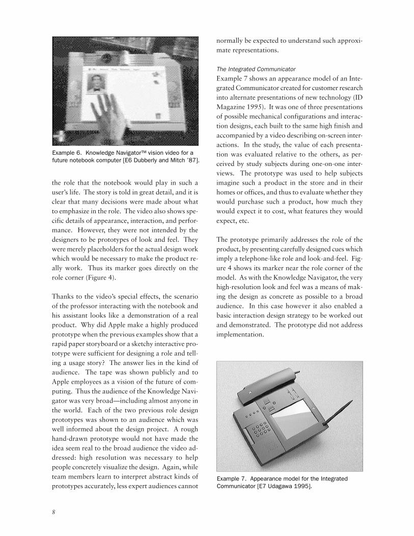
Example 6 shows a scene from Apple Computer’sKnowledge Navigator™ video. The video tape tellsa day-in-the-life story of a professor using a futur-istic notebook computer (Dubberly and Mitch,1987). An intelligent agent named “Phil” acts ashis virtual personal assistant, finding informationrelated to a lecture, reminding him of his mother’sbirthday, and connecting him with other professorsvia video-link. The professor interacts with Phil bytalking, and Phil apparently recognizes everythingsaid as well as a human assistant would.
Based on the model, the Knowledge Navigator isidentified primarily as a prototype which describes
Look and feel
Implementation
Role
4
6
7
5
Figure 4. Relationship of role prototypes (Examples 4-7) to the model.
Example 5. Interactive story for an operating system interface [E5 Vertelney and Wong 1990].
8
the role that the notebook would play in such auser’s life. The story is told in great detail, and it isclear that many decisions were made about whatto emphasize in the role. The video also shows spe-cific details of appearance, interaction, and perfor-mance. However, they were not intended by thedesigners to be prototypes of look and feel. Theywere merely placeholders for the actual design workwhich would be necessary to make the product re-ally work. Thus its marker goes directly on therole corner (Figure 4).
Thanks to the video’s special effects, the scenarioof the professor interacting with the notebook andhis assistant looks like a demonstration of a realproduct. Why did Apple make a highly producedprototype when the previous examples show that arapid paper storyboard or a sketchy interactive pro-totype were sufficient for designing a role and tell-ing a usage story? The answer lies in the kind ofaudience. The tape was shown publicly and toApple employees as a vision of the future of com-puting. Thus the audience of the Knowledge Navi-gator was very broad—including almost anyone inthe world. Each of the two previous role designprototypes was shown to an audience which waswell informed about the design project. A roughhand-drawn prototype would not have made theidea seem real to the broad audience the video ad-dressed: high resolution was necessary to helppeople concretely visualize the design. Again, whileteam members learn to interpret abstract kinds ofprototypes accurately, less expert audiences cannot
normally be expected to understand such approxi-mate representations.
The Integrated Communicator
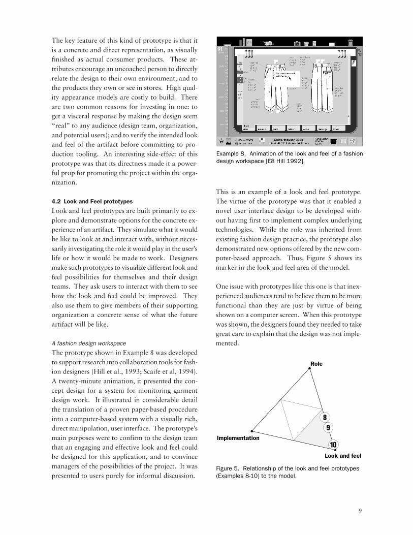
Example 7 shows an appearance model of an Inte-grated Communicator created for customer researchinto alternate presentations of new technology (IDMagazine 1995). It was one of three presentationsof possible mechanical configurations and interac-tion designs, each built to the same high finish andaccompanied by a video describing on-screen inter-actions. In the study, the value of each presenta-tion was evaluated relative to the others, as per-ceived by study subjects during one-on-one inter-views. The prototype was used to help subjectsimagine such a product in the store and in theirhomes or offices, and thus to evaluate whether theywould purchase such a product, how much theywould expect it to cost, what features they wouldexpect, etc.
The prototype primarily addresses the role of theproduct, by presenting carefully designed cues whichimply a telephone-like role and look-and-feel. Fig-ure 4 shows its marker near the role corner of themodel. As with the Knowledge Navigator, the veryhigh-resolution look and feel was a means of mak-ing the design as concrete as possible to a broadaudience. In this case however it also enabled abasic interaction design strategy to be worked outand demonstrated. The prototype did not addressimplementation.
Example 6. Knowledge Navigator™ vision video for a future notebook computer [E6 Dubberly and Mitch ’87].
Example 7. Appearance model for the Integrated Communicator [E7 Udagawa 1995].
9
The key feature of this kind of prototype is that itis a concrete and direct representation, as visuallyfinished as actual consumer products. These at-tributes encourage an uncoached person to directlyrelate the design to their own environment, and tothe products they own or see in stores. High qual-ity appearance models are costly to build. Thereare two common reasons for investing in one: toget a visceral response by making the design seem“real” to any audience (design team, organization,and potential users); and to verify the intended lookand feel of the artifact before committing to pro-duction tooling. An interesting side-effect of thisprototype was that its directness made it a power-ful prop for promoting the project within the orga-nization.
4.2 Look and Feel prototypes
Look and feel prototypes are built primarily to ex-plore and demonstrate options for the concrete ex-perience of an artifact. They simulate what it wouldbe like to look at and interact with, without neces-sarily investigating the role it would play in the user’slife or how it would be made to work. Designersmake such prototypes to visualize different look andfeel possibilities for themselves and their designteams. They ask users to interact with them to seehow the look and feel could be improved. Theyalso use them to give members of their supportingorganization a concrete sense of what the futureartifact will be like.
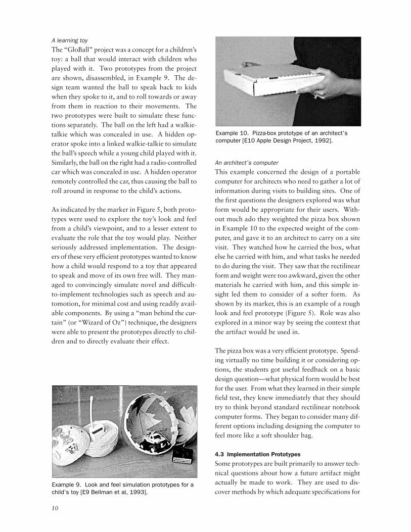
A fashion design workspace
The prototype shown in Example 8 was developedto support research into collaboration tools for fash-ion designers (Hill et al., 1993; Scaife et al, 1994).A twenty-minute animation, it presented the con-cept design for a system for monitoring garmentdesign work. It illustrated in considerable detailthe translation of a proven paper-based procedureinto a computer-based system with a visually rich,direct manipulation, user interface. The prototype’smain purposes were to confirm to the design teamthat an engaging and effective look and feel couldbe designed for this application, and to convincemanagers of the possibilities of the project. It waspresented to users purely for informal discussion.
This is an example of a look and feel prototype.The virtue of the prototype was that it enabled anovel user interface design to be developed with-out having first to implement complex underlyingtechnologies. While the role was inherited fromexisting fashion design practice, the prototype alsodemonstrated new options offered by the new com-puter-based approach. Thus, Figure 5 shows itsmarker in the look and feel area of the model.
One issue with prototypes like this one is that inex-perienced audiences tend to believe them to be morefunctional than they are just by virtue of beingshown on a computer screen. When this prototypewas shown, the designers found they needed to takegreat care to explain that the design was not imple-mented.
Example 8. Animation of the look and feel of a fashion design workspace [E8 Hill 1992].
Role
Look and feel
Implementation
8
10
9
Figure 5. Relationship of the look and feel prototypes (Examples 8-10) to the model.
10
A learning toy
The “GloBall” project was a concept for a children’stoy: a ball that would interact with children whoplayed with it. Two prototypes from the projectare shown, disassembled, in Example 9. The de-sign team wanted the ball to speak back to kidswhen they spoke to it, and to roll towards or awayfrom them in reaction to their movements. Thetwo prototypes were built to simulate these func-tions separately. The ball on the left had a walkie-talkie which was concealed in use. A hidden op-erator spoke into a linked walkie-talkie to simulatethe ball’s speech while a young child played with it.Similarly, the ball on the right had a radio-controlledcar which was concealed in use. A hidden operatorremotely controlled the car, thus causing the ball toroll around in response to the child’s actions.
As indicated by the marker in Figure 5, both proto-types were used to explore the toy’s look and feelfrom a child’s viewpoint, and to a lesser extent toevaluate the role that the toy would play. Neitherseriously addressed implementation. The design-ers of these very efficient prototypes wanted to knowhow a child would respond to a toy that appearedto speak and move of its own free will. They man-aged to convincingly simulate novel and difficult-to-implement technologies such as speech and au-tomotion, for minimal cost and using readily avail-able components. By using a “man behind the cur-tain” (or “Wizard of Oz”) technique, the designerswere able to present the prototypes directly to chil-dren and to directly evaluate their effect.
An architect’s computer
This example concerned the design of a portablecomputer for architects who need to gather a lot ofinformation during visits to building sites. One ofthe first questions the designers explored was whatform would be appropriate for their users. With-out much ado they weighted the pizza box shownin Example 10 to the expected weight of the com-puter, and gave it to an architect to carry on a sitevisit. They watched how he carried the box, whatelse he carried with him, and what tasks he neededto do during the visit. They saw that the rectilinearform and weight were too awkward, given the othermaterials he carried with him, and this simple in-sight led them to consider of a softer form. Asshown by its marker, this is an example of a roughlook and feel prototype (Figure 5). Role was alsoexplored in a minor way by seeing the context thatthe artifact would be used in.
The pizza box was a very efficient prototype. Spend-ing virtually no time building it or considering op-tions, the students got useful feedback on a basicdesign question—what physical form would be bestfor the user. From what they learned in their simplefield test, they knew immediately that they shouldtry to think beyond standard rectilinear notebookcomputer forms. They began to consider many dif-ferent options including designing the computer tofeel more like a soft shoulder bag.
4.3 Implementation Prototypes
Some prototypes are built primarily to answer tech-nical questions about how a future artifact mightactually be made to work. They are used to dis-cover methods by which adequate specifications for
Example 9. Look and feel simulation prototypes for a child’s toy [E9 Bellman et al, 1993].
Example 10. Pizza-box prototype of an architect’s computer [E10 Apple Design Project, 1992].
11
the final artifact can be achieved—without havingto define its look and feel or the role it will play fora user. (Some specifications may be unstated, andmay include externally imposed constraints, suchas the need to reuse existing components or pro-duction machinery.) Designers make implementa-tion prototypes as experiments for themselves andthe design team, to demonstrate to their organiza-tion the technical feasibility of the artifact, and toget feedback from users on performance issues.
A digital movie editor
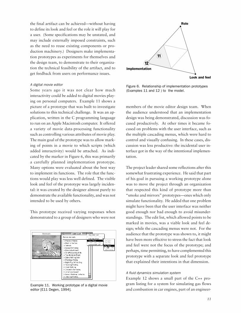
Some years ago it was not clear how muchinteractivity could be added to digital movies play-ing on personal computers. Example 11 shows apicture of a prototype that was built to investigatesolutions to this technical challenge. It was an ap-plication, written in the C programming languageto run on an Apple Macintosh computer. It offereda variety of movie data-processing functionalitysuch as controlling various attributes of movie play.The main goal of the prototype was to allow mark-ing of points in a movie to which scripts (whichadded interactivity) would be attached. As indi-cated by the marker in Figure 6, this was primarilya carefully planned implementation prototype.Many options were evaluated about the best wayto implement its functions. The role that the func-tions would play was less well defined. The visiblelook and feel of the prototype was largely inciden-tal: it was created by the designer almost purely todemonstrate the available functionality, and was notintended to be used by others.
This prototype received varying responses whendemonstrated to a group of designers who were not
members of the movie editor design team. Whenthe audience understood that an implementationdesign was being demonstrated, discussion was fo-cused productively. At other times it became fo-cused on problems with the user interface, such asthe multiple cascading menus, which were hard tocontrol and visually confusing. In these cases, dis-cussion was less productive: the incidental user in-terface got in the way of the intentional implemen-tation.
The project leader shared some reflections after thissomewhat frustrating experience. He said that partof his goal in pursuing a working prototype alonewas to move the project through an organizationthat respected this kind of prototype more than“smoke and mirrors” prototypes—ones which onlysimulate functionality. He added that one problemmight have been that the user interface was neithergood enough nor bad enough to avoid misunder-standings. The edit list, which allowed points to bemarked in movies, was a viable look and feel de-sign; while the cascading menus were not. For theaudience that the prototype was shown to, it mighthave been more effective to stress the fact that lookand feel were not the focus of the prototype; andperhaps, time permitting, to have complemented thisprototype with a separate look and feel prototypethat explained their intentions in that dimension.
A fluid dynamics simulation system
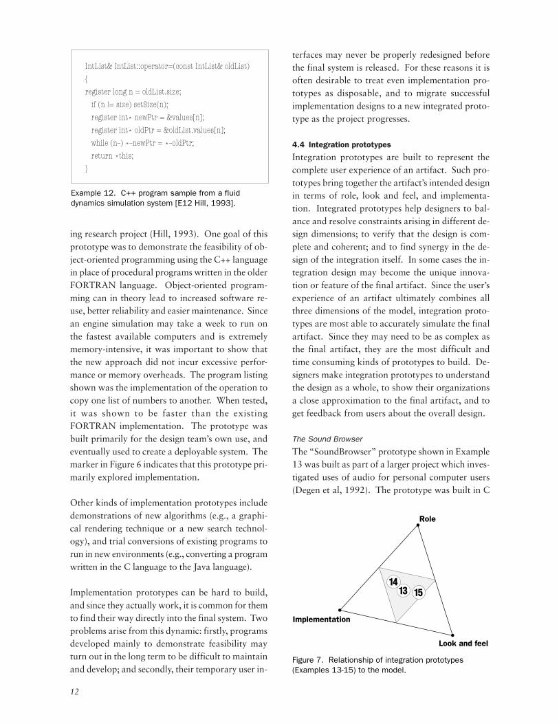
Example 12 shows a small part of the C++ pro-gram listing for a system for simulating gas flowsand combustion in car engines, part of an engineer-
Example 11. Working prototype of a digital movie editor [E11 Degen, 1994].
Role
Look and feel
Implementation12
11
Figure 6. Relationship of implementation prototypes (Examples 11 and 12 ) to the model.
12
ing research project (Hill, 1993). One goal of thisprototype was to demonstrate the feasibility of ob-ject-oriented programming using the C++ languagein place of procedural programs written in the olderFORTRAN language. Object-oriented program-ming can in theory lead to increased software re-use, better reliability and easier maintenance. Sincean engine simulation may take a week to run onthe fastest available computers and is extremelymemory-intensive, it was important to show thatthe new approach did not incur excessive perfor-mance or memory overheads. The program listingshown was the implementation of the operation tocopy one list of numbers to another. When tested,it was shown to be faster than the existingFORTRAN implementation. The prototype wasbuilt primarily for the design team’s own use, andeventually used to create a deployable system. Themarker in Figure 6 indicates that this prototype pri-marily explored implementation.
Other kinds of implementation prototypes includedemonstrations of new algorithms (e.g., a graphi-cal rendering technique or a new search technol-ogy), and trial conversions of existing programs torun in new environments (e.g., converting a programwritten in the C language to the Java language).
Implementation prototypes can be hard to build,and since they actually work, it is common for themto find their way directly into the final system. Twoproblems arise from this dynamic: firstly, programsdeveloped mainly to demonstrate feasibility mayturn out in the long term to be difficult to maintainand develop; and secondly, their temporary user in-
terfaces may never be properly redesigned beforethe final system is released. For these reasons it isoften desirable to treat even implementation pro-totypes as disposable, and to migrate successfulimplementation designs to a new integrated proto-type as the project progresses.
4.4 Integration prototypes
Integration prototypes are built to represent thecomplete user experience of an artifact. Such pro-totypes bring together the artifact’s intended designin terms of role, look and feel, and implementa-tion. Integrated prototypes help designers to bal-ance and resolve constraints arising in different de-sign dimensions; to verify that the design is com-plete and coherent; and to find synergy in the de-sign of the integration itself. In some cases the in-tegration design may become the unique innova-tion or feature of the final artifact. Since the user’sexperience of an artifact ultimately combines allthree dimensions of the model, integration proto-types are most able to accurately simulate the finalartifact. Since they may need to be as complex asthe final artifact, they are the most difficult andtime consuming kinds of prototypes to build. De-signers make integration prototypes to understandthe design as a whole, to show their organizationsa close approximation to the final artifact, and toget feedback from users about the overall design.
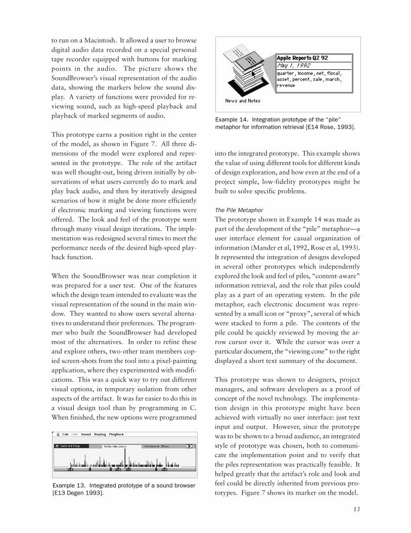
The Sound Browser
The “SoundBrowser” prototype shown in Example13 was built as part of a larger project which inves-tigated uses of audio for personal computer users(Degen et al, 1992). The prototype was built in C
IntList& IntList::operator=(const IntList& oldList)
{
register long n = oldList.size;
if (n != size) setSize(n);
register int* newPtr = &values[n];
register int* oldPtr = &oldList.values[n];
while (n--) *--newPtr = *--oldPtr;
return *this;
}
Example 12. C++ program sample from a fluid dynamics simulation system [E12 Hill, 1993].
Role
Look and feel
Implementation
1314
15
Figure 7. Relationship of integration prototypes (Examples 13-15) to the model.
13
to run on a Macintosh. It allowed a user to browsedigital audio data recorded on a special personaltape recorder equipped with buttons for markingpoints in the audio. The picture shows theSoundBrowser’s visual representation of the audiodata, showing the markers below the sound dis-play. A variety of functions were provided for re-viewing sound, such as high-speed playback andplayback of marked segments of audio.
This prototype earns a position right in the centerof the model, as shown in Figure 7. All three di-mensions of the model were explored and repre-sented in the prototype. The role of the artifactwas well thought-out, being driven initially by ob-servations of what users currently do to mark andplay back audio, and then by iteratively designedscenarios of how it might be done more efficientlyif electronic marking and viewing functions wereoffered. The look and feel of the prototype wentthrough many visual design iterations. The imple-mentation was redesigned several times to meet theperformance needs of the desired high-speed play-back function.
When the SoundBrowser was near completion itwas prepared for a user test. One of the featureswhich the design team intended to evaluate was thevisual representation of the sound in the main win-dow. They wanted to show users several alterna-tives to understand their preferences. The program-mer who built the SoundBrowser had developedmost of the alternatives. In order to refine theseand explore others, two other team members cop-ied screen-shots from the tool into a pixel-paintingapplication, where they experimented with modifi-cations. This was a quick way to try out differentvisual options, in temporary isolation from otheraspects of the artifact. It was far easier to do this ina visual design tool than by programming in C.When finished, the new options were programmed
into the integrated prototype. This example showsthe value of using different tools for different kindsof design exploration, and how even at the end of aproject simple, low-fidelity prototypes might bebuilt to solve specific problems.
The Pile Metaphor
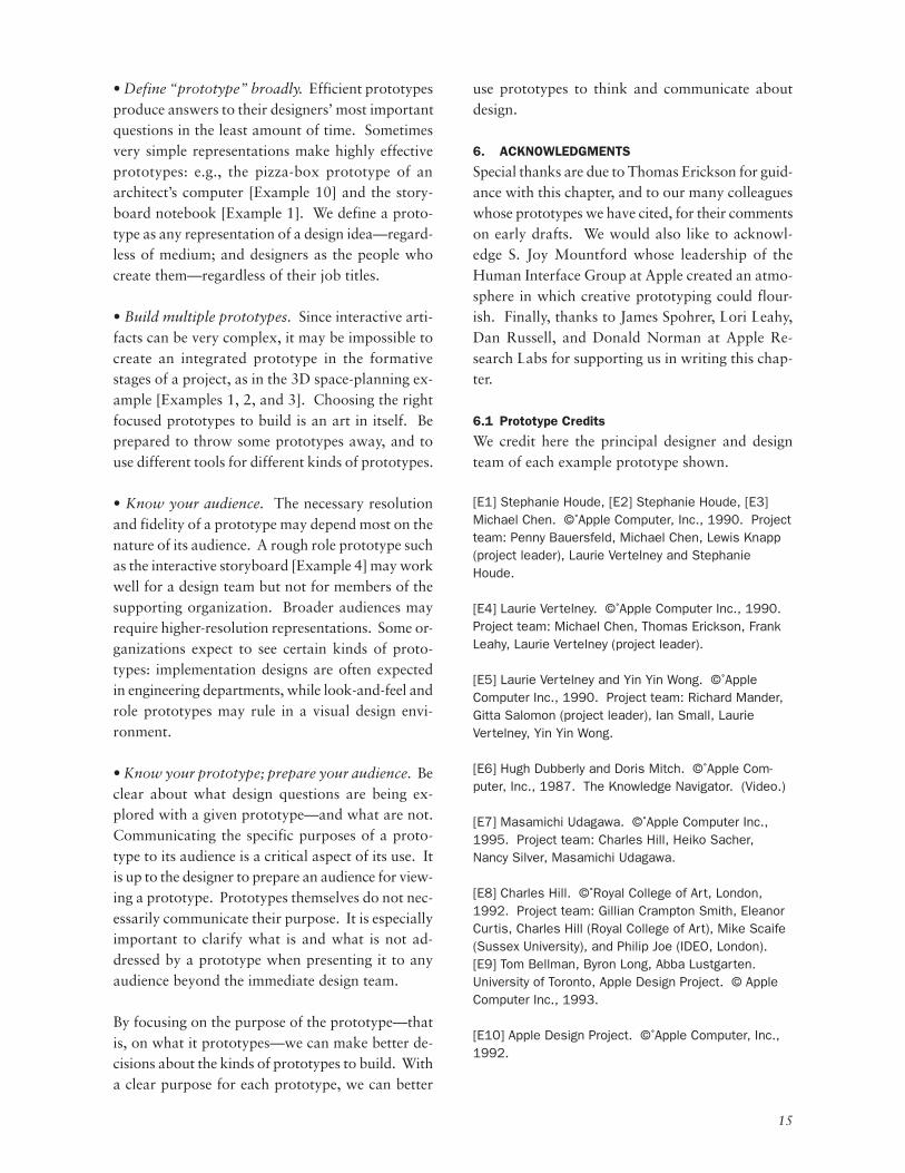
The prototype shown in Example 14 was made aspart of the development of the “pile” metaphor—auser interface element for casual organization ofinformation (Mander et al, 1992, Rose et al, 1993).It represented the integration of designs developedin several other prototypes which independentlyexplored the look and feel of piles, “content-aware”information retrieval, and the role that piles couldplay as a part of an operating system. In the pilemetaphor, each electronic document was repre-sented by a small icon or “proxy”, several of whichwere stacked to form a pile. The contents of thepile could be quickly reviewed by moving the ar-row cursor over it. While the cursor was over aparticular document, the “viewing cone” to the rightdisplayed a short text summary of the document.
This prototype was shown to designers, projectmanagers, and software developers as a proof ofconcept of the novel technology. The implementa-tion design in this prototype might have beenachieved with virtually no user interface: just textinput and output. However, since the prototypewas to be shown to a broad audience, an integratedstyle of prototype was chosen, both to communi-cate the implementation point and to verify thatthe piles representation was practically feasible. Ithelped greatly that the artifact’s role and look andfeel could be directly inherited from previous pro-totypes. Figure 7 shows its marker on the model.
Example 13. Integrated prototype of a sound browser [E13 Degen 1993].
Example 14. Integration prototype of the “pile” metaphor for information retrieval [E14 Rose, 1993].

14
A garment history browser
The prototype in Example 15 was a working sys-tem which enabled users to enter and retrieve snip-pets of information about garment designs via avisually rich user interface (Hill et al, 1993; Scaifeet al, 1994). The picture shows the query tool whichwas designed to engage fashion designers and pro-vide memorable visual cues. The prototype wasdesigned for testing in three corporations with alimited set of users’ actual data, and presented tousers in interviews. It was briefly demonstrated,then users were asked to try queries and enter re-marks about design issues they were currently awareof.
This prototype was the end-result of a progressionfrom an initial focus on role (represented by verbalusage scenarios), followed by rough look and feelprototypes and an initial implementation. Alongthe way various ideas were explored, refined or re-jected. The working tool, built in AllegiantSuperCard™, required two months’ intensive workby two designers. In retrospect the designers hadmixed feelings about it. It was highly motivatingto users to be able to manipulate real user datathrough a novel user interface, and much waslearned about the design. However, the designersalso felt that they had to invest a large amount oftime in making the prototype, yet had only beenable to support a very narrow role compared to thebreadth shown in the animation shown in Example8. Many broader design questions remained unan-swered.
5. SUMMARY
In this chapter, we have proposed a change in thelanguage used by designers to think and talk aboutprototypes of interactive artifacts. Much currentterminology centers on attributes of prototypesthemselves: the tools used to create them, or howrefined-looking or -behaving they are. Yet toolscan be used in many different ways, and resolutioncan be misleading. We have proposed a shift inattention to focus on questions about the design ofthe artifact itself: What role will it play in a userslife? How should it look and feel? How should itbe implemented? The model that we have intro-duced can be used by designers to divide any de-sign problem into these three classes of questions,each of which may benefit from a different approachto prototyping.We have described a variety of prototypes from realprojects, and have shown how the model can beused to communicate about their purposes. Sev-eral practical suggestions for designers have beenraised by the examples:
Example 15. Integrated prototype of a garment history browser [E15 Hill and Kamlish 1992].
Role
Look and feel
Implementation
8
1
2
4
6
7
912
11 13
5
1415
3
10
1.2.3.4.5.6.7.8.9.
10.11.12.13.14.15.
3D space-planning (role)3D space-planning (look and feel)3D space-planning (implementation)Storyboard for portable notebook computerInteractive story, operating system user interfaceVision video, notebook computerAppearance model, integrated communicatorAnimation, fashion design workspaceLook and feel simulation, child’s toyPizza-box, architect’s computerWorking prototype, digital movie editorC++ program listing, fluid dynamics simulationIntegrated prototype, sound browserIntegrated prototype, pile metaphorIntegrated prototype, garment history browser
Figure 8. Relationship of all examples to the model.
15
• Define “prototype” broadly. Efficient prototypesproduce answers to their designers’ most importantquestions in the least amount of time. Sometimesvery simple representations make highly effectiveprototypes: e.g., the pizza-box prototype of anarchitect’s computer [Example 10] and the story-board notebook [Example 1]. We define a proto-type as any representation of a design idea—regard-less of medium; and designers as the people whocreate them—regardless of their job titles.
• Build multiple prototypes. Since interactive arti-facts can be very complex, it may be impossible tocreate an integrated prototype in the formativestages of a project, as in the 3D space-planning ex-ample [Examples 1, 2, and 3]. Choosing the rightfocused prototypes to build is an art in itself. Beprepared to throw some prototypes away, and touse different tools for different kinds of prototypes.
• Know your audience. The necessary resolutionand fidelity of a prototype may depend most on thenature of its audience. A rough role prototype suchas the interactive storyboard [Example 4] may workwell for a design team but not for members of thesupporting organization. Broader audiences mayrequire higher-resolution representations. Some or-ganizations expect to see certain kinds of proto-types: implementation designs are often expectedin engineering departments, while look-and-feel androle prototypes may rule in a visual design envi-ronment.
• Know your prototype; prepare your audience. Beclear about what design questions are being ex-plored with a given prototype—and what are not.Communicating the specific purposes of a proto-type to its audience is a critical aspect of its use. Itis up to the designer to prepare an audience for view-ing a prototype. Prototypes themselves do not nec-essarily communicate their purpose. It is especiallyimportant to clarify what is and what is not ad-dressed by a prototype when presenting it to anyaudience beyond the immediate design team.
By focusing on the purpose of the prototype—thatis, on what it prototypes—we can make better de-cisions about the kinds of prototypes to build. Witha clear purpose for each prototype, we can better
use prototypes to think and communicate aboutdesign.
6. ACKNOWLEDGMENTS
Special thanks are due to Thomas Erickson for guid-ance with this chapter, and to our many colleagueswhose prototypes we have cited, for their commentson early drafts. We would also like to acknowl-edge S. Joy Mountford whose leadership of theHuman Interface Group at Apple created an atmo-sphere in which creative prototyping could flour-ish. Finally, thanks to James Spohrer, Lori Leahy,Dan Russell, and Donald Norman at Apple Re-search Labs for supporting us in writing this chap-ter.
6.1 Prototype Credits
We credit here the principal designer and designteam of each example prototype shown.
[E1] Stephanie Houde, [E2] Stephanie Houde, [E3]Michael Chen. ©␣ Apple Computer, Inc., 1990. Projectteam: Penny Bauersfeld, Michael Chen, Lewis Knapp(project leader), Laurie Vertelney and StephanieHoude.
[E4] Laurie Vertelney. ©␣ Apple Computer Inc., 1990.Project team: Michael Chen, Thomas Erickson, FrankLeahy, Laurie Vertelney (project leader).
[E5] Laurie Vertelney and Yin Yin Wong. ©␣ AppleComputer Inc., 1990. Project team: Richard Mander,Gitta Salomon (project leader), Ian Small, LaurieVertelney, Yin Yin Wong.
[E6] Hugh Dubberly and Doris Mitch. ©␣ Apple Com-puter, Inc., 1987. The Knowledge Navigator. (Video.)
[E7] Masamichi Udagawa. ©␣ Apple Computer Inc.,1995. Project team: Charles Hill, Heiko Sacher,Nancy Silver, Masamichi Udagawa.
[E8] Charles Hill. ©␣ Royal College of Art, London,1992. Project team: Gillian Crampton Smith, EleanorCurtis, Charles Hill (Royal College of Art), Mike Scaife(Sussex University), and Philip Joe (IDEO, London).[E9] Tom Bellman, Byron Long, Abba Lustgarten.University of Toronto, Apple Design Project. © AppleComputer Inc., 1993.
[E10] Apple Design Project. ©␣ Apple Computer, Inc.,1992.
16
[E11] Leo Degen. ©␣ Apple Computer Inc., Projectteam: Leo Degen, Stephanie Houde, Michael Mills(team leader), David Vronay.
[E12] Charles Hill. Doctoral thesis. Project team:Charles Hill, Henry Weller. © University of London,1993.
[E13] Leo Degen. ©␣ Apple Computer Inc., 1193.Project team: Leo Degen, Richard Mander, GittaSalomon (team leader), Yin Yin Wong.
[E14] Daniel Rose. ©␣ Apple Computer, Inc., 1993.Project team: Penny Bauersfeld, Leo Degen, StephanieHoude, Richard Mander, Ian Small, Gitta Salomon(team leader), Yin Yin Wong
[E15] Charles Hill and Stephen Kamlish. © RoyalCollege of Art, London, 1992. Project team: GillianCrampton Smith, Eleanor Curtis, Charles Hill, StephenKamlish (Royal College of Art), and Mike Scaife(Sussex University).
6.2 ReferencesDegen, L., Mander, R., Salomon, G. (1992). Workingwith Audio: Integrating Personal Tape Recorders andDesktop Computers. Human Factors in ComputingSystems: Proc. CHI’92. New York: ACM, pp. 413-418.
Dubberly, H. and Mitch, D. (1987). The KnowledgeNavigator. Apple Computer, Inc. videotape.
Ehn, P., Kyng, M. (1991). Cardboad Computers:Mocking-it-up or Hands-on the Future. Design at Work:Cooperative Design of Computer Systems (ed.Greenbaum, J., and Kyng, M.). Hillsdale, NJ: LawrenceErlbaum. pp. 169-195.
Erickson, T. (1995). Notes on Design Practice: Storiesand Prototypes as Catalysts for Communication.“Envisioning Technology: The Scenario as a Frameworkfor the System Development Life Cycle” (ed. Carroll,J.). Addison-Wesley.
Hill, C. (1993). Software Design for InteractiveEngineering Simulation. Doctoral Thesis. ImperialCollege of Science, Technology and Medicine, Univer-sity of London.
Hill, C., Crampton Smith, G., Curtis, E., Kamlish, S.(1993). Designing a Visual Database for FashionDesigners. Human Factors in Computing Systems:Adjunct Proc. INTERCHI’93. New York, ACM, pp. 49-50.
Houde, S. (1992). Iterative Design of and Interface forEasy 3-D Direct Manipulation. Human Factors inComputing Systems. Proc. CHI’92. New York: ACM, pp.135-142.
I.D.Magazine. Apple’s Shared Conceptual Model. TheInternational Design Magazine: 41st. Annual DesignReview, July-August 1995. USA. pp. 206-207
Kim, S. (1990). Interdisciplinary Collaboration. The Artof Human Computer Interface Design (ed. B. Laurel).Reading, MA: Addison-Wesley. pp.31-44.
Mander, R., Salomon, G., Wong, Y.Y. (1992). A ‘Pile’Metaphor for Supporting Casual Organization ofInformation. Human Factors in Computing Systems:Proc. CHI’92. New York: ACM, pp. 627-634.
Rose, D.E., Mander, R., Oren, T., Ponceleón, D.B.,Salomon, G., Wong, Y. (1993). Content Awareness in aFile System Interface: Implementing the ‘Pile’ Metaphorfor Organizing Information. Research and Developmentin Information Retrieval: Proc. SIGIR. Pittsburgh, PA:ACM, pp. 260-269.
Scaife, M., Curtis, E., Hill, C. (1994). InterdisciplinaryCollaboration: a Case Study of Software Developmentfor Fashion Designers. Interacting with Computers, Vol.6. no. 4, pp. 395-410
Schrage, M. (1996). Cultures of Prototyping. BringingDesign to Software (ed. T. Winograd). USA: ACM Press.pp. 191-205.
Wong, Y.Y. (1992). Rough and Ready Prototypes:Lessons from Graphic Design. Human Factors inComputing Systems: Proc. CHI’92, Posters and Short-Talks, New York: ACM, pp. 83-84.