what do ground motion prediction equations tell us?
TRANSCRIPT

What Do Ground‐Motion Prediction Equations Tell Us About Motions Near
Faults?
David M. BooreGeophysicist
Los Altos, California
Given in the session: Correlations between fault zone structure, earthquakes and generated motion
40th Workshop of the International School of Geophysics on PROPERTIES AND PROCESSES OF CRUSTAL FAULT ZONES
Ettore Majorana Foundation and Centre for Scientific Culture | Erice (TP), Sicily, Italy, May 18‐24, 2013

Short Answer: Not Much
• Contents of talk– NGA‐West 2 Project
• Develop global database– Ground motions near faults
• Inferring fault slip as a function of space and time (source processes)
• Spatial variability (source and propagation processes)– Scaling of ground motions with magnitude at near and intermediate distances (source processes)
• Observed scaling• Simulated scaling
– Stochastic simulations– Application to simulate M scaling
Pacific Earthquake Engineering Research Center (PEER) Next Generation Attenuation Project (NGA‐
West 2) Overview• Goal of Project
– Derive equations for the prediction of various measures of ground shaking from crustal earthquakes in active tectonic regions, as a function of M, R, site condition, etc.
• This is the second of two NGA projects. The results of the first project were published in 2008.

Ground‐Motion Prediction Equations (GMPEs)
• What are GMPEs?– Simple equations giving the mean and standard deviation of measures
of ground motion as a function of magnitude, distance, site conditions, and perhaps other variables
• How are GMPEs used?– Specify motions for seismic design
• Individual structures• Constructing hazard maps used in building codes
– Convenient summary of average M and R variation of motion from many recordings
• Source scaling• Path effects• Site effects

Ground‐Motion Prediction Equations (GMPEs)
, , 30 30ln , , , , , ,E P B JB S B s JB n JB SY F mech F R F V R R V M M M M

PEER NGA‐West 2 Project Overview• Developer Teams (each developed their own GMPEs)
– Abrahamson, Silva, and Kamae (ASK13)– Boore, Stewart, Seyhan, and Atkinson (2 additional members added to
the BA08 team) (BSSA13)– Campbell & Bozorgnia (CB13)– Chiou & Youngs (CY13)– Idriss (I13)
• Supporting Working Groups– Directivity– Site Response– Database– Directionality– Uncertainty– Vertical Component– Adjustment for Damping

PEER NGA‐West 2 Project Overview
• All developers used subsets of data chosen from a common database – Metadata (e.g., magnitude, distance, etc.)– Uniformly processed strong‐motion recordings– U.S. and foreign earthquakes– Active tectonic regions (subduction, stable continental regions are separate projects)
• The database development was a major time‐consuming effort

NGA‐West2 Status
• Most tasks have been completed
– Databases, damping scaling, directivity, directionality, site response
– GMPE final reports
• The GMPEs for horizontal components have been submitted to the USGS:
– Feedback from the USGS National Hazard Maps, internal and external reviewers
• Final reports and the database are now publically available:
– http://peer.berkeley.edu/ngawest2/final‐products/
– http://peer.berkeley.edu/ngawest2/databases/

Predicted and Predictor Variables• Ground‐motion intensity measures
– Peak acceleration (PGA)– Peak velocity (PGV)– Response spectra (PSA, H components combined, similar to geometric mean
PSA of the two components)• Basic predictor variables
– Moment magnitude (M)– Distance (RJB, RRUP)– Site characterization (VS30)
• Additional predictor variables– Basin depth– Hanging wall/foot wall– Depth to top of rupture– Fault dip– Event class (mainshock/aftershock)– etc.

• NGA‐West1 models did not explicitly include directivity of ground motion
• Five directivity models have been developed– Wide‐band and narrow‐
band models
• This effort will continue in 2013‐14
-117 -116.5 -116Longitude
34
34.5
35
Latit
ude
Epicenter
Lucerne Valley 136 cm/sec
Forward directivity region
Backward directivity region
Rupturepropagation
Joshua Tree 43 cm/sec
1992 Landers, CA, EQ
Directivity

What are response spectra?
• The maximum response of a suite of single degree of freedom (SDOF) damped oscillators for a range of resonant periods, plotted as a function of the resonant period for a given input motion
• Why useful? Buildings can often be represented as SDOF oscillators, so a response spectrum provides the motion of an arbitrary structure to a given input motion, which is useful in engineering design

Period = 0.2 s
0.5 s 1.0 s
Courtesy of J. Bommer

Response Spectrum
Courtesy of J. Bommer

Surface projection of rupture
Station
Epicenter
Hypocenter High-stress zone
Fault rupture
D1
D2
D3D4
D5
Most Commonly Used:
D4 = RRUP
D5 = RJB (0.0 for station over the fault)
Distance Measures

Kyoshin Net (K‐NET) Japanese strong motion
networkhttp://www.k‐net.bosai.go.jp
• 1000 digital instruments installed after the Kobe earthquake of 1995
• free field stations with an average spacing of 25 km
• velocity profile of each station up to 20 m by downholemeasurement
• data are transmitted to the Control Center and released on Internet in 3‐4 hours after the event
• more than 2000 accelerogramsrecorded in 4 years
There are now many networks of strong‐motion recorders in the world. Here is an example:

PEER NGA‐West 2 Strong‐Motion Database
• >600 (173) worldwide shallow crustal events from active tectonic regions
• >21,000 (3551) recordings (mostly 3‐components each) uniformly processed strong motion stations
• M 3.0 (4.2) to 7.9 (7.9)
Blue = Previous NGA
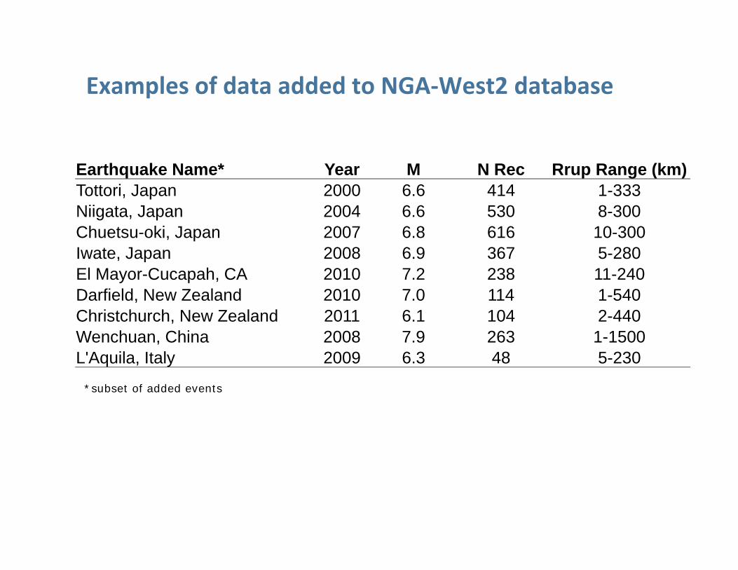
Earthquake Name* Year M N Rec Rrup Range (km)Tottori, Japan 2000 6.6 414 1-333Niigata, Japan 2004 6.6 530 8-300Chuetsu-oki, Japan 2007 6.8 616 10-300Iwate, Japan 2008 6.9 367 5-280El Mayor-Cucapah, CA 2010 7.2 238 11-240Darfield, New Zealand 2010 7.0 114 1-540Christchurch, New Zealand 2011 6.1 104 2-440Wenchuan, China 2008 7.9 263 1-1500L'Aquila, Italy 2009 6.3 48 5-230
*subset of added events
Examples of data added to NGA‐West2 database

How the NGA‐West 2 Project Fits into this Talk
• The database created in the project contains uniformly processed data and carefully screened metadata (e.g., VS30) that can be used in studies of near‐fault ground motions– Amplitude variations– Polarization complexities
• The GMPEs provide a summary of many data (used for studies of source, path, and site effects)– Scaling with magnitude

Ground Motions Near Faults
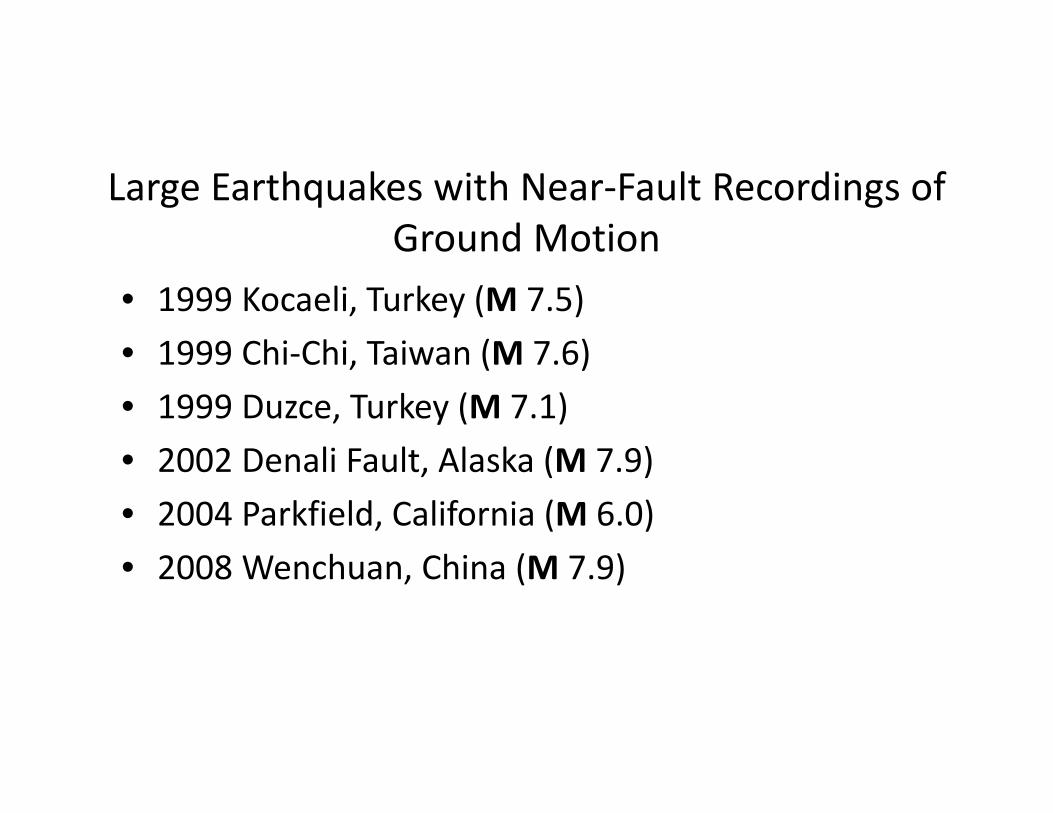
Large Earthquakes with Near‐Fault Recordings of Ground Motion
• 1999 Kocaeli, Turkey (M 7.5)• 1999 Chi‐Chi, Taiwan (M 7.6)• 1999 Duzce, Turkey (M 7.1)• 2002 Denali Fault, Alaska (M 7.9)• 2004 Parkfield, California (M 6.0)• 2008 Wenchuan, China (M 7.9)

Numbers of Records in PEER NGA‐West 2 Database for 3 Near‐fault Distance Ranges
Event Type M RJB<2 km RJB<5 km RJB<10 km
Kocaeli SS 7.6 2 3 4
Chi‐Chi RS 7.5 18 23 42
Duzce SS 7.1 2 7 9
Denali SS 7.9 1 1 1
Parkfield SS 6.0 19 41 63
Wenchuan RS 7.9 5 6 6
Note that being close is not the same as being in the fault zone. This is particularly true for non‐vertical faults (usually RS, NS faults). It is also true that a station can be in the Fault Damage Zone, and yet RJB could be large. The dataset available to me did not have a variable indicating whether or not a station was in the FDZ.

From Bouchon et al. (2002)
Near‐fault records are usually used in determinations of fault slip as a function of space and time: the 1999 Kocaeli, Turkey (M 7.5)
2004 Parkfield, California (M 6.0)From Liu et al. (2006)
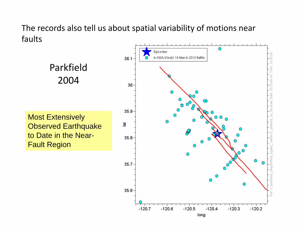
Most Extensively Observed Earthquake to Date in the Near-Fault Region
Parkfield2004
The records also tell us about spatial variability of motions near faults

Shakal et al. (2006a)
Coherent polarization and spatial variations in amplitude for displacements

Sources of Variability
• Nonuniform fault slip• Site geology• Fault zone effects• See Antonio Rovelli’s talk for more discussion of the sources of variability

Most Extensively Observed Earthquake to Date in the Near-Fault Region
Parkfield2004
The records also tell us about spatial variability of motions near faults

Spatial variations depend on frequency content of the motion—for a given station separation, expect more variability for higher frequency motions

Most Extensively Observed Earthquake to Date in the Near-Fault Region
Parkfield2004
The records also tell us about spatial variability of motions near faults
UPSAR

From Fletcher et al. (1992)
USGS Parkfield Dense Seismograph Array (UPSAR) Recordings of the 2004 ParkfieldEarthquake
Less variability for longer period motion

T=0.1 s

T=2.0 s

Recordings near the Calaveras Fault Zone

From Spudich and Olsen (2001)
Gilroy #6 on a ridge to the east of the fault, with Vs30=663 m/s
Coyote Lake downstream in the fault zone with Vs30=295 m/s

1993 (M 5.1): abutment, downstream
CL79 (M 5.7): abutment
Displacement frequencies ~0.5 to 2 Hz

S‐wave portion for 1993 is more fault normal than fault parallel, in contrast to MH84 at the abutment station
MH84
1993 abutment 1993 downstream

1984 Morgan Hill
Gilroy #6 (fault normal)
Abutment
Gilroy #6
Sources of Variability of Amplitude and Polarization
• Nonuniform fault slip• Site geology• Fault zone effects

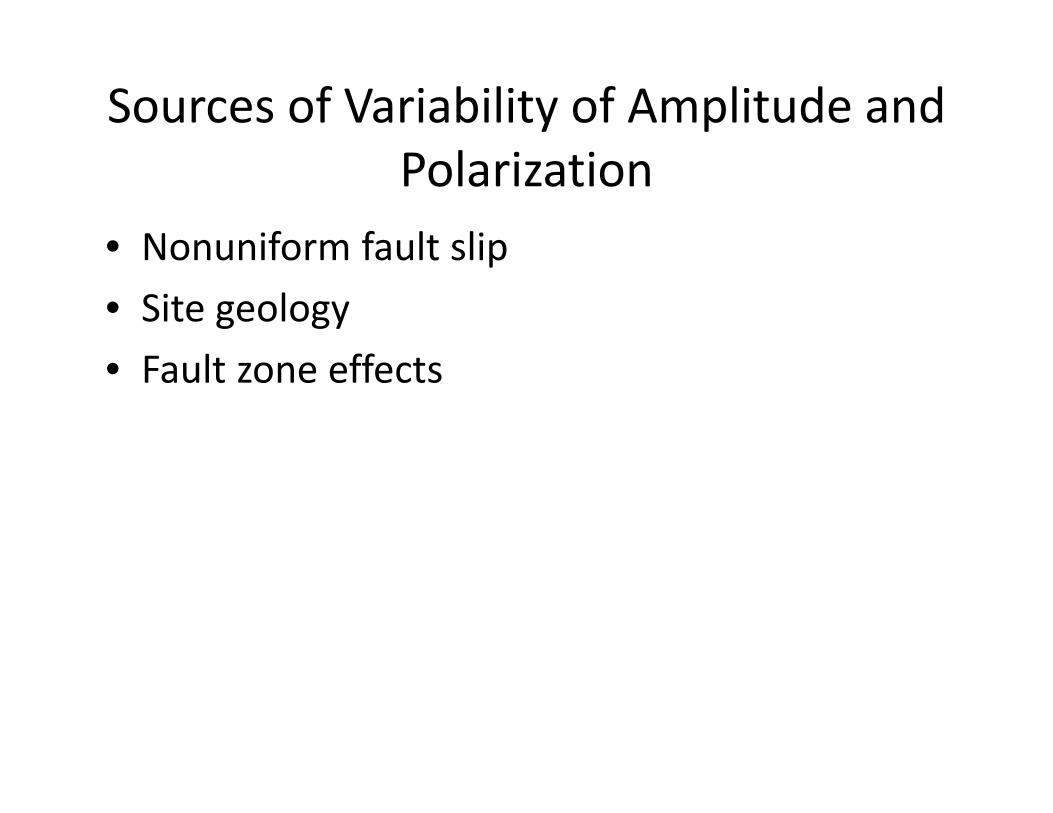
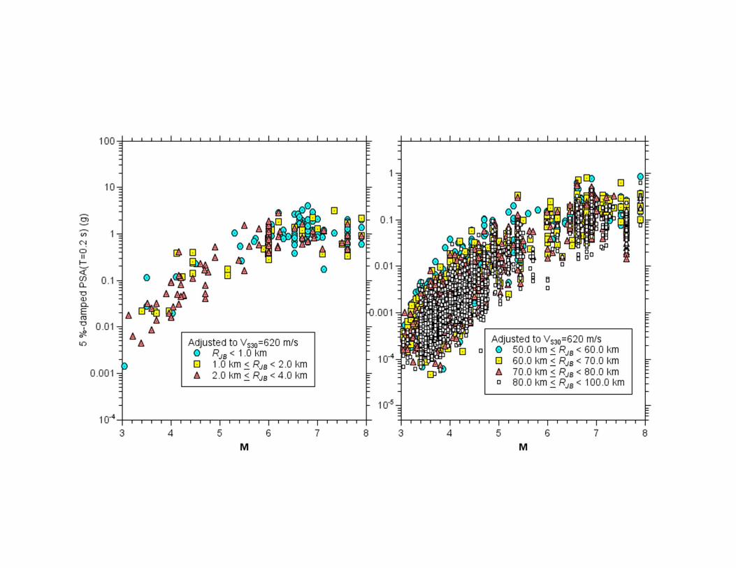
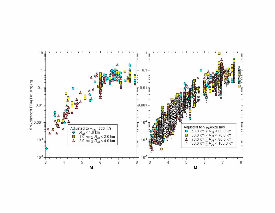
Turning now to GMPEs:Number of records used for BSSA13 base‐case GMPEs

C:\nga_w2\report4peer_figures\ psa_vs_rjb.14mar13.m_3‐4_4‐5_5‐6_6‐7_7‐8_vs_760_mech_1(ss)_t_0.2_1.0_3.0_6.0.draw
• SS only, adjusted to VS30= 760 m/s
• Large scatter (M‐dependent)
• For single M, near‐source saturation
• Distance decay a function of period and M(not so obvious for M)
• For single RJB, saturation for large M, close distances, short periods
• M scaling greater for long periods

• For single M, near‐source saturation
• Distance decay a function of period and M (not so obvious for M)
• For single RJB, saturation for large M, close distances, short periods
• M scaling greater for long periods

• Site amplification generally larger for long periods than short periods
• Nonlinear effects for large M(implying large “rock” motions) lead to reduction of motions at short periods

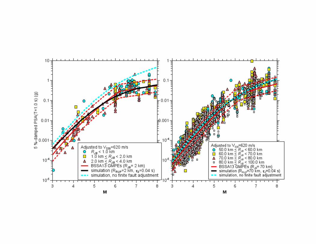
Scaling of Motions with Magnitude at Near and Intermediate Distances
• Data• Data plus GMPEs• Data plus simulations

SIMULATIONS
• Stochastic method fundamentals• Finite‐fault modification• Source/path/site params for the simulations

• Deterministic modelling of high-frequency waves not possible (lack of Earth detail and computational limitations)
• Treat high-frequency motions as filtered white noise (Hanks & McGuire , 1981).
• combine deterministic target amplitude obtained from simple seismological model and quasi-random phaseto obtain high-frequency motion. Try to capture the essence of the physics using simple functional forms for the seismological model. Use empirical data when possible to determine the parameters.
Stochastic modelling of ground-motion: Point Source

0.1 1.0 10 1000.01
0.1
1.0
10
100
Frequency (Hz)
Four
ier
acce
lera
tion
spec
trum
(cm
/sec
)
f0 f0
M = 7.0
M = 5.0
-200
0
200
20 25 30 35 40 45
-200
0
Time (sec)
Acc
eler
atio
n(c
m/s
ec2 )
M = 7.0
M = 5.0
R=10 km; =70 bars; hard rock; fmax=15 Hz
File
:C:\m
etu_
03\s
imul
atio
n\M
5M7_
spec
tra_a
ccel
.dra
w;
Dat
e:20
03-0
9-17
;Ti
me:
20:0
7:43
Basis of stochastic method
Radiated energy described by the spectra in the top graph is assumed to be distributed randomly over a duration given by the addition of the source duration and a distant-dependent duration that captures the effect of wave propagation and scattering of energy
These are the results of actual simulations; the only thing that changed in the input to the computer program was the moment magnitude (5 and 7)

Target amplitude spectrum
Deterministic function of source, path and site characteristics represented by separate multiplicative filters
Earthquakesource
Propagation path
Site response
Instrument or ground
motion
0 0( , , ) ( , ) ( , ) ( ) ( )Y M R f E M f P R f G f I f
THE KEY TO THE SUCCESS OF THE MODEL LIES IN BEING ABLE TO DEFINE FOURIER ACCELERATION SPECTRUM AS F(M, DIST)

Finite‐Fault Adjustments

Parameters used in simulations are from Atkinson and Silva (2000)


Summary
• In spite of the large dataset, there are relatively few records from crustal fault zones in the large NGA dataset
• Fault zone records show significant variability in amplitude and polarization, but unraveling the causes of this variability is difficult
• The magnitude‐to‐magnitude increase of motions at a given distance becomes smaller as magnitude increases, with short‐period motions at near‐fault distances having almost complete saturation for large magnitudes
• The magnitude scaling is largely reproduced by simple models of the source and path effects

Thank you