what are these? - diwakar yagyasen personal web...
TRANSCRIPT


What are these?
• The Intel 8253 and 8254 are Programmable Interval Timers (PITs), which perform timing and counting functions. They are found in all IBM PC compatibles.
• 82C54 which is a superset of the 82C53

8253 functions( General overview )
• The Intel 8253 is a programmable counter / timer chip designed for use as an Intel microcomputer peripheral. It uses nMOS technology with a single +5V supply and is packaged in a 24-pin plastic DIP.
• It is organized as 3 independent 16-bit counters, each with a counter rate up to 2 MHz. All modes of operation are software programmable.
• The 82C54 is pin compatible with the HMOS 8254, and is a superset of the 8253.
• Six programmable timer modes allow the 82C54 / 8253 to be used as an event counter, elapsed time indicator, programmable one-shot, and in many other applications.

Block diagram of an 8253 programmable interval timer
8253/4 Block Diagram … details
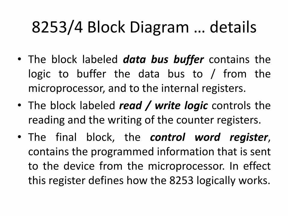
• The block labeled data bus buffer contains thelogic to buffer the data bus to / from themicroprocessor, and to the internal registers.
• The block labeled read / write logic controls thereading and the writing of the counter registers.
• The final block, the control word register,contains the programmed information that is sentto the device from the microprocessor. In effectthis register defines how the 8253 logically works.

8253/4 Block Diagram … details
• Each counter in the block diagram has 3 logical lines connected to it.
– Two of these lines, clock and gate, are inputs.
– The third, labeled OUT is an output.
• The function of these lines changes and depends on how the device is initialized or programmed.

PIN configuration

RD WR A0 A1 function
COUNTER 0 1 0 0 0 Load counter 0
0 1 0 0 Read counter 0
COUNTER 1 1 0 0 1 Load counter 1
0 1 0 1 Read counter 1
COUNTER 2 1 0 1 0 Load counter 2
0 1 1 0 Read counter 2
MODE WORD or CONTROL WORD
1 0 1 1 Write mode word
- - 0 1 1 1 No-operation
Internal 8253 registers:Here is a list of the internal 8253 registers that will program the internal counters of the 8253:
Internal 8253 registers:
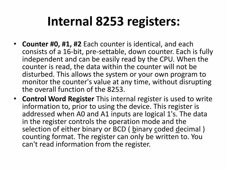
• Counter #0, #1, #2 Each counter is identical, and each consists of a 16-bit, pre-settable, down counter. Each is fully independent and can be easily read by the CPU. When the counter is read, the data within the counter will not be disturbed. This allows the system or your own program to monitor the counter's value at any time, without disrupting the overall function of the 8253.
• Control Word Register This internal register is used to write information to, prior to using the device. This register is addressed when A0 and A1 inputs are logical 1's. The data in the register controls the operation mode and the selection of either binary or BCD ( binary coded decimal ) counting format. The register can only be written to. You can't read information from the register.
Control Word Register
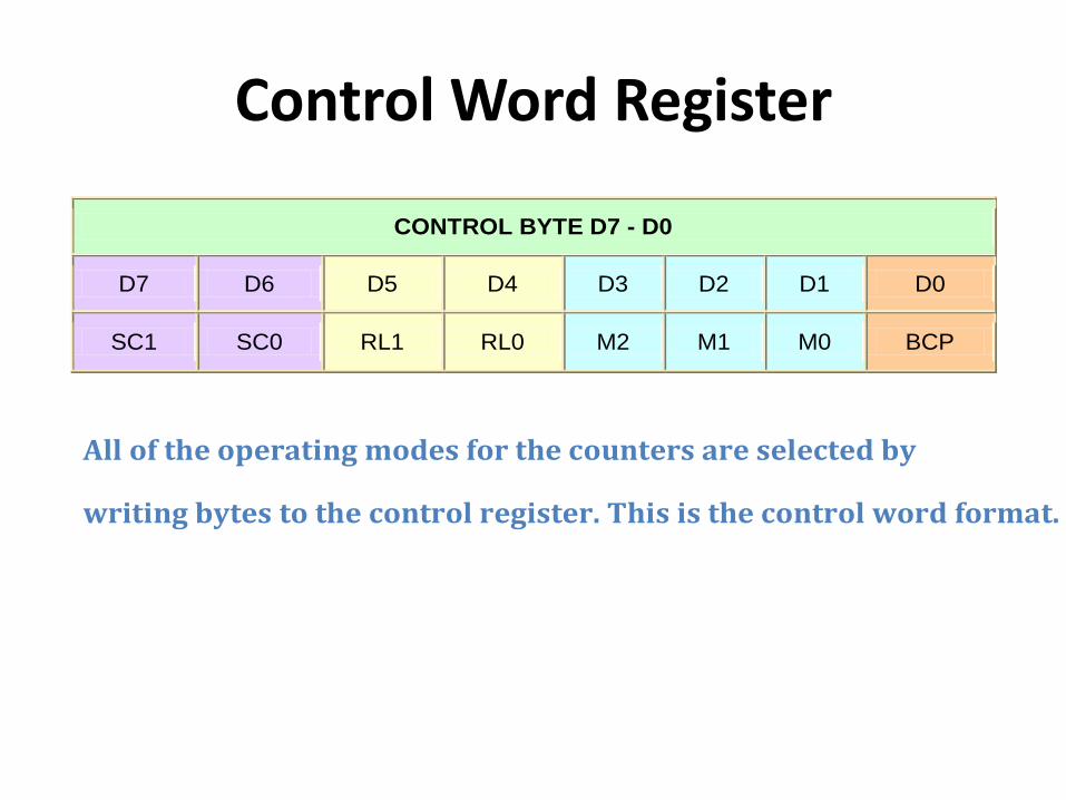
CONTROL BYTE D7 - D0
D7 D6 D5 D4 D3 D2 D1 D0
SC1 SC0 RL1 RL0 M2 M1 M0 BCP
All of the operating modes for the counters are selected by
writing bytes to the control register. This is the control word format.

D7 SC1
D6 SC0
Counter Select
0 0 counter 0
0 1 counter 1
1 0 counter 2
1 1 illegal value
Bits D7 and D6 are labeled SC1 and SC0. These bits
select the counter to be programmed, it is necessary
to define, using the control bits D7 and D6, which
counter is being set up.
Once a counter is set up, it will remain that way
until it is changed by another control word.
8253 Control Word Register
8253 Operation Modes
•The timer has three counters, called channels. Eachchannel can be programmed to operate in one of sixmodes. Once programmed, the channels can performtheir tasks independently.•The D3, D2, and D1 bits of the Control Word set theoperating mode of the timer. There are 6 modes in total;for modes 2 and 3, the D3 bit is ignored, so the missingmodes 6 and 7 are aliases for modes 2 and 3. Notice that,for modes 0, 2, 3 and 4, GATE must be set to HIGH toenable counting. For mode 5, the rising edge of GATEstarts the count. For details on each mode, see thereference links.

Mode 0 (000): Interrupt on Terminal Count
• In this mode, the counter will start counting from the initial COUNT value loaded into it, down to 0. Counting rate is equal to the input clock frequency.
• The OUT pin is set low after the Control Word is written, and counting starts one clock cycle after the COUNT programmed. OUT remains low until the counter reaches 0, at which point OUT will be set high until the counter is reloaded or the Control Word is written.The Gate signal should remain active high for normal counting.If Gate goes low counting get terminated and current count is latched till Gate pulse goes high again.
Mode 1 (001): Hardware-Triggered One Shot
• In this mode 8253 can be used as monostable multivibrator. GATE input is used as trigger input.
• OUT will be initially high. OUT will go low on the CLK pulse following a trigger to begin the one-shot pulse, and will remain low until the Counter reaches zero. OUT will then go high and remain high until the CLK pulse after the next trigger.
• After writing the Control Word and initial count, the Counter is armed. A trigger results in loading the Counter and setting OUT low on the next CLKpulse, thus starting the one-shot pulse. An initial count of N will result in a one-shot pulse N CLK cycles in duration.
• The one-shot is retriggerable, hence OUT will remain low for N CLK pulses after any trigger. The one-shot pulse can be repeated without rewriting the same count into the counter. GATE has no effect on OUT. If a new count is written to the Counter during a oneshot pulse, the current one-shot is not affected unless the counter is retriggered. In that case, the Counter is loaded with the new count and the oneshot pulse continues until the new count expires.
Mode 2 (X10): Rate Generator
• In this mode, the device acts as a divide-by-n counter, which is commonly used to generate a real-time clock interrupt.
• Like other modes, counting process will start the next clock cycle after COUNT is sent. OUT will then remain high until the counter reaches 1, and will go low for one clock pulse. OUT will then go high again, and the whole process repeats itself.
• The time between the high pulses depends on the preset count in the counter's register, and is calculated using the following formula:
• Value to be loaded into counter = • Note that the values in the COUNT register range from n to 1; the
register never reaches zero.

Mode 3 (X11): Square Wave Generator
• This mode is similar to mode 2. However, the duration of the high and low clock pulses of the output will be different from mode 2.
• Suppose n is the number loaded into the counter (the COUNT message), the output will be n/2 high for counts, and low for n/2 counts, if n is even.
• high for (n+1)/2 counts, and low (n-1)/2 for counts, if n is odd.

Mode 4 (100): Software Triggered Strobe
• After Control Word and COUNT is loaded, the output will remain high until the counter reaches zero. The counter will then generate a low pulse for 1 clock cycle (a strobe) - after that the output will become high again.

Mode 5 (101): Hardware Triggered Strobe
• This mode is similar to mode 4. However, the counting process is triggered by the GATE input.
• After receiving the Control Word and COUNT, the output will be set high. Once the device detects a rising edge on the GATE input, it will start counting. When the counter reaches 0, the output will go low for one clock cycle - after that it will become high again, to repeat the cycle on the next rising edge of GATE.
