wha characteristic elements of ignition mechanisms - … · 1 as early as 1965 industrial oxygen...
TRANSCRIPT

Page 1 of 13
WHA Characteristic Elements of Common Ignition Mechanisms Particle Impact:
Heat generated when small particles strike a material with sufficient velocity to ignite the particle and/or the material.
Most efficient mechanism to directly ignite metals.
1. Particulate Assume the presence of particles unless system is extremely clean or well filtered.
- Typical filtration levels for high-pressure GOX systems are nominally 10 microns (NASA RP 1113).
- Typical filtration levels for industrial systems are 30 to 100 mesh (~600 to 150 microns1, CGA G4.4).
2. High velocities (~>100 ft/s, 30 m/s) - Valves, orifices, regulators, etc. - High ∆P = high velocity - ∆P approximately 2:1 (or greater) = sonic velocity - ∆P approximately 3% across component = velocity > 150 ft/sec
3. Impact point and residence time (45° – 90° most severe) - Residence time increases with sudden changes in gas flow direction - The greater the angular change, the more efficient the target for particle impact. - CGA G4.4 uses a radius to diameter ratio of 1.5 to discriminate between
impingement and non-impingement on formed elbows, or efficient impact and non-efficient impact
4. Flammable target2 and flammable particle (except for some metals like aluminum which can be ignited by impact from an inert particle e.g., dirt).
Example: A 90° elbow or Tee placed directly downstream of a flow control valve OR the
seat and outlet portion of a throttling in-line globe valve. The pressure differential that can be tolerated to control high gas velocities is significantly smaller than for control of downstream heat of compression3. Even small pressure differentials across components can generate gas velocites in excess of those recommended for various
1 As early as 1965 industrial oxygen suppliers recognized that particle impact and filtration were key elements of a safe oxygen system. W. E. Groves of the Union Carbide Corporation published a paper, “Safe Handling of Large Quantities of Gaseous Oxygen in Steel Pipelines”, where he reported that in particle impact testing relevant to pipelines, “iron particles could be ignited only when composed of a full range of particle sizes from 0 to 40 microns”. From the test data he concluded that, “It would be desirable at all times to use filters which would remove particles larger than 40 microns (350 mesh). Such filters, however, are not practical at present in large sizes.” (due to expense). Consequently, the industrial gas industry filters typically with 30 to 100 mesh and also rigorously reduces gas velocities to avoid particle impact hazards. 2 The flammability of the metal target is determined from comparing the metal’s burn pressure per ASTM G124 testing and the pressure at the impact point. 3 Castillo, D. G. and Werley, B. L., “Eliminating Bypass Valves in Selected Oxygen Systems,” Flammability and Sensitivity of Materials in Oxygen-Enriched Atmospheres: Eighth Volume, ASTM STP 1319, W. T. Royals, T. C. Chou, and T. A. Steinberg, Eds., American Society for Testing and Materials, 1997.

Page 2 of 13
metals in oxygen service4. Equation 1 can be used to estimate the downstream gas pressure for a given upstream pressure and maximum downstream gas velocity, assuming an ideal gas and isentropic flow2:
PD = PT / [(VD2/2gcKRTD) + 1]K (Equation 1)
where: PD = Downstream pressure (absolute) PT = Source pressure (absolute) VD = Maximum gas velocity downstream gc = Dimensional constant (1 kg/N s2 or 4636 lb in2/lbfs
2 ft) K = γ/(γ-1) where γ is the ratio of specific heats Cp/Cv (γ = 1.4 for O2) R = Specific Gas Constant (260 N-m/kg °K or 48 ft lbf/ lbm °R) TD = Temperature downstream (absolute)
Figure 1 below shows the maximum gas velocity versus pressure differential considering isentropic flow for gaseous oxygen, based on the equation shown above. Even with only a 1.5-percent differential pressure, gas velocity exceeds the 45 m/s (150 ft/s) minimum velocity required to ignite particles in particle impact experiments5.
Figure 1 – Maximum oxygen gas velocity produced by pressure differentials,
4 CGA G-4.4-2003 (4th Edition)/IGC doc 13/02, Oxygen Pipeline Systems, Compressed Gas Association, Inc., Chantilly, VA, European Industrial Gases Association , Brussels.
5 Williams, R. E., Benz, F. J., and McIlroy, K., “Ignition of Steel Alloys by Impact of Low-Velocity Iron/Inert Particles in Gaseous Oxygen,” Flammability and Sensitivity of Materials in Oxygen-Enriched Atmospheres, ASTM STP 986, D. W. Schroll, Ed., American Society for Testing and Materials, Philadelphia, 1988, pp. 72-84.
0
6
12
18
24
30
37
43
49
55
61
67
73
79
85
91
0
20
40
60
80
100
120
140
160
180
200
220
240
260
280
300
0 0.5 1 1.5 2 2.5 3 3.5 4 4.5 5
Do
wn
stre
am V
elo
city
(m
/s)
Do
wn
stre
am V
elo
city
(ft
/s)
Percent Differential Pressure (%)

Page 3 of 13
assuming isentriopic flow Compression Heating (Near-Adiabatic Compression):
Heat generated when a gas is compressed from a low to a high pressure. Most efficient mechanism to directly ignite nonmetals.
1. Pressure ratio: n
n
ifif PPTT1
, where n = Cp/Cv = 1.4 for oxygen (see below)
2. Rapid pressurization - Ball valve, cylinder valves, plug valves
3. Exposed nonmetal proximate to dead end
Example: A polymer-lined flex hose attached to a cylinder valve and a manifold isolation valve with no distance pieces implemented.
Equation 2 shows a formula6 for the theoretical maximum temperature (Tf) that can be developed when pressurizing a gas rapidly from one pressure and temperature to an elevated pressure without heat transfer:
Tf/T i = [ ]Pf/Pi ( )n1 /n (Equation 2) where: Tf = final temperature, abs, Ti = initial temperature, abs, Pf = final pressure, abs, Pi = initial pressure, abs, and
n = Cp
Cv = 1.40 for oxygen (Equation 3)
where: Cp = specific heat at constant pressure, and Cv = specific heat at constant volume.
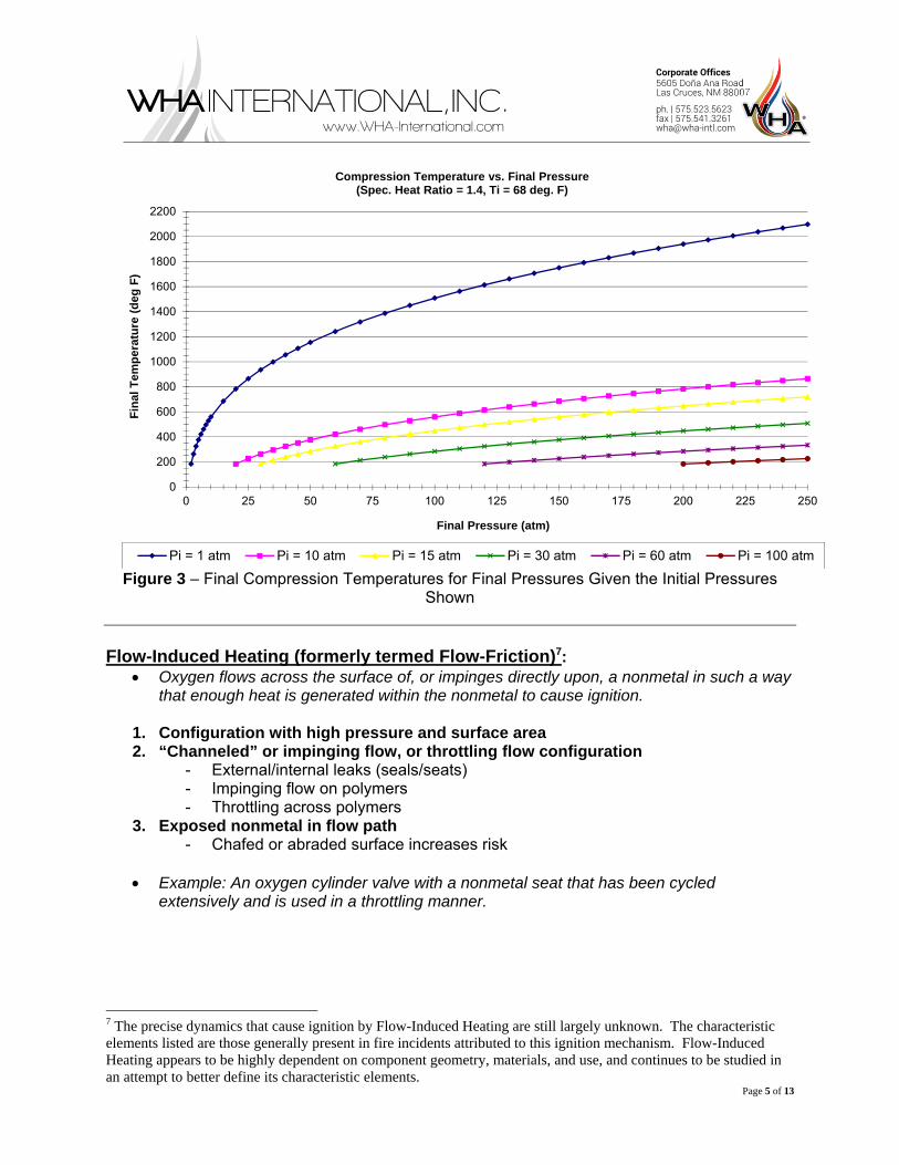
Table 1 gives the theoretical temperatures (Tf) that could be obtained by compressing oxygen adiabatically from an initial temperature (Ti) of 20°C and initial pressure (Pi) of one standard atmosphere to the pressures shown. Figures 3 and 4 show these final temperatures graphically as a function of Pressure Ratio and Final Pressure (Pf), respectively. Table 1 and Figure 2 show that pressure ratios as low as 10 (for example rapidly pressurizing a system from ambient to 1 MPa (145 psia)) can theoretically produce temperatures that exceed the autogenous ignition temperatures (AIT) of many nonmetals or contaminants in oxygen systems (based upon the AIT of various materials per ASTM G72). Figure 3 shows how increasing the downstream pressure prior to the compression event lowers the final temperature.
6 Formula shown is based upon isentropic flow relations for a ideal gas

Page 4 of 13
TABLE 1: Theoretical Maximum Temperature Obtained when Compressing Oxygen Adiabatically from 20°C and One Standard Atmosphere to various Pressures
Final Pressure, Pf Pressure Ratio Pf/Pi
Final Temperature, Tf kPa PSIA °C °F 345 50 3.4 143 289 690 100 6.8 234 453 1000 145 9.9 291 556 1379 200 13.6 344 653 2068 300 20.4 421 789 2758 400 27.2 480 896 3447 500 34.0 530 986 5170 750 51.0 628 1163 6895 1000 68.0 706 1303 10000 1450 98.6 815 1499 13790 2000 136.1 920 1688 27579 4000 272.1 1181 2158 34474 5000 340.1 1277 2330 100000 14500 986.4 1828 3322 1,000,000 145000 9863.9 3785 6845
Figure 2 – Final Compression Temperatures for Pressure Ratios
0
200
400
600
800
1000
1200
1400
1600
1800
2000
2200
2400
0 20 40 60 80 100 120 140 160 180 200 220 240 260 280 300 320 340 360 380
Fin
al T
emp
erat
ure
(d
eg F
)
Pressure Ratio (Pf/Pi)
Compression Temperatures Vs. Pressure RatiosTi = 68 deg F, Pi = 14.7 psia
Page 5 of 13
Figure 3 – Final Compression Temperatures for Final Pressures Given the Initial Pressures
Shown Flow-Induced Heating (formerly termed Flow-Friction)7:
Oxygen flows across the surface of, or impinges directly upon, a nonmetal in such a way that enough heat is generated within the nonmetal to cause ignition.
1. Configuration with high pressure and surface area 2. “Channeled” or impinging flow, or throttling flow configuration
- External/internal leaks (seals/seats) - Impinging flow on polymers - Throttling across polymers
3. Exposed nonmetal in flow path - Chafed or abraded surface increases risk
Example: An oxygen cylinder valve with a nonmetal seat that has been cycled
extensively and is used in a throttling manner.
7 The precise dynamics that cause ignition by Flow-Induced Heating are still largely unknown. The characteristic elements listed are those generally present in fire incidents attributed to this ignition mechanism. Flow-Induced Heating appears to be highly dependent on component geometry, materials, and use, and continues to be studied in an attempt to better define its characteristic elements.
0
200
400
600
800
1000
1200
1400
1600
1800
2000
2200
0 25 50 75 100 125 150 175 200 225 250
Fin
al T
emp
erat
ure
(d
eg F
)
Final Pressure (atm)
Compression Temperature vs. Final Pressure(Spec. Heat Ratio = 1.4, Ti = 68 deg. F)
Pi = 1 atm Pi = 10 atm Pi = 15 atm Pi = 30 atm Pi = 60 atm Pi = 100 atm

Page 6 of 13
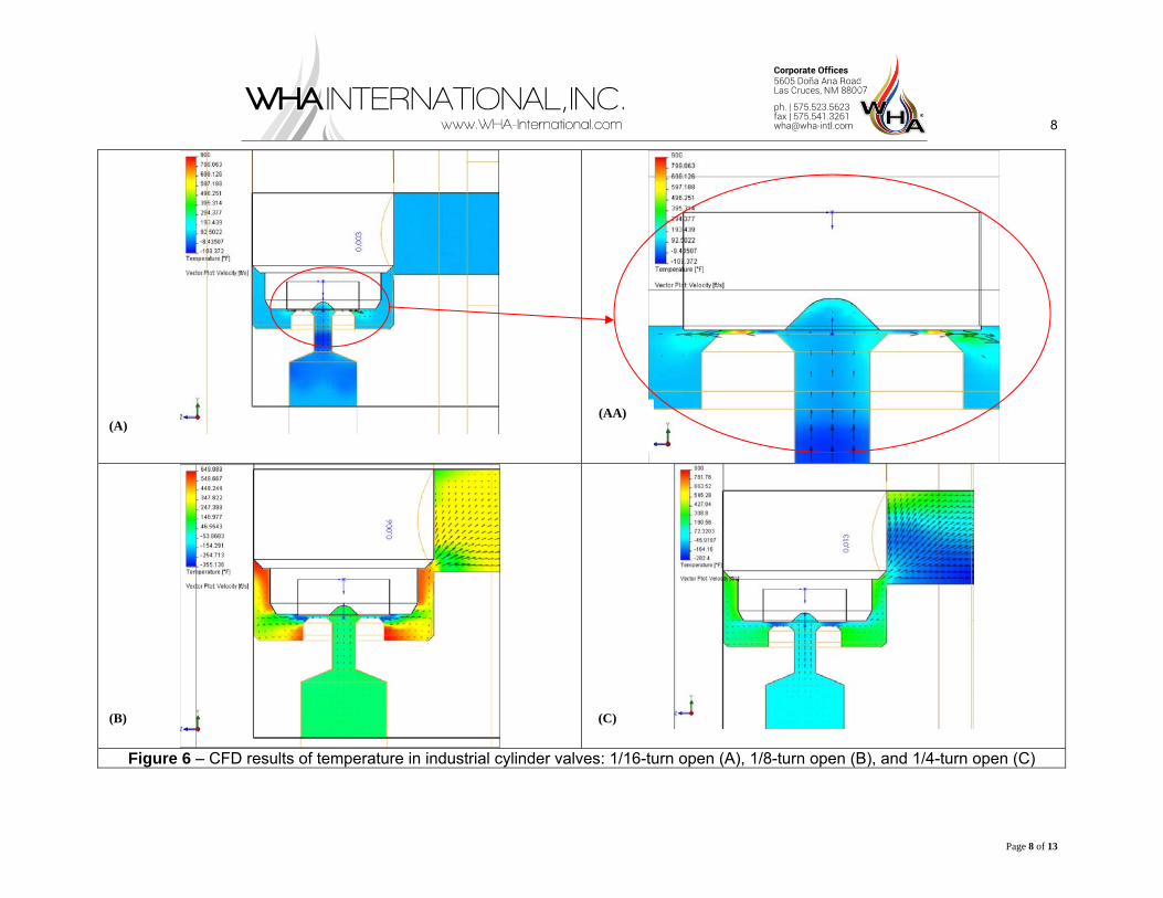
WHA studied this theory of flow-induced heating on the specific geometry of a cylinder valve seat by developing a CFD flow model of the valve. Figures 4, 5, and 6 show the predicted pressure, velocity, and temperature plots, respectively, of flow from the cylinder impinging upon the seat and throttling past the seat to the valve exhaust. The seat area was modeled at three different opening distances: 1/16-turn open, 1/8-turn open, and 1/4-turn open. Though these results are predicted values and not yet validated, they show a significant change in fluid conditions and flow dynamics across the cylinder valve seat during the initial opening sequences. The results also reveal that flow impingement directly on the plastic seat creates the potential for high stagnation pressures and temperatures. Further, the throttling effect of the gas across the seat creates a large temperature gradient across the seat radius that could induce thermal stresses and lead to further seat deformation. The stagnation temperatures on the seat predicted by the model may suggest that flow-induced heating of the seat in this particular valve geometry may contribute to the ignitions experienced in oxygen cylinder valves. Considering the substantial fire history with industrial oxygen cylinder valves and WHA’s study of these incidents, including the CFD models shown below, WHA has expanded the contributing elements for flow-induced heating as they relate to an industrial cylinder valve to include the following:
1. Stagnation temperature rise Direct impingement of flow on polymer seat
2. Vortex flow Especially bad for highly extruded seats
3. Mechanical friction Higher for heavily loaded or overloaded seats
4. Resonance in materials during flow More severe for finely divided material resulting from repeated overload
5. Flow impingement Surface friction/erosion of flow across seat elements

Page 7 of 13
Figure 4 – CFD results of pressure in industrial cylinder valves: 1/16-turn open (A), 1/8-turn open (B), and 1/4-turn open (C)
Figure 5 – CFD results of velocity in industrial cylinder valves: 1/16-turn open (A), 1/8-turn open (B), and 1/4-turn open (C)
(A) (B) (C)
(A) (B) (C)
8
Page 8 of 13
Figure 6 – CFD results of temperature in industrial cylinder valves: 1/16-turn open (A), 1/8-turn open (B), and 1/4-turn open (C)
(A) (AA)
(B) (C)

Page 9 of 13
Mechanical Impact:
Single or repeated impacts on a material with sufficient force to ignite it.
1. Single, large impact or repeated impact loading 2. Nonmetal at point of impact.
- In laboratory testing this mechanism is generally only active in nonmetals - Aluminum, magnesium, and titanium alloys in thin cross-sections as well as some
solders have been ignited experimentally. However, in these alloys, mechanical failure (which introduces additional ignition mechanisms) will likely precede or at minimum coincide with, mechanical impact ignitions in liquid oxygen (LOX).
3. Special caution for impact on certain materials in LOX: - Porous hydrocarbon materials such as asphalt, wood, and leather, can become
shock-sensitive in LOX and react explosively when impacted.
Example: A high-pressure relief valve “chattering,” imparting repeated impacts on a nonmetal seat, leading to ignition of the seat, OR leather work glove soaked in LOX and exposed to impact of a wrench
Galling and Friction:
Heat generated by the rubbing of two or more parts together.
1. Two or more rubbing surfaces - Metal-to-metal contact is generally most severe as it destroys protective oxide
surfaces or coatings and exposes fresh metal. 2. High speed and high loads more severe
- Normal load/pressure x Rotational velocity/frequency (Pv product) 3. One or more flammable rubbing surface (material)
Example: A reciprocating compressor with worn piston ring seals causing rubbing of the
piston on the internal cylinder wall. Electrical Arc:
Electrical arcing through ungrounded or short-circuited powered components causing ignition of a flammable material.
1. Ungrounded or short-circuited power source
Motor brushes, electrical control equipment, instrumentation, lighting, etc. 2. Flammable materials capable of being ignited by the electrical arc or spark
Examples: An insulated electrical heater element undergoing a short circuit arcing through
its sheath to a combustible material, OR exposed wiring from electrical cables in an oxygen enriched compressor housing

Page 10 of 13
Static Discharge: Accumulated static charge on a nonconducting surface discharges with enough energy to
ignite material receiving the discharge.
1. Electrostatic charge accumulation - On surface of an insulator (e.g., non-metal) or throughout the body of an electrically
isolated (ungrounded) conductor (e.g., metal) - Requires friction between solid surfaces or fast separation of non-conducting
liquids/solids (including rapid separation of phases (i.e., relief valve discharge of gas from liquid system)
- Very dependent on humidity (≥ 65 % - charge bleeding due to surface layer of liquid) 2. Configuration to discharge
- Two surfaces of differing electrostatic potentials 3. Discharge energy sufficient for ignition
- 2 isolated conductors > conductor/insulator >> 2 insulators 4. Flammable material receiving or exposed to discharge arc energy
Examples:
1. Large diameter ball valves with nonmetal upstream and downstream seats, where the ball/stem can become electrically isolated from the body and a charge differential develop between the ball and body from the ball rubbing against the large surface area nonmetal seat. Ignition energy possible but not yet confirmed/measured Probability increased with particulate in flow stream
2. Non-metallic gas hoses or polymers exposed to gas flow Difficult to accumulate charge with pure clean dry gas flow on polymeric
hoses or softgoods. Possible with particulate or liquid contaminants e.g., NASA KSC Teflon-lined flexhoses – pinhole leaks
3. Human body (charge accumulator or capacitor) Typical size can accumulate 15 to 35 K volts Produces a 25 – 40 mJ spark in less than 25 % humidity Sufficient energy to ignite vapor fuel/oxygen mixtures e.g., gasoline pump Difficult to ignite solid or liquid non-metallic fuel/oxygen mixtures
4. Medical regulators venting during removal Fires from two-stage regulators that trap pressure and vent when removed
from cylinder valves Particulate carried from filter from backflow of oxygen Potential difference developed between regulator and cylinder valve due to
electrical isolation developed by CGA 870 seal 5. Bed sheets and clothing in hyperbaric chambers
Questionable ignition probability since energy is low and usually categorized as “brush discharge”
Must contain sufficient energy to vaporize solid before ignition

Page 11 of 13
Resonance: Acoustic oscillations within resonant cavities that cause rapid temperature rise (more serve
if particles are present).
1. Specially “tuned” resonance cavity. - The requirements include a throttling device such as a nozzle, orifice, regulator, or
valve directing a sonic gas jet into a cavity, or closed-end tube. 2. Acoustic resonance phenomena, often audible.
- The distance between the throttling device and the closed end affects the frequency of acoustic oscillations in the cavity, similar to a pipe organ with a closed end, due to the interference of incident and reflecting sound waves. This distance also ultimately affects the temperature produced in the cavity. Higher harmonic frequencies have been shown to produce higher system temperatures. The resonant frequency has been shown to be a function of pipe diameter and pressure ratio.
3. Flammable particulate or contaminant debris at closed end. - Particulate or debris residing at the closed end of the cavity can self-ignite due to
the high gas temperatures produced by this phenomenon, or they can vibrate, or resonate, and their collisions generate sufficient heat to self-ignite.
Example: Resonance igniters for solid or liquid rocket fuel: Gaseous oxygen flows through a
sonic nozzle and directly into a resonance cavity, heating the gas and solid or liquid fuel. When the gas reaches the auto-ignition temperature of the fuel, ignition occurs and a flame jet is emitted from the chamber.
Promoted Ignition/Kindling Chain:
Heat from the ignition and combustion of a more flammable material igniting a less flammable material.
Similar to kindling chain of paper, twigs, and logs.
1. Contaminants present - Usually nonmetals, such as hydrocarbons and/or small polymers
2. Ignition mechanism - Starts kindling chain - Adiabatic compression and flow-induced heating common
3. Flammable materials to kindle/propagate
Example: hydrocarbon oil contaminates the inlet of a welding regulator causing ignition followed by burn out when the attached cylinder valve is opened.
Thermal Ignition:
Heating a material (either by external or self-heating means) in an oxidizing atmosphere to a temperature sufficient to cause spontaneous ignition (also known as self-ignition). In thermal ignition testing, the spontaneous ignition temperature, or autogenous ignition temperature, is normally used to rate material compatibility with oxygen as well as evaluate a material’s ease of ignition. The ignition temperature of a given material is generally dependent on the effect of its thermal properties, including thermal conductivity, heat of

Page 12 of 13
oxidation, and thermal diffusivity, as well as other parameters such as geometry and environmental conditions.
1. An external heat source capable of heating a given material to its self-ignition
temperature in a given environment. 2. A material with a spontaneous ignition temperature below the temperature created
by the heat source in the given configuration and environment.
Example: A resistive element heater in a thermal runaway fault condition causing oxygen-wetted materials in the proximity to spontaneously ignite.
Other Ignition Mechanism Examples
1. Fresh metal exposure 2. Personnel smoking and open flames 3. Shock waves from tank rupture 4. Fragments from bursting vessels 5. Welding 6. Exhaust from thermal combustion engine 7. Lightning
Page 13 of 13
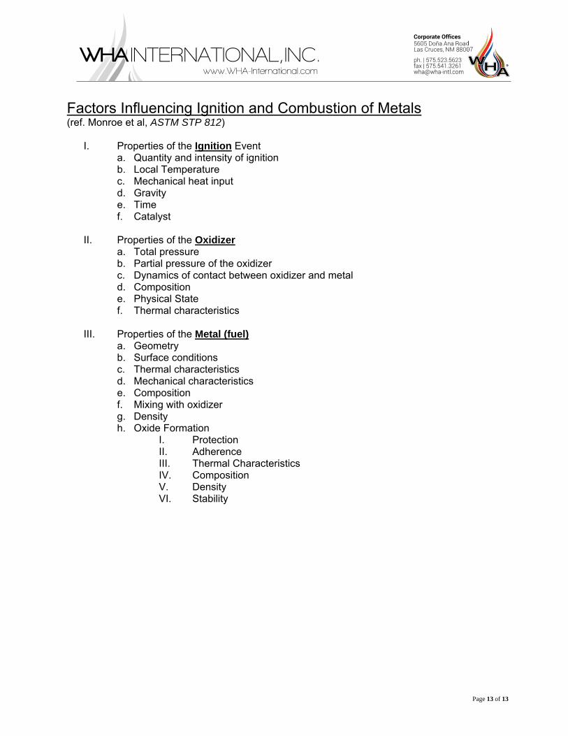
Factors Influencing Ignition and Combustion of Metals (ref. Monroe et al, ASTM STP 812)
I. Properties of the Ignition Event a. Quantity and intensity of ignition b. Local Temperature c. Mechanical heat input d. Gravity e. Time f. Catalyst
II. Properties of the Oxidizer
a. Total pressure b. Partial pressure of the oxidizer c. Dynamics of contact between oxidizer and metal d. Composition e. Physical State f. Thermal characteristics
III. Properties of the Metal (fuel)
a. Geometry b. Surface conditions c. Thermal characteristics d. Mechanical characteristics e. Composition f. Mixing with oxidizer g. Density h. Oxide Formation
I. Protection II. Adherence III. Thermal Characteristics IV. Composition V. Density VI. Stability