westinghouse rts series lock installation and operational
TRANSCRIPT

Page 1
Westinghouse RTS Series Lock Installation and Operational Manual
Overview The RTS Series delivers uncompromising commercial-grade quality. This lock is a true workhorse, tested to over 2 million duty cycles. The RTS has a 3-hour UL fire-rated latch and a free-wheeling clutch. The outdoor portion is weather resistant. When used with the MS1 Management System (sold separately) you can configure all of your locks and manage all user information from a central system administrator’s position. The RTS provides you with the versatility to manage access control using both fingerprint recognition and PIN codes. The MS1 access control and audit trail features track exactly who has been in your facility and when. Please read all documentation carefully before installation & use. This manual details all installation procedures. Manufacturer and/or Distributors of the RTS will not be responsible for any damages caused by incorrect installation or mishandling of the lock. Any such damages will void manufacturer’s warranty. Further information on the warranty terms and conditions can be found in Appendix A to this manual. Important: The RTS outside (front) unit has been designed for weather exposure. Exposure of the inside (back) unit to the elements will void manufacturer warranty. See Appendix A to this manual for further information under “Warranty Terms and Conditions”

Page 2
Features Up to 1,000 finger print and/or PIN enrollments Backlit PIN keypad for easy use at night Rugged Zamak 5 cast enclosure with Satin Chrome finish 5 second access time before door re-locks Heavy Duty components rated to over 2 million cycles UL-Listed, ANSI Grade 2 tubular latch with 3-hour UL fire-rating
Backset (2 3/8″ or 2 3/4t
Commercial grade 6-pin rim cylinder (removable) with SC4 keyway (3 keys included) Free-wheeling clutch design IP56 tested ensures resistance to humidity, dust, and rain Rated for -40°F to 150°F ADA compliant handle is non-handed for right or left hand installation Timed Unlock Mode Support (“TUMS”) opens and closes lock on pre-defined
schedule Battery life provides minimum 1,800 openings1 Low battery alert Non-volatile memory not lost when batteries removed or replaced RS485 compatible for serial communication Normally open contacts to activate relays 2 programing modes
- At the lock using the LCD and keypad - Via the MS1 Management System
Easy to Delete Individual users Access Control features:
- Open Mode - Timed Lock Access - Timed User Access - Import Records - Export Records
2 Year Limited Warranty
Specifications Fingerprint sensor - CMOS Optical, 4rd Generation high resolution, backlit, coated Verification Type
1 to N (PIN or fingerprint only) 1 to 1 (User ID + FP or PIN)
Scanning Time < 1 second Recognition Time < 1 second/user False Accept Rate (FAR) < .001% False Reject Rate (FRR) < .01% Dimensions: 1.5" D x 3" W x 9.5" L Weight: 9 Lbs.
1 May vary based on actual conditions

Page 3
Door Thickness: 1 1/2" to 2" compatible with most standard wood, metal or fiber glass doors: not for use on doors that use exotic woods or glass doors MS1 Management System This Manual describes how to program the RTS Series manually at each lock. To take full advantage of the RTS features you must use the MS1 Management System for programming. This software enables you to program one or more locks from a PC. The MS1 is sold separately and has a separate installation manual. Contact your distributor for more pricing and availability. You can also go to www.westinghousesecurity.com for more information about the MS1.

Page 4
Contents
.............................................................................. 1
Section 1: Tools/Parts ................................................................................................... 6
Section 2: Pre-installation ............................................................................................ 7 2.1 Mark and bore holes on the door .......................................................................................... 7 2.2 Setting/Installing the latch and strike plate ..........................................................................10 2.3 Removing handles and re-installing for Right/Left handed configuration .............................11
Section 3: Installation ................................................................................................. 12 3.1 Installing the Outside Unit ...................................................................................................12 3.2 Installing the Fixing Plate ....................................................................................................14 3.3 Removing Battery Cover .....................................................................................................15 3.4 Installing the Inside Unit ......................................................................................................15 3.5 Installing the Antenna (for the RTS-Z and RTS-PZ) ............................................................17
Section 4: Power Options ........................................................................................... 18 4.1 Installing the Batteries .........................................................................................................18
Section 5: Hard Reset ................................................................................................. 19
Section 6: Unlocking (RTS and RTS-Z only) ............................................................. 20 6.1 1: N Mode (Enrolled user with an enrolled fingerprint) .........................................................20 6.2 1:N Mode (User with a registered PIN Code) ......................................................................21 6.3 1:1 Mode with an enrolled fingerprint...................................................................................21 6.4 1:1 Mode with a registered PIN Code ..................................................................................22 6.5 With the override keys .........................................................................................................23
Section 7: Lock Programming Instructions .............................................................. 24 7.1 Menu Buttons ......................................................................................................................25 7.2 Date/Time ...........................................................................................................................26 7.3 Sensitivity (RTS & RTS-Z) ...................................................................................................30 7.4 Match Mode ........................................................................................................................31 7.5 Lock ID ................................................................................................................................33 7.6 Clear FP&PIN .....................................................................................................................34 7.7 Access Time .......................................................................................................................35 7.7.1 Invalid ..............................................................................................................................36 7.7.2 Anytime ............................................................................................................................38 7.7.3 Acc-Time: .........................................................................................................................38 7.8 Weekday .............................................................................................................................42 7.9 Timed TUM .........................................................................................................................43 7.9.1 Timed TUM - Setup Menu ................................................................................................44 7.9.2 Cancel TUM .....................................................................................................................44 7.9.3 Setup Days ......................................................................................................................45 7.9.4 View TUM Settings ...........................................................................................................48 7.9.5 Setup Holidays .................................................................................................................49 7.9.6 Update via USB................................................................................................................55
Section 8: Authorization Management ..................................................................... 56

Page 5
8.1 Enrolling Fingerprints (RTS and RTS-Z) ..............................................................................58 8.2. Add or modify a User PIN ...................................................................................................62 8.3 Deleting Fingerprints and PINs............................................................................................63 8.4 Access Time .......................................................................................................................65 8.4.1 Example – Access Time for a specific User ID .................................................................66
Section 9: Z-Wave functionality (RTS-Z & RTS-PZ) .................................................. 71 9.1. Alarm/Notification functionality ...........................................................................................71 9.2. Compatibility ......................................................................................................................71 9.3. Association Group ..............................................................................................................71 9.4. Controller Compatibility ......................................................................................................71
Section 10: External Applications.............................................................................. 72 10.1. Auxiliary Power Connection .............................................................................................72 10.2. Normally Open (N.O.) Relay Contacts ..............................................................................73 10.3. RS485 Serial Interface .....................................................................................................73
Section 11: Support Information ................................................................................ 74
Limited Warranty ......................................................................................................... 74
Appendix A – User Enrollment Table ........................................................................ 76

Page 6
Section 1: Tools/Parts Required tools/Items:
One Electric or battery operated Drill One 3/8” Diameter Drill Bit A pair of scissors or utility knife One Phillips head screwdriver Hacksaw or handheld bolt cutters Tape measure One long, thin shafted Phillips Head Screwdriver “Fish Tape” for routing LAN cable through door 4 AA Batteries
Please familiarize yourself with all the parts in the RTS package. If any parts are missing or damaged, contact your distributor immediately.
Outdoor unit
Indoor Unit
2x handles A
B
C
D E (RTS- Z and PZ)

Page 7
Template
3 Keys
Rubber Gaskets
Section 2: Pre-installation
2.1 Mark and bore holes on the door 1) Remove existing handle set.
2) Line up the installation template to the existing hole on the door. Ensure that the template is square by observing the vertical dotted line which should line up with the edge of the door. Decide which holes pattern to use (A or B). Mark either the “A” or “B” holes on the template with a permanent marker. *For this example, the “B” holes were used.

Page 8
3/8” holes

Page 9
3) Now that you have the hole pattern marked on the template, use a utility knife to cut through the template so that you can mark the hole pattern onto the door.
4) Move the template back to the door. Align it again and then mark the holes onto the door.
5) The door should look similar to the picture below after the holes are drilled.

Page 10
2.2 Setting/Installing the latch and strike plate 1) Remove Bag “A” from the Box. The latch that is included is adjustable for doors that have 2 3/8” or 2 3/4” backsets. Adjust the backset by sliding the spindle hole under the correct setting for your door.
2) Insert the latch into the hole in the edge of the door and screw it into place, making sure that the center of the latch’s spindle hole is in the center of the drilled 2 1/8” hole.
3) Screw the included strike plate into the doorjamb.

Page 11
2.3 Removing handles and re-installing for Right/Left handed configuration 1) Remove Bag “B” from the Box. The RTS is a non-handed lock, meaning that it can be installed on either a right handed or left handed door. Use the following steps to install the handles:
2) Insert outside unit’s handle onto the front of the lock based on your right/left handed configuration.
3) Turn the outside unit over, insert the handle screw into the spindle hole.
4) Tighten the handle screw using a Phillips screwdriver.
5) Repeat the above steps for the inside section of the lock.

Page 12
Section 3: Installation
3.1 Installing the Outside Unit
1) Attach the rubber gasket to the back of the outdoor unit. Repeat this step for inside unit.
2) Turn the outside unit over. Be sure that the spindle hole is perfectly square and not angled. Note: The black line on the hole must match the black line on the plate at the 12 o’clock position.
Good Alignment
Misalignment Misalignment

Page 13
Note: The pictures in the following steps were made using a clear display stand to show the lock connections more clearly.
3) Close-up view of latch.
5) Align the two middle fixing posts with the two corresponding holes in the latch.
4) Feed the wire set from the outside section of the lock underneath the latch.

Page 14
3.2 Installing the Fixing Plate
Overview: The purpose of the fixing plate is to securely fasten the outside unit onto the door and make installation of the inside section of the lock easier (requiring only one person). Remove Bag “C” from the box.
1) Place the fixing plate over the 2 1/8” hole on the inside of the door.
2) Align the center hole of the fixing plate with the spindle hole of the latch.
Rear view of the inside section of the lock and latch.

Page 15
3.3 Removing Battery Cover
3.4 Installing the Inside Unit Remove Bag “D” from the box.
1) Insert the Spindle though the fixing plate and into the inside section of the lock’s spindle hole.
3) Screw the fixing plate onto the door with the provided 1 1/2” screws. DO NOT over tighten the screws. Be sure that the rounded half circle is facing down and the indented screw holes are facing outward.
1) Remove the battery cover of the inside unit by removing the screw shown. This will make installing the inside unit an easier process.

Page 16
2) Place the rubber gasket onto the inside section of the lock.
3) Insert the spindle spring into the lock handle hole.
Note: Very Important
5) Plug the cable into the lock. Note: Be sure that the connector is fully seated. Connect or hardwire the other wires where applicable. (See Section 9)
6) Push the excess cable and wires into the hole under the fixing plate.
4) Feed the cable from the inside lock through the opening in the bottom side of the fixing plate.
Note: There are 7 wires for direct power, normally open, and RS485 devices. See Section 9 for specifics. These can be removed if they are not used or placed inside the door for future use.

Page 17
3.5 Installing the Antenna (for the RTS-Z and RTS-PZ)
8) Place inside unit onto door. Note: Be sure the spring does not fall out when unit is placed onto the spindle.
9) Outside unit should be completely flush on the face of the door.
7) Affix lock to the door with the three screws from bag “D”. The longer screw is for the top fixing post. The two shorter screws are for the bottom fixing posts.
1) Take the antenna out of bag “E” and remove red plastic cover. Then screw the antenna on the bottom of the inside unit.

Page 18
Section 4: Power Options Overview: The RTS is powered via four double AA (not included)
4.1 Installing the Batteries
4) Reinstall the lock cover.
1) Remove battery cover
2) Insert the 4 AA batteries.
5) Press M on the inner keypad of your RTS to initialize the lock and display the current battery voltage.
Note: When power is applied to the lock, it will beep twice to indicate that it is ready to be programmed.

Page 19
Section 5: Hard Reset (Device Reset) Overview: The Hard Reset option allows administrators to restore the lock’s settings to a factory default state. All settings will be defaulted except for Time/Date.
Note: When a Hard Reset is completed, the zwave node id is initialized to 0 and the
device can’t be controlled by zwave. In order to control the device again, the controller
“Initializing” is shown while the lock is being reset.
“Initializing Done!” is shown when the reset is complete.
1) Scroll to 5 “Hard Reset”. Press M.
2) “Reset to factory defaults?” will display on the LCD. Press M to reset. Press E to exit without resetting.

Page 20
needs to include the device on zwave network. Please use this procedure only when the network primary controller is missing or otherwise inoperable. (RTS-Z and RTS-PZ only)
Section 6: Unlocking (RTS and RTS-Z only) Overview: This section will outline how to unlock the door using the FP scanner and/or PIN codes. SECURITY WARNING: With no fingerprints enrolled for Users 1, 2, or 3, the RTS will unlock when the # button is pressed on the keypad.
6.1 1: N Mode (Enrolled user with an enrolled fingerprint)
1) Press the “#” key.
2) A single short beep will be heard and the fingerprint sensor will flash once.

Page 21
6.2 1:N Mode (User with a registered PIN Code) 1) Enter the PIN Code on the keypad of the outside unit and press **. 2) If PIN Code verification was successful, two short beeps will be heard, the RTS will unlock and remain unlocked for approximately four seconds. If verification of the registered PIN Code was not successful, three short beeps will be heard and the RTS will power off. If a second attempt with a PIN code fails, verify that the PIN Code has been registered and confirm that the matching mode is set to 1:N. If one single beep is heard after the PIN code was successfully entered, this indicates one of the following:
User ID is outside of Timed Access settings
User ID is set to Invalid
LOCK is set to Invalid
6.3 1:1 Mode with an enrolled fingerprint
3) After the fingerprint sensor illuminates, place a finger on the sensor window.
4) If fingerprint verification is successful two short beeps will be heard, the green LED will flash and the RTS will unlock. It will remain unlocked for approximately four seconds.
1) Enter the User ID on the key-pad of the outside unit. Then press the # button. The sensor will illuminate. Example: User 50 would press “50#”.

Page 22
If verification of the enrolled fingerprint is not successful, no beeps will be heard. If this happens, re-position the finger on the sensor. The sensor will try two more times to verify the enrolled fingerprint. If all three attempts fail, three short beeps will be heard. Remove the enrolled finger and begin again. If the second attempt fails, make sure that the finger being used has been enrolled. If three short beeps are heard after * or # button was pressed, this indicates that the matching mode is set to 1:1. If one single beep is heard after a successful verification, this indicates one of the following:
User ID is outside of Timed Access settings
User ID is set to Invalid
LOCK is set to Invalid
6.4 1:1 Mode with a registered PIN Code 1) Enter the specific User ID on the keypad of the outside unit, Press *. Enter the Registered PIN Code and then press *. Example: User 50 with a PIN of 1234 would press 50 * 1234 *.
2) After the fingerprint sensor illuminates, rest the enrolled finger on the sensor window to verify.
3) If fingerprint verification is successful, a single short beep will be heard, the green LED will flash and the RTS will unlock. It will remain unlocked for approximately four seconds.

Page 23
2) If PIN Code verification was successful, three short beeps will be heard, will flash and the RTS will unlock and remain unlocked for approximately four seconds. If verification of the registered PIN Code was not successful, three short beeps will be heard and the RTS will power off. If a second attempt to unlock the door with a PIN code fails, verify that the PIN Code has been registered. Also verify that the matching mode is set to 1:1. If one single beep is heard after the PIN code was successfully entered, this indicates one of the following:
User ID is outside of Timed Access settings
User ID is set to Invalid
LOCK is set to Invalid
6.5 With the override keys
1) Insert key into the keyway.
2) Turn the key in a clockwise direction to horizontal level (90 degrees).
3) Pull up on the handle.
Page 24
Section 7: Lock Programming Instructions Note: To take full advantage of the RTS features you must use the MS1 Management System for programming. Any information entered directly into the RTS will be lost when it is synced with the MS1 software. SECURITY WARNING: With no fingerprints enrolled for Users 1, 2, or 3, the RTS will unlock when the # button is pressed on the keypad. It is strongly recommended that ALL Fingerprints and PIN Codes be deleted by an Administrator prior to programming the RTS. This ensures that any users that were added prior to installation or programming are removed. Definitions of Indication Beeps: 1) Single, Short Beep
A button has been pressed
An operational sequence has begun
A fingerprint user has been added successfully 2) Two, Short Beeps:
Door has been successfully unlocked 3) Three Short Beeps
Unsuccessful Fingerprint/PIN verification attempt
New PIN code entry is already allocated to another User 4) Six, Short Beeps
Low battery alert (change batteries)
Lock has been reset 5) LED indications
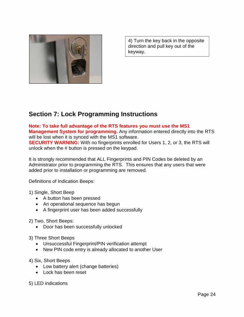
4) Turn the key back in the opposite direction and pull key out of the keyway.

Page 25
Green LED – Indicates any successful fingerprint/PIN verification attempt 6) Illuminating the RTS Exterior Unit Keypad
Press and Hold any of the numbers on the keypad (0 thru 9) for two to three seconds
Keypad will illuminate for 5 seconds
7.1 Menu Buttons 1) The M button stands for Menu and is used to enter menu options and to save changes made to the RTS.
2) The up and down arrows are used to scroll thru menu options.
3) The E button stands for Exit and is used to exit individual menu options. Exception: When setting the date ranges for Access Control, E is used to initiate the “Save” prompt.
M button
UP & DOWN buttons

Page 26
Note: The following instructions assume there are no fingerprints enrolled in the RTS. All setup functions can be done before enrolling an Administrator fingerprint or PIN code. If an Administrator fingerprint is entered before starting the lock setup, fingerprint verification will be required each time the lock is accessed for a program change. It will save time to complete the lock setup before enrolling any Administrator or User FPs and PWDs
7.2 Date/Time Date and Time setting of the RTS is critical when using the MS1 Management Software to ensure accurate time/date stamps for Audit Trail and accurate time/date for Access Control.
E button
Default date, time, and day of the week. Lock ID Battery voltage level
1) Press M, the lock will display in succession: Current Firmware Version

Page 27
No Master! Screen indicates that no fingerprints or User PINs have been programmed into the lock.
2) Option 1 “Lock setup” is highlighted. Press M.
3) Option 1 “Date/Time” is highlighted. Press M.
The Lock Setup menu will then automatically display the Lock Menus: Note: Lock menus 1 through 4 are displayed. Press the Down arrow button to view menus 5-6.
After the Lock Menus are dis-played, if no buttons are pressed for 17 seconds an audible alert (2 beeps) will be heard and then a “Timeout!” message will be dis-played. The lock will then shut down. The setup process can be started again by pressing any of the 4 buttons on the lock front.

Page 28
The time format for the clock is HH:MM:SS (MILITARY or 24 HOUR TIME).
5) Choose the correct month by using the Up/Down arrows.
Press M to save selection.
6) Choose the correct day of the month by using the Up/Down arrows. Press M to save selection.
7) Choose the correct year by using the Up/Down arrows. Press M to save selection.
4) The format for the date setup is MM/DD/YYYY.

Page 29
8) Choose the correct hour by using the Up/Down arrows. Press M to save selection.
9) Choose the correct minute by using the Up/Down arrows. Press M to save selection.
10) Choose the correct second by using the Up/Down arrows. Press M to save selection.
11) Choose the correct day of the week by using the Up/Down arrows. Press M to save selection.

Page 30
7.3 Sensitivity (RTS & RTS-Z) Overview: The lock’s fingerprint levels can be adjusted to meet the desired level of sensitivity. Sensitivity settings range from 1 to 9. Setting 1 is the strictest setting. The quality of fingerprint and placement of the finger or thumb must be almost perfect. Setting 9 is the least stringent setting and is the factory default. This allows a higher margin of error in placement of the finger or thumb on the sensor. Note: If you are having problems with fingerprints being rejected, set the sensitivity level to 9.
12) With the cursor on “SAVE?”, press M to save selection.
13) “SAVED!” indicates TIME / DATE settings have been saved. This will display momentarily and then the setup menu will be shown.
1) In the Lock setup menu, scroll to Option 2 “Sensitivity”. Press M.

Page 31
7.4 Match Mode Overview: “Match Mode” controls how users are able to unlock the lock; using fingerprints, PINs, or a combination of both. There are 3 options available which are outlined below.
2) Use the Up/Down arrows to scroll thru the sensitivity levels until the
desired level is reached. Press M.
3) “SAVED!” indicates the Sensitivity level settings were saved. This will display momentarily and then the setup menu will be shown.
1) In the Lock setup menu, scroll down to “Match Mode” and then press M.

Page 32
Ex. User ID 005 would use the keypad to unlock the lock using this sequence: (5 + # + FP) or (5 + * + PIN + *)
2) 1:N - When this is chosen, all users enrolled at this lock only need to match their enrolled Fingerprint OR PIN Code to unlock the door.
3) 1:1 – When this is chosen, all users enrolled at this lock must enter their User ID and verify their enrolled Fingerprint or PIN Code to unlock the door.
4) 1&N - All enrolled users can use either the 1:1 or 1:N method to unlock the door. This is the factory default setting.
5) Use the Up/Down arrows to scroll thru the matching modes until the desired mode is reached and then press M to save the setting. 4) 1&N - All enrolled users can use either the 1:1 or 1:N method to unlock the door.

Page 33
7.5 Lock ID Overview: Lock ID is used to distinguish between locks for sites with multiple locks installed. By default, all locks are set as 0001. Note: The Lock ID of the RTS is critical when using the MS1 Management Software (for programming and audit trail). The Lock ID in the MS1 MUST correspond with the Lock ID in the MS1 software. If the Lock IDs do not correspond, the lock records may be corrupted.
6) “SAVED!” indicates that the Match Mode settings were saved. This will display momentarily and then the setup menu will be shown.
1) In the Lock Setup menu, scroll down to Option 4 “Lock ID”. Press M.
2) Use the Up/Down arrows to scroll to the desired lock ID. Press M to save setting.

Page 34
7.6 Clear FP&PIN Overview: This menu allows an administrator to delete all fingerprints and PINs from the lock. If Users/Administrators have a PIN code associated with their FP, the PIN codes must be cleared to reset all data. Note: Deleting FPs and PINs for specific users will be explained later in this document.
3) “SAVED!” indicates Lock ID setting was saved. This will display momentarily and then the setup menu will be shown.
1) In the Lock setup menu, scroll down to Option 5 “Clear FP & PIN” Press M.
2) To delete all fingerprints, select Option 1”Clear FP”. Press M.

Page 35
7.7 Access Time Overview: Each lock has 3 different modes of operation which can be active at a given time. The 3 modes are outlined and explained below. There are three TIME MODES that may be chosen for the lock:
3) “Cleared!” indicates that all FPs have been deleted. Note that it will take 3 to 4 seconds for this to display.
5) To delete all PIN Codes, select Option 2 “Clear PIN”. Press M.
4) Wait momentarily for the “Clear FP/Clear PIN” screen to be shown.
6) “Cleared!” will display, indicating that all PIN Codes have been deleted. Note that it will take 3 to 4 seconds for this to display.

Page 36
Note: The Acc-Time Setting chosen/created for the lock will override any specific Timed Access assigned for a specific User set in the “User Edit” menu (see Section 2: User Edit) . For example, if Acc-Time is chosen for the lock and set to Mon, Wed and Fri 9am to 5pm, Users will only have access to unlock the door during the set days and times, no matter what individual timed access was set for them in the User Edit menu. Note: Administrators (User ID 1-3) can always unlock the RTS.
7.7.1 Invalid
3) Acc-Time (Access Time) - This mode allows for timed access to the lock to be created for a specific date range, days of the week and time frame within the days of the week.
2) Anytime - When this is chosen, the lock allows all enrolled Users to unlock the door. The exception to this is if specific Timed Access is set up for individual Users (see Section 2: User Edit).
1) Invalid -This can also be called lock down mode. When this is enabled, only Administrators for the specific lock will have access to unlock the door.

Page 37
Note: Selecting “Invalid” will allow Admin access only.
1) In the Lock setup menu, scroll to Option 6 “Access Time”. Press M.
2) Press the UP arrow once. At the
“Invalid” option, press M.
3) “SAVED!” will be shown momentarily indicating that the lock is now in “Invalid” mode.

Page 38
7.7.2 Anytime
7.7.3 Acc-Time: Note: Administrators (User ID 1-3) can always unlock the RTS. If this option is chosen, “Date, Time, and Week Days” must all be completed for this function.
1) Scroll to Option 2 “Anytime”. Press M.
2) “SAVED!” will be shown momentarily indicating that the lock is now in “Anytime” mode.
1) Scroll to option 3 “Acc-Time”. Press M.

Page 39
4) Use the up and down arrows to choose the appropriate MM, DD and YYYY in each section. When desired value is chosen for each section, press M to move on to the next date value. Example: The desired “From” date is January 01, 2014.
2) Highlight “Date”. Press M.
3) The “From” and “To” Date Range options will be displayed. The format for the Date Range settings is MM/DD/YYYY. Press M.
In the “From” section, use the up/down arrows to select Jan. Press M. Use the up and down arrows to enter “01” (for 1st day of the month). Press M. Use the up and down arrows to enter “2014” (for the Year). Press M.
5) After setting the “To” Year field, press E. “SAVE?” will display on the LCD.

Page 40
Use the same steps as above for the “To” date.
8) With the cursor on the “From” hour, use the Up/Down arrows until desired hour is shown. Press M to save selection. Repeat for the “From” minute setting.
6) Press M to Save Or Press E to exit without saving.
7) Scroll to “Time” and press M. The current setting for “From” and “To” are shown. Press M again.
9) With the cursor on the “To” hour, use the Up/Down arrows until desired hour is shown. Press M to save selection. Repeat for the “To” minute setting.

Page 41
10) After the desired Time Frame has been selected, press M. Message “SAVED?” will display on the LCD.
11) Press M to Save Or Press E to exit without saving.
Page 42
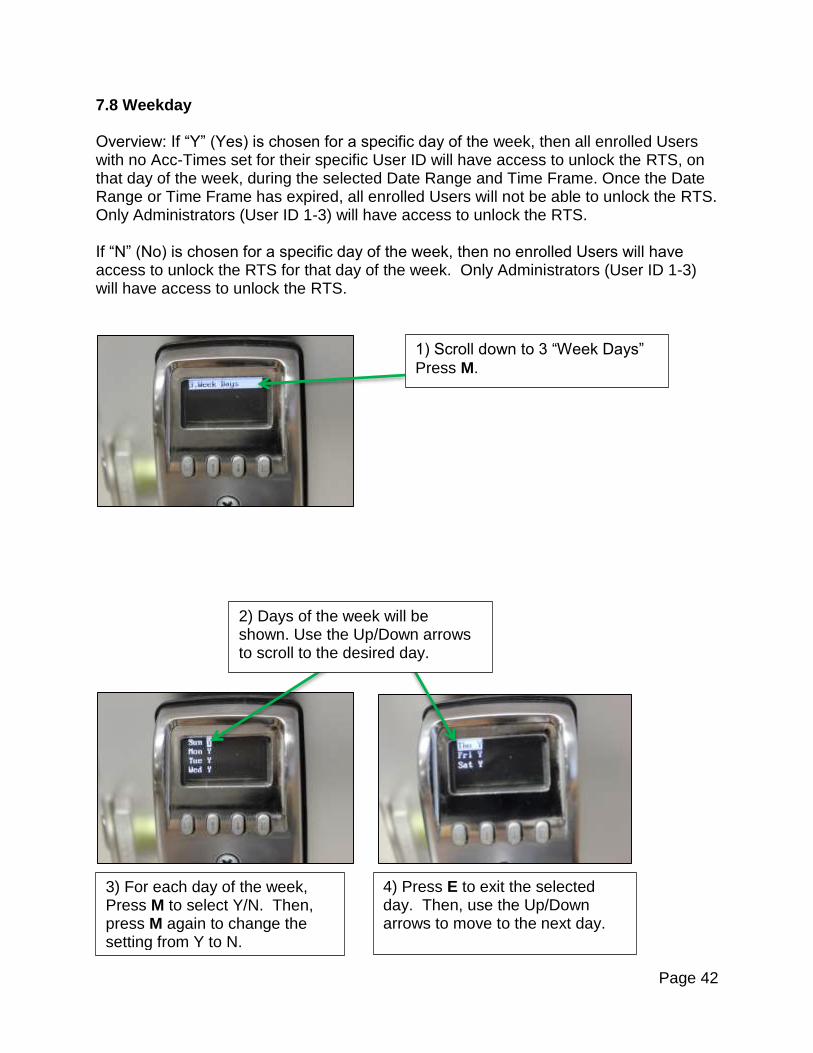
7.8 Weekday Overview: If “Y” (Yes) is chosen for a specific day of the week, then all enrolled Users with no Acc-Times set for their specific User ID will have access to unlock the RTS, on that day of the week, during the selected Date Range and Time Frame. Once the Date Range or Time Frame has expired, all enrolled Users will not be able to unlock the RTS. Only Administrators (User ID 1-3) will have access to unlock the RTS. If “N” (No) is chosen for a specific day of the week, then no enrolled Users will have access to unlock the RTS for that day of the week. Only Administrators (User ID 1-3) will have access to unlock the RTS.
1) Scroll down to 3 “Week Days”
Press M.
2) Days of the week will be shown. Use the Up/Down arrows to scroll to the desired day.
3) For each day of the week, Press M to select Y/N. Then, press M again to change the setting from Y to N.
4) Press E to exit the selected day. Then, use the Up/Down arrows to move to the next day.
Page 43
7.9 Timed TUM Temporary Unlock Mode (TUM): Timed (or Automatic) TUM allows an Administrator to set the RTS to unlock automatically at preset days and times upon the confirmation of a registered user (see FUA below) and then automatically revert to locked (or normal) mode at time expiry. The Administrator may also preset holiday dates so that TUM will not be armed or active on those days. Example: If TUM has been set to operate Monday to Friday from 09:00 to 17:00 (9AM to 5PM) and a preset holiday falls on a Tuesday, the TUM feature will not activate on Tuesday even if a registered User accesses the lock. First User Authentication (FUA): The Administrator will arm the open time and the LCD will show “Armed!” once set. However, TUM will only activate and unlock the door upon the verification of a registered User’s FP or PIN. Door will remain unlocked until preset time expiry. The TUM feature is especially useful for doors that require frequent access (e.g. a shop front during business hours).
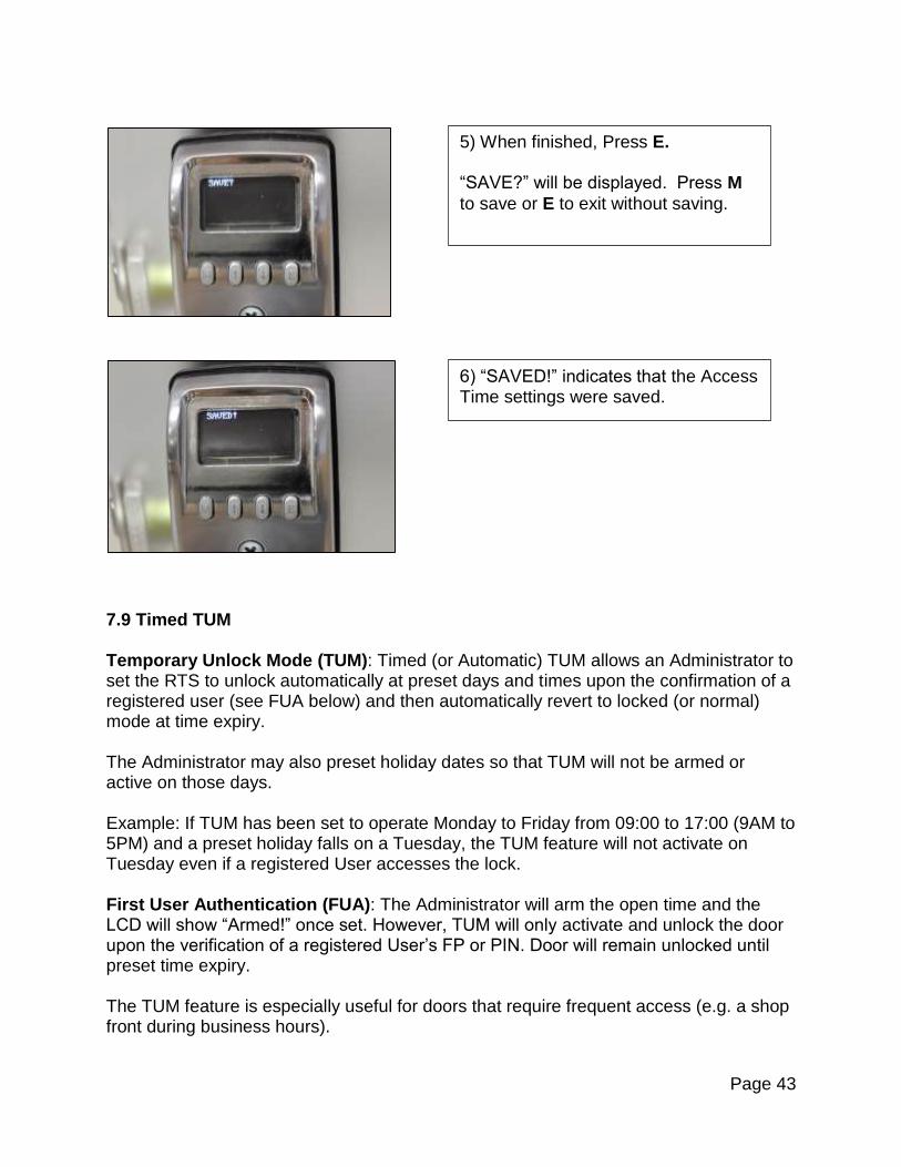
5) When finished, Press E. “SAVE?” will be displayed. Press M
to save or E to exit without saving.
6) “SAVED!” indicates that the Access Time settings were saved.

Page 44
7.9.1 Timed TUM - Setup Menu
7.9.2 Cancel TUM The Cancel TUM function will void all previous preset data. Note: Holiday data will NOT be reset.
1) In the Lock setup menu, scroll down to Option 7 “Timed TUM”. Press M.
2) Press M again to select “Setup”.
Press M to reset ALL data fields. All TUM data fields are reset to dashes in both the “ALL” and “Daily” sub menus as shown below.

Page 45
Tip: There are 2 ways to cancel TUM. The above method will void ALL data fields in the TUM menu and is recommended for a complete reset. Individual day resets may be carried out in their respective sub menu and are detailed in the relevant sections below.
7.9.3 Setup Days Most businesses will operate the Timed TUM mode during business days (e.g. Monday to Friday, 08:00 to 17:00 and Saturday from 09:00 to 12:00). To create TUM settings for this type operation, it is recommended to set TUM times in the “ALL” (days) menu and then edit individual days in which TUM should not be armed. Please read the Important Tips below before setting the time fields.
On initial setup, the system will display “dashes” (-- : --) in all fields
Pressing M will highlight the first “- -” field. Using the Up/Down arrow keys will
insert your desired time.
Pressing M will highlight the next “- -”. Use the Up/Down arrow keys to enter a
time. Repeat this procedure for the remaining fields. If a time is not inserted and
M is pressed again, ALL data fields will revert to “- -”. You will be prompted to save
this entry and start again. This is an intentional design and is the second way to cancel/void TUM for a particular day.
Once all time fields have been entered, pressing M when the “ARM?” icon has been highlighted will change the text to “ARMED!” and the system will automatically return to the previous menu. Do not go back to the previous menu unless you intend to change a data field. If you go back into the previous menu, the “ARM?” prompt will appear again. Press E to exit and all previous data will be retained.
“Thank you!” is shown momentarily indicating that all TUM settings have been deleted.

Page 46
If you press M, the first data field will revert to“- -” To exit this menu with no changes
to the data, press E. All data will be retained.
If M is pressed again, ALL data fields will revert to“- -”. You will be prompted to
“SAVE” this entry and required to start again. This is an intentional design.
Note: If a registered user uses their FP or PIN while in Timed TUM, the RTS will re-enter a locked state. Simply re-enter FP or PIN to regain Timed TUM status.
7.9.3.1 Example – Setup Days Example 1. Lock will be programmed for TUM mode on ALL days from 08:00 to 17:00 except Sunday. We will program ALL days at once and then program Sunday as a separate day.
1) In the Lock Setup menu scroll down to Option 7 “Timed TUM”. Press M.
2) Scroll to Option 1 “Setup”. Press M.
3) Scroll to Option 2 “Setup Days”. Press M.
4) Press M to select 1 “ALL”.

Page 47
Timed TUM is now armed and ready for the first registered User to activate on or after 08:00 on any day of the week. The Lock should now be displaying the “Setup Days” screen as shown below.
6) Use Up/Down arrow keys to insert desired time, press M after each field. Complete all fields in the “Fr :” and “To” sections.
5) Press M to highlight the first data field.
7) Press M when “ARM?” is high-lighted. This will activate TUM.
8) Use the Up/Down arrow keys to navigate to “Sunday”. Press M.
9) Display will show “ARM?”. Press M.

Page 48
The lock is now armed for TUM operation. Tip: As soon as an individual day has been “ARMED!”, the data fields in the “Sunday” menu will revert to “- -” (if set) to indicate that the data is no longer valid.
7.9.4 View TUM Settings
10) The first data field will change to “- -”.
1) To confirm the selections, press E to return to the “Timed TUM” main menu, select 2 “View” by pressing M.
11) Press M again to clear all fields.
12) After all fields are blank and “ARM?” is shown, Press M to save the changes.

Page 49
Note: The alternative method is to edit each individual day. However, that can be time consuming and the above method is recommended.
7.9.5 Setup Holidays
Overview: This menu has been designed for use in conjunction with the Timed TUM mode. Setting dates in this menu that coincides with public holidays, alleviates the need to cancel TUM manually prior to each holiday event. When a date has been set in this menu, Timed TUM will not be armed and therefore will not activate, even with recognition of a registered User.
Twelve Holiday events may be entered into the system.
The menu may be setup for the holiday to occur every year (e.g. Dec 25) or a “one off holiday” for a particular year. Holidays set in this mode will repeat until 2099.
The “Cancel TUM” command in the main menu will not cancel holiday dates, they must be deleted individually.
Please read the Important Tips below prior to setting the time fields.
On initial setup, the system will display dashes (-- : --) in all fields
Pressing M will highlight the first “- -” field. Using the Up/Down arrow keys will
insert your desired time
Pressing M to the next field will highlight the next “- -”. Use the Up/Down arrow
keys to enter a time. Repeat this for all the remaining fields. If a time is not
inserted and M is pressed again, ALL data fields will revert to “- -”. You will then
be prompted to “SAVE” this entry and required to start again. This is an intentional design and is the second way to cancel/void TUM for a particular day.
2) Select 1 “View Days” by pressing M. You can now scroll through each day using the Up/Down arrow keys.
Page 50
Once all time fields have been entered, pressing M when the “ARM?” icon has been highlighted will change the text to “ARMED!” and the system will automatically return to the previous menu. Do not go back into the previous menu unless you intend to change a data field. If you go back into the previous menu, the “ARM?” prompt will appear again. Press E to exit and all previous data will be retained.
If you press M, the first data field will revert to “- -”. To exit this menu with no changes to the data, press E. All data will be retained.
If M is pressed again, ALL data fields will revert to “- -”. You will be prompted to “SAVE” this entry and required to start again. This is an intentional design.
Note: if a registered user uses their FP or PIN while in Timed TUM, the RTS will re-enter a locked state. Simply re-enter FP or PIN to regain Timed TUM status.
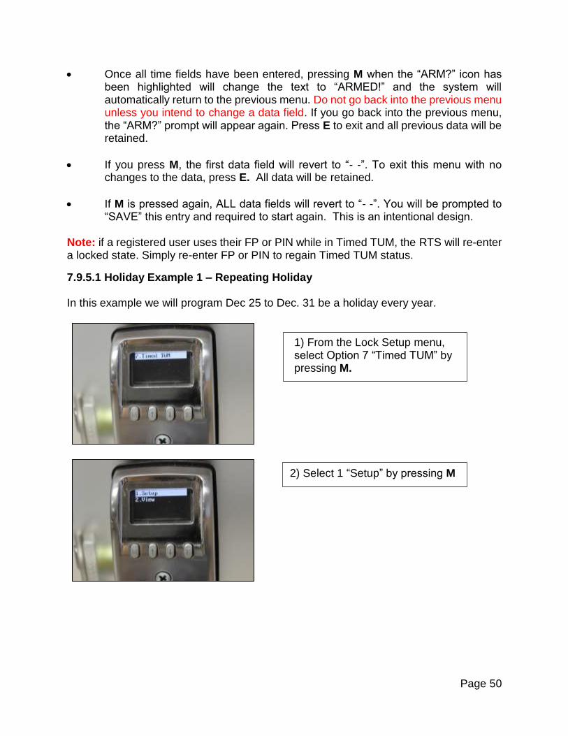
7.9.5.1 Holiday Example 1 – Repeating Holiday In this example we will program Dec 25 to Dec. 31 be a holiday every year.
1) From the Lock Setup menu, select Option 7 “Timed TUM” by pressing M.
2) Select 1 “Setup” by pressing M

Page 51
5) Use the Down Arrow key to
highlight “Every Year”.
Press M.
6) Use the Down Arrow key to
highlight “Dec”.
Press M.
3) Scroll to Option 3 “Setup Holidays”. Press M.
4) Holiday #01 will be shown. Press M to highlight the “Year” field.

Page 52
Note: After “SAVED!” is displayed, do not re-enter the menu unless you need to make corrections. Doing so may delete data.
7.9.5.2 Holiday Example 2 – Non-repeating Holiday In this example we program Dec. 25 to Dec. 31 as a non-repeating holiday.
7) Continue to enter the Month / Day as previously described until prompted to “SAVE?” Note that Dec. 25 is entered both as the beginning and end date.
8) Press M again and the system will momentarily display “SAVED!” It will then revert to “SAVE?”
1) After Holiday #1 setup, “#1” is highlighted. Use Down Arrow key to highlight #2.
Press M.
2) Use the Up/Down Arrow keys to scroll until 2014 is highlighted.
Press M.
9) Press E to exit.

Page 53
7.9.5.3 Holiday Example 3 – Deleting a Holiday
Example: In this example we will delete Dec. 25 to Dec. 31.
1) From the Setup Holiday Menu Use Down Arrow key to navigate to position #2.
3) Press M again. All fields will change to “- - - -”.
3) Enter the month and day fields. When the “SAVE?” prompt is displayed, press M to store the data. “Saved” will be momentarily displayed before the display reverts to “SAVE?”.
2) Press M: “Year” field will change to “- - - -”.
Page 54
7.9.5.4 View Holidays
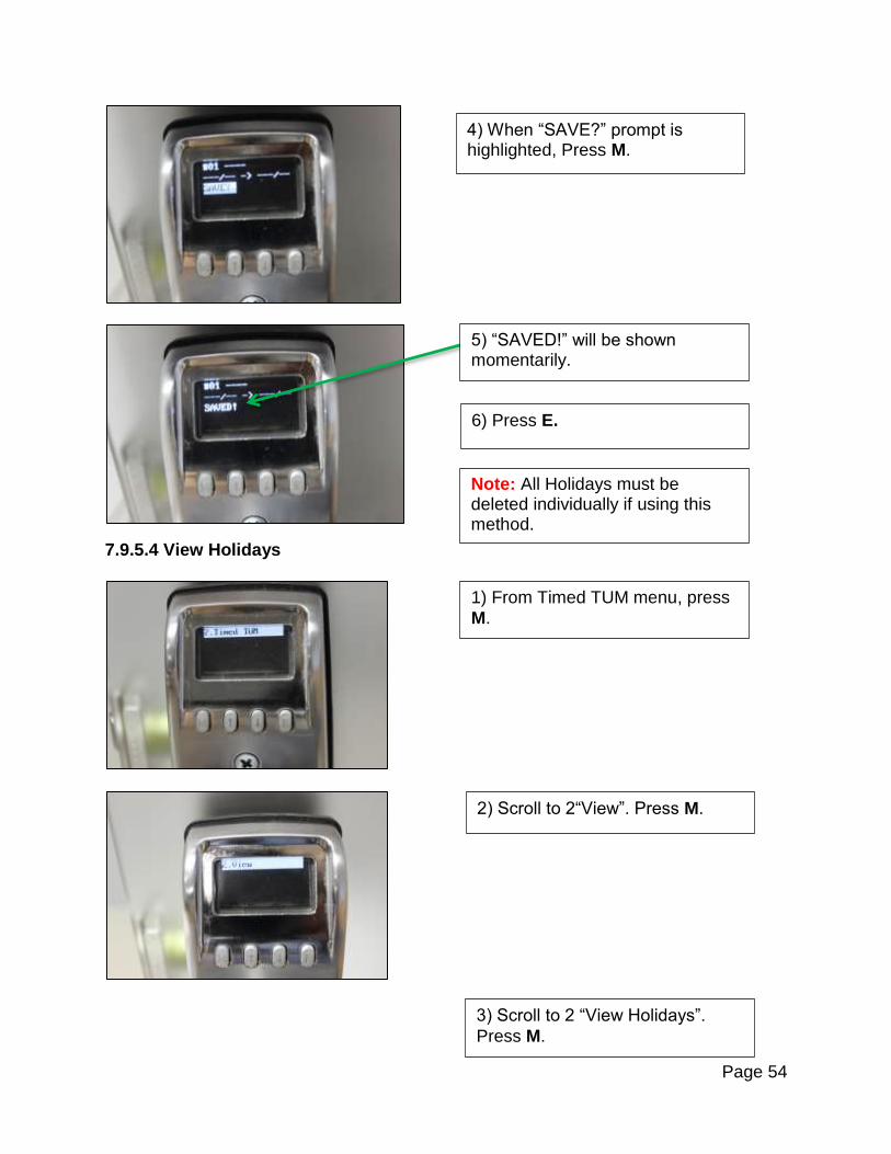
4) When “SAVE?” prompt is highlighted, Press M.
6) Press E.
1) From Timed TUM menu, press
M.
2) Scroll to 2“View”. Press M.
Note: All Holidays must be deleted individually if using this method.
3) Scroll to 2 “View Holidays”.
Press M.
5) “SAVED!” will be shown momentarily.
Page 55
7.9.6 Update via USB
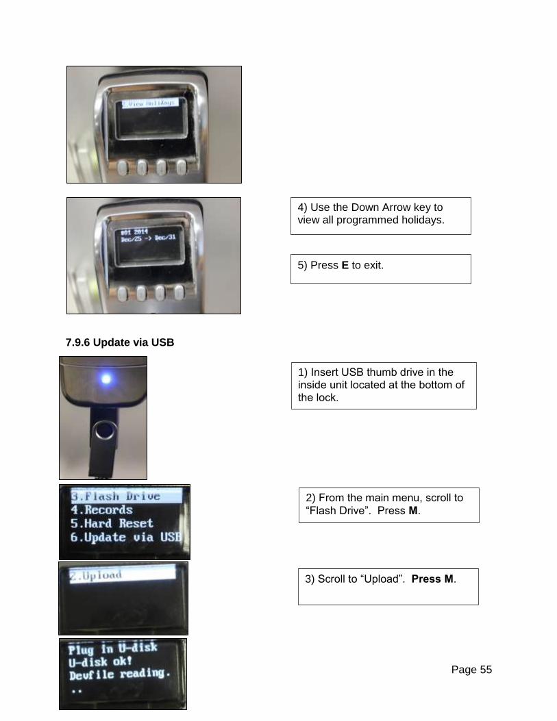
4) Use the Down Arrow key to view all programmed holidays.
5) Press E to exit.
1) Insert USB thumb drive in the inside unit located at the bottom of the lock.
2) From the main menu, scroll to
“Flash Drive”. Press M.
3) Scroll to “Upload”. Press M.
Page 56
Section 8: Authorization Management Overview: User IDs 1-3 are “Administrators.” They have complete access to program the RTS and to unlock the door at any time. User IDs 4-7 are “Managers.” They have limited access to program the RTS. Managers can delete User IDs, edit the Timed TUM menu, and unlock the door at any time User IDs 8-999 are “General Users.” They have access to unlock the door at times set up by one of the Administrators. General Users and have no programming rights on the RTS. For RTS and RTS-Z After an administrator fingerprint has been enrolled, it must be verified by the lock before the menu options can be accessed. The term “fingerprint” is used as a general term to describe fingers or thumbs used for enrollment/verification. Also, the term “finger” can refer to a finger or thumb. Before enrolling and verifying fingerprints, please read the following helpful hints for Fingerprint Enrollment and Verification: Tips on Enrolling Fingerprints (RTS and RTS-Z)
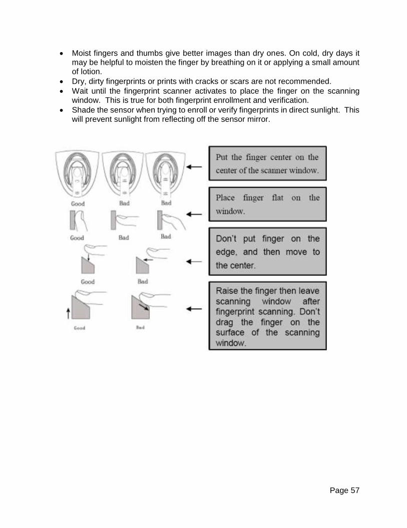
The center of the vortex (swirl) of the fingerprint pattern is the key data point. It should be placed in the center of the sensor’s glass window in a consistent way. The fingerprint should be well defined with the peaks and valleys of the vortex ridge pattern clearly visible.
Light pressure when placing the finger or thumb on the scanner gives the best image. The finger should be held flat and must not move during scanning.
Adjust Fingerprint Sensitivity settings per Section 5.3
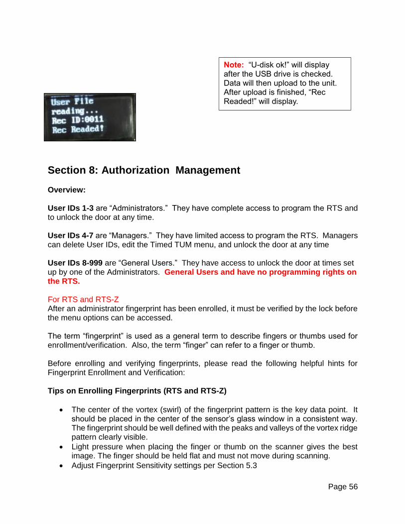
Note: “U-disk ok!” will display after the USB drive is checked. Data will then upload to the unit. After upload is finished, “Rec Readed!” will display.
Page 57
Moist fingers and thumbs give better images than dry ones. On cold, dry days it may be helpful to moisten the finger by breathing on it or applying a small amount of lotion.
Dry, dirty fingerprints or prints with cracks or scars are not recommended.
Wait until the fingerprint scanner activates to place the finger on the scanning window. This is true for both fingerprint enrollment and verification.
Shade the sensor when trying to enroll or verify fingerprints in direct sunlight. This will prevent sunlight from reflecting off the sensor mirror.

Page 58
8.1 Enrolling Fingerprints (RTS and RTS-Z) In this example we will add fingerprints for User 1 (Admin 1).
The lock will then display:
Date/time
Lock ID
Battery voltage
1) Press M. The lock will momentarily display a welcome message with the current Firmware version number.
2) Scroll down to Option 2 “User edit”. Press M.
“NO MASTER!” will momentarily be displayed followed by Lock menu options 1 through 4.

Page 59
Note: Since no fingerprints have been enrolled for this User ID; 1N, 2N, 3N will be displayed. A total of 3 fingerprints may be enrolled for each User ID.
After pressing “#” key, the following screen will be displayed: Note that ID:1 is now being displayed.
3) When “ID:” is displayed, enter a numerical value and then press “#”. Note: Selection must be made within 5 seconds.
4) When “Add FP” is highlighted, press M.
5) “Add FP” is displayed along with “1N2N3N”. “1N” is highlighted. Place finger on the sensor. Press M.

Page 60
If the scan attempt was unsuccessful, “Failed” will display on the LCD and 1N will not change to 1Y. Repeat the steps above to try again. Note: The same finger can be used for fingers 2 and 3. This is recommended for Users with poor quality fingerprints. Usually, different fingers will be used for fingers 1, 2 and 3.
“Capturing…” will be shown while the FP is being scanned.
7) If finger 1 was successfully enrolled, a single short beep will be heard, the LCD will display “Success,” and “1N” will change to “1Y.”
8) Rest finger on sensor. Press the Up Arrow to highlight “2N.” Press M.
6) The sensor will flash 3 times. Keep finger on the sensor while it flashes.

Page 61
If unsuccessful, “Failed” will display on the LCD and 2N will not change to 2Y. Repeat the steps above to try again.
2N changed to 2Y indicates a successful scan.
When 3 fingerprint matches for a user have been successfully enrolled, “1Y2Y3Y” will be displayed.
“Capturing…” will be shown while the FP is being scanned.
“Capturing…” will be shown while the FP is being scanned.
9) Rest finger on sensor. Press the Up Arrow to highlight “3N.” Press M.

Page 62
If unsuccessful, “Failed” will display on the LCD and 3N will not change to 3Y. Repeat the steps above to try again.
8.2. Add or modify a User PIN Overview: When this option is chosen, a PIN Code can be created, changed, or deleted for a specific User ID. In the example below we will create User ID 1 and add a 4 digit PIN.
2) Using front keypad: press 1 #.
Enter the PIN followed by “#”.
1) Scroll to the “User Edit” menu. Press M.
When “PIN:” is displayed, use the front keypad to enter a unique code (from 1 to 10 digits) and then press #.

Page 63
Tip: If you enter a digit in error, use “*” to delete the last entered digit.
8.3 Deleting Fingerprints and PINs Overview: When this option is chosen, the fingerprints and/or PINs associated with the specific User ID will be deleted. In this example, we will delete all FPs and PIN for user ID 50.
1) Scroll to the “User Edit” menu. Press M.
2) Using front keypad press 5 0 #.
LCD screen will display “SAVED!”.

Page 64
“Deleted!” indicates all FPs and PIN for user 50 were deleted.
Option 1 (FP Only) and Option 2 (PIN Only) operate in the same manner as Option 3.
This menu will be displayed. It allows deletion of “PIN Only”, “FP Only”, or both “FP&PIN”.
3) Select option 3. Press M.
Page 65
8.4 Access Time Overview: Choosing this option allows timed access to be created for a specific date range, days of the week or time frame within the days of the week for a User ID. Each USER ID has three TIME MODES that can be created for them.
1. Invalid - This can also be called “lock down” mode. When this is enabled, the User will not be able to unlock the door with fingerprints or PIN Codes until an Administrator re-assigns them to Any Time or Acc-Time.
2. Any Time - When this is chosen, the User can unlock the door with fingerprints or PIN Codes at any time. The exception to this is if specific Timed Access is set up for the LOCK (Menu 1; Lock Setup: 1.6. Access Time).
3. Acc-Time – When this is chosen, the User can unlock the RTS with fingerprints
or PIN Codes during a specific date range, days of the week or time frame within the days of the week. Acc-Time means Access Time.
Note: The Time Setting chosen or created for the LOCK (Menu 1, Lock Setup: 1.6. Access Time) will override any Timed Access assigned for a User. Example: If Acc-Time for the lock is set to Mon, Wed and Fri 9am to 5pm, Users will only have access to unlock the door during those times, no matter what individual timed access was set for them. Administrators (User ID 1-3) will always have access to unlock the RTS. Tip: To delete the last entered digit on the outside keypad, press “*”.

Page 66
8.4.1 Example – Access Time for a specific User ID
8.4.1.1 Invalid This setting will disable all access for the User ID until an Administrator resets it to Anytime or Acc-Time.
From the User edit menu, select
the User ID. Press #.
Scroll to 1 “Invalid”. Press M.
Display will momentarily show “SAVED!” and then return to User Access Time menu.
Scroll to 4 “Access Time”.
Press M.

Page 67
8.4.1.2 Anytime
8.4.1.3 Acc-Time
8.4.1.3.1 Date
Scroll to 2 “Anytime”. Press M.
1) Scroll to 3 “Acc-Time”. Press M.
Display will momentarily show “SAVED!” and then return to User Access Time menu.

Page 68
2) Highlight “Date” Press M.
4) Use the Up/Down arrow keys to choose the DD & YYYY. When desired value is chosen for each section, press M to move to the next value.
5) Once the Date Range is entered, press E. “SAVE?” will display on the LCD. Press M to save. Press E to exit without saving.
3) Press M. The “Fr” month field will be highlighted. Use the Up/Down arrow keys to select the month.
“From” and “To” Date Range options will be displayed. Date Ranges are in MM/DD/YYYY format.

Page 69
8.4.1.3.2 Time Use the following steps to set up the Time for the User ID.
“SAVED!” indicates that the date range setup was saved.
1) Scroll to 2 “Time” Press M.
2) The “Fr” hour field will be highlighted. Press M.
5) Once the Time Frame is set up, press E. “SAVE?” will display on the LCD. Press M to save. Press E to exit without saving.
3) Use the Up/Down arrow keys to select the desired hour. Press M.

Page 70
8.4.1.3.3 Days of the Week Overview: This is an extension to the Date Range or Time Frame options. If “Y” (Yes) is chosen for a specific day of the week, then the user can only unlock the RTS on that day of the week, during the Date Range and Time Frame that has already been created. If “N” (No) is chosen for a specific day of the week, then the user will not be able unlock the RTS for that day of the week.
2) Press M to select Y/N. Press M again to toggle between “Y” (Yes) and “N” (No) for each day of the week.
1). Scroll to 3“Week Days”.
Press M.
“SAVED!” will be shown indicating that the Time frame setup was saved successfully.

Page 71
Section 9: Z-Wave functionality (RTS-Z & RTS-PZ)
9.1. Alarm/Notification functionality
When Door is locked or unlocked by the controller or user, the device notifies to the controller by using Notification.
9.2. Compatibility
This product can be included and operated in any Z-Wave network with other Z-Wave certified devices from other manufacturers and/or other applications. All non-battery operated nodes within the network will act as repeaters regardless of vendor to increase reliability of the network.
9.3. Association Group
Grouping identifier is 1 and maximum number of devices that can be added to the group is 5.
3) When completed, press E. “SAVE?” will display on the LCD. Press M to save. Press E to exit without saving.
“SAVED!” indicates Day of the week settings were saved.

Page 72
When the battery of the device is lower than a specific threshold the door will still lock or unlock or the device can be reset. It will notify the controller that the operation was completed and of the low battery condition. The lifeline group contains Battery, DoorLock, Notification and Device Reset Locally messages.
9.4. Controller Compatibility
The device is Z-Wave security enabled and a Z-Wave Security enabled controller is required to fully utilize the device.
Section 10: External Applications There are 3 separate external items that can be wired up to the Locks
1. Auxiliary 6 Volt Power Supply: red and black wires 2. Normally Open Items: blue and white wires 3. RS485 Switches: yellow, brown and black wires
10.1. Auxiliary Power Connection
Red and black wires with inline connector
This is the optional DC power connection
If this option is not used disconnect the “pigtail”
If used you may provide 6 to 12vdc (red + black -)
The red and black wires have a connector that can be detached and wired to a 6V power supply. Disconnect the wires and hard wire to the 6V source. Once hard wired reconnect to the lock.
Page 73
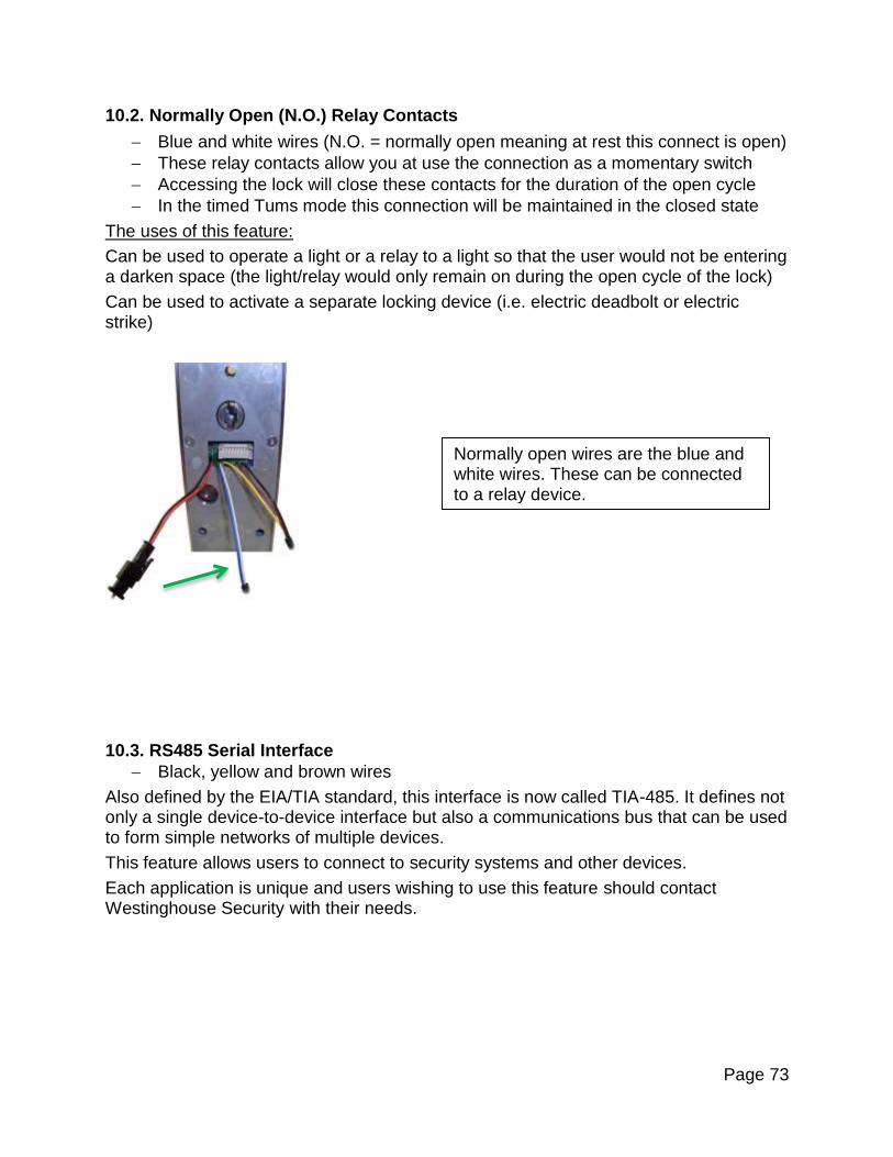
10.2. Normally Open (N.O.) Relay Contacts
Blue and white wires (N.O. = normally open meaning at rest this connect is open)
These relay contacts allow you at use the connection as a momentary switch
Accessing the lock will close these contacts for the duration of the open cycle
In the timed Tums mode this connection will be maintained in the closed state
The uses of this feature:
Can be used to operate a light or a relay to a light so that the user would not be entering a darken space (the light/relay would only remain on during the open cycle of the lock)
Can be used to activate a separate locking device (i.e. electric deadbolt or electric strike)
10.3. RS485 Serial Interface
Black, yellow and brown wires
Also defined by the EIA/TIA standard, this interface is now called TIA-485. It defines not only a single device-to-device interface but also a communications bus that can be used to form simple networks of multiple devices.
This feature allows users to connect to security systems and other devices.
Each application is unique and users wishing to use this feature should contact Westinghouse Security with their needs.
Normally open wires are the blue and white wires. These can be connected to a relay device.

Page 74
Section 11: Support Information Contact your RTS distributor or contact us at or 800-916-3985 for additional support.
All RMA, Warranty, and Repair requests must be submitted from the Support page at
www.westinghousesecurity.com. Trouble Tickets for technical support may also be
submitted by visiting the Support page.
Limited Warranty
Westinghouse Security warrants the product against defects in material and
workmanship for a period of two years from the date of original purchase. This warranty
is in lieu of all other express warranties. During the warranty period, Westinghouse
Security agrees to repair or, at its option, replace the defective product, or any part of it
without charge for parts or labor. This is your exclusive remedy. This warranty does not
cover damage resulting from accident, misuse, abuse, improper installation or
operation, lack of reasonable care, the affixing of any attachment not provided by with
the product and loss of parts. The warranty is voided in the event any unauthorized
person alters or repairs the unit.
DISCLAIMS ANY IMPLIED WARRANTY, INCLUDING THE WARRANTY OF
MERCHANTABILITY AND THE WARRANTY OF FITNESS FOR A PARTICULAR
PURPOSE, AS OF THE DATE TWO YEARS FROM THE ORIGINAL PURCHASE OF
THE PRODUCT. WESTINGHOUSE SECURITY ASSUMES NO RESPONSIBILITY
FOR ANY SPECIAL, INCIDENTAL OR CONSEQUENTIAL DAMAGES.
The yellow, brown and black wires are for RS485 serial communication devices.

Page 75
THIS WARRANTY GIVES YOU SPECIFIC LEGAL RIGHTS, AND YOU MAY HAVE
OTHER RIGHTS WHICH VARY FROM STATE TO STATE. SOME STATES DO NOT
ALLOW THE EXCLUSION OR LIMITATION OF SPECIAL, INCIDENTAL OR
CONSEQUENTIAL DAMAGES OR LIMITATIONS ON HOW LONG AN IMPLIED
WARRANTY LASTS, SO THE ABOVE EXCLUSION AND LIMITATION MAY NOT
APPLY TO YOU.

Page 76
Appendix A – User Enrollment Table
User ID
Hand (L/R)
Finger
PIN
Name