westinghouse non-proprietary class 3 · evidence report for high level waste ukp-gw-gl-056,...
TRANSCRIPT


Westinghouse Non-Proprietary Class 3
Westinghouse Electric Company LLC
1000 Westinghouse Drive Cranberry Township, PA 16066
Copyright © 2011 Westinghouse Electric Company LLC
All Rights Reserved
UK AP1000 Radioactive Waste Management Case Evidence Report for High Level Waste
UKP-GW-GL-056, Revision 2
UK AP1000 RWMC Revision History Evidence Report for HLW
UKP-GW-GL-056 ii Revision 2
REVISION HISTORY
Revision Description of Change
0 Initial Submittal
1 Complete rewrite. Revised in-line with current Guidance (February 2010) and comments from ROA-AP1000-34.A5 (31 August 2010).
2 Revised in-line with new Long Term Storage of Waste document UKP-GW-GL-085.
Addresses new Westinghouse trademark guidelines.
Trademark Notices
AP1000 and ZIRLO are trademarks or registered trademarks in the United States of Westinghouse Electric Company LLC, its subsidiaries and/or its affiliates. These marks may be used and/or registered in other countries throughout the world. All rights reserved. Unauthorized use is strictly prohibited. Other names may be trademarks of their respective owners.

UK AP1000 RWMC Table of Contents Evidence Report for HLW
UKP-GW-GL-056 iii Revision 2
TABLE OF CONTENTS
Section Title Page
REVISION HISTORY ................................................................................................................................. ii
LIST OF FIGURES .................................................................................................................................... vii
1. EXECUTIVE SUMMARY ............................................................................................................. 1
2. OBJECTIVE AND SCOPE ............................................................................................................. 2
3. RELEVANT WASTES ................................................................................................................... 3
4. BACKGROUND ............................................................................................................................. 4
4.1 Applicable Legislation ........................................................................................................ 4
4.2 Radioactive Waste Management Case ................................................................................ 5
5. GENERAL REQUIREMENTS ..................................................................................................... 12
5.1 Waste Streams .................................................................................................................. 12
5.2 Current Ownership of the Waste Streams ......................................................................... 12
5.3 Management Strategy for the Waste Streams ................................................................... 12
5.4 Proposed Waste Management Processes .......................................................................... 13
5.5 Relevant Buildings and Plant ............................................................................................ 14
5.6 Facility, Organisation, and Management of Radioactive Waste ....................................... 14
5.7 Interdependencies Among Steps in Generation and Management of Radioactive Waste Management .......................................................................................................... 15
5.8 How the Generation of Radioactive Waste is Minimised ................................................. 16
5.9 How Radioactive Waste Is Adequately Controlled and Contained .................................. 16
5.10 How Safeguards and Security Issues Will Be Addressed ................................................. 17
5.11 How Radioactive Waste Meets Relevant Requirements to Enable Its Transport ............. 17
5.12 Quality Assurance Arrangements ..................................................................................... 18
5.13 Information and Records Management Arrangements ..................................................... 18
6. RADIOACTIVE WASTE MANAGEMENT STRATEGY .......................................................... 21
6.1 Subsidiary or Secondary Waste Streams Produced .......................................................... 21

UK AP1000 RWMC Table of Contents Evidence Report for HLW
UKP-GW-GL-056 iv Revision 2
6.2 Identification of Ultimate Destinations for the Wastes Be It Disposal or Long-term Storage .............................................................................................................................. 21
6.3 Options and Processes Considered to Convert Raw Waste into a Product Suitable for Long-term Storage ...................................................................................................... 21
6.4 Reasons and Assumptions Used to Reject Options .......................................................... 21
6.5 Reasons, Assumptions, Uncertainties, Calculations, and Conclusions for Selecting Preferred Option(s) ........................................................................................................... 21
6.6 How Preferred Option Is Consistent with the Integrated Waste Strategy ......................... 22
6.7 How Preferred Option Is Consistent with Existing and Reasonably Foreseeable Provisions for Transport, Storage, and Disposal .............................................................. 22
6.8 Details of Stakeholder or Public Consultation .................................................................. 22
6.9 Use of and Implications for Existing Waste Disposal Routes If Preferred Option Is Selected ............................................................................................................................. 23
7. WASTE MINIMISATION, CHARACTERISATION, AND SEGREGATION .......................... 24
7.1 Description of Techniques Adopted to Prevent or Minimise Arisings ............................. 24
7.2 Details of Methods to Be Used for Segregation and Characterisation of Wastes and Practicable Steps Taken to Avoid Dilution ....................................................................... 24
7.3 Evidence That Waste Streams Can Be Characterised to Level Necessary to Ensure Compliance with Specification for Waste Packaging ....................................................... 25
8. CONDITIONING AND DISPOSABILITY .................................................................................. 26
8.1 How Passive Safety Will Be Achieved ............................................................................. 26
8.2 Evidence That Waste Package Produced Will Be Consistent with Existing and Reasonably Foreseeable Provisions for Transport, Storage, and Disposal ....................... 26
8.3 Identification of any Significant Issues That May Challenge Disposability .................... 27
8.4 Intended Specification for Waste Package ....................................................................... 27
8.5 How Inventory of Individual Packages Will Be Controlled and Measured ..................... 27
8.6 Demonstration That Proposed Packaging and Conditioning Strategy Uses BPM/BAT to Minimise the Long-term Environmental Impact and Ensure Associated Doses Are ALARP ......................................................................................... 27
8.7 Demonstration That Proposed Strategy Will Not Lead to Significant Increases in the Possibility of a Neutron Chain Reaction in a Disposal Facility .................................. 28
8.8 Assessment of Long-term Performance and Degradation of Waste Containers ............... 28
8.9 Identification of Any Potential Package Failure Mechanisms .......................................... 29

UK AP1000 RWMC Table of Contents Evidence Report for HLW
UKP-GW-GL-056 v Revision 2
8.10 Evaluation of Any Reactions That May Take Place Between the Waste and the Conditioning Matrix ......................................................................................................... 29
8.11 Evaluation of Long-term Performance of Waste Form .................................................... 30
8.12 Assessment of Potential for Gas Generation from Wastes in the Long-term ................... 30
8.13 Consideration of Impact of Toxic Materials as a Result of Release from a Disposal Facility and Environmental Impacts that Might Arise During, or as a Result of, Operations ......................................................................................................................... 30
8.14 An Assessment of the Potential Impact from Any Detrimental Effects Due to Chemical Species That May Be Present in the Wastes or Might Reasonably Be Expected to Form .............................................................................................................. 31
8.15 How Conditioned Waste That Does Not Meet Specifications Will Be Managed ............ 31
8.16 Arrangements for Quality Assurance and Records ........................................................... 32
8.17 How Developments in Disposal Facility Requirements Will Be Taken Into Account ..... 32
9. STORAGE OF RADIOACTIVE WASTE .................................................................................... 33
9.1 Storage Capacity Requirements ........................................................................................ 33
9.2 Package Lifetime and the Proposed Timescale for Storage .............................................. 33
9.3 Demonstration That Conditioned Wastes Will Remain Within Agreed Specification for Final Disposal Throughout the Storage Period ........................................................... 33
9.4 How Passive Safety Will Be Achieved ............................................................................. 34
9.5 Integrity of Storage Arrangements ................................................................................... 34
9.6 Arrangements for Leak Detection ..................................................................................... 34
9.7 Details of Ventilation Requirements and Filtration of Airborne Releases ....................... 35
9.8 Environmental Monitoring Arrangements ........................................................................ 35
9.9 How Stored Waste Will Be Retrieved and Inspected ....................................................... 36
9.10 How Packages That Show Evidence of Deviating from Specification During Storage Will Be Managed ................................................................................................. 36
10. CONTROL, ACCOUNTANCY, AND RECORDS ...................................................................... 38
10.1 Arrangements for Recording Information That May Be Required in Future to Facilitate Subsequent Management of Radioactive Substances and Facilities ................. 38
10.2 Ongoing Measures to Demonstrate Whether Compliance with Requirements and Standards Has Been Achieved .......................................................................................... 38
10.3 Timescales over Which Such Information Shall Be Recorded and Retained ................... 39

UK AP1000 RWMC Table of Contents Evidence Report for HLW
UKP-GW-GL-056 vi Revision 2
10.4 Environmental Conditions for Storage and Long-term Preservation of Records ............. 39
11. FUTURE DEVELOPMENT ......................................................................................................... 41
12. CONCLUSIONS ........................................................................................................................... 43
13. REFERENCES .............................................................................................................................. 44
APPENDIX 1 SUPPORTING INFORMATION CHECKLIST ............................................................... 46
APPENDIX 2 GLOSSARY OF TERMS .................................................................................................. 58
APPENDIX 3 SPENT FUEL DISPOSABILITY PLAN .......................................................................... 61

UK AP1000 RWMC Table of Contents Evidence Report for HLW
UKP-GW-GL-056 vii Revision 2
LIST OF FIGURES
Figure 4-1. AP1000 RWMC Waste Management Document Hierarchy ................................................... 11
Figure 5-1. AP1000 Solid Radwaste Management Strategy ...................................................................... 20
Figure 5-2. Solid HLW Treatment and Disposal ....................................................................................... 20
Figure A3-1. Spent Fuel Disposability Plan .............................................................................................. 62

UK AP1000 RWMC 1. Executive Summary Evidence Report for HLW
UKP-GW-GL-056 1 Revision 2
1. EXECUTIVE SUMMARY
This document has been prepared for the Generic Design Assessment (GDA) 1 of the Westinghouse AP1000 TM Nuclear Power Plant. The generic nature of the current assessment phase means that a specific and detailed radioactive waste management case(s) (RWMCs) cannot yet be fully developed. Therefore, it is a requirement to demonstrate that sufficient detailed information will be available to allow the necessary RWMCs to be developed. Some of the required information is available now; other information will become available as the AP1000 designs, management systems, and operating procedures are further developed to suit a specific site and the associated licensing process. The information contained herein is consistent with the level of detail required at this stage of the GDA process.
This evidence report is presented to demonstrate that suitable RWMCs can be prepared by the site licensee in the future. The evidence takes the form of a series of statements plus references to supporting information. It is important to note that this evidence report is not an RWMC; rather, it is a key to the information required to produce the necessary RWMCs.
RWMCs will be prepared in accordance with the guidance issued by the Health and Safety Executive ( HSE), the Environment Agency (EA), and the Scottish Environment Protection Agency (SEPA) (collectively referred to as “the regulators”) [Ref. 1]. This guidance describes regulatory expectations with respect to the production, content, maintenance, and review of RWMCs, and provides links to further guidance that describe how the components of RWMCs can be produced.
This United Kingdom (UK) AP1000 RWMC evidence report addresses the high level waste (HLW) stream arising from AP1000 operation, maintenance, and eventual decommissioning. The report concludes that there is sufficient information provided through the GDA process to allow licensees to produce a detailed RWMC for HLW during the site licensing stage.
1. Glossary of Terms is found in Appendix 2.

UK AP1000 RWMC 2. Objectives and Scope Evidence Report for HLW
UKP-GW-GL-056 2 Revision 2
2. OBJECTIVE AND SCOPE
The objective and scope of this document is to provide documentary evidence that sufficient information will be available to allow the preparation of UK AP1000 RWMCs for HLW by a specific site licensee. A companion document for intermediate level waste (ILW) has been produced [Ref. 28].
This document also aims to identify the interdependencies between the major documents that will be issued as part of the GDA process to support the RWMC and to identify where additional detail is needed and how this additional detail will be developed (for example, during detailed design).

UK AP1000 RWMC 3. Relevant Wastes Evidence Report for HLW
UKP-GW-GL-056 3 Revision 2
3. RELEVANT WASTES
Within the Regulators joint guidance for RWMCs [Ref. 1], higher activity radioactive waste is defined as: “HLW, ILW and such low level waste (LLW) as cannot be disposed of at present.”
There are no LLW expected to be generated by a future AP1000 that cannot be disposed of at present, therefore, for the AP1000, there are two types of final waste that the RWMCs must address:
Solid ILW comprising spent ion exchange resin, activated carbon, primary circuit filters and ILW arising during decommissioning.
Solid HLW comprising spent fuel.
For the GDA process, two UK AP1000 RWMC evidence reports have been produced. This document addresses the HLW stream. A companion document addresses the ILW stream(s) [Ref. 27].

UK AP1000 RWMC 4. Background Evidence Report for HLW
UKP-GW-GL-056 4 Revision 2
4. BACKGROUND
Westinghouse Electric Company LLC (Westinghouse) is seeking approval to have an AP1000 simplified passive advanced light water reactor electricity generating plant built in the United Kingdom. The UK Nuclear Regulators have developed a GDA process to endorse generic designs, enabling new build licensing to proceed more smoothly. Part of this process is to assess the management of radioactive materials on site and their eventual disposal. Recognised documents used in the industry to demonstrate effective management of radioactive waste are the Integrated Waste Strategy (IWS), Best Available Technique (BAT) studies and Radioactive Waste Management Cases (RWMC).
This document is the RWMC evidence report for HLW, and it has been prepared for the GDA. As explained earlier, this document is a key to information required to produce RWMCs. This information will be used by the operators of AP1000 on a specific site to prepare the necessary RWMC documents. This evidence report has been prepared in line with the UK Government conclusion that ‘in the absence of any proposals from the industry, any new nuclear power stations that might be built in the UK should proceed on the basis that spent fuel will not be reprocessed and that plans for, and financing of, waste management should proceed on this basis’ [Ref. 23]
Guidance has been published from the Regulators on the management of higher activity radioactive waste on nuclear licensed sites [Refs. 1 and 2]. This guidance describes the regulatory expectations with respect to the production, content, maintenance, and review of an RWMC.
AP1000 RWMCs will address the longer term safety and environmental issues associated with a particular waste from generation to conditioning into the form in which it will be suitable for storage and eventual disposal.
Before reaching its final disposal or storage destination, AP1000 radioactive waste will be processed and transferred from the AP1000 to onsite storage facilities. The AP1000 and associated waste handling plants and the storage facility each have a nuclear safety case justifying its safe operation. Certain sections of these safety cases may cover, in whole or in part, the topics of concern to the AP1000 RWMCs.
It should be noted that the term “radioactive waste management case” is used as a construct to explain how information should be organised so that specific site licensee’s can demonstrate the long-term safety and environmental performance of higher activity wastes. Since AP1000 RWMCs form part of the overall safety case and the safety cases associated with storage facilities, they will be treated and managed as safety cases in terms of Licence Conditions 14, 15, and 19–22.
4.1 Applicable Legislation
Facilities and activities for predisposal management of radioactive waste, including decommissioning activities, are subject to safety and environmental impact assessments to demonstrate that they are adequately safe and, more specifically, that they will be in compliance with safety and environmental requirements established by the regulators. The relevant legislation is listed below:
Nuclear Installations Act 1965 (as amended)
Standard license conditions applied to nuclear site licences and, in particular, those pertaining to the management of radioactive waste: Licence Condition (LC) 4, 32, 34

UK AP1000 RWMC 4. Background Evidence Report for HLW
UKP-GW-GL-056 5 Revision 2
and 35. Also, because the RWMC is the safety case for the management of a particular radioactive waste stream (or streams), LCs 14, 15 and 19-23 are also particularly relevant
Health and Safety at Work Act 1974
Environment Act 1995
Radioactive Substances Act 1993
The guidance for the preparation of an RWMC [Ref. 1] also identifies that there may be other short-term environmental issues (such as discharges) that may be covered by separate environmental legislation. It is acknowledged that the RWMC may not be the best place to demonstrate compliance with this separate legislation, and licensees should refer to other environmental legislation to ensure that their radioactive waste management cases are consistent with it.
4.2 Radioactive Waste Management Case
The RWMCs that will be developed for the AP1000 will demonstrate the longer term safety and environmental performance of the planned management of specific wastes from generation to conditioning into the form which will be suitable for storage and eventual disposal. The RWMCs will provide a complete picture of the management of waste streams that cannot necessarily be seen from examination of the individual plant safety cases and environmental documentation. At each stage, the RWMCs will aim to ensure that radioactive waste is managed in a way that protects the health and interests of people and the integrity of the environment, both now and in the future, inspires public confidence and takes account of costs. The long timescales involved may mean that the RWMCs cannot cover all eventualities, and that some aspects may not yet be known. The RWMCs will make it clear how such uncertainties are being dealt with and refer to a programme of work, where appropriate, that is designed to address any gaps in knowledge.
4.2.1 Purpose
RWMCs developed for AP1000 will provide a transparent demonstration of adequate radioactive waste management for the waste stream(s) covered. They will provide support for safe operation by establishing and demonstrating that the plants, processes, activities, modifications, and the like, proposed for managing radioactive wastes:
Comply with regulatory requirements.
Provide for an acceptable outcome in terms of national policy for radioactive waste management.
Are consistent with national and international standards of radioactive waste management.
Take account of interdependencies among all steps in generation and management of radioactive waste.
The RWMCs will be used to ensure that local plant operations are fully integrated with the lifetime plans for the waste and the relevant aspects related to the site as a whole. In addition, the RWMCs will be a key input into design considerations of future waste processing and

UK AP1000 RWMC 4. Background Evidence Report for HLW
UKP-GW-GL-056 6 Revision 2
storage facilities. This will ensure that such facilities are compatible with the wastes they are intended to receive.
The RWMCs will also enable the following:
Provide the context within which changes in plant safety cases must be reviewed.
Provide information on operators’ understanding and intentions with respect to radioactive waste management.
Provide a means by which plant operators understand the significance of delivering specific strategies with respect to the safe management of radioactive waste.
Aid training and awareness of personnel in the radioactive waste management aspects of the plant.
4.2.2 Content and Structure
AP1000 RWMCs will demonstrate the longer term safety and environmental performance of the planned management of specific wastes. Sections 5 through 10 of this report detail the information expected to appear in the AP1000 HLW RWMC, together with references to the supporting documentation from which information will be taken.
AP1000 RWMCs will demonstrate how, for example, the various plant safety cases and the IWS [Ref. 9] interact and will describe arrangements for managing such interactions. When the AP1000 RWMCs are developed, “gaps” in information or management arrangements may be identified. These gaps will be addressed in the RWMCs or in the safety cases as appropriate.
Although this evidence report addresses UK AP1000 HLW streams, the specific site licensee will determine how many RWMCs to produce in order to cover all relevant wastes. RWMCs will be produced for all higher activity waste arising from AP1000 operations, maintenance, and decommissioning.
The AP1000 RWMCs will comprise the top tier of a hierarchy of documents. This hierarchy is shown diagrammatically in Figure 4.1. It is important to note that this hierarchy specifically represents the structure of the AP1000 RWMCs and does not represent the hierarchy of documents for the AP1000 in general.
The RWMCs will describe the radioactive waste management process, present the main issues and the functions required to deliver an acceptable radioactive waste management outcome, explain the means of delivering these functions and summarise the main conclusions. Detailed technical information and supporting analysis, which underpins the conclusions of the RWMC, will be contained in lower tier documents which will be clearly referenced within the RWMC and these references are summarized in Appendix 1. From a waste management perspective these may include the:
European Design Control Document (DCD) [Ref. 7] Environment Report (ER) [Ref. 3] Integrated Waste Strategy (IWS) [Ref. 9] Pre-Construction Safety Report (PCSR) [Ref. 8] Life Cycle Safety Report (LCSR) [Ref. 22]

UK AP1000 RWMC 4. Background Evidence Report for HLW
UKP-GW-GL-056 7 Revision 2
Disposability Assessment (DA) [Ref. 13] Individual plant safety cases.
4.2.3 Ownership
The AP1000 specific site licensee will have prime responsibility for radioactive waste management and compliance with licence conditions, and will be legally responsible for the RWMCs. As stated previously, some components of an RWMC may reside in plant safety cases, and these will be owned by those with direct responsibility for delivering safety for the AP1000 or the associated storage facilities.
The AP1000 specific site management system will ensure that there is adequate interaction between the individual plants or processes within the AP1000 involved in the radioactive waste management process.
The ownership and responsibility for the AP1000 RWMCs require:
An understanding of the RWMC, the standards applied, its assumptions, and the limits and conditions derived from it.
The technical capability to understand and act upon the RWMC work produced by others;
The ability to use the RWMC to influence operational decisions to ensure acceptable management of radioactive waste.
AP1000 plant operators should be involved in the preparation of an RWMC to ensure that it reflects operational needs and reality.
Management of transitions and changes of RWMC ownership from earlier to later stages of the lifecycle are important aspects of the development of the RWMCs that need to be controlled. The AP1000 specific site management system should explain how relevant information and records are transferred and demonstrate that there are mechanisms in place to ensure that the RWMCs are fully adopted and implemented.
4.2.4 Production
The responsibilities for production, revision, review, and document control will be clearly defined as part of licence compliance arrangements, and they will be discharged by suitably qualified and experienced people.
Preparation of AP1000 specific site RWMCs will commence at an early stage. A generic site IWS has been prepared, and once the specific site development of this document commences, this will trigger the production of the AP1000 RWMCs. Other data from relevant safety cases will be added as they are developed.
Interdependencies are key to a RWMC. Some supporting components of the RWMCs already exist as part of the GDA safety case (PCSR [Ref. 8]) and environmental case (Environment Report [Ref. 3]). The relevant sections have been referenced throughout this evidence report and these references are summarized in Appendix 1. The individual safety cases for the plant involved in the handling, conditioning, transportation and storage of higher activity radioactive waste have been incorporated into the PCSR [Ref. 8]. Aspects of the RWMC, such as the design of the spent fuel dry storage canisters and procedures for the final disposal of waste packages at the future HLW repository, will be informed by the future

UK AP1000 RWMC 4. Background Evidence Report for HLW
UKP-GW-GL-056 8 Revision 2
repository safety case. As the development of the RWMC progresses, supporting components will be reviewed, if necessary amended, and then referenced.
The AP1000 RWMCs will be clear and logically structured allowing the information to be readily accessible to those who need to use it. This includes, operations, maintenance, and technical personnel; managerial staff; regulators; and future operators of disposal facilities.
4.2.5 Proportionality in Production of RWMCs
RWMCs will be produced in a proportionate way. They will be fit for purpose, taking account of the:
Magnitude of the hazard presented by the waste. Spent fuel is the most hazardous waste generated by the operation of the AP1000 and this will be reflected in the RWMC.
Complexity of the operations involved. The handling and storage of spent fuel will involve multiple complex remote operations with multiple safety related systems.
Degree of challenge posed by the waste streams under consideration.
Timescales over which waste management operations will take place. Spent fuel will be stored for up to 18 years in the spent fuel pond and up to 100 years in the spent fuel store.
Consequences of work not being done, or being delayed.
4.2.6 Peer review and independent assessment
As part of the production process, RWMCs will undergo appropriate review and approval processes to confirm, among other things, that:
The case is complete and addresses all the relevant aspects outlined in Sections 5 to 10 of this evidence report;
Key assumptions in the RWMC and supporting documentation have been validated and subject to a sensitivity check;
Fit-for-purpose methods and data have been used;
Calculations in the RWMC and supporting documentation have been checked for accuracy;
The plant and operational details documented are consistent with the actual plant and its operations.
AP1000 licensee’s arrangements will also provide for the following additional processes:
Independent assessment by suitably qualified and experienced assessors, who are independent of the authors and verifiers and those directly responsible for the plant’s operations;
Consideration by the licensee’s Nuclear Safety Committee.

UK AP1000 RWMC 4. Background Evidence Report for HLW
UKP-GW-GL-056 9 Revision 2
4.2.7 Maintenance
The AP1000 RWMCs will be considered living documents and will be reviewed and updated as necessary throughout the whole of the AP1000 lifecycle. The reviews and updates will take into consideration regulatory and legislative changes, amendments to site licence conditions, improvements in waste handling technologies and processes, operational information obtained throughout the life of the plant and that from other similar operating units and the like. Any changes will be subject to reviews with the level of review being appropriate to the safety significance of the change so that the specific and wider consequences of the modification, including retrieval and disposal, are adequately assessed. The RWMC maintenance process should ensure that a review of possible consequences of a foreseen modification or change in one facility will not adversely impact the operability or safety of associated or adjacent facilities.
The AP1000 RWMCs will be subject to review where:
New information comes to light on referenced data and information that underpins analyses and assumptions in the current RWMC.
The outcome of any reviews of the IWS would significantly change the basis of the RWMC.
Changes are suggested or new information arises from operating experience, examination or testing results, updated design, analysis methods, research findings or other sources.
The outcome from major periodic and interim safety reviews (Licence Condition 15) suggests the need for changes.
Changes that arise from time-dependent degradation.
No modification of the AP1000 radioactive waste management plant or processes will take place without a review of the RWMCs. Documentation that no longer forms part of a current RWMC, or which has been superseded, will be identified and archived, will form part of the formal historical record, and will remain subject to the arrangements made under Licence Condition 6.
4.2.8 Periodic Review of Safety Cases and Implications for RWMCs
Licence Condition 15 requires that “the licensee shall make and implement adequate arrangements for the periodic and systematic review and reassessment of safety cases.” This Licence Condition ensures that throughout its life, each plant remains adequately safe and that its safety case is kept up to date [Ref. 1].
Specifically with respect to waste management aspects, the reviews will also include:
Consideration of the acceptance criteria and the limits for deviation from these criteria during storage.
Any changes in the basis for interdependencies between waste management steps.
Most of the components of AP1000 RWMC will form part of individual plant safety cases and will be part of such reviews. Arrangements will be in place to ensure that when a

UK AP1000 RWMC 4. Background Evidence Report for HLW
UKP-GW-GL-056 10 Revision 2
component of the RWMC is reviewed as part of a plant safety case review, it will be in the context of the whole RWMC.
Additionally, the AP1000 RWMCs as a whole will be periodically reviewed, ensuring that they remain consistent and that modifications have been fully considered in the context of the overall radioactive waste management process. Such reviews are required to be undertaken no less than every 10 years.

UK AP1000 RWMC 4. Background Evidence Report for HLW
UKP-GW-GL-056 11 Revision 2
AP1000 European Design Control Document
RWMC
Individual Plant Safety Cases
Library of Supporting Documents
NDA Disposability Assessment
AP1000 Environment Report
AP1000 Pre‐Construction Safety Report
AP1000 Integrated Waste Strategy
AP1000 Life Cycle Safety Report
Figure 4-1. AP1000 RWMC Waste Management Document Hierarchy2
2. The evidence report also adopts this document hierarchy with the evidence report replacing the RWMC as the
top tier document.
Top Tier
Middle Tier
Lower Tier

UK AP1000 RWMC 5. General Requirements Evidence Report for HLW
UKP-GW-GL-056 12 Revision 2
5. GENERAL REQUIREMENTS
5.1 Waste Streams
The only waste stream to be considered regarding HLW is spent fuel assemblies. Currently RWMD disposal canisters do not allow ILW rod cluster control assemblies and certain other core components (e.g. burnable poisons and thimble plugs) to be included in the canisters. Westinghouse has asked the RWMD to consider the option of disposing of these within the spent fuel assemblies as practiced elsewhere in the world to minimise handling and to avoid production of orphan wastes. When completed, the conclusions of that study will be incorporated into applicable documents.
The quantities of HLW generated by the AP1000 are summarized in Table 3.5-1 of the ER [Ref. 3]
5.2 Current Ownership of the Waste Streams
The future AP1000 licensee will be the owner of the waste stream, from the removal of spent fuel from the reactor until final disposal at a future national repository. Some contractor activities during commissioning and decommissioning may involve the handling of spent fuel, however the licensee will remain the owner of the waste stream.
5.3 Management Strategy for the Waste Streams
The management strategy for the waste streams is described in Section 3.5.1 of the AP1000 ER [Ref. 3]. The strategy has been planned with the expectation that the LLW, ILW, and spent fuel waste streams will be capable of being disposed in Nuclear Decommissioning Authority (NDA) facilities. Waste forms and treatment processes have been selected with this principle in mind. To ensure the waste packages are disposable, RWMD compliant containers will be designated.
Westinghouse has initiated discussions regarding the disposability of radwaste with the EA and the UK NDA, and will continue this dialogue. Westinghouse has provided the NDA with information relating to the wastes that are expected to arise over the lifetime of an AP1000 [Ref. 16]. The NDA used this information as the basis for a disposability assessment report covering ILW and HLW generated by the AP1000 [Ref. 13]. This report concluded that “compared with legacy wastes and existing spent fuel, no new issues arise that challenge the fundamental disposability of the wastes and spent fuel expected to arise from operation of such a reactor.”
Uncertainties and risks relating to the achievement of this strategy will be identified as the strategy is implemented and managed by documenting and discussing them with the utility customers and the EA. The main uncertainty, risk, and assumptions in this strategy are associated with radioactive waste and spent fuel disposal in line with the NDA. At this time, the NDA is not able to provide information on the spent fuel packages they will accept; therefore, Westinghouse will assume that current practices for spent fuel packaging remain acceptable once the AP1000 is built and operating. This includes container designs and sizes, and acceptable waste forms (spent fuel assemblies). Westinghouse is communicating with the NDA about these issues.
Nearby facilities, where and when available, will be used to the extent practical to minimise the environmental impact of transport. During site operations, communications will be maintained to assess onsite and offsite interdependencies; for example, those between the AP1000 plant and offsite disposal facilities.

UK AP1000 RWMC 5. General Requirements Evidence Report for HLW
UKP-GW-GL-056 13 Revision 2
Figure 5-1 is a pictorial representation of the AP1000 waste management strategy. This strategy is integrated to take into account all matters that might have a bearing on the management of radwaste and spent fuel, including the following:
Waste minimisation Avoidance of unnecessary introduction of waste into the environment Waste characterisation and segregation Collection and retention of data on the waste and waste packages Consideration of options in a BAT assessment Communications with interfacing facilities and stakeholders Assurance that steps in the management of waste are compatible Characterisation of risks and uncertainties
5.4 Proposed Waste Management Processes
The management strategy for the AP1000 waste streams is described in Section 3.5 of the ER [Ref. 3] and in Section 6 of the IWS [Ref. 9]. The specific management strategy for spent fuel is described in Sections 2.8.2, 3.5.7.3, 3.5.8.3 and 3.5.9.3 and Figure 3.5-15 (reproduced as Figure 5-2 below) of the ER and in Section 6.8 of the IWS.
Spent fuel assemblies are transferred from containment to the spent fuel cooling pond, situated within the fuel handling area of the auxiliary building, by the fuel transfer system. The fuel handling equipment is designed to handle the spent fuel assemblies underwater from the time they leave the reactor vessel until they are placed in a container for shipment from the site. Spent fuel is stored in high density racks which include integral neutron absorbing material to maintain the required degree of subcriticality. The spent fuel pond is equipped with a cooling system for the removal of decay heat, and a purification system for the removal of radioactive corrosion products, fission product ions, and dust to maintain low spent fuel pond activity levels during plant operation and to maintain water clarity during all modes. The spent fuel cooling pond and handling systems are described in detail in Section 9.1 of the European DCD [Ref. 7]. The spent fuel assemblies can be stored in the spent fuel pond for up to 18 years, until fission product activity is low enough and cooling is sufficient to permit transfer to dry storage canisters. Westinghouse has proposed the option of using the Holtec system as the dry storage canisters of choice.
The spent fuel assemblies are transferred to the cask loading pit by the fuel transfer system. Here they are placed into the dry storage canisters which are filled with inert gas and sealed. The sealed canisters are then cleaned and decontaminated before being transferred to the spent fuel store using an appropriate transport vehicle. The spent fuel system proposed for the generic site is a dry storage system that comprises:
Flask loading equipment within the AP1000. Suitable flask transportation vehicles and equipment. A seismically qualified below ground storage facility.
Westinghouse is offering Holtec International’s underground dry spent fuel storage system, the HI-STORM 100U System, as an option for dry spent fuel storage management. This system is described in detail in Section 3.5.8.3 of the AP1000 Environment Report [Ref. 3]
The spent fuel will remain within the HLW store for a determined period of time to allow the heat generating capacity of the spent fuel assemblies to reduce enough to meet the required standards for the national Geological Disposal Facility (GDF). At the proposed high burn-up rates, RWMD has estimated that dry cask storage for up to 100 years may be necessary in

UK AP1000 RWMC 5. General Requirements Evidence Report for HLW
UKP-GW-GL-056 14 Revision 2
order to allow it to cool sufficiently to be transferred to an approved RWMD disposal canister for final disposal. However, Westinghouse expects the repository design may be reconsidered on the basis of current world-wide expectations from spent fuel characteristics which would allow for shorter dry cask storage periods.
During transportation, each waste package will be placed in an overpack to provide radiation shielding and also to ensure the integrity of the waste during a road accident. The total weight of the waste package will be within appropriate limits for transport on UK roads when necessary. It is envisaged that transport of packaged spent fuel will be undertaken using a Disposal Canister Transport Container (DCTC). Regulations for the transportation of radioactive waste in the UK are outlined by the radioactive material (road transport) regulations [Ref. 14]. These are supplemented by guidance issued from RWMD (Nirex) [Ref. 12].
As stated earlier in Section 4, spent fuel will not be reprocessed in line with current UK government policy but it will be stored in a form that is amenable to future reprocessing should the policy change in future.
5.5 Relevant Buildings and Plant
The New and Spent Fuel Storage Facilities are both located within Fuel Handling Area, located within the Auxiliary Building. The design of the New Fuel Storage Facility is described in Section 9.1.1 of the DCD [Ref. 7] and the design of the Spent Fuel Storage Facility is described in Sections 9.1.2 and 9.1.3.
The Light Load Handling System consists of the equipment and structures needed for the refuelling operation, including the transfer of spent fuel from the reactor to the spent fuel pond and the loading of spent fuel from the pond to dry cask storage containers. This equipment is comprised of fuel assemblies, core component and reactor component hoisting equipment, handling equipment, and a fuel transfer system. The structures associated with the fuel handling equipment are the refueling cavity, the transfer canal, the fuel transfer tube, the spent fuel pond, the cask loading area, the new fuel storage area, and the new fuel receiving and inspection area. A detailed description of the Light Load Handling System can be found in Section 9.1.4.2 of the DCD [Ref. 7].
The plant and equipment used to transport the packaged HLW to the Spent Fuel Store is described in Section 3.5.9.3 of the ER [Ref. 3] and Spent Fuel Store itself is described in Section 3.5.8.3.
All activities relating to HLW – that is, refueling, cooling, or loading into dry cask storage containers – takes place on the seismically rated nuclear island. All of the cranes involved in these transfers are suitably categorised as Seismic Category I or II.
Information on how safety is achieved through relevant buildings and plant (that is, seismically rated buildings and cranes) is located in Chapter 16 of the PCSR [Ref. 8] and Chapter 9 of the DCD [Ref. 7].
5.6 Facility, Organisation, and Management of Radioactive Waste
Chapter 26 of the PCSR [Ref. 8] provides an overview of the AP1000 radioactive waste management and justifies the measures proposed for the safe management of all types of radioactive waste (including spent fuel) that is generated throughout the lifetime of the plant. This Section also provides overviews of the AP1000 Gaseous Radwaste System (WGS), the Liquid Radwaste System (WLS) and the Solid Radwaste System (WSS)

UK AP1000 RWMC 5. General Requirements Evidence Report for HLW
UKP-GW-GL-056 15 Revision 2
More detailed information can be found in Section 3 of the ER [Ref. 3] and in the Section 3 of the IWS [Ref. 9] which summarises the radioactive waste management strategies to be used during construction, operation, and decommissioning and demonstrates that the chosen waste management processes are the best available technology (BAT).
The IWS provides a co-ordinated approach to waste management and stakeholder engagement, makes the most effective use of existing waste management facilities and provides value for money. In particular, the IWS demonstrates that the framework, for consideration of potential waste management options, transparently takes account of the full range of relevant health, safety, environmental, and security (including safeguards) principles and regulatory requirements. The IWS relates to all wastes and all materials that could become waste, radioactive and non-radioactive, arising from all stages of the site lifecycle including operational and decommissioning activities.
The Westinghouse Safety and Quality philosophy is outlined in Section 3 of the Plant Lifecycle Safety Report (LCSR) [Ref. 22]. Any work carried out by Westinghouse on the AP1000 project will be in accordance with the Westinghouse Quality Management System (QMS) [Ref. 24]. The QMS has been developed taking into consideration external legislation and regulatory requirements and it will be reviewed periodically to maintain currency.
Westinghouse will implement its Safety Management System:
Up to the end of Phase 2 of the GDA process,
During subsequent plant construction and
During the commissioning phase prior to product acceptance handover to the operating organisation’s Licensee.
The safety case is currently owned by Westinghouse, the requesting party for Phase 1 of the GDA process. A key issue is that once the Design Acceptance Confirmation is received, the operating organisations that become Licensees will own the safety case and will be responsible for any changes and future reviews of that design, albeit with input from Westinghouse where deemed appropriate by both parties.
Maintenance and management of safety throughout the life of the AP1000 will be the responsibility of the respective licensee that operates the plant. This will be done in accordance with regulatory guidelines.
5.7 Interdependencies Among Steps in Generation and Management of Radioactive Waste Management
Aspects of the interdependencies between all steps in generation and management of radioactive waste have already been addressed in Section 4.2 of this report. This section describes how parts of the nuclear safety cases for the different systems of the AP1000 may cover, in whole or in part, the topics of concern to the AP1000 RWMCs. In the interests of ensuring interdependencies are properly taken into account, it is not appropriate to produce nuclear safety cases in isolation from RWMCs. Consequently, how interdependencies are taken into account will be made clear in each RWMC. The existing components will be reviewed, if necessary amended, and then referenced. In this aspect, the key component of the case will be a top-tier document explaining how the various components of the case fit together. Figure 4-1 illustrates the hierarchy of the currently produced suite of documents for the RWMC.

UK AP1000 RWMC 5. General Requirements Evidence Report for HLW
UKP-GW-GL-056 16 Revision 2
The IWS [Ref. 9] also provides information about these interdependencies. The IWS has been developed to assist in the identification of the strategic issues relating to waste management and to guide the development of waste management plans. One of the primary purposes of the IWS is to provide a coordinated approach to waste management and stakeholder engagement. Section 3.1 of the IWS outlines the key legislative and regulatory requirements that will be incorporated into site management procedures by AP1000 licensees including those related to waste management. Section 3.2 of the IWS describes some of the aspects to be considered by the licensee when defining roles, responsibilities and procedures within their waste management structure. Section 3.3 of the IWS outlines the waste management features to be addressed by licensee’s Integrated Management System including control of waste management activities, the sharing and use of good practice and the management of interfaces with other sites. Section 4 of the IWS outlines how utility companies, the eventual AP1000 operators, have been involved in the development of the IWS. It also describes how future licensees will develop specific stakeholder IWS engagement processes to ensure a wide ranging and inclusive consultation on relevant issues. The process shall be flexible to allow engagement on any topics determined by the plant operator and should also allow alignment with other stake holder processes.
The loading of spent fuel canisters into transfer casks for transportation to the interim spent fuel store is carried out in the Railcar Bay of the Auxiliary Building. The Railcar Bay has a number of other uses, including new fuel unloading and deployment of the Mobile Encapsulation Unit for ILW encapsulation. The spent fuel loading will be sequenced in with the other uses of the Railcar Bay.
Other detailed interdependencies affecting specific equipment operations will be evaluated and sequenced where necessary at the specific site detail design stage. This will be covered in Operation and Maintenance Manuals and Mechanical Handling Diagrams etc..
5.8 How the Generation of Radioactive Waste is Minimised
Section 3.2 and 3.5.4 of the ER [Ref. 3], Section 3.1.1 of the IWS [Ref. 9] and Section 3.1.2 of the Long Term Storage of ILW and Spent Fuel [Ref. 27] outline ways in which the generation of radioactive waste is minimised at source in the AP1000. Ways in which the generation of spent fuel is minimised include:
Discharge of fuel from the reactor as close as is reasonable to the licensed discharge burn-up limit.
Optimisation of the operational cycle length to reduce the average number of discharge assemblies per year.
Use of fuel rods that are fabricated so that the levels of Uranium contamination (tramp uranium) on the exterior surface are insignificant.
The proposed fuel rods use ZIRLOTM cladding that minimises the formation of fuel cladding defects that can result in radioactive releases to the reactor coolant.
More details on waste minimisation are provided in Section 7 of this report.
5.9 How Radioactive Waste Is Adequately Controlled and Contained
Spent fuel will be controlled and contained following the waste management processes described in Section 7.

UK AP1000 RWMC 5. General Requirements Evidence Report for HLW
UKP-GW-GL-056 17 Revision 2
Areas will be appropriately classified according to the radiation and contamination guidelines [Ref. 29].
5.10 How Safeguards and Security Issues Will Be Addressed
The Nuclear Directorate’s Office for Civil Nuclear Security (OCNS) is the security regulator for the UK’s civil nuclear industry. It is responsible for approving security arrangements within the industry and enforcing compliance. OCNS conducts its regulatory activities on behalf of the Secretary of State for Business, Enterprise, and Regulatory Reform under the authority of the Nuclear Industries Security Regulations 2003 (NISR 03) [Ref. 10] and [Ref. 11]
The UK Safeguards Office (UKSO) oversees the application of nuclear safeguards in the UK to ensure that the UK complies with its international safeguards obligations. Nuclear safeguards are measures to verify that states comply with their international obligations not to use nuclear materials (plutonium, uranium, and thorium) for nuclear explosives. Global recognition of the need for such verification is reflected in the requirements of the Treaty on the Non-Proliferation of Nuclear Weapons (NPT) for the application of safeguards by the International Atomic Energy Agency (IAEA) [Ref. 11]
Safeguards and security issues will be addressed fully in the plant safety cases (for example, PCSR [Ref. 8] and LCSR [Ref. 22]) or individual plant safety cases.
The Licensee who will operate the specific AP1000 sites will have to comply with these regulations.
5.11 How Radioactive Waste Meets Relevant Requirements to Enable Its Transport
The waste packages will be classified as HLW. Waste will be classified in accordance with EA definitions [Ref. 11]
During transport, each waste package will be placed in an overpack to provide radiation shielding and also to ensure the integrity of the waste during a road accident. The total weight of the waste package will be within appropriate limits for transport on UK roads when necessary.
It is envisaged that transport of packaged spent fuel would be undertaken using a disposal canister transport container (DCTC). The DCTC is a RWMD transport container concept that provides two layers of shielding [Ref. 13] as follows:
Adjacent to the canister is a stainless steel gamma shield with a radial thickness of 140mm and 50mm at each end of the canister.
Surrounding the Gamma shield is a 50mm thick neutron shield made of high neutron capture material “Kobesh.”
In addition to this, the UK has been transporting spent nuclear fuel to Sellafield for re-processing via road, rail, and sea, for years. This fuel comes from various different sources, and it is of various grades.
Regulations for transport of radioactive waste in the United Kingdom are outlined by the radioactive material (road transport) regulations [Ref. 14]. These are supplemented by guidance issued from RWMD (Nirex) [Ref. 12].

UK AP1000 RWMC 5. General Requirements Evidence Report for HLW
UKP-GW-GL-056 18 Revision 2
The RWMD GDA Disposability Assessment [Ref. 13] concluded that “ILW and spent fuel from operation and decommissioning of an AP1000 should be compatible with plans for transport and geological disposal of higher activity wastes and spent fuel.” (See Section 7.3 of this evidence report)
Further information on the transportation of HLW is found in Section 2.8 and subsection 3.5.9.3 of the ER [Ref. 3].
5.12 Quality Assurance Arrangements
The Westinghouse policy for Quality Assurance (QA) is described in Section 1.4.1 of the ER [Ref. 3], Chapter 3 of the PCSR [Ref. 8] and Section 3 of the LCSR [Ref. 22]. The policy is implemented through the Westinghouse Quality Management System (QMS) [Ref. 24] which has been developed to comply with regulatory, industry, and customer quality requirements. The QMS applies to all activities that affect the quality of items and services supplied by Westinghouse.
For the GDA process, the QMS is supported by the Project Quality Plan for UK Generic Design Assessment [Ref. 25]. This establishes the Project QA Plan and defines the QA objectives for the conduct of activities to be performed by Westinghouse related to the GDA of the AP1000 and supporting licensing activities in the U.K.
The Project Quality Plan specifies the organisation and procedures used to control quality for the GDA process. Design control is a key aspect of this and all Westinghouse licensing documents are subject to the Westinghouse configuration control process to ensure they reflect the AP1000 design and are quality assured.
Section 1.4.3 of the ER [Ref. 3] outlines the ways in which Westinghouse will support the management systems of future AP1000 Licensee’s. This includes working with Licensees to support the production of a comprehensive Licensee quality management system insofar as the safety and environmental aspects of operation of the Westinghouse AP1000 design is concerned.
5.13 Information and Records Management Arrangements
Future AP1000 Licensees will develop and maintain a document management system that ensures appropriate information and records are retained. Section 1.4.3 of the ER [Ref. 3] outlines the ways in which Westinghouse will support the management systems of future AP1000 Licensee’s including the transfer of AP1000 information into Licensee’s document management system. Section 1.4.3.3 provides further details of the ways in which Westinghouse will support this knowledge transfer and highlights how such arrangements are already in place during the GDA process through the involvement of the utilities in the safety and environmental document specification and review process.
Aspects of the Waste Management Organisation that will be developed and implemented by future utility operators of an AP1000 are outlined in Sections 3.2 and 3.3 of the IWS [Ref. 9]. Management of information and records will be a key feature of the site integrated management system and will underpin the effectiveness of:
Monitoring and recording the environmental performance of the plant
Sharing and use of good practice across waste-streams, projects on the site and with other sites

UK AP1000 RWMC 5. General Requirements Evidence Report for HLW
UKP-GW-GL-056 19 Revision 2
Identification of research and technology requirements relating to waste management
Identification of competence and skills requirements relating to waste management
Future AP1000 licensees are also likely to join and to contribute to the Pressurized Water Reactor Owners Group, formerly the Westinghouse Owners Group, which provides a focus for information, services, and development programs from which Owners and Licensees of AP1000 plants can benefit. The group is coordinated centrally by Westinghouse.

UK AP1000 RWMC 5. General Requirements Evidence Report for HLW
UKP-GW-GL-056 20 Revision 2
ILWILWLLWLLW HLWHLWRadioactive Sources
Primary System Components
GASEOUSGASEOUS
(see Figure 3.2(see Figure 3.2--1)1)
LIQUIDLIQUID
(see Figure 3.3(see Figure 3.3--1)1)
SOLIDSOLID
SEGREGATIONSEGREGATION
TREATMENTTREATMENT
LLWLLW HLWHLWILWILW
CONDITIONINGCONDITIONING
LLWLLW HLWHLWILWILW
INTERIM STORAGEINTERIM STORAGE
LLWLLW HLWHLWILWILW
TRANSPORT TOTRANSPORT TOLONG TERMLONG TERM
STORAGE FACILITYSTORAGE FACILITY
ILW REPOSITORYILW REPOSITORY
LLW REPOSITORYLLW REPOSITORY
HLW REPOSITORYHLW REPOSITORY
WASTEWASTE
STREAMSSTREAMS
AP1000AP1000
AP1000AP1000
SOLID RADWASTE MANAGEMENT STRATEGYSOLID RADWASTE MANAGEMENT STRATEGY
Figure 5-1. AP1000 Solid Radwaste Management Strategy
Figure 5-2. Solid HLW Treatment and Disposal

UK AP1000 RWMC 6. Radioactive Waste Management Strategy Evidence Report for HLW
UKP-GW-GL-056 21 Revision 2
6. RADIOACTIVE WASTE MANAGEMENT STRATEGY
6.1 Subsidiary or Secondary Waste Streams Produced
As described in Section 5.4, spent fuel will be cooled for an appropriate period of time in the spent fuel pond before being placed into dry storage. The only processes that will generate subsidiary or secondary waste streams will be the cleaning and decontamination of sealed spent fuel canisters prior to transportation to the spent fuel store. Liquid wastes will be treated by the plant liquid radwaste systems (WLS). Dry surface cleaning will generate contaminated swabs as secondary waste which will be monitored, classified and disposed of appropriately.
6.2 Identification of Ultimate Destinations for the Wastes Be It Disposal or Long-term Storage
An HLW store will be provided on the AP1000 site for interim storage of HLW packages before their ultimate transfer to the national HLW repository when it becomes available.
The ultimate destination of the HLW packages will be eventual disposal at the national HLW repository. This is detailed in subsection 3.5.9.3 of the ER [Ref. 3].
Additional information is found in Section 6.8 of the IWS [Ref. 9] and the NDA disposability assessment [Ref. 13], which describes how the waste will be transported to the final national repository.
6.3 Options and Processes Considered to Convert Raw Waste into a Product Suitable for Long-term Storage
The best available techniques (BAT) assessment for the management of HLW [Ref. 5] is summarised in Section 3.5.6 of the ER [Ref. 3]. Consistent with the conclusions of the UK government, there is no intention to reprocess spent fuel from the AP1000. It is planned that operators will safely store spent fuel at their reactor sites until a permanent disposal repository for spent nuclear fuel is built. Spent fuel will be stored in a form that would allow reprocessing in future should it be decided that this is the preferred waste management strategy.
As a result of the BAT assessment, Westinghouse is proposing that spent fuel is stored in an underground dry spent fuel storage system. The only processing that is required to allow spent fuel to be stored in this way is cooling in the spent fuel pond until heat generation has dropped sufficiently. Once this has been achieved, the spent fuel will be transferred to dry storage canisters by the procedure outlined in Section �, before being transported to the underground dry spent fuel store.
6.4 Reasons and Assumptions Used to Reject Options
The BAT assessment [Ref. 5] outlines the reasons and assumptions used to reject options for the conditioning and disposal of spent fuel. These reasons and assumptions are outlined in Section 3.5 of the ER [Ref. 3]. The proposed cooling and storage methods have been outlined in Section � of this evidence report
6.5 Reasons, Assumptions, Uncertainties, Calculations, and Conclusions for Selecting Preferred Option(s)
The BAT assessment [Ref. 5] briefly describes the reasons, assumptions, uncertainties, and conclusions used to select the preferred options for the preconditioning and disposal of HLW.

UK AP1000 RWMC 6. Radioactive Waste Management Strategy Evidence Report for HLW
UKP-GW-GL-056 22 Revision 2
These reasons and assumptions have been outlined in Section 3.5 of the ER [Ref. 3] along with the description of the preferred method; that is, cooling in the spent fuel cooling pond and then interim storage in a suitable canister/cask that is based on the Holtec International HI-STORM 100U underground system.
The treatment proposed for HLW is based on dry cask storage systems. There is confidence in coping with the long-term storage requirements without major technical issues. Such confidence has been built on the extensive industrial experience gained in spent fuel storage, and especially on the development of dry storage systems, which are beneficial for long-term storage by keeping spent fuel in a sealed, inert atmosphere [Ref. 15].
Although these processes are currently being proposed, it is a decision for the licensee as to which of these is used, and the licensee may decide upon a completely different method of interim storage.
6.6 How Preferred Option Is Consistent with the Integrated Waste Strategy
The waste management strategy for spent fuel is in Section 6.8 of the IWS [Ref. 9]. The management strategy described in the IWS is consistent with this RWMC, with spent fuel being stored in the spent fuel pond until it has cooled sufficiently to be put in to dry storage. However, this section of the IWS has been left open ended to allow addition to the report when the licensee determines their preferred method of storage.
6.7 How Preferred Option Is Consistent with Existing and Reasonably Foreseeable Provisions for Transport, Storage, and Disposal
The preferred option for the transport, storage and disposal of HLW from an AP1000, as outlined in Section 5.4, has undergone a disposability assessment by the NDA [Ref. 13]. This concluded that:
“On the basis of the GDA Disposability Assessment for the AP1000, RWMD has concluded that, compared with legacy wastes and existing spent fuel, no new issues arise that challenge the fundamental disposability of the wastes and spent fuel expected to arise from operation of such a reactor. This conclusion is supported by the similarity of the wastes to those expected to arise from the existing PWR at Sizewell B. Given a disposal site with suitable characteristics, the wastes and spent fuel from the AP1000 are expected to be disposable.”
Therefore this waste disposal option is consistent with existing and reasonably foreseeable provisions for transport, storage and disposal.
Also, as the preferred option is to store spent fuel in a form that is amenable to future reprocessing, the strategy is robust to any changes in national policy and arrangements/legislation.
Regulations for the transportation of radioactive waste in the UK are outlined by the radioactive material (road transport) regulations [Ref. 14]. These are supplemented by guidance issued from RWMD (Nirex) [Ref. 12].
6.8 Details of Stakeholder or Public Consultation
This RWMC evidence report forms part of the Westinghouse GDA submission which has undergone stakeholder and public consultation.

UK AP1000 RWMC 6. Radioactive Waste Management Strategy Evidence Report for HLW
UKP-GW-GL-056 23 Revision 2
AP1000 plant operators will develop specific stakeholder IWS engagement processes. The processes will be designed to ensure a wide ranging and inclusive consultation on relevant issues throughout the operating life of the plant.
Further details of stakeholder engagement are described in Section 4.7 of the IWS [Ref. 9].
6.9 Use of and Implications for Existing Waste Disposal Routes If Preferred Option Is Selected
The selection of the proposed waste disposal route, as outlined in Section 5.4, is not expected to have any implications for existing waste disposal routes as stated in the NDA Disposability Assessment [Ref. 13] which concluded that:
“No new issues arise that challenge the fundamental disposability of the wastes and spent fuel expected to arise from operation of such a reactor.”

7. Waste Minimisation, UK AP1000 RWMC Characterisation and Segregation Evidence Report for HLW
UKP-GW-GL-056 24 Revision 2
7. WASTE MINIMISATION, CHARACTERISATION, AND SEGREGATION
Waste minimisation, characterisation, and segregation are central to both establishing and updating a radioactive waste inventory and optimising waste management in line with the waste management hierarchy. Opportunities for waste minimisation, characterisation, and segregation will be considered in all stages of waste management, including design, construction, operation, decommissioning, storage, and disposal.
The regulators have published guidance on waste minimisation, characterisation, and segregation [Ref. 2] that should be read in conjunction with this Section.
7.1 Description of Techniques Adopted to Prevent or Minimise Arisings
Minimisation of waste is fundamental good practice in radioactive waste management. It should be considered during the design of facilities and applied during all of the basic steps. Effective methods of minimising the accumulation of radioactive waste include the clearance of waste that is exempt from regulatory control and the reuse or recycling of radioactive material.
Minimisation is an important initial step in waste management, and therefore, operators’ procedures should seek to design, construct, operate, and decommission the plant in such a manner that both the waste volume and radioactivity are minimised.
The ways in which the generation of HLW is minimised are outlined in Section 5.8 of this report and described in detail in Section 3.2 and 3.5.4 of the ER [Ref. 3] and section 3.1.2 of the Long term Storage of ILW and Spent Fuel [Ref. 27].
7.2 Details of Methods to Be Used for Segregation and Characterisation of Wastes and Practicable Steps Taken to Avoid Dilution
7.2.1 Segregation
Segregation of radioactive waste involves accumulating together those materials with similar characteristics and avoiding mixing wastes with different characteristics.
Segregation can be defined as “An activity where waste or materials (radioactive and exempt) are separated or are kept separate on the basis of radiological, chemical and/or physical properties to facilitate waste handling and/or processing” [Ref. 4].
The only HLW produced on site are spent fuel assemblies. The only segregation that will occur within the HLW streams is defective fuel assemblies from non-defective fuel assemblies (see Section 2.2.4.4 of the IWS [Ref. 9]).
Further guidance on the segregation of radioactive waste can be obtained from the joint guidance published by the regulators [Ref. 2].
7.2.2 Characterisation
Guidance on the characterisation of radioactive waste has been provided in the joint guidance published by the regulators [Ref. 2].
Future AP1000 operators will adopt a systematic approach to waste characterisation that results in the acquisition of physical, chemical, biological, and radiological data that are sufficient to support waste management decisions. Appropriate quality assurance

7. Waste Minimisation, UK AP1000 RWMC Characterisation and Segregation Evidence Report for HLW
UKP-GW-GL-056 25 Revision 2
arrangements will be adopted throughout the waste characterisation process and beyond to ensure records retention and knowledge management. The characterisation information and records generated can then be used by other organisations which subsequently handle, treat, store, transport or dispose of the waste and also by the regulatory bodies. An important aspect of the waste characterisation strategy is finding a balance between the impacts and cost of data gathering and the effects of uncertainties in data on resulting waste management decisions.
During site specific detailed design, the design, composition and irradiation of the fuel will be clearly defined. This will enable the characteristics of the spent fuel, including the radionuclide content, to be established. Further characterisation work will be carried out when the plant starts to produce spent fuel to verify the data generated during the detailed design
7.2.3 Dilution Avoidance
Under the proposed management arrangements, there will be no processing of spent fuel. Consequently, dilution of the waste will be avoided.
7.3 Evidence That Waste Streams Can Be Characterised to Level Necessary to Ensure Compliance with Specification for Waste Packaging
Evidence that the HLW expected to arise from the operation of an AP1000 can be characterised to the level necessary to ensure compliance with specification for waste packaging comes from the conclusions of the GDA Disposability Assessment undertaken by the RWMD [Ref. 13]. The assessment was based on information supplied by Westinghouse on the nature of operational and decommissioning ILW, and spent fuel, and proposals for the packaging of these wastes. The RWMD assessed the implications of the disposal of the proposed ILW and spent fuel disposal packages against the waste package standards and specifications developed by RWMD and the supporting safety assessments for a GDF
The RWMD concluded that “ILW and spent fuel from operation and decommissioning of an AP1000 should be compatible with plans for transport and geological disposal of higher activity wastes and spent fuel.”
Work will be carried out during site specific design to refine the assumed radionuclide inventories of the higher activity wastes and spent fuel and to develop more detailed proposals for the packaging of the wastes and spent fuel and better understanding of the expected performance of the waste packages. These more specific and detailed proposals will be assessed by the RWMD through the established Letter of Compliance process for assessment of waste packaging proposals.

UK AP1000 RWMC 8. Conditioning and Disposability Evidence Report for HLW
UKP-GW-GL-056 26 Revision 2
8. CONDITIONING AND DISPOSABILITY
8.1 How Passive Safety Will Be Achieved
One of the ND’s fundamental expectations is that, so far as is reasonably practicable, radioactive materials and radioactive waste should be stored according to the principles of passive safety.
Passive safe storage of radioactive materials and radioactive waste is most appropriately achieved by providing multiple physical barriers to the release of radioactivity to the environment. The physical barriers include the form of the waste or material itself, the material used for encapsulation, the waste container, and the storage building or structure, each of which should be designed to provide effective containment and prevent leakage.
Passive safety is achieved during the handling and storage of the HLW by:
Specific safety design features of the spent fuel handling systems such as interlocks to ensure that the cask handling crane cannot pass over the spent fuel, new fuel pit, or fuel transfer canal. All of the safety features of the applicable systems are outlined in Section 9.1 of the DCD [Ref. 7].
High density racks in cooling pond that are suitably rated with regards to dropped loads and maximum uplift loading and which contain integral neutron absorbing material and are suitably spaced to provide the appropriate degree of subcriticality [Ref. 7].
Waterways of sufficient depth to maintain a minimum of 2.9 m of shielding water above the active fuel height of the spent fuel assemblies [Ref. 7].
Dry storage canisters which contain integral neutron absorbing material and which also have passive cooling as a function of their design [Ref. 15]. More detailed assessments of the performance of the chosen waste packages in achieving passively safe storage will be carried out during site specific detailed design.
Shielding and convective air cooling in the interim spent fuel store [Ref. 3].
Placing waste packages within an overpack during transportation to provide radiation shielding and also to ensure integrity of the waste during a road accident.
For further information, see Chapter 6 of the PCSR [Ref. 8], Section 3.5 of the ER [Ref. 3] and Section 9.1 of the DCD [Ref. 7].
8.2 Evidence That Waste Package Produced Will Be Consistent with Existing and Reasonably Foreseeable Provisions for Transport, Storage, and Disposal
Evidence that the proposed HLW dry storage canisters will be consistent with existing and reasonably foreseeable provisions for transport, storage and disposal comes from the conclusions of the GDA Disposability Assessment undertaken by the RWMD [Ref. 13] as described in Section 7.3
The final design of the HLW containers will conform to the future HLW repository specification and the waste packages will have been cooled sufficiently. Therefore it is expected that the waste packages will meet the Conditions for Acceptance (CFA) for the national HLW repository.

UK AP1000 RWMC 8. Conditioning and Disposability Evidence Report for HLW
UKP-GW-GL-056 27 Revision 2
Regulations for transport of radioactive waste in the UK are outlined by the Radioactive Material (road transport) Regulations [Ref. 14]. These are supplemented by guidance issued from RWMD (Nirex) [Ref. 12]. Also, information on the requirements for storage and other factors can be found in the IAEA report on Operation and Maintenance of Spent Fuel Storage and Transportation Casks/Containers [Ref. 15].
8.3 Identification of any Significant Issues That May Challenge Disposability
The AP1000 GDA Disposability Assessment undertaken by the RWMD [Ref. 13] concluded that:
“Compared with legacy wastes and existing spent fuel, no new issues arise that challenge the fundamental disposability of the wastes and spent fuel expected to arise from operation of such a reactor.”
The RWMD will assess the more specific and detailed spent fuel disposal proposals developed during site specific detailed design as part of the established Letter of Compliance process for assessment of waste packaging proposals.
8.4 Intended Specification for Waste Package
The specification of the spent fuel assembly waste packages has not been defined. However, an assessment of the proposed HLW packages has been carried out in the NDA disposability assessment [Ref. 13] which concluded that the spent fuel from an AP1000 reactor is similar to that from Sizewell B, and as result, posed no greater challenges than already existing legacy wastes.
Additional information on waste package specification can be found in the NDA disposability assessment [Ref. 13] and the IAEA reports on “Operation and Maintenance of Spent Fuel Storage and Transportation Casks/Containers” [Ref. 15] and “Development of Specifications for Radioactive Waste Packages” [Ref. 21].
8.5 How Inventory of Individual Packages Will Be Controlled and Measured
How the inventory of waste packages will be controlled and measured is a decision for the specific site licensee.
Data sheets were issued to the NDA detailing the waste form (that is, 32 fuel assemblies per multipurpose canister (MPC) and 2 MPCs every 18 months) [Ref. 16]. This is based on the Holtec International HI-STORM 100U storage system which is described in Section 3.5.8.3 of the ER [Ref. 3].
The radionuclide inventory of HLW has been assessed in Section 4 of the Disposability Assessment [Ref. 13], from which the RWMD concluded that the spent fuel waste packages from an AP1000 are similar to those from Sizewell B, and as result, posed no greater challenges than already existing legacy wastes.
8.6 Demonstration That Proposed Packaging and Conditioning Strategy Uses BPM/BAT to Minimise the Long-term Environmental Impact and Ensure Associated Doses Are ALARP
The key BAT decisions regarding the packaging and storage of spent fuel are outlined in Section 3.5.6 of the ER [Ref. 3]. The two key decisions for the spent fuel storage facility are whether to store the fuel wet or dry and whether to store the fuel above or below ground.

UK AP1000 RWMC 8. Conditioning and Disposability Evidence Report for HLW
UKP-GW-GL-056 28 Revision 2
Fuel transfers and early storage in the AP1000 are all carried out underwater; however, for long term storage of the fuel in canisters, it is preferred to store fuel in a sealed, inert gas atmosphere to minimise the corrosion issues associated with long term wet storage.
Underground dry storage has the advantage of providing greater levels of shielding and providing a more secure solution with respect to aircraft impact and other catastrophic events. The disadvantages of underground storage relate to control of groundwater issues and flood risk. However, these issues can be overcome by careful design of the storage system and evaluation of site-specific issues at the site-specific design stage.
For the generic site application, Westinghouse is proposing a dry spent fuel storage system to be stored inside an underground cylindrical cavity (see Section 3.5.8.3 of the ER [Ref. 3]).
There is extensive international experience in spent fuel storage, especially on the development of dry storage systems, and a review of spent fuel storage facilities implemented during the last decade shows that storage in a dry environment has become the preferred option for newly built away from reactor facilities [Ref. 15].
8.7 Demonstration That Proposed Strategy Will Not Lead to Significant Increases in the Possibility of a Neutron Chain Reaction in a Disposal Facility
Spent fuel will be stored in high density racks which include integral neutron absorbing material to maintain the required degree of subcriticality (subsection 9.1.2 of the DCD [Ref. 7] and Section 3.5.7.3 of the ER [Ref. 3]). The spent fuel rack design provides adequate separation between adjacent fuel assemblies to maintain a subcritical array. Also, fuel assembly drop analysis has been carried out to demonstrate that the fuel criticality criterion is not violated in the unlikely event of a fuel assembly being dropped onto the rack (see Section 9.1.2.2.1 of the DCD [Ref. 7]).
It is expected that the interim storage method chosen by the licensee of the specific site will be compliant with all the appropriate legislation to prevent criticality. Section 3.5.8.3 of the ER [Ref. 3] outlines how the proposed Holtec interim storage system provides the required degree of subcriticality. Like the spent fuel pond racks, the dry storage multi-purpose canisters also contain a neutron absorbing material which provides the required criticality control for the spent fuel.
How the criticality of fuel assemblies outside the reactor is precluded by adequate design of fuel transfer, shipping, and storage facilities and by administrative control procedures is described Section 4.3.2.6 of the DCD [Ref. 7].
8.8 Assessment of Long-term Performance and Degradation of Waste Containers
As described previously in Section 7.3, Westinghouse submitted their proposals for the packaging of spent fuel arising from an AP1000 to the RWMD as part of the GDA Disposability Assessment. Assessment of the longer term performance of the waste containers was part of the RWMD assessment which concluded that:
“No new issues arise that challenge the fundamental disposability of the wastes and spent fuel expected to arise from operation of such a reactor.”
Further work will be carried out during site specific detailed design to better assess the long-term performance and degradation of waste containers. This work will include:

UK AP1000 RWMC 8. Conditioning and Disposability Evidence Report for HLW
UKP-GW-GL-056 29 Revision 2
Confirmation of the exact disposal canister material and design. The particular details of the canisters and any required encapsulation plant cannot yet be fully determined due to uncertainties in the GDF requirements. It is assumed that any HLW conditioning facility in the UK will use similar technologies to processes already in use in other countries, taking advantage of the experience gained at facilities elsewhere in the world. This is described in more detail in Section 3.5.9.3 of the ER [Ref. 3]
A maintainability study will be carried out at the design stage. It will be based on a Failure Mode Effect and Criticality Analysis (FMECA) study, and the return of experience gained from previous cask models. Any part or function that is determined as sensitive will be subject to maintenance and will be made controllable and interchangeable. Design output documents will include a maintenance programme, instruction manual (including inspection methods), a list of spare parts that should be kept available, and list of parts that should travel with the cask [Ref. 15].
The RWMD will assess the more specific and detailed spent fuel disposal proposals as part of the established Letter of Compliance process for assessment of waste packaging proposals.
8.9 Identification of Any Potential Package Failure Mechanisms
Package failure mechanisms that could occur during the handling and storage of spent fuel include:
Loss of containment Insufficient criticality control Insufficient heat removal
The ways in which passive safety is achieved during the handling and storage of spent fuel are described in Section 8.1 of this evidence report. The active and passive safety features of the spent fuel handling and storage systems that protect against potential package failure mechanisms are described in Section 9.1 of the DCD [Ref. 7].
Chapter 11 of the PCSR [Ref. 8] describes the detailed review of internal hazards that has been undertaken for the AP1000. This review looks at each internal hazard and assesses if the safety features of the associated structures, systems and components are sufficient to ensure that the delivery of the key safety functions is not compromised. The internal hazards of relevance for spent fuel handling include:
Collapsing or falling loads On-site transport accidents Consequential hazards (where an initial internal hazard results in a secondary hazard)
The review concludes that, for each of these hazards, the safety-significant equipment is adequate to bring the plant to a safe shutdown condition if required.
8.10 Evaluation of Any Reactions That May Take Place Between the Waste and the Conditioning Matrix
The proposed spent fuel disposal process, as outlined in Section 5.4, does not employ a conditioning matrix. After an appropriate period of cooling in the spent fuel pool, the spent fuel assemblies will be stored in appropriate storage canisters within an inert atmosphere. As a result, no reactions will occur within the storage canisters. Radioactive decay of the radionuclides in the spent fuel and heat generation will continue to occur but this will be

UK AP1000 RWMC 8. Conditioning and Disposability Evidence Report for HLW
UKP-GW-GL-056 30 Revision 2
controlled by the criticality control and heat rejection design features of the selected canisters as described in Section 3.5.8.3 of the ER [Ref. 3].
8.11 Evaluation of Long-term Performance of Waste Form
The UO2 in spent nuclear fuel is not stable under oxidizing conditions and may be altered even under reducing conditions. The reactions that may occur and the resulting products that will be formed are described in detail in a report on the long-term assessment of the corrosion of spent nuclear fuel [Ref. 18].
The possibility of such reactions occurring will be minimized by the proposed process of long-term dry storage of spent fuel in an inert atmosphere
The longer-term performance of the waste form in the proposed waste packages has been assessed by the RWMD as part of the NDA disposability assessment [Ref. 13] as described in Section 7.3. The more specific and detailed spent fuel disposal proposals developed during site specific detailed design will be assessed as part of the established RWMD Letter of Compliance process for assessment of waste packaging proposals.
8.12 Assessment of Potential for Gas Generation from Wastes in the Long-term
The waste form in question is spent nuclear fuel. There is no organic material present, and therefore, no carbon dioxide or methane will be produced. Some fission/activated product gases may be produced. However, it is expected that the spent fuel disposal container will be suitably designed to contain these gases.
The potential for gas generation and the suitability of the long-term storage canisters to contain this gas will be further assessed by the RWMD as part of the Letter of Compliance process for the assessment of waste packaging proposals as described in Section 8.8.
8.13 Consideration of Impact of Toxic Materials as a Result of Release from a Disposal Facility and Environmental Impacts that Might Arise During, or as a Result of, Operations
The proposed waste management processes for the handling, packaging, transportation and storage of spent fuel, as outlined in Section � of this report, are based on the principle of containment. Successful containment of the spent fuel will mean that potentially harmful radiotoxic, toxic and chemical releases are avoided. Therefore, in order to minimise the risk of a loss of containment, multiple levels of safety have been designed into the fuel handling systems and the containment building and will be integral to the design of the chosen dry storage canisters.
A list of AP1000 internal hazards can be found in Chapter 11 of the PCSR [Ref. 8]. Combinations of these internal hazards, and the potential for consequential hazards to arise, have been assessed, where these are realistic. This section also specifies the design requirements of plant systems, structures and components against internal hazards, such that appropriately safe operation can be maintained. How these requirements have been built into the design of the plant systems, structures and components is described in detail in the DCD [Ref. 7]. The multiple layers of safety that have been designed into the fuel handling systems are described in detail in Section 9.1.2 of the DCD and the containment isolation system is described in Section 6.2.3 [Ref. 7].

UK AP1000 RWMC 8. Conditioning and Disposability Evidence Report for HLW
UKP-GW-GL-056 31 Revision 2
The RWMC will demonstrate the proposed measures for avoiding a loss of containment. The mechanisms for loss of containment or the environmental impact of a loss of containment, have not been addressed at this stage.
Prior to putting the spent fuel into the dry storage canisters, containment is provided by the water in the fuel transfer system, the spent fuel cooling pond and the cask loading pit. Spent fuel will be handled in such a way to ensure that there is always a minimum height of water above it to maintain the containment. The spent fuel pond is equipped with a cooling system for the removal of decay heat, and a purification system for the removal of radioactive corrosion products, fission product ions, and dust. Once the fuel has been transferred to the dry storage canisters, containment is provided by the sealed canister. During on-site and off-site transportation, canisters will be placed in an overpack to provide radiation shielding and also to ensure the integrity of the waste during a road accident. The site interim spent fuel store provides a biological shield, a cooling facility, corrosion mitigation and additional shielding for the canisters and the environment around the canisters will be monitored so any loss of containment will be detected and appropriate measures taken (See Section 3.5.8.3 of the ER [Ref. 3]).
See Section 7.3 for a description of the RWMD GDA Disposability Assessment of the proposed spent fuel disposal packages and the Letter of Compliance assessment process that will be undertaken on the more specific and details proposals developed during the site specific detailed design.
8.14 An Assessment of the Potential Impact from Any Detrimental Effects Due to Chemical Species That May Be Present in the Wastes or Might Reasonably Be Expected to Form
The NDA has performed and assessment of the associated decay products. These can be found on the NDA data sheet [Ref.16]. These are not expected to have any detrimental effect on the long-term stability of the waste form.
This is further enhanced by the NDA disposability assessment [Ref. 13], which concluded that the spent fuel from an AP1000 reactor is similar to the waste that is expected to arise from the existing PWR at Sizewell B.
The final design of the chosen dry storage canisters will take into account the potential impact of the associated decay products to ensure that these do not compromise the integrity of the containment.
8.15 How Conditioned Waste That Does Not Meet Specifications Will Be Managed
During refuelling if any of the spent fuel assemblies are found to be defective, the spent fuel storage racks will include storage locations for five defective fuel assemblies. The spent fuel assemblies will not be removed from the cooling pond until their heat generation capacity has reduced enough to enable handling of the spent fuel assemblies [Ref. 3].
Because of the multiple levels of safety that have been designed into the AP1000 structures, systems and components (see Section 8.13), it is highly unlikely that defects will occur with a spent fuel assembly so that it that cannot be handled simply by cooling. However if this situation were to arise, the plant operator would determine the best course of action to resolve the problem safely and without loss of containment. This may involve leaving the assembly in the spent fuel pond until the plant is due to be decommissioned and establishing an individual decommissioning work package for its retrieval and handling.

UK AP1000 RWMC 8. Conditioning and Disposability Evidence Report for HLW
UKP-GW-GL-056 32 Revision 2
Additional information on storage cask loading is found in Section 2.8.2 of the ER [Ref. 3] and Section 9.1.4 of the DCD [Ref. 7].
8.16 Arrangements for Quality Assurance and Records
Arrangements for QA and records are a matter for the licensee of the specific site. The licensee is obliged to employ suitably qualified and trained staff in the operation of the AP1000. They will be responsible for QA activities, including keeping of records for the waste inventory that is passed to the HLW store.
Strategic level information on QA and records is found in Sections 3.2 and 3.3 of the IWS [Ref. 9].
The regulators have released guidance on managing information relating to radioactive waste in the United Kingdom [Ref. 6]. Additional guidance can also be found in the IAEA review of data requirements and maintenance of records for spent fuel management [Ref. 19].
The Quality Assurance arrangements that are in place for the GDA process and the ways in which Westinghouse will support the production of comprehensive licensee quality management systems are outlined in Section 5.12 of this report. Also see section 10 of this report.
8.17 How Developments in Disposal Facility Requirements Will Be Taken Into Account
As described in Section 8.8, work will be carried out during site specific detailed design to establish the final design of the spent fuel disposal canisters. This process will be driven by confirmation of the specification of waste packages that will be accepted by the future HLW repository. Assessment of the final spent fuel disposal canister design against the requirements of the HLW disposal facility will be part of the RWMD Letter of Compliance process.

UK AP1000 RWMC 9. Storage of Radioactive Waste Evidence Report for HLW
UKP-GW-GL-056 33 Revision 2
9. STORAGE OF RADIOACTIVE WASTE
9.1 Storage Capacity Requirements
The storage capacity of the spent fuel pond is specified in Section 9.1.2.1 of the European DCD [Ref. 7], Sections 2.8.2 and 3.5.7.3 of the ER [Ref. 3], Section 2.2.4 of the IWS [Ref. 9] and section 3.1.4 of the Long Term Storage of ILW and Spent Fuel document [Ref. 27]
The spent fuel storage pond will be expected to store spent fuel assemblies for the purpose of removing decay heat generated by the spent fuel assemblies. The spent fuel storage racks include storage locations for 884 fuel assemblies and five defective fuel assemblies. It is expected that 64 fuel assemblies will be removed from the reactor and placed into the spent fuel cooling pond every 18 months during refuelling [Ref. 3]. Therefore, the spent fuel storage pond has the capacity for twelve refuelling offloads (including a full core offload if required), which represents 18 years storage.
The GDA dry cask storage system, based on the Holtec International HI-STORM 100U system, can load up to 32 fuel assemblies per MPC [Ref. 3]. Assuming 64 fuel assemblies are removed from the reactor every 18 months, and the initial loading is 157 assemblies, there are a minimum of 2653 spent fuel assemblies required for the operating lifetime of the plant (60 years). This assumes that the only time all fuel assemblies are removed from the reactor is when the plant is finally shut down.
Assuming 32 fuel assemblies per MPC, 83 MPCs will be required to store all of the spent fuel assemblies arising from the full operational period of the AP1000 and hence the on-site HLW store will be required to be capable of storing up to 83 MPCs. However, if the national HLW repository becomes available prior to the decommissioning of the AP1000 plant, less space will be required within the HLW store. Therefore, it is expected that the HLW store will be built in stages.
9.2 Package Lifetime and the Proposed Timescale for Storage
The RWMD has estimated that dry cask storage for up to 100 years may be necessary in order to allow the spent fuel to cool sufficiently to be transferred to an approved RWMD disposal canister for final disposal. Consequently, the design of the dry storage canisters and the HLW store will be based on an operational storage life of up to 100 years. The total inventory of the HLW store will be based on 60 years waste material arisings from the operation of one AP1000 unit. See Section 8.8 of this evidence report for a description of how the long-term performance and degradation of the proposed spent fuel canisters has been, and will continue to be, assessed.
Further information is available in subsection 3.5.8.3 the ER [Ref. 3].
9.3 Demonstration That Conditioned Wastes Will Remain Within Agreed Specification for Final Disposal Throughout the Storage Period
The long-term performance of the HLW waste containers will be demonstrated and assessed against the agreed specification through the RWMD Letter of Compliance process as described in Section 8.8 of this evidence report. This process will also assess the long-term performance of the waste form (see Section 8.11).
Prior to final disposal, the HLW waste packages will remain in the interim spent fuel store for a determined period of time to allow the heat generating capacity of the spent fuel assemblies to reduce enough to meet the required standards for the GDF. The ways in which the design

UK AP1000 RWMC 9. Storage of Radioactive Waste Evidence Report for HLW
UKP-GW-GL-056 34 Revision 2
of the interim fuel store will maintain containment, mitigate corrosion, remove heat and control criticality of waste packages are described in Section 3.5.8.3 of the ER [Ref. 3]
9.4 How Passive Safety Will Be Achieved
How passive safety is achieved during the handling and storage of HLW is described in Section 8.1 of this evidence report
9.5 Integrity of Storage Arrangements
The spent fuel assemblies will be stored in high density racks within the cooling pond in the auxiliary building. The auxiliary building is suitably seismically rated. For information about AP1000 equipment, seismic and ASME Code Classifications, see Section 3.2 of the DCD [Ref. 7].
The high density spent fuel racks have been subject to both an uplift analysis and a dropped load accident analysis. The uplift analysis demonstrated that the racks can withstand a maximum uplift load of 2273 kg (5000 pounds); that is, a postulated stuck fuel assembly. Resultant rack stresses have been demonstrated to be acceptable, and it is also demonstrated that there is no change in rack geometry that would cause the criticality criteria to be violated. The dropped load analysis included both a straight and inclined drop. The analysis performed demonstrated that the impact energy is absorbed by the dropped fuel assembly, the rack cells, and the rack base plate assembly and that no significant damage would be caused to the dropped spent fuel assembly, racks or storage pond to cause the criticality criteria to be violated [Ref. 7].
There is confidence in the Holtec International HI-STORM 100U system to cope with the long term storage requirements without major technical issues. Such confidence has been built on the extensive international industrial experience gained in spent fuel storage, and especially on the development of dry storage systems, which are beneficial for long term storage by keeping spent fuel in a sealed, inert atmosphere [Ref. 15].
The on-site HLW store will be designed and constructed to be compliant with all regulations and legislation applicable to interim storage of HLW. The containment and corrosion mitigation features incorporated into the design of the HLW store are described in Section 3.5.8.3 of the ER [Ref. 3]
It is expected that the HLW will be transported to the national HLW repository in an RWMD approved container [Ref. 13]. As described in Section 8.8, the exact disposal canister material and design will be confirmed during site specific detailed design. Materials of construction will be selected that minimise the risk of corrosion to ensure that the canisters have a high degree of integrity.
Additional information on the storage arrangements can be found in subsections 3.5.7.3 and 3.5.8.3 of the ER [Ref. 3], Section 9.1 of the DCD [Ref. 7] and also in the NDA Disposability Assessment [Ref. 13].
9.6 Arrangements for Leak Detection
The AP1000 radiological monitoring arrangements are described in Section 6.2.1 of the ER [Ref. 3]

UK AP1000 RWMC 9. Storage of Radioactive Waste Evidence Report for HLW
UKP-GW-GL-056 35 Revision 2
There will be Alpha and Beta/Gamma monitors within the auxiliary building to monitor the radioactivity during spent fuel handling operations and over the course of its storage within the cooling pond.
During fuel handling operations, a ventilation system removes gaseous radioactivity from the atmosphere above the spent fuel pond (see Section 9.7 of this evidence report). Refer to Section 9.4.3 of the DCD [Ref. 7] for information on the radiologically controlled area ventilation system, Section 11.5 of the DCD [Ref. 7] for process radiation monitoring, Section 9.1.3 of the DCD [Ref. 7] for the spent fuel pond cooling system, and Section 12.2.2 of the DCD [Ref. 7] for airborne activity levels in the fuel handling area [Ref. 7].
The spent fuel pond will have sample points in the suction and discharge piping that can be used to take samples for analysis of radioactivity of the pond water, ii needed, be equipped with leak chases at each weld which provide evidence of leakage and direct any contaminated leakage flow to the waste handling systems. This leak detection system will use piping which is adequately sized to allow testing and to minimise the potential for blockage by encrustation of precipitates (boric acid), and will facilitate removal of any such blockage. The leak detection system will be zoned to allow identification of the specific area of the pond liner which is leaking, even for very small leaks.
The licensee will implement procedures for the routine inspection of HLW packages in the spent fuel store. Procedures for the detection of loss of containment are likely to include manual monitoring of the air leaving the storage cavity air ventilation system.
Information on methods of leak detection from spent fuel canisters can be found in the Canister Laboratory brochure from SKB [Ref. 21].
Further information on the proposed Holtec Interim Storage system can be found in Section 3.5.8.3 of the ER [Ref. 3].
Further information can be found in the IAEA document on “Operation and Maintenance of Spent Fuel Storage and Transportation Casks/Containers” [Ref. 15].
9.7 Details of Ventilation Requirements and Filtration of Airborne Releases
The fuel handling area is served by the Radiologically Controlled Area Ventilation System (VAS). This system is described in Section 3.3.3 of the ER [Ref. 3]. In the absence of detectable sources of contamination, the VAS discharges directly to the plant vent without treatment. If radioactivity is detected, the contaminated air is directed for treatment by the Containment Air Filtration System (VFS) as described in Section 3.3.2.2 of the ER [Ref. 3].
The ventilation provided by the HI-STORM 100U dry spent fuel storage system is outlined in Section 3.5.8.3 of the ER [Ref. 3].
9.8 Environmental Monitoring Arrangements
The AP1000 environmental monitoring arrangements are described in Section 6 of the ER [Ref. 3]. This Section describes the six types of environmental monitoring programmes that are typically used in the AP1000 system.
UK AP1000 RWMC 9. Storage of Radioactive Waste Evidence Report for HLW
UKP-GW-GL-056 36 Revision 2
Of particular relevance for handling and disposal of spent fuel are:
Monitoring of discharges to atmosphere from the Radiologically Controlled Area Ventilation System (VAS).
Alpha and beta/gamma monitors within the auxiliary building to monitor the radioactivity during spent fuel handling operations and over the course of its storage within the cooling pond.
The environmental monitoring within the HLW store has yet to be determined but is likely to involve manual monitoring of the HI-STORM 100U system air flow vents. The monitoring will be compliant with the required specifications and regulations.
9.9 How Stored Waste Will Be Retrieved and Inspected
One of the key issues associated with long-term storage of spent fuel is to ensure by design, operation, and institutional management, the retrievability of spent fuel at the end of the storage period.
The proposed interim spent fuel store, the Holtec HI-STORM 100U system, has flask transportation vehicles and equipment for transportation and retrieval of spent fuel canisters (see ER Section 3.5.8.3 [Ref. 3]).
Visual inspection and monitoring of the spent fuel canisters is only likely to take place when the canister is transferred to the transportation flask prior to transportation to the HLW repository.
9.10 How Packages That Show Evidence of Deviating from Specification During Storage Will Be Managed
Guidance on how to manage waste packages that show deviation from specification is given in the IAEA technical document on “Development of Specifications for Radioactive Waste Packages” [Ref. 20].
Non-conformance of a completed waste package with the waste package specifications (or with waste acceptance requirements) will be identified either during waste package production or by inspection of the waste package upon receipt at the waste generator, storage, or repository site or by environmental monitoring within the HLW store (see Section 9.8). Non-conformances shall be dealt with according to well defined and approved procedures. The following issues shall be addressed according to the national programme:
Description of the non-conformance and identification of waste package
Assessment of the impact of the non-conformance on the quality of the waste package, and operational and long-term safety of the waste management facility
Methods or suggestions for correcting the non-conformance (that is, corrective action)
Schedule for completing the corrective action
Implementation of corrective action
If non-conformance of a waste package is detected prior to transportation to the HLW store, the package may be accepted after it has been reworked or reconditioned to comply with

UK AP1000 RWMC 9. Storage of Radioactive Waste Evidence Report for HLW
UKP-GW-GL-056 37 Revision 2
specifications or after the deviation has been accepted, or the package may be rejected. After the corrective action is performed, the situation should be analysed, and the result should be documented in the non-conformance report to prevent further production of waste packages that do not comply with the waste package specifications/waste acceptance requirements.
If non-conformance of a waste package is detected when it is in the HLW store, the package will be removed to the fuel handling area or decommissioning facility following the approved procedure to be reworked or reconditioned
If the package cannot be reworked or repaired (for example weld repair) the corrective action could be to either place the whole package into a secondary containment vessel, or repackage all of the spent fuel assemblies into a new storage container.

UK AP1000 RWMC 10. Control, Accountancy and Records Evidence Report for HLW
UKP-GW-GL-056 38 Revision 2
10. CONTROL, ACCOUNTANCY, AND RECORDS
10.1 Arrangements for Recording Information That May Be Required in Future to Facilitate Subsequent Management of Radioactive Substances and Facilities
The records required to support the safe management of radioactive wastes during long-term storage and ultimately final disposal will need to be accumulated and retained for a long time. As a result, consideration will be given to the content of such records and the form in which they are kept. The nuclear operator will hold the records until the responsibility for the wastes and materials has been passed to another body, such as the operator of a disposal facility (that is, the HLW repository).
Management processes, such as recording the location of each spent fuel assembly in the cooling pond, which fuel assemblies have been placed in which dry storage canister, and where that canister is placed within the HLW store, help to facilitate the subsequent management of radioactive substances and facilities. These records will allow the tracking of individual packages from generation to disposal. It will be up to the specific site licensees to implement these procedures. These are outlined at a strategic level in Sections 3.2 and 3.3 of the IWS [Ref. 9].
The Regulators have provided joint guidance on the managing of information relating to radioactive waste in the United Kingdom, which should be referred to for further information [Ref. 6]. Additional information is also available in the IAEA publications, “Development of Specifications for Radioactive Waste Packages” [Ref. 20] and “Data Requirements and Maintenance of Records for Spent Fuel Management: A Review” [Ref. 19]. Licensees will provide up-to-date and accurate information on radioactive waste to the Regulators for inclusion in the UK Radioactive Waste Inventory [Ref. 30].
The LCSR [Ref. 22] contains information on QA of safety-related documentation. The document and records management procedures to be adopted by the site-specific licensee during operation of an AP1000 are outlined in Section 9.3.5 of the LCSR [Ref. 22]..
The actual arrangements for recording information will be determined by the specific site licensee.
10.2 Ongoing Measures to Demonstrate Whether Compliance with Requirements and Standards Has Been Achieved
The site-specific licensee will assume responsibility for safety and environmental management through the operating life and eventual decommissioning of the plant. This will include the implementation of procedures for demonstrating whether compliance with requirements and standards has been achieved.
With regard to HLW such procedures will include:
Monitoring of sealed waste packages to check integrity prior to transportation to interim storage or national repository
Monitoring of waste packages within the HLW store
Environmental monitoring (see Section 9.8)
In addition to ongoing monitoring of the integrity of waste packages, the waste management processes will be regularly assessed by the licensee as part of their quality management

UK AP1000 RWMC 10. Control, Accountancy and Records Evidence Report for HLW
UKP-GW-GL-056 39 Revision 2
procedures (see Section 5.12 of this report). The management procedures outlined in Section 10.1 of this report will also aid in the demonstration that compliance with requirements and standards are being achieved.
The management procedures developed and implemented by the licensee will incorporate the joint guidance issued by the regulators [Ref. 6] and information contained in relevant IAEA publications [Refs. 19 and 20].
The licensee will also carry out periodic reviews of safety cases in conjunction with the HSE as specified in License Condition 15 to establish if compliance with requirements and standards has been achieved (see Section 4.2.8)
The AP1000 sites will also be regularly audited by the regulator to ensure that compliance with requirements and standards are in the first instance achieved and then maintained (See Section 4.2.6).
10.3 Timescales over Which Such Information Shall Be Recorded and Retained
The information recording and management systems developed by the licensee, as outlined in Section 10.1 of this report, will ensure that the timescales for which information is recorded and retained are compliant with the joint guidance issued by the regulators [Ref. 6].
The information management system will be designed and implemented to meet the demands likely to be inherent in the next generation of waste custodians. As specified in Section 5.4 of this evidence report, spent fuel may spend up to 18 years in the spent fuel pond and up to or beyond 100 years in the interim spent fuel store. Consequently the licensee’s information management system will ensure that these records are managed for the longer term and can be accessed at any time.
The licensee will retain records until the responsibility for the wastes and materials has been passed to another body such as the operator of a disposal facility. However, in addition to this, the licensee will retain plant safety documentation for a period of 30 years following the decommissioning and decontamination of the plant (see Section 9.3.5 of the LCSR [Ref. 22]).
The licensee will also implement a procedure for keeping records under review that takes into account the continuing relevance of the information, the suitability of the medium on which it is stored and the needs and expectations of stakeholders.
Additional guidance is also available in the IAEA publications [Refs. 19 and 20] and this will be incorporated into the licensee’s information management system as appropriate.
10.4 Environmental Conditions for Storage and Long-term Preservation of Records
Information regarding the long-term preservation of records is provided in the joint guidance issued by the regulators [Ref. 6]. The guidance provides advice on the recording mediums, appropriate data formats, the use of contextual information and record storage facilities
The IAEA publication “Data Requirements and Maintenance of Records for Spent Fuel Management [Ref. 19] also provides guidance on the lifetime management and maintenance of spent fuel records
The licensee will incorporate this guidance in the development of their information recording and management systems. The licensee will also discuss the requirements of the next waste custodian and other stakeholders, in order to select the most appropriate recording media.

UK AP1000 RWMC 10. Control, Accountancy and Records Evidence Report for HLW
UKP-GW-GL-056 40 Revision 2
Once selected, the licensee will demonstrate the adequacy of its chosen storage medium/media, including redundancy or duplicate records, and will specify how it will review those arrangements in the future.
In the future the NDA is expected to establish standards, procedures and guidance for the National Nuclear Archive which licensee’s can adopt so as to ensure that records are produced to the required standard,.

UK AP1000 RWMC 11. Future Development Evidence Report for HLW
UKP-GW-GL-056 41 Revision 2
11. FUTURE DEVELOPMENT
In order for a comprehensive RWMC to be produced for the HLW generated by an AP1000, further research or development of designs is required as outlined in the table below.
Item Number Future Research or Development
SF1 Monitoring regime for the required environmental conditions within the spent fuel store
SF2 A programme for demonstrating the continuing compliance of waste stored within the storage limits
SF3 Ongoing measures to demonstrate whether compliance with requirements and standards will be achieved
SF4 Arrangements for QA and record keeping over a substantial period of time (i.e., 100+years)
SF5 Storage capacity requirements, i.e. the operators preferred filling and emptying strategy for the storage facility
SF6 Passive safety
SF7 Environmental monitoring arrangements
SF8 How the spent fuel will be retrieved
SF9 Assessment of the long term performance and degradation of the waste containers
SF10 Provide data on the mass transport, thermal conductivity, and gas generation and pressurisation properties of the waste forms
SF11 Demonstration that the conditioned waste will remain within the agreed specification for final disposal throughout the storage period
SF12 Intended specification for the disposal of the waste package
SF13 BAT Assessment for initial decision (including review of available technology
SF14 Assessment of spent fuel transportation to UK standards
SF15 Provide data to support proposed management options for Rod Cluster Control Assemblies
SF16 Build confidence in the expected levels of cladding failure as a result of adoption of Zirlo
SF17 Provide information on the properties of spent fuel following irradiation at high burn-up to support assumptions regarding long-term integrity of spent fuel, including estimation of the Instant Release Fractions
SF18 Provide information that could be used to evaluate the potential for the spent fuel canister to be subject to significant gas pressurisation under both normal and fire accident conditions

UK AP1000 RWMC 11. Future Development Evidence Report for HLW
UKP-GW-GL-056 42 Revision 2
Item Number Future Research or Development
SF19 Use of and implications for existing waste disposal routes if the preferred option is selected.
SF20 Provide information on the distribution of burn-up around the average and maximum and on irradiation history, to support modelling of radionuclide inventories
SFFAP1 Integrity of the storage arrangements
SFFAP2 Arrangements for leak prevention and detection
SFFAP3 How packages that show evidence of deviating from the specification will be managed
SFFAP4 An evaluation of the long term performance of the waste form (storage of higher burn-up nuclear fuel)
SFFAP5 A dropped load assessment for a spent fuel assembly during loading into an MPC
SFFAP6 A dropped load assessment for a spent fuel canister and overpack during transport both for on-site and offsite
The full list of research requirements are detailed in tables 4 and 5 of the Long Term Storage of AP1000 NPP ILW and Spent Fuel document [Ref. 27] The tables specify the assigned actionee for each item along with the timeframe for completion of the research. The research deliverables are shown within the spent fuel disposability plan [Ref. 27] which is reproduced in Appendix 3. Items SF 16, 17, 18 & 20 match issues identified as future LoC interactions by the NDA [Appendix B of Ref. 13].

UK AP1000 RWMC 12. Conclusions Evidence Report for HLW
UKP-GW-GL-056 43 Revision 2
12. CONCLUSIONS
Westinghouse believe that the evidence provided in this report is consistent with the level of detail required at this stage of the GDA. Section 11 outlines some areas where additional design work or research is required to adequately fulfill the information requirements; however, these do not impact on the current status of the design and are issues that will be resolved through the natural progression of the detailed design of the facilities.
In relation to HLW storage and disposal, there is confidence in coping with the long-term storage requirements without major technical issues. Such confidence is built on the extensive industrial experience gained in spent fuel storage, and especially on the recent development of dry storage systems. Storage in canisters under inert conditions is now the preferred option for away from reactor HLW storage, given advantages such as passive cooling features and a modular mode of capacity increase [Ref. 15].
Westinghouse believe that there is sufficient information provided through the GDA to allow licensees to produce a detailed RWMC for HLW during the site licensing phase.

UK AP1000 RWMC 13. References Evidence Report for HLW
UKP-GW-GL-056 44 Revision 1
13. REFERENCES
1. “The management of higher activity radioactive waste on nuclear licensed sites, part 2, Radioactive waste management cases.” Joint guidance from the Health and Safety Executive, the Environment Agency, and the Scottish Environment Protection Agency to nuclear licensees. February 2010.
2. “The management of higher activity radioactive waste on nuclear licensed sites, part 3a, Waste minimisation, characterisation and segregation.” Joint guidance from the Health and Safety Executive, the Environment Agency, and the Scottish Environment Protection Agency to nuclear licensees. February 2010.
3. UKP-GW-GL-790 Rev 4, “UK AP1000 Environment Report,” Westinghouse Electric Company LLC, 2011.
4. IAEA Safety Glossary: Terminology Used in Nuclear Safety and Radiation Protection 2007 Edition IAEA
5. UKP-GW-GL-026 Rev 2, “AP1000 Nuclear Power Plant BAT Assessment,” Westinghouse Electric Company LLC, 2011.
6. “The management of higher activity radioactive waste on nuclear licensed sites, part 3d, managing information relating to radioactive waste in the United Kingdom,” Joint guidance from the Health and Safety Executive, the Environment Agency, and the Scottish Environment Protection Agency to nuclear licensees. February 2010.
7. EPS-GW-GL-700 Rev 1, “AP1000 European Design Control Document,” Westinghouse Electric Company LLC, 2009.
8. UKP-GW-GL-793, Rev 0, “AP1000 Pre-Construction Safety Report,” Westinghouse Electric Company LLC, 2011.
9. UKP-GW-GL-054, Rev 1, “Integrated Waste Strategy,” Westinghouse Electric Company LLC, 2011.
10. Nuclear Industries Security Regulations 2003, SI 2003 No. 403.
11. “Fundamentals of the Management of Radioactive Waste - An Introduction to the Management of Higher-level Radioactive Waste on Nuclear Licensed Sites.” Guidance from the Health and Safety Executive, the Environment Agency and the Scottish Environment Protection Agency to Nuclear Licensees, December 2007.
12. Nirex Report No. N/022, “Foundations of the Phased Disposal Concept, Radioactive Waste Transport,” October 2002.
13. Technical Note No. 11339711. “Generic Design Assessment: Summary of Disposability Assessment for Wastes and Spent Fuel arising from Operation of the Westinghouse AP1000,” NDA, October 2009.
14. The Radioactive Material (Road Transport) Regulations, 2002.
15. IAEA-TECDOC-1532, “Operation and Maintenance of Spent Fuel Storage and Transportation Casks/Containers,” January 2007.

UK AP1000 RWMC 13. References Evidence Report for HLW
UKP-GW-GL-056 45 Revision 1
16. UKP-GW-GL-057, Rev 0, “UK AP1000 NDA Datasheet Submission,” Westinghouse Electric Company LLC, 2010.
17. Man-Sung Yim and K. Linga Murty, “Materials Issues in Nuclear-Waste Management,” Journal of the Minerals, Metals & Materials Society (JOM), pp26-29, Vol 52 (9), 2000.
18. Rodney C. Ewing, “Corrosion of Spent Nuclear Fuel: The Long-Term Assessment,” Nuclear Engineering and Radiological Sciences, Materials Science & Engineering, Geological Sciences, 2001.
19. IAEA-TECDOC-1519, “Data Requirements and Maintenance of Records for Spent Fuel Management: A Review,” November 2005.
20. IAEA-TECDOC-1515, “Development of Specifications for Radioactive Waste Packages,” October 2006.
21. Canister Laboratory, SKB Brochure, SKB http://www.skb.se/upload/publications/pdf/Eng%20Kapsellaboratorietwebb.pdf.
22. UKP-GW-GL-737 Rev 2, “Plant Lifecycle Safety Report,” Westinghouse Electric Company LLC, 2011.
23. “A White Paper on Nuclear Power,” Department for Business, Enterprise & Regulatory Reform, January 2008.
24. “Quality Management System,” Westinghouse Electric Company LLC, October 1, 2002.
25. UKP-GW-GAH-001, “Project Quality Plan for the UK Generic Design Assessment,” Westinghouse Electric Company LLC [Westinghouse Proprietary Class 2, Protect –Commercial].
26. UKP-GW-GL-004, Rev 1 “Process Mass Balance for AP1000 Solid Waste,” Westinghouse Electric Company LLC, 2010.
27. UKP-GW-GL-085, Rev 0 “Long Term Storage of AP1000 NPP ILW and Spent Fuel in the UK”, Westinghouse Electric Company LLC, 2011.
28 UKP-GW-GL-055 Rev 2, “UK AP1000 Radioactive Waste Management Case Evidence Report for Intermediate-Level Waste,” Westinghouse Electric Company LLC, 2010.
29 UKP-GW-GL-027 Rev 2, “Radioactive Waste Arisings, Management and Disposal,” Westinghouse Electric Company LLC, 2011.
30 UK Radioactive Waste Inventory, NDA, April 2007.

UK AP1000 RWMC Appendix 1 – Supporting Information Checklist Evidence Report for HLW
UKP-GW-GL-056 46 Revision 1
APPENDIX 1 SUPPORTING INFORMATION CHECKLIST

U
K A
P10
00 R
WM
C
Ap
pen
dix
1 –
Su
pp
orti
ng
Info
rmat
ion
Ch
eck
list
Evi
den
ce R
epor
t fo
r H
LW
UK
P-G
W-G
L-0
56
47
Rev
isio
n 2
Su
pp
orti
ng
Info
rmat
ion
Ch
eck
list
Sec
tion
R
WM
C R
equ
irem
ents
E
R(1
) P
CSR
IW
S D
A
Su
pp
orti
ng
Doc
um
enta
tion
P
rim
e S
ourc
e C
omm
ents
5 G
EN
ER
AL
RE
QU
IRE
ME
NT
S
5.1
Was
te S
trea
ms
Tabl
e 3.
5-1
ER
[R
ef. 3
] N
one
5.2
Cur
rent
Ow
ners
hip
of th
e W
aste
Str
eam
s n/
a
n/a
n/a
n/a
n/a
n/
a
Non
e
5.3
Man
agem
ent S
trat
egy
for
the
Was
te S
trea
ms
3.5.
1
N
DA
dat
a sh
eet s
ubm
issi
on
[Ref
. 16]
, DA
[R
ef. 1
3]
ER
[R
ef. 3
] N
one
5.4
Prop
osed
Was
te M
anag
emen
t Pro
cess
es
3.5,
2.
8.2
6
D
CD
Sec
tion
9.1
[R
ef. 7
],
Tra
nspo
rt r
egul
atio
ns
[Ref
. 14]
, RW
MD
(N
irex
) tr
ansp
ort r
epor
t [R
ef. 1
2]
ER
[R
ef. 3
] N
one
5.5
Rel
evan
t Bui
ldin
gs a
nd P
lant
3.
5 7
DC
D S
ecti
on 9
.1 [
Ref
. 7]
DC
D
[Ref
. 7]
N
one
5.6
Faci
lity,
Org
anis
atio
n, a
nd M
anag
emen
t of
Rad
ioac
tive
Was
te
3 15
3
L
CSR
Sec
tion
3 [R
ef. 2
2],
QM
S [
Ref
. 24]
P
CS
R
[Ref
. 8]
Non
e
5.7
Inte
rdep
ende
ncie
s A
mon
g St
eps
in G
ener
atio
n an
d M
anag
emen
t of
Rad
ioac
tive
Was
te
Man
agem
ent
3, 4
IW
S [
Ref
. 9]
Non
e
Not
es:
1.
ER
– E
nvir
onm
ent R
epor
t [R
ef. 3
]
PCSR
– P
re-c
onst
ruct
ion
Saf
ety
Rep
ort [
Ref
. 8]
IW
S –
Int
egra
ted
Was
te M
anag
emen
t Str
ateg
y [R
ef. 9
]
DA
– N
DA
Dis
posa
bili
ty A
sses
smen
t [R
ef. 1
3]
– I
ndic
ates
that
info
rmat
ion
rela
ting
to th
e sp
ecif
ic a
rea
is in
clud
ed in
the
corr
espo
ndin
g do
cum
ent.
Ref
er to
the
appr
opri
ate
sect
ion
of th
is r
epor
t for
spe
cifi
c de
tail
s of
the
info
rmat
ion
incl
uded
in th
e co
rres
pond
ing
docu
men
t.
N
umbe
rs in
eac
h ce
ll r
epre
sent
the
sect
ions
of
the
docu
men
t tha
t con
tain
s th
e su
ppor
ting
info
rmat
ion

U
K A
P10
00 R
WM
C
Ap
pen
dix
1 –
Su
pp
orti
ng
Info
rmat
ion
Ch
eck
list
Evi
den
ce R
epor
t fo
r H
LW
UK
P-G
W-G
L-0
56
48
Rev
isio
n 2
Su
pp
orti
ng
Info
rmat
ion
Ch
eck
list
(co
nt.
)
Sec
tion
R
WM
C R
equ
irem
ents
E
R
PC
SR
IWS
DA
S
up
por
tin
g D
ocu
men
tati
on
Pri
me
Sou
rce
Com
men
ts
5.8
How
the
Gen
erat
ion
of R
adio
acti
ve W
aste
is
Min
imis
ed
3.2,
3.
5.4
3.
1.1
ER
[R
ef. 3
] N
one
5.9
How
Rad
ioac
tive
Was
te I
s A
dequ
atel
y C
ontr
olle
d an
d C
onta
ined
3.
5,
2.8.
2
6
DC
D S
ecti
on 9
.1 [
Ref
. 7],
T
rans
port
reg
ulat
ions
[R
ef. 1
4], R
WM
D (
Nir
ex)
tran
spor
t rep
ort [
Ref
. 12]
, R
adio
acti
ve W
aste
Ari
sing
s,
Man
agem
ent a
nd D
ispo
sal
[Ref
. 29]
ER
[R
ef. 3
],
Non
e
5.10
H
ow S
afeg
uard
s an
d S
ecur
ity I
ssue
s W
ill B
e A
ddre
ssed
Nuc
lear
indu
stry
sec
urit
y re
gula
tions
(N
ISR
03)
[R
ef.
10]
and
[Ref
. 11]
L
CSR
[R
ef. 2
2]
PC
SR
[R
ef. 8
] To
be
full
y de
velo
ped
in p
lant
saf
ety
case
s.
5.11
H
ow R
adio
activ
e W
aste
Mee
ts R
elev
ant
Req
uire
men
ts to
Ena
ble
Its
Tra
nspo
rt
2.8,
3.
5.9.
3
E
A w
aste
cla
ssif
icat
ion
defi
niti
ons
[Ref
. 11]
., T
rans
port
reg
ulat
ions
[R
ef. 1
4], R
WM
D (
Nir
ex)
tran
spor
t rep
ort [
Ref
. 12]
ER
[R
ef. 3
] Fi
nal p
roce
ss to
be
full
y de
velo
ped.
5.12
Q
uali
ty A
ssur
ance
Arr
ange
men
ts
1.4
1.5.
2
L
CSR
Sec
tion
3 [R
ef. 2
2],
QM
S [
Ref
. 24]
, Pro
ject
Q
ualit
y P
lan
[Ref
. 25]
ER
[R
ef. 3
] N
one
5.13
In
form
atio
n an
d R
ecor
ds M
anag
emen
t A
rran
gem
ents
1.
4.3
3.
2
3.3
IWS
[R
ef. 9
] N
one
6 R
AD
IOA
CT
IVE
WA
STE
MA
NA
GE
ME
NT
ST
RA
TE
GY
6.1
Subs
idia
ry o
r S
econ
dary
Was
te S
trea
ms
Pro
duce
d n/
a n/
a
n/a
n/a
n/a
n/
a
Non
e

U
K A
P10
00 R
WM
C
Ap
pen
dix
1 –
Su
pp
orti
ng
Info
rmat
ion
Ch
eck
list
Evi
den
ce R
epor
t fo
r H
LW
UK
P-G
W-G
L-0
56
49
Rev
isio
n 2
Su
pp
orti
ng
Info
rmat
ion
Ch
eck
list
(co
nt.
)
Sec
tion
R
WM
C R
equ
irem
ents
E
R
PC
SR
IWS
DA
S
up
por
tin
g D
ocu
men
tati
on
Pri
me
Sou
rce
Com
men
ts
6.2
Iden
tifi
catio
n of
Ult
imat
e D
esti
nati
ons
for
the
Was
tes
Be
It D
ispo
sal o
r L
ong-
term
Sto
rage
3.
5.9.
3
6.8
E
R [
Ref
. 3]
Non
e
6.3
Opt
ions
and
Pro
cess
es C
onsi
dere
d to
Con
vert
R
aw W
aste
into
a P
rodu
ct S
uita
ble
for
Lon
g-te
rm
Stor
age
3.5.
6
BA
T a
sses
smen
t [R
ef. 5
] E
R [
Ref
. 3]
Non
e
6.4
Rea
sons
and
Ass
umpt
ions
Use
d to
Rej
ect O
ptio
ns
3.5
B
AT
ass
essm
ent [
Ref
. 5]
ER
[R
ef. 3
] N
one
6.5
Rea
sons
, Ass
umpt
ions
, Unc
erta
inti
es,
Cal
cula
tion
s, a
nd C
oncl
usio
ns f
or S
elec
ting
Pr
efer
red
Opt
ion(
s)
3.5
B
AT
ass
essm
ent [
Ref
. 5],
IA
EA
rep
ort –
Mai
nten
ance
of
spe
nt f
uel s
tora
ge a
nd
tran
spor
tatio
n ca
sks
[Ref
. 15]
ER
[R
ef. 3
] N
one
6.6
How
Pre
ferr
ed O
ptio
n Is
Con
sist
ent w
ith
the
Inte
grat
ed W
aste
Str
ateg
y
6.
8
IW
S [
Ref
. 9]
Pref
erre
d m
etho
d of
st
orag
e to
be
deci
ded
6.7
How
Pre
ferr
ed O
ptio
n Is
Con
sist
ent w
ith
Exi
stin
g an
d R
easo
nabl
y Fo
rese
eabl
e P
rovi
sion
s fo
r T
rans
port
, Sto
rage
, and
Dis
posa
l
R
oad
tran
spor
t reg
ulat
ions
[R
ef. 1
4], R
WM
D (
Nir
ex)
tran
spor
t rep
ort [
Ref
. 12]
DA
[R
ef. 1
3]
Non
e
6.8
Det
ails
of
Stak
ehol
der
or P
ubli
c C
onsu
ltatio
n
4.
7
IW
S [
Ref
. 9]
Non
e
6.9
Use
of
and
Impl
icat
ions
for
Exi
stin
g W
aste
D
ispo
sal R
oute
s If
Pre
ferr
ed O
ptio
n Is
Sel
ecte
d
D
A [
Ref
. 13]
N
one
7 W
AS
TE
MIN
IMIS
AT
ION
, C
HA
RA
CT
ER
ISA
TIO
N, A
ND
SE
GR
EG
AT
ION
7.1
Des
crip
tion
of
Tech
niqu
es A
dopt
ed to
Pre
vent
or
Min
imis
e A
risi
ngs
3.2,
3.
5.4
3.
1.1
ER
[R
ef. 3
] N
one
7.2
Det
ails
of
Met
hods
to B
e U
sed
for
Seg
rega
tion
and
Cha
ract
eris
atio
n of
Was
tes
and
Prac
tica
ble
Step
s Ta
ken
to A
void
Dil
utio
n
Non
e

U
K A
P10
00 R
WM
C
Ap
pen
dix
1 –
Su
pp
orti
ng
Info
rmat
ion
Ch
eck
list
Evi
den
ce R
epor
t fo
r H
LW
UK
P-G
W-G
L-0
56
50
Rev
isio
n 2
Su
pp
orti
ng
Info
rmat
ion
Ch
eck
list
(co
nt.
)
Sec
tion
R
WM
C R
equ
irem
ents
E
R
PC
SR
IWS
DA
S
up
por
tin
g D
ocu
men
tati
on
Pri
me
Sou
rce
Com
men
ts
7.2.
1 Se
greg
atio
n
2.
2.4.
4
IAE
A s
afet
y gl
ossa
ry
[Ref
. 4],
EA
rep
ort o
n m
inim
isat
ion
and
segr
egat
ion
[Ref
. 2]
IWS
[R
ef. 9
] N
one
7.2.
2 C
hara
cter
isat
ion
Reg
ulat
or g
uida
nce
on
min
imis
atio
n an
d se
greg
atio
n [R
ef. 2
]
Reg
ulat
or
guid
ance
on
min
imis
atio
n an
d se
greg
atio
n [R
ef. 2
]
Non
e
7.2.
3 D
ilut
ion
Avo
idan
ce
n/a
n/a
n/a
n/a
n/a
n/a
Non
e
7.3
Evi
denc
e T
hat W
aste
Str
eam
s C
an B
e C
hara
cter
ised
to L
evel
Nec
essa
ry to
Ens
ure
Com
plia
nce
wit
h Sp
ecif
icat
ion
for W
aste
Pa
ckag
ing
DA
[R
ef. 1
3]
Non
e
8 C
ON
DIT
ION
ING
AN
D D
ISPO
SA
BIL
ITY
8.1
How
Pas
sive
Saf
ety
Will
Be
Ach
ieve
d 3.
5 6.
5.13
, 6.
5.23
D
CD
Sec
tion
9.1
[R
ef. 7
],
IAE
A r
epor
t – M
aint
enan
ce
of s
pent
fue
l sto
rage
and
tr
ansp
orta
tion
cask
s [R
ef. 1
5]
ER
[R
ef. 3
] N
one
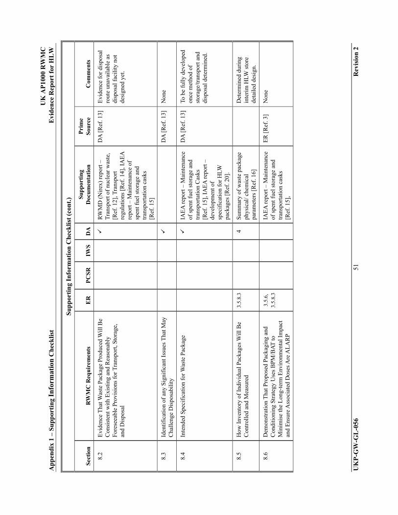
U
K A
P10
00 R
WM
C
Ap
pen
dix
1 –
Su
pp
orti
ng
Info
rmat
ion
Ch
eck
list
Evi
den
ce R
epor
t fo
r H
LW
UK
P-G
W-G
L-0
56
51
Rev
isio
n 2
Su
pp
orti
ng
Info
rmat
ion
Ch
eck
list
(co
nt.
)
Sec
tion
R
WM
C R
equ
irem
ents
E
R
PC
SR
IWS
DA
S
up
por
tin
g D
ocu
men
tati
on
Pri
me
Sou
rce
Com
men
ts
8.2
Evi
denc
e T
hat W
aste
Pac
kage
Pro
duce
d W
ill B
e C
onsi
sten
t with
Exi
stin
g an
d R
easo
nabl
y Fo
rese
eabl
e P
rovi
sion
s fo
r T
rans
port
, Sto
rage
, an
d D
ispo
sal
R
WM
D (
Nir
ex)
repo
rt –
T
rans
port
of
nucl
ear
was
te,
[Ref
. 12]
, Tra
nspo
rt
regu
latio
ns [
Ref
. 14]
, IA
EA
re
port
– M
aint
enan
ce o
f sp
ent f
uel s
tora
ge a
nd
tran
spor
tatio
n ca
sks
[Ref
. 15]
DA
[R
ef. 1
3]
Evi
denc
e fo
r di
spos
al
rout
e un
avai
labl
e as
di
spos
al f
acili
ty n
ot
desi
gned
yet
.
8.3
Iden
tifi
catio
n of
any
Sig
nifi
cant
Iss
ues
Tha
t May
C
halle
nge
Dis
posa
bili
ty
DA
[R
ef. 1
3]
Non
e
8.4
Inte
nded
Spe
cifi
cati
on f
or W
aste
Pac
kage
IAE
A r
epor
t – M
aint
enan
ce
of s
pent
fue
l sto
rage
and
tr
ansp
orta
tion
Cas
ks
[Ref
. 15]
, IA
EA
rep
ort –
de
velo
pmen
t of
spec
ific
atio
n fo
r H
LW
pack
ages
[R
ef. 2
0].
DA
[R
ef. 1
3]
To b
e fu
lly
deve
lope
d on
ce m
etho
d of
st
orag
e/tr
ansp
ort a
nd
disp
osal
det
erm
ined
.
8.5
How
Inv
ento
ry o
f In
divi
dual
Pac
kage
s W
ill B
e C
ontr
olle
d an
d M
easu
red
3.5.
8.3
4 S
umm
ary
of w
aste
pac
kage
ph
ysic
al/ c
hem
ical
pa
ram
eter
s [R
ef. 1
6]
D
eter
min
ed d
urin
g in
teri
m H
LW s
tore
de
tail
ed d
esig
n.
8.6
Dem
onst
rati
on T
hat P
ropo
sed
Pac
kagi
ng a
nd
Con
ditio
ning
Str
ateg
y U
ses
BPM
/BA
T to
M
inim
ise
the
Lon
g-te
rm E
nvir
onm
enta
l Im
pact
an
d E
nsur
e A
ssoc
iate
d D
oses
Are
AL
AR
P
3.5.
6,
3.5.
8.3
IA
EA
rep
ort –
Mai
nten
ance
of
spe
nt f
uel s
tora
ge a
nd
tran
spor
tatio
n ca
sks
[Ref
. 15]
,
ER
[R
ef. 3
] N
one
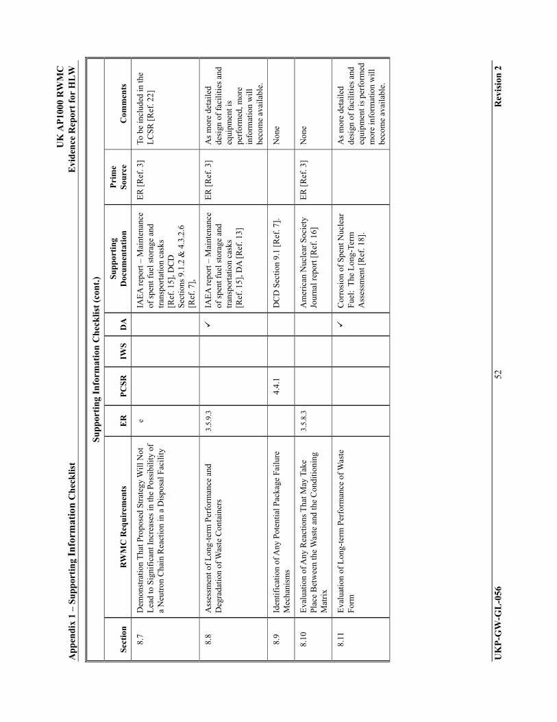
U
K A
P10
00 R
WM
C
Ap
pen
dix
1 –
Su
pp
orti
ng
Info
rmat
ion
Ch
eck
list
Evi
den
ce R
epor
t fo
r H
LW
UK
P-G
W-G
L-0
56
52
Rev
isio
n 2
Su
pp
orti
ng
Info
rmat
ion
Ch
eck
list
(co
nt.
)
Sec
tion
R
WM
C R
equ
irem
ents
E
R
PC
SR
IWS
DA
S
up
por
tin
g D
ocu
men
tati
on
Pri
me
Sou
rce
Com
men
ts
8.7
Dem
onst
rati
on T
hat P
ropo
sed
Stra
tegy
Wil
l Not
L
ead
to S
igni
fica
nt I
ncre
ases
in th
e Po
ssib
ility
of
a N
eutr
on C
hain
Rea
ctio
n in
a D
ispo
sal F
acil
ity
e
IAE
A r
epor
t – M
aint
enan
ce
of s
pent
fue
l sto
rage
and
tr
ansp
orta
tion
cask
s [R
ef. 1
5], D
CD
S
ecti
ons
9.1.
2 &
4.3
.2.6
[R
ef. 7
],
ER
[R
ef. 3
] To
be
incl
uded
in th
e L
CSR
[R
ef. 2
2]
8.8
Ass
essm
ent o
f L
ong-
term
Per
form
ance
and
D
egra
dati
on o
f Was
te C
onta
iner
s 3.
5.9.
3
IA
EA
rep
ort –
Mai
nten
ance
of
spe
nt f
uel s
tora
ge a
nd
tran
spor
tatio
n ca
sks
[Ref
. 15]
, DA
[R
ef. 1
3]
ER
[R
ef. 3
] A
s m
ore
deta
iled
de
sign
of
faci
liti
es a
nd
equi
pmen
t is
perf
orm
ed, m
ore
info
rmat
ion
wil
l be
com
e av
aila
ble.
8.9
Iden
tifi
catio
n of
Any
Pot
enti
al P
acka
ge F
ailu
re
Mec
hani
sms
4.
4.1
DC
D S
ecti
on 9
.1 [
Ref
. 7].
Non
e
8.10
E
valu
atio
n of
Any
Rea
ctio
ns T
hat M
ay T
ake
Plac
e B
etw
een
the
Was
te a
nd th
e C
ondi
tion
ing
Mat
rix
3.5.
8.3
A
mer
ican
Nuc
lear
Soc
iety
Jo
urna
l rep
ort [
Ref
. 16]
E
R [
Ref
. 3]
Non
e
8.11
E
valu
atio
n of
Lon
g-te
rm P
erfo
rman
ce o
f W
aste
Fo
rm
C
orro
sion
of
Spen
t Nuc
lear
F
uel:
The
Lon
g-Te
rm
Ass
essm
ent [
Ref
. 18]
.
A
s m
ore
deta
iled
de
sign
of
faci
liti
es a
nd
equi
pmen
t is
perf
orm
ed
mor
e in
form
atio
n w
ill
beco
me
avai
labl
e.

U
K A
P10
00 R
WM
C
Ap
pen
dix
1 –
Su
pp
orti
ng
Info
rmat
ion
Ch
eck
list
Evi
den
ce R
epor
t fo
r H
LW
UK
P-G
W-G
L-0
56
53
Rev
isio
n 2
Su
pp
orti
ng
Info
rmat
ion
Ch
eck
list
(co
nt.
)
Sec
tion
R
WM
C R
equ
irem
ents
E
R
PC
SR
IWS
DA
S
up
por
tin
g D
ocu
men
tati
on
Pri
me
Sou
rce
Com
men
ts
8.12
A
sses
smen
t of
Pot
enti
al f
or G
as G
ener
atio
n fr
om
Was
tes
in th
e L
ong-
term
It is
thou
ght t
hat s
ome
fiss
ion
gase
s w
ill f
orm
bu
t sin
ce th
ey c
anno
t es
cape
fro
m th
e di
spos
al c
anis
ter,
ther
e w
ill b
e no
impa
ct. T
his
area
nee
ds a
ddit
iona
l de
velo
pmen
t.
8.13
C
onsi
dera
tion
of
Impa
ct o
f To
xic
Mat
eria
ls a
s a
Res
ult o
f R
elea
se f
rom
a D
ispo
sal F
acili
ty a
nd
Env
iron
men
tal I
mpa
cts
that
Mig
ht A
rise
Dur
ing,
or
as
a R
esul
t of,
Ope
ratio
ns
3.5.
8.3
4.4
D
CD
Sec
tion
s 9.
1.2
& 6
.2.3
[R
ef. 7
]
Non
e
8.14
A
n A
sses
smen
t of
the
Pote
ntia
l Im
pact
fro
m a
ny
Det
rim
enta
l eff
ects
due
to C
hem
ical
Spe
cies
that
m
ay b
e pr
esen
t in
the
was
tes
or m
ight
rea
sona
bly
be e
xpec
ted
to f
orm
.
S
umm
ary
of W
aste
Pac
kage
P
hysi
cal/
Che
mic
al
Par
amet
ers
[Ref
. 16]
DA
[R
ef. 1
3]
Non
e
8.15
H
ow C
ondi
tion
ed W
aste
Tha
t Doe
s N
ot M
eet
Spec
ific
atio
ns W
ill B
e M
anag
ed
2.8.
2
DC
D S
ecti
on 9
.1.4
[R
ef. 7
] E
R [
Ref
. 3]
Non
e
8.16
A
rran
gem
ents
for
Qua
lity
Ass
uran
ce a
nd R
ecor
ds
1.4
1.5.
2 3.
2,
3.3
E
A g
uida
nce
on m
anag
ing
info
rmat
ion
[Ref
. 6],
IA
EA
re
port
– D
ata
Req
uire
men
ts
and
mai
nten
ance
of
reco
rds
for
spen
t fue
l man
agem
ent:
A
rev
iew
[R
ef. 1
9], L
CSR
S
ecti
on 3
[R
ef. 2
2], Q
MS
[R
ef. 2
4], P
roje
ct Q
uali
ty
Pla
n [R
ef. 2
5]
ER
[R
ef. 3
] W
ill b
e de
velo
ped
duri
ng d
etai
led
desi
gn
of f
acil
itie
s.
8.17
H
ow D
evel
opm
ents
in D
ispo
sal F
acil
ity
Req
uire
men
ts W
ill B
e Ta
ken
Into
Acc
ount
n/
a n/
a n/
a n/
a n/
a n/
a N
one

U
K A
P10
00 R
WM
C
Ap
pen
dix
1 –
Su
pp
orti
ng
Info
rmat
ion
Ch
eck
list
Evi
den
ce R
epor
t fo
r H
LW
UK
P-G
W-G
L-0
56
54
Rev
isio
n 2
Su
pp
orti
ng
Info
rmat
ion
Ch
eck
list
(co
nt.
)
Sec
tion
R
WM
C R
equ
irem
ents
E
R
PC
SR
IWS
DA
S
up
por
tin
g D
ocu
men
tati
on
Pri
me
Sou
rce
Com
men
ts
9 ST
OR
AG
E O
F R
AD
IOA
CT
IVE
WA
ST
E
9.1
Stor
age
Cap
acit
y R
equi
rem
ents
2.
8.2
3.5.
7.3
2.
2.4
D
CD
Sec
tion
9.1
.2.1
[R
ef. 7
], P
roce
ss m
ass
bala
nce
for A
P10
00 s
olid
w
aste
[R
ef. 2
6]
ER
[R
ef. 3
] N
one
9.2
Tim
esca
le f
or S
tora
ge
3.5.
8.3
ER
[R
ef. 3
] W
ill b
e de
tail
ed f
urth
er
duri
ng d
etai
led
desi
gn
of H
LW in
teri
m s
tora
ge
faci
lity.
9.3
Dem
onst
rati
on T
hat C
ondi
tion
ed W
aste
s W
ill
Rem
ain
Wit
hin
Agr
eed
Spe
cifi
catio
n fo
r F
inal
D
ispo
sal T
hrou
ghou
t the
Sto
rage
Per
iod
3.5.
8.3
DA
[R
ef. 1
3]
ER
[R
ef. 3
] A
ltho
ugh
DA
giv
es
conf
iden
ce th
at th
at th
e w
aste
wil
l rem
ain
wit
hin
agre
ed
spec
ific
atio
n,
addi
tiona
l wor
k is
re
quir
ed to
dem
onst
rate
th
is.
9.4
How
Pas
sive
Saf
ety
Will
Be
Ach
ieve
d 3.
5 6.
5.13
, 6.
5.23
D
CD
Sec
tion
9.1
[R
ef. 7
],
IAE
A r
epor
t – M
aint
enan
ce
of s
pent
fue
l sto
rage
and
tr
ansp
orta
tion
cask
s [R
ef. 1
5]
ER
[R
ef. 3
] T
his
info
rmat
ion
wil
l be
com
plet
ed d
urin
g th
e de
tail
ed d
esig
n of
th
e H
LW in
teri
m s
tore
.
9.5
Inte
grit
y of
Sto
rage
Arr
ange
men
ts
3.5.
8.3
3,5,
7,3
DC
D S
ecti
ons
3.2
and
9.1
[Ref
. 7],
IA
EA
rep
ort –
M
aint
enan
ce o
f sp
ent f
uel
stor
age
and
tran
spor
tati
on
cask
s [R
ef. 1
5], D
A
[Ref
. 13]
ER
[R
ef. 3
] T
his
info
rmat
ion
wil
l be
com
plet
ed d
urin
g th
e de
tail
ed d
esig
n of
th
e H
LW in
teri
m s
tore
.

U
K A
P10
00 R
WM
C
Ap
pen
dix
1 –
Su
pp
orti
ng
Info
rmat
ion
Ch
eck
list
Evi
den
ce R
epor
t fo
r H
LW
UK
P-G
W-G
L-0
56
55
Rev
isio
n 2
Su
pp
orti
ng
Info
rmat
ion
Ch
eck
list
(co
nt.
)
Sec
tion
R
WM
C R
equ
irem
ents
E
R
PC
SR
IWS
DA
S
up
por
tin
g D
ocu
men
tati
on
Pri
me
Sou
rce
Com
men
ts
9.6
Arr
ange
men
ts f
or L
eak
Det
ecti
on
6.2.
1,
3.5.
8.3
D
CD
Sec
tion
s 9.
4.3,
11.
5,
9.13
& 1
2.2.
2 [R
ef. 7
], S
KB
B
roch
ure
[Ref
. 21]
, IA
EA
re
port
– O
pera
tion
and
m
aint
enan
ce o
f sp
ent f
uel
stor
age
and
tran
spor
tati
on
cask
s [R
ef. 1
5].
ER
[R
ef. 3
] T
his
info
rmat
ion
wil
l be
com
plet
ed d
urin
g th
e de
tail
ed d
esig
n of
th
e H
LW in
teri
m s
tore
.
9.7
Det
ails
of
Ven
tilat
ion
Req
uire
men
ts a
nd F
iltr
atio
n of
Air
born
e R
elea
ses
3.3.
3 3.
3.2.
2
3.5.
8.3
ER
[R
ef. 3
] T
his
info
rmat
ion
wil
l be
com
plet
ed d
urin
g th
e de
tail
ed d
esig
n of
th
e H
LW in
teri
m s
tore
.
9.8
Env
iron
men
tal M
onito
ring
Arr
ange
men
ts
6
E
R [
Ref
. 3]
Thi
s in
form
atio
n w
ill
be c
ompl
eted
dur
ing
the
deta
iled
des
ign
of
the
HLW
inte
rim
sto
re.
9.9
How
Sto
red
Was
te W
ill B
e R
etri
eved
and
In
spec
ted
3.5.
8.3
ER
[R
ef. 3
] T
his
info
rmat
ion
wil
l be
com
plet
ed d
urin
g th
e de
tail
ed d
esig
n of
th
e H
LW in
teri
m s
tore
.
9.10
H
ow P
acka
ges
Tha
t Sho
w E
vide
nce
of D
evia
ting
fr
om S
peci
fica
tion
Dur
ing
Stor
age
Will
Be
Man
aged
IAE
A r
epor
t – d
evel
opm
ent
of s
peci
fica
tion
for
HLW
pa
ckag
es [
Ref
. 20]
.
T
his
info
rmat
ion
wil
l be
com
plet
ed d
urin
g th
e de
tail
ed d
esig
n of
th
e H
LW in
teri
m s
tore
.

U
K A
P10
00 R
WM
C
Ap
pen
dix
1 –
Su
pp
orti
ng
Info
rmat
ion
Ch
eck
list
Evi
den
ce R
epor
t fo
r H
LW
UK
P-G
W-G
L-0
56
56
Rev
isio
n 2
Su
pp
orti
ng
Info
rmat
ion
Ch
eck
list
(co
nt.
)
Sec
tion
R
WM
C R
equ
irem
ents
E
R
PC
SR
IWS
DA
S
up
por
tin
g D
ocu
men
tati
on
Pri
me
Sou
rce
Com
men
ts
10
CO
NT
RO
L, A
CC
OU
NTA
NC
Y, A
ND
R
EC
OR
DS
10.1
A
rran
gem
ents
for
Rec
ordi
ng I
nfor
mat
ion
Tha
t M
ay B
e R
equi
red
in F
utur
e to
Fac
ilita
te
Subs
eque
nt M
anag
emen
t of
Rad
ioac
tive
Su
bsta
nces
and
Fac
ilit
ies
3.2,
3.
3
EA
gui
danc
e on
man
agin
g in
form
atio
n re
lati
ng to
ra
dioa
ctiv
e w
aste
in th
e U
nite
d K
ingd
om [
Ref
. 6],
IA
EA
rep
ort –
Dat
a re
quir
emen
ts a
nd
mai
nten
ance
of
reco
rds
for
spen
t fue
l man
agem
ent:
A
revi
ew [
Ref
. 19]
, IA
EA
re
port
– d
evel
opm
ent o
f sp
ecif
icat
ion
for
HLW
pa
ckag
es [
Ref
. 20]
, LC
SR
Sec
tion
9.3
.5 [
Ref
. 22]
, UK
R
adio
acti
ve W
aste
In
vent
ory
[Ref
. 0].
T
his
info
rmat
ion
wil
l be
inco
rpor
ated
into
the
proc
edur
es w
ritt
en b
y th
e li
cens
ee
10.2
O
ngoi
ng M
easu
res
to D
emon
stra
te W
heth
er
Com
plia
nce
wit
h R
equi
rem
ents
and
Sta
ndar
ds
Has
Bee
n A
chie
ved
EA
gui
danc
e on
man
agin
g in
form
atio
n re
lati
ng to
ra
dioa
ctiv
e w
aste
in th
e U
nite
d K
ingd
om [
Ref
. 6],
IA
EA
rep
ort –
Dat
a re
quir
emen
ts a
nd
mai
nten
ance
of
reco
rds
for
spen
t fue
l man
agem
ent:
A
revi
ew [
Ref
. 19]
, IA
EA
re
port
– d
evel
opm
ent o
f sp
ecif
icat
ion
for
HLW
pa
ckag
es [
Ref
. 20]
, LC
SR
[Ref
. 22]
.
T
his
info
rmat
ion
wil
l be
inco
rpor
ated
into
the
proc
edur
es w
ritt
en b
y th
e li
cens
ee

U
K A
P10
00 R
WM
C
Ap
pen
dix
1 –
Su
pp
orti
ng
Info
rmat
ion
Ch
eck
list
Evi
den
ce R
epor
t fo
r H
LW
UK
P-G
W-G
L-0
56
57
Rev
isio
n 2
Su
pp
orti
ng
Info
rmat
ion
Ch
eck
list
(co
nt.
)
Sec
tion
R
WM
C R
equ
irem
ents
E
R
PC
SR
IWS
DA
S
up
por
tin
g D
ocu
men
tati
on
Pri
me
Sou
rce
Com
men
ts
10.3
T
imes
cale
s ov
er W
hich
Suc
h In
form
atio
n S
hall
B
e R
ecor
ded
and
Ret
aine
d
E
A g
uida
nce
on m
anag
ing
info
rmat
ion
rela
ting
to
radi
oact
ive
was
te in
the
Uni
ted
Kin
gdom
[R
ef. 6
],
IAE
A r
epor
t – D
ata
requ
irem
ents
and
m
aint
enan
ce o
f re
cord
s fo
r sp
ent f
uel m
anag
emen
t: A
re
view
[R
ef. 1
9], I
AE
A
repo
rt –
dev
elop
men
t of
spec
ific
atio
n fo
r H
LW
pack
ages
[R
ef. 2
0], L
CSR
S
ecti
on 9
.3.5
[R
ef. 2
2].
T
his
info
rmat
ion
wil
l be
inco
rpor
ated
into
the
proc
edur
es w
ritt
en b
y th
e li
cens
ee
10.4
E
nvir
onm
enta
l Con
ditio
ns f
or S
tora
ge a
nd L
ong-
term
Pre
serv
atio
n of
Rec
ords
E
A g
uida
nce
on m
anag
ing
info
rmat
ion
rela
ting
to
radi
oact
ive
was
te in
the
Uni
ted
Kin
gdom
[R
ef. 6
],
IAE
A r
epor
t – D
ata
requ
irem
ents
and
m
aint
enan
ce o
f re
cord
s fo
r sp
ent f
uel m
anag
emen
t: A
re
view
[R
ef. 1
9].
T
his
info
rmat
ion
wil
l be
inco
rpor
ated
into
the
proc
edur
es w
ritt
en b
y th
e li
cens
ee

UK AP1000 RWMC Appendix 2 – Glossary Evidence Report for HLW
UKP-GW-GL-056 58 Revision 2
APPENDIX 2 GLOSSARY OF TERMS

UK AP1000 RWMC Appendix 2 – Glossary Evidence Report for HLW
UKP-GW-GL-056 59 Revision 2
Glossary of Terms
ALARP As Low As Reasonably Practicable
BAT Best Available Techniques
BPM Best Practicable Means
CFA Conditions For Acceptance
DCD AP1000 European Design Control Document
DCTC Disposal Canister Transport Container
EA Environment Agency
ER Environment Report
FMECA Failure Mode Effect and Criticality Analysis
GDA Generic Design Assessment
GDF Geological Disposal Facility
HEPA High Efficiency Particulate Air
HLW High Level Waste
HSE Health and Safety Executive
HSW Health & Safety at Work
IAEA International Atomic Energy Agency
ILW Intermediate Level Waste
IWS Integrated Waste Management Strategy
LCSR Plant Lifecycle Safety Report
LLW Low Level Waste
MPC Multi-purpose Container
ND Nuclear Directorate
NISR Nuclear Industries Security Regulations
NPP Nuclear Power Plant
OCNS Office for Civil Nuclear Safety
PCSR Pre-Construction Safety Report
QA Quality Assurance
RWMC Radioactive Waste Management Case
RWMD Radioactive Waste Management Directorate
SAP Safety Assessment Principle
SEPA Scottish Environment Protection Agency

UK AP1000 RWMC Appendix 2 – Glossary Evidence Report for HLW
UKP-GW-GL-056 60 Revision 2
Glossary of Terms (cont.)
SKB Svensk Kärnbränslehantering AB
UKSO United Kingdom Safeguards Office
U.S. United States
VLLW Very Low Level Radioactive Waste
Westinghouse/ Westinghouse Electric Company
UK AP1000 RWMC Appendix 3 – Spent Fuel Disposability Plan Evidence Report for HLW
UKP-GW-GL-056 61 Revision 2
APPENDIX 3 SPENT FUEL DISPOSABILITY PLAN

U
K A
P10
00 R
WM
C
Ap
pen
dix
3 –
Sp
ent
Fu
el D
isp
osab
ilit
y P
lan
E
vid
ence
Rep
ort
for
HL
W
UK
P-G
W-G
L-0
56
62
Rev
isio
n 2
Fig
ure
A3-
1. S
pen
t F
uel
Dis
pos
abil
ity
Pla
n