west placer storm water quality design manual pdf
TRANSCRIPT

West Placer
Storm Water Quality Design Manual
April 2016
Revised May 2018
Acknowledgements
Project Sponsors and Funding
Preparation of this document was funded in part from the Cooperative Endangered
Species Conservation Fund (Section 6) Planning Grants administered by the California
Department of Fish and Wildlife through Agreement No P1382019 The Agreement is for
several work products including this document Additional funding and in-kind services
were provided by the County of Placer the City of Roseville the City of Auburn the City of
Lincoln and the Town of Loomis In-kind services were provided by the Technical
Advisory Committee members Paid consultants were cbec eco engineering inc and CDM
Smith
Steering Committee
Jennifer Byous Placer County Jennifer Hanson City of Lincoln
Rebecca Taber PE Placer County Gorman Lau PE Larry Walker Associates representing City of Lincoln
Mary Keller PE CFM QSD Placer County
Brit Snipes Town of Loomis
Candace Rousselet Placer County Bernie Schroeder City of Auburn
Chris Kraft PE City of Roseville Edgar Medina City of Auburn
Technical Advisory CommitteeJack Paddon
Williams and Paddon Architects + Planners Inc
Harvey Oslick
Wood Rogers Inc
Craig Seltenrich
Dudek
Thomas Plummer
Civil Engineering Solutions Inc
Ryan OrsquoKeefe
West Park Communities
Steve Fuhrman
Fuhrman Leamy Land Group
Gregg Bates
Dry Creek Conservancy
Ron Enz
McKay amp Somps
Ron Wood
RFE Engineering Inc
Consultant Teamcbec eco engineering inc CDM Smith
Chris Bowles PhD PE Melanie Carr MS PE Scott Walls MLAEP
Stefan Schuster PE
Steven Wolosoff BCES
Russell Vadenais PE
Nola Mitchell EIT
Questions or comments about the Manual should be directed to local jurisdiction storm
water program staff in the jurisdictional agency where the proposed project is located
Web Site (download Manual here)
httpwwwplacercagovlowimpactdevelopment
Disclaimer
The contents of this Manual do not necessarily represent the policies of the supporting
agencies as identified on the cover page Although every reasonable effort has been made
to ensure the integrity of the document the supporting agencies do not make any
warranty or representation expressed or implied with respect to the accuracy or
completeness of the information contained herein
The storm water controls described herein are intended to meet the minimum standard
of ldquoreducing the discharge of pollutants from their MS4s to waters of the US to the
maximum extent practicablerdquo as required the State Water Resources Control Board Water
Quality Order No 2013-001-DWQ National Pollutant Discharge Elimination System
(NPDES) General Permit No CAS000004 Waste Discharge Requirements for Storm Water
Discharges from Small MS4s Other permit requirements may apply and it is the
responsibility of the project owner to ensure compliance with all applicable regulations
Mention of trade names or commercial products does not constitute endorsement or
recommendation of those products
Table of Contents
Chapter 1 Introduction 1-111 Regulatory Background 1-2shy12 Purpose of this Manual1-3shy13 Use of Outside References1-4shy14 How This Manual Relates to Other Requirements 1-5shy15 Manual Revision Process1-5shy
Chapter 2 Projects Subject to Requirements 2-121 Project Location 2-1shy22 Project Categorization 2-4shy23 Exclusions2-7shy24 Project Submittal and Approval Process2-8shy
Chapter 3 Pre-Project Site Assessment 3-131 Site Assessment3-1shy
311 Soil Geologic and Groundwater Characteristics3-2shy312 Topography Hydrology and Drainage Characteristics 3-4shy313 Existing Vegetation and Natural Areas 3-5shy314 Contaminated Soil or Groundwater 3-6shy315 Existing Improvements and Easements3-6shy
Chapter 4 Site Planning and BMP Selection 4-141 Small Projects4-1shy42 Regulated Projects 4-2shy
421 Site Plan Layout 4-4shy422 Source Control Measures 4-6shy423 Site Design Measures (LID BMP Selection)4-8shy424 Storm Water Treatment and Baseline Hydromodification Management 4-10shy
43 Hydromodification Management Projects 4-12shy44 In Lieu Program 4-13shy
Chapter 5 BMP Inspection Operation and Maintenance 5-151 Operation and Maintenance Submittal Requirements at the Permitting Stage5-1shy52 Annual Self-Certification Reports 5-1shy
Chapter 6 Developing a Post-Construction Storm Water Quality Plan (SWQP) 6-1Using the SWQP Template (Appendix A)6-2shyTitle Page6-2shySection 1 General Project Information6-2shySection 2 Requirements for Small Projects6-3shySection 3 Requirements for Regulated Projects6-6shySection 4 Requirements for Hydromodification Management Projects 6-16shySection 5 Inspection and Maintenance of Post-Construction BMPs 6-21shySection 6 Compliance Checklist 6-21shy
i
11
Table of Contents
Glossary
List of Figures
Figure 2-1 Phase II MS4 Permit Regulatory Boundaries 2-2shyFigure 2-2 CARP Regulatory Boundaries 2-3shyFigure 2-3 Project Category Decision Tree 2-4shyFigure 2-4 SWQP Development and Submittal Process 2-8shyFigure 4-1 Site Plan Example 4-5shyFigure 4-2 Selection of Storm Water TreatmentBaseline Hydromodification Controls 4-
List of Tables
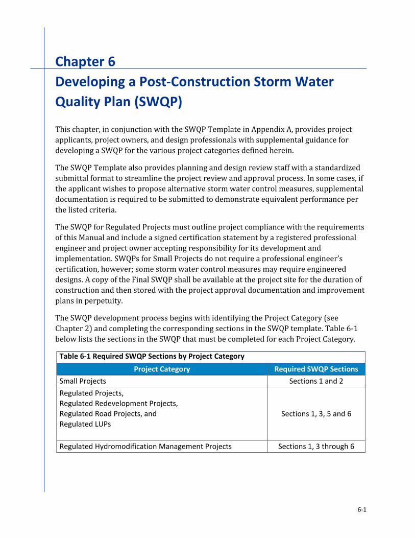
Table 2-1 Project Categories 2-5shyTable 2-2 Special Case Regulated Projects 2-6shyTable 4-1 Selection of Site Design Measures for Small Projects1 4-2shyTable 4-2 Selection of Site Design Measures for Regulated Projects1 4-9shyTable 6-1 Required SWQP Sections by Project Category 6-1shy
Appendices
Appendix A Automated Template for Post-Construction Storm Water Quality PlanAppendix B Site Design Measures Fact SheetsAppendix C Source Control Measures Selection TableAppendix DSWQP Examples
Chapter 1Introduction
This Storm Water Quality Design Manual (Manual) has been developed cooperatively
between Placer County the City of Roseville the City of Lincoln the City of Auburn and
the Town of Loomis to provide a consistent approach to address storm water
management within the West Placer region For the purposes of this Manual the West
Placer region refers to the areas of Placer County subject to the requirements of this
Manual as described in Chapter 2
As development transforms undeveloped
lands with impervious surfaces such as
pavement concrete buildings or even
compacted soils the natural infiltration of
rainfall into the soil and absorption of rainfall by vegetation is inhibited This reduction of
natural retention of rainfall increases the
frequency and intensity of surface runoff which can mobilize and transport sediment
and pollutants into our lakes streams and
wetlands The resulting changes in runoff patterns can also disrupt natural streams
through a process known as
hydromodification causing impacts such as
increased channel erosion flooding loss of
habitat and damage to aquatic ecosystems
The State of California together with local
municipalities have developed storm water
management strategies to address the
adverse effects of development by
implementing regulations and storm water
management programs to preserve our
waterways and natural hydrologic processes Storm water permits across the country
now include requirements for low impact development (LID) strategies that focus on
preserving key elements of a project sitersquos pre-development hydrologic function
LID is a design strategy where storm water runoff is treated as a valuable resource that
can recharge groundwater supplies protect and enhance natural habitat and biodiversity
and add value to new development or redevelopment projects Rather than discharging
storm water runoff as a waste product projects are designed to include a diverse set of
Hydrologic changes caused by development can damage our natural waterways Photo Credit ndash Placer County
1-1
Chapter 1 bull Introduction West Placer Storm Water Quality Design Manual
post-construction storm water controls or Best Management Practices (BMPs) that
infiltrate evapotranspire or biotreat storm water runoff By retaining storm water runoff on-site downstream receiving waters are provided with protection from increased
pollutant loads and alterations of hydrologic functions otherwise impacted by increased
impervious surfaces and human activities By protecting receiving waters LID strategies
help maintain beneficial uses of these resources including potable water sources
recreational uses and fisheries LID can also add value to new development and
redevelopment by integrating storm water management features with landscaping and
other improvements rather than the more traditional approach of constructing drainage
impact mitigation measures (eg detention basins) as disconnected often fenced off features
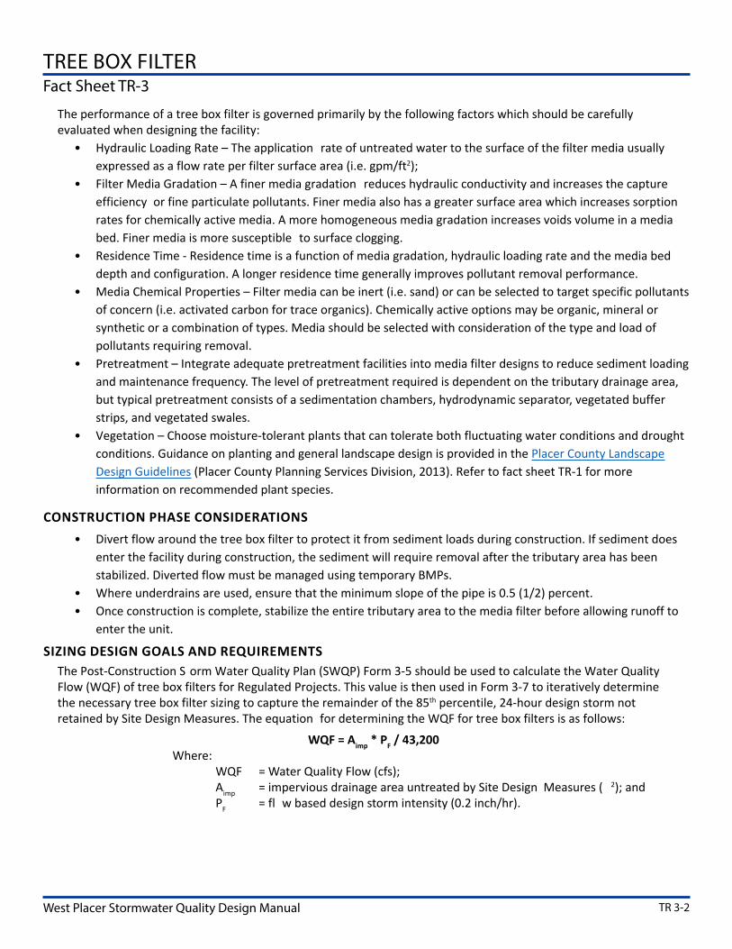
The intent of this Manual is to
promote the following LID goals
degdegdegdeg Minimize adverse impacts ofstorm water runoff on waterquality biological integrity ofreceiving waters and beneficialuses of water bodies
degdegdegdeg Minimize the percentage ofimpervious surfaces on landdevelopment projects andimplement mitigationmeasures
to approximatelypreserve the
overall pre-development water
balancethrough infiltrationevapotranspiration andcapture
and use of storm water
degdegdegdeg Minimize pollutant loadings from impervious surfaces such as roof tops parking
lots and roadways through the use of properly designed technically appropriate
storm water controls including source control measures or good housekeeping
practices LID planning and design strategies and treatment control BMPs
degdegdegdeg Guide proper selection design and maintenance of storm water BMPs to address
pollutants generated by land development minimize post-development surface
flows and velocities assure long-term functionality of BMPs and avoid vector
breeding
11 Regulatory Background Local storm water regulations originate from federal regulations that began in 1987
when the Clean Water Act (CWA) was amended by the Water Quality Act to formally
include storm water runoff Congress subsequently authorized the US Environmental
By directing storm water to natural or landscaped areas rather than efficiently conveying it to the nearest water body we protect our natural water resources Photo Credit ndash Greg Bates
1-2
West Placer Storm Water Quality Design Manual Chapter 1 bull Introduction
Protection Agency (EPA) to administer the National Pollutant Discharge Elimination
System (NPDES) program and issue storm water permits to municipalities regulating
storm water discharges In California this authority was delegated from EPA to the
California State Water Resources Control Board (SWRCB) and associated Regional Water
Quality Control Boards (RWQCBs)
In addition to storm water regulations RWQCBs certify that permits under Section 404 of
the CWA issued by the US Army Corps of Engineers (Corps) meet state water quality
requirements pursuant to Section 401 of the CWA The 401 certification program
provides for protection of the physical chemical and biological integrity of waters Also
pursuant to the Porter-Cologne Water Quality Act adopted by the state RWQCBs also
regulate activities that impact ldquoWaters of the Staterdquo which include certain wetlands and
waters not regulated by the Corps
The Central Valley RWQCB (CVRWQCB) is responsible for issuing NPDES permits and
401 certifications in the West Placer region NPDES Municipal Separate Storm Sewer
System (MS4) Permits require municipalities to implement a variety of programs to
prevent pollution improve and protect storm water quality reduce storm water runoff and enhance the ecologic vitality of local creeks and waterways MS4 Permits also require
that municipalities regulate new development and redevelopment projects within their
jurisdiction
12 Purpose of this Manual This Manual provides guidance for projects that are required to comply with CWA
regulations and presents LID design standards to reduce runoff treat storm water and
provide baseline hydromodification management This Manual is a regulatory compliance
tool that addresses the requirements of the SWRCB Water Quality Order No 2013-001-DWQ NPDES General Permit No CAS000004 Waste Discharge Requirements for Storm
Water Discharges from Small MS4s (Phase II MS4 Permit)
Consistent with the CWA and the Phase II MS4 Permit this Manual requires storm water
controls to reduce pollutants to the maximum extent practicable (MEP) The MEP
standard is an ever-evolving flexible and advancing concept which considers technical
and economic feasibility Interpretation of the MEP standard will be by the jurisdictional
agency that has discretion over the project
The process of developing a Storm Water Quality Plan (SWQP) for new and
redevelopment projects is outlined in this Manual and a SWQP Template is provided in
Appendix A The SWQP documents a projectrsquos compliance with the Phase II MS4 Permit
and provides a standardized format for complete and accurate analyses which will result
in more efficient design review and project approval
The following websites are available to view additional information regarding each
jurisdictionrsquos storm water program activities
1-3
Chapter 1 bull Introduction West Placer Storm Water Quality Design Manual
wwwplacercagovstormwater
wwwrosevillecausstormwater
The reader is encouraged to review Section E12 - Post Construction Storm Water
Management Program of the Phase II MS4 Permit which can be found at the following
website
httpwwwwaterboardscagovwater_issuesprogramsstormwaterphase_ii_m
unicipalshtml
In addition to the Phase II MS4 Permit this Manual addresses requirements under Placer
County Aquatic Resources Program (CARP) The CARP is currently under development
and once the program is approved this Manual will be updated to incorporate guidance
for using LID strategies to minimize impact to aquatic resources The reader is
encouraged to review the draft CARP document which can be found at the following
website
httpwwwplacercagov~mediacdrPlanningPCCPPolicyDoc2011Append
ix20Mpdf
13 Use of Outside References Throughout this Manual several website references are made to assist the designer with
the SWQP development The following websites provide certain baseline information that
is applicable to the understanding and development of the plan
degdegdegdeg Placer County Stormwater Management Manual (SWMM)
httpwwwplacercagov~mediadpwflood20controldocumentsSwmm2
004pdf
degdegdegdeg Placer County Planning Division
httpwwwplacercagovDepartmentsCommunityDevelopmentPlanningaspx
degdegdegdeg Natural Resources Conservation Service Web Soil SurveyshyhttpwebsoilsurveynrcsusdagovappHomePagehtmshy
degdegdegdeg Natural Resources Conservation Service TR-55 ManualshyhttpwwwhydrocadnetpdfTR-5520Manualpdfshy
degdegdegdeg California State Water Resources Control Board Database of RegisteredshyContaminated Sitesshy
SWRCB httpgeotrackerwaterboardscagov
degdegdegdeg US EPA Brownfields InformationshyEPA Brownfield httpwwwepagovbrownfieldsshy
1-4
West Placer Storm Water Quality Design Manual Chapter 1 bull Introduction
degdegdegdeg CA Department of Toxic Substances Control Former Brownfields and Agricultural
Sites
httpwwwdtsccagovSiteCleanupBrownfields
httpwwwdtsccagovSiteCleanupCortese_Listcfm
degdegdegdeg California Stormwater Quality Associationshywwwcasqaorgresourcesbmp-handbooksshy
degdegdegdeg California State Water Resources Control Board Impaired Water Bodies Information
wwwwaterboardscagovwater_issuesprogramswater_quality_assessmenti
mpaired
14 How This Manual Relates to Other Requirements This Manual is intended to satisfy the specific requirements of the Phase II MS4 Permit
and CARP as discussed above Additional design requirements imposed by other
regulations and permits such as construction and industrial permits local grading
ordinances CAL Green California Environmental Quality Act (CEQA) and hydraulic
design for flood control still apply as appropriate The governing agencies overseeing
these regulations may at their discretion determine that designs in accordance with this
Manual satisfies another requirement Additionally coverage under another regulation
may trigger the requirement to design in accordance with this Manual Please check with
the local governing agency for specific requirements
15 Manual Revision Process It is recognized that LID is an emerging field and that while every effort has been made to
ensure that this Manual is complete and accurate revisions andor amendments may be
necessary In addition the Phase II MS4 Permit and CARP are on a 5-year reissuance
cycle which may trigger required updates to this Manual It is anticipated that Manual
revisions will generally coincide with Phase II MS4 Permit revisions following a 5-year
revision schedule The current Phase II MS4 Permit expires in June 2018
Administrative revisions to improve permit processing and correct problems outside of
the next scheduled Phase II MS4 Permit revision shall be authorized cooperatively by the
participating jurisdictionsrsquo Directors (or their designee responsible for Storm Water
compliance) These jurisdiction include the County of Placer the City of Roseville the City
of Lincoln the City of Auburn and the Town of Loomis
1-5
Chapter 1 bull Introduction West Placer Storm Water Quality Design Manual
This page intentionally left blank
1-6
Chapter 2Projects Subject to Requirements
The post-construction storm water control requirements described herein apply to new
development and redevelopment projects approved after July 1 2015 These
requirements vary depending on the projectrsquos location and the amount of impervious
surface that is being created This chapter introduces a categorization process to define
the project type and then determine the corresponding storm water requirements
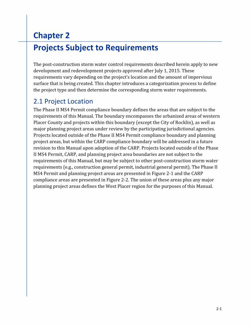
21 Project Location The Phase II MS4 Permit compliance boundary defines the areas that are subject to the
requirements of this Manual The boundary encompasses the urbanized areas of western
Placer County and projects within this boundary (except the City of Rocklin) as well as
major planning project areas under review by the participating jurisdictional agencies
Projects located outside of the Phase II MS4 Permit compliance boundary and planning
project areas but within the CARP compliance boundary will be addressed in a future
revision to this Manual upon adoption of the CARP Projects located outside of the Phase
II MS4 Permit CARP and planning project area boundaries are not subject to the
requirements of this Manual but may be subject to other post-construction storm water
requirements (eg construction general permit industrial general permit) The Phase II MS4 Permit and planning project areas are presented in Figure 2-1 and the CARP
compliance areas are presented in Figure 2-2 The union of these areas plus any major
planning project areas defines the West Placer region for the purposes of this Manual
2-1
Chapter 2 bull Phase II MS4 Permit Requirements West Placer Storm Water Quality Design Manual
Figure 2-1Phase II MS4 Permit Regulatory Boundaries
2-2
West Placer Storm Water Quality Design Manual Chapter 2 bull Phase II MS4 Permit Requirements
Figure 2-2CARP Regulatory Boundaries
2-3
Chapter 2 bull Phase II MS4 Permit Requirements West Placer Storm Water Quality Design Manual
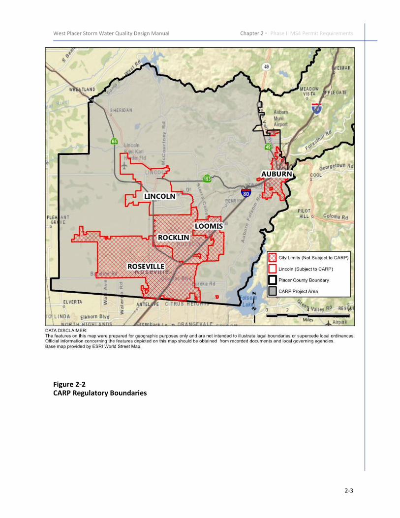
22 Project Categorization The distinction between Small Projects and Regulated Projects is based on the amount of
impervious surface that is created or replaced The decision tree below may be used to
assist in determining the project category
Does the project create andor replace between 2500 ft2 and 5000 ft2 of impervious surface
Small
Project
Regulated
Project
Hydromodification
Management Project
Required
Yes
No Does the project create andor replace one acre or more of impervious surface and
include an increase in impervious surface
Yes
No
No
Yes
Not Subject to the
Requirements of this
Manual2
Is the project type included in the exclusions listed in Section 23
Is the project a detached single family not part of a larger plan of development Yes
No
Is the project within the Phase II MS4 Permit Areas or Planning Project
Areas1 depicted in Figure 2-1
Does the project create more than 2500 ft2 of impervious surface
No
No
Yes
Yes
1 Future planning projects not shown on Figure 2-1 may be subject to this Manualas determined by the jurisdictional agency
2 Projects located within the CARP Boundary in Figure 2-2 may be subject to futurerequirements upon adoption of the CARP Other SWRCB General Orders (egConstruction General Permit Industrial General Permit) may apply to a project
Figure 2-3 Project Category Decision Tree
2-4
-
West Placer Storm Water Quality Design Manual Chapter 2 bull Phase II MS4 Permit Requirements
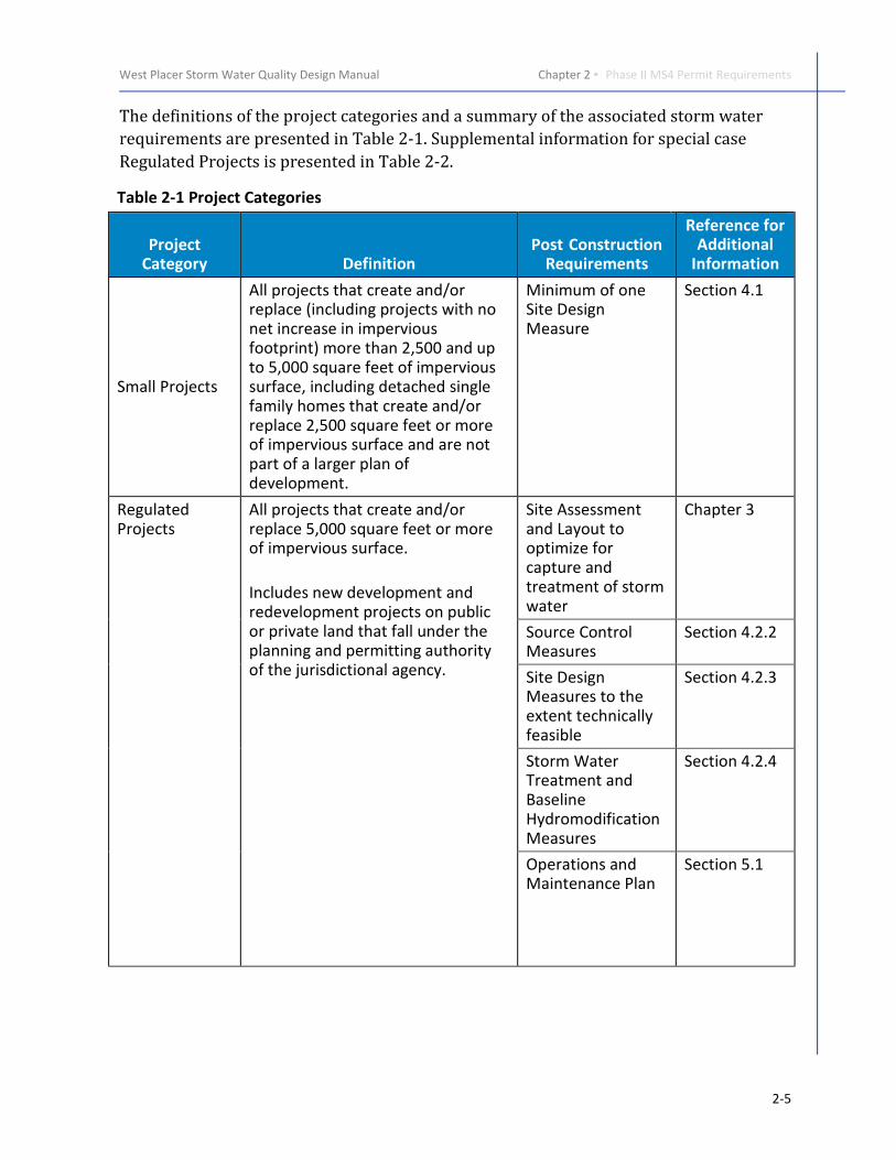
The definitions of the project categories and a summary of the associated storm water
requirements are presented in Table 2-1 Supplemental information for special case
Regulated Projects is presented in Table 2-2
Table 2-1 Project Categories
Project Category Definition
Post Construction Requirements
Reference for Additional
Information
Small Projects
All projects that create andor replace (including projects with no net increase in impervious footprint) more than 2500 and up to 5000 square feet of impervious surface including detached single family homes that create andor replace 2500 square feet or more of impervious surface and are not part of a larger plan of development
Minimum of one Site Design Measure
Section 41
Regulated Projects
All projects that create andor replace 5000 square feet or more of impervious surface
Includes new development and redevelopment projects on public or private land that fall under the planning and permitting authority of the jurisdictional agency
Site Assessment and Layout to optimize for capture and treatment of storm water
Chapter 3
Source Control Measures
Section 422
Site Design Measures to the extent technically feasible
Section 423
Storm Water Treatment and Baseline Hydromodification Measures
Section 424
Operations and Maintenance Plan
Section 51
2-5
-
Chapter 2 bull Phase II MS4 Permit Requirements West Placer Storm Water Quality Design Manual
Table 2-2 Special Case Regulated Projects
Project Category Definition Post Construction Requirements
Regulated Redevelopment Projects
Any land-disturbing activity that results in the creation addition or replacement of 5000 square feet or more exterior impervious surface area on a site on which some past development has occurred
Where a redevelopment project results in an increase equal to or greater than 50 percent of the impervious surface of a previously existing development runoff from the entire project consisting of all existing new andor replaced impervious surfaces must be treated per the requirements for Regulated Projects to the extent feasible
Where a redevelopment project results in an increase of less than 50 percent of the impervious surface of a previously existing development only runoff from the new andor replaced impervious surface must be treated per the requirements for Regulated Projects
Regulated Road Projects and Regulated Linear Underground Overhead Projects (LUPs)
Any of the following types of projects that create 5000 square feet or more of newly constructed contiguous impervious surface and that are public road projects andor fall under the building and planning authority of a Permittee
1 New streets orroads includingsidewalks andbicycle lanes built aspart of the newstreets or roads
2 Widening of existingstreets or roads withadditional trafficlanes
3 LUPs
deg Infiltrate impervious surface runoff onsite from the post-construction 85th
percentile 24-hour storm event
deg Treatment of runoff that cannot be infiltrated onsite shall follow US EPA guidance regarding green infrastructure to the extent feasible (EPA 2008)
deg Where the addition of traffic lanes results in an alteration of equal to or greater than 50 percent of the impervious surface of an existing street or road runoff from the entire project consisting of all existing new andor replaced impervious surfaces must be included in the treatment system design
deg Where the addition of traffic lanes results in an alteration of less than 50 percent of the impervious surface of an existing street or road only runoff from the new andor replaced impervious surface must be included in the treatment system design
2-6
-
West Placer Storm Water Quality Design Manual Chapter 2 bull Phase II MS4 Permit Requirements
Table 2-2 Special Case Regulated Projects
Project Category Definition Post Construction Requirements
Hydromodification Management Projects
Regulated Projects that create andor replace one acre or more of impervious surface Projects that do not increase impervious surface area over the pre-project condition are not Hydromodification Management Projects
Same as for Regulated Projects plus
deg Post project runoff shall not exceed estimated pre-project flow rate for the 2-year 24-hour storm
23 Exclusions Projects located outside of the West Placer region (Figures 2-1 and 2-2) and projects that
create andor replace less than 2500 square feet of impervious surface are excluded
from the requirements of this Manual The following additional specific project cases are
also excluded
degdegdegdeg Interior remodels
degdegdegdeg Routine maintenance and repair activities that are conducted to maintain original
line and grade hydraulic capacity and original purpose of facility such as
exterior wall surface replacement reroofing and pavement resurfacing within
the existing footprint
degdegdegdeg Sidewalks and bicycle lanes built as part of new streets or roads and built to
direct storm water runoff to adjacent vegetated areas
degdegdegdeg Impervious trails built to direct storm water runoff to adjacent vegetated areas
or other non-erodible permeable areas preferably away from creeks or towards
the outboard side of levees
degdegdegdeg Sidewalks bicycle lanes or trails constructed with permeable surfaces
degdegdegdeg Trenching excavation and resurfacing associated with LUPs unless the LUP has a
discrete location that has 5000 square feet of more of newly constructed
contiguous impervious surface
degdegdegdeg Pavement grinding surface treatments and repaving andor resurfacing of
existing roadways and parking lots
degdegdegdeg Construction of new sidewalks pedestrian ramps or bike lanes on existing
roadways
2-7
Chapter 2 bull Phase II MS4 Permit Requirements West Placer Storm Water Quality Design Manual
degdegdegdeg Emergency redevelopment activities required to protect public health and safety
and
degdegdegdeg Routine replacement of damaged pavement such as pothole repair orshyreplacement of short non-contiguous sections of roadwayshy
24 Project Submittal and Approval Process Once it is determined that a project is required to incorporate post-construction storm
water controls in accordance with this Manual a Preliminary SWQP is required to be
developed and submitted as part of the project entitlement application package and
entitlement approval process followed by a Final SWQP prior to the approval of
construction plansimprovement plans or the issuance of a building permit
The flowchart in Figure 2-4 provides an overview of the SWQP development and
submittal process Each step is summarized below and then described in further detail in
the applicable chapters that follow This process is similar for Small and Regulated
Projects although the SWQP submittal for Small Projects is simpler
Figure 2-4 SWQP Development and Submittal Process
Detailed guidance for developing a SWQP is provided in the following sections and by
using the electronic SWQP Template provided in Appendix A The SWQP must be
2-8
West Placer Storm Water Quality Design Manual Chapter 2 bull Phase II MS4 Permit Requirements
submitted as a Preliminary and Final document The Preliminary SWQP is submitted with
the Entitlement Application Package for Tentative Map (or equivalent) while the Final
SWQP is submitted with the Final Improvement Plans and Building Permit Application
Package (or equivalent) Both the Preliminary and Final SWQP submittals must include
all of the forms in the template as required for the determined project category
The Preliminary SWQP contains a site plan identifying selected BMPs their locations
tributary drainage areas preliminary sizing calculations and preliminary inspection and
maintenance documentation
The Final SWQP includes the Final Improvement Plans showing all BMPs and necessary
design details on the appropriate sheets The BMP Checklist from the SWQP Template
must be included on the cover sheet of the Final Improvement Plans The Final SWQP also
includes final sizing calculations inspection and maintenance schedules and procedures
identification of responsible parties and all required signatures The Final SWQP serves
as the Project Maintenance Agreement between the owner and the permitting
jurisdictional agency and provides permission to access for jurisdictional agency staff to
conduct BMP inspections
SWQP preparation consists of systematically collecting and documenting project specific
information that includes the following key components
General Project Information ndash Documentation of permitting jurisdictional agency
project name and other identifying information
Responsible Parties ndash Project owner and engineer certifications of responsibility and
Permission to Access
Site Assessment ndash Documentation of existing site conditions and storm water quality
management opportunities and constraints Detailed information on conducting an LID-based site assessment and developing a site layout that supports the retention of storm
water runoff on-site is provided in Section 3
Design Documentation ndash Project plans showing the location and size of storm water
management measures and sizing calculations Detailed information on the selection of
source control measures site design measures and storm water treatment and baseline
hydromodification measures is provided in Section 4 Design guidance is provided in the
SWQP Template (Appendix A) and the BMP Fact Sheets (Appendix B)
Operations and Maintenance (OampM) Documentation ndash OampM Plan listing BMP-specific
inspection and OampM requirements See the BMP Fact Sheets in Appendix B for guidance
on OampM requirements
2-9
Chapter 2 bull Phase II MS4 Permit Requirements West Placer Storm Water Quality Design Manual
This page intentionally left blank
2-10
Chapter 3Pre-Project Site Assessment
During the early planning stages of any project a thorough site assessment can provide
valuable information for planning the layout of site improvements Developing a site
layout considering storm water management to the extent feasible can provide
substantial reductions in cost and improve the effectiveness of the projectrsquos storm water
control measures Consideration of terrain required buffer areas and other natural
features can lead to efficient location of BMPs Additionally a site layout that keeps clean
flows separated from contaminated flows can reduce the need for and size of downstream treatment controls To the extent feasible projects can be configured to
direct storm water runoff from impervious surfaces to landscaped or natural areas
rather than to convey it directly to a discharge location which may require a structural
BMP
31 Site Assessment A site assessment must be completed
for all Regulated Projects and
considered for Small Projects during
the earliest stages of project planning
to appropriately plan the site layout
for the capture and treatment of
storm water runoff The
incorporation of storm water
features is more effective and often
less costly when site conditions such
as soils vegetation and drainage
characteristics are considered when
determining the placement of
buildings paved areas drainage
facilities and other improvements
Site assessments consist of collecting
and evaluating data from a variety of sources including but not limited to surveys
topographic maps geotechnical investigations groundwater records and site-specific
measurements and field observations The site assessment should evaluate the following
key site characteristics
degdegdegdeg Soil Geologic and Groundwater Characteristics
degdegdegdeg Topography Hydrology and Drainage Characteristics
degdegdegdeg Existing Vegetation and Natural Areas
A careful evaluation of a sitersquos pre-developed condition is key to minimizing the impacts of development Photo Credit ndash Placer County
3-1
Chapter 3 bull Site Assessment and Layout West Placer Storm Water Quality Design Manual
degdegdegdeg Contaminated Soil or Groundwater
degdegdegdeg Existing Improvements and Easements and
degdegdegdeg Opportunities and constraints for preserving or enhancing existing natural
resources
The subsections below provide reference information and guidance for evaluating each
key site characteristics and incorporating the results into the layout of improvements and
the development of a site plan
311 Soil Geologic and Groundwater Characteristics
Soil and geologic characteristics and information are necessary for determining the
feasibility of infiltrating storm water runoff on a site and will assist in identifying
appropriate locations for proposed improvements and the required storm water
management measures Where feasible buildings pavement and other impervious
surfaces should be located in areas where soils have lower infiltration rates while
infiltration facilities should be installed in more permeable soil areas where there is an
average separation of 10 feet between the bottom elevation of the infiltrating BMP and
the groundwater surface elevation At no time shall the separation between the bottom
elevation of the infiltrating BMP and the seasonal high groundwater surface elevation be
less than 5 feet
Some information regarding soil types and their potential suitability for infiltrating storm
water can be obtained from the United States Department of Agriculture (USDA) Natural
Resources Conservation Service (NRCS) Web Soil Survey (WSS) at the following website
httpwebsoilsurveynrcsusdagovappHomePagehtm
Soils are categorized into one of four Hydrologic Soil Groups (HSGs) A B C or D based on
their capacity to percolate water Type A soils are well drained and highly permeable
while Type D soils consist of low permeability materials such as clays that infiltrate water
very slowly A soils map illustrating the HSGs and their general locations in West Placer
region is provided in Figure 3-1 As shown much of the regionrsquos soils are classified as
Types C and D indicating high clay content with slow to very slow infiltration rates
Although not ideal for infiltration LID measures can still be implemented effectively on
sites with HSG C and D soils as long as these constraints are considered during the design
process Ideally site designs allow infiltration to occur to the maximum extent that the
native soil will accept and allow for the safe bypass of overflows In some cases native
soils can be amended to increase their storage and infiltration capacity by mixing organic
mulches andor sandy materials with the less permeable native soils Additional
information on the use of soil amendments is provided in the Fact Sheet SDM-2 in
Appendix B
The WSS provides planning level information such as soil type HSG typical infiltration
rates saturated hydraulic conductivity typical depth to restrictive layers and typical
3-2
West Placer Storm Water Quality Design Manual Chapter 3 bull Site Assessment and Layout
depth to groundwater The Placer County Stormwater Management Manual1 (SWMM)
(Placer County 1994) provides additional guidance in determining soil infiltration rates
based on the HSG and the type and condition of ground cover This information may be
used for pre-project runoff calculations but a site-specific geotechnical evaluation is
recommended to obtain more accurate soil characteristics and infiltration rates for the
design of infiltration facilities It should be noted that saturated hydraulic conductivity
can be used for designing infiltration facilities but a site specific infiltration rate
measurement of soils underlying the infiltration facilities is strongly recommended for
final design
Figure 3-1
NRCS Hydrologic Soil Groups
1 The Placer County Stormwater Management Manual is available for download at
httpwwwplacercagov~mediadpwflood20controldocumentsSwmm2
004pdf
3-3
Chapter 3 bull Site Assessment and Layout West Placer Storm Water Quality Design Manual
A site-specific geotechnical investigation should be conducted under the guidance of a
licensed geotechnical soils or civil engineer and include digging test pits and conducting
infiltration rate measurements in locations where infiltration-based BMPs may be
located Test pits will help confirm the types of soils present onsite identify soil layers
that may impede infiltration and locate the depth to seasonally high groundwater
Testing should be performed at the soil surface as well as the approximate bottom depth
of the infiltration BMP to determine appropriate infiltration rates for design The
infiltration measurement methodology must be selected by an appropriately licensed
engineer and applied in a manner that adjusts for the relative influence of sidewall flow
in the test configuration to the effectiveness of the sidewall flow in the proposed BMP
configuration The potential for long-term degradation of the infiltration rate and the
ability to monitor performance and rehabilitate facilities must also be considered In
many cases the design rate will be no more than one-half of the adjusted measured rate
The geological assessment must also evaluate a sitersquos susceptibility to landslides
Landslides occur when the stability of a slope changes from a stable to an unstable
condition due to natural andor anthropogenic causes Soil saturation is a primary cause
of landslides and infiltration should be limited in areas of high landslide risk especially
when downhill structures roads and infrastructure are at risk of being damaged LID
design in areas prone to landslides especially those that utilize infiltration should be
carefully considered and must be prepared by a licensed civil or geotechnical engineer
312 Topography Hydrology and Drainage Characteristics
Site topography hydrology and drainage characteristics are also critical factors in
developing an appropriate site layout for LID implementation Clearing grading and
building should be avoided on slopes greater than 25 percent and as discussed above
steep slopes and landslide-prone areas are not recommended for infiltration facilities
The design of storm water conveyance and treatment measures relies on existing or
constructed grades to direct runoff to the desired locations and provide adequate
hydraulic head (pressure) to drive flows through treatment measures
The topography of upstream and downstream sites should be considered for any
potential contribution to the total runoff generated during a storm event Designing
effective LID into new or existing sites requires a careful analysis of the topography and
how and where storm water runoff will concentrate and flow Site assessment of the pre-developed site during a storm event is highly recommended to observe and map areas of
natural infiltration concentration flow and offsite discharge points
For previously developed sites record or as-built drawings should be reviewed if available In the event that topographic data does not already exist for the site or the
accuracy of available data is inadequate a professional topographic survey should be
performed prior to proceeding with project design The survey should produce a detailed
topographic base map of the site with contour lines for each foot of elevation change The
survey should also identify the location and elevation of any existing improvements
3-4
West Placer Storm Water Quality Design Manual Chapter 3 bull Site Assessment and Layout
utilities and storm water structures (eg curb and gutter swales catch basins storm
drain pipe inverts outfalls) This base map provides the starting point in the
development of the site plan
Hydrologic and drainage characteristics of the site should be identified and assessed
including
degdegdegdeg Onsite streams and water bodies Streams and water bodies should be
delineated for the project site to locate setbacks and buffer zones The presence
and extent of receiving waters wetlands environmentally sensitive areas (ESAs)
and impaired water bodies on the 303(d) list or with established Total Maximum
Daily Loads (TMDLs) should be clearly defined (see the SWRCB website below for
identification of pertinent water bodies)
wwwwaterboardscagovwater_issuesprogramswater_quality_assessment
degdegdegdeg Floodplains and drainage hazards Floodplains on the site should be delineated
to identify areas where significant flooding may occur LID principles may be
effectively implemented in floodplains where allowed by the jurisdictional
agency but the impacts of potential flooding on proposed LID improvements
should be assessed Development within the floodplain should be avoided to the
extent practicable Areas of the site with other potential drainage hazards such as
erosion and landslides should also be identified
degdegdegdeg Drainage areas flow paths and run-onrunoff locations For the pre-project
condition define the area(s) within the site that drain to common discharge
location(s) For undeveloped sites these areas are defined by the natural
topography of the site For previously developed sites any existing drainage
improvements must be considered since they can alter the locations of drainage
area boundaries
The key characteristics of existing flow paths include locations direction of flow
and capacity It is also critical to identify all locations where storm water might
enter a site (run-on) and where it discharges from a site
313 Existing Vegetation and Natural Areas
LID design strategies include the preservation or enhancing the quality of existing native
and other high quality vegetation to the maximum extent practicable The designer
should identify existing natural and environmentally sensitive areas on the site and
consider how these areas can be preserved and integrated into the site design Avoiding
sensitive areas and preserving natural open space may reduce the need for other permits
and provides opportunities for reducing the amount of storm water runoff that needs to
be treated Storm water runoff can sometimes be directed to these areas for infiltration
and irrigation Preservation of existing trees and other vegetation that help intercept
3-5
Chapter 3 bull Site Assessment and Layout West Placer Storm Water Quality Design Manual
rainfall and reduces runoff Where vernal pools are present it may be necessary to
maintain natural runoff quantities to these sensitive areas
314 Contaminated Soil or Groundwater
If a site is influenced by contaminated soils andor groundwater special consideration of
LID design needs to be made Infiltration of storm water runoff in areas with
contaminated soils andor groundwater should be avoided to prevent mobilization and
dispersion of the pollutants Sites must be reviewed to ascertain if there is a potential that
contamination is present Redevelopment sites must be investigated for underground
storage tanks and other potential sources of contamination If soil andor groundwater
contamination is suspected LID implementation must avoid further infiltration of storm
water runoff and focus on flow-through type treatment devices
As part of the Preliminary SWQP the site must be evaluated for the presence of
contamination The SWRCB maintains a database of registered contaminated sites
through their Geotrackerreg program Sites with soil contamination (brownfields) and
former agriculture sites are managed by EPA and the California Department of Toxic
Substances Control For preliminary investigation of site contamination the websites for
these agencies can be accessed as follows
degdegdegdeg SWRCB httpgeotrackerwaterboardscagov
degdegdegdeg EPA Brownfield httpwwwepagovbrownfields
degdegdegdeg California Department of Toxic Substances Control
httpwwwdtsccagovSiteCleanupBrownfields
httpwwwdtsccagovSiteCleanupCortese_Listcfm
315 Existing Improvements and Easements
Existing improvements from previous on-site development adjacent properties public
infrastructure and underground or overhead utilities must be identified and evaluated
when planning the site layout If available as-built or record drawings should be
reviewed and compared to actual site conditions to verify site features such as buildings
and structures parking lots roads drainage systems landscaped areas
3-6
West Placer Storm Water Quality Design Manual Chapter 3 bull Site Assessment and Layout
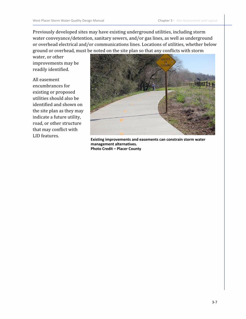
Previously developed sites may have existing underground utilities including storm
water conveyancedetention sanitary sewers andor gas lines as well as underground
or overhead electrical andor communications lines Locations of utilities whether below
ground or overhead must be noted on the site plan so that any conflicts with storm
water or other
improvements may be
readily identified
All easement
encumbrances for
existing or proposed
utilities should also be
identified and shown on
the site plan as they may
indicate a future utility
road or other structure
that may conflict with
LID features Existing improvements and easements can constrain storm water management alternatives Photo Credit ndash Placer County
3-7
Chapter 3 bull Site Assessment and Layout West Placer Storm Water Quality Design Manual
3-8
Chapter 4Site Planning and BMP Selection
Selection of an effective set of integrated storm water control measures or BMPs can be
challenging Each site is unique and the application of BMPs will vary depending on site
characteristics and proposed use of the site The storm water management requirements
vary depending on the different project categories (ie Small Regulated
Hydromodification Management Projects) This chapter provides a step-wise process for
selecting complementary BMPs to complete an effective and integrated design
This chapter is organized by project categories as described in Chapter 2 Information in
the corresponding subsection(s) below provides guidance for selection of BMPs that are
appropriate for the site and project type
41 Small Projects For Small Projects a site plan showing the layout of improvements and storm water
control measures is required to demonstrate consideration of the following
degdegdegdeg Define the development envelope and protected areas identifying areas that are
most suitable for development and areas to be landscaped or left undisturbed
and used for infiltration (Sections 311 through 314)
degdegdegdeg Minimize overall impervious coverage (paving and roofs) of the site
degdegdegdeg Set back development from creeks wetlands and riparian habitats in accordance
with local ordinances (Sections 312 and 313)
degdegdegdeg Preserve significant trees and native vegetation (Section 313)
degdegdegdeg Conform the site layout along natural landforms (Section 312)
degdegdegdeg Avoid excessive grading and disturbance of vegetation and soils and stabilize
disturbed areas
degdegdegdeg Replicate the sites natural drainage patterns (Section 312)
Implementation of one or more Site Design Measure listed in Table 4-1 is required to
reduce project site runoff The Site Design Measure(s) must be included on the site plan
and final improvement plans that are submitted with the building permit application
Note that some of the Site Design Measures for Small Projects are required to be designed
by an appropriately qualified professional engineer licensed in the State of California
4-1
Chapter 4 bull BMP Selection West Placer Storm Water Quality Design Manual
Fact Sheets in Appendix B provide detailed descriptions and design requirements for
each Site Design Measure listed
Additional guidance for incorporating the required storm water measures into Small Projects is provided in Chapter 6 and the SWQP Template in Appendix A
Table 4-1 Selection of Site Design Measures for Small Projects1
Small Projects must incorporate at least one Site
Design Measure Fact Sheet
(Appendix B) Selection Considerations
AdjacentOn-Site Stream Setbacks and Buffers SDM-1 Applicable for sites with streams on or
directly adjacent to the property
Soil Quality Improvement and Maintenance SDM-2
Consult a qualified professional before using in areas of high groundwater soil or groundwater contamination or slopes greater than 10 percent
Tree Planting and Preservation SDM-3 Irrigation requirements
Defensible space for wildfire
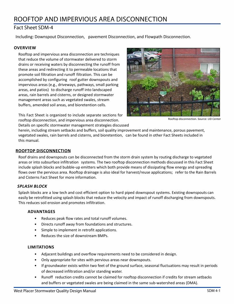
Rooftop and Impervious Area Disconnection SDM-4
Roof drain discharge must be at least six (6) feet from a basement and at leasttwo (2) feet from a crawl space orstructural foundation
Porous Pavement SDM-5
Consult a professional engineer before using in areas of high groundwater soil or groundwater contamination or slopes greater than 10 percent
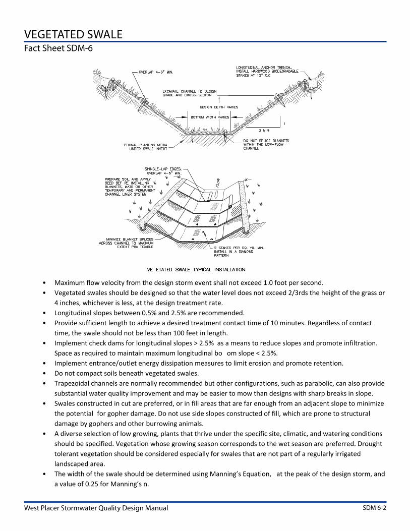
Vegetated Swales SDM-6
Consult a professional engineer before using in areas of high groundwater soil or groundwater contamination or slopes greater than 10 percent
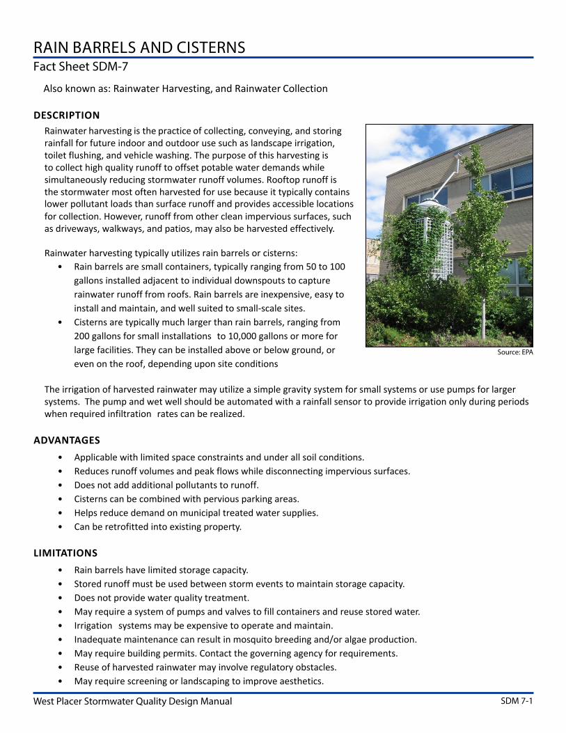
Rain Barrels and Cisterns SDM-7 Operation and Maintenance requirements
1 The Phase II MS4 Permit also allows the use of green roofs This Site Design Measurehas been omitted from this Manual as a practice that may not be suitable due to theclimate of the region and water conservation requirements However project applicantsmay propose green roofs as a Site Design Measure for consideration on a case-by-casebasis
42 Regulated Projects This section provides guidance for site design considerations and selection and layout of
storm water control measures for Regulated Projects The approach consists of applying
information from the site assessment to lay out improvements and BMPs to reduce storm
water runoff volumes and pollutant concentrations This information is intended as a
4-2
West Placer Storm Water Quality Design Manual Chapter 4 bull BMP Selection
reference source for the development of SWQPs for Regulated Projects which are
required to be completed by an appropriately qualified professional engineer licensed in
the State of California
Requirements for Regulated Projects include the following
deg Completing a site assessment to evaluate local conditions and identify LIDshyopportunities and constraintsshy
deg Developing a site layout that incorporates LID storm water management strategies
deg Implementing Site Design Measures to reduce surface runoff by infiltration
evapotranspiration andor harvesting and use as close to its source as possible
deg Implementing Storm Water Treatment and Baseline Hydromodification Measures
using bioretention-based facilities or facilities of demonstrated equivalent
effectiveness
deg Implementing biotreatmentmedia filters for special case exceptions toshybioretention or facility of demonstrated equivalent effectivenessshy
deg Implementing hydromodification management measures to control post-project
runoff rates (required for projects that create or replace more than one (1) acre of
impervious surface and result in a net increase in impervious area) and
deg Maintaining and implementing an OampM Plan
For maximum effectiveness the BMPs listed above should be designed to work together
in an integrated system BMPs can be designed in series to provide multiple treatment
steps for pollutant removal and volume reduction Pretreatment which refers to design
features that provide settling of large particles before storm water enters a storm water
treatment facility is important to ensure proper operation of the facility and reduce the
long-term maintenance burden Perhaps the most common example is a sediment trap
placed upstream of another BMP to remove bulk coarse solids in a location that is easily
accessed for maintenance upstream from a facility that provides further treatment and
runoff reduction By reducing sediment loads entering a bioretention facility or other
infiltration-based facility pretreatment protects the engineered planting media andor
underlying soil from being occluded prematurely and maintains the infiltration rate of
the facility Another example is installing an oilwater separator upstream of another
BMP to remove potential hazardous materials prior to infiltrating runoff The Phase II MS4 Permit requires that additional treatment steps be considered in high-risk areas
such as fueling stations truck stops auto repairs and heavy industrial sites to protect
groundwater quality
4-3
Chapter 4 bull BMP Selection West Placer Storm Water Quality Design Manual
The completed SWQP for Regulated Projects provides a multi-layered approach to
protect water quality and downstream water bodies The following sections describe the
site planning and BMP selection processes that must be used to develop an effective
integrated SWQP
421 Site Plan Layout
The results of the site assessment are used to develop the layout of improvements and
site plan which is submitted with the Preliminary SWQP (see Figure 4-1 for an example)
A list with the information required to be included on the site plan is provided in Chapter
6 under the Form 3-4 guidance The site plan together with the SWQP documents
consideration of the following items
degdegdegdeg Define the development envelope and protected areas identifying areas that are
most suitable for development and areas to be left undisturbed (Sections 312
through 314)
degdegdegdeg Concentrate development on portions of the site with less permeable soils and
preserve areas that can promote infiltration (Section 311)
degdegdegdeg Minimize overall impervious coverage (paving and roofs) of the site
degdegdegdeg Set back development from creeks wetlands and riparian habitats in accordance
with local ordinances (Sections 312 and 313)
degdegdegdeg Preserve significant trees (Section 313)
degdegdegdeg Conform the site layout along natural landforms (Section 312)
degdegdegdeg Avoid excessive grading and disturbance of vegetation and soils
degdegdegdeg Replicate the sites natural drainage patterns (Section 312)
degdegdegdeg Detain and retain runoff throughout the site
4211 Drainage Management Areas
As the proposed new or replaced impervious surfaces are laid out the associated
drainage management areas (DMAs) are defined and identified on the site plan DMAs are
the tributary areas within the project site that drain to a common location where BMPs
can be implemented to reduce and treat storm water runoff DMAs must be carefully
defined for each BMP that receive storm water runoff (from both pervious and
impervious surfaces) so that they may be appropriately designed Ideally DMAs are
defined and identified by separating areas that may drain pervious and impervious
surfaces However depending on the project site grading it may not be possible to
completely separate pervious and impervious surfaces when defining and identifying
DMAs If multiple types of surfaces are present in a DMA an appropriate composite storm
4-4
West Placer Storm Water Quality Design Manual Chapter 4 bull BMP Selection
water runoff coefficient must be used The placement of BMPs and identification of DMAs
is typically an iterative process as alternative layouts and storm water management
strategies are developed
As described previously LID storm water management strategy can involve
implementation of various BMP combinations in series Generally upstream BMPs or
Site Design Measures are smaller distributed measures that function to slow and reduce
runoff Downstream BMPs or Storm Water Treatment and Baseline Hydromodification
Measures function to remove pollutants from the remaining runoff and provide
additional runoff flow and volume control In some cases DMAs that discharge to
separate upstream BMPs must be combined for the design of BMPs located further
downstream in the sitersquos drainage system
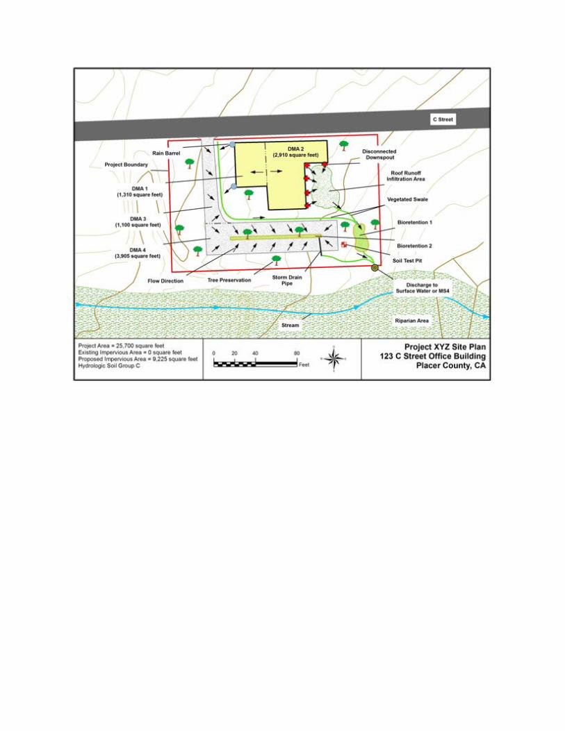
The site plan provided in Figure 4-1 presents an example of a new development project
consisting of an office building driveway and parking lot The site was separated into
four discrete DMAs DMA 1 consists of the western portion of the office building roof DMA 2 consists of the eastern portion of the office building roof DMA 3 consists of a
paved driveway and DMA 4 consists of a paved parking lot
Figure 4-1 Site Plan Example
4-5
Chapter 4 bull BMP Selection West Placer Storm Water Quality Design Manual
Site Design Measures and storm water treatmentbaseline hydromodification BMPs
(bioretention) to manage runoff from each DMA are also included in Figure 4-1 Roof
runoff from DMA 1 discharges to two rain barrels The rain barrels overflow to a
vegetated swale which discharges to a bioretention BMP during larger storm events Roof
downspouts from DMA 2 discharge away from the building to a natural depression where
infiltration occurs The natural depression area overflows into a vegetated swale which
conveys runoff to a bioretention BMP Driveway runoff from DMA 3 slopes towards a
vegetated swale which also conveys runoff to a bioretention BMP during larger storm
events In this example DMAs 1 2 and 3 all discharge to the same bioretention BMP
which would need to be designed to treat flows from all three DMAs Parking lot runoff from DMA 4 flows to a separate bioretention BMP (parking lot landscaped area) which
contains two existing trees to be preserved Treated storm water and overflow from both
bioretention BMPs is combined at a single discharge point and released offsite into the
municipal storm drain system or natural drainage way
422 Source Control Measures
After properly assessing a site and refining the layout source control measures are
implemented to reduce the potential for storm water runoff and pollutants from coming
into contact with one another The goal of source control measures is to KEEP CLEAN
WATER CLEAN
Source control measures can include both structural and operational measures
Structural source control measures include a physical or structural component for
controlling the pollutant source such as installing an efficient irrigation system to prevent
overspray and off-site runoff or covering trash enclosures or fuel dispensing operations
Operational source control measures involve practices such as storm water management
training trash management and litter control practices and general good housekeeping
practices When properly implemented source control measures are effective in
preventing pollutants from entering storm water runoff and are typically less expensive
than other types of storm water BMPs
Regulated Projects with potential pollutant-generating activities and sources are
required to implement applicable structural andor operational source control measures
Selection of source control measures must be based on an assessment of potential
pollutant generating activities or sources that are anticipated to occur at the site
Depending on the site operations and activities typical pollutants of concern that can be
mobilized and transported by storm water runoff may include but are not limited to
microbial pathogens (bacteria and viruses) metals nutrients toxic organic compounds
suspended solidssediment trash and debris and oil and grease Some examples of
source control measures include trash enclosures street or parking lot sweeping and
proper materials storage practices
4-6
West Placer Storm Water Quality Design Manual Chapter 4 bull BMP Selection
In some areas downstream water bodies may be impaired or subject to TMDL
requirements (Chapter 3) In these situations the pollutant(s) of concern must be
identified along with any additional actions that may be required to control potential
releases of the pollutant(s)
The Source Control Measures Selection Table (Appendix C) shall be used as a guideline to
identify and select source control measures for inclusion in the SWQP In some cases
multiple source control measures will be used in combination The table does not include
all possible pollutant generating project characteristicsactivities that may warrant the
consideration of source control measures and additional operational or structural source
control measures may be required
The California Stormwater Quality Association (CASQA) Storm Water BMP Handbooks or
an accepted equivalent reference document provide recommended guidance for design
of source control measures CASQA has published several storm water BMP handbooks
for various project applications and settings and the source control measures identified
in Appendix C reference fact sheets in one or more of these handbooks The identification
codes in the table correspond to the CASQA fact sheets which can be referenced for more
information on each source control measure The CASQA Storm Water BMP Handbooks
are available for purchase at
wwwcasqaorgresourcesbmp-handbooks
4-7
Chapter 4 bull BMP Selection West Placer Storm Water Quality Design Manual
423 Site Design Measures (LID BMP Selection)
Site Design Measures are generally small-scale
distributed BMPs that are intended to reduce and
treat surface runoff volumes by managing storm
water as close to its source as possible Site
Design Measures often incorporate vegetation
which can further reduce runoff through
evapotranspiration These storm water controls
are critical for maintaining a sitersquos
predevelopment hydrology which is a primary
goal of LID
Regulated Projects are required to incorporate
the Site Design Measures listed in Table 4-3 to
the extent technically feasible with the objective
of retaining the impervious runoff volume
generated by the post-construction 85th
percentile 24-hour storm event by means of
infiltration evapotranspiration andor
harvesting and use Typical feasibility
considerations are included in the table but
technical feasibility can vary based on a wide variety of site specific conditions that must
be evaluated and determined by a professional engineer Technical feasibility also
requires approval by the jurisdictional agency
If Site Design Measures applied are demonstrated to completely treat and retain the
impervious runoff from the post-construction 85th percentile 24-hour storm event then
no additional downstream BMPs are required This determination is made during the
development of the SWQP (Appendix A) The Site Design Measure Fact Sheets (Appendix
B) provide detailed descriptions and design requirements for each measure listed inTable 4-2
Distributed Site Design Measures such as this cistern can provide significant reductions in site runoff Photo Credit ndash US EPA
4-8
West Placer Storm Water Quality Design Manual Chapter 4 bull BMP Selection
Table 4-2 Selection of Site Design Measures for Regulated Projects1
Regulated Projects must incorporate Site Design Measures to the Extent Technically Feasible
Fact Sheet
(Appendix B) Feasibility Considerations
Stream Setbacks and Buffers SDM-1 deg Applicable for sites with streams
on or directly adjacent to the property
Soil Quality Improvement and Maintenance SDM-2
deg Not suitable in areas of high groundwater soil or groundwater contamination or slopes greater than 10 percent
Tree Planting and Preservation SDM-3 deg Irrigation requirements deg Defensible space for wildfire
Rooftop and Impervious Area Disconnection SDM-4
deg Roof drain discharge must be at least six (6) feet from a basement and at least two (2) feet from a crawl space or structural foundation
Porous Pavement SDM-5
deg Not suitable in areas of high groundwater soil or groundwater contamination or slopes greater than 10 percent
deg Not ideal for sites with infiltration rates less than 05 inhr
deg Not suitable in areas with heavy equipment or traffic loads
deg Sediment deposition will cause clogging
Vegetated Swales SDM-6
deg Not suitable in areas of high groundwater soil or groundwater contamination or slopes greater than 10 percent
Rain Barrels and Cisterns SDM-7 deg Must be emptied to re-establish
storage volume between storm events
1 The Phase II MS4 Permit also allows the use of green roofs This Site Design Measure has been omittedfrom this Manual as a practice that may not be suitable due to the climate of the region and waterconservation requirements However project applicants may propose green roofs as a Site DesignMeasure which will be evaluated on a case-by-case basis
4-9
Chapter 4 bull BMP Selection West Placer Storm Water Quality Design Manual
424 Storm Water Treatment and Baseline Hydromodification Management
After implementation of
Site Design Measures
remaining runoff that is
not retained by the Site
Design Measures must be
directed to storm water
treatmentbaseline
hydromodification
facilities sized to manage
the remaining portion of
the post-construction 85th Bioretention can be integrated into a sitersquos landscaping to
percentile 24-hour storm provide water quality and aesthetic benefits while also reducing project costs event runoff These Photo Credit ndash Greg Bates
treatment facilities also
known as bioretention facilities are designed to infiltrate evapotranspire andor
bioretain the remaining storm water similar to the LID principles of the Site Design
Measures Depending on site characteristics infiltrating or non-infiltrating flow-through
bioretention facilities are typically used to meet this requirement Infiltrating systems are
preferred and the use of flow-through systems with impervious liners to prevent
infiltration is only permitted in several specific cases These specific circumstances
include shallow groundwater conditions the existence of underlying groundwater or soil contamination when infiltration creates the potential for geotechnical hazards or when
the facility is located on an elevated plaza or other structure Bioretention facilities
provide pollutant removal through several mechanisms including sedimentation
filtration and biological processes Additionally they reduce runoff volumes and peak
flow rates to mitigate the potential hydromodification effects of development
The determination of which type of storm water treatmentbaseline hydromodification
control measure(s) to implement can be made using the following flow chart in Figure 4-2 As shown infiltrating bioretention BMPs are required in the majority of cases Once theappropriate storm water treatment BMP(s) is (are) selected refer to the correspondingFact Sheet (Appendix B) for further design considerations and allowable variations
4-10
West Placer Storm Water Quality Design Manual Chapter 4 bull BMP Selection
Figure 4-2 Selection of Storm Water TreatmentBaseline Hydromodification Controls
Alternative storm water treatment and baseline hydromodification facilities may be
proposed by the designer if the designer can demonstrate that the proposed facility
meets all of the following measures of equivalent effectiveness criteria when compared to
bioretention facilities
degdegdegdeg Equal or greater amount of storm water runoff infiltrated or evapotranspired for
alternatives to infiltrating bioretention facilities
degdegdegdeg Equal or greater rate of storm water treatment for flow-through facilities
4-11
Chapter 4 bull BMP Selection West Placer Storm Water Quality Design Manual
degdegdegdeg Equal or lower pollutant concentrations in storm water runoff that is discharged
after biotreatment
degdegdegdeg Equal or greater protection against shock loadings and spills
degdegdegdeg Equal or greater accessibility and ease of inspection and maintenance
Proposed alternative storm water treatment and baseline hydromodification facilities will be reviewed on a case-by-case basis by the jurisdictional agency
43 Hydromodification Management Projects The term ldquohydromodificationrdquo is used to define the changes that occur to the natural
hydrologic systems of streams and watersheds and how they have the potential to
disrupt the natural balances within the watershed Hydromodification resulting from
land development has the potential to create impacts such as excessive erosion sediment
transport and deposition stream bed instability loss of habitat pollutant loading and
damage to the overall ecosystem in downstream reaches of watershed systems The
dynamics of development projects have historically decreased groundwater recharge
increased runoff volume and peak flow frequencies and altered the natural hydraulic
loading of the receiving water (creek system) hydrology Most LID principles
incorporated into this Manual begin to address and minimize these impacts In the event
that storm water runoff reductions do not meet post-construction condition
requirements as demonstrated with the runoff reduction calculator (made part of the
Storm Water Template ndash Appendix A) additional hydromodification treatment measures
are required for Regulated Projects creating andor replacing one acre or more of
impervious surface that create a net increase in impervious surface
The required performance standard for hydromodification control consists of
maintaining post-project runoff at or below pre-project flow rates for the 2-year 24-hour
storm event If this standard can be achieved through the implementation of Site Design
Measures and storm water treatmentbaseline hydromodification controls (as
referenced in Section 42 above) then no further storm water controls are required If post-construction peak flows do not meet this standard then additional storage capacity
with flow control at the discharge point must be incorporated into the design
For hydromodification management projects in sensitive environmental locations
andor larger sized projects with complex hydrologic characteristics the jurisdictional
agency may require an alternative approach to using the template forms In these cases
additional hydrologic modeling analyses such as a HEC-1 or HEC-HMS discrete storm
analysis may be required to compare pre- and post-project discharge rates for
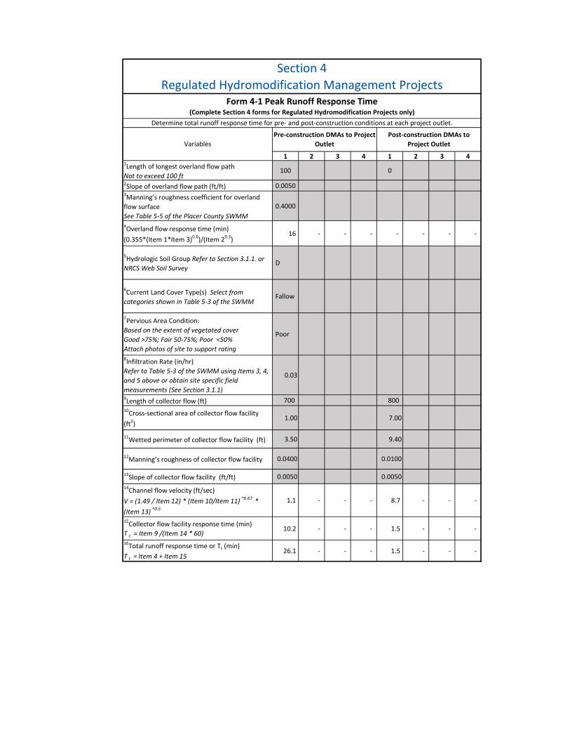
compliance In these cases the Section 4 form should be replaced with model results
documentation showing that post-construction runoff is less than or equal to the pre-construction runoff rate for a 2-year 24-hour storm event
4-12
West Placer Storm Water Quality Design Manual Chapter 4 bull BMP Selection
BMP selection for hydromodification controls should be based on the amount of
additional storage needed Additional storage capacity for hydromodification
management can be provided by either increasing the size of the control measures (eg Site Design Measures or storm water treatment and baseline hydromodification facilities)
that are already incorporated in the design or by adding separate structures such as
detention basins or vaults
Follow the procedures outlined in Chapter 6 and the SWQP Template to determine the
additional storage volume needs to select the preferred alternative If relatively little
additional storage is needed then increasing the capacity of the Site Design andor storm
water treatment measures is likely to be the preferred alternative For larger additional
storage requirements separate detention facilities are recommended
44 In Lieu Program Storm water management requirements must be met to the MEP standard as specified in
this Manual and within and on the project site If the storm water management goals
specified in this Manual cannot be fully met on the project site due to feasibility
constraints then an In Lieu Project may be identified to satisfy the remaining
requirements All projects that utilize the In Lieu program require review and approval
by the CVRWQCB in addition to the jurisdictional agency
The In Lieu program provides two options
Option 1- In Lieu Projects
A separate LID or other environmental protectionenhancement project may be selected
from the list of pre-approved projects developed by the jurisdictional agency and
approved by the CVRWQCB If an In Lieu Project option is chosen the jurisdictional
agency will identify the In Lieu Project in the Conditions of Approvals to ensure that the
requirement is documented in case the property andor project is sold The pre-approved list of In Lieu Projects may be amended periodically on a case-by-case basis
with approval from both the CVRWQCB and jurisdictional agency
In Lieu Projects should treat the same type of pollutants that are generated by the
untreated portion of the new development or redevelopment project For example if the
untreated portion of the new development or redevelopment site is roadway then the In
Lieu Project selected should treat runoff from a roadway
In Lieu Projects should be located within the same jurisdiction or unincorporated area in
which the new development or redevelopment project causing the impact is located
Projects located in other areas may be approved on a case-by-case basis Projects that
have the potential to cause a significant impact to a particular water body as determined
4-13
Chapter 4 bull BMP Selection West Placer Storm Water Quality Design Manual
by the jurisdictional agency either because of the size of the project or the sensitivity of
the water body will need to choose an In Lieu Project in the same watershed if feasible
In Lieu Projects must be completed within two years of the completion of the qualifying
new development or redevelopment project If additional time is needed to complete the
In Lieu Project an extension may be requested and approved on a case-by-case basis To
compensate for long-term water quality and hydromodification impacts downstream of
the project penalties in the form of additional fees or additional treatment areas may be
imposed on projects requiring time extensions by the jurisdictional agency
Option 2 - In Lieu Fee
An In Lieu Fee may be paid toward the completion of a larger project from the pre-approved list The amount of the In Lieu Fee will be calculated based on the treatment
andor volume capture not achieved on the project site including maintenance costs
times a multiplier
4-14
Chapter 5BMP Inspection Operation and Maintenance
Structural BMPs required for Regulated Projects must meet manufacturersrsquo or designerrsquos
recommendation for operation and maintenance to ensure that the facilities are
functioning as designed and do not create health and safety hazards
To support these requirements owners of Regulated Projects must provide specific
operations and maintenance (OampM) related information with the SWQP during the
project permitting process and submit annual self-certification reports documenting that
the OampM activities are performed and BMPs are functioning properly
51 Operation and Maintenance Submittal Requirements at the Permitting Stage The following items are required to be included in the SWQP for all Regulated Projects
degdegdegdeg A signed statement from the project owner accepting responsibility for
inspection and OampM activities for all structural BMPs at the project site until such
responsibility is legally transferred to another entity
degdegdegdeg A signed statement from the project owner granting access to all representatives
of the jurisdictional agency for the sole purpose of performing OampM inspections
of the installed treatment systems(s) and hydromodification control(s) if any
Alternatively this requirement is considered satisfied if an easement dedication
or irrevocable offer of dedication is made to the jurisdictional agency providing
equivalent access
degdegdegdeg A list of all structural BMPs on the project site and their specific inspection and
OampM requirements BMP-specific inspection and OampM requirements are included
on the respective Fact Sheets (Appendix B) It is the responsibility of the project
owner to review these requirements and develop a detailed site-specific OampM
Plan to document these requirements and include it with the SWQP
degdegdegdeg A copy of any maintenance agreements that modify the BMP OampM responsibilities
for the project
52 Annual Self-Certification Reports In addition to the above items which are required at the permitting phase Annual Self-Certification Reports must be submitted by the responsible party for the life of the
project In accordance with the Phase II MS4 Permit the Annual Self-Certification Reports
must include at a minimum the following information
5-1
Chapter 5 bull BMP Inspection Operation and Maintenance West Placer Storm Water Quality Design Manual
degdegdegdeg Dates and findings of field observations to determine the effectiveness of the
structural BMPs in removing pollutants of concern from storm water runoff andor reducing hydromodification impacts as designed
degdegdegdeg Long-term plan for conducting regular maintenance of BMPs including the
frequency of such maintenance
5-2
Chapter 6
Developing a Post-Construction Storm Water
Quality Plan (SWQP)
This chapter in conjunction with the SWQP Template in Appendix A provides project
applicants project owners and design professionals with supplemental guidance for
developing a SWQP for the various project categories defined herein
The SWQP Template also provides planning and design review staff with a standardized
submittal format to streamline the project review and approval process In some cases if the applicant wishes to propose alternative storm water control measures supplemental
documentation is required to be submitted to demonstrate equivalent performance per
the listed criteria
The SWQP for Regulated Projects must outline project compliance with the requirements
of this Manual and include a signed certification statement by a registered professional
engineer and project owner accepting responsibility for its development and
implementation SWQPs for Small Projects do not require a professional engineerrsquos
certification however some storm water control measures may require engineered
designs A copy of the Final SWQP shall be available at the project site for the duration of
construction and then stored with the project approval documentation and improvement
plans in perpetuity
The SWQP development process begins with identifying the Project Category (see
Chapter 2) and completing the corresponding sections in the SWQP template Table 6-1
below lists the sections in the SWQP that must be completed for each Project Category
Table 6-1 Required SWQP Sections by Project Category
Project Category Required SWQP Sections
Small Projects Sections 1 and 2 Regulated Projects Regulated Redevelopment Projects Regulated Road Projects and Regulated LUPs
Sections 1 3 5 and 6
Regulated Hydromodification Management Projects Sections 1 3 through 6
6-1
Chapter 6 bull Developing a Post-Construction Storm Water Quality Plan (SWQP) West Placer Storm Water Quality Design Manual
For Small Projects the project owner may prepare the SWQP If the SWQP is prepared bythe project owner then the project owner takes the responsibility for ensuring theproper design of any storm water control measures that are included in the project ForRegulated Projects a California licensed professional engineer is required to preparesign and stamp the SWQP Storm water control measures described in this Manual mustbe designed by or under the supervision of a qualified California licensed ProfessionalEngineer with other specialist as may be needed
Using the SWQP Template (Appendix A)
The SWQP Template is an automated Microsoft Excel-based tool that is provided inelectronic format The user proceeds through a series of pages by opening the workbooktabs which are labeled to indicate which form they contain Required information isentered in the shaded gray cells while other cells will self-populate to complete the formEach section below provides supporting information and guidance on completing theassociated forms in the SWQP Template Other more detailed reference information isprovided in the preceding Chapters of this manual and in the BMP fact sheets in AppendixB
Title Page
The title page identifies the project project owner and individual or consulting firmresponsible for the preparation of the SWQP It also lists the jurisdictional agency withapproval authority for the project and responsibility for implementing the requirementsof the Phase II MS4 Permit
Project identification information such as Building or Grading Permit Numbers may varyamong the jurisdictional agencies and should be included as appropriate for the specificproject
The SWQP preparation date is added by the preparer and the approval date is added bythe approving jurisdictional agency to the cover as they become available
Section 1 General Project Information
Section 1 documents basic information pertaining to the project and identifies theindividual(s) responsible for the development and implementation of the SWQP TheProject Category is identified here
There are two forms to be completed in Section 1 as follows
Form 1-1 Project Identification and Ownerrsquos Certification
Form 1-1 supplements information provided on the title page with additional detailincluding the project address and a brief description of the project For larger or morecomplex projects sheets may be added to describe the project
6-2
Chapter 6 bull Developing a Post-Construction Storm West Placer Storm Water Quality Design Manual Water Quality Plan (SWQP)
The project ownerrsquos signature is required to certify responsibility for properimplementation of the SWQP For Regulated Projects the project owner signature alsoprovides permission to access to all representatives of the jurisdictional agency for thesole purpose of performing OampM inspections of the installed treatment system(s) andhydromodification control(s) if any
For Regulated Projects a California licensed professional civil engineer is required to signand stamp the SWQP The professional engineer is responsible for designing all of thestorm water control measures for the project site and developing the SWQP per therequirements set forth in the Phase II MS4 Permit and this Manual
Form 1-2 Project Category
Form 1-2 identifies the project category Determine the appropriate category by firstquantifying the size of the newly created andor replaced impervious surface and usingthe decision tree in Figure 2-3 Once the project category is determined check theappropriate box on the form
For redevelopment projects determine the percent increase of impervious surface andcheck the appropriate box The percent increase calculation must include both newlycreated and replaced surfaces
Use the form to indicate if the project is a road or linear undergroundoverhead project(LUP) that creates 5000 ft2 or more of newly constructed contiguous impervious surfaceor is a public road project andor falls under the building and planning authority of ajurisdictional agency
After determining and checking the appropriate project category enter the total newandor replaced impervious surface area for the project
Section 2 Requirements for Small Projects
Owners of Small Projects are required to complete the forms in Section 1 and 2 of theSWQP Template The forms in Section 2 guide the development of the project layout asdiscussed in Chapter 4 and incorporate one or more of the Site Design Measures listed inTable 4-1 Section 2 includes two forms to address these requirements
Form 2-1 LID Site Assessment and Layout Documentation
The goal of the site assessment is to develop the site in a way that minimizes impacts tothe site hydrology and other environmental functions and processes The form lists aseries of considerations that should be made when developing the layout For each itemcheck the appropriate box to indicate that it has been considered and appropriatelyincorporated or that it is not applicable (NA) and provide a brief explanation (use aseparate sheet if necessary) To complete this form develop and attach the site plan thatillustrates the proposed site layout The site plan may consist of a preliminary or
6-3
Chapter 6 bull Developing a Post-Construction Storm Water Quality Plan (SWQP) West Placer Storm Water Quality Design Manual
conceptual level design drawing and it is a key requirement of the Preliminary SWQPdescribed in Section 2
Ensure that the following items at a minimum are included in the site plan
degdegdegdeg Site boundary
degdegdegdeg Topographic data with one-foot contours ( five foot contour intervals may beused for steeper sites)
degdegdegdeg Existing natural hydrologic features (eg depressions watercourses wetlandsriparian corridors)
degdegdegdeg Environmentally-sensitive areas and areas to be preserved
degdegdegdeg Proposed locations and footprints of improvements creating new or replacedimpervious surfaces
degdegdegdeg Proposed site drainage with flow directions and site run-on and dischargelocations
degdegdegdeg Proposed Site Design Measures to reduce runoff
Form 2-2 Runoff Reduction Calculator Site Design Measures on Small Projects
This form is used to identify one or more Site Design Measures to implement on SmallProjects and calculate the associated storm water runoff reduction After identifying theSite Design Measure(s) enter the associated dimensions and quantity information intothe form to calculate the storm water runoff reduction and effective treated imperviousarea There is no minimum runoff reduction required for Small Projects Design guidancefor Site Design Measures is provided in the Fact Sheets in Appendix B The equationsvariables and units that are used to calculate the Site Design Measure volume reductions(Vr) are presented below for reference
AdjacentOn-Site Stream Setbacks and Buffers
Aimp (ft2) - Impervious drainage area discharging to the bufferV85 (in) ndash Runoff volume from the 85th percentile 24-hour design storm
6-4
Vr = (1 119891119905
12 119894119899) timesA119894119898119901timesV85
Chapter 6 bull Developing a Post-Construction Storm West Placer Storm Water Quality Design Manual Water Quality Plan (SWQP)
Soil Quality Improvement and Maintenance
Apond (ft2) ndash Ponding area over soil improvement areaDpond (ft) ndash Ponding depth over soil improvement areaAsa (ft2) ndash Surface area of improved soilsDsa (ft) ndash Depth or thickness of improved soil layerη - Porosity of amended soil
Tree Planting and Preservation
ne ndash Number of new evergreen treesnd ndash Number of new deciduous treesAtc (ft2) ndash Atc (ft2) ndash Canopy area of existing trees to remain on the propertyV85 (in) ndash Runoff volume from the 85th percentile 24-hour design storm
Rooftop and Impervious Area Disconnection
Porous Pavement
Vegetated Swales
Aimp (ft2) - Impervious rooftop or other area draining to swaleV85 (in) ndash Runoff volume from the 85th percentile 24-hour design storm
6-5
1 119891119905
12 119894119899Vr= [(218timesne) + (109timesnd) + Atc] lowast V85 lowast ( )
Vr = (A119901119900119899119889timesD119901119900119899119889) + (AsatimesD119904119886times ɳ)
Aimp (ft2) - Impervious rooftop or other area draining to perviousinfiltration area
V85 (in) ndash Runoff volume from the 85th percentile 24-hour design storm
Vr = A119903119890s timesD119903119890s timesɳ gg timesC
Ares (ft2) ndash Area of underlying gravel storage layer
Dres (ft) ndash Depth of underlying gravel storage layer
ηagg ndash Porosity of aggregate
C ndash Efficiency factor (See table in Fact Sheet SDM-5)
Vr = (1 119891119905
12 119894119899) timesA119894119898119901timesV85
1 119891119905119903 = (
12 119894Ā) times119860119894119898119901timesV85 V
bull
Rain Barrels and Cisterns
= 05 times times
- Number of rain barrels andor cisterns) - Volume of each rain barrel andor cistern
Form 2-2 includes storm water runoff reduction calculations that are equivalent to those in the SWRCBrsquos SMARTS Runoff Reduction Calculator The volume reductions calculated by these methods are dependent on the Site Design Measure(s) being designed per the requirements in the respective Fact Sheets in Appendix B
In order to calculate runoff reductions Form 2-2 requires the project elevation which is inserted at the top of the form The form then calculates the impervious runoff volume generated by the design storm A table is included as a footnote to the form showing the design storm depths that correspond to the elevation of the project Corresponding runoff volumes are calculated using a runoff coefficient of 09 for impervious surfaces
This section addresses the requirements for Regulated Projects The forms in this section are used to document project characteristics and to facilitate the selection and design of storm water control measures Projects in this category are required to implement the following storm water control measures to the maximum extent practicable
LID site assessment to appropriately plan the layout of improvements for capturing and retaining storm water runoff
Source control measures to mitigate potential pollutant generating activities and sources that are anticipated at the site
Site Design Measures to infiltrate evapotranspire andor harvest and use the impervious runoff from the post-construction 85th percentile 24-hour storm runoff event and
Storm Water Treatment and Baseline Hydromodification Measures to infiltrate evapotranspire andor bioretain remaining runoff from impervious surfaces if necessary after implementation of Site Design Measures
Section 3 contains seven forms to address each of the above requirements
Chapter 6 Developing a Post-Construction Storm West Placer Storm Water Quality Design Manual Water Quality Plan (SWQP)
6-7
Form 3-1 Site Location and Hydrologic Features
Enter the project specific information to document the site location and elevation to
calculate the 85th percentile 24-hour design storm depth For reference the table below
provides the 85th percentile 24-hour design storm depths for three elevation increments
within the West Placer region
85th Percentile 24-Hour Design Storm Depth Elevation lt500 feet = 09 inch
Elevation 500-1000 feet = 10 inch Elevation 1000-1500 feet = 11 inch
Identify the ultimate receiving waters and provide a general description of their location
and distance in relation to the project site
If the receiving waters are listed as impaired on the state 303(d) list identify the
pollutant(s) of concern Refer to SWRCB website for the most current information
wwwwaterboardscagovwater_issuesprogramswater_quality_assessmentimpaired
For phased projects the form clarifies requirements for defining DMAs and incorporating
storm water control measures as each phase is developed
This form is also used to define the projectrsquos DMAs as described in Chapter 4 For
projects with more than one DMA a conceptual level schematic should be developed
showing the DMAs that have been defined for the project and their hydrologic
connections to the site discharge location(s) The conceptual DMA diagram in this form
should be referenced when laying out DMAs and conveyances in the projectrsquos site plan as
required in Form 3-2
Form 3-2 LID Site Assessment and Layout Documentation
A site assessment must be conducted as early as possible in the project planning process
to appropriately plan the site layout for the capture and treatment of storm water runoff
The goal is to develop a site layout that minimizes impacts to site hydrology and other
environmental systems functions and processes
The form lists a series of considerations that should be evaluated when developing the
site layout For each item check the appropriate box to indicate that it has been
considered and appropriately incorporated or that it is not applicable (NA) and provide
a brief explanation (use a separate sheet if necessary) To complete this form develop
and attach a site plan that illustrates the proposed site layout The site plan may consist
of a preliminary or conceptual level design drawing but it is a key requirement of the
Preliminary SWQP described in Section 2
Chapter 6 Developing a Post-Construction Storm Water Quality Plan (SWQP) West Placer Storm Water Quality Design Manual
6-8
Ensure that the following items are included in the site plan
Site boundary
Soil types and areal extents test pit and infiltration test locations
Topographic data with 1-foot contours ( 5-foot contour intervals may be used for
steeper sites)
Existing natural hydrologic features (eg depressions watercourses wetlands
riparian corridors)
Environmentally-sensitive areas and areas to be preserved
Proposed locations and footprints of improvements creating new or replaced
impervious surfaces
Potential pollutant sources areas
DMAs for the proposed BMPs that will receive storm water runoff
Existing and proposed site drainage network with flow directions and site run-on
and discharge locations
Proposed design features and surface treatments used to minimize
imperviousness and reduce runoff
Proposed locations and footprints of treatment and hydromodification
management facilities
Design features for managing authorized non-storm water discharges
Areas of soil andor groundwater contamination
Existing utilities and easements
Maintenance areas
Form 3-3 Source Control Measures
Source control measures are required on all Regulated Projects to prevent onsite
pollutants from being mobilized and transported by storm water runoff The goal of
source control is to keep clean water clean For each item listed in the form check the box
for activities and sources that may occur on the project and use the Source Control
Measures Selection Table (Appendix C) to identify permanent structural andor
operational source control measures Add project specific descriptions of how each
measure will be implemented on the project and attach additional pages if necessary Be
sure to describe any special features materials or methods of construction that will be
used to implement the source control measures The identification codes in the table
correspond to the CASQA fact sheets which can be referenced for more information on
each source control measure The CASQA Storm Water BMP Handbooks are available for
purchase at
Chapter 6 bull Developing a Post-Construction Storm West Placer Storm Water Quality Design Manual Water Quality Plan (SWQP)
wwwcasqaorgresourcesbmp-handbooks
Form 3-4 Runoff Reduction Calculator for Site Design Measures on Regulated Projects
On Regulated Projects Site Design Measures must be implemented to the extenttechnically feasible to infiltrate evapotranspire andor harvest and use the impervioussurface runoff from the post-construction 85th percentile 24-hour storm event
For each DMA identify the Site Design Measure(s) for implementation and enter theassociated dimensions and quantity information into the form to calculate the resultingrunoff reduction and the effective treated impervious area Design guidance for SiteDesign Measures in provided in the Fact Sheets in Appendix B The equations variablesand units that are used to calculate the Site Design Measure volume reductions (Vr) arepresented below for reference
AdjacentOn-Site Stream Setbacks and Buffers
Aimp (ft2) - Impervious drainage area discharging to the bufferV85 (in) ndash Runoff volume from the 85th percentile 24-hour design storm
Soil Quality Improvement and Maintenance
Vr =
Apond (ft2) ndash Ponding area over soil improvement areaDpond (ft) ndash Ponding depth over soil improvement areaAsa (ft2) ndash Surface area of improved soilsDsa (ft) ndash Depth or thickness of improved soil layerη - Porosity of amended soil
Tree Planting and Preservation
ne ndash Number of new evergreen treesnd ndash Number of new deciduous treesAtc (ft2) ndash Canopy area of existing trees to remain on the propertyV85 (in) ndash Runoff volume from the 85th percentile 24-hour design storm
6-9
1 ft
12 in_____( ) x Aimp x V85
Vr = (Apond x Dpond) + (Asa x Dsa x ɳ
Vr = [(218xne) + (109xnd)+Atc] V85 ) ( 1 ft
12 in___
Chapter 6 Developing a Post-Construction Storm Water Quality Plan (SWQP) West Placer Storm Water Quality Design Manual
6-10
Rooftop and Impervious Area Disconnection
119881119903 = (1 119891119905
12 119894119899) times 119860119894119898119901 times 11988185
Aimp (ft2) - Impervious rooftop or other area draining to pervious
infiltration area
V85 (in) ndash Runoff volume from the 85th percentile 24-hour design storm
Porous Pavement
119881119903 = 119860119903119890119904 times 119863119903119890119904 times 120578119886119892119892 times 119862
Ares (ft2) ndash Area of underlying gravel storage layer
Dres (ft) ndash Depth of underlying gravel storage layer
ηagg ndash Porosity of aggregate
C ndash Efficiency factor (05 recommended)
Vegetated Swales
119881119903 = (1 119891119905
12 119894119899) times 119860119894119898119901 times 11988185
Aimp (ft2) - Impervious rooftop or other area draining to swale
V85 (in) ndash Runoff volume from the 85th percentile 24-hour design storm
Rain Barrels and Cisterns
119881119903 = 05 times 119873 times 119881119886
N - Number of rain barrels andor cisterns
Va (ft3) - Volume of each rain barrel andor cistern
Form 3-4 includes runoff reduction calculations that are equivalent to those in the
SWRCBrsquos SMARTS Runoff Reduction Calculator The volume reductions calculated by
these methods are dependent on the Site Design Measure(s) being designed per the
requirements in the respective Fact Sheets in Appendix B
Form 3-4 calculates the impervious runoff volume generated by the design storm using a
runoff coefficient of 09 for impervious surfaces
The form calculates the effective treated impervious area by dividing the runoff reduction
by the depth of runoff produced by the 85th percentile 24-hour design storm depth
If the post-construction 85th percentile 24-hour storm event runoff from all impervious
surfaces in a DMA is treated no additional storm water control measures are required for
that DMA If there is untreated impervious area remaining then Storm Water Treatment
and Baseline Hydromodification Measures are required
Chapter 6 Developing a Post-Construction Storm West Placer Storm Water Quality Design Manual Water Quality Plan (SWQP)
6-11
Form 3-5 Computation of Water Quality Design Criteria for Storm Water Treatment and Baseline Hydromodification Measures
After implementation of Site Design Measures any remaining storm water runoff for each
DMA must be directed to one or more facilities designed to infiltrate evapotranspire
andor bioretain these remaining storm water flows This form calculates the target
Water Quality Volumes and Flows (WQV and WQF respectively) using the tributary
drainage area sizes and characteristics and local rainfall statistics If all impervious area
requiring treatment is treated by Site Design Measures this form will return a zero value
for WQV and WQF as no additional downstream BMPs are required The Unit WQV
referenced in the form is based on the site elevation and a 48 hr drawdown time as
follows
Project Elevation (ft above mean sea level)
Unit Water Quality Volume (WQV)
(inches) Over 1000 ft 09
500 ft ndash 1000 ft 075 Under 500 ft 065
Storm water runoff entering a site from adjacent properties (run-on) becomes the
responsibility of the owner When entering the DMA sizes in this form all offsite areas
that may contribute run-on flows to the treatment facility must be included
For DMAs containing multiple types of land cover the form requires the user to enter a
composite area-weighted runoff coefficient representing the DMA The composite runoff
coefficient can be calculated as
CW = weighted runoff coefficient Cj = runoff coefficient for area j Aj (ft2) = area for land cover j n = number of distinct land covers
The equations variables and units that are used to calculate the WQV and WQF are
presented below for reference
Chapter 6 Developing a Post-Construction Storm Water Quality Plan (SWQP) West Placer Storm Water Quality Design Manual
6-12
Water Quality Volume (WQV)
119882119876119881 (1198911199053) = (1 119891119905
12 119894119899) times 119860 times 119877119888 times 119882119876119881119906
A (ft2) ndash Tributary Area to BMP
Rc ndash Runoff coefficient
WQVU (in) - Unit Water Quality Volume
Water Quality Flow (WQF)
119882119876119865(1198911199053119904) = (1 119891119905
12 119894119899) times (
1 ℎ119903
3600 119904) times 119860 times 119894119906 times 119877119888
WQF (ft3s) = Auntreated Iu (1ft12in) (1hr3600s)
A (ft2) ndash Tributary Area to BMP
iu (inhr) ndash Uniform Rainfall Intensity = 02 inhr
Rc ndash Runoff coefficient
Form 3-6 Infiltrating Bioretention Measures
Form 3-6 is a sizing tool for volume-based infiltrating bioretention facilities Enter the
dimensions and other required design parameters for each bioretention facility to
calculate volume reductions and determine if the required performance criteria have
been achieved The form is intended to be used in conjunction with the bioretention BMP
Fact Sheet(s) in Appendix B which provide additional design guidance
The following inputs must be determined by the designer and entered into the
appropriate cells
DMA ID No ndash Previously defined DMAs for the Site Design Measures should be
combined if they are draining to a single bioretention measure Enter a unique
identifier for the combined DMAs
Water Quality Volume (WQV) ndash If multiple DMAs are combined as described
above the WQVs for each DMA must be summed
Surface Loading Rate (Rsurf)(inhr)
BMP Surface Area (top of BMP)(SAtop) (ft2)
Infiltration rate of soils underlying the BMP (use field measurement at the level
where infiltration will occur)(inhr)
Maximum ponding depth (dmax) (ft)
Infiltrating surface area (bottom of BMP) (SAbottom) (ft2)
Chapter 6 Developing a Post-Construction Storm West Placer Storm Water Quality Design Manual Water Quality Plan (SWQP)
6-13
Planting media depth (dmedia) (ft)
Planting media porosity (nmedia)
Gravel depth (dgravel) (ft)
Gravel porosity (ηgravel)
Total Treated Flow Rate for Project (Qtotal)(ft3s) ndash Enter the total sum of all
treated flows from all DMAs
Calculated values in Form 3-6 include the following
Ponding depth (dpond) (ft) ndash This is determined by comparing the depth of water infiltrated within the drawdown time and the maximum ponding depth The lesser value is taken as the ponding depth
Retention Volume (Vd) (ft3) ndash This is the total runoff volume reduction achieved by the
bioretention measure Retention volume is calculated as follows
119881119903 = 119878119860119887119900119905119905119900119898 times [119889119901119900119899119889 + 119889119898119890119889119894119886 times 120578119898119890119889119894119886 + 119889119892119903119886119907119890119897 times 120578119892119903119886119907119890119897 + (1 119891119905
12 119894119899) times 119879119891 times 119868 119883 05]
The time of filling (Tf) represents the amount of time typically required for the bioretention
measure to fill after the initial onset of rain A value of 3 hours is assumed and is incorporated
into the calculation
A safety factor of 05 is applied to the field measured infiltration rate (I) to account for the
degradation of this rate as the facility ages
Untreated Volume (Vuntreated) (ft3) ndash This is the difference between the WQV and retention
volume The retention volume must be greater than or equal to the WQV for each DMA so
that ldquoYesrdquo can be checked as the final item to complete the form
Treated Flow Rate (Qtreated) (ft3s) ndash This is the volumetric treatment rate achieved by the
bioretention facility The treated flow rate is calculated as follows
119876119905119903119890119886119905119890119889 = (1 119891119905
12 119894119899) times (
1 ℎ119903
3600 119904) times 119877119904119906119903119891 times 119878119860
Chapter 6 bull Developing a Post-Construction Storm Water Quality Plan (SWQP) West Placer Storm Water Quality Design Manual
If an alternative to bioretention is proposed the designer must submit separatedocumentation to demonstrate that the proposed facility meets all of the followingmeasures of equivalent effectiveness criteria when compared to bioretention facilities
degdegdegdeg Equal or greater amount of storm water runoff infiltrated or evapotranspired
degdegdegdeg Equal or lower pollutant concentrations in storm water runoff that is dischargedafter biotreatment
degdegdegdeg Equal or greater protection against shock loadings and spills
degdegdegdeg Equal or greater accessibility and ease of inspection and maintenance
Form 3-7 Flow-Through Planters Tree Box and Media Filters
This form provides a tool for flow-based sizing of biotreatment and filtration facilitiesEnter the dimensions and other required design parameters for each biotreatmentfacility to calculate volume reductions and determine if the required performance criteriahave been achieved The form is intended to be used in conjunction with the Fact Sheetsfound in Appendix B for flow-through facilities to help determine the requireddimensions of the structure
The following inputs must be determined by the designer and entered into theappropriate cells
bull DMA ID No ndash Previously defined DMAs for the Site Design Measures should becombined if they are draining to a single treatment measure Enter a uniqueidentifier for the combined DMAs
bull Water Quality Flow (WQF) ndash If multiple DMAs are combined as described abovethe WQFs for each DMA must be summed
bull Surface loading rate (Rsurf) (inhr) ndash A maximum of 5 inhr is allowed
bull Maximum ponding depth (dmax) (ft)
bull Soilmedia surface area (SA) (ft2)
bull Soilmedia depth (dmedia) (ft)
bull Soilmedia porosity (ηmedia)
bull Gravel depth (dgravel) (ft)
bull Gravel porosity (ηgravel)
6-14
Chapter 6 bull Developing a Post-Construction Storm West Placer Storm Water Quality Design Manual Water Quality Plan (SWQP)
bull Total Treated Flow Rate for Project (Q 3total)(ft s) ndash Enter the total sum of all treated flows from a ll DMAs
Calculated values in Form 3-7 include the following
Detention Volume (Vd) ndash This is the volume of storm water runoff detained by the flow-through facility for filtration and discharge Detention volume is calculated as follows
Vd =SAtimes[dpond + dmedia times ηmedia + dgraveltimes ηgravel + timesRsurf timesTf
The time of filling (Tf) represents the amount of time typically required for the bioretention measure to fill after the initial onset of rain A value of 3 hours is assumed and is incorporated into the calculation
Treated Flow Rate (Qtreated) (ft3s) ndash This is the volumetric treatment rate achieved by the flow-through planter or filter The treated flow rate is calculated as follows
1 ℎr = times Rsurf times SA
Untreated Flow Rate (Quntreated) (ft3s) ndash This is the difference between the WQF and the treated flow rate The treated flow rate must be greater than or equal to the WQF for each DMA so that ldquoYesrdquo can be checked as the final item to complete the form
Form 3-7 also provides a line item for entering the treated flow rate for proprietary devices that do not follow the design approach specified in this form For proprietary devices the treated flow rate is entered and the product specifications and design documentation must be included in the SWQP to justify and document the flow rates used
If an alternative to flow-through planters or tree box or media filters is proposed thedesigner must demonstrate that the proposed facility meets all of the following measuresof equivalent effectiveness criteria when compared to flow-through planters or tree box or media filters
degdegdegdeg Equal or greater rate of storm water treatment
degdegdegdeg Equal or lower pollutant concentrations in storm water runoff that is dischargedafter biotreatment
degdegdegdeg Equal or greater protection against shock loadings and spills
degdegdegdeg Equal or greater accessibility and ease of inspection and maintenance
6-15
1ft12in( ) ]
Qtreated1ft12in( ) 3600s
Chapter 6 bull Developing a Post-Construction Storm Water Quality Plan (SWQP) West Placer Storm Water Quality Design Manual
Section 4 Requirements for Hydromodification Management Projects
This section covers the additional requirements for Hydromodification ManagementProjects Projects in this category must meet the same requirements as other RegulatedProjects and also confirm that post-construction peak runoff rates are less than or equalto the pre-construction peak runoff rate for a 2-yr 24-hr storm event
This section incorporates the hydrology methods in Section V of the Placer CountySWMM There are three forms in this section which are used to determine the pre-projectpeak flows and demonstrate compliance
For projects in sensitive environmental locations such as those discharging to impairedwaters or wetlands andor larger sized projects (gt 200 acres) with ponding where flowrouting through sub-basins is required or other projects with complex hydrologiccharacteristics the jurisdictional agency may require an alternative approach to using thetemplate forms In these cases additional hydrologic modeling analyses such as a HEC-1or HEC-HMS discrete storm analysis may be required to compare pre- and post-projectdischarge rates for compliance In these cases the Section 4 forms should be replacedwith model results documentation showing that post-construction runoff is less than orequal to the pre-construction runoff rate for a 2-yr 24-hr storm event
Hydromodification DMAs
The hydromodification analysis is performed at the project outlet points and requiresthat outlet level DMAs be defined for the project outlet points These outlet level DMAsmay be different than the previously defined DMAs used for BMP design and willtypically consist of combinations of these previously defined DMAs
Form 4-1 Peak Runoff Response Time
Complete the form utilizing the reference information in the Placer County SWMM tocalculate peak runoff response time for each outlet level DMA The following inputs mustbe determined by the designer and entered into the appropriate cells
bull Length of longest overland flow path (Lo) (ft) ndash A maximum value of 100 feet isrecommended since storm water runoff will typically concentrate and formrivulets or small gullies within this distance rather than staying in a sheet flowtype regime
bull Slope of overland flow path (So) (ftft)
bull Manningrsquos roughness coefficient for the overland flow surface (no)
bull Hydrologic soil group (HSG)
bull Current Land Cover Type(s)
6-16
bull
bull
bull
bull
bull
bull
bull
bull
bull
bull
bull
bull
bull
bull
bull
bull
Chapter 6 bull Developing a Post-Construction Storm West Placer Storm Water Quality Design Manual Water Quality Plan (SWQP)
bull Equalization factor (VsVr) ndash The ratio of storage capacity to runoff volume This isdetermined by using the attenuation factor and the nomograph in Figure 6-1 of theNRCS TR-55 Manual for Type 1A rainfall distribution
bull Site Design Measure volume (ft3) ndash This is the combined volume of all Site DesignMeasures within each of the outlet level DMA
bull Bioretention volume (ft3) ndash This is the combined volume of all bioretentionfacilities within each of the outlet level DMA
bull Flow-Through Detention Volume (ft3) - This is the combined volume of all flow-through treatment facilities within each of the outlet level DMA
bull Supplemental volume (ft3) ndash This is the volume of any additional detentionfacilities that have been incorporated into the outlet level DMA to meet thehydromodification management performance criteria
Calculated values in Form 4-3 include the following
Post-development soil storage capacity (S) (in)
1000 minus 10
Post-development runoff volume (Vrunoff) (ft3)
1ft (P2 minus 02 timesS)2Vrunoff = ( times A times12in P2 + 08 times S
Attenuation factor (qoutin) ndash The ratio of the target outflow rate (pre-development peak discharge) to the peak inflow rate (post-development peak discharge)
Oslashreminus devlopment QpOslashoutin =
Runoff detention capacity required to achieve hydromodification management performance criteria (Dhydromod)(ft3)
=
Combined Detention Volume (ft3) ndash This is the combined volume of all Site Design Measures bioretention facilities and any supplemental volume in each outlet level DMA
6-19
S= CN
Oslashostminus devlopment Qp
VsVr
timesVrunoffDhydromod
Chapter 6 bull Developing a Post-Construction Storm Water Quality Plan (SWQP) West Placer Storm Water Quality Design Manual
The combined detention volume must be greater than or equal to the required runoff detention capacity to achieve hydromodification management performance criterial so that ldquoYesrdquo can be checked as the final item to complete the form
6-20
Chapter 6 bull Developing a Post-Construction Storm West Placer Storm Water Quality Design Manual Water Quality Plan (SWQP)
Section 5 Inspection and Maintenance of Post-Construction BMPs
An OampM Verification Program will be implemented for all structural storm water controlmeasures Project owners must provide a signed statement prior to Improvement Planor Grading Permit approval accepting responsibility for OampM requirements until theresponsibility is legally transferred to another entity A signed statement must also beprovided that grants access to all representatives of the jurisdictional agency for the solepurpose of performing OampM inspections of the installed treatment systems(s) andhydromodification control(s) if any
Form 5-1 BMP Inspection and Maintenance
For Regulated Projects the Final SWQP serves as a Maintenance Agreement andPermission to Access Agreement unless the jurisdictional agency has a separatemechanism in place such as the City of Roseville The City of Roseville requires a separateagreement according to its ordinance The Final SWQP is recorded with the propertyownership documentation to ensure that the maintenance responsibilities and accessagreement are transferred to the subsequent owner(s) upon sale of the property
For all BMPs included in the SWQP assess the site-specific conditions and reference theFact Sheets in Appendix B to develop BMP inspection and maintenance requirements andcomplete Form 5-1 For proprietary BMPs reference the standard inspection andmaintenance documents for the product SWQPs are required to include a detailed OampMPlan for all BMPs (attach OampM Plan) and a signed certification statement acceptingresponsibility for its implementation
Section 6 Compliance Checklist
The purpose of this section is to provide and mechanism for ensuring that all of the stormwater control measures identified in the SWQP are also included on the approvedImprovement Plans and will be constructed with the project
Form 6-1 Post-Construction Storm Water BMPs
List each BMP included in the SWQP and the corresponding plan sheet number on theImprovement Plans Create a copy of Form 6-1 and include it on the cover of theImprovement Plans
6-21
Chapter 6 bull Developing a Post-Construction Storm Water Quality Plan (SWQP) West Placer Storm Water Quality Design Manual
This page intentionally left blank
6-22
Glossary
Baseline Hydromodification Management Measures ndash Storm water control measuresdesigned to mitigate hydromodification on Regulated Projects that are notHydromodification Management Projects
Best Management Practices (BMPs) ndash Methods measures or practices designed andselected to reduce or eliminate the discharge of pollutants to surface waters from pointand non-point source discharges including storm water BMPs include structural whichare permanent and non-structural controls and operation and maintenance procedureswhich when implemented prevents controls removes or reduces pollution fromentering surface waters
Bioretention ndash Post-construction storm water treatment BMP that treats storm waterrunoff vertically through an engineered soil filter media and vegetation and retains stormwater runoff on-site through infiltration or evapotranspiration
Bioswale ndash Shallow channels lined with grass and used to convey and store runoff
Brownfields - Sites with soil contamination
Buffer ndash A forested or otherwise vegetated are located between water bodies such asstreams wetlands and lakes that provides a permanent barrier against runoff fromdevelopment agriculture construction and other land uses Buffers are designed to filterpollutants in storm water runoff before the pollutants reach surface waters
California Environmental Quality Act (CEQA) Approval ndash Formal approval of aproposed project under CEQA (California environmental legislation that establishesprocedures for conducting an environmental analysis for all projects in California[California Public Resources Code Section 21000 et seq])
California State Water Resources Control Board (SWRCB) - The state-level entity thatregulates storm water runoff and treatment in California
California Stormwater Quality Association (CASQA) ndash Statewide association ofmunicipalities storm water quality managers and other interested parties Publisher ofthe California Stormwater Best Management Practices Handbooks available atwwwcabmphandbookscom Successor to the Storm Water Quality Task Force (SWQTF)
Check Dam ndash Structures constructed of a non-erosive material such as suitably sizedaggregate wood gabions riprap or concrete used to slow water to allow sedimentationfiltration evapotranspiration and infiltration into the underlying native soil Check damscan be employed in practices such as dry and enhanced grass swales
-
Acronyms Abbreviations and Definitions
Clean Water Act (CWA) ndash (33 USC 1251 et seq) The Federal Water Pollution Control
Act
CommonLarger Plan of Development or Sale ndash A contiguous area plan area specific
plan subdivision or any other project site that has evaluated storm water management
and may be phased in the future or where multiple distinct construction activities may
be taking place at different times under one plan
Conveyance System ndash Any channel swale gutter or pipe for collecting and directing
storm water
Curb Cuts ndash Curb openings that allow storm water runoff to enter landscaped areas
vegetated swales planters rain gardens and other BMP features
Design Engineer ndash Engineer responsible for preparing the SWQP for Regulated Projects
site design and site plan
Design Storm ndash A synthetic rainstorm based on historic rainfall data For purposes of this
Manual the design storm is defined as the volume of runoff produced from the 85th
percentile 24-hour storm event In the West Placer County Phase II MS4 Permit area the
85th percentile 24-hour storm event varies with elevation as follows
Elevation
85th Percentile 24 Hour Storm Depth
(Inches)
lt 500 ft 09 500 ndash 1000 ft 10
1000 ndash 1500 ft 11
Detached Single-family Home Project ndash The building of one single new house or the
addition andor replacement of impervious surface associated with one single existing
house which is not part of a larger plan of development
Storm Water Detention ndash The practice of temporarily storing peak storm water flows in
basins ponds vaults within berms or in depressed areas and controlling the discharge
rates into the storm drain system or receiving water The detention process allows
sediment and associated pollutants to settle out of the runoff
Development ndash Any construction rehabilitation redevelopment or reconstruction of
any public or private residential project (whether single-family multi-unit or planned
unit development) industrial commercial retail and other non-residential projects
including public agency projects or mass grading for future construction It does not
include routine maintenance to maintain original line and grade hydraulic capacity or
Acronyms Abbreviations and Definitions
original purpose of facility nor does it include emergency construction activities required
to immediately protect public health and safety
Direct Discharge ndash A discharge that is routed directly to waters of the United States by
means of a pipe channel or ditch (including a municipal separate storm sewer system)
or through surface runoff
Directly Connected Impervious Area (DCIA) or Surface ndash Any impervious surface
which drains directly into the storm drain system without first allowing flow through a
pervious area (eg lawn)
Discharger ndash Any responsible party or site owner or operator within the Permittees
jurisdiction whose site discharges storm water or non-storm water runoff
Disconnected Pavement ndash An impervious area that drains through a pervious area prior
to discharge to the storm drain system
Drainage Management Area (DMA) ndash A discrete area within a project site that
contributes all precipitation falling within its boundaries to a single common outflow
point and is defined for the purpose of siting and designing storm water control
measures in accordance with the Phase II MS4 Permit
Drawdown Time ndash The time required for a storm water detention or infiltration BMP to
drain and return to the dry-weather condition For detention BMPs drawdown time is a
function of basin volume and outlet orifice size For infiltration BMPs drawdown time is a
function of basin volume and infiltration rate
Environmentally Sensitive Area (ESA) ndash A designated area that requires special
protection because of its landscape wildlife andor historical value
Erosion ndash The physical detachment of soil due to wind or water Often the detached fine
soil fraction becomes a pollutant transported storm water runoff Erosion occurs
naturally but can be accelerated by land disturbance and grading activities such as
farming development road building and timber harvesting
Evapotranspiration (ET) ndash The general uptake and release of water by vegetation to the
atmosphere
Existing Road Project ndash Proposed redevelopment streetroad project that will modify or
redevelop an existing transportation surface in a manner that increases the surface
footprint or impervious area of the roadway
Filter Strip ndash Bands of closely-growing vegetation usually grass planted between
pollution sources and downstream receiving water bodies
Filtration Rate ndash The rate at which fluid passes through a porous medium (or media)
Acronyms Abbreviations and Definitions
Flow-Based Treatment Control Measures ndash Storm water quality treatment measures
that rely on flow capacity to treat storm water These measures remove pollutants from a
moving stream of water through filtration infiltration adsorption andor biological
processes (eg vegetated swales and filter strips)
Flow-Through Planters ndash Structural landscaped reservoirs placed on impervious
surfaces used to collect filter and temporarily store storm water runoff allowing
pollutants to settle and filter out as the water percolates through the planter soil until flowing through to an approved conveyance
Green Roof ndash Conventional rooftops that include a thin covering of vegetation allowing
the roof to function more like a vegetated surface The layer thickness varies between 2-6
inches and consists of vegetation waterproofing insulation fabrics growth media and
other synthetic components
Green Street ndash A Green Street uses a natural systems approach to reduce storm water
flow improve water quality reduce urban heating enhance pedestrian safety reduce
carbon footprints and beautify neighborhoods Green Street features include vegetated
curb extensions sidewalk planters landscaped medians vegetated swales permeable
paving and street trees (EPA 2009)
Groundwater ndash Water that is underground in cracks and spaces in soil sand and rocks
The layers of soil sand and rocks are also known as aquifers
Groundwater Recharge ndash The replenishment of existing natural water bearing
subsurface layers of porous stone sand gravel silt or clay via infiltration
Hydrograph ndash Runoff flow rate plotted as a function of time
Hydrologic Cycle ndash The movement of rainfall from the atmosphere to the land surface to
receiving waters and then back to the atmosphere through evaporation
Hydrologic Soil Group ndash A soil classification system created by the National Resource
Conservation Service (formerly Soil Conservation Service) based on the ability to convey
and store water divided into four groups
degdegdegdeg A ndash well drained sands and gravel high infiltration capacity high leaching
potential and low runoff potential
degdegdegdeg B ndash Moderately drained fine to coarse grained soils moderate infiltration
capacity moderate leaching potential and moderate runoff potential
degdegdegdeg C ndash Fine grained low infiltration capacity low leaching potential and high runoff potential
Acronyms Abbreviations and Definitions
degdegdegdeg D ndash Clay soils very low infiltration capacity very low leaching potential and very
high runoff potential
Typical Infiltration Rates
Soil Type
(Hydrologic Soul Group)
Infiltration Rate
(inhr)
A 100 ndash 83 B 05 ndash 100 C 017 ndash 027 D 002 ndash 010
Infiltration rates shown represent the range covered by multiple sources eg ASCE BASMAA etc
Hydrology ndash The science dealing with the waters of the earth their distribution on the
surface and underground and the cycle involving evaporation precipitation and flow to
the seas
Hydromodification ndash Modification of hydrologic pathways (precipitation surface runoff infiltration groundwater flow return flow surface-water storage groundwater storage
evaporation and transpiration) that results in negative impacts to watershed health and
functions Hydromodification results in an artificially altered rate of natural channel
erosion and sedimentation processes
Impaired Water Body ndash A waterbody (ie stream reaches lakes waterbody segments)
with chronic or recurring monitored violations of the applicable numeric andor
narrative water quality criteria An impaired water is a water that has been listed on the
California 303(d) list or has not yet been listed but otherwise meets the criteria for
listing A water is a portion of a surface water of the state including ocean estuary lake
river creek or wetland The water currently may not be meeting state water quality
standards or may be determined to be threatened and have the potential to not meet
standards in the future The State of Californiarsquos 303(d) list can be found at
httpwwwswrcbcagovqualityhtml
Impervious Surface ndash A surface covering or pavement of a developed parcel of land that
prevents the lands natural ability to absorb and infiltrate rainfallstorm water
Infiltration ndash The entry of water into the soil Infiltration rate (or infiltration capacity) is
the maximum rate at which a soil in a given condition will absorb water
Jurisdictional Agency ndash The municipal agencyagencies with approval authority for
private and public projects that fall under the requirements of the Phase II MS4 Permit
Acronyms Abbreviations and Definitions
Linear UndergroundOverhead Projects (LUPs) ndash Include but are not limited to any
conveyance pipe or pipeline for the transportation of any gaseous liquid (including
water and wastewater for domestic municipal services) liquescent or slurry substance
any cable line or wire for the transmission of electrical energy any cable line or wire for
communications (eg telephone telegraph radio or television messages) and associated
ancillary facilities Construction activities associated with LUPs include but are not
limited to (a) those activities necessary for the installation of underground and overhead
linear facilities (eg conduits substructures pipelines towers poles cables wires
connectors switching regulating and transforming equipment and associated ancillary
facilities) and include but are not limited to (b) underground utility mark-out
potholing concrete and asphalt cutting and removal trenching excavation boring and
drilling access road and poletower pad and cablewire pull station substation
construction substructure installation construction of tower footings andor
foundations pole and tower installations pipeline installations welding concrete and
or pavement repair or replacement and stockpileborrow locations
Low Impact Development (LID) ndash A sustainable practice that benefits water supply and
contributes to water quality protection Unlike traditional storm water management
which collects and conveys storm water runoff through storm drains pipes or other
conveyances to a centralized storm water facility LID takes a different approach by using
site design and storm water management to maintain the sitersquos pre-development runoff rates and volumes The goal of LID is to approximate a sitersquos pre-development hydrology
by using design techniques that infiltrate filter store evaporate and detain storm water
runoff close to the source of rainfall
Maximum Extent Practicable (MEP) ndash The minimum required performance standard
for implementation of municipal storm water management programs to reduce
pollutants in storm water Clean Water Act sect 402(p)(3)(B)(iii) requires that municipal
permits shall require controls to reduce the discharge of pollutants to the maximum
extent practicable including management practices control techniques and system
design and engineering methods and such other provisions as the Administrator or the
State determines appropriate for the control of such pollutants MEP is the cumulative
effect of implementing evaluating and making corresponding changes to a variety of
technically appropriate and economically feasible BMPs ensuring that the most
appropriate controls are implemented in the most effective manner This process of
implementing evaluating revising or adding new BMPs is commonly referred to as the
iterative process
Municipal Separate Storm Sewer System (MS4) ndash The regulatory definition of an MS4
(40 CFR 12226(b)(8)) is a conveyance or system of conveyances (including roads with
drainage systems municipal streets catch basins curbs gutters ditches man-made
channels or storm drains) (i) Owned or operated by a state city town borough county
parish district association or other public body (created to or pursuant to state law)
Acronyms Abbreviations and Definitions
including special districts under state law such as a sewer district flood control district
or drainage district or similar entity or an Indian tribe or an authorized Indian tribal
organization or a designated and approved management agency under section 208 of the
Clean Water Act that discharges into waters of the United States (ii) Designed or used for
collecting or conveying storm water (iii) Which is not a combined sewer and (iv) Which
is not part of a Publicly Owned Treatment Works (POTW) as defined at 40 CFR 1222
In practical terms operators of MS4s can include municipalities and local sewer districts
state and federal departments of transportation public universities public hospitals
military bases and correctional facilities The Storm Water Phase II Rule added federal
systems such as military bases and correctional facilities by including them in the
definition of small MS4s
National Pollutant Discharge Elimination System (NPDES) ndash A national program for
issuing modifying revoking and reissuing terminating monitoring and enforcing
permits and imposing and enforcing pretreatment requirements under sections 307
402 318 and 405 of the Clean Water Act
Natural Resources Conservation Service (NRCS) ndash NRCS provides technical expertise
and conservation planning for farmers ranchers and forest landowners wanting to make
conservation improvements to their land
Non-Storm water Discharge ndash Any discharge to a storm drain that is not composed
entirely of storm water Certain non-storm water discharges are authorized per the
NPDES Municipal Stormwater Permits
Open Space ndash Pervious area within the project that is subtracted from the total project
area to reduce the area used in sizing treatment and LID BMPs For LID implementation
open space includes but is not limited to natural storage reservoirs drainage corridors
buffer zones for natural water bodies and flood control detention basins
Operations and Maintenance (OampM) ndash Continuing activities required to keep storm
water management facilities and their components functioning in accordance with design
objectives
Outfall ndash A point source as defined by 40 CFR 1222 at the point where an MS4
discharges to waters of the United States and does not include open conveyances
connecting two MS4s or pipes tunnels or other conveyances which connect segments of
the same stream or other waters of the United States and are used to convey waters of
the United States
Peak Discharge Rate ndash The maximum instantaneous rate of flow (volume of water
passing a given point over a specific duration such as cubic feet per second) during a
storm usually in reference to a specific design storm event
Acronyms Abbreviations and Definitions
Permeable ndash Soil or other material that allows the infiltration or passage of water or
other liquids
Permeable or Pervious Pavement ndash Asphalt or concrete rendered porous by the
aggregate structure surfaces that allow water to pass through voids in the paving
material andor between paving units while providing a stable load-bearing surface An
important component to permeable pavement is the reservoir base course which
provides stability for load-bearing surfaces and underground storage for runoff
PermitteePermittees ndash Municipal agencyagencies and non-traditional small MS4s that
are named in and subject to the requirements of the Phase II MS4 Permit
Phase II MS4 Permit - SWRCB Water Quality Order No 2013-001-DWQ NPDES General
Permit No CAS000004 Waste Discharge Requirements for Storm Water Discharges from
Small MS4s
Placer County Aquatic Resources Program (CARP) ndash A multidisciplinary approach for
identifying classifying ranking and protecting the aquatic resources of western Placer
County Broadly defined aquatic resources are those now regulated by the US Army
Corps of Engineers CVRWQCB the California Department of Fish and Game and the City
of Lincoln and Placer County General Plans
Placer County Conservation Plan (PCCP) ndash A Placer County-proposed solution to
coordinate and streamline the permitting process by allowing local entities to issue state
and federal permits The proposed PCCP is a Habitat Conservation Plan (HCP) under the
Federal Endangered Species Act and a Natural Community Conservation Plan (NCCP)
under the California Natural Community Conservation Planning Act
Placer County Stormwater Management Manual (SWMM) ndash A guidance manual
produced by the Placer County Flood Control District and Water Conservation District to
provide consistent specific guidance and requirements for storm water management
including regulation of the development process to achieve storm water management
objectives
Pollutant ndash Those substances defined in CWA sect502(6) (33USC sect1362(6)) and
incorporated by reference into California Water Code sect13373
Porosity ndash Ratio of pore volume to total solids volume
Project Owner ndash Owner of a parcel proposed for development or redevelopment
Rain Event or Storm Event ndash Any rain event greater than 01 inch in 24 hours except
where specifically stated otherwise
Rain Garden ndash A lot-level bioretention cell designed to receive and detain infiltrate and
filter storm water runoff typically used for discharge from roof leaders
Acronyms Abbreviations and Definitions
Rainwater Harvesting ndash The practice of intercepting conveying and storing rainwater
for future use Captured rainwater is typically used for outdoor non-potable water uses
such as irrigation and pressure washing or in the building to flush toilets or urinals or
other uses that do not require potable water
Receiving Water ndash Surface water that receives regulated and unregulated discharges
from activities on land
Recharge ndash The infiltration and movement of surface water into the soil past the
vegetation root zone to the zone of saturation or water table
Reconstruction ndash The removal and replacement of paving material down to subgrade
Redevelopment ndash Land-disturbing activity that results in the creation addition or
replacement of exterior impervious surface area on a site on which some past
development has occurred Redevelopment does not include trenching excavation and
resurfacing associated with LUPs pavement grinding and resurfacing of existing
roadways construction of new sidewalks pedestrian ramps or bike lanes on existing
roadways or routine replacement of damaged pavement such as pothole repair or
replacement of short non-contiguous sections of roadway
Regional Water Quality Control Board (RWQCB) ndash California RWQCBs are responsible
for implementing pollution control provisions of the Clean Water Act and California
Water Code within their jurisdiction
Regulated Project ndash Refers to projects subject to the new and redevelopment standards
in Section E12 in the Phase II MS4 Permit
Regulated Small MS4 ndash A Small MS4 that discharges to a water of the United States or to
another MS4 regulated by an NPDES permit and has been designated as regulated by the
SWRCB or RWQCB under criteria provided in the Phase II MS4 Permit
Retention ndash The practice of holding storm water in ponds or basins and allowing it to
slowly infiltrate to groundwater Some portion will evaporate Also see infiltration
Retrofitting ndash Improving pollution andor flow control at existing developments and
facilities to protect or restore beneficial uses and watershed functions
Riparian Areas ndash Plant communities contiguous to and affected by surface and
subsurface hydrologic features of perennial or intermittent waterbodies Riparian areas
have one or both of the following characteristics 1) distinctively different vegetative
species than adjacent areas and 2) species similar to adjacent areas but exhibiting more
vigorous or robust growth forms Riparian areas are usually transitional between
wetland and upland
Acronyms Abbreviations and Definitions
Runoff ndash Water flowing across the land that does not infiltrate the soil but drains into
surface or groundwater or when rainfall exceeds the infiltration capacity of the land
Run-on ndash Storm water surface flow or other surface flow that enters property that did
not originate onsite
Setback ndash The minimum distance that design elements must be placed from other
elements For example houses usually have front side and rear yard setbacks from
streets and other buildings
Site Design Measure ndash Typically small distributed structural or non-structural measures
that aim to reduce the volume of storm water runoff close to the source of the rainfall
Soil Amendment ndash Minerals and organic material added to soil to increase its capacity
for absorbing moisture and sustaining vegetation
Source Control ndash Land use or site planning practices or structural or non-structural
measures that aim to prevent pollution of runoff by reducing the potential for contact
with runoff at the source of pollution Source control measures minimize the contact
between pollutants and urban runoff
Storm Water ndash Storm water is generated when precipitation from rain and snowmelt
events flows over land or impervious surfaces and does not percolate into the ground As
storm water flows over the land or impervious surfaces it accumulates debris chemicals
sediment or other pollutants that could adversely affect water quality if the storm water
is discharged untreated
Storm Water Management ndash The process of collecting conveying storing treating and
disposing of storm water to ensure control of the magnitude and frequency of runoff to
minimize the hazards associated with flooding and the impact on water quality caused by
manmade changes to the land
Storm Water Quality Plan (SWQP) ndash The SWQP documents a projectrsquos compliance with
the Phase II MS4 Permit and provides a standardized application form that produces
complete and accurate submittals which result in more efficient reviews and project
approvals
Surface Loading Rate (Rsurf) ndash A hydraulic loading factor expressed in terms of flow
over surface area representing the flow rate of storm water runoff over the surface area
of the treatment measure (ie a bioretention cell)
Swale ndash A shallow storm water channel that can be vegetated with some combination of
grasses shrubs andor trees designed to slow filter and often infiltrate storm water
runoff
Acronyms Abbreviations and Definitions
Total Maximum Daily Loads (TMDLs) ndash The maximum amount of a pollutant that can
be discharged into a water body from all sources (point and nonpoint) and still meet
water quality standards Under CWA section 303(d) TMDLs must be developed for all water bodies that do not meet water quality standards even after application of
technology-based controls more stringent effluent limitations required by a state or local
authority and other pollution control requirements such as BMPs
Treatment ndash The application of engineered systems that use physical chemical or
biological processes to remove pollutants Such processes include but are not limited to
filtration gravity settling media absorption biodegradation biological uptake chemical
oxidation and ultraviolet light radiation
Treatment Control Measure ndash Any engineered system designed to remove pollutants by
simple gravity settling of particulate pollutants filtration biological uptake media
absorption or any other physical biological or chemical process
Tributary Area ndash The physical area that drains to a specific BMP or drainage feature
Underdrain ndash A perforated pipe used to assist the draining of soils in some LID
applications that have impaired infiltration
Urban Runoff ndash Any runoff from urbanized areas that enters the MS4 including storm
water and dry weather flows from a drainage area that reaches a receiving water body or
subsurface During dry weather urban runoff may be comprised of groundwater base
flow andor nuisance flows such as excess irrigation water
Vegetated Filter Strip ndash Gently sloping densely vegetated areas that treat runoff as
sheet flow from adjacent impervious areas They function by slowing runoff velocity and
filtering out suspended sediment and associated pollutants and by providing some
infiltration into underlying soils Also known as buffer strips and grassed filter strips
Vegetated Swale ndash A long and narrow trapezoidal or semicircular channel planted with
a variety of trees shrubs and grasses or with a dense mix of grasses Storm water runoff from impervious surfaces is directed through the swale where it is slowed and in some
cases infiltrated allowing pollutants to settle out Check dams are often used to create
small ponded areas to facilitate infiltration
Volume-Based Treatment Control Measures ndash Storm water quality treatment
measures that rely on volume capacity to treat storm water runoff These measures
detain or retain runoff and treat it primarily through settling or infiltration Examples
detention and infiltration basins porous pavement and storm water planters
(bioretention)
Acronyms Abbreviations and Definitions
Water Quality Flow (WQF) ndash For storm water treatment BMPs that depend on flow-through processes such as filtration to work the flow rate of water that must be passed
through the facility to achieve maximum extent practicable pollutant removal
Water Quality Volume (WQV) ndash For storm water treatment BMPs that depend on
detention to work the volume of water that must be detained to achieve maximum extent
practicable pollutant removal
Water Table ndash Subsurface water level defined by the level below which all the spaces in
the soil are filled with water the entire region below the water table is called the
saturated zone
Web Soil Survey (WSS) ndash An interactive internet-based soils database developed and
administered by NRCS
Wet Season (Rainy Season) ndash For the West Placer region the calendar period beginning
October 1 and ending April 30 Note This differs from the California Department of Fish
and Wildlifersquos wet weather definition which is October 15 ndash April 15
Appendix A
Automated Template for Post-Construction StormWater Quality Plan
(Provided in Electronic Format Only)httpwwwplacercagovlowimpactdevelopment
Appendix B
BMP Fact Sheets
West Placer Stormwater Quality Design Manual
StreaM Setback anD buFFerS Fact Sheet SDM-1
Also known as Aquatic buffers riparian setbacks
DESCRIPTION Stream setbacks and buffers are vegetated areas that exist or are established along a stream system lake reservoir or wetland area where development is restricted or prohibited They consist of trees shrubs and herbaceous vegetation that separates and physically protects aquatic ecosystems and habitats from future disturbance or encroachment Stream setbacks and buffers can either be preserved natural areas or engineered BMPs specifically designed to treat stormwater runoff before it enters a stream shore or wetland
ADVANTAGES bull Can be used as part of a treatment train with other BMPsbull Can provide high level water quality treatment with proper
designbull Limits development in floodplain areasbull Improves aestheticsbull Improves quality of aquatic ecosystems and habitatsbull Serves as foundation for present or future greenways
LIMITATIONS bull A minimum stream setback and buffer width of 500 feet is required to obtain stormwater runoff reduction
creditsbull Restrictions on available space for developmentbull Potential establishment of nuisance speciesbull Not suitable for treating point-source stormwater discharges (ie end of pipe)bull Can be difficult to delineate and demarcate stream setback and buffer widthsbull Natural stream shifts may alter stream setback and buffer widths
KEY DESIGN FEATURES The ability of a particular stream setback and buffer to function effectively depends on how well the buffer is planned or designed In general the following guidelines should be followed (for more information see The Architecture of Urban Stream BuĀffers The Practice of Watershed Protection Article )
bull Maintain the stream setback and buffer in an ungraded and uncompacted conditionbull Protect the stream setback and buffer from vehicular traffic to reduce compactionbull The contributing overland slope should be 5 or less unless a level spreader is usedbull Adopt a vegetative target based on predevelopment plant communitybull Expand the width of the middle zone to pick up wetlands slopes and larger streamsbull Use clear and measurable criteria to delineate the origin and boundaries of the buffer
Stream zone avoidance in south Placer County Source Placer County Conservation Plan
SDM 1-1
West Placer Stormwater Quality Design Manual
StreaM Setback anD buFFerS Fact Sheet SDM-1
bull The number and conditions or stream and buffercrossings should be limited
bull The use of buffer for stormwater runoff treatmentshould be carefully prescribed
bull Buffer boundaries should be visible before duringand after construction
bull Buffer education and enforcement are needed toprotect buffer integrity
A minimum stream setback and buffer width of 500 feet is required to obtain runoff volume reduction credits However smaller stream setbacks and buffers may be required by local jurisdictions even if runoff volume reduction credits are not obtainable For areas within the West Placer County Phase II MS4 Permit boundary local ordinances should be reviewed to determine required stream setback widths at a particular site
SIZING DESIGN GOALS AND REQUIREMENTS The Post-Construction S orm Water Quality Plan (SWQP) Form 3-4 should be used to calculate the retention volume (Vret) of the Stream Setback and Buffer This value is then used to calculate the area of impervious surface treated and determine if other site design measures are necessary to capture the 85th percentile 24-hour design storm for Regulated Projects The equation for determining Vret is as follows
(112)Vret = Aimp V85 Where
Vret = stormwater retention olume ( 3) = impervious area draining to the stream setback ( 2) andAimp = Runoff volume from 85th percentile 24-hour design storm (in)V85
RUNOFF REDUCTION CREDIT REQUIREMENTS bull A minimum stream setback and buffer width of 500 feet is required to obtain runoff volume reduction credits
INSPECTION AND MAINTENANCE REQUIREMENTS A maintenance plan shall be provided with the SWQP The maintenance plan shall include recommended maintenance practices state the parties responsible for maintenance and upkeep specify the funding source for ongoing maintenance and provide a site specific inspection checklist At a minimum maintenance shall include the following
bull Establish and manage distinctions of allowable and unallowable uses in each buffer zonebull Clearly identify buffer boundaries and maintain clear signs or markers defining buffer extentsbull Inspect newly established vegetation semi-annually to determine if landscape maintenance is needed
(reseeding irrigation trimming weed removal etc)bull Inspect disturbed and revegetated slopes semi-annually for erosion and repair as neededbull Inspect trails paths and bridges annually for erosion or structural issues and repair as necessary
Photo Source USGS
SDM 1-2
West Placer Stormwater Quality Design Manual
StreaM Setback anD buFFerS Fact Sheet SDM-1
REFERENCES Schueler T 2000 The Architecture of Urban Stream Buffers The Practice of Watershed Protection Article 39 Center for Watershed Protection Ellicott City MD Pages 225-233 Available for download at httpwwwcwporgonline-watershed-librarycat_view63-research70-watershed
Stormwater Center Aquatic Buffers Fact Sheet Buffer Zones Available online at httpwwwstormwatercenternetAssorted20Fact20SheetsTool3_BuffersBufferZoneshtm
US Environmental Protection A ency Aquatic Bu er Model Ordinance Available online at httpwwwepagovpolwastenpsupload2002_09_19_NPS_ordinanceuments_Buffer_model_ordinance1 pdf
SDM 1-3
West Placer Stormwater Quality Design Manual
Soil quality iMproveMent anD Maintenance Fact Sheet SDM-2
Also known as Soil amendments engineered soils
DESCRIPTION The quality of existing soils on a project site can be improved by implementing soil amendments that alter the physical chemical and biological characteristics of the soil Soil amendments can help restore disturbed soils by increasing organic matter content and reducing compaction Amendments can also make soils with high clay content (ie hydrologic soil groups [HSG] C and D) more suitable to receive and filterinfiltratesite runoff Soil amendments consist of humussuch as compost and aged manure fibrousmaterials such as peat wood chips andhardwood bark inorganic materials such asvermiculite and perlite and other soilconditioners and fertilizers as appropriate Thepractice can increase infiltration rates plantsurvival rates and health enhance root growthprovide erosion stabilization and decrease needfor irrigation and fertilization
ADVANTAGES bull Improves soil infiltration ratesbull Reduces surface runoff quantities and erosionbull Improves soil filtration capabilities and pollutant removalbull Enhances plant survival rates and healthbull Decreases need for landscape irrigation and fertilization
LIMITATIONS bull Not recommended for slopes steeper than 31bull Could result in increased water table elevations lateral groundwater flows and other conditions that may
create unwanted seepage or flooding at down gradient locations
KEY DESIGN FEATURES The type mix and amounts of soil amendments will vary from site to site in response to the local soil conditions and type of desired vegetation Existing soils must be sampled and analyzed to determine soil characteristics and identify appropriate amendment types and quantities Soil amendments should consist primarily of compost mixed with other materials as necessary Detailed material and testing specifications or compost are provided in the Low Impact Development Centerrsquos Soil Amendment ndash Compost Specifications
Before soil amendments are applied use a rototiller soil ripper or other equipment to loosen existing soils to the desired depth Loosening soils below the depth of the amended soil layer will further improve infiltration Design depths of soil amendment areas range from 6 inches minimum to several feet Soil amendments should then be applied over the loosened soil area and incorporated into the existing soil until fully mixed The amended soil should then be watered thoroughly and allowed to settle for at least one week prior to final grading Seeding and planting should be performed immediately after final grading is complete
Photo Source US EPA
SDM 2-1
West Placer Stormwater Quality Design Manual
Soil quality iMproveMent anD Maintenance Fact Sheet SDM-2
SIZING DESIGN GOALS AND REQUIREMENTS A qualified Geotechnical Engineer Geologist or Hydrogeologist should be consulted for the implementation of this Site Design Measure The Post-Construction Storm Water Quality Plan (SWQP) Form 3-4 should be used to calculate the retention volume (Vret) of the soil quality improvement and maintenance area This value is then used to calculate the area of impervious surface treated and determine if other site design measures are necessary to capture the 85th percentile 24-hour design storm for Regulated Projects The equation for determining Vret is as follows
Vret = (Apond Dpond) + (Asa D sa n)Where
Vret = stormwater retention olume ( 3) Apond = ponding area ( 2) Dpond = ponding depth (ft)Asa = soil amendment area ( 2) D sa = depth of amended soil (ft) andn = porosity of amended soil
Soil quality improvement and maintenance areas must meet the ideal bulk densities provided in Table 1 below Soil porosity (n) in the above equation is calculated as follows
n = 1 ndash (ρsa 265 gcm3)
Where n = porosity of amended soil and ρ sa = bulk density of amended soil (gcm3)
Table 1 Ideal Bulk Densities or Amended Soils (gramscm3) Sands loamy sands lt16 Sandy loams loams lt14 Sandy clay loams clay loams lt14 Silts silt loams lt13 Silt loams silty clay loams lt11 Sandy clays silty clays clay loams lt11 Clays (gt45 clay) lt11
Data source USDA NRCS
INSPECTION AND MAINTENANCE REQUIREMENTS A maintenance plan shall be provided with the SWQP The maintenance plan shall include recommended maintenance practices state the parties esponsible for maintenance and upkeep specify the funding source for ongoing maintenance and provide a site specific inspection check ist At a minimum maintenance shall include the following
bull Soil should be planted and mulched after installation No part of the site should have bare soil exposedbull Compaction of amended soils should be avoidedbull Amended soils should be inspected annually for signs of compaction waterlogging loss of vegetated cover or
erosionbull Corrective actions include application of additional amendments and mechanical aeration
SDM 2-2
West Placer Stormwater Quality Design Manual
Soil quality iMproveMent anD Maintenance
REFERENCES Low Impact Development Center Inc 2003 Soil Amendment - Compost Specification Available online at httpwwwlowimpactdevelopmentorgepa03soilamendhtm
Low Impact Development Center Inc 2010 Low Impact Development Manual for Southern California Technical Guidance and Site Planning Strategies Available online athttpswwwcasqaorgsitesdefaultfilesdownloadssocallid-manual-final-040910pdf
US Environmental Protection Agency 2007 The Use of Soil Amendments for Remediation revitalization and Reuse Available online at httpnepisepa govExeZyPDFcgi60000LQ7PDFDockey=60000LQ7PDF
SDM 2-3
West Placer Stormwater Quality Design Manual
tree planting anD preServation Fact Sheet SDM-3
Also known as Interceptor Trees
DESCRIPTION Tree planting and preservation involves planting of now trees and preservationof existing trees to reduce stormwater runoff volumes from a new development or redevelopment site Trees intercept rain water on their leaves and branches before it lands on impervious surface below allowing rain water to evaporate or run down the branches and trunk of the tree where it readily infiltrates into the soil Trees absorb infiltrated runoff through their roots and further reduce stormwater runoff by means of transpiration Trees also provide shade over impervious surfaces which reduces the ldquoheat islandrdquo effects of urban areas Tree planting and preservation should beimplemented on residential lots throughout landscape corridors in commercial and industrial parking lots and along street frontages
Photo Source wfrcorg
ADVANTAGES bull Reduces stormwater runoff volumes and the amount of pollutants entering downstream BMPs and the
storm drain systembull Enhances aesthetic valuebull Provides shade to cool pavement and reduces surface runoff temperaturesbull Aids in removal of air pollutants and noise reductionbull Trees required by the permitting agency may be counted as interceptor treesbull Establishes habitat for birds and other pollinators like butterflies and beesbull Extends life of asphalt paving
LIMITATIONS
bull Great care must be exercised when work is conducted near existing trees to be preservedbull New and existing trees may require irrigationbull New and existing trees must have adequate setback from buildings structures and utilitiesbull Incorrect tree selection can result in high irrigation costs and pest infestationbull Runoff reductions are dependent on the canopy area over the impervious surfaces created by the project
KEY DESIGN FEATURES bull
bullbull
SDM 3-1
Appropriate new trees must be selected according to site and soil characteristics Refer to the Local Landscape Design Guidelines for more informationInvolve an arborist in the design process Fire safety must be a consideration in areas with increased risk of fire hazard
West Placer Stormwater Quality Design Manual
tree planting anD preServation Fact Sheet SDM-3
bull Consider the future sizecanopy and root zone of the fully-grown mature species when locating trees on thesite providing proper clearance from building foundations pavement and overheadunderground utilitiesIdeally provide a setback of 10 to 15 feet from the expected 10-year canopy to overhead lines
bull Utilize approved root barriers when trees are planted in near proximity to infrastructure per the localpermitting agency standards
bull Evergreen trees provide the greatest benefit to water quality due to their retention of leaves throughoutthe rainy season
bull Install irrigation systems according to local specificationsbull Do not install grass or turf within 24 inches of the tree trunkbull Use mulch around the base of newly planted trees to reduce irrigation needs and protect bare soils from
erosion Consult an Arborist or nursery on appropriate amounts and types
SIZING DESIGN GOALS AND REQUIREMENTS The Post-Construction Storm Water Quality Plan (SWQP) Form 3-4 should be used to calculate the retention volume associated with tree planting and preservation This value is then used to calculate the area of impervious surface treated and determine if other site design measures are necessary to capture the 85th percentile 24-hour design storm for Regulated Projects The equation or determining Vret is as follows
V = ((n 218) + (nd 109) + A ) (V85 1 ft12in)ret e tc
Where Vret = stormwater retention olume ( 3) n e = number of new evergreen trees nd = number of new deciduous trees Atc = canopy area of existing trees to remain on the property (ft2)V85 = runoff volume from the 85th percentile 24-hour design storm (in)
INSPECTION AND MAINTENANCE REQUIREMENTS A maintenance plan shall be provided with the SWQP The maintenance plan shall include recommended maintenance practices tate the parties esponsible for maintenance and upkeep specify the funding source for ongoing maintenance and provide a site specific inspection checkl t At a minimum maintenance shall include the following
bull Irrigate as necessary to establish and maintain treesbull Remove fallen leaves and debris annually to prevent materials from being transported in stormwater runoffbull Prune dead vegetation f om trees on a regular basisbull Minimize the use of chemical fertilizers and pesticidesbull Maintain lawn and turf at least 24 inches from trunk of treebull Remove and replace dead trees as needed
REFERENCES Placer County Planning Services Division 2013 Placer County Landscape Design Guidelines Available online at http wwplacercagov~mediacdrPlanningdocumentsDesignGuidesLandscape20Design20Guidelinespdf
Sacramento County et al 2014 Stormwater Quality Design Manual for the Sacramento Region Available online at http wwberiverfriendlynetdocsfilesMa ter20Stormwater20Quality20Manual202014_FINAL_W20 APPEND_W20COVERpdf
SDM 3-2
West Placer Stormwater Quality Design Manual
rooFtop anD iMperviouS area DiSconnection Fact Sheet SDM-4
Including Downspout Disconnection pavement Disconnection and Flowpath Disconnection
OVERVIEW Rooftop and impervious area disconnection are techniques that reduce the volume of stormwater delivered to storm drains or receiving waters by disconnecting the runoff from these areas and redirecting it to permeable locations that promote soil filtration and runoff filtration This can be accomplished by configuring roof gutter downspouts and impervious areas (eg driveways pathways small parking areas and patios) to discharge runoff into landscaped areas rain barrels and cisterns or designed stormwater management areas such as vegetated swales stream buffers amended soil areas and bioretention cells
This Fact Sheet is organized to include separate sections for rooftop disconnection and impervious area disconnectionDetails on specific stormwater management strategies discussed herein including stream setbacks and buffers soil quality improvement and maintenance porous pavement vegetated swales rain barrels and cisterns and bioretention can be found in other Fact Sheets included in this manual
ROOFTOP DISCONNECTION Roof drains and downspouts can be disconnected from the storm drain system by routing discharge to vegetated areas or into subsurface infiltration systems The two rooftop disconnection methods discussed in this Fact Sheet include splash blocks and bubble-up emitters which both provide means of dissipating flow energy and spreading flows over the pervious area Rooftop drainage is also ideal for harvestreuse applications refer to the Rain Barrels and Cisterns Fact Sheet for more information
SplaSh Block Splash blocks are a low tech and cost efficient option to hard piped downspout systems Existing downspouts can easily be retrofitted using splash blocks that reduce the velocity and impact of runoff discharging from downspouts This reduces soil erosion and promotes infiltration
ADVANTAGES
Rooftop disconnection Source LID Center
bull Reduces peak flow rates and total runoff volumesbull Directs runoff away from foundations and structuresbull Simple to implement in retrofit applicationsbull Reduces the size of downstream BMPs
LIMITATIONS bull Adjacent buildings and overflow requirements need to be considered in designbull Only appropriate for sites with pervious areas near downspoutsbull If groundwater exists within two feet of the ground surface seasonal fluctuations may result in periods
of decreased infiltration andor standing waterbull Runoff reduction credits cannot be claimed for rooftop disconnection if credits for stream setbacks
and buffers or vegetated swales are being claimed in the same sub-watershed areas (DMA)
SDM 4-1
West Placer Stormwater Quality Design Manual
rooFtop anD iMperviouS area DiSconnection Fact Sheet SDM-4
KEY DESIGN FEATURES bull Sites should be evaluated to ensure that splash blocks wonrsquot have negative impactsbull Rain water must be directed away from foundations and footingsbull Do not compact soils in areas where infiltration of storm water is plannedbull Downspouts must extend at least six feet from a basement and two feet from a crawl space or
concrete slabbull The area of rooftop connecting to each downspout must be 600 square feet or lessbull Downspouts should not be directed to paved areas or across sidewalksbull Landscaped areas receiving roof water should be adequately sized to prevent runoff or erosion An
imperviouspervious ratio of 21 should be appliedbull Flow spreaders should be implemented downstream of splash blocks for sites with steep slopes
BuBBle-up emitter Bubble-up emitters function very much like splash blocks but allow for roof drainage to be discharged into vegetated areas that are not directly adjacent to the building Downspouts are connected to underground pipes then released through a valve that opens with water pressure
ADVANTAGES bull Reduces peak flow rates and total runoff volumesbull Directs runoff away from foundations and structuresbull Can discharge to vegetated areas not adjacent to
buildingsbull Reduces the size of downstream BMPs
LIMITATIONS bull Overflow requirements need to be considered in designbull Increased maintenance and cost over splash blocksbull Runoff reduction credits cannot be claimed for rooftop
disconnection if credits for stream setbacks and buffers orvegetated swales are being claimed in the same sub-watershedareas (DMA)
KEY DESIGN FEATURES bull The area of rooftop connecting to each downspout should be 600
square feet or lessbull Landscaped areas receiving roof water should be adequately sized to prevent runoff or erosion An
imperviouspervious ratio of 21 should be appliedbull Overflow systems and backflow prevention should be incorporated into designbull Piping and valves must be able to convey the design storm event
Bubble-up emi er installationPhoto Source green-weavercom
SDM 4-2
West Placer Stormwater Quality Design Manual
rooFtop anD iMperviouS area DiSconnection Fact Sheet SDM-4
IMPERVIOUS AREA DISCONNECTION Disconnecting impervious areas involves routing runoff from paved areas such as roads parking lots pathways courtyards and patiosto adjoining vegetated areas as sheet flow As the sheet flow passes over vegetated areas it is filtered by the soil and infiltrated thereby reducing the volume of stormwater discharged to receiving waters or the storm drain system Examples of vegetated areas to accept sheet flow runoff include vegetated swales stream buffers amended soil areas and bioretention cells Another alternative for disconnecting impervious surfaces involves implementation of pervious pavement refer to the Pervious Pavement Fact Sheet for more information In general curb and gutter should be avoided to reduce concentrated flows from impervious surfaces However curb cuts can be effectively implemented to direct runoff from roads and parking lots into permeable stormwater management areas Level spreaders should be considered for energy dissipation and promotion of sheet flow to the pervious areas This technique works well for retrofitting existing sites at a relatively low cost Care must be taken to provide adequate clearances between vegetated infiltration areas and building foundations and paved surfaces
ADVANTAGES bull Reduces peak flow rates and total runoff volumesbull Eliminates need for stormwater conveyance infrastructurebull Promotes groundwater recharge and is aesthetically pleasingbull Reduces the size of downstream BMPs
impervious area Disconnection photo Source city of kitchener on
LIMITATIONS bull Soil permeability may limit use of existing vegetated areasbull Not suitable for sites with high concentrations of oil amp grease or potential spillsbull Could result in increased water table elevations lateral groundwater flows and other conditions that may
create unwanted seepage or flooding at down gradient locationsbull Runoff reduction credits cannot be claimed for impervious area disconnection if credits for stream
setbacks and buffers are being claimed in the same sub-watershed areas (DMA)
KEY DESIGN FEATURES bull The area of impervious surface discharging to a single vegetated area must be 5000 square feet or lessbull The size of the pervious area receiving runoff should be at least 50 of the contributing impervious area (ie
use a imperviouspervious ratio of 21)bull The maximum contributing impervious fl w length should be less than 75 feet If equal or greater than 75
feet a storage device (eg French drain bioretention a ea gravel trench) should be implemented as a bufferprior to discharging to the impervious area
bull Water barriers may be required when infiltrating adjacent to paved surfaces in order to preventundermining of pavement and baserock
bull If flow is to be introduced through curb cuts place pavement slightly above the elevation of the the perviousarea Curb cuts should be at least 12 inches wide to prevent clogging
SDM 4-3
West Placer Stormwater Quality Design Manual
rooFtop anD iMperviouS area DiSconnection Fact Sheet SDM-4
SIZING DESIGN GOALS AND REQUIREMENTS The Post-Construction Storm Water Quality Plan (SWQP) Form 3-4 should be used to calculate the retention volume (Vret) associated with rooftop and impervious area disconnection This value is then used to calculate the area of impervious surface treated and determine if other site design measures are necessary to capture the 85th percentile24-hour design storm for Regulated Projects The equation for determining Vret is as follows
V = Aimp V85 (112)retWhere
Vret A
= stormwater retention volume (ft3) = impervious drainage area (ft2) and
V85
imp = Runoff volume from the 85th percentile 24-hour design storm (in)
RUNOFF REDUCTION CREDIT REQUIREMENTS bull Downspouts and any extensions must extend at least six feet from a basement and two feet from a crawl space
or concrete slabbull The area of rooftop connecting to each disconnected downspout must be 600 square feet or lessbull Roof runoff from the design storm must be fully contained in a landscaped areabull The impervious area discharging to an impervious disconnection area must be than 5000 square feet or lessbull The maximum contributing impervious flow path length for impervious area disconnection must be less than
75 feet or if equal or greater than 75 feet a storage device (eg French drain bioretention area gravel trench) is required to achieve the required disconnection length
bull Credits for roof runoff and impervious area disconnection cannot be obtained if stream setbacks and buffers are used within the same Drainage Management Area
bull Credits for roof runoff disconnection cannot be obtained if vegetated swales are used within the same Drainage Management Area
REFERENCES Low Impact Development Center Inc 2010 Low Impact Development Manual for Southern California Technical Guidance and Site Planning Strategies Available online at httpswwwcasqaorgsitesdefaultfilesdownloads socallid-manual-final-040910pdf
Sacramento County et al 2014 Stormwater Quality Design Manual for the Sacramento Region Available online at httpwwwberiverfriendlynetdocsfilesMa ter20Stormwater20Quality20Manual202014_FINAL_W20 APPEND_W20COVERpdf
SDM 4-4
West Placer Stormwater Quality Design Manual
porouS paveMentS Fact Sheet SDM-5
Also known as Pervious pavement and permeable pavement
DESCRIPTION Porous Pavement is a system comprised of a load-bearing durable surface coupled with an underlying drainage layer that temporarily stores water prior to infiltration or drainage to a controlled outlet The surface can be porous such that water infiltrates across the entire surface of the material or it can be constructed of impermeable blocks separated by spaces and joints through which the water can drain There are many types of porous pavement including pervious concrete and asphalt modular block reinforced grass cobblestone block and gravel
Porous pavement is well-suited for low trafficroadways parking lots walking paths sidewalks playgrounds plazas tennis courts and other similar uses It has been widely applied in retrofit situations where existing standard pavements are replaced Porous pavements should not be used in industrial and commercial applications where pavement areas are used for material storage or the potential for surface clogging is increased due to high traffic of construction vehicles
pemeable pavement Source epa
ADVANTAGES bull Reduces peak flow rates and total runoff volumesbull Significant flow attenuation and improvement in water qualitybull Can replace existing pavements eliminating the need or additional landbull Roof runoff can be piped into the subsurface storage area directly which would increase the level of flow
attenuationbull Sometimes more attractive than traditional pavementbull Reduces size of downstream BMPs
LIMITATIONS bull Can become clogged if improperly installed or maintained and may require replacementbull Use should be limited level areas such as parking lots and other lightly trafficked or non-trafficked areasbull Not suitable for areas of slope instability where infiltrated stormwater may cause failurebull Not suitable in locations that can negatively impact building foundation or footingsbull Not suitable for sites with high concentrations of oil amp grease or potential spillsbull Not suitable in industrial and commercial applications where pavement areas are used for material storage or
high traffic of construction vehiclesbull High groundwater may slow infiltration create standing water in the subsurface storage layers and destabilize
pavement andor result in seepage to the surface
SDM 5-1
West Placer Stormwater Quality Design Manual
porouS paveMentS Fact Sheet SDM-5
KEY DESIGN FEATURES There are several types of porous pavement available including pervious concrete pervious asphalt modular block reinforced grass cobblestone block and gravel The applicability of each porous pavement type should be carefully evaluated based on land uses and site characteristics For detailed information and design guidance on all porous pavement types refer to the Stormwater Quality Design Manual for the Sacramento Region General siting and design recommendations for all porous pavement are as follows
Source nacto
bull Consult a geotechnical engineer to determine what types ofporous pavement are suitable for the expected traffic loadspeed and volume
bull Consult a geotechnical engineer to determine set back frombuilding or use 10 feet
bull Determine site soil type and permeability before selecting porous pavement as a runoff reduction strategybull Porous pavements are generally not suitable for sloped areas Low points should be carefully evaluated and
underdrains must placed appropriately to avoid floodingbull May be used over soils with low permeability in selected situations if underdrain is provided
bull Access ports should be provided for underdrain systems to allow for routine inspection and cleaning
bull Underdrains should tie into an open landscape area or treatment control measure to quickly relieve the waterpressure in the pavement section and prolong the pavement life
bull Address seasonal shrinkswell in sites with expansive subgrade Use the expansion index test (ASTM D4828) toprovide insight as to degree of surface deformation in choosing paving sections
bull Consider opportunities for directing runoff from impervious surfaces across porous pavement to achieve runoffvolume reduction credits See the Rooftop and Impervious Area Disconnection fact Sheet included in this manual
bull Select the porous pavement type based on the type of anticipated pedestrian traffic most types of porouspavement can be designed to be Americans with Disabilities Act (ADA) compliant
bull A water barrier or interceptor drain will be required where porous material abuts regular asphaltconcretepavement and there is concern about water infiltrating the regular pavement sub-base The water barrier shouldrun down the 12-inch deep excavation and 12 inches under the drain rock
bull For manufactured products check the manufacturerrsquos specifications or any additional siting considerations
SIZING DESIGN GOALS AND REQUIREMENTS The Post-Construction S orm Water Quality Plan (SWQP) Form 3-4 should be used to calculate the retention volume (Vret) for porous pavement areas This value is then used to calculate the area of impervious surface treated and determine if other site design measures are necessary to capture the 85th percentile 24-hour design storm for Regulated Projects The equation for determining Vret is as follows
V = A D n Cret res res aggWhere
Vret = stormwater retention olume ( 3) A res = area of permeable storage reservoir ( 2) Dres = depth of permeable storage reservoir (ft)n agg = porosity of aggregate and C = efficiency actor
SDM 5-2
West Placer Stormwater Quality Design Manual
porouS paveMentS Fact Sheet SDM-5
Efficiency factors for different types of porous pavements are provided in Table 1
below Table 1 Porous Pavement Efficiency actors Pervious Concrete or Asphalt (15 void space) 060 Modular Block Pavement (20 void space) 075 Reinforced Grass Pavement 100 Cobblestone Block Pavement (8 void space) 040
Source Urban Drainage and Flood Control District Denver CO Urban Storm Drainage Criteria Manual Volume 3 ndash Best Management PracticesSeptember 1999 (Rev June 2002)
INSPECTION AND MAINTENANCE REQUIREMENTS A maintenance plan shall be provided with the SWQP The maintenance plan shall include recommended maintenance practices state the parties responsible for maintenance and upkeep specify the funding source for ongoing maintenance and provide a site specific inspection checklist At a minimum maintenance shall include the following
bull Post signs identifying porous pavement areasbull Keep landscaped areas well-maintained and prevent soil from being transported onto the pavementbull Clean the surface using vacuum sweeping machinesbull If routine cleaning does not restore infiltration rates then reconstruction of part of the porous pavement may
be requiredbull For modular and cobblestone block periodically add joint material (sand) to replace material that has been
transported or removedbull Monitor regularly to ensure that the paving surface drains properly after stormsbull Do not seal or repave with impermeable materialsbull Inspect the surface annually for deteriorationbull Reinforced grass requires mowing and periodic reseeding to fill in bare spotsbull Clean out underdrain systems at regular intervalsbull Inspect outlets annually and maintain as needed
REFERENCES Low Impact Development Center Inc 2010 Low Impact Development Manual for Southern California Technical Guidance and Site Planning Strategies Available online at httpswwwcasqaorgsitesdefaultfilesd wnloadssocallid-manual-final-040910pd
Santa Clara Valley Urban Runoff Pollution Prevention Program 2012 Pervious Pavement Stormwater Control for Small Projects Available online at httpscvurppp-w2kcompdfs1213BASMAA_Pervious_Paving_Fact_Sheet_082312_ APPROVED_online_verpdf Urban Drainage and Flood Control District Denver CO Urban Storm Drainage Criteria Manual Volume 3 ndash Best Management Practices September 1999 (Rev June 2002) httpudfcdorgcriteria-manual
SDM 5-3
West Placer Stormwater Quality Design Manual
vegetateD SWale Fact Sheet SDM-6
Also known as Bioretention Swale Treatment Swale and Grassed Swale
DESCRIPTION Vegetated swales are essentially bioretention cellsthat are configured as linear channels but are typically not designed with an engineered soil matrix and underlying gravel layer below the vegetationlayer to accommodate additional treatment storage and infiltration They function as a soil and plant-based filtration and infiltration feature that removes pollutants through a variety of natural physical biological and chemical treatment processes Vegetated swales are open shallow channels with vegetation covering the side slopes and bottom that collect and slowly convey stormwater runoff to downstream discharge points They are designed to treat runoff through vegetation filtration biological uptake evapotranspiration and or infiltration into the underlying soils They trap particulate pollutants (suspended solids and trace metals) promote infiltration and reduce the flow velocity of storm water runoff
Vegetated swales can serve as part of a storm water drainage system and can replace curbs gutters and storm sewer systems They are best suited to capture runoff from small impervious areas and should not be implemented in areas with highly contaminated runoff They can be used as part of treatment train approach and are effective at providing pretreatment for other BMPs
ADVANTAGES bull Reduces peak flow rates and total runoff volumesbull Provides effective pretreatment for downstream BMPs by trapping filtering and infiltrating particulates
and associated pollutantsbull Can serve as a cost-effective alternative to traditional curb and gutterbull Can be integrated into landscape design to improve aesthetic appeal
LIMITATIONS bull Can be difficult to avoid channelization which may cause erosion and limit infiltration potentialbull Not suitable for steep slopesbull May not be appropriate for industrial sites or locations where spills may occurbull Best suited for small drainage areas with low flow ratesbull A thick vegetative cover is needed for these features to function properly
KEY DESIGN FEATURES In order to receive runoff volume reduction credits vegetated swales must be designed in accordance with Treatment Control BMP 30 (TC-30) from the California Stormwater BMP Handbook New Development and Redevelopment Key design elements are summarized below
Grassed swale Photo Source EPA
SDM 6-1
West Placer Stormwater Quality Design Manual
vegetateD SWale Fact Sheet SDM-6
bull Maximum flow velocity from the design storm event shall not exceed 10 foot per secondbull Vegetated swales should be designed so that the water level does not exceed 23rds the height of the grass or
4 inches whichever is less at the design treatment ratebull Longitudinal slopes between 05 and 25 are recommendedbull Provide sufficient length to achieve a desired treatment contact time of 10 minutes Regardless of contact
time the swale should not be less than 100 feet in lengthbull Implement check dams for longitudinal slopes gt 25 as a means to reduce slopes and promote infiltration
Space as required to maintain maximum longitudinal bo om slope lt 25bull Implement entranceoutlet energy dissipation measures to limit erosion and promote retentionbull Do not compact soils beneath vegetated swalesbull Trapezoidal channels are normally recommended but other configurations such as parabolic can also provide
substantial water quality improvement and may be easier to mow than designs with sharp breaks in slopebull Swales constructed in cut are preferred or in fill areas that are far enough from an adjacent slope to minimize
the potential for gopher damage Do not use side slopes constructed of fill which are prone to structural damage by gophers and other burrowing animals
bull A diverse selection of low growing plants that thrive under the specific site climatic and watering conditions should be specified Vegetation whose growing season corresponds to the wet season are preferred Drought tolerant vegetation should be considered especially for swales that are not part of a regularly irrigated landscaped area
bull The width of the swale should be determined using Manningrsquos Equation at the peak of the design storm and a value of 025 for Manningrsquos n
SDM 6-2
West Placer Stormwater Quality Design Manual
vegetateD SWale Fact Sheet SDM-6
bull If flow is to be introduced through curb cuts place pavement slightly above the elevation of the the vegetated areas Curb cuts should be at least 12 inches wide to prevent clogging
bull Swales must be vegetated in order to provide adequate treatment and reduction of runoff It is important to maximize water contact with vegetation and the soil surface For general purposes select fine close-growing water-resistant grasses Refer to the Placer County Landscape Design Guidelines for more information
bull If possible divert runoff (other than necessary irrigation) during the period of vegetation establishment Where runoff diversion is not possible cover graded and seeded areas with suitable erosion control materials Diverted runoff must be managed and retained onsite to avoid violation of the Phase II MS4 permit
bull Swales used as primary stormwater conveyance facilities (ie without high flow bypass) must be designed according to requirements in the Placer County Stormwater Management Manual These swales will not qualify for volume reduction credits unless the design criteria specified above are also satisfied
SIZING DESIGN GOALS AND REQUIREMENTS The Post-Construction Storm Water Quality Plan (SWQP) Form 3-4 should be used to calculate the retention volume (Vret) associated with vegetated swales This value is then used to calculate the area of impervious surface treated and determine if other site design measures are necessary to capture the 85th percentile 24-hour design storm for Regulated Projects The equation or determining Vret is as follows
V = Aimp V85 (112)retWhere
Vret = stormwater retention olume ( 3) = impervious area draining to vegetated swale ( 2) andAimp = Runoff volume from the 85th percentile 24-hour design storm (in)V85
RUNOFF REDUCTION CREDIT REQUIREMENTS bull Vegetated swales must be designed in accordance with Treatment Control BMP 30 (TC-30 - Vegetated
Swale) from the California Stormwater BMP Handbook New Development and Redevelopment (available at www cabmphandbookscom)
bull The maximum flow velocity for runoff from the design storm event must be less than or equal to 10 foot per second
INSPECTION AND MAINTENANCE REQUIREMENTS A maintenance plan shall be provided with the SWQP The maintenance plan shall include recommended maintenance practices state the parties esponsible for maintenance and upkeep specify the funding source for ongoing maintenance and provide a site specific inspection checklist At a minimum maintenance shall include the following
bull Inspect on a semi-annual basis to assess slope integrity soil moisture vegetati e health soil stability compaction erosion ponding and sedimentation
bull Mow at least once per year but do not cut grass shorter than the design flow depth because the effectiveness of the vegetation in reducing flow velocity and pollutant removal may be reduced Grass cuttings should be removed from the swale and composted
bull Remove accumulated sediment when it is 3rdquo deep or higher than the turf to minimize potential concentrated flows and sediment resuspension
bull Irrigate only as necessary to prevent vegetation from dyingbull Integrated pest management should be used for pest control The designer should ideally select vegetation
that does not require fertilizers
SDM 6-3
West Placer Stormwater Quality Design Manual
vegetateD SWale Fact Sheet SDM-6
bull Reseed periodically to maintain dense turfbull Remove trash or obstructions th t cause standing waterbull Prevent off-street parking or other activities that can cause rutting or soil compaction
REFERENCES California Department of Transportation (Caltrans) 2010 Treatment BMP Technology Report CTSW-RT-09-23906 Available online at httpwwwdotcagovhqenvstormwaterpdfCTSW-RT-09-239-06pdf
California Stormwater Quality Association (CASQA) 2003 California Stormwater BMP Handbook ndash New Development and Redevelopment BMP Factsheet TC-30 Vegetated Swale Available online at httpwwwcabmphandbookscomDocumentsDevelopmentTC-30pdf
County of San Diego 2007 Low Impact Development Handbook Available online at httpwwwsdcountycagovdpludocsLID-Handbookpdf
Placer County Planning Services Division 2013 Placer County Landscape Design Guidelines Available online at httpwwwplacercagov~mediacdrPlanningdocumentsDesignGuidesLandscape20Design20Guidelinespdf
US Environmental Protection Agency Post-Construction Stormwater Management in New Development and Redevelopment BMP Fact Sheets Available online at httpwaterepagovpolwastenpdesswbmpPostConstruction-Stormwater-Management-in-New-Development-and-Redevelopmentcfm
SDM 6-4
West Placer Stormwater Quality Design Manual
rain barrelS anD ciSternS Fact Sheet SDM-7
Also known as Rainwater Harvesting and Rainwater Collection
DESCRIPTION Rainwater harvesting is the practice of collecting conveying and storing rainfall for future indoor and outdoor use such as landscape irrigationtoilet flushing and vehicle washing The purpose of this harvesting isto collect high quality runoff to offset potable water demands while simultaneously reducing stormwater runoff volumes Rooftop runoff isthe stormwater most often harvested for use because it typically contains lower pollutant loads than surface runoff and provides accessible locations for collection However runoff from other clean impervious surfaces such as driveways walkways and patios may also be harvested effectively
Rainwater harvesting typically utilizes rain barrels or cisterns bull Rain barrels are small containers typically ranging from 50 to 100
gallons installed adjacent to individual downspouts to capture rainwater runoff from roofs Rain barrels are inexpensive easy to install and maintain and well suited to small-scale sites
bull Cisterns are typically much larger than rain barrels ranging from 200 gallons for small installations to 10000 gallons or more for large facilities They can be installed above or below ground or even on the roof depending upon site conditions
The irrigation of harvested rainwater may utilize a simple gravity system for small systems or use pumps for larger systems The pump and wet well should be automated with a rainfall sensor to provide irrigation only during periods when required infiltration rates can be realized
ADVANTAGES bull Applicable with limited space constraints and under all soil conditionsbull Reduces runoff volumes and peak flows while disconnecting impervious surfacesbull Does not add additional pollutants to runoffbull Cisterns can be combined with pervious parking areasbull Helps reduce demand on municipal treated water suppliesbull Can be retrofitted into existing property
LIMITATIONS bull Rain barrels have limited storage capacitybull Stored runoff must be used between storm events to maintain storage capacitybull Does not provide water quality treatmentbull May require a system of pumps and valves to fill containers and reuse stored waterbull Irrigation systems may be expensive to operate and maintainbull Inadequate maintenance can result in mosquito breeding andor algae productionbull May require building permits Contact the governing agency for requirementsbull Reuse of harvested rainwater may involve regulatory obstaclesbull May require screening or landscaping to improve aesthetics
Source epa
SDM 7-1
West Placer Stormwater Quality Design Manual
rain barrelS anD ciSternS Fact Sheet SDM-7
Source city of Salinas
KEY DESIGN FEATURES bull Site storage tanks underground indoors on roofs or adjacent to buildings outside of existing utility easement
and County right-of-waybull Make tanks water tight to avoid ponding or saturation of soils within 10rsquo of building foundationsbull Locate rain barrels or above ground cisterns with gravity distribution systems up-gradient from irrigated areasbull Locate underground cisterns in native rather than fill soil for stabilitybull Roof surfaces shall not include copper or materials treated with fungicides or herbicidesbull Roof gutters must be fully screened and installed at continuous gradebull Containers must be opaque water tight vented completely covered and screenedbull Pretreat runoff to remove debris dust leaves and other debris Use leaf and mosquito screens (1 mm mesh
size) first-flush diverter or in-tank filterbull Use settling compartment for tanks over 2500 gallonsbull Use a water pump for underground cisterns Indoor systems usually require a pump pressure tank back-up
water supply line and backflow preventerbull Overflow device must be equal in size to the total of all inlets and must lead to an approved discharge location
with approved air gapbull Install safety labels (non-potable vector hazard drowning hazard icons)bull Refer to local ordinances for siting and size constraintsbull Both rain barrels and above-ground cisterns must be sited in a stable flat area Rain barrels and cisterns may not
block the path of travel for fire safety accessbull Overflow locations which can include bioretention units additional rain barrels or cisterns or a discharge point
to the storm drain system must be designed to both direct outflow away from building foundations and prevent nuisance flows to adjacent properties
bull Tanks should be opaque and placed in a cool or shaded area to avoid algal growth
SDM 7-2
West Placer Stormwater Quality Design Manual
rain barrelS anD ciSternS Fact Sheet SDM-7
SIZING DESIGN GOALS AND REQUIREMENTS The Post-Construction S orm Water Quality Plan (SWQP) Form 3-4 should be used to calculate the retention olume (Vret) associated with rain barrels and cisterns This value is then used to calculate the area of impervious surface treated and determine if other site design measures are necessary to capture the 85th percentile 24-hour design storm for Regulated Projects The equation ordetermining Vret is as follows
Vret = N Va 05
WhereVret N V a
= stormwater retention volume (ft3)= number of rain barrels andor cisterns and= average volume of rain barrels andor cisterns (ft3)
INSPECTION AND MAINTENANCE REQUIREMENTS A maintenance plan shall be provided with the SWQP The maintenance plan shall include recommended maintenance practices state the parties responsible for maintenance and upkeep specify the funding source for ongoing maintenance and provide a site specific inspection checklist Maintenance requirements for rainwater harvesting systems vary according to use At a minimum maintenance shall include the following
bull Perform regular inspections every six months during the spring and fall seasons for the following
ο Confirm that all the parts pumps and valves are operable and not leaking ο Keep leaf screens roof gutters and downspouts free of leaves and other debris ο Check screens and patch holes or gaps ο Clean and maintain first flush diverters and filters especially those on drip irrigation systems ο Inspect and clean storage tank lids paying special attention to vents and screens on inflow and
outflow spigots andο Replace damaged system components as needed
bull Clean tanks annually with a non-toxic cleaner such as vinegar and dispose of wash water in a sink bathtub or sewer cleanout
bull Flush cisterns annually to remove sediment For buried structures vacuum removal of sediments is requiredbull Test all backflow prevention assemblies or proper function annuallybull Regular use of the water stored in systems between rain events is critical to ensure that storage is available
for the next storm event
photo Source city of portland
SDM 7-3
West Placer Stormwater Quality Design Manual
rain barrelS anD ciSternS
REFERENCES California Stormwater Quality Association (CASQA) 2003 California Stormwater BMP Handbook ndash New Development and Redevelopment BMP Factsheet TC-12 RetentionIrrigation Available online at httpswwwcasqaorgsites defaultfilesBMPHandboo sTC-12pdf
Low Impact Development Center Inc 2010 Low Impact Development Manual for Southern California Technical Guidance and Site Planning Strategies Available online at httpswwwcasqaorgsitesdefaultfilesd wnloads socallid-manual-final-040910pdf
San Francisco Public Utilities Commission et al 2010 San Francisco Stormwater Design Guidelines Appendix A Stormwater BMP Fact Sheets Available online at httpwwwsfwaterorgModulesShowDocumentaspxdocumentID=2779
Santa Clara Valley Urban Runoff pollution Prevention Program 2012 Rain Barrels and Cisterns Stormwater Control for Small Projects Available online at httpwwwscvurppp-w2kcompdfs1213BASMAA_Rain_Barrel_Fact_ Sheet_082312_APPROVED_online_verpdf
SDM 7-4
Bioretention
West Placer Stormwater Quality Design Manual
Fact Sheet tr-1 Bioretention facilities also known as rain gardens and stormwater planters are planted depressions that slow treat and infiltrate stormwater to improve water quality and manage hydromodificationThey can be located in a variety of settings such as along roadsides or incorporated into a sitersquos landscaping but should be designed by a qualified professional Bioretention cells receive runoff from roofs and other impervious surfaces and provide treatment through settling filtration and biological processes as stormwater ponds and percolates through planting soil media and into a subsurface gravel storage bed Runoff volume is reduced by evapotranspiration and ifconditions are suitable by infiltration into the underlying soils and groundwater Bioretention facilities are effective at removing a variety of pollutants including trash sediment metals nutrients bacteria and hydrocarbons Bioretention areas are usually designed to allow shallow ponding with an overflow outlet to prevent flooding duringheavy storms The overflow can be directed to a storm drain system or to another BMP
Two general types of bioretention facilities are allowable in the Permit including infiltrating bioretention and flow-through planters Flow-through planters are used in locations not suitable for infiltration and include impermeable liners and an underdrain pipe to collect the treated water and discharge it to the municipal storm drain or other appropriate location
ADVANTAGES bull Protects and improves water quality by removing pollutants from stormwater runoffbull Reduces surface runoff volumes and attenuates peak flowsbull Wide range of scales and site applicabilitybull Attractive and relatively easy and inexpensive to install and maintainbull Improves air quality and reduces heat island effectsbull Increases groundwater rechargebull Creates habitat and increases biodiversity
LIMITATIONS bull Infiltration of stormwater can negatively impact structural foundations and increase other geological
hazards Locations shall be approved by a licensed Geotechnical Engineerbull High groundwater can slow infiltration ates or even seep into bioretention cells and discharge as surface
water An average 10 ft separation and a minimum of 5 ft between the bottom of the BMP and groundwateris recommended
bull Contaminants in soil and groundwater can be mobilized by infiltrating waterbull Existing infrastructure such as underground utilities and drainage infrastructure may constrain bioretention
designbull Vegetation requires maintenance and can look overgrown or weedy seasonally it may appear dead
KEY DESIGN FEATURES The design of bioretention facilities involves many considerations and planning activities should be started at the earliest possible stage of a projects It is critical that the facilities achieve the required performance standards while also protecting public health and safety infrastructure and property Bioretention design should begin during the site assessment and layout phase when determining building and parking locations and footprints and before the
Roadside bioretnetion Sou ce sitephocuscom
tr 1-1
Bioretention
West Placer Stormwater Quality Design Manual
Fact Sheet tr-1
site grading plan is prepared For infiltration typeplanters consult a licensed geotechnical engineer about site suitability
The key design features and considerations for bioretention facilities include the following
1 Topography In appropriate conditions and with careful design bioretention facilities an be located on slopes by incorporating check dams terracing or other methods to pond the water Infiltration on slopes can create or increase the potential for downgradient seepage landslides and other geotechnical hazards Infiltration is generally not recommended on slopes exceeding 10 percent
2 Adjacent structures Where bioretention facilities are located next to structures such as curb and gutter sidewalks buildings additionalstructural support may be required between the adjacent road or parking surface and bioretention soil media Vertical cutoff walls or impervious liners should be considered to keep stormwater from migrating into structural fill or road base materials In expansive (C D) soils locate stormwater planters far enough from structures to avoid damage to foundations (as determined by a structural or geotechnical engineer) 10 feet is a typical rule-of-thumb
Subsurface utilities should not be located within the bioretention facility and utility trenches should be isolated from the infiltrating areas to prevent the formation of preferential flow paths along trenches migration of backfill materials and flooding of utility vaults
3 Inlet design Inlets can include a variety of structures and configurations including curb cuts open channels and pipes The design must provide the width and geometry needed to direct flows into the facility and its elevation must provide adequate hydraulic head for filtration and storage volume To prevent stormwater runoff from eroding the soil surface as it enters the facility a concrete splash pad or rock energy dissipater (3rdquo-5rdquo -size rounded rock 6rdquo depth) should be placed at the inlets
4 Overflow Provisions to bypass flows that exceed the design ponding depth must be included in bioretention designs Overflow systems should be located near the entrance of the bioretention facility to prevent scouring of the system and mobilization of the mulch layer Overflow provisions shall not impact structures Overflow structures may consist of a raised overflow structure connected via pipe to an approved discharge point or a surface conveyance route (eg curb cuts open channel or pipe) Overflow structures must be sized to convey peak flood flows per Placer County SWMM requirements and include provisions for clogging Elevations must be set to provide storage of the required water quality volume
5 Surface ponding A minimum design depth of 6 inches is required for surface ponding to provide additional stormwater storage capacity with a maximum depth of 12 inches Ensure that the design does not allow ponding to persist for longer than 72 hours for vector control
LID vegetated swale parking lot Shellito Indoor Pool Roseville Photo Greg Bates
tr 1-2
BioretentionFact Sheet tr-1
West Placer Stormwater Quality Design Manual
6 Aggregate layer A minimum 12-inch thick layer of frac34-inch washed aggregate below the planting media increases the facilityrsquos water storage capacity and promotes positive drainage through the underdrain system A 3-inch layer of smaller aggregate (washed pea gravel) between the planting media and frac34-inch aggregate layer can omit the need for filter fabric which is known to cause clogging
7 Bioretention soil media A minimum 18-inch thick mixture of 60-70 percent sand meeting the specifications of the American Society for Testing and Materials (ASTM) C33 and 30-40 percent compost may be used to provide filtration of runoff while supporting heathy plant growth It may be possible in some cases to use native soilor to amend the native soil so that it is suitable Use of native soil will depend on the evaluation of the criteria in ldquoSection 3 - Si e Assessmentrdquo as well as consideration of structural needs and may require evaluation by a licensed Geotechnical Engineer
8 Mulch If the area will be mulched initial excavation depth must anticipate the total combined media depth to avoid having to reduce soil depth during construction to accommodate mulch at final grades If mulch is used as a top dressing avoid wood chips or other material that will float and potentially clog overflow structures Mulch should not be installed just before or during the rainy season
9 Underdrain An underdrain system should be included with the discharge elevation at the top of the aggregate layer to convey runoff not infiltrated into the native soil to the stormwater system or other appropriate discharge point The underdrain may be eliminated in areas of high groundwater rapidly infiltrating soils or where connection of the underdrain to a surface discharge point or to a subsurface storm drain are infeasible The perforations in the underdrain must be directed down or else water flowing through the planting media into the gravel layer will immediately be collected and discharged through the underdrain Maintenance access and cleanout ports should be provided so that underdrain system can be routinely inspected and cleaned as needed
10 Liners Facilities with documented high concentrations of pollutants in underlying soil or groundwater facilities located where infiltration could contribute to a geotechnical hazard and facilities located on elevated plazas or other structures may incorporate an impervious liner and may locate the underdrain discharge at the bottom of the subsurface aggregate layer
11 Plants A list of native plant species for the Sacramento Valley is provided in the table below Use a variety of trees shrubs and herbaceous plant materials Native grass meadows are especially effective at controlling and treating storm water over a large area Choose moisture-tolerant plants for the bottom of a bioretention swale or basin Choose plants that can tolerate both fluctuating water conditions and drought conditions for the side edges Guidance on planting and general landscape design is provided in the Placer County Landscape Design Guidelines (Placer County Planning Services Division 2013)
12 Pre-treatment Runoff from industrial sites or locations where spills may occur or areas with excessive erosion or sediment sources should be pre-treated to address pollutants of concern prior to discharging into bioretention systems
13 Underlying soils Soils beneath the facility must be protected from compaction during construction activities If soils have been compacted previously they should be ripped as deeply as necessary to loosen the soils and re-establish natural infiltration rates
tr 1-3
Bio
rete
nti
on
Fact
She
et t
r-1
Wes
t Pla
cer S
torm
wat
er Q
ualit
y D
esig
n M
anua
l
Sacr
amen
to V
alle
y N
ativ
e Pl
ant L
ist P
rovi
ded
by th
e Ca
lifor
nia
Nat
ive
Plan
t Soc
iety
Sac
ram
ento
Val
ley
Chap
ter
July
201
5
Bota
nic n
ame
Com
mon
nam
e H
eigh
t D
ry
Med
W
ater
W
et
Full
Sun
Part
Sha
de
Shad
e D
ecid
uous
Ev
ergr
een
AN
NU
AL
PLA
NTS
Co
llins
ia h
eter
ophy
lla
Chin
ese
Hou
ses
1-2rsquo
X
X D
Es
chsc
holz
ia c
alifo
rnic
a Ca
lifor
nia
Popp
y 1-
15rsquo
X
X X
D
Gili
a ca
pita
ta
Glo
be g
ilia
05-
1rsquo
X X
X X
D
GRA
SSES
amp G
RASS
-LIK
E PL
AN
TS
Bout
elou
a gr
acili
s Bl
ue g
ram
ma
gras
s 1
5-2rsquo
X
X D
D
esch
amps
ia c
aesp
itosa
Tu
fted
hai
r gra
ss
1-2rsquo
X
X X
E El
ymus
gla
ucus
Bl
ue w
ildry
e 1rsquo
X
X X
E El
ymus
triti
coid
es
Cree
ping
wild
rye
1-3rsquo
X
X X
X D
Fe
stuc
a ca
lifor
nica
Ser
pent
ine
Blue
Se
rpen
tine
blue
Cal
iforn
ia fe
scue
2-
3rsquo
X X
X X
E Fe
stuc
a id
ahoe
nsis
Bl
ue Id
aho
fesc
ue
1rsquo
X X
X X
E Fe
stuc
a id
ahoe
nsis
Sis
kiyo
u Bl
ue
Sisk
iyou
Blu
e Id
aho
fesc
ue
2rsquo
X X
X E
Leym
us c
onde
nsat
us C
anyo
n Pr
ince
Ca
nyon
prin
ce ly
me
gras
s 4rsquo
X
X X
X E
Leym
us tr
itico
ides
(Ely
mus
triti
coid
es)
Cree
ping
wild
rye
15-
3rsquo
X X
X X
E M
elic
a ca
lifor
nica
Ca
lifor
nia
mel
ic
1-3rsquo
X
X D
M
uhle
nber
gia
rigen
s D
eer g
rass
5rsquo
X
X X
X E
Spor
obol
us a
iroid
es
Alk
ali s
acat
on
2rsquo
X X
X X
D
Stip
a ce
rnua
N
oddi
ng n
eedl
egra
ss
2rsquo
X X
X D
St
ipa
lepi
da
Foot
hill
need
legr
ass
2-3rdquo
X
X X
D
Stip
a pu
lchr
a Pu
rple
nee
dleg
rass
2rsquo
X
X D
Ca
rex
barb
arae
Sa
nta
Barb
ara
sedg
e 1-
3rsquo
X X
X X
X E
Care
x pa
nsa
Calif
orni
a m
eado
w s
edge
0
5rsquo
X X
X E
Care
x pr
aegr
acili
s Cl
uste
red
field
sed
ge
1-2rsquo
X
X X
X E
Junc
us b
altic
us
Balti
c ru
sh o
r wire
rush
1-
4rsquo
X X
X E
Junc
us e
ffusu
s Co
mm
on ru
sh
15-
2rsquo
X X
X E
Junc
us e
ffusu
s var
bru
nneu
s Co
mm
on ru
sh
3-4rsquo
X
X X
X E
Junc
us e
ffusu
s var
pac
ificu
s Co
mm
on ru
sh
2-3rsquo
X
X X
E Ju
ncus
pat
ens
Calif
orni
a gr
ay ru
sh
15-
25rsquo
X
X X
X E
Junc
us p
aten
s C
arm
ans
Gra
y
Carm
ans
Calif
orni
a gr
ay ru
sh
1-2rsquo
X
X X
X E
Scirp
us ro
bust
us
Alk
ali b
ull r
ush
5-15
rsquo X
X X
E Xe
roph
yllu
m te
nax
Bear
gra
ss
2-4rsquo
X
X D
PE
REN
NIA
L PL
AN
TS
Achi
llea
mill
efol
ium
Co
mm
on Y
arro
w
1-3rsquo
X
X X
X E
Achi
llea
mill
efol
ium
Isl
and
Pink
Is
land
pin
k co
mm
on y
arro
w
2rsquo
X X
X Ac
mis
pon
glab
er (s
yn L
otus
scop
ariu
s)
Dee
rwee
d 3rsquo
X
X E
Aqui
legi
a ex
ima
Serp
entin
e co
lum
bine
2rsquo
X
X X
X D
Aq
uile
gia
form
osa
Wes
tern
col
umbi
ne
15-
3rsquo
X X
X X
D
Arte
mis
ia d
ougl
asia
na
Calif
orni
a m
ugw
ort
3-5rsquo
X
X X
X X
E As
arum
cau
datu
m
Wild
gin
ger
1rsquo
X X
X X
E As
clep
ias c
ordi
folia
Pu
rple
Milk
wee
d 1-
3rsquo
X X
X X
D
Ascl
epia
s fas
cicu
laris
N
arro
wle
af m
ilkw
eed
2-3rsquo
X
X X
D
tr 1
-4
Bio
rete
nti
on
Fact
She
et t
r-1
Wes
t Pla
cer S
torm
wat
er Q
ualit
y D
esig
n M
anua
l
Sacr
amen
to V
alle
y N
ativ
e Pl
ant L
ist P
rovi
ded
by th
e Ca
lifor
nia
Nat
ive
Plan
t Soc
iety
Sac
ram
ento
Val
ley
Chap
ter
July
201
5
Bota
nic n
ame
Com
mon
nam
e H
eigh
t D
ry
Med
W
ater
W
et
Full
Sun
Part
Sha
de
Shad
e D
ecid
uous
Ev
ergr
een
PERE
NN
IAL
PLA
NTS
CO
NT
As
clep
ias s
peci
osa
Show
y m
ilkw
eed
3-6rsquo
X
X X
D
Care
x tu
mul
icol
a Fo
othi
ll Se
dge
15rsquo
X
X X
X X
E D
udle
ya c
ymos
a D
udle
ya L
ivef
orev
er
3-6rdquo
X
X X
E Ep
ilobi
um c
anum
Ca
lifor
nia
fuch
sia
1-1
5rsquo
X X
D
Epilo
bium
can
um C
arm
ans
Gre
y
Carm
anrsquos
gre
y Ca
lifor
nia
fuch
sia
2rsquo
X X
X X
D
Epilo
bium
can
um C
atal
ina
Ta
ll Ca
lifor
nia
fuch
sia
15-
3rsquo
X X
X X
D
Epilo
bium
sept
entr
iona
lis S
elec
t Se
lect
Mat
tole
Cal
iforn
ia fu
chsi
a 0
25-0
5rsquo
X X
X D
Eq
uise
tum
scirp
oide
s D
war
f sco
urin
g ru
sh
05rsquo
X
X X
X E
Erig
eron
gla
ucus
lsquoWay
ne R
oder
ickrsquo
Se
asid
e D
aisy
0
5rsquo
X X
X E
Erig
eron
kar
vins
kian
us
Mex
ican
dai
sy S
anta
Bar
bara
dai
sy
1-1
5rsquo
X X
X E
Erio
dict
yon
calif
orni
cum
Ye
rba
Sant
a 3-
6rsquo
X X
X X
E Er
iogo
num
gra
cile
W
ild b
uckw
heat
Sle
nder
14
-16rdquo
X
X X
X X
D
Erio
gonu
m g
rand
e va
r rub
esce
ns
Red-
Flow
ered
buc
kwhe
at
1-3rsquo
X
X E
Erio
gonu
m u
mbe
llatu
m v
ar p
olya
nthu
m
Sulfu
r buc
kwhe
at
05-
1rsquo
X X
X X
E Er
iogo
num
urs
inum
Be
ar V
alle
y bu
ckw
heat
0
25-1
rsquo X
x X
X E
Erio
phyl
lum
lana
tum
W
oolly
sun
flow
er
1-2rsquo
X
X X
E Fr
agar
ia v
esca
W
ild s
traw
berr
y 4-
6rdquo
X X
X X
E E
Grin
delia
stric
ta v
enul
osa
Coas
tal g
um p
lant
1-
2rsquo
X X
X X
E H
elen
ium
big
elov
ii Bi
gelo
ws
snee
zew
eed
2-3rsquo
X
X X
D
Heu
cher
a C
anyo
n Q
uart
et
Cany
on q
uart
et a
lum
root
1-
2rsquo
X X
X X
E H
euch
era
Lill
ian
s Pi
nk
Lilli
anrsquos
pin
k al
um ro
ot
1-2rsquo
X
X X
E H
euch
era
max
ima
Isla
nd a
lum
root
2-
3rsquo
X X
X X
E H
euch
era
mic
rant
ha
Crev
ice
alum
root
1-
2rsquo
X X
X X
E H
euch
era
Ros
ada
Ro
sada
alu
m ro
ot
2-3
X X
X X
E H
ibis
cus l
asio
carp
us
Hib
iscu
s 4-
6rsquo
X X
X X
D
Iris d
ougl
asia
na
Dou
glas
iris
1-
2rsquo
X X
X X
E Iri
s Pac
ific
Coas
t Hyb
rid C
anyo
n W
hite
Pac
ific
Coas
t hyb
rid ir
is
1-2rsquo
X
X X
X E
Iris P
acifi
c Co
ast H
ybrid
Dor
othe
as
Burg
undy
Pac
ific
Coas
t hyb
rid ir
is
1-2rsquo
X
X X
X E
Iris P
acifi
c Co
ast H
ybrid
Lav
ende
r La
vend
er P
acifi
c Co
ast h
ybrid
iris
1-
2rsquo
X X
X X
E Iri
s Pac
ific
Coas
t Hyb
rid P
urpl
e an
d Pu
rple
and
whi
te P
acifi
c Co
ast h
ybrid
iris
1-
2rsquo
X X
X X
E Iri
s Pac
ific
Coas
t Hyb
rid Y
ello
w
Yello
w P
acifi
c Co
ast h
ybrid
iris
1-
2rsquo
X X
X X
E Iri
s Pac
ific
Coas
t Iris
mix
ed
Mix
ed c
olor
s Pa
cific
Coa
st h
ybrid
iris
1-
2rsquo
X X
X X
E Li
lium
par
dilin
um
Leop
ard
lily
3-8rsquo
X
X X
D
Linu
m le
wis
ii Bl
ue F
lax
2-3rsquo
X
X X
X D
Lu
pinu
s pol
yphy
llus
Stre
amsi
de lu
pine
1-
3rsquo
X X
X D
M
entz
elia
laev
icau
lis
Blaz
ing
star
2-
3rsquo
X X
D
Mim
ulus
aur
antia
cus
Stic
ky m
onke
yflo
wer
3-
5rsquo
X X
X X
E M
imul
us a
uran
tiacu
s rsquoV
erity
rsquo Bu
sh m
onke
yflo
wer
1-
4rsquo
X X
X E
Mim
ulus
car
dina
lis
Scar
let M
onke
yflo
wer
1
frac12 -3
rsquo X
X X
D
Mon
arde
lla o
dora
tissi
ma
Mou
ntai
n pe
nnyr
oyal
coy
ote
min
t 0
3-2rsquo
X
X E
tr 1
-5
Bio
rete
nti
on
Fact
She
et t
r-1
Wes
t Pla
cer S
torm
wat
er Q
ualit
y D
esig
n M
anua
l
Sacr
amen
to V
alle
y N
ativ
e Pl
ant L
ist P
rovi
ded
by th
e Ca
lifor
nia
Nat
ive
Plan
t Soc
iety
Sac
ram
ento
Val
ley
Chap
ter
July
201
5
Bota
nic n
ame
Com
mon
nam
e H
eigh
t D
ry
Med
W
ater
W
et
Full
Sun
Part
Sha
de
Shad
e D
ecid
uous
Ev
ergr
een
PERE
NN
IAL
PLA
NTS
CO
NT
Pe
nste
mon
azu
reus
A
zure
pen
stem
on
05-
15rsquo
X
X X
X D
Pe
nste
mon
het
erop
hyllu
s Fo
othi
ll pe
nste
mon
1-
3rsquo
X X
X X
E Pe
nste
mon
het
erop
hyllu
s M
arga
rita
BOP
M
arga
rita
BOP
foot
hill
pens
tem
on
15-
2rsquo
X X
X X
E Pe
nste
mon
spec
tabi
lis
Show
y pe
nste
mon
3-
45rsquo
X
X X
E Ph
acel
ia im
bric
ate
Rock
Pha
celia
Pin
e Be
e Fl
ower
1-
2rsquo
X X
D
Phyl
a no
diflo
ra
Lipp
ia
2-4
X
X D
Po
tent
illa
glan
dulo
sa
Stic
ky c
inqu
efoi
l 1-
2rsquo
X X
X D
Ru
bus l
euco
derm
is
Wes
tern
rasp
berr
y 3-
4rsquo
X X
D
Rubu
s par
viflo
rus
Thim
bleb
erry
3-
6rsquo
X X
X D
Sa
lvia
Bee
s Bl
iss
Bee
s bl
iss
Sono
ma
sage
1-
15
X X
X X
E Sa
lvia
sono
men
sis
Cree
ping
Sag
e 1rsquo
X
X X
E Sc
roph
ular
ia c
alifo
rnic
a Ca
lifor
nia
figw
ort
Bee
Plan
t 4-
6rsquo
X X
D
Sedu
m o
btus
atum
Si
erra
sed
um
05rsquo
X
X X
E Si
syrin
chiu
m b
ellu
m
Blue
-eye
d gr
ass
1rsquo
X X
X D
So
lidag
o ca
lifor
nica
Ca
lifor
nia
gold
enro
d 1rsquo
X
X X
D
Solid
ago
Calif
orni
ca C
asca
de C
reek
Ca
scad
e Cr
eek
Calif
orni
a go
lden
rod
3-4rsquo
X
X X
D
Sym
phyo
tric
hum
chi
lens
e Ca
lifor
nia
aste
r 2rsquo
X
X X
X X
D
Whi
pple
a m
odes
ta
Wes
tern
whi
pple
a 0
25-0
75rsquo
X
X D
W
oodw
ardi
a fim
bria
ta
Wes
tern
cha
in fe
rn
4-6rsquo
X
X X
E W
yeth
ia a
ngus
tifol
ia
Nar
row
leaf
mul
ersquos
ears
20
rdquo X
X X
X D
W
yeth
ia m
ollis
M
ount
ain
mul
es
ears
0
5-2rsquo
X
X X
D
SHRU
BS
Arct
osta
phyl
os b
aker
i Lo
uis
Pink
man
zani
ta
5-6rsquo
X
X X
X E
Arct
osta
phyl
os d
ensi
flora
How
ard
McM
inn
s m
anza
nita
5-
8rsquo
X X
X X
E Ar
ctos
taph
ylos
den
siflo
ra S
entin
el
Sent
inel
man
zani
ta
6-8rsquo
X
X X
X E
Arct
osta
phyl
os e
dmun
dsii
Car
mel
Sur
Ca
rmel
Sur
man
zani
ta
1-1
5rsquo
X X
X X
E Ar
ctos
taph
ylos
Em
eral
d Ca
rpet
Em
eral
d ca
rpet
man
zani
ta
1rsquo
X X
X X
E Ar
ctos
taph
ylos
gla
uca
Bigb
erry
man
zani
ta
15rsquo
X X
X X
E Ar
ctos
taph
ylos
hoo
keri
Way
side
W
aysi
de M
onte
rey
man
zani
ta
4rsquo
X X
X X
E Ar
ctos
taph
ylos
Joh
n D
ourle
yrsquo
John
Dou
rley
man
zani
ta
2-4rsquo
X
X X
X E
Arct
osta
phyl
os m
anza
nita
Dr
Hur
d
Dr
Hur
ds
man
zani
ta
10-1
2rsquo
X X
X X
E Ar
ctos
taph
ylos
uva
-urs
i G
reen
G
reen
Sup
rem
e be
arbe
rry
1rsquo
X X
X X
E Ar
ctos
taph
ylos
uva
-urs
i M
assa
chus
etts
M
assa
chus
etts
bea
rber
ry
1rsquo
X X
X X
E Ar
ctos
taph
ylos
uva
-urs
i P
acifi
c M
ist
Paci
fic M
ist b
earb
erry
2-
3rsquo
X X
X X
E Ar
ctos
taph
ylos
uva
-urs
i Po
int R
eyes
Pt
Rey
es b
earb
erry
1rsquo
X
X X
X E
Arct
osta
phyl
os u
va-u
rsi
Radi
ant
Radi
ant b
earb
erry
1rsquo
X
X X
X E
Arct
osta
phyl
os v
isci
da
Whi
tele
af m
anza
nita
4-
12rsquo
X X
E At
riple
x le
ntifo
rmis
Q
uail
bush
3-
10rsquo
X X
D
Bacc
haris
pilu
laris
Co
yote
bru
sh
4-8rsquo
X
X E
Bacc
haris
pilu
laris
Pig
eon
Poin
t Pi
geon
Poi
nt c
oyot
e br
ush
15-
3rsquo
X X
X E
tr 1
-6
Bio
rete
nti
on
Fact
She
et t
r-1
Wes
t Pla
cer S
torm
wat
er Q
ualit
y D
esig
n M
anua
l
Sacr
amen
to V
alle
y N
ativ
e Pl
ant L
ist P
rovi
ded
by th
e Ca
lifor
nia
Nat
ive
Plan
t Soc
iety
Sac
ram
ento
Val
ley
Chap
ter
July
201
5
Bota
nic n
ame
Com
mon
nam
e H
eigh
t D
ry
Med
W
ater
W
et
Full
Sun
Part
Sha
de
Shad
e D
ecid
uous
Ev
ergr
een
SHRU
BS C
ON
T
Caly
cant
hus o
ccid
enta
lis
Wes
tern
Spi
cebu
sh
8-15
rsquo X
X X
X D
Ca
rpen
teria
cal
iforn
ica
Calif
orni
a bu
sh a
nem
one
4-8rsquo
X
X X
X E
Carp
ente
ria c
alifo
rnic
a E
lizab
eth
D
r M
cClin
tock
s bu
sh a
nem
one
3-5rsquo
X
X X
X E
Cean
othu
s B
lue
Jean
s Bl
ue je
ans
wild
lila
c 7-
9 X
X E
Cean
othu
s C
ente
nnia
l Ce
nten
nial
wild
lila
c 2rsquo
X
X E
Cean
othu
s C
onch
a
Conc
ha w
ild li
lac
6-7rsquo
X
X E
Cean
othu
s cun
eatu
s Bu
ck b
rush
5-
10rsquo
X X
E Ce
anot
hus
Dar
k St
ar
Dar
k St
ar w
ild li
lac
5-6rsquo
X
X E
Cean
othu
s glo
riosu
s Pt
Rey
es w
ild li
lac
1-1
5rsquo
X X
E Ce
anot
hus g
lorio
sus
Anc
hor B
ay
Anc
hor B
ay w
ild li
lac
1-1
5rsquo
X X
E Ce
anot
hus g
lorio
sus v
ar e
xalta
tus
Emily
Bro
wn
s ha
llelu
jah
bush
1-
2 X
X X
X E
Cean
othu
s gris
eus
Lou
is E
dmun
ds
Loui
s Ed
mun
ds w
ild li
lac
5-6rsquo
X
X E
Cean
othu
s gris
eus v
ar h
oriz
on
Yank
ee P
oint
Ya
nkee
Poi
nt w
ild li
lac
2-3rsquo
X
X E
Cean
othu
s gris
eus v
ar h
oriz
onta
lis
Carm
el c
reep
er w
ild li
lac
15-
25rsquo
X
X E
Cean
othu
s int
eger
rimus
D
eerb
rush
wild
lila
c 3-
7rsquo
X X
X D
Ce
anot
hus
Joan
Miro
v
Joan
Miro
v w
ild li
lac
3-6rsquo
X
X X
X E
Cean
othu
s Jo
yce
Coul
ter
Joyc
e Co
ulte
r wild
lila
c 2-
5rsquo
X X
E Ce
anot
hus
Julia
Phe
lps
Julia
Phe
lps
wild
lila
c 5-
7rsquo
X X
E Ce
anot
hus m
ariti
mus
Poi
nt S
ierr
a
Pt S
ierr
a w
ild li
lac
2-3rsquo
X
X E
Cean
othu
s mar
itim
us V
alle
y Vi
olet
Va
lley
Viol
et w
ild li
lac
2-3
X X
X E
Cean
othu
s O
wls
woo
d Bl
ue
Ow
lsw
ood
blue
isla
nd w
ild li
lac
10rsquo
X X
X E
Cean
othu
s pro
stra
tus
Squa
w c
arpe
t 1rsquo
X
X X
E Ce
anot
hus
Ray
Har
tman
Ra
y H
artm
an w
ild li
lac
12-2
0rsquo
X X
E Ce
anot
hus t
hrys
ifoliu
s rep
ens
Lou
is E
dmun
ds
Loui
s Ed
mun
ds p
rost
rate
blu
e bl
osso
m
05-
2rsquo
X X
X X
E Ce
anot
hus t
hyrs
iflor
us
Blue
blo
ssom
5-
15rsquo
X X
E Ce
anot
hus t
hyrs
iflor
us S
kyla
rk
Skyl
ark
com
pact
blu
e bl
osso
m
3-6rsquo
X
X E
Cean
othu
s thy
rsifl
orus
Sno
w F
lurr
y
Snow
flur
ry w
ild li
lac
6-10
rsquo X
X E
Cerc
ocar
pus b
etul
oide
s M
ount
ain
Mah
ogan
y B
irchl
eaf M
ount
ain
Mah
ogan
y 10
-15rsquo
X
X X
E Ce
rcoc
arpu
s bet
uloi
des v
ar b
lanc
heae
Is
land
mou
ntai
n m
ahog
any
10-1
2rsquo
X X
X E
Corn
us st
olon
ifera
(syn
C s
eric
ea)
redt
wig
or w
este
rn d
ogw
ood
7-9rsquo
X
X X
D
Corn
us st
olon
ifera
Pet
ers
Choi
ce
redt
wig
or w
este
rn d
ogw
ood
7-9rsquo
X
X X
D
Erio
gonu
m fa
scic
ulat
um (E
f v
ar f
olio
losu
m)
Calif
orni
a bu
ckw
heat
1-
3 X
X X
E Er
iogo
num
gig
ante
um
St C
athe
rine
s la
ce
3-4rsquo
X
X X
E Fr
angu
la t
omen
tella
H
oary
cof
feeb
erry
6-
10rsquo
X X
X X
E Fr
emon
tode
ndro
n K
en T
aylo
r Ke
n Ta
ylor
flan
nel b
ush
4-6rsquo
X
X E
Frem
onto
dend
ron
Pac
ific
Suns
et
Paci
fic S
unse
t fla
nnel
bus
h 12
-15rsquo
X
X E
Frem
onto
dend
ron
San
Gab
riel
San
Gab
riel f
lann
el b
ush
15-2
0rsquo
X X
E G
arry
a el
liptic
a E
vie
Ev
ie c
oast
silk
tass
el
8-15
rsquo X
X E
Gar
rya
ellip
tica
Jam
es R
oof
Jam
es R
oof c
oast
silk
tass
el
8-15
rsquo X
X E
Het
erom
eles
arb
utifo
lia
Toyo
n 8-
15rsquo
X X
X E
tr 1
-7
Bio
rete
nti
on
Fact
She
et t
r-1
Wes
t Pla
cer S
torm
wat
er Q
ualit
y D
esig
n M
anua
l
Sacr
amen
to V
alle
y N
ativ
e Pl
ant L
ist P
rovi
ded
by th
e Ca
lifor
nia
Nat
ive
Plan
t Soc
iety
Sac
ram
ento
Val
ley
Chap
ter
July
201
5
Bota
nic n
ame
Com
mon
nam
e H
eigh
t D
ry
Med
W
ater
W
et
Full
Sun
Part
Sha
de
Shad
e D
ecid
uous
Ev
ergr
een
Het
erom
eles
arb
utifo
lia D
avis
Gol
d
Yello
w b
erry
toyo
n 8-
15rsquo
X X
X E
Isom
eris
arb
orea
Bl
adde
rpod
3-
4rsquo
X X
X E
Lupi
nus a
lbifr
ons
Silv
er B
ush
lupi
ne
3-5rsquo
X
X X
E Lu
pinu
s arb
oreu
s Ye
llow
flow
ered
bus
h lu
pine
4-
5rsquo
X X
X E
Mah
onia
aqu
ifoliu
m
Ore
gon
grap
e 3-
6rsquo
X X
X X
E M
ahon
ia a
quifo
lium
com
pact
a Co
mpa
ct O
rego
n gr
ape
2-4rsquo
X
X X
X E
Phila
delp
hus l
ewis
ii G
oose
Cre
ek
Dou
ble
flow
ered
wild
phi
lade
lphu
s 4-
8rsquo
X X
X D
Pr
unus
and
erso
nii
Des
ert p
each
3-
6rsquo
X X
D
Rham
nus c
alifo
rnic
a Co
ffeeb
erry
3-
15rsquo
X X
X E
Rham
nus c
alifo
rnic
a lsquoM
ound
San
M
ound
San
Bru
no c
offe
eber
ry
4-6rsquo
X
X X
X E
Rham
nus c
alifo
rnic
a E
ve C
ase
Ev
e Ca
se c
offe
eber
ry
4-8rsquo
X
X X
E Rh
amnu
s cal
iforn
ica
ssp
tom
ente
lla
Coffe
eber
ry
6-15
rsquo X
X X
X E
Rham
nus i
licifo
lia
Hol
ly-le
af R
edbe
rry
5-15
rsquo X
X X
X E
Rham
nus p
ursh
iana
Ca
scar
a sa
grad
a 10
-15rsquo
X
X X
X E
Rhus
inte
grifo
lia
Lem
onad
e be
rry
3-10
rsquo X
X E
Rhus
ova
ta
Suga
r bus
h 4-
10rsquo
X X
E Ri
bes a
ureu
m v
ar a
ureu
m
Wes
tern
gol
den
curr
ant (
mou
ntai
n)
3-6rsquo
X
X X
X X
D
Ribe
s aur
eum
var
gra
cilli
mum
G
olde
n cu
rran
t 3-
6rsquo
X X
X X
X D
Ri
bes c
alifo
rnic
um
Hill
side
goo
sebe
rry
3rsquo
X X
D
Ribe
s mal
vace
um
Chap
arra
l flo
wer
ing
curr
ant
3-4rsquo
X
X D
Ri
bes s
angu
ineu
m
Win
ter c
urre
nt
3-6rsquo
X
X X
X D
Ri
bes s
angu
ineu
m v
ar g
lutin
osum
Fl
ower
ing
curr
ant
3-5rsquo
X
X X
X D
Ri
bes s
angu
ineu
m v
ar g
lutin
osum
Cl
arem
ont f
low
erin
g cu
rran
t 3-
6
X X
X X
D
Ribe
s san
guin
eum
Whi
te Ic
icle
W
hite
icic
le fl
ower
ing
curr
ant
6-8rsquo
X
X X
X D
Ri
bes s
peci
osum
Fu
chsi
a flo
wer
ing
goos
eber
ry
3-6rsquo
X
X X
X D
Ri
bes v
ibur
nifo
lium
Ev
ergr
een
curr
ant
2-3rsquo
X
X X
X E
Rosa
cal
iforn
ica
Calif
orni
a w
ild ro
se
3rsquo
X X
X D
Sa
lvia
api
ana
Whi
te s
age
3-5rsquo
X
X X
E Sa
lvia
cle
vela
ndii
Clev
elan
drsquos
sage
3-
5rsquo
X X
E Sa
lvia
cle
vela
ndii
Alle
n Ch
icke
ring
A
llen
Chic
kerin
g Cl
evel
andrsquo
s sa
ge
3-5
rsquo X
X E
Salv
ia c
leve
land
ii W
hirly
Blu
e
Whi
rly b
lue
Clev
elan
ds
sage
3-
5rsquo
X X
X E
Salv
ia c
leve
land
ii W
inni
fred
Gilm
an
Win
nifr
ed G
ilman
Cle
vela
nds
sage
3rsquo
X
X E
Salv
ia le
ucop
hylla
Pu
rple
sag
e 3-
7rsquo
X X
E Sa
lvia
mel
lifer
a Bl
ack
sage
3-
6rsquo
X X
X E
Salv
ia m
ellif
era
Ter
ra S
eca
Te
rra
seca
bla
ck s
age
2rsquo
X X
X E
Sam
bucu
s cae
rule
a Bl
ue e
lder
berr
y 6-
9rsquo
X X
X D
Sa
mbu
cus m
exic
ana
Mex
ican
eld
erbe
rry
6-12
rsquo X
X X
X D
Sp
iraea
dou
glas
ii W
este
rn s
pira
ea
4-5rsquo
X
X X
D
Styr
ax re
divi
vus o
ffici
nalis
Sn
ow d
rop
bush
5-
7rsquo
X X
X D
Sy
mph
oric
arpo
s alb
us
Snow
berr
y 6-
12rsquo
X X
X X
D
Tric
host
ema
lana
tum
W
ooly
blu
ecur
ls
3-4rsquo
X
X E
tr 1
-8
Bio
rete
nti
on
Fact
She
et t
r-1
Wes
t Pla
cer S
torm
wat
er Q
ualit
y D
esig
n M
anua
l
Sacr
amen
to V
alle
y N
ativ
e Pl
ant L
ist P
rovi
ded
by th
e Ca
lifor
nia
Nat
ive
Plan
t Soc
iety
Sac
ram
ento
Val
ley
Chap
ter
July
201
5
Bota
nic n
ame
Com
mon
nam
e H
eigh
t D
ry
Med
W
ater
W
et
Full
Sun
Part
Sha
de
Shad
e D
ecid
uous
Ev
ergr
een
SHRU
BS C
ON
T
Vigu
era
paris
hii
Des
ert g
olde
n ey
e 1-
3rsquo
X X
X D
SH
RUBS
TRE
ES
Ceph
alan
thus
occ
iden
talis
Bu
tton
bush
(but
tonw
illow
) 3-
15rsquo
X X
X X
D
Cerc
is o
ccid
enta
lis
Wes
tern
redb
ud
15-2
5rsquo
X X
X X
D
Myr
ica
calif
orni
ca
Paci
fic w
ax m
yrtle
10
-30rsquo
X
X E
Prun
us ly
onii
(P i
licifo
lia ss
p ly
onii)
Ca
talin
a ch
erry
15
-20rsquo
X
X X
E Sa
lix e
xigu
a (S
alix
hin
dsia
na)
Coyo
te w
illow
6-
20rsquo
X X
X D
Sa
lix la
evig
ata
Red
will
ow
10-2
5rsquo
X X
X D
Sa
lix la
siol
epsi
s A
rroy
o w
illow
10
-20rsquo
X
X D
U
mbe
llula
ria c
alifo
rnic
a Ca
lifor
nia
bay
6-50
rsquo X
X E
TREE
S Ac
er c
ircin
atum
Vi
ne m
aple
5-
35rsquo
X X
X X
D
Acer
mac
roph
yllu
m
Big-
leaf
map
le
30-5
0rsquo
X X
X X
D
Aesc
ulus
cal
iforn
ica
Calif
orni
a bu
ckey
e 10
-30rsquo
X
X X
X D
Ar
butu
s men
zies
ii M
adro
ne
20-5
0rsquo
X X
X X
E Ca
loce
drus
ded
urre
ns
Ince
nse
ceda
r 50
-90rsquo
X
X X
E Co
rnus
nut
talli
i m
ount
ain
dogw
ood
20-5
0rsquo
X X
X D
Cu
pres
sus s
arge
ntii
Sarg
ent c
ypre
ss
10-4
0rsquo
X X
E Fr
axin
us la
tifol
ia
Ore
gon
ash
30-4
0rsquo
X X
X X
D
Jugl
ans c
alifo
rnic
a va
r hi
ndsi
i N
orth
ern
Calif
orni
a bl
ack
wal
nut
30-6
0rsquo
X X
X D
Pi
nus a
tten
uata
Kn
obco
ne p
ine
20-4
0rsquo`
X X
E Pi
nus j
effr
eyi
Jeffr
ey p
ine
60-1
20rsquo
X E
Pinu
s lam
bert
iana
Su
gar
60-2
00rsquo
X E
Pinu
s pon
dero
sa
Pond
eros
a pi
ne
80-1
00rsquo
X E
Pinu
s sab
inia
na
Foot
hill
pine
40
-80rsquo
X
E Pl
atan
us ra
cem
osa
Calif
orni
a sy
cam
ore
40-6
0rsquo
X X
D
Que
rcus
agr
ifolia
Co
ast l
ive
oak
20-7
0 X
X E
Que
rcus
ber
berid
ifolia
Sc
rub
oak
6-15
rsquo X
X E
Que
rcus
dou
glas
ii Bl
ue o
ak
30-5
0rsquo
X X
X X
D
Que
rcus
dur
ata
Leat
her O
ak
10rsquo
X X
E Q
uerc
us k
ello
ggii
Blac
k oa
k 30
-80rsquo
X
X D
Q
uerc
us lo
bata
Va
lley
oak
50-7
0rsquo
X X
D
Que
rcus
wis
lizen
ii In
terio
r liv
e oa
k 30
-80rsquo
X
X X
E V
INES
Ar
isto
loch
ia c
alifo
rnic
a Ca
lifor
nia
pipe
vin
e 10
-40rsquo
X
X X
X D
Cl
emat
is li
gust
icifo
lia
Wes
tern
cle
mat
is
4-30
rsquo X
X X
X D
Cl
emat
is sp
Vi
rgin
rsquos Bo
wer
10
-30rsquo
X
X X
D
Loni
cera
his
pidu
la
Pink
Hon
e ysu
ckle
8-
12
x x
x D
Vi
tis c
alifo
rnic
a Ca
lifor
nia
wild
gra
pe
10-2
0rsquo
X X
X D
tr 1
-9
BioretentionFact Sheet tr-1
West Placer Stormwater Quality Design Manual
SIZING DESIGN GOALS AND REQUIREMENTS The Post-Construction S orm Water Quality Plan (SWQP) Form 3-5 should be used to calculate the Water Quality Volume (WQV) of bioretention a eas for Regulated Projects This value is then used to iterati ely determine the necessary bioretention a ea sizing to capture the remainder of the 85th percentile 24-hour designstorm not retained by Site Design Measures The equation or determining the WQV is as follows
WQV = Unit WQV Aimp RC
Where WQV Unit WQV AimpRC
= Water Quality Volume ( 3) = design storm based on elevation and drawdown time= impervious drainage area untreated by Site Design Measures ( 2) and = Runoff Coefficient (default 09)
Sites with documented high concentrations of pollu ants in underlying soil or groundwater sites located where infilt ation ould contribute to a geotechnical hazard and sites located on elevated plazas or other structures may incorporate an impervious liner and may locate the underdrain discharge at the bo om of the gravel layer to create a ldquoFlow-Through Planterrdquo These Flow-Through Planters must be sized according to Water Quality Flow (WQF) using Form 3-5 and Form 3-7 of the SWQP The equation or determining the WQF for Flow-Through Planters is as follows
WQF = Aimp PF 43200
Where WQF = Water Quality Flow (cfs) Aimp = impervious drainage area untreated by Site Design Measures ( 2) and PF = fl w based design storm intensity (02 inchhr)
CONSTRUCTION PHASE CONSIDERATIONS Protection and ExcavationProtecting bioretention areas during all phases of construction is a top priority In project specifications and during pre-bid and pre-construction meetings communicate requirements and expectations to the contractor From the start of construction areas should be fenced to define limits and keep heavy equipment out Erosion and sediment control measures should be placed so that construction sediment and wastes cannot enter the facility Excavation activities should avoid compacting the facility base and sidewalls and should not take place during wet weather Inlets should be blocked until construction sediment sources are removed and plants are sufficiently established to hold up to stormwater flows Plant establishment times will depend on plant species Storm water directed away from bioretention areas during plant establishment must be managed using temporary BMPs
Structures and Materials Structures such as curbs inlets checkdams bypass and underdrain systems and containment walls are critical to facility function During construction verify that the elevations of these elements match the design drawings For example the raised overflow structures used in bioretention facilities may look like a plan error to contractors not
tr 1-10
BioretentionFact Sheet tr-1
West Placer Stormwater Quality Design Manual
experienced with LID Clearly communicating design objectives will help avoid uninformed field adjustments
The bioretention soil mix and aggregate layers are also key components to achieving the desired performance During pre-bid and pre-construction meetings explain the characteristics and purpose of these materials to contractors and follow up by thoroughly reviewing construction material submittals
INSPECTION AND MAINTENANCE REQUIREMENTS A maintenance plan shall be provided with the Final SWQP The maintenance plan shall include recommended maintenance practices state the parties responsible for maintenance and upkeep specify the funding source for ongoing maintenance with provisions for full replacement when necessary and provide site specific inspection checklist
At a minimum the following inspections and maintenance activities should be conducted on an annual basis or more frequently if necessary
Maintenance Indicator Required Maintenance ActivityIs litter excess sediment or debris present in the upstream drainage or in the bioretention facility
Remove litter sedimentdebris Inspect the areas upstream of the bioretention acility to make sure the tributary area is properly stabilized
Is standing water present in the facility for longer than 72 hours a er a storm
Remove any accumulated sediment and flush d ainage system including underdrain Remove and replace top few inches of soil Remove and replace all soil re-grade and re-plant
Are dead plants weeds present Remove dead vegetation and eplace as necessary Pull weeds and trim excess plant growth
Is erosion occurring within the facility or drainage system Repair erosion and stabilize to prevent recurrence Are holes or voids present in the facility Inspect underdrain and replace soil if needed Are unwanted rodents or other pests present Implement environmentally friendly pest control
practices Do not use pe ticides or herbicides in thebioretention acility
REFERENCES City of Salinas Department of Engineering and Transportation 2014 S ormwater Standard Plans (SWSPs) Available online at http wwcisalinascausservicesengineeringengineeringcfm
Placer County Planning Services Division 2013 Placer County Landscape Design Guidelines Available online at http wwplacercagov~mediacdrPlanningdocumentsDesignGuidesLandscape20 Design20Guidelinespdf
tr 1-10
West Placer Stormwater Quality Design Manual
bioretention FacilitieS Fact Sheet tr-1 DESIGN DETAILS
IN STREET BIORETENTION - WITHOUT PARKING DraWing not to Scale
Plan amp Section Views Source adapted from city of Salinas
tr 1-11
West Placer Stormwater Quality Design Manual
bioretention FacilitieS Fact Sheet tr-1 DESIGN DETAILS
IN STREET BIORETENTION - WITH PARKING DraWing not to Scale
Plan and Section Views Source adapted from city of Salinas
tr 1-12
West Placer Stormwater Quality Design Manual
bioretention FacilitieS Fact Sheet tr-1 DESIGN DETAILS
BIORETENTION IN LANDSCAPE OR OPEN SPACE AREAS DraWing not to Scale
Plan and Section Views Source adapted from city of Salinas
tr 1-13
West Placer Stormwater Quality Design Manual
MeDia Filter Fact Sheet tr-2
DESCRIPTION Storm water media filters are typically two-chambered including a pretreatment settling basin and a filter consistingof sand gravel or other adsorptive filtering media As storm water flows into the first chamber large particles settle outand then finer particles and other pollutants are removed as stormwater flows through the filtering media in the second chamber There are a number of design variations includingthe Austin sand fiter Delaware sand filter multi-chambered treatment train (MCTT) and manufactured storm water filters Treated storm water is collected in an effluent chamber or underdrain and subsequently discharged to a storm water conveyance system or other appropriate location
Manufactured storm water filters are typically underground systems that utilize membranes of various materials or cartridges filled with different types of media to filter stormwater runoff For cartridge systems the media used can be inert such as sand or adsorptive such as peat or manufactured media The effectiveness of these systems depends on the type of membrane or media being implemented the filter loading rate and the characteristics of the influent storm water For some systems the water chemistry will also determine the effectiveness of the filter in removing dissolved constituents
ADVANTAGES
photo Source portland beS
bull Protects and improves water quality by removing pollutants from storm runoffbull Customizable sizing (small footprint)bull Customizable filter media to target key site pollutantsbull May be located undergroundbull Does not require irrigation
LIMITATIONS bull Minimal reduction in runoff volume in comparison to other systems that promote infiltration evaporation
or evapotranspirationbull Designs that maintain permanent standing water may create vector concernsbull Confined space training may be required for maintenance on vault systemsbull Failure to maintain media filter may result in clogging and system failurebull Significant head loss through filters may limit use on flat sitesbull High installation and maintenance costs
KEY DESIGN FEATURES Media filters may only be implemented for Regulated Projects that demonstrate use of bioretention facilities to be infeasible Regulated Projects implementing media filters must meet the following requirements
1 Projects creating or replacing an acre or less of impervious area and located in a designated pedestrian-oriented commercial district (ie smart growth projects) and having at least 85 of the entire project site covered by permanent structures
2 Facilities receiving runoff solely from existing (pre-project) impervious areas and
tr 2-1
West Placer Stormwater Quality Design Manual
MeDia Filter Fact Sheet tr-2
3 Historic sites structures or landscapes that cannot alter their original configuration in order to maintain theirhistoric integrity
The performance of any media filter is governed primarily by the following factors which should be carefully evaluated when designing the facility
bull Hydraulic Loading Rate ndash The application rate of untreated water to the surface of the filter media usually expressed as a flow rate per filter surface area (ie gpmft2)
bull Filter Media Gradation ndash A finer media gadation reduces hydraulic conductivity and increases the capture efficiency or fine particulate pollutants Finer media also has a greater surface area which increases sorption rates for chemically active media A more homogeneous media gradation increases voids volume in a media bed Finer media is more susceptible o surface clogging
bull Residence Time - Residence time is a function of media gradation hydraulic loading rate and the media bed depth and configuration A longer residence time generally improves pollutant removal performance
bull Media Chemical Properties ndash Filter media can be inert (ie sand) or can be selected to target specific pollutants of concern (ie activated carbon for trace organics) Chemically active options may be organic mineral or synthetic or a combination of types Media should be selected with consideration of the type and load of pollutants requiring removal
bull Pretreatment ndash Integrate adequate pretreatment facilities into media filter designs to reduce sediment loading and maintenance frequency The level of pretreatment required is dependent on the tributary drainage area but typical pretreatment consists of a sedimentation chambers hydrodynamic separator vegetated buffer strips and vegetated swales
bull Hydraulic Head ndash Different media filters types have varying hydraulic head requirements that must be considered during design Certain media filter configurations may not be suitable for flat sites
SIZING DESIGN GOALS AND REQUIREMENTS The Post-Construction Storm Water Quality Plan (SWQP) Form 3-5 should be used to calculate the Water Quality Flow (WQF) of media filters for Regulated Projects This value is then used in Form 3-7 to iteratively determine the necessary media filter sizing to capture the remainder of the 85th percentile 24-hour design storm not retained by Site Design Measures The equation or determining the WQF for media filters is as follows
WQF = Aimp PF 43200
Where WQF = Water Quality Flow (cfs) APF
imp = impervious drainage area untreated by Site Design Measures (ft2) and = flow based design storm intensity (02 inchhr)
CONSTRUCTION PHASE CONSIDERATIONS bull Divert flow around the sand filter to protect it from sediment loads during construction If sediment does enter
the facility during construction the sediment will require removal after the tributary area has been stabilized Diverted flow must be managed using temporary BMPs
tr 2-2
West Placer Stormwater Quality Design Manual
MeDia Filter Fact Sheet tr-2
bull Where underdrains are used ensure that the minimum slope of the pipe is 05 (12) percentbull Ensure that the inverts of notches orifices or weirs dividing chambers correspond with design elevations to
ensure proper functionbull The surface of bed filters should be completely level to promote uniform filtrationbull If precast concrete lids are used provide lifting rings or threaded sockets to allow easy removal with
standard lifting equipmentbull Once construction is complete stabilize the entire tributary area to the media filter before allowing runoff o
enter the unit
MAINTENANCE CONSIDERATIONS
Media filters may exhibit decreased ettectiveness after a single year of operation depending on the activities occurring in the drainage area and filter loading They clog easily when subjected to high sediment loads and sediment reducing pretreatment practices placed upstream of the filter should be maintained properly to reduce sediment loads into the filter
Maintenance efforts will need to focus on basic housekeeping practices such as removal of sediment and debris accumulations to prevent clogs andor ponds of standing water To minimize the potential for clogging frequent maintenance and inspection practices are required Waste sand gravel membranes or filter media must be disposed of properly and in accordance with all applicable laws
Media filters can become a nuisance due to mosquito or midge breeding if not properly designed and maintained Installations should dewater completely (recommended 96 hour or less residence time) to prevent creating mosquito and other vector habitats
AVAILABLE VENDOR PRODUCTS The names of vendor products listed below are for informational purposes only Their appearance here is not an endorsement of the products or manufacturers by Placer County
bull BayFiltertradebull Fabco Filter Cartridgesbull Jellyfishregbull Media Filtration System (MFS)bull Perk Filtertradebull Puristormtradebull Up-Flotradebull StormFilterregbull VortFiltertrade
photo Source contechreg
REFERENCES California Department of Transportation (Calt ans) 2010 Treatment BMP Technology Report CTSW-RT-09-23906 Available online at httpwwwdotcagovhqenvstormwaterpdfCTSW-RT-09-239-06pdf
California Stormwater Quality Association (CASQA) 2003 Cali ornia Stormwater BMP Handbook ndash New Development and Redevelopment BMP Fact Sheet TC-40 Media Filter and BMP Fact Sheet MP-40 Media Filter Available online at httpswwwcasqaorgresourcesbmp-handbooksnew-development-redevelopment-bmp-handbook
tr 2-3
West Placer Stormwater Quality Design Manual
MeDia Filter Fact Sheet tr-2
Low Impact Development Center Inc 2010 Low Impact Development Manual for Southern California Technical Guidance and Site Planning Strategies Available online at httpswwwcasqaorgsitesdefaultfilesdownloads socallid-manual-final-040910pdf
Sacramento County et al 2014 Stormwater Quality Design Manual for the Sacramento Region Available online at httpwwwberiverfriendlynetdocsfilesMa ter20Stormwater20Quality20Manual202014_FINAL_W20 APPEND_W20COVERpdf
tr 2-4
West Placer Stormwater Quality Design Manual
tree boX Filter Fact Sheet tr-3
DESCRIPTION Tree box filters are typically manufactured systems that provide biofilt ation and media filtration o treat storm water runoff Storm water typically flows into a pretreatment chamber to remove large sediment debris and trash before passing into the biotreatment chamber where physical straining and biological and chemical reactions in the mulch root zone and soil matrix occurs Tree box filters are similar in concept to bioretention areas in function and application with the major distinction that a tree box filter has been optimized for high volumeflow treatment therefore the ratio of impervious area to treatment area is less A tree box filter takes up little space and may be used on highly developed sites in areas such as landscaping green space parking lots and streetscapes
An underdrain in the tree box filter collects treated storm water to be discharged to the storm water conveyance system or other appropriate location Manufactured tree box filters typically incorporate a high flow bypass to prevent scouring in the bioretention basin and mobilization of treated pollutants The overflow can be directed to another treatment system or the municipal storm system
ADVANTAGES bull Protects and improves water quality by removing pollutants from storm runoffbull Customizable sizing (small footprint)bull Trees can reduce heat island effectsbull Can be integrated into landscaping and is aesthetically pleasingbull Customizable vegetation
LIMITATIONS bull Minimal reduction in runoff volume in comparison to other systems that promote infiltrationbull Designs that maintain permanent standing water may create vector concernsbull Vegetation may develop slowly though treatment is still providedbull Confined space training may be required for maintenancebull Failure to maintain may result in clogging and system failurebull High installation and maintenance costs
KEY DESIGN FEATURES Tree box filters may only be implemented for Regulated Projects that demonstrate use of bioretention facilities to be infeasible Regulated Projects implementing tree box filters must meet the following requirements
1 Projects creating or replacing an acre or less of impervious area and located in a designated pedestrian-oriented commercial district (ie smart growth projects) and having at least 85 of the entire project site covered by permanent structures
2 Facilities receiving runoff solely from existing (pre-project) impervious areas and3 Historic sites structures or landscapes that cannot alter their original configuration in order to maintain their
historic integrity
photo Source oldcastle Stormwater Solutions trade
tr 3-1
West Placer Stormwater Quality Design Manual
tree boX Filter Fact Sheet tr-3
The performance of a tree box filter is governed primarily by the following factors which should be carefully evaluated when designing the facility
bull Hydraulic Loading Rate ndash The application rate of untreated water to the surface of the filter media usually expressed as a flow rate per filter surface area (ie gpmft2)
bull Filter Media Gradation ndash A finer media gradation reduces hydraulic conductivity and increases the capture efficiency or fine particulate pollutants Finer media also has a greater surface area which increases sorption rates for chemically active media A more homogeneous media gradation increases voids volume in a media bed Finer media is more susceptible to surface clogging
bull Residence Time - Residence time is a function of media gradation hydraulic loading rate and the media bed depth and configuration A longer residence time generally improves pollutant removal performance
bull Media Chemical Properties ndash Filter media can be inert (ie sand) or can be selected to target specific pollutants of concern (ie activated carbon for trace organics) Chemically active options may be organic mineral or synthetic or a combination of types Media should be selected with consideration of the type and load of pollutants requiring removal
bull Pretreatment ndash Integrate adequate pretreatment facilities into media filter designs to reduce sediment loading and maintenance frequency The level of pretreatment required is dependent on the tributary drainage area but typical pretreatment consists of a sedimentation chambers hydrodynamic separator vegetated buffer strips and vegetated swales
bull Vegetation ndash Choose moisture-tolerant plants that can tolerate both fluctuating water conditions and drought conditions Guidance on planting and general landscape design is provided in the Placer County Landscape Design Guidelines (Placer County Planning Services Division 2013) Refer to fact sheet TR-1 for more information on recommended plant species
CONSTRUCTION PHASE CONSIDERATIONS bull Divert flow around the tree box filter to protect it from sediment loads during construction If sediment does
enter the facility during construction the sediment will require removal after the tributary area has been stabilized Diverted flow must be managed using temporary BMPs
bull Where underdrains are used ensure that the minimum slope of the pipe is 05 (12) percentbull Once construction is complete stabilize the entire tributary area to the media filter before allowing runoff to
enter the unit
SIZING DESIGN GOALS AND REQUIREMENTS The Post-Construction S orm Water Quality Plan (SWQP) Form 3-5 should be used to calculate the Water Quality Flow (WQF) of tree box filters for Regulated Projects This value is then used in Form 3-7 to iteratively determine the necessary tree box filter sizing to capture the remainder of the 85th percentile 24-hour design storm not retained by Site Design Measures The equation for determining the WQF for tree box filters is as follows
WQF = Aimp PF 43200 Where
WQF = Water Quality Flow (cfs) = impervious drainage area untreated by Site Design Measures ( 2) andAimp
PF = fl w based design storm intensity (02 inchhr)
tr 3-2
West Placer Stormwater Quality Design Manual
tree boX Filter Fact Sheet tr-3
MAINTENANCE CONSIDERATIONS
Maintenance activities and frequencies are specific to each manufactured product Semiannual maintenance is typical and should be performed per manufacturer specifivations Maintenance agreements are available from some manufacturers
Tree box filters may exhibit decreased effectiveness after a single year of operation depending on the activities occurring in the drainage area and filter loading They clog easily when subjected to high sediment loads and sediment reducing pretreatment practices placed upstream of the filter should be maintained properly to reduce sediment loads into the filter
Maintenance efforts will need to focus on basic housekeeping practices such as removal of sediment and debris accumulations to prevent clogs andor ponds of standing water To minimize the potential or clogging frequent maintenance and inspection practices are required Waste sand gravel soil mulch or filter media must be disposed of properly and in accordance with all applicable laws
Tree box filters can become a nuisance due to mosquito or midge breeding if not properly designed and maintained Installationsshould dewater completely (recommended 72 hour or less residence time) to prevent creating mosquito and other vector habitats
AVAILABLE VENDOR PRODUCTS The names of vendor products listed below are for informational purposes only Their appearance here is not an endorsement of the products or manufacturers by Placer County
bull DeepRootreg Silva Cellbull Filterrareg Bioretention Systembull TreePodreg Biofilterbull UrbanGreentrade Biofilter
REFERENCES Alameda Countywide Clean Water Program C3 Stormwater Technical Guidance A Handbook for Developers Builders and Project Applicants Version 31 2012 Available online at httpwwwfremontgovDocumentCenterHome View885
California Department of Transportation (Calt ans) 2010 Treatment BMP Technology Report CTSW-RT-09-23906 Available online at httpwwwdotcagovhqenvstormwaterpdfCTSW-RT-09-239-06pdf
Low Impact Development Center Inc 2010 Low Impact Development Manual for Southern California Technical Guidance and Site Planning Strategies Available online at httpswwwcasqaorgsitesdefaultfilesdownloads socallid-manual-final-040910pdf
photo Source contechreg
tr 3-3
Appendix C
Source Control Measures Selection Table
1shy
Source Control Measures Selection Table
Potential Pollutant Source or Activity
Source Control Measure and
General Implementation Protocols
CASQA BMP Handbook with Additional
Information
CASQA Fact Sheet No
Accidental spills or leaks Spill Prevention Control and Cleanup
deg Develop procedures to preventmitigate spills to storm drain systems deg Develop and standardize reporting procedures containment storage and
disposal activities documentation and follow-up procedures deg Establish procedures andor controls to minimize spills and leaks deg Recycle reclaim or reuse materials whenever possible
Industrial and Commercial (2014)
SC-11
Interior floor drains
Non-Stormwater Discharges
deg Visually inspect and inventory all interior floor drains deg Do not connect to MS4 Floor drains should discharge to sumps for pumping
and disposal or to the sanitary sewer in compliance with local agency requirements
deg For redevelopment identify and disconnect interior floor drains from the MS4
deg Isolate problem areas and plug illicit discharge points
Industrial and Commercial (2014) SC-10
ParkingStorage Areas and Maintenance
ParkingStorage Area Maintenance
deg Encourage advanced designs and maintenance strategies for impervious parking lots
deg Keep accurate maintenance logs to evaluate BMP implementation
Industrial and Commercial (2014) SC-43
Indoor and structural pest control
Building and Grounds Maintenance
deg Follow all federal state and local laws and regulations governing the use storage and disposal of pesticides
deg Do not mix prepare or apply pesticides near storm drain inlets deg Encourage use of Integrated Pest Management techniques for pest control
Industrial and Commercial (2014) SC-41
Safer Alternative Products
deg Use less toxic pesticides that will do the job when applicable Avoid use of copper-based pesticides if possible
Industrial and Commercial (2014) SC-35
Pools spas ponds decorative fountains and other water features
Mobile Cleaning - Swimming Pools and Spas
deg Never discharge wash water or wastewater from cleaning swimming pools and spas to the driveway street gutter or near a storm drain
Industrial and Commercial (2014) BG-63
C-1
Appendix C bull Source Controls Selection Table
Potential Pollutant Source or Activity
Source Control Measure and
General Implementation Protocols
CASQA BMP Handbook with Additional
Information
CASQA Fact Sheet No
deg Follow local regulations for draining swimming pools and spas into the sanitary sewer system
Fountains and Pools Maintenance
deg Prevent algae problems with regular cleaning consistent adequate chlorine levels and well-maintained water filtration and circulation systems
deg Manage pH and water hardness to minimize corrosion of copper pipes
deg Do not use copper-based algaecides Control algae with chlorine or other alternatives such as sodium bromide
deg Reduce fertilizer use in areas around the water body High nitrogen fertilizers may contribute to excessive algae growth
Municipal (2003) SC-72
Landscapingoutdoor pesticide use
Building and Grounds Maintenance
deg Follow all federal state and local laws and regulations governing the use storage and disposal of fertilizers and pesticides
deg Use non-toxic chemicals to the maximum extent possible deg Encourage use of Integrated Pest Management techniques for pest control deg Encourage proper onsite recycling of yard trimmings deg Do not use pesticides if rain is expected deg Do not mix prepare or apply fertilizers and pesticides near storm drain
inlets deg Use the minimum amount of fertilizer and pesticides needed for the job deg Calibrate fertilizer distributors to avoid excessive application deg Employ techniques to minimize off-target application (eg spray drift) of
pesticides including consideration of alternative application techniques deg Apply pesticides only when wind speeds are low
Industrial and Commercial (2014) SC-41
Safer Alternative Products
deg Use less toxic pesticides that will do the job when applicable Avoid use of copper-based pesticides if possible
Industrial and Commercial (2014) SC-35
Site Design and Landscape Planning
deg Integrate and incorporate appropriate landscape planning methodologies into the project design to minimize surface and groundwater contamination from stormwater
New Development and Redevelopment (2003) SD-10
C-2
Appendix C bull Source Controls Selection Table
Potential Pollutant Source or Activity
Source Control Measure and
General Implementation Protocols
CASQA BMP Handbook with Additional
Information
CASQA Fact Sheet No
Efficient Irrigation
deg Design and implement irrigation methods that minimize runoff of excess irrigation water into the stormwater conveyance system
New Development and Redevelopment (2003) SD-12
Restaurants grocery stores and other food service operations
Food Service Facilities
deg Minimize exposure of rain and runoff to outdoor cleaning and storage areas by using cover and containment
deg Use good housekeeping to minimize the generation of pollutants deg Make stormwater pollution prevention BMPs a part of standard
operating procedures and the employee training program deg Provide employee education materials in the first language of employees
Industrial and Commercial (2014) BG-30
Mobile Cleaning ndash Food Service Related
deg Perform dry cleanup before washing with water deg Wash without soaps and solvents deg Keep polluted water out of storm drains deg Dispose of wastewater correctly and legally
Industrial and Commercial (2014) BG-61
Refuse areas
Waste Handling and Disposal
deg Cover storage containers with leak proof lids deg Cover all waste piles (plastic tarps are acceptable coverage) and prevent
stormwater run-on and runoff with a berm deg Recycle materials whenever possible deg Use the entire product before disposing of the container deg Take special care when loading or unloading wastes to minimize losses
Loading systems can be used to minimize spills and fugitive emission losses such as dust or mist Vacuum transfer systems can minimize waste loss
deg Use dry methods when possible (eg sweeping use of absorbents If water must be used after sweeping collect water and discharge through grease interceptor to the sanitary sewer
Industrial and Commercial (2014) SC-34
C-3
Appendix C bull Source Controls Selection Table
Potential Pollutant Source or Activity
Source Control Measure and
General Implementation Protocols
CASQA BMP Handbook with Additional
Information
CASQA Fact Sheet No
Industrial Processes
Non-Stormwater Discharges
deg Develop clear protocols and lines of communication for effectively prohibiting non-stormwater discharges especially those that are not classified as hazardous
deg Stencil or demarcate storm drains where applicable to prevent ignorant unintentional and illegal disposal of pollutants Storm drain inlets should have messages such as ldquoDump No Waste Drains to Streamrdquo or similar
deg Manage and control sources of water such as hose bibs faucets wash racks irrigation heads etc Identify hoses and faucets in the SWPPP and post signage for appropriate use
Industrial and Commercial (2014) SC-10
Outdoor storage of equipment or materials
Outdoor LoadingUnloading
deg Park tank trucks or delivery vehicles in designated areas so that spills or leaks can be contained
deg Limit exposure of material to rainfall whenever possible deg Prevent stormwater run-on deg Check equipment regularly for leaks
Industrial and Commercial (2014) SC-30
Outdoor Liquid Container Storage
deg Educate employees about pollution prevention measures and goals deg Keep an accurate up-to-date inventory of the materials delivered and stored
onsite deg Try to keep chemicals in their original containers and keep them well
labeled deg Develop an operations plan that describes procedures for loading andor
unloading deg Protect materials from rainfall run-on runoff and wind dispersal
Industrial and Commercial (2014) SC-31
Outdoor Equipment Operations
deg Perform the activity during dry periods whenever possible deg Install secondary containment measures where leaks and spills may occur deg Use non-toxic chemicals for maintenance and minimize or eliminate the use
of solvents deg Connect process equipment area to public sanitary sewer or facility
wastewater treatment system Do not connect drains from secondary containment areas to the storm drain
Industrial and Commercial (2014) SC-32
C-4
Appendix C bull Source Controls Selection Table
Potential Pollutant Source or Activity
Source Control Measure and
General Implementation Protocols
CASQA BMP Handbook with Additional
Information
CASQA Fact Sheet No
Outdoor storage of equipment or materials (cont)
Outdoor Storage of Raw Materials
deg Emphasize employee education for successful BMP implementation deg Store materials that could contaminate stormwater inside or under
permanent cover and bermed to prevent stormwater contact deg Elevate and tarp solid materials such as beams metal etc deg Minimize the inventory of raw materials kept outside deg Keep an accurate up-to-date inventory of the materials delivered and stored
Industrial and Commercial (2014) SC-33
on-site deg Stormwater runoff that could potentially be contaminated by materials
stored outdoors should be drained to the sanitary sewer The drain must have a positive control such as a lock valve or plug to prevent release of contaminated liquids
Vehicle and equipment cleaning
Vehicle and Equipment Cleaning
deg If possible use properly maintained off-site commercial washing and steam cleaning businesses whenever possible
deg Use dry cleaning methods to remove debris and sweep area when possible deg Good housekeeping practices can minimize the risk of contamination from
wash water discharges deg Use biodegradable phosphate-free detergents for washing vehicles as
appropriate deg Emphasize the connection between the storm drain system and runoff help
reinforce that vehicle and equipment washing activities affect local water quality through storm drain stenciling programs
deg Map on-site storm drain locations to avoid discharges to the storm drain system
deg Designate specific wash area with clarifier or place wash areas away from storm drain connections
Industrial and Commercial (2014) SC-21
Vehicle and equipment repair and maintenance
Vehicle and Equipment Repair
deg Designate a vehicle maintenance area designed to prevent stormwater pollution
deg Minimize contact of stormwater with outside operations through berming and appropriate drainage routing
deg Keep accurate maintenance logs to evaluate materials removed and improvements made
Industrial and Commercial (2014) SC-22
C-5
Appendix C bull Source Controls Selection Table
Potential Pollutant Source or Activity
Source Control Measure and
General Implementation Protocols
CASQA BMP Handbook with Additional
Information
CASQA Fact Sheet No
deg Switch to non-toxic chemicals for maintenance when possible deg Choose cleaning agents that can be recycled deg Use drop cloths and drip pans
Fuel dispensing areas
Vehicle and Equipment Fueling
deg Use properly maintained off-site fueling stations whenever possible deg Focus pollution prevention activities on containment of spills and leaks
most of which may occur during liquid transfers
Industrial and Commercial (2014) SC-20
Loading docks
Outdoor LoadingUnloading
deg Develop an operations plan that describes procedures for loading andor unloading
deg Conduct loading and unloading in dry weather if possible deg Cover designated loadingunloading areas to reduce exposure of materials
to rain deg Consider placing a seal or door skirt between delivery vehicles and building
to prevent exposure to rain deg Design loadingunloading area to prevent stormwater run-on which would
include grading or berming the area and position roof downspouts so they direct stormwater away from the loadingunloading areas
deg Pave loading areas with concrete instead of asphalt deg Avoid placing storm drains inlets in the area deg Grade andor berm the loadingunloading area with drainage to sump
regularly remove materials accumulated in sump
Industrial and Commercial (2014) SC-30
Fire sprinkler test water
Non-Stormwater Discharges
deg Develop a plan to eliminate discharge to the storm drain system Industrial and Commercial (2014) SC-10
Building and Grounds Maintenance
deg Dispose fire sprinkler line test water into the sanitary sewer deg Do not allow discharge to storm drain or infiltration due to potential high
levels of pollutants in fire sprinkler line water
Industrial and Commercial (2014) SC-41
Drain or wash water from boiler drain lines condensate drain lines rooftop equipment drainage sumps and other sources
Non-Stormwater Discharges
deg Manage and control sources of water from drain lines deg Eliminate discharge of water from drain lines to the storm drain system deg Repair drain line leaks immediately
Industrial and Commercial (2014) SC-10
C-6
Appendix C bull Source Controls Selection Table
Potential Pollutant Source or Activity
Source Control Measure and
General Implementation Protocols
CASQA BMP Handbook with Additional
Information
CASQA Fact Sheet No
Drain or wash water from boiler drain lines condensate drain lines rooftop equipment drainage sumps
Building and Grounds Maintenance
deg In situations where soaps or detergents are used and the surrounding area is paved use a water collection device that enables collection of wash water and associated solids for subsequent removal and proper disposal
deg If soaps or detergents are not used and the surrounding area is paved wash runoff does not have to be collected but must be screened
Industrial and Commercial (2014) SC-41
and other sources (cont) deg If washing on a grassed area (with or without soap) runoff must be dispersed as sheet flow as much as possible rather than as a concentrated stream The wash runoff must remain on the grass and not drain to pavement
Unauthorized non-storm water discharges
Non-Stormwater Discharges
deg Effectively eliminate unauthorized non-stormwater discharges to the storm water drainage system through implementation of measures to detect correct and enforce against illicit connections and illegal discharges of pollutants onto streets and into the storm drain system and downstream water bodies
Industrial and Commercial (2014) SC-10
Building and grounds maintenance
Building and Grounds Maintenance
deg Switch to non-toxic chemicals for maintenance to the maximum extent possible
deg Choose cleaning agents that can be recycled deg Encourage proper lawn management and landscaping including use of
native vegetation deg Encourage use of Integrated Pest Management techniques for pest control deg Encourage proper onsite recycling of yard trimmings deg Recycle residual paints solvents lumber and other material as much as
possible
Industrial and Commercial (2014) SC-41
C-7
Appendix D
SWQP Examples
Small Project
Post-Construction Storm Water Quality Plan
For
Jones ResidencePlacer County
APN 000-0000-000
Prepared for
Joe JonesOwner
Not Applicable - Private Residence12345 X St
Placer County CA 99999999-999-9999
Prepared by
Stormwater Inc12345 Y St
City CA 99999999-999-9999
Preparation Date March 12 2016 Approval Date_____________________
Section 1 General Project Information
The undersigned owner of the subject property is responsible for the implementation of the provisions of this plan including ongoing operations and maintenance (OampM) consistent with the requirements of the West Placer Storm Water Quality Design Manual and the State of California Phase II Small MS4 General Permit (Order No 2013-0001-DWQ) If the undersigned transfers its interest in the property its successors-in-interest shall bear the aforementioned responsibility to implement the SWQP
For all Regulated Projects (As identified in Form 1-2 below) the undersigned owner hereby grants access to all representatives of the Jurisdictional Agency for the sole purpose of performing OampM inspections of the installed treatment system(s) and hydromodification control(s) if any
A copy of the final signed and fully approved SWQP shall be available on the subject site for the duration of construction and then stored with the project approval documentation and improvement plans in perpetuity
Form 1-1 Project Identification and Ownerrsquos Certification
Project Site Address 12345 X St Placer County CA 99999
Owner Name Joe Jones
Title Owner
Company Not Applicable - Private Residence
Address 12345 X St
City State Zip Code Placer County CA 99999
Telephone 999-999-9999
Signature Date
Engineer NA - Small Project PE Stamp
(Required for all Regulated Projects) Title
Company Stormwater Inc
Address 12345 Y St
City State Zip Code City CA 99999
Telephone 999-999-9999
Signature
Brief Description of Project
(Attach additional sheets as necessary)
3000 sq ft residential home
Not required for Small Projects as determined in Form 1-2 below Project owners are responsible for ensuring that all storm water facilities are designed by an appropriately licensed and qualified professional
Form 1-2 Project Category
Development Category (Select all that apply) 1Small Project ndash All projects except LUPs that create andor replace between
2500-5000 ft2 of impervious surface or detached single family homes that create andor replace 2500 ft2 or more of impervious surface and are not part of a larger plan of development
x
2Enter total new andor replaced impervious surface (ft2) 3000 3Regulated Project ndash All projects that create andor replace 5000 ft2 or more of
impervious surface 4Regulated Redevelopment Project with equal to or greater than 50 percent
increase in impervious area 5Regulated Redevelopment Project with less than 50 percent increase in
impervious area 6Enter total pre-project impervious surface (ft2)
7Enter total new andor replaced impervious surface (ft2) 8Regulated Road or linear undergroundoverhead project (LUP) creating 5000
ft2 or more of newly constructed contiguous impervious surface 9Enter total new andor replaced impervious surface (ft2)
10Regulated Hydromodification Management Project ndash Regulated projects that
create andor replace 1 acre or more of impervious surface A project that does not increase impervious surface area over the pre-project condition is not a hydromodification management project
11Enter total new andor replaced impervious surface (ft2)
Section 2 Small Projects
Form 2-1 Site Assessment and Layout Documentation
Has this Item been considered in the Site Layout and
depicted in the Site Plan
Yes Not Applicable
(Include brief explaination)
Define the development envelope and protected areas identifying areas that are most suitable for development and areas to be landscaped or left undisturbed and used for infiltration
x
Minimize overall impervious coverage (paving and roofs) of the site x
Set back development from creeks wetlands and riparian habitats in accordance with local ordinances No creeks on sites
Preserve significant trees and native vegetation x
Conform site layout along natural landforms x
Avoid excessive grading and disturbance of vegetation and soils and stabilize disturbed areas x
Replicate the sites natural drainage patterns x
Attach a Site Plan that incorporates the applicable considerations above Ensure that the following items are included in the Site Plan
Site Boundary
Proposed Site Design Measures to reduce runoff
Topographic data with 1 ft contours (5 ftcontours are acceptable on steeper sites) Existing natural hydrologic features (depressions watercourses wetlands riparian corridors) Environmentally sensitive areas and areas to be preserved Proposed locations and footprints of improvements creating new or replaced impervious surfaces Proposed site drainage with flow directions and site run-on and discharge locations
Form 2-2 Runoff Reduction Calculator for Site Design Measures on Small Projects
1 Project Site Elevation (ft above seal level)
500
Site Design Measure Runoff Reduction Parameters
Runoff
Reduction
(ft3)
2 AdjacentOn-Site Stream Setbacks and Buffers
Aimp (ft2) impervious drainage area 0
V85 (in) runoff volume from 85th percentile 24-hour storm
08
3 Soil Quality Improvement and Maintenance
Apond (ft2) ponding area
0 Dpond (ft) ponding depth Asa (ft2) soil amendment area Dsa (ft) depth of amended soil
n porosity of amended soil
4 Tree Planting and Preservation
ne number of new evergreen trees 5
137
nd number of new deciduous trees 4
Atc (ft2) Canopy area of existing trees to remain on the
property 500
V85 (in) runoff volume from 85th percentile 24-hour storm
08
5 Rooftop and Impervious Area Disconnection
Aimp (ft2) impervious drainage area 0
V85 (in) runoff volume from 85th percentile 24-hour storm
08
6 Porous Pavement
Ares (ft2) area of gravel storage layer
0 Dres (ft) depth of gravel storage layer
nagg porosity of aggregate C efficiency factor
7 Vegetated Swales Aimp (ft2) impervious drainage area
0 V85 (in) runoff volume from 85th percentile
24-hour storm 08
8 Rain Barrels and Cisterns
N number of rain barrels andor cisterns 0
Va (ft3) volume of each rain barrel andor cistern 9 Total Volume Reduction (ft3) 137
10 Effective Treated Impervious Area (ft2) 2026
85th Percentile 24 Hour Design Storm Depth
Elevation lt500 feet = 09 inch Elevation 500-1000 feet = 10 inch
Elevation 1000-1500 feet = 11 inch
Regulated Project
Post-Construction Storm Water Quality Plan
For
Project XYZPlacer County
Planning Permit No 1 Improvement Plan No 1 Grading Permit No 1 Building Permit No 1
Lot No 1
Prepared for
Joe JonesPresident
Development IncXX C St
Sacramento CA 99999999-999-9999
Prepared by
Development IncXX C St
Sacramento CA 99999999-999-9999
Preparation Date March 15 2016 Approval Date_____________________
Section 1 General Project Information
The undersigned owner of the subject property is responsible for the implementation of the provisions of this plan including ongoing operations and maintenance (OampM) consistent with the requirements of the West Placer Storm Water Quality Design Manual and the State of California Phase II Small MS4 General Permit (Order No 2013-0001-DWQ) If the undersigned transfers its interest in the property its successors-in-interest shall bear the aforementioned responsibility to implement the SWQP
For all Regulated Projects (As identified in Form 1-2 below) the undersigned owner hereby grants access to all representatives of the Jurisdictional Agency for the sole purpose of performing OampM inspections of the installed treatment system(s) and hydromodification control(s) if any
A copy of the final signed and fully approved SWQP shall be available on the subject site for the duration of construction and then stored with the project approval documentation and improvement plans in perpetuity
Form 1-1 Project Identification and Ownerrsquos Certification
Project Site Address 123 C Steet Placer County CA 99999
Owner Name Joe Jones
Title President
Company Development Inc
Address XX C St
City State Zip Code Sacramento CA 99999
Email Joeemailcom
Telephone 999-999-9999
Signature Date
Engineer Frank T Storm PE Stamp
(Required for all Regulated Projects) Title Civil Engineer
Company Development Inc
Address XX C St
City State Zip Code Sacramento CA 99999
Email Frankemailcom
Telephone 999-999-9999
Signature
Brief Description of Project
(Attach additional sheets as necessary)
New office building and parking lot
Not required for Small Projects as determined in Form 1-2 below Project owners are responsible for ensuring that all storm water facilities are designed by an appropriately licensed and qualified professional
Form 1-2 Project Category
Development Category (Select all that apply) 1Small Project ndash All projects except LUPs that create andor replace between
2500-5000 ft2 of impervious surface or detached single family homes that create andor replace 2500 ft2 or more of impervious surface and are not part of a larger plan of development
2Enter total new andor replaced impervious surface (ft2) 3Regulated Project ndash All projects that create andor replace 5000 ft2 or more of
impervious surface x 4Regulated Redevelopment Project with equal to or greater than 50 percent
increase in impervious area 5Regulated Redevelopment Project with less than 50 percent increase in
impervious area 6Enter total pre-project impervious surface (ft2) 0
7Enter total new andor replaced impervious surface (ft2) 9225 8Regulated Road or linear undergroundoverhead project (LUP) creating 5000
ft2 or more of newly constructed contiguous impervious surface 9Enter total new andor replaced impervious surface (ft2)
10Regulated Hydromodification Management Project ndash Regulated projects that
create andor replace 1 acre or more of impervious surface A project that does not increase impervious surface area over the pre-project condition is not a hydromodification management project
11Enter total new andor replaced impervious surface (ft2)
Section 3 Regulated Projects Section 3 forms are to be completed for all Regulated Projects
Form 3-1 Site Location and Hydrologic Features
Site coordinates
Take GPS measurement at approximate center of site
1 Latitude 2 Longitude 3 Elevation (ft above sea level)
485th Percentile 24 Hour Design Storm Depth (in)
xx xx 1200 11
5 Receiving waters Name of stream lake or other downstream waterbody to which the site runoff eventually drains
Folsom Reservoir
6303(d) listed pollutants of concern
wwwwaterboardscagovwater_issuesprogramswater_qualit y_assessmentimpaired
Refer to State Water Resources Control Board website Mercury
7Is Project going to be phased If yes ensure that the SWQP evaluates each phase with distinct DMAs requiring LID BMPs to address runoff at time of completion
No
8Use this form to show a conceptual schematic depicting DMAs and conveyance features connecting DMAs to the site outlet(s) An example is provided below that can be modified for the proposed project or a drawing clearly showing DMAs and flow routing may be attached
Example only
Modify for project specific SWQP
Use separate sheet if necessary
DMA 1 DMA 2 DMA 3 DMA 4
Bioretention 1 Bioretention 2
Outfall
Form 3-2 Site Assessment and Layout Documentation
Has this Item been considered in the Site Layout and
depicted in the Site Plan
Yes Not Applicable
(Include brief explanation)
Define the development envelope and protected areas identifying areas that are most suitable for development areas to be left undisturbed
X
Concentrate development on portions of the site with less permeable soils and preserve areas that can promote infiltration
X
Limit overall impervious coverage of the site with paving and roofs X
Set back development from creeks wetlands and riparian habitats NA Existing stream is too close to provide 500 ft
setback
Preserve significant trees X
Conform site layout along natural landforms X
Avoid excessive grading and disturbance of vegetation and soils X
Replicate the sites natural drainage patterns X
Detain and retain runoff throughout the site X
Attach a Site Plan that incorporates the applicable considerations above Ensure that the following items are included in the Site Plan
Topographic data with 1 ft contours Existing natural hydrologic features (depressions watercourses wetlands riparian corridors) Environmentally sensitive areas and areas to be preserved
Site Boundary Soil types and areal extents test pit and infiltration test locations
Proposed locations and footprints of improvements creating new or replaced impervious surfaces Potential pollutant sources and locations Entire site divided into separate DMAs with unique identifiers Existing and proposed site drainage network with flow directions and site run-on and discharge locations Proposed design features and surface treatments used to minimize imperviousness and reduce runoff Proposed locations and footprints of treatment and hydromodification management facilities Design features for managing authorized non-stormwater discharges Areas of soil andor groundwater contamination Existing utilities and easements Maintenance areas
Form 3-3 Source Control Measures
Potential Pollutant Generating Activity or Source
Check One Describe the source control measures to be implemented for each potential pollutant generating activity or source present on the project as listed in Appendix C and in the CASQA Fact Sheets Include any special features materials or methods of construction that will be used Present
Not Applicable
Accidental spills or leaks All materials will be stored inside and properly sealed
Interior floor drains Floor drains in basement connect to sanitary sewer
Parkingstorage areas and maintenance Parking lot to be swept monthly
Indoor and structural pest control All materials will be stored inside and properly sealed
Pools spas ponds decorative fountains and other water features
Landscapeoutdoor pesticide use All manufacturer recommendations and regulations will be followed Minimum amounts will be used
Restaurants grocery stores and other food service operations
Refuse areas Trash bins to be closed and locked
Industrial Processes
Outdoor storage of equipment or materials
Vehicle and equipment cleaning
Vehicle and equipment repair and maintenance
Fuel dispensing areas
Loading docks
Fire sprinkler test water To be disposed in sanitary sewer
Drain or wash water from boiler drain lines condensate drain lines rooftop equipment drainage sumps and other sources
To be disposed in sanitary sewer
Unauthorized non-storm water discharges
Building and grounds maintenance Landscape maintenace to use minimal fertilizers
The source control measures identified in this table shall be designed consistent with recommendations from the CASQA Stormwater BMP Handbook for New Development and Redevelopment1 or from another equivalent manual
[1] California Stormwater BMP Handbook New Development and Redevelopment California Stormwater Quality Association (CASQA) January 2003
Form 3-4 Runoff Reduction Calculator for Site Design Measures on Regulated Projects
1DMA ID No 1 2 3 4
Site Design Measure Runoff Reduction Parameters
Runoff
Reduction
(ft3)
Runoff
Reduction
(ft3)
Runoff
Reduction
(ft3)
Runoff
Reduction
(ft3)
2 AdjacentOn-Site Stream Setbacks and Buffers
Aimp (ft2) impervious drainage area
0 0 0 0 V85 (in) runoff volume from 85th percentile
24-hour storm 10 10 10 10
3 Soil Quality Improvement and Maintenance
Apond (ft2) ponding area
0 0 0 Dpond (ft) ponding depth Asa (ft
2) soil amendment area Dsa (ft) depth of amended soil
n porosity of amended soil
4 Tree Planting and Preservation
ne number of new evergreen trees
0 0 0
2
36
nd number of new deciduous trees
Atc (ft2)
canopy area of existing trees to remain on the property
V85 (in) runoff volume from 85th percentile 24-hour storm 10 10 10 10
5 Rooftop and Impervious Area Disconnection
Aimp (ft2) impervious drainage area 0
2910 240 0 0
V85 (in) runoff volume from 85th percentile 24-hour storm 10 10 10 10
6 Porous Pavement
Ares (ft2) area of gravel storage layer
0 0 0 0 Dres (ft) depth of gravel storage layer
nagg porosity of aggregate C efficiency factor
7 Vegetated Swales Aimp (ft2) impervious drainage area 1310
108 0 1100
91 0 V85 (in) runoff volume from 85th percentile
24-hour storm 10 10 10 10
8 Rain Barrels and Cisterns N number of rain barrels andor cisterns
10 250 0 0 0
Va (ft3) volume of each rain barrel andor cistern
50
9 Do all Site Design Measures meet the design requirements outlined in the Fact Sheets Yes x No
10 Total Volume Reduction (ft3) 358 240 91 36
11 Effective Treated Impervious Area (ft2) 3906 2619 990 392
Form 3-5 Computation of Water Quality Design Criteria for Stormwater Treatment and Baseline Hydromodification Measures
DMA ID No 1 2 3 4 5 6 7 8 9 10 11 12 13 14 15 16 17 18 19 20 21
1Total impervious area requiring treatment 1310 2910 1100 3905
2 Impervious area untreated by Site Design Measures (ft2) Item 1 ndash Form 3-4 Item 11
0 291 110 3513 0 0 0 0 0 0 0 0 0 0 0 0 0 0 0 0 0
3Additional pervious area draining to BMP (ft2) 0 800 1200 500
4 Composite DMA Runoff Coefficient (Rc) Enter area weighted composite runoff coefficient representing entire DMA
090 070 050 080
5 Water Quality Volume (WQV) (ft3) WQV = 112 [Item 2 + Item 3) Item 4] Unit WQV
0 57 49 241 0 0 0 0 0 0 0 0 0 0 0 0 0 0 0 0 0
6 Water Quality Flow (WQF) (cfs) WQF = 143200 [02 (Item 2 + Item 3) Item4]
0000 0004 0003 0015 0000 0000 0000 0000 0000 0000 0000 0000 0000 0000 0000 0000 0000 0000 0000 0000 0000
DMA ID No 23 24 25 26 27 28 29 30 31 32 33 34 35 36 37 38 39 40 41 42 43
1Total impervious area requiring treatment
2 Impervious area untreated by Site Design Measures (ft2) Item 1 ndash Form 3-4 Item 11
0 0 0 0 0 0 0 0 0 0 0 0 0 0 0 0 0 0 0 0 0
3Additional pervious area draining to BMP (ft2)
4 Composite DMA Runoff Coefficient (Rc) Enter area weighted composite runoff coefficient representing entire DMA 5 Water Quality Volume (WQV) (ft3) WQV = 112 [Item 2 + Item 3) Item 4] Unit WQV
0 0 0 0 0 0 0 0 0 0 0 0 0 0 0 0 0 0 0 0 0
6 Water Quality Flow (WQF) (cfs) WQF = 143200 [02 (Item 2 + Item 3) Item4]
0000 0000 0000 0000 0000 0000 0000 0000 0000 0000 0000 0000 0000 0000 0000 0000 0000 0000 0000 0000 0000
Form 3-6 Volume-Based Infiltrating Bioretention Measures 1DMA ID No
If combining multiple DMAs from Form 3-5 enter a new unique DMA ID No
DMA1-3 DMA4
2WQV (ft3) Item 5 in Form 3-5If combining multiple DMAs from Form 3-5 enter the sum of their respective WQVs
87 262
3Surface Loading Rate Maximum 50 inhr 5 5 4BMP Surface Area (ft2) Top of BMP
150 225
5Infiltration rate of underlying soils (inhr) 012 012
6Maximum ponding depth (ft) BMP specific see BMP design details
05 05
7Ponding Depth (ft) d BMP = Minimum of (112 Item 5 48 hrs) or Item 6
05 05 - -
8Infiltrating surface area SA BMP (ft2) Bottom of BMP
75 225
9Planting media depth d media (ft) 15 15
10Planting media porosity 030 030 11Gravel depth d media (ft) Only included in certain BMP types
10 10
12Gravel porosity 030 030 13Retention Volume (ft3) V retention = Item 8 [Item7 + (Item 9 Item 10) + (Item 11 Item 12) + (15 (Item 5 12))]
923 2768 - -
14Untreated Volume (ft3) V untreated = Item 2 ndash Item 13 If greater than zero adjust BMP sizing variables and re-compute retention volume
0 0 0 0
15 Treated Flow Rate (ft3s) Qtreated = 143200(Item 3 Item 4)
00174 00260 00000 00000
16Total Treated Flow Rate for Project (ft3s) Q total = Sum of Item 15 for all DMAs
0043
17Is WQV for each DMA treated on-site Yes X No
Form 5-1 BMP Inspection and Maintenance
BMP Inspection Point and Frequency Maintenance Activity Required
Rain Barrels Roof drainsAnnual Remove debris
BarrelsAnnual Repair leaks
Irrigation pipingAnnual Repair leaks
Veg Swale Embankments and channel invertAnnual or as needed
Repair erosion problems remove debris and sediment
Bioretention facility in parking lot
Inlets and OutletsTwice a year Remove debris
PlantsMonthly Irrigate weed control replace dead plants
Overflow structureTwice a year Remove debris to unclog
Form 6-1 Post-Construction Stormwater BMPs
Following is a summary of all BMPs included in the Project design This checklist must be included on the cover sheet of the Improvement Plans for all Regulated Projects
BMP Plan Sheet Number(s)
Structural Source Controls (list BMPs)
Refuse bins C3
Floor drains C6
Site Design Measures
Stream Setbacks and Buffers
Soil Quality Improvement and Maintenance
Tree Planting and Preservation C4
Rooftop and Impervious Area Disconnection C4
Porous Pavement
Vegetated Swales C5
Rain Barrels and Cisterns C2
Stormwater Treatment and Baseline Hydromodification Measures
Bioretention with Infiltration C8 and Detail 1
Flow-Through Planters Tree Box Filters and Media Filters
Hydromodification Management Measures
Supplemental Detention
Hydromodification Management Project
Post-Construction
Storm Water Quality Plan
For
Big Box Store 3Placer County
Planning Permit No 2
Prepared for
Joe JonesCEO
Big Box Inc2000000 Baseline Rd
Placer CA 99999999-999-9999
Prepared by
Stormwater Nomore Inc1 Water Way
Placer CA 99999888-888-8888
Preparation Date March 15 2016 Approval Date_____________________
Section 1 General Project Information
The undersigned owner of the subject property is responsible for the implementation of the provisions of this plan including ongoing operations and maintenance (OampM) consistent with the requirements of the West Placer Storm Water Quality Design Manual and the State of California Phase II Small MS4 General Permit (Order No 2013-0001-DWQ) If the undersigned transfers its interest in the property its successors-in-interest shall bear the aforementioned responsibility to implement the SWQP
For all Regulated Projects (As identified in Form 1-2 below) the undersigned owner hereby grants access to all representatives of the Jurisdictional Agency for the sole purpose of performing OampM inspections of the installed treatment system(s) and hydromodification control(s) if any
A copy of the final signed and fully approved SWQP shall be available on the subject site for the duration of construction and then stored with the project approval documentation and improvement plans in perpetuity
Form 1-1 Project Identification and Ownerrsquos Certification
Project Site Address 2000000 Baseline Rd
Owner Name Joe Jones
Title CEO
Company Big Box Inc
Address 2000000 Baseline Rd
City State Zip Code Placer CA 99999
Email Joeemailcom
Telephone 999-999-9999
Signature Date
Engineer Phillip Waters PE PE Stamp
(Required for all Regulated Projects) Title Lead Engineer
Company Stormwater Nomore Inc
Address 1 Water Way
City State Zip Code Placer CA 99999
Email Philemailcom
Telephone 888-888-8888
Signature
Brief Description of Project
(Attach additional sheets as necessary)
New big box store and parting lot
Not required for Small Projects as determined in Form 1-2 below Project owners are responsible for ensuring that all storm water facilities are designed by an appropriately licensed and qualified professional
Form 1-2 Project Category
Development Category (Select all that apply) 1Small Project ndash All projects except LUPs that create andor replace between
2500-5000 ft2 of impervious surface or detached single family homes that create andor replace 2500 ft2 or more of impervious surface and are not part of a larger plan of development
2Enter total new andor replaced impervious surface (ft2) 3Regulated Project ndash All projects that create andor replace 5000 ft2 or more of
impervious surface 4Regulated Redevelopment Project with equal to or greater than 50 percent
increase in impervious area 5Regulated Redevelopment Project with less than 50 percent increase in
impervious area 6Enter total pre-project impervious surface (ft2)
7Enter total new andor replaced impervious surface (ft2) 8Regulated Road or linear undergroundoverhead project (LUP) creating 5000
ft2 or more of newly constructed contiguous impervious surface 9Enter total new andor replaced impervious surface (ft2)
10Regulated Hydromodification Management Project ndash Regulated projects that
create andor replace 1 acre or more of impervious surface A project that does not increase impervious surface area over the pre-project condition is not a hydromodification management project
X
11Enter total new andor replaced impervious surface (ft2) 392040
Section 3 Regulated Projects Section 3 forms are to be completed for all Regulated Projects
Form 3-1 Site Location and Hydrologic Features
Site coordinates
Take GPS measurement at approximate center of site
1 Latitude 2 Longitude 3 Elevation (ft above sea level)
485th Percentile 24 Hour Design Storm Depth (in)
xx xx 500 09
5 Receiving waters Name of stream lake or other downstream waterbody to which the site runoff eventually drains
Folsom Lake
6303(d) listed pollutants of concern
wwwwaterboardscagovwater_issuesprogramswater_qualit y_assessmentimpaired
Refer to State Water Resources Control Board website Mercury
7Is Project going to be phased If yes ensure that the SWQP evaluates each phase with distinct DMAs requiring LID BMPs to address runoff at time of completion
No
8Use this form to show a conceptual schematic depicting DMAs and conveyance features connecting DMAs to the site outlet(s) An example is provided below that can be modified for the proposed project or a drawing clearly showing DMAs and flow routing may be attached
Example only
Modify for project specific SWQP
Use separate sheet if necessary
DMA 1
Roof
DMA 4
Parking Lot
Flow Through Biofilter Flow Through Biofilter
Outfall
Form 3-2 Site Assessment and Layout Documentation
Has this Item been considered in the Site Layout and
depicted in the Site Plan
Yes Not Applicable
(Include brief explanation)
Define the development envelope and protected areas identifying areas that are most suitable for development areas to be left undisturbed
NA previous ag land All areas are similar
Concentrate development on portions of the site with less permeable soils and preserve areas that can promote infiltration
NA conforming to local impervious coverage ordinances
Limit overall impervious coverage of the site with paving and roofs NA no creeks or wetlands nearby
Set back development from creeks wetlands and riparian habitats NA no trees or native vegetation present
Preserve significant trees NA site is graded flat from previous use
Conform site layout along natural landforms NA previously graded for ag use
Avoid excessive grading and disturbance of vegetation and soils NA previously graded flat for ag use
Replicate the sites natural drainage patterns x
Detain and retain runoff throughout the site x
Attach a Site Plan that incorporates the applicable considerations above Ensure that the following items are included in the Site Plan
Proposed locations and footprints of treatment and hydromodification management facilities Design features for managing authorized non-stormwater discharges Areas of soil andor groundwater contamination Existing utilities and easements Maintenance areas
Proposed locations and footprints of improvements creating new or replaced impervious surfaces Potential pollutant sources and locations Entire site divided into separate DMAs with unique identifiers Existing and proposed site drainage network with flow directions and site run-on and discharge locations Proposed design features and surface treatments used to minimize imperviousness and reduce runoff
Topographic data with 1 ft contours Existing natural hydrologic features (depressions watercourses wetlands riparian corridors) Environmentally sensitive areas and areas to be preserved
Site Boundary Soil types and areal extents test pit and infiltration test locations
Building Footprint
(DMA 1)
6 acres
Parking Lot
(DMA 2)
3 acres
500rsquox 19rsquo
Biofilter
300rsquox 17rsquo
Biofilter
Project Outlet
conducted in area with secondary containment All materials stored
Form 3-3 Source Control Measures
Potential Pollutant Generating Activity or Source
Check One Describe the source control measures to be implemented for each potential pollutant generating activity or source present on the project as listed in Appendix C and in the CASQA Fact Sheets Include any special features materials or methods of construction that will be used Present
Not Applicable
Accidental spills or leaks All materials will be stored inside and properly sealed
Interior floor drains Floor drains in basement connect to sanitary sewer
Parkingstorage areas and maintenance Parking lot to be swept monthly
Indoor and structural pest control All materials will be stored inside and properly sealed
Pools spas ponds decorative fountains and other water features
Landscapeoutdoor pesticide use All manufacturer recommendations and regulations will be followed Minimum amounts will be used
Restaurants grocery stores and other food service operations
Refuse areas Trash bins to be closed and locked
Industrial Processes Lumber processing and storage yard No direct drains to storm drainage system Outdoor areas swept daily Staining activities
Outdoor storage of equipment or materials All material storage areas are covered with secondary containment
Vehicle and equipment cleaning
Vehicle and equipment repair and maintenance
Fuel dispensing areas
Loading docks Drains to sump Sump is cleaned as needed and materials disposed of at landfill or in sanitary sewer
Fire sprinkler test water To be disposed in sanitary sewer
Drain or wash water from boiler drain lines condensate drain lines rooftop equipment drainage sumps and other sources
To be disposed in sanitary sewer
Unauthorized non-storm water discharges
Building and grounds maintenance Landscape maintenace to use minimal fertilizers
The source control measures identified in this table shall be designed consistent with recommendations from the CASQA Stormwater BMP Handbook for New Development and Redevelopment1 or from another equivalent manual
[1] California Stormwater BMP Handbook New Development and Redevelopment California Stormwater Quality Association (CASQA) January 2003
Form 3-4 Runoff Reduction Calculator for Site Design Measures on Regulated Projects
1DMA ID No 1 2 3 4
Site Design Measure Runoff Reduction Parameters
Runoff
Reduction
(ft3)
Runoff
Reduction
(ft3)
Runoff
Reduction
(ft3)
Runoff
Reduction
(ft3)
2 AdjacentOn-Site Stream Setbacks and Buffers
Aimp (ft2) impervious drainage area
0 0 0 0 V85 (in) runoff volume from 85th percentile
24-hour storm 08 08 08 08
3 Soil Quality Improvement and Maintenance
Apond (ft2) ponding area
0 0 0 Dpond (ft) ponding depth Asa (ft
2) soil amendment area Dsa (ft) depth of amended soil
n porosity of amended soil
4 Tree Planting and Preservation
ne number of new evergreen trees
0 0 0 0
nd number of new deciduous trees
Atc (ft2)
canopy area of existing trees to remain on the property
V85 (in) runoff volume from 85th percentile 24-hour storm 08 08 08 08
5 Rooftop and Impervious Area Disconnection
Aimp (ft2) impervious drainage area 0 0 0 0
V85 (in) runoff volume from 85th percentile 24-hour storm 08 08 08 08
6 Porous Pavement
Ares (ft2) area of gravel storage layer
0 0 0 0 Dres (ft) depth of gravel storage layer
nagg porosity of aggregate C efficiency factor
7 Vegetated Swales Aimp (ft2) impervious drainage area
0 0 0 0 V85 (in) runoff volume from 85th percentile
24-hour storm 08 08 08 08
8 Rain Barrels and Cisterns N number of rain barrels andor cisterns 0 0 0 0
Va (ft3) volume of each rain barrel andor cistern
9 Do all Site Design Measures meet the design requirements outlined in the Fact Sheets Yes No X 10 Total Volume Reduction (ft3) 0 0 0 0
11 Effective Treated Impervious Area (ft2) 0 0 0 0
Form 3-5 Computation of Water Quality Design Criteria for Stormwater Treatment and Baseline Hydromodification Measures
DMA ID No 1 2 3 4 5 6 7 8 9 10 11 12 13 14 15 16 17 18 19 20 21 22
1Total impervious area requiring treatment 261360 130680
2 Impervious area untreated by Site Design Measures (ft2) Item 1 ndash Form 3-4 Item 11
261360 130680 0 0 0 0 0 0 0 0 0 0 0 0 0 0 0 0 0 0 0 0
3Additional pervious area draining to BMP (ft2)
0 0
4 Composite DMA Runoff Coefficient (Rc) Enter area weighted composite runoff coefficient representing entire DMA
090 090
5 Water Quality Volume (WQV) (ft3) WQV = 112 [Item 2 + Item 3) Item 4] Unit WQV
14702 7351 0 0 0 0 0 0 0 0 0 0 0 0 0 0 0 0 0 0 0 0
6 Water Quality Flow (WQF) (cfs) WQF = 143200 [02 (Item 2 + Item 3) Item4]
1089 0545 0000 0000 0000 0000 0000 0000 0000 0000 0000 0000 0000 0000 0000 0000 0000 0000 0000 0000 0000 0000
DMA ID No 23 24 25 26 27 28 29 30 31 32 33 34 35 36 37 38 39 40 41 42 43 44
1Total impervious area requiring treatment
2 Impervious area untreated by Site Design Measures (ft2) Item 1 ndash Form 3-4 Item 11
0 0 0 0 0 0 0 0 0 0 0 0 0 0 0 0 0 0 0 0 0 0
3Additional pervious area draining to BMP (ft2) 4 Composite DMA Runoff Coefficient (Rc) Enter area weighted composite runoff coefficient representing entire DMA 5 Water Quality Volume (WQV) (ft3) WQV = 112 [Item 2 + Item 3) Item 4] Unit WQV
0 0 0 0 0 0 0 0 0 0 0 0 0 0 0 0 0 0 0 0 0 0
6 Water Quality Flow (WQF) (cfs) WQF = 143200 [02 (Item 2 + Item 3) Item4]
0000 0000 0000 0000 0000 0000 0000 0000 0000 0000 0000 0000 0000 0000 0000 0000 0000 0000 0000 0000 0000 0000
Form 3-6 Volume-Based Infiltrating Bioretention Measures 1DMA ID No
If combining multiple DMAs from Form 3-5 enter a new unique DMA ID No 2WQV (ft3) Item 5 in Form 3-5 If combining multiple DMAs from Form 3-5 enter the sum of their respective WQVs 3Surface Loading Rate Maximum 50 inhr 4BMP Surface Area (ft2) Top of BMP
5Infiltration rate of underlying soils (inhr)
6Maximum ponding depth (ft) BMP specific see BMP design details
7Ponding Depth (ft) d BMP = Minimum of (112 Item 5 48 hrs) or Item 6
- - - -
8Infiltrating surface area SA BMP (ft2) Bottom of BMP
9Planting media depth d media (ft)
10Planting media porosity 11Gravel depth d media (ft) Only included in certain BMP types 12Gravel porosity 13Retention Volume (ft3) V retention = Item 8 [Item7 + (Item 9 Item 10) + (Item 11 Item 12) + (15 (Item 5 12))]
- - - -
14Untreated Volume (ft3) V untreated = Item 2 ndash Item 13 If greater than zero adjust BMP sizing variables and re-compute retention volume
0 0 0 0
15 Treated Flow Rate (ft3s) Qtreated = 143200(Item 3 Item 4)
00000 00000 00000 00000
16Total Treated Flow Rate for Project (ft3s) Q total = Sum of Item 15 for all DMAs
17Is WQV for each DMA treated on-site Yes No X
Form 3-7 Flow-Through Planters Tree Box and Media Filters 1DMA ID No
If combining multiple DMAs from Form 3-5 enter a new unique DMA ID No
DMA 1 DMA 2
2WQF (ft3s) Item 6 in Form 3-5 If combining multiple DMAs from Form 3-5 enter the sum of their respective WQFs
10890 05450
3Surface Loading Rate Maximum 50 inhr 50 50 4Maximum Ponding Depth (ft) BMP Specific see BMP design details
05 05
5SoilMedia Surface Area (ft2) Top of BMP
9410 4750
6SoilMedia Depth (ft) 150 150
7SoilMedia porosity 030 030
8Gravel Depth (ft) 100 100
9Gravel porosity 030 030 10Detention Volume (ft3) Vd = Item 5 [Item4 + (Item 6 Item 7) + (Item 8 Item 9) + (3 (Item 3 12))]
2352500 1187500 000 000
11Manufacturers specified flow rate for proprietary devices (ft3s) (attach a copy of the product specifications)
12 Treated Flow Rate (ft3s) Qtreated = 143200(Item 3 Item 5) or Item 11
10891 05498 00000 00000
13Untreated Flow Rate (ft3s) Q untreated = Item 2 - Item 12 If greater than zero adjust BMP sizing variables and re-compute treated flow
00000 00000 00000 00000
14Total Treated Flow Rate for Project (ft3s) Q total = Sum of Item 12 for all DMAs
164
15 Is WQF for each DMA treated on-site Yes x No
Section 4 Regulated Hydromodification Management Projects
Form 4-1 Peak Runoff Response Time (Complete Section 4 forms for Regulated Hydromodification Projects only)
Determine total runoff response time for pre- and post-construction conditions at each project outlet
Variables Pre-construction DMAs to Project
Outlet
Post-construction DMAs to
Project Outlet
1 2 3 4 1 2 3 4 1Length of longest overland flow path Not to exceed 100 ft
100 0
2Slope of overland flow path (ftft) 00050 3Manningrsquos roughness coefficient for overland flow surface See Table 5-5 of the Placer County SWMM
04000
4Overland flow response time (min) (0355(Item 1Item 3)06)(Item 203)
16 - - - - - - -
5Hydrologic Soil Group Refer to Section 311 or NRCS Web Soil Survey
D
6Current Land Cover Type(s) Select from categories shown in Table 5-3 of the SWMM
Fallow
7Pervious Area Condition Based on the extent of vegetated cover Good gt75 Fair 50-75 Poor lt50 Attach photos of site to support rating
Poor
8Infiltration Rate (inhr) Refer to Table 5-3 of the SWMM using Items 3 4 and 5 above or obtain site specific field measurements (See Section 311)
003
9Length of collector flow (ft) 700 800 10Cross-sectional area of collector flow facility (ft2)
100 700
11Wetted perimeter of collector flow facility (ft) 350 940
12Manningrsquos roughness of collector flow facility 00400 00100
13Slope of collector flow facility (ftft) 00050 00050 14Channel flow velocity (ftsec) V = (149 Item 12) (Item 10Item 11) ^067 (Item 13) ^05
11 - - - 87 - - -
15Collector flow facility response time (min) T c = Item 9 (Item 14 60)
102 - - - 15 - - -
16Total runoff response time or Tt (min) T t = Item 4 + Item 15
261 - - - 15 - - -
Form 4-2 Hydromodification Target for Peak Runoff
Variables Pre-construction DMAs to Project Outlet Post-construction DMAs to Project Outlet
1 2 3 4 1 2 3 4
1 Drainage Area (ft2) Sum of all outlet level DMAs should equal total project area
392040 392040
2 Impervious Area (ft2) Sum of all outlet level DMAs should equal total project impervious area
0 392040
3 Rainfall depth for 2yr storm with duration equal to response time (in) See Placer County SWMM Table 5-A-1 for elevation of site and duration equal to response time
032 013
4 Unit peak runoff (cfsacre) q = 60Form 4-1 Item 16 Item 3
073 - - - 506 - - -
5 Infiltration factor (cfsacre) F i = Form 4-1 Item 8 (1 + 1 (13 + 00005 Form 3-1 Item 3)) 005 - - - - - - -
6 Peak runoff from DMAs (cfs) Q p = Item 1 Item 4 ndash Item 5 (Item 1 -Item 2)
622 - - - 4595 - - -
7Total Pre-Project Peak Runof (ft3s) Q total = Sum of Item 6 for all Pre-construction DMAs 622 8 Is the total post-project peak runoff equal to or less than the total pre-project peak runoff Yes if Item 7 is greater than or equal to the sum of the Total Treated Flow Rates from Form 3-6 Item 16 and 3-7 Item 12
YES
Form 4-3 Detention Volumes for Hydromodification Management
Post-construction DMAs to Project Outlet
1 2 3 4
1 Land cover and hydrologic condition See NRCD TR-55 Manual Table 2-2 for types
Industrial
2 Hydrologic Soil Group Refer to Section 311 or NRCS Web Soil Survey
- - - -
3 Drainage Area (A) (ft2) 392040 - - -
4 Curve Number (CN) Use Items 1 and 2 to select curve number from NRCS TR-55 Manual Table 2-2
98
5 Post-development soil storage capacity S (in) S = (1000 Item 4) ndash 10 02 DIV0 DIV0 DIV0
6 Precipitation for 2-yr 24-hr storm (in) See Placer County SWMM Table 5-A-1 for elevation of site and 24-hr duration depths
190
7 Post-developed runoff volume for 2-yr ndash 24-hour storm Vrunoff (ft3)
V runoff = Item 3 (1 12) [(Item 6 ndash 02 Item 5)^2 (Item 6 + 08 Item 5)]
54732 DIV0 DIV0 DIV0
8 Attenuation Factor qoutin (ratio of target outflow rate to peak inflow rate) q outin = Form 4-2 Item 6 Pre-Construction Form 4-2 Item 6 Post-Construction
014 DIV0 DIV0 DIV0
9 Equalization Factor VsVr (ratio of storage capacity to runoff volume) VsVr obtained using Item 8 and nomograph in Figure 6-1 of NRCS TR-55 Manual for Rainfall Type IA
040
10 Runoff detention capacity to achieve hydromodification management criteria (ft3) D hydromod = Item 7 Item 9
21893 DIV0 DIV0 DIV0
11 Site Design Measure (SDM) Volume (ft3) Sum of Item 10 in Form 3-4 for all SDMs in this DMA
0
12 Bioretention Volume (ft3) Sum of Item 14 in Form 3-6 for all bioretention measures in this DMA
0
13 Flow-Through Detention Volume (ft3) Sum of Item 10 in Form 3-7 for all flow-through facilities in this DMA
35400
14 Supplemental Detention Volume (ft3) 0
15 Combined Detention Volume in this DMA (ft3) Sum of Items 11 through 14
35400 - - -
16 Is detention capacity to achieve hydromodification management criteria achieved at all project outlets Yes if Item 10 is less than or equal to Item 15 If not provide additional storage capacity
Yes X No
Form 5-1 BMP Inspection and Maintenance
BMP Inspection Point and Frequency Maintenance Activity Required
Biofilters Inlets and outletsannually Remove debris as needed
Surface of filter bedannually and after large storms
Remove accumulations to restore filtration rate as needed
Vegetation Remove weeds replace dead plants
Form 6-1 Post-Construction Stormwater BMPs
Following is a summary of all BMPs included in the Project design This checklist must be included on the cover sheet of the Improvement Plans for all Regulated Projects
BMP Plan Sheet Number(s)
Structural Source Controls (list BMPs)
Loading dock containment C1
Refuse area cover C2
Floor drain sump C3
Site Design Measures
Stream Setbacks and Buffers
Soil Quality Improvement and Maintenance
Tree Planting and Preservation
Rooftop and Impervious Area Disconnection
Porous Pavement
Vegetated Swales
Rain Barrels and Cisterns
Stormwater Treatment and Baseline Hydromodification Measures
Bioretention with Infiltration
Flow-Through Planters Tree Box Filters and Media Filters
C5 and D 5
Hydromodification Management Measures
Supplemental Detention C6 and D6
Acknowledgements
Project Sponsors and Funding
Preparation of this document was funded in part from the Cooperative Endangered
Species Conservation Fund (Section 6) Planning Grants administered by the California
Department of Fish and Wildlife through Agreement No P1382019 The Agreement is for
several work products including this document Additional funding and in-kind services
were provided by the County of Placer the City of Roseville the City of Auburn the City of
Lincoln and the Town of Loomis In-kind services were provided by the Technical
Advisory Committee members Paid consultants were cbec eco engineering inc and CDM
Smith
Steering Committee
Jennifer Byous Placer County Jennifer Hanson City of Lincoln
Rebecca Taber PE Placer County Gorman Lau PE Larry Walker Associates representing City of Lincoln
Mary Keller PE CFM QSD Placer County
Brit Snipes Town of Loomis
Candace Rousselet Placer County Bernie Schroeder City of Auburn
Chris Kraft PE City of Roseville Edgar Medina City of Auburn
Technical Advisory CommitteeJack Paddon
Williams and Paddon Architects + Planners Inc
Harvey Oslick
Wood Rogers Inc
Craig Seltenrich
Dudek
Thomas Plummer
Civil Engineering Solutions Inc
Ryan OrsquoKeefe
West Park Communities
Steve Fuhrman
Fuhrman Leamy Land Group
Gregg Bates
Dry Creek Conservancy
Ron Enz
McKay amp Somps
Ron Wood
RFE Engineering Inc
Consultant Teamcbec eco engineering inc CDM Smith
Chris Bowles PhD PE Melanie Carr MS PE Scott Walls MLAEP
Stefan Schuster PE
Steven Wolosoff BCES
Russell Vadenais PE
Nola Mitchell EIT
Questions or comments about the Manual should be directed to local jurisdiction storm
water program staff in the jurisdictional agency where the proposed project is located
Web Site (download Manual here)
httpwwwplacercagovlowimpactdevelopment
Disclaimer
The contents of this Manual do not necessarily represent the policies of the supporting
agencies as identified on the cover page Although every reasonable effort has been made
to ensure the integrity of the document the supporting agencies do not make any
warranty or representation expressed or implied with respect to the accuracy or
completeness of the information contained herein
The storm water controls described herein are intended to meet the minimum standard
of ldquoreducing the discharge of pollutants from their MS4s to waters of the US to the
maximum extent practicablerdquo as required the State Water Resources Control Board Water
Quality Order No 2013-001-DWQ National Pollutant Discharge Elimination System
(NPDES) General Permit No CAS000004 Waste Discharge Requirements for Storm Water
Discharges from Small MS4s Other permit requirements may apply and it is the
responsibility of the project owner to ensure compliance with all applicable regulations
Mention of trade names or commercial products does not constitute endorsement or
recommendation of those products
Table of Contents
Chapter 1 Introduction 1-111 Regulatory Background 1-2shy12 Purpose of this Manual1-3shy13 Use of Outside References1-4shy14 How This Manual Relates to Other Requirements 1-5shy15 Manual Revision Process1-5shy
Chapter 2 Projects Subject to Requirements 2-121 Project Location 2-1shy22 Project Categorization 2-4shy23 Exclusions2-7shy24 Project Submittal and Approval Process2-8shy
Chapter 3 Pre-Project Site Assessment 3-131 Site Assessment3-1shy
311 Soil Geologic and Groundwater Characteristics3-2shy312 Topography Hydrology and Drainage Characteristics 3-4shy313 Existing Vegetation and Natural Areas 3-5shy314 Contaminated Soil or Groundwater 3-6shy315 Existing Improvements and Easements3-6shy
Chapter 4 Site Planning and BMP Selection 4-141 Small Projects4-1shy42 Regulated Projects 4-2shy
421 Site Plan Layout 4-4shy422 Source Control Measures 4-6shy423 Site Design Measures (LID BMP Selection)4-8shy424 Storm Water Treatment and Baseline Hydromodification Management 4-10shy
43 Hydromodification Management Projects 4-12shy44 In Lieu Program 4-13shy
Chapter 5 BMP Inspection Operation and Maintenance 5-151 Operation and Maintenance Submittal Requirements at the Permitting Stage5-1shy52 Annual Self-Certification Reports 5-1shy
Chapter 6 Developing a Post-Construction Storm Water Quality Plan (SWQP) 6-1Using the SWQP Template (Appendix A)6-2shyTitle Page6-2shySection 1 General Project Information6-2shySection 2 Requirements for Small Projects6-3shySection 3 Requirements for Regulated Projects6-6shySection 4 Requirements for Hydromodification Management Projects 6-16shySection 5 Inspection and Maintenance of Post-Construction BMPs 6-21shySection 6 Compliance Checklist 6-21shy
i
11
Table of Contents
Glossary
List of Figures
Figure 2-1 Phase II MS4 Permit Regulatory Boundaries 2-2shyFigure 2-2 CARP Regulatory Boundaries 2-3shyFigure 2-3 Project Category Decision Tree 2-4shyFigure 2-4 SWQP Development and Submittal Process 2-8shyFigure 4-1 Site Plan Example 4-5shyFigure 4-2 Selection of Storm Water TreatmentBaseline Hydromodification Controls 4-
List of Tables
Table 2-1 Project Categories 2-5shyTable 2-2 Special Case Regulated Projects 2-6shyTable 4-1 Selection of Site Design Measures for Small Projects1 4-2shyTable 4-2 Selection of Site Design Measures for Regulated Projects1 4-9shyTable 6-1 Required SWQP Sections by Project Category 6-1shy
Appendices
Appendix A Automated Template for Post-Construction Storm Water Quality PlanAppendix B Site Design Measures Fact SheetsAppendix C Source Control Measures Selection TableAppendix DSWQP Examples
Chapter 1Introduction
This Storm Water Quality Design Manual (Manual) has been developed cooperatively
between Placer County the City of Roseville the City of Lincoln the City of Auburn and
the Town of Loomis to provide a consistent approach to address storm water
management within the West Placer region For the purposes of this Manual the West
Placer region refers to the areas of Placer County subject to the requirements of this
Manual as described in Chapter 2
As development transforms undeveloped
lands with impervious surfaces such as
pavement concrete buildings or even
compacted soils the natural infiltration of
rainfall into the soil and absorption of rainfall by vegetation is inhibited This reduction of
natural retention of rainfall increases the
frequency and intensity of surface runoff which can mobilize and transport sediment
and pollutants into our lakes streams and
wetlands The resulting changes in runoff patterns can also disrupt natural streams
through a process known as
hydromodification causing impacts such as
increased channel erosion flooding loss of
habitat and damage to aquatic ecosystems
The State of California together with local
municipalities have developed storm water
management strategies to address the
adverse effects of development by
implementing regulations and storm water
management programs to preserve our
waterways and natural hydrologic processes Storm water permits across the country
now include requirements for low impact development (LID) strategies that focus on
preserving key elements of a project sitersquos pre-development hydrologic function
LID is a design strategy where storm water runoff is treated as a valuable resource that
can recharge groundwater supplies protect and enhance natural habitat and biodiversity
and add value to new development or redevelopment projects Rather than discharging
storm water runoff as a waste product projects are designed to include a diverse set of
Hydrologic changes caused by development can damage our natural waterways Photo Credit ndash Placer County
1-1
Chapter 1 bull Introduction West Placer Storm Water Quality Design Manual
post-construction storm water controls or Best Management Practices (BMPs) that
infiltrate evapotranspire or biotreat storm water runoff By retaining storm water runoff on-site downstream receiving waters are provided with protection from increased
pollutant loads and alterations of hydrologic functions otherwise impacted by increased
impervious surfaces and human activities By protecting receiving waters LID strategies
help maintain beneficial uses of these resources including potable water sources
recreational uses and fisheries LID can also add value to new development and
redevelopment by integrating storm water management features with landscaping and
other improvements rather than the more traditional approach of constructing drainage
impact mitigation measures (eg detention basins) as disconnected often fenced off features
The intent of this Manual is to
promote the following LID goals
degdegdegdeg Minimize adverse impacts ofstorm water runoff on waterquality biological integrity ofreceiving waters and beneficialuses of water bodies
degdegdegdeg Minimize the percentage ofimpervious surfaces on landdevelopment projects andimplement mitigationmeasures
to approximatelypreserve the
overall pre-development water
balancethrough infiltrationevapotranspiration andcapture
and use of storm water
degdegdegdeg Minimize pollutant loadings from impervious surfaces such as roof tops parking
lots and roadways through the use of properly designed technically appropriate
storm water controls including source control measures or good housekeeping
practices LID planning and design strategies and treatment control BMPs
degdegdegdeg Guide proper selection design and maintenance of storm water BMPs to address
pollutants generated by land development minimize post-development surface
flows and velocities assure long-term functionality of BMPs and avoid vector
breeding
11 Regulatory Background Local storm water regulations originate from federal regulations that began in 1987
when the Clean Water Act (CWA) was amended by the Water Quality Act to formally
include storm water runoff Congress subsequently authorized the US Environmental
By directing storm water to natural or landscaped areas rather than efficiently conveying it to the nearest water body we protect our natural water resources Photo Credit ndash Greg Bates
1-2
West Placer Storm Water Quality Design Manual Chapter 1 bull Introduction
Protection Agency (EPA) to administer the National Pollutant Discharge Elimination
System (NPDES) program and issue storm water permits to municipalities regulating
storm water discharges In California this authority was delegated from EPA to the
California State Water Resources Control Board (SWRCB) and associated Regional Water
Quality Control Boards (RWQCBs)
In addition to storm water regulations RWQCBs certify that permits under Section 404 of
the CWA issued by the US Army Corps of Engineers (Corps) meet state water quality
requirements pursuant to Section 401 of the CWA The 401 certification program
provides for protection of the physical chemical and biological integrity of waters Also
pursuant to the Porter-Cologne Water Quality Act adopted by the state RWQCBs also
regulate activities that impact ldquoWaters of the Staterdquo which include certain wetlands and
waters not regulated by the Corps
The Central Valley RWQCB (CVRWQCB) is responsible for issuing NPDES permits and
401 certifications in the West Placer region NPDES Municipal Separate Storm Sewer
System (MS4) Permits require municipalities to implement a variety of programs to
prevent pollution improve and protect storm water quality reduce storm water runoff and enhance the ecologic vitality of local creeks and waterways MS4 Permits also require
that municipalities regulate new development and redevelopment projects within their
jurisdiction
12 Purpose of this Manual This Manual provides guidance for projects that are required to comply with CWA
regulations and presents LID design standards to reduce runoff treat storm water and
provide baseline hydromodification management This Manual is a regulatory compliance
tool that addresses the requirements of the SWRCB Water Quality Order No 2013-001-DWQ NPDES General Permit No CAS000004 Waste Discharge Requirements for Storm
Water Discharges from Small MS4s (Phase II MS4 Permit)
Consistent with the CWA and the Phase II MS4 Permit this Manual requires storm water
controls to reduce pollutants to the maximum extent practicable (MEP) The MEP
standard is an ever-evolving flexible and advancing concept which considers technical
and economic feasibility Interpretation of the MEP standard will be by the jurisdictional
agency that has discretion over the project
The process of developing a Storm Water Quality Plan (SWQP) for new and
redevelopment projects is outlined in this Manual and a SWQP Template is provided in
Appendix A The SWQP documents a projectrsquos compliance with the Phase II MS4 Permit
and provides a standardized format for complete and accurate analyses which will result
in more efficient design review and project approval
The following websites are available to view additional information regarding each
jurisdictionrsquos storm water program activities
1-3
Chapter 1 bull Introduction West Placer Storm Water Quality Design Manual
wwwplacercagovstormwater
wwwrosevillecausstormwater
The reader is encouraged to review Section E12 - Post Construction Storm Water
Management Program of the Phase II MS4 Permit which can be found at the following
website
httpwwwwaterboardscagovwater_issuesprogramsstormwaterphase_ii_m
unicipalshtml
In addition to the Phase II MS4 Permit this Manual addresses requirements under Placer
County Aquatic Resources Program (CARP) The CARP is currently under development
and once the program is approved this Manual will be updated to incorporate guidance
for using LID strategies to minimize impact to aquatic resources The reader is
encouraged to review the draft CARP document which can be found at the following
website
httpwwwplacercagov~mediacdrPlanningPCCPPolicyDoc2011Append
ix20Mpdf
13 Use of Outside References Throughout this Manual several website references are made to assist the designer with
the SWQP development The following websites provide certain baseline information that
is applicable to the understanding and development of the plan
degdegdegdeg Placer County Stormwater Management Manual (SWMM)
httpwwwplacercagov~mediadpwflood20controldocumentsSwmm2
004pdf
degdegdegdeg Placer County Planning Division
httpwwwplacercagovDepartmentsCommunityDevelopmentPlanningaspx
degdegdegdeg Natural Resources Conservation Service Web Soil SurveyshyhttpwebsoilsurveynrcsusdagovappHomePagehtmshy
degdegdegdeg Natural Resources Conservation Service TR-55 ManualshyhttpwwwhydrocadnetpdfTR-5520Manualpdfshy
degdegdegdeg California State Water Resources Control Board Database of RegisteredshyContaminated Sitesshy
SWRCB httpgeotrackerwaterboardscagov
degdegdegdeg US EPA Brownfields InformationshyEPA Brownfield httpwwwepagovbrownfieldsshy
1-4
West Placer Storm Water Quality Design Manual Chapter 1 bull Introduction
degdegdegdeg CA Department of Toxic Substances Control Former Brownfields and Agricultural
Sites
httpwwwdtsccagovSiteCleanupBrownfields
httpwwwdtsccagovSiteCleanupCortese_Listcfm
degdegdegdeg California Stormwater Quality Associationshywwwcasqaorgresourcesbmp-handbooksshy
degdegdegdeg California State Water Resources Control Board Impaired Water Bodies Information
wwwwaterboardscagovwater_issuesprogramswater_quality_assessmenti
mpaired
14 How This Manual Relates to Other Requirements This Manual is intended to satisfy the specific requirements of the Phase II MS4 Permit
and CARP as discussed above Additional design requirements imposed by other
regulations and permits such as construction and industrial permits local grading
ordinances CAL Green California Environmental Quality Act (CEQA) and hydraulic
design for flood control still apply as appropriate The governing agencies overseeing
these regulations may at their discretion determine that designs in accordance with this
Manual satisfies another requirement Additionally coverage under another regulation
may trigger the requirement to design in accordance with this Manual Please check with
the local governing agency for specific requirements
15 Manual Revision Process It is recognized that LID is an emerging field and that while every effort has been made to
ensure that this Manual is complete and accurate revisions andor amendments may be
necessary In addition the Phase II MS4 Permit and CARP are on a 5-year reissuance
cycle which may trigger required updates to this Manual It is anticipated that Manual
revisions will generally coincide with Phase II MS4 Permit revisions following a 5-year
revision schedule The current Phase II MS4 Permit expires in June 2018
Administrative revisions to improve permit processing and correct problems outside of
the next scheduled Phase II MS4 Permit revision shall be authorized cooperatively by the
participating jurisdictionsrsquo Directors (or their designee responsible for Storm Water
compliance) These jurisdiction include the County of Placer the City of Roseville the City
of Lincoln the City of Auburn and the Town of Loomis
1-5
Chapter 1 bull Introduction West Placer Storm Water Quality Design Manual
This page intentionally left blank
1-6
Chapter 2Projects Subject to Requirements
The post-construction storm water control requirements described herein apply to new
development and redevelopment projects approved after July 1 2015 These
requirements vary depending on the projectrsquos location and the amount of impervious
surface that is being created This chapter introduces a categorization process to define
the project type and then determine the corresponding storm water requirements
21 Project Location The Phase II MS4 Permit compliance boundary defines the areas that are subject to the
requirements of this Manual The boundary encompasses the urbanized areas of western
Placer County and projects within this boundary (except the City of Rocklin) as well as
major planning project areas under review by the participating jurisdictional agencies
Projects located outside of the Phase II MS4 Permit compliance boundary and planning
project areas but within the CARP compliance boundary will be addressed in a future
revision to this Manual upon adoption of the CARP Projects located outside of the Phase
II MS4 Permit CARP and planning project area boundaries are not subject to the
requirements of this Manual but may be subject to other post-construction storm water
requirements (eg construction general permit industrial general permit) The Phase II MS4 Permit and planning project areas are presented in Figure 2-1 and the CARP
compliance areas are presented in Figure 2-2 The union of these areas plus any major
planning project areas defines the West Placer region for the purposes of this Manual
2-1
Chapter 2 bull Phase II MS4 Permit Requirements West Placer Storm Water Quality Design Manual
Figure 2-1Phase II MS4 Permit Regulatory Boundaries
2-2
West Placer Storm Water Quality Design Manual Chapter 2 bull Phase II MS4 Permit Requirements
Figure 2-2CARP Regulatory Boundaries
2-3
Chapter 2 bull Phase II MS4 Permit Requirements West Placer Storm Water Quality Design Manual
22 Project Categorization The distinction between Small Projects and Regulated Projects is based on the amount of
impervious surface that is created or replaced The decision tree below may be used to
assist in determining the project category
Does the project create andor replace between 2500 ft2 and 5000 ft2 of impervious surface
Small
Project
Regulated
Project
Hydromodification
Management Project
Required
Yes
No Does the project create andor replace one acre or more of impervious surface and
include an increase in impervious surface
Yes
No
No
Yes
Not Subject to the
Requirements of this
Manual2
Is the project type included in the exclusions listed in Section 23
Is the project a detached single family not part of a larger plan of development Yes
No
Is the project within the Phase II MS4 Permit Areas or Planning Project
Areas1 depicted in Figure 2-1
Does the project create more than 2500 ft2 of impervious surface
No
No
Yes
Yes
1 Future planning projects not shown on Figure 2-1 may be subject to this Manualas determined by the jurisdictional agency
2 Projects located within the CARP Boundary in Figure 2-2 may be subject to futurerequirements upon adoption of the CARP Other SWRCB General Orders (egConstruction General Permit Industrial General Permit) may apply to a project
Figure 2-3 Project Category Decision Tree
2-4
-
West Placer Storm Water Quality Design Manual Chapter 2 bull Phase II MS4 Permit Requirements
The definitions of the project categories and a summary of the associated storm water
requirements are presented in Table 2-1 Supplemental information for special case
Regulated Projects is presented in Table 2-2
Table 2-1 Project Categories
Project Category Definition
Post Construction Requirements
Reference for Additional
Information
Small Projects
All projects that create andor replace (including projects with no net increase in impervious footprint) more than 2500 and up to 5000 square feet of impervious surface including detached single family homes that create andor replace 2500 square feet or more of impervious surface and are not part of a larger plan of development
Minimum of one Site Design Measure
Section 41
Regulated Projects
All projects that create andor replace 5000 square feet or more of impervious surface
Includes new development and redevelopment projects on public or private land that fall under the planning and permitting authority of the jurisdictional agency
Site Assessment and Layout to optimize for capture and treatment of storm water
Chapter 3
Source Control Measures
Section 422
Site Design Measures to the extent technically feasible
Section 423
Storm Water Treatment and Baseline Hydromodification Measures
Section 424
Operations and Maintenance Plan
Section 51
2-5
-
Chapter 2 bull Phase II MS4 Permit Requirements West Placer Storm Water Quality Design Manual
Table 2-2 Special Case Regulated Projects
Project Category Definition Post Construction Requirements
Regulated Redevelopment Projects
Any land-disturbing activity that results in the creation addition or replacement of 5000 square feet or more exterior impervious surface area on a site on which some past development has occurred
Where a redevelopment project results in an increase equal to or greater than 50 percent of the impervious surface of a previously existing development runoff from the entire project consisting of all existing new andor replaced impervious surfaces must be treated per the requirements for Regulated Projects to the extent feasible
Where a redevelopment project results in an increase of less than 50 percent of the impervious surface of a previously existing development only runoff from the new andor replaced impervious surface must be treated per the requirements for Regulated Projects
Regulated Road Projects and Regulated Linear Underground Overhead Projects (LUPs)
Any of the following types of projects that create 5000 square feet or more of newly constructed contiguous impervious surface and that are public road projects andor fall under the building and planning authority of a Permittee
1 New streets orroads includingsidewalks andbicycle lanes built aspart of the newstreets or roads
2 Widening of existingstreets or roads withadditional trafficlanes
3 LUPs
deg Infiltrate impervious surface runoff onsite from the post-construction 85th
percentile 24-hour storm event
deg Treatment of runoff that cannot be infiltrated onsite shall follow US EPA guidance regarding green infrastructure to the extent feasible (EPA 2008)
deg Where the addition of traffic lanes results in an alteration of equal to or greater than 50 percent of the impervious surface of an existing street or road runoff from the entire project consisting of all existing new andor replaced impervious surfaces must be included in the treatment system design
deg Where the addition of traffic lanes results in an alteration of less than 50 percent of the impervious surface of an existing street or road only runoff from the new andor replaced impervious surface must be included in the treatment system design
2-6
-
West Placer Storm Water Quality Design Manual Chapter 2 bull Phase II MS4 Permit Requirements
Table 2-2 Special Case Regulated Projects
Project Category Definition Post Construction Requirements
Hydromodification Management Projects
Regulated Projects that create andor replace one acre or more of impervious surface Projects that do not increase impervious surface area over the pre-project condition are not Hydromodification Management Projects
Same as for Regulated Projects plus
deg Post project runoff shall not exceed estimated pre-project flow rate for the 2-year 24-hour storm
23 Exclusions Projects located outside of the West Placer region (Figures 2-1 and 2-2) and projects that
create andor replace less than 2500 square feet of impervious surface are excluded
from the requirements of this Manual The following additional specific project cases are
also excluded
degdegdegdeg Interior remodels
degdegdegdeg Routine maintenance and repair activities that are conducted to maintain original
line and grade hydraulic capacity and original purpose of facility such as
exterior wall surface replacement reroofing and pavement resurfacing within
the existing footprint
degdegdegdeg Sidewalks and bicycle lanes built as part of new streets or roads and built to
direct storm water runoff to adjacent vegetated areas
degdegdegdeg Impervious trails built to direct storm water runoff to adjacent vegetated areas
or other non-erodible permeable areas preferably away from creeks or towards
the outboard side of levees
degdegdegdeg Sidewalks bicycle lanes or trails constructed with permeable surfaces
degdegdegdeg Trenching excavation and resurfacing associated with LUPs unless the LUP has a
discrete location that has 5000 square feet of more of newly constructed
contiguous impervious surface
degdegdegdeg Pavement grinding surface treatments and repaving andor resurfacing of
existing roadways and parking lots
degdegdegdeg Construction of new sidewalks pedestrian ramps or bike lanes on existing
roadways
2-7
Chapter 2 bull Phase II MS4 Permit Requirements West Placer Storm Water Quality Design Manual
degdegdegdeg Emergency redevelopment activities required to protect public health and safety
and
degdegdegdeg Routine replacement of damaged pavement such as pothole repair orshyreplacement of short non-contiguous sections of roadwayshy
24 Project Submittal and Approval Process Once it is determined that a project is required to incorporate post-construction storm
water controls in accordance with this Manual a Preliminary SWQP is required to be
developed and submitted as part of the project entitlement application package and
entitlement approval process followed by a Final SWQP prior to the approval of
construction plansimprovement plans or the issuance of a building permit
The flowchart in Figure 2-4 provides an overview of the SWQP development and
submittal process Each step is summarized below and then described in further detail in
the applicable chapters that follow This process is similar for Small and Regulated
Projects although the SWQP submittal for Small Projects is simpler
Figure 2-4 SWQP Development and Submittal Process
Detailed guidance for developing a SWQP is provided in the following sections and by
using the electronic SWQP Template provided in Appendix A The SWQP must be
2-8
West Placer Storm Water Quality Design Manual Chapter 2 bull Phase II MS4 Permit Requirements
submitted as a Preliminary and Final document The Preliminary SWQP is submitted with
the Entitlement Application Package for Tentative Map (or equivalent) while the Final
SWQP is submitted with the Final Improvement Plans and Building Permit Application
Package (or equivalent) Both the Preliminary and Final SWQP submittals must include
all of the forms in the template as required for the determined project category
The Preliminary SWQP contains a site plan identifying selected BMPs their locations
tributary drainage areas preliminary sizing calculations and preliminary inspection and
maintenance documentation
The Final SWQP includes the Final Improvement Plans showing all BMPs and necessary
design details on the appropriate sheets The BMP Checklist from the SWQP Template
must be included on the cover sheet of the Final Improvement Plans The Final SWQP also
includes final sizing calculations inspection and maintenance schedules and procedures
identification of responsible parties and all required signatures The Final SWQP serves
as the Project Maintenance Agreement between the owner and the permitting
jurisdictional agency and provides permission to access for jurisdictional agency staff to
conduct BMP inspections
SWQP preparation consists of systematically collecting and documenting project specific
information that includes the following key components
General Project Information ndash Documentation of permitting jurisdictional agency
project name and other identifying information
Responsible Parties ndash Project owner and engineer certifications of responsibility and
Permission to Access
Site Assessment ndash Documentation of existing site conditions and storm water quality
management opportunities and constraints Detailed information on conducting an LID-based site assessment and developing a site layout that supports the retention of storm
water runoff on-site is provided in Section 3
Design Documentation ndash Project plans showing the location and size of storm water
management measures and sizing calculations Detailed information on the selection of
source control measures site design measures and storm water treatment and baseline
hydromodification measures is provided in Section 4 Design guidance is provided in the
SWQP Template (Appendix A) and the BMP Fact Sheets (Appendix B)
Operations and Maintenance (OampM) Documentation ndash OampM Plan listing BMP-specific
inspection and OampM requirements See the BMP Fact Sheets in Appendix B for guidance
on OampM requirements
2-9
Chapter 2 bull Phase II MS4 Permit Requirements West Placer Storm Water Quality Design Manual
This page intentionally left blank
2-10
Chapter 3Pre-Project Site Assessment
During the early planning stages of any project a thorough site assessment can provide
valuable information for planning the layout of site improvements Developing a site
layout considering storm water management to the extent feasible can provide
substantial reductions in cost and improve the effectiveness of the projectrsquos storm water
control measures Consideration of terrain required buffer areas and other natural
features can lead to efficient location of BMPs Additionally a site layout that keeps clean
flows separated from contaminated flows can reduce the need for and size of downstream treatment controls To the extent feasible projects can be configured to
direct storm water runoff from impervious surfaces to landscaped or natural areas
rather than to convey it directly to a discharge location which may require a structural
BMP
31 Site Assessment A site assessment must be completed
for all Regulated Projects and
considered for Small Projects during
the earliest stages of project planning
to appropriately plan the site layout
for the capture and treatment of
storm water runoff The
incorporation of storm water
features is more effective and often
less costly when site conditions such
as soils vegetation and drainage
characteristics are considered when
determining the placement of
buildings paved areas drainage
facilities and other improvements
Site assessments consist of collecting
and evaluating data from a variety of sources including but not limited to surveys
topographic maps geotechnical investigations groundwater records and site-specific
measurements and field observations The site assessment should evaluate the following
key site characteristics
degdegdegdeg Soil Geologic and Groundwater Characteristics
degdegdegdeg Topography Hydrology and Drainage Characteristics
degdegdegdeg Existing Vegetation and Natural Areas
A careful evaluation of a sitersquos pre-developed condition is key to minimizing the impacts of development Photo Credit ndash Placer County
3-1
Chapter 3 bull Site Assessment and Layout West Placer Storm Water Quality Design Manual
degdegdegdeg Contaminated Soil or Groundwater
degdegdegdeg Existing Improvements and Easements and
degdegdegdeg Opportunities and constraints for preserving or enhancing existing natural
resources
The subsections below provide reference information and guidance for evaluating each
key site characteristics and incorporating the results into the layout of improvements and
the development of a site plan
311 Soil Geologic and Groundwater Characteristics
Soil and geologic characteristics and information are necessary for determining the
feasibility of infiltrating storm water runoff on a site and will assist in identifying
appropriate locations for proposed improvements and the required storm water
management measures Where feasible buildings pavement and other impervious
surfaces should be located in areas where soils have lower infiltration rates while
infiltration facilities should be installed in more permeable soil areas where there is an
average separation of 10 feet between the bottom elevation of the infiltrating BMP and
the groundwater surface elevation At no time shall the separation between the bottom
elevation of the infiltrating BMP and the seasonal high groundwater surface elevation be
less than 5 feet
Some information regarding soil types and their potential suitability for infiltrating storm
water can be obtained from the United States Department of Agriculture (USDA) Natural
Resources Conservation Service (NRCS) Web Soil Survey (WSS) at the following website
httpwebsoilsurveynrcsusdagovappHomePagehtm
Soils are categorized into one of four Hydrologic Soil Groups (HSGs) A B C or D based on
their capacity to percolate water Type A soils are well drained and highly permeable
while Type D soils consist of low permeability materials such as clays that infiltrate water
very slowly A soils map illustrating the HSGs and their general locations in West Placer
region is provided in Figure 3-1 As shown much of the regionrsquos soils are classified as
Types C and D indicating high clay content with slow to very slow infiltration rates
Although not ideal for infiltration LID measures can still be implemented effectively on
sites with HSG C and D soils as long as these constraints are considered during the design
process Ideally site designs allow infiltration to occur to the maximum extent that the
native soil will accept and allow for the safe bypass of overflows In some cases native
soils can be amended to increase their storage and infiltration capacity by mixing organic
mulches andor sandy materials with the less permeable native soils Additional
information on the use of soil amendments is provided in the Fact Sheet SDM-2 in
Appendix B
The WSS provides planning level information such as soil type HSG typical infiltration
rates saturated hydraulic conductivity typical depth to restrictive layers and typical
3-2
West Placer Storm Water Quality Design Manual Chapter 3 bull Site Assessment and Layout
depth to groundwater The Placer County Stormwater Management Manual1 (SWMM)
(Placer County 1994) provides additional guidance in determining soil infiltration rates
based on the HSG and the type and condition of ground cover This information may be
used for pre-project runoff calculations but a site-specific geotechnical evaluation is
recommended to obtain more accurate soil characteristics and infiltration rates for the
design of infiltration facilities It should be noted that saturated hydraulic conductivity
can be used for designing infiltration facilities but a site specific infiltration rate
measurement of soils underlying the infiltration facilities is strongly recommended for
final design
Figure 3-1
NRCS Hydrologic Soil Groups
1 The Placer County Stormwater Management Manual is available for download at
httpwwwplacercagov~mediadpwflood20controldocumentsSwmm2
004pdf
3-3
Chapter 3 bull Site Assessment and Layout West Placer Storm Water Quality Design Manual
A site-specific geotechnical investigation should be conducted under the guidance of a
licensed geotechnical soils or civil engineer and include digging test pits and conducting
infiltration rate measurements in locations where infiltration-based BMPs may be
located Test pits will help confirm the types of soils present onsite identify soil layers
that may impede infiltration and locate the depth to seasonally high groundwater
Testing should be performed at the soil surface as well as the approximate bottom depth
of the infiltration BMP to determine appropriate infiltration rates for design The
infiltration measurement methodology must be selected by an appropriately licensed
engineer and applied in a manner that adjusts for the relative influence of sidewall flow
in the test configuration to the effectiveness of the sidewall flow in the proposed BMP
configuration The potential for long-term degradation of the infiltration rate and the
ability to monitor performance and rehabilitate facilities must also be considered In
many cases the design rate will be no more than one-half of the adjusted measured rate
The geological assessment must also evaluate a sitersquos susceptibility to landslides
Landslides occur when the stability of a slope changes from a stable to an unstable
condition due to natural andor anthropogenic causes Soil saturation is a primary cause
of landslides and infiltration should be limited in areas of high landslide risk especially
when downhill structures roads and infrastructure are at risk of being damaged LID
design in areas prone to landslides especially those that utilize infiltration should be
carefully considered and must be prepared by a licensed civil or geotechnical engineer
312 Topography Hydrology and Drainage Characteristics
Site topography hydrology and drainage characteristics are also critical factors in
developing an appropriate site layout for LID implementation Clearing grading and
building should be avoided on slopes greater than 25 percent and as discussed above
steep slopes and landslide-prone areas are not recommended for infiltration facilities
The design of storm water conveyance and treatment measures relies on existing or
constructed grades to direct runoff to the desired locations and provide adequate
hydraulic head (pressure) to drive flows through treatment measures
The topography of upstream and downstream sites should be considered for any
potential contribution to the total runoff generated during a storm event Designing
effective LID into new or existing sites requires a careful analysis of the topography and
how and where storm water runoff will concentrate and flow Site assessment of the pre-developed site during a storm event is highly recommended to observe and map areas of
natural infiltration concentration flow and offsite discharge points
For previously developed sites record or as-built drawings should be reviewed if available In the event that topographic data does not already exist for the site or the
accuracy of available data is inadequate a professional topographic survey should be
performed prior to proceeding with project design The survey should produce a detailed
topographic base map of the site with contour lines for each foot of elevation change The
survey should also identify the location and elevation of any existing improvements
3-4
West Placer Storm Water Quality Design Manual Chapter 3 bull Site Assessment and Layout
utilities and storm water structures (eg curb and gutter swales catch basins storm
drain pipe inverts outfalls) This base map provides the starting point in the
development of the site plan
Hydrologic and drainage characteristics of the site should be identified and assessed
including
degdegdegdeg Onsite streams and water bodies Streams and water bodies should be
delineated for the project site to locate setbacks and buffer zones The presence
and extent of receiving waters wetlands environmentally sensitive areas (ESAs)
and impaired water bodies on the 303(d) list or with established Total Maximum
Daily Loads (TMDLs) should be clearly defined (see the SWRCB website below for
identification of pertinent water bodies)
wwwwaterboardscagovwater_issuesprogramswater_quality_assessment
degdegdegdeg Floodplains and drainage hazards Floodplains on the site should be delineated
to identify areas where significant flooding may occur LID principles may be
effectively implemented in floodplains where allowed by the jurisdictional
agency but the impacts of potential flooding on proposed LID improvements
should be assessed Development within the floodplain should be avoided to the
extent practicable Areas of the site with other potential drainage hazards such as
erosion and landslides should also be identified
degdegdegdeg Drainage areas flow paths and run-onrunoff locations For the pre-project
condition define the area(s) within the site that drain to common discharge
location(s) For undeveloped sites these areas are defined by the natural
topography of the site For previously developed sites any existing drainage
improvements must be considered since they can alter the locations of drainage
area boundaries
The key characteristics of existing flow paths include locations direction of flow
and capacity It is also critical to identify all locations where storm water might
enter a site (run-on) and where it discharges from a site
313 Existing Vegetation and Natural Areas
LID design strategies include the preservation or enhancing the quality of existing native
and other high quality vegetation to the maximum extent practicable The designer
should identify existing natural and environmentally sensitive areas on the site and
consider how these areas can be preserved and integrated into the site design Avoiding
sensitive areas and preserving natural open space may reduce the need for other permits
and provides opportunities for reducing the amount of storm water runoff that needs to
be treated Storm water runoff can sometimes be directed to these areas for infiltration
and irrigation Preservation of existing trees and other vegetation that help intercept
3-5
Chapter 3 bull Site Assessment and Layout West Placer Storm Water Quality Design Manual
rainfall and reduces runoff Where vernal pools are present it may be necessary to
maintain natural runoff quantities to these sensitive areas
314 Contaminated Soil or Groundwater
If a site is influenced by contaminated soils andor groundwater special consideration of
LID design needs to be made Infiltration of storm water runoff in areas with
contaminated soils andor groundwater should be avoided to prevent mobilization and
dispersion of the pollutants Sites must be reviewed to ascertain if there is a potential that
contamination is present Redevelopment sites must be investigated for underground
storage tanks and other potential sources of contamination If soil andor groundwater
contamination is suspected LID implementation must avoid further infiltration of storm
water runoff and focus on flow-through type treatment devices
As part of the Preliminary SWQP the site must be evaluated for the presence of
contamination The SWRCB maintains a database of registered contaminated sites
through their Geotrackerreg program Sites with soil contamination (brownfields) and
former agriculture sites are managed by EPA and the California Department of Toxic
Substances Control For preliminary investigation of site contamination the websites for
these agencies can be accessed as follows
degdegdegdeg SWRCB httpgeotrackerwaterboardscagov
degdegdegdeg EPA Brownfield httpwwwepagovbrownfields
degdegdegdeg California Department of Toxic Substances Control
httpwwwdtsccagovSiteCleanupBrownfields
httpwwwdtsccagovSiteCleanupCortese_Listcfm
315 Existing Improvements and Easements
Existing improvements from previous on-site development adjacent properties public
infrastructure and underground or overhead utilities must be identified and evaluated
when planning the site layout If available as-built or record drawings should be
reviewed and compared to actual site conditions to verify site features such as buildings
and structures parking lots roads drainage systems landscaped areas
3-6
West Placer Storm Water Quality Design Manual Chapter 3 bull Site Assessment and Layout
Previously developed sites may have existing underground utilities including storm
water conveyancedetention sanitary sewers andor gas lines as well as underground
or overhead electrical andor communications lines Locations of utilities whether below
ground or overhead must be noted on the site plan so that any conflicts with storm
water or other
improvements may be
readily identified
All easement
encumbrances for
existing or proposed
utilities should also be
identified and shown on
the site plan as they may
indicate a future utility
road or other structure
that may conflict with
LID features Existing improvements and easements can constrain storm water management alternatives Photo Credit ndash Placer County
3-7
Chapter 3 bull Site Assessment and Layout West Placer Storm Water Quality Design Manual
3-8
Chapter 4Site Planning and BMP Selection
Selection of an effective set of integrated storm water control measures or BMPs can be
challenging Each site is unique and the application of BMPs will vary depending on site
characteristics and proposed use of the site The storm water management requirements
vary depending on the different project categories (ie Small Regulated
Hydromodification Management Projects) This chapter provides a step-wise process for
selecting complementary BMPs to complete an effective and integrated design
This chapter is organized by project categories as described in Chapter 2 Information in
the corresponding subsection(s) below provides guidance for selection of BMPs that are
appropriate for the site and project type
41 Small Projects For Small Projects a site plan showing the layout of improvements and storm water
control measures is required to demonstrate consideration of the following
degdegdegdeg Define the development envelope and protected areas identifying areas that are
most suitable for development and areas to be landscaped or left undisturbed
and used for infiltration (Sections 311 through 314)
degdegdegdeg Minimize overall impervious coverage (paving and roofs) of the site
degdegdegdeg Set back development from creeks wetlands and riparian habitats in accordance
with local ordinances (Sections 312 and 313)
degdegdegdeg Preserve significant trees and native vegetation (Section 313)
degdegdegdeg Conform the site layout along natural landforms (Section 312)
degdegdegdeg Avoid excessive grading and disturbance of vegetation and soils and stabilize
disturbed areas
degdegdegdeg Replicate the sites natural drainage patterns (Section 312)
Implementation of one or more Site Design Measure listed in Table 4-1 is required to
reduce project site runoff The Site Design Measure(s) must be included on the site plan
and final improvement plans that are submitted with the building permit application
Note that some of the Site Design Measures for Small Projects are required to be designed
by an appropriately qualified professional engineer licensed in the State of California
4-1
Chapter 4 bull BMP Selection West Placer Storm Water Quality Design Manual
Fact Sheets in Appendix B provide detailed descriptions and design requirements for
each Site Design Measure listed
Additional guidance for incorporating the required storm water measures into Small Projects is provided in Chapter 6 and the SWQP Template in Appendix A
Table 4-1 Selection of Site Design Measures for Small Projects1
Small Projects must incorporate at least one Site
Design Measure Fact Sheet
(Appendix B) Selection Considerations
AdjacentOn-Site Stream Setbacks and Buffers SDM-1 Applicable for sites with streams on or
directly adjacent to the property
Soil Quality Improvement and Maintenance SDM-2
Consult a qualified professional before using in areas of high groundwater soil or groundwater contamination or slopes greater than 10 percent
Tree Planting and Preservation SDM-3 Irrigation requirements
Defensible space for wildfire
Rooftop and Impervious Area Disconnection SDM-4
Roof drain discharge must be at least six (6) feet from a basement and at leasttwo (2) feet from a crawl space orstructural foundation
Porous Pavement SDM-5
Consult a professional engineer before using in areas of high groundwater soil or groundwater contamination or slopes greater than 10 percent
Vegetated Swales SDM-6
Consult a professional engineer before using in areas of high groundwater soil or groundwater contamination or slopes greater than 10 percent
Rain Barrels and Cisterns SDM-7 Operation and Maintenance requirements
1 The Phase II MS4 Permit also allows the use of green roofs This Site Design Measurehas been omitted from this Manual as a practice that may not be suitable due to theclimate of the region and water conservation requirements However project applicantsmay propose green roofs as a Site Design Measure for consideration on a case-by-casebasis
42 Regulated Projects This section provides guidance for site design considerations and selection and layout of
storm water control measures for Regulated Projects The approach consists of applying
information from the site assessment to lay out improvements and BMPs to reduce storm
water runoff volumes and pollutant concentrations This information is intended as a
4-2
West Placer Storm Water Quality Design Manual Chapter 4 bull BMP Selection
reference source for the development of SWQPs for Regulated Projects which are
required to be completed by an appropriately qualified professional engineer licensed in
the State of California
Requirements for Regulated Projects include the following
deg Completing a site assessment to evaluate local conditions and identify LIDshyopportunities and constraintsshy
deg Developing a site layout that incorporates LID storm water management strategies
deg Implementing Site Design Measures to reduce surface runoff by infiltration
evapotranspiration andor harvesting and use as close to its source as possible
deg Implementing Storm Water Treatment and Baseline Hydromodification Measures
using bioretention-based facilities or facilities of demonstrated equivalent
effectiveness
deg Implementing biotreatmentmedia filters for special case exceptions toshybioretention or facility of demonstrated equivalent effectivenessshy
deg Implementing hydromodification management measures to control post-project
runoff rates (required for projects that create or replace more than one (1) acre of
impervious surface and result in a net increase in impervious area) and
deg Maintaining and implementing an OampM Plan
For maximum effectiveness the BMPs listed above should be designed to work together
in an integrated system BMPs can be designed in series to provide multiple treatment
steps for pollutant removal and volume reduction Pretreatment which refers to design
features that provide settling of large particles before storm water enters a storm water
treatment facility is important to ensure proper operation of the facility and reduce the
long-term maintenance burden Perhaps the most common example is a sediment trap
placed upstream of another BMP to remove bulk coarse solids in a location that is easily
accessed for maintenance upstream from a facility that provides further treatment and
runoff reduction By reducing sediment loads entering a bioretention facility or other
infiltration-based facility pretreatment protects the engineered planting media andor
underlying soil from being occluded prematurely and maintains the infiltration rate of
the facility Another example is installing an oilwater separator upstream of another
BMP to remove potential hazardous materials prior to infiltrating runoff The Phase II MS4 Permit requires that additional treatment steps be considered in high-risk areas
such as fueling stations truck stops auto repairs and heavy industrial sites to protect
groundwater quality
4-3
Chapter 4 bull BMP Selection West Placer Storm Water Quality Design Manual
The completed SWQP for Regulated Projects provides a multi-layered approach to
protect water quality and downstream water bodies The following sections describe the
site planning and BMP selection processes that must be used to develop an effective
integrated SWQP
421 Site Plan Layout
The results of the site assessment are used to develop the layout of improvements and
site plan which is submitted with the Preliminary SWQP (see Figure 4-1 for an example)
A list with the information required to be included on the site plan is provided in Chapter
6 under the Form 3-4 guidance The site plan together with the SWQP documents
consideration of the following items
degdegdegdeg Define the development envelope and protected areas identifying areas that are
most suitable for development and areas to be left undisturbed (Sections 312
through 314)
degdegdegdeg Concentrate development on portions of the site with less permeable soils and
preserve areas that can promote infiltration (Section 311)
degdegdegdeg Minimize overall impervious coverage (paving and roofs) of the site
degdegdegdeg Set back development from creeks wetlands and riparian habitats in accordance
with local ordinances (Sections 312 and 313)
degdegdegdeg Preserve significant trees (Section 313)
degdegdegdeg Conform the site layout along natural landforms (Section 312)
degdegdegdeg Avoid excessive grading and disturbance of vegetation and soils
degdegdegdeg Replicate the sites natural drainage patterns (Section 312)
degdegdegdeg Detain and retain runoff throughout the site
4211 Drainage Management Areas
As the proposed new or replaced impervious surfaces are laid out the associated
drainage management areas (DMAs) are defined and identified on the site plan DMAs are
the tributary areas within the project site that drain to a common location where BMPs
can be implemented to reduce and treat storm water runoff DMAs must be carefully
defined for each BMP that receive storm water runoff (from both pervious and
impervious surfaces) so that they may be appropriately designed Ideally DMAs are
defined and identified by separating areas that may drain pervious and impervious
surfaces However depending on the project site grading it may not be possible to
completely separate pervious and impervious surfaces when defining and identifying
DMAs If multiple types of surfaces are present in a DMA an appropriate composite storm
4-4
West Placer Storm Water Quality Design Manual Chapter 4 bull BMP Selection
water runoff coefficient must be used The placement of BMPs and identification of DMAs
is typically an iterative process as alternative layouts and storm water management
strategies are developed
As described previously LID storm water management strategy can involve
implementation of various BMP combinations in series Generally upstream BMPs or
Site Design Measures are smaller distributed measures that function to slow and reduce
runoff Downstream BMPs or Storm Water Treatment and Baseline Hydromodification
Measures function to remove pollutants from the remaining runoff and provide
additional runoff flow and volume control In some cases DMAs that discharge to
separate upstream BMPs must be combined for the design of BMPs located further
downstream in the sitersquos drainage system
The site plan provided in Figure 4-1 presents an example of a new development project
consisting of an office building driveway and parking lot The site was separated into
four discrete DMAs DMA 1 consists of the western portion of the office building roof DMA 2 consists of the eastern portion of the office building roof DMA 3 consists of a
paved driveway and DMA 4 consists of a paved parking lot
Figure 4-1 Site Plan Example
4-5
Chapter 4 bull BMP Selection West Placer Storm Water Quality Design Manual
Site Design Measures and storm water treatmentbaseline hydromodification BMPs
(bioretention) to manage runoff from each DMA are also included in Figure 4-1 Roof
runoff from DMA 1 discharges to two rain barrels The rain barrels overflow to a
vegetated swale which discharges to a bioretention BMP during larger storm events Roof
downspouts from DMA 2 discharge away from the building to a natural depression where
infiltration occurs The natural depression area overflows into a vegetated swale which
conveys runoff to a bioretention BMP Driveway runoff from DMA 3 slopes towards a
vegetated swale which also conveys runoff to a bioretention BMP during larger storm
events In this example DMAs 1 2 and 3 all discharge to the same bioretention BMP
which would need to be designed to treat flows from all three DMAs Parking lot runoff from DMA 4 flows to a separate bioretention BMP (parking lot landscaped area) which
contains two existing trees to be preserved Treated storm water and overflow from both
bioretention BMPs is combined at a single discharge point and released offsite into the
municipal storm drain system or natural drainage way
422 Source Control Measures
After properly assessing a site and refining the layout source control measures are
implemented to reduce the potential for storm water runoff and pollutants from coming
into contact with one another The goal of source control measures is to KEEP CLEAN
WATER CLEAN
Source control measures can include both structural and operational measures
Structural source control measures include a physical or structural component for
controlling the pollutant source such as installing an efficient irrigation system to prevent
overspray and off-site runoff or covering trash enclosures or fuel dispensing operations
Operational source control measures involve practices such as storm water management
training trash management and litter control practices and general good housekeeping
practices When properly implemented source control measures are effective in
preventing pollutants from entering storm water runoff and are typically less expensive
than other types of storm water BMPs
Regulated Projects with potential pollutant-generating activities and sources are
required to implement applicable structural andor operational source control measures
Selection of source control measures must be based on an assessment of potential
pollutant generating activities or sources that are anticipated to occur at the site
Depending on the site operations and activities typical pollutants of concern that can be
mobilized and transported by storm water runoff may include but are not limited to
microbial pathogens (bacteria and viruses) metals nutrients toxic organic compounds
suspended solidssediment trash and debris and oil and grease Some examples of
source control measures include trash enclosures street or parking lot sweeping and
proper materials storage practices
4-6
West Placer Storm Water Quality Design Manual Chapter 4 bull BMP Selection
In some areas downstream water bodies may be impaired or subject to TMDL
requirements (Chapter 3) In these situations the pollutant(s) of concern must be
identified along with any additional actions that may be required to control potential
releases of the pollutant(s)
The Source Control Measures Selection Table (Appendix C) shall be used as a guideline to
identify and select source control measures for inclusion in the SWQP In some cases
multiple source control measures will be used in combination The table does not include
all possible pollutant generating project characteristicsactivities that may warrant the
consideration of source control measures and additional operational or structural source
control measures may be required
The California Stormwater Quality Association (CASQA) Storm Water BMP Handbooks or
an accepted equivalent reference document provide recommended guidance for design
of source control measures CASQA has published several storm water BMP handbooks
for various project applications and settings and the source control measures identified
in Appendix C reference fact sheets in one or more of these handbooks The identification
codes in the table correspond to the CASQA fact sheets which can be referenced for more
information on each source control measure The CASQA Storm Water BMP Handbooks
are available for purchase at
wwwcasqaorgresourcesbmp-handbooks
4-7
Chapter 4 bull BMP Selection West Placer Storm Water Quality Design Manual
423 Site Design Measures (LID BMP Selection)
Site Design Measures are generally small-scale
distributed BMPs that are intended to reduce and
treat surface runoff volumes by managing storm
water as close to its source as possible Site
Design Measures often incorporate vegetation
which can further reduce runoff through
evapotranspiration These storm water controls
are critical for maintaining a sitersquos
predevelopment hydrology which is a primary
goal of LID
Regulated Projects are required to incorporate
the Site Design Measures listed in Table 4-3 to
the extent technically feasible with the objective
of retaining the impervious runoff volume
generated by the post-construction 85th
percentile 24-hour storm event by means of
infiltration evapotranspiration andor
harvesting and use Typical feasibility
considerations are included in the table but
technical feasibility can vary based on a wide variety of site specific conditions that must
be evaluated and determined by a professional engineer Technical feasibility also
requires approval by the jurisdictional agency
If Site Design Measures applied are demonstrated to completely treat and retain the
impervious runoff from the post-construction 85th percentile 24-hour storm event then
no additional downstream BMPs are required This determination is made during the
development of the SWQP (Appendix A) The Site Design Measure Fact Sheets (Appendix
B) provide detailed descriptions and design requirements for each measure listed inTable 4-2
Distributed Site Design Measures such as this cistern can provide significant reductions in site runoff Photo Credit ndash US EPA
4-8
West Placer Storm Water Quality Design Manual Chapter 4 bull BMP Selection
Table 4-2 Selection of Site Design Measures for Regulated Projects1
Regulated Projects must incorporate Site Design Measures to the Extent Technically Feasible
Fact Sheet
(Appendix B) Feasibility Considerations
Stream Setbacks and Buffers SDM-1 deg Applicable for sites with streams
on or directly adjacent to the property
Soil Quality Improvement and Maintenance SDM-2
deg Not suitable in areas of high groundwater soil or groundwater contamination or slopes greater than 10 percent
Tree Planting and Preservation SDM-3 deg Irrigation requirements deg Defensible space for wildfire
Rooftop and Impervious Area Disconnection SDM-4
deg Roof drain discharge must be at least six (6) feet from a basement and at least two (2) feet from a crawl space or structural foundation
Porous Pavement SDM-5
deg Not suitable in areas of high groundwater soil or groundwater contamination or slopes greater than 10 percent
deg Not ideal for sites with infiltration rates less than 05 inhr
deg Not suitable in areas with heavy equipment or traffic loads
deg Sediment deposition will cause clogging
Vegetated Swales SDM-6
deg Not suitable in areas of high groundwater soil or groundwater contamination or slopes greater than 10 percent
Rain Barrels and Cisterns SDM-7 deg Must be emptied to re-establish
storage volume between storm events
1 The Phase II MS4 Permit also allows the use of green roofs This Site Design Measure has been omittedfrom this Manual as a practice that may not be suitable due to the climate of the region and waterconservation requirements However project applicants may propose green roofs as a Site DesignMeasure which will be evaluated on a case-by-case basis
4-9
Chapter 4 bull BMP Selection West Placer Storm Water Quality Design Manual
424 Storm Water Treatment and Baseline Hydromodification Management
After implementation of
Site Design Measures
remaining runoff that is
not retained by the Site
Design Measures must be
directed to storm water
treatmentbaseline
hydromodification
facilities sized to manage
the remaining portion of
the post-construction 85th Bioretention can be integrated into a sitersquos landscaping to
percentile 24-hour storm provide water quality and aesthetic benefits while also reducing project costs event runoff These Photo Credit ndash Greg Bates
treatment facilities also
known as bioretention facilities are designed to infiltrate evapotranspire andor
bioretain the remaining storm water similar to the LID principles of the Site Design
Measures Depending on site characteristics infiltrating or non-infiltrating flow-through
bioretention facilities are typically used to meet this requirement Infiltrating systems are
preferred and the use of flow-through systems with impervious liners to prevent
infiltration is only permitted in several specific cases These specific circumstances
include shallow groundwater conditions the existence of underlying groundwater or soil contamination when infiltration creates the potential for geotechnical hazards or when
the facility is located on an elevated plaza or other structure Bioretention facilities
provide pollutant removal through several mechanisms including sedimentation
filtration and biological processes Additionally they reduce runoff volumes and peak
flow rates to mitigate the potential hydromodification effects of development
The determination of which type of storm water treatmentbaseline hydromodification
control measure(s) to implement can be made using the following flow chart in Figure 4-2 As shown infiltrating bioretention BMPs are required in the majority of cases Once theappropriate storm water treatment BMP(s) is (are) selected refer to the correspondingFact Sheet (Appendix B) for further design considerations and allowable variations
4-10
West Placer Storm Water Quality Design Manual Chapter 4 bull BMP Selection
Figure 4-2 Selection of Storm Water TreatmentBaseline Hydromodification Controls
Alternative storm water treatment and baseline hydromodification facilities may be
proposed by the designer if the designer can demonstrate that the proposed facility
meets all of the following measures of equivalent effectiveness criteria when compared to
bioretention facilities
degdegdegdeg Equal or greater amount of storm water runoff infiltrated or evapotranspired for
alternatives to infiltrating bioretention facilities
degdegdegdeg Equal or greater rate of storm water treatment for flow-through facilities
4-11
Chapter 4 bull BMP Selection West Placer Storm Water Quality Design Manual
degdegdegdeg Equal or lower pollutant concentrations in storm water runoff that is discharged
after biotreatment
degdegdegdeg Equal or greater protection against shock loadings and spills
degdegdegdeg Equal or greater accessibility and ease of inspection and maintenance
Proposed alternative storm water treatment and baseline hydromodification facilities will be reviewed on a case-by-case basis by the jurisdictional agency
43 Hydromodification Management Projects The term ldquohydromodificationrdquo is used to define the changes that occur to the natural
hydrologic systems of streams and watersheds and how they have the potential to
disrupt the natural balances within the watershed Hydromodification resulting from
land development has the potential to create impacts such as excessive erosion sediment
transport and deposition stream bed instability loss of habitat pollutant loading and
damage to the overall ecosystem in downstream reaches of watershed systems The
dynamics of development projects have historically decreased groundwater recharge
increased runoff volume and peak flow frequencies and altered the natural hydraulic
loading of the receiving water (creek system) hydrology Most LID principles
incorporated into this Manual begin to address and minimize these impacts In the event
that storm water runoff reductions do not meet post-construction condition
requirements as demonstrated with the runoff reduction calculator (made part of the
Storm Water Template ndash Appendix A) additional hydromodification treatment measures
are required for Regulated Projects creating andor replacing one acre or more of
impervious surface that create a net increase in impervious surface
The required performance standard for hydromodification control consists of
maintaining post-project runoff at or below pre-project flow rates for the 2-year 24-hour
storm event If this standard can be achieved through the implementation of Site Design
Measures and storm water treatmentbaseline hydromodification controls (as
referenced in Section 42 above) then no further storm water controls are required If post-construction peak flows do not meet this standard then additional storage capacity
with flow control at the discharge point must be incorporated into the design
For hydromodification management projects in sensitive environmental locations
andor larger sized projects with complex hydrologic characteristics the jurisdictional
agency may require an alternative approach to using the template forms In these cases
additional hydrologic modeling analyses such as a HEC-1 or HEC-HMS discrete storm
analysis may be required to compare pre- and post-project discharge rates for
compliance In these cases the Section 4 form should be replaced with model results
documentation showing that post-construction runoff is less than or equal to the pre-construction runoff rate for a 2-year 24-hour storm event
4-12
West Placer Storm Water Quality Design Manual Chapter 4 bull BMP Selection
BMP selection for hydromodification controls should be based on the amount of
additional storage needed Additional storage capacity for hydromodification
management can be provided by either increasing the size of the control measures (eg Site Design Measures or storm water treatment and baseline hydromodification facilities)
that are already incorporated in the design or by adding separate structures such as
detention basins or vaults
Follow the procedures outlined in Chapter 6 and the SWQP Template to determine the
additional storage volume needs to select the preferred alternative If relatively little
additional storage is needed then increasing the capacity of the Site Design andor storm
water treatment measures is likely to be the preferred alternative For larger additional
storage requirements separate detention facilities are recommended
44 In Lieu Program Storm water management requirements must be met to the MEP standard as specified in
this Manual and within and on the project site If the storm water management goals
specified in this Manual cannot be fully met on the project site due to feasibility
constraints then an In Lieu Project may be identified to satisfy the remaining
requirements All projects that utilize the In Lieu program require review and approval
by the CVRWQCB in addition to the jurisdictional agency
The In Lieu program provides two options
Option 1- In Lieu Projects
A separate LID or other environmental protectionenhancement project may be selected
from the list of pre-approved projects developed by the jurisdictional agency and
approved by the CVRWQCB If an In Lieu Project option is chosen the jurisdictional
agency will identify the In Lieu Project in the Conditions of Approvals to ensure that the
requirement is documented in case the property andor project is sold The pre-approved list of In Lieu Projects may be amended periodically on a case-by-case basis
with approval from both the CVRWQCB and jurisdictional agency
In Lieu Projects should treat the same type of pollutants that are generated by the
untreated portion of the new development or redevelopment project For example if the
untreated portion of the new development or redevelopment site is roadway then the In
Lieu Project selected should treat runoff from a roadway
In Lieu Projects should be located within the same jurisdiction or unincorporated area in
which the new development or redevelopment project causing the impact is located
Projects located in other areas may be approved on a case-by-case basis Projects that
have the potential to cause a significant impact to a particular water body as determined
4-13
Chapter 4 bull BMP Selection West Placer Storm Water Quality Design Manual
by the jurisdictional agency either because of the size of the project or the sensitivity of
the water body will need to choose an In Lieu Project in the same watershed if feasible
In Lieu Projects must be completed within two years of the completion of the qualifying
new development or redevelopment project If additional time is needed to complete the
In Lieu Project an extension may be requested and approved on a case-by-case basis To
compensate for long-term water quality and hydromodification impacts downstream of
the project penalties in the form of additional fees or additional treatment areas may be
imposed on projects requiring time extensions by the jurisdictional agency
Option 2 - In Lieu Fee
An In Lieu Fee may be paid toward the completion of a larger project from the pre-approved list The amount of the In Lieu Fee will be calculated based on the treatment
andor volume capture not achieved on the project site including maintenance costs
times a multiplier
4-14
Chapter 5BMP Inspection Operation and Maintenance
Structural BMPs required for Regulated Projects must meet manufacturersrsquo or designerrsquos
recommendation for operation and maintenance to ensure that the facilities are
functioning as designed and do not create health and safety hazards
To support these requirements owners of Regulated Projects must provide specific
operations and maintenance (OampM) related information with the SWQP during the
project permitting process and submit annual self-certification reports documenting that
the OampM activities are performed and BMPs are functioning properly
51 Operation and Maintenance Submittal Requirements at the Permitting Stage The following items are required to be included in the SWQP for all Regulated Projects
degdegdegdeg A signed statement from the project owner accepting responsibility for
inspection and OampM activities for all structural BMPs at the project site until such
responsibility is legally transferred to another entity
degdegdegdeg A signed statement from the project owner granting access to all representatives
of the jurisdictional agency for the sole purpose of performing OampM inspections
of the installed treatment systems(s) and hydromodification control(s) if any
Alternatively this requirement is considered satisfied if an easement dedication
or irrevocable offer of dedication is made to the jurisdictional agency providing
equivalent access
degdegdegdeg A list of all structural BMPs on the project site and their specific inspection and
OampM requirements BMP-specific inspection and OampM requirements are included
on the respective Fact Sheets (Appendix B) It is the responsibility of the project
owner to review these requirements and develop a detailed site-specific OampM
Plan to document these requirements and include it with the SWQP
degdegdegdeg A copy of any maintenance agreements that modify the BMP OampM responsibilities
for the project
52 Annual Self-Certification Reports In addition to the above items which are required at the permitting phase Annual Self-Certification Reports must be submitted by the responsible party for the life of the
project In accordance with the Phase II MS4 Permit the Annual Self-Certification Reports
must include at a minimum the following information
5-1
Chapter 5 bull BMP Inspection Operation and Maintenance West Placer Storm Water Quality Design Manual
degdegdegdeg Dates and findings of field observations to determine the effectiveness of the
structural BMPs in removing pollutants of concern from storm water runoff andor reducing hydromodification impacts as designed
degdegdegdeg Long-term plan for conducting regular maintenance of BMPs including the
frequency of such maintenance
5-2
Chapter 6
Developing a Post-Construction Storm Water
Quality Plan (SWQP)
This chapter in conjunction with the SWQP Template in Appendix A provides project
applicants project owners and design professionals with supplemental guidance for
developing a SWQP for the various project categories defined herein
The SWQP Template also provides planning and design review staff with a standardized
submittal format to streamline the project review and approval process In some cases if the applicant wishes to propose alternative storm water control measures supplemental
documentation is required to be submitted to demonstrate equivalent performance per
the listed criteria
The SWQP for Regulated Projects must outline project compliance with the requirements
of this Manual and include a signed certification statement by a registered professional
engineer and project owner accepting responsibility for its development and
implementation SWQPs for Small Projects do not require a professional engineerrsquos
certification however some storm water control measures may require engineered
designs A copy of the Final SWQP shall be available at the project site for the duration of
construction and then stored with the project approval documentation and improvement
plans in perpetuity
The SWQP development process begins with identifying the Project Category (see
Chapter 2) and completing the corresponding sections in the SWQP template Table 6-1
below lists the sections in the SWQP that must be completed for each Project Category
Table 6-1 Required SWQP Sections by Project Category
Project Category Required SWQP Sections
Small Projects Sections 1 and 2 Regulated Projects Regulated Redevelopment Projects Regulated Road Projects and Regulated LUPs
Sections 1 3 5 and 6
Regulated Hydromodification Management Projects Sections 1 3 through 6
6-1
Chapter 6 bull Developing a Post-Construction Storm Water Quality Plan (SWQP) West Placer Storm Water Quality Design Manual
For Small Projects the project owner may prepare the SWQP If the SWQP is prepared bythe project owner then the project owner takes the responsibility for ensuring theproper design of any storm water control measures that are included in the project ForRegulated Projects a California licensed professional engineer is required to preparesign and stamp the SWQP Storm water control measures described in this Manual mustbe designed by or under the supervision of a qualified California licensed ProfessionalEngineer with other specialist as may be needed
Using the SWQP Template (Appendix A)
The SWQP Template is an automated Microsoft Excel-based tool that is provided inelectronic format The user proceeds through a series of pages by opening the workbooktabs which are labeled to indicate which form they contain Required information isentered in the shaded gray cells while other cells will self-populate to complete the formEach section below provides supporting information and guidance on completing theassociated forms in the SWQP Template Other more detailed reference information isprovided in the preceding Chapters of this manual and in the BMP fact sheets in AppendixB
Title Page
The title page identifies the project project owner and individual or consulting firmresponsible for the preparation of the SWQP It also lists the jurisdictional agency withapproval authority for the project and responsibility for implementing the requirementsof the Phase II MS4 Permit
Project identification information such as Building or Grading Permit Numbers may varyamong the jurisdictional agencies and should be included as appropriate for the specificproject
The SWQP preparation date is added by the preparer and the approval date is added bythe approving jurisdictional agency to the cover as they become available
Section 1 General Project Information
Section 1 documents basic information pertaining to the project and identifies theindividual(s) responsible for the development and implementation of the SWQP TheProject Category is identified here
There are two forms to be completed in Section 1 as follows
Form 1-1 Project Identification and Ownerrsquos Certification
Form 1-1 supplements information provided on the title page with additional detailincluding the project address and a brief description of the project For larger or morecomplex projects sheets may be added to describe the project
6-2
Chapter 6 bull Developing a Post-Construction Storm West Placer Storm Water Quality Design Manual Water Quality Plan (SWQP)
The project ownerrsquos signature is required to certify responsibility for properimplementation of the SWQP For Regulated Projects the project owner signature alsoprovides permission to access to all representatives of the jurisdictional agency for thesole purpose of performing OampM inspections of the installed treatment system(s) andhydromodification control(s) if any
For Regulated Projects a California licensed professional civil engineer is required to signand stamp the SWQP The professional engineer is responsible for designing all of thestorm water control measures for the project site and developing the SWQP per therequirements set forth in the Phase II MS4 Permit and this Manual
Form 1-2 Project Category
Form 1-2 identifies the project category Determine the appropriate category by firstquantifying the size of the newly created andor replaced impervious surface and usingthe decision tree in Figure 2-3 Once the project category is determined check theappropriate box on the form
For redevelopment projects determine the percent increase of impervious surface andcheck the appropriate box The percent increase calculation must include both newlycreated and replaced surfaces
Use the form to indicate if the project is a road or linear undergroundoverhead project(LUP) that creates 5000 ft2 or more of newly constructed contiguous impervious surfaceor is a public road project andor falls under the building and planning authority of ajurisdictional agency
After determining and checking the appropriate project category enter the total newandor replaced impervious surface area for the project
Section 2 Requirements for Small Projects
Owners of Small Projects are required to complete the forms in Section 1 and 2 of theSWQP Template The forms in Section 2 guide the development of the project layout asdiscussed in Chapter 4 and incorporate one or more of the Site Design Measures listed inTable 4-1 Section 2 includes two forms to address these requirements
Form 2-1 LID Site Assessment and Layout Documentation
The goal of the site assessment is to develop the site in a way that minimizes impacts tothe site hydrology and other environmental functions and processes The form lists aseries of considerations that should be made when developing the layout For each itemcheck the appropriate box to indicate that it has been considered and appropriatelyincorporated or that it is not applicable (NA) and provide a brief explanation (use aseparate sheet if necessary) To complete this form develop and attach the site plan thatillustrates the proposed site layout The site plan may consist of a preliminary or
6-3
Chapter 6 bull Developing a Post-Construction Storm Water Quality Plan (SWQP) West Placer Storm Water Quality Design Manual
conceptual level design drawing and it is a key requirement of the Preliminary SWQPdescribed in Section 2
Ensure that the following items at a minimum are included in the site plan
degdegdegdeg Site boundary
degdegdegdeg Topographic data with one-foot contours ( five foot contour intervals may beused for steeper sites)
degdegdegdeg Existing natural hydrologic features (eg depressions watercourses wetlandsriparian corridors)
degdegdegdeg Environmentally-sensitive areas and areas to be preserved
degdegdegdeg Proposed locations and footprints of improvements creating new or replacedimpervious surfaces
degdegdegdeg Proposed site drainage with flow directions and site run-on and dischargelocations
degdegdegdeg Proposed Site Design Measures to reduce runoff
Form 2-2 Runoff Reduction Calculator Site Design Measures on Small Projects
This form is used to identify one or more Site Design Measures to implement on SmallProjects and calculate the associated storm water runoff reduction After identifying theSite Design Measure(s) enter the associated dimensions and quantity information intothe form to calculate the storm water runoff reduction and effective treated imperviousarea There is no minimum runoff reduction required for Small Projects Design guidancefor Site Design Measures is provided in the Fact Sheets in Appendix B The equationsvariables and units that are used to calculate the Site Design Measure volume reductions(Vr) are presented below for reference
AdjacentOn-Site Stream Setbacks and Buffers
Aimp (ft2) - Impervious drainage area discharging to the bufferV85 (in) ndash Runoff volume from the 85th percentile 24-hour design storm
6-4
Vr = (1 119891119905
12 119894119899) timesA119894119898119901timesV85
Chapter 6 bull Developing a Post-Construction Storm West Placer Storm Water Quality Design Manual Water Quality Plan (SWQP)
Soil Quality Improvement and Maintenance
Apond (ft2) ndash Ponding area over soil improvement areaDpond (ft) ndash Ponding depth over soil improvement areaAsa (ft2) ndash Surface area of improved soilsDsa (ft) ndash Depth or thickness of improved soil layerη - Porosity of amended soil
Tree Planting and Preservation
ne ndash Number of new evergreen treesnd ndash Number of new deciduous treesAtc (ft2) ndash Atc (ft2) ndash Canopy area of existing trees to remain on the propertyV85 (in) ndash Runoff volume from the 85th percentile 24-hour design storm
Rooftop and Impervious Area Disconnection
Porous Pavement
Vegetated Swales
Aimp (ft2) - Impervious rooftop or other area draining to swaleV85 (in) ndash Runoff volume from the 85th percentile 24-hour design storm
6-5
1 119891119905
12 119894119899Vr= [(218timesne) + (109timesnd) + Atc] lowast V85 lowast ( )
Vr = (A119901119900119899119889timesD119901119900119899119889) + (AsatimesD119904119886times ɳ)
Aimp (ft2) - Impervious rooftop or other area draining to perviousinfiltration area
V85 (in) ndash Runoff volume from the 85th percentile 24-hour design storm
Vr = A119903119890s timesD119903119890s timesɳ gg timesC
Ares (ft2) ndash Area of underlying gravel storage layer
Dres (ft) ndash Depth of underlying gravel storage layer
ηagg ndash Porosity of aggregate
C ndash Efficiency factor (See table in Fact Sheet SDM-5)
Vr = (1 119891119905
12 119894119899) timesA119894119898119901timesV85
1 119891119905119903 = (
12 119894Ā) times119860119894119898119901timesV85 V
bull
Rain Barrels and Cisterns
= 05 times times
- Number of rain barrels andor cisterns) - Volume of each rain barrel andor cistern
Form 2-2 includes storm water runoff reduction calculations that are equivalent to those in the SWRCBrsquos SMARTS Runoff Reduction Calculator The volume reductions calculated by these methods are dependent on the Site Design Measure(s) being designed per the requirements in the respective Fact Sheets in Appendix B
In order to calculate runoff reductions Form 2-2 requires the project elevation which is inserted at the top of the form The form then calculates the impervious runoff volume generated by the design storm A table is included as a footnote to the form showing the design storm depths that correspond to the elevation of the project Corresponding runoff volumes are calculated using a runoff coefficient of 09 for impervious surfaces
This section addresses the requirements for Regulated Projects The forms in this section are used to document project characteristics and to facilitate the selection and design of storm water control measures Projects in this category are required to implement the following storm water control measures to the maximum extent practicable
LID site assessment to appropriately plan the layout of improvements for capturing and retaining storm water runoff
Source control measures to mitigate potential pollutant generating activities and sources that are anticipated at the site
Site Design Measures to infiltrate evapotranspire andor harvest and use the impervious runoff from the post-construction 85th percentile 24-hour storm runoff event and
Storm Water Treatment and Baseline Hydromodification Measures to infiltrate evapotranspire andor bioretain remaining runoff from impervious surfaces if necessary after implementation of Site Design Measures
Section 3 contains seven forms to address each of the above requirements
Chapter 6 Developing a Post-Construction Storm West Placer Storm Water Quality Design Manual Water Quality Plan (SWQP)
6-7
Form 3-1 Site Location and Hydrologic Features
Enter the project specific information to document the site location and elevation to
calculate the 85th percentile 24-hour design storm depth For reference the table below
provides the 85th percentile 24-hour design storm depths for three elevation increments
within the West Placer region
85th Percentile 24-Hour Design Storm Depth Elevation lt500 feet = 09 inch
Elevation 500-1000 feet = 10 inch Elevation 1000-1500 feet = 11 inch
Identify the ultimate receiving waters and provide a general description of their location
and distance in relation to the project site
If the receiving waters are listed as impaired on the state 303(d) list identify the
pollutant(s) of concern Refer to SWRCB website for the most current information
wwwwaterboardscagovwater_issuesprogramswater_quality_assessmentimpaired
For phased projects the form clarifies requirements for defining DMAs and incorporating
storm water control measures as each phase is developed
This form is also used to define the projectrsquos DMAs as described in Chapter 4 For
projects with more than one DMA a conceptual level schematic should be developed
showing the DMAs that have been defined for the project and their hydrologic
connections to the site discharge location(s) The conceptual DMA diagram in this form
should be referenced when laying out DMAs and conveyances in the projectrsquos site plan as
required in Form 3-2
Form 3-2 LID Site Assessment and Layout Documentation
A site assessment must be conducted as early as possible in the project planning process
to appropriately plan the site layout for the capture and treatment of storm water runoff
The goal is to develop a site layout that minimizes impacts to site hydrology and other
environmental systems functions and processes
The form lists a series of considerations that should be evaluated when developing the
site layout For each item check the appropriate box to indicate that it has been
considered and appropriately incorporated or that it is not applicable (NA) and provide
a brief explanation (use a separate sheet if necessary) To complete this form develop
and attach a site plan that illustrates the proposed site layout The site plan may consist
of a preliminary or conceptual level design drawing but it is a key requirement of the
Preliminary SWQP described in Section 2
Chapter 6 Developing a Post-Construction Storm Water Quality Plan (SWQP) West Placer Storm Water Quality Design Manual
6-8
Ensure that the following items are included in the site plan
Site boundary
Soil types and areal extents test pit and infiltration test locations
Topographic data with 1-foot contours ( 5-foot contour intervals may be used for
steeper sites)
Existing natural hydrologic features (eg depressions watercourses wetlands
riparian corridors)
Environmentally-sensitive areas and areas to be preserved
Proposed locations and footprints of improvements creating new or replaced
impervious surfaces
Potential pollutant sources areas
DMAs for the proposed BMPs that will receive storm water runoff
Existing and proposed site drainage network with flow directions and site run-on
and discharge locations
Proposed design features and surface treatments used to minimize
imperviousness and reduce runoff
Proposed locations and footprints of treatment and hydromodification
management facilities
Design features for managing authorized non-storm water discharges
Areas of soil andor groundwater contamination
Existing utilities and easements
Maintenance areas
Form 3-3 Source Control Measures
Source control measures are required on all Regulated Projects to prevent onsite
pollutants from being mobilized and transported by storm water runoff The goal of
source control is to keep clean water clean For each item listed in the form check the box
for activities and sources that may occur on the project and use the Source Control
Measures Selection Table (Appendix C) to identify permanent structural andor
operational source control measures Add project specific descriptions of how each
measure will be implemented on the project and attach additional pages if necessary Be
sure to describe any special features materials or methods of construction that will be
used to implement the source control measures The identification codes in the table
correspond to the CASQA fact sheets which can be referenced for more information on
each source control measure The CASQA Storm Water BMP Handbooks are available for
purchase at
Chapter 6 bull Developing a Post-Construction Storm West Placer Storm Water Quality Design Manual Water Quality Plan (SWQP)
wwwcasqaorgresourcesbmp-handbooks
Form 3-4 Runoff Reduction Calculator for Site Design Measures on Regulated Projects
On Regulated Projects Site Design Measures must be implemented to the extenttechnically feasible to infiltrate evapotranspire andor harvest and use the impervioussurface runoff from the post-construction 85th percentile 24-hour storm event
For each DMA identify the Site Design Measure(s) for implementation and enter theassociated dimensions and quantity information into the form to calculate the resultingrunoff reduction and the effective treated impervious area Design guidance for SiteDesign Measures in provided in the Fact Sheets in Appendix B The equations variablesand units that are used to calculate the Site Design Measure volume reductions (Vr) arepresented below for reference
AdjacentOn-Site Stream Setbacks and Buffers
Aimp (ft2) - Impervious drainage area discharging to the bufferV85 (in) ndash Runoff volume from the 85th percentile 24-hour design storm
Soil Quality Improvement and Maintenance
Vr =
Apond (ft2) ndash Ponding area over soil improvement areaDpond (ft) ndash Ponding depth over soil improvement areaAsa (ft2) ndash Surface area of improved soilsDsa (ft) ndash Depth or thickness of improved soil layerη - Porosity of amended soil
Tree Planting and Preservation
ne ndash Number of new evergreen treesnd ndash Number of new deciduous treesAtc (ft2) ndash Canopy area of existing trees to remain on the propertyV85 (in) ndash Runoff volume from the 85th percentile 24-hour design storm
6-9
1 ft
12 in_____( ) x Aimp x V85
Vr = (Apond x Dpond) + (Asa x Dsa x ɳ
Vr = [(218xne) + (109xnd)+Atc] V85 ) ( 1 ft
12 in___
Chapter 6 Developing a Post-Construction Storm Water Quality Plan (SWQP) West Placer Storm Water Quality Design Manual
6-10
Rooftop and Impervious Area Disconnection
119881119903 = (1 119891119905
12 119894119899) times 119860119894119898119901 times 11988185
Aimp (ft2) - Impervious rooftop or other area draining to pervious
infiltration area
V85 (in) ndash Runoff volume from the 85th percentile 24-hour design storm
Porous Pavement
119881119903 = 119860119903119890119904 times 119863119903119890119904 times 120578119886119892119892 times 119862
Ares (ft2) ndash Area of underlying gravel storage layer
Dres (ft) ndash Depth of underlying gravel storage layer
ηagg ndash Porosity of aggregate
C ndash Efficiency factor (05 recommended)
Vegetated Swales
119881119903 = (1 119891119905
12 119894119899) times 119860119894119898119901 times 11988185
Aimp (ft2) - Impervious rooftop or other area draining to swale
V85 (in) ndash Runoff volume from the 85th percentile 24-hour design storm
Rain Barrels and Cisterns
119881119903 = 05 times 119873 times 119881119886
N - Number of rain barrels andor cisterns
Va (ft3) - Volume of each rain barrel andor cistern
Form 3-4 includes runoff reduction calculations that are equivalent to those in the
SWRCBrsquos SMARTS Runoff Reduction Calculator The volume reductions calculated by
these methods are dependent on the Site Design Measure(s) being designed per the
requirements in the respective Fact Sheets in Appendix B
Form 3-4 calculates the impervious runoff volume generated by the design storm using a
runoff coefficient of 09 for impervious surfaces
The form calculates the effective treated impervious area by dividing the runoff reduction
by the depth of runoff produced by the 85th percentile 24-hour design storm depth
If the post-construction 85th percentile 24-hour storm event runoff from all impervious
surfaces in a DMA is treated no additional storm water control measures are required for
that DMA If there is untreated impervious area remaining then Storm Water Treatment
and Baseline Hydromodification Measures are required
Chapter 6 Developing a Post-Construction Storm West Placer Storm Water Quality Design Manual Water Quality Plan (SWQP)
6-11
Form 3-5 Computation of Water Quality Design Criteria for Storm Water Treatment and Baseline Hydromodification Measures
After implementation of Site Design Measures any remaining storm water runoff for each
DMA must be directed to one or more facilities designed to infiltrate evapotranspire
andor bioretain these remaining storm water flows This form calculates the target
Water Quality Volumes and Flows (WQV and WQF respectively) using the tributary
drainage area sizes and characteristics and local rainfall statistics If all impervious area
requiring treatment is treated by Site Design Measures this form will return a zero value
for WQV and WQF as no additional downstream BMPs are required The Unit WQV
referenced in the form is based on the site elevation and a 48 hr drawdown time as
follows
Project Elevation (ft above mean sea level)
Unit Water Quality Volume (WQV)
(inches) Over 1000 ft 09
500 ft ndash 1000 ft 075 Under 500 ft 065
Storm water runoff entering a site from adjacent properties (run-on) becomes the
responsibility of the owner When entering the DMA sizes in this form all offsite areas
that may contribute run-on flows to the treatment facility must be included
For DMAs containing multiple types of land cover the form requires the user to enter a
composite area-weighted runoff coefficient representing the DMA The composite runoff
coefficient can be calculated as
CW = weighted runoff coefficient Cj = runoff coefficient for area j Aj (ft2) = area for land cover j n = number of distinct land covers
The equations variables and units that are used to calculate the WQV and WQF are
presented below for reference
Chapter 6 Developing a Post-Construction Storm Water Quality Plan (SWQP) West Placer Storm Water Quality Design Manual
6-12
Water Quality Volume (WQV)
119882119876119881 (1198911199053) = (1 119891119905
12 119894119899) times 119860 times 119877119888 times 119882119876119881119906
A (ft2) ndash Tributary Area to BMP
Rc ndash Runoff coefficient
WQVU (in) - Unit Water Quality Volume
Water Quality Flow (WQF)
119882119876119865(1198911199053119904) = (1 119891119905
12 119894119899) times (
1 ℎ119903
3600 119904) times 119860 times 119894119906 times 119877119888
WQF (ft3s) = Auntreated Iu (1ft12in) (1hr3600s)
A (ft2) ndash Tributary Area to BMP
iu (inhr) ndash Uniform Rainfall Intensity = 02 inhr
Rc ndash Runoff coefficient
Form 3-6 Infiltrating Bioretention Measures
Form 3-6 is a sizing tool for volume-based infiltrating bioretention facilities Enter the
dimensions and other required design parameters for each bioretention facility to
calculate volume reductions and determine if the required performance criteria have
been achieved The form is intended to be used in conjunction with the bioretention BMP
Fact Sheet(s) in Appendix B which provide additional design guidance
The following inputs must be determined by the designer and entered into the
appropriate cells
DMA ID No ndash Previously defined DMAs for the Site Design Measures should be
combined if they are draining to a single bioretention measure Enter a unique
identifier for the combined DMAs
Water Quality Volume (WQV) ndash If multiple DMAs are combined as described
above the WQVs for each DMA must be summed
Surface Loading Rate (Rsurf)(inhr)
BMP Surface Area (top of BMP)(SAtop) (ft2)
Infiltration rate of soils underlying the BMP (use field measurement at the level
where infiltration will occur)(inhr)
Maximum ponding depth (dmax) (ft)
Infiltrating surface area (bottom of BMP) (SAbottom) (ft2)
Chapter 6 Developing a Post-Construction Storm West Placer Storm Water Quality Design Manual Water Quality Plan (SWQP)
6-13
Planting media depth (dmedia) (ft)
Planting media porosity (nmedia)
Gravel depth (dgravel) (ft)
Gravel porosity (ηgravel)
Total Treated Flow Rate for Project (Qtotal)(ft3s) ndash Enter the total sum of all
treated flows from all DMAs
Calculated values in Form 3-6 include the following
Ponding depth (dpond) (ft) ndash This is determined by comparing the depth of water infiltrated within the drawdown time and the maximum ponding depth The lesser value is taken as the ponding depth
Retention Volume (Vd) (ft3) ndash This is the total runoff volume reduction achieved by the
bioretention measure Retention volume is calculated as follows
119881119903 = 119878119860119887119900119905119905119900119898 times [119889119901119900119899119889 + 119889119898119890119889119894119886 times 120578119898119890119889119894119886 + 119889119892119903119886119907119890119897 times 120578119892119903119886119907119890119897 + (1 119891119905
12 119894119899) times 119879119891 times 119868 119883 05]
The time of filling (Tf) represents the amount of time typically required for the bioretention
measure to fill after the initial onset of rain A value of 3 hours is assumed and is incorporated
into the calculation
A safety factor of 05 is applied to the field measured infiltration rate (I) to account for the
degradation of this rate as the facility ages
Untreated Volume (Vuntreated) (ft3) ndash This is the difference between the WQV and retention
volume The retention volume must be greater than or equal to the WQV for each DMA so
that ldquoYesrdquo can be checked as the final item to complete the form
Treated Flow Rate (Qtreated) (ft3s) ndash This is the volumetric treatment rate achieved by the
bioretention facility The treated flow rate is calculated as follows
119876119905119903119890119886119905119890119889 = (1 119891119905
12 119894119899) times (
1 ℎ119903
3600 119904) times 119877119904119906119903119891 times 119878119860
Chapter 6 bull Developing a Post-Construction Storm Water Quality Plan (SWQP) West Placer Storm Water Quality Design Manual
If an alternative to bioretention is proposed the designer must submit separatedocumentation to demonstrate that the proposed facility meets all of the followingmeasures of equivalent effectiveness criteria when compared to bioretention facilities
degdegdegdeg Equal or greater amount of storm water runoff infiltrated or evapotranspired
degdegdegdeg Equal or lower pollutant concentrations in storm water runoff that is dischargedafter biotreatment
degdegdegdeg Equal or greater protection against shock loadings and spills
degdegdegdeg Equal or greater accessibility and ease of inspection and maintenance
Form 3-7 Flow-Through Planters Tree Box and Media Filters
This form provides a tool for flow-based sizing of biotreatment and filtration facilitiesEnter the dimensions and other required design parameters for each biotreatmentfacility to calculate volume reductions and determine if the required performance criteriahave been achieved The form is intended to be used in conjunction with the Fact Sheetsfound in Appendix B for flow-through facilities to help determine the requireddimensions of the structure
The following inputs must be determined by the designer and entered into theappropriate cells
bull DMA ID No ndash Previously defined DMAs for the Site Design Measures should becombined if they are draining to a single treatment measure Enter a uniqueidentifier for the combined DMAs
bull Water Quality Flow (WQF) ndash If multiple DMAs are combined as described abovethe WQFs for each DMA must be summed
bull Surface loading rate (Rsurf) (inhr) ndash A maximum of 5 inhr is allowed
bull Maximum ponding depth (dmax) (ft)
bull Soilmedia surface area (SA) (ft2)
bull Soilmedia depth (dmedia) (ft)
bull Soilmedia porosity (ηmedia)
bull Gravel depth (dgravel) (ft)
bull Gravel porosity (ηgravel)
6-14
Chapter 6 bull Developing a Post-Construction Storm West Placer Storm Water Quality Design Manual Water Quality Plan (SWQP)
bull Total Treated Flow Rate for Project (Q 3total)(ft s) ndash Enter the total sum of all treated flows from a ll DMAs
Calculated values in Form 3-7 include the following
Detention Volume (Vd) ndash This is the volume of storm water runoff detained by the flow-through facility for filtration and discharge Detention volume is calculated as follows
Vd =SAtimes[dpond + dmedia times ηmedia + dgraveltimes ηgravel + timesRsurf timesTf
The time of filling (Tf) represents the amount of time typically required for the bioretention measure to fill after the initial onset of rain A value of 3 hours is assumed and is incorporated into the calculation
Treated Flow Rate (Qtreated) (ft3s) ndash This is the volumetric treatment rate achieved by the flow-through planter or filter The treated flow rate is calculated as follows
1 ℎr = times Rsurf times SA
Untreated Flow Rate (Quntreated) (ft3s) ndash This is the difference between the WQF and the treated flow rate The treated flow rate must be greater than or equal to the WQF for each DMA so that ldquoYesrdquo can be checked as the final item to complete the form
Form 3-7 also provides a line item for entering the treated flow rate for proprietary devices that do not follow the design approach specified in this form For proprietary devices the treated flow rate is entered and the product specifications and design documentation must be included in the SWQP to justify and document the flow rates used
If an alternative to flow-through planters or tree box or media filters is proposed thedesigner must demonstrate that the proposed facility meets all of the following measuresof equivalent effectiveness criteria when compared to flow-through planters or tree box or media filters
degdegdegdeg Equal or greater rate of storm water treatment
degdegdegdeg Equal or lower pollutant concentrations in storm water runoff that is dischargedafter biotreatment
degdegdegdeg Equal or greater protection against shock loadings and spills
degdegdegdeg Equal or greater accessibility and ease of inspection and maintenance
6-15
1ft12in( ) ]
Qtreated1ft12in( ) 3600s
Chapter 6 bull Developing a Post-Construction Storm Water Quality Plan (SWQP) West Placer Storm Water Quality Design Manual
Section 4 Requirements for Hydromodification Management Projects
This section covers the additional requirements for Hydromodification ManagementProjects Projects in this category must meet the same requirements as other RegulatedProjects and also confirm that post-construction peak runoff rates are less than or equalto the pre-construction peak runoff rate for a 2-yr 24-hr storm event
This section incorporates the hydrology methods in Section V of the Placer CountySWMM There are three forms in this section which are used to determine the pre-projectpeak flows and demonstrate compliance
For projects in sensitive environmental locations such as those discharging to impairedwaters or wetlands andor larger sized projects (gt 200 acres) with ponding where flowrouting through sub-basins is required or other projects with complex hydrologiccharacteristics the jurisdictional agency may require an alternative approach to using thetemplate forms In these cases additional hydrologic modeling analyses such as a HEC-1or HEC-HMS discrete storm analysis may be required to compare pre- and post-projectdischarge rates for compliance In these cases the Section 4 forms should be replacedwith model results documentation showing that post-construction runoff is less than orequal to the pre-construction runoff rate for a 2-yr 24-hr storm event
Hydromodification DMAs
The hydromodification analysis is performed at the project outlet points and requiresthat outlet level DMAs be defined for the project outlet points These outlet level DMAsmay be different than the previously defined DMAs used for BMP design and willtypically consist of combinations of these previously defined DMAs
Form 4-1 Peak Runoff Response Time
Complete the form utilizing the reference information in the Placer County SWMM tocalculate peak runoff response time for each outlet level DMA The following inputs mustbe determined by the designer and entered into the appropriate cells
bull Length of longest overland flow path (Lo) (ft) ndash A maximum value of 100 feet isrecommended since storm water runoff will typically concentrate and formrivulets or small gullies within this distance rather than staying in a sheet flowtype regime
bull Slope of overland flow path (So) (ftft)
bull Manningrsquos roughness coefficient for the overland flow surface (no)
bull Hydrologic soil group (HSG)
bull Current Land Cover Type(s)
6-16
bull
bull
bull
bull
bull
bull
bull
bull
bull
bull
bull
bull
bull
bull
bull
bull
Chapter 6 bull Developing a Post-Construction Storm West Placer Storm Water Quality Design Manual Water Quality Plan (SWQP)
bull Equalization factor (VsVr) ndash The ratio of storage capacity to runoff volume This isdetermined by using the attenuation factor and the nomograph in Figure 6-1 of theNRCS TR-55 Manual for Type 1A rainfall distribution
bull Site Design Measure volume (ft3) ndash This is the combined volume of all Site DesignMeasures within each of the outlet level DMA
bull Bioretention volume (ft3) ndash This is the combined volume of all bioretentionfacilities within each of the outlet level DMA
bull Flow-Through Detention Volume (ft3) - This is the combined volume of all flow-through treatment facilities within each of the outlet level DMA
bull Supplemental volume (ft3) ndash This is the volume of any additional detentionfacilities that have been incorporated into the outlet level DMA to meet thehydromodification management performance criteria
Calculated values in Form 4-3 include the following
Post-development soil storage capacity (S) (in)
1000 minus 10
Post-development runoff volume (Vrunoff) (ft3)
1ft (P2 minus 02 timesS)2Vrunoff = ( times A times12in P2 + 08 times S
Attenuation factor (qoutin) ndash The ratio of the target outflow rate (pre-development peak discharge) to the peak inflow rate (post-development peak discharge)
Oslashreminus devlopment QpOslashoutin =
Runoff detention capacity required to achieve hydromodification management performance criteria (Dhydromod)(ft3)
=
Combined Detention Volume (ft3) ndash This is the combined volume of all Site Design Measures bioretention facilities and any supplemental volume in each outlet level DMA
6-19
S= CN
Oslashostminus devlopment Qp
VsVr
timesVrunoffDhydromod
Chapter 6 bull Developing a Post-Construction Storm Water Quality Plan (SWQP) West Placer Storm Water Quality Design Manual
The combined detention volume must be greater than or equal to the required runoff detention capacity to achieve hydromodification management performance criterial so that ldquoYesrdquo can be checked as the final item to complete the form
6-20
Chapter 6 bull Developing a Post-Construction Storm West Placer Storm Water Quality Design Manual Water Quality Plan (SWQP)
Section 5 Inspection and Maintenance of Post-Construction BMPs
An OampM Verification Program will be implemented for all structural storm water controlmeasures Project owners must provide a signed statement prior to Improvement Planor Grading Permit approval accepting responsibility for OampM requirements until theresponsibility is legally transferred to another entity A signed statement must also beprovided that grants access to all representatives of the jurisdictional agency for the solepurpose of performing OampM inspections of the installed treatment systems(s) andhydromodification control(s) if any
Form 5-1 BMP Inspection and Maintenance
For Regulated Projects the Final SWQP serves as a Maintenance Agreement andPermission to Access Agreement unless the jurisdictional agency has a separatemechanism in place such as the City of Roseville The City of Roseville requires a separateagreement according to its ordinance The Final SWQP is recorded with the propertyownership documentation to ensure that the maintenance responsibilities and accessagreement are transferred to the subsequent owner(s) upon sale of the property
For all BMPs included in the SWQP assess the site-specific conditions and reference theFact Sheets in Appendix B to develop BMP inspection and maintenance requirements andcomplete Form 5-1 For proprietary BMPs reference the standard inspection andmaintenance documents for the product SWQPs are required to include a detailed OampMPlan for all BMPs (attach OampM Plan) and a signed certification statement acceptingresponsibility for its implementation
Section 6 Compliance Checklist
The purpose of this section is to provide and mechanism for ensuring that all of the stormwater control measures identified in the SWQP are also included on the approvedImprovement Plans and will be constructed with the project
Form 6-1 Post-Construction Storm Water BMPs
List each BMP included in the SWQP and the corresponding plan sheet number on theImprovement Plans Create a copy of Form 6-1 and include it on the cover of theImprovement Plans
6-21
Chapter 6 bull Developing a Post-Construction Storm Water Quality Plan (SWQP) West Placer Storm Water Quality Design Manual
This page intentionally left blank
6-22
Glossary
Baseline Hydromodification Management Measures ndash Storm water control measuresdesigned to mitigate hydromodification on Regulated Projects that are notHydromodification Management Projects
Best Management Practices (BMPs) ndash Methods measures or practices designed andselected to reduce or eliminate the discharge of pollutants to surface waters from pointand non-point source discharges including storm water BMPs include structural whichare permanent and non-structural controls and operation and maintenance procedureswhich when implemented prevents controls removes or reduces pollution fromentering surface waters
Bioretention ndash Post-construction storm water treatment BMP that treats storm waterrunoff vertically through an engineered soil filter media and vegetation and retains stormwater runoff on-site through infiltration or evapotranspiration
Bioswale ndash Shallow channels lined with grass and used to convey and store runoff
Brownfields - Sites with soil contamination
Buffer ndash A forested or otherwise vegetated are located between water bodies such asstreams wetlands and lakes that provides a permanent barrier against runoff fromdevelopment agriculture construction and other land uses Buffers are designed to filterpollutants in storm water runoff before the pollutants reach surface waters
California Environmental Quality Act (CEQA) Approval ndash Formal approval of aproposed project under CEQA (California environmental legislation that establishesprocedures for conducting an environmental analysis for all projects in California[California Public Resources Code Section 21000 et seq])
California State Water Resources Control Board (SWRCB) - The state-level entity thatregulates storm water runoff and treatment in California
California Stormwater Quality Association (CASQA) ndash Statewide association ofmunicipalities storm water quality managers and other interested parties Publisher ofthe California Stormwater Best Management Practices Handbooks available atwwwcabmphandbookscom Successor to the Storm Water Quality Task Force (SWQTF)
Check Dam ndash Structures constructed of a non-erosive material such as suitably sizedaggregate wood gabions riprap or concrete used to slow water to allow sedimentationfiltration evapotranspiration and infiltration into the underlying native soil Check damscan be employed in practices such as dry and enhanced grass swales
-
Acronyms Abbreviations and Definitions
Clean Water Act (CWA) ndash (33 USC 1251 et seq) The Federal Water Pollution Control
Act
CommonLarger Plan of Development or Sale ndash A contiguous area plan area specific
plan subdivision or any other project site that has evaluated storm water management
and may be phased in the future or where multiple distinct construction activities may
be taking place at different times under one plan
Conveyance System ndash Any channel swale gutter or pipe for collecting and directing
storm water
Curb Cuts ndash Curb openings that allow storm water runoff to enter landscaped areas
vegetated swales planters rain gardens and other BMP features
Design Engineer ndash Engineer responsible for preparing the SWQP for Regulated Projects
site design and site plan
Design Storm ndash A synthetic rainstorm based on historic rainfall data For purposes of this
Manual the design storm is defined as the volume of runoff produced from the 85th
percentile 24-hour storm event In the West Placer County Phase II MS4 Permit area the
85th percentile 24-hour storm event varies with elevation as follows
Elevation
85th Percentile 24 Hour Storm Depth
(Inches)
lt 500 ft 09 500 ndash 1000 ft 10
1000 ndash 1500 ft 11
Detached Single-family Home Project ndash The building of one single new house or the
addition andor replacement of impervious surface associated with one single existing
house which is not part of a larger plan of development
Storm Water Detention ndash The practice of temporarily storing peak storm water flows in
basins ponds vaults within berms or in depressed areas and controlling the discharge
rates into the storm drain system or receiving water The detention process allows
sediment and associated pollutants to settle out of the runoff
Development ndash Any construction rehabilitation redevelopment or reconstruction of
any public or private residential project (whether single-family multi-unit or planned
unit development) industrial commercial retail and other non-residential projects
including public agency projects or mass grading for future construction It does not
include routine maintenance to maintain original line and grade hydraulic capacity or
Acronyms Abbreviations and Definitions
original purpose of facility nor does it include emergency construction activities required
to immediately protect public health and safety
Direct Discharge ndash A discharge that is routed directly to waters of the United States by
means of a pipe channel or ditch (including a municipal separate storm sewer system)
or through surface runoff
Directly Connected Impervious Area (DCIA) or Surface ndash Any impervious surface
which drains directly into the storm drain system without first allowing flow through a
pervious area (eg lawn)
Discharger ndash Any responsible party or site owner or operator within the Permittees
jurisdiction whose site discharges storm water or non-storm water runoff
Disconnected Pavement ndash An impervious area that drains through a pervious area prior
to discharge to the storm drain system
Drainage Management Area (DMA) ndash A discrete area within a project site that
contributes all precipitation falling within its boundaries to a single common outflow
point and is defined for the purpose of siting and designing storm water control
measures in accordance with the Phase II MS4 Permit
Drawdown Time ndash The time required for a storm water detention or infiltration BMP to
drain and return to the dry-weather condition For detention BMPs drawdown time is a
function of basin volume and outlet orifice size For infiltration BMPs drawdown time is a
function of basin volume and infiltration rate
Environmentally Sensitive Area (ESA) ndash A designated area that requires special
protection because of its landscape wildlife andor historical value
Erosion ndash The physical detachment of soil due to wind or water Often the detached fine
soil fraction becomes a pollutant transported storm water runoff Erosion occurs
naturally but can be accelerated by land disturbance and grading activities such as
farming development road building and timber harvesting
Evapotranspiration (ET) ndash The general uptake and release of water by vegetation to the
atmosphere
Existing Road Project ndash Proposed redevelopment streetroad project that will modify or
redevelop an existing transportation surface in a manner that increases the surface
footprint or impervious area of the roadway
Filter Strip ndash Bands of closely-growing vegetation usually grass planted between
pollution sources and downstream receiving water bodies
Filtration Rate ndash The rate at which fluid passes through a porous medium (or media)
Acronyms Abbreviations and Definitions
Flow-Based Treatment Control Measures ndash Storm water quality treatment measures
that rely on flow capacity to treat storm water These measures remove pollutants from a
moving stream of water through filtration infiltration adsorption andor biological
processes (eg vegetated swales and filter strips)
Flow-Through Planters ndash Structural landscaped reservoirs placed on impervious
surfaces used to collect filter and temporarily store storm water runoff allowing
pollutants to settle and filter out as the water percolates through the planter soil until flowing through to an approved conveyance
Green Roof ndash Conventional rooftops that include a thin covering of vegetation allowing
the roof to function more like a vegetated surface The layer thickness varies between 2-6
inches and consists of vegetation waterproofing insulation fabrics growth media and
other synthetic components
Green Street ndash A Green Street uses a natural systems approach to reduce storm water
flow improve water quality reduce urban heating enhance pedestrian safety reduce
carbon footprints and beautify neighborhoods Green Street features include vegetated
curb extensions sidewalk planters landscaped medians vegetated swales permeable
paving and street trees (EPA 2009)
Groundwater ndash Water that is underground in cracks and spaces in soil sand and rocks
The layers of soil sand and rocks are also known as aquifers
Groundwater Recharge ndash The replenishment of existing natural water bearing
subsurface layers of porous stone sand gravel silt or clay via infiltration
Hydrograph ndash Runoff flow rate plotted as a function of time
Hydrologic Cycle ndash The movement of rainfall from the atmosphere to the land surface to
receiving waters and then back to the atmosphere through evaporation
Hydrologic Soil Group ndash A soil classification system created by the National Resource
Conservation Service (formerly Soil Conservation Service) based on the ability to convey
and store water divided into four groups
degdegdegdeg A ndash well drained sands and gravel high infiltration capacity high leaching
potential and low runoff potential
degdegdegdeg B ndash Moderately drained fine to coarse grained soils moderate infiltration
capacity moderate leaching potential and moderate runoff potential
degdegdegdeg C ndash Fine grained low infiltration capacity low leaching potential and high runoff potential
Acronyms Abbreviations and Definitions
degdegdegdeg D ndash Clay soils very low infiltration capacity very low leaching potential and very
high runoff potential
Typical Infiltration Rates
Soil Type
(Hydrologic Soul Group)
Infiltration Rate
(inhr)
A 100 ndash 83 B 05 ndash 100 C 017 ndash 027 D 002 ndash 010
Infiltration rates shown represent the range covered by multiple sources eg ASCE BASMAA etc
Hydrology ndash The science dealing with the waters of the earth their distribution on the
surface and underground and the cycle involving evaporation precipitation and flow to
the seas
Hydromodification ndash Modification of hydrologic pathways (precipitation surface runoff infiltration groundwater flow return flow surface-water storage groundwater storage
evaporation and transpiration) that results in negative impacts to watershed health and
functions Hydromodification results in an artificially altered rate of natural channel
erosion and sedimentation processes
Impaired Water Body ndash A waterbody (ie stream reaches lakes waterbody segments)
with chronic or recurring monitored violations of the applicable numeric andor
narrative water quality criteria An impaired water is a water that has been listed on the
California 303(d) list or has not yet been listed but otherwise meets the criteria for
listing A water is a portion of a surface water of the state including ocean estuary lake
river creek or wetland The water currently may not be meeting state water quality
standards or may be determined to be threatened and have the potential to not meet
standards in the future The State of Californiarsquos 303(d) list can be found at
httpwwwswrcbcagovqualityhtml
Impervious Surface ndash A surface covering or pavement of a developed parcel of land that
prevents the lands natural ability to absorb and infiltrate rainfallstorm water
Infiltration ndash The entry of water into the soil Infiltration rate (or infiltration capacity) is
the maximum rate at which a soil in a given condition will absorb water
Jurisdictional Agency ndash The municipal agencyagencies with approval authority for
private and public projects that fall under the requirements of the Phase II MS4 Permit
Acronyms Abbreviations and Definitions
Linear UndergroundOverhead Projects (LUPs) ndash Include but are not limited to any
conveyance pipe or pipeline for the transportation of any gaseous liquid (including
water and wastewater for domestic municipal services) liquescent or slurry substance
any cable line or wire for the transmission of electrical energy any cable line or wire for
communications (eg telephone telegraph radio or television messages) and associated
ancillary facilities Construction activities associated with LUPs include but are not
limited to (a) those activities necessary for the installation of underground and overhead
linear facilities (eg conduits substructures pipelines towers poles cables wires
connectors switching regulating and transforming equipment and associated ancillary
facilities) and include but are not limited to (b) underground utility mark-out
potholing concrete and asphalt cutting and removal trenching excavation boring and
drilling access road and poletower pad and cablewire pull station substation
construction substructure installation construction of tower footings andor
foundations pole and tower installations pipeline installations welding concrete and
or pavement repair or replacement and stockpileborrow locations
Low Impact Development (LID) ndash A sustainable practice that benefits water supply and
contributes to water quality protection Unlike traditional storm water management
which collects and conveys storm water runoff through storm drains pipes or other
conveyances to a centralized storm water facility LID takes a different approach by using
site design and storm water management to maintain the sitersquos pre-development runoff rates and volumes The goal of LID is to approximate a sitersquos pre-development hydrology
by using design techniques that infiltrate filter store evaporate and detain storm water
runoff close to the source of rainfall
Maximum Extent Practicable (MEP) ndash The minimum required performance standard
for implementation of municipal storm water management programs to reduce
pollutants in storm water Clean Water Act sect 402(p)(3)(B)(iii) requires that municipal
permits shall require controls to reduce the discharge of pollutants to the maximum
extent practicable including management practices control techniques and system
design and engineering methods and such other provisions as the Administrator or the
State determines appropriate for the control of such pollutants MEP is the cumulative
effect of implementing evaluating and making corresponding changes to a variety of
technically appropriate and economically feasible BMPs ensuring that the most
appropriate controls are implemented in the most effective manner This process of
implementing evaluating revising or adding new BMPs is commonly referred to as the
iterative process
Municipal Separate Storm Sewer System (MS4) ndash The regulatory definition of an MS4
(40 CFR 12226(b)(8)) is a conveyance or system of conveyances (including roads with
drainage systems municipal streets catch basins curbs gutters ditches man-made
channels or storm drains) (i) Owned or operated by a state city town borough county
parish district association or other public body (created to or pursuant to state law)
Acronyms Abbreviations and Definitions
including special districts under state law such as a sewer district flood control district
or drainage district or similar entity or an Indian tribe or an authorized Indian tribal
organization or a designated and approved management agency under section 208 of the
Clean Water Act that discharges into waters of the United States (ii) Designed or used for
collecting or conveying storm water (iii) Which is not a combined sewer and (iv) Which
is not part of a Publicly Owned Treatment Works (POTW) as defined at 40 CFR 1222
In practical terms operators of MS4s can include municipalities and local sewer districts
state and federal departments of transportation public universities public hospitals
military bases and correctional facilities The Storm Water Phase II Rule added federal
systems such as military bases and correctional facilities by including them in the
definition of small MS4s
National Pollutant Discharge Elimination System (NPDES) ndash A national program for
issuing modifying revoking and reissuing terminating monitoring and enforcing
permits and imposing and enforcing pretreatment requirements under sections 307
402 318 and 405 of the Clean Water Act
Natural Resources Conservation Service (NRCS) ndash NRCS provides technical expertise
and conservation planning for farmers ranchers and forest landowners wanting to make
conservation improvements to their land
Non-Storm water Discharge ndash Any discharge to a storm drain that is not composed
entirely of storm water Certain non-storm water discharges are authorized per the
NPDES Municipal Stormwater Permits
Open Space ndash Pervious area within the project that is subtracted from the total project
area to reduce the area used in sizing treatment and LID BMPs For LID implementation
open space includes but is not limited to natural storage reservoirs drainage corridors
buffer zones for natural water bodies and flood control detention basins
Operations and Maintenance (OampM) ndash Continuing activities required to keep storm
water management facilities and their components functioning in accordance with design
objectives
Outfall ndash A point source as defined by 40 CFR 1222 at the point where an MS4
discharges to waters of the United States and does not include open conveyances
connecting two MS4s or pipes tunnels or other conveyances which connect segments of
the same stream or other waters of the United States and are used to convey waters of
the United States
Peak Discharge Rate ndash The maximum instantaneous rate of flow (volume of water
passing a given point over a specific duration such as cubic feet per second) during a
storm usually in reference to a specific design storm event
Acronyms Abbreviations and Definitions
Permeable ndash Soil or other material that allows the infiltration or passage of water or
other liquids
Permeable or Pervious Pavement ndash Asphalt or concrete rendered porous by the
aggregate structure surfaces that allow water to pass through voids in the paving
material andor between paving units while providing a stable load-bearing surface An
important component to permeable pavement is the reservoir base course which
provides stability for load-bearing surfaces and underground storage for runoff
PermitteePermittees ndash Municipal agencyagencies and non-traditional small MS4s that
are named in and subject to the requirements of the Phase II MS4 Permit
Phase II MS4 Permit - SWRCB Water Quality Order No 2013-001-DWQ NPDES General
Permit No CAS000004 Waste Discharge Requirements for Storm Water Discharges from
Small MS4s
Placer County Aquatic Resources Program (CARP) ndash A multidisciplinary approach for
identifying classifying ranking and protecting the aquatic resources of western Placer
County Broadly defined aquatic resources are those now regulated by the US Army
Corps of Engineers CVRWQCB the California Department of Fish and Game and the City
of Lincoln and Placer County General Plans
Placer County Conservation Plan (PCCP) ndash A Placer County-proposed solution to
coordinate and streamline the permitting process by allowing local entities to issue state
and federal permits The proposed PCCP is a Habitat Conservation Plan (HCP) under the
Federal Endangered Species Act and a Natural Community Conservation Plan (NCCP)
under the California Natural Community Conservation Planning Act
Placer County Stormwater Management Manual (SWMM) ndash A guidance manual
produced by the Placer County Flood Control District and Water Conservation District to
provide consistent specific guidance and requirements for storm water management
including regulation of the development process to achieve storm water management
objectives
Pollutant ndash Those substances defined in CWA sect502(6) (33USC sect1362(6)) and
incorporated by reference into California Water Code sect13373
Porosity ndash Ratio of pore volume to total solids volume
Project Owner ndash Owner of a parcel proposed for development or redevelopment
Rain Event or Storm Event ndash Any rain event greater than 01 inch in 24 hours except
where specifically stated otherwise
Rain Garden ndash A lot-level bioretention cell designed to receive and detain infiltrate and
filter storm water runoff typically used for discharge from roof leaders
Acronyms Abbreviations and Definitions
Rainwater Harvesting ndash The practice of intercepting conveying and storing rainwater
for future use Captured rainwater is typically used for outdoor non-potable water uses
such as irrigation and pressure washing or in the building to flush toilets or urinals or
other uses that do not require potable water
Receiving Water ndash Surface water that receives regulated and unregulated discharges
from activities on land
Recharge ndash The infiltration and movement of surface water into the soil past the
vegetation root zone to the zone of saturation or water table
Reconstruction ndash The removal and replacement of paving material down to subgrade
Redevelopment ndash Land-disturbing activity that results in the creation addition or
replacement of exterior impervious surface area on a site on which some past
development has occurred Redevelopment does not include trenching excavation and
resurfacing associated with LUPs pavement grinding and resurfacing of existing
roadways construction of new sidewalks pedestrian ramps or bike lanes on existing
roadways or routine replacement of damaged pavement such as pothole repair or
replacement of short non-contiguous sections of roadway
Regional Water Quality Control Board (RWQCB) ndash California RWQCBs are responsible
for implementing pollution control provisions of the Clean Water Act and California
Water Code within their jurisdiction
Regulated Project ndash Refers to projects subject to the new and redevelopment standards
in Section E12 in the Phase II MS4 Permit
Regulated Small MS4 ndash A Small MS4 that discharges to a water of the United States or to
another MS4 regulated by an NPDES permit and has been designated as regulated by the
SWRCB or RWQCB under criteria provided in the Phase II MS4 Permit
Retention ndash The practice of holding storm water in ponds or basins and allowing it to
slowly infiltrate to groundwater Some portion will evaporate Also see infiltration
Retrofitting ndash Improving pollution andor flow control at existing developments and
facilities to protect or restore beneficial uses and watershed functions
Riparian Areas ndash Plant communities contiguous to and affected by surface and
subsurface hydrologic features of perennial or intermittent waterbodies Riparian areas
have one or both of the following characteristics 1) distinctively different vegetative
species than adjacent areas and 2) species similar to adjacent areas but exhibiting more
vigorous or robust growth forms Riparian areas are usually transitional between
wetland and upland
Acronyms Abbreviations and Definitions
Runoff ndash Water flowing across the land that does not infiltrate the soil but drains into
surface or groundwater or when rainfall exceeds the infiltration capacity of the land
Run-on ndash Storm water surface flow or other surface flow that enters property that did
not originate onsite
Setback ndash The minimum distance that design elements must be placed from other
elements For example houses usually have front side and rear yard setbacks from
streets and other buildings
Site Design Measure ndash Typically small distributed structural or non-structural measures
that aim to reduce the volume of storm water runoff close to the source of the rainfall
Soil Amendment ndash Minerals and organic material added to soil to increase its capacity
for absorbing moisture and sustaining vegetation
Source Control ndash Land use or site planning practices or structural or non-structural
measures that aim to prevent pollution of runoff by reducing the potential for contact
with runoff at the source of pollution Source control measures minimize the contact
between pollutants and urban runoff
Storm Water ndash Storm water is generated when precipitation from rain and snowmelt
events flows over land or impervious surfaces and does not percolate into the ground As
storm water flows over the land or impervious surfaces it accumulates debris chemicals
sediment or other pollutants that could adversely affect water quality if the storm water
is discharged untreated
Storm Water Management ndash The process of collecting conveying storing treating and
disposing of storm water to ensure control of the magnitude and frequency of runoff to
minimize the hazards associated with flooding and the impact on water quality caused by
manmade changes to the land
Storm Water Quality Plan (SWQP) ndash The SWQP documents a projectrsquos compliance with
the Phase II MS4 Permit and provides a standardized application form that produces
complete and accurate submittals which result in more efficient reviews and project
approvals
Surface Loading Rate (Rsurf) ndash A hydraulic loading factor expressed in terms of flow
over surface area representing the flow rate of storm water runoff over the surface area
of the treatment measure (ie a bioretention cell)
Swale ndash A shallow storm water channel that can be vegetated with some combination of
grasses shrubs andor trees designed to slow filter and often infiltrate storm water
runoff
Acronyms Abbreviations and Definitions
Total Maximum Daily Loads (TMDLs) ndash The maximum amount of a pollutant that can
be discharged into a water body from all sources (point and nonpoint) and still meet
water quality standards Under CWA section 303(d) TMDLs must be developed for all water bodies that do not meet water quality standards even after application of
technology-based controls more stringent effluent limitations required by a state or local
authority and other pollution control requirements such as BMPs
Treatment ndash The application of engineered systems that use physical chemical or
biological processes to remove pollutants Such processes include but are not limited to
filtration gravity settling media absorption biodegradation biological uptake chemical
oxidation and ultraviolet light radiation
Treatment Control Measure ndash Any engineered system designed to remove pollutants by
simple gravity settling of particulate pollutants filtration biological uptake media
absorption or any other physical biological or chemical process
Tributary Area ndash The physical area that drains to a specific BMP or drainage feature
Underdrain ndash A perforated pipe used to assist the draining of soils in some LID
applications that have impaired infiltration
Urban Runoff ndash Any runoff from urbanized areas that enters the MS4 including storm
water and dry weather flows from a drainage area that reaches a receiving water body or
subsurface During dry weather urban runoff may be comprised of groundwater base
flow andor nuisance flows such as excess irrigation water
Vegetated Filter Strip ndash Gently sloping densely vegetated areas that treat runoff as
sheet flow from adjacent impervious areas They function by slowing runoff velocity and
filtering out suspended sediment and associated pollutants and by providing some
infiltration into underlying soils Also known as buffer strips and grassed filter strips
Vegetated Swale ndash A long and narrow trapezoidal or semicircular channel planted with
a variety of trees shrubs and grasses or with a dense mix of grasses Storm water runoff from impervious surfaces is directed through the swale where it is slowed and in some
cases infiltrated allowing pollutants to settle out Check dams are often used to create
small ponded areas to facilitate infiltration
Volume-Based Treatment Control Measures ndash Storm water quality treatment
measures that rely on volume capacity to treat storm water runoff These measures
detain or retain runoff and treat it primarily through settling or infiltration Examples
detention and infiltration basins porous pavement and storm water planters
(bioretention)
Acronyms Abbreviations and Definitions
Water Quality Flow (WQF) ndash For storm water treatment BMPs that depend on flow-through processes such as filtration to work the flow rate of water that must be passed
through the facility to achieve maximum extent practicable pollutant removal
Water Quality Volume (WQV) ndash For storm water treatment BMPs that depend on
detention to work the volume of water that must be detained to achieve maximum extent
practicable pollutant removal
Water Table ndash Subsurface water level defined by the level below which all the spaces in
the soil are filled with water the entire region below the water table is called the
saturated zone
Web Soil Survey (WSS) ndash An interactive internet-based soils database developed and
administered by NRCS
Wet Season (Rainy Season) ndash For the West Placer region the calendar period beginning
October 1 and ending April 30 Note This differs from the California Department of Fish
and Wildlifersquos wet weather definition which is October 15 ndash April 15
Appendix A
Automated Template for Post-Construction StormWater Quality Plan
(Provided in Electronic Format Only)httpwwwplacercagovlowimpactdevelopment
Appendix B
BMP Fact Sheets
West Placer Stormwater Quality Design Manual
StreaM Setback anD buFFerS Fact Sheet SDM-1
Also known as Aquatic buffers riparian setbacks
DESCRIPTION Stream setbacks and buffers are vegetated areas that exist or are established along a stream system lake reservoir or wetland area where development is restricted or prohibited They consist of trees shrubs and herbaceous vegetation that separates and physically protects aquatic ecosystems and habitats from future disturbance or encroachment Stream setbacks and buffers can either be preserved natural areas or engineered BMPs specifically designed to treat stormwater runoff before it enters a stream shore or wetland
ADVANTAGES bull Can be used as part of a treatment train with other BMPsbull Can provide high level water quality treatment with proper
designbull Limits development in floodplain areasbull Improves aestheticsbull Improves quality of aquatic ecosystems and habitatsbull Serves as foundation for present or future greenways
LIMITATIONS bull A minimum stream setback and buffer width of 500 feet is required to obtain stormwater runoff reduction
creditsbull Restrictions on available space for developmentbull Potential establishment of nuisance speciesbull Not suitable for treating point-source stormwater discharges (ie end of pipe)bull Can be difficult to delineate and demarcate stream setback and buffer widthsbull Natural stream shifts may alter stream setback and buffer widths
KEY DESIGN FEATURES The ability of a particular stream setback and buffer to function effectively depends on how well the buffer is planned or designed In general the following guidelines should be followed (for more information see The Architecture of Urban Stream BuĀffers The Practice of Watershed Protection Article )
bull Maintain the stream setback and buffer in an ungraded and uncompacted conditionbull Protect the stream setback and buffer from vehicular traffic to reduce compactionbull The contributing overland slope should be 5 or less unless a level spreader is usedbull Adopt a vegetative target based on predevelopment plant communitybull Expand the width of the middle zone to pick up wetlands slopes and larger streamsbull Use clear and measurable criteria to delineate the origin and boundaries of the buffer
Stream zone avoidance in south Placer County Source Placer County Conservation Plan
SDM 1-1
West Placer Stormwater Quality Design Manual
StreaM Setback anD buFFerS Fact Sheet SDM-1
bull The number and conditions or stream and buffercrossings should be limited
bull The use of buffer for stormwater runoff treatmentshould be carefully prescribed
bull Buffer boundaries should be visible before duringand after construction
bull Buffer education and enforcement are needed toprotect buffer integrity
A minimum stream setback and buffer width of 500 feet is required to obtain runoff volume reduction credits However smaller stream setbacks and buffers may be required by local jurisdictions even if runoff volume reduction credits are not obtainable For areas within the West Placer County Phase II MS4 Permit boundary local ordinances should be reviewed to determine required stream setback widths at a particular site
SIZING DESIGN GOALS AND REQUIREMENTS The Post-Construction S orm Water Quality Plan (SWQP) Form 3-4 should be used to calculate the retention volume (Vret) of the Stream Setback and Buffer This value is then used to calculate the area of impervious surface treated and determine if other site design measures are necessary to capture the 85th percentile 24-hour design storm for Regulated Projects The equation for determining Vret is as follows
(112)Vret = Aimp V85 Where
Vret = stormwater retention olume ( 3) = impervious area draining to the stream setback ( 2) andAimp = Runoff volume from 85th percentile 24-hour design storm (in)V85
RUNOFF REDUCTION CREDIT REQUIREMENTS bull A minimum stream setback and buffer width of 500 feet is required to obtain runoff volume reduction credits
INSPECTION AND MAINTENANCE REQUIREMENTS A maintenance plan shall be provided with the SWQP The maintenance plan shall include recommended maintenance practices state the parties responsible for maintenance and upkeep specify the funding source for ongoing maintenance and provide a site specific inspection checklist At a minimum maintenance shall include the following
bull Establish and manage distinctions of allowable and unallowable uses in each buffer zonebull Clearly identify buffer boundaries and maintain clear signs or markers defining buffer extentsbull Inspect newly established vegetation semi-annually to determine if landscape maintenance is needed
(reseeding irrigation trimming weed removal etc)bull Inspect disturbed and revegetated slopes semi-annually for erosion and repair as neededbull Inspect trails paths and bridges annually for erosion or structural issues and repair as necessary
Photo Source USGS
SDM 1-2
West Placer Stormwater Quality Design Manual
StreaM Setback anD buFFerS Fact Sheet SDM-1
REFERENCES Schueler T 2000 The Architecture of Urban Stream Buffers The Practice of Watershed Protection Article 39 Center for Watershed Protection Ellicott City MD Pages 225-233 Available for download at httpwwwcwporgonline-watershed-librarycat_view63-research70-watershed
Stormwater Center Aquatic Buffers Fact Sheet Buffer Zones Available online at httpwwwstormwatercenternetAssorted20Fact20SheetsTool3_BuffersBufferZoneshtm
US Environmental Protection A ency Aquatic Bu er Model Ordinance Available online at httpwwwepagovpolwastenpsupload2002_09_19_NPS_ordinanceuments_Buffer_model_ordinance1 pdf
SDM 1-3
West Placer Stormwater Quality Design Manual
Soil quality iMproveMent anD Maintenance Fact Sheet SDM-2
Also known as Soil amendments engineered soils
DESCRIPTION The quality of existing soils on a project site can be improved by implementing soil amendments that alter the physical chemical and biological characteristics of the soil Soil amendments can help restore disturbed soils by increasing organic matter content and reducing compaction Amendments can also make soils with high clay content (ie hydrologic soil groups [HSG] C and D) more suitable to receive and filterinfiltratesite runoff Soil amendments consist of humussuch as compost and aged manure fibrousmaterials such as peat wood chips andhardwood bark inorganic materials such asvermiculite and perlite and other soilconditioners and fertilizers as appropriate Thepractice can increase infiltration rates plantsurvival rates and health enhance root growthprovide erosion stabilization and decrease needfor irrigation and fertilization
ADVANTAGES bull Improves soil infiltration ratesbull Reduces surface runoff quantities and erosionbull Improves soil filtration capabilities and pollutant removalbull Enhances plant survival rates and healthbull Decreases need for landscape irrigation and fertilization
LIMITATIONS bull Not recommended for slopes steeper than 31bull Could result in increased water table elevations lateral groundwater flows and other conditions that may
create unwanted seepage or flooding at down gradient locations
KEY DESIGN FEATURES The type mix and amounts of soil amendments will vary from site to site in response to the local soil conditions and type of desired vegetation Existing soils must be sampled and analyzed to determine soil characteristics and identify appropriate amendment types and quantities Soil amendments should consist primarily of compost mixed with other materials as necessary Detailed material and testing specifications or compost are provided in the Low Impact Development Centerrsquos Soil Amendment ndash Compost Specifications
Before soil amendments are applied use a rototiller soil ripper or other equipment to loosen existing soils to the desired depth Loosening soils below the depth of the amended soil layer will further improve infiltration Design depths of soil amendment areas range from 6 inches minimum to several feet Soil amendments should then be applied over the loosened soil area and incorporated into the existing soil until fully mixed The amended soil should then be watered thoroughly and allowed to settle for at least one week prior to final grading Seeding and planting should be performed immediately after final grading is complete
Photo Source US EPA
SDM 2-1
West Placer Stormwater Quality Design Manual
Soil quality iMproveMent anD Maintenance Fact Sheet SDM-2
SIZING DESIGN GOALS AND REQUIREMENTS A qualified Geotechnical Engineer Geologist or Hydrogeologist should be consulted for the implementation of this Site Design Measure The Post-Construction Storm Water Quality Plan (SWQP) Form 3-4 should be used to calculate the retention volume (Vret) of the soil quality improvement and maintenance area This value is then used to calculate the area of impervious surface treated and determine if other site design measures are necessary to capture the 85th percentile 24-hour design storm for Regulated Projects The equation for determining Vret is as follows
Vret = (Apond Dpond) + (Asa D sa n)Where
Vret = stormwater retention olume ( 3) Apond = ponding area ( 2) Dpond = ponding depth (ft)Asa = soil amendment area ( 2) D sa = depth of amended soil (ft) andn = porosity of amended soil
Soil quality improvement and maintenance areas must meet the ideal bulk densities provided in Table 1 below Soil porosity (n) in the above equation is calculated as follows
n = 1 ndash (ρsa 265 gcm3)
Where n = porosity of amended soil and ρ sa = bulk density of amended soil (gcm3)
Table 1 Ideal Bulk Densities or Amended Soils (gramscm3) Sands loamy sands lt16 Sandy loams loams lt14 Sandy clay loams clay loams lt14 Silts silt loams lt13 Silt loams silty clay loams lt11 Sandy clays silty clays clay loams lt11 Clays (gt45 clay) lt11
Data source USDA NRCS
INSPECTION AND MAINTENANCE REQUIREMENTS A maintenance plan shall be provided with the SWQP The maintenance plan shall include recommended maintenance practices state the parties esponsible for maintenance and upkeep specify the funding source for ongoing maintenance and provide a site specific inspection check ist At a minimum maintenance shall include the following
bull Soil should be planted and mulched after installation No part of the site should have bare soil exposedbull Compaction of amended soils should be avoidedbull Amended soils should be inspected annually for signs of compaction waterlogging loss of vegetated cover or
erosionbull Corrective actions include application of additional amendments and mechanical aeration
SDM 2-2
West Placer Stormwater Quality Design Manual
Soil quality iMproveMent anD Maintenance
REFERENCES Low Impact Development Center Inc 2003 Soil Amendment - Compost Specification Available online at httpwwwlowimpactdevelopmentorgepa03soilamendhtm
Low Impact Development Center Inc 2010 Low Impact Development Manual for Southern California Technical Guidance and Site Planning Strategies Available online athttpswwwcasqaorgsitesdefaultfilesdownloadssocallid-manual-final-040910pdf
US Environmental Protection Agency 2007 The Use of Soil Amendments for Remediation revitalization and Reuse Available online at httpnepisepa govExeZyPDFcgi60000LQ7PDFDockey=60000LQ7PDF
SDM 2-3
West Placer Stormwater Quality Design Manual
tree planting anD preServation Fact Sheet SDM-3
Also known as Interceptor Trees
DESCRIPTION Tree planting and preservation involves planting of now trees and preservationof existing trees to reduce stormwater runoff volumes from a new development or redevelopment site Trees intercept rain water on their leaves and branches before it lands on impervious surface below allowing rain water to evaporate or run down the branches and trunk of the tree where it readily infiltrates into the soil Trees absorb infiltrated runoff through their roots and further reduce stormwater runoff by means of transpiration Trees also provide shade over impervious surfaces which reduces the ldquoheat islandrdquo effects of urban areas Tree planting and preservation should beimplemented on residential lots throughout landscape corridors in commercial and industrial parking lots and along street frontages
Photo Source wfrcorg
ADVANTAGES bull Reduces stormwater runoff volumes and the amount of pollutants entering downstream BMPs and the
storm drain systembull Enhances aesthetic valuebull Provides shade to cool pavement and reduces surface runoff temperaturesbull Aids in removal of air pollutants and noise reductionbull Trees required by the permitting agency may be counted as interceptor treesbull Establishes habitat for birds and other pollinators like butterflies and beesbull Extends life of asphalt paving
LIMITATIONS
bull Great care must be exercised when work is conducted near existing trees to be preservedbull New and existing trees may require irrigationbull New and existing trees must have adequate setback from buildings structures and utilitiesbull Incorrect tree selection can result in high irrigation costs and pest infestationbull Runoff reductions are dependent on the canopy area over the impervious surfaces created by the project
KEY DESIGN FEATURES bull
bullbull
SDM 3-1
Appropriate new trees must be selected according to site and soil characteristics Refer to the Local Landscape Design Guidelines for more informationInvolve an arborist in the design process Fire safety must be a consideration in areas with increased risk of fire hazard
West Placer Stormwater Quality Design Manual
tree planting anD preServation Fact Sheet SDM-3
bull Consider the future sizecanopy and root zone of the fully-grown mature species when locating trees on thesite providing proper clearance from building foundations pavement and overheadunderground utilitiesIdeally provide a setback of 10 to 15 feet from the expected 10-year canopy to overhead lines
bull Utilize approved root barriers when trees are planted in near proximity to infrastructure per the localpermitting agency standards
bull Evergreen trees provide the greatest benefit to water quality due to their retention of leaves throughoutthe rainy season
bull Install irrigation systems according to local specificationsbull Do not install grass or turf within 24 inches of the tree trunkbull Use mulch around the base of newly planted trees to reduce irrigation needs and protect bare soils from
erosion Consult an Arborist or nursery on appropriate amounts and types
SIZING DESIGN GOALS AND REQUIREMENTS The Post-Construction Storm Water Quality Plan (SWQP) Form 3-4 should be used to calculate the retention volume associated with tree planting and preservation This value is then used to calculate the area of impervious surface treated and determine if other site design measures are necessary to capture the 85th percentile 24-hour design storm for Regulated Projects The equation or determining Vret is as follows
V = ((n 218) + (nd 109) + A ) (V85 1 ft12in)ret e tc
Where Vret = stormwater retention olume ( 3) n e = number of new evergreen trees nd = number of new deciduous trees Atc = canopy area of existing trees to remain on the property (ft2)V85 = runoff volume from the 85th percentile 24-hour design storm (in)
INSPECTION AND MAINTENANCE REQUIREMENTS A maintenance plan shall be provided with the SWQP The maintenance plan shall include recommended maintenance practices tate the parties esponsible for maintenance and upkeep specify the funding source for ongoing maintenance and provide a site specific inspection checkl t At a minimum maintenance shall include the following
bull Irrigate as necessary to establish and maintain treesbull Remove fallen leaves and debris annually to prevent materials from being transported in stormwater runoffbull Prune dead vegetation f om trees on a regular basisbull Minimize the use of chemical fertilizers and pesticidesbull Maintain lawn and turf at least 24 inches from trunk of treebull Remove and replace dead trees as needed
REFERENCES Placer County Planning Services Division 2013 Placer County Landscape Design Guidelines Available online at http wwplacercagov~mediacdrPlanningdocumentsDesignGuidesLandscape20Design20Guidelinespdf
Sacramento County et al 2014 Stormwater Quality Design Manual for the Sacramento Region Available online at http wwberiverfriendlynetdocsfilesMa ter20Stormwater20Quality20Manual202014_FINAL_W20 APPEND_W20COVERpdf
SDM 3-2
West Placer Stormwater Quality Design Manual
rooFtop anD iMperviouS area DiSconnection Fact Sheet SDM-4
Including Downspout Disconnection pavement Disconnection and Flowpath Disconnection
OVERVIEW Rooftop and impervious area disconnection are techniques that reduce the volume of stormwater delivered to storm drains or receiving waters by disconnecting the runoff from these areas and redirecting it to permeable locations that promote soil filtration and runoff filtration This can be accomplished by configuring roof gutter downspouts and impervious areas (eg driveways pathways small parking areas and patios) to discharge runoff into landscaped areas rain barrels and cisterns or designed stormwater management areas such as vegetated swales stream buffers amended soil areas and bioretention cells
This Fact Sheet is organized to include separate sections for rooftop disconnection and impervious area disconnectionDetails on specific stormwater management strategies discussed herein including stream setbacks and buffers soil quality improvement and maintenance porous pavement vegetated swales rain barrels and cisterns and bioretention can be found in other Fact Sheets included in this manual
ROOFTOP DISCONNECTION Roof drains and downspouts can be disconnected from the storm drain system by routing discharge to vegetated areas or into subsurface infiltration systems The two rooftop disconnection methods discussed in this Fact Sheet include splash blocks and bubble-up emitters which both provide means of dissipating flow energy and spreading flows over the pervious area Rooftop drainage is also ideal for harvestreuse applications refer to the Rain Barrels and Cisterns Fact Sheet for more information
SplaSh Block Splash blocks are a low tech and cost efficient option to hard piped downspout systems Existing downspouts can easily be retrofitted using splash blocks that reduce the velocity and impact of runoff discharging from downspouts This reduces soil erosion and promotes infiltration
ADVANTAGES
Rooftop disconnection Source LID Center
bull Reduces peak flow rates and total runoff volumesbull Directs runoff away from foundations and structuresbull Simple to implement in retrofit applicationsbull Reduces the size of downstream BMPs
LIMITATIONS bull Adjacent buildings and overflow requirements need to be considered in designbull Only appropriate for sites with pervious areas near downspoutsbull If groundwater exists within two feet of the ground surface seasonal fluctuations may result in periods
of decreased infiltration andor standing waterbull Runoff reduction credits cannot be claimed for rooftop disconnection if credits for stream setbacks
and buffers or vegetated swales are being claimed in the same sub-watershed areas (DMA)
SDM 4-1
West Placer Stormwater Quality Design Manual
rooFtop anD iMperviouS area DiSconnection Fact Sheet SDM-4
KEY DESIGN FEATURES bull Sites should be evaluated to ensure that splash blocks wonrsquot have negative impactsbull Rain water must be directed away from foundations and footingsbull Do not compact soils in areas where infiltration of storm water is plannedbull Downspouts must extend at least six feet from a basement and two feet from a crawl space or
concrete slabbull The area of rooftop connecting to each downspout must be 600 square feet or lessbull Downspouts should not be directed to paved areas or across sidewalksbull Landscaped areas receiving roof water should be adequately sized to prevent runoff or erosion An
imperviouspervious ratio of 21 should be appliedbull Flow spreaders should be implemented downstream of splash blocks for sites with steep slopes
BuBBle-up emitter Bubble-up emitters function very much like splash blocks but allow for roof drainage to be discharged into vegetated areas that are not directly adjacent to the building Downspouts are connected to underground pipes then released through a valve that opens with water pressure
ADVANTAGES bull Reduces peak flow rates and total runoff volumesbull Directs runoff away from foundations and structuresbull Can discharge to vegetated areas not adjacent to
buildingsbull Reduces the size of downstream BMPs
LIMITATIONS bull Overflow requirements need to be considered in designbull Increased maintenance and cost over splash blocksbull Runoff reduction credits cannot be claimed for rooftop
disconnection if credits for stream setbacks and buffers orvegetated swales are being claimed in the same sub-watershedareas (DMA)
KEY DESIGN FEATURES bull The area of rooftop connecting to each downspout should be 600
square feet or lessbull Landscaped areas receiving roof water should be adequately sized to prevent runoff or erosion An
imperviouspervious ratio of 21 should be appliedbull Overflow systems and backflow prevention should be incorporated into designbull Piping and valves must be able to convey the design storm event
Bubble-up emi er installationPhoto Source green-weavercom
SDM 4-2
West Placer Stormwater Quality Design Manual
rooFtop anD iMperviouS area DiSconnection Fact Sheet SDM-4
IMPERVIOUS AREA DISCONNECTION Disconnecting impervious areas involves routing runoff from paved areas such as roads parking lots pathways courtyards and patiosto adjoining vegetated areas as sheet flow As the sheet flow passes over vegetated areas it is filtered by the soil and infiltrated thereby reducing the volume of stormwater discharged to receiving waters or the storm drain system Examples of vegetated areas to accept sheet flow runoff include vegetated swales stream buffers amended soil areas and bioretention cells Another alternative for disconnecting impervious surfaces involves implementation of pervious pavement refer to the Pervious Pavement Fact Sheet for more information In general curb and gutter should be avoided to reduce concentrated flows from impervious surfaces However curb cuts can be effectively implemented to direct runoff from roads and parking lots into permeable stormwater management areas Level spreaders should be considered for energy dissipation and promotion of sheet flow to the pervious areas This technique works well for retrofitting existing sites at a relatively low cost Care must be taken to provide adequate clearances between vegetated infiltration areas and building foundations and paved surfaces
ADVANTAGES bull Reduces peak flow rates and total runoff volumesbull Eliminates need for stormwater conveyance infrastructurebull Promotes groundwater recharge and is aesthetically pleasingbull Reduces the size of downstream BMPs
impervious area Disconnection photo Source city of kitchener on
LIMITATIONS bull Soil permeability may limit use of existing vegetated areasbull Not suitable for sites with high concentrations of oil amp grease or potential spillsbull Could result in increased water table elevations lateral groundwater flows and other conditions that may
create unwanted seepage or flooding at down gradient locationsbull Runoff reduction credits cannot be claimed for impervious area disconnection if credits for stream
setbacks and buffers are being claimed in the same sub-watershed areas (DMA)
KEY DESIGN FEATURES bull The area of impervious surface discharging to a single vegetated area must be 5000 square feet or lessbull The size of the pervious area receiving runoff should be at least 50 of the contributing impervious area (ie
use a imperviouspervious ratio of 21)bull The maximum contributing impervious fl w length should be less than 75 feet If equal or greater than 75
feet a storage device (eg French drain bioretention a ea gravel trench) should be implemented as a bufferprior to discharging to the impervious area
bull Water barriers may be required when infiltrating adjacent to paved surfaces in order to preventundermining of pavement and baserock
bull If flow is to be introduced through curb cuts place pavement slightly above the elevation of the the perviousarea Curb cuts should be at least 12 inches wide to prevent clogging
SDM 4-3
West Placer Stormwater Quality Design Manual
rooFtop anD iMperviouS area DiSconnection Fact Sheet SDM-4
SIZING DESIGN GOALS AND REQUIREMENTS The Post-Construction Storm Water Quality Plan (SWQP) Form 3-4 should be used to calculate the retention volume (Vret) associated with rooftop and impervious area disconnection This value is then used to calculate the area of impervious surface treated and determine if other site design measures are necessary to capture the 85th percentile24-hour design storm for Regulated Projects The equation for determining Vret is as follows
V = Aimp V85 (112)retWhere
Vret A
= stormwater retention volume (ft3) = impervious drainage area (ft2) and
V85
imp = Runoff volume from the 85th percentile 24-hour design storm (in)
RUNOFF REDUCTION CREDIT REQUIREMENTS bull Downspouts and any extensions must extend at least six feet from a basement and two feet from a crawl space
or concrete slabbull The area of rooftop connecting to each disconnected downspout must be 600 square feet or lessbull Roof runoff from the design storm must be fully contained in a landscaped areabull The impervious area discharging to an impervious disconnection area must be than 5000 square feet or lessbull The maximum contributing impervious flow path length for impervious area disconnection must be less than
75 feet or if equal or greater than 75 feet a storage device (eg French drain bioretention area gravel trench) is required to achieve the required disconnection length
bull Credits for roof runoff and impervious area disconnection cannot be obtained if stream setbacks and buffers are used within the same Drainage Management Area
bull Credits for roof runoff disconnection cannot be obtained if vegetated swales are used within the same Drainage Management Area
REFERENCES Low Impact Development Center Inc 2010 Low Impact Development Manual for Southern California Technical Guidance and Site Planning Strategies Available online at httpswwwcasqaorgsitesdefaultfilesdownloads socallid-manual-final-040910pdf
Sacramento County et al 2014 Stormwater Quality Design Manual for the Sacramento Region Available online at httpwwwberiverfriendlynetdocsfilesMa ter20Stormwater20Quality20Manual202014_FINAL_W20 APPEND_W20COVERpdf
SDM 4-4
West Placer Stormwater Quality Design Manual
porouS paveMentS Fact Sheet SDM-5
Also known as Pervious pavement and permeable pavement
DESCRIPTION Porous Pavement is a system comprised of a load-bearing durable surface coupled with an underlying drainage layer that temporarily stores water prior to infiltration or drainage to a controlled outlet The surface can be porous such that water infiltrates across the entire surface of the material or it can be constructed of impermeable blocks separated by spaces and joints through which the water can drain There are many types of porous pavement including pervious concrete and asphalt modular block reinforced grass cobblestone block and gravel
Porous pavement is well-suited for low trafficroadways parking lots walking paths sidewalks playgrounds plazas tennis courts and other similar uses It has been widely applied in retrofit situations where existing standard pavements are replaced Porous pavements should not be used in industrial and commercial applications where pavement areas are used for material storage or the potential for surface clogging is increased due to high traffic of construction vehicles
pemeable pavement Source epa
ADVANTAGES bull Reduces peak flow rates and total runoff volumesbull Significant flow attenuation and improvement in water qualitybull Can replace existing pavements eliminating the need or additional landbull Roof runoff can be piped into the subsurface storage area directly which would increase the level of flow
attenuationbull Sometimes more attractive than traditional pavementbull Reduces size of downstream BMPs
LIMITATIONS bull Can become clogged if improperly installed or maintained and may require replacementbull Use should be limited level areas such as parking lots and other lightly trafficked or non-trafficked areasbull Not suitable for areas of slope instability where infiltrated stormwater may cause failurebull Not suitable in locations that can negatively impact building foundation or footingsbull Not suitable for sites with high concentrations of oil amp grease or potential spillsbull Not suitable in industrial and commercial applications where pavement areas are used for material storage or
high traffic of construction vehiclesbull High groundwater may slow infiltration create standing water in the subsurface storage layers and destabilize
pavement andor result in seepage to the surface
SDM 5-1
West Placer Stormwater Quality Design Manual
porouS paveMentS Fact Sheet SDM-5
KEY DESIGN FEATURES There are several types of porous pavement available including pervious concrete pervious asphalt modular block reinforced grass cobblestone block and gravel The applicability of each porous pavement type should be carefully evaluated based on land uses and site characteristics For detailed information and design guidance on all porous pavement types refer to the Stormwater Quality Design Manual for the Sacramento Region General siting and design recommendations for all porous pavement are as follows
Source nacto
bull Consult a geotechnical engineer to determine what types ofporous pavement are suitable for the expected traffic loadspeed and volume
bull Consult a geotechnical engineer to determine set back frombuilding or use 10 feet
bull Determine site soil type and permeability before selecting porous pavement as a runoff reduction strategybull Porous pavements are generally not suitable for sloped areas Low points should be carefully evaluated and
underdrains must placed appropriately to avoid floodingbull May be used over soils with low permeability in selected situations if underdrain is provided
bull Access ports should be provided for underdrain systems to allow for routine inspection and cleaning
bull Underdrains should tie into an open landscape area or treatment control measure to quickly relieve the waterpressure in the pavement section and prolong the pavement life
bull Address seasonal shrinkswell in sites with expansive subgrade Use the expansion index test (ASTM D4828) toprovide insight as to degree of surface deformation in choosing paving sections
bull Consider opportunities for directing runoff from impervious surfaces across porous pavement to achieve runoffvolume reduction credits See the Rooftop and Impervious Area Disconnection fact Sheet included in this manual
bull Select the porous pavement type based on the type of anticipated pedestrian traffic most types of porouspavement can be designed to be Americans with Disabilities Act (ADA) compliant
bull A water barrier or interceptor drain will be required where porous material abuts regular asphaltconcretepavement and there is concern about water infiltrating the regular pavement sub-base The water barrier shouldrun down the 12-inch deep excavation and 12 inches under the drain rock
bull For manufactured products check the manufacturerrsquos specifications or any additional siting considerations
SIZING DESIGN GOALS AND REQUIREMENTS The Post-Construction S orm Water Quality Plan (SWQP) Form 3-4 should be used to calculate the retention volume (Vret) for porous pavement areas This value is then used to calculate the area of impervious surface treated and determine if other site design measures are necessary to capture the 85th percentile 24-hour design storm for Regulated Projects The equation for determining Vret is as follows
V = A D n Cret res res aggWhere
Vret = stormwater retention olume ( 3) A res = area of permeable storage reservoir ( 2) Dres = depth of permeable storage reservoir (ft)n agg = porosity of aggregate and C = efficiency actor
SDM 5-2
West Placer Stormwater Quality Design Manual
porouS paveMentS Fact Sheet SDM-5
Efficiency factors for different types of porous pavements are provided in Table 1
below Table 1 Porous Pavement Efficiency actors Pervious Concrete or Asphalt (15 void space) 060 Modular Block Pavement (20 void space) 075 Reinforced Grass Pavement 100 Cobblestone Block Pavement (8 void space) 040
Source Urban Drainage and Flood Control District Denver CO Urban Storm Drainage Criteria Manual Volume 3 ndash Best Management PracticesSeptember 1999 (Rev June 2002)
INSPECTION AND MAINTENANCE REQUIREMENTS A maintenance plan shall be provided with the SWQP The maintenance plan shall include recommended maintenance practices state the parties responsible for maintenance and upkeep specify the funding source for ongoing maintenance and provide a site specific inspection checklist At a minimum maintenance shall include the following
bull Post signs identifying porous pavement areasbull Keep landscaped areas well-maintained and prevent soil from being transported onto the pavementbull Clean the surface using vacuum sweeping machinesbull If routine cleaning does not restore infiltration rates then reconstruction of part of the porous pavement may
be requiredbull For modular and cobblestone block periodically add joint material (sand) to replace material that has been
transported or removedbull Monitor regularly to ensure that the paving surface drains properly after stormsbull Do not seal or repave with impermeable materialsbull Inspect the surface annually for deteriorationbull Reinforced grass requires mowing and periodic reseeding to fill in bare spotsbull Clean out underdrain systems at regular intervalsbull Inspect outlets annually and maintain as needed
REFERENCES Low Impact Development Center Inc 2010 Low Impact Development Manual for Southern California Technical Guidance and Site Planning Strategies Available online at httpswwwcasqaorgsitesdefaultfilesd wnloadssocallid-manual-final-040910pd
Santa Clara Valley Urban Runoff Pollution Prevention Program 2012 Pervious Pavement Stormwater Control for Small Projects Available online at httpscvurppp-w2kcompdfs1213BASMAA_Pervious_Paving_Fact_Sheet_082312_ APPROVED_online_verpdf Urban Drainage and Flood Control District Denver CO Urban Storm Drainage Criteria Manual Volume 3 ndash Best Management Practices September 1999 (Rev June 2002) httpudfcdorgcriteria-manual
SDM 5-3
West Placer Stormwater Quality Design Manual
vegetateD SWale Fact Sheet SDM-6
Also known as Bioretention Swale Treatment Swale and Grassed Swale
DESCRIPTION Vegetated swales are essentially bioretention cellsthat are configured as linear channels but are typically not designed with an engineered soil matrix and underlying gravel layer below the vegetationlayer to accommodate additional treatment storage and infiltration They function as a soil and plant-based filtration and infiltration feature that removes pollutants through a variety of natural physical biological and chemical treatment processes Vegetated swales are open shallow channels with vegetation covering the side slopes and bottom that collect and slowly convey stormwater runoff to downstream discharge points They are designed to treat runoff through vegetation filtration biological uptake evapotranspiration and or infiltration into the underlying soils They trap particulate pollutants (suspended solids and trace metals) promote infiltration and reduce the flow velocity of storm water runoff
Vegetated swales can serve as part of a storm water drainage system and can replace curbs gutters and storm sewer systems They are best suited to capture runoff from small impervious areas and should not be implemented in areas with highly contaminated runoff They can be used as part of treatment train approach and are effective at providing pretreatment for other BMPs
ADVANTAGES bull Reduces peak flow rates and total runoff volumesbull Provides effective pretreatment for downstream BMPs by trapping filtering and infiltrating particulates
and associated pollutantsbull Can serve as a cost-effective alternative to traditional curb and gutterbull Can be integrated into landscape design to improve aesthetic appeal
LIMITATIONS bull Can be difficult to avoid channelization which may cause erosion and limit infiltration potentialbull Not suitable for steep slopesbull May not be appropriate for industrial sites or locations where spills may occurbull Best suited for small drainage areas with low flow ratesbull A thick vegetative cover is needed for these features to function properly
KEY DESIGN FEATURES In order to receive runoff volume reduction credits vegetated swales must be designed in accordance with Treatment Control BMP 30 (TC-30) from the California Stormwater BMP Handbook New Development and Redevelopment Key design elements are summarized below
Grassed swale Photo Source EPA
SDM 6-1
West Placer Stormwater Quality Design Manual
vegetateD SWale Fact Sheet SDM-6
bull Maximum flow velocity from the design storm event shall not exceed 10 foot per secondbull Vegetated swales should be designed so that the water level does not exceed 23rds the height of the grass or
4 inches whichever is less at the design treatment ratebull Longitudinal slopes between 05 and 25 are recommendedbull Provide sufficient length to achieve a desired treatment contact time of 10 minutes Regardless of contact
time the swale should not be less than 100 feet in lengthbull Implement check dams for longitudinal slopes gt 25 as a means to reduce slopes and promote infiltration
Space as required to maintain maximum longitudinal bo om slope lt 25bull Implement entranceoutlet energy dissipation measures to limit erosion and promote retentionbull Do not compact soils beneath vegetated swalesbull Trapezoidal channels are normally recommended but other configurations such as parabolic can also provide
substantial water quality improvement and may be easier to mow than designs with sharp breaks in slopebull Swales constructed in cut are preferred or in fill areas that are far enough from an adjacent slope to minimize
the potential for gopher damage Do not use side slopes constructed of fill which are prone to structural damage by gophers and other burrowing animals
bull A diverse selection of low growing plants that thrive under the specific site climatic and watering conditions should be specified Vegetation whose growing season corresponds to the wet season are preferred Drought tolerant vegetation should be considered especially for swales that are not part of a regularly irrigated landscaped area
bull The width of the swale should be determined using Manningrsquos Equation at the peak of the design storm and a value of 025 for Manningrsquos n
SDM 6-2
West Placer Stormwater Quality Design Manual
vegetateD SWale Fact Sheet SDM-6
bull If flow is to be introduced through curb cuts place pavement slightly above the elevation of the the vegetated areas Curb cuts should be at least 12 inches wide to prevent clogging
bull Swales must be vegetated in order to provide adequate treatment and reduction of runoff It is important to maximize water contact with vegetation and the soil surface For general purposes select fine close-growing water-resistant grasses Refer to the Placer County Landscape Design Guidelines for more information
bull If possible divert runoff (other than necessary irrigation) during the period of vegetation establishment Where runoff diversion is not possible cover graded and seeded areas with suitable erosion control materials Diverted runoff must be managed and retained onsite to avoid violation of the Phase II MS4 permit
bull Swales used as primary stormwater conveyance facilities (ie without high flow bypass) must be designed according to requirements in the Placer County Stormwater Management Manual These swales will not qualify for volume reduction credits unless the design criteria specified above are also satisfied
SIZING DESIGN GOALS AND REQUIREMENTS The Post-Construction Storm Water Quality Plan (SWQP) Form 3-4 should be used to calculate the retention volume (Vret) associated with vegetated swales This value is then used to calculate the area of impervious surface treated and determine if other site design measures are necessary to capture the 85th percentile 24-hour design storm for Regulated Projects The equation or determining Vret is as follows
V = Aimp V85 (112)retWhere
Vret = stormwater retention olume ( 3) = impervious area draining to vegetated swale ( 2) andAimp = Runoff volume from the 85th percentile 24-hour design storm (in)V85
RUNOFF REDUCTION CREDIT REQUIREMENTS bull Vegetated swales must be designed in accordance with Treatment Control BMP 30 (TC-30 - Vegetated
Swale) from the California Stormwater BMP Handbook New Development and Redevelopment (available at www cabmphandbookscom)
bull The maximum flow velocity for runoff from the design storm event must be less than or equal to 10 foot per second
INSPECTION AND MAINTENANCE REQUIREMENTS A maintenance plan shall be provided with the SWQP The maintenance plan shall include recommended maintenance practices state the parties esponsible for maintenance and upkeep specify the funding source for ongoing maintenance and provide a site specific inspection checklist At a minimum maintenance shall include the following
bull Inspect on a semi-annual basis to assess slope integrity soil moisture vegetati e health soil stability compaction erosion ponding and sedimentation
bull Mow at least once per year but do not cut grass shorter than the design flow depth because the effectiveness of the vegetation in reducing flow velocity and pollutant removal may be reduced Grass cuttings should be removed from the swale and composted
bull Remove accumulated sediment when it is 3rdquo deep or higher than the turf to minimize potential concentrated flows and sediment resuspension
bull Irrigate only as necessary to prevent vegetation from dyingbull Integrated pest management should be used for pest control The designer should ideally select vegetation
that does not require fertilizers
SDM 6-3
West Placer Stormwater Quality Design Manual
vegetateD SWale Fact Sheet SDM-6
bull Reseed periodically to maintain dense turfbull Remove trash or obstructions th t cause standing waterbull Prevent off-street parking or other activities that can cause rutting or soil compaction
REFERENCES California Department of Transportation (Caltrans) 2010 Treatment BMP Technology Report CTSW-RT-09-23906 Available online at httpwwwdotcagovhqenvstormwaterpdfCTSW-RT-09-239-06pdf
California Stormwater Quality Association (CASQA) 2003 California Stormwater BMP Handbook ndash New Development and Redevelopment BMP Factsheet TC-30 Vegetated Swale Available online at httpwwwcabmphandbookscomDocumentsDevelopmentTC-30pdf
County of San Diego 2007 Low Impact Development Handbook Available online at httpwwwsdcountycagovdpludocsLID-Handbookpdf
Placer County Planning Services Division 2013 Placer County Landscape Design Guidelines Available online at httpwwwplacercagov~mediacdrPlanningdocumentsDesignGuidesLandscape20Design20Guidelinespdf
US Environmental Protection Agency Post-Construction Stormwater Management in New Development and Redevelopment BMP Fact Sheets Available online at httpwaterepagovpolwastenpdesswbmpPostConstruction-Stormwater-Management-in-New-Development-and-Redevelopmentcfm
SDM 6-4
West Placer Stormwater Quality Design Manual
rain barrelS anD ciSternS Fact Sheet SDM-7
Also known as Rainwater Harvesting and Rainwater Collection
DESCRIPTION Rainwater harvesting is the practice of collecting conveying and storing rainfall for future indoor and outdoor use such as landscape irrigationtoilet flushing and vehicle washing The purpose of this harvesting isto collect high quality runoff to offset potable water demands while simultaneously reducing stormwater runoff volumes Rooftop runoff isthe stormwater most often harvested for use because it typically contains lower pollutant loads than surface runoff and provides accessible locations for collection However runoff from other clean impervious surfaces such as driveways walkways and patios may also be harvested effectively
Rainwater harvesting typically utilizes rain barrels or cisterns bull Rain barrels are small containers typically ranging from 50 to 100
gallons installed adjacent to individual downspouts to capture rainwater runoff from roofs Rain barrels are inexpensive easy to install and maintain and well suited to small-scale sites
bull Cisterns are typically much larger than rain barrels ranging from 200 gallons for small installations to 10000 gallons or more for large facilities They can be installed above or below ground or even on the roof depending upon site conditions
The irrigation of harvested rainwater may utilize a simple gravity system for small systems or use pumps for larger systems The pump and wet well should be automated with a rainfall sensor to provide irrigation only during periods when required infiltration rates can be realized
ADVANTAGES bull Applicable with limited space constraints and under all soil conditionsbull Reduces runoff volumes and peak flows while disconnecting impervious surfacesbull Does not add additional pollutants to runoffbull Cisterns can be combined with pervious parking areasbull Helps reduce demand on municipal treated water suppliesbull Can be retrofitted into existing property
LIMITATIONS bull Rain barrels have limited storage capacitybull Stored runoff must be used between storm events to maintain storage capacitybull Does not provide water quality treatmentbull May require a system of pumps and valves to fill containers and reuse stored waterbull Irrigation systems may be expensive to operate and maintainbull Inadequate maintenance can result in mosquito breeding andor algae productionbull May require building permits Contact the governing agency for requirementsbull Reuse of harvested rainwater may involve regulatory obstaclesbull May require screening or landscaping to improve aesthetics
Source epa
SDM 7-1
West Placer Stormwater Quality Design Manual
rain barrelS anD ciSternS Fact Sheet SDM-7
Source city of Salinas
KEY DESIGN FEATURES bull Site storage tanks underground indoors on roofs or adjacent to buildings outside of existing utility easement
and County right-of-waybull Make tanks water tight to avoid ponding or saturation of soils within 10rsquo of building foundationsbull Locate rain barrels or above ground cisterns with gravity distribution systems up-gradient from irrigated areasbull Locate underground cisterns in native rather than fill soil for stabilitybull Roof surfaces shall not include copper or materials treated with fungicides or herbicidesbull Roof gutters must be fully screened and installed at continuous gradebull Containers must be opaque water tight vented completely covered and screenedbull Pretreat runoff to remove debris dust leaves and other debris Use leaf and mosquito screens (1 mm mesh
size) first-flush diverter or in-tank filterbull Use settling compartment for tanks over 2500 gallonsbull Use a water pump for underground cisterns Indoor systems usually require a pump pressure tank back-up
water supply line and backflow preventerbull Overflow device must be equal in size to the total of all inlets and must lead to an approved discharge location
with approved air gapbull Install safety labels (non-potable vector hazard drowning hazard icons)bull Refer to local ordinances for siting and size constraintsbull Both rain barrels and above-ground cisterns must be sited in a stable flat area Rain barrels and cisterns may not
block the path of travel for fire safety accessbull Overflow locations which can include bioretention units additional rain barrels or cisterns or a discharge point
to the storm drain system must be designed to both direct outflow away from building foundations and prevent nuisance flows to adjacent properties
bull Tanks should be opaque and placed in a cool or shaded area to avoid algal growth
SDM 7-2
West Placer Stormwater Quality Design Manual
rain barrelS anD ciSternS Fact Sheet SDM-7
SIZING DESIGN GOALS AND REQUIREMENTS The Post-Construction S orm Water Quality Plan (SWQP) Form 3-4 should be used to calculate the retention olume (Vret) associated with rain barrels and cisterns This value is then used to calculate the area of impervious surface treated and determine if other site design measures are necessary to capture the 85th percentile 24-hour design storm for Regulated Projects The equation ordetermining Vret is as follows
Vret = N Va 05
WhereVret N V a
= stormwater retention volume (ft3)= number of rain barrels andor cisterns and= average volume of rain barrels andor cisterns (ft3)
INSPECTION AND MAINTENANCE REQUIREMENTS A maintenance plan shall be provided with the SWQP The maintenance plan shall include recommended maintenance practices state the parties responsible for maintenance and upkeep specify the funding source for ongoing maintenance and provide a site specific inspection checklist Maintenance requirements for rainwater harvesting systems vary according to use At a minimum maintenance shall include the following
bull Perform regular inspections every six months during the spring and fall seasons for the following
ο Confirm that all the parts pumps and valves are operable and not leaking ο Keep leaf screens roof gutters and downspouts free of leaves and other debris ο Check screens and patch holes or gaps ο Clean and maintain first flush diverters and filters especially those on drip irrigation systems ο Inspect and clean storage tank lids paying special attention to vents and screens on inflow and
outflow spigots andο Replace damaged system components as needed
bull Clean tanks annually with a non-toxic cleaner such as vinegar and dispose of wash water in a sink bathtub or sewer cleanout
bull Flush cisterns annually to remove sediment For buried structures vacuum removal of sediments is requiredbull Test all backflow prevention assemblies or proper function annuallybull Regular use of the water stored in systems between rain events is critical to ensure that storage is available
for the next storm event
photo Source city of portland
SDM 7-3
West Placer Stormwater Quality Design Manual
rain barrelS anD ciSternS
REFERENCES California Stormwater Quality Association (CASQA) 2003 California Stormwater BMP Handbook ndash New Development and Redevelopment BMP Factsheet TC-12 RetentionIrrigation Available online at httpswwwcasqaorgsites defaultfilesBMPHandboo sTC-12pdf
Low Impact Development Center Inc 2010 Low Impact Development Manual for Southern California Technical Guidance and Site Planning Strategies Available online at httpswwwcasqaorgsitesdefaultfilesd wnloads socallid-manual-final-040910pdf
San Francisco Public Utilities Commission et al 2010 San Francisco Stormwater Design Guidelines Appendix A Stormwater BMP Fact Sheets Available online at httpwwwsfwaterorgModulesShowDocumentaspxdocumentID=2779
Santa Clara Valley Urban Runoff pollution Prevention Program 2012 Rain Barrels and Cisterns Stormwater Control for Small Projects Available online at httpwwwscvurppp-w2kcompdfs1213BASMAA_Rain_Barrel_Fact_ Sheet_082312_APPROVED_online_verpdf
SDM 7-4
Bioretention
West Placer Stormwater Quality Design Manual
Fact Sheet tr-1 Bioretention facilities also known as rain gardens and stormwater planters are planted depressions that slow treat and infiltrate stormwater to improve water quality and manage hydromodificationThey can be located in a variety of settings such as along roadsides or incorporated into a sitersquos landscaping but should be designed by a qualified professional Bioretention cells receive runoff from roofs and other impervious surfaces and provide treatment through settling filtration and biological processes as stormwater ponds and percolates through planting soil media and into a subsurface gravel storage bed Runoff volume is reduced by evapotranspiration and ifconditions are suitable by infiltration into the underlying soils and groundwater Bioretention facilities are effective at removing a variety of pollutants including trash sediment metals nutrients bacteria and hydrocarbons Bioretention areas are usually designed to allow shallow ponding with an overflow outlet to prevent flooding duringheavy storms The overflow can be directed to a storm drain system or to another BMP
Two general types of bioretention facilities are allowable in the Permit including infiltrating bioretention and flow-through planters Flow-through planters are used in locations not suitable for infiltration and include impermeable liners and an underdrain pipe to collect the treated water and discharge it to the municipal storm drain or other appropriate location
ADVANTAGES bull Protects and improves water quality by removing pollutants from stormwater runoffbull Reduces surface runoff volumes and attenuates peak flowsbull Wide range of scales and site applicabilitybull Attractive and relatively easy and inexpensive to install and maintainbull Improves air quality and reduces heat island effectsbull Increases groundwater rechargebull Creates habitat and increases biodiversity
LIMITATIONS bull Infiltration of stormwater can negatively impact structural foundations and increase other geological
hazards Locations shall be approved by a licensed Geotechnical Engineerbull High groundwater can slow infiltration ates or even seep into bioretention cells and discharge as surface
water An average 10 ft separation and a minimum of 5 ft between the bottom of the BMP and groundwateris recommended
bull Contaminants in soil and groundwater can be mobilized by infiltrating waterbull Existing infrastructure such as underground utilities and drainage infrastructure may constrain bioretention
designbull Vegetation requires maintenance and can look overgrown or weedy seasonally it may appear dead
KEY DESIGN FEATURES The design of bioretention facilities involves many considerations and planning activities should be started at the earliest possible stage of a projects It is critical that the facilities achieve the required performance standards while also protecting public health and safety infrastructure and property Bioretention design should begin during the site assessment and layout phase when determining building and parking locations and footprints and before the
Roadside bioretnetion Sou ce sitephocuscom
tr 1-1
Bioretention
West Placer Stormwater Quality Design Manual
Fact Sheet tr-1
site grading plan is prepared For infiltration typeplanters consult a licensed geotechnical engineer about site suitability
The key design features and considerations for bioretention facilities include the following
1 Topography In appropriate conditions and with careful design bioretention facilities an be located on slopes by incorporating check dams terracing or other methods to pond the water Infiltration on slopes can create or increase the potential for downgradient seepage landslides and other geotechnical hazards Infiltration is generally not recommended on slopes exceeding 10 percent
2 Adjacent structures Where bioretention facilities are located next to structures such as curb and gutter sidewalks buildings additionalstructural support may be required between the adjacent road or parking surface and bioretention soil media Vertical cutoff walls or impervious liners should be considered to keep stormwater from migrating into structural fill or road base materials In expansive (C D) soils locate stormwater planters far enough from structures to avoid damage to foundations (as determined by a structural or geotechnical engineer) 10 feet is a typical rule-of-thumb
Subsurface utilities should not be located within the bioretention facility and utility trenches should be isolated from the infiltrating areas to prevent the formation of preferential flow paths along trenches migration of backfill materials and flooding of utility vaults
3 Inlet design Inlets can include a variety of structures and configurations including curb cuts open channels and pipes The design must provide the width and geometry needed to direct flows into the facility and its elevation must provide adequate hydraulic head for filtration and storage volume To prevent stormwater runoff from eroding the soil surface as it enters the facility a concrete splash pad or rock energy dissipater (3rdquo-5rdquo -size rounded rock 6rdquo depth) should be placed at the inlets
4 Overflow Provisions to bypass flows that exceed the design ponding depth must be included in bioretention designs Overflow systems should be located near the entrance of the bioretention facility to prevent scouring of the system and mobilization of the mulch layer Overflow provisions shall not impact structures Overflow structures may consist of a raised overflow structure connected via pipe to an approved discharge point or a surface conveyance route (eg curb cuts open channel or pipe) Overflow structures must be sized to convey peak flood flows per Placer County SWMM requirements and include provisions for clogging Elevations must be set to provide storage of the required water quality volume
5 Surface ponding A minimum design depth of 6 inches is required for surface ponding to provide additional stormwater storage capacity with a maximum depth of 12 inches Ensure that the design does not allow ponding to persist for longer than 72 hours for vector control
LID vegetated swale parking lot Shellito Indoor Pool Roseville Photo Greg Bates
tr 1-2
BioretentionFact Sheet tr-1
West Placer Stormwater Quality Design Manual
6 Aggregate layer A minimum 12-inch thick layer of frac34-inch washed aggregate below the planting media increases the facilityrsquos water storage capacity and promotes positive drainage through the underdrain system A 3-inch layer of smaller aggregate (washed pea gravel) between the planting media and frac34-inch aggregate layer can omit the need for filter fabric which is known to cause clogging
7 Bioretention soil media A minimum 18-inch thick mixture of 60-70 percent sand meeting the specifications of the American Society for Testing and Materials (ASTM) C33 and 30-40 percent compost may be used to provide filtration of runoff while supporting heathy plant growth It may be possible in some cases to use native soilor to amend the native soil so that it is suitable Use of native soil will depend on the evaluation of the criteria in ldquoSection 3 - Si e Assessmentrdquo as well as consideration of structural needs and may require evaluation by a licensed Geotechnical Engineer
8 Mulch If the area will be mulched initial excavation depth must anticipate the total combined media depth to avoid having to reduce soil depth during construction to accommodate mulch at final grades If mulch is used as a top dressing avoid wood chips or other material that will float and potentially clog overflow structures Mulch should not be installed just before or during the rainy season
9 Underdrain An underdrain system should be included with the discharge elevation at the top of the aggregate layer to convey runoff not infiltrated into the native soil to the stormwater system or other appropriate discharge point The underdrain may be eliminated in areas of high groundwater rapidly infiltrating soils or where connection of the underdrain to a surface discharge point or to a subsurface storm drain are infeasible The perforations in the underdrain must be directed down or else water flowing through the planting media into the gravel layer will immediately be collected and discharged through the underdrain Maintenance access and cleanout ports should be provided so that underdrain system can be routinely inspected and cleaned as needed
10 Liners Facilities with documented high concentrations of pollutants in underlying soil or groundwater facilities located where infiltration could contribute to a geotechnical hazard and facilities located on elevated plazas or other structures may incorporate an impervious liner and may locate the underdrain discharge at the bottom of the subsurface aggregate layer
11 Plants A list of native plant species for the Sacramento Valley is provided in the table below Use a variety of trees shrubs and herbaceous plant materials Native grass meadows are especially effective at controlling and treating storm water over a large area Choose moisture-tolerant plants for the bottom of a bioretention swale or basin Choose plants that can tolerate both fluctuating water conditions and drought conditions for the side edges Guidance on planting and general landscape design is provided in the Placer County Landscape Design Guidelines (Placer County Planning Services Division 2013)
12 Pre-treatment Runoff from industrial sites or locations where spills may occur or areas with excessive erosion or sediment sources should be pre-treated to address pollutants of concern prior to discharging into bioretention systems
13 Underlying soils Soils beneath the facility must be protected from compaction during construction activities If soils have been compacted previously they should be ripped as deeply as necessary to loosen the soils and re-establish natural infiltration rates
tr 1-3
Bio
rete
nti
on
Fact
She
et t
r-1
Wes
t Pla
cer S
torm
wat
er Q
ualit
y D
esig
n M
anua
l
Sacr
amen
to V
alle
y N
ativ
e Pl
ant L
ist P
rovi
ded
by th
e Ca
lifor
nia
Nat
ive
Plan
t Soc
iety
Sac
ram
ento
Val
ley
Chap
ter
July
201
5
Bota
nic n
ame
Com
mon
nam
e H
eigh
t D
ry
Med
W
ater
W
et
Full
Sun
Part
Sha
de
Shad
e D
ecid
uous
Ev
ergr
een
AN
NU
AL
PLA
NTS
Co
llins
ia h
eter
ophy
lla
Chin
ese
Hou
ses
1-2rsquo
X
X D
Es
chsc
holz
ia c
alifo
rnic
a Ca
lifor
nia
Popp
y 1-
15rsquo
X
X X
D
Gili
a ca
pita
ta
Glo
be g
ilia
05-
1rsquo
X X
X X
D
GRA
SSES
amp G
RASS
-LIK
E PL
AN
TS
Bout
elou
a gr
acili
s Bl
ue g
ram
ma
gras
s 1
5-2rsquo
X
X D
D
esch
amps
ia c
aesp
itosa
Tu
fted
hai
r gra
ss
1-2rsquo
X
X X
E El
ymus
gla
ucus
Bl
ue w
ildry
e 1rsquo
X
X X
E El
ymus
triti
coid
es
Cree
ping
wild
rye
1-3rsquo
X
X X
X D
Fe
stuc
a ca
lifor
nica
Ser
pent
ine
Blue
Se
rpen
tine
blue
Cal
iforn
ia fe
scue
2-
3rsquo
X X
X X
E Fe
stuc
a id
ahoe
nsis
Bl
ue Id
aho
fesc
ue
1rsquo
X X
X X
E Fe
stuc
a id
ahoe
nsis
Sis
kiyo
u Bl
ue
Sisk
iyou
Blu
e Id
aho
fesc
ue
2rsquo
X X
X E
Leym
us c
onde
nsat
us C
anyo
n Pr
ince
Ca
nyon
prin
ce ly
me
gras
s 4rsquo
X
X X
X E
Leym
us tr
itico
ides
(Ely
mus
triti
coid
es)
Cree
ping
wild
rye
15-
3rsquo
X X
X X
E M
elic
a ca
lifor
nica
Ca
lifor
nia
mel
ic
1-3rsquo
X
X D
M
uhle
nber
gia
rigen
s D
eer g
rass
5rsquo
X
X X
X E
Spor
obol
us a
iroid
es
Alk
ali s
acat
on
2rsquo
X X
X X
D
Stip
a ce
rnua
N
oddi
ng n
eedl
egra
ss
2rsquo
X X
X D
St
ipa
lepi
da
Foot
hill
need
legr
ass
2-3rdquo
X
X X
D
Stip
a pu
lchr
a Pu
rple
nee
dleg
rass
2rsquo
X
X D
Ca
rex
barb
arae
Sa
nta
Barb
ara
sedg
e 1-
3rsquo
X X
X X
X E
Care
x pa
nsa
Calif
orni
a m
eado
w s
edge
0
5rsquo
X X
X E
Care
x pr
aegr
acili
s Cl
uste
red
field
sed
ge
1-2rsquo
X
X X
X E
Junc
us b
altic
us
Balti
c ru
sh o
r wire
rush
1-
4rsquo
X X
X E
Junc
us e
ffusu
s Co
mm
on ru
sh
15-
2rsquo
X X
X E
Junc
us e
ffusu
s var
bru
nneu
s Co
mm
on ru
sh
3-4rsquo
X
X X
X E
Junc
us e
ffusu
s var
pac
ificu
s Co
mm
on ru
sh
2-3rsquo
X
X X
E Ju
ncus
pat
ens
Calif
orni
a gr
ay ru
sh
15-
25rsquo
X
X X
X E
Junc
us p
aten
s C
arm
ans
Gra
y
Carm
ans
Calif
orni
a gr
ay ru
sh
1-2rsquo
X
X X
X E
Scirp
us ro
bust
us
Alk
ali b
ull r
ush
5-15
rsquo X
X X
E Xe
roph
yllu
m te
nax
Bear
gra
ss
2-4rsquo
X
X D
PE
REN
NIA
L PL
AN
TS
Achi
llea
mill
efol
ium
Co
mm
on Y
arro
w
1-3rsquo
X
X X
X E
Achi
llea
mill
efol
ium
Isl
and
Pink
Is
land
pin
k co
mm
on y
arro
w
2rsquo
X X
X Ac
mis
pon
glab
er (s
yn L
otus
scop
ariu
s)
Dee
rwee
d 3rsquo
X
X E
Aqui
legi
a ex
ima
Serp
entin
e co
lum
bine
2rsquo
X
X X
X D
Aq
uile
gia
form
osa
Wes
tern
col
umbi
ne
15-
3rsquo
X X
X X
D
Arte
mis
ia d
ougl
asia
na
Calif
orni
a m
ugw
ort
3-5rsquo
X
X X
X X
E As
arum
cau
datu
m
Wild
gin
ger
1rsquo
X X
X X
E As
clep
ias c
ordi
folia
Pu
rple
Milk
wee
d 1-
3rsquo
X X
X X
D
Ascl
epia
s fas
cicu
laris
N
arro
wle
af m
ilkw
eed
2-3rsquo
X
X X
D
tr 1
-4
Bio
rete
nti
on
Fact
She
et t
r-1
Wes
t Pla
cer S
torm
wat
er Q
ualit
y D
esig
n M
anua
l
Sacr
amen
to V
alle
y N
ativ
e Pl
ant L
ist P
rovi
ded
by th
e Ca
lifor
nia
Nat
ive
Plan
t Soc
iety
Sac
ram
ento
Val
ley
Chap
ter
July
201
5
Bota
nic n
ame
Com
mon
nam
e H
eigh
t D
ry
Med
W
ater
W
et
Full
Sun
Part
Sha
de
Shad
e D
ecid
uous
Ev
ergr
een
PERE
NN
IAL
PLA
NTS
CO
NT
As
clep
ias s
peci
osa
Show
y m
ilkw
eed
3-6rsquo
X
X X
D
Care
x tu
mul
icol
a Fo
othi
ll Se
dge
15rsquo
X
X X
X X
E D
udle
ya c
ymos
a D
udle
ya L
ivef
orev
er
3-6rdquo
X
X X
E Ep
ilobi
um c
anum
Ca
lifor
nia
fuch
sia
1-1
5rsquo
X X
D
Epilo
bium
can
um C
arm
ans
Gre
y
Carm
anrsquos
gre
y Ca
lifor
nia
fuch
sia
2rsquo
X X
X X
D
Epilo
bium
can
um C
atal
ina
Ta
ll Ca
lifor
nia
fuch
sia
15-
3rsquo
X X
X X
D
Epilo
bium
sept
entr
iona
lis S
elec
t Se
lect
Mat
tole
Cal
iforn
ia fu
chsi
a 0
25-0
5rsquo
X X
X D
Eq
uise
tum
scirp
oide
s D
war
f sco
urin
g ru
sh
05rsquo
X
X X
X E
Erig
eron
gla
ucus
lsquoWay
ne R
oder
ickrsquo
Se
asid
e D
aisy
0
5rsquo
X X
X E
Erig
eron
kar
vins
kian
us
Mex
ican
dai
sy S
anta
Bar
bara
dai
sy
1-1
5rsquo
X X
X E
Erio
dict
yon
calif
orni
cum
Ye
rba
Sant
a 3-
6rsquo
X X
X X
E Er
iogo
num
gra
cile
W
ild b
uckw
heat
Sle
nder
14
-16rdquo
X
X X
X X
D
Erio
gonu
m g
rand
e va
r rub
esce
ns
Red-
Flow
ered
buc
kwhe
at
1-3rsquo
X
X E
Erio
gonu
m u
mbe
llatu
m v
ar p
olya
nthu
m
Sulfu
r buc
kwhe
at
05-
1rsquo
X X
X X
E Er
iogo
num
urs
inum
Be
ar V
alle
y bu
ckw
heat
0
25-1
rsquo X
x X
X E
Erio
phyl
lum
lana
tum
W
oolly
sun
flow
er
1-2rsquo
X
X X
E Fr
agar
ia v
esca
W
ild s
traw
berr
y 4-
6rdquo
X X
X X
E E
Grin
delia
stric
ta v
enul
osa
Coas
tal g
um p
lant
1-
2rsquo
X X
X X
E H
elen
ium
big
elov
ii Bi
gelo
ws
snee
zew
eed
2-3rsquo
X
X X
D
Heu
cher
a C
anyo
n Q
uart
et
Cany
on q
uart
et a
lum
root
1-
2rsquo
X X
X X
E H
euch
era
Lill
ian
s Pi
nk
Lilli
anrsquos
pin
k al
um ro
ot
1-2rsquo
X
X X
E H
euch
era
max
ima
Isla
nd a
lum
root
2-
3rsquo
X X
X X
E H
euch
era
mic
rant
ha
Crev
ice
alum
root
1-
2rsquo
X X
X X
E H
euch
era
Ros
ada
Ro
sada
alu
m ro
ot
2-3
X X
X X
E H
ibis
cus l
asio
carp
us
Hib
iscu
s 4-
6rsquo
X X
X X
D
Iris d
ougl
asia
na
Dou
glas
iris
1-
2rsquo
X X
X X
E Iri
s Pac
ific
Coas
t Hyb
rid C
anyo
n W
hite
Pac
ific
Coas
t hyb
rid ir
is
1-2rsquo
X
X X
X E
Iris P
acifi
c Co
ast H
ybrid
Dor
othe
as
Burg
undy
Pac
ific
Coas
t hyb
rid ir
is
1-2rsquo
X
X X
X E
Iris P
acifi
c Co
ast H
ybrid
Lav
ende
r La
vend
er P
acifi
c Co
ast h
ybrid
iris
1-
2rsquo
X X
X X
E Iri
s Pac
ific
Coas
t Hyb
rid P
urpl
e an
d Pu
rple
and
whi
te P
acifi
c Co
ast h
ybrid
iris
1-
2rsquo
X X
X X
E Iri
s Pac
ific
Coas
t Hyb
rid Y
ello
w
Yello
w P
acifi
c Co
ast h
ybrid
iris
1-
2rsquo
X X
X X
E Iri
s Pac
ific
Coas
t Iris
mix
ed
Mix
ed c
olor
s Pa
cific
Coa
st h
ybrid
iris
1-
2rsquo
X X
X X
E Li
lium
par
dilin
um
Leop
ard
lily
3-8rsquo
X
X X
D
Linu
m le
wis
ii Bl
ue F
lax
2-3rsquo
X
X X
X D
Lu
pinu
s pol
yphy
llus
Stre
amsi
de lu
pine
1-
3rsquo
X X
X D
M
entz
elia
laev
icau
lis
Blaz
ing
star
2-
3rsquo
X X
D
Mim
ulus
aur
antia
cus
Stic
ky m
onke
yflo
wer
3-
5rsquo
X X
X X
E M
imul
us a
uran
tiacu
s rsquoV
erity
rsquo Bu
sh m
onke
yflo
wer
1-
4rsquo
X X
X E
Mim
ulus
car
dina
lis
Scar
let M
onke
yflo
wer
1
frac12 -3
rsquo X
X X
D
Mon
arde
lla o
dora
tissi
ma
Mou
ntai
n pe
nnyr
oyal
coy
ote
min
t 0
3-2rsquo
X
X E
tr 1
-5
Bio
rete
nti
on
Fact
She
et t
r-1
Wes
t Pla
cer S
torm
wat
er Q
ualit
y D
esig
n M
anua
l
Sacr
amen
to V
alle
y N
ativ
e Pl
ant L
ist P
rovi
ded
by th
e Ca
lifor
nia
Nat
ive
Plan
t Soc
iety
Sac
ram
ento
Val
ley
Chap
ter
July
201
5
Bota
nic n
ame
Com
mon
nam
e H
eigh
t D
ry
Med
W
ater
W
et
Full
Sun
Part
Sha
de
Shad
e D
ecid
uous
Ev
ergr
een
PERE
NN
IAL
PLA
NTS
CO
NT
Pe
nste
mon
azu
reus
A
zure
pen
stem
on
05-
15rsquo
X
X X
X D
Pe
nste
mon
het
erop
hyllu
s Fo
othi
ll pe
nste
mon
1-
3rsquo
X X
X X
E Pe
nste
mon
het
erop
hyllu
s M
arga
rita
BOP
M
arga
rita
BOP
foot
hill
pens
tem
on
15-
2rsquo
X X
X X
E Pe
nste
mon
spec
tabi
lis
Show
y pe
nste
mon
3-
45rsquo
X
X X
E Ph
acel
ia im
bric
ate
Rock
Pha
celia
Pin
e Be
e Fl
ower
1-
2rsquo
X X
D
Phyl
a no
diflo
ra
Lipp
ia
2-4
X
X D
Po
tent
illa
glan
dulo
sa
Stic
ky c
inqu
efoi
l 1-
2rsquo
X X
X D
Ru
bus l
euco
derm
is
Wes
tern
rasp
berr
y 3-
4rsquo
X X
D
Rubu
s par
viflo
rus
Thim
bleb
erry
3-
6rsquo
X X
X D
Sa
lvia
Bee
s Bl
iss
Bee
s bl
iss
Sono
ma
sage
1-
15
X X
X X
E Sa
lvia
sono
men
sis
Cree
ping
Sag
e 1rsquo
X
X X
E Sc
roph
ular
ia c
alifo
rnic
a Ca
lifor
nia
figw
ort
Bee
Plan
t 4-
6rsquo
X X
D
Sedu
m o
btus
atum
Si
erra
sed
um
05rsquo
X
X X
E Si
syrin
chiu
m b
ellu
m
Blue
-eye
d gr
ass
1rsquo
X X
X D
So
lidag
o ca
lifor
nica
Ca
lifor
nia
gold
enro
d 1rsquo
X
X X
D
Solid
ago
Calif
orni
ca C
asca
de C
reek
Ca
scad
e Cr
eek
Calif
orni
a go
lden
rod
3-4rsquo
X
X X
D
Sym
phyo
tric
hum
chi
lens
e Ca
lifor
nia
aste
r 2rsquo
X
X X
X X
D
Whi
pple
a m
odes
ta
Wes
tern
whi
pple
a 0
25-0
75rsquo
X
X D
W
oodw
ardi
a fim
bria
ta
Wes
tern
cha
in fe
rn
4-6rsquo
X
X X
E W
yeth
ia a
ngus
tifol
ia
Nar
row
leaf
mul
ersquos
ears
20
rdquo X
X X
X D
W
yeth
ia m
ollis
M
ount
ain
mul
es
ears
0
5-2rsquo
X
X X
D
SHRU
BS
Arct
osta
phyl
os b
aker
i Lo
uis
Pink
man
zani
ta
5-6rsquo
X
X X
X E
Arct
osta
phyl
os d
ensi
flora
How
ard
McM
inn
s m
anza
nita
5-
8rsquo
X X
X X
E Ar
ctos
taph
ylos
den
siflo
ra S
entin
el
Sent
inel
man
zani
ta
6-8rsquo
X
X X
X E
Arct
osta
phyl
os e
dmun
dsii
Car
mel
Sur
Ca
rmel
Sur
man
zani
ta
1-1
5rsquo
X X
X X
E Ar
ctos
taph
ylos
Em
eral
d Ca
rpet
Em
eral
d ca
rpet
man
zani
ta
1rsquo
X X
X X
E Ar
ctos
taph
ylos
gla
uca
Bigb
erry
man
zani
ta
15rsquo
X X
X X
E Ar
ctos
taph
ylos
hoo
keri
Way
side
W
aysi
de M
onte
rey
man
zani
ta
4rsquo
X X
X X
E Ar
ctos
taph
ylos
Joh
n D
ourle
yrsquo
John
Dou
rley
man
zani
ta
2-4rsquo
X
X X
X E
Arct
osta
phyl
os m
anza
nita
Dr
Hur
d
Dr
Hur
ds
man
zani
ta
10-1
2rsquo
X X
X X
E Ar
ctos
taph
ylos
uva
-urs
i G
reen
G
reen
Sup
rem
e be
arbe
rry
1rsquo
X X
X X
E Ar
ctos
taph
ylos
uva
-urs
i M
assa
chus
etts
M
assa
chus
etts
bea
rber
ry
1rsquo
X X
X X
E Ar
ctos
taph
ylos
uva
-urs
i P
acifi
c M
ist
Paci
fic M
ist b
earb
erry
2-
3rsquo
X X
X X
E Ar
ctos
taph
ylos
uva
-urs
i Po
int R
eyes
Pt
Rey
es b
earb
erry
1rsquo
X
X X
X E
Arct
osta
phyl
os u
va-u
rsi
Radi
ant
Radi
ant b
earb
erry
1rsquo
X
X X
X E
Arct
osta
phyl
os v
isci
da
Whi
tele
af m
anza
nita
4-
12rsquo
X X
E At
riple
x le
ntifo
rmis
Q
uail
bush
3-
10rsquo
X X
D
Bacc
haris
pilu
laris
Co
yote
bru
sh
4-8rsquo
X
X E
Bacc
haris
pilu
laris
Pig
eon
Poin
t Pi
geon
Poi
nt c
oyot
e br
ush
15-
3rsquo
X X
X E
tr 1
-6
Bio
rete
nti
on
Fact
She
et t
r-1
Wes
t Pla
cer S
torm
wat
er Q
ualit
y D
esig
n M
anua
l
Sacr
amen
to V
alle
y N
ativ
e Pl
ant L
ist P
rovi
ded
by th
e Ca
lifor
nia
Nat
ive
Plan
t Soc
iety
Sac
ram
ento
Val
ley
Chap
ter
July
201
5
Bota
nic n
ame
Com
mon
nam
e H
eigh
t D
ry
Med
W
ater
W
et
Full
Sun
Part
Sha
de
Shad
e D
ecid
uous
Ev
ergr
een
SHRU
BS C
ON
T
Caly
cant
hus o
ccid
enta
lis
Wes
tern
Spi
cebu
sh
8-15
rsquo X
X X
X D
Ca
rpen
teria
cal
iforn
ica
Calif
orni
a bu
sh a
nem
one
4-8rsquo
X
X X
X E
Carp
ente
ria c
alifo
rnic
a E
lizab
eth
D
r M
cClin
tock
s bu
sh a
nem
one
3-5rsquo
X
X X
X E
Cean
othu
s B
lue
Jean
s Bl
ue je
ans
wild
lila
c 7-
9 X
X E
Cean
othu
s C
ente
nnia
l Ce
nten
nial
wild
lila
c 2rsquo
X
X E
Cean
othu
s C
onch
a
Conc
ha w
ild li
lac
6-7rsquo
X
X E
Cean
othu
s cun
eatu
s Bu
ck b
rush
5-
10rsquo
X X
E Ce
anot
hus
Dar
k St
ar
Dar
k St
ar w
ild li
lac
5-6rsquo
X
X E
Cean
othu
s glo
riosu
s Pt
Rey
es w
ild li
lac
1-1
5rsquo
X X
E Ce
anot
hus g
lorio
sus
Anc
hor B
ay
Anc
hor B
ay w
ild li
lac
1-1
5rsquo
X X
E Ce
anot
hus g
lorio
sus v
ar e
xalta
tus
Emily
Bro
wn
s ha
llelu
jah
bush
1-
2 X
X X
X E
Cean
othu
s gris
eus
Lou
is E
dmun
ds
Loui
s Ed
mun
ds w
ild li
lac
5-6rsquo
X
X E
Cean
othu
s gris
eus v
ar h
oriz
on
Yank
ee P
oint
Ya
nkee
Poi
nt w
ild li
lac
2-3rsquo
X
X E
Cean
othu
s gris
eus v
ar h
oriz
onta
lis
Carm
el c
reep
er w
ild li
lac
15-
25rsquo
X
X E
Cean
othu
s int
eger
rimus
D
eerb
rush
wild
lila
c 3-
7rsquo
X X
X D
Ce
anot
hus
Joan
Miro
v
Joan
Miro
v w
ild li
lac
3-6rsquo
X
X X
X E
Cean
othu
s Jo
yce
Coul
ter
Joyc
e Co
ulte
r wild
lila
c 2-
5rsquo
X X
E Ce
anot
hus
Julia
Phe
lps
Julia
Phe
lps
wild
lila
c 5-
7rsquo
X X
E Ce
anot
hus m
ariti
mus
Poi
nt S
ierr
a
Pt S
ierr
a w
ild li
lac
2-3rsquo
X
X E
Cean
othu
s mar
itim
us V
alle
y Vi
olet
Va
lley
Viol
et w
ild li
lac
2-3
X X
X E
Cean
othu
s O
wls
woo
d Bl
ue
Ow
lsw
ood
blue
isla
nd w
ild li
lac
10rsquo
X X
X E
Cean
othu
s pro
stra
tus
Squa
w c
arpe
t 1rsquo
X
X X
E Ce
anot
hus
Ray
Har
tman
Ra
y H
artm
an w
ild li
lac
12-2
0rsquo
X X
E Ce
anot
hus t
hrys
ifoliu
s rep
ens
Lou
is E
dmun
ds
Loui
s Ed
mun
ds p
rost
rate
blu
e bl
osso
m
05-
2rsquo
X X
X X
E Ce
anot
hus t
hyrs
iflor
us
Blue
blo
ssom
5-
15rsquo
X X
E Ce
anot
hus t
hyrs
iflor
us S
kyla
rk
Skyl
ark
com
pact
blu
e bl
osso
m
3-6rsquo
X
X E
Cean
othu
s thy
rsifl
orus
Sno
w F
lurr
y
Snow
flur
ry w
ild li
lac
6-10
rsquo X
X E
Cerc
ocar
pus b
etul
oide
s M
ount
ain
Mah
ogan
y B
irchl
eaf M
ount
ain
Mah
ogan
y 10
-15rsquo
X
X X
E Ce
rcoc
arpu
s bet
uloi
des v
ar b
lanc
heae
Is
land
mou
ntai
n m
ahog
any
10-1
2rsquo
X X
X E
Corn
us st
olon
ifera
(syn
C s
eric
ea)
redt
wig
or w
este
rn d
ogw
ood
7-9rsquo
X
X X
D
Corn
us st
olon
ifera
Pet
ers
Choi
ce
redt
wig
or w
este
rn d
ogw
ood
7-9rsquo
X
X X
D
Erio
gonu
m fa
scic
ulat
um (E
f v
ar f
olio
losu
m)
Calif
orni
a bu
ckw
heat
1-
3 X
X X
E Er
iogo
num
gig
ante
um
St C
athe
rine
s la
ce
3-4rsquo
X
X X
E Fr
angu
la t
omen
tella
H
oary
cof
feeb
erry
6-
10rsquo
X X
X X
E Fr
emon
tode
ndro
n K
en T
aylo
r Ke
n Ta
ylor
flan
nel b
ush
4-6rsquo
X
X E
Frem
onto
dend
ron
Pac
ific
Suns
et
Paci
fic S
unse
t fla
nnel
bus
h 12
-15rsquo
X
X E
Frem
onto
dend
ron
San
Gab
riel
San
Gab
riel f
lann
el b
ush
15-2
0rsquo
X X
E G
arry
a el
liptic
a E
vie
Ev
ie c
oast
silk
tass
el
8-15
rsquo X
X E
Gar
rya
ellip
tica
Jam
es R
oof
Jam
es R
oof c
oast
silk
tass
el
8-15
rsquo X
X E
Het
erom
eles
arb
utifo
lia
Toyo
n 8-
15rsquo
X X
X E
tr 1
-7
Bio
rete
nti
on
Fact
She
et t
r-1
Wes
t Pla
cer S
torm
wat
er Q
ualit
y D
esig
n M
anua
l
Sacr
amen
to V
alle
y N
ativ
e Pl
ant L
ist P
rovi
ded
by th
e Ca
lifor
nia
Nat
ive
Plan
t Soc
iety
Sac
ram
ento
Val
ley
Chap
ter
July
201
5
Bota
nic n
ame
Com
mon
nam
e H
eigh
t D
ry
Med
W
ater
W
et
Full
Sun
Part
Sha
de
Shad
e D
ecid
uous
Ev
ergr
een
Het
erom
eles
arb
utifo
lia D
avis
Gol
d
Yello
w b
erry
toyo
n 8-
15rsquo
X X
X E
Isom
eris
arb
orea
Bl
adde
rpod
3-
4rsquo
X X
X E
Lupi
nus a
lbifr
ons
Silv
er B
ush
lupi
ne
3-5rsquo
X
X X
E Lu
pinu
s arb
oreu
s Ye
llow
flow
ered
bus
h lu
pine
4-
5rsquo
X X
X E
Mah
onia
aqu
ifoliu
m
Ore
gon
grap
e 3-
6rsquo
X X
X X
E M
ahon
ia a
quifo
lium
com
pact
a Co
mpa
ct O
rego
n gr
ape
2-4rsquo
X
X X
X E
Phila
delp
hus l
ewis
ii G
oose
Cre
ek
Dou
ble
flow
ered
wild
phi
lade
lphu
s 4-
8rsquo
X X
X D
Pr
unus
and
erso
nii
Des
ert p
each
3-
6rsquo
X X
D
Rham
nus c
alifo
rnic
a Co
ffeeb
erry
3-
15rsquo
X X
X E
Rham
nus c
alifo
rnic
a lsquoM
ound
San
M
ound
San
Bru
no c
offe
eber
ry
4-6rsquo
X
X X
X E
Rham
nus c
alifo
rnic
a E
ve C
ase
Ev
e Ca
se c
offe
eber
ry
4-8rsquo
X
X X
E Rh
amnu
s cal
iforn
ica
ssp
tom
ente
lla
Coffe
eber
ry
6-15
rsquo X
X X
X E
Rham
nus i
licifo
lia
Hol
ly-le
af R
edbe
rry
5-15
rsquo X
X X
X E
Rham
nus p
ursh
iana
Ca
scar
a sa
grad
a 10
-15rsquo
X
X X
X E
Rhus
inte
grifo
lia
Lem
onad
e be
rry
3-10
rsquo X
X E
Rhus
ova
ta
Suga
r bus
h 4-
10rsquo
X X
E Ri
bes a
ureu
m v
ar a
ureu
m
Wes
tern
gol
den
curr
ant (
mou
ntai
n)
3-6rsquo
X
X X
X X
D
Ribe
s aur
eum
var
gra
cilli
mum
G
olde
n cu
rran
t 3-
6rsquo
X X
X X
X D
Ri
bes c
alifo
rnic
um
Hill
side
goo
sebe
rry
3rsquo
X X
D
Ribe
s mal
vace
um
Chap
arra
l flo
wer
ing
curr
ant
3-4rsquo
X
X D
Ri
bes s
angu
ineu
m
Win
ter c
urre
nt
3-6rsquo
X
X X
X D
Ri
bes s
angu
ineu
m v
ar g
lutin
osum
Fl
ower
ing
curr
ant
3-5rsquo
X
X X
X D
Ri
bes s
angu
ineu
m v
ar g
lutin
osum
Cl
arem
ont f
low
erin
g cu
rran
t 3-
6
X X
X X
D
Ribe
s san
guin
eum
Whi
te Ic
icle
W
hite
icic
le fl
ower
ing
curr
ant
6-8rsquo
X
X X
X D
Ri
bes s
peci
osum
Fu
chsi
a flo
wer
ing
goos
eber
ry
3-6rsquo
X
X X
X D
Ri
bes v
ibur
nifo
lium
Ev
ergr
een
curr
ant
2-3rsquo
X
X X
X E
Rosa
cal
iforn
ica
Calif
orni
a w
ild ro
se
3rsquo
X X
X D
Sa
lvia
api
ana
Whi
te s
age
3-5rsquo
X
X X
E Sa
lvia
cle
vela
ndii
Clev
elan
drsquos
sage
3-
5rsquo
X X
E Sa
lvia
cle
vela
ndii
Alle
n Ch
icke
ring
A
llen
Chic
kerin
g Cl
evel
andrsquo
s sa
ge
3-5
rsquo X
X E
Salv
ia c
leve
land
ii W
hirly
Blu
e
Whi
rly b
lue
Clev
elan
ds
sage
3-
5rsquo
X X
X E
Salv
ia c
leve
land
ii W
inni
fred
Gilm
an
Win
nifr
ed G
ilman
Cle
vela
nds
sage
3rsquo
X
X E
Salv
ia le
ucop
hylla
Pu
rple
sag
e 3-
7rsquo
X X
E Sa
lvia
mel
lifer
a Bl
ack
sage
3-
6rsquo
X X
X E
Salv
ia m
ellif
era
Ter
ra S
eca
Te
rra
seca
bla
ck s
age
2rsquo
X X
X E
Sam
bucu
s cae
rule
a Bl
ue e
lder
berr
y 6-
9rsquo
X X
X D
Sa
mbu
cus m
exic
ana
Mex
ican
eld
erbe
rry
6-12
rsquo X
X X
X D
Sp
iraea
dou
glas
ii W
este
rn s
pira
ea
4-5rsquo
X
X X
D
Styr
ax re
divi
vus o
ffici
nalis
Sn
ow d
rop
bush
5-
7rsquo
X X
X D
Sy
mph
oric
arpo
s alb
us
Snow
berr
y 6-
12rsquo
X X
X X
D
Tric
host
ema
lana
tum
W
ooly
blu
ecur
ls
3-4rsquo
X
X E
tr 1
-8
Bio
rete
nti
on
Fact
She
et t
r-1
Wes
t Pla
cer S
torm
wat
er Q
ualit
y D
esig
n M
anua
l
Sacr
amen
to V
alle
y N
ativ
e Pl
ant L
ist P
rovi
ded
by th
e Ca
lifor
nia
Nat
ive
Plan
t Soc
iety
Sac
ram
ento
Val
ley
Chap
ter
July
201
5
Bota
nic n
ame
Com
mon
nam
e H
eigh
t D
ry
Med
W
ater
W
et
Full
Sun
Part
Sha
de
Shad
e D
ecid
uous
Ev
ergr
een
SHRU
BS C
ON
T
Vigu
era
paris
hii
Des
ert g
olde
n ey
e 1-
3rsquo
X X
X D
SH
RUBS
TRE
ES
Ceph
alan
thus
occ
iden
talis
Bu
tton
bush
(but
tonw
illow
) 3-
15rsquo
X X
X X
D
Cerc
is o
ccid
enta
lis
Wes
tern
redb
ud
15-2
5rsquo
X X
X X
D
Myr
ica
calif
orni
ca
Paci
fic w
ax m
yrtle
10
-30rsquo
X
X E
Prun
us ly
onii
(P i
licifo
lia ss
p ly
onii)
Ca
talin
a ch
erry
15
-20rsquo
X
X X
E Sa
lix e
xigu
a (S
alix
hin
dsia
na)
Coyo
te w
illow
6-
20rsquo
X X
X D
Sa
lix la
evig
ata
Red
will
ow
10-2
5rsquo
X X
X D
Sa
lix la
siol
epsi
s A
rroy
o w
illow
10
-20rsquo
X
X D
U
mbe
llula
ria c
alifo
rnic
a Ca
lifor
nia
bay
6-50
rsquo X
X E
TREE
S Ac
er c
ircin
atum
Vi
ne m
aple
5-
35rsquo
X X
X X
D
Acer
mac
roph
yllu
m
Big-
leaf
map
le
30-5
0rsquo
X X
X X
D
Aesc
ulus
cal
iforn
ica
Calif
orni
a bu
ckey
e 10
-30rsquo
X
X X
X D
Ar
butu
s men
zies
ii M
adro
ne
20-5
0rsquo
X X
X X
E Ca
loce
drus
ded
urre
ns
Ince
nse
ceda
r 50
-90rsquo
X
X X
E Co
rnus
nut
talli
i m
ount
ain
dogw
ood
20-5
0rsquo
X X
X D
Cu
pres
sus s
arge
ntii
Sarg
ent c
ypre
ss
10-4
0rsquo
X X
E Fr
axin
us la
tifol
ia
Ore
gon
ash
30-4
0rsquo
X X
X X
D
Jugl
ans c
alifo
rnic
a va
r hi
ndsi
i N
orth
ern
Calif
orni
a bl
ack
wal
nut
30-6
0rsquo
X X
X D
Pi
nus a
tten
uata
Kn
obco
ne p
ine
20-4
0rsquo`
X X
E Pi
nus j
effr
eyi
Jeffr
ey p
ine
60-1
20rsquo
X E
Pinu
s lam
bert
iana
Su
gar
60-2
00rsquo
X E
Pinu
s pon
dero
sa
Pond
eros
a pi
ne
80-1
00rsquo
X E
Pinu
s sab
inia
na
Foot
hill
pine
40
-80rsquo
X
E Pl
atan
us ra
cem
osa
Calif
orni
a sy
cam
ore
40-6
0rsquo
X X
D
Que
rcus
agr
ifolia
Co
ast l
ive
oak
20-7
0 X
X E
Que
rcus
ber
berid
ifolia
Sc
rub
oak
6-15
rsquo X
X E
Que
rcus
dou
glas
ii Bl
ue o
ak
30-5
0rsquo
X X
X X
D
Que
rcus
dur
ata
Leat
her O
ak
10rsquo
X X
E Q
uerc
us k
ello
ggii
Blac
k oa
k 30
-80rsquo
X
X D
Q
uerc
us lo
bata
Va
lley
oak
50-7
0rsquo
X X
D
Que
rcus
wis
lizen
ii In
terio
r liv
e oa
k 30
-80rsquo
X
X X
E V
INES
Ar
isto
loch
ia c
alifo
rnic
a Ca
lifor
nia
pipe
vin
e 10
-40rsquo
X
X X
X D
Cl
emat
is li
gust
icifo
lia
Wes
tern
cle
mat
is
4-30
rsquo X
X X
X D
Cl
emat
is sp
Vi
rgin
rsquos Bo
wer
10
-30rsquo
X
X X
D
Loni
cera
his
pidu
la
Pink
Hon
e ysu
ckle
8-
12
x x
x D
Vi
tis c
alifo
rnic
a Ca
lifor
nia
wild
gra
pe
10-2
0rsquo
X X
X D
tr 1
-9
BioretentionFact Sheet tr-1
West Placer Stormwater Quality Design Manual
SIZING DESIGN GOALS AND REQUIREMENTS The Post-Construction S orm Water Quality Plan (SWQP) Form 3-5 should be used to calculate the Water Quality Volume (WQV) of bioretention a eas for Regulated Projects This value is then used to iterati ely determine the necessary bioretention a ea sizing to capture the remainder of the 85th percentile 24-hour designstorm not retained by Site Design Measures The equation or determining the WQV is as follows
WQV = Unit WQV Aimp RC
Where WQV Unit WQV AimpRC
= Water Quality Volume ( 3) = design storm based on elevation and drawdown time= impervious drainage area untreated by Site Design Measures ( 2) and = Runoff Coefficient (default 09)
Sites with documented high concentrations of pollu ants in underlying soil or groundwater sites located where infilt ation ould contribute to a geotechnical hazard and sites located on elevated plazas or other structures may incorporate an impervious liner and may locate the underdrain discharge at the bo om of the gravel layer to create a ldquoFlow-Through Planterrdquo These Flow-Through Planters must be sized according to Water Quality Flow (WQF) using Form 3-5 and Form 3-7 of the SWQP The equation or determining the WQF for Flow-Through Planters is as follows
WQF = Aimp PF 43200
Where WQF = Water Quality Flow (cfs) Aimp = impervious drainage area untreated by Site Design Measures ( 2) and PF = fl w based design storm intensity (02 inchhr)
CONSTRUCTION PHASE CONSIDERATIONS Protection and ExcavationProtecting bioretention areas during all phases of construction is a top priority In project specifications and during pre-bid and pre-construction meetings communicate requirements and expectations to the contractor From the start of construction areas should be fenced to define limits and keep heavy equipment out Erosion and sediment control measures should be placed so that construction sediment and wastes cannot enter the facility Excavation activities should avoid compacting the facility base and sidewalls and should not take place during wet weather Inlets should be blocked until construction sediment sources are removed and plants are sufficiently established to hold up to stormwater flows Plant establishment times will depend on plant species Storm water directed away from bioretention areas during plant establishment must be managed using temporary BMPs
Structures and Materials Structures such as curbs inlets checkdams bypass and underdrain systems and containment walls are critical to facility function During construction verify that the elevations of these elements match the design drawings For example the raised overflow structures used in bioretention facilities may look like a plan error to contractors not
tr 1-10
BioretentionFact Sheet tr-1
West Placer Stormwater Quality Design Manual
experienced with LID Clearly communicating design objectives will help avoid uninformed field adjustments
The bioretention soil mix and aggregate layers are also key components to achieving the desired performance During pre-bid and pre-construction meetings explain the characteristics and purpose of these materials to contractors and follow up by thoroughly reviewing construction material submittals
INSPECTION AND MAINTENANCE REQUIREMENTS A maintenance plan shall be provided with the Final SWQP The maintenance plan shall include recommended maintenance practices state the parties responsible for maintenance and upkeep specify the funding source for ongoing maintenance with provisions for full replacement when necessary and provide site specific inspection checklist
At a minimum the following inspections and maintenance activities should be conducted on an annual basis or more frequently if necessary
Maintenance Indicator Required Maintenance ActivityIs litter excess sediment or debris present in the upstream drainage or in the bioretention facility
Remove litter sedimentdebris Inspect the areas upstream of the bioretention acility to make sure the tributary area is properly stabilized
Is standing water present in the facility for longer than 72 hours a er a storm
Remove any accumulated sediment and flush d ainage system including underdrain Remove and replace top few inches of soil Remove and replace all soil re-grade and re-plant
Are dead plants weeds present Remove dead vegetation and eplace as necessary Pull weeds and trim excess plant growth
Is erosion occurring within the facility or drainage system Repair erosion and stabilize to prevent recurrence Are holes or voids present in the facility Inspect underdrain and replace soil if needed Are unwanted rodents or other pests present Implement environmentally friendly pest control
practices Do not use pe ticides or herbicides in thebioretention acility
REFERENCES City of Salinas Department of Engineering and Transportation 2014 S ormwater Standard Plans (SWSPs) Available online at http wwcisalinascausservicesengineeringengineeringcfm
Placer County Planning Services Division 2013 Placer County Landscape Design Guidelines Available online at http wwplacercagov~mediacdrPlanningdocumentsDesignGuidesLandscape20 Design20Guidelinespdf
tr 1-10
West Placer Stormwater Quality Design Manual
bioretention FacilitieS Fact Sheet tr-1 DESIGN DETAILS
IN STREET BIORETENTION - WITHOUT PARKING DraWing not to Scale
Plan amp Section Views Source adapted from city of Salinas
tr 1-11
West Placer Stormwater Quality Design Manual
bioretention FacilitieS Fact Sheet tr-1 DESIGN DETAILS
IN STREET BIORETENTION - WITH PARKING DraWing not to Scale
Plan and Section Views Source adapted from city of Salinas
tr 1-12
West Placer Stormwater Quality Design Manual
bioretention FacilitieS Fact Sheet tr-1 DESIGN DETAILS
BIORETENTION IN LANDSCAPE OR OPEN SPACE AREAS DraWing not to Scale
Plan and Section Views Source adapted from city of Salinas
tr 1-13
West Placer Stormwater Quality Design Manual
MeDia Filter Fact Sheet tr-2
DESCRIPTION Storm water media filters are typically two-chambered including a pretreatment settling basin and a filter consistingof sand gravel or other adsorptive filtering media As storm water flows into the first chamber large particles settle outand then finer particles and other pollutants are removed as stormwater flows through the filtering media in the second chamber There are a number of design variations includingthe Austin sand fiter Delaware sand filter multi-chambered treatment train (MCTT) and manufactured storm water filters Treated storm water is collected in an effluent chamber or underdrain and subsequently discharged to a storm water conveyance system or other appropriate location
Manufactured storm water filters are typically underground systems that utilize membranes of various materials or cartridges filled with different types of media to filter stormwater runoff For cartridge systems the media used can be inert such as sand or adsorptive such as peat or manufactured media The effectiveness of these systems depends on the type of membrane or media being implemented the filter loading rate and the characteristics of the influent storm water For some systems the water chemistry will also determine the effectiveness of the filter in removing dissolved constituents
ADVANTAGES
photo Source portland beS
bull Protects and improves water quality by removing pollutants from storm runoffbull Customizable sizing (small footprint)bull Customizable filter media to target key site pollutantsbull May be located undergroundbull Does not require irrigation
LIMITATIONS bull Minimal reduction in runoff volume in comparison to other systems that promote infiltration evaporation
or evapotranspirationbull Designs that maintain permanent standing water may create vector concernsbull Confined space training may be required for maintenance on vault systemsbull Failure to maintain media filter may result in clogging and system failurebull Significant head loss through filters may limit use on flat sitesbull High installation and maintenance costs
KEY DESIGN FEATURES Media filters may only be implemented for Regulated Projects that demonstrate use of bioretention facilities to be infeasible Regulated Projects implementing media filters must meet the following requirements
1 Projects creating or replacing an acre or less of impervious area and located in a designated pedestrian-oriented commercial district (ie smart growth projects) and having at least 85 of the entire project site covered by permanent structures
2 Facilities receiving runoff solely from existing (pre-project) impervious areas and
tr 2-1
West Placer Stormwater Quality Design Manual
MeDia Filter Fact Sheet tr-2
3 Historic sites structures or landscapes that cannot alter their original configuration in order to maintain theirhistoric integrity
The performance of any media filter is governed primarily by the following factors which should be carefully evaluated when designing the facility
bull Hydraulic Loading Rate ndash The application rate of untreated water to the surface of the filter media usually expressed as a flow rate per filter surface area (ie gpmft2)
bull Filter Media Gradation ndash A finer media gadation reduces hydraulic conductivity and increases the capture efficiency or fine particulate pollutants Finer media also has a greater surface area which increases sorption rates for chemically active media A more homogeneous media gradation increases voids volume in a media bed Finer media is more susceptible o surface clogging
bull Residence Time - Residence time is a function of media gradation hydraulic loading rate and the media bed depth and configuration A longer residence time generally improves pollutant removal performance
bull Media Chemical Properties ndash Filter media can be inert (ie sand) or can be selected to target specific pollutants of concern (ie activated carbon for trace organics) Chemically active options may be organic mineral or synthetic or a combination of types Media should be selected with consideration of the type and load of pollutants requiring removal
bull Pretreatment ndash Integrate adequate pretreatment facilities into media filter designs to reduce sediment loading and maintenance frequency The level of pretreatment required is dependent on the tributary drainage area but typical pretreatment consists of a sedimentation chambers hydrodynamic separator vegetated buffer strips and vegetated swales
bull Hydraulic Head ndash Different media filters types have varying hydraulic head requirements that must be considered during design Certain media filter configurations may not be suitable for flat sites
SIZING DESIGN GOALS AND REQUIREMENTS The Post-Construction Storm Water Quality Plan (SWQP) Form 3-5 should be used to calculate the Water Quality Flow (WQF) of media filters for Regulated Projects This value is then used in Form 3-7 to iteratively determine the necessary media filter sizing to capture the remainder of the 85th percentile 24-hour design storm not retained by Site Design Measures The equation or determining the WQF for media filters is as follows
WQF = Aimp PF 43200
Where WQF = Water Quality Flow (cfs) APF
imp = impervious drainage area untreated by Site Design Measures (ft2) and = flow based design storm intensity (02 inchhr)
CONSTRUCTION PHASE CONSIDERATIONS bull Divert flow around the sand filter to protect it from sediment loads during construction If sediment does enter
the facility during construction the sediment will require removal after the tributary area has been stabilized Diverted flow must be managed using temporary BMPs
tr 2-2
West Placer Stormwater Quality Design Manual
MeDia Filter Fact Sheet tr-2
bull Where underdrains are used ensure that the minimum slope of the pipe is 05 (12) percentbull Ensure that the inverts of notches orifices or weirs dividing chambers correspond with design elevations to
ensure proper functionbull The surface of bed filters should be completely level to promote uniform filtrationbull If precast concrete lids are used provide lifting rings or threaded sockets to allow easy removal with
standard lifting equipmentbull Once construction is complete stabilize the entire tributary area to the media filter before allowing runoff o
enter the unit
MAINTENANCE CONSIDERATIONS
Media filters may exhibit decreased ettectiveness after a single year of operation depending on the activities occurring in the drainage area and filter loading They clog easily when subjected to high sediment loads and sediment reducing pretreatment practices placed upstream of the filter should be maintained properly to reduce sediment loads into the filter
Maintenance efforts will need to focus on basic housekeeping practices such as removal of sediment and debris accumulations to prevent clogs andor ponds of standing water To minimize the potential for clogging frequent maintenance and inspection practices are required Waste sand gravel membranes or filter media must be disposed of properly and in accordance with all applicable laws
Media filters can become a nuisance due to mosquito or midge breeding if not properly designed and maintained Installations should dewater completely (recommended 96 hour or less residence time) to prevent creating mosquito and other vector habitats
AVAILABLE VENDOR PRODUCTS The names of vendor products listed below are for informational purposes only Their appearance here is not an endorsement of the products or manufacturers by Placer County
bull BayFiltertradebull Fabco Filter Cartridgesbull Jellyfishregbull Media Filtration System (MFS)bull Perk Filtertradebull Puristormtradebull Up-Flotradebull StormFilterregbull VortFiltertrade
photo Source contechreg
REFERENCES California Department of Transportation (Calt ans) 2010 Treatment BMP Technology Report CTSW-RT-09-23906 Available online at httpwwwdotcagovhqenvstormwaterpdfCTSW-RT-09-239-06pdf
California Stormwater Quality Association (CASQA) 2003 Cali ornia Stormwater BMP Handbook ndash New Development and Redevelopment BMP Fact Sheet TC-40 Media Filter and BMP Fact Sheet MP-40 Media Filter Available online at httpswwwcasqaorgresourcesbmp-handbooksnew-development-redevelopment-bmp-handbook
tr 2-3
West Placer Stormwater Quality Design Manual
MeDia Filter Fact Sheet tr-2
Low Impact Development Center Inc 2010 Low Impact Development Manual for Southern California Technical Guidance and Site Planning Strategies Available online at httpswwwcasqaorgsitesdefaultfilesdownloads socallid-manual-final-040910pdf
Sacramento County et al 2014 Stormwater Quality Design Manual for the Sacramento Region Available online at httpwwwberiverfriendlynetdocsfilesMa ter20Stormwater20Quality20Manual202014_FINAL_W20 APPEND_W20COVERpdf
tr 2-4
West Placer Stormwater Quality Design Manual
tree boX Filter Fact Sheet tr-3
DESCRIPTION Tree box filters are typically manufactured systems that provide biofilt ation and media filtration o treat storm water runoff Storm water typically flows into a pretreatment chamber to remove large sediment debris and trash before passing into the biotreatment chamber where physical straining and biological and chemical reactions in the mulch root zone and soil matrix occurs Tree box filters are similar in concept to bioretention areas in function and application with the major distinction that a tree box filter has been optimized for high volumeflow treatment therefore the ratio of impervious area to treatment area is less A tree box filter takes up little space and may be used on highly developed sites in areas such as landscaping green space parking lots and streetscapes
An underdrain in the tree box filter collects treated storm water to be discharged to the storm water conveyance system or other appropriate location Manufactured tree box filters typically incorporate a high flow bypass to prevent scouring in the bioretention basin and mobilization of treated pollutants The overflow can be directed to another treatment system or the municipal storm system
ADVANTAGES bull Protects and improves water quality by removing pollutants from storm runoffbull Customizable sizing (small footprint)bull Trees can reduce heat island effectsbull Can be integrated into landscaping and is aesthetically pleasingbull Customizable vegetation
LIMITATIONS bull Minimal reduction in runoff volume in comparison to other systems that promote infiltrationbull Designs that maintain permanent standing water may create vector concernsbull Vegetation may develop slowly though treatment is still providedbull Confined space training may be required for maintenancebull Failure to maintain may result in clogging and system failurebull High installation and maintenance costs
KEY DESIGN FEATURES Tree box filters may only be implemented for Regulated Projects that demonstrate use of bioretention facilities to be infeasible Regulated Projects implementing tree box filters must meet the following requirements
1 Projects creating or replacing an acre or less of impervious area and located in a designated pedestrian-oriented commercial district (ie smart growth projects) and having at least 85 of the entire project site covered by permanent structures
2 Facilities receiving runoff solely from existing (pre-project) impervious areas and3 Historic sites structures or landscapes that cannot alter their original configuration in order to maintain their
historic integrity
photo Source oldcastle Stormwater Solutions trade
tr 3-1
West Placer Stormwater Quality Design Manual
tree boX Filter Fact Sheet tr-3
The performance of a tree box filter is governed primarily by the following factors which should be carefully evaluated when designing the facility
bull Hydraulic Loading Rate ndash The application rate of untreated water to the surface of the filter media usually expressed as a flow rate per filter surface area (ie gpmft2)
bull Filter Media Gradation ndash A finer media gradation reduces hydraulic conductivity and increases the capture efficiency or fine particulate pollutants Finer media also has a greater surface area which increases sorption rates for chemically active media A more homogeneous media gradation increases voids volume in a media bed Finer media is more susceptible to surface clogging
bull Residence Time - Residence time is a function of media gradation hydraulic loading rate and the media bed depth and configuration A longer residence time generally improves pollutant removal performance
bull Media Chemical Properties ndash Filter media can be inert (ie sand) or can be selected to target specific pollutants of concern (ie activated carbon for trace organics) Chemically active options may be organic mineral or synthetic or a combination of types Media should be selected with consideration of the type and load of pollutants requiring removal
bull Pretreatment ndash Integrate adequate pretreatment facilities into media filter designs to reduce sediment loading and maintenance frequency The level of pretreatment required is dependent on the tributary drainage area but typical pretreatment consists of a sedimentation chambers hydrodynamic separator vegetated buffer strips and vegetated swales
bull Vegetation ndash Choose moisture-tolerant plants that can tolerate both fluctuating water conditions and drought conditions Guidance on planting and general landscape design is provided in the Placer County Landscape Design Guidelines (Placer County Planning Services Division 2013) Refer to fact sheet TR-1 for more information on recommended plant species
CONSTRUCTION PHASE CONSIDERATIONS bull Divert flow around the tree box filter to protect it from sediment loads during construction If sediment does
enter the facility during construction the sediment will require removal after the tributary area has been stabilized Diverted flow must be managed using temporary BMPs
bull Where underdrains are used ensure that the minimum slope of the pipe is 05 (12) percentbull Once construction is complete stabilize the entire tributary area to the media filter before allowing runoff to
enter the unit
SIZING DESIGN GOALS AND REQUIREMENTS The Post-Construction S orm Water Quality Plan (SWQP) Form 3-5 should be used to calculate the Water Quality Flow (WQF) of tree box filters for Regulated Projects This value is then used in Form 3-7 to iteratively determine the necessary tree box filter sizing to capture the remainder of the 85th percentile 24-hour design storm not retained by Site Design Measures The equation for determining the WQF for tree box filters is as follows
WQF = Aimp PF 43200 Where
WQF = Water Quality Flow (cfs) = impervious drainage area untreated by Site Design Measures ( 2) andAimp
PF = fl w based design storm intensity (02 inchhr)
tr 3-2
West Placer Stormwater Quality Design Manual
tree boX Filter Fact Sheet tr-3
MAINTENANCE CONSIDERATIONS
Maintenance activities and frequencies are specific to each manufactured product Semiannual maintenance is typical and should be performed per manufacturer specifivations Maintenance agreements are available from some manufacturers
Tree box filters may exhibit decreased effectiveness after a single year of operation depending on the activities occurring in the drainage area and filter loading They clog easily when subjected to high sediment loads and sediment reducing pretreatment practices placed upstream of the filter should be maintained properly to reduce sediment loads into the filter
Maintenance efforts will need to focus on basic housekeeping practices such as removal of sediment and debris accumulations to prevent clogs andor ponds of standing water To minimize the potential or clogging frequent maintenance and inspection practices are required Waste sand gravel soil mulch or filter media must be disposed of properly and in accordance with all applicable laws
Tree box filters can become a nuisance due to mosquito or midge breeding if not properly designed and maintained Installationsshould dewater completely (recommended 72 hour or less residence time) to prevent creating mosquito and other vector habitats
AVAILABLE VENDOR PRODUCTS The names of vendor products listed below are for informational purposes only Their appearance here is not an endorsement of the products or manufacturers by Placer County
bull DeepRootreg Silva Cellbull Filterrareg Bioretention Systembull TreePodreg Biofilterbull UrbanGreentrade Biofilter
REFERENCES Alameda Countywide Clean Water Program C3 Stormwater Technical Guidance A Handbook for Developers Builders and Project Applicants Version 31 2012 Available online at httpwwwfremontgovDocumentCenterHome View885
California Department of Transportation (Calt ans) 2010 Treatment BMP Technology Report CTSW-RT-09-23906 Available online at httpwwwdotcagovhqenvstormwaterpdfCTSW-RT-09-239-06pdf
Low Impact Development Center Inc 2010 Low Impact Development Manual for Southern California Technical Guidance and Site Planning Strategies Available online at httpswwwcasqaorgsitesdefaultfilesdownloads socallid-manual-final-040910pdf
photo Source contechreg
tr 3-3
Appendix C
Source Control Measures Selection Table
1shy
Source Control Measures Selection Table
Potential Pollutant Source or Activity
Source Control Measure and
General Implementation Protocols
CASQA BMP Handbook with Additional
Information
CASQA Fact Sheet No
Accidental spills or leaks Spill Prevention Control and Cleanup
deg Develop procedures to preventmitigate spills to storm drain systems deg Develop and standardize reporting procedures containment storage and
disposal activities documentation and follow-up procedures deg Establish procedures andor controls to minimize spills and leaks deg Recycle reclaim or reuse materials whenever possible
Industrial and Commercial (2014)
SC-11
Interior floor drains
Non-Stormwater Discharges
deg Visually inspect and inventory all interior floor drains deg Do not connect to MS4 Floor drains should discharge to sumps for pumping
and disposal or to the sanitary sewer in compliance with local agency requirements
deg For redevelopment identify and disconnect interior floor drains from the MS4
deg Isolate problem areas and plug illicit discharge points
Industrial and Commercial (2014) SC-10
ParkingStorage Areas and Maintenance
ParkingStorage Area Maintenance
deg Encourage advanced designs and maintenance strategies for impervious parking lots
deg Keep accurate maintenance logs to evaluate BMP implementation
Industrial and Commercial (2014) SC-43
Indoor and structural pest control
Building and Grounds Maintenance
deg Follow all federal state and local laws and regulations governing the use storage and disposal of pesticides
deg Do not mix prepare or apply pesticides near storm drain inlets deg Encourage use of Integrated Pest Management techniques for pest control
Industrial and Commercial (2014) SC-41
Safer Alternative Products
deg Use less toxic pesticides that will do the job when applicable Avoid use of copper-based pesticides if possible
Industrial and Commercial (2014) SC-35
Pools spas ponds decorative fountains and other water features
Mobile Cleaning - Swimming Pools and Spas
deg Never discharge wash water or wastewater from cleaning swimming pools and spas to the driveway street gutter or near a storm drain
Industrial and Commercial (2014) BG-63
C-1
Appendix C bull Source Controls Selection Table
Potential Pollutant Source or Activity
Source Control Measure and
General Implementation Protocols
CASQA BMP Handbook with Additional
Information
CASQA Fact Sheet No
deg Follow local regulations for draining swimming pools and spas into the sanitary sewer system
Fountains and Pools Maintenance
deg Prevent algae problems with regular cleaning consistent adequate chlorine levels and well-maintained water filtration and circulation systems
deg Manage pH and water hardness to minimize corrosion of copper pipes
deg Do not use copper-based algaecides Control algae with chlorine or other alternatives such as sodium bromide
deg Reduce fertilizer use in areas around the water body High nitrogen fertilizers may contribute to excessive algae growth
Municipal (2003) SC-72
Landscapingoutdoor pesticide use
Building and Grounds Maintenance
deg Follow all federal state and local laws and regulations governing the use storage and disposal of fertilizers and pesticides
deg Use non-toxic chemicals to the maximum extent possible deg Encourage use of Integrated Pest Management techniques for pest control deg Encourage proper onsite recycling of yard trimmings deg Do not use pesticides if rain is expected deg Do not mix prepare or apply fertilizers and pesticides near storm drain
inlets deg Use the minimum amount of fertilizer and pesticides needed for the job deg Calibrate fertilizer distributors to avoid excessive application deg Employ techniques to minimize off-target application (eg spray drift) of
pesticides including consideration of alternative application techniques deg Apply pesticides only when wind speeds are low
Industrial and Commercial (2014) SC-41
Safer Alternative Products
deg Use less toxic pesticides that will do the job when applicable Avoid use of copper-based pesticides if possible
Industrial and Commercial (2014) SC-35
Site Design and Landscape Planning
deg Integrate and incorporate appropriate landscape planning methodologies into the project design to minimize surface and groundwater contamination from stormwater
New Development and Redevelopment (2003) SD-10
C-2
Appendix C bull Source Controls Selection Table
Potential Pollutant Source or Activity
Source Control Measure and
General Implementation Protocols
CASQA BMP Handbook with Additional
Information
CASQA Fact Sheet No
Efficient Irrigation
deg Design and implement irrigation methods that minimize runoff of excess irrigation water into the stormwater conveyance system
New Development and Redevelopment (2003) SD-12
Restaurants grocery stores and other food service operations
Food Service Facilities
deg Minimize exposure of rain and runoff to outdoor cleaning and storage areas by using cover and containment
deg Use good housekeeping to minimize the generation of pollutants deg Make stormwater pollution prevention BMPs a part of standard
operating procedures and the employee training program deg Provide employee education materials in the first language of employees
Industrial and Commercial (2014) BG-30
Mobile Cleaning ndash Food Service Related
deg Perform dry cleanup before washing with water deg Wash without soaps and solvents deg Keep polluted water out of storm drains deg Dispose of wastewater correctly and legally
Industrial and Commercial (2014) BG-61
Refuse areas
Waste Handling and Disposal
deg Cover storage containers with leak proof lids deg Cover all waste piles (plastic tarps are acceptable coverage) and prevent
stormwater run-on and runoff with a berm deg Recycle materials whenever possible deg Use the entire product before disposing of the container deg Take special care when loading or unloading wastes to minimize losses
Loading systems can be used to minimize spills and fugitive emission losses such as dust or mist Vacuum transfer systems can minimize waste loss
deg Use dry methods when possible (eg sweeping use of absorbents If water must be used after sweeping collect water and discharge through grease interceptor to the sanitary sewer
Industrial and Commercial (2014) SC-34
C-3
Appendix C bull Source Controls Selection Table
Potential Pollutant Source or Activity
Source Control Measure and
General Implementation Protocols
CASQA BMP Handbook with Additional
Information
CASQA Fact Sheet No
Industrial Processes
Non-Stormwater Discharges
deg Develop clear protocols and lines of communication for effectively prohibiting non-stormwater discharges especially those that are not classified as hazardous
deg Stencil or demarcate storm drains where applicable to prevent ignorant unintentional and illegal disposal of pollutants Storm drain inlets should have messages such as ldquoDump No Waste Drains to Streamrdquo or similar
deg Manage and control sources of water such as hose bibs faucets wash racks irrigation heads etc Identify hoses and faucets in the SWPPP and post signage for appropriate use
Industrial and Commercial (2014) SC-10
Outdoor storage of equipment or materials
Outdoor LoadingUnloading
deg Park tank trucks or delivery vehicles in designated areas so that spills or leaks can be contained
deg Limit exposure of material to rainfall whenever possible deg Prevent stormwater run-on deg Check equipment regularly for leaks
Industrial and Commercial (2014) SC-30
Outdoor Liquid Container Storage
deg Educate employees about pollution prevention measures and goals deg Keep an accurate up-to-date inventory of the materials delivered and stored
onsite deg Try to keep chemicals in their original containers and keep them well
labeled deg Develop an operations plan that describes procedures for loading andor
unloading deg Protect materials from rainfall run-on runoff and wind dispersal
Industrial and Commercial (2014) SC-31
Outdoor Equipment Operations
deg Perform the activity during dry periods whenever possible deg Install secondary containment measures where leaks and spills may occur deg Use non-toxic chemicals for maintenance and minimize or eliminate the use
of solvents deg Connect process equipment area to public sanitary sewer or facility
wastewater treatment system Do not connect drains from secondary containment areas to the storm drain
Industrial and Commercial (2014) SC-32
C-4
Appendix C bull Source Controls Selection Table
Potential Pollutant Source or Activity
Source Control Measure and
General Implementation Protocols
CASQA BMP Handbook with Additional
Information
CASQA Fact Sheet No
Outdoor storage of equipment or materials (cont)
Outdoor Storage of Raw Materials
deg Emphasize employee education for successful BMP implementation deg Store materials that could contaminate stormwater inside or under
permanent cover and bermed to prevent stormwater contact deg Elevate and tarp solid materials such as beams metal etc deg Minimize the inventory of raw materials kept outside deg Keep an accurate up-to-date inventory of the materials delivered and stored
Industrial and Commercial (2014) SC-33
on-site deg Stormwater runoff that could potentially be contaminated by materials
stored outdoors should be drained to the sanitary sewer The drain must have a positive control such as a lock valve or plug to prevent release of contaminated liquids
Vehicle and equipment cleaning
Vehicle and Equipment Cleaning
deg If possible use properly maintained off-site commercial washing and steam cleaning businesses whenever possible
deg Use dry cleaning methods to remove debris and sweep area when possible deg Good housekeeping practices can minimize the risk of contamination from
wash water discharges deg Use biodegradable phosphate-free detergents for washing vehicles as
appropriate deg Emphasize the connection between the storm drain system and runoff help
reinforce that vehicle and equipment washing activities affect local water quality through storm drain stenciling programs
deg Map on-site storm drain locations to avoid discharges to the storm drain system
deg Designate specific wash area with clarifier or place wash areas away from storm drain connections
Industrial and Commercial (2014) SC-21
Vehicle and equipment repair and maintenance
Vehicle and Equipment Repair
deg Designate a vehicle maintenance area designed to prevent stormwater pollution
deg Minimize contact of stormwater with outside operations through berming and appropriate drainage routing
deg Keep accurate maintenance logs to evaluate materials removed and improvements made
Industrial and Commercial (2014) SC-22
C-5
Appendix C bull Source Controls Selection Table
Potential Pollutant Source or Activity
Source Control Measure and
General Implementation Protocols
CASQA BMP Handbook with Additional
Information
CASQA Fact Sheet No
deg Switch to non-toxic chemicals for maintenance when possible deg Choose cleaning agents that can be recycled deg Use drop cloths and drip pans
Fuel dispensing areas
Vehicle and Equipment Fueling
deg Use properly maintained off-site fueling stations whenever possible deg Focus pollution prevention activities on containment of spills and leaks
most of which may occur during liquid transfers
Industrial and Commercial (2014) SC-20
Loading docks
Outdoor LoadingUnloading
deg Develop an operations plan that describes procedures for loading andor unloading
deg Conduct loading and unloading in dry weather if possible deg Cover designated loadingunloading areas to reduce exposure of materials
to rain deg Consider placing a seal or door skirt between delivery vehicles and building
to prevent exposure to rain deg Design loadingunloading area to prevent stormwater run-on which would
include grading or berming the area and position roof downspouts so they direct stormwater away from the loadingunloading areas
deg Pave loading areas with concrete instead of asphalt deg Avoid placing storm drains inlets in the area deg Grade andor berm the loadingunloading area with drainage to sump
regularly remove materials accumulated in sump
Industrial and Commercial (2014) SC-30
Fire sprinkler test water
Non-Stormwater Discharges
deg Develop a plan to eliminate discharge to the storm drain system Industrial and Commercial (2014) SC-10
Building and Grounds Maintenance
deg Dispose fire sprinkler line test water into the sanitary sewer deg Do not allow discharge to storm drain or infiltration due to potential high
levels of pollutants in fire sprinkler line water
Industrial and Commercial (2014) SC-41
Drain or wash water from boiler drain lines condensate drain lines rooftop equipment drainage sumps and other sources
Non-Stormwater Discharges
deg Manage and control sources of water from drain lines deg Eliminate discharge of water from drain lines to the storm drain system deg Repair drain line leaks immediately
Industrial and Commercial (2014) SC-10
C-6
Appendix C bull Source Controls Selection Table
Potential Pollutant Source or Activity
Source Control Measure and
General Implementation Protocols
CASQA BMP Handbook with Additional
Information
CASQA Fact Sheet No
Drain or wash water from boiler drain lines condensate drain lines rooftop equipment drainage sumps
Building and Grounds Maintenance
deg In situations where soaps or detergents are used and the surrounding area is paved use a water collection device that enables collection of wash water and associated solids for subsequent removal and proper disposal
deg If soaps or detergents are not used and the surrounding area is paved wash runoff does not have to be collected but must be screened
Industrial and Commercial (2014) SC-41
and other sources (cont) deg If washing on a grassed area (with or without soap) runoff must be dispersed as sheet flow as much as possible rather than as a concentrated stream The wash runoff must remain on the grass and not drain to pavement
Unauthorized non-storm water discharges
Non-Stormwater Discharges
deg Effectively eliminate unauthorized non-stormwater discharges to the storm water drainage system through implementation of measures to detect correct and enforce against illicit connections and illegal discharges of pollutants onto streets and into the storm drain system and downstream water bodies
Industrial and Commercial (2014) SC-10
Building and grounds maintenance
Building and Grounds Maintenance
deg Switch to non-toxic chemicals for maintenance to the maximum extent possible
deg Choose cleaning agents that can be recycled deg Encourage proper lawn management and landscaping including use of
native vegetation deg Encourage use of Integrated Pest Management techniques for pest control deg Encourage proper onsite recycling of yard trimmings deg Recycle residual paints solvents lumber and other material as much as
possible
Industrial and Commercial (2014) SC-41
C-7
Appendix D
SWQP Examples
Small Project
Post-Construction Storm Water Quality Plan
For
Jones ResidencePlacer County
APN 000-0000-000
Prepared for
Joe JonesOwner
Not Applicable - Private Residence12345 X St
Placer County CA 99999999-999-9999
Prepared by
Stormwater Inc12345 Y St
City CA 99999999-999-9999
Preparation Date March 12 2016 Approval Date_____________________
Section 1 General Project Information
The undersigned owner of the subject property is responsible for the implementation of the provisions of this plan including ongoing operations and maintenance (OampM) consistent with the requirements of the West Placer Storm Water Quality Design Manual and the State of California Phase II Small MS4 General Permit (Order No 2013-0001-DWQ) If the undersigned transfers its interest in the property its successors-in-interest shall bear the aforementioned responsibility to implement the SWQP
For all Regulated Projects (As identified in Form 1-2 below) the undersigned owner hereby grants access to all representatives of the Jurisdictional Agency for the sole purpose of performing OampM inspections of the installed treatment system(s) and hydromodification control(s) if any
A copy of the final signed and fully approved SWQP shall be available on the subject site for the duration of construction and then stored with the project approval documentation and improvement plans in perpetuity
Form 1-1 Project Identification and Ownerrsquos Certification
Project Site Address 12345 X St Placer County CA 99999
Owner Name Joe Jones
Title Owner
Company Not Applicable - Private Residence
Address 12345 X St
City State Zip Code Placer County CA 99999
Telephone 999-999-9999
Signature Date
Engineer NA - Small Project PE Stamp
(Required for all Regulated Projects) Title
Company Stormwater Inc
Address 12345 Y St
City State Zip Code City CA 99999
Telephone 999-999-9999
Signature
Brief Description of Project
(Attach additional sheets as necessary)
3000 sq ft residential home
Not required for Small Projects as determined in Form 1-2 below Project owners are responsible for ensuring that all storm water facilities are designed by an appropriately licensed and qualified professional
Form 1-2 Project Category
Development Category (Select all that apply) 1Small Project ndash All projects except LUPs that create andor replace between
2500-5000 ft2 of impervious surface or detached single family homes that create andor replace 2500 ft2 or more of impervious surface and are not part of a larger plan of development
x
2Enter total new andor replaced impervious surface (ft2) 3000 3Regulated Project ndash All projects that create andor replace 5000 ft2 or more of
impervious surface 4Regulated Redevelopment Project with equal to or greater than 50 percent
increase in impervious area 5Regulated Redevelopment Project with less than 50 percent increase in
impervious area 6Enter total pre-project impervious surface (ft2)
7Enter total new andor replaced impervious surface (ft2) 8Regulated Road or linear undergroundoverhead project (LUP) creating 5000
ft2 or more of newly constructed contiguous impervious surface 9Enter total new andor replaced impervious surface (ft2)
10Regulated Hydromodification Management Project ndash Regulated projects that
create andor replace 1 acre or more of impervious surface A project that does not increase impervious surface area over the pre-project condition is not a hydromodification management project
11Enter total new andor replaced impervious surface (ft2)
Section 2 Small Projects
Form 2-1 Site Assessment and Layout Documentation
Has this Item been considered in the Site Layout and
depicted in the Site Plan
Yes Not Applicable
(Include brief explaination)
Define the development envelope and protected areas identifying areas that are most suitable for development and areas to be landscaped or left undisturbed and used for infiltration
x
Minimize overall impervious coverage (paving and roofs) of the site x
Set back development from creeks wetlands and riparian habitats in accordance with local ordinances No creeks on sites
Preserve significant trees and native vegetation x
Conform site layout along natural landforms x
Avoid excessive grading and disturbance of vegetation and soils and stabilize disturbed areas x
Replicate the sites natural drainage patterns x
Attach a Site Plan that incorporates the applicable considerations above Ensure that the following items are included in the Site Plan
Site Boundary
Proposed Site Design Measures to reduce runoff
Topographic data with 1 ft contours (5 ftcontours are acceptable on steeper sites) Existing natural hydrologic features (depressions watercourses wetlands riparian corridors) Environmentally sensitive areas and areas to be preserved Proposed locations and footprints of improvements creating new or replaced impervious surfaces Proposed site drainage with flow directions and site run-on and discharge locations
Form 2-2 Runoff Reduction Calculator for Site Design Measures on Small Projects
1 Project Site Elevation (ft above seal level)
500
Site Design Measure Runoff Reduction Parameters
Runoff
Reduction
(ft3)
2 AdjacentOn-Site Stream Setbacks and Buffers
Aimp (ft2) impervious drainage area 0
V85 (in) runoff volume from 85th percentile 24-hour storm
08
3 Soil Quality Improvement and Maintenance
Apond (ft2) ponding area
0 Dpond (ft) ponding depth Asa (ft2) soil amendment area Dsa (ft) depth of amended soil
n porosity of amended soil
4 Tree Planting and Preservation
ne number of new evergreen trees 5
137
nd number of new deciduous trees 4
Atc (ft2) Canopy area of existing trees to remain on the
property 500
V85 (in) runoff volume from 85th percentile 24-hour storm
08
5 Rooftop and Impervious Area Disconnection
Aimp (ft2) impervious drainage area 0
V85 (in) runoff volume from 85th percentile 24-hour storm
08
6 Porous Pavement
Ares (ft2) area of gravel storage layer
0 Dres (ft) depth of gravel storage layer
nagg porosity of aggregate C efficiency factor
7 Vegetated Swales Aimp (ft2) impervious drainage area
0 V85 (in) runoff volume from 85th percentile
24-hour storm 08
8 Rain Barrels and Cisterns
N number of rain barrels andor cisterns 0
Va (ft3) volume of each rain barrel andor cistern 9 Total Volume Reduction (ft3) 137
10 Effective Treated Impervious Area (ft2) 2026
85th Percentile 24 Hour Design Storm Depth
Elevation lt500 feet = 09 inch Elevation 500-1000 feet = 10 inch
Elevation 1000-1500 feet = 11 inch
Regulated Project
Post-Construction Storm Water Quality Plan
For
Project XYZPlacer County
Planning Permit No 1 Improvement Plan No 1 Grading Permit No 1 Building Permit No 1
Lot No 1
Prepared for
Joe JonesPresident
Development IncXX C St
Sacramento CA 99999999-999-9999
Prepared by
Development IncXX C St
Sacramento CA 99999999-999-9999
Preparation Date March 15 2016 Approval Date_____________________
Section 1 General Project Information
The undersigned owner of the subject property is responsible for the implementation of the provisions of this plan including ongoing operations and maintenance (OampM) consistent with the requirements of the West Placer Storm Water Quality Design Manual and the State of California Phase II Small MS4 General Permit (Order No 2013-0001-DWQ) If the undersigned transfers its interest in the property its successors-in-interest shall bear the aforementioned responsibility to implement the SWQP
For all Regulated Projects (As identified in Form 1-2 below) the undersigned owner hereby grants access to all representatives of the Jurisdictional Agency for the sole purpose of performing OampM inspections of the installed treatment system(s) and hydromodification control(s) if any
A copy of the final signed and fully approved SWQP shall be available on the subject site for the duration of construction and then stored with the project approval documentation and improvement plans in perpetuity
Form 1-1 Project Identification and Ownerrsquos Certification
Project Site Address 123 C Steet Placer County CA 99999
Owner Name Joe Jones
Title President
Company Development Inc
Address XX C St
City State Zip Code Sacramento CA 99999
Email Joeemailcom
Telephone 999-999-9999
Signature Date
Engineer Frank T Storm PE Stamp
(Required for all Regulated Projects) Title Civil Engineer
Company Development Inc
Address XX C St
City State Zip Code Sacramento CA 99999
Email Frankemailcom
Telephone 999-999-9999
Signature
Brief Description of Project
(Attach additional sheets as necessary)
New office building and parking lot
Not required for Small Projects as determined in Form 1-2 below Project owners are responsible for ensuring that all storm water facilities are designed by an appropriately licensed and qualified professional
Form 1-2 Project Category
Development Category (Select all that apply) 1Small Project ndash All projects except LUPs that create andor replace between
2500-5000 ft2 of impervious surface or detached single family homes that create andor replace 2500 ft2 or more of impervious surface and are not part of a larger plan of development
2Enter total new andor replaced impervious surface (ft2) 3Regulated Project ndash All projects that create andor replace 5000 ft2 or more of
impervious surface x 4Regulated Redevelopment Project with equal to or greater than 50 percent
increase in impervious area 5Regulated Redevelopment Project with less than 50 percent increase in
impervious area 6Enter total pre-project impervious surface (ft2) 0
7Enter total new andor replaced impervious surface (ft2) 9225 8Regulated Road or linear undergroundoverhead project (LUP) creating 5000
ft2 or more of newly constructed contiguous impervious surface 9Enter total new andor replaced impervious surface (ft2)
10Regulated Hydromodification Management Project ndash Regulated projects that
create andor replace 1 acre or more of impervious surface A project that does not increase impervious surface area over the pre-project condition is not a hydromodification management project
11Enter total new andor replaced impervious surface (ft2)
Section 3 Regulated Projects Section 3 forms are to be completed for all Regulated Projects
Form 3-1 Site Location and Hydrologic Features
Site coordinates
Take GPS measurement at approximate center of site
1 Latitude 2 Longitude 3 Elevation (ft above sea level)
485th Percentile 24 Hour Design Storm Depth (in)
xx xx 1200 11
5 Receiving waters Name of stream lake or other downstream waterbody to which the site runoff eventually drains
Folsom Reservoir
6303(d) listed pollutants of concern
wwwwaterboardscagovwater_issuesprogramswater_qualit y_assessmentimpaired
Refer to State Water Resources Control Board website Mercury
7Is Project going to be phased If yes ensure that the SWQP evaluates each phase with distinct DMAs requiring LID BMPs to address runoff at time of completion
No
8Use this form to show a conceptual schematic depicting DMAs and conveyance features connecting DMAs to the site outlet(s) An example is provided below that can be modified for the proposed project or a drawing clearly showing DMAs and flow routing may be attached
Example only
Modify for project specific SWQP
Use separate sheet if necessary
DMA 1 DMA 2 DMA 3 DMA 4
Bioretention 1 Bioretention 2
Outfall
Form 3-2 Site Assessment and Layout Documentation
Has this Item been considered in the Site Layout and
depicted in the Site Plan
Yes Not Applicable
(Include brief explanation)
Define the development envelope and protected areas identifying areas that are most suitable for development areas to be left undisturbed
X
Concentrate development on portions of the site with less permeable soils and preserve areas that can promote infiltration
X
Limit overall impervious coverage of the site with paving and roofs X
Set back development from creeks wetlands and riparian habitats NA Existing stream is too close to provide 500 ft
setback
Preserve significant trees X
Conform site layout along natural landforms X
Avoid excessive grading and disturbance of vegetation and soils X
Replicate the sites natural drainage patterns X
Detain and retain runoff throughout the site X
Attach a Site Plan that incorporates the applicable considerations above Ensure that the following items are included in the Site Plan
Topographic data with 1 ft contours Existing natural hydrologic features (depressions watercourses wetlands riparian corridors) Environmentally sensitive areas and areas to be preserved
Site Boundary Soil types and areal extents test pit and infiltration test locations
Proposed locations and footprints of improvements creating new or replaced impervious surfaces Potential pollutant sources and locations Entire site divided into separate DMAs with unique identifiers Existing and proposed site drainage network with flow directions and site run-on and discharge locations Proposed design features and surface treatments used to minimize imperviousness and reduce runoff Proposed locations and footprints of treatment and hydromodification management facilities Design features for managing authorized non-stormwater discharges Areas of soil andor groundwater contamination Existing utilities and easements Maintenance areas
Form 3-3 Source Control Measures
Potential Pollutant Generating Activity or Source
Check One Describe the source control measures to be implemented for each potential pollutant generating activity or source present on the project as listed in Appendix C and in the CASQA Fact Sheets Include any special features materials or methods of construction that will be used Present
Not Applicable
Accidental spills or leaks All materials will be stored inside and properly sealed
Interior floor drains Floor drains in basement connect to sanitary sewer
Parkingstorage areas and maintenance Parking lot to be swept monthly
Indoor and structural pest control All materials will be stored inside and properly sealed
Pools spas ponds decorative fountains and other water features
Landscapeoutdoor pesticide use All manufacturer recommendations and regulations will be followed Minimum amounts will be used
Restaurants grocery stores and other food service operations
Refuse areas Trash bins to be closed and locked
Industrial Processes
Outdoor storage of equipment or materials
Vehicle and equipment cleaning
Vehicle and equipment repair and maintenance
Fuel dispensing areas
Loading docks
Fire sprinkler test water To be disposed in sanitary sewer
Drain or wash water from boiler drain lines condensate drain lines rooftop equipment drainage sumps and other sources
To be disposed in sanitary sewer
Unauthorized non-storm water discharges
Building and grounds maintenance Landscape maintenace to use minimal fertilizers
The source control measures identified in this table shall be designed consistent with recommendations from the CASQA Stormwater BMP Handbook for New Development and Redevelopment1 or from another equivalent manual
[1] California Stormwater BMP Handbook New Development and Redevelopment California Stormwater Quality Association (CASQA) January 2003
Form 3-4 Runoff Reduction Calculator for Site Design Measures on Regulated Projects
1DMA ID No 1 2 3 4
Site Design Measure Runoff Reduction Parameters
Runoff
Reduction
(ft3)
Runoff
Reduction
(ft3)
Runoff
Reduction
(ft3)
Runoff
Reduction
(ft3)
2 AdjacentOn-Site Stream Setbacks and Buffers
Aimp (ft2) impervious drainage area
0 0 0 0 V85 (in) runoff volume from 85th percentile
24-hour storm 10 10 10 10
3 Soil Quality Improvement and Maintenance
Apond (ft2) ponding area
0 0 0 Dpond (ft) ponding depth Asa (ft
2) soil amendment area Dsa (ft) depth of amended soil
n porosity of amended soil
4 Tree Planting and Preservation
ne number of new evergreen trees
0 0 0
2
36
nd number of new deciduous trees
Atc (ft2)
canopy area of existing trees to remain on the property
V85 (in) runoff volume from 85th percentile 24-hour storm 10 10 10 10
5 Rooftop and Impervious Area Disconnection
Aimp (ft2) impervious drainage area 0
2910 240 0 0
V85 (in) runoff volume from 85th percentile 24-hour storm 10 10 10 10
6 Porous Pavement
Ares (ft2) area of gravel storage layer
0 0 0 0 Dres (ft) depth of gravel storage layer
nagg porosity of aggregate C efficiency factor
7 Vegetated Swales Aimp (ft2) impervious drainage area 1310
108 0 1100
91 0 V85 (in) runoff volume from 85th percentile
24-hour storm 10 10 10 10
8 Rain Barrels and Cisterns N number of rain barrels andor cisterns
10 250 0 0 0
Va (ft3) volume of each rain barrel andor cistern
50
9 Do all Site Design Measures meet the design requirements outlined in the Fact Sheets Yes x No
10 Total Volume Reduction (ft3) 358 240 91 36
11 Effective Treated Impervious Area (ft2) 3906 2619 990 392
Form 3-5 Computation of Water Quality Design Criteria for Stormwater Treatment and Baseline Hydromodification Measures
DMA ID No 1 2 3 4 5 6 7 8 9 10 11 12 13 14 15 16 17 18 19 20 21
1Total impervious area requiring treatment 1310 2910 1100 3905
2 Impervious area untreated by Site Design Measures (ft2) Item 1 ndash Form 3-4 Item 11
0 291 110 3513 0 0 0 0 0 0 0 0 0 0 0 0 0 0 0 0 0
3Additional pervious area draining to BMP (ft2) 0 800 1200 500
4 Composite DMA Runoff Coefficient (Rc) Enter area weighted composite runoff coefficient representing entire DMA
090 070 050 080
5 Water Quality Volume (WQV) (ft3) WQV = 112 [Item 2 + Item 3) Item 4] Unit WQV
0 57 49 241 0 0 0 0 0 0 0 0 0 0 0 0 0 0 0 0 0
6 Water Quality Flow (WQF) (cfs) WQF = 143200 [02 (Item 2 + Item 3) Item4]
0000 0004 0003 0015 0000 0000 0000 0000 0000 0000 0000 0000 0000 0000 0000 0000 0000 0000 0000 0000 0000
DMA ID No 23 24 25 26 27 28 29 30 31 32 33 34 35 36 37 38 39 40 41 42 43
1Total impervious area requiring treatment
2 Impervious area untreated by Site Design Measures (ft2) Item 1 ndash Form 3-4 Item 11
0 0 0 0 0 0 0 0 0 0 0 0 0 0 0 0 0 0 0 0 0
3Additional pervious area draining to BMP (ft2)
4 Composite DMA Runoff Coefficient (Rc) Enter area weighted composite runoff coefficient representing entire DMA 5 Water Quality Volume (WQV) (ft3) WQV = 112 [Item 2 + Item 3) Item 4] Unit WQV
0 0 0 0 0 0 0 0 0 0 0 0 0 0 0 0 0 0 0 0 0
6 Water Quality Flow (WQF) (cfs) WQF = 143200 [02 (Item 2 + Item 3) Item4]
0000 0000 0000 0000 0000 0000 0000 0000 0000 0000 0000 0000 0000 0000 0000 0000 0000 0000 0000 0000 0000
Form 3-6 Volume-Based Infiltrating Bioretention Measures 1DMA ID No
If combining multiple DMAs from Form 3-5 enter a new unique DMA ID No
DMA1-3 DMA4
2WQV (ft3) Item 5 in Form 3-5If combining multiple DMAs from Form 3-5 enter the sum of their respective WQVs
87 262
3Surface Loading Rate Maximum 50 inhr 5 5 4BMP Surface Area (ft2) Top of BMP
150 225
5Infiltration rate of underlying soils (inhr) 012 012
6Maximum ponding depth (ft) BMP specific see BMP design details
05 05
7Ponding Depth (ft) d BMP = Minimum of (112 Item 5 48 hrs) or Item 6
05 05 - -
8Infiltrating surface area SA BMP (ft2) Bottom of BMP
75 225
9Planting media depth d media (ft) 15 15
10Planting media porosity 030 030 11Gravel depth d media (ft) Only included in certain BMP types
10 10
12Gravel porosity 030 030 13Retention Volume (ft3) V retention = Item 8 [Item7 + (Item 9 Item 10) + (Item 11 Item 12) + (15 (Item 5 12))]
923 2768 - -
14Untreated Volume (ft3) V untreated = Item 2 ndash Item 13 If greater than zero adjust BMP sizing variables and re-compute retention volume
0 0 0 0
15 Treated Flow Rate (ft3s) Qtreated = 143200(Item 3 Item 4)
00174 00260 00000 00000
16Total Treated Flow Rate for Project (ft3s) Q total = Sum of Item 15 for all DMAs
0043
17Is WQV for each DMA treated on-site Yes X No
Form 5-1 BMP Inspection and Maintenance
BMP Inspection Point and Frequency Maintenance Activity Required
Rain Barrels Roof drainsAnnual Remove debris
BarrelsAnnual Repair leaks
Irrigation pipingAnnual Repair leaks
Veg Swale Embankments and channel invertAnnual or as needed
Repair erosion problems remove debris and sediment
Bioretention facility in parking lot
Inlets and OutletsTwice a year Remove debris
PlantsMonthly Irrigate weed control replace dead plants
Overflow structureTwice a year Remove debris to unclog
Form 6-1 Post-Construction Stormwater BMPs
Following is a summary of all BMPs included in the Project design This checklist must be included on the cover sheet of the Improvement Plans for all Regulated Projects
BMP Plan Sheet Number(s)
Structural Source Controls (list BMPs)
Refuse bins C3
Floor drains C6
Site Design Measures
Stream Setbacks and Buffers
Soil Quality Improvement and Maintenance
Tree Planting and Preservation C4
Rooftop and Impervious Area Disconnection C4
Porous Pavement
Vegetated Swales C5
Rain Barrels and Cisterns C2
Stormwater Treatment and Baseline Hydromodification Measures
Bioretention with Infiltration C8 and Detail 1
Flow-Through Planters Tree Box Filters and Media Filters
Hydromodification Management Measures
Supplemental Detention
Hydromodification Management Project
Post-Construction
Storm Water Quality Plan
For
Big Box Store 3Placer County
Planning Permit No 2
Prepared for
Joe JonesCEO
Big Box Inc2000000 Baseline Rd
Placer CA 99999999-999-9999
Prepared by
Stormwater Nomore Inc1 Water Way
Placer CA 99999888-888-8888
Preparation Date March 15 2016 Approval Date_____________________
Section 1 General Project Information
The undersigned owner of the subject property is responsible for the implementation of the provisions of this plan including ongoing operations and maintenance (OampM) consistent with the requirements of the West Placer Storm Water Quality Design Manual and the State of California Phase II Small MS4 General Permit (Order No 2013-0001-DWQ) If the undersigned transfers its interest in the property its successors-in-interest shall bear the aforementioned responsibility to implement the SWQP
For all Regulated Projects (As identified in Form 1-2 below) the undersigned owner hereby grants access to all representatives of the Jurisdictional Agency for the sole purpose of performing OampM inspections of the installed treatment system(s) and hydromodification control(s) if any
A copy of the final signed and fully approved SWQP shall be available on the subject site for the duration of construction and then stored with the project approval documentation and improvement plans in perpetuity
Form 1-1 Project Identification and Ownerrsquos Certification
Project Site Address 2000000 Baseline Rd
Owner Name Joe Jones
Title CEO
Company Big Box Inc
Address 2000000 Baseline Rd
City State Zip Code Placer CA 99999
Email Joeemailcom
Telephone 999-999-9999
Signature Date
Engineer Phillip Waters PE PE Stamp
(Required for all Regulated Projects) Title Lead Engineer
Company Stormwater Nomore Inc
Address 1 Water Way
City State Zip Code Placer CA 99999
Email Philemailcom
Telephone 888-888-8888
Signature
Brief Description of Project
(Attach additional sheets as necessary)
New big box store and parting lot
Not required for Small Projects as determined in Form 1-2 below Project owners are responsible for ensuring that all storm water facilities are designed by an appropriately licensed and qualified professional
Form 1-2 Project Category
Development Category (Select all that apply) 1Small Project ndash All projects except LUPs that create andor replace between
2500-5000 ft2 of impervious surface or detached single family homes that create andor replace 2500 ft2 or more of impervious surface and are not part of a larger plan of development
2Enter total new andor replaced impervious surface (ft2) 3Regulated Project ndash All projects that create andor replace 5000 ft2 or more of
impervious surface 4Regulated Redevelopment Project with equal to or greater than 50 percent
increase in impervious area 5Regulated Redevelopment Project with less than 50 percent increase in
impervious area 6Enter total pre-project impervious surface (ft2)
7Enter total new andor replaced impervious surface (ft2) 8Regulated Road or linear undergroundoverhead project (LUP) creating 5000
ft2 or more of newly constructed contiguous impervious surface 9Enter total new andor replaced impervious surface (ft2)
10Regulated Hydromodification Management Project ndash Regulated projects that
create andor replace 1 acre or more of impervious surface A project that does not increase impervious surface area over the pre-project condition is not a hydromodification management project
X
11Enter total new andor replaced impervious surface (ft2) 392040
Section 3 Regulated Projects Section 3 forms are to be completed for all Regulated Projects
Form 3-1 Site Location and Hydrologic Features
Site coordinates
Take GPS measurement at approximate center of site
1 Latitude 2 Longitude 3 Elevation (ft above sea level)
485th Percentile 24 Hour Design Storm Depth (in)
xx xx 500 09
5 Receiving waters Name of stream lake or other downstream waterbody to which the site runoff eventually drains
Folsom Lake
6303(d) listed pollutants of concern
wwwwaterboardscagovwater_issuesprogramswater_qualit y_assessmentimpaired
Refer to State Water Resources Control Board website Mercury
7Is Project going to be phased If yes ensure that the SWQP evaluates each phase with distinct DMAs requiring LID BMPs to address runoff at time of completion
No
8Use this form to show a conceptual schematic depicting DMAs and conveyance features connecting DMAs to the site outlet(s) An example is provided below that can be modified for the proposed project or a drawing clearly showing DMAs and flow routing may be attached
Example only
Modify for project specific SWQP
Use separate sheet if necessary
DMA 1
Roof
DMA 4
Parking Lot
Flow Through Biofilter Flow Through Biofilter
Outfall
Form 3-2 Site Assessment and Layout Documentation
Has this Item been considered in the Site Layout and
depicted in the Site Plan
Yes Not Applicable
(Include brief explanation)
Define the development envelope and protected areas identifying areas that are most suitable for development areas to be left undisturbed
NA previous ag land All areas are similar
Concentrate development on portions of the site with less permeable soils and preserve areas that can promote infiltration
NA conforming to local impervious coverage ordinances
Limit overall impervious coverage of the site with paving and roofs NA no creeks or wetlands nearby
Set back development from creeks wetlands and riparian habitats NA no trees or native vegetation present
Preserve significant trees NA site is graded flat from previous use
Conform site layout along natural landforms NA previously graded for ag use
Avoid excessive grading and disturbance of vegetation and soils NA previously graded flat for ag use
Replicate the sites natural drainage patterns x
Detain and retain runoff throughout the site x
Attach a Site Plan that incorporates the applicable considerations above Ensure that the following items are included in the Site Plan
Proposed locations and footprints of treatment and hydromodification management facilities Design features for managing authorized non-stormwater discharges Areas of soil andor groundwater contamination Existing utilities and easements Maintenance areas
Proposed locations and footprints of improvements creating new or replaced impervious surfaces Potential pollutant sources and locations Entire site divided into separate DMAs with unique identifiers Existing and proposed site drainage network with flow directions and site run-on and discharge locations Proposed design features and surface treatments used to minimize imperviousness and reduce runoff
Topographic data with 1 ft contours Existing natural hydrologic features (depressions watercourses wetlands riparian corridors) Environmentally sensitive areas and areas to be preserved
Site Boundary Soil types and areal extents test pit and infiltration test locations
Building Footprint
(DMA 1)
6 acres
Parking Lot
(DMA 2)
3 acres
500rsquox 19rsquo
Biofilter
300rsquox 17rsquo
Biofilter
Project Outlet
conducted in area with secondary containment All materials stored
Form 3-3 Source Control Measures
Potential Pollutant Generating Activity or Source
Check One Describe the source control measures to be implemented for each potential pollutant generating activity or source present on the project as listed in Appendix C and in the CASQA Fact Sheets Include any special features materials or methods of construction that will be used Present
Not Applicable
Accidental spills or leaks All materials will be stored inside and properly sealed
Interior floor drains Floor drains in basement connect to sanitary sewer
Parkingstorage areas and maintenance Parking lot to be swept monthly
Indoor and structural pest control All materials will be stored inside and properly sealed
Pools spas ponds decorative fountains and other water features
Landscapeoutdoor pesticide use All manufacturer recommendations and regulations will be followed Minimum amounts will be used
Restaurants grocery stores and other food service operations
Refuse areas Trash bins to be closed and locked
Industrial Processes Lumber processing and storage yard No direct drains to storm drainage system Outdoor areas swept daily Staining activities
Outdoor storage of equipment or materials All material storage areas are covered with secondary containment
Vehicle and equipment cleaning
Vehicle and equipment repair and maintenance
Fuel dispensing areas
Loading docks Drains to sump Sump is cleaned as needed and materials disposed of at landfill or in sanitary sewer
Fire sprinkler test water To be disposed in sanitary sewer
Drain or wash water from boiler drain lines condensate drain lines rooftop equipment drainage sumps and other sources
To be disposed in sanitary sewer
Unauthorized non-storm water discharges
Building and grounds maintenance Landscape maintenace to use minimal fertilizers
The source control measures identified in this table shall be designed consistent with recommendations from the CASQA Stormwater BMP Handbook for New Development and Redevelopment1 or from another equivalent manual
[1] California Stormwater BMP Handbook New Development and Redevelopment California Stormwater Quality Association (CASQA) January 2003
Form 3-4 Runoff Reduction Calculator for Site Design Measures on Regulated Projects
1DMA ID No 1 2 3 4
Site Design Measure Runoff Reduction Parameters
Runoff
Reduction
(ft3)
Runoff
Reduction
(ft3)
Runoff
Reduction
(ft3)
Runoff
Reduction
(ft3)
2 AdjacentOn-Site Stream Setbacks and Buffers
Aimp (ft2) impervious drainage area
0 0 0 0 V85 (in) runoff volume from 85th percentile
24-hour storm 08 08 08 08
3 Soil Quality Improvement and Maintenance
Apond (ft2) ponding area
0 0 0 Dpond (ft) ponding depth Asa (ft
2) soil amendment area Dsa (ft) depth of amended soil
n porosity of amended soil
4 Tree Planting and Preservation
ne number of new evergreen trees
0 0 0 0
nd number of new deciduous trees
Atc (ft2)
canopy area of existing trees to remain on the property
V85 (in) runoff volume from 85th percentile 24-hour storm 08 08 08 08
5 Rooftop and Impervious Area Disconnection
Aimp (ft2) impervious drainage area 0 0 0 0
V85 (in) runoff volume from 85th percentile 24-hour storm 08 08 08 08
6 Porous Pavement
Ares (ft2) area of gravel storage layer
0 0 0 0 Dres (ft) depth of gravel storage layer
nagg porosity of aggregate C efficiency factor
7 Vegetated Swales Aimp (ft2) impervious drainage area
0 0 0 0 V85 (in) runoff volume from 85th percentile
24-hour storm 08 08 08 08
8 Rain Barrels and Cisterns N number of rain barrels andor cisterns 0 0 0 0
Va (ft3) volume of each rain barrel andor cistern
9 Do all Site Design Measures meet the design requirements outlined in the Fact Sheets Yes No X 10 Total Volume Reduction (ft3) 0 0 0 0
11 Effective Treated Impervious Area (ft2) 0 0 0 0
Form 3-5 Computation of Water Quality Design Criteria for Stormwater Treatment and Baseline Hydromodification Measures
DMA ID No 1 2 3 4 5 6 7 8 9 10 11 12 13 14 15 16 17 18 19 20 21 22
1Total impervious area requiring treatment 261360 130680
2 Impervious area untreated by Site Design Measures (ft2) Item 1 ndash Form 3-4 Item 11
261360 130680 0 0 0 0 0 0 0 0 0 0 0 0 0 0 0 0 0 0 0 0
3Additional pervious area draining to BMP (ft2)
0 0
4 Composite DMA Runoff Coefficient (Rc) Enter area weighted composite runoff coefficient representing entire DMA
090 090
5 Water Quality Volume (WQV) (ft3) WQV = 112 [Item 2 + Item 3) Item 4] Unit WQV
14702 7351 0 0 0 0 0 0 0 0 0 0 0 0 0 0 0 0 0 0 0 0
6 Water Quality Flow (WQF) (cfs) WQF = 143200 [02 (Item 2 + Item 3) Item4]
1089 0545 0000 0000 0000 0000 0000 0000 0000 0000 0000 0000 0000 0000 0000 0000 0000 0000 0000 0000 0000 0000
DMA ID No 23 24 25 26 27 28 29 30 31 32 33 34 35 36 37 38 39 40 41 42 43 44
1Total impervious area requiring treatment
2 Impervious area untreated by Site Design Measures (ft2) Item 1 ndash Form 3-4 Item 11
0 0 0 0 0 0 0 0 0 0 0 0 0 0 0 0 0 0 0 0 0 0
3Additional pervious area draining to BMP (ft2) 4 Composite DMA Runoff Coefficient (Rc) Enter area weighted composite runoff coefficient representing entire DMA 5 Water Quality Volume (WQV) (ft3) WQV = 112 [Item 2 + Item 3) Item 4] Unit WQV
0 0 0 0 0 0 0 0 0 0 0 0 0 0 0 0 0 0 0 0 0 0
6 Water Quality Flow (WQF) (cfs) WQF = 143200 [02 (Item 2 + Item 3) Item4]
0000 0000 0000 0000 0000 0000 0000 0000 0000 0000 0000 0000 0000 0000 0000 0000 0000 0000 0000 0000 0000 0000
Form 3-6 Volume-Based Infiltrating Bioretention Measures 1DMA ID No
If combining multiple DMAs from Form 3-5 enter a new unique DMA ID No 2WQV (ft3) Item 5 in Form 3-5 If combining multiple DMAs from Form 3-5 enter the sum of their respective WQVs 3Surface Loading Rate Maximum 50 inhr 4BMP Surface Area (ft2) Top of BMP
5Infiltration rate of underlying soils (inhr)
6Maximum ponding depth (ft) BMP specific see BMP design details
7Ponding Depth (ft) d BMP = Minimum of (112 Item 5 48 hrs) or Item 6
- - - -
8Infiltrating surface area SA BMP (ft2) Bottom of BMP
9Planting media depth d media (ft)
10Planting media porosity 11Gravel depth d media (ft) Only included in certain BMP types 12Gravel porosity 13Retention Volume (ft3) V retention = Item 8 [Item7 + (Item 9 Item 10) + (Item 11 Item 12) + (15 (Item 5 12))]
- - - -
14Untreated Volume (ft3) V untreated = Item 2 ndash Item 13 If greater than zero adjust BMP sizing variables and re-compute retention volume
0 0 0 0
15 Treated Flow Rate (ft3s) Qtreated = 143200(Item 3 Item 4)
00000 00000 00000 00000
16Total Treated Flow Rate for Project (ft3s) Q total = Sum of Item 15 for all DMAs
17Is WQV for each DMA treated on-site Yes No X
Form 3-7 Flow-Through Planters Tree Box and Media Filters 1DMA ID No
If combining multiple DMAs from Form 3-5 enter a new unique DMA ID No
DMA 1 DMA 2
2WQF (ft3s) Item 6 in Form 3-5 If combining multiple DMAs from Form 3-5 enter the sum of their respective WQFs
10890 05450
3Surface Loading Rate Maximum 50 inhr 50 50 4Maximum Ponding Depth (ft) BMP Specific see BMP design details
05 05
5SoilMedia Surface Area (ft2) Top of BMP
9410 4750
6SoilMedia Depth (ft) 150 150
7SoilMedia porosity 030 030
8Gravel Depth (ft) 100 100
9Gravel porosity 030 030 10Detention Volume (ft3) Vd = Item 5 [Item4 + (Item 6 Item 7) + (Item 8 Item 9) + (3 (Item 3 12))]
2352500 1187500 000 000
11Manufacturers specified flow rate for proprietary devices (ft3s) (attach a copy of the product specifications)
12 Treated Flow Rate (ft3s) Qtreated = 143200(Item 3 Item 5) or Item 11
10891 05498 00000 00000
13Untreated Flow Rate (ft3s) Q untreated = Item 2 - Item 12 If greater than zero adjust BMP sizing variables and re-compute treated flow
00000 00000 00000 00000
14Total Treated Flow Rate for Project (ft3s) Q total = Sum of Item 12 for all DMAs
164
15 Is WQF for each DMA treated on-site Yes x No
Section 4 Regulated Hydromodification Management Projects
Form 4-1 Peak Runoff Response Time (Complete Section 4 forms for Regulated Hydromodification Projects only)
Determine total runoff response time for pre- and post-construction conditions at each project outlet
Variables Pre-construction DMAs to Project
Outlet
Post-construction DMAs to
Project Outlet
1 2 3 4 1 2 3 4 1Length of longest overland flow path Not to exceed 100 ft
100 0
2Slope of overland flow path (ftft) 00050 3Manningrsquos roughness coefficient for overland flow surface See Table 5-5 of the Placer County SWMM
04000
4Overland flow response time (min) (0355(Item 1Item 3)06)(Item 203)
16 - - - - - - -
5Hydrologic Soil Group Refer to Section 311 or NRCS Web Soil Survey
D
6Current Land Cover Type(s) Select from categories shown in Table 5-3 of the SWMM
Fallow
7Pervious Area Condition Based on the extent of vegetated cover Good gt75 Fair 50-75 Poor lt50 Attach photos of site to support rating
Poor
8Infiltration Rate (inhr) Refer to Table 5-3 of the SWMM using Items 3 4 and 5 above or obtain site specific field measurements (See Section 311)
003
9Length of collector flow (ft) 700 800 10Cross-sectional area of collector flow facility (ft2)
100 700
11Wetted perimeter of collector flow facility (ft) 350 940
12Manningrsquos roughness of collector flow facility 00400 00100
13Slope of collector flow facility (ftft) 00050 00050 14Channel flow velocity (ftsec) V = (149 Item 12) (Item 10Item 11) ^067 (Item 13) ^05
11 - - - 87 - - -
15Collector flow facility response time (min) T c = Item 9 (Item 14 60)
102 - - - 15 - - -
16Total runoff response time or Tt (min) T t = Item 4 + Item 15
261 - - - 15 - - -
Form 4-2 Hydromodification Target for Peak Runoff
Variables Pre-construction DMAs to Project Outlet Post-construction DMAs to Project Outlet
1 2 3 4 1 2 3 4
1 Drainage Area (ft2) Sum of all outlet level DMAs should equal total project area
392040 392040
2 Impervious Area (ft2) Sum of all outlet level DMAs should equal total project impervious area
0 392040
3 Rainfall depth for 2yr storm with duration equal to response time (in) See Placer County SWMM Table 5-A-1 for elevation of site and duration equal to response time
032 013
4 Unit peak runoff (cfsacre) q = 60Form 4-1 Item 16 Item 3
073 - - - 506 - - -
5 Infiltration factor (cfsacre) F i = Form 4-1 Item 8 (1 + 1 (13 + 00005 Form 3-1 Item 3)) 005 - - - - - - -
6 Peak runoff from DMAs (cfs) Q p = Item 1 Item 4 ndash Item 5 (Item 1 -Item 2)
622 - - - 4595 - - -
7Total Pre-Project Peak Runof (ft3s) Q total = Sum of Item 6 for all Pre-construction DMAs 622 8 Is the total post-project peak runoff equal to or less than the total pre-project peak runoff Yes if Item 7 is greater than or equal to the sum of the Total Treated Flow Rates from Form 3-6 Item 16 and 3-7 Item 12
YES
Form 4-3 Detention Volumes for Hydromodification Management
Post-construction DMAs to Project Outlet
1 2 3 4
1 Land cover and hydrologic condition See NRCD TR-55 Manual Table 2-2 for types
Industrial
2 Hydrologic Soil Group Refer to Section 311 or NRCS Web Soil Survey
- - - -
3 Drainage Area (A) (ft2) 392040 - - -
4 Curve Number (CN) Use Items 1 and 2 to select curve number from NRCS TR-55 Manual Table 2-2
98
5 Post-development soil storage capacity S (in) S = (1000 Item 4) ndash 10 02 DIV0 DIV0 DIV0
6 Precipitation for 2-yr 24-hr storm (in) See Placer County SWMM Table 5-A-1 for elevation of site and 24-hr duration depths
190
7 Post-developed runoff volume for 2-yr ndash 24-hour storm Vrunoff (ft3)
V runoff = Item 3 (1 12) [(Item 6 ndash 02 Item 5)^2 (Item 6 + 08 Item 5)]
54732 DIV0 DIV0 DIV0
8 Attenuation Factor qoutin (ratio of target outflow rate to peak inflow rate) q outin = Form 4-2 Item 6 Pre-Construction Form 4-2 Item 6 Post-Construction
014 DIV0 DIV0 DIV0
9 Equalization Factor VsVr (ratio of storage capacity to runoff volume) VsVr obtained using Item 8 and nomograph in Figure 6-1 of NRCS TR-55 Manual for Rainfall Type IA
040
10 Runoff detention capacity to achieve hydromodification management criteria (ft3) D hydromod = Item 7 Item 9
21893 DIV0 DIV0 DIV0
11 Site Design Measure (SDM) Volume (ft3) Sum of Item 10 in Form 3-4 for all SDMs in this DMA
0
12 Bioretention Volume (ft3) Sum of Item 14 in Form 3-6 for all bioretention measures in this DMA
0
13 Flow-Through Detention Volume (ft3) Sum of Item 10 in Form 3-7 for all flow-through facilities in this DMA
35400
14 Supplemental Detention Volume (ft3) 0
15 Combined Detention Volume in this DMA (ft3) Sum of Items 11 through 14
35400 - - -
16 Is detention capacity to achieve hydromodification management criteria achieved at all project outlets Yes if Item 10 is less than or equal to Item 15 If not provide additional storage capacity
Yes X No
Form 5-1 BMP Inspection and Maintenance
BMP Inspection Point and Frequency Maintenance Activity Required
Biofilters Inlets and outletsannually Remove debris as needed
Surface of filter bedannually and after large storms
Remove accumulations to restore filtration rate as needed
Vegetation Remove weeds replace dead plants
Form 6-1 Post-Construction Stormwater BMPs
Following is a summary of all BMPs included in the Project design This checklist must be included on the cover sheet of the Improvement Plans for all Regulated Projects
BMP Plan Sheet Number(s)
Structural Source Controls (list BMPs)
Loading dock containment C1
Refuse area cover C2
Floor drain sump C3
Site Design Measures
Stream Setbacks and Buffers
Soil Quality Improvement and Maintenance
Tree Planting and Preservation
Rooftop and Impervious Area Disconnection
Porous Pavement
Vegetated Swales
Rain Barrels and Cisterns
Stormwater Treatment and Baseline Hydromodification Measures
Bioretention with Infiltration
Flow-Through Planters Tree Box Filters and Media Filters
C5 and D 5
Hydromodification Management Measures
Supplemental Detention C6 and D6
Table of Contents
Chapter 1 Introduction 1-111 Regulatory Background 1-2shy12 Purpose of this Manual1-3shy13 Use of Outside References1-4shy14 How This Manual Relates to Other Requirements 1-5shy15 Manual Revision Process1-5shy
Chapter 2 Projects Subject to Requirements 2-121 Project Location 2-1shy22 Project Categorization 2-4shy23 Exclusions2-7shy24 Project Submittal and Approval Process2-8shy
Chapter 3 Pre-Project Site Assessment 3-131 Site Assessment3-1shy
311 Soil Geologic and Groundwater Characteristics3-2shy312 Topography Hydrology and Drainage Characteristics 3-4shy313 Existing Vegetation and Natural Areas 3-5shy314 Contaminated Soil or Groundwater 3-6shy315 Existing Improvements and Easements3-6shy
Chapter 4 Site Planning and BMP Selection 4-141 Small Projects4-1shy42 Regulated Projects 4-2shy
421 Site Plan Layout 4-4shy422 Source Control Measures 4-6shy423 Site Design Measures (LID BMP Selection)4-8shy424 Storm Water Treatment and Baseline Hydromodification Management 4-10shy
43 Hydromodification Management Projects 4-12shy44 In Lieu Program 4-13shy
Chapter 5 BMP Inspection Operation and Maintenance 5-151 Operation and Maintenance Submittal Requirements at the Permitting Stage5-1shy52 Annual Self-Certification Reports 5-1shy
Chapter 6 Developing a Post-Construction Storm Water Quality Plan (SWQP) 6-1Using the SWQP Template (Appendix A)6-2shyTitle Page6-2shySection 1 General Project Information6-2shySection 2 Requirements for Small Projects6-3shySection 3 Requirements for Regulated Projects6-6shySection 4 Requirements for Hydromodification Management Projects 6-16shySection 5 Inspection and Maintenance of Post-Construction BMPs 6-21shySection 6 Compliance Checklist 6-21shy
i
11
Table of Contents
Glossary
List of Figures
Figure 2-1 Phase II MS4 Permit Regulatory Boundaries 2-2shyFigure 2-2 CARP Regulatory Boundaries 2-3shyFigure 2-3 Project Category Decision Tree 2-4shyFigure 2-4 SWQP Development and Submittal Process 2-8shyFigure 4-1 Site Plan Example 4-5shyFigure 4-2 Selection of Storm Water TreatmentBaseline Hydromodification Controls 4-
List of Tables
Table 2-1 Project Categories 2-5shyTable 2-2 Special Case Regulated Projects 2-6shyTable 4-1 Selection of Site Design Measures for Small Projects1 4-2shyTable 4-2 Selection of Site Design Measures for Regulated Projects1 4-9shyTable 6-1 Required SWQP Sections by Project Category 6-1shy
Appendices
Appendix A Automated Template for Post-Construction Storm Water Quality PlanAppendix B Site Design Measures Fact SheetsAppendix C Source Control Measures Selection TableAppendix DSWQP Examples
Chapter 1Introduction
This Storm Water Quality Design Manual (Manual) has been developed cooperatively
between Placer County the City of Roseville the City of Lincoln the City of Auburn and
the Town of Loomis to provide a consistent approach to address storm water
management within the West Placer region For the purposes of this Manual the West
Placer region refers to the areas of Placer County subject to the requirements of this
Manual as described in Chapter 2
As development transforms undeveloped
lands with impervious surfaces such as
pavement concrete buildings or even
compacted soils the natural infiltration of
rainfall into the soil and absorption of rainfall by vegetation is inhibited This reduction of
natural retention of rainfall increases the
frequency and intensity of surface runoff which can mobilize and transport sediment
and pollutants into our lakes streams and
wetlands The resulting changes in runoff patterns can also disrupt natural streams
through a process known as
hydromodification causing impacts such as
increased channel erosion flooding loss of
habitat and damage to aquatic ecosystems
The State of California together with local
municipalities have developed storm water
management strategies to address the
adverse effects of development by
implementing regulations and storm water
management programs to preserve our
waterways and natural hydrologic processes Storm water permits across the country
now include requirements for low impact development (LID) strategies that focus on
preserving key elements of a project sitersquos pre-development hydrologic function
LID is a design strategy where storm water runoff is treated as a valuable resource that
can recharge groundwater supplies protect and enhance natural habitat and biodiversity
and add value to new development or redevelopment projects Rather than discharging
storm water runoff as a waste product projects are designed to include a diverse set of
Hydrologic changes caused by development can damage our natural waterways Photo Credit ndash Placer County
1-1
Chapter 1 bull Introduction West Placer Storm Water Quality Design Manual
post-construction storm water controls or Best Management Practices (BMPs) that
infiltrate evapotranspire or biotreat storm water runoff By retaining storm water runoff on-site downstream receiving waters are provided with protection from increased
pollutant loads and alterations of hydrologic functions otherwise impacted by increased
impervious surfaces and human activities By protecting receiving waters LID strategies
help maintain beneficial uses of these resources including potable water sources
recreational uses and fisheries LID can also add value to new development and
redevelopment by integrating storm water management features with landscaping and
other improvements rather than the more traditional approach of constructing drainage
impact mitigation measures (eg detention basins) as disconnected often fenced off features
The intent of this Manual is to
promote the following LID goals
degdegdegdeg Minimize adverse impacts ofstorm water runoff on waterquality biological integrity ofreceiving waters and beneficialuses of water bodies
degdegdegdeg Minimize the percentage ofimpervious surfaces on landdevelopment projects andimplement mitigationmeasures
to approximatelypreserve the
overall pre-development water
balancethrough infiltrationevapotranspiration andcapture
and use of storm water
degdegdegdeg Minimize pollutant loadings from impervious surfaces such as roof tops parking
lots and roadways through the use of properly designed technically appropriate
storm water controls including source control measures or good housekeeping
practices LID planning and design strategies and treatment control BMPs
degdegdegdeg Guide proper selection design and maintenance of storm water BMPs to address
pollutants generated by land development minimize post-development surface
flows and velocities assure long-term functionality of BMPs and avoid vector
breeding
11 Regulatory Background Local storm water regulations originate from federal regulations that began in 1987
when the Clean Water Act (CWA) was amended by the Water Quality Act to formally
include storm water runoff Congress subsequently authorized the US Environmental
By directing storm water to natural or landscaped areas rather than efficiently conveying it to the nearest water body we protect our natural water resources Photo Credit ndash Greg Bates
1-2
West Placer Storm Water Quality Design Manual Chapter 1 bull Introduction
Protection Agency (EPA) to administer the National Pollutant Discharge Elimination
System (NPDES) program and issue storm water permits to municipalities regulating
storm water discharges In California this authority was delegated from EPA to the
California State Water Resources Control Board (SWRCB) and associated Regional Water
Quality Control Boards (RWQCBs)
In addition to storm water regulations RWQCBs certify that permits under Section 404 of
the CWA issued by the US Army Corps of Engineers (Corps) meet state water quality
requirements pursuant to Section 401 of the CWA The 401 certification program
provides for protection of the physical chemical and biological integrity of waters Also
pursuant to the Porter-Cologne Water Quality Act adopted by the state RWQCBs also
regulate activities that impact ldquoWaters of the Staterdquo which include certain wetlands and
waters not regulated by the Corps
The Central Valley RWQCB (CVRWQCB) is responsible for issuing NPDES permits and
401 certifications in the West Placer region NPDES Municipal Separate Storm Sewer
System (MS4) Permits require municipalities to implement a variety of programs to
prevent pollution improve and protect storm water quality reduce storm water runoff and enhance the ecologic vitality of local creeks and waterways MS4 Permits also require
that municipalities regulate new development and redevelopment projects within their
jurisdiction
12 Purpose of this Manual This Manual provides guidance for projects that are required to comply with CWA
regulations and presents LID design standards to reduce runoff treat storm water and
provide baseline hydromodification management This Manual is a regulatory compliance
tool that addresses the requirements of the SWRCB Water Quality Order No 2013-001-DWQ NPDES General Permit No CAS000004 Waste Discharge Requirements for Storm
Water Discharges from Small MS4s (Phase II MS4 Permit)
Consistent with the CWA and the Phase II MS4 Permit this Manual requires storm water
controls to reduce pollutants to the maximum extent practicable (MEP) The MEP
standard is an ever-evolving flexible and advancing concept which considers technical
and economic feasibility Interpretation of the MEP standard will be by the jurisdictional
agency that has discretion over the project
The process of developing a Storm Water Quality Plan (SWQP) for new and
redevelopment projects is outlined in this Manual and a SWQP Template is provided in
Appendix A The SWQP documents a projectrsquos compliance with the Phase II MS4 Permit
and provides a standardized format for complete and accurate analyses which will result
in more efficient design review and project approval
The following websites are available to view additional information regarding each
jurisdictionrsquos storm water program activities
1-3
Chapter 1 bull Introduction West Placer Storm Water Quality Design Manual
wwwplacercagovstormwater
wwwrosevillecausstormwater
The reader is encouraged to review Section E12 - Post Construction Storm Water
Management Program of the Phase II MS4 Permit which can be found at the following
website
httpwwwwaterboardscagovwater_issuesprogramsstormwaterphase_ii_m
unicipalshtml
In addition to the Phase II MS4 Permit this Manual addresses requirements under Placer
County Aquatic Resources Program (CARP) The CARP is currently under development
and once the program is approved this Manual will be updated to incorporate guidance
for using LID strategies to minimize impact to aquatic resources The reader is
encouraged to review the draft CARP document which can be found at the following
website
httpwwwplacercagov~mediacdrPlanningPCCPPolicyDoc2011Append
ix20Mpdf
13 Use of Outside References Throughout this Manual several website references are made to assist the designer with
the SWQP development The following websites provide certain baseline information that
is applicable to the understanding and development of the plan
degdegdegdeg Placer County Stormwater Management Manual (SWMM)
httpwwwplacercagov~mediadpwflood20controldocumentsSwmm2
004pdf
degdegdegdeg Placer County Planning Division
httpwwwplacercagovDepartmentsCommunityDevelopmentPlanningaspx
degdegdegdeg Natural Resources Conservation Service Web Soil SurveyshyhttpwebsoilsurveynrcsusdagovappHomePagehtmshy
degdegdegdeg Natural Resources Conservation Service TR-55 ManualshyhttpwwwhydrocadnetpdfTR-5520Manualpdfshy
degdegdegdeg California State Water Resources Control Board Database of RegisteredshyContaminated Sitesshy
SWRCB httpgeotrackerwaterboardscagov
degdegdegdeg US EPA Brownfields InformationshyEPA Brownfield httpwwwepagovbrownfieldsshy
1-4
West Placer Storm Water Quality Design Manual Chapter 1 bull Introduction
degdegdegdeg CA Department of Toxic Substances Control Former Brownfields and Agricultural
Sites
httpwwwdtsccagovSiteCleanupBrownfields
httpwwwdtsccagovSiteCleanupCortese_Listcfm
degdegdegdeg California Stormwater Quality Associationshywwwcasqaorgresourcesbmp-handbooksshy
degdegdegdeg California State Water Resources Control Board Impaired Water Bodies Information
wwwwaterboardscagovwater_issuesprogramswater_quality_assessmenti
mpaired
14 How This Manual Relates to Other Requirements This Manual is intended to satisfy the specific requirements of the Phase II MS4 Permit
and CARP as discussed above Additional design requirements imposed by other
regulations and permits such as construction and industrial permits local grading
ordinances CAL Green California Environmental Quality Act (CEQA) and hydraulic
design for flood control still apply as appropriate The governing agencies overseeing
these regulations may at their discretion determine that designs in accordance with this
Manual satisfies another requirement Additionally coverage under another regulation
may trigger the requirement to design in accordance with this Manual Please check with
the local governing agency for specific requirements
15 Manual Revision Process It is recognized that LID is an emerging field and that while every effort has been made to
ensure that this Manual is complete and accurate revisions andor amendments may be
necessary In addition the Phase II MS4 Permit and CARP are on a 5-year reissuance
cycle which may trigger required updates to this Manual It is anticipated that Manual
revisions will generally coincide with Phase II MS4 Permit revisions following a 5-year
revision schedule The current Phase II MS4 Permit expires in June 2018
Administrative revisions to improve permit processing and correct problems outside of
the next scheduled Phase II MS4 Permit revision shall be authorized cooperatively by the
participating jurisdictionsrsquo Directors (or their designee responsible for Storm Water
compliance) These jurisdiction include the County of Placer the City of Roseville the City
of Lincoln the City of Auburn and the Town of Loomis
1-5
Chapter 1 bull Introduction West Placer Storm Water Quality Design Manual
This page intentionally left blank
1-6
Chapter 2Projects Subject to Requirements
The post-construction storm water control requirements described herein apply to new
development and redevelopment projects approved after July 1 2015 These
requirements vary depending on the projectrsquos location and the amount of impervious
surface that is being created This chapter introduces a categorization process to define
the project type and then determine the corresponding storm water requirements
21 Project Location The Phase II MS4 Permit compliance boundary defines the areas that are subject to the
requirements of this Manual The boundary encompasses the urbanized areas of western
Placer County and projects within this boundary (except the City of Rocklin) as well as
major planning project areas under review by the participating jurisdictional agencies
Projects located outside of the Phase II MS4 Permit compliance boundary and planning
project areas but within the CARP compliance boundary will be addressed in a future
revision to this Manual upon adoption of the CARP Projects located outside of the Phase
II MS4 Permit CARP and planning project area boundaries are not subject to the
requirements of this Manual but may be subject to other post-construction storm water
requirements (eg construction general permit industrial general permit) The Phase II MS4 Permit and planning project areas are presented in Figure 2-1 and the CARP
compliance areas are presented in Figure 2-2 The union of these areas plus any major
planning project areas defines the West Placer region for the purposes of this Manual
2-1
Chapter 2 bull Phase II MS4 Permit Requirements West Placer Storm Water Quality Design Manual
Figure 2-1Phase II MS4 Permit Regulatory Boundaries
2-2
West Placer Storm Water Quality Design Manual Chapter 2 bull Phase II MS4 Permit Requirements
Figure 2-2CARP Regulatory Boundaries
2-3
Chapter 2 bull Phase II MS4 Permit Requirements West Placer Storm Water Quality Design Manual
22 Project Categorization The distinction between Small Projects and Regulated Projects is based on the amount of
impervious surface that is created or replaced The decision tree below may be used to
assist in determining the project category
Does the project create andor replace between 2500 ft2 and 5000 ft2 of impervious surface
Small
Project
Regulated
Project
Hydromodification
Management Project
Required
Yes
No Does the project create andor replace one acre or more of impervious surface and
include an increase in impervious surface
Yes
No
No
Yes
Not Subject to the
Requirements of this
Manual2
Is the project type included in the exclusions listed in Section 23
Is the project a detached single family not part of a larger plan of development Yes
No
Is the project within the Phase II MS4 Permit Areas or Planning Project
Areas1 depicted in Figure 2-1
Does the project create more than 2500 ft2 of impervious surface
No
No
Yes
Yes
1 Future planning projects not shown on Figure 2-1 may be subject to this Manualas determined by the jurisdictional agency
2 Projects located within the CARP Boundary in Figure 2-2 may be subject to futurerequirements upon adoption of the CARP Other SWRCB General Orders (egConstruction General Permit Industrial General Permit) may apply to a project
Figure 2-3 Project Category Decision Tree
2-4
-
West Placer Storm Water Quality Design Manual Chapter 2 bull Phase II MS4 Permit Requirements
The definitions of the project categories and a summary of the associated storm water
requirements are presented in Table 2-1 Supplemental information for special case
Regulated Projects is presented in Table 2-2
Table 2-1 Project Categories
Project Category Definition
Post Construction Requirements
Reference for Additional
Information
Small Projects
All projects that create andor replace (including projects with no net increase in impervious footprint) more than 2500 and up to 5000 square feet of impervious surface including detached single family homes that create andor replace 2500 square feet or more of impervious surface and are not part of a larger plan of development
Minimum of one Site Design Measure
Section 41
Regulated Projects
All projects that create andor replace 5000 square feet or more of impervious surface
Includes new development and redevelopment projects on public or private land that fall under the planning and permitting authority of the jurisdictional agency
Site Assessment and Layout to optimize for capture and treatment of storm water
Chapter 3
Source Control Measures
Section 422
Site Design Measures to the extent technically feasible
Section 423
Storm Water Treatment and Baseline Hydromodification Measures
Section 424
Operations and Maintenance Plan
Section 51
2-5
-
Chapter 2 bull Phase II MS4 Permit Requirements West Placer Storm Water Quality Design Manual
Table 2-2 Special Case Regulated Projects
Project Category Definition Post Construction Requirements
Regulated Redevelopment Projects
Any land-disturbing activity that results in the creation addition or replacement of 5000 square feet or more exterior impervious surface area on a site on which some past development has occurred
Where a redevelopment project results in an increase equal to or greater than 50 percent of the impervious surface of a previously existing development runoff from the entire project consisting of all existing new andor replaced impervious surfaces must be treated per the requirements for Regulated Projects to the extent feasible
Where a redevelopment project results in an increase of less than 50 percent of the impervious surface of a previously existing development only runoff from the new andor replaced impervious surface must be treated per the requirements for Regulated Projects
Regulated Road Projects and Regulated Linear Underground Overhead Projects (LUPs)
Any of the following types of projects that create 5000 square feet or more of newly constructed contiguous impervious surface and that are public road projects andor fall under the building and planning authority of a Permittee
1 New streets orroads includingsidewalks andbicycle lanes built aspart of the newstreets or roads
2 Widening of existingstreets or roads withadditional trafficlanes
3 LUPs
deg Infiltrate impervious surface runoff onsite from the post-construction 85th
percentile 24-hour storm event
deg Treatment of runoff that cannot be infiltrated onsite shall follow US EPA guidance regarding green infrastructure to the extent feasible (EPA 2008)
deg Where the addition of traffic lanes results in an alteration of equal to or greater than 50 percent of the impervious surface of an existing street or road runoff from the entire project consisting of all existing new andor replaced impervious surfaces must be included in the treatment system design
deg Where the addition of traffic lanes results in an alteration of less than 50 percent of the impervious surface of an existing street or road only runoff from the new andor replaced impervious surface must be included in the treatment system design
2-6
-
West Placer Storm Water Quality Design Manual Chapter 2 bull Phase II MS4 Permit Requirements
Table 2-2 Special Case Regulated Projects
Project Category Definition Post Construction Requirements
Hydromodification Management Projects
Regulated Projects that create andor replace one acre or more of impervious surface Projects that do not increase impervious surface area over the pre-project condition are not Hydromodification Management Projects
Same as for Regulated Projects plus
deg Post project runoff shall not exceed estimated pre-project flow rate for the 2-year 24-hour storm
23 Exclusions Projects located outside of the West Placer region (Figures 2-1 and 2-2) and projects that
create andor replace less than 2500 square feet of impervious surface are excluded
from the requirements of this Manual The following additional specific project cases are
also excluded
degdegdegdeg Interior remodels
degdegdegdeg Routine maintenance and repair activities that are conducted to maintain original
line and grade hydraulic capacity and original purpose of facility such as
exterior wall surface replacement reroofing and pavement resurfacing within
the existing footprint
degdegdegdeg Sidewalks and bicycle lanes built as part of new streets or roads and built to
direct storm water runoff to adjacent vegetated areas
degdegdegdeg Impervious trails built to direct storm water runoff to adjacent vegetated areas
or other non-erodible permeable areas preferably away from creeks or towards
the outboard side of levees
degdegdegdeg Sidewalks bicycle lanes or trails constructed with permeable surfaces
degdegdegdeg Trenching excavation and resurfacing associated with LUPs unless the LUP has a
discrete location that has 5000 square feet of more of newly constructed
contiguous impervious surface
degdegdegdeg Pavement grinding surface treatments and repaving andor resurfacing of
existing roadways and parking lots
degdegdegdeg Construction of new sidewalks pedestrian ramps or bike lanes on existing
roadways
2-7
Chapter 2 bull Phase II MS4 Permit Requirements West Placer Storm Water Quality Design Manual
degdegdegdeg Emergency redevelopment activities required to protect public health and safety
and
degdegdegdeg Routine replacement of damaged pavement such as pothole repair orshyreplacement of short non-contiguous sections of roadwayshy
24 Project Submittal and Approval Process Once it is determined that a project is required to incorporate post-construction storm
water controls in accordance with this Manual a Preliminary SWQP is required to be
developed and submitted as part of the project entitlement application package and
entitlement approval process followed by a Final SWQP prior to the approval of
construction plansimprovement plans or the issuance of a building permit
The flowchart in Figure 2-4 provides an overview of the SWQP development and
submittal process Each step is summarized below and then described in further detail in
the applicable chapters that follow This process is similar for Small and Regulated
Projects although the SWQP submittal for Small Projects is simpler
Figure 2-4 SWQP Development and Submittal Process
Detailed guidance for developing a SWQP is provided in the following sections and by
using the electronic SWQP Template provided in Appendix A The SWQP must be
2-8
West Placer Storm Water Quality Design Manual Chapter 2 bull Phase II MS4 Permit Requirements
submitted as a Preliminary and Final document The Preliminary SWQP is submitted with
the Entitlement Application Package for Tentative Map (or equivalent) while the Final
SWQP is submitted with the Final Improvement Plans and Building Permit Application
Package (or equivalent) Both the Preliminary and Final SWQP submittals must include
all of the forms in the template as required for the determined project category
The Preliminary SWQP contains a site plan identifying selected BMPs their locations
tributary drainage areas preliminary sizing calculations and preliminary inspection and
maintenance documentation
The Final SWQP includes the Final Improvement Plans showing all BMPs and necessary
design details on the appropriate sheets The BMP Checklist from the SWQP Template
must be included on the cover sheet of the Final Improvement Plans The Final SWQP also
includes final sizing calculations inspection and maintenance schedules and procedures
identification of responsible parties and all required signatures The Final SWQP serves
as the Project Maintenance Agreement between the owner and the permitting
jurisdictional agency and provides permission to access for jurisdictional agency staff to
conduct BMP inspections
SWQP preparation consists of systematically collecting and documenting project specific
information that includes the following key components
General Project Information ndash Documentation of permitting jurisdictional agency
project name and other identifying information
Responsible Parties ndash Project owner and engineer certifications of responsibility and
Permission to Access
Site Assessment ndash Documentation of existing site conditions and storm water quality
management opportunities and constraints Detailed information on conducting an LID-based site assessment and developing a site layout that supports the retention of storm
water runoff on-site is provided in Section 3
Design Documentation ndash Project plans showing the location and size of storm water
management measures and sizing calculations Detailed information on the selection of
source control measures site design measures and storm water treatment and baseline
hydromodification measures is provided in Section 4 Design guidance is provided in the
SWQP Template (Appendix A) and the BMP Fact Sheets (Appendix B)
Operations and Maintenance (OampM) Documentation ndash OampM Plan listing BMP-specific
inspection and OampM requirements See the BMP Fact Sheets in Appendix B for guidance
on OampM requirements
2-9
Chapter 2 bull Phase II MS4 Permit Requirements West Placer Storm Water Quality Design Manual
This page intentionally left blank
2-10
Chapter 3Pre-Project Site Assessment
During the early planning stages of any project a thorough site assessment can provide
valuable information for planning the layout of site improvements Developing a site
layout considering storm water management to the extent feasible can provide
substantial reductions in cost and improve the effectiveness of the projectrsquos storm water
control measures Consideration of terrain required buffer areas and other natural
features can lead to efficient location of BMPs Additionally a site layout that keeps clean
flows separated from contaminated flows can reduce the need for and size of downstream treatment controls To the extent feasible projects can be configured to
direct storm water runoff from impervious surfaces to landscaped or natural areas
rather than to convey it directly to a discharge location which may require a structural
BMP
31 Site Assessment A site assessment must be completed
for all Regulated Projects and
considered for Small Projects during
the earliest stages of project planning
to appropriately plan the site layout
for the capture and treatment of
storm water runoff The
incorporation of storm water
features is more effective and often
less costly when site conditions such
as soils vegetation and drainage
characteristics are considered when
determining the placement of
buildings paved areas drainage
facilities and other improvements
Site assessments consist of collecting
and evaluating data from a variety of sources including but not limited to surveys
topographic maps geotechnical investigations groundwater records and site-specific
measurements and field observations The site assessment should evaluate the following
key site characteristics
degdegdegdeg Soil Geologic and Groundwater Characteristics
degdegdegdeg Topography Hydrology and Drainage Characteristics
degdegdegdeg Existing Vegetation and Natural Areas
A careful evaluation of a sitersquos pre-developed condition is key to minimizing the impacts of development Photo Credit ndash Placer County
3-1
Chapter 3 bull Site Assessment and Layout West Placer Storm Water Quality Design Manual
degdegdegdeg Contaminated Soil or Groundwater
degdegdegdeg Existing Improvements and Easements and
degdegdegdeg Opportunities and constraints for preserving or enhancing existing natural
resources
The subsections below provide reference information and guidance for evaluating each
key site characteristics and incorporating the results into the layout of improvements and
the development of a site plan
311 Soil Geologic and Groundwater Characteristics
Soil and geologic characteristics and information are necessary for determining the
feasibility of infiltrating storm water runoff on a site and will assist in identifying
appropriate locations for proposed improvements and the required storm water
management measures Where feasible buildings pavement and other impervious
surfaces should be located in areas where soils have lower infiltration rates while
infiltration facilities should be installed in more permeable soil areas where there is an
average separation of 10 feet between the bottom elevation of the infiltrating BMP and
the groundwater surface elevation At no time shall the separation between the bottom
elevation of the infiltrating BMP and the seasonal high groundwater surface elevation be
less than 5 feet
Some information regarding soil types and their potential suitability for infiltrating storm
water can be obtained from the United States Department of Agriculture (USDA) Natural
Resources Conservation Service (NRCS) Web Soil Survey (WSS) at the following website
httpwebsoilsurveynrcsusdagovappHomePagehtm
Soils are categorized into one of four Hydrologic Soil Groups (HSGs) A B C or D based on
their capacity to percolate water Type A soils are well drained and highly permeable
while Type D soils consist of low permeability materials such as clays that infiltrate water
very slowly A soils map illustrating the HSGs and their general locations in West Placer
region is provided in Figure 3-1 As shown much of the regionrsquos soils are classified as
Types C and D indicating high clay content with slow to very slow infiltration rates
Although not ideal for infiltration LID measures can still be implemented effectively on
sites with HSG C and D soils as long as these constraints are considered during the design
process Ideally site designs allow infiltration to occur to the maximum extent that the
native soil will accept and allow for the safe bypass of overflows In some cases native
soils can be amended to increase their storage and infiltration capacity by mixing organic
mulches andor sandy materials with the less permeable native soils Additional
information on the use of soil amendments is provided in the Fact Sheet SDM-2 in
Appendix B
The WSS provides planning level information such as soil type HSG typical infiltration
rates saturated hydraulic conductivity typical depth to restrictive layers and typical
3-2
West Placer Storm Water Quality Design Manual Chapter 3 bull Site Assessment and Layout
depth to groundwater The Placer County Stormwater Management Manual1 (SWMM)
(Placer County 1994) provides additional guidance in determining soil infiltration rates
based on the HSG and the type and condition of ground cover This information may be
used for pre-project runoff calculations but a site-specific geotechnical evaluation is
recommended to obtain more accurate soil characteristics and infiltration rates for the
design of infiltration facilities It should be noted that saturated hydraulic conductivity
can be used for designing infiltration facilities but a site specific infiltration rate
measurement of soils underlying the infiltration facilities is strongly recommended for
final design
Figure 3-1
NRCS Hydrologic Soil Groups
1 The Placer County Stormwater Management Manual is available for download at
httpwwwplacercagov~mediadpwflood20controldocumentsSwmm2
004pdf
3-3
Chapter 3 bull Site Assessment and Layout West Placer Storm Water Quality Design Manual
A site-specific geotechnical investigation should be conducted under the guidance of a
licensed geotechnical soils or civil engineer and include digging test pits and conducting
infiltration rate measurements in locations where infiltration-based BMPs may be
located Test pits will help confirm the types of soils present onsite identify soil layers
that may impede infiltration and locate the depth to seasonally high groundwater
Testing should be performed at the soil surface as well as the approximate bottom depth
of the infiltration BMP to determine appropriate infiltration rates for design The
infiltration measurement methodology must be selected by an appropriately licensed
engineer and applied in a manner that adjusts for the relative influence of sidewall flow
in the test configuration to the effectiveness of the sidewall flow in the proposed BMP
configuration The potential for long-term degradation of the infiltration rate and the
ability to monitor performance and rehabilitate facilities must also be considered In
many cases the design rate will be no more than one-half of the adjusted measured rate
The geological assessment must also evaluate a sitersquos susceptibility to landslides
Landslides occur when the stability of a slope changes from a stable to an unstable
condition due to natural andor anthropogenic causes Soil saturation is a primary cause
of landslides and infiltration should be limited in areas of high landslide risk especially
when downhill structures roads and infrastructure are at risk of being damaged LID
design in areas prone to landslides especially those that utilize infiltration should be
carefully considered and must be prepared by a licensed civil or geotechnical engineer
312 Topography Hydrology and Drainage Characteristics
Site topography hydrology and drainage characteristics are also critical factors in
developing an appropriate site layout for LID implementation Clearing grading and
building should be avoided on slopes greater than 25 percent and as discussed above
steep slopes and landslide-prone areas are not recommended for infiltration facilities
The design of storm water conveyance and treatment measures relies on existing or
constructed grades to direct runoff to the desired locations and provide adequate
hydraulic head (pressure) to drive flows through treatment measures
The topography of upstream and downstream sites should be considered for any
potential contribution to the total runoff generated during a storm event Designing
effective LID into new or existing sites requires a careful analysis of the topography and
how and where storm water runoff will concentrate and flow Site assessment of the pre-developed site during a storm event is highly recommended to observe and map areas of
natural infiltration concentration flow and offsite discharge points
For previously developed sites record or as-built drawings should be reviewed if available In the event that topographic data does not already exist for the site or the
accuracy of available data is inadequate a professional topographic survey should be
performed prior to proceeding with project design The survey should produce a detailed
topographic base map of the site with contour lines for each foot of elevation change The
survey should also identify the location and elevation of any existing improvements
3-4
West Placer Storm Water Quality Design Manual Chapter 3 bull Site Assessment and Layout
utilities and storm water structures (eg curb and gutter swales catch basins storm
drain pipe inverts outfalls) This base map provides the starting point in the
development of the site plan
Hydrologic and drainage characteristics of the site should be identified and assessed
including
degdegdegdeg Onsite streams and water bodies Streams and water bodies should be
delineated for the project site to locate setbacks and buffer zones The presence
and extent of receiving waters wetlands environmentally sensitive areas (ESAs)
and impaired water bodies on the 303(d) list or with established Total Maximum
Daily Loads (TMDLs) should be clearly defined (see the SWRCB website below for
identification of pertinent water bodies)
wwwwaterboardscagovwater_issuesprogramswater_quality_assessment
degdegdegdeg Floodplains and drainage hazards Floodplains on the site should be delineated
to identify areas where significant flooding may occur LID principles may be
effectively implemented in floodplains where allowed by the jurisdictional
agency but the impacts of potential flooding on proposed LID improvements
should be assessed Development within the floodplain should be avoided to the
extent practicable Areas of the site with other potential drainage hazards such as
erosion and landslides should also be identified
degdegdegdeg Drainage areas flow paths and run-onrunoff locations For the pre-project
condition define the area(s) within the site that drain to common discharge
location(s) For undeveloped sites these areas are defined by the natural
topography of the site For previously developed sites any existing drainage
improvements must be considered since they can alter the locations of drainage
area boundaries
The key characteristics of existing flow paths include locations direction of flow
and capacity It is also critical to identify all locations where storm water might
enter a site (run-on) and where it discharges from a site
313 Existing Vegetation and Natural Areas
LID design strategies include the preservation or enhancing the quality of existing native
and other high quality vegetation to the maximum extent practicable The designer
should identify existing natural and environmentally sensitive areas on the site and
consider how these areas can be preserved and integrated into the site design Avoiding
sensitive areas and preserving natural open space may reduce the need for other permits
and provides opportunities for reducing the amount of storm water runoff that needs to
be treated Storm water runoff can sometimes be directed to these areas for infiltration
and irrigation Preservation of existing trees and other vegetation that help intercept
3-5
Chapter 3 bull Site Assessment and Layout West Placer Storm Water Quality Design Manual
rainfall and reduces runoff Where vernal pools are present it may be necessary to
maintain natural runoff quantities to these sensitive areas
314 Contaminated Soil or Groundwater
If a site is influenced by contaminated soils andor groundwater special consideration of
LID design needs to be made Infiltration of storm water runoff in areas with
contaminated soils andor groundwater should be avoided to prevent mobilization and
dispersion of the pollutants Sites must be reviewed to ascertain if there is a potential that
contamination is present Redevelopment sites must be investigated for underground
storage tanks and other potential sources of contamination If soil andor groundwater
contamination is suspected LID implementation must avoid further infiltration of storm
water runoff and focus on flow-through type treatment devices
As part of the Preliminary SWQP the site must be evaluated for the presence of
contamination The SWRCB maintains a database of registered contaminated sites
through their Geotrackerreg program Sites with soil contamination (brownfields) and
former agriculture sites are managed by EPA and the California Department of Toxic
Substances Control For preliminary investigation of site contamination the websites for
these agencies can be accessed as follows
degdegdegdeg SWRCB httpgeotrackerwaterboardscagov
degdegdegdeg EPA Brownfield httpwwwepagovbrownfields
degdegdegdeg California Department of Toxic Substances Control
httpwwwdtsccagovSiteCleanupBrownfields
httpwwwdtsccagovSiteCleanupCortese_Listcfm
315 Existing Improvements and Easements
Existing improvements from previous on-site development adjacent properties public
infrastructure and underground or overhead utilities must be identified and evaluated
when planning the site layout If available as-built or record drawings should be
reviewed and compared to actual site conditions to verify site features such as buildings
and structures parking lots roads drainage systems landscaped areas
3-6
West Placer Storm Water Quality Design Manual Chapter 3 bull Site Assessment and Layout
Previously developed sites may have existing underground utilities including storm
water conveyancedetention sanitary sewers andor gas lines as well as underground
or overhead electrical andor communications lines Locations of utilities whether below
ground or overhead must be noted on the site plan so that any conflicts with storm
water or other
improvements may be
readily identified
All easement
encumbrances for
existing or proposed
utilities should also be
identified and shown on
the site plan as they may
indicate a future utility
road or other structure
that may conflict with
LID features Existing improvements and easements can constrain storm water management alternatives Photo Credit ndash Placer County
3-7
Chapter 3 bull Site Assessment and Layout West Placer Storm Water Quality Design Manual
3-8
Chapter 4Site Planning and BMP Selection
Selection of an effective set of integrated storm water control measures or BMPs can be
challenging Each site is unique and the application of BMPs will vary depending on site
characteristics and proposed use of the site The storm water management requirements
vary depending on the different project categories (ie Small Regulated
Hydromodification Management Projects) This chapter provides a step-wise process for
selecting complementary BMPs to complete an effective and integrated design
This chapter is organized by project categories as described in Chapter 2 Information in
the corresponding subsection(s) below provides guidance for selection of BMPs that are
appropriate for the site and project type
41 Small Projects For Small Projects a site plan showing the layout of improvements and storm water
control measures is required to demonstrate consideration of the following
degdegdegdeg Define the development envelope and protected areas identifying areas that are
most suitable for development and areas to be landscaped or left undisturbed
and used for infiltration (Sections 311 through 314)
degdegdegdeg Minimize overall impervious coverage (paving and roofs) of the site
degdegdegdeg Set back development from creeks wetlands and riparian habitats in accordance
with local ordinances (Sections 312 and 313)
degdegdegdeg Preserve significant trees and native vegetation (Section 313)
degdegdegdeg Conform the site layout along natural landforms (Section 312)
degdegdegdeg Avoid excessive grading and disturbance of vegetation and soils and stabilize
disturbed areas
degdegdegdeg Replicate the sites natural drainage patterns (Section 312)
Implementation of one or more Site Design Measure listed in Table 4-1 is required to
reduce project site runoff The Site Design Measure(s) must be included on the site plan
and final improvement plans that are submitted with the building permit application
Note that some of the Site Design Measures for Small Projects are required to be designed
by an appropriately qualified professional engineer licensed in the State of California
4-1
Chapter 4 bull BMP Selection West Placer Storm Water Quality Design Manual
Fact Sheets in Appendix B provide detailed descriptions and design requirements for
each Site Design Measure listed
Additional guidance for incorporating the required storm water measures into Small Projects is provided in Chapter 6 and the SWQP Template in Appendix A
Table 4-1 Selection of Site Design Measures for Small Projects1
Small Projects must incorporate at least one Site
Design Measure Fact Sheet
(Appendix B) Selection Considerations
AdjacentOn-Site Stream Setbacks and Buffers SDM-1 Applicable for sites with streams on or
directly adjacent to the property
Soil Quality Improvement and Maintenance SDM-2
Consult a qualified professional before using in areas of high groundwater soil or groundwater contamination or slopes greater than 10 percent
Tree Planting and Preservation SDM-3 Irrigation requirements
Defensible space for wildfire
Rooftop and Impervious Area Disconnection SDM-4
Roof drain discharge must be at least six (6) feet from a basement and at leasttwo (2) feet from a crawl space orstructural foundation
Porous Pavement SDM-5
Consult a professional engineer before using in areas of high groundwater soil or groundwater contamination or slopes greater than 10 percent
Vegetated Swales SDM-6
Consult a professional engineer before using in areas of high groundwater soil or groundwater contamination or slopes greater than 10 percent
Rain Barrels and Cisterns SDM-7 Operation and Maintenance requirements
1 The Phase II MS4 Permit also allows the use of green roofs This Site Design Measurehas been omitted from this Manual as a practice that may not be suitable due to theclimate of the region and water conservation requirements However project applicantsmay propose green roofs as a Site Design Measure for consideration on a case-by-casebasis
42 Regulated Projects This section provides guidance for site design considerations and selection and layout of
storm water control measures for Regulated Projects The approach consists of applying
information from the site assessment to lay out improvements and BMPs to reduce storm
water runoff volumes and pollutant concentrations This information is intended as a
4-2
West Placer Storm Water Quality Design Manual Chapter 4 bull BMP Selection
reference source for the development of SWQPs for Regulated Projects which are
required to be completed by an appropriately qualified professional engineer licensed in
the State of California
Requirements for Regulated Projects include the following
deg Completing a site assessment to evaluate local conditions and identify LIDshyopportunities and constraintsshy
deg Developing a site layout that incorporates LID storm water management strategies
deg Implementing Site Design Measures to reduce surface runoff by infiltration
evapotranspiration andor harvesting and use as close to its source as possible
deg Implementing Storm Water Treatment and Baseline Hydromodification Measures
using bioretention-based facilities or facilities of demonstrated equivalent
effectiveness
deg Implementing biotreatmentmedia filters for special case exceptions toshybioretention or facility of demonstrated equivalent effectivenessshy
deg Implementing hydromodification management measures to control post-project
runoff rates (required for projects that create or replace more than one (1) acre of
impervious surface and result in a net increase in impervious area) and
deg Maintaining and implementing an OampM Plan
For maximum effectiveness the BMPs listed above should be designed to work together
in an integrated system BMPs can be designed in series to provide multiple treatment
steps for pollutant removal and volume reduction Pretreatment which refers to design
features that provide settling of large particles before storm water enters a storm water
treatment facility is important to ensure proper operation of the facility and reduce the
long-term maintenance burden Perhaps the most common example is a sediment trap
placed upstream of another BMP to remove bulk coarse solids in a location that is easily
accessed for maintenance upstream from a facility that provides further treatment and
runoff reduction By reducing sediment loads entering a bioretention facility or other
infiltration-based facility pretreatment protects the engineered planting media andor
underlying soil from being occluded prematurely and maintains the infiltration rate of
the facility Another example is installing an oilwater separator upstream of another
BMP to remove potential hazardous materials prior to infiltrating runoff The Phase II MS4 Permit requires that additional treatment steps be considered in high-risk areas
such as fueling stations truck stops auto repairs and heavy industrial sites to protect
groundwater quality
4-3
Chapter 4 bull BMP Selection West Placer Storm Water Quality Design Manual
The completed SWQP for Regulated Projects provides a multi-layered approach to
protect water quality and downstream water bodies The following sections describe the
site planning and BMP selection processes that must be used to develop an effective
integrated SWQP
421 Site Plan Layout
The results of the site assessment are used to develop the layout of improvements and
site plan which is submitted with the Preliminary SWQP (see Figure 4-1 for an example)
A list with the information required to be included on the site plan is provided in Chapter
6 under the Form 3-4 guidance The site plan together with the SWQP documents
consideration of the following items
degdegdegdeg Define the development envelope and protected areas identifying areas that are
most suitable for development and areas to be left undisturbed (Sections 312
through 314)
degdegdegdeg Concentrate development on portions of the site with less permeable soils and
preserve areas that can promote infiltration (Section 311)
degdegdegdeg Minimize overall impervious coverage (paving and roofs) of the site
degdegdegdeg Set back development from creeks wetlands and riparian habitats in accordance
with local ordinances (Sections 312 and 313)
degdegdegdeg Preserve significant trees (Section 313)
degdegdegdeg Conform the site layout along natural landforms (Section 312)
degdegdegdeg Avoid excessive grading and disturbance of vegetation and soils
degdegdegdeg Replicate the sites natural drainage patterns (Section 312)
degdegdegdeg Detain and retain runoff throughout the site
4211 Drainage Management Areas
As the proposed new or replaced impervious surfaces are laid out the associated
drainage management areas (DMAs) are defined and identified on the site plan DMAs are
the tributary areas within the project site that drain to a common location where BMPs
can be implemented to reduce and treat storm water runoff DMAs must be carefully
defined for each BMP that receive storm water runoff (from both pervious and
impervious surfaces) so that they may be appropriately designed Ideally DMAs are
defined and identified by separating areas that may drain pervious and impervious
surfaces However depending on the project site grading it may not be possible to
completely separate pervious and impervious surfaces when defining and identifying
DMAs If multiple types of surfaces are present in a DMA an appropriate composite storm
4-4
West Placer Storm Water Quality Design Manual Chapter 4 bull BMP Selection
water runoff coefficient must be used The placement of BMPs and identification of DMAs
is typically an iterative process as alternative layouts and storm water management
strategies are developed
As described previously LID storm water management strategy can involve
implementation of various BMP combinations in series Generally upstream BMPs or
Site Design Measures are smaller distributed measures that function to slow and reduce
runoff Downstream BMPs or Storm Water Treatment and Baseline Hydromodification
Measures function to remove pollutants from the remaining runoff and provide
additional runoff flow and volume control In some cases DMAs that discharge to
separate upstream BMPs must be combined for the design of BMPs located further
downstream in the sitersquos drainage system
The site plan provided in Figure 4-1 presents an example of a new development project
consisting of an office building driveway and parking lot The site was separated into
four discrete DMAs DMA 1 consists of the western portion of the office building roof DMA 2 consists of the eastern portion of the office building roof DMA 3 consists of a
paved driveway and DMA 4 consists of a paved parking lot
Figure 4-1 Site Plan Example
4-5
Chapter 4 bull BMP Selection West Placer Storm Water Quality Design Manual
Site Design Measures and storm water treatmentbaseline hydromodification BMPs
(bioretention) to manage runoff from each DMA are also included in Figure 4-1 Roof
runoff from DMA 1 discharges to two rain barrels The rain barrels overflow to a
vegetated swale which discharges to a bioretention BMP during larger storm events Roof
downspouts from DMA 2 discharge away from the building to a natural depression where
infiltration occurs The natural depression area overflows into a vegetated swale which
conveys runoff to a bioretention BMP Driveway runoff from DMA 3 slopes towards a
vegetated swale which also conveys runoff to a bioretention BMP during larger storm
events In this example DMAs 1 2 and 3 all discharge to the same bioretention BMP
which would need to be designed to treat flows from all three DMAs Parking lot runoff from DMA 4 flows to a separate bioretention BMP (parking lot landscaped area) which
contains two existing trees to be preserved Treated storm water and overflow from both
bioretention BMPs is combined at a single discharge point and released offsite into the
municipal storm drain system or natural drainage way
422 Source Control Measures
After properly assessing a site and refining the layout source control measures are
implemented to reduce the potential for storm water runoff and pollutants from coming
into contact with one another The goal of source control measures is to KEEP CLEAN
WATER CLEAN
Source control measures can include both structural and operational measures
Structural source control measures include a physical or structural component for
controlling the pollutant source such as installing an efficient irrigation system to prevent
overspray and off-site runoff or covering trash enclosures or fuel dispensing operations
Operational source control measures involve practices such as storm water management
training trash management and litter control practices and general good housekeeping
practices When properly implemented source control measures are effective in
preventing pollutants from entering storm water runoff and are typically less expensive
than other types of storm water BMPs
Regulated Projects with potential pollutant-generating activities and sources are
required to implement applicable structural andor operational source control measures
Selection of source control measures must be based on an assessment of potential
pollutant generating activities or sources that are anticipated to occur at the site
Depending on the site operations and activities typical pollutants of concern that can be
mobilized and transported by storm water runoff may include but are not limited to
microbial pathogens (bacteria and viruses) metals nutrients toxic organic compounds
suspended solidssediment trash and debris and oil and grease Some examples of
source control measures include trash enclosures street or parking lot sweeping and
proper materials storage practices
4-6
West Placer Storm Water Quality Design Manual Chapter 4 bull BMP Selection
In some areas downstream water bodies may be impaired or subject to TMDL
requirements (Chapter 3) In these situations the pollutant(s) of concern must be
identified along with any additional actions that may be required to control potential
releases of the pollutant(s)
The Source Control Measures Selection Table (Appendix C) shall be used as a guideline to
identify and select source control measures for inclusion in the SWQP In some cases
multiple source control measures will be used in combination The table does not include
all possible pollutant generating project characteristicsactivities that may warrant the
consideration of source control measures and additional operational or structural source
control measures may be required
The California Stormwater Quality Association (CASQA) Storm Water BMP Handbooks or
an accepted equivalent reference document provide recommended guidance for design
of source control measures CASQA has published several storm water BMP handbooks
for various project applications and settings and the source control measures identified
in Appendix C reference fact sheets in one or more of these handbooks The identification
codes in the table correspond to the CASQA fact sheets which can be referenced for more
information on each source control measure The CASQA Storm Water BMP Handbooks
are available for purchase at
wwwcasqaorgresourcesbmp-handbooks
4-7
Chapter 4 bull BMP Selection West Placer Storm Water Quality Design Manual
423 Site Design Measures (LID BMP Selection)
Site Design Measures are generally small-scale
distributed BMPs that are intended to reduce and
treat surface runoff volumes by managing storm
water as close to its source as possible Site
Design Measures often incorporate vegetation
which can further reduce runoff through
evapotranspiration These storm water controls
are critical for maintaining a sitersquos
predevelopment hydrology which is a primary
goal of LID
Regulated Projects are required to incorporate
the Site Design Measures listed in Table 4-3 to
the extent technically feasible with the objective
of retaining the impervious runoff volume
generated by the post-construction 85th
percentile 24-hour storm event by means of
infiltration evapotranspiration andor
harvesting and use Typical feasibility
considerations are included in the table but
technical feasibility can vary based on a wide variety of site specific conditions that must
be evaluated and determined by a professional engineer Technical feasibility also
requires approval by the jurisdictional agency
If Site Design Measures applied are demonstrated to completely treat and retain the
impervious runoff from the post-construction 85th percentile 24-hour storm event then
no additional downstream BMPs are required This determination is made during the
development of the SWQP (Appendix A) The Site Design Measure Fact Sheets (Appendix
B) provide detailed descriptions and design requirements for each measure listed inTable 4-2
Distributed Site Design Measures such as this cistern can provide significant reductions in site runoff Photo Credit ndash US EPA
4-8
West Placer Storm Water Quality Design Manual Chapter 4 bull BMP Selection
Table 4-2 Selection of Site Design Measures for Regulated Projects1
Regulated Projects must incorporate Site Design Measures to the Extent Technically Feasible
Fact Sheet
(Appendix B) Feasibility Considerations
Stream Setbacks and Buffers SDM-1 deg Applicable for sites with streams
on or directly adjacent to the property
Soil Quality Improvement and Maintenance SDM-2
deg Not suitable in areas of high groundwater soil or groundwater contamination or slopes greater than 10 percent
Tree Planting and Preservation SDM-3 deg Irrigation requirements deg Defensible space for wildfire
Rooftop and Impervious Area Disconnection SDM-4
deg Roof drain discharge must be at least six (6) feet from a basement and at least two (2) feet from a crawl space or structural foundation
Porous Pavement SDM-5
deg Not suitable in areas of high groundwater soil or groundwater contamination or slopes greater than 10 percent
deg Not ideal for sites with infiltration rates less than 05 inhr
deg Not suitable in areas with heavy equipment or traffic loads
deg Sediment deposition will cause clogging
Vegetated Swales SDM-6
deg Not suitable in areas of high groundwater soil or groundwater contamination or slopes greater than 10 percent
Rain Barrels and Cisterns SDM-7 deg Must be emptied to re-establish
storage volume between storm events
1 The Phase II MS4 Permit also allows the use of green roofs This Site Design Measure has been omittedfrom this Manual as a practice that may not be suitable due to the climate of the region and waterconservation requirements However project applicants may propose green roofs as a Site DesignMeasure which will be evaluated on a case-by-case basis
4-9
Chapter 4 bull BMP Selection West Placer Storm Water Quality Design Manual
424 Storm Water Treatment and Baseline Hydromodification Management
After implementation of
Site Design Measures
remaining runoff that is
not retained by the Site
Design Measures must be
directed to storm water
treatmentbaseline
hydromodification
facilities sized to manage
the remaining portion of
the post-construction 85th Bioretention can be integrated into a sitersquos landscaping to
percentile 24-hour storm provide water quality and aesthetic benefits while also reducing project costs event runoff These Photo Credit ndash Greg Bates
treatment facilities also
known as bioretention facilities are designed to infiltrate evapotranspire andor
bioretain the remaining storm water similar to the LID principles of the Site Design
Measures Depending on site characteristics infiltrating or non-infiltrating flow-through
bioretention facilities are typically used to meet this requirement Infiltrating systems are
preferred and the use of flow-through systems with impervious liners to prevent
infiltration is only permitted in several specific cases These specific circumstances
include shallow groundwater conditions the existence of underlying groundwater or soil contamination when infiltration creates the potential for geotechnical hazards or when
the facility is located on an elevated plaza or other structure Bioretention facilities
provide pollutant removal through several mechanisms including sedimentation
filtration and biological processes Additionally they reduce runoff volumes and peak
flow rates to mitigate the potential hydromodification effects of development
The determination of which type of storm water treatmentbaseline hydromodification
control measure(s) to implement can be made using the following flow chart in Figure 4-2 As shown infiltrating bioretention BMPs are required in the majority of cases Once theappropriate storm water treatment BMP(s) is (are) selected refer to the correspondingFact Sheet (Appendix B) for further design considerations and allowable variations
4-10
West Placer Storm Water Quality Design Manual Chapter 4 bull BMP Selection
Figure 4-2 Selection of Storm Water TreatmentBaseline Hydromodification Controls
Alternative storm water treatment and baseline hydromodification facilities may be
proposed by the designer if the designer can demonstrate that the proposed facility
meets all of the following measures of equivalent effectiveness criteria when compared to
bioretention facilities
degdegdegdeg Equal or greater amount of storm water runoff infiltrated or evapotranspired for
alternatives to infiltrating bioretention facilities
degdegdegdeg Equal or greater rate of storm water treatment for flow-through facilities
4-11
Chapter 4 bull BMP Selection West Placer Storm Water Quality Design Manual
degdegdegdeg Equal or lower pollutant concentrations in storm water runoff that is discharged
after biotreatment
degdegdegdeg Equal or greater protection against shock loadings and spills
degdegdegdeg Equal or greater accessibility and ease of inspection and maintenance
Proposed alternative storm water treatment and baseline hydromodification facilities will be reviewed on a case-by-case basis by the jurisdictional agency
43 Hydromodification Management Projects The term ldquohydromodificationrdquo is used to define the changes that occur to the natural
hydrologic systems of streams and watersheds and how they have the potential to
disrupt the natural balances within the watershed Hydromodification resulting from
land development has the potential to create impacts such as excessive erosion sediment
transport and deposition stream bed instability loss of habitat pollutant loading and
damage to the overall ecosystem in downstream reaches of watershed systems The
dynamics of development projects have historically decreased groundwater recharge
increased runoff volume and peak flow frequencies and altered the natural hydraulic
loading of the receiving water (creek system) hydrology Most LID principles
incorporated into this Manual begin to address and minimize these impacts In the event
that storm water runoff reductions do not meet post-construction condition
requirements as demonstrated with the runoff reduction calculator (made part of the
Storm Water Template ndash Appendix A) additional hydromodification treatment measures
are required for Regulated Projects creating andor replacing one acre or more of
impervious surface that create a net increase in impervious surface
The required performance standard for hydromodification control consists of
maintaining post-project runoff at or below pre-project flow rates for the 2-year 24-hour
storm event If this standard can be achieved through the implementation of Site Design
Measures and storm water treatmentbaseline hydromodification controls (as
referenced in Section 42 above) then no further storm water controls are required If post-construction peak flows do not meet this standard then additional storage capacity
with flow control at the discharge point must be incorporated into the design
For hydromodification management projects in sensitive environmental locations
andor larger sized projects with complex hydrologic characteristics the jurisdictional
agency may require an alternative approach to using the template forms In these cases
additional hydrologic modeling analyses such as a HEC-1 or HEC-HMS discrete storm
analysis may be required to compare pre- and post-project discharge rates for
compliance In these cases the Section 4 form should be replaced with model results
documentation showing that post-construction runoff is less than or equal to the pre-construction runoff rate for a 2-year 24-hour storm event
4-12
West Placer Storm Water Quality Design Manual Chapter 4 bull BMP Selection
BMP selection for hydromodification controls should be based on the amount of
additional storage needed Additional storage capacity for hydromodification
management can be provided by either increasing the size of the control measures (eg Site Design Measures or storm water treatment and baseline hydromodification facilities)
that are already incorporated in the design or by adding separate structures such as
detention basins or vaults
Follow the procedures outlined in Chapter 6 and the SWQP Template to determine the
additional storage volume needs to select the preferred alternative If relatively little
additional storage is needed then increasing the capacity of the Site Design andor storm
water treatment measures is likely to be the preferred alternative For larger additional
storage requirements separate detention facilities are recommended
44 In Lieu Program Storm water management requirements must be met to the MEP standard as specified in
this Manual and within and on the project site If the storm water management goals
specified in this Manual cannot be fully met on the project site due to feasibility
constraints then an In Lieu Project may be identified to satisfy the remaining
requirements All projects that utilize the In Lieu program require review and approval
by the CVRWQCB in addition to the jurisdictional agency
The In Lieu program provides two options
Option 1- In Lieu Projects
A separate LID or other environmental protectionenhancement project may be selected
from the list of pre-approved projects developed by the jurisdictional agency and
approved by the CVRWQCB If an In Lieu Project option is chosen the jurisdictional
agency will identify the In Lieu Project in the Conditions of Approvals to ensure that the
requirement is documented in case the property andor project is sold The pre-approved list of In Lieu Projects may be amended periodically on a case-by-case basis
with approval from both the CVRWQCB and jurisdictional agency
In Lieu Projects should treat the same type of pollutants that are generated by the
untreated portion of the new development or redevelopment project For example if the
untreated portion of the new development or redevelopment site is roadway then the In
Lieu Project selected should treat runoff from a roadway
In Lieu Projects should be located within the same jurisdiction or unincorporated area in
which the new development or redevelopment project causing the impact is located
Projects located in other areas may be approved on a case-by-case basis Projects that
have the potential to cause a significant impact to a particular water body as determined
4-13
Chapter 4 bull BMP Selection West Placer Storm Water Quality Design Manual
by the jurisdictional agency either because of the size of the project or the sensitivity of
the water body will need to choose an In Lieu Project in the same watershed if feasible
In Lieu Projects must be completed within two years of the completion of the qualifying
new development or redevelopment project If additional time is needed to complete the
In Lieu Project an extension may be requested and approved on a case-by-case basis To
compensate for long-term water quality and hydromodification impacts downstream of
the project penalties in the form of additional fees or additional treatment areas may be
imposed on projects requiring time extensions by the jurisdictional agency
Option 2 - In Lieu Fee
An In Lieu Fee may be paid toward the completion of a larger project from the pre-approved list The amount of the In Lieu Fee will be calculated based on the treatment
andor volume capture not achieved on the project site including maintenance costs
times a multiplier
4-14
Chapter 5BMP Inspection Operation and Maintenance
Structural BMPs required for Regulated Projects must meet manufacturersrsquo or designerrsquos
recommendation for operation and maintenance to ensure that the facilities are
functioning as designed and do not create health and safety hazards
To support these requirements owners of Regulated Projects must provide specific
operations and maintenance (OampM) related information with the SWQP during the
project permitting process and submit annual self-certification reports documenting that
the OampM activities are performed and BMPs are functioning properly
51 Operation and Maintenance Submittal Requirements at the Permitting Stage The following items are required to be included in the SWQP for all Regulated Projects
degdegdegdeg A signed statement from the project owner accepting responsibility for
inspection and OampM activities for all structural BMPs at the project site until such
responsibility is legally transferred to another entity
degdegdegdeg A signed statement from the project owner granting access to all representatives
of the jurisdictional agency for the sole purpose of performing OampM inspections
of the installed treatment systems(s) and hydromodification control(s) if any
Alternatively this requirement is considered satisfied if an easement dedication
or irrevocable offer of dedication is made to the jurisdictional agency providing
equivalent access
degdegdegdeg A list of all structural BMPs on the project site and their specific inspection and
OampM requirements BMP-specific inspection and OampM requirements are included
on the respective Fact Sheets (Appendix B) It is the responsibility of the project
owner to review these requirements and develop a detailed site-specific OampM
Plan to document these requirements and include it with the SWQP
degdegdegdeg A copy of any maintenance agreements that modify the BMP OampM responsibilities
for the project
52 Annual Self-Certification Reports In addition to the above items which are required at the permitting phase Annual Self-Certification Reports must be submitted by the responsible party for the life of the
project In accordance with the Phase II MS4 Permit the Annual Self-Certification Reports
must include at a minimum the following information
5-1
Chapter 5 bull BMP Inspection Operation and Maintenance West Placer Storm Water Quality Design Manual
degdegdegdeg Dates and findings of field observations to determine the effectiveness of the
structural BMPs in removing pollutants of concern from storm water runoff andor reducing hydromodification impacts as designed
degdegdegdeg Long-term plan for conducting regular maintenance of BMPs including the
frequency of such maintenance
5-2
Chapter 6
Developing a Post-Construction Storm Water
Quality Plan (SWQP)
This chapter in conjunction with the SWQP Template in Appendix A provides project
applicants project owners and design professionals with supplemental guidance for
developing a SWQP for the various project categories defined herein
The SWQP Template also provides planning and design review staff with a standardized
submittal format to streamline the project review and approval process In some cases if the applicant wishes to propose alternative storm water control measures supplemental
documentation is required to be submitted to demonstrate equivalent performance per
the listed criteria
The SWQP for Regulated Projects must outline project compliance with the requirements
of this Manual and include a signed certification statement by a registered professional
engineer and project owner accepting responsibility for its development and
implementation SWQPs for Small Projects do not require a professional engineerrsquos
certification however some storm water control measures may require engineered
designs A copy of the Final SWQP shall be available at the project site for the duration of
construction and then stored with the project approval documentation and improvement
plans in perpetuity
The SWQP development process begins with identifying the Project Category (see
Chapter 2) and completing the corresponding sections in the SWQP template Table 6-1
below lists the sections in the SWQP that must be completed for each Project Category
Table 6-1 Required SWQP Sections by Project Category
Project Category Required SWQP Sections
Small Projects Sections 1 and 2 Regulated Projects Regulated Redevelopment Projects Regulated Road Projects and Regulated LUPs
Sections 1 3 5 and 6
Regulated Hydromodification Management Projects Sections 1 3 through 6
6-1
Chapter 6 bull Developing a Post-Construction Storm Water Quality Plan (SWQP) West Placer Storm Water Quality Design Manual
For Small Projects the project owner may prepare the SWQP If the SWQP is prepared bythe project owner then the project owner takes the responsibility for ensuring theproper design of any storm water control measures that are included in the project ForRegulated Projects a California licensed professional engineer is required to preparesign and stamp the SWQP Storm water control measures described in this Manual mustbe designed by or under the supervision of a qualified California licensed ProfessionalEngineer with other specialist as may be needed
Using the SWQP Template (Appendix A)
The SWQP Template is an automated Microsoft Excel-based tool that is provided inelectronic format The user proceeds through a series of pages by opening the workbooktabs which are labeled to indicate which form they contain Required information isentered in the shaded gray cells while other cells will self-populate to complete the formEach section below provides supporting information and guidance on completing theassociated forms in the SWQP Template Other more detailed reference information isprovided in the preceding Chapters of this manual and in the BMP fact sheets in AppendixB
Title Page
The title page identifies the project project owner and individual or consulting firmresponsible for the preparation of the SWQP It also lists the jurisdictional agency withapproval authority for the project and responsibility for implementing the requirementsof the Phase II MS4 Permit
Project identification information such as Building or Grading Permit Numbers may varyamong the jurisdictional agencies and should be included as appropriate for the specificproject
The SWQP preparation date is added by the preparer and the approval date is added bythe approving jurisdictional agency to the cover as they become available
Section 1 General Project Information
Section 1 documents basic information pertaining to the project and identifies theindividual(s) responsible for the development and implementation of the SWQP TheProject Category is identified here
There are two forms to be completed in Section 1 as follows
Form 1-1 Project Identification and Ownerrsquos Certification
Form 1-1 supplements information provided on the title page with additional detailincluding the project address and a brief description of the project For larger or morecomplex projects sheets may be added to describe the project
6-2
Chapter 6 bull Developing a Post-Construction Storm West Placer Storm Water Quality Design Manual Water Quality Plan (SWQP)
The project ownerrsquos signature is required to certify responsibility for properimplementation of the SWQP For Regulated Projects the project owner signature alsoprovides permission to access to all representatives of the jurisdictional agency for thesole purpose of performing OampM inspections of the installed treatment system(s) andhydromodification control(s) if any
For Regulated Projects a California licensed professional civil engineer is required to signand stamp the SWQP The professional engineer is responsible for designing all of thestorm water control measures for the project site and developing the SWQP per therequirements set forth in the Phase II MS4 Permit and this Manual
Form 1-2 Project Category
Form 1-2 identifies the project category Determine the appropriate category by firstquantifying the size of the newly created andor replaced impervious surface and usingthe decision tree in Figure 2-3 Once the project category is determined check theappropriate box on the form
For redevelopment projects determine the percent increase of impervious surface andcheck the appropriate box The percent increase calculation must include both newlycreated and replaced surfaces
Use the form to indicate if the project is a road or linear undergroundoverhead project(LUP) that creates 5000 ft2 or more of newly constructed contiguous impervious surfaceor is a public road project andor falls under the building and planning authority of ajurisdictional agency
After determining and checking the appropriate project category enter the total newandor replaced impervious surface area for the project
Section 2 Requirements for Small Projects
Owners of Small Projects are required to complete the forms in Section 1 and 2 of theSWQP Template The forms in Section 2 guide the development of the project layout asdiscussed in Chapter 4 and incorporate one or more of the Site Design Measures listed inTable 4-1 Section 2 includes two forms to address these requirements
Form 2-1 LID Site Assessment and Layout Documentation
The goal of the site assessment is to develop the site in a way that minimizes impacts tothe site hydrology and other environmental functions and processes The form lists aseries of considerations that should be made when developing the layout For each itemcheck the appropriate box to indicate that it has been considered and appropriatelyincorporated or that it is not applicable (NA) and provide a brief explanation (use aseparate sheet if necessary) To complete this form develop and attach the site plan thatillustrates the proposed site layout The site plan may consist of a preliminary or
6-3
Chapter 6 bull Developing a Post-Construction Storm Water Quality Plan (SWQP) West Placer Storm Water Quality Design Manual
conceptual level design drawing and it is a key requirement of the Preliminary SWQPdescribed in Section 2
Ensure that the following items at a minimum are included in the site plan
degdegdegdeg Site boundary
degdegdegdeg Topographic data with one-foot contours ( five foot contour intervals may beused for steeper sites)
degdegdegdeg Existing natural hydrologic features (eg depressions watercourses wetlandsriparian corridors)
degdegdegdeg Environmentally-sensitive areas and areas to be preserved
degdegdegdeg Proposed locations and footprints of improvements creating new or replacedimpervious surfaces
degdegdegdeg Proposed site drainage with flow directions and site run-on and dischargelocations
degdegdegdeg Proposed Site Design Measures to reduce runoff
Form 2-2 Runoff Reduction Calculator Site Design Measures on Small Projects
This form is used to identify one or more Site Design Measures to implement on SmallProjects and calculate the associated storm water runoff reduction After identifying theSite Design Measure(s) enter the associated dimensions and quantity information intothe form to calculate the storm water runoff reduction and effective treated imperviousarea There is no minimum runoff reduction required for Small Projects Design guidancefor Site Design Measures is provided in the Fact Sheets in Appendix B The equationsvariables and units that are used to calculate the Site Design Measure volume reductions(Vr) are presented below for reference
AdjacentOn-Site Stream Setbacks and Buffers
Aimp (ft2) - Impervious drainage area discharging to the bufferV85 (in) ndash Runoff volume from the 85th percentile 24-hour design storm
6-4
Vr = (1 119891119905
12 119894119899) timesA119894119898119901timesV85
Chapter 6 bull Developing a Post-Construction Storm West Placer Storm Water Quality Design Manual Water Quality Plan (SWQP)
Soil Quality Improvement and Maintenance
Apond (ft2) ndash Ponding area over soil improvement areaDpond (ft) ndash Ponding depth over soil improvement areaAsa (ft2) ndash Surface area of improved soilsDsa (ft) ndash Depth or thickness of improved soil layerη - Porosity of amended soil
Tree Planting and Preservation
ne ndash Number of new evergreen treesnd ndash Number of new deciduous treesAtc (ft2) ndash Atc (ft2) ndash Canopy area of existing trees to remain on the propertyV85 (in) ndash Runoff volume from the 85th percentile 24-hour design storm
Rooftop and Impervious Area Disconnection
Porous Pavement
Vegetated Swales
Aimp (ft2) - Impervious rooftop or other area draining to swaleV85 (in) ndash Runoff volume from the 85th percentile 24-hour design storm
6-5
1 119891119905
12 119894119899Vr= [(218timesne) + (109timesnd) + Atc] lowast V85 lowast ( )
Vr = (A119901119900119899119889timesD119901119900119899119889) + (AsatimesD119904119886times ɳ)
Aimp (ft2) - Impervious rooftop or other area draining to perviousinfiltration area
V85 (in) ndash Runoff volume from the 85th percentile 24-hour design storm
Vr = A119903119890s timesD119903119890s timesɳ gg timesC
Ares (ft2) ndash Area of underlying gravel storage layer
Dres (ft) ndash Depth of underlying gravel storage layer
ηagg ndash Porosity of aggregate
C ndash Efficiency factor (See table in Fact Sheet SDM-5)
Vr = (1 119891119905
12 119894119899) timesA119894119898119901timesV85
1 119891119905119903 = (
12 119894Ā) times119860119894119898119901timesV85 V
bull
Rain Barrels and Cisterns
= 05 times times
- Number of rain barrels andor cisterns) - Volume of each rain barrel andor cistern
Form 2-2 includes storm water runoff reduction calculations that are equivalent to those in the SWRCBrsquos SMARTS Runoff Reduction Calculator The volume reductions calculated by these methods are dependent on the Site Design Measure(s) being designed per the requirements in the respective Fact Sheets in Appendix B
In order to calculate runoff reductions Form 2-2 requires the project elevation which is inserted at the top of the form The form then calculates the impervious runoff volume generated by the design storm A table is included as a footnote to the form showing the design storm depths that correspond to the elevation of the project Corresponding runoff volumes are calculated using a runoff coefficient of 09 for impervious surfaces
This section addresses the requirements for Regulated Projects The forms in this section are used to document project characteristics and to facilitate the selection and design of storm water control measures Projects in this category are required to implement the following storm water control measures to the maximum extent practicable
LID site assessment to appropriately plan the layout of improvements for capturing and retaining storm water runoff
Source control measures to mitigate potential pollutant generating activities and sources that are anticipated at the site
Site Design Measures to infiltrate evapotranspire andor harvest and use the impervious runoff from the post-construction 85th percentile 24-hour storm runoff event and
Storm Water Treatment and Baseline Hydromodification Measures to infiltrate evapotranspire andor bioretain remaining runoff from impervious surfaces if necessary after implementation of Site Design Measures
Section 3 contains seven forms to address each of the above requirements
Chapter 6 Developing a Post-Construction Storm West Placer Storm Water Quality Design Manual Water Quality Plan (SWQP)
6-7
Form 3-1 Site Location and Hydrologic Features
Enter the project specific information to document the site location and elevation to
calculate the 85th percentile 24-hour design storm depth For reference the table below
provides the 85th percentile 24-hour design storm depths for three elevation increments
within the West Placer region
85th Percentile 24-Hour Design Storm Depth Elevation lt500 feet = 09 inch
Elevation 500-1000 feet = 10 inch Elevation 1000-1500 feet = 11 inch
Identify the ultimate receiving waters and provide a general description of their location
and distance in relation to the project site
If the receiving waters are listed as impaired on the state 303(d) list identify the
pollutant(s) of concern Refer to SWRCB website for the most current information
wwwwaterboardscagovwater_issuesprogramswater_quality_assessmentimpaired
For phased projects the form clarifies requirements for defining DMAs and incorporating
storm water control measures as each phase is developed
This form is also used to define the projectrsquos DMAs as described in Chapter 4 For
projects with more than one DMA a conceptual level schematic should be developed
showing the DMAs that have been defined for the project and their hydrologic
connections to the site discharge location(s) The conceptual DMA diagram in this form
should be referenced when laying out DMAs and conveyances in the projectrsquos site plan as
required in Form 3-2
Form 3-2 LID Site Assessment and Layout Documentation
A site assessment must be conducted as early as possible in the project planning process
to appropriately plan the site layout for the capture and treatment of storm water runoff
The goal is to develop a site layout that minimizes impacts to site hydrology and other
environmental systems functions and processes
The form lists a series of considerations that should be evaluated when developing the
site layout For each item check the appropriate box to indicate that it has been
considered and appropriately incorporated or that it is not applicable (NA) and provide
a brief explanation (use a separate sheet if necessary) To complete this form develop
and attach a site plan that illustrates the proposed site layout The site plan may consist
of a preliminary or conceptual level design drawing but it is a key requirement of the
Preliminary SWQP described in Section 2
Chapter 6 Developing a Post-Construction Storm Water Quality Plan (SWQP) West Placer Storm Water Quality Design Manual
6-8
Ensure that the following items are included in the site plan
Site boundary
Soil types and areal extents test pit and infiltration test locations
Topographic data with 1-foot contours ( 5-foot contour intervals may be used for
steeper sites)
Existing natural hydrologic features (eg depressions watercourses wetlands
riparian corridors)
Environmentally-sensitive areas and areas to be preserved
Proposed locations and footprints of improvements creating new or replaced
impervious surfaces
Potential pollutant sources areas
DMAs for the proposed BMPs that will receive storm water runoff
Existing and proposed site drainage network with flow directions and site run-on
and discharge locations
Proposed design features and surface treatments used to minimize
imperviousness and reduce runoff
Proposed locations and footprints of treatment and hydromodification
management facilities
Design features for managing authorized non-storm water discharges
Areas of soil andor groundwater contamination
Existing utilities and easements
Maintenance areas
Form 3-3 Source Control Measures
Source control measures are required on all Regulated Projects to prevent onsite
pollutants from being mobilized and transported by storm water runoff The goal of
source control is to keep clean water clean For each item listed in the form check the box
for activities and sources that may occur on the project and use the Source Control
Measures Selection Table (Appendix C) to identify permanent structural andor
operational source control measures Add project specific descriptions of how each
measure will be implemented on the project and attach additional pages if necessary Be
sure to describe any special features materials or methods of construction that will be
used to implement the source control measures The identification codes in the table
correspond to the CASQA fact sheets which can be referenced for more information on
each source control measure The CASQA Storm Water BMP Handbooks are available for
purchase at
Chapter 6 bull Developing a Post-Construction Storm West Placer Storm Water Quality Design Manual Water Quality Plan (SWQP)
wwwcasqaorgresourcesbmp-handbooks
Form 3-4 Runoff Reduction Calculator for Site Design Measures on Regulated Projects
On Regulated Projects Site Design Measures must be implemented to the extenttechnically feasible to infiltrate evapotranspire andor harvest and use the impervioussurface runoff from the post-construction 85th percentile 24-hour storm event
For each DMA identify the Site Design Measure(s) for implementation and enter theassociated dimensions and quantity information into the form to calculate the resultingrunoff reduction and the effective treated impervious area Design guidance for SiteDesign Measures in provided in the Fact Sheets in Appendix B The equations variablesand units that are used to calculate the Site Design Measure volume reductions (Vr) arepresented below for reference
AdjacentOn-Site Stream Setbacks and Buffers
Aimp (ft2) - Impervious drainage area discharging to the bufferV85 (in) ndash Runoff volume from the 85th percentile 24-hour design storm
Soil Quality Improvement and Maintenance
Vr =
Apond (ft2) ndash Ponding area over soil improvement areaDpond (ft) ndash Ponding depth over soil improvement areaAsa (ft2) ndash Surface area of improved soilsDsa (ft) ndash Depth or thickness of improved soil layerη - Porosity of amended soil
Tree Planting and Preservation
ne ndash Number of new evergreen treesnd ndash Number of new deciduous treesAtc (ft2) ndash Canopy area of existing trees to remain on the propertyV85 (in) ndash Runoff volume from the 85th percentile 24-hour design storm
6-9
1 ft
12 in_____( ) x Aimp x V85
Vr = (Apond x Dpond) + (Asa x Dsa x ɳ
Vr = [(218xne) + (109xnd)+Atc] V85 ) ( 1 ft
12 in___
Chapter 6 Developing a Post-Construction Storm Water Quality Plan (SWQP) West Placer Storm Water Quality Design Manual
6-10
Rooftop and Impervious Area Disconnection
119881119903 = (1 119891119905
12 119894119899) times 119860119894119898119901 times 11988185
Aimp (ft2) - Impervious rooftop or other area draining to pervious
infiltration area
V85 (in) ndash Runoff volume from the 85th percentile 24-hour design storm
Porous Pavement
119881119903 = 119860119903119890119904 times 119863119903119890119904 times 120578119886119892119892 times 119862
Ares (ft2) ndash Area of underlying gravel storage layer
Dres (ft) ndash Depth of underlying gravel storage layer
ηagg ndash Porosity of aggregate
C ndash Efficiency factor (05 recommended)
Vegetated Swales
119881119903 = (1 119891119905
12 119894119899) times 119860119894119898119901 times 11988185
Aimp (ft2) - Impervious rooftop or other area draining to swale
V85 (in) ndash Runoff volume from the 85th percentile 24-hour design storm
Rain Barrels and Cisterns
119881119903 = 05 times 119873 times 119881119886
N - Number of rain barrels andor cisterns
Va (ft3) - Volume of each rain barrel andor cistern
Form 3-4 includes runoff reduction calculations that are equivalent to those in the
SWRCBrsquos SMARTS Runoff Reduction Calculator The volume reductions calculated by
these methods are dependent on the Site Design Measure(s) being designed per the
requirements in the respective Fact Sheets in Appendix B
Form 3-4 calculates the impervious runoff volume generated by the design storm using a
runoff coefficient of 09 for impervious surfaces
The form calculates the effective treated impervious area by dividing the runoff reduction
by the depth of runoff produced by the 85th percentile 24-hour design storm depth
If the post-construction 85th percentile 24-hour storm event runoff from all impervious
surfaces in a DMA is treated no additional storm water control measures are required for
that DMA If there is untreated impervious area remaining then Storm Water Treatment
and Baseline Hydromodification Measures are required
Chapter 6 Developing a Post-Construction Storm West Placer Storm Water Quality Design Manual Water Quality Plan (SWQP)
6-11
Form 3-5 Computation of Water Quality Design Criteria for Storm Water Treatment and Baseline Hydromodification Measures
After implementation of Site Design Measures any remaining storm water runoff for each
DMA must be directed to one or more facilities designed to infiltrate evapotranspire
andor bioretain these remaining storm water flows This form calculates the target
Water Quality Volumes and Flows (WQV and WQF respectively) using the tributary
drainage area sizes and characteristics and local rainfall statistics If all impervious area
requiring treatment is treated by Site Design Measures this form will return a zero value
for WQV and WQF as no additional downstream BMPs are required The Unit WQV
referenced in the form is based on the site elevation and a 48 hr drawdown time as
follows
Project Elevation (ft above mean sea level)
Unit Water Quality Volume (WQV)
(inches) Over 1000 ft 09
500 ft ndash 1000 ft 075 Under 500 ft 065
Storm water runoff entering a site from adjacent properties (run-on) becomes the
responsibility of the owner When entering the DMA sizes in this form all offsite areas
that may contribute run-on flows to the treatment facility must be included
For DMAs containing multiple types of land cover the form requires the user to enter a
composite area-weighted runoff coefficient representing the DMA The composite runoff
coefficient can be calculated as
CW = weighted runoff coefficient Cj = runoff coefficient for area j Aj (ft2) = area for land cover j n = number of distinct land covers
The equations variables and units that are used to calculate the WQV and WQF are
presented below for reference
Chapter 6 Developing a Post-Construction Storm Water Quality Plan (SWQP) West Placer Storm Water Quality Design Manual
6-12
Water Quality Volume (WQV)
119882119876119881 (1198911199053) = (1 119891119905
12 119894119899) times 119860 times 119877119888 times 119882119876119881119906
A (ft2) ndash Tributary Area to BMP
Rc ndash Runoff coefficient
WQVU (in) - Unit Water Quality Volume
Water Quality Flow (WQF)
119882119876119865(1198911199053119904) = (1 119891119905
12 119894119899) times (
1 ℎ119903
3600 119904) times 119860 times 119894119906 times 119877119888
WQF (ft3s) = Auntreated Iu (1ft12in) (1hr3600s)
A (ft2) ndash Tributary Area to BMP
iu (inhr) ndash Uniform Rainfall Intensity = 02 inhr
Rc ndash Runoff coefficient
Form 3-6 Infiltrating Bioretention Measures
Form 3-6 is a sizing tool for volume-based infiltrating bioretention facilities Enter the
dimensions and other required design parameters for each bioretention facility to
calculate volume reductions and determine if the required performance criteria have
been achieved The form is intended to be used in conjunction with the bioretention BMP
Fact Sheet(s) in Appendix B which provide additional design guidance
The following inputs must be determined by the designer and entered into the
appropriate cells
DMA ID No ndash Previously defined DMAs for the Site Design Measures should be
combined if they are draining to a single bioretention measure Enter a unique
identifier for the combined DMAs
Water Quality Volume (WQV) ndash If multiple DMAs are combined as described
above the WQVs for each DMA must be summed
Surface Loading Rate (Rsurf)(inhr)
BMP Surface Area (top of BMP)(SAtop) (ft2)
Infiltration rate of soils underlying the BMP (use field measurement at the level
where infiltration will occur)(inhr)
Maximum ponding depth (dmax) (ft)
Infiltrating surface area (bottom of BMP) (SAbottom) (ft2)
Chapter 6 Developing a Post-Construction Storm West Placer Storm Water Quality Design Manual Water Quality Plan (SWQP)
6-13
Planting media depth (dmedia) (ft)
Planting media porosity (nmedia)
Gravel depth (dgravel) (ft)
Gravel porosity (ηgravel)
Total Treated Flow Rate for Project (Qtotal)(ft3s) ndash Enter the total sum of all
treated flows from all DMAs
Calculated values in Form 3-6 include the following
Ponding depth (dpond) (ft) ndash This is determined by comparing the depth of water infiltrated within the drawdown time and the maximum ponding depth The lesser value is taken as the ponding depth
Retention Volume (Vd) (ft3) ndash This is the total runoff volume reduction achieved by the
bioretention measure Retention volume is calculated as follows
119881119903 = 119878119860119887119900119905119905119900119898 times [119889119901119900119899119889 + 119889119898119890119889119894119886 times 120578119898119890119889119894119886 + 119889119892119903119886119907119890119897 times 120578119892119903119886119907119890119897 + (1 119891119905
12 119894119899) times 119879119891 times 119868 119883 05]
The time of filling (Tf) represents the amount of time typically required for the bioretention
measure to fill after the initial onset of rain A value of 3 hours is assumed and is incorporated
into the calculation
A safety factor of 05 is applied to the field measured infiltration rate (I) to account for the
degradation of this rate as the facility ages
Untreated Volume (Vuntreated) (ft3) ndash This is the difference between the WQV and retention
volume The retention volume must be greater than or equal to the WQV for each DMA so
that ldquoYesrdquo can be checked as the final item to complete the form
Treated Flow Rate (Qtreated) (ft3s) ndash This is the volumetric treatment rate achieved by the
bioretention facility The treated flow rate is calculated as follows
119876119905119903119890119886119905119890119889 = (1 119891119905
12 119894119899) times (
1 ℎ119903
3600 119904) times 119877119904119906119903119891 times 119878119860
Chapter 6 bull Developing a Post-Construction Storm Water Quality Plan (SWQP) West Placer Storm Water Quality Design Manual
If an alternative to bioretention is proposed the designer must submit separatedocumentation to demonstrate that the proposed facility meets all of the followingmeasures of equivalent effectiveness criteria when compared to bioretention facilities
degdegdegdeg Equal or greater amount of storm water runoff infiltrated or evapotranspired
degdegdegdeg Equal or lower pollutant concentrations in storm water runoff that is dischargedafter biotreatment
degdegdegdeg Equal or greater protection against shock loadings and spills
degdegdegdeg Equal or greater accessibility and ease of inspection and maintenance
Form 3-7 Flow-Through Planters Tree Box and Media Filters
This form provides a tool for flow-based sizing of biotreatment and filtration facilitiesEnter the dimensions and other required design parameters for each biotreatmentfacility to calculate volume reductions and determine if the required performance criteriahave been achieved The form is intended to be used in conjunction with the Fact Sheetsfound in Appendix B for flow-through facilities to help determine the requireddimensions of the structure
The following inputs must be determined by the designer and entered into theappropriate cells
bull DMA ID No ndash Previously defined DMAs for the Site Design Measures should becombined if they are draining to a single treatment measure Enter a uniqueidentifier for the combined DMAs
bull Water Quality Flow (WQF) ndash If multiple DMAs are combined as described abovethe WQFs for each DMA must be summed
bull Surface loading rate (Rsurf) (inhr) ndash A maximum of 5 inhr is allowed
bull Maximum ponding depth (dmax) (ft)
bull Soilmedia surface area (SA) (ft2)
bull Soilmedia depth (dmedia) (ft)
bull Soilmedia porosity (ηmedia)
bull Gravel depth (dgravel) (ft)
bull Gravel porosity (ηgravel)
6-14
Chapter 6 bull Developing a Post-Construction Storm West Placer Storm Water Quality Design Manual Water Quality Plan (SWQP)
bull Total Treated Flow Rate for Project (Q 3total)(ft s) ndash Enter the total sum of all treated flows from a ll DMAs
Calculated values in Form 3-7 include the following
Detention Volume (Vd) ndash This is the volume of storm water runoff detained by the flow-through facility for filtration and discharge Detention volume is calculated as follows
Vd =SAtimes[dpond + dmedia times ηmedia + dgraveltimes ηgravel + timesRsurf timesTf
The time of filling (Tf) represents the amount of time typically required for the bioretention measure to fill after the initial onset of rain A value of 3 hours is assumed and is incorporated into the calculation
Treated Flow Rate (Qtreated) (ft3s) ndash This is the volumetric treatment rate achieved by the flow-through planter or filter The treated flow rate is calculated as follows
1 ℎr = times Rsurf times SA
Untreated Flow Rate (Quntreated) (ft3s) ndash This is the difference between the WQF and the treated flow rate The treated flow rate must be greater than or equal to the WQF for each DMA so that ldquoYesrdquo can be checked as the final item to complete the form
Form 3-7 also provides a line item for entering the treated flow rate for proprietary devices that do not follow the design approach specified in this form For proprietary devices the treated flow rate is entered and the product specifications and design documentation must be included in the SWQP to justify and document the flow rates used
If an alternative to flow-through planters or tree box or media filters is proposed thedesigner must demonstrate that the proposed facility meets all of the following measuresof equivalent effectiveness criteria when compared to flow-through planters or tree box or media filters
degdegdegdeg Equal or greater rate of storm water treatment
degdegdegdeg Equal or lower pollutant concentrations in storm water runoff that is dischargedafter biotreatment
degdegdegdeg Equal or greater protection against shock loadings and spills
degdegdegdeg Equal or greater accessibility and ease of inspection and maintenance
6-15
1ft12in( ) ]
Qtreated1ft12in( ) 3600s
Chapter 6 bull Developing a Post-Construction Storm Water Quality Plan (SWQP) West Placer Storm Water Quality Design Manual
Section 4 Requirements for Hydromodification Management Projects
This section covers the additional requirements for Hydromodification ManagementProjects Projects in this category must meet the same requirements as other RegulatedProjects and also confirm that post-construction peak runoff rates are less than or equalto the pre-construction peak runoff rate for a 2-yr 24-hr storm event
This section incorporates the hydrology methods in Section V of the Placer CountySWMM There are three forms in this section which are used to determine the pre-projectpeak flows and demonstrate compliance
For projects in sensitive environmental locations such as those discharging to impairedwaters or wetlands andor larger sized projects (gt 200 acres) with ponding where flowrouting through sub-basins is required or other projects with complex hydrologiccharacteristics the jurisdictional agency may require an alternative approach to using thetemplate forms In these cases additional hydrologic modeling analyses such as a HEC-1or HEC-HMS discrete storm analysis may be required to compare pre- and post-projectdischarge rates for compliance In these cases the Section 4 forms should be replacedwith model results documentation showing that post-construction runoff is less than orequal to the pre-construction runoff rate for a 2-yr 24-hr storm event
Hydromodification DMAs
The hydromodification analysis is performed at the project outlet points and requiresthat outlet level DMAs be defined for the project outlet points These outlet level DMAsmay be different than the previously defined DMAs used for BMP design and willtypically consist of combinations of these previously defined DMAs
Form 4-1 Peak Runoff Response Time
Complete the form utilizing the reference information in the Placer County SWMM tocalculate peak runoff response time for each outlet level DMA The following inputs mustbe determined by the designer and entered into the appropriate cells
bull Length of longest overland flow path (Lo) (ft) ndash A maximum value of 100 feet isrecommended since storm water runoff will typically concentrate and formrivulets or small gullies within this distance rather than staying in a sheet flowtype regime
bull Slope of overland flow path (So) (ftft)
bull Manningrsquos roughness coefficient for the overland flow surface (no)
bull Hydrologic soil group (HSG)
bull Current Land Cover Type(s)
6-16
bull
bull
bull
bull
bull
bull
bull
bull
bull
bull
bull
bull
bull
bull
bull
bull
Chapter 6 bull Developing a Post-Construction Storm West Placer Storm Water Quality Design Manual Water Quality Plan (SWQP)
bull Equalization factor (VsVr) ndash The ratio of storage capacity to runoff volume This isdetermined by using the attenuation factor and the nomograph in Figure 6-1 of theNRCS TR-55 Manual for Type 1A rainfall distribution
bull Site Design Measure volume (ft3) ndash This is the combined volume of all Site DesignMeasures within each of the outlet level DMA
bull Bioretention volume (ft3) ndash This is the combined volume of all bioretentionfacilities within each of the outlet level DMA
bull Flow-Through Detention Volume (ft3) - This is the combined volume of all flow-through treatment facilities within each of the outlet level DMA
bull Supplemental volume (ft3) ndash This is the volume of any additional detentionfacilities that have been incorporated into the outlet level DMA to meet thehydromodification management performance criteria
Calculated values in Form 4-3 include the following
Post-development soil storage capacity (S) (in)
1000 minus 10
Post-development runoff volume (Vrunoff) (ft3)
1ft (P2 minus 02 timesS)2Vrunoff = ( times A times12in P2 + 08 times S
Attenuation factor (qoutin) ndash The ratio of the target outflow rate (pre-development peak discharge) to the peak inflow rate (post-development peak discharge)
Oslashreminus devlopment QpOslashoutin =
Runoff detention capacity required to achieve hydromodification management performance criteria (Dhydromod)(ft3)
=
Combined Detention Volume (ft3) ndash This is the combined volume of all Site Design Measures bioretention facilities and any supplemental volume in each outlet level DMA
6-19
S= CN
Oslashostminus devlopment Qp
VsVr
timesVrunoffDhydromod
Chapter 6 bull Developing a Post-Construction Storm Water Quality Plan (SWQP) West Placer Storm Water Quality Design Manual
The combined detention volume must be greater than or equal to the required runoff detention capacity to achieve hydromodification management performance criterial so that ldquoYesrdquo can be checked as the final item to complete the form
6-20
Chapter 6 bull Developing a Post-Construction Storm West Placer Storm Water Quality Design Manual Water Quality Plan (SWQP)
Section 5 Inspection and Maintenance of Post-Construction BMPs
An OampM Verification Program will be implemented for all structural storm water controlmeasures Project owners must provide a signed statement prior to Improvement Planor Grading Permit approval accepting responsibility for OampM requirements until theresponsibility is legally transferred to another entity A signed statement must also beprovided that grants access to all representatives of the jurisdictional agency for the solepurpose of performing OampM inspections of the installed treatment systems(s) andhydromodification control(s) if any
Form 5-1 BMP Inspection and Maintenance
For Regulated Projects the Final SWQP serves as a Maintenance Agreement andPermission to Access Agreement unless the jurisdictional agency has a separatemechanism in place such as the City of Roseville The City of Roseville requires a separateagreement according to its ordinance The Final SWQP is recorded with the propertyownership documentation to ensure that the maintenance responsibilities and accessagreement are transferred to the subsequent owner(s) upon sale of the property
For all BMPs included in the SWQP assess the site-specific conditions and reference theFact Sheets in Appendix B to develop BMP inspection and maintenance requirements andcomplete Form 5-1 For proprietary BMPs reference the standard inspection andmaintenance documents for the product SWQPs are required to include a detailed OampMPlan for all BMPs (attach OampM Plan) and a signed certification statement acceptingresponsibility for its implementation
Section 6 Compliance Checklist
The purpose of this section is to provide and mechanism for ensuring that all of the stormwater control measures identified in the SWQP are also included on the approvedImprovement Plans and will be constructed with the project
Form 6-1 Post-Construction Storm Water BMPs
List each BMP included in the SWQP and the corresponding plan sheet number on theImprovement Plans Create a copy of Form 6-1 and include it on the cover of theImprovement Plans
6-21
Chapter 6 bull Developing a Post-Construction Storm Water Quality Plan (SWQP) West Placer Storm Water Quality Design Manual
This page intentionally left blank
6-22
Glossary
Baseline Hydromodification Management Measures ndash Storm water control measuresdesigned to mitigate hydromodification on Regulated Projects that are notHydromodification Management Projects
Best Management Practices (BMPs) ndash Methods measures or practices designed andselected to reduce or eliminate the discharge of pollutants to surface waters from pointand non-point source discharges including storm water BMPs include structural whichare permanent and non-structural controls and operation and maintenance procedureswhich when implemented prevents controls removes or reduces pollution fromentering surface waters
Bioretention ndash Post-construction storm water treatment BMP that treats storm waterrunoff vertically through an engineered soil filter media and vegetation and retains stormwater runoff on-site through infiltration or evapotranspiration
Bioswale ndash Shallow channels lined with grass and used to convey and store runoff
Brownfields - Sites with soil contamination
Buffer ndash A forested or otherwise vegetated are located between water bodies such asstreams wetlands and lakes that provides a permanent barrier against runoff fromdevelopment agriculture construction and other land uses Buffers are designed to filterpollutants in storm water runoff before the pollutants reach surface waters
California Environmental Quality Act (CEQA) Approval ndash Formal approval of aproposed project under CEQA (California environmental legislation that establishesprocedures for conducting an environmental analysis for all projects in California[California Public Resources Code Section 21000 et seq])
California State Water Resources Control Board (SWRCB) - The state-level entity thatregulates storm water runoff and treatment in California
California Stormwater Quality Association (CASQA) ndash Statewide association ofmunicipalities storm water quality managers and other interested parties Publisher ofthe California Stormwater Best Management Practices Handbooks available atwwwcabmphandbookscom Successor to the Storm Water Quality Task Force (SWQTF)
Check Dam ndash Structures constructed of a non-erosive material such as suitably sizedaggregate wood gabions riprap or concrete used to slow water to allow sedimentationfiltration evapotranspiration and infiltration into the underlying native soil Check damscan be employed in practices such as dry and enhanced grass swales
-
Acronyms Abbreviations and Definitions
Clean Water Act (CWA) ndash (33 USC 1251 et seq) The Federal Water Pollution Control
Act
CommonLarger Plan of Development or Sale ndash A contiguous area plan area specific
plan subdivision or any other project site that has evaluated storm water management
and may be phased in the future or where multiple distinct construction activities may
be taking place at different times under one plan
Conveyance System ndash Any channel swale gutter or pipe for collecting and directing
storm water
Curb Cuts ndash Curb openings that allow storm water runoff to enter landscaped areas
vegetated swales planters rain gardens and other BMP features
Design Engineer ndash Engineer responsible for preparing the SWQP for Regulated Projects
site design and site plan
Design Storm ndash A synthetic rainstorm based on historic rainfall data For purposes of this
Manual the design storm is defined as the volume of runoff produced from the 85th
percentile 24-hour storm event In the West Placer County Phase II MS4 Permit area the
85th percentile 24-hour storm event varies with elevation as follows
Elevation
85th Percentile 24 Hour Storm Depth
(Inches)
lt 500 ft 09 500 ndash 1000 ft 10
1000 ndash 1500 ft 11
Detached Single-family Home Project ndash The building of one single new house or the
addition andor replacement of impervious surface associated with one single existing
house which is not part of a larger plan of development
Storm Water Detention ndash The practice of temporarily storing peak storm water flows in
basins ponds vaults within berms or in depressed areas and controlling the discharge
rates into the storm drain system or receiving water The detention process allows
sediment and associated pollutants to settle out of the runoff
Development ndash Any construction rehabilitation redevelopment or reconstruction of
any public or private residential project (whether single-family multi-unit or planned
unit development) industrial commercial retail and other non-residential projects
including public agency projects or mass grading for future construction It does not
include routine maintenance to maintain original line and grade hydraulic capacity or
Acronyms Abbreviations and Definitions
original purpose of facility nor does it include emergency construction activities required
to immediately protect public health and safety
Direct Discharge ndash A discharge that is routed directly to waters of the United States by
means of a pipe channel or ditch (including a municipal separate storm sewer system)
or through surface runoff
Directly Connected Impervious Area (DCIA) or Surface ndash Any impervious surface
which drains directly into the storm drain system without first allowing flow through a
pervious area (eg lawn)
Discharger ndash Any responsible party or site owner or operator within the Permittees
jurisdiction whose site discharges storm water or non-storm water runoff
Disconnected Pavement ndash An impervious area that drains through a pervious area prior
to discharge to the storm drain system
Drainage Management Area (DMA) ndash A discrete area within a project site that
contributes all precipitation falling within its boundaries to a single common outflow
point and is defined for the purpose of siting and designing storm water control
measures in accordance with the Phase II MS4 Permit
Drawdown Time ndash The time required for a storm water detention or infiltration BMP to
drain and return to the dry-weather condition For detention BMPs drawdown time is a
function of basin volume and outlet orifice size For infiltration BMPs drawdown time is a
function of basin volume and infiltration rate
Environmentally Sensitive Area (ESA) ndash A designated area that requires special
protection because of its landscape wildlife andor historical value
Erosion ndash The physical detachment of soil due to wind or water Often the detached fine
soil fraction becomes a pollutant transported storm water runoff Erosion occurs
naturally but can be accelerated by land disturbance and grading activities such as
farming development road building and timber harvesting
Evapotranspiration (ET) ndash The general uptake and release of water by vegetation to the
atmosphere
Existing Road Project ndash Proposed redevelopment streetroad project that will modify or
redevelop an existing transportation surface in a manner that increases the surface
footprint or impervious area of the roadway
Filter Strip ndash Bands of closely-growing vegetation usually grass planted between
pollution sources and downstream receiving water bodies
Filtration Rate ndash The rate at which fluid passes through a porous medium (or media)
Acronyms Abbreviations and Definitions
Flow-Based Treatment Control Measures ndash Storm water quality treatment measures
that rely on flow capacity to treat storm water These measures remove pollutants from a
moving stream of water through filtration infiltration adsorption andor biological
processes (eg vegetated swales and filter strips)
Flow-Through Planters ndash Structural landscaped reservoirs placed on impervious
surfaces used to collect filter and temporarily store storm water runoff allowing
pollutants to settle and filter out as the water percolates through the planter soil until flowing through to an approved conveyance
Green Roof ndash Conventional rooftops that include a thin covering of vegetation allowing
the roof to function more like a vegetated surface The layer thickness varies between 2-6
inches and consists of vegetation waterproofing insulation fabrics growth media and
other synthetic components
Green Street ndash A Green Street uses a natural systems approach to reduce storm water
flow improve water quality reduce urban heating enhance pedestrian safety reduce
carbon footprints and beautify neighborhoods Green Street features include vegetated
curb extensions sidewalk planters landscaped medians vegetated swales permeable
paving and street trees (EPA 2009)
Groundwater ndash Water that is underground in cracks and spaces in soil sand and rocks
The layers of soil sand and rocks are also known as aquifers
Groundwater Recharge ndash The replenishment of existing natural water bearing
subsurface layers of porous stone sand gravel silt or clay via infiltration
Hydrograph ndash Runoff flow rate plotted as a function of time
Hydrologic Cycle ndash The movement of rainfall from the atmosphere to the land surface to
receiving waters and then back to the atmosphere through evaporation
Hydrologic Soil Group ndash A soil classification system created by the National Resource
Conservation Service (formerly Soil Conservation Service) based on the ability to convey
and store water divided into four groups
degdegdegdeg A ndash well drained sands and gravel high infiltration capacity high leaching
potential and low runoff potential
degdegdegdeg B ndash Moderately drained fine to coarse grained soils moderate infiltration
capacity moderate leaching potential and moderate runoff potential
degdegdegdeg C ndash Fine grained low infiltration capacity low leaching potential and high runoff potential
Acronyms Abbreviations and Definitions
degdegdegdeg D ndash Clay soils very low infiltration capacity very low leaching potential and very
high runoff potential
Typical Infiltration Rates
Soil Type
(Hydrologic Soul Group)
Infiltration Rate
(inhr)
A 100 ndash 83 B 05 ndash 100 C 017 ndash 027 D 002 ndash 010
Infiltration rates shown represent the range covered by multiple sources eg ASCE BASMAA etc
Hydrology ndash The science dealing with the waters of the earth their distribution on the
surface and underground and the cycle involving evaporation precipitation and flow to
the seas
Hydromodification ndash Modification of hydrologic pathways (precipitation surface runoff infiltration groundwater flow return flow surface-water storage groundwater storage
evaporation and transpiration) that results in negative impacts to watershed health and
functions Hydromodification results in an artificially altered rate of natural channel
erosion and sedimentation processes
Impaired Water Body ndash A waterbody (ie stream reaches lakes waterbody segments)
with chronic or recurring monitored violations of the applicable numeric andor
narrative water quality criteria An impaired water is a water that has been listed on the
California 303(d) list or has not yet been listed but otherwise meets the criteria for
listing A water is a portion of a surface water of the state including ocean estuary lake
river creek or wetland The water currently may not be meeting state water quality
standards or may be determined to be threatened and have the potential to not meet
standards in the future The State of Californiarsquos 303(d) list can be found at
httpwwwswrcbcagovqualityhtml
Impervious Surface ndash A surface covering or pavement of a developed parcel of land that
prevents the lands natural ability to absorb and infiltrate rainfallstorm water
Infiltration ndash The entry of water into the soil Infiltration rate (or infiltration capacity) is
the maximum rate at which a soil in a given condition will absorb water
Jurisdictional Agency ndash The municipal agencyagencies with approval authority for
private and public projects that fall under the requirements of the Phase II MS4 Permit
Acronyms Abbreviations and Definitions
Linear UndergroundOverhead Projects (LUPs) ndash Include but are not limited to any
conveyance pipe or pipeline for the transportation of any gaseous liquid (including
water and wastewater for domestic municipal services) liquescent or slurry substance
any cable line or wire for the transmission of electrical energy any cable line or wire for
communications (eg telephone telegraph radio or television messages) and associated
ancillary facilities Construction activities associated with LUPs include but are not
limited to (a) those activities necessary for the installation of underground and overhead
linear facilities (eg conduits substructures pipelines towers poles cables wires
connectors switching regulating and transforming equipment and associated ancillary
facilities) and include but are not limited to (b) underground utility mark-out
potholing concrete and asphalt cutting and removal trenching excavation boring and
drilling access road and poletower pad and cablewire pull station substation
construction substructure installation construction of tower footings andor
foundations pole and tower installations pipeline installations welding concrete and
or pavement repair or replacement and stockpileborrow locations
Low Impact Development (LID) ndash A sustainable practice that benefits water supply and
contributes to water quality protection Unlike traditional storm water management
which collects and conveys storm water runoff through storm drains pipes or other
conveyances to a centralized storm water facility LID takes a different approach by using
site design and storm water management to maintain the sitersquos pre-development runoff rates and volumes The goal of LID is to approximate a sitersquos pre-development hydrology
by using design techniques that infiltrate filter store evaporate and detain storm water
runoff close to the source of rainfall
Maximum Extent Practicable (MEP) ndash The minimum required performance standard
for implementation of municipal storm water management programs to reduce
pollutants in storm water Clean Water Act sect 402(p)(3)(B)(iii) requires that municipal
permits shall require controls to reduce the discharge of pollutants to the maximum
extent practicable including management practices control techniques and system
design and engineering methods and such other provisions as the Administrator or the
State determines appropriate for the control of such pollutants MEP is the cumulative
effect of implementing evaluating and making corresponding changes to a variety of
technically appropriate and economically feasible BMPs ensuring that the most
appropriate controls are implemented in the most effective manner This process of
implementing evaluating revising or adding new BMPs is commonly referred to as the
iterative process
Municipal Separate Storm Sewer System (MS4) ndash The regulatory definition of an MS4
(40 CFR 12226(b)(8)) is a conveyance or system of conveyances (including roads with
drainage systems municipal streets catch basins curbs gutters ditches man-made
channels or storm drains) (i) Owned or operated by a state city town borough county
parish district association or other public body (created to or pursuant to state law)
Acronyms Abbreviations and Definitions
including special districts under state law such as a sewer district flood control district
or drainage district or similar entity or an Indian tribe or an authorized Indian tribal
organization or a designated and approved management agency under section 208 of the
Clean Water Act that discharges into waters of the United States (ii) Designed or used for
collecting or conveying storm water (iii) Which is not a combined sewer and (iv) Which
is not part of a Publicly Owned Treatment Works (POTW) as defined at 40 CFR 1222
In practical terms operators of MS4s can include municipalities and local sewer districts
state and federal departments of transportation public universities public hospitals
military bases and correctional facilities The Storm Water Phase II Rule added federal
systems such as military bases and correctional facilities by including them in the
definition of small MS4s
National Pollutant Discharge Elimination System (NPDES) ndash A national program for
issuing modifying revoking and reissuing terminating monitoring and enforcing
permits and imposing and enforcing pretreatment requirements under sections 307
402 318 and 405 of the Clean Water Act
Natural Resources Conservation Service (NRCS) ndash NRCS provides technical expertise
and conservation planning for farmers ranchers and forest landowners wanting to make
conservation improvements to their land
Non-Storm water Discharge ndash Any discharge to a storm drain that is not composed
entirely of storm water Certain non-storm water discharges are authorized per the
NPDES Municipal Stormwater Permits
Open Space ndash Pervious area within the project that is subtracted from the total project
area to reduce the area used in sizing treatment and LID BMPs For LID implementation
open space includes but is not limited to natural storage reservoirs drainage corridors
buffer zones for natural water bodies and flood control detention basins
Operations and Maintenance (OampM) ndash Continuing activities required to keep storm
water management facilities and their components functioning in accordance with design
objectives
Outfall ndash A point source as defined by 40 CFR 1222 at the point where an MS4
discharges to waters of the United States and does not include open conveyances
connecting two MS4s or pipes tunnels or other conveyances which connect segments of
the same stream or other waters of the United States and are used to convey waters of
the United States
Peak Discharge Rate ndash The maximum instantaneous rate of flow (volume of water
passing a given point over a specific duration such as cubic feet per second) during a
storm usually in reference to a specific design storm event
Acronyms Abbreviations and Definitions
Permeable ndash Soil or other material that allows the infiltration or passage of water or
other liquids
Permeable or Pervious Pavement ndash Asphalt or concrete rendered porous by the
aggregate structure surfaces that allow water to pass through voids in the paving
material andor between paving units while providing a stable load-bearing surface An
important component to permeable pavement is the reservoir base course which
provides stability for load-bearing surfaces and underground storage for runoff
PermitteePermittees ndash Municipal agencyagencies and non-traditional small MS4s that
are named in and subject to the requirements of the Phase II MS4 Permit
Phase II MS4 Permit - SWRCB Water Quality Order No 2013-001-DWQ NPDES General
Permit No CAS000004 Waste Discharge Requirements for Storm Water Discharges from
Small MS4s
Placer County Aquatic Resources Program (CARP) ndash A multidisciplinary approach for
identifying classifying ranking and protecting the aquatic resources of western Placer
County Broadly defined aquatic resources are those now regulated by the US Army
Corps of Engineers CVRWQCB the California Department of Fish and Game and the City
of Lincoln and Placer County General Plans
Placer County Conservation Plan (PCCP) ndash A Placer County-proposed solution to
coordinate and streamline the permitting process by allowing local entities to issue state
and federal permits The proposed PCCP is a Habitat Conservation Plan (HCP) under the
Federal Endangered Species Act and a Natural Community Conservation Plan (NCCP)
under the California Natural Community Conservation Planning Act
Placer County Stormwater Management Manual (SWMM) ndash A guidance manual
produced by the Placer County Flood Control District and Water Conservation District to
provide consistent specific guidance and requirements for storm water management
including regulation of the development process to achieve storm water management
objectives
Pollutant ndash Those substances defined in CWA sect502(6) (33USC sect1362(6)) and
incorporated by reference into California Water Code sect13373
Porosity ndash Ratio of pore volume to total solids volume
Project Owner ndash Owner of a parcel proposed for development or redevelopment
Rain Event or Storm Event ndash Any rain event greater than 01 inch in 24 hours except
where specifically stated otherwise
Rain Garden ndash A lot-level bioretention cell designed to receive and detain infiltrate and
filter storm water runoff typically used for discharge from roof leaders
Acronyms Abbreviations and Definitions
Rainwater Harvesting ndash The practice of intercepting conveying and storing rainwater
for future use Captured rainwater is typically used for outdoor non-potable water uses
such as irrigation and pressure washing or in the building to flush toilets or urinals or
other uses that do not require potable water
Receiving Water ndash Surface water that receives regulated and unregulated discharges
from activities on land
Recharge ndash The infiltration and movement of surface water into the soil past the
vegetation root zone to the zone of saturation or water table
Reconstruction ndash The removal and replacement of paving material down to subgrade
Redevelopment ndash Land-disturbing activity that results in the creation addition or
replacement of exterior impervious surface area on a site on which some past
development has occurred Redevelopment does not include trenching excavation and
resurfacing associated with LUPs pavement grinding and resurfacing of existing
roadways construction of new sidewalks pedestrian ramps or bike lanes on existing
roadways or routine replacement of damaged pavement such as pothole repair or
replacement of short non-contiguous sections of roadway
Regional Water Quality Control Board (RWQCB) ndash California RWQCBs are responsible
for implementing pollution control provisions of the Clean Water Act and California
Water Code within their jurisdiction
Regulated Project ndash Refers to projects subject to the new and redevelopment standards
in Section E12 in the Phase II MS4 Permit
Regulated Small MS4 ndash A Small MS4 that discharges to a water of the United States or to
another MS4 regulated by an NPDES permit and has been designated as regulated by the
SWRCB or RWQCB under criteria provided in the Phase II MS4 Permit
Retention ndash The practice of holding storm water in ponds or basins and allowing it to
slowly infiltrate to groundwater Some portion will evaporate Also see infiltration
Retrofitting ndash Improving pollution andor flow control at existing developments and
facilities to protect or restore beneficial uses and watershed functions
Riparian Areas ndash Plant communities contiguous to and affected by surface and
subsurface hydrologic features of perennial or intermittent waterbodies Riparian areas
have one or both of the following characteristics 1) distinctively different vegetative
species than adjacent areas and 2) species similar to adjacent areas but exhibiting more
vigorous or robust growth forms Riparian areas are usually transitional between
wetland and upland
Acronyms Abbreviations and Definitions
Runoff ndash Water flowing across the land that does not infiltrate the soil but drains into
surface or groundwater or when rainfall exceeds the infiltration capacity of the land
Run-on ndash Storm water surface flow or other surface flow that enters property that did
not originate onsite
Setback ndash The minimum distance that design elements must be placed from other
elements For example houses usually have front side and rear yard setbacks from
streets and other buildings
Site Design Measure ndash Typically small distributed structural or non-structural measures
that aim to reduce the volume of storm water runoff close to the source of the rainfall
Soil Amendment ndash Minerals and organic material added to soil to increase its capacity
for absorbing moisture and sustaining vegetation
Source Control ndash Land use or site planning practices or structural or non-structural
measures that aim to prevent pollution of runoff by reducing the potential for contact
with runoff at the source of pollution Source control measures minimize the contact
between pollutants and urban runoff
Storm Water ndash Storm water is generated when precipitation from rain and snowmelt
events flows over land or impervious surfaces and does not percolate into the ground As
storm water flows over the land or impervious surfaces it accumulates debris chemicals
sediment or other pollutants that could adversely affect water quality if the storm water
is discharged untreated
Storm Water Management ndash The process of collecting conveying storing treating and
disposing of storm water to ensure control of the magnitude and frequency of runoff to
minimize the hazards associated with flooding and the impact on water quality caused by
manmade changes to the land
Storm Water Quality Plan (SWQP) ndash The SWQP documents a projectrsquos compliance with
the Phase II MS4 Permit and provides a standardized application form that produces
complete and accurate submittals which result in more efficient reviews and project
approvals
Surface Loading Rate (Rsurf) ndash A hydraulic loading factor expressed in terms of flow
over surface area representing the flow rate of storm water runoff over the surface area
of the treatment measure (ie a bioretention cell)
Swale ndash A shallow storm water channel that can be vegetated with some combination of
grasses shrubs andor trees designed to slow filter and often infiltrate storm water
runoff
Acronyms Abbreviations and Definitions
Total Maximum Daily Loads (TMDLs) ndash The maximum amount of a pollutant that can
be discharged into a water body from all sources (point and nonpoint) and still meet
water quality standards Under CWA section 303(d) TMDLs must be developed for all water bodies that do not meet water quality standards even after application of
technology-based controls more stringent effluent limitations required by a state or local
authority and other pollution control requirements such as BMPs
Treatment ndash The application of engineered systems that use physical chemical or
biological processes to remove pollutants Such processes include but are not limited to
filtration gravity settling media absorption biodegradation biological uptake chemical
oxidation and ultraviolet light radiation
Treatment Control Measure ndash Any engineered system designed to remove pollutants by
simple gravity settling of particulate pollutants filtration biological uptake media
absorption or any other physical biological or chemical process
Tributary Area ndash The physical area that drains to a specific BMP or drainage feature
Underdrain ndash A perforated pipe used to assist the draining of soils in some LID
applications that have impaired infiltration
Urban Runoff ndash Any runoff from urbanized areas that enters the MS4 including storm
water and dry weather flows from a drainage area that reaches a receiving water body or
subsurface During dry weather urban runoff may be comprised of groundwater base
flow andor nuisance flows such as excess irrigation water
Vegetated Filter Strip ndash Gently sloping densely vegetated areas that treat runoff as
sheet flow from adjacent impervious areas They function by slowing runoff velocity and
filtering out suspended sediment and associated pollutants and by providing some
infiltration into underlying soils Also known as buffer strips and grassed filter strips
Vegetated Swale ndash A long and narrow trapezoidal or semicircular channel planted with
a variety of trees shrubs and grasses or with a dense mix of grasses Storm water runoff from impervious surfaces is directed through the swale where it is slowed and in some
cases infiltrated allowing pollutants to settle out Check dams are often used to create
small ponded areas to facilitate infiltration
Volume-Based Treatment Control Measures ndash Storm water quality treatment
measures that rely on volume capacity to treat storm water runoff These measures
detain or retain runoff and treat it primarily through settling or infiltration Examples
detention and infiltration basins porous pavement and storm water planters
(bioretention)
Acronyms Abbreviations and Definitions
Water Quality Flow (WQF) ndash For storm water treatment BMPs that depend on flow-through processes such as filtration to work the flow rate of water that must be passed
through the facility to achieve maximum extent practicable pollutant removal
Water Quality Volume (WQV) ndash For storm water treatment BMPs that depend on
detention to work the volume of water that must be detained to achieve maximum extent
practicable pollutant removal
Water Table ndash Subsurface water level defined by the level below which all the spaces in
the soil are filled with water the entire region below the water table is called the
saturated zone
Web Soil Survey (WSS) ndash An interactive internet-based soils database developed and
administered by NRCS
Wet Season (Rainy Season) ndash For the West Placer region the calendar period beginning
October 1 and ending April 30 Note This differs from the California Department of Fish
and Wildlifersquos wet weather definition which is October 15 ndash April 15
Appendix A
Automated Template for Post-Construction StormWater Quality Plan
(Provided in Electronic Format Only)httpwwwplacercagovlowimpactdevelopment
Appendix B
BMP Fact Sheets
West Placer Stormwater Quality Design Manual
StreaM Setback anD buFFerS Fact Sheet SDM-1
Also known as Aquatic buffers riparian setbacks
DESCRIPTION Stream setbacks and buffers are vegetated areas that exist or are established along a stream system lake reservoir or wetland area where development is restricted or prohibited They consist of trees shrubs and herbaceous vegetation that separates and physically protects aquatic ecosystems and habitats from future disturbance or encroachment Stream setbacks and buffers can either be preserved natural areas or engineered BMPs specifically designed to treat stormwater runoff before it enters a stream shore or wetland
ADVANTAGES bull Can be used as part of a treatment train with other BMPsbull Can provide high level water quality treatment with proper
designbull Limits development in floodplain areasbull Improves aestheticsbull Improves quality of aquatic ecosystems and habitatsbull Serves as foundation for present or future greenways
LIMITATIONS bull A minimum stream setback and buffer width of 500 feet is required to obtain stormwater runoff reduction
creditsbull Restrictions on available space for developmentbull Potential establishment of nuisance speciesbull Not suitable for treating point-source stormwater discharges (ie end of pipe)bull Can be difficult to delineate and demarcate stream setback and buffer widthsbull Natural stream shifts may alter stream setback and buffer widths
KEY DESIGN FEATURES The ability of a particular stream setback and buffer to function effectively depends on how well the buffer is planned or designed In general the following guidelines should be followed (for more information see The Architecture of Urban Stream BuĀffers The Practice of Watershed Protection Article )
bull Maintain the stream setback and buffer in an ungraded and uncompacted conditionbull Protect the stream setback and buffer from vehicular traffic to reduce compactionbull The contributing overland slope should be 5 or less unless a level spreader is usedbull Adopt a vegetative target based on predevelopment plant communitybull Expand the width of the middle zone to pick up wetlands slopes and larger streamsbull Use clear and measurable criteria to delineate the origin and boundaries of the buffer
Stream zone avoidance in south Placer County Source Placer County Conservation Plan
SDM 1-1
West Placer Stormwater Quality Design Manual
StreaM Setback anD buFFerS Fact Sheet SDM-1
bull The number and conditions or stream and buffercrossings should be limited
bull The use of buffer for stormwater runoff treatmentshould be carefully prescribed
bull Buffer boundaries should be visible before duringand after construction
bull Buffer education and enforcement are needed toprotect buffer integrity
A minimum stream setback and buffer width of 500 feet is required to obtain runoff volume reduction credits However smaller stream setbacks and buffers may be required by local jurisdictions even if runoff volume reduction credits are not obtainable For areas within the West Placer County Phase II MS4 Permit boundary local ordinances should be reviewed to determine required stream setback widths at a particular site
SIZING DESIGN GOALS AND REQUIREMENTS The Post-Construction S orm Water Quality Plan (SWQP) Form 3-4 should be used to calculate the retention volume (Vret) of the Stream Setback and Buffer This value is then used to calculate the area of impervious surface treated and determine if other site design measures are necessary to capture the 85th percentile 24-hour design storm for Regulated Projects The equation for determining Vret is as follows
(112)Vret = Aimp V85 Where
Vret = stormwater retention olume ( 3) = impervious area draining to the stream setback ( 2) andAimp = Runoff volume from 85th percentile 24-hour design storm (in)V85
RUNOFF REDUCTION CREDIT REQUIREMENTS bull A minimum stream setback and buffer width of 500 feet is required to obtain runoff volume reduction credits
INSPECTION AND MAINTENANCE REQUIREMENTS A maintenance plan shall be provided with the SWQP The maintenance plan shall include recommended maintenance practices state the parties responsible for maintenance and upkeep specify the funding source for ongoing maintenance and provide a site specific inspection checklist At a minimum maintenance shall include the following
bull Establish and manage distinctions of allowable and unallowable uses in each buffer zonebull Clearly identify buffer boundaries and maintain clear signs or markers defining buffer extentsbull Inspect newly established vegetation semi-annually to determine if landscape maintenance is needed
(reseeding irrigation trimming weed removal etc)bull Inspect disturbed and revegetated slopes semi-annually for erosion and repair as neededbull Inspect trails paths and bridges annually for erosion or structural issues and repair as necessary
Photo Source USGS
SDM 1-2
West Placer Stormwater Quality Design Manual
StreaM Setback anD buFFerS Fact Sheet SDM-1
REFERENCES Schueler T 2000 The Architecture of Urban Stream Buffers The Practice of Watershed Protection Article 39 Center for Watershed Protection Ellicott City MD Pages 225-233 Available for download at httpwwwcwporgonline-watershed-librarycat_view63-research70-watershed
Stormwater Center Aquatic Buffers Fact Sheet Buffer Zones Available online at httpwwwstormwatercenternetAssorted20Fact20SheetsTool3_BuffersBufferZoneshtm
US Environmental Protection A ency Aquatic Bu er Model Ordinance Available online at httpwwwepagovpolwastenpsupload2002_09_19_NPS_ordinanceuments_Buffer_model_ordinance1 pdf
SDM 1-3
West Placer Stormwater Quality Design Manual
Soil quality iMproveMent anD Maintenance Fact Sheet SDM-2
Also known as Soil amendments engineered soils
DESCRIPTION The quality of existing soils on a project site can be improved by implementing soil amendments that alter the physical chemical and biological characteristics of the soil Soil amendments can help restore disturbed soils by increasing organic matter content and reducing compaction Amendments can also make soils with high clay content (ie hydrologic soil groups [HSG] C and D) more suitable to receive and filterinfiltratesite runoff Soil amendments consist of humussuch as compost and aged manure fibrousmaterials such as peat wood chips andhardwood bark inorganic materials such asvermiculite and perlite and other soilconditioners and fertilizers as appropriate Thepractice can increase infiltration rates plantsurvival rates and health enhance root growthprovide erosion stabilization and decrease needfor irrigation and fertilization
ADVANTAGES bull Improves soil infiltration ratesbull Reduces surface runoff quantities and erosionbull Improves soil filtration capabilities and pollutant removalbull Enhances plant survival rates and healthbull Decreases need for landscape irrigation and fertilization
LIMITATIONS bull Not recommended for slopes steeper than 31bull Could result in increased water table elevations lateral groundwater flows and other conditions that may
create unwanted seepage or flooding at down gradient locations
KEY DESIGN FEATURES The type mix and amounts of soil amendments will vary from site to site in response to the local soil conditions and type of desired vegetation Existing soils must be sampled and analyzed to determine soil characteristics and identify appropriate amendment types and quantities Soil amendments should consist primarily of compost mixed with other materials as necessary Detailed material and testing specifications or compost are provided in the Low Impact Development Centerrsquos Soil Amendment ndash Compost Specifications
Before soil amendments are applied use a rototiller soil ripper or other equipment to loosen existing soils to the desired depth Loosening soils below the depth of the amended soil layer will further improve infiltration Design depths of soil amendment areas range from 6 inches minimum to several feet Soil amendments should then be applied over the loosened soil area and incorporated into the existing soil until fully mixed The amended soil should then be watered thoroughly and allowed to settle for at least one week prior to final grading Seeding and planting should be performed immediately after final grading is complete
Photo Source US EPA
SDM 2-1
West Placer Stormwater Quality Design Manual
Soil quality iMproveMent anD Maintenance Fact Sheet SDM-2
SIZING DESIGN GOALS AND REQUIREMENTS A qualified Geotechnical Engineer Geologist or Hydrogeologist should be consulted for the implementation of this Site Design Measure The Post-Construction Storm Water Quality Plan (SWQP) Form 3-4 should be used to calculate the retention volume (Vret) of the soil quality improvement and maintenance area This value is then used to calculate the area of impervious surface treated and determine if other site design measures are necessary to capture the 85th percentile 24-hour design storm for Regulated Projects The equation for determining Vret is as follows
Vret = (Apond Dpond) + (Asa D sa n)Where
Vret = stormwater retention olume ( 3) Apond = ponding area ( 2) Dpond = ponding depth (ft)Asa = soil amendment area ( 2) D sa = depth of amended soil (ft) andn = porosity of amended soil
Soil quality improvement and maintenance areas must meet the ideal bulk densities provided in Table 1 below Soil porosity (n) in the above equation is calculated as follows
n = 1 ndash (ρsa 265 gcm3)
Where n = porosity of amended soil and ρ sa = bulk density of amended soil (gcm3)
Table 1 Ideal Bulk Densities or Amended Soils (gramscm3) Sands loamy sands lt16 Sandy loams loams lt14 Sandy clay loams clay loams lt14 Silts silt loams lt13 Silt loams silty clay loams lt11 Sandy clays silty clays clay loams lt11 Clays (gt45 clay) lt11
Data source USDA NRCS
INSPECTION AND MAINTENANCE REQUIREMENTS A maintenance plan shall be provided with the SWQP The maintenance plan shall include recommended maintenance practices state the parties esponsible for maintenance and upkeep specify the funding source for ongoing maintenance and provide a site specific inspection check ist At a minimum maintenance shall include the following
bull Soil should be planted and mulched after installation No part of the site should have bare soil exposedbull Compaction of amended soils should be avoidedbull Amended soils should be inspected annually for signs of compaction waterlogging loss of vegetated cover or
erosionbull Corrective actions include application of additional amendments and mechanical aeration
SDM 2-2
West Placer Stormwater Quality Design Manual
Soil quality iMproveMent anD Maintenance
REFERENCES Low Impact Development Center Inc 2003 Soil Amendment - Compost Specification Available online at httpwwwlowimpactdevelopmentorgepa03soilamendhtm
Low Impact Development Center Inc 2010 Low Impact Development Manual for Southern California Technical Guidance and Site Planning Strategies Available online athttpswwwcasqaorgsitesdefaultfilesdownloadssocallid-manual-final-040910pdf
US Environmental Protection Agency 2007 The Use of Soil Amendments for Remediation revitalization and Reuse Available online at httpnepisepa govExeZyPDFcgi60000LQ7PDFDockey=60000LQ7PDF
SDM 2-3
West Placer Stormwater Quality Design Manual
tree planting anD preServation Fact Sheet SDM-3
Also known as Interceptor Trees
DESCRIPTION Tree planting and preservation involves planting of now trees and preservationof existing trees to reduce stormwater runoff volumes from a new development or redevelopment site Trees intercept rain water on their leaves and branches before it lands on impervious surface below allowing rain water to evaporate or run down the branches and trunk of the tree where it readily infiltrates into the soil Trees absorb infiltrated runoff through their roots and further reduce stormwater runoff by means of transpiration Trees also provide shade over impervious surfaces which reduces the ldquoheat islandrdquo effects of urban areas Tree planting and preservation should beimplemented on residential lots throughout landscape corridors in commercial and industrial parking lots and along street frontages
Photo Source wfrcorg
ADVANTAGES bull Reduces stormwater runoff volumes and the amount of pollutants entering downstream BMPs and the
storm drain systembull Enhances aesthetic valuebull Provides shade to cool pavement and reduces surface runoff temperaturesbull Aids in removal of air pollutants and noise reductionbull Trees required by the permitting agency may be counted as interceptor treesbull Establishes habitat for birds and other pollinators like butterflies and beesbull Extends life of asphalt paving
LIMITATIONS
bull Great care must be exercised when work is conducted near existing trees to be preservedbull New and existing trees may require irrigationbull New and existing trees must have adequate setback from buildings structures and utilitiesbull Incorrect tree selection can result in high irrigation costs and pest infestationbull Runoff reductions are dependent on the canopy area over the impervious surfaces created by the project
KEY DESIGN FEATURES bull
bullbull
SDM 3-1
Appropriate new trees must be selected according to site and soil characteristics Refer to the Local Landscape Design Guidelines for more informationInvolve an arborist in the design process Fire safety must be a consideration in areas with increased risk of fire hazard
West Placer Stormwater Quality Design Manual
tree planting anD preServation Fact Sheet SDM-3
bull Consider the future sizecanopy and root zone of the fully-grown mature species when locating trees on thesite providing proper clearance from building foundations pavement and overheadunderground utilitiesIdeally provide a setback of 10 to 15 feet from the expected 10-year canopy to overhead lines
bull Utilize approved root barriers when trees are planted in near proximity to infrastructure per the localpermitting agency standards
bull Evergreen trees provide the greatest benefit to water quality due to their retention of leaves throughoutthe rainy season
bull Install irrigation systems according to local specificationsbull Do not install grass or turf within 24 inches of the tree trunkbull Use mulch around the base of newly planted trees to reduce irrigation needs and protect bare soils from
erosion Consult an Arborist or nursery on appropriate amounts and types
SIZING DESIGN GOALS AND REQUIREMENTS The Post-Construction Storm Water Quality Plan (SWQP) Form 3-4 should be used to calculate the retention volume associated with tree planting and preservation This value is then used to calculate the area of impervious surface treated and determine if other site design measures are necessary to capture the 85th percentile 24-hour design storm for Regulated Projects The equation or determining Vret is as follows
V = ((n 218) + (nd 109) + A ) (V85 1 ft12in)ret e tc
Where Vret = stormwater retention olume ( 3) n e = number of new evergreen trees nd = number of new deciduous trees Atc = canopy area of existing trees to remain on the property (ft2)V85 = runoff volume from the 85th percentile 24-hour design storm (in)
INSPECTION AND MAINTENANCE REQUIREMENTS A maintenance plan shall be provided with the SWQP The maintenance plan shall include recommended maintenance practices tate the parties esponsible for maintenance and upkeep specify the funding source for ongoing maintenance and provide a site specific inspection checkl t At a minimum maintenance shall include the following
bull Irrigate as necessary to establish and maintain treesbull Remove fallen leaves and debris annually to prevent materials from being transported in stormwater runoffbull Prune dead vegetation f om trees on a regular basisbull Minimize the use of chemical fertilizers and pesticidesbull Maintain lawn and turf at least 24 inches from trunk of treebull Remove and replace dead trees as needed
REFERENCES Placer County Planning Services Division 2013 Placer County Landscape Design Guidelines Available online at http wwplacercagov~mediacdrPlanningdocumentsDesignGuidesLandscape20Design20Guidelinespdf
Sacramento County et al 2014 Stormwater Quality Design Manual for the Sacramento Region Available online at http wwberiverfriendlynetdocsfilesMa ter20Stormwater20Quality20Manual202014_FINAL_W20 APPEND_W20COVERpdf
SDM 3-2
West Placer Stormwater Quality Design Manual
rooFtop anD iMperviouS area DiSconnection Fact Sheet SDM-4
Including Downspout Disconnection pavement Disconnection and Flowpath Disconnection
OVERVIEW Rooftop and impervious area disconnection are techniques that reduce the volume of stormwater delivered to storm drains or receiving waters by disconnecting the runoff from these areas and redirecting it to permeable locations that promote soil filtration and runoff filtration This can be accomplished by configuring roof gutter downspouts and impervious areas (eg driveways pathways small parking areas and patios) to discharge runoff into landscaped areas rain barrels and cisterns or designed stormwater management areas such as vegetated swales stream buffers amended soil areas and bioretention cells
This Fact Sheet is organized to include separate sections for rooftop disconnection and impervious area disconnectionDetails on specific stormwater management strategies discussed herein including stream setbacks and buffers soil quality improvement and maintenance porous pavement vegetated swales rain barrels and cisterns and bioretention can be found in other Fact Sheets included in this manual
ROOFTOP DISCONNECTION Roof drains and downspouts can be disconnected from the storm drain system by routing discharge to vegetated areas or into subsurface infiltration systems The two rooftop disconnection methods discussed in this Fact Sheet include splash blocks and bubble-up emitters which both provide means of dissipating flow energy and spreading flows over the pervious area Rooftop drainage is also ideal for harvestreuse applications refer to the Rain Barrels and Cisterns Fact Sheet for more information
SplaSh Block Splash blocks are a low tech and cost efficient option to hard piped downspout systems Existing downspouts can easily be retrofitted using splash blocks that reduce the velocity and impact of runoff discharging from downspouts This reduces soil erosion and promotes infiltration
ADVANTAGES
Rooftop disconnection Source LID Center
bull Reduces peak flow rates and total runoff volumesbull Directs runoff away from foundations and structuresbull Simple to implement in retrofit applicationsbull Reduces the size of downstream BMPs
LIMITATIONS bull Adjacent buildings and overflow requirements need to be considered in designbull Only appropriate for sites with pervious areas near downspoutsbull If groundwater exists within two feet of the ground surface seasonal fluctuations may result in periods
of decreased infiltration andor standing waterbull Runoff reduction credits cannot be claimed for rooftop disconnection if credits for stream setbacks
and buffers or vegetated swales are being claimed in the same sub-watershed areas (DMA)
SDM 4-1
West Placer Stormwater Quality Design Manual
rooFtop anD iMperviouS area DiSconnection Fact Sheet SDM-4
KEY DESIGN FEATURES bull Sites should be evaluated to ensure that splash blocks wonrsquot have negative impactsbull Rain water must be directed away from foundations and footingsbull Do not compact soils in areas where infiltration of storm water is plannedbull Downspouts must extend at least six feet from a basement and two feet from a crawl space or
concrete slabbull The area of rooftop connecting to each downspout must be 600 square feet or lessbull Downspouts should not be directed to paved areas or across sidewalksbull Landscaped areas receiving roof water should be adequately sized to prevent runoff or erosion An
imperviouspervious ratio of 21 should be appliedbull Flow spreaders should be implemented downstream of splash blocks for sites with steep slopes
BuBBle-up emitter Bubble-up emitters function very much like splash blocks but allow for roof drainage to be discharged into vegetated areas that are not directly adjacent to the building Downspouts are connected to underground pipes then released through a valve that opens with water pressure
ADVANTAGES bull Reduces peak flow rates and total runoff volumesbull Directs runoff away from foundations and structuresbull Can discharge to vegetated areas not adjacent to
buildingsbull Reduces the size of downstream BMPs
LIMITATIONS bull Overflow requirements need to be considered in designbull Increased maintenance and cost over splash blocksbull Runoff reduction credits cannot be claimed for rooftop
disconnection if credits for stream setbacks and buffers orvegetated swales are being claimed in the same sub-watershedareas (DMA)
KEY DESIGN FEATURES bull The area of rooftop connecting to each downspout should be 600
square feet or lessbull Landscaped areas receiving roof water should be adequately sized to prevent runoff or erosion An
imperviouspervious ratio of 21 should be appliedbull Overflow systems and backflow prevention should be incorporated into designbull Piping and valves must be able to convey the design storm event
Bubble-up emi er installationPhoto Source green-weavercom
SDM 4-2
West Placer Stormwater Quality Design Manual
rooFtop anD iMperviouS area DiSconnection Fact Sheet SDM-4
IMPERVIOUS AREA DISCONNECTION Disconnecting impervious areas involves routing runoff from paved areas such as roads parking lots pathways courtyards and patiosto adjoining vegetated areas as sheet flow As the sheet flow passes over vegetated areas it is filtered by the soil and infiltrated thereby reducing the volume of stormwater discharged to receiving waters or the storm drain system Examples of vegetated areas to accept sheet flow runoff include vegetated swales stream buffers amended soil areas and bioretention cells Another alternative for disconnecting impervious surfaces involves implementation of pervious pavement refer to the Pervious Pavement Fact Sheet for more information In general curb and gutter should be avoided to reduce concentrated flows from impervious surfaces However curb cuts can be effectively implemented to direct runoff from roads and parking lots into permeable stormwater management areas Level spreaders should be considered for energy dissipation and promotion of sheet flow to the pervious areas This technique works well for retrofitting existing sites at a relatively low cost Care must be taken to provide adequate clearances between vegetated infiltration areas and building foundations and paved surfaces
ADVANTAGES bull Reduces peak flow rates and total runoff volumesbull Eliminates need for stormwater conveyance infrastructurebull Promotes groundwater recharge and is aesthetically pleasingbull Reduces the size of downstream BMPs
impervious area Disconnection photo Source city of kitchener on
LIMITATIONS bull Soil permeability may limit use of existing vegetated areasbull Not suitable for sites with high concentrations of oil amp grease or potential spillsbull Could result in increased water table elevations lateral groundwater flows and other conditions that may
create unwanted seepage or flooding at down gradient locationsbull Runoff reduction credits cannot be claimed for impervious area disconnection if credits for stream
setbacks and buffers are being claimed in the same sub-watershed areas (DMA)
KEY DESIGN FEATURES bull The area of impervious surface discharging to a single vegetated area must be 5000 square feet or lessbull The size of the pervious area receiving runoff should be at least 50 of the contributing impervious area (ie
use a imperviouspervious ratio of 21)bull The maximum contributing impervious fl w length should be less than 75 feet If equal or greater than 75
feet a storage device (eg French drain bioretention a ea gravel trench) should be implemented as a bufferprior to discharging to the impervious area
bull Water barriers may be required when infiltrating adjacent to paved surfaces in order to preventundermining of pavement and baserock
bull If flow is to be introduced through curb cuts place pavement slightly above the elevation of the the perviousarea Curb cuts should be at least 12 inches wide to prevent clogging
SDM 4-3
West Placer Stormwater Quality Design Manual
rooFtop anD iMperviouS area DiSconnection Fact Sheet SDM-4
SIZING DESIGN GOALS AND REQUIREMENTS The Post-Construction Storm Water Quality Plan (SWQP) Form 3-4 should be used to calculate the retention volume (Vret) associated with rooftop and impervious area disconnection This value is then used to calculate the area of impervious surface treated and determine if other site design measures are necessary to capture the 85th percentile24-hour design storm for Regulated Projects The equation for determining Vret is as follows
V = Aimp V85 (112)retWhere
Vret A
= stormwater retention volume (ft3) = impervious drainage area (ft2) and
V85
imp = Runoff volume from the 85th percentile 24-hour design storm (in)
RUNOFF REDUCTION CREDIT REQUIREMENTS bull Downspouts and any extensions must extend at least six feet from a basement and two feet from a crawl space
or concrete slabbull The area of rooftop connecting to each disconnected downspout must be 600 square feet or lessbull Roof runoff from the design storm must be fully contained in a landscaped areabull The impervious area discharging to an impervious disconnection area must be than 5000 square feet or lessbull The maximum contributing impervious flow path length for impervious area disconnection must be less than
75 feet or if equal or greater than 75 feet a storage device (eg French drain bioretention area gravel trench) is required to achieve the required disconnection length
bull Credits for roof runoff and impervious area disconnection cannot be obtained if stream setbacks and buffers are used within the same Drainage Management Area
bull Credits for roof runoff disconnection cannot be obtained if vegetated swales are used within the same Drainage Management Area
REFERENCES Low Impact Development Center Inc 2010 Low Impact Development Manual for Southern California Technical Guidance and Site Planning Strategies Available online at httpswwwcasqaorgsitesdefaultfilesdownloads socallid-manual-final-040910pdf
Sacramento County et al 2014 Stormwater Quality Design Manual for the Sacramento Region Available online at httpwwwberiverfriendlynetdocsfilesMa ter20Stormwater20Quality20Manual202014_FINAL_W20 APPEND_W20COVERpdf
SDM 4-4
West Placer Stormwater Quality Design Manual
porouS paveMentS Fact Sheet SDM-5
Also known as Pervious pavement and permeable pavement
DESCRIPTION Porous Pavement is a system comprised of a load-bearing durable surface coupled with an underlying drainage layer that temporarily stores water prior to infiltration or drainage to a controlled outlet The surface can be porous such that water infiltrates across the entire surface of the material or it can be constructed of impermeable blocks separated by spaces and joints through which the water can drain There are many types of porous pavement including pervious concrete and asphalt modular block reinforced grass cobblestone block and gravel
Porous pavement is well-suited for low trafficroadways parking lots walking paths sidewalks playgrounds plazas tennis courts and other similar uses It has been widely applied in retrofit situations where existing standard pavements are replaced Porous pavements should not be used in industrial and commercial applications where pavement areas are used for material storage or the potential for surface clogging is increased due to high traffic of construction vehicles
pemeable pavement Source epa
ADVANTAGES bull Reduces peak flow rates and total runoff volumesbull Significant flow attenuation and improvement in water qualitybull Can replace existing pavements eliminating the need or additional landbull Roof runoff can be piped into the subsurface storage area directly which would increase the level of flow
attenuationbull Sometimes more attractive than traditional pavementbull Reduces size of downstream BMPs
LIMITATIONS bull Can become clogged if improperly installed or maintained and may require replacementbull Use should be limited level areas such as parking lots and other lightly trafficked or non-trafficked areasbull Not suitable for areas of slope instability where infiltrated stormwater may cause failurebull Not suitable in locations that can negatively impact building foundation or footingsbull Not suitable for sites with high concentrations of oil amp grease or potential spillsbull Not suitable in industrial and commercial applications where pavement areas are used for material storage or
high traffic of construction vehiclesbull High groundwater may slow infiltration create standing water in the subsurface storage layers and destabilize
pavement andor result in seepage to the surface
SDM 5-1
West Placer Stormwater Quality Design Manual
porouS paveMentS Fact Sheet SDM-5
KEY DESIGN FEATURES There are several types of porous pavement available including pervious concrete pervious asphalt modular block reinforced grass cobblestone block and gravel The applicability of each porous pavement type should be carefully evaluated based on land uses and site characteristics For detailed information and design guidance on all porous pavement types refer to the Stormwater Quality Design Manual for the Sacramento Region General siting and design recommendations for all porous pavement are as follows
Source nacto
bull Consult a geotechnical engineer to determine what types ofporous pavement are suitable for the expected traffic loadspeed and volume
bull Consult a geotechnical engineer to determine set back frombuilding or use 10 feet
bull Determine site soil type and permeability before selecting porous pavement as a runoff reduction strategybull Porous pavements are generally not suitable for sloped areas Low points should be carefully evaluated and
underdrains must placed appropriately to avoid floodingbull May be used over soils with low permeability in selected situations if underdrain is provided
bull Access ports should be provided for underdrain systems to allow for routine inspection and cleaning
bull Underdrains should tie into an open landscape area or treatment control measure to quickly relieve the waterpressure in the pavement section and prolong the pavement life
bull Address seasonal shrinkswell in sites with expansive subgrade Use the expansion index test (ASTM D4828) toprovide insight as to degree of surface deformation in choosing paving sections
bull Consider opportunities for directing runoff from impervious surfaces across porous pavement to achieve runoffvolume reduction credits See the Rooftop and Impervious Area Disconnection fact Sheet included in this manual
bull Select the porous pavement type based on the type of anticipated pedestrian traffic most types of porouspavement can be designed to be Americans with Disabilities Act (ADA) compliant
bull A water barrier or interceptor drain will be required where porous material abuts regular asphaltconcretepavement and there is concern about water infiltrating the regular pavement sub-base The water barrier shouldrun down the 12-inch deep excavation and 12 inches under the drain rock
bull For manufactured products check the manufacturerrsquos specifications or any additional siting considerations
SIZING DESIGN GOALS AND REQUIREMENTS The Post-Construction S orm Water Quality Plan (SWQP) Form 3-4 should be used to calculate the retention volume (Vret) for porous pavement areas This value is then used to calculate the area of impervious surface treated and determine if other site design measures are necessary to capture the 85th percentile 24-hour design storm for Regulated Projects The equation for determining Vret is as follows
V = A D n Cret res res aggWhere
Vret = stormwater retention olume ( 3) A res = area of permeable storage reservoir ( 2) Dres = depth of permeable storage reservoir (ft)n agg = porosity of aggregate and C = efficiency actor
SDM 5-2
West Placer Stormwater Quality Design Manual
porouS paveMentS Fact Sheet SDM-5
Efficiency factors for different types of porous pavements are provided in Table 1
below Table 1 Porous Pavement Efficiency actors Pervious Concrete or Asphalt (15 void space) 060 Modular Block Pavement (20 void space) 075 Reinforced Grass Pavement 100 Cobblestone Block Pavement (8 void space) 040
Source Urban Drainage and Flood Control District Denver CO Urban Storm Drainage Criteria Manual Volume 3 ndash Best Management PracticesSeptember 1999 (Rev June 2002)
INSPECTION AND MAINTENANCE REQUIREMENTS A maintenance plan shall be provided with the SWQP The maintenance plan shall include recommended maintenance practices state the parties responsible for maintenance and upkeep specify the funding source for ongoing maintenance and provide a site specific inspection checklist At a minimum maintenance shall include the following
bull Post signs identifying porous pavement areasbull Keep landscaped areas well-maintained and prevent soil from being transported onto the pavementbull Clean the surface using vacuum sweeping machinesbull If routine cleaning does not restore infiltration rates then reconstruction of part of the porous pavement may
be requiredbull For modular and cobblestone block periodically add joint material (sand) to replace material that has been
transported or removedbull Monitor regularly to ensure that the paving surface drains properly after stormsbull Do not seal or repave with impermeable materialsbull Inspect the surface annually for deteriorationbull Reinforced grass requires mowing and periodic reseeding to fill in bare spotsbull Clean out underdrain systems at regular intervalsbull Inspect outlets annually and maintain as needed
REFERENCES Low Impact Development Center Inc 2010 Low Impact Development Manual for Southern California Technical Guidance and Site Planning Strategies Available online at httpswwwcasqaorgsitesdefaultfilesd wnloadssocallid-manual-final-040910pd
Santa Clara Valley Urban Runoff Pollution Prevention Program 2012 Pervious Pavement Stormwater Control for Small Projects Available online at httpscvurppp-w2kcompdfs1213BASMAA_Pervious_Paving_Fact_Sheet_082312_ APPROVED_online_verpdf Urban Drainage and Flood Control District Denver CO Urban Storm Drainage Criteria Manual Volume 3 ndash Best Management Practices September 1999 (Rev June 2002) httpudfcdorgcriteria-manual
SDM 5-3
West Placer Stormwater Quality Design Manual
vegetateD SWale Fact Sheet SDM-6
Also known as Bioretention Swale Treatment Swale and Grassed Swale
DESCRIPTION Vegetated swales are essentially bioretention cellsthat are configured as linear channels but are typically not designed with an engineered soil matrix and underlying gravel layer below the vegetationlayer to accommodate additional treatment storage and infiltration They function as a soil and plant-based filtration and infiltration feature that removes pollutants through a variety of natural physical biological and chemical treatment processes Vegetated swales are open shallow channels with vegetation covering the side slopes and bottom that collect and slowly convey stormwater runoff to downstream discharge points They are designed to treat runoff through vegetation filtration biological uptake evapotranspiration and or infiltration into the underlying soils They trap particulate pollutants (suspended solids and trace metals) promote infiltration and reduce the flow velocity of storm water runoff
Vegetated swales can serve as part of a storm water drainage system and can replace curbs gutters and storm sewer systems They are best suited to capture runoff from small impervious areas and should not be implemented in areas with highly contaminated runoff They can be used as part of treatment train approach and are effective at providing pretreatment for other BMPs
ADVANTAGES bull Reduces peak flow rates and total runoff volumesbull Provides effective pretreatment for downstream BMPs by trapping filtering and infiltrating particulates
and associated pollutantsbull Can serve as a cost-effective alternative to traditional curb and gutterbull Can be integrated into landscape design to improve aesthetic appeal
LIMITATIONS bull Can be difficult to avoid channelization which may cause erosion and limit infiltration potentialbull Not suitable for steep slopesbull May not be appropriate for industrial sites or locations where spills may occurbull Best suited for small drainage areas with low flow ratesbull A thick vegetative cover is needed for these features to function properly
KEY DESIGN FEATURES In order to receive runoff volume reduction credits vegetated swales must be designed in accordance with Treatment Control BMP 30 (TC-30) from the California Stormwater BMP Handbook New Development and Redevelopment Key design elements are summarized below
Grassed swale Photo Source EPA
SDM 6-1
West Placer Stormwater Quality Design Manual
vegetateD SWale Fact Sheet SDM-6
bull Maximum flow velocity from the design storm event shall not exceed 10 foot per secondbull Vegetated swales should be designed so that the water level does not exceed 23rds the height of the grass or
4 inches whichever is less at the design treatment ratebull Longitudinal slopes between 05 and 25 are recommendedbull Provide sufficient length to achieve a desired treatment contact time of 10 minutes Regardless of contact
time the swale should not be less than 100 feet in lengthbull Implement check dams for longitudinal slopes gt 25 as a means to reduce slopes and promote infiltration
Space as required to maintain maximum longitudinal bo om slope lt 25bull Implement entranceoutlet energy dissipation measures to limit erosion and promote retentionbull Do not compact soils beneath vegetated swalesbull Trapezoidal channels are normally recommended but other configurations such as parabolic can also provide
substantial water quality improvement and may be easier to mow than designs with sharp breaks in slopebull Swales constructed in cut are preferred or in fill areas that are far enough from an adjacent slope to minimize
the potential for gopher damage Do not use side slopes constructed of fill which are prone to structural damage by gophers and other burrowing animals
bull A diverse selection of low growing plants that thrive under the specific site climatic and watering conditions should be specified Vegetation whose growing season corresponds to the wet season are preferred Drought tolerant vegetation should be considered especially for swales that are not part of a regularly irrigated landscaped area
bull The width of the swale should be determined using Manningrsquos Equation at the peak of the design storm and a value of 025 for Manningrsquos n
SDM 6-2
West Placer Stormwater Quality Design Manual
vegetateD SWale Fact Sheet SDM-6
bull If flow is to be introduced through curb cuts place pavement slightly above the elevation of the the vegetated areas Curb cuts should be at least 12 inches wide to prevent clogging
bull Swales must be vegetated in order to provide adequate treatment and reduction of runoff It is important to maximize water contact with vegetation and the soil surface For general purposes select fine close-growing water-resistant grasses Refer to the Placer County Landscape Design Guidelines for more information
bull If possible divert runoff (other than necessary irrigation) during the period of vegetation establishment Where runoff diversion is not possible cover graded and seeded areas with suitable erosion control materials Diverted runoff must be managed and retained onsite to avoid violation of the Phase II MS4 permit
bull Swales used as primary stormwater conveyance facilities (ie without high flow bypass) must be designed according to requirements in the Placer County Stormwater Management Manual These swales will not qualify for volume reduction credits unless the design criteria specified above are also satisfied
SIZING DESIGN GOALS AND REQUIREMENTS The Post-Construction Storm Water Quality Plan (SWQP) Form 3-4 should be used to calculate the retention volume (Vret) associated with vegetated swales This value is then used to calculate the area of impervious surface treated and determine if other site design measures are necessary to capture the 85th percentile 24-hour design storm for Regulated Projects The equation or determining Vret is as follows
V = Aimp V85 (112)retWhere
Vret = stormwater retention olume ( 3) = impervious area draining to vegetated swale ( 2) andAimp = Runoff volume from the 85th percentile 24-hour design storm (in)V85
RUNOFF REDUCTION CREDIT REQUIREMENTS bull Vegetated swales must be designed in accordance with Treatment Control BMP 30 (TC-30 - Vegetated
Swale) from the California Stormwater BMP Handbook New Development and Redevelopment (available at www cabmphandbookscom)
bull The maximum flow velocity for runoff from the design storm event must be less than or equal to 10 foot per second
INSPECTION AND MAINTENANCE REQUIREMENTS A maintenance plan shall be provided with the SWQP The maintenance plan shall include recommended maintenance practices state the parties esponsible for maintenance and upkeep specify the funding source for ongoing maintenance and provide a site specific inspection checklist At a minimum maintenance shall include the following
bull Inspect on a semi-annual basis to assess slope integrity soil moisture vegetati e health soil stability compaction erosion ponding and sedimentation
bull Mow at least once per year but do not cut grass shorter than the design flow depth because the effectiveness of the vegetation in reducing flow velocity and pollutant removal may be reduced Grass cuttings should be removed from the swale and composted
bull Remove accumulated sediment when it is 3rdquo deep or higher than the turf to minimize potential concentrated flows and sediment resuspension
bull Irrigate only as necessary to prevent vegetation from dyingbull Integrated pest management should be used for pest control The designer should ideally select vegetation
that does not require fertilizers
SDM 6-3
West Placer Stormwater Quality Design Manual
vegetateD SWale Fact Sheet SDM-6
bull Reseed periodically to maintain dense turfbull Remove trash or obstructions th t cause standing waterbull Prevent off-street parking or other activities that can cause rutting or soil compaction
REFERENCES California Department of Transportation (Caltrans) 2010 Treatment BMP Technology Report CTSW-RT-09-23906 Available online at httpwwwdotcagovhqenvstormwaterpdfCTSW-RT-09-239-06pdf
California Stormwater Quality Association (CASQA) 2003 California Stormwater BMP Handbook ndash New Development and Redevelopment BMP Factsheet TC-30 Vegetated Swale Available online at httpwwwcabmphandbookscomDocumentsDevelopmentTC-30pdf
County of San Diego 2007 Low Impact Development Handbook Available online at httpwwwsdcountycagovdpludocsLID-Handbookpdf
Placer County Planning Services Division 2013 Placer County Landscape Design Guidelines Available online at httpwwwplacercagov~mediacdrPlanningdocumentsDesignGuidesLandscape20Design20Guidelinespdf
US Environmental Protection Agency Post-Construction Stormwater Management in New Development and Redevelopment BMP Fact Sheets Available online at httpwaterepagovpolwastenpdesswbmpPostConstruction-Stormwater-Management-in-New-Development-and-Redevelopmentcfm
SDM 6-4
West Placer Stormwater Quality Design Manual
rain barrelS anD ciSternS Fact Sheet SDM-7
Also known as Rainwater Harvesting and Rainwater Collection
DESCRIPTION Rainwater harvesting is the practice of collecting conveying and storing rainfall for future indoor and outdoor use such as landscape irrigationtoilet flushing and vehicle washing The purpose of this harvesting isto collect high quality runoff to offset potable water demands while simultaneously reducing stormwater runoff volumes Rooftop runoff isthe stormwater most often harvested for use because it typically contains lower pollutant loads than surface runoff and provides accessible locations for collection However runoff from other clean impervious surfaces such as driveways walkways and patios may also be harvested effectively
Rainwater harvesting typically utilizes rain barrels or cisterns bull Rain barrels are small containers typically ranging from 50 to 100
gallons installed adjacent to individual downspouts to capture rainwater runoff from roofs Rain barrels are inexpensive easy to install and maintain and well suited to small-scale sites
bull Cisterns are typically much larger than rain barrels ranging from 200 gallons for small installations to 10000 gallons or more for large facilities They can be installed above or below ground or even on the roof depending upon site conditions
The irrigation of harvested rainwater may utilize a simple gravity system for small systems or use pumps for larger systems The pump and wet well should be automated with a rainfall sensor to provide irrigation only during periods when required infiltration rates can be realized
ADVANTAGES bull Applicable with limited space constraints and under all soil conditionsbull Reduces runoff volumes and peak flows while disconnecting impervious surfacesbull Does not add additional pollutants to runoffbull Cisterns can be combined with pervious parking areasbull Helps reduce demand on municipal treated water suppliesbull Can be retrofitted into existing property
LIMITATIONS bull Rain barrels have limited storage capacitybull Stored runoff must be used between storm events to maintain storage capacitybull Does not provide water quality treatmentbull May require a system of pumps and valves to fill containers and reuse stored waterbull Irrigation systems may be expensive to operate and maintainbull Inadequate maintenance can result in mosquito breeding andor algae productionbull May require building permits Contact the governing agency for requirementsbull Reuse of harvested rainwater may involve regulatory obstaclesbull May require screening or landscaping to improve aesthetics
Source epa
SDM 7-1
West Placer Stormwater Quality Design Manual
rain barrelS anD ciSternS Fact Sheet SDM-7
Source city of Salinas
KEY DESIGN FEATURES bull Site storage tanks underground indoors on roofs or adjacent to buildings outside of existing utility easement
and County right-of-waybull Make tanks water tight to avoid ponding or saturation of soils within 10rsquo of building foundationsbull Locate rain barrels or above ground cisterns with gravity distribution systems up-gradient from irrigated areasbull Locate underground cisterns in native rather than fill soil for stabilitybull Roof surfaces shall not include copper or materials treated with fungicides or herbicidesbull Roof gutters must be fully screened and installed at continuous gradebull Containers must be opaque water tight vented completely covered and screenedbull Pretreat runoff to remove debris dust leaves and other debris Use leaf and mosquito screens (1 mm mesh
size) first-flush diverter or in-tank filterbull Use settling compartment for tanks over 2500 gallonsbull Use a water pump for underground cisterns Indoor systems usually require a pump pressure tank back-up
water supply line and backflow preventerbull Overflow device must be equal in size to the total of all inlets and must lead to an approved discharge location
with approved air gapbull Install safety labels (non-potable vector hazard drowning hazard icons)bull Refer to local ordinances for siting and size constraintsbull Both rain barrels and above-ground cisterns must be sited in a stable flat area Rain barrels and cisterns may not
block the path of travel for fire safety accessbull Overflow locations which can include bioretention units additional rain barrels or cisterns or a discharge point
to the storm drain system must be designed to both direct outflow away from building foundations and prevent nuisance flows to adjacent properties
bull Tanks should be opaque and placed in a cool or shaded area to avoid algal growth
SDM 7-2
West Placer Stormwater Quality Design Manual
rain barrelS anD ciSternS Fact Sheet SDM-7
SIZING DESIGN GOALS AND REQUIREMENTS The Post-Construction S orm Water Quality Plan (SWQP) Form 3-4 should be used to calculate the retention olume (Vret) associated with rain barrels and cisterns This value is then used to calculate the area of impervious surface treated and determine if other site design measures are necessary to capture the 85th percentile 24-hour design storm for Regulated Projects The equation ordetermining Vret is as follows
Vret = N Va 05
WhereVret N V a
= stormwater retention volume (ft3)= number of rain barrels andor cisterns and= average volume of rain barrels andor cisterns (ft3)
INSPECTION AND MAINTENANCE REQUIREMENTS A maintenance plan shall be provided with the SWQP The maintenance plan shall include recommended maintenance practices state the parties responsible for maintenance and upkeep specify the funding source for ongoing maintenance and provide a site specific inspection checklist Maintenance requirements for rainwater harvesting systems vary according to use At a minimum maintenance shall include the following
bull Perform regular inspections every six months during the spring and fall seasons for the following
ο Confirm that all the parts pumps and valves are operable and not leaking ο Keep leaf screens roof gutters and downspouts free of leaves and other debris ο Check screens and patch holes or gaps ο Clean and maintain first flush diverters and filters especially those on drip irrigation systems ο Inspect and clean storage tank lids paying special attention to vents and screens on inflow and
outflow spigots andο Replace damaged system components as needed
bull Clean tanks annually with a non-toxic cleaner such as vinegar and dispose of wash water in a sink bathtub or sewer cleanout
bull Flush cisterns annually to remove sediment For buried structures vacuum removal of sediments is requiredbull Test all backflow prevention assemblies or proper function annuallybull Regular use of the water stored in systems between rain events is critical to ensure that storage is available
for the next storm event
photo Source city of portland
SDM 7-3
West Placer Stormwater Quality Design Manual
rain barrelS anD ciSternS
REFERENCES California Stormwater Quality Association (CASQA) 2003 California Stormwater BMP Handbook ndash New Development and Redevelopment BMP Factsheet TC-12 RetentionIrrigation Available online at httpswwwcasqaorgsites defaultfilesBMPHandboo sTC-12pdf
Low Impact Development Center Inc 2010 Low Impact Development Manual for Southern California Technical Guidance and Site Planning Strategies Available online at httpswwwcasqaorgsitesdefaultfilesd wnloads socallid-manual-final-040910pdf
San Francisco Public Utilities Commission et al 2010 San Francisco Stormwater Design Guidelines Appendix A Stormwater BMP Fact Sheets Available online at httpwwwsfwaterorgModulesShowDocumentaspxdocumentID=2779
Santa Clara Valley Urban Runoff pollution Prevention Program 2012 Rain Barrels and Cisterns Stormwater Control for Small Projects Available online at httpwwwscvurppp-w2kcompdfs1213BASMAA_Rain_Barrel_Fact_ Sheet_082312_APPROVED_online_verpdf
SDM 7-4
Bioretention
West Placer Stormwater Quality Design Manual
Fact Sheet tr-1 Bioretention facilities also known as rain gardens and stormwater planters are planted depressions that slow treat and infiltrate stormwater to improve water quality and manage hydromodificationThey can be located in a variety of settings such as along roadsides or incorporated into a sitersquos landscaping but should be designed by a qualified professional Bioretention cells receive runoff from roofs and other impervious surfaces and provide treatment through settling filtration and biological processes as stormwater ponds and percolates through planting soil media and into a subsurface gravel storage bed Runoff volume is reduced by evapotranspiration and ifconditions are suitable by infiltration into the underlying soils and groundwater Bioretention facilities are effective at removing a variety of pollutants including trash sediment metals nutrients bacteria and hydrocarbons Bioretention areas are usually designed to allow shallow ponding with an overflow outlet to prevent flooding duringheavy storms The overflow can be directed to a storm drain system or to another BMP
Two general types of bioretention facilities are allowable in the Permit including infiltrating bioretention and flow-through planters Flow-through planters are used in locations not suitable for infiltration and include impermeable liners and an underdrain pipe to collect the treated water and discharge it to the municipal storm drain or other appropriate location
ADVANTAGES bull Protects and improves water quality by removing pollutants from stormwater runoffbull Reduces surface runoff volumes and attenuates peak flowsbull Wide range of scales and site applicabilitybull Attractive and relatively easy and inexpensive to install and maintainbull Improves air quality and reduces heat island effectsbull Increases groundwater rechargebull Creates habitat and increases biodiversity
LIMITATIONS bull Infiltration of stormwater can negatively impact structural foundations and increase other geological
hazards Locations shall be approved by a licensed Geotechnical Engineerbull High groundwater can slow infiltration ates or even seep into bioretention cells and discharge as surface
water An average 10 ft separation and a minimum of 5 ft between the bottom of the BMP and groundwateris recommended
bull Contaminants in soil and groundwater can be mobilized by infiltrating waterbull Existing infrastructure such as underground utilities and drainage infrastructure may constrain bioretention
designbull Vegetation requires maintenance and can look overgrown or weedy seasonally it may appear dead
KEY DESIGN FEATURES The design of bioretention facilities involves many considerations and planning activities should be started at the earliest possible stage of a projects It is critical that the facilities achieve the required performance standards while also protecting public health and safety infrastructure and property Bioretention design should begin during the site assessment and layout phase when determining building and parking locations and footprints and before the
Roadside bioretnetion Sou ce sitephocuscom
tr 1-1
Bioretention
West Placer Stormwater Quality Design Manual
Fact Sheet tr-1
site grading plan is prepared For infiltration typeplanters consult a licensed geotechnical engineer about site suitability
The key design features and considerations for bioretention facilities include the following
1 Topography In appropriate conditions and with careful design bioretention facilities an be located on slopes by incorporating check dams terracing or other methods to pond the water Infiltration on slopes can create or increase the potential for downgradient seepage landslides and other geotechnical hazards Infiltration is generally not recommended on slopes exceeding 10 percent
2 Adjacent structures Where bioretention facilities are located next to structures such as curb and gutter sidewalks buildings additionalstructural support may be required between the adjacent road or parking surface and bioretention soil media Vertical cutoff walls or impervious liners should be considered to keep stormwater from migrating into structural fill or road base materials In expansive (C D) soils locate stormwater planters far enough from structures to avoid damage to foundations (as determined by a structural or geotechnical engineer) 10 feet is a typical rule-of-thumb
Subsurface utilities should not be located within the bioretention facility and utility trenches should be isolated from the infiltrating areas to prevent the formation of preferential flow paths along trenches migration of backfill materials and flooding of utility vaults
3 Inlet design Inlets can include a variety of structures and configurations including curb cuts open channels and pipes The design must provide the width and geometry needed to direct flows into the facility and its elevation must provide adequate hydraulic head for filtration and storage volume To prevent stormwater runoff from eroding the soil surface as it enters the facility a concrete splash pad or rock energy dissipater (3rdquo-5rdquo -size rounded rock 6rdquo depth) should be placed at the inlets
4 Overflow Provisions to bypass flows that exceed the design ponding depth must be included in bioretention designs Overflow systems should be located near the entrance of the bioretention facility to prevent scouring of the system and mobilization of the mulch layer Overflow provisions shall not impact structures Overflow structures may consist of a raised overflow structure connected via pipe to an approved discharge point or a surface conveyance route (eg curb cuts open channel or pipe) Overflow structures must be sized to convey peak flood flows per Placer County SWMM requirements and include provisions for clogging Elevations must be set to provide storage of the required water quality volume
5 Surface ponding A minimum design depth of 6 inches is required for surface ponding to provide additional stormwater storage capacity with a maximum depth of 12 inches Ensure that the design does not allow ponding to persist for longer than 72 hours for vector control
LID vegetated swale parking lot Shellito Indoor Pool Roseville Photo Greg Bates
tr 1-2
BioretentionFact Sheet tr-1
West Placer Stormwater Quality Design Manual
6 Aggregate layer A minimum 12-inch thick layer of frac34-inch washed aggregate below the planting media increases the facilityrsquos water storage capacity and promotes positive drainage through the underdrain system A 3-inch layer of smaller aggregate (washed pea gravel) between the planting media and frac34-inch aggregate layer can omit the need for filter fabric which is known to cause clogging
7 Bioretention soil media A minimum 18-inch thick mixture of 60-70 percent sand meeting the specifications of the American Society for Testing and Materials (ASTM) C33 and 30-40 percent compost may be used to provide filtration of runoff while supporting heathy plant growth It may be possible in some cases to use native soilor to amend the native soil so that it is suitable Use of native soil will depend on the evaluation of the criteria in ldquoSection 3 - Si e Assessmentrdquo as well as consideration of structural needs and may require evaluation by a licensed Geotechnical Engineer
8 Mulch If the area will be mulched initial excavation depth must anticipate the total combined media depth to avoid having to reduce soil depth during construction to accommodate mulch at final grades If mulch is used as a top dressing avoid wood chips or other material that will float and potentially clog overflow structures Mulch should not be installed just before or during the rainy season
9 Underdrain An underdrain system should be included with the discharge elevation at the top of the aggregate layer to convey runoff not infiltrated into the native soil to the stormwater system or other appropriate discharge point The underdrain may be eliminated in areas of high groundwater rapidly infiltrating soils or where connection of the underdrain to a surface discharge point or to a subsurface storm drain are infeasible The perforations in the underdrain must be directed down or else water flowing through the planting media into the gravel layer will immediately be collected and discharged through the underdrain Maintenance access and cleanout ports should be provided so that underdrain system can be routinely inspected and cleaned as needed
10 Liners Facilities with documented high concentrations of pollutants in underlying soil or groundwater facilities located where infiltration could contribute to a geotechnical hazard and facilities located on elevated plazas or other structures may incorporate an impervious liner and may locate the underdrain discharge at the bottom of the subsurface aggregate layer
11 Plants A list of native plant species for the Sacramento Valley is provided in the table below Use a variety of trees shrubs and herbaceous plant materials Native grass meadows are especially effective at controlling and treating storm water over a large area Choose moisture-tolerant plants for the bottom of a bioretention swale or basin Choose plants that can tolerate both fluctuating water conditions and drought conditions for the side edges Guidance on planting and general landscape design is provided in the Placer County Landscape Design Guidelines (Placer County Planning Services Division 2013)
12 Pre-treatment Runoff from industrial sites or locations where spills may occur or areas with excessive erosion or sediment sources should be pre-treated to address pollutants of concern prior to discharging into bioretention systems
13 Underlying soils Soils beneath the facility must be protected from compaction during construction activities If soils have been compacted previously they should be ripped as deeply as necessary to loosen the soils and re-establish natural infiltration rates
tr 1-3
Bio
rete
nti
on
Fact
She
et t
r-1
Wes
t Pla
cer S
torm
wat
er Q
ualit
y D
esig
n M
anua
l
Sacr
amen
to V
alle
y N
ativ
e Pl
ant L
ist P
rovi
ded
by th
e Ca
lifor
nia
Nat
ive
Plan
t Soc
iety
Sac
ram
ento
Val
ley
Chap
ter
July
201
5
Bota
nic n
ame
Com
mon
nam
e H
eigh
t D
ry
Med
W
ater
W
et
Full
Sun
Part
Sha
de
Shad
e D
ecid
uous
Ev
ergr
een
AN
NU
AL
PLA
NTS
Co
llins
ia h
eter
ophy
lla
Chin
ese
Hou
ses
1-2rsquo
X
X D
Es
chsc
holz
ia c
alifo
rnic
a Ca
lifor
nia
Popp
y 1-
15rsquo
X
X X
D
Gili
a ca
pita
ta
Glo
be g
ilia
05-
1rsquo
X X
X X
D
GRA
SSES
amp G
RASS
-LIK
E PL
AN
TS
Bout
elou
a gr
acili
s Bl
ue g
ram
ma
gras
s 1
5-2rsquo
X
X D
D
esch
amps
ia c
aesp
itosa
Tu
fted
hai
r gra
ss
1-2rsquo
X
X X
E El
ymus
gla
ucus
Bl
ue w
ildry
e 1rsquo
X
X X
E El
ymus
triti
coid
es
Cree
ping
wild
rye
1-3rsquo
X
X X
X D
Fe
stuc
a ca
lifor
nica
Ser
pent
ine
Blue
Se
rpen
tine
blue
Cal
iforn
ia fe
scue
2-
3rsquo
X X
X X
E Fe
stuc
a id
ahoe
nsis
Bl
ue Id
aho
fesc
ue
1rsquo
X X
X X
E Fe
stuc
a id
ahoe
nsis
Sis
kiyo
u Bl
ue
Sisk
iyou
Blu
e Id
aho
fesc
ue
2rsquo
X X
X E
Leym
us c
onde
nsat
us C
anyo
n Pr
ince
Ca
nyon
prin
ce ly
me
gras
s 4rsquo
X
X X
X E
Leym
us tr
itico
ides
(Ely
mus
triti
coid
es)
Cree
ping
wild
rye
15-
3rsquo
X X
X X
E M
elic
a ca
lifor
nica
Ca
lifor
nia
mel
ic
1-3rsquo
X
X D
M
uhle
nber
gia
rigen
s D
eer g
rass
5rsquo
X
X X
X E
Spor
obol
us a
iroid
es
Alk
ali s
acat
on
2rsquo
X X
X X
D
Stip
a ce
rnua
N
oddi
ng n
eedl
egra
ss
2rsquo
X X
X D
St
ipa
lepi
da
Foot
hill
need
legr
ass
2-3rdquo
X
X X
D
Stip
a pu
lchr
a Pu
rple
nee
dleg
rass
2rsquo
X
X D
Ca
rex
barb
arae
Sa
nta
Barb
ara
sedg
e 1-
3rsquo
X X
X X
X E
Care
x pa
nsa
Calif
orni
a m
eado
w s
edge
0
5rsquo
X X
X E
Care
x pr
aegr
acili
s Cl
uste
red
field
sed
ge
1-2rsquo
X
X X
X E
Junc
us b
altic
us
Balti
c ru
sh o
r wire
rush
1-
4rsquo
X X
X E
Junc
us e
ffusu
s Co
mm
on ru
sh
15-
2rsquo
X X
X E
Junc
us e
ffusu
s var
bru
nneu
s Co
mm
on ru
sh
3-4rsquo
X
X X
X E
Junc
us e
ffusu
s var
pac
ificu
s Co
mm
on ru
sh
2-3rsquo
X
X X
E Ju
ncus
pat
ens
Calif
orni
a gr
ay ru
sh
15-
25rsquo
X
X X
X E
Junc
us p
aten
s C
arm
ans
Gra
y
Carm
ans
Calif
orni
a gr
ay ru
sh
1-2rsquo
X
X X
X E
Scirp
us ro
bust
us
Alk
ali b
ull r
ush
5-15
rsquo X
X X
E Xe
roph
yllu
m te
nax
Bear
gra
ss
2-4rsquo
X
X D
PE
REN
NIA
L PL
AN
TS
Achi
llea
mill
efol
ium
Co
mm
on Y
arro
w
1-3rsquo
X
X X
X E
Achi
llea
mill
efol
ium
Isl
and
Pink
Is
land
pin
k co
mm
on y
arro
w
2rsquo
X X
X Ac
mis
pon
glab
er (s
yn L
otus
scop
ariu
s)
Dee
rwee
d 3rsquo
X
X E
Aqui
legi
a ex
ima
Serp
entin
e co
lum
bine
2rsquo
X
X X
X D
Aq
uile
gia
form
osa
Wes
tern
col
umbi
ne
15-
3rsquo
X X
X X
D
Arte
mis
ia d
ougl
asia
na
Calif
orni
a m
ugw
ort
3-5rsquo
X
X X
X X
E As
arum
cau
datu
m
Wild
gin
ger
1rsquo
X X
X X
E As
clep
ias c
ordi
folia
Pu
rple
Milk
wee
d 1-
3rsquo
X X
X X
D
Ascl
epia
s fas
cicu
laris
N
arro
wle
af m
ilkw
eed
2-3rsquo
X
X X
D
tr 1
-4
Bio
rete
nti
on
Fact
She
et t
r-1
Wes
t Pla
cer S
torm
wat
er Q
ualit
y D
esig
n M
anua
l
Sacr
amen
to V
alle
y N
ativ
e Pl
ant L
ist P
rovi
ded
by th
e Ca
lifor
nia
Nat
ive
Plan
t Soc
iety
Sac
ram
ento
Val
ley
Chap
ter
July
201
5
Bota
nic n
ame
Com
mon
nam
e H
eigh
t D
ry
Med
W
ater
W
et
Full
Sun
Part
Sha
de
Shad
e D
ecid
uous
Ev
ergr
een
PERE
NN
IAL
PLA
NTS
CO
NT
As
clep
ias s
peci
osa
Show
y m
ilkw
eed
3-6rsquo
X
X X
D
Care
x tu
mul
icol
a Fo
othi
ll Se
dge
15rsquo
X
X X
X X
E D
udle
ya c
ymos
a D
udle
ya L
ivef
orev
er
3-6rdquo
X
X X
E Ep
ilobi
um c
anum
Ca
lifor
nia
fuch
sia
1-1
5rsquo
X X
D
Epilo
bium
can
um C
arm
ans
Gre
y
Carm
anrsquos
gre
y Ca
lifor
nia
fuch
sia
2rsquo
X X
X X
D
Epilo
bium
can
um C
atal
ina
Ta
ll Ca
lifor
nia
fuch
sia
15-
3rsquo
X X
X X
D
Epilo
bium
sept
entr
iona
lis S
elec
t Se
lect
Mat
tole
Cal
iforn
ia fu
chsi
a 0
25-0
5rsquo
X X
X D
Eq
uise
tum
scirp
oide
s D
war
f sco
urin
g ru
sh
05rsquo
X
X X
X E
Erig
eron
gla
ucus
lsquoWay
ne R
oder
ickrsquo
Se
asid
e D
aisy
0
5rsquo
X X
X E
Erig
eron
kar
vins
kian
us
Mex
ican
dai
sy S
anta
Bar
bara
dai
sy
1-1
5rsquo
X X
X E
Erio
dict
yon
calif
orni
cum
Ye
rba
Sant
a 3-
6rsquo
X X
X X
E Er
iogo
num
gra
cile
W
ild b
uckw
heat
Sle
nder
14
-16rdquo
X
X X
X X
D
Erio
gonu
m g
rand
e va
r rub
esce
ns
Red-
Flow
ered
buc
kwhe
at
1-3rsquo
X
X E
Erio
gonu
m u
mbe
llatu
m v
ar p
olya
nthu
m
Sulfu
r buc
kwhe
at
05-
1rsquo
X X
X X
E Er
iogo
num
urs
inum
Be
ar V
alle
y bu
ckw
heat
0
25-1
rsquo X
x X
X E
Erio
phyl
lum
lana
tum
W
oolly
sun
flow
er
1-2rsquo
X
X X
E Fr
agar
ia v
esca
W
ild s
traw
berr
y 4-
6rdquo
X X
X X
E E
Grin
delia
stric
ta v
enul
osa
Coas
tal g
um p
lant
1-
2rsquo
X X
X X
E H
elen
ium
big
elov
ii Bi
gelo
ws
snee
zew
eed
2-3rsquo
X
X X
D
Heu
cher
a C
anyo
n Q
uart
et
Cany
on q
uart
et a
lum
root
1-
2rsquo
X X
X X
E H
euch
era
Lill
ian
s Pi
nk
Lilli
anrsquos
pin
k al
um ro
ot
1-2rsquo
X
X X
E H
euch
era
max
ima
Isla
nd a
lum
root
2-
3rsquo
X X
X X
E H
euch
era
mic
rant
ha
Crev
ice
alum
root
1-
2rsquo
X X
X X
E H
euch
era
Ros
ada
Ro
sada
alu
m ro
ot
2-3
X X
X X
E H
ibis
cus l
asio
carp
us
Hib
iscu
s 4-
6rsquo
X X
X X
D
Iris d
ougl
asia
na
Dou
glas
iris
1-
2rsquo
X X
X X
E Iri
s Pac
ific
Coas
t Hyb
rid C
anyo
n W
hite
Pac
ific
Coas
t hyb
rid ir
is
1-2rsquo
X
X X
X E
Iris P
acifi
c Co
ast H
ybrid
Dor
othe
as
Burg
undy
Pac
ific
Coas
t hyb
rid ir
is
1-2rsquo
X
X X
X E
Iris P
acifi
c Co
ast H
ybrid
Lav
ende
r La
vend
er P
acifi
c Co
ast h
ybrid
iris
1-
2rsquo
X X
X X
E Iri
s Pac
ific
Coas
t Hyb
rid P
urpl
e an
d Pu
rple
and
whi
te P
acifi
c Co
ast h
ybrid
iris
1-
2rsquo
X X
X X
E Iri
s Pac
ific
Coas
t Hyb
rid Y
ello
w
Yello
w P
acifi
c Co
ast h
ybrid
iris
1-
2rsquo
X X
X X
E Iri
s Pac
ific
Coas
t Iris
mix
ed
Mix
ed c
olor
s Pa
cific
Coa
st h
ybrid
iris
1-
2rsquo
X X
X X
E Li
lium
par
dilin
um
Leop
ard
lily
3-8rsquo
X
X X
D
Linu
m le
wis
ii Bl
ue F
lax
2-3rsquo
X
X X
X D
Lu
pinu
s pol
yphy
llus
Stre
amsi
de lu
pine
1-
3rsquo
X X
X D
M
entz
elia
laev
icau
lis
Blaz
ing
star
2-
3rsquo
X X
D
Mim
ulus
aur
antia
cus
Stic
ky m
onke
yflo
wer
3-
5rsquo
X X
X X
E M
imul
us a
uran
tiacu
s rsquoV
erity
rsquo Bu
sh m
onke
yflo
wer
1-
4rsquo
X X
X E
Mim
ulus
car
dina
lis
Scar
let M
onke
yflo
wer
1
frac12 -3
rsquo X
X X
D
Mon
arde
lla o
dora
tissi
ma
Mou
ntai
n pe
nnyr
oyal
coy
ote
min
t 0
3-2rsquo
X
X E
tr 1
-5
Bio
rete
nti
on
Fact
She
et t
r-1
Wes
t Pla
cer S
torm
wat
er Q
ualit
y D
esig
n M
anua
l
Sacr
amen
to V
alle
y N
ativ
e Pl
ant L
ist P
rovi
ded
by th
e Ca
lifor
nia
Nat
ive
Plan
t Soc
iety
Sac
ram
ento
Val
ley
Chap
ter
July
201
5
Bota
nic n
ame
Com
mon
nam
e H
eigh
t D
ry
Med
W
ater
W
et
Full
Sun
Part
Sha
de
Shad
e D
ecid
uous
Ev
ergr
een
PERE
NN
IAL
PLA
NTS
CO
NT
Pe
nste
mon
azu
reus
A
zure
pen
stem
on
05-
15rsquo
X
X X
X D
Pe
nste
mon
het
erop
hyllu
s Fo
othi
ll pe
nste
mon
1-
3rsquo
X X
X X
E Pe
nste
mon
het
erop
hyllu
s M
arga
rita
BOP
M
arga
rita
BOP
foot
hill
pens
tem
on
15-
2rsquo
X X
X X
E Pe
nste
mon
spec
tabi
lis
Show
y pe
nste
mon
3-
45rsquo
X
X X
E Ph
acel
ia im
bric
ate
Rock
Pha
celia
Pin
e Be
e Fl
ower
1-
2rsquo
X X
D
Phyl
a no
diflo
ra
Lipp
ia
2-4
X
X D
Po
tent
illa
glan
dulo
sa
Stic
ky c
inqu
efoi
l 1-
2rsquo
X X
X D
Ru
bus l
euco
derm
is
Wes
tern
rasp
berr
y 3-
4rsquo
X X
D
Rubu
s par
viflo
rus
Thim
bleb
erry
3-
6rsquo
X X
X D
Sa
lvia
Bee
s Bl
iss
Bee
s bl
iss
Sono
ma
sage
1-
15
X X
X X
E Sa
lvia
sono
men
sis
Cree
ping
Sag
e 1rsquo
X
X X
E Sc
roph
ular
ia c
alifo
rnic
a Ca
lifor
nia
figw
ort
Bee
Plan
t 4-
6rsquo
X X
D
Sedu
m o
btus
atum
Si
erra
sed
um
05rsquo
X
X X
E Si
syrin
chiu
m b
ellu
m
Blue
-eye
d gr
ass
1rsquo
X X
X D
So
lidag
o ca
lifor
nica
Ca
lifor
nia
gold
enro
d 1rsquo
X
X X
D
Solid
ago
Calif
orni
ca C
asca
de C
reek
Ca
scad
e Cr
eek
Calif
orni
a go
lden
rod
3-4rsquo
X
X X
D
Sym
phyo
tric
hum
chi
lens
e Ca
lifor
nia
aste
r 2rsquo
X
X X
X X
D
Whi
pple
a m
odes
ta
Wes
tern
whi
pple
a 0
25-0
75rsquo
X
X D
W
oodw
ardi
a fim
bria
ta
Wes
tern
cha
in fe
rn
4-6rsquo
X
X X
E W
yeth
ia a
ngus
tifol
ia
Nar
row
leaf
mul
ersquos
ears
20
rdquo X
X X
X D
W
yeth
ia m
ollis
M
ount
ain
mul
es
ears
0
5-2rsquo
X
X X
D
SHRU
BS
Arct
osta
phyl
os b
aker
i Lo
uis
Pink
man
zani
ta
5-6rsquo
X
X X
X E
Arct
osta
phyl
os d
ensi
flora
How
ard
McM
inn
s m
anza
nita
5-
8rsquo
X X
X X
E Ar
ctos
taph
ylos
den
siflo
ra S
entin
el
Sent
inel
man
zani
ta
6-8rsquo
X
X X
X E
Arct
osta
phyl
os e
dmun
dsii
Car
mel
Sur
Ca
rmel
Sur
man
zani
ta
1-1
5rsquo
X X
X X
E Ar
ctos
taph
ylos
Em
eral
d Ca
rpet
Em
eral
d ca
rpet
man
zani
ta
1rsquo
X X
X X
E Ar
ctos
taph
ylos
gla
uca
Bigb
erry
man
zani
ta
15rsquo
X X
X X
E Ar
ctos
taph
ylos
hoo
keri
Way
side
W
aysi
de M
onte
rey
man
zani
ta
4rsquo
X X
X X
E Ar
ctos
taph
ylos
Joh
n D
ourle
yrsquo
John
Dou
rley
man
zani
ta
2-4rsquo
X
X X
X E
Arct
osta
phyl
os m
anza
nita
Dr
Hur
d
Dr
Hur
ds
man
zani
ta
10-1
2rsquo
X X
X X
E Ar
ctos
taph
ylos
uva
-urs
i G
reen
G
reen
Sup
rem
e be
arbe
rry
1rsquo
X X
X X
E Ar
ctos
taph
ylos
uva
-urs
i M
assa
chus
etts
M
assa
chus
etts
bea
rber
ry
1rsquo
X X
X X
E Ar
ctos
taph
ylos
uva
-urs
i P
acifi
c M
ist
Paci
fic M
ist b
earb
erry
2-
3rsquo
X X
X X
E Ar
ctos
taph
ylos
uva
-urs
i Po
int R
eyes
Pt
Rey
es b
earb
erry
1rsquo
X
X X
X E
Arct
osta
phyl
os u
va-u
rsi
Radi
ant
Radi
ant b
earb
erry
1rsquo
X
X X
X E
Arct
osta
phyl
os v
isci
da
Whi
tele
af m
anza
nita
4-
12rsquo
X X
E At
riple
x le
ntifo
rmis
Q
uail
bush
3-
10rsquo
X X
D
Bacc
haris
pilu
laris
Co
yote
bru
sh
4-8rsquo
X
X E
Bacc
haris
pilu
laris
Pig
eon
Poin
t Pi
geon
Poi
nt c
oyot
e br
ush
15-
3rsquo
X X
X E
tr 1
-6
Bio
rete
nti
on
Fact
She
et t
r-1
Wes
t Pla
cer S
torm
wat
er Q
ualit
y D
esig
n M
anua
l
Sacr
amen
to V
alle
y N
ativ
e Pl
ant L
ist P
rovi
ded
by th
e Ca
lifor
nia
Nat
ive
Plan
t Soc
iety
Sac
ram
ento
Val
ley
Chap
ter
July
201
5
Bota
nic n
ame
Com
mon
nam
e H
eigh
t D
ry
Med
W
ater
W
et
Full
Sun
Part
Sha
de
Shad
e D
ecid
uous
Ev
ergr
een
SHRU
BS C
ON
T
Caly
cant
hus o
ccid
enta
lis
Wes
tern
Spi
cebu
sh
8-15
rsquo X
X X
X D
Ca
rpen
teria
cal
iforn
ica
Calif
orni
a bu
sh a
nem
one
4-8rsquo
X
X X
X E
Carp
ente
ria c
alifo
rnic
a E
lizab
eth
D
r M
cClin
tock
s bu
sh a
nem
one
3-5rsquo
X
X X
X E
Cean
othu
s B
lue
Jean
s Bl
ue je
ans
wild
lila
c 7-
9 X
X E
Cean
othu
s C
ente
nnia
l Ce
nten
nial
wild
lila
c 2rsquo
X
X E
Cean
othu
s C
onch
a
Conc
ha w
ild li
lac
6-7rsquo
X
X E
Cean
othu
s cun
eatu
s Bu
ck b
rush
5-
10rsquo
X X
E Ce
anot
hus
Dar
k St
ar
Dar
k St
ar w
ild li
lac
5-6rsquo
X
X E
Cean
othu
s glo
riosu
s Pt
Rey
es w
ild li
lac
1-1
5rsquo
X X
E Ce
anot
hus g
lorio
sus
Anc
hor B
ay
Anc
hor B
ay w
ild li
lac
1-1
5rsquo
X X
E Ce
anot
hus g
lorio
sus v
ar e
xalta
tus
Emily
Bro
wn
s ha
llelu
jah
bush
1-
2 X
X X
X E
Cean
othu
s gris
eus
Lou
is E
dmun
ds
Loui
s Ed
mun
ds w
ild li
lac
5-6rsquo
X
X E
Cean
othu
s gris
eus v
ar h
oriz
on
Yank
ee P
oint
Ya
nkee
Poi
nt w
ild li
lac
2-3rsquo
X
X E
Cean
othu
s gris
eus v
ar h
oriz
onta
lis
Carm
el c
reep
er w
ild li
lac
15-
25rsquo
X
X E
Cean
othu
s int
eger
rimus
D
eerb
rush
wild
lila
c 3-
7rsquo
X X
X D
Ce
anot
hus
Joan
Miro
v
Joan
Miro
v w
ild li
lac
3-6rsquo
X
X X
X E
Cean
othu
s Jo
yce
Coul
ter
Joyc
e Co
ulte
r wild
lila
c 2-
5rsquo
X X
E Ce
anot
hus
Julia
Phe
lps
Julia
Phe
lps
wild
lila
c 5-
7rsquo
X X
E Ce
anot
hus m
ariti
mus
Poi
nt S
ierr
a
Pt S
ierr
a w
ild li
lac
2-3rsquo
X
X E
Cean
othu
s mar
itim
us V
alle
y Vi
olet
Va
lley
Viol
et w
ild li
lac
2-3
X X
X E
Cean
othu
s O
wls
woo
d Bl
ue
Ow
lsw
ood
blue
isla
nd w
ild li
lac
10rsquo
X X
X E
Cean
othu
s pro
stra
tus
Squa
w c
arpe
t 1rsquo
X
X X
E Ce
anot
hus
Ray
Har
tman
Ra
y H
artm
an w
ild li
lac
12-2
0rsquo
X X
E Ce
anot
hus t
hrys
ifoliu
s rep
ens
Lou
is E
dmun
ds
Loui
s Ed
mun
ds p
rost
rate
blu
e bl
osso
m
05-
2rsquo
X X
X X
E Ce
anot
hus t
hyrs
iflor
us
Blue
blo
ssom
5-
15rsquo
X X
E Ce
anot
hus t
hyrs
iflor
us S
kyla
rk
Skyl
ark
com
pact
blu
e bl
osso
m
3-6rsquo
X
X E
Cean
othu
s thy
rsifl
orus
Sno
w F
lurr
y
Snow
flur
ry w
ild li
lac
6-10
rsquo X
X E
Cerc
ocar
pus b
etul
oide
s M
ount
ain
Mah
ogan
y B
irchl
eaf M
ount
ain
Mah
ogan
y 10
-15rsquo
X
X X
E Ce
rcoc
arpu
s bet
uloi
des v
ar b
lanc
heae
Is
land
mou
ntai
n m
ahog
any
10-1
2rsquo
X X
X E
Corn
us st
olon
ifera
(syn
C s
eric
ea)
redt
wig
or w
este
rn d
ogw
ood
7-9rsquo
X
X X
D
Corn
us st
olon
ifera
Pet
ers
Choi
ce
redt
wig
or w
este
rn d
ogw
ood
7-9rsquo
X
X X
D
Erio
gonu
m fa
scic
ulat
um (E
f v
ar f
olio
losu
m)
Calif
orni
a bu
ckw
heat
1-
3 X
X X
E Er
iogo
num
gig
ante
um
St C
athe
rine
s la
ce
3-4rsquo
X
X X
E Fr
angu
la t
omen
tella
H
oary
cof
feeb
erry
6-
10rsquo
X X
X X
E Fr
emon
tode
ndro
n K
en T
aylo
r Ke
n Ta
ylor
flan
nel b
ush
4-6rsquo
X
X E
Frem
onto
dend
ron
Pac
ific
Suns
et
Paci
fic S
unse
t fla
nnel
bus
h 12
-15rsquo
X
X E
Frem
onto
dend
ron
San
Gab
riel
San
Gab
riel f
lann
el b
ush
15-2
0rsquo
X X
E G
arry
a el
liptic
a E
vie
Ev
ie c
oast
silk
tass
el
8-15
rsquo X
X E
Gar
rya
ellip
tica
Jam
es R
oof
Jam
es R
oof c
oast
silk
tass
el
8-15
rsquo X
X E
Het
erom
eles
arb
utifo
lia
Toyo
n 8-
15rsquo
X X
X E
tr 1
-7
Bio
rete
nti
on
Fact
She
et t
r-1
Wes
t Pla
cer S
torm
wat
er Q
ualit
y D
esig
n M
anua
l
Sacr
amen
to V
alle
y N
ativ
e Pl
ant L
ist P
rovi
ded
by th
e Ca
lifor
nia
Nat
ive
Plan
t Soc
iety
Sac
ram
ento
Val
ley
Chap
ter
July
201
5
Bota
nic n
ame
Com
mon
nam
e H
eigh
t D
ry
Med
W
ater
W
et
Full
Sun
Part
Sha
de
Shad
e D
ecid
uous
Ev
ergr
een
Het
erom
eles
arb
utifo
lia D
avis
Gol
d
Yello
w b
erry
toyo
n 8-
15rsquo
X X
X E
Isom
eris
arb
orea
Bl
adde
rpod
3-
4rsquo
X X
X E
Lupi
nus a
lbifr
ons
Silv
er B
ush
lupi
ne
3-5rsquo
X
X X
E Lu
pinu
s arb
oreu
s Ye
llow
flow
ered
bus
h lu
pine
4-
5rsquo
X X
X E
Mah
onia
aqu
ifoliu
m
Ore
gon
grap
e 3-
6rsquo
X X
X X
E M
ahon
ia a
quifo
lium
com
pact
a Co
mpa
ct O
rego
n gr
ape
2-4rsquo
X
X X
X E
Phila
delp
hus l
ewis
ii G
oose
Cre
ek
Dou
ble
flow
ered
wild
phi
lade
lphu
s 4-
8rsquo
X X
X D
Pr
unus
and
erso
nii
Des
ert p
each
3-
6rsquo
X X
D
Rham
nus c
alifo
rnic
a Co
ffeeb
erry
3-
15rsquo
X X
X E
Rham
nus c
alifo
rnic
a lsquoM
ound
San
M
ound
San
Bru
no c
offe
eber
ry
4-6rsquo
X
X X
X E
Rham
nus c
alifo
rnic
a E
ve C
ase
Ev
e Ca
se c
offe
eber
ry
4-8rsquo
X
X X
E Rh
amnu
s cal
iforn
ica
ssp
tom
ente
lla
Coffe
eber
ry
6-15
rsquo X
X X
X E
Rham
nus i
licifo
lia
Hol
ly-le
af R
edbe
rry
5-15
rsquo X
X X
X E
Rham
nus p
ursh
iana
Ca
scar
a sa
grad
a 10
-15rsquo
X
X X
X E
Rhus
inte
grifo
lia
Lem
onad
e be
rry
3-10
rsquo X
X E
Rhus
ova
ta
Suga
r bus
h 4-
10rsquo
X X
E Ri
bes a
ureu
m v
ar a
ureu
m
Wes
tern
gol
den
curr
ant (
mou
ntai
n)
3-6rsquo
X
X X
X X
D
Ribe
s aur
eum
var
gra
cilli
mum
G
olde
n cu
rran
t 3-
6rsquo
X X
X X
X D
Ri
bes c
alifo
rnic
um
Hill
side
goo
sebe
rry
3rsquo
X X
D
Ribe
s mal
vace
um
Chap
arra
l flo
wer
ing
curr
ant
3-4rsquo
X
X D
Ri
bes s
angu
ineu
m
Win
ter c
urre
nt
3-6rsquo
X
X X
X D
Ri
bes s
angu
ineu
m v
ar g
lutin
osum
Fl
ower
ing
curr
ant
3-5rsquo
X
X X
X D
Ri
bes s
angu
ineu
m v
ar g
lutin
osum
Cl
arem
ont f
low
erin
g cu
rran
t 3-
6
X X
X X
D
Ribe
s san
guin
eum
Whi
te Ic
icle
W
hite
icic
le fl
ower
ing
curr
ant
6-8rsquo
X
X X
X D
Ri
bes s
peci
osum
Fu
chsi
a flo
wer
ing
goos
eber
ry
3-6rsquo
X
X X
X D
Ri
bes v
ibur
nifo
lium
Ev
ergr
een
curr
ant
2-3rsquo
X
X X
X E
Rosa
cal
iforn
ica
Calif
orni
a w
ild ro
se
3rsquo
X X
X D
Sa
lvia
api
ana
Whi
te s
age
3-5rsquo
X
X X
E Sa
lvia
cle
vela
ndii
Clev
elan
drsquos
sage
3-
5rsquo
X X
E Sa
lvia
cle
vela
ndii
Alle
n Ch
icke
ring
A
llen
Chic
kerin
g Cl
evel
andrsquo
s sa
ge
3-5
rsquo X
X E
Salv
ia c
leve
land
ii W
hirly
Blu
e
Whi
rly b
lue
Clev
elan
ds
sage
3-
5rsquo
X X
X E
Salv
ia c
leve
land
ii W
inni
fred
Gilm
an
Win
nifr
ed G
ilman
Cle
vela
nds
sage
3rsquo
X
X E
Salv
ia le
ucop
hylla
Pu
rple
sag
e 3-
7rsquo
X X
E Sa
lvia
mel
lifer
a Bl
ack
sage
3-
6rsquo
X X
X E
Salv
ia m
ellif
era
Ter
ra S
eca
Te
rra
seca
bla
ck s
age
2rsquo
X X
X E
Sam
bucu
s cae
rule
a Bl
ue e
lder
berr
y 6-
9rsquo
X X
X D
Sa
mbu
cus m
exic
ana
Mex
ican
eld
erbe
rry
6-12
rsquo X
X X
X D
Sp
iraea
dou
glas
ii W
este
rn s
pira
ea
4-5rsquo
X
X X
D
Styr
ax re
divi
vus o
ffici
nalis
Sn
ow d
rop
bush
5-
7rsquo
X X
X D
Sy
mph
oric
arpo
s alb
us
Snow
berr
y 6-
12rsquo
X X
X X
D
Tric
host
ema
lana
tum
W
ooly
blu
ecur
ls
3-4rsquo
X
X E
tr 1
-8
Bio
rete
nti
on
Fact
She
et t
r-1
Wes
t Pla
cer S
torm
wat
er Q
ualit
y D
esig
n M
anua
l
Sacr
amen
to V
alle
y N
ativ
e Pl
ant L
ist P
rovi
ded
by th
e Ca
lifor
nia
Nat
ive
Plan
t Soc
iety
Sac
ram
ento
Val
ley
Chap
ter
July
201
5
Bota
nic n
ame
Com
mon
nam
e H
eigh
t D
ry
Med
W
ater
W
et
Full
Sun
Part
Sha
de
Shad
e D
ecid
uous
Ev
ergr
een
SHRU
BS C
ON
T
Vigu
era
paris
hii
Des
ert g
olde
n ey
e 1-
3rsquo
X X
X D
SH
RUBS
TRE
ES
Ceph
alan
thus
occ
iden
talis
Bu
tton
bush
(but
tonw
illow
) 3-
15rsquo
X X
X X
D
Cerc
is o
ccid
enta
lis
Wes
tern
redb
ud
15-2
5rsquo
X X
X X
D
Myr
ica
calif
orni
ca
Paci
fic w
ax m
yrtle
10
-30rsquo
X
X E
Prun
us ly
onii
(P i
licifo
lia ss
p ly
onii)
Ca
talin
a ch
erry
15
-20rsquo
X
X X
E Sa
lix e
xigu
a (S
alix
hin
dsia
na)
Coyo
te w
illow
6-
20rsquo
X X
X D
Sa
lix la
evig
ata
Red
will
ow
10-2
5rsquo
X X
X D
Sa
lix la
siol
epsi
s A
rroy
o w
illow
10
-20rsquo
X
X D
U
mbe
llula
ria c
alifo
rnic
a Ca
lifor
nia
bay
6-50
rsquo X
X E
TREE
S Ac
er c
ircin
atum
Vi
ne m
aple
5-
35rsquo
X X
X X
D
Acer
mac
roph
yllu
m
Big-
leaf
map
le
30-5
0rsquo
X X
X X
D
Aesc
ulus
cal
iforn
ica
Calif
orni
a bu
ckey
e 10
-30rsquo
X
X X
X D
Ar
butu
s men
zies
ii M
adro
ne
20-5
0rsquo
X X
X X
E Ca
loce
drus
ded
urre
ns
Ince
nse
ceda
r 50
-90rsquo
X
X X
E Co
rnus
nut
talli
i m
ount
ain
dogw
ood
20-5
0rsquo
X X
X D
Cu
pres
sus s
arge
ntii
Sarg
ent c
ypre
ss
10-4
0rsquo
X X
E Fr
axin
us la
tifol
ia
Ore
gon
ash
30-4
0rsquo
X X
X X
D
Jugl
ans c
alifo
rnic
a va
r hi
ndsi
i N
orth
ern
Calif
orni
a bl
ack
wal
nut
30-6
0rsquo
X X
X D
Pi
nus a
tten
uata
Kn
obco
ne p
ine
20-4
0rsquo`
X X
E Pi
nus j
effr
eyi
Jeffr
ey p
ine
60-1
20rsquo
X E
Pinu
s lam
bert
iana
Su
gar
60-2
00rsquo
X E
Pinu
s pon
dero
sa
Pond
eros
a pi
ne
80-1
00rsquo
X E
Pinu
s sab
inia
na
Foot
hill
pine
40
-80rsquo
X
E Pl
atan
us ra
cem
osa
Calif
orni
a sy
cam
ore
40-6
0rsquo
X X
D
Que
rcus
agr
ifolia
Co
ast l
ive
oak
20-7
0 X
X E
Que
rcus
ber
berid
ifolia
Sc
rub
oak
6-15
rsquo X
X E
Que
rcus
dou
glas
ii Bl
ue o
ak
30-5
0rsquo
X X
X X
D
Que
rcus
dur
ata
Leat
her O
ak
10rsquo
X X
E Q
uerc
us k
ello
ggii
Blac
k oa
k 30
-80rsquo
X
X D
Q
uerc
us lo
bata
Va
lley
oak
50-7
0rsquo
X X
D
Que
rcus
wis
lizen
ii In
terio
r liv
e oa
k 30
-80rsquo
X
X X
E V
INES
Ar
isto
loch
ia c
alifo
rnic
a Ca
lifor
nia
pipe
vin
e 10
-40rsquo
X
X X
X D
Cl
emat
is li
gust
icifo
lia
Wes
tern
cle
mat
is
4-30
rsquo X
X X
X D
Cl
emat
is sp
Vi
rgin
rsquos Bo
wer
10
-30rsquo
X
X X
D
Loni
cera
his
pidu
la
Pink
Hon
e ysu
ckle
8-
12
x x
x D
Vi
tis c
alifo
rnic
a Ca
lifor
nia
wild
gra
pe
10-2
0rsquo
X X
X D
tr 1
-9
BioretentionFact Sheet tr-1
West Placer Stormwater Quality Design Manual
SIZING DESIGN GOALS AND REQUIREMENTS The Post-Construction S orm Water Quality Plan (SWQP) Form 3-5 should be used to calculate the Water Quality Volume (WQV) of bioretention a eas for Regulated Projects This value is then used to iterati ely determine the necessary bioretention a ea sizing to capture the remainder of the 85th percentile 24-hour designstorm not retained by Site Design Measures The equation or determining the WQV is as follows
WQV = Unit WQV Aimp RC
Where WQV Unit WQV AimpRC
= Water Quality Volume ( 3) = design storm based on elevation and drawdown time= impervious drainage area untreated by Site Design Measures ( 2) and = Runoff Coefficient (default 09)
Sites with documented high concentrations of pollu ants in underlying soil or groundwater sites located where infilt ation ould contribute to a geotechnical hazard and sites located on elevated plazas or other structures may incorporate an impervious liner and may locate the underdrain discharge at the bo om of the gravel layer to create a ldquoFlow-Through Planterrdquo These Flow-Through Planters must be sized according to Water Quality Flow (WQF) using Form 3-5 and Form 3-7 of the SWQP The equation or determining the WQF for Flow-Through Planters is as follows
WQF = Aimp PF 43200
Where WQF = Water Quality Flow (cfs) Aimp = impervious drainage area untreated by Site Design Measures ( 2) and PF = fl w based design storm intensity (02 inchhr)
CONSTRUCTION PHASE CONSIDERATIONS Protection and ExcavationProtecting bioretention areas during all phases of construction is a top priority In project specifications and during pre-bid and pre-construction meetings communicate requirements and expectations to the contractor From the start of construction areas should be fenced to define limits and keep heavy equipment out Erosion and sediment control measures should be placed so that construction sediment and wastes cannot enter the facility Excavation activities should avoid compacting the facility base and sidewalls and should not take place during wet weather Inlets should be blocked until construction sediment sources are removed and plants are sufficiently established to hold up to stormwater flows Plant establishment times will depend on plant species Storm water directed away from bioretention areas during plant establishment must be managed using temporary BMPs
Structures and Materials Structures such as curbs inlets checkdams bypass and underdrain systems and containment walls are critical to facility function During construction verify that the elevations of these elements match the design drawings For example the raised overflow structures used in bioretention facilities may look like a plan error to contractors not
tr 1-10
BioretentionFact Sheet tr-1
West Placer Stormwater Quality Design Manual
experienced with LID Clearly communicating design objectives will help avoid uninformed field adjustments
The bioretention soil mix and aggregate layers are also key components to achieving the desired performance During pre-bid and pre-construction meetings explain the characteristics and purpose of these materials to contractors and follow up by thoroughly reviewing construction material submittals
INSPECTION AND MAINTENANCE REQUIREMENTS A maintenance plan shall be provided with the Final SWQP The maintenance plan shall include recommended maintenance practices state the parties responsible for maintenance and upkeep specify the funding source for ongoing maintenance with provisions for full replacement when necessary and provide site specific inspection checklist
At a minimum the following inspections and maintenance activities should be conducted on an annual basis or more frequently if necessary
Maintenance Indicator Required Maintenance ActivityIs litter excess sediment or debris present in the upstream drainage or in the bioretention facility
Remove litter sedimentdebris Inspect the areas upstream of the bioretention acility to make sure the tributary area is properly stabilized
Is standing water present in the facility for longer than 72 hours a er a storm
Remove any accumulated sediment and flush d ainage system including underdrain Remove and replace top few inches of soil Remove and replace all soil re-grade and re-plant
Are dead plants weeds present Remove dead vegetation and eplace as necessary Pull weeds and trim excess plant growth
Is erosion occurring within the facility or drainage system Repair erosion and stabilize to prevent recurrence Are holes or voids present in the facility Inspect underdrain and replace soil if needed Are unwanted rodents or other pests present Implement environmentally friendly pest control
practices Do not use pe ticides or herbicides in thebioretention acility
REFERENCES City of Salinas Department of Engineering and Transportation 2014 S ormwater Standard Plans (SWSPs) Available online at http wwcisalinascausservicesengineeringengineeringcfm
Placer County Planning Services Division 2013 Placer County Landscape Design Guidelines Available online at http wwplacercagov~mediacdrPlanningdocumentsDesignGuidesLandscape20 Design20Guidelinespdf
tr 1-10
West Placer Stormwater Quality Design Manual
bioretention FacilitieS Fact Sheet tr-1 DESIGN DETAILS
IN STREET BIORETENTION - WITHOUT PARKING DraWing not to Scale
Plan amp Section Views Source adapted from city of Salinas
tr 1-11
West Placer Stormwater Quality Design Manual
bioretention FacilitieS Fact Sheet tr-1 DESIGN DETAILS
IN STREET BIORETENTION - WITH PARKING DraWing not to Scale
Plan and Section Views Source adapted from city of Salinas
tr 1-12
West Placer Stormwater Quality Design Manual
bioretention FacilitieS Fact Sheet tr-1 DESIGN DETAILS
BIORETENTION IN LANDSCAPE OR OPEN SPACE AREAS DraWing not to Scale
Plan and Section Views Source adapted from city of Salinas
tr 1-13
West Placer Stormwater Quality Design Manual
MeDia Filter Fact Sheet tr-2
DESCRIPTION Storm water media filters are typically two-chambered including a pretreatment settling basin and a filter consistingof sand gravel or other adsorptive filtering media As storm water flows into the first chamber large particles settle outand then finer particles and other pollutants are removed as stormwater flows through the filtering media in the second chamber There are a number of design variations includingthe Austin sand fiter Delaware sand filter multi-chambered treatment train (MCTT) and manufactured storm water filters Treated storm water is collected in an effluent chamber or underdrain and subsequently discharged to a storm water conveyance system or other appropriate location
Manufactured storm water filters are typically underground systems that utilize membranes of various materials or cartridges filled with different types of media to filter stormwater runoff For cartridge systems the media used can be inert such as sand or adsorptive such as peat or manufactured media The effectiveness of these systems depends on the type of membrane or media being implemented the filter loading rate and the characteristics of the influent storm water For some systems the water chemistry will also determine the effectiveness of the filter in removing dissolved constituents
ADVANTAGES
photo Source portland beS
bull Protects and improves water quality by removing pollutants from storm runoffbull Customizable sizing (small footprint)bull Customizable filter media to target key site pollutantsbull May be located undergroundbull Does not require irrigation
LIMITATIONS bull Minimal reduction in runoff volume in comparison to other systems that promote infiltration evaporation
or evapotranspirationbull Designs that maintain permanent standing water may create vector concernsbull Confined space training may be required for maintenance on vault systemsbull Failure to maintain media filter may result in clogging and system failurebull Significant head loss through filters may limit use on flat sitesbull High installation and maintenance costs
KEY DESIGN FEATURES Media filters may only be implemented for Regulated Projects that demonstrate use of bioretention facilities to be infeasible Regulated Projects implementing media filters must meet the following requirements
1 Projects creating or replacing an acre or less of impervious area and located in a designated pedestrian-oriented commercial district (ie smart growth projects) and having at least 85 of the entire project site covered by permanent structures
2 Facilities receiving runoff solely from existing (pre-project) impervious areas and
tr 2-1
West Placer Stormwater Quality Design Manual
MeDia Filter Fact Sheet tr-2
3 Historic sites structures or landscapes that cannot alter their original configuration in order to maintain theirhistoric integrity
The performance of any media filter is governed primarily by the following factors which should be carefully evaluated when designing the facility
bull Hydraulic Loading Rate ndash The application rate of untreated water to the surface of the filter media usually expressed as a flow rate per filter surface area (ie gpmft2)
bull Filter Media Gradation ndash A finer media gadation reduces hydraulic conductivity and increases the capture efficiency or fine particulate pollutants Finer media also has a greater surface area which increases sorption rates for chemically active media A more homogeneous media gradation increases voids volume in a media bed Finer media is more susceptible o surface clogging
bull Residence Time - Residence time is a function of media gradation hydraulic loading rate and the media bed depth and configuration A longer residence time generally improves pollutant removal performance
bull Media Chemical Properties ndash Filter media can be inert (ie sand) or can be selected to target specific pollutants of concern (ie activated carbon for trace organics) Chemically active options may be organic mineral or synthetic or a combination of types Media should be selected with consideration of the type and load of pollutants requiring removal
bull Pretreatment ndash Integrate adequate pretreatment facilities into media filter designs to reduce sediment loading and maintenance frequency The level of pretreatment required is dependent on the tributary drainage area but typical pretreatment consists of a sedimentation chambers hydrodynamic separator vegetated buffer strips and vegetated swales
bull Hydraulic Head ndash Different media filters types have varying hydraulic head requirements that must be considered during design Certain media filter configurations may not be suitable for flat sites
SIZING DESIGN GOALS AND REQUIREMENTS The Post-Construction Storm Water Quality Plan (SWQP) Form 3-5 should be used to calculate the Water Quality Flow (WQF) of media filters for Regulated Projects This value is then used in Form 3-7 to iteratively determine the necessary media filter sizing to capture the remainder of the 85th percentile 24-hour design storm not retained by Site Design Measures The equation or determining the WQF for media filters is as follows
WQF = Aimp PF 43200
Where WQF = Water Quality Flow (cfs) APF
imp = impervious drainage area untreated by Site Design Measures (ft2) and = flow based design storm intensity (02 inchhr)
CONSTRUCTION PHASE CONSIDERATIONS bull Divert flow around the sand filter to protect it from sediment loads during construction If sediment does enter
the facility during construction the sediment will require removal after the tributary area has been stabilized Diverted flow must be managed using temporary BMPs
tr 2-2
West Placer Stormwater Quality Design Manual
MeDia Filter Fact Sheet tr-2
bull Where underdrains are used ensure that the minimum slope of the pipe is 05 (12) percentbull Ensure that the inverts of notches orifices or weirs dividing chambers correspond with design elevations to
ensure proper functionbull The surface of bed filters should be completely level to promote uniform filtrationbull If precast concrete lids are used provide lifting rings or threaded sockets to allow easy removal with
standard lifting equipmentbull Once construction is complete stabilize the entire tributary area to the media filter before allowing runoff o
enter the unit
MAINTENANCE CONSIDERATIONS
Media filters may exhibit decreased ettectiveness after a single year of operation depending on the activities occurring in the drainage area and filter loading They clog easily when subjected to high sediment loads and sediment reducing pretreatment practices placed upstream of the filter should be maintained properly to reduce sediment loads into the filter
Maintenance efforts will need to focus on basic housekeeping practices such as removal of sediment and debris accumulations to prevent clogs andor ponds of standing water To minimize the potential for clogging frequent maintenance and inspection practices are required Waste sand gravel membranes or filter media must be disposed of properly and in accordance with all applicable laws
Media filters can become a nuisance due to mosquito or midge breeding if not properly designed and maintained Installations should dewater completely (recommended 96 hour or less residence time) to prevent creating mosquito and other vector habitats
AVAILABLE VENDOR PRODUCTS The names of vendor products listed below are for informational purposes only Their appearance here is not an endorsement of the products or manufacturers by Placer County
bull BayFiltertradebull Fabco Filter Cartridgesbull Jellyfishregbull Media Filtration System (MFS)bull Perk Filtertradebull Puristormtradebull Up-Flotradebull StormFilterregbull VortFiltertrade
photo Source contechreg
REFERENCES California Department of Transportation (Calt ans) 2010 Treatment BMP Technology Report CTSW-RT-09-23906 Available online at httpwwwdotcagovhqenvstormwaterpdfCTSW-RT-09-239-06pdf
California Stormwater Quality Association (CASQA) 2003 Cali ornia Stormwater BMP Handbook ndash New Development and Redevelopment BMP Fact Sheet TC-40 Media Filter and BMP Fact Sheet MP-40 Media Filter Available online at httpswwwcasqaorgresourcesbmp-handbooksnew-development-redevelopment-bmp-handbook
tr 2-3
West Placer Stormwater Quality Design Manual
MeDia Filter Fact Sheet tr-2
Low Impact Development Center Inc 2010 Low Impact Development Manual for Southern California Technical Guidance and Site Planning Strategies Available online at httpswwwcasqaorgsitesdefaultfilesdownloads socallid-manual-final-040910pdf
Sacramento County et al 2014 Stormwater Quality Design Manual for the Sacramento Region Available online at httpwwwberiverfriendlynetdocsfilesMa ter20Stormwater20Quality20Manual202014_FINAL_W20 APPEND_W20COVERpdf
tr 2-4
West Placer Stormwater Quality Design Manual
tree boX Filter Fact Sheet tr-3
DESCRIPTION Tree box filters are typically manufactured systems that provide biofilt ation and media filtration o treat storm water runoff Storm water typically flows into a pretreatment chamber to remove large sediment debris and trash before passing into the biotreatment chamber where physical straining and biological and chemical reactions in the mulch root zone and soil matrix occurs Tree box filters are similar in concept to bioretention areas in function and application with the major distinction that a tree box filter has been optimized for high volumeflow treatment therefore the ratio of impervious area to treatment area is less A tree box filter takes up little space and may be used on highly developed sites in areas such as landscaping green space parking lots and streetscapes
An underdrain in the tree box filter collects treated storm water to be discharged to the storm water conveyance system or other appropriate location Manufactured tree box filters typically incorporate a high flow bypass to prevent scouring in the bioretention basin and mobilization of treated pollutants The overflow can be directed to another treatment system or the municipal storm system
ADVANTAGES bull Protects and improves water quality by removing pollutants from storm runoffbull Customizable sizing (small footprint)bull Trees can reduce heat island effectsbull Can be integrated into landscaping and is aesthetically pleasingbull Customizable vegetation
LIMITATIONS bull Minimal reduction in runoff volume in comparison to other systems that promote infiltrationbull Designs that maintain permanent standing water may create vector concernsbull Vegetation may develop slowly though treatment is still providedbull Confined space training may be required for maintenancebull Failure to maintain may result in clogging and system failurebull High installation and maintenance costs
KEY DESIGN FEATURES Tree box filters may only be implemented for Regulated Projects that demonstrate use of bioretention facilities to be infeasible Regulated Projects implementing tree box filters must meet the following requirements
1 Projects creating or replacing an acre or less of impervious area and located in a designated pedestrian-oriented commercial district (ie smart growth projects) and having at least 85 of the entire project site covered by permanent structures
2 Facilities receiving runoff solely from existing (pre-project) impervious areas and3 Historic sites structures or landscapes that cannot alter their original configuration in order to maintain their
historic integrity
photo Source oldcastle Stormwater Solutions trade
tr 3-1
West Placer Stormwater Quality Design Manual
tree boX Filter Fact Sheet tr-3
The performance of a tree box filter is governed primarily by the following factors which should be carefully evaluated when designing the facility
bull Hydraulic Loading Rate ndash The application rate of untreated water to the surface of the filter media usually expressed as a flow rate per filter surface area (ie gpmft2)
bull Filter Media Gradation ndash A finer media gradation reduces hydraulic conductivity and increases the capture efficiency or fine particulate pollutants Finer media also has a greater surface area which increases sorption rates for chemically active media A more homogeneous media gradation increases voids volume in a media bed Finer media is more susceptible to surface clogging
bull Residence Time - Residence time is a function of media gradation hydraulic loading rate and the media bed depth and configuration A longer residence time generally improves pollutant removal performance
bull Media Chemical Properties ndash Filter media can be inert (ie sand) or can be selected to target specific pollutants of concern (ie activated carbon for trace organics) Chemically active options may be organic mineral or synthetic or a combination of types Media should be selected with consideration of the type and load of pollutants requiring removal
bull Pretreatment ndash Integrate adequate pretreatment facilities into media filter designs to reduce sediment loading and maintenance frequency The level of pretreatment required is dependent on the tributary drainage area but typical pretreatment consists of a sedimentation chambers hydrodynamic separator vegetated buffer strips and vegetated swales
bull Vegetation ndash Choose moisture-tolerant plants that can tolerate both fluctuating water conditions and drought conditions Guidance on planting and general landscape design is provided in the Placer County Landscape Design Guidelines (Placer County Planning Services Division 2013) Refer to fact sheet TR-1 for more information on recommended plant species
CONSTRUCTION PHASE CONSIDERATIONS bull Divert flow around the tree box filter to protect it from sediment loads during construction If sediment does
enter the facility during construction the sediment will require removal after the tributary area has been stabilized Diverted flow must be managed using temporary BMPs
bull Where underdrains are used ensure that the minimum slope of the pipe is 05 (12) percentbull Once construction is complete stabilize the entire tributary area to the media filter before allowing runoff to
enter the unit
SIZING DESIGN GOALS AND REQUIREMENTS The Post-Construction S orm Water Quality Plan (SWQP) Form 3-5 should be used to calculate the Water Quality Flow (WQF) of tree box filters for Regulated Projects This value is then used in Form 3-7 to iteratively determine the necessary tree box filter sizing to capture the remainder of the 85th percentile 24-hour design storm not retained by Site Design Measures The equation for determining the WQF for tree box filters is as follows
WQF = Aimp PF 43200 Where
WQF = Water Quality Flow (cfs) = impervious drainage area untreated by Site Design Measures ( 2) andAimp
PF = fl w based design storm intensity (02 inchhr)
tr 3-2
West Placer Stormwater Quality Design Manual
tree boX Filter Fact Sheet tr-3
MAINTENANCE CONSIDERATIONS
Maintenance activities and frequencies are specific to each manufactured product Semiannual maintenance is typical and should be performed per manufacturer specifivations Maintenance agreements are available from some manufacturers
Tree box filters may exhibit decreased effectiveness after a single year of operation depending on the activities occurring in the drainage area and filter loading They clog easily when subjected to high sediment loads and sediment reducing pretreatment practices placed upstream of the filter should be maintained properly to reduce sediment loads into the filter
Maintenance efforts will need to focus on basic housekeeping practices such as removal of sediment and debris accumulations to prevent clogs andor ponds of standing water To minimize the potential or clogging frequent maintenance and inspection practices are required Waste sand gravel soil mulch or filter media must be disposed of properly and in accordance with all applicable laws
Tree box filters can become a nuisance due to mosquito or midge breeding if not properly designed and maintained Installationsshould dewater completely (recommended 72 hour or less residence time) to prevent creating mosquito and other vector habitats
AVAILABLE VENDOR PRODUCTS The names of vendor products listed below are for informational purposes only Their appearance here is not an endorsement of the products or manufacturers by Placer County
bull DeepRootreg Silva Cellbull Filterrareg Bioretention Systembull TreePodreg Biofilterbull UrbanGreentrade Biofilter
REFERENCES Alameda Countywide Clean Water Program C3 Stormwater Technical Guidance A Handbook for Developers Builders and Project Applicants Version 31 2012 Available online at httpwwwfremontgovDocumentCenterHome View885
California Department of Transportation (Calt ans) 2010 Treatment BMP Technology Report CTSW-RT-09-23906 Available online at httpwwwdotcagovhqenvstormwaterpdfCTSW-RT-09-239-06pdf
Low Impact Development Center Inc 2010 Low Impact Development Manual for Southern California Technical Guidance and Site Planning Strategies Available online at httpswwwcasqaorgsitesdefaultfilesdownloads socallid-manual-final-040910pdf
photo Source contechreg
tr 3-3
Appendix C
Source Control Measures Selection Table
1shy
Source Control Measures Selection Table
Potential Pollutant Source or Activity
Source Control Measure and
General Implementation Protocols
CASQA BMP Handbook with Additional
Information
CASQA Fact Sheet No
Accidental spills or leaks Spill Prevention Control and Cleanup
deg Develop procedures to preventmitigate spills to storm drain systems deg Develop and standardize reporting procedures containment storage and
disposal activities documentation and follow-up procedures deg Establish procedures andor controls to minimize spills and leaks deg Recycle reclaim or reuse materials whenever possible
Industrial and Commercial (2014)
SC-11
Interior floor drains
Non-Stormwater Discharges
deg Visually inspect and inventory all interior floor drains deg Do not connect to MS4 Floor drains should discharge to sumps for pumping
and disposal or to the sanitary sewer in compliance with local agency requirements
deg For redevelopment identify and disconnect interior floor drains from the MS4
deg Isolate problem areas and plug illicit discharge points
Industrial and Commercial (2014) SC-10
ParkingStorage Areas and Maintenance
ParkingStorage Area Maintenance
deg Encourage advanced designs and maintenance strategies for impervious parking lots
deg Keep accurate maintenance logs to evaluate BMP implementation
Industrial and Commercial (2014) SC-43
Indoor and structural pest control
Building and Grounds Maintenance
deg Follow all federal state and local laws and regulations governing the use storage and disposal of pesticides
deg Do not mix prepare or apply pesticides near storm drain inlets deg Encourage use of Integrated Pest Management techniques for pest control
Industrial and Commercial (2014) SC-41
Safer Alternative Products
deg Use less toxic pesticides that will do the job when applicable Avoid use of copper-based pesticides if possible
Industrial and Commercial (2014) SC-35
Pools spas ponds decorative fountains and other water features
Mobile Cleaning - Swimming Pools and Spas
deg Never discharge wash water or wastewater from cleaning swimming pools and spas to the driveway street gutter or near a storm drain
Industrial and Commercial (2014) BG-63
C-1
Appendix C bull Source Controls Selection Table
Potential Pollutant Source or Activity
Source Control Measure and
General Implementation Protocols
CASQA BMP Handbook with Additional
Information
CASQA Fact Sheet No
deg Follow local regulations for draining swimming pools and spas into the sanitary sewer system
Fountains and Pools Maintenance
deg Prevent algae problems with regular cleaning consistent adequate chlorine levels and well-maintained water filtration and circulation systems
deg Manage pH and water hardness to minimize corrosion of copper pipes
deg Do not use copper-based algaecides Control algae with chlorine or other alternatives such as sodium bromide
deg Reduce fertilizer use in areas around the water body High nitrogen fertilizers may contribute to excessive algae growth
Municipal (2003) SC-72
Landscapingoutdoor pesticide use
Building and Grounds Maintenance
deg Follow all federal state and local laws and regulations governing the use storage and disposal of fertilizers and pesticides
deg Use non-toxic chemicals to the maximum extent possible deg Encourage use of Integrated Pest Management techniques for pest control deg Encourage proper onsite recycling of yard trimmings deg Do not use pesticides if rain is expected deg Do not mix prepare or apply fertilizers and pesticides near storm drain
inlets deg Use the minimum amount of fertilizer and pesticides needed for the job deg Calibrate fertilizer distributors to avoid excessive application deg Employ techniques to minimize off-target application (eg spray drift) of
pesticides including consideration of alternative application techniques deg Apply pesticides only when wind speeds are low
Industrial and Commercial (2014) SC-41
Safer Alternative Products
deg Use less toxic pesticides that will do the job when applicable Avoid use of copper-based pesticides if possible
Industrial and Commercial (2014) SC-35
Site Design and Landscape Planning
deg Integrate and incorporate appropriate landscape planning methodologies into the project design to minimize surface and groundwater contamination from stormwater
New Development and Redevelopment (2003) SD-10
C-2
Appendix C bull Source Controls Selection Table
Potential Pollutant Source or Activity
Source Control Measure and
General Implementation Protocols
CASQA BMP Handbook with Additional
Information
CASQA Fact Sheet No
Efficient Irrigation
deg Design and implement irrigation methods that minimize runoff of excess irrigation water into the stormwater conveyance system
New Development and Redevelopment (2003) SD-12
Restaurants grocery stores and other food service operations
Food Service Facilities
deg Minimize exposure of rain and runoff to outdoor cleaning and storage areas by using cover and containment
deg Use good housekeeping to minimize the generation of pollutants deg Make stormwater pollution prevention BMPs a part of standard
operating procedures and the employee training program deg Provide employee education materials in the first language of employees
Industrial and Commercial (2014) BG-30
Mobile Cleaning ndash Food Service Related
deg Perform dry cleanup before washing with water deg Wash without soaps and solvents deg Keep polluted water out of storm drains deg Dispose of wastewater correctly and legally
Industrial and Commercial (2014) BG-61
Refuse areas
Waste Handling and Disposal
deg Cover storage containers with leak proof lids deg Cover all waste piles (plastic tarps are acceptable coverage) and prevent
stormwater run-on and runoff with a berm deg Recycle materials whenever possible deg Use the entire product before disposing of the container deg Take special care when loading or unloading wastes to minimize losses
Loading systems can be used to minimize spills and fugitive emission losses such as dust or mist Vacuum transfer systems can minimize waste loss
deg Use dry methods when possible (eg sweeping use of absorbents If water must be used after sweeping collect water and discharge through grease interceptor to the sanitary sewer
Industrial and Commercial (2014) SC-34
C-3
Appendix C bull Source Controls Selection Table
Potential Pollutant Source or Activity
Source Control Measure and
General Implementation Protocols
CASQA BMP Handbook with Additional
Information
CASQA Fact Sheet No
Industrial Processes
Non-Stormwater Discharges
deg Develop clear protocols and lines of communication for effectively prohibiting non-stormwater discharges especially those that are not classified as hazardous
deg Stencil or demarcate storm drains where applicable to prevent ignorant unintentional and illegal disposal of pollutants Storm drain inlets should have messages such as ldquoDump No Waste Drains to Streamrdquo or similar
deg Manage and control sources of water such as hose bibs faucets wash racks irrigation heads etc Identify hoses and faucets in the SWPPP and post signage for appropriate use
Industrial and Commercial (2014) SC-10
Outdoor storage of equipment or materials
Outdoor LoadingUnloading
deg Park tank trucks or delivery vehicles in designated areas so that spills or leaks can be contained
deg Limit exposure of material to rainfall whenever possible deg Prevent stormwater run-on deg Check equipment regularly for leaks
Industrial and Commercial (2014) SC-30
Outdoor Liquid Container Storage
deg Educate employees about pollution prevention measures and goals deg Keep an accurate up-to-date inventory of the materials delivered and stored
onsite deg Try to keep chemicals in their original containers and keep them well
labeled deg Develop an operations plan that describes procedures for loading andor
unloading deg Protect materials from rainfall run-on runoff and wind dispersal
Industrial and Commercial (2014) SC-31
Outdoor Equipment Operations
deg Perform the activity during dry periods whenever possible deg Install secondary containment measures where leaks and spills may occur deg Use non-toxic chemicals for maintenance and minimize or eliminate the use
of solvents deg Connect process equipment area to public sanitary sewer or facility
wastewater treatment system Do not connect drains from secondary containment areas to the storm drain
Industrial and Commercial (2014) SC-32
C-4
Appendix C bull Source Controls Selection Table
Potential Pollutant Source or Activity
Source Control Measure and
General Implementation Protocols
CASQA BMP Handbook with Additional
Information
CASQA Fact Sheet No
Outdoor storage of equipment or materials (cont)
Outdoor Storage of Raw Materials
deg Emphasize employee education for successful BMP implementation deg Store materials that could contaminate stormwater inside or under
permanent cover and bermed to prevent stormwater contact deg Elevate and tarp solid materials such as beams metal etc deg Minimize the inventory of raw materials kept outside deg Keep an accurate up-to-date inventory of the materials delivered and stored
Industrial and Commercial (2014) SC-33
on-site deg Stormwater runoff that could potentially be contaminated by materials
stored outdoors should be drained to the sanitary sewer The drain must have a positive control such as a lock valve or plug to prevent release of contaminated liquids
Vehicle and equipment cleaning
Vehicle and Equipment Cleaning
deg If possible use properly maintained off-site commercial washing and steam cleaning businesses whenever possible
deg Use dry cleaning methods to remove debris and sweep area when possible deg Good housekeeping practices can minimize the risk of contamination from
wash water discharges deg Use biodegradable phosphate-free detergents for washing vehicles as
appropriate deg Emphasize the connection between the storm drain system and runoff help
reinforce that vehicle and equipment washing activities affect local water quality through storm drain stenciling programs
deg Map on-site storm drain locations to avoid discharges to the storm drain system
deg Designate specific wash area with clarifier or place wash areas away from storm drain connections
Industrial and Commercial (2014) SC-21
Vehicle and equipment repair and maintenance
Vehicle and Equipment Repair
deg Designate a vehicle maintenance area designed to prevent stormwater pollution
deg Minimize contact of stormwater with outside operations through berming and appropriate drainage routing
deg Keep accurate maintenance logs to evaluate materials removed and improvements made
Industrial and Commercial (2014) SC-22
C-5
Appendix C bull Source Controls Selection Table
Potential Pollutant Source or Activity
Source Control Measure and
General Implementation Protocols
CASQA BMP Handbook with Additional
Information
CASQA Fact Sheet No
deg Switch to non-toxic chemicals for maintenance when possible deg Choose cleaning agents that can be recycled deg Use drop cloths and drip pans
Fuel dispensing areas
Vehicle and Equipment Fueling
deg Use properly maintained off-site fueling stations whenever possible deg Focus pollution prevention activities on containment of spills and leaks
most of which may occur during liquid transfers
Industrial and Commercial (2014) SC-20
Loading docks
Outdoor LoadingUnloading
deg Develop an operations plan that describes procedures for loading andor unloading
deg Conduct loading and unloading in dry weather if possible deg Cover designated loadingunloading areas to reduce exposure of materials
to rain deg Consider placing a seal or door skirt between delivery vehicles and building
to prevent exposure to rain deg Design loadingunloading area to prevent stormwater run-on which would
include grading or berming the area and position roof downspouts so they direct stormwater away from the loadingunloading areas
deg Pave loading areas with concrete instead of asphalt deg Avoid placing storm drains inlets in the area deg Grade andor berm the loadingunloading area with drainage to sump
regularly remove materials accumulated in sump
Industrial and Commercial (2014) SC-30
Fire sprinkler test water
Non-Stormwater Discharges
deg Develop a plan to eliminate discharge to the storm drain system Industrial and Commercial (2014) SC-10
Building and Grounds Maintenance
deg Dispose fire sprinkler line test water into the sanitary sewer deg Do not allow discharge to storm drain or infiltration due to potential high
levels of pollutants in fire sprinkler line water
Industrial and Commercial (2014) SC-41
Drain or wash water from boiler drain lines condensate drain lines rooftop equipment drainage sumps and other sources
Non-Stormwater Discharges
deg Manage and control sources of water from drain lines deg Eliminate discharge of water from drain lines to the storm drain system deg Repair drain line leaks immediately
Industrial and Commercial (2014) SC-10
C-6
Appendix C bull Source Controls Selection Table
Potential Pollutant Source or Activity
Source Control Measure and
General Implementation Protocols
CASQA BMP Handbook with Additional
Information
CASQA Fact Sheet No
Drain or wash water from boiler drain lines condensate drain lines rooftop equipment drainage sumps
Building and Grounds Maintenance
deg In situations where soaps or detergents are used and the surrounding area is paved use a water collection device that enables collection of wash water and associated solids for subsequent removal and proper disposal
deg If soaps or detergents are not used and the surrounding area is paved wash runoff does not have to be collected but must be screened
Industrial and Commercial (2014) SC-41
and other sources (cont) deg If washing on a grassed area (with or without soap) runoff must be dispersed as sheet flow as much as possible rather than as a concentrated stream The wash runoff must remain on the grass and not drain to pavement
Unauthorized non-storm water discharges
Non-Stormwater Discharges
deg Effectively eliminate unauthorized non-stormwater discharges to the storm water drainage system through implementation of measures to detect correct and enforce against illicit connections and illegal discharges of pollutants onto streets and into the storm drain system and downstream water bodies
Industrial and Commercial (2014) SC-10
Building and grounds maintenance
Building and Grounds Maintenance
deg Switch to non-toxic chemicals for maintenance to the maximum extent possible
deg Choose cleaning agents that can be recycled deg Encourage proper lawn management and landscaping including use of
native vegetation deg Encourage use of Integrated Pest Management techniques for pest control deg Encourage proper onsite recycling of yard trimmings deg Recycle residual paints solvents lumber and other material as much as
possible
Industrial and Commercial (2014) SC-41
C-7
Appendix D
SWQP Examples
Small Project
Post-Construction Storm Water Quality Plan
For
Jones ResidencePlacer County
APN 000-0000-000
Prepared for
Joe JonesOwner
Not Applicable - Private Residence12345 X St
Placer County CA 99999999-999-9999
Prepared by
Stormwater Inc12345 Y St
City CA 99999999-999-9999
Preparation Date March 12 2016 Approval Date_____________________
Section 1 General Project Information
The undersigned owner of the subject property is responsible for the implementation of the provisions of this plan including ongoing operations and maintenance (OampM) consistent with the requirements of the West Placer Storm Water Quality Design Manual and the State of California Phase II Small MS4 General Permit (Order No 2013-0001-DWQ) If the undersigned transfers its interest in the property its successors-in-interest shall bear the aforementioned responsibility to implement the SWQP
For all Regulated Projects (As identified in Form 1-2 below) the undersigned owner hereby grants access to all representatives of the Jurisdictional Agency for the sole purpose of performing OampM inspections of the installed treatment system(s) and hydromodification control(s) if any
A copy of the final signed and fully approved SWQP shall be available on the subject site for the duration of construction and then stored with the project approval documentation and improvement plans in perpetuity
Form 1-1 Project Identification and Ownerrsquos Certification
Project Site Address 12345 X St Placer County CA 99999
Owner Name Joe Jones
Title Owner
Company Not Applicable - Private Residence
Address 12345 X St
City State Zip Code Placer County CA 99999
Telephone 999-999-9999
Signature Date
Engineer NA - Small Project PE Stamp
(Required for all Regulated Projects) Title
Company Stormwater Inc
Address 12345 Y St
City State Zip Code City CA 99999
Telephone 999-999-9999
Signature
Brief Description of Project
(Attach additional sheets as necessary)
3000 sq ft residential home
Not required for Small Projects as determined in Form 1-2 below Project owners are responsible for ensuring that all storm water facilities are designed by an appropriately licensed and qualified professional
Form 1-2 Project Category
Development Category (Select all that apply) 1Small Project ndash All projects except LUPs that create andor replace between
2500-5000 ft2 of impervious surface or detached single family homes that create andor replace 2500 ft2 or more of impervious surface and are not part of a larger plan of development
x
2Enter total new andor replaced impervious surface (ft2) 3000 3Regulated Project ndash All projects that create andor replace 5000 ft2 or more of
impervious surface 4Regulated Redevelopment Project with equal to or greater than 50 percent
increase in impervious area 5Regulated Redevelopment Project with less than 50 percent increase in
impervious area 6Enter total pre-project impervious surface (ft2)
7Enter total new andor replaced impervious surface (ft2) 8Regulated Road or linear undergroundoverhead project (LUP) creating 5000
ft2 or more of newly constructed contiguous impervious surface 9Enter total new andor replaced impervious surface (ft2)
10Regulated Hydromodification Management Project ndash Regulated projects that
create andor replace 1 acre or more of impervious surface A project that does not increase impervious surface area over the pre-project condition is not a hydromodification management project
11Enter total new andor replaced impervious surface (ft2)
Section 2 Small Projects
Form 2-1 Site Assessment and Layout Documentation
Has this Item been considered in the Site Layout and
depicted in the Site Plan
Yes Not Applicable
(Include brief explaination)
Define the development envelope and protected areas identifying areas that are most suitable for development and areas to be landscaped or left undisturbed and used for infiltration
x
Minimize overall impervious coverage (paving and roofs) of the site x
Set back development from creeks wetlands and riparian habitats in accordance with local ordinances No creeks on sites
Preserve significant trees and native vegetation x
Conform site layout along natural landforms x
Avoid excessive grading and disturbance of vegetation and soils and stabilize disturbed areas x
Replicate the sites natural drainage patterns x
Attach a Site Plan that incorporates the applicable considerations above Ensure that the following items are included in the Site Plan
Site Boundary
Proposed Site Design Measures to reduce runoff
Topographic data with 1 ft contours (5 ftcontours are acceptable on steeper sites) Existing natural hydrologic features (depressions watercourses wetlands riparian corridors) Environmentally sensitive areas and areas to be preserved Proposed locations and footprints of improvements creating new or replaced impervious surfaces Proposed site drainage with flow directions and site run-on and discharge locations
Form 2-2 Runoff Reduction Calculator for Site Design Measures on Small Projects
1 Project Site Elevation (ft above seal level)
500
Site Design Measure Runoff Reduction Parameters
Runoff
Reduction
(ft3)
2 AdjacentOn-Site Stream Setbacks and Buffers
Aimp (ft2) impervious drainage area 0
V85 (in) runoff volume from 85th percentile 24-hour storm
08
3 Soil Quality Improvement and Maintenance
Apond (ft2) ponding area
0 Dpond (ft) ponding depth Asa (ft2) soil amendment area Dsa (ft) depth of amended soil
n porosity of amended soil
4 Tree Planting and Preservation
ne number of new evergreen trees 5
137
nd number of new deciduous trees 4
Atc (ft2) Canopy area of existing trees to remain on the
property 500
V85 (in) runoff volume from 85th percentile 24-hour storm
08
5 Rooftop and Impervious Area Disconnection
Aimp (ft2) impervious drainage area 0
V85 (in) runoff volume from 85th percentile 24-hour storm
08
6 Porous Pavement
Ares (ft2) area of gravel storage layer
0 Dres (ft) depth of gravel storage layer
nagg porosity of aggregate C efficiency factor
7 Vegetated Swales Aimp (ft2) impervious drainage area
0 V85 (in) runoff volume from 85th percentile
24-hour storm 08
8 Rain Barrels and Cisterns
N number of rain barrels andor cisterns 0
Va (ft3) volume of each rain barrel andor cistern 9 Total Volume Reduction (ft3) 137
10 Effective Treated Impervious Area (ft2) 2026
85th Percentile 24 Hour Design Storm Depth
Elevation lt500 feet = 09 inch Elevation 500-1000 feet = 10 inch
Elevation 1000-1500 feet = 11 inch
Regulated Project
Post-Construction Storm Water Quality Plan
For
Project XYZPlacer County
Planning Permit No 1 Improvement Plan No 1 Grading Permit No 1 Building Permit No 1
Lot No 1
Prepared for
Joe JonesPresident
Development IncXX C St
Sacramento CA 99999999-999-9999
Prepared by
Development IncXX C St
Sacramento CA 99999999-999-9999
Preparation Date March 15 2016 Approval Date_____________________
Section 1 General Project Information
The undersigned owner of the subject property is responsible for the implementation of the provisions of this plan including ongoing operations and maintenance (OampM) consistent with the requirements of the West Placer Storm Water Quality Design Manual and the State of California Phase II Small MS4 General Permit (Order No 2013-0001-DWQ) If the undersigned transfers its interest in the property its successors-in-interest shall bear the aforementioned responsibility to implement the SWQP
For all Regulated Projects (As identified in Form 1-2 below) the undersigned owner hereby grants access to all representatives of the Jurisdictional Agency for the sole purpose of performing OampM inspections of the installed treatment system(s) and hydromodification control(s) if any
A copy of the final signed and fully approved SWQP shall be available on the subject site for the duration of construction and then stored with the project approval documentation and improvement plans in perpetuity
Form 1-1 Project Identification and Ownerrsquos Certification
Project Site Address 123 C Steet Placer County CA 99999
Owner Name Joe Jones
Title President
Company Development Inc
Address XX C St
City State Zip Code Sacramento CA 99999
Email Joeemailcom
Telephone 999-999-9999
Signature Date
Engineer Frank T Storm PE Stamp
(Required for all Regulated Projects) Title Civil Engineer
Company Development Inc
Address XX C St
City State Zip Code Sacramento CA 99999
Email Frankemailcom
Telephone 999-999-9999
Signature
Brief Description of Project
(Attach additional sheets as necessary)
New office building and parking lot
Not required for Small Projects as determined in Form 1-2 below Project owners are responsible for ensuring that all storm water facilities are designed by an appropriately licensed and qualified professional
Form 1-2 Project Category
Development Category (Select all that apply) 1Small Project ndash All projects except LUPs that create andor replace between
2500-5000 ft2 of impervious surface or detached single family homes that create andor replace 2500 ft2 or more of impervious surface and are not part of a larger plan of development
2Enter total new andor replaced impervious surface (ft2) 3Regulated Project ndash All projects that create andor replace 5000 ft2 or more of
impervious surface x 4Regulated Redevelopment Project with equal to or greater than 50 percent
increase in impervious area 5Regulated Redevelopment Project with less than 50 percent increase in
impervious area 6Enter total pre-project impervious surface (ft2) 0
7Enter total new andor replaced impervious surface (ft2) 9225 8Regulated Road or linear undergroundoverhead project (LUP) creating 5000
ft2 or more of newly constructed contiguous impervious surface 9Enter total new andor replaced impervious surface (ft2)
10Regulated Hydromodification Management Project ndash Regulated projects that
create andor replace 1 acre or more of impervious surface A project that does not increase impervious surface area over the pre-project condition is not a hydromodification management project
11Enter total new andor replaced impervious surface (ft2)
Section 3 Regulated Projects Section 3 forms are to be completed for all Regulated Projects
Form 3-1 Site Location and Hydrologic Features
Site coordinates
Take GPS measurement at approximate center of site
1 Latitude 2 Longitude 3 Elevation (ft above sea level)
485th Percentile 24 Hour Design Storm Depth (in)
xx xx 1200 11
5 Receiving waters Name of stream lake or other downstream waterbody to which the site runoff eventually drains
Folsom Reservoir
6303(d) listed pollutants of concern
wwwwaterboardscagovwater_issuesprogramswater_qualit y_assessmentimpaired
Refer to State Water Resources Control Board website Mercury
7Is Project going to be phased If yes ensure that the SWQP evaluates each phase with distinct DMAs requiring LID BMPs to address runoff at time of completion
No
8Use this form to show a conceptual schematic depicting DMAs and conveyance features connecting DMAs to the site outlet(s) An example is provided below that can be modified for the proposed project or a drawing clearly showing DMAs and flow routing may be attached
Example only
Modify for project specific SWQP
Use separate sheet if necessary
DMA 1 DMA 2 DMA 3 DMA 4
Bioretention 1 Bioretention 2
Outfall
Form 3-2 Site Assessment and Layout Documentation
Has this Item been considered in the Site Layout and
depicted in the Site Plan
Yes Not Applicable
(Include brief explanation)
Define the development envelope and protected areas identifying areas that are most suitable for development areas to be left undisturbed
X
Concentrate development on portions of the site with less permeable soils and preserve areas that can promote infiltration
X
Limit overall impervious coverage of the site with paving and roofs X
Set back development from creeks wetlands and riparian habitats NA Existing stream is too close to provide 500 ft
setback
Preserve significant trees X
Conform site layout along natural landforms X
Avoid excessive grading and disturbance of vegetation and soils X
Replicate the sites natural drainage patterns X
Detain and retain runoff throughout the site X
Attach a Site Plan that incorporates the applicable considerations above Ensure that the following items are included in the Site Plan
Topographic data with 1 ft contours Existing natural hydrologic features (depressions watercourses wetlands riparian corridors) Environmentally sensitive areas and areas to be preserved
Site Boundary Soil types and areal extents test pit and infiltration test locations
Proposed locations and footprints of improvements creating new or replaced impervious surfaces Potential pollutant sources and locations Entire site divided into separate DMAs with unique identifiers Existing and proposed site drainage network with flow directions and site run-on and discharge locations Proposed design features and surface treatments used to minimize imperviousness and reduce runoff Proposed locations and footprints of treatment and hydromodification management facilities Design features for managing authorized non-stormwater discharges Areas of soil andor groundwater contamination Existing utilities and easements Maintenance areas
Form 3-3 Source Control Measures
Potential Pollutant Generating Activity or Source
Check One Describe the source control measures to be implemented for each potential pollutant generating activity or source present on the project as listed in Appendix C and in the CASQA Fact Sheets Include any special features materials or methods of construction that will be used Present
Not Applicable
Accidental spills or leaks All materials will be stored inside and properly sealed
Interior floor drains Floor drains in basement connect to sanitary sewer
Parkingstorage areas and maintenance Parking lot to be swept monthly
Indoor and structural pest control All materials will be stored inside and properly sealed
Pools spas ponds decorative fountains and other water features
Landscapeoutdoor pesticide use All manufacturer recommendations and regulations will be followed Minimum amounts will be used
Restaurants grocery stores and other food service operations
Refuse areas Trash bins to be closed and locked
Industrial Processes
Outdoor storage of equipment or materials
Vehicle and equipment cleaning
Vehicle and equipment repair and maintenance
Fuel dispensing areas
Loading docks
Fire sprinkler test water To be disposed in sanitary sewer
Drain or wash water from boiler drain lines condensate drain lines rooftop equipment drainage sumps and other sources
To be disposed in sanitary sewer
Unauthorized non-storm water discharges
Building and grounds maintenance Landscape maintenace to use minimal fertilizers
The source control measures identified in this table shall be designed consistent with recommendations from the CASQA Stormwater BMP Handbook for New Development and Redevelopment1 or from another equivalent manual
[1] California Stormwater BMP Handbook New Development and Redevelopment California Stormwater Quality Association (CASQA) January 2003
Form 3-4 Runoff Reduction Calculator for Site Design Measures on Regulated Projects
1DMA ID No 1 2 3 4
Site Design Measure Runoff Reduction Parameters
Runoff
Reduction
(ft3)
Runoff
Reduction
(ft3)
Runoff
Reduction
(ft3)
Runoff
Reduction
(ft3)
2 AdjacentOn-Site Stream Setbacks and Buffers
Aimp (ft2) impervious drainage area
0 0 0 0 V85 (in) runoff volume from 85th percentile
24-hour storm 10 10 10 10
3 Soil Quality Improvement and Maintenance
Apond (ft2) ponding area
0 0 0 Dpond (ft) ponding depth Asa (ft
2) soil amendment area Dsa (ft) depth of amended soil
n porosity of amended soil
4 Tree Planting and Preservation
ne number of new evergreen trees
0 0 0
2
36
nd number of new deciduous trees
Atc (ft2)
canopy area of existing trees to remain on the property
V85 (in) runoff volume from 85th percentile 24-hour storm 10 10 10 10
5 Rooftop and Impervious Area Disconnection
Aimp (ft2) impervious drainage area 0
2910 240 0 0
V85 (in) runoff volume from 85th percentile 24-hour storm 10 10 10 10
6 Porous Pavement
Ares (ft2) area of gravel storage layer
0 0 0 0 Dres (ft) depth of gravel storage layer
nagg porosity of aggregate C efficiency factor
7 Vegetated Swales Aimp (ft2) impervious drainage area 1310
108 0 1100
91 0 V85 (in) runoff volume from 85th percentile
24-hour storm 10 10 10 10
8 Rain Barrels and Cisterns N number of rain barrels andor cisterns
10 250 0 0 0
Va (ft3) volume of each rain barrel andor cistern
50
9 Do all Site Design Measures meet the design requirements outlined in the Fact Sheets Yes x No
10 Total Volume Reduction (ft3) 358 240 91 36
11 Effective Treated Impervious Area (ft2) 3906 2619 990 392
Form 3-5 Computation of Water Quality Design Criteria for Stormwater Treatment and Baseline Hydromodification Measures
DMA ID No 1 2 3 4 5 6 7 8 9 10 11 12 13 14 15 16 17 18 19 20 21
1Total impervious area requiring treatment 1310 2910 1100 3905
2 Impervious area untreated by Site Design Measures (ft2) Item 1 ndash Form 3-4 Item 11
0 291 110 3513 0 0 0 0 0 0 0 0 0 0 0 0 0 0 0 0 0
3Additional pervious area draining to BMP (ft2) 0 800 1200 500
4 Composite DMA Runoff Coefficient (Rc) Enter area weighted composite runoff coefficient representing entire DMA
090 070 050 080
5 Water Quality Volume (WQV) (ft3) WQV = 112 [Item 2 + Item 3) Item 4] Unit WQV
0 57 49 241 0 0 0 0 0 0 0 0 0 0 0 0 0 0 0 0 0
6 Water Quality Flow (WQF) (cfs) WQF = 143200 [02 (Item 2 + Item 3) Item4]
0000 0004 0003 0015 0000 0000 0000 0000 0000 0000 0000 0000 0000 0000 0000 0000 0000 0000 0000 0000 0000
DMA ID No 23 24 25 26 27 28 29 30 31 32 33 34 35 36 37 38 39 40 41 42 43
1Total impervious area requiring treatment
2 Impervious area untreated by Site Design Measures (ft2) Item 1 ndash Form 3-4 Item 11
0 0 0 0 0 0 0 0 0 0 0 0 0 0 0 0 0 0 0 0 0
3Additional pervious area draining to BMP (ft2)
4 Composite DMA Runoff Coefficient (Rc) Enter area weighted composite runoff coefficient representing entire DMA 5 Water Quality Volume (WQV) (ft3) WQV = 112 [Item 2 + Item 3) Item 4] Unit WQV
0 0 0 0 0 0 0 0 0 0 0 0 0 0 0 0 0 0 0 0 0
6 Water Quality Flow (WQF) (cfs) WQF = 143200 [02 (Item 2 + Item 3) Item4]
0000 0000 0000 0000 0000 0000 0000 0000 0000 0000 0000 0000 0000 0000 0000 0000 0000 0000 0000 0000 0000
Form 3-6 Volume-Based Infiltrating Bioretention Measures 1DMA ID No
If combining multiple DMAs from Form 3-5 enter a new unique DMA ID No
DMA1-3 DMA4
2WQV (ft3) Item 5 in Form 3-5If combining multiple DMAs from Form 3-5 enter the sum of their respective WQVs
87 262
3Surface Loading Rate Maximum 50 inhr 5 5 4BMP Surface Area (ft2) Top of BMP
150 225
5Infiltration rate of underlying soils (inhr) 012 012
6Maximum ponding depth (ft) BMP specific see BMP design details
05 05
7Ponding Depth (ft) d BMP = Minimum of (112 Item 5 48 hrs) or Item 6
05 05 - -
8Infiltrating surface area SA BMP (ft2) Bottom of BMP
75 225
9Planting media depth d media (ft) 15 15
10Planting media porosity 030 030 11Gravel depth d media (ft) Only included in certain BMP types
10 10
12Gravel porosity 030 030 13Retention Volume (ft3) V retention = Item 8 [Item7 + (Item 9 Item 10) + (Item 11 Item 12) + (15 (Item 5 12))]
923 2768 - -
14Untreated Volume (ft3) V untreated = Item 2 ndash Item 13 If greater than zero adjust BMP sizing variables and re-compute retention volume
0 0 0 0
15 Treated Flow Rate (ft3s) Qtreated = 143200(Item 3 Item 4)
00174 00260 00000 00000
16Total Treated Flow Rate for Project (ft3s) Q total = Sum of Item 15 for all DMAs
0043
17Is WQV for each DMA treated on-site Yes X No
Form 5-1 BMP Inspection and Maintenance
BMP Inspection Point and Frequency Maintenance Activity Required
Rain Barrels Roof drainsAnnual Remove debris
BarrelsAnnual Repair leaks
Irrigation pipingAnnual Repair leaks
Veg Swale Embankments and channel invertAnnual or as needed
Repair erosion problems remove debris and sediment
Bioretention facility in parking lot
Inlets and OutletsTwice a year Remove debris
PlantsMonthly Irrigate weed control replace dead plants
Overflow structureTwice a year Remove debris to unclog
Form 6-1 Post-Construction Stormwater BMPs
Following is a summary of all BMPs included in the Project design This checklist must be included on the cover sheet of the Improvement Plans for all Regulated Projects
BMP Plan Sheet Number(s)
Structural Source Controls (list BMPs)
Refuse bins C3
Floor drains C6
Site Design Measures
Stream Setbacks and Buffers
Soil Quality Improvement and Maintenance
Tree Planting and Preservation C4
Rooftop and Impervious Area Disconnection C4
Porous Pavement
Vegetated Swales C5
Rain Barrels and Cisterns C2
Stormwater Treatment and Baseline Hydromodification Measures
Bioretention with Infiltration C8 and Detail 1
Flow-Through Planters Tree Box Filters and Media Filters
Hydromodification Management Measures
Supplemental Detention
Hydromodification Management Project
Post-Construction
Storm Water Quality Plan
For
Big Box Store 3Placer County
Planning Permit No 2
Prepared for
Joe JonesCEO
Big Box Inc2000000 Baseline Rd
Placer CA 99999999-999-9999
Prepared by
Stormwater Nomore Inc1 Water Way
Placer CA 99999888-888-8888
Preparation Date March 15 2016 Approval Date_____________________
Section 1 General Project Information
The undersigned owner of the subject property is responsible for the implementation of the provisions of this plan including ongoing operations and maintenance (OampM) consistent with the requirements of the West Placer Storm Water Quality Design Manual and the State of California Phase II Small MS4 General Permit (Order No 2013-0001-DWQ) If the undersigned transfers its interest in the property its successors-in-interest shall bear the aforementioned responsibility to implement the SWQP
For all Regulated Projects (As identified in Form 1-2 below) the undersigned owner hereby grants access to all representatives of the Jurisdictional Agency for the sole purpose of performing OampM inspections of the installed treatment system(s) and hydromodification control(s) if any
A copy of the final signed and fully approved SWQP shall be available on the subject site for the duration of construction and then stored with the project approval documentation and improvement plans in perpetuity
Form 1-1 Project Identification and Ownerrsquos Certification
Project Site Address 2000000 Baseline Rd
Owner Name Joe Jones
Title CEO
Company Big Box Inc
Address 2000000 Baseline Rd
City State Zip Code Placer CA 99999
Email Joeemailcom
Telephone 999-999-9999
Signature Date
Engineer Phillip Waters PE PE Stamp
(Required for all Regulated Projects) Title Lead Engineer
Company Stormwater Nomore Inc
Address 1 Water Way
City State Zip Code Placer CA 99999
Email Philemailcom
Telephone 888-888-8888
Signature
Brief Description of Project
(Attach additional sheets as necessary)
New big box store and parting lot
Not required for Small Projects as determined in Form 1-2 below Project owners are responsible for ensuring that all storm water facilities are designed by an appropriately licensed and qualified professional
Form 1-2 Project Category
Development Category (Select all that apply) 1Small Project ndash All projects except LUPs that create andor replace between
2500-5000 ft2 of impervious surface or detached single family homes that create andor replace 2500 ft2 or more of impervious surface and are not part of a larger plan of development
2Enter total new andor replaced impervious surface (ft2) 3Regulated Project ndash All projects that create andor replace 5000 ft2 or more of
impervious surface 4Regulated Redevelopment Project with equal to or greater than 50 percent
increase in impervious area 5Regulated Redevelopment Project with less than 50 percent increase in
impervious area 6Enter total pre-project impervious surface (ft2)
7Enter total new andor replaced impervious surface (ft2) 8Regulated Road or linear undergroundoverhead project (LUP) creating 5000
ft2 or more of newly constructed contiguous impervious surface 9Enter total new andor replaced impervious surface (ft2)
10Regulated Hydromodification Management Project ndash Regulated projects that
create andor replace 1 acre or more of impervious surface A project that does not increase impervious surface area over the pre-project condition is not a hydromodification management project
X
11Enter total new andor replaced impervious surface (ft2) 392040
Section 3 Regulated Projects Section 3 forms are to be completed for all Regulated Projects
Form 3-1 Site Location and Hydrologic Features
Site coordinates
Take GPS measurement at approximate center of site
1 Latitude 2 Longitude 3 Elevation (ft above sea level)
485th Percentile 24 Hour Design Storm Depth (in)
xx xx 500 09
5 Receiving waters Name of stream lake or other downstream waterbody to which the site runoff eventually drains
Folsom Lake
6303(d) listed pollutants of concern
wwwwaterboardscagovwater_issuesprogramswater_qualit y_assessmentimpaired
Refer to State Water Resources Control Board website Mercury
7Is Project going to be phased If yes ensure that the SWQP evaluates each phase with distinct DMAs requiring LID BMPs to address runoff at time of completion
No
8Use this form to show a conceptual schematic depicting DMAs and conveyance features connecting DMAs to the site outlet(s) An example is provided below that can be modified for the proposed project or a drawing clearly showing DMAs and flow routing may be attached
Example only
Modify for project specific SWQP
Use separate sheet if necessary
DMA 1
Roof
DMA 4
Parking Lot
Flow Through Biofilter Flow Through Biofilter
Outfall
Form 3-2 Site Assessment and Layout Documentation
Has this Item been considered in the Site Layout and
depicted in the Site Plan
Yes Not Applicable
(Include brief explanation)
Define the development envelope and protected areas identifying areas that are most suitable for development areas to be left undisturbed
NA previous ag land All areas are similar
Concentrate development on portions of the site with less permeable soils and preserve areas that can promote infiltration
NA conforming to local impervious coverage ordinances
Limit overall impervious coverage of the site with paving and roofs NA no creeks or wetlands nearby
Set back development from creeks wetlands and riparian habitats NA no trees or native vegetation present
Preserve significant trees NA site is graded flat from previous use
Conform site layout along natural landforms NA previously graded for ag use
Avoid excessive grading and disturbance of vegetation and soils NA previously graded flat for ag use
Replicate the sites natural drainage patterns x
Detain and retain runoff throughout the site x
Attach a Site Plan that incorporates the applicable considerations above Ensure that the following items are included in the Site Plan
Proposed locations and footprints of treatment and hydromodification management facilities Design features for managing authorized non-stormwater discharges Areas of soil andor groundwater contamination Existing utilities and easements Maintenance areas
Proposed locations and footprints of improvements creating new or replaced impervious surfaces Potential pollutant sources and locations Entire site divided into separate DMAs with unique identifiers Existing and proposed site drainage network with flow directions and site run-on and discharge locations Proposed design features and surface treatments used to minimize imperviousness and reduce runoff
Topographic data with 1 ft contours Existing natural hydrologic features (depressions watercourses wetlands riparian corridors) Environmentally sensitive areas and areas to be preserved
Site Boundary Soil types and areal extents test pit and infiltration test locations
Building Footprint
(DMA 1)
6 acres
Parking Lot
(DMA 2)
3 acres
500rsquox 19rsquo
Biofilter
300rsquox 17rsquo
Biofilter
Project Outlet
conducted in area with secondary containment All materials stored
Form 3-3 Source Control Measures
Potential Pollutant Generating Activity or Source
Check One Describe the source control measures to be implemented for each potential pollutant generating activity or source present on the project as listed in Appendix C and in the CASQA Fact Sheets Include any special features materials or methods of construction that will be used Present
Not Applicable
Accidental spills or leaks All materials will be stored inside and properly sealed
Interior floor drains Floor drains in basement connect to sanitary sewer
Parkingstorage areas and maintenance Parking lot to be swept monthly
Indoor and structural pest control All materials will be stored inside and properly sealed
Pools spas ponds decorative fountains and other water features
Landscapeoutdoor pesticide use All manufacturer recommendations and regulations will be followed Minimum amounts will be used
Restaurants grocery stores and other food service operations
Refuse areas Trash bins to be closed and locked
Industrial Processes Lumber processing and storage yard No direct drains to storm drainage system Outdoor areas swept daily Staining activities
Outdoor storage of equipment or materials All material storage areas are covered with secondary containment
Vehicle and equipment cleaning
Vehicle and equipment repair and maintenance
Fuel dispensing areas
Loading docks Drains to sump Sump is cleaned as needed and materials disposed of at landfill or in sanitary sewer
Fire sprinkler test water To be disposed in sanitary sewer
Drain or wash water from boiler drain lines condensate drain lines rooftop equipment drainage sumps and other sources
To be disposed in sanitary sewer
Unauthorized non-storm water discharges
Building and grounds maintenance Landscape maintenace to use minimal fertilizers
The source control measures identified in this table shall be designed consistent with recommendations from the CASQA Stormwater BMP Handbook for New Development and Redevelopment1 or from another equivalent manual
[1] California Stormwater BMP Handbook New Development and Redevelopment California Stormwater Quality Association (CASQA) January 2003
Form 3-4 Runoff Reduction Calculator for Site Design Measures on Regulated Projects
1DMA ID No 1 2 3 4
Site Design Measure Runoff Reduction Parameters
Runoff
Reduction
(ft3)
Runoff
Reduction
(ft3)
Runoff
Reduction
(ft3)
Runoff
Reduction
(ft3)
2 AdjacentOn-Site Stream Setbacks and Buffers
Aimp (ft2) impervious drainage area
0 0 0 0 V85 (in) runoff volume from 85th percentile
24-hour storm 08 08 08 08
3 Soil Quality Improvement and Maintenance
Apond (ft2) ponding area
0 0 0 Dpond (ft) ponding depth Asa (ft
2) soil amendment area Dsa (ft) depth of amended soil
n porosity of amended soil
4 Tree Planting and Preservation
ne number of new evergreen trees
0 0 0 0
nd number of new deciduous trees
Atc (ft2)
canopy area of existing trees to remain on the property
V85 (in) runoff volume from 85th percentile 24-hour storm 08 08 08 08
5 Rooftop and Impervious Area Disconnection
Aimp (ft2) impervious drainage area 0 0 0 0
V85 (in) runoff volume from 85th percentile 24-hour storm 08 08 08 08
6 Porous Pavement
Ares (ft2) area of gravel storage layer
0 0 0 0 Dres (ft) depth of gravel storage layer
nagg porosity of aggregate C efficiency factor
7 Vegetated Swales Aimp (ft2) impervious drainage area
0 0 0 0 V85 (in) runoff volume from 85th percentile
24-hour storm 08 08 08 08
8 Rain Barrels and Cisterns N number of rain barrels andor cisterns 0 0 0 0
Va (ft3) volume of each rain barrel andor cistern
9 Do all Site Design Measures meet the design requirements outlined in the Fact Sheets Yes No X 10 Total Volume Reduction (ft3) 0 0 0 0
11 Effective Treated Impervious Area (ft2) 0 0 0 0
Form 3-5 Computation of Water Quality Design Criteria for Stormwater Treatment and Baseline Hydromodification Measures
DMA ID No 1 2 3 4 5 6 7 8 9 10 11 12 13 14 15 16 17 18 19 20 21 22
1Total impervious area requiring treatment 261360 130680
2 Impervious area untreated by Site Design Measures (ft2) Item 1 ndash Form 3-4 Item 11
261360 130680 0 0 0 0 0 0 0 0 0 0 0 0 0 0 0 0 0 0 0 0
3Additional pervious area draining to BMP (ft2)
0 0
4 Composite DMA Runoff Coefficient (Rc) Enter area weighted composite runoff coefficient representing entire DMA
090 090
5 Water Quality Volume (WQV) (ft3) WQV = 112 [Item 2 + Item 3) Item 4] Unit WQV
14702 7351 0 0 0 0 0 0 0 0 0 0 0 0 0 0 0 0 0 0 0 0
6 Water Quality Flow (WQF) (cfs) WQF = 143200 [02 (Item 2 + Item 3) Item4]
1089 0545 0000 0000 0000 0000 0000 0000 0000 0000 0000 0000 0000 0000 0000 0000 0000 0000 0000 0000 0000 0000
DMA ID No 23 24 25 26 27 28 29 30 31 32 33 34 35 36 37 38 39 40 41 42 43 44
1Total impervious area requiring treatment
2 Impervious area untreated by Site Design Measures (ft2) Item 1 ndash Form 3-4 Item 11
0 0 0 0 0 0 0 0 0 0 0 0 0 0 0 0 0 0 0 0 0 0
3Additional pervious area draining to BMP (ft2) 4 Composite DMA Runoff Coefficient (Rc) Enter area weighted composite runoff coefficient representing entire DMA 5 Water Quality Volume (WQV) (ft3) WQV = 112 [Item 2 + Item 3) Item 4] Unit WQV
0 0 0 0 0 0 0 0 0 0 0 0 0 0 0 0 0 0 0 0 0 0
6 Water Quality Flow (WQF) (cfs) WQF = 143200 [02 (Item 2 + Item 3) Item4]
0000 0000 0000 0000 0000 0000 0000 0000 0000 0000 0000 0000 0000 0000 0000 0000 0000 0000 0000 0000 0000 0000
Form 3-6 Volume-Based Infiltrating Bioretention Measures 1DMA ID No
If combining multiple DMAs from Form 3-5 enter a new unique DMA ID No 2WQV (ft3) Item 5 in Form 3-5 If combining multiple DMAs from Form 3-5 enter the sum of their respective WQVs 3Surface Loading Rate Maximum 50 inhr 4BMP Surface Area (ft2) Top of BMP
5Infiltration rate of underlying soils (inhr)
6Maximum ponding depth (ft) BMP specific see BMP design details
7Ponding Depth (ft) d BMP = Minimum of (112 Item 5 48 hrs) or Item 6
- - - -
8Infiltrating surface area SA BMP (ft2) Bottom of BMP
9Planting media depth d media (ft)
10Planting media porosity 11Gravel depth d media (ft) Only included in certain BMP types 12Gravel porosity 13Retention Volume (ft3) V retention = Item 8 [Item7 + (Item 9 Item 10) + (Item 11 Item 12) + (15 (Item 5 12))]
- - - -
14Untreated Volume (ft3) V untreated = Item 2 ndash Item 13 If greater than zero adjust BMP sizing variables and re-compute retention volume
0 0 0 0
15 Treated Flow Rate (ft3s) Qtreated = 143200(Item 3 Item 4)
00000 00000 00000 00000
16Total Treated Flow Rate for Project (ft3s) Q total = Sum of Item 15 for all DMAs
17Is WQV for each DMA treated on-site Yes No X
Form 3-7 Flow-Through Planters Tree Box and Media Filters 1DMA ID No
If combining multiple DMAs from Form 3-5 enter a new unique DMA ID No
DMA 1 DMA 2
2WQF (ft3s) Item 6 in Form 3-5 If combining multiple DMAs from Form 3-5 enter the sum of their respective WQFs
10890 05450
3Surface Loading Rate Maximum 50 inhr 50 50 4Maximum Ponding Depth (ft) BMP Specific see BMP design details
05 05
5SoilMedia Surface Area (ft2) Top of BMP
9410 4750
6SoilMedia Depth (ft) 150 150
7SoilMedia porosity 030 030
8Gravel Depth (ft) 100 100
9Gravel porosity 030 030 10Detention Volume (ft3) Vd = Item 5 [Item4 + (Item 6 Item 7) + (Item 8 Item 9) + (3 (Item 3 12))]
2352500 1187500 000 000
11Manufacturers specified flow rate for proprietary devices (ft3s) (attach a copy of the product specifications)
12 Treated Flow Rate (ft3s) Qtreated = 143200(Item 3 Item 5) or Item 11
10891 05498 00000 00000
13Untreated Flow Rate (ft3s) Q untreated = Item 2 - Item 12 If greater than zero adjust BMP sizing variables and re-compute treated flow
00000 00000 00000 00000
14Total Treated Flow Rate for Project (ft3s) Q total = Sum of Item 12 for all DMAs
164
15 Is WQF for each DMA treated on-site Yes x No
Section 4 Regulated Hydromodification Management Projects
Form 4-1 Peak Runoff Response Time (Complete Section 4 forms for Regulated Hydromodification Projects only)
Determine total runoff response time for pre- and post-construction conditions at each project outlet
Variables Pre-construction DMAs to Project
Outlet
Post-construction DMAs to
Project Outlet
1 2 3 4 1 2 3 4 1Length of longest overland flow path Not to exceed 100 ft
100 0
2Slope of overland flow path (ftft) 00050 3Manningrsquos roughness coefficient for overland flow surface See Table 5-5 of the Placer County SWMM
04000
4Overland flow response time (min) (0355(Item 1Item 3)06)(Item 203)
16 - - - - - - -
5Hydrologic Soil Group Refer to Section 311 or NRCS Web Soil Survey
D
6Current Land Cover Type(s) Select from categories shown in Table 5-3 of the SWMM
Fallow
7Pervious Area Condition Based on the extent of vegetated cover Good gt75 Fair 50-75 Poor lt50 Attach photos of site to support rating
Poor
8Infiltration Rate (inhr) Refer to Table 5-3 of the SWMM using Items 3 4 and 5 above or obtain site specific field measurements (See Section 311)
003
9Length of collector flow (ft) 700 800 10Cross-sectional area of collector flow facility (ft2)
100 700
11Wetted perimeter of collector flow facility (ft) 350 940
12Manningrsquos roughness of collector flow facility 00400 00100
13Slope of collector flow facility (ftft) 00050 00050 14Channel flow velocity (ftsec) V = (149 Item 12) (Item 10Item 11) ^067 (Item 13) ^05
11 - - - 87 - - -
15Collector flow facility response time (min) T c = Item 9 (Item 14 60)
102 - - - 15 - - -
16Total runoff response time or Tt (min) T t = Item 4 + Item 15
261 - - - 15 - - -
Form 4-2 Hydromodification Target for Peak Runoff
Variables Pre-construction DMAs to Project Outlet Post-construction DMAs to Project Outlet
1 2 3 4 1 2 3 4
1 Drainage Area (ft2) Sum of all outlet level DMAs should equal total project area
392040 392040
2 Impervious Area (ft2) Sum of all outlet level DMAs should equal total project impervious area
0 392040
3 Rainfall depth for 2yr storm with duration equal to response time (in) See Placer County SWMM Table 5-A-1 for elevation of site and duration equal to response time
032 013
4 Unit peak runoff (cfsacre) q = 60Form 4-1 Item 16 Item 3
073 - - - 506 - - -
5 Infiltration factor (cfsacre) F i = Form 4-1 Item 8 (1 + 1 (13 + 00005 Form 3-1 Item 3)) 005 - - - - - - -
6 Peak runoff from DMAs (cfs) Q p = Item 1 Item 4 ndash Item 5 (Item 1 -Item 2)
622 - - - 4595 - - -
7Total Pre-Project Peak Runof (ft3s) Q total = Sum of Item 6 for all Pre-construction DMAs 622 8 Is the total post-project peak runoff equal to or less than the total pre-project peak runoff Yes if Item 7 is greater than or equal to the sum of the Total Treated Flow Rates from Form 3-6 Item 16 and 3-7 Item 12
YES
Form 4-3 Detention Volumes for Hydromodification Management
Post-construction DMAs to Project Outlet
1 2 3 4
1 Land cover and hydrologic condition See NRCD TR-55 Manual Table 2-2 for types
Industrial
2 Hydrologic Soil Group Refer to Section 311 or NRCS Web Soil Survey
- - - -
3 Drainage Area (A) (ft2) 392040 - - -
4 Curve Number (CN) Use Items 1 and 2 to select curve number from NRCS TR-55 Manual Table 2-2
98
5 Post-development soil storage capacity S (in) S = (1000 Item 4) ndash 10 02 DIV0 DIV0 DIV0
6 Precipitation for 2-yr 24-hr storm (in) See Placer County SWMM Table 5-A-1 for elevation of site and 24-hr duration depths
190
7 Post-developed runoff volume for 2-yr ndash 24-hour storm Vrunoff (ft3)
V runoff = Item 3 (1 12) [(Item 6 ndash 02 Item 5)^2 (Item 6 + 08 Item 5)]
54732 DIV0 DIV0 DIV0
8 Attenuation Factor qoutin (ratio of target outflow rate to peak inflow rate) q outin = Form 4-2 Item 6 Pre-Construction Form 4-2 Item 6 Post-Construction
014 DIV0 DIV0 DIV0
9 Equalization Factor VsVr (ratio of storage capacity to runoff volume) VsVr obtained using Item 8 and nomograph in Figure 6-1 of NRCS TR-55 Manual for Rainfall Type IA
040
10 Runoff detention capacity to achieve hydromodification management criteria (ft3) D hydromod = Item 7 Item 9
21893 DIV0 DIV0 DIV0
11 Site Design Measure (SDM) Volume (ft3) Sum of Item 10 in Form 3-4 for all SDMs in this DMA
0
12 Bioretention Volume (ft3) Sum of Item 14 in Form 3-6 for all bioretention measures in this DMA
0
13 Flow-Through Detention Volume (ft3) Sum of Item 10 in Form 3-7 for all flow-through facilities in this DMA
35400
14 Supplemental Detention Volume (ft3) 0
15 Combined Detention Volume in this DMA (ft3) Sum of Items 11 through 14
35400 - - -
16 Is detention capacity to achieve hydromodification management criteria achieved at all project outlets Yes if Item 10 is less than or equal to Item 15 If not provide additional storage capacity
Yes X No
Form 5-1 BMP Inspection and Maintenance
BMP Inspection Point and Frequency Maintenance Activity Required
Biofilters Inlets and outletsannually Remove debris as needed
Surface of filter bedannually and after large storms
Remove accumulations to restore filtration rate as needed
Vegetation Remove weeds replace dead plants
Form 6-1 Post-Construction Stormwater BMPs
Following is a summary of all BMPs included in the Project design This checklist must be included on the cover sheet of the Improvement Plans for all Regulated Projects
BMP Plan Sheet Number(s)
Structural Source Controls (list BMPs)
Loading dock containment C1
Refuse area cover C2
Floor drain sump C3
Site Design Measures
Stream Setbacks and Buffers
Soil Quality Improvement and Maintenance
Tree Planting and Preservation
Rooftop and Impervious Area Disconnection
Porous Pavement
Vegetated Swales
Rain Barrels and Cisterns
Stormwater Treatment and Baseline Hydromodification Measures
Bioretention with Infiltration
Flow-Through Planters Tree Box Filters and Media Filters
C5 and D 5
Hydromodification Management Measures
Supplemental Detention C6 and D6