well usually ‘loads up” and dies, in most cases leaving a
TRANSCRIPT

49 | I J E E S D
International Journal of Engineering and Emerging Scientific Discovery
ISSN: 2536-7250 (Print): 2536-7269 (Online)
Volume 6, Number 1, March 2021
http://www.casirmediapublishing.com
GAS LIFT: PRODUCING MARGINAL FIELDS USING HIGH
GAS RESERVOIR PRESSURE AS CONTINUOUS GAS SOURCE
1
Akpoturi Peters, 2
Oby Ejelonu, 3
Uti Mark & 3
Umukoro George
1
Department of Petroleum Engineering, Federal University of Petroleum Resoures, Effurun
2
Department of Petroleum Engineering, PTI, Effurun, Delta State
3
Department of Petroleum Engineering, Delta State University, Abraka
ABSTRACT
Gas lift is one of the eight artificial lift technique applied to enhance the productions of oil
wells (natural flowing or dead due to higher hydrostatic pressure over the reservoir pressure
required to overcome it). The two major disadvantages of gas lift are; continuous source of
high pressure gas and work over of, wells to install side pockets mandrel(s) for gas injection
especially where gas lift was not initially planned before well completion. In Nigeria the
above constrains are obvious especially when considering gas lifting of marginal, depleted
fields and water logged wells. The paper presents a case where this class fields have been
economically produced considering the presence of map gnus! High pressure gas reservoir
as continuous gas source and use of wire line operated perforator and wire line retrievable
pack off tubing assembles. This process could be used to sustain optimal production of
similar fields to abandonment without necessarily leaving sustainable oil and gas reserves
in place.
INTRODUCTION
There usually comes a time in the natural life of an oil well when the reservoir
pressure can no longer push the reservoir fluids to the surface. As a result, the
well usually ‘loads up” and dies, in most cases leaving a lot o1 otherwise
recoverable reserves unproduced. Sometimes, they may just flow
intermittently. In cases like this, after certain economic factors have been
considered, secondary recover. Methods are sometimes considered in an
attempt to keep the wells flowing. There are several different kinds of artificial
lift methods as discussed by Brown and Clegg et al as:
(1) Sucker Rod Pumping,
(2) Progressing Curtly Pumping,
(3) Electric Submersible Pumping,
(4) Hydraulic Reciprocating Pump,
(5) Hydraulic Jet Pumping.
(6) Continuous Flow Gas Lift,
(7) Intermittent Gas Lift
(8) Plunger Lift,

50 | I J E E S D
Gas Lift: Producing Marginal Fields using High Gas Reservoir Pressure as
Continuous Gas Source
The selection of the most suitable artificial method is pertinent to the overall
profitability of an oil well and is dependent on such factors as flow rates, well
location, corrosion, sand production, paraffin, scale deposition, availability of
gas, cost and others. In the United States where most of the wells statistics
are current. It has been recorded that the three most popular artificial lift
methods are:
- Sucker Rod Pumping = 85%
- Continuous Flow Gas Lift = 12%
- Electric Submersible pumps = 3%
In general, sucker rod pumps are mostly installed in low rate wells (< 50 bbl
day) and are used mostly on land locations where space limitation is not
usually a problems.. Gas lift methods on the other hand re used in medium to
high producers (50bbllday - 5,000bbllday). In offshore locations where space is
a constraint, Gas lift and Electric Submersible Pumping methods are usually
suitable.
In Nigeria, most of the marginal producers usually flow more than S0bbllday,
in fact wells that produce less than this are usually viewed as being
uneconomical to produce. Some marginal wells may even make up to (4,000-
5,000) bbl/day, probably with high water cut. Secondly these wells are usually
associated with high water cuts, since according to available data, over sixty
percent (60 %) of the reservoirs in Niger delta are water driven. Given these
prevailing factors: high flow rates, land and offshore locations, sand
production, high water cuts, gas lift is the artificial lift method of choice for the
wells in Nigeria from the options.
WHAT IS GAS LIFT
This method of artificial lift is well covered in the literature. Gas lift may be
summarily defined as a method whereby a stream of gas bubbles is introduced
into a well fluid column to aerate it and lighten the column so that the reservoir
pressure can push the well fluids to surface at an economic rate. Gas lift was
first applied to an oil well in 1864, using single-point injection. This principle
was followed until 1929 and aided in the production from very large fields. In a
conventional gas lift installation, preferably done during the initial completion
of the well, side-pocket gas lift mandrels are run with dummy valves with the
completion string. The dummy valves are later replaced with live gas lift
valves when the well is ready to be produced by gas lift.

51 | I J E E S D
International Journal of Engineering and Emerging Scientific Discovery
ISSN: 2536-7250 (Print): 2536-7269 (Online)
Volume 6, Number 1, March 2021
http://www.casirmediapublishing.com
ADVANTAGES AND DISADVANTAGES OF GAS LIFT
Advantages and disadvantages of gas lift in different applications have been
discussed widely in the literature as follows:
ADVANTAGES:
• Low investment for deep wells,
• Cost efficient in high GOR wells,
• Low operating cost for high sand producing,
• Flexible in meeting changing producing conditions,
• Adaptable in deviated holes,
• Capable of lifting large fluid volume,
• Surface equipment can be centralized.
• Valves can be retrievable.
DISADVANTAGES:
• Requires a continuous source of makeup gas,
• High operating cost of makeup gas if purchased,
• High operating cost with corrosive gases,
• Thick producing levels make it impracticable to maintain low producing
levels,
• System requires flack pressure of producing (can’t be pumped off),
• Gas lift not possible if mandrels are not installed during the initial
completion (needs a major work over),
• Safely hazard handling high pressure Gas,
• Casing condition must withstand high lift Pressure (Corrosion-Big
Problem).
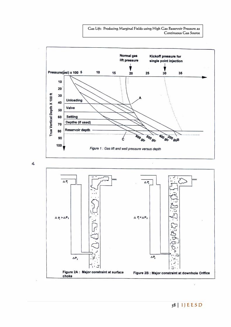
SINGLE POINT INJECTION AND HIGH PRESSURE KICK-OFF:
According to Shotbolti7. “Conventional gas lift technology has only relatively
low continuous-flow gas pressure available, and it depends on gas lift
unloading valves for startup. These valves are located at a series of levels or
stations down the well (production tubing) such that gas in the annulus can
initially enter the tubing liquid at the highest level “. Figure 1 illustrates a
typical design where S valves are required to unload a well to about 8000 ft
using 1800 psi surface pressure as against -a single valve with 3000 psi surface
pressure. Under a normal operating conditions, gas is injected through one
52 | I J E E S D
Gas Lift: Producing Marginal Fields using High Gas Reservoir Pressure as
Continuous Gas Source
valve. Thus the number of side packet mandrels/valves used depends on the
available surface pressure and the optimal fluid level to lift.
Figure 2 illustrates the two major controls for an optimal gas lift system. These
are the gas lift choke (variable) and the down hole orifice. Gas lift mandrels /
dummy valves are normally run during the initial completion of the well.
However, there are cases whereby this may not have been done. If these wells
need to be gas lifted, a full work over has to be carried out to install them. The
production tubing has to be pulled and rerun with gas lift mandrels. This may
not be economically justifiable especially if only marginal recovery is expected
from the field. An economically viable alternative to a full work over is the
installation of pack-off assemblies in the production tubing using wire lines.
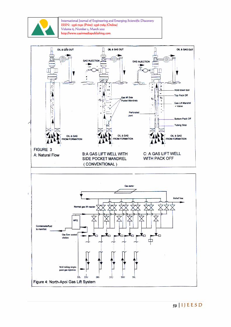
GAS LIFT PACK-OFF SYSTEM INSTALLATION
A pack off system is primarily designed to isolate a hole in the tubing. In a gas
lift pack off installation, a hole is perforated in the tubing with a Kenly
Perforator or an, other type of perforator run on wire line. A pack-off assembly
which Consist of the lower pack-off, conventional gas lift mandrel with a valve
installed and an upper pack-off equipment is run to isolate the bole made in the
tubing. This entire package is designed to provide safety and control for the
gas that will be injected into the well when it is placed o gas lift and it is
entirely installed with wire line (see Figure 31. When the pack-off assenibl3 is
satisfactorily installed in the well, gas injection ma, be initiated to unload the
well. The valve is placed at an optimum depth so that the available gas
pressure will be used to lift the lye!1 from the deepest possible position. A time
saving option if done safely is to unload the well after perforating the tubing
and the Perforator is retrieved from the well and before the installation of the
pack off assembly. After the well is unloaded and kicked off, gas injection may
then be optimized by ensuring that the proper amount of gas is injected for the
desirable production rates. Gas lift optimization techniques have been
discussed by Kanu 7,8,9,10 and is fully applicable to single point gas lift
injection wells with pack-off installations.
SOURCING HIGH PRESSURE GAS FOR CONTINUOUS GAS LIFTING
There are two major sources of high pressure gas for gas lifting system. These
are; corn pressing of produced as from pressure range of 2O-2O psi to about
1000-2000 psi required for injection. This process could he termed recycle gas
process. The other source is to produce a high pressure gas reservoir (already
compressed). Strip it of a fluid at surface using high pressure separator, before

53 | I J E E S D
International Journal of Engineering and Emerging Scientific Discovery
ISSN: 2536-7250 (Print): 2536-7269 (Online)
Volume 6, Number 1, March 2021
http://www.casirmediapublishing.com
injection. The economies associated with the sources depend the oil production
environment of the field under consideration. For major oil fields that requires
high volume of gas. It is more economical to install gas compressor with the
associated facilities especially, in a land location where space is not a limiting
factor. However, where the field is marginal and where wells may be drilled on
clustered area. ii is economical to source gas from any gas reservoir that
transverses the field. It should be noted that some of the gas reservoirs
intercalated in the oil field will never be economical to produce before or after
the abandonment of the oil field. Secondly this marginal field may not be viable
to produce with any other secondary recovery method. Thus substantial oil and
the gas reserves may he left in place rather than producing both by using the
gas to lift the oil at optimal and economic conditions.
NIGERIAN CASE
In the Nigerian case, all the advantages of gas lift are fully appreciated and
integrated into the secondary recovery systems. However, a review of
Nigerian reservoirs and production environment reveal some unique factors
that may be used under certain circumstances to convert some of the
disadvantages of gas lift into significant economic benefits. Such factors are;
(a) Most oil fields in Nigeria have water drive reservoirs,
(b) Most wells cut through several hydrocarbon pay zones in which some are
large/high pressure gas sands exist,
(c) Some so called “Marginal” wells can still be produced at economically
justifiable rates even with the high water cuts,
(d) Ample availability of non corrosive high pressure associated gas at minimal
cost.
Many old wells in Nigeria were not completed nub gas lift mandrels during
their initial completion. These wells, lend to produce with high water cuts as
the oil leg depletes and some, sells ma-, even “load” fluid iii the tubing and die.
Some of the wells may leave substantial recoverable reserves in the reservoir.
In cases like these, the combination of proper planning, utilization of the
available resources such as gas and a careful execution of gas lift installation
may result in the recovery of sizable reserves which otherwise would be
abandoned. This can be done without the expense of a full work over by
employing wire line techniques for the installation of gas lift pack-off system.
FIELD CASES IN NIGERIA
54 | I J E E S D
Gas Lift: Producing Marginal Fields using High Gas Reservoir Pressure as
Continuous Gas Source
Several Nigerian operators have successfully adopted the Gas lift Pack-off
technique to lift their wells and produced hundreds of thousands of barrels of
oil from otherwise unrecoverable reserves. Texaco Overseas Petroleum
(Nigeria) Company Unlimited, TOPCON, Elf Petroleum (Nigeria)
Limited and Ashland Oil (Nigeria) Company Unlimited, are sonic of the
companies that have used this technique with significant success.
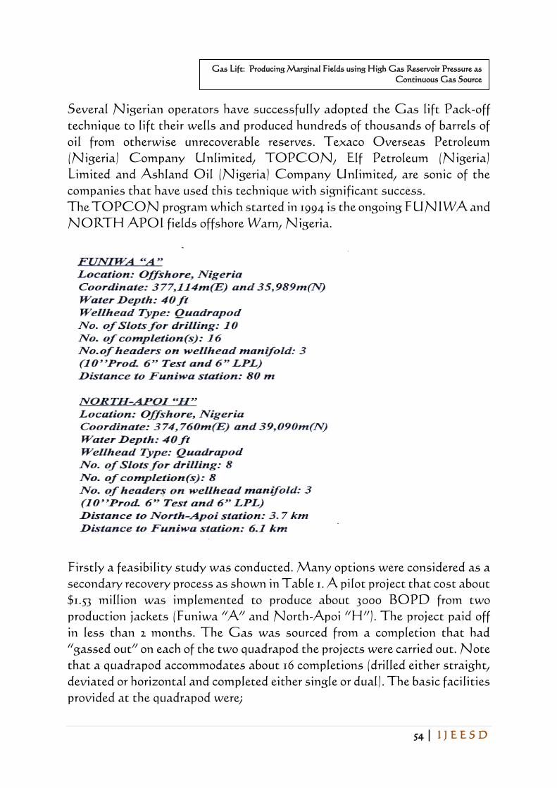
The TOPCON program which started in 1994 is the ongoing FUNIWA and
NORTH APOI fields offshore Warn, Nigeria.
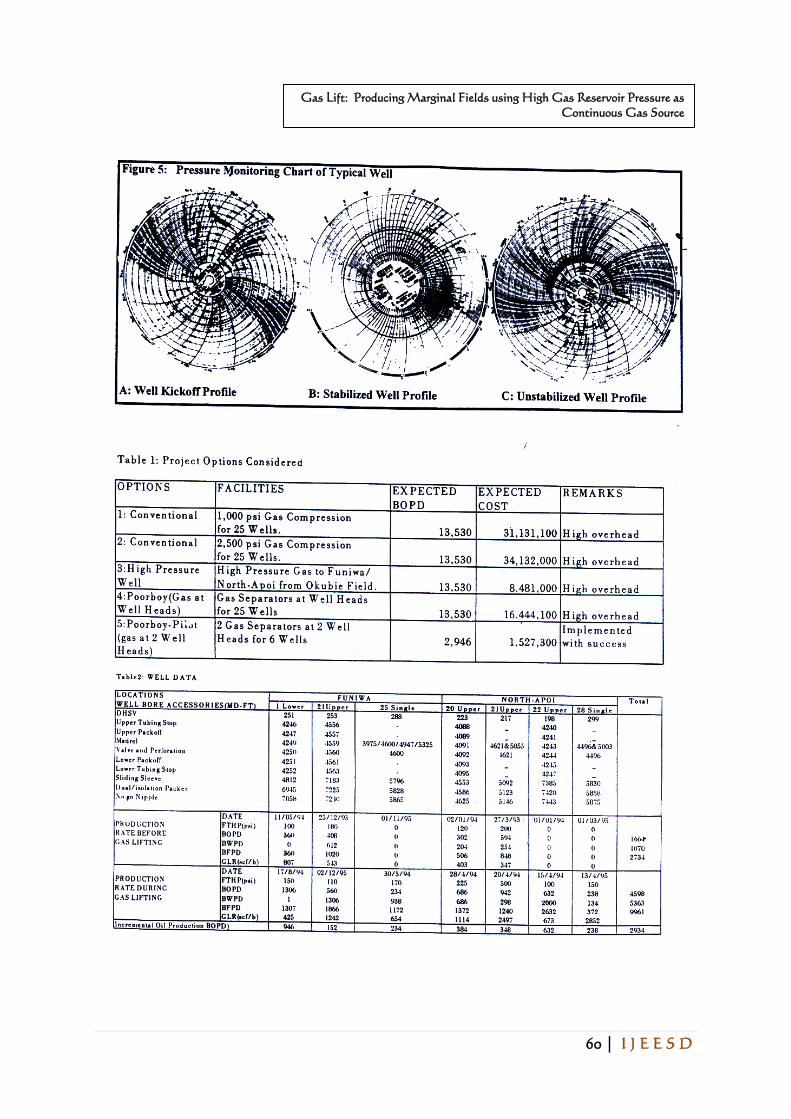
Firstly a feasibility study was conducted. Many options were considered as a
secondary recovery process as shown in Table 1. A pilot project that cost about
$1.53 million was implemented to produce about 3000 BOPD from two
production jackets (Funiwa “A” and North-Apoi “H”). The project paid off
in less than 2 months. The Gas was sourced from a completion that had
“gassed out” on each of the two quadrapod the projects were carried out. Note
that a quadrapod accommodates about 16 completions (drilled either straight,
deviated or horizontal and completed either single or dual). The basic facilities
provided at the quadrapod were;
55 | I J E E S D
International Journal of Engineering and Emerging Scientific Discovery
ISSN: 2536-7250 (Print): 2536-7269 (Online)
Volume 6, Number 1, March 2021
http://www.casirmediapublishing.com
1. High pressure separator (6 mmscf and 600 stb),
2. Gas distribution manifold
3. Hook-up lines with Surface Gas Injection rate
This is illustrated in Figure 4. This could be compared with about $34.3 million
required to recycle produced gas through compression and distribution system.
This excludes the associated overhead cost of equipment attendance and
maintenance. Initially none of the wells bad gas lift mandrels since gas lilting
was not planned for the field. Consequently, to condition the wells for gas
injection at economic rate, the pack-off system was adopted. However for
subsequent well completed or worked over, gas lift mandrels were installed.
The profile of the pressure monitored during unloading process of one of the
wells is shown in Figure 5a. About 2500 psi pressure was required to unload
the completion fluid at the depth of 4000 ft (TVD), thereafter, the pressure
dropped and stabilized at about 1000 psi injection pressure. For a normal
operation, the Flowing Tubing Head Pressure (FTIIP) and the Casing
Injection Pressure (UP) are supposed to form a concentric circles as shown in
Figure Sb. The inner one being the TTUP while the outer is the CIP. An
erratic FFHP as shown in Figure 5c, is an indication of problem i.e. caused by
over injection, injection valve damage etc. The performance of some of the
wells before and after they were put on gas lift is as shown in Table 2. Some
that were flowing below optimal rate, increased production while some that
could not initially flow due to water log, started flowing but with substantial
increase in water cut. For two years since the project commenced, TOPCON
has a steady 3000 BOPD incremental production due to Gas lifting.
CONCLUSION
Texaco’s success is especially significant in the illustration of the fact that a
proper combination of available inexpensive high pressure gas, and technique
to recover a lot of oil from marginal fields. In so doing, convert some
disadvantages of conventional gas lift into economic benefits in Nigeria. It is
believed that this technique can be more widely applied to marginal oil fields
in this country. It has highlighted the unique opportunity that exists in
Nigeria where single point gas lift injection technique can be used to recover
millions of barrels of oil. This is possible due to the favorable factors that are
prevalent thus;
- A of pockets of high pressure gas.
- Over 60% of the reservoirs are water-drive.

56 | I J E E S D
Gas Lift: Producing Marginal Fields using High Gas Reservoir Pressure as
Continuous Gas Source
- Sand production is tolerable by gas lift
- Most wells are dual production which are well suited for gas lift- In offshore
locations, most wells are clustered on platform thereby providing a central
location for gas lift installation for many wells.- Relatively inexpensive to
install pack-off equipment.
REFERENCES
1. Arhagba, A. F. U; “The Search for Dynamic Gas, Policy for Nigerian Gas
Industry Development and Management” Society of Petroleum Engineers,
Nigeria Council-1993, 123-134.
2. Brown, Kermit E. “The Technology of Artificial Lift Method Volume 3a
Pressure Gradient Curve” Penn Well Publishing Company, 1421 South
Sheridam Road, P.O. Box 1260 Tulsa, Oklahoma 74101, 1980.
3. Brown, Kermit E; “Overview of Artifcial Lift Systems” Journal of
Petroleum Technology, 1982, 2384-2396.
4. Brown, Kermit E; “The Technology of Artificial Lift Method Volume 4.
Production Optimization of Oil and Gas Wells by Nodal System
Analysis” Penn Well Publishing
Company, 1421 South Sheridam Road, P. O. Box 1260 Tulsa, Oklahoma
74101, 1984.
5. Bucaram, S.M. and Patterson, J.C; “Managing Artificial Lift” Journal of
Petroleum Technology, April 1994, 335-340
6. Clegg, J.D., Bucaram, S. M. and Hein, N.W Jr. “Recommendations and
Comparisons for selecting Artificial-Lift Methods” Journal of Petroleum
Technology, December 1993, 1128-1167.
7. Harald Ashelm; Criteria for Gas-Lift Stability” Journal of Petroleum
Technology, November 1988, 1452-1456.
57 | I J E E S D
International Journal of Engineering and Emerging Scientific Discovery
ISSN: 2536-7250 (Print): 2536-7269 (Online)
Volume 6, Number 1, March 2021
http://www.casirmediapublishing.com
8. Hepguler, G., Schmidt, Z., Bials, R. and Doty, D. R; “Dynamic Model of
Gas Lift Valve Performance” Journal of Petroleum Technology, June 1993,
576-583.
9. Kanu, E.P. Mach, J., Brown, K.E; “Economics Approach to Oil Production
and Allocation in Continuous Gas Lift” Journal of Petroleum Technology,
October 1981, 1887-1892.
10. Kanu, Eni P. “System Analysis, Quality Data Ensure Gas-Lift
Optimization” Petroleum Engineer International, March 1992, 72-76.
11. Keelim, Richard F. “Gas lift; How to make the most of it Part 1- Use of
Fluid Aeration for Pressure Reduction” Petroleum Engineering
International, April 1985, 26-34.
12. Keelim, Richard F. “Gas lift; How to make the most of it Part 3- Field
Analysis of Flowing and Gas Lift Wells” Petroleum Engineering
International, June 1985, 48-56.
13. Ojinnaka, I. P; “Energy Policy: Appropriate Pricing of Nigeria’s Natural
Gas” Society of Petroleum Engineers, Nigeria Council-1993, 135-140.
14. Patton, Douglas L; “Optimize Production through Balanced Reservoir
Depletion, Part 1- Methods and Data Required” Petroleum Engineer
International, July 1988.
15. Patton, Douglas L, Patton, L.D. and Associates, Aurora, Colo;
“Optimize Production with Artificial Lift Systems, Part 2- How to lower
Operating Costs” Petroleum Engineer International, October 1989, 26/30.
16. Patton, Douglas L, Patton, L.D. And Associates, Aurora, Colo;
“Optimize Production with Artificial Lift Systems, Part 2 – How to lower
Operating Costs” Petroleum Engineer International, October 1989, 26/30.
58 | I J E E S D
Gas Lift: Producing Marginal Fields using High Gas Reservoir Pressure as
Continuous Gas Source
59 | I J E E S D
International Journal of Engineering and Emerging Scientific Discovery
ISSN: 2536-7250 (Print): 2536-7269 (Online)
Volume 6, Number 1, March 2021
http://www.casirmediapublishing.com
60 | I J E E S D
Gas Lift: Producing Marginal Fields using High Gas Reservoir Pressure as
Continuous Gas Source