welding update - hard facing by welding in marine environments
TRANSCRIPT

1
Hard facing by welding in marine environment
We think that welding is synonymous with joining. That is not always the case. Metal parts often fail their intended use not because they fracture, but because they wear down, which causes them to lose dimension and functionality. Hard facing by weld build up, also known as hard surfacing is the application of build-up or wear-resistant weld metals to a part's surface by means of welding.
TECHNICAL UPDATE

2
INDEX:
General information 3
Benefits of hard facing 3
Terminology 4
Consumable Selection 6
Base Metal 6
Type of wear and choise of consumable 7
Classification of electrodes for hard facing 10
DIN 8555 10
AWS A5.13 12
DIN EN 14700 14
Hard facing family group 19
Welding Method 27
Important details to take into consideration during welding 28
General welding procedures 29
General wear problems onboard ships 32
Ship’s Mooring Equipment 32
Engine parts 41
Ships with special wear problems 44
Bulk carriers/ Wear patterns/Wear plates 44
Dredgers 55
Cement carriers 60
MMAW Electrodes and Self-Shielded (FCAW-S) wire Hard facing Comparison Chart 61
Ships propeller repair 67
Alternative hard facing methods and materials 69
Summing up 70
TECHNICAL UPDATE

3
General information
Star International brings you this latest welding update, detailing classification systems for weldingconsumables like electrodes, that exist in order to guide users towards the products chemistry,mechanical properties and application area.
Hard facing consumable manufacturers do have classification systems available. Despite this fact some manufacturers do not inform classification at all, or informs “similarly” to a specific classification.
Contrary to standard consumables for joining, hard facing consumables with few exceptions have no general approvals from the classification societies (DNV/GL, ABS, BV, LRS). Classification societies will however approve specific hard facing jobs from case to case.
The electrodes for hard facing are produced in two ways: 1) Like other standard electrodes, a metal rod coated with a mix of alloys and deoxidizers. 2) tubular rod filled with an alloy mix and then dipped in a coating or has a coating extruded over it.
Onboard a vessel there will with few exceptions be used MMAW (stick electrode welding) for hard facing. The consumable charts and comparison charts in this paper gives suggested stick electrodes for MMAW according to classification. There is also charts for Wire Welding processes using tubular
Flux Cored Arc Welding wire (FCAW-S). This is referred to as Self-Shielded or as Open Arc wire.
The comparison charts are based on resemblance with regards to classification. Please note that the classifications alloy groups have lower and upper limit range on elements that can be quite considerable. This can also be the case for mechanical values (hardness). The comparison has not taken into account if the consumable is high or normal recovery type or if it can be used in different positions. The same applies if the consumable can be used for AC and/or DC current and polarity. It is
therefore advisable to contact the manufacturer for finer details and for last updates.
In some cases, electrodes and wires is mentioned by their trade names based on their track records for a specific application. Other electrodes and wire brands with same classification is also mentioned
but should be closely checked before use.
Benefits of hard facing:
• Fewer replacement parts needed. There is no need to keep numerous spare parts when wornparts can be rebuilt.
• Prolong equipment life - Surfacing extends life 30 - 300 times, depending upon application, ascompared to that of a non-surfaced part.
• Operating efficiency is increased by reducing downtime. Parts last longer, fewer shutdownsare required to replace them.
• Overall costs are reduced. Hard facing a worn metal part to like new condition is usually 25 -75% of the cost of a replacement part.
Wear and tear on ships equipment makes maintenance in the form of Hard Facing Welding necessary. To keep operational cost down it is important to get it right first time using the right welding methods and consumables.
TECHNICAL UPDATE

4
Terminology:
Hard facing and restoring worn parts frequently involves the following three steps:
1. Buttering, also referred to as buffer deposit or transition deposit is the addition of a weld deposit onthe surface of a base material providing a suitable transition deposit, prior to the deposit of the final harfacing deposit. Without the buttering deposit the final deposit would in some cases not metallurgicallybe compatible to the base material. Buttering can also be put to use in connection with joining of un-compatible base materials.
Buttering is also used in order to minimize dilution. Dilution will be explained later.
• Most hard facing alloys are limited to two or three layers, some only one. Therefore, someapplications require that a buttering intermediate layer be used to build up the part close to finishdimensions prior to depositing a harder, more abrasion resistant alloy.
• When hard materials are used on soft base metals, such as mild steel, there is a tendency forthe hard facing layer to “sink” into the soft base metal under high load conditions. This mayresult in spalling** of the hard-facing alloy. An intermediate buttering layer will help to preventthis from happening.
• Hard facing alloys sometimes check-crack* throughout the deposit. The buttering layer helps toprevent these cracks from propagating into the parent metal.
• If the surface conditions involve thermal cycling, large thermal property differences between theparent metal and the overlay can lead to fatigue problems and spalling. The deposition of abuffer layer provides a very effective transition between the weld and the overlay.
• Never us AWS E-7018*** electrode as buttering or build-up. It does not have the hardness andstrength for hard facing applications.
* Check-crack: Some hard-facing weld deposits crack upon cooling, often referred to as "stress relief cracking" "check cracking" or "cross checking". Essentially all these terms refer to the same surface cracks observed on some hard-facing alloys. This is anormal phenomenon for very hard weld deposits. Many chromium carbides alloys check-crack when cooled to moderatetemperatures. Others, such as the austenitic and martensitic families, don't crack when applied with proper welding procedures.
**Spalling are flakes of a material that are broken off a larger solid body and can be produced by a variety of mechanisms,
including as a result of impact or excessive rolling pressure.
***AWS-E 7018: This is a common low hydrogen basic coated electrode for joining of mild and low alloyed steel.
Buttering deposit (Transition/buffer
deposit) Final hard facing deposit Buttering deposit
Buttering un-compatible base materials
Buttering un-compatible base material and hard facing
TECHNICAL UPDATE

5
2. Build-up layer — A build-up layer can consist of alloys that often resemble the parent metal alloyand are applied to severely worn parts to bring them back to dimension or act as a buffer forsubsequent layers of a more wear-resistant hard facing deposit. Seriously worn areas should berebuilt close to working size using tough, crack-resistant welding materials which can be deposited inan unlimited number of layers.
As already explained the buttering layer, is used when necessary to overcome problems of incompatibility between base material and hard facing alloy. The use of a buttering layer is to provide a good base between the base metal and the hard facing. Great care must be taken when choosing the filler metal for the buttering layer. If differences in elasticity or thermal expansion between the base metal, buttering and hard facing deposit are too great, excessive stresses may be generated at the weld joints. This may cause it to fail prematurely.
3. Hard facing — Wear resistant surfaces deposited on the buttering or on build-up deposits extendservice life. As mention previusly hardfacing is usually limited to one, two, or three layers. The hard-facing layer must be an alloy that can take the type of wear that apply to the part.
Hard facing without a build-up and buttering deposit can lead to cracks developing into the base material.
Build-up
Hard facing
Buttering layer
Buttering layer (Transition/buffer
deposit) Hard facing deposit
Build-up deposit
TECHNICAL UPDATE

6
Consumable Selection
The whole idea of consumable selection is to find a consumable and welding process that in combination is the most efficient for the application, suits the base material and to the extent posible withstand the type of wear that the part will encounter. Welding consumable selection for hard surfacing depends upon three major factors:
.
Base Metal
This primarily affects the choice of build-up and/or buttering materials. The following base metals can be hard-faced:
Stainless steels Manganese steels Cast irons and steels Nickel-base alloys Copper-base alloys
For example manganese steel is used for components subject to high impact loading. If so, one have to build up to size using a weld deposit suitable to manganese steel.
Base Metal
Type of wear and choise of Consumable
Welding method
TECHNICAL UPDATE

7
Type of wear and choise of consumable
The primary consideration in selecting the final hard facing layers is the type of wear to be encountered in service. There are six major types of wear: Abrasive, Impact, Cavitation, Adhesive, High Temperature and Corrosive. Onboard a dredger abrasion can account for roughly 50 % of equipment wear, Impact 25 %, Adhesive (Metallic/metal to metal) 10 %, Heat 5%, Corrosion 5%, Other (like cavitation) 5 %.
Note that abrasive wear is really a group of wear problems. It can be broken down into three main categories that are “Low-stress scratching abrasion”, “High-stress grinding abrasion” and “Gouging abrasion”. Abrasion is also refered to as erosion.
Abrasive
Low-stress scratching abrasion
High-stress grinding abrasion
Gouging abrasion
Wear factors
Abrasive wear is caused by foreign materials rubbing against a metal part. It can account for 50 - 60% of all wear onboard depending on type of vessel. Abrasive wear can be broken down into three main categories:
Metal parts are worn away through the repeated scouring action of hard, sharp particles moving across a metal surface at varying velocities. The velocity, hardness, edge sharpness, angle of introduction and size of the abrasive particles all combine to affect the amount of abrasion.
This results when small hard abrasive particles are forced against a metal surface with enough force that the particle is crushed, in a grinding mode. Most often the compressive force is supplied by two metal components with the abrasive sandwiched between the two. The surface becomes scored and surface cracking can occur.
When high-stress or low-stress abrasion is accompanied by some degree of impact and weight, the resulting wear can be extreme. The metal surface receives prominent gouges and grooves when massive objects (often rock) are forced with pressure against it.
Carbide containing alloys (particularly chrome-carbide) are used successfully to resist low-stress abrasive wear. Due to the absence of impact, the relatively brittle high carbon chromium steel alloys are well suited for low-stress abrasive applications.
There are examples of softer, tough alloys outperforming harder alloys in grinding abrasion applications. The range of alloys used successfully includes austenitic manganese, martensitic irons, and some carbide containing alloys (usually smaller carbides, like titanium carbide) in a tough matrix.
Carbide containing alloys are used successfully when supported by a tough alloy - preferably austenitic manganese.
TECHNICAL UPDATE

8
In most cases, the wear found will be a combination of two or more of the mentioned wear factors described.
* GPa: gigapascal. 1,5 GPa= 1500000000 Pa. A pascal (Pa) is the SI derived unit of pressure, stress, Young’s modulus andultimate tensile strength. It is a measure of force per unit area, defined as one newton per square meter.
Impact
Adhesive
Cavitation
High temperature
Adhesive (Metal-to-metal) wear, accounting for as much as 15% of all wear, results from non-lubricated friction of metal parts. Metal surfaces regardless of their finish, are composed of microscopic high and low areas. As metal surfaces slide against each other, the high areas are broken and tiny fragments of metal are torn away. The continual removal of metal roughens the working surface and contributes to even more rapid wear.
Ferrous metals are subjected to many forms of corrosion, each of which can cause wear damage. The most common type of corrosion is rust. Rust transforms the surface of the metal into oxide which eventually flakes off, thus reducing the original thickness of the metal.
Cavitation is happening in fluid flow environment. The wear occurs from the collapse of cavitation bubbles. When a cavitation bubble collapses, the surrounding liquid rushes to refill the void and collides with the material surface. Transient pressures as high as 1.5 GPa* can form at the surface. Parts fallen victim to suction cavitation will have large chunks or very small bits of material missing, causing it to look like a sponge.
Steel surfaces exposed to high temperatures for long periods of time can steadily deteriorate. Heat affects the metal’s microstructure and generally reduces its durability. The wear resistance of most alloys is diminished when exposed to high heat in service due to softening through inadvertent tempering.
Cobalt-based alloys. Austenitic-type alloys containing controlled amounts of chromium, cobalt, silicon and manganese. Also, to be considered is ceramic polymers.
Martensitic steels containing 5 - 12% chromium are used extensively to combat thermal fatigue. Many chromium-carbide alloys retain their wear resistance up to temperatures of 650°C (1200°F) - service conditions over that temperature generally require a non-ferrous alloy. Cobalt based alloys belong to the group of deposits that can resist temperatures up to 900°C (1650°F).
Corrosion as related to surfacing is usually a secondary wear factor. To meet this challenge, austenitic stainless steels (300 series) and nickel base alloys are preferred.
Corrosive
The martensitic hard surfacing alloys are a good choice for adhesive wear resistance. Other alloys, including austenitic manganese and cobalt based alloys, are also used successfully. Since softer alloys matched with a harder surface will wear rapidly, it is important not to overmatch a component when hard surfacing for adhesive wear resistance.
Impact is defined as the rapid application of a compressive load, produces momentary, extremely high mechanical stress on a metal component. When the stress exceeds the elastic limits of the metal, the metal deforms both beneath point and laterally across the surface away from the impact point.
Austenitic manganese steels (11 - 20% Mn) are the best choice for resisting heavy impact due to their work hardening characteristics. Although not as good as austenitic manganese, the martensitic alloys also offer moderate impact resistance.
TECHNICAL UPDATE

9
Identifying the type of wear involved.
What is the part used for? What is the working environment? By simply asking these questions it will be possible to identify the type of wear involved. If abrasive wear check out the following: Type of product causing the wear. The hardness of the particles in the product. The size of the particles, edge sharpness, velocity and the angle of introduction towards the substrat.
Abrasive wear. How to recognise: The surface will be ploughed and depending on product sometime have deep grooves.
Cavitation wear. How to recognise: Pitting corrosion sometime over large surface areas. Will only take place in fluid flow environment.
Impact wear. How to recognise: Collisions between solid bodies making dents in substate and in some cases cracks and chipping/ breaking off parts.
High Temperature wear How to recognise: Pitting’s and craters. Will only take place in hot environment.
Adhesive wear How to recognise: Scratched surface. Tiny metal fragments to be found.
Corrosive wear How to recognise: Oxidised surface. Sometime oxide flakes.
TECHNICAL UPDATE

10
Classification of electrodes for hard facing
After establishing type of wear, the next step is to decide on consumable to match the type of wear. This can also involve type of butter/ build up consumable to use. The classifications most referred to are DIN 8555, AWS A5.13 and DIN EN 14700.
Filler Materials for Surfacing According to DIN 8555 Exsample: EutecTrode 6450 DIN 8555: E 7-UM-250 KPR
E Short symbol for Manual Metal Arc Welding
MSG Short symbol for Solid wire Gas shielded arc welding
MF Short symbol for tubular wire (metal or flux cored)
Short symbol
Alloy group and application
1 Unalloyed up to 0.4% C or low-alloyed up to 0.4% C and up to max. 5 % alloy constituents Cr, Mn, Mo, Ni in total; soft surfacing, e. g. build-up welding, buffering layers.
2 Unalloyed with more than 0.4% C or low-alloyed with more than 0.4%C and up to max. 5% alloy constituents Cr, Mn, Mo, Ni in total; Running wheels.
3 Alloyed, with the properties of hot working steel. Hot working tools
4 Alloyed, with the properties of high-speed steel. Cutting tools, mandrels, shear blades, cutters, drill bits.
5 Alloyed with more than 5% Cr and low C-content (up to approx. 0.2%C) for scale-resistant (also against sulphurous gases) and from 12% Cr-content corrosion-resistant surfacing, e. g. valve parts, plungers, furnace parts
6 Alloyed with more than 5% Cr and higher C-content (approx. 0.2 - 2.0% C) cutting tools, shear blades, rollers for cold rolling mills
7 Mn austenite with 11 to 18% Mn and more than 0.5% C and up to 3% Ni. Surfacing large surfaces, e. g. wear plates, jaw plates, digging teeth, bolts
8 Cr-Ni-Mn-austenite crusher parts for medium stress, switch tongue, rails, water turbine parts
9 Cr-Ni-steel (corrosion and heat resistant) corrosion and heat resistant surfacing
10 High C-content and high Cr-alloyed with and without additional carbide former, repairs on mining and steel plant equipment, surfacing on machine parts in the construction industry and agriculture, overburden excavators, sinter crushers
20 Co-based, Cr-W-alloyed, with or without Ni and Mo fittings of all types, valve seats of exhaust valves in combustion engines, valve seats of steam engines, pump shafts and similar parts which are exposed to heavy corrosion and erosion
21 Carbide-based (sintered, cast or filled) tools and machine parts for working in stony earth, drills and similar tools, press screws in the ceramic industry
22 Ni-based, Cr-alloyed, Cr-B-alloyed valves, screws, shafts, e.g. for concrete pumps
23 Ni-based, Mo-alloyed with or without Cr hot working tools, contact surfaces of valves in chemical apparatuses, claddings at working edges of cuttings from Ni-Cr-Mo-alloys which are used for work at high temperatures
30 Cu-based, Sn-alloyed bearing shell, slides, shafts, valves, housings, snail and helical gear wheels, guide and running wheels, fittings
31 Cu-based, Al-alloyed machine parts and fittings in the chemical industry, food, paper and electrical industry
32 Cu-based, Ni-alloyed. Distillatory, sea water pipes, condensers, coolers, chemical apparatuses, heat exchangers
E 7-UM-250 KPR
TECHNICAL UPDATE
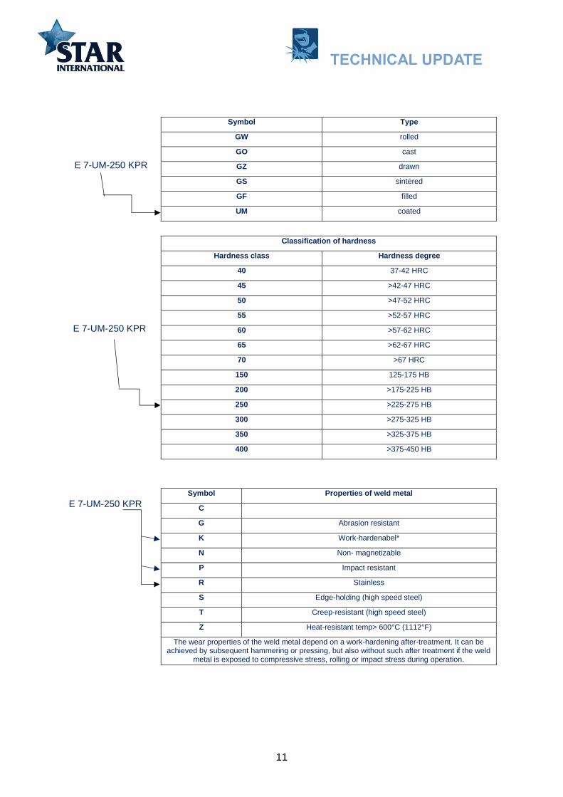
11
Symbol Type
GW rolled
GO cast
GZ drawn
GS sintered
GF filled
UM coated
Classification of hardness
Hardness class Hardness degree
40 37-42 HRC
45 >42-47 HRC
50 >47-52 HRC
55 >52-57 HRC
60 >57-62 HRC
65 >62-67 HRC
70 >67 HRC
150 125-175 HB
200 >175-225 HB
250 >225-275 HB
300 >275-325 HB
350 >325-375 HB
400 >375-450 HB
Symbol Properties of weld metal
C
G Abrasion resistant
K Work-hardenabel*
N Non- magnetizable
P Impact resistant
R Stainless
S Edge-holding (high speed steel)
T Creep-resistant (high speed steel)
Z Heat-resistant temp> 600°C (1112°F)
The wear properties of the weld metal depend on a work-hardening after-treatment. It can be achieved by subsequent hammering or pressing, but also without such after treatment if the weld
metal is exposed to compressive stress, rolling or impact stress during operation.
E 7-UM-250 KPR
E 7-UM-250 KPR
E 7-UM-250 KPR
TECHNICAL UPDATE
12
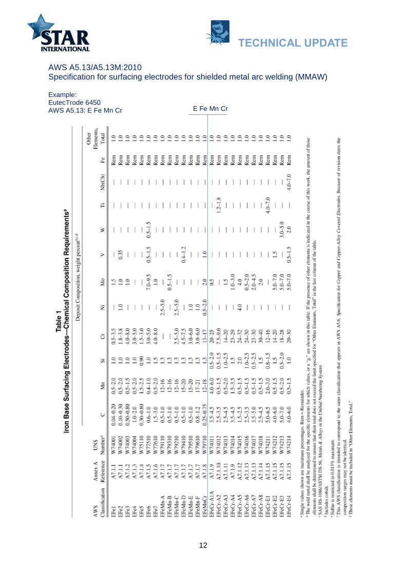
AWS A5.13/A5.13M:2010 Specification for surfacing electrodes for shielded metal arc welding (MMAW)
Example: EutecTrode 6450 AWS A5.13: E Fe Mn Cr E Fe Mn Cr
TECHNICAL UPDATE

13
AWS A5.13/A5.13M:2010 covers hard facing electrodes: Iron Base Surfacing Electrodes Table 1. Nickel and Cobalt Base Surfacing Electrodes Table 2. Copper Base Surfacing Electrodes Table 3 (page 65). Tungsten Carbide Surfacing Electrodes Table 4 (partly covered).
TECHNICAL UPDATE

14
Filler Materials for Hard-facing According to DIN EN 14700
Symbols for range of product form
Symbol Product form (consumable)
E Covered electrode
S Solid wire and solid rod
T Cored wire and cored rod
R Cast rod
B Solid strip
C Sintered rod, cored strip and sintered strip
P Metal powder
Symbols for range of chemical composition
Alloy
abbreviation
*a
Suitability
Chemical composition in % (by mass)
C Cr Ni Mn Mo W V Nb Others Remainder
Fe1 p < 0.4 <3.5 – 0.5–3 <1 <1 <1 – – Fe
Fe2 p 0.4–
1.2 <7 <1 0.5–3 <1 <1 <1 – – Fe
Fe3 s t 0.2–
0.5 1–8 <5 <3 <4.5 <10 <1.5 – Co, Si Fe
Fe4 s t (p) 0.2–
1.5 2–6 <4 <3 <10 <19 <4 – Co, Ti Fe
Fe5 c p s t w <0.5 <0.1 17–22 <1 3–5 – – – Co, Al Fe
Fe6 g p s <2.5 <10 – <3 <3 – – <10 Ti Fe
Fe7 c p t <0.2 4–30 <6 <3 <2 – <1 <1 Si Fe
Fe8 g p t 0.2–2 5–18 – 0.3–3 <4.5 <2 <2 <10 Si, Ti Fe
Fe9 k (n) p 0.3–
1.2 <19 <3 11–18 <2 – <1 – Ti Fe
Fe10 c k (n) p z <0.25 17–22 7–11 3–8 <1.5 – – <1.5 Si Fe
Fe11 c n z <0.3 18–31 8–20 <3 <4 – – <1.5 Cu Fe
Fe12 c (n) z <0.08 17–
26
9–
26
0.5–
3 <4 – – <1.5 – Fe
Example: UTP electrode BMC DIN EN 14700: EFe9
EFe9
TECHNICAL UPDATE

15
Symbols for range of chemical composition (Continue)
Alloy
abbreviation
*a
Suitability
Chemical composition in % (by mass)
C Cr Ni Mn Mo W V Nb Others Reminder
Fe13 g <1.5 <6.5 <4 0.5–3 <4 – – – B, Ti Fe
Fe14 g 1.5–4.5 25–40 <4 0.5–3 <4 – – – – Fe
Fe15 g 4.5–5.5 20–40 <4 0.5–3 <2 – – <10 B Fe
Fe16 g z 4.5–7.5 10–40 – <3 <9 <8 <10 <10 B, Co Fe
Fe20 c g t z Hard
materials*b – – – – – – – – Fe
Ni1 c p t <1 15–30 Rest 0,3–1 <6 <2 <1 – Si, Fe, B Ni
Ni2 c k p t z <0,1 15–30 Rest <1,5 <28 <8 <1 <4 Co, Si, Ti Ni
Ni3 c p t <1 1–15 Rest 0,3–1 <6 <2 <1 – Si, Fe, B Ni
Ni4 c k p t z <0,1 1–15 Rest <1,5 <28 <8 <1 <4 Co, Si, Ti Ni
Ni20 c g t z Hard
materials*b – – – – – – – – Ni
Co1 c k t z <0.6 20–35 <10 0.1–2 <10 <15 – <1 Fe Co
Co2 t z (c s) 0.6–3 20–35 <4 0.1–2 – 4–10 – – Fe Co
Co3 t z (c s) 1–3 20–35 <4 <2 <1 6–14 – – Fe Co
Cu1 c (n) – – <6 <15 – – – – Al, Fe, Sn Cu
Al1 c n – – 10–35 <0.5 – – – – Cu,Si Al
Cr g n 1–5 Rest – <1 – – 15–30 – Fe, B, Si, Zr Cr
Filler Materials for Hard-facin
Example: UTP electrode BMC DIN EN 14700: EFe9
c: corrosion-resistant g: abrasion-resistant k: work-hard enable n: non-magnetizable p: impact-resistant s: cutting power-resistant t: heat resistant z: scale-resistant w: age-artificially () perhaps not suitable for all alloys in this list
*a Alloys not listed in this table should be marked "similar" with the prefix "Z".
*b Tungsten carbide or cemented tungsten carbide broken or spherical.
TECHNICAL UPDATE
16
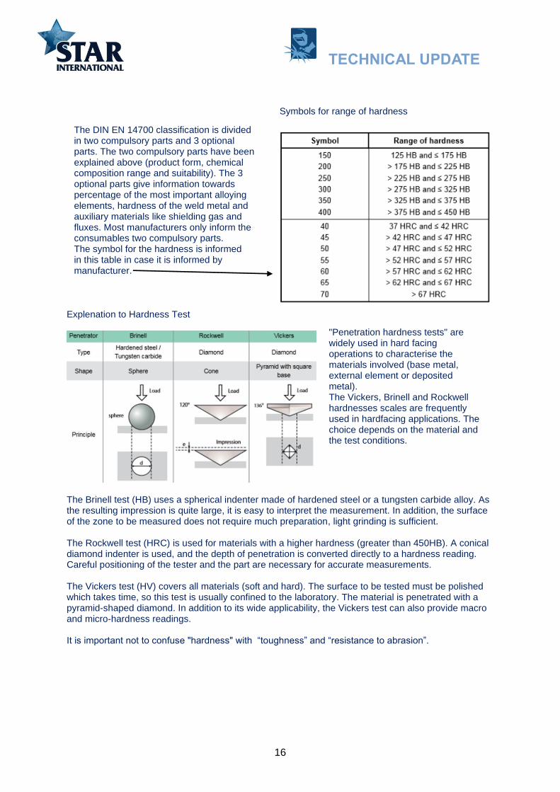
Symbols for range of hardness
Explenation to Hardness Test
The Brinell test (HB) uses a spherical indenter made of hardened steel or a tungsten carbide alloy. As the resulting impression is quite large, it is easy to interpret the measurement. In addition, the surface of the zone to be measured does not require much preparation, light grinding is sufficient.
The Rockwell test (HRC) is used for materials with a higher hardness (greater than 450HB). A conical diamond indenter is used, and the depth of penetration is converted directly to a hardness reading. Careful positioning of the tester and the part are necessary for accurate measurements.
The Vickers test (HV) covers all materials (soft and hard). The surface to be tested must be polished which takes time, so this test is usually confined to the laboratory. The material is penetrated with a pyramid-shaped diamond. In addition to its wide applicability, the Vickers test can also provide macro and micro-hardness readings.
It is important not to confuse "hardness" with “toughness” and “resistance to abrasion”.
The DIN EN 14700 classification is divided in two compulsory parts and 3 optional parts. The two compulsory parts have been explained above (product form, chemical composition range and suitability). The 3 optional parts give information towards percentage of the most important alloying elements, hardness of the weld metal and auxiliary materials like shielding gas and fluxes. Most manufacturers only inform the consumables two compulsory parts. The symbol for the hardness is informed in this table in case it is informed by manufacturer.
"Penetration hardness tests" are widely used in hard facing operations to characterise the materials involved (base metal, external element or deposited metal). The Vickers, Brinell and Rockwell hardnesses scales are frequently used in hardfacing applications. The choice depends on the material and the test conditions.
TECHNICAL UPDATE

17
Hardness conversion table
Material Hardness (HV)
Coal 32
Gypsum 36
Lime 110
Calcite 140
Fluorspar 140
Coke 200
Material Hardness (HV)
Iron ore 470
Glass 500
Feldspar 600/750
Agglomerate 770
Quartz 900/1280
Corundum 1800
HB HV HRC Tensile Strength
N/mm2
HB HV HRC Tensile Strength
N/mm2
Examples of Vickers hardness values for common materials involved in wear:
TECHNICAL UPDATE

18
The chemical composition given in DIN EN 14700 for the filler metal informs the product’s functionality. Each element or combination of elements in an alloy has a particular function; it can be related to weldability, or especially to the deposit’s physical or mechanical characteristics. In practice, when choosing a filler metal, it is advisable to decide why an element is added. This step is necessary for making the most appropriate choice. The below table describes the main influence of alloy elements in the deposit.
Main influence of alloy elements in the weld deposit.
Description Hardness &
Carbides
Performance
at temperature
Resistance
to shock Ductility Corrosion
C
Carbon is the principal hardening and strengthening
element in iron-based alloys. It can combine with other
elements to form carbides (hard phases). The alloys’
strength and hardening capability improves as the carbon
content increases, whilst elongation and weldability and
machinability decrease.
Cr
Chromium improves heat resistance. Steels require a
minimum chromium content of around 13% to render them
corrosion resistant. Higher Cr contents improve corrosion
and heat resistance. Chromium tends to reduce thermal
conductivity. Chromium is a generator of carbides which has
the effect of improving resistance to wear.
Mo Molybdenum belongs to the category of elements that
increase strength and resistance to corrosion and is therefore
often used in Cr-Ni austenitic steels.
Nb Niobium is a powerful generator of hard carbides. This
element can also be used as a stabiliser in refractory
austenitic steels.
V Vanadium is a generator of carbides and is used to reduce
sensitivity to overheating. Therefore, this element is often
found in high speed hot working steels. ---------
W Tungsten is a powerful generator of very hard carbides.
This element increases the resistance to high temperatures
and is therefore used for tool steel applications. ----------
Ti
Titanium combines easily with other elements such as
oxygen (deoxidising effect) and carbon. Titanium carbide
forms fine particles, providing good resistance to external
shocks.
-----------
Mn
Manganese plays an important role by deoxidizing and
desulphurising weld metal. Where there is over 12%
manganese with a high carbon content, the deposit is
austenitic, thus providing excellent resistance to shock and
wear due to work hardening. Over 18% Manganese, the
deposit becomes non-magnetic.
------------ ------------ -----------
Ni
Nickel is not a carbide former. It substantially improves
impact strength in construction steels. Where its content
exceeds 7% and there is a high chromium content, the
structure becomes austenitic.
------------
Co Cobalt promotes heat resistance by slowing grain growth.
In addition, it provides excellent resistance to corrosion and
erosion.
TECHNICAL UPDATE

19
Hard facing family group.
Filler metals for hard facing can be divided into four groups.
Regarding Iron-base alloys:
Martensitic. This includes all hardenable steels with Rockwell hardness from 20 to 65. This group, similar to tool steel, hardens upon cooling. They are good for metal-to-metal and abrasive wear. They also can withstand a great deal of impact.
Austenitic. Austenitic alloys include work-hardening steels, such as manganese and stainless. This group generally is soft when it's welded and hardens only after the weld metal is worked. They have good impact properties and moderate abrasion resistance. The stainless-steel family is good for corrosion resistance.
Metal carbide. These alloys contain large amounts of metal carbides in a soft, tough matrix and are good for severe-abrasion applications. The alloys that contain large amounts of chromium* and carbon are known as the chromium carbide family and are closer to a cast iron or white iron. Their hardness’s are from 40 HRC to 65 HRC. Alloys that contain large amounts of tungsten and carbon belong to the tungsten carbide family. Some contain small amounts of chromium and boron that form borides and are good for severe-abrasion applications.
*Chromium carbideGenerally, these are iron-base alloys that contain high amounts of chromium (greater than 18 percent) and carbon (greater than3 percent). These elements form hard carbides (chromium carbides) that resist abrasion. The deposits frequently check-crackabout every 12mm (1/2”), which helps relieve stress from welding. Their low friction coefficient also makes them desirable inapplications that require material with good slip. Generally speaking, the abrasion resistance increases as the amount of carbonand chromium increases, although carbon has the most influence. Hardness values range from 40 HRC to 65 HRC. They alsocan contain other elements that can form other carbides or borides that help increase wear resistance in high-temperatureapplications. These alloys are limited to two or three layers.
Group 1: Iron base with less than 20% alloying elements.
Group 2: Iron base with more than 20% alloying elements.
Group 3: Non-ferrous alloys.
Group 4: Tungsten carbide.
Low- alloy steels
Medium alloy steels
Martensitic stainless steels
Tool steels
Austenitic manganese steels
Tool steels
Cobalt base alloy
Austenitic Chromium-Manganese steels
Nickel base alloy
Chromium cast irons
Copper base alloy*
*Consumables for hard facing of copperbase alloys on page 67 in connectionwith ships propeller repair.
TECHNICAL UPDATE

20
Group1: Iron base with less than 20 % alloying elements
Low-alloy steels
These filler metals contain a maximum 0.2% C and hardness after welding does not exceed 250HV. They are produced for use in the rebuilding of parts prior to hardfacing. They provide a metallurgical transition between the soft base metal and the hardfacing. The deposited metal has good mechanical properties and resists compression well. Their composition however, means that these filler metals respond poorly to wear.
Low-alloy steel electrodes for hard facing can in DIN EN 14700 have grading:
DIN EN 14700: EFe1 Typical chemical composition: C 0.15%, Mn 1.50%, Si 0.80%, Cr 1.00%, Fe Rest. Mechanical values: Hardness 3 layers: As welded 260 HB. Crack-resistant deposit. Repair, rebuilding and buttering of castings Applications: shafts, rollers, wheels.
Medium alloy steels
The most commonly used filler metals are those that deposit a martensitic - bainitic structure. These are low - cost filler metals with alloying additions to give wear resistance. As well as carbon, they may contain: Carburigenic elements, such as chromium and molybdenum. They also have elements that refine the structure, such as manganese. Weld deposit hardness may vary from 250 to 700HV. It is useful to note that deposits with hardness less than 300HV are easy to machine, whilst surfacing exceeding 50HRC is usually impossible to machine. The harder the deposit, the greater its resistance to abrasion under low or moderate stresses. Such materials are frequently found in earthmoving activities.
Medium alloy steel electrodes for hard facing can in DIN EN 14700 have grading:
DIN EN 14700: EFe1 As under Low-alloy steel. DIN EN 14700: EFe8 Typical chemical composition: C 0.50%, Mn 1.50%, Si 2.50%, Cr 8.50%, Fe Rest. Mechanical values: Hardness 3 layers: As welded 650 HB. Self-tempering deposit for hard facing. Applications: bucket teeth and blades, slides, conveyor screws, etc.
Martensitic stainless steels
Martensitic stainless steels, with over 12 % Cr, offer good resistance to wear from thermal fatigue and to corrosion. These grades are ideal for applications where there is hot metal-to-metal wear. The addition of elements such as nitrogen and cobalt increases the resistance of these alloys to high temperatures and corrosion. Nitrogen reduces segregation of chromium carbides at the grain boundaries and provides improved resistance to pitting corrosion (PREN=Cr+3.3Mo+16N). Cobalt gives the deposit improved resistance to high temperatures and, therefore, to both thermal fatigue and high temperature corrosion. When surfacing a low or medium alloy base metal with martensitic stainless steels, it is advantageous to apply a special butter layer over-alloyed in chromium (~ 17%) to guarantee metallurgical soundness and to avoid cracking in service.
Martensitic electrodes for hard facing can in DIN EN 14700 have grading:
DIN EN 14700: EFe7 Typical chemical composition: C 0.05%, Mn 1.00%, Si 0.80%, Cr 17.50%, Fe Rest. Mechanical values: Hardness 3 layers: As welded 220 HB.
TECHNICAL UPDATE
21
Combination of corrosion, frictional wear and temperature resistance. Resists sea water and dilute organic acids. Can be polished. Applications: anti-corrosion coatings or buttering layer before martensitic stainless steel coatings - e.g. valve seats, shafts, pump bodies and rotors. The EFe7 group can also contain electrodes that provide high-carbon ferritic-martensitic stainless steel deposit alloyed with nickel, molybdenum and tungsten that provide resists thermal fatigue and gallin.
Tool steels (in group 1)
Electrodes for repair of tool steel have imited interest for use onboard. There are not many aplications, but they have been included in order to give a full picture of electrodes for hard facing. Tool steels are used for high temperature forming in repeated cycles. They must be able to withstand a temperature range of 500-600°C (932-1112°F) without softening. Elements such as molybdenum, vanadium, titanium, and tungsten are added to ensure this. Forging tools - knives, closed dies, hammers and mandrels - are made from these steels, or surfaced with them. They exhibit resistance to the combined effects of thermal fatigue, plastic deformation and fretting. Later, we shall see that other, more highly alloyed solutions are available, based on cobalt (Stelite) and nickel alloys.
Tool steel electrodes for hard facing can in DIN EN 14700 have grading:
DIN EN 14700: EFe3 Typical chemical composition: C 0.25%, Mn 2.00%, Si 0.80%, Cr 6.50, Mo 1.50, W 1.50, Fe Rest. Mechanical values: Hardness 3 layers: As welded 44 HRC Application: For the construction and repair of hot working tooling: forging, stamping and deburring dies. Tooling for hot shearing, punches, inserts. Low cracking sensitivity.
Austenitic manganese steels
Steels with 12 to 14% Mn have a soft austenitic structure (hardness ~ 200HV), with the capacity for surface workhardening when the part is subjected to high impacts. Hardnesses of around 500HV can be achieved. When cracks form in service, the lifetime of the surfacing is not necessarily compromised. In fact, this type of deposit shows high resistance to crack propagation. The 14% Mn grades contain about 1% carbon. This results in embrittlement if the cooling rate is too slow, due to precipitation of carbides at the grain boundaries. Welded components are often solution treated at 1000°C (1830°F) to give a purely austenitic structure. Unfortunately, solution annealing is not always possible. Excessive interpass temperatures and overly slow cooling must be avoided. When surfacing with 14 % Mn steel on a non or low alloy substrate, the use of an austenitic stainless buttering layer (AISI307 or AISI312) is highly advisable. This avoids any risk of creating a martensitic heat-affected zone. Without this intermediate layer, a brittle zone would form leading, under high impact, to spalling of the surfacing.
Austenitic manganese steel electrodes for hard facing can in DIN EN 14700 have grading :
DIN EN 14700: EFe9 Typical chemical composition: C 1.00%, Mn 14.00%, Si 0.50%, Fe Rest. Mechanical values: Hardness 3 layers: As welded 200 HB, Work Hardened 46 HRC. Applications: Must be used in combination with butter layer if application is hard facing of a non or low alloyd steel.
TECHNICAL UPDATE

22
Group 2: Iron base with over 20 % alloying elements
Austenitic Chromium-Manganese steels
As with 14% Mn steels, austenitic chromium-manganese deposits are workhardening. However, because of their high alloy content, these products can be applied directly to non or low alloy substrates; with no risk of forming a martensitic structure at the interface. It should also be noted that the presence of chromium means flame-cutting cannot be used on this alloy.
Austenitic Chromium-Manganese steels electrodes for hard facing can in DIN EN 14700 have grading:
DIN EN 14700: EFe9 Typical chemical composition: C 0.40%, Mn 16.00%, Si 0.50%, Cr 14.00%, Fe Rest. Mechanical values: Hardness 3 layers: As welded 240 HB, Work Hardened 48 HRC. High rate of work-hardening. Non-magnetic deposit strongly resistant to impact and high pressure. Rebuilding, buffer layers and assembly of manganese steels. Applications: repair work on rail frogs and crossings, hammers, bars, cones and jaws for crushers. DIN EN 14700: EFe10 Typical chemical composition: C 0.10%, Mn 6.00%, Si 0.50%, Cr 19.00%, Ni 9.00%, Fe Rest. Mechanical values: Hardness 3 layers: As welded 180 HB, Work Hardened 47 HRC. Highly resistant to cracking - austenitic structure that work-hardens strongly. Wide field of application: buffer layer before hardfacing, assembly of wear plates and armouring, and of manganese steels and dissimilar joints.
Tool steels (in group 2)
Alloying with cobalt, chromium and molybdenum is delivering a deposit performance very similar to cobalt base alloys. Withstand high temperature stresses up to 500-600°C (932- 1112°F).
Tool steels electrodes in group 2 for hard facing can in DIN EN 14700 have grading:
DIN EN 14700: EZFe3 Typical chemical composition: C 0.15%, Mn 0.40%, Si 0.70%, Cr 14.00%, Ni 0.50%, Mo 2.50%, Co 12.50%, Fe Rest. Mechanical values: Hardness 3 layers: As welded 47 HRC. Gives similar performance to cobalt based alloys. High cracking resistance little affected by dilution, highly resistant to thermal shock, may be polished and keeps its properties to 550°C. Applications: traction rollers, valves for diesel engines, steam valves.
Chromium cast irons
These deposits are composed of hard phases in a matrix whose structure depends on the composition of the filler metal: martensitic, bainitic or austenitic. They are mainly used to resist wear by abrasion. In the case of low or moderate abrasion, deposits with an austenitic matrix are normally used. However a martensitic matrix is a better solution for high abrasion under pressure. The size of the hard phases (carbides, borides) and their distribution in the matrix have a direct influence on the deposit’s resistance to abrasion. For example, for the same hardness, a surfacing with bigger and closely spaced carbides will tend to give better results than one with smaller particles. For applications involving severe abrasion under impact, a deposit containing titanium carbides provides good results. The fine regular distribution of hard phases provides excellent resistance to combined stresses.
TECHNICAL UPDATE

23
Chromium cast irons electrodes for hard facing can in DIN EN 14700 have grading :
DIN EN 14700: EFe15 Typical chemical composition: C 5.00%, Mn 1.50%, Si 1.50%, Cr 27.00%, Fe Rest. Mechanical values: Hardness 3 layers: As welded 61 HRC. Highly abrasion resistant chromium carbide deposit. Combination of primary and eutectic chromium carbides in a tough matrix. Applications: design of high performance composite parts such as wear plates, mineral conveying equipment, dredger pumps, mixers and riddle plates.
DIN EN 14700: EFe16 Typical chemical composition: C 5.50%, Mn 0.50%, Si 1.50%, Cr 22.00%, Nb 6.00%, Mo 5.50%, W 2.00%, V 1.00%, Fe Rest. Mechanical values: Hardness 3 layers: As welded 65 HRC. Highly-alloyed chromium cast iron with a high concentration of complex carbides. Resists combined abrasion and impact at high temperatures. The properties are reached in only three layers. Applications: riddling, extractor fans.
Group 3: Non-ferrous alloy cobalt or nickel base
Cobalt base alloy
Cobalt alloys are often refered to as Stellite. This is however a trade name of Kennametal Inc. Proper name of the alloy group is Cobalt (Co). Cobalt alloys can be deposited using Manual Metal Arc Welding (strick electrode welding), Wire Welding (Flux Cored Arc Welding -Gas-shielded) or Tungsten Inert Gas welding (TIG). TIG welding will have less dilution with the base material and will normaly be the prefered welding process. On a industrial scale Plasma Transferred Arc Welding (PTA) and Laser processes are in use.
Cobalt based filler metals are mainly alloyed with carbon, chromium and tungsten, also sometimes with nickel and molybdenum. These alloys are especially suited to applications involving high temperatures up to 800°C (1475°F), retaining high hardnesses over time. Chromium provides a protective layer and thus plays an anti-oxidation role. As in iron-based alloy, chromium, tungsten and molybdenum combine with carbon to create hard carbides. The lower the carbon content, the better the resistance to cracking. The grade 21 cobalt alloy is largely insensitive to cracking and offers good impact characteristics. Cobalt alloy 6, being harder, offers improved resistance to abrasion at both high and low temperatures, but is less crack-resistant. These alloys are ideal for wear caused by metal-to-metal friction at high temperatures and in the presence of abrasives. Their low coefficient of friction, and their selfpolishing tendency, makes them highly scratch-resistant and helps maintain an excellent surface quality. To avoid cracking, any welding operation with this type of filler metal requires preheating. In most cases, grade 6 cobalt filler metals are welded using a preheating temperature of around 350°C (662°F), followed by slow cooling under thermal insulation.
Cobalt base alloy electrodes for hard facing can in DIN EN 14700 have grading:
DIN EN 14700: ECo3 (Stellite 1) AWS A5.13: ECoCr-C Typical chemical composition: C 2.30%, Mn 1.00%, Si 1.00%, Cr 28.50%, W 12.00%, Fe 4.00%, Co Rest. Mechanical values: Hardness 3 layers: As welded 53 HRC. Highest hardness of the cobalt base alloy range, offering excellent resistance to abrasion and corrosion. Self polishing, promotes scratch free sliding of abrasive materials.
TECHNICAL UPDATE

24
DIN EN 14700: ECo2 (Stellite 6) AWS A5.13: ECoCr-A Typical chemical composition: C 1.05%, Mn 1.00%, Si 1.00%, Cr 28.50%, W 4.50%, Fe 4.00%, Co Rest. Mechanical values: Hardness 3 layers: As welded 42 HRC. Combines all the outstanding properties of the cobalt base alloys, including abrasion and erosion resistance. Deposit of intermediate hardness with good machinability. Wide field of applications: Valves and valve seats of marine engines, pump sleeves and shafts.
DIN EN 14700: ECo2 (Stellite 12) AWS A5.13: ECoCr-B Typical chemical composition: C 1.50%, Mn 1.00%, Si 1.00%, Cr 30.00%, Fe 4.00%, W 7.50%,Co Rest. Mechanical values: Hardness 3 layers: As welded 45 HRC. Moderate impact resistance combined with very good metal to metal wear properties. Very good for hot and cold abrasion. Retains hardness to high temperatures and less likely to crack than cobalt 1 alloys. Used on cams, shafts, tappets and push rods for engines, screw conveyors and seats and valves for oil and gas.
DIN EN 14700: ECo1 (Stellite 21) AWS A5.13: ECoCr-E Typical chemical composition: C 0.25%, Mn 1.00%, Si 1.00%, Cr 28.00%, Mo 5.50%, Ni 3.00%, Co Rest. Mechanical values: Hardness 3 layers: Work Hardened 45 HRC. Soft as welded but with work hardening hardness increases to above 45 HRC. Less crack sensitive than other alloys, it is used for build up and on large sections. Moderate cold abrasion but excellent metal to metal wear combined with good corrosion resistance. Used for integral seats and guides of large water and high pressure valve bodies, drop forging dies, pump shafts and sleeves, hot punches etc.
Note: As ambient temperature goes up the cobalt deposits will gradualy come down in hardness. As an exsample cobalt alloy number 6: Hardness as welded 20°C (68°F) 42HRC Work Hardened up to 55 HRC Elevated Temperatures: At 400°C (750°F): down to 32HRC At 600°C (1110°F): down to 28HRC At 800°C (1475°F): down to 22HRC At 900°C (1620°F): down to 20HRC
Comparison chart MMAW cobalt electrodes
Classification KENNAMETAL POLYMET ESAB UTP LINCOLN METRODE CASTOLIN
DIN EN 14700: ECo3 AWS A5.13: ECoCr-C DIN8555: E20-UM-55-CSTZ
Stellite alloy 1 Cobalt alloy 1
OK 93.01 Celcit 701
Weartech WT1
- EutecDur 9010 N
DIN EN 14700: ECo2 AWS A5.13: ECoCr-A DIN8555: E20-UM-40-CSTZ
Stellite alloy 6 Cobalt alloy 6
OK 93.06 Celcit 706
Weartech WT6
Cobstel 6 EutecDur 9060 N
DIN EN 14700: ECo2 AWS A5.13: ECoCr-B DIN8555: E20-UM-50-CSTZ
Stellite alloy 12 Cobalt alloy 12
- Celcit 712
Weartech WT12
- EutecDur 9120 N
DIN EN 14700: ECo1 AWS A5.13: ECoCr-E DIN8555: E20-UM-300-CKTZ
Stellite alloy 21 Cobalt alloy 21
- Celcit 721
Weartech WT21
Cobstel 8 EutecDur 9080 N
TECHNICAL UPDATE

25
Nickel base alloy
The nickel base alloys most commonly used for hard facing contain chromium, boron and carbon. They contain multiple hard phases (chromium carbides and borides) in a nickel-chromium matrix. This structure provides them with good resistance to oxidation up to ~ 950°C (1742°F) and enables them to maintain their hardness up to 500°C (932°F). Resistance to low or moderate abrasion is good irrespective of the process temperature and improves in proportion to carbon content. However, this type of alloy offers poor resistance to heavy abrasion under pressure. In addition, severe abrasion combined with heavy impacts will degrade the surfacing. These alloys are mainly used for applications involving abrasion and corrosion at high temperatures: valves, valve seats or spiral conveyor screws. Nickel base alloys should be deposited using Wire Welding (Flux Cored Arc Welding -Gas-shielded) or Tungsten Inert Gas welding (TIG). There are limited number for hardsurfacing nickel based consumables using Manual Metal Arc Welding (strick electrode welding).
Nickel base alloy electrodes for hard facing can in AWS A5.21 have grading :
AWS A5.21: ERCNiCr-A Typical chemical composition: C 0.40%, Cr 11%, Si 2.20%, B 2.00%, Fe 2.50% Ni Rest. Mechanical values: Hardness 1 layer: As welded 42 HRC.
AWS A5.21: ERCNiCr-B Typical chemical composition: C 0.60%, Cr 13%, Si 3.70%, B 2,5%, Ni Rest. Mechanical values: Hardness 1 layer: As welded 45-56 HRC.
AWS A5.21: ERCNiCr-C Typical chemical composition: C 0.70%, Cr 14%, Si 4.00%, B 3.00%, Ni Rest. Mechanical values: Hardness 1 layer: As welded 54-62 HRC.
This are nickel chrome silicon boron rods that form complex borides and carbides in a nickel matrix. Wide range of applications, such as metal to metal sliding, and a combination of wear, corrosion, oxidation or galling. Deposits maintain a high level of hardness up to 650°C (1200°F). Can be applied to low and medium carbon steels, cast iron and stainless steels. Application area: Shaft sleeves, Bushings, Valves, Pump parts, Centrifuges.
Comparison list TIG Nickel based rods/wires
Classification KENNAMETAL POLYMET COR-MET LINCOLN
AWS A5.21: ERCNiCr-A
Deloro alloy 40 - Coreface 84MC WT-40 TIG
AWS A5.21: ERCNiCr-B
Deloro alloy 50 Polywear 50 Coreface 85MC WT-50 TIG
AWS A5.21: ERCNiCr-C
Deloro alloy 60 Polywear 60 Coreface 86MC WT-60 TIG
TECHNICAL UPDATE

26
Group 4: Tungsten carbides
Tungsten carbides has the highest level of abrasion resistance available. The carbides can be deposited by:
• MMA (stick electrode) welding using tubular electrodes with steel matrix with a high percentage oftungsten carbides.
• Oxy- Acetylene/ TIG brazing using composite rods made up of tungsten-carbide particles retainedin a bronze-nickel matrix.
• Wire welding using tubular wire that enables a high volume of tungsten carbide particles to bedeposited.
• Laser and PTAW (plasma Transferred Arc welding) methods where tungsten powders aredeposited.
Application include: Hard facing oilfields and mining tools. Hard banding tool joints and drill collars. Of limited interest for applications onboard vessels except vessels and platforms involved in drilling operations. Surfaced layers containing a dispersion of tungsten carbide can be produced with a filling of up to 60% of tungsten carbide grains, 100 – 250 microns in size. To ensure a good distribution of grains and good abrasion resistance, it is essential to use a low heat input. Welding parameters that are too high would result in the carbides dropping to the bottom of the weld pool.
Choosing a buttering consumable
Buttering layers are recommended before hard facing. Using a low or medium alloy electrode for a buttering layer provides an intermediate hardness between the base metal and the hard facing. This solution should be used to avoid the hard facing being crushed into the “soft” base metal by an external load.
Preheating is often required during hardfacing to overcome cracking caused by contraction stresses, and to give a heat-affected zone that is more ductile and resistant to external stresses. Unfortunately, in many cases, it is difficult to apply homogeneous preheating. Therefore austenitic stainless steel buttering layers are often used. These can absorb the contraction stresses without cracking, largely removing the need for preheat.
One of the following consumables is usually selected:
Two alloys are particularly recommended for creating a buttering buffer layer: 1 - The “austenitic stainless 312” alloy is recommended for its high tolerance to dilution, its noticeably higher hardnesses. It is therefore less subject to crushing under external constraints. For these reasons it is often used with austenitic hard facing alloys. 2 - The DIN EN 14700: EFe9 is recommended with martensitic hardfacing alloys. As it contains no nickel, there is no risk of softening the hard deposit. Both of these consumables offer the advantage of a structure that is not susceptible to cold cracking and guarantee a stronger bond with the final hardfacing.
Buttering layer
Distribution of carbides in weld deposit depending on high energy (left) and low energy welding (right).
Austenitic stainless type AISI 309 Austenitic stainless type AISI 312 Austenitic stainless type AISI 307 Austenitic stainless 14Cr-16Mn
TECHNICAL UPDATE

27
Welding Method
The choice of arc welding method depends primarily upon the size and number of components, available positioning equipment and frequency of hard facing. Realistic available methods are as follows onboard ships:
EN ISO 4063: 111 Manual Metal Arc Welding (MMAW)
EN ISO 4063: 114 Wire Welding using Flux-Cored Arc Welding (FCAW-S) self-shielded
.
Advantages: Alloy availability - almost as many alloys available as MMAW. High deposition - rates ranging from 3,0 - 12 kg/h (6,6-26,4 lb/h). Flux cored wires increasing deposition rates over MMAW. Deposit integrity - good recovery of elements across the arc. Easy to operate - minimal time is required to train an operator. Versatility - not as versatile as covered electrodes, but capable of being used on deck and in remote locations due to open arc operation. Disadvantages: Dilution: two or three layers are needed to obtain maximum wear properties. Welding position - although some wires have out-of- position capabilities, most are designed for flat and horizontal applications.
Advantages: Using stick electrodes requires the least amount of equipment and provides maximum flexibility for welding in remote locations and all positions. Alloy availability - most hard facing alloys are available as covered electrodes. Material thickness - within certain practical and economic limitations, most parts can be welded with the MMAW process. Welding position - hard surfacing covered electrodes are available for out-of-position work. Versatility - covered electrodes are capable of being used out on deck and in remote locations. Disadvantages: Dilution: two or three layers are needed to obtain maximum wear properties. Low efficiency/deposition - stub loss and deposition of 1 - 3 kg/h (2,2-6,6 lb/h).
Gas shielded wire welding methodes will requiere that welding locations are screened off from wind and draft.
TECHNICAL UPDATE

28
Important details to take into consideration during welding
Dilution is the percentage of base metal that enters into the weld bead. The percentage of dilution will depend on the welding process and the heat input. This will to a large extent influence on the final weld deposit mechanical properties.
An other factor that will deside the percent dilution will be the amperage used for the specific welding process. As an exsample:
Too much dilution by the base metal can severely degrade the desired properties of the overlay. Therefore, do not use higher amperage than necessary to provide a sound weld. Multiple layers of overlay to get past the dilution, or an intermediate, buttering or “cushion coat” to block dilution will in some cases be necessary. Avoid excessive build-up of hard facing deposits or they may crack and break off rapidly in service. If thick deposits are needed, use the appropriate build-up materials before hard facing.
The following suggestions will help minimize dilution, resulting in greater wear resistance.
1. Do not use excessive welding currents.2. Direct the arc towards the previous run rather than towards the base metal.3. Use close overlap (50 to 75%) when placing weld beads side by side.
Amperage
We
ld d
eposit D
ilution in %
Weld deposit dilution for two different MMAW stick electrodes 3,2mm (1/8”) depending on Amperage.
Arc Welding process Dilution
MMAW Stick/Electrode 15-30%Wire Welding using Self Shielded flux cored 15-35%Wire Welding Spray arc 15-35%Wire Welding Dip transfer 15-30%Wire Welding Pulsed Arc Solid and Metal cored 5-15% TIG Welding 5-15%
% Consumable
Base material %
Correct 10% dilution Incorrect 30 % dilution
TECHNICAL UPDATE

29
4. Use DC positive polarity to electrode (reverse polarity) or follow the electrode manufacturersrecommendations.5. Do not use excessive preheat. Preheat with recommended ranges.6. Regardless of stringer or wide weave beads, the travel speed should be adjusted to direct the arcon the weld puddle.7. When using wire welding processes, a longer stick-out will reduce penetration.
Expect that there will be at least 20-30% dilution in the first layer depending on amperage setting using MMAW. In second layer the dilution with the base material will be down to approximately 10%.
General welding procedures
Remove rust, dirt, grease, oil and other contaminants from the surfaces to be welded.
A sound base is required, and this may necessitate removing fatigued or rolled over metal, high ridges or other major surface irregularities. This may be done by Air Carbon Arc gouging (ACA) , grinding or machining. Cracks in the base metal should be ACA gouged or ground out and repaired using compatible electrodes. If cracks are through the base metal make sure the end of the crack is removed by drilling or cutting at the end before gouging out the cracks.
Previous hard face should be removed if:
• The type used is unknown.
• The type used is incompatible with the new deposit.
• Deposits are porous or contain voids.
• Deposits are badly cracked and deformed.
• If the surface is severely work-hardened, about 3mm (1/8”) of work hardened surface shouldbe removed before hard facing or build-up of a worn area.
Failure to do so might result in weld bead spalling.
Edges should be rounded, no sharp edges. This causes excessive mixing of the base metal and hard facing alloy. If a build-up is needed prior to hardfacing, select a build-up that is compatible with the base metal composition. Never use AWS E-7018 electrodes as a build-up or buttring layer. It does not have the hardness and strength for hard facing applications.
Deposit Thickness — Avoid excessive build-up of hard facing deposits or they may crack and break off rapidly in service. If thick deposits are needed, use the appropriate build-up materials before hard facing. Unless an alloy has been specifically designed and tested for multi-layer weld overlays, the following guide lines should be useful to determine the number of hardface layers that should be applied.
Fist layer 25-30% dilution Second layer 10% dilution
Regarding carbides in matrix alloys: Fine particle impingements like sand at high speed, like in sand blasting, can create big wear problems. Never use carbide products in this kind of application. The fine particles of sand will wear out the soft matrix instead of the carbide. Keep to max two layers of carbide bearing products. This to avoid spalling.
TECHNICAL UPDATE

30
Number of layers depending on the welding deposit hardness
Deposited Hardness of Overlay HRC*
Maximum Layers
65 or higher 1-2
50-64 2-3
40-50 3-5
*Hardness Rockwell C (HRC)
Preheat and Interpass Temperature
The combination of alloy content, carbon content, massive size and part rigidity creates a necessity to preheat in many build-up and hard facing operations. Slow cooling may also be needed.
Manganese steel: Use ony low or minimum preheat, low heat input, and low interpass temperature. Caution — Manganese steel becomes brittle if overheated. While a 93 °C (200°F) preheat may be required, do not allow interpass temperatures to exceed 260°C (500°F).
Some alloy steel components require a specific heat treatment to perform properly in service. This must be considered when preheating and welding. Contact the part maker for information. If no information availabl: Carbon and certain alloying elements, determine the preheating temperature. Their combined effect is given by the “carbon equivalent” (Ceq) as follows:
Mn: Mangan, Cr: Crhomium, Mo: Molybdenum, V: Vanadium, Ni: Nickel, Cu: Copper.
Preheating temperature depending on base materials carbon equivalent (Ceq)
Carbon equivalent Weldability Preheating Postheating
Ceq < 0.35 Good Light preheating Not requiered
0.35 < Ceq < 0.6 Acceptable 150-250°C(302-482°F)
Preferably
Ceq > 0.6 Precautions requiered >250°C(482°F)
Requiered
As hardfaced layers are not ductile, shrinkage cracks frequently appear. To minimise cracking, the nature of the consumable/ filler metal also needs to be considered.
In certain cases, even if the base metal has a Ceq<0.35, the use of a cobalt base hardfacing requires a minimum preheat of 300-350°C (572-662°F). In addition, to avoid cracking in the deposited metal, slow cooling is required (typically less than 50°C (122°F) per hour).
Regarding 11 - 14% manganese steels: These appear in many respects to be similar to mild steel or low alloy steels and are difficult to distinguish by normal visual inspection, file tests and spark tests. Their main feature is that they will not be attracted by a magnet. Hence, any doubtful steels should be checked with a magnet and, if they are not strongly attracted, treated as manganese steels.
>
TECHNICAL UPDATE

31
A base material with Ceq 0.60 and 50mm (2”) thickness will need to be pre heated to 250°C (482°F)
Hard facing of cast iron: Hard facing of cast-iron require a special welding procedure. Nickel and nickel-iron products usually are suitable for rebuilding cast iron. These products are not affected by the carbon content of the parent metal and remain ductile. Multiple layers are possible. If further wear protection is required, metal carbide products can work well on top of the nickel or nickel-iron build-up.
(662°F)
(572°F)
(482°F)
(392°F)
(302°F)
(212°F)
Chem
ical C
arb
on E
quiv
ale
nt (C
eq)
25/32” 1 37/64” 2 23/64” 3 5/32” 4”
After having calculated the carbon equivalent (Ceq) based on the base materials chemistry we also have to take the base material size and part rigidity into consideration.
(2°F)
TECHNICAL UPDATE

32
General wear problems onboard ships
Ship’s Mooring Equipment
Deck equipment like anchor and mooring gear often have significant damage and scoring caused by the repeated wear and abrasion / adhesive (metal-to-metal wear) from handling chains and wire rope. These adhesive wears can damage or significantly reduce the life expectancy of the equipment itself and the rope and / or the chains it is to handle.
Welding Procedure for repair of winch wheel pockets
The information in this procedure must be followed closely if the desired results is to be obtained.
General information:
The safety of ships and semisubmersible oilrigs depends on faultless anchoring. This means that winch wheels and anchor chains have to be in good condition. Onboard ships the winch wheel is referred to as the gypsy wheel located in the anchor windlass. On large tankers and cruise ships, the windlass may be split into independent port and starboard units. Semisubmersible rigs normally have 2 to 3 anchor winches with chains and anchors at each corner, making a total of 8 to 12 winches on one rig. This keeps the ship or rig in position during anchoring or for semisubmersible during operation.
Anchor and mooring combined windlass/mooring winch
Typical deck equipment that is found to have wear damage from rope and/ or chain: Mooring drum, guide roller, warping head, bollard, mooring pipe / hawsehole, windlass gypsy wheel / wildcat.
TECHNICAL UPDATE

33
When the rig arrives at the location for operation, one anchor is lowered from the rear and is taken by anchor handling vessel to its position approximately1500m from the rig. The vessel then takes an anchor from the opposite end of the rig, brings it out 1500m and drops it. This operation is repeated for all the anchors. Pulling the chains along the sea bottom will create too much resistance so the anchor chain is kept from touching the sea bottom by keeping a tension on the chains by means of the anchor winches. The anchor handling places extreme wear and pressure on the winch wheel - pockets where the chain touches the winch wheel. In addition to metal to metal friction, the pockets are subjected to impact and corrosion. The impact is caused by the high speed of the chain up to 300m/min and the corrosion is caused by the seawater.
Dimension of the chain links are:
Length 470mm+/-5% (18½”) Diameter 76-84mm (3- 3 5/16”)Weight approx. 40-50Kg (88-110lb)
There are mainly two types of chain used on oil rigs and the difference lies in toughness and hardness. The hardness is 200-220HB for ORQ, NV-K3 and RQ3 grades of chain, and 300-320 HB for NV-K4, RQ4 grades of chains.
The contact surface chain-link-winch wheel pocket is approx.18-20mm2 (45/64-25/32”) per link. The wear on the winch wheel pocket are created during time of operation and depends on the number of anchor handlings. Experience shows that between 2,5-5 years of approx. 8 anchor handlings is the normal between repair of winch wells, depending on type of operation and weather conditions, and also on conditions in the area in which the rig is operating.
The winch wheels are normally made of cast steel grade 45/3 or 52/3. However, other materials are also found in the market. The wear shows that the wheels have high elongation with too low yield point witch result in unacceptable deformation. The wheels manufactured in Norway today are welded at the factory following the procedure described herein. High elongation combined with sufficient surface hardness and low coefficient friction is of the utmost importance for the lifetime of the winch wheel.
TECHNICAL UPDATE

34
Two types of welding consumable have been developed especially for this type of wear. The characteristics of the weld metal are:
-It must have high yield point.-Deformation hardening that keeps its elongation.-A lower coefficient of friction than the base material in order to avoid wear.-The possibility for welding on steel with high carbon equivalent without reduction in elongation.
1. Identify base material:
The first step is identifying the winch wheel base material. The most common material in winch wheels on oilrigs is cast steel of the following qualities: -DIN 1861-GS 45/3-DIN 1861-GS 52/3-DIN 25CrMo4V
The most common one is GS 52/3. This should be informed by the ship / rig owner or by winch manufacturer. If the identity of the base material is not confirmed it is necessary to make a chemical analysis. The hardness of the wheel is approx. 130-190HB. Preheating of the base material can sometime be difficult due to weather conditions and technical possibilities. It is strongly recommended to follow the preheating temperature on the material 25CrMo4V which is 150°C (302°F). The preheat on 45/3 and 52/3 is 50-100°C (122-212°F). The heating shall be performed on the surface in the pockets of the wheels.
As mentioned previously, onboard ships the winch wheel is referred to as the gypsy wheel (UK) or wildcat (US) located in the anchor windlass. The wheel itself will in most cases be made from low alloyed cast steel ZG 35Mn or similar. There will be much less wear on a ship’s gypsy wheel compared to a semisubmersible rig anchor winch wheel.
Standard IB/T 6402 ZG 35Mn
Chemical composition:
Carbon 0,3-0,4% Silicon 0,6-0,8% Manganese 1,10- 1,40% Phosphor 0,035% Max Sulphur 0,035% Max
Hardness 150HB
Do not attempt welding repair if gypsy wheel is made from cast iron.
TECHNICAL UPDATE
35
2. Identify Chain grade:
Depending on working conditions in service different ships / rigs are using different chain grades. These are recognised by the different classification societies. The chain grades are as follows:
American Petrolium Inst. (API) Grade -ORQDNV/GL Grade -NV-K3Grade -NV-K3 RIGGrade -NV-K4 RIGABS Grade -RQ3Grade -RQ4LR Grade -U3
When reconditioning the pockets, the strength and hardness of the chain is an important factor. Chains will mainly be of one of the two following hardness’s:
Hardness Chain grade 200-220HB ORQ
NV-K3 NV-K3 RIG RQ3 U3
300-320HB NV-K4 RIG RQ4
The welding procedure is different for each of these main types of chain grades. Procedure 1 is developed for 200-220HB Procedure 2 is developed for 300-320HB
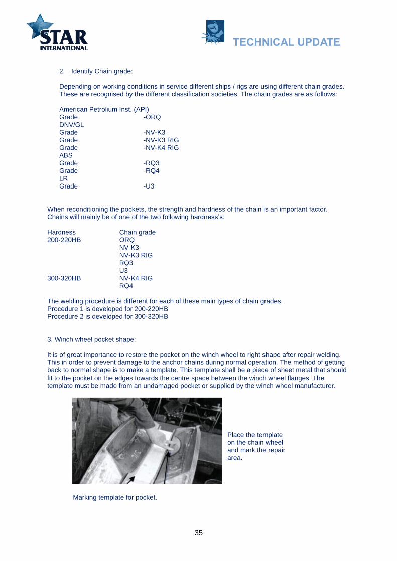
3. Winch wheel pocket shape:
It is of great importance to restore the pocket on the winch wheel to right shape after repair welding. This in order to prevent damage to the anchor chains during normal operation. The method of getting back to normal shape is to make a template. This template shall be a piece of sheet metal that should fit to the pocket on the edges towards the centre space between the winch wheel flanges. The template must be made from an undamaged pocket or supplied by the winch wheel manufacturer.
Place the template on the chain wheel and mark the repair area.
Marking template for pocket.
TECHNICAL UPDATE

36
4. Calculating welding consumable.
By experience we know it is difficult to calculate the correct amount of welding consumable. This is because it is impossible to know in advance how deep it will be required to cut to get rid of the tired material in the pockets. This you will of course know when you are ready to start welding, but to help you on the way we know by experience that each pocket for 76mm (3”) chain requires approx. 8Kg of consumables. There are 5 pockets on each wheel. This value depends on the condition of the pockets, if they have been repaired previously, and how this has been done. To help calculating, one can use a simple formula like the following: Count the areas that require repair on all the winch wheels. Measure the area in cm2. Measure the thickness of the damaged area in cm. Put these values into the following formula: Area in cm2 X Thickness in cm2 X 7,87 (grams) X number of pockets = consumables required.
5. Preparation before welding.
All welding shall be performed under dry conditions. In case of bad weather, the worksite must be covered to obtain the correct conditions.
6. Preparation of base material.
-Cut away all worn base material and old weld metal by air carbon arc gouging (ACA).-Grind the whole area free of grooves, holes, spatter, etc.to at least 1mm below the surface of the ACAgouging, this in order to remove carbon remains.-Examine the entire area for cracks, using dye penetration method or other means. Never usemagnetic powder method for crack detection on stainless steels in combination with steel.- If any cracks, they should be removed by further gouging followed by grinding.- Examine for cracks.
7. Preheating.
Preheating of winch wheels is difficult to perform due to large size of base material and the outdoor welding conditions. The two normally used base materials GS45/3 and GS52/3 have good weldability. The recommended preheating temperature is approx.50-100°C (122-212°F) using oxy acetylene or oxy propane torch. GS 25CrMo 4V is more sensitive to welding and preheating of minimum 150°C (302°F) is recommended. This material is however used on few rigs. Interpass temperature (temperature during welding) should not exceed 250°C (482°F) for neither of the welding procedures.
TECHNICAL UPDATE
37
8. Welding procedure:
Procedure 1.
For use on winch wheels fitted with chains of grades ORQ, NV-K3, NV-K3 RIG, RQ3 and U3. All with chain hardness of approx.200-220HB.
-Welding position should be horizontal or vertical approx.45 deg.-Welding first layer:Use electrode Eutectrode XHD 646 3,2mm (1/8”) Alternative TeroMatec3302*.Amperage: 130-160 Amp DC+.-Weld single beads, do not weave during welding, use previous bead as a heat buffer. Cover thewhole area with first layer.-In case of heavy build up:Use electrode Castolin XHD 646 4,0mm (5/32”).Amperage: 180-230 Amp DC+ for the following layers.-Use template to control that the right thickness is reached. Achieve approx. 1-2mm oversize, beforegrinding.- Check that interpass temperature do not exceed 250°C (482°F).- Grind to remove superfluous material and smoothen the surface. Warning: If the surface is notsmooth after grinding the chain may be damaged when the winch is operating.- Examine the entire area for cracks, using a dye penetrant crack detector. Remember never to usemagnetic penetrant methods for crack detection on stainless steels in combination with carbon steel.
Procedure 2.
For use on winch wheels fitted with chains of grades NV-K4 RIG, RQ4 and U3 all with chain hardness of approx.300-320HB.
-Welding position should be horizontal or vertical approx.45 deg.-Welding first layer:Use electrode Eutec Trode XHD 646 3,2mm (1/8”)Amperage: 130-160 Amp DC+-Weld single beads, do not weave during welding. Use previous bead as a heat buffer. Cover thewhole area with first layer.-In case of heavy build up:Use electrode Eutec Trode XHD 646 4,0mm (5/32”).Amperage: 180-230 Amp DC+ for the following layers.Weld two last layers with electrode EutecTrode 6450 4,0mm (5/32”) Alternative: TeroMatec 3205*Amperage: 150-180Amp DC+.
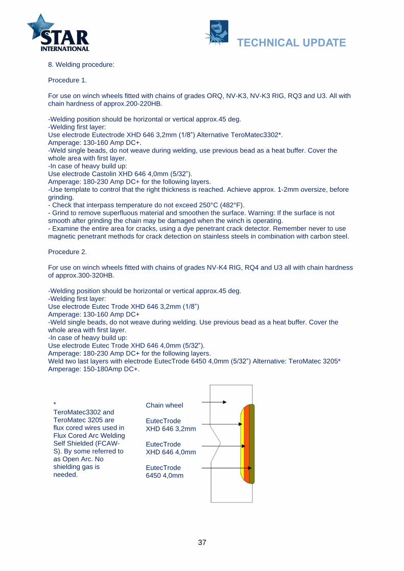
Chain wheel
EutecTrode XHD 646 3,2mm
EutecTrode XHD 646 4,0mm
EutecTrode 6450 4,0mm
* TeroMatec3302 and TeroMatec 3205 are flux cored wires used in Flux Cored Arc Welding Self Shielded (FCAW-S). By some referred to as Open Arc. No shielding gas is needed.
TECHNICAL UPDATE

38
-Use template to control that the right thickness is reached. Achieve approx. 1-2mm oversize, beforegrinding.- Check that interpass temperature do not exceed 250°C (482°F).- Grind to remove superfluous material and smoothen the surface. Warning: If the surface is notsmooth after grinding the chain may be damaged when the winch is operating.- Examine the entire area for cracks, using a dye penetrant crack detector.
9. Consumable
The electrodes recommended for this wear are a type of stainless-steel work hardening austenitic alloy, which hardens under the pressure from the chain. It is of great importance that the overlay is not too hard, as this can result in wear on the links. The electrode has an austenitic structure as welded, and the surface increases in hardness by being transformed to martensitic structure. This work hardening is caused by the chain when the ship / rig is handling her anchors. The high hardness is approx. 1-2mm deep, but can reach deeper on old and heavily deformed overlays. When repair welding takes place this old and hard overlay has to be removed down to the base material. Important: Do not weld on work- hardened, old overlays.
EutecTrode XHD 646 Main Application: Impact Secondary Application: Friction Ideal for buttering layers and rebuilding hardenable alloy steel or 13% manganese steel. -Remarkably easy to weld even in contact-High work-hardening rate-Resistant to hot cracking-Corrosion resistant welds-Thick multipass capability-High metal recovery ~150%-Self-releasing slag-Smooth even beads-Machinable with tungsten carbide tip toolHardness as welded: 190HB 180HV30 Hardness work hardened: 415HB 400HV30
EutecTrode 6450 Main Application: Impact, Friction Secondary Application: Cavitation, Corrosion -Highly resistant to pressure and impact wear-Good work-hardening characteristics-Machinable with standard cutting tools-Allows contact welding-Easy slag removal-Non-magnetic, corrosion-resistant deposit-High metal recovery ~150%Hardness as welded: 240HB 250HV30 Hardness workhardened: 415HB 420HV30
Classification: DIN 8555: E8-UM-200-400-CKZ DIN EN 14700: E Fe 10 AWS A 5.4: ~E 307 - 26 EN ISO: 3581-A: E 18 8 Mn R 53 DIN: W.Nr. 1.4370 DIN 8556: E 18 8 6 Mn R 26
Classification: DIN 8555: E 7-UM-250 KPR DIN EN 14700: E Fe 9 AWS A5.13: E Fe Mn Cr
TECHNICAL UPDATE
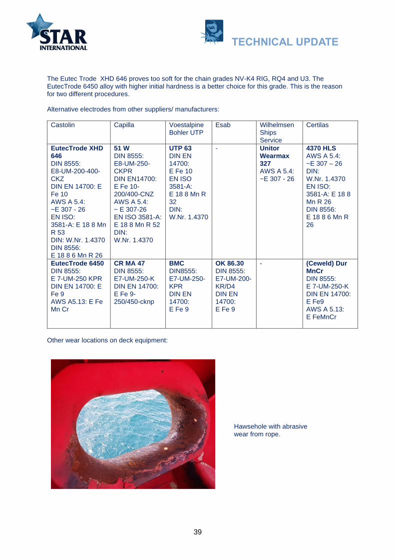
39
The Eutec Trode XHD 646 proves too soft for the chain grades NV-K4 RIG, RQ4 and U3. The EutecTrode 6450 alloy with higher initial hardness is a better choice for this grade. This is the reason for two different procedures.
Alternative electrodes from other suppliers/ manufacturers:
Castolin Capilla Voestalpine Bohler UTP
Esab Wilhelmsen Ships Service
Certilas
EutecTrode XHD 646 DIN 8555: E8-UM-200-400-CKZ DIN EN 14700: E Fe 10 AWS A 5.4: ~E 307 - 26 EN ISO: 3581-A: E 18 8 Mn R 53 DIN: W.Nr. 1.4370 DIN 8556: E 18 8 6 Mn R 26
51 W DIN 8555: E8-UM-250-CKPR DIN EN14700: E Fe 10-200/400-CNZ AWS A 5.4: ~ E 307-26 EN ISO 3581-A: E 18 8 Mn R 52 DIN: W.Nr. 1.4370
UTP 63 DIN EN 14700: E Fe 10 EN ISO 3581-A: E 18 8 Mn R 32 DIN: W.Nr. 1.4370
- Unitor Wearmax 327 AWS A 5.4: ~E 307 - 26
4370 HLS AWS A 5.4: ~E 307 – 26 DIN: W.Nr. 1.4370EN ISO:3581-A: E 18 8Mn R 26DIN 8556:E 18 8 6 Mn R26
EutecTrode 6450 DIN 8555: E 7-UM-250 KPR DIN EN 14700: E Fe 9 AWS A5.13: E Fe Mn Cr
CR MA 47 DIN 8555: E7-UM-250-K DIN EN 14700: E Fe 9-250/450-cknp
BMC DIN8555: E7-UM-250-KPR DIN EN 14700: E Fe 9
OK 86.30 DIN 8555: E7-UM-200-KR/D4 DIN EN 14700: E Fe 9
- (Ceweld) Dur MnCr DIN 8555: E 7-UM-250-K DIN EN 14700: E Fe9 AWS A 5.13: E FeMnCr
Other wear locations on deck equipment:
Hawsehole with abrasive wear from rope.
TECHNICAL UPDATE
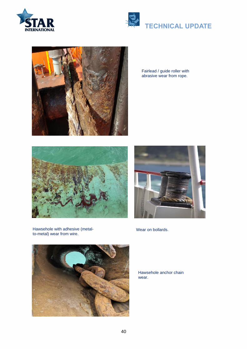
40
Fairlead / guide roller with abrasive wear from rope.
Hawsehole with adhesive (metal-to-metal) wear from wire.
Wear on bollards.
Hawsehole anchor chain wear.
TECHNICAL UPDATE

41
Engine parts
Working environment of Exhaust valves is extremely severe, the highest working temperature can reach to 800-900℃(1472-1652ºF). Engine valve will generate and bear huge shock load when it connects with valve seat. It also needs to bear high speed washing from flue gas. In this harsh working environment, engine valve will always meet situation of deformation, corrosion, burning loss and seat wear. So, Corrosion, Heat and Impact in combination.
1. Machine preparationAlign the spindle in a lathe and turn a suitably wide and deep groove in the hardened face to removeall old stellite down to clean, pure base material. Make room for at least two layers of weld metal, inorder that the second (top) layer shall be near to pure weld metal with as little as possible of elementsfrom base material mixed into it. Grove should have rounded inside corners to avoid slag inclusions.The use of crack indicator is very important at this stage in order that the weld is not put on top ofundiscovered crack in the base material.
2. Weld preparationWelding should as far as possible be carried out in the horizontal position. A suitable jig should beprepared, holding the spindle in a tilted position allowing it to be rotated.
2. Weld preparationWelding should as far aspossible be carried out inthe horizontal position. Asuitable jig should beprepared, holding thespindle in a tilted positionallowing it to be rotated.
Exhaust valves can be made from different types of metals. High-grade stainless steel is often used. Along the rim, there will be an inlay of Stellite. This is a trade name. The alloy consists mostly of cobalt (Co) that is wear resistant at high temperature. Despite this, the wear and tear gradually do its work and leakages and blowholes start to develop.
Conical surface with cobalt inlay
TECHNICAL UPDATE

42
3. PreheatingPreheat the valve head evenly to 50– 200ºC (122-392ºF) and maintain this temperature duringwelding. NB. Preheating temperature depending on type of alloy in the valve.
4. WeldingElectrodes should be dried at 250ºC (482ºF) for 1 hour prior to use. Weld using + polarity to theelectrode holder and an amperage of approximately 110 Amp. Keep the arc short and hold theelectrode as near as possible to 90º to the work piece. In order to minimise heat effects, the weldingshould be done in stages. Place the first bead towards the outer side of the groove, and do about onethird of the circumference. Then start at the opposite side and do the second bead so it finishes wherethe first one started. Finally do the third, starting where the first one finished. For large diameterspindles, the bead should be done in four parts.
Grind the starting and stopping point of each bead. Also grind the bead itself to remove possible slag and spatter, in order to obtain a smooth transition between beads. Control the temperature adjacent to the welding zones and do not start the next bead until the base metal has regained the correct temperature.
First layer or buffer layer.
Second layer or top layer.
Put the first beads towards the outer side of the groove.
Each layer can consist of several beads.
TECHNICAL UPDATE

43
Type of electrode to use to be according to: DIN 8555: E 20-UM-250/300-CRTZ DC DIN EN 14700: E Co1 AWS A5.13: ECoCr-E
DC+ 3,2mm (1/8”) 70-120 Amp Cobalt (Co) Rest Chromium (Cr) 20% Wolfram (W) 15% Nickel (Ni) 10% Manganise (Mn) 1% Silicon (Si) 0,8% Ferrum (Fe 2%) Carbone (C) 0,1% Resistance to thermal shock Good resistance to oxidation Hot crack-resistant Good work-hardening characteristics Hardness ~250 HV30 (as deposited) ~440 HV30 (work-hardened) 25HRc -42HRc Machinable
Castolin: EutecDur 9025N (DIN EN 14700: ECo1, AWS A5.13: ECoCr-E, DIN8555: E20-UM-300-CKTZ) UTP Celsit 721 (DIN EN 14700: ECo1, AWS A5.13: ECoCr-E, DIN8555: E20-UM-300-CKTZ) Wilhelmsen Ships Service: Unitor Impact -329S (DIN 8555: E 20-UM-250-CRTZ)
6. Final machiningAfter cooling, machine to correct tolerances, use tool bit quality H1 or K10 with negative 4º cuttingangle, low turning speed and fine feeding.
NB. Newer designs valves can be made of nimonic metal. Nimonic is a registered trademark of Special Metals Corporation that refers to a family of nickel-based high-temperature low creep superalloys. Nimonic alloys typically consist of more than 50% nickel and 20% chromium with additives such as titanium and aluminium.
Other application for use of this type of electrodes onboard: Pump parts, Valve parts and Rocker arms.
5. CoolingWhen the top layer iscompleted, the spindleshould be immersed ininsulating material or drysand in order to ensureslow cooling.
TECHNICAL UPDATE

44
Ships with special wear problems
Bulk carriers
Bulk carrier, bulker is a merchant ship specially designed to transport unpackaged bulk cargo, such as grains, coal, ore, steel coils and cement, in its cargo holds. Today, bulk carriers make up 21% of the world's merchant fleets. Bulk carriers can be gearless (dependent upon terminal equipment) or geared (having cranes integral to the vessel). Bulk cargo can be very dense, corrosive, or abrasive.
Geared bulk carriers are typically in the handysize to handymax size range although there are a small number of geared panamax vessels, like all bulk carriers they feature a series of holds covered by prominent hatch covers. They have cranes, derricks or conveyors that allow them to load or discharge cargo in ports without shore-based equipment. This gives geared bulk carriers flexibility in the cargoes they can carry and the routes they can travel.
A self-discharger (or self-unloader) is a ship that is able to discharge its cargo using its own gear. The most common discharge method for bulk cargo is to use an excavator that is fitted on a traverse running over the vessel's entire hatch, and that is able to move sideways as well. Lake freighters on the Great Lakes use conveyor-based unloading gear to empty funnel-shaped holds from the bottom, lifting the bulk cargo onto a boom.
TECHNICAL UPDATE

45
Excavator bucket
An excavator bucket is mainly exposed to two types of wear: sliding abrasive wear, and impact wear.
When handling rocks or gravel, it’s usually a mix of both types. Bucket’s structure can in some cases be made of a relatively mild steel, such as A36, grade 50, A514 or S355. If exposed to abrasive materials, the service life will be short and costs for repair and downtime will be high. To increase service life, the mild steel buckets can be “beefed up” with wear-resistant components – a wear
package for protection (wear Strips can be used inside and outside of excavator and loader buckets).
This kind of bucket has a lot of deadweight in the structure due to the combination of mild steel and additional wear parts. A bucket with all of its main components – floor, shell, side sheets, cutting edge, side cutters, cheek plates, wear bars and wear plates – made of a wear-resistant steel such as for example Hardox 450 will be both strong and light. It will also outlast buckets with lower-grade steel several times.
MMAW Electrodes for Bucket lips and teeth rebuilding
Type of Tooth base material
Build-up material Dirt or clay For sand For rock, slag and dirt
Abrasion Severe Abrasion Abrasion and Impact
Manganese steel
DIN 8555:
E7-UM-250-KP
DIN EN 14700: E Fe9
Alternative:
DIN 8555:
E7-UM-200-KP
DIN EN 14700: E Fe9
DIN 8555:
E 10-UM-60-GRZ
DIN EN 14700: E Fe14
DIN 8555:
E 10-UM-60-GR
DIN EN 14700: E Fe15
Alternative:
DIN 8555:
E 10-UM-65-GRZ
DIN EN 14700: E Fe16
DIN 8555:
E 10-UM-45-GPZ
DIN EN 14700: E Fe14
Alternative:
DIN 8555:
E 10-UM-50-GPZ
DIN EN 14700: E Fe6
Alternative:
DIN 8555:
E 10-UM-60-GRZ
DIN EN 14700: E Fe14 Carbon or alloy steel
DIN 8555:
E 1-UM-350-GP
DIN EN 14700: E Fe1
Austenitic consumables (AWS 307 or AWS 309) shall always be used for welding manganese steel adaptors to Hardox cutting edges.
TECHNICAL UPDATE

46
Hard facing Patterns
Selection of the proper hard facing alloy and preparation of the workpiece are not enough to maximize the service life of a part. The pattern used to make the overlay must also be considered, as it too, will have a bearing on how long the part will last. There are times when putting less hard facing on a surface is better than covering the entire surface. There are a number of ways that stringer bead patterns are used depending on the service conditions of the component.
Sever abrasion
To counter severe abrasion, the hardfacing should be continuous across the whole of the surface concerned. This ensures that there is no contact between the external element and the base metal. In most cases, the weld beads are oriented in the same direction as the flow, thus allowing continuous passage of material.
Low or moderate abration
In case of low or moderate abrasion (without impact), surfacing may be limited to separated parallel beads. Spacing of the beads is a key factor that depends directly on the size of the abrasive. In case of high abrasion, the space between the beads should be reduced.
For Dirt, Clay or Sand plase beads perpendicular to material flow.
For Rock or Slag place beads parallel to material flow.
TECHNICAL UPDATE

47
For both Rock, Sand or Dirt use waffle pattern.
This type of pattern is widely used to combat abrasion involving large and small abrasives (e.g. sand with gravel and rock). The bead pattern causes the fine abrasive to lodge in the interstices, thus protecting the base metal from the larger abrasives (self- protection by clogging).
Spot welds (Low or moderate abrasion)
Spot welds is used when the base metal is sensitive to the heat input generated by the welding (e.g. manganese steels). The welding process implies starting the surfacing in the centre and working outwards. This will restrict the welding stresses and distribute them around the part in question.
The interval between the spots depends on the size of the abrasive. The finer the abrasive, the smaller the distance between spots.
TECHNICAL UPDATE

48
Track way and crane wheels
Geared bulk carriers crane will in some cases have a rail trackway and crane wheels that can be in need of hard facing.
Manganese Steel Carbon Steel
1.Grind off all work-hardened and fatigued
base metal.
2. Weld using:
DIN 8555: E 7-UM-200-KP
Weave beads approx.19mm (3/4") wide.
Skip weld to prevent build-up of interpass
temp. Do not allow interpass temp. to
exceed 260°C (500°F). Peen each bead.
3. Finish grind.
1. Grind off work-hardened and
fatigued base metal.
2. Preheat to 425°C (800°F).
3. Weld using:
DIN 8555: E 1-UM-250
Alternative:
DIN 8555: E 1-UM-350-GP
Weave beads. Overbuild to
allow for finish grinding.
4. Post heat 600°C (1100°F)
Cover for slow cooling.
Crane wheels. Weld using electrode: DIN 8555: E 2-UM-55-G A preheat between 200-350°C (392-662°F) is necessary to prevent cracking with interpass temperatures of up to 400°C (752°F) in situations of high restraint and/or heavy thicknesses. After welding the component should be covered and slowly cooled. The deposited weld metal is not machinable by conventional methods although the deposit can be shaped by grinding.
TECHNICAL UPDATE

49
Wear plates
To the extent possible vessels will make use of wear plates. The fastening of the plates can be done mechanically or welded on to the part in question. Hard facing welding of parts is more time consuming and will if not done properly and according to procedure give undesirable side effects.
Consumables for joining and protection of the joints
S
1) Joining of wearplates
2) Protection of joints
Wear resistant plates (Hardox*)
Composite wear plates (or hard faced plates)
A 5.4: ~E 307 - 26 EN ISO 3581-A: E 18 8 Mn R 53 DIN: W.Nr. 1.4370 DIN 8556: E 18 8 6 Mn R 26 Alternative: AWS A 5.11: E NiCrFe-3 EN ISO 14172: E Ni 6082 (NiCr20Mn3Nb) DIN: W.Nr. 2.4648 DIN 1736: EL-NiCr19Nb
AWS A 5.13: E FeCr-E4 DIN EN ISO 14700: E Fe16 DIN 8555: E 10-UM-65-Z
AWS A 5.13: E Fe5-R DIN EN ISO 14700: E Fe4 DIN: W.Nr.1.3348 DIN 8555: E 4–UM 60(65W)-ST
TECHNICAL UPDATE

50
There are a large number of suppliers of wear plates. As an example: below find Vautid 100. It is a composite iron base chromium carbon alloy meant for severe abrasion and moderate impact with 62 HRC. There is a large area of application. The base material is structural steel with a 3 to 20mm hard surfacing layer depending on form of delivery. The plates can only be cut by the plasma cutter onboard.
TECHNICAL UPDATE

51
Hardox steel
Hardox steel is typically used onboard dredgers, bulk carriers and cement carriers that experience abrasive wear from the cargo they are processing and carrying. Often, a Hardox wear plate will be welded to a plain carbon steel structure only in the areas that experience abrasive wear. Since wear does occur, wear plates need to be replaced frequently, which makes this a very common welding application.
There are a number of different types of Hardox steel, ranging from Hardox Hi Temp, Hi Tuf, 400, 450,500,550, 600 and Extreme. The number indicate the approximate Brinell Hardness (HB)*. They are very wear resistant and contain from 0.25 to 0.80% Molybdenum (Mo), 0.10 to 2.5% Nickel (Ni), 0.10 to 1.5% Chromium (Cr) all depending on type of alloy.
To avoid weld cracking, the joint needs a welding procedure that need to be followed rather strictly. It is important to use an electrode with lower strength than the Hardox base metal for the root and filler passes, and then hard face only on the capping pass to obtain abrasion resistance of the weld surface.
Preheating and interpass temperature (temperature during welding) depend on type of Hardox and the plate thickness.
Root run Filler pass(es)
Capping pass
TECHNICAL UPDATE

52
Maximum preheating and interpass temperature
Hardox Hi Temp 300°C (572°F)
Hardox Hi Tuf* 300°C (572°F)
Hardox 400 225°C (437°F)
Hardox 450 225°C (437°F)
Hardox 500 225°C (437°F)
Hardox 550 225°C (437°F)
Hardox 600 225°C (437°F)
Hardox Extreme 100°C (212°F)
Type of electrodes: It is important to use an electrode with lower strength than the Hardox base metal for the root and filler passes, and then hard face only on the cover pass to obtain abrasion resistance of the weld surface. Unalloyed and low-alloyed electrodes with a maximum tensile strength of 500 MPa (72519 psi) are generally recommended for Hardox steel in general. Electrodes of higher strength max. 900 MPa (130534 psi) may be used for Hardox 400 and 450 in the thickness range 0.7 – 6.0 mm (0.028” – 0.236”).
A better solution to consider: Consumables of austenitic stainless steels can be used for welding all types of Hardox. They allow welding at room temperature 5 – 20°C (41 – 68 °F) without preheating, except for Hardox 600 and Hardox Extreme. The manufacturer of Hardox recommends giving first preference to consumables in accordance with AWS 307 and second preference to those in accordance with AWS 309. These types of consumables have a yield strength of up to approximately 500 MPa (72519 psi) in all weld metal. The AWS 307 type can withstand hot cracking better than AWS 309. Manufacturers seldom specify the hydrogen content of stainless-steel consumables, since hydrogen does not affect the performance as much as it does in unalloyed and low-alloyed consumables.
Electrode classification for joining and fastening of Hardox plates:
A 5.4: ~E 307 - 26 EN ISO 3581-A: E 18 8 Mn R 53 DIN: W.Nr. 1.4370 DIN 8556: E 18 8 6 Mn R 26
In general, about AWS 5.4 E307 electrodes: Joining of wear plates like Hardox to each other and to their supports. Welding of 14% Mn steel, armour steel, harden able steel and generally all hard-to-weld steels. Joining of stainless steels to carbon steels. Building up of rails and buttering layers before hard facing on 14%Mn steel or on steels of unknown composition or on carbon steels. An important electrode to have onboard a vessel.
Interpass temperatures up to approx.
400°C (752°F) can be used in certain
cases for Hardox Hi Tuf.
TECHNICAL UPDATE

53
Before tack welding, it is important to maintain a root opening between base plates not exceeding 3 mm (1/8”). Aim for as uniform a gap size along the joint as possible. Also, avoid weld start and weld stops in highly stressed areas. Make multiple smaller weld beads maintaining the base materials interpass temperature as mentioned above. If possible, the start and stop procedures should be at least 50 –100 mm (2” – 4”) from a corner. When welding to the edge of plates, a runoff weld tab (steel plate) would be beneficial.
Use a symmetrical weld sequence.
If the weld joint is located in an area with the expectation of high wear, one can employ hard facing with special consumables to increase the wear resistance of the weld metal.
Electrode classification for hard surfacing:
AWS A 5.13: E FeCr-E4 EN ISO 14700: E Fe16 DIN 8555: E 10-UM-65-Z
3mm (1/8”) max
3mm (1/8”) max
TECHNICAL UPDATE

54
Hardox 500 plates welded into a steep shaft to stop wear.
Original shape
The gravel has eaten away the top part of the plate.
Flow direction
Also the weld keeping the plates in place have been worn away
TECHNICAL UPDATE
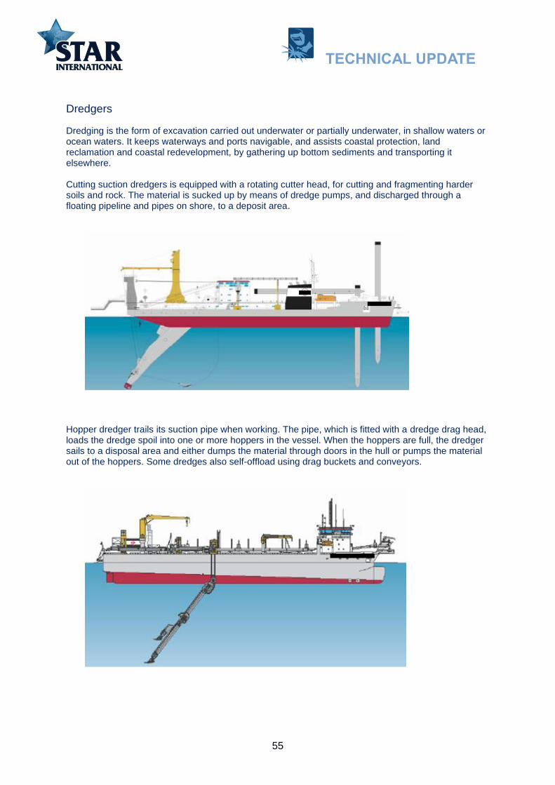
55
Dredgers
Dredging is the form of excavation carried out underwater or partially underwater, in shallow waters or ocean waters. It keeps waterways and ports navigable, and assists coastal protection, land reclamation and coastal redevelopment, by gathering up bottom sediments and transporting it elsewhere.
Cutting suction dredgers is equipped with a rotating cutter head, for cutting and fragmenting harder soils and rock. The material is sucked up by means of dredge pumps, and discharged through a floating pipeline and pipes on shore, to a deposit area.
Hopper dredger trails its suction pipe when working. The pipe, which is fitted with a dredge drag head, loads the dredge spoil into one or more hoppers in the vessel. When the hoppers are full, the dredger sails to a disposal area and either dumps the material through doors in the hull or pumps the material out of the hoppers. Some dredges also self-offload using drag buckets and conveyors.
TECHNICAL UPDATE

56
To the extent possible the dredgers will make use of wear plates. The fastening of the plates or bars can be done mechanically or welded on to the part in question. Hard surfacing welding of parts is more time consuming and will if not done properly and according to procedure give undesirable side effects.
Wear and tear on pump casings and impeller
Depending on type of vessel, wear resistant materials are chosen for the equipment in contact with soil, this allows for longer service life of the components:
Double walled dredge pumps, with hard cast-iron pump housing, special alloy impellers and wear plates are used for cutter dredgers, and the large hopper dredgers. On other vessels cast steel single walled pumps are installed.
Dredge pipes are lined with Ni-Hard*, or made of alloys with high resistance to abrasion for cutter dredgers and pipes in the pump room of large hopper dredgers (sometime in combination with FEDUR**). On other hoppers cast steel and rolled mild steel pipes are used.
Cutterheads designed for low maintenance: liners protect critical parts. The teeth system allows for easy and quick maintenance.
Drag heads protect with domite wear plates.
Rubber hoses: equipped with liners or special design.
* Ni- Hard= Cr 1,4% - 28% abrasive iron for low and high stress abrasion 400 to 750 Brinell.** FEDUR= Composite steel of two layers. One layer with high weldability. The other hard carbon steel alloy of 910 HV (approx.66HRC)
Suction mouth of a cutter dredger with domite laminated wear plates (700 HB- 63HRC). Domite is a cast high carbon-molybdenum white iron on a backing plate of mild steel.
TECHNICAL UPDATE

57
The following consumable chart gives suggested stick electrodes for Manual Metal Arc Welding (MMAW) according to DIN 8555 classification. The same chart can be used for Wire Welding process and tubular wires (metal cored or flux cored). Some of the symbols will however be different. An example:
An electrode according DIN 8555 for MMAW will read: E 10-UM-45-GPZ
A tubular wire according DIN 8555 for wire welding will read: MF 10-GF-45-GPZ
For Pump casings, Pump impellers, Side plates
Dredge pump casings can be made from cast iron, manganese steel or carbon steel. Manganese and cast steel pumps can be rebuilt. Rebuilding of cast iron pumps must be avoided.
Classification Build-up/buttering
Base metal
Carbon steel
Build-up/buttering
Base metal
Manganese steel
Hard facing
DIN 8555: E 1-UM-250
E 1-UM-350-GP
E 7-UM-250-KP
E 7-UM-200-KP
E 10-UM-45-GPZ
E 10-UM-60-GR
E 10-UM-65-GRZ
E 10-UM-50-GPZ
E 10-UM-60-GRZ
Electrode Coated
Tubular wire, metal cored or flux cored Filled
Pump casings: Severe abrasion hard face using: E 10-UM-65-GRZ or E 10-UM-60-GR. Moderate abrasion and moderate impact hard face using: E 10-UM-50-GPZ or E 10-UM-45-GPZ.
Pump impellers: Severe worn manganese steel wanes rebuilding using: E 7-UM-200-KP. Severe worn carbon steel wanes rebuilding using: E 1-UM-250 or E 1-UM-350-GPSevere abrasion hard face with E 10-UM-60-GR or E 10-UM-65-GRZModerate impact and abrasive wear hard surface using: E 10-UM-45-GPZ or E 10-UM-50-GPZ.
Side plates: Rebuild worn seat areas of carbon steel using: E 1-UM-250 Rebuild worn seat areas of manganese steel using: E 7-UM-200-KP Hard face with: E 10-UM-60-GR, E 10-UM-65-GRZ or E 10-UM-60-GRZ.
TECHNICAL UPDATE

58
For Dredge Cutters head and Teeth
Classification Build-up/buttering
Base metal
Carbon steel
Build-up/buttering
Base metal
Manganese steel
Hard facing
DIN 8555: E 1-UM-250
E 1-UM-350-GP
E 7-UM-250-KP
E 7-UM-200-KP
E 10-UM-60-GR
E 10-UM-65-
GRZ
E 10-UM-60-
GRZ
There are various tooth and cutting-edge systems on the market, each with its own advantages and disadvantages. They are all based on the principle that it must be possible to quickly replace the parts that are subject to heavy wear.
For Dredge Bucket Lips
Classification Build-up/buttering
Base metal
Hard facing
DIN 8555: - E 10-UM-45-GPZ
E 10-UM-60-GR
E 10-UM-65-GRZ
E 10-UM-50-GPZ
E 10-UM-60-GRZ
Depending on base metal build up with recommended consumable. Hard face with: E 10-UM-60-GR or E 10-UM-60-GRZ.
Cutter head. The flared points overlaid with Wo carbides.
Severe abrasion: E 10-UM-60-GR Abrasive wear and moderate impact: E 10-UM-50-GPZ or E 10-UM-60-GRZ
TECHNICAL UPDATE
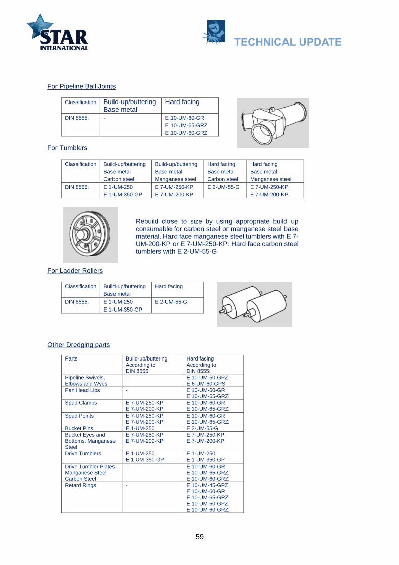
59
For Pipeline Ball Joints
Classification Build-up/buttering Base metal
Hard facing
DIN 8555: - E 10-UM-60-GR
E 10-UM-65-GRZ
E 10-UM-60-GRZ
For Tumblers
Classification Build-up/buttering
Base metal
Carbon steel
Build-up/buttering
Base metal
Manganese steel
Hard facing
Base metal
Carbon steel
Hard facing
Base metal
Manganese steel
DIN 8555: E 1-UM-250
E 1-UM-350-GP
E 7-UM-250-KP
E 7-UM-200-KP
E 2-UM-55-G E 7-UM-250-KP
E 7-UM-200-KP
For Ladder Rollers
Classification Build-up/buttering
Base metal
Hard facing
DIN 8555: E 1-UM-250
E 1-UM-350-GP
E 2-UM-55-G
Other Dredging parts
Parts Build-up/buttering According to DIN 8555:
Hard facing According to DIN 8555:
Pipeline Swivels, Elbows and Wyes
- E 10-UM-50-GPZ E 6-UM-60-GPS
Pan Head Lips - E 10-UM-60-GR E 10-UM-65-GRZ
Spud Clamps E 7-UM-250-KP E 7-UM-200-KP
E 10-UM-60-GR E 10-UM-65-GRZ
Spud Points E 7-UM-250-KP E 7-UM-200-KP
E 10-UM-60-GR E 10-UM-65-GRZ
Bucket Pins E 1-UM-250 E 2-UM-55-G
Bucket Eyes and Bottoms. Manganese Steel
E 7-UM-250-KP E 7-UM-200-KP
E 7-UM-250-KP E 7-UM-200-KP
Drive Tumblers E 1-UM-250 E 1-UM-350-GP
E 1-UM-250 E 1-UM-350-GP
Drive Tumbler Plates. Manganese Steel Carbon Steel
- E 10-UM-60-GR E 10-UM-65-GRZ E 10-UM-60-GRZ
Retard Rings - E 10-UM-45-GPZ E 10-UM-60-GR E 10-UM-65-GRZ E 10-UM-50-GPZ E 10-UM-60-GRZ
Rebuild close to size by using appropriate build up consumable for carbon steel or manganese steel base material. Hard face manganese steel tumblers with E 7-UM-200-KP or E 7-UM-250-KP. Hard face carbon steel tumblers with E 2-UM-55-G
TECHNICAL UPDATE

60
Cement carriers
Cement cargos account for about 5% of the world’s dry bulk trade. These cargos are typically shipped in bulk, and many bulk carriers are able to transport cement. A cement carrier will be a single-skin or double-skin bulk carrier provided with a cement loading and discharging plant. Traditionally, cement carriers are loaded by gravity or by pressure from silo.
Pneumatic cement carriers. A more sophisticated way to load or discharge is to deploy a special type of vessel equipped with own compressors and pumps: self-discharging, pneumatic cement carriers. This type uses the principle that when air is pumped through a cement cargo, it acts as if it were liquid. In this way, cement can be loaded easily and, while discharging, can be moved readily to a central trunk at the bottom of holds.
Mechanical cement carriers. Screw conveyors and conveyor chains are also in use both for mechanical loading and unloading of cement carriers and for the transfer of cargo between ships and shore-based facilities. Screw conveyors are designed to handle fluidisable powdery cargoes such as cement, fly ash and limestone powder under tough conditions. The horizontal screw conveyor distribution arrangement ensures cement is loaded evenly into a ship’s holds, both longitudinally and transversely. The vertical screw conveyor is used for elevating the cement above deck level.
Conveyour screws
TECHNICAL UPDATE

61
Conveyor screws
Conveyor chains
MMAW Stick / Electrodes and Self-Shielded (FCAW-S) wire (Open Arc) Hard facing Comparison Chart
The charts are based on resemblance with regards to classification. Please note that the classifications alloy groups can have large variations. This can also be the case for mechanical values (hardness) and suitability. The comparison has not taken into account if the consumable is high or normal recovery type or if it can be used in different positions. It is therefore advisable to contact the manufacturer for finer details and for last updates.
Edge surface with: DIN EN 14700: EZ Fe20 DIN 8555: E 21-UM-65-G Alternative oxy-acetylene rod consisting of nickel based alloy with tungsten carbides: DIN EN 14700: T Ni20 DIN 8555: G-21-UM-50 CG
Build up worn areas with:AWS A 5.4: ~E 307 - 26 EN ISO 3581-A: E 18 8 Mn R 53 DIN: W.Nr. 1.4370 DIN 8556: E 18 8 6 Mn R 26
Hard facing with:AWS A 5.13: E FeCr-A1 DIN EN 14700: E Fe14 DIN 8555: E10-UM-60-GRZ Alternative: AWS A 5.13: E FeCr-E4 DIN EN 14700: E Fe16 DIN 8555: E 10-UM-65-Z
TECHNICAL UPDATE

62
MMAW Electrodes Hard facing Comparison Chart 1
Classification Build-up
(Ferrite/Bainite)
Adhesive (Metal-to-metal) Metal to Earth
Austenitic and Eutectic
Carbides
Martensite Martensite/ Austenite
Tool steel (Austenite)
DIN 8555: E 1-UM-250
E 1-UM-350-GP
E 2-UM-55-G
E 6-UM-60-GPS E 4-UM-60-SZ
E 10-UM-60-GRZ
DIN EN 14700: EFe1 EFe1 EFe2 EFe6 EFe4 EFe14
LINCOLN ELECTRIC
Wearshield BU
Wearshield BU30
Wearshield MM
Wearshield MI
Wearshield T&D
Wearshield ME
STOODY (ESAB)
Build-up (DIN 8555:
E 1-UM-250-P
DIN EN 14700: EFe1)
Build-up LH
(DIN 8555: E 1-UM-250-P
DIN EN14700:EFe1)
Selfhardening (DIN 8555: E 6-
UM-55-GP DIN EN 14700:
EFe8)
35 (DIN 8555: E 10-UM-55-G
DIN EN14700:EFe14)2134CTS
(DIN 8555: E 10-UM-60-G
DIN EN14700:EFe14)
VOESTALPINE BOHLER UTP
Dur 250 (DIN 8555:
E 1-UM-250
DIN EN 14700: EFe1)
DUR 350 (DIN 8555:
E 1-UM-350
DIN EN 14700: EFe1)
Dur 600 (DIN 8555: E 6-
UM-60 DIN EN 14700:
EFe8)
UTP 690 (DIN 8555: E 4-UM-60-
ST DIN EN 14700: EFe4)
Lerduit 61 (DIN 8555: E 10-UM-60-
GRZDIN EN 14700:
EZFe14)
ESAB OK Weartrode
30HD Former:
OK 83.29 (DIN 8555:
E 1-UM-300
DIN EN 14700: EFe1)
OK Weartrode
30 Former:
OK 83.28 (DIN 8555:
E 1-UM-350
DIN EN 14700: EZFe1)
OK Weartrode
50 Former : OK 83.50
(DIN 8555: E 6-UM-55
DIN EN 14700: EZFe2)
OK Weartrode 55HD
Former: OK 84.58
(DIN 8555: E 6-UM-55-G
DIN EN 14700: EZFe6)
OK Tooltrode
60 Former:
OK 85.65 (DIN 8555: E 4-UM-60
DIN EN 14700: EFe4)
OK Weartrode
60T Former:
OK 84.78 (DIN 8555:
E 10-UM-60-GZ
DIN EN 14700:
EZFe14)
MCKAY (ITW)
Hardalloy 32
Hardalloy 58
Hardalloy 58/61/600
Hardalloy 61
Hardalloy 140
CERTANIUM 283FC
(293,723)
281FC, 246FC
267 221
(211)
246
All- State welding products (Esab)
Wear Arc 3 IP
Wear Arc 4 IP
Wear Arc 5 IP
Wear Arc 40
RANKIN BU/700 Ranite
Bx,B Ranite G,D
(Ranite31,Ranite A)
Ranite 4
Ranite35
Ranite j (1)
TECHNICAL UPDATE

63
MMAW Electrodes Hard facing Comparison Chart 1 (Continue)
Classification Build-up
(Ferrite/Bainite)
Adhesive (Metal-to-metal) Metal to Earth
Austenitic and Eutectic
Carbides
Martensite Martensite/ Austenite
Tool steel (Austenite)
DIN 8555: E 1-UM-250 E 1-UM-350-GP
E 2-UM-55-G
E 6-UM-60-GPS E 4-UM-60-SZ
E 10-UM-60-GRZ
DIN EN 14700: EFe1 EFe 1 EFe2 EFe6 EFe4 EFe14
CASTOLIN EUTECTIC (Messer)
EutecTrode 2B
(DIN 8555: E 1-UM-
300P DIN EN 14700: EFe1)
EutecTrode N 102
(DIN 8555:E 6-UM-55-G)
EutecTrode 6
(DIN 8555:E 4-UM-60-
ST)
EutecTrode N6006
(DIN 8555:E 10-UM-60-
GR)
HOBART (ITW)
Hardalloy 32
WELDING ALLOYS
Hardface 250-E
(DIN EN14700:E Fe1)
Hardface LE
(DIN EN 14700: T Fe8)
Hardface AR-E
(DIN EN 14700: E Fe4)
STULTZ SICKLES
Special alloy
Ultra Hard 60
WELDMOLD Polytrode HD 515
Polywear 358
METRODE (LINCOLN ELECTRIC)
Met-hard 350
(DIN 8555: E 1-UM-400-GPDIN EN14700:E Fe1)
Met-hard 650
Met-hard 650R
(DIN 8555: E 6-UM-60-GP
DIN EN 14700: E Fe2)
Met-hard 750TS
(DIN EN 14700: E Fe4)
Met-hard 950
(DIN 8555: E 10-UM-60-
GRDIN EN 14700: E Fe9)
SOUDOMETAL Tenasoud 105
(DIN 8555: E 1-UM-
300)
SELECTARC HB 25 DIN 8555:
E1-UM-250
HB 40 DIN 8555:
E1-UM-400
HB 60 DIN 8555: E2-UM-60 EN 14700:
E Fe2
TECHNICAL UPDATE
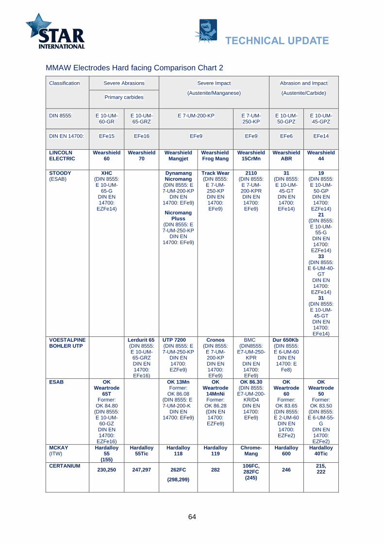
64
MMAW Electrodes Hard facing Comparison Chart 2
Classification Severe Abrasions Severe Impact
(Austenite/Manganese)
Abrasion and Impact
(Austenite/Carbide) Primary carbides
DIN 8555: E 10-UM-60-GR
E 10-UM-65-GRZ
E 7-UM-200-KP E 7-UM-250-KP
E 10-UM-50-GPZ
E 10-UM-45-GPZ
DIN EN 14700: EFe15 EFe16 EFe9 EFe9 EFe6 EFe14
LINCOLN ELECTRIC
Wearshield 60
Wearshield 70
Wearshield Mangjet
Wearshield Frog Mang
Wearshield 15CrMn
Wearshield ABR
Wearshield 44
STOODY (ESAB)
XHC (DIN 8555: E 10-UM-
65-GDIN EN14700:
EZFe14)
Dynamang Nicromang
(DIN 8555: E 7-UM-200-KP
DIN EN14700: EFe9)
Nicromang Pluss
(DIN 8555: E 7-UM-250-KP
DIN EN14700: EFe9)
Track Wear (DIN 8555:
E 7-UM-250-KPDIN EN14700:EFe9)
2110 (DIN 8555: E 7-UM-200-KPRDIN EN14700:EFe9)
31 (DIN 8555: E 10-UM-
45-GTDIN EN14700:EFe14)
19 (DIN 8555: E 10-UM-
50-GPDIN EN14700:
EZFe14)21
(DIN 8555: E 10-UM-
55-GDIN EN14700:
EZFe14)33
(DIN 8555: E 6-UM-40-
GT DIN EN 14700:
EZFe14) 31
(DIN 8555: E 10-UM-
45-GTDIN EN14700:EFe14)
VOESTALPINE BOHLER UTP
Lerdurit 65 (DIN 8555: E 10-UM-65-GRZDIN EN14700:EFe16)
UTP 7200 (DIN 8555: E 7-UM-250-KP
DIN EN14700: EZFe9)
Cronos (DIN 8555:
E 7-UM-200-KPDIN EN14700:EFe9)
BMC (DIN8555:
E7-UM-250-KPR
DIN EN 14700: EFe9)
Dur 650Kb (DIN 8555: E 6-UM-60
DIN EN 14700: E
Fe8)
ESAB OK Weartrode
65T Former:
OK 84.80 (DIN 8555: E 10-UM-
60-GZDIN EN14700:
EZFe16)
OK 13Mn Former:
OK 86.08 (DIN 8555: E 7-UM-200-K
DIN EN14700: EFe9)
OK Weartrode
14MnNi Former:
OK 86.28 (DIN EN 14700: EZFe9)
OK 86.30 (DIN 8555:
E7-UM-200-KR/D4 DIN EN 14700: EFe9)
OK Weartrode
60 Former:
OK 83.65 (DIN 8555: E 2-UM-60
DIN EN 14700: EZFe2)
OK Weartrode
50 Former:
OK 83.50 (DIN 8555: E 6-UM-55-
G DIN EN 14700: EZFe2)
MCKAY (ITW)
Hardalloy 55
(155)
Hardalloy 55Tic
Hardalloy 118
Hardalloy 119
Chrome-Mang
Hardalloy 600
Hardalloy 40Tic
CERTANIUM 230,250 247,297 262FC
(298,299)
282 106FC, 282FC (245)
246 215, 222
TECHNICAL UPDATE

65
MMAW Electrodes Hard facing Comparison Chart 2 (continue)
Classification Severe Abrasions Severe Impact
(Austenite/Manganese)
Abrasion and Impact
(Austenite/Carbide) Primary carbides
DIN 8555: E 10-UM-60-GR
E 10-UM-65-GRZ
E 7-UM-200-KP E 7-UM-250-KP
E 10-UM-50-GPZ
E 10-UM-45-GPZ
DIN EN 14700: EFe15 EFe16 EFe9 EFe9 EFe6 EFe14
All- State welding products (Esab)
Wear Arc 40
Wear Arc Ni-
Manganese
Wear Arc Super WH
Wear Arc 6 IP
RANKIN Ranite 4
Ranite M
Ranmang 1 Ranmang 3 MC
(Ranmang 3)
16
(Ranite D)
(Ranitye J)
Ranite F
CASTOLIN EUTECTIC (Messer)
EutecTrode N6006
(DIN 8555: E 10-UM-60-GR)
EutecTrode N6710
(DIN 8555: E 10-UM-
65-G)N6715
(DIN 8555: E 10-UM-70-GZ)
EutecTrode 6450
(DIN 8555: E 7-UM-250-KPRDIN EN14700:EFe9)
HOBART (ITW)
Hardalloy 140
Hardalloy 118
Hardalloy 148
WELDING ALLOYS
Hardface HC-E
(DIN EN 14700: E Fe15)
Hardface CNV-E
(DIN EN 14700: E Fe16)
Hardface AP-E
(DIN EN 14700: E Fe9)
STULTZ SICKLES
Manganese XL
Universal HF
WELDMOLD Polywear 325
AWS: EFeMn-B
METRODE (LINCOLN ELECTRIC)
Met-hard 1050
(DIN 8555: E 10-UM-
65-GPDIN EN14700:E Fe16)
Work-hard 13MN
(DIN 8555: E 7-UM-200-KP(DIN EN14700:E Fe9)
SOUDOMETAL CoMetMC
SELECTARC HRT 60 EN 14700:
E Fe15
HB 14Mn (DIN 8555:
E7-UM-250-KP
EN 14700: E Fe9
AWS A5.13: ~EFeMn-C)
HB 63 DIN 8555: (E10-UM-60-GRPZEN 14700:
E Fe14)
TECHNICAL UPDATE

66
Self-Shielded (FCAW-S) wire (Open Arc) Hard Facing Comparison Chart
Classification Build- up Ferritic Bainitic
Metal to Metal Martensitic
Metal to Metal Tool steel Martensitic
DIN 8555: MF1-GF-350-GPS MF1-GF-400-GPS MF2-GF-55-GP MF4-GF-60-S
DIN EN 14700: TFe1 TFe1 TFe2 TFe8
Lincoln Lincore 33
Lincore 40-O
Lincore 55
Lincore T&D
Stoody (Esab)
Super Build-up 104-O
105-ORail end 932-O
965-O 102G-O
McKay / Hobart (ITW)
Tube alloy 242-0
Tube alloy 242-O
Tube alloy 258-O/ Armor Wear
Tube alloy 258-O
All- State welding products (Esab)
Wear o Matic 3 Wear O Matic 6 - -
Certanium Alloys
283FC - 281FC
CASTOLIN EUTECTIC (Messer)
Teromatec OA 3010
- Teromatec OA 4415
-
Rankin Industries
Ranomatic BU
Ranomatic 969-O
Ranomatic BX 2,D
-
Stultz Sickles - Stultz Multi Layer 50-S/A
Stultz Multi Layer 50-S/A
-
Welding Alloys Hardface T-O
Hardface P-O
Hardface W-O
Hardface L-O
Classification Sever Impact Austenitic Manganese
Abrasion plus Impact Austenitic and Carbides
Sever Abrasion Primary Carbides
DIN 8555: MF6-GF-45-KP MF7-GF-250-KP :MF6-GF-50-GP MF10-GF-60-CG
DIN EN 14700: TFe9 TFe9 TFe8 TFe15
Lincoln Lincore M Lincore 15CrMn Lincore 50 Lincore 60-0
Stoody (Esab)
Dynamag-O Nicromang-O Plus-
O
110-O 117-O,121-O,134-O,133-O
100HC,101HC-O
McKay / Hobart (ITW)
Tube alloy 218-O
Tube alloy AP-O
Tube alloy 240-O
Tube alloy 255-O
All- State welding products (Esab)
Wear O Matic Nickel Mang
Wear O Matic Super WH
Wear O Matic 12 Wear O Matic 40
Certanium Alloys - 282FC 284FC 247FC
CASTOLIN EUTECTIC (Messer)
TeroMatec 3220
TeroMatec 3302
TeroMatec 4923
TeroMatec 4601
Rankin Industries
Ranomang 1
Ranomang 3
Ranomatic BX-2
Ranomatic R-100HD
Stultz Sickles Stulz Manganese XL-S/A
Stulz No. 1616S/A Stulz No.12S/A
Welding Alloys Hardface TIC-O
Hardface 19/9/6-O
AP-O
Hardface NCWB-O
Hardface CN-O
TECHNICAL UPDATE
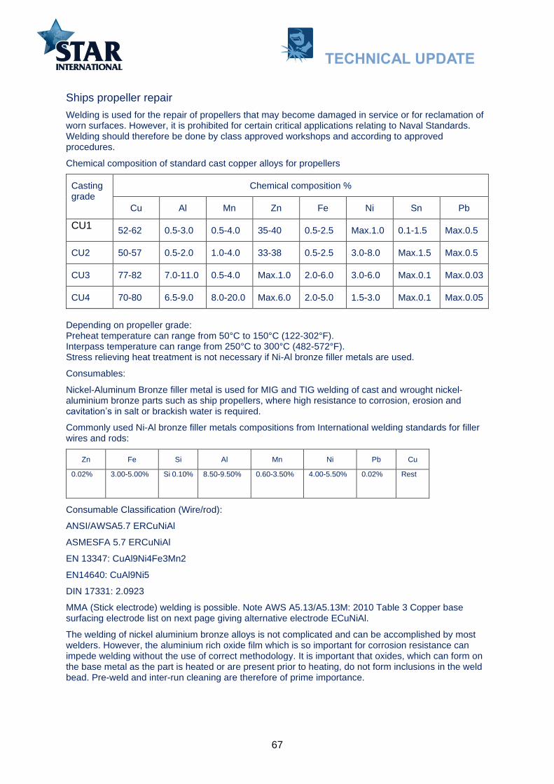
67
Ships propeller repair
Welding is used for the repair of propellers that may become damaged in service or for reclamation of worn surfaces. However, it is prohibited for certain critical applications relating to Naval Standards. Welding should therefore be done by class approved workshops and according to approved procedures.
Chemical composition of standard cast copper alloys for propellers
Casting grade
Chemical composition %
Cu Al Mn Zn Fe Ni Sn Pb
CU1 52-62 0.5-3.0 0.5-4.0 35-40 0.5-2.5 Max.1.0 0.1-1.5 Max.0.5
CU2 50-57 0.5-2.0 1.0-4.0 33-38 0.5-2.5 3.0-8.0 Max.1.5 Max.0.5
CU3 77-82 7.0-11.0 0.5-4.0 Max.1.0 2.0-6.0 3.0-6.0 Max.0.1 Max.0.03
CU4 70-80 6.5-9.0 8.0-20.0 Max.6.0 2.0-5.0 1.5-3.0 Max.0.1 Max.0.05
Depending on propeller grade: Preheat temperature can range from 50°C to 150°C (122-302°F). Interpass temperature can range from 250°C to 300°C (482-572°F). Stress relieving heat treatment is not necessary if Ni-Al bronze filler metals are used.
Consumables:
Nickel-Aluminum Bronze filler metal is used for MIG and TIG welding of cast and wrought nickel-aluminium bronze parts such as ship propellers, where high resistance to corrosion, erosion and cavitation’s in salt or brackish water is required.
Commonly used Ni-Al bronze filler metals compositions from International welding standards for filler wires and rods:
Zn Fe Si Al Mn Ni Pb Cu
0.02% 3.00-5.00% Si 0.10% 8.50-9.50% 0.60-3.50% 4.00-5.50% 0.02% Rest
Consumable Classification (Wire/rod):
ANSI/AWSA5.7 ERCuNiAl
ASMESFA 5.7 ERCuNiAl
EN 13347: CuAl9Ni4Fe3Mn2
EN14640: CuAl9Ni5
DIN 17331: 2.0923
MMA (Stick electrode) welding is possible. Note AWS A5.13/A5.13M: 2010 Table 3 Copper base surfacing electrode list on next page giving alternative electrode ECuNiAl.
The welding of nickel aluminium bronze alloys is not complicated and can be accomplished by most welders. However, the aluminium rich oxide film which is so important for corrosion resistance can impede welding without the use of correct methodology. It is important that oxides, which can form on the base metal as the part is heated or are present prior to heating, do not form inclusions in the weld bead. Pre-weld and inter-run cleaning are therefore of prime importance.
TECHNICAL UPDATE

68
There are a number of ships items made from copper alloys that can be in need of resurfacing by welding. Pump and valve housing, impellers and turbine blades. Very often the type of wear will be the same as for propellers: Cavitation wear. Electrodes according to ANSI/AWSA5.7 ERCuNiAl will be the preferred type.
Ele
ctr
ode b
rands a
ccord
ing
to A
NS
I/A
WS
A5.7
ER
CuN
iAl
TECHNICAL UPDATE

69
Alternative hard facing methods and materials
Ceramics Ceramics can be an alternative help to solve abrasion problems. Ceramic pipes are used in processes where transport of cement, coal, glass particles as well as corrosive and aggressive vapours are exposing equipment to severe abrasive wear.
Ceramic wear plates are used where distribution of large volumes of rough materials causes impact
and strain on the equipment. They are often used in barges that load and unload excavated gravel
and rocks, and for heavy steel scrap handling. Alumina: Chemically very stable material with high resistance to wear with a hardness of about 9 on the Mohs scale*. Density 4 g / cm3. Zirconium oxide: Similar to alumina but has greater resistance to mechanical wear and tear. Density 5.7 g / cm3 Silicon carbide: Has extremely high resistance to mechanical wear and high temperatures. Density 3.2 g / cm3 Tungsten carbide: Very hard and heavy material. Highly resistant to abrasion and acids. Hardness is about 9 on Moh’s scale. Density 15.63 g / cm3. High melting point of 2870°C (5198°F).
* Mohs scale of mineral hardness is a scale characterizing scratch resistance of various minerals through the ability of harder
material to scratch softer material.
Polymer compounds Polymer compounds can in some cases, have better wear properties than weld overlays. Specifically concerning cavitation wear in fluid flow environments. Large surfaces that are worn are also much faster overlaid with polymer compounds than with weld bead overlays.
Thermal spraying Thermal spraying is a method of repairing, reconditioning and refinishing surfaces exposed to extensive adhesive wear and abrasion.
Ceramic tails glued into a shaft (75°). Despite this, the recirculated asphalt (bitumen and gravel) have started the wear process.
TECHNICAL UPDATE

70
SUMMING UP:
WHAT TO CONSIDER BEFORE HARDFACING
NAME OF PART________________________________________________________________
What is the base material chemical composition?
Carbon steel
Low alloy steel
Manganese steel
Stainless steel
What is the wear problem?
Abrasion
If abrasive wear check out the following:
Type of product causing the wear: ____________________________________________
Hardness of the particles in the product: ________________________________________
Size of the particles: _______________________________________________________
Edge sharpness: _________________________________________________________
Velocity: ________________________________________________________________
Angle of introduction towards the substrat______________________________________
Ambient temperature ______________________________________________________
Impact
Adhesive
Cavitation
Heat
Corrosion
Is there a combination of wear problems? _____________________________________________
Which is the most important? _______________________________________________________
Is there old hard facing layer on the part which needs to be removed? _______________________
Is preheat necessary? ____________________________________________________________
What about cooling rate? __________________________________________________________
What position is needed for welding? ________________________________________________
Is build up layer and buttering layer necessary before hard facing? _________________________
Any particular welding sequence to be used? __________________________________________
What method or process is best to use or available? MMAW TIG Wire Welding
What welding consumable to consider for build-up layer and buttering? _____________________
_____________________________________________________________________________
What welding consumable to consider for hard facing? __________________________________
Make simple sketch of part/ location/wear problem
TECHNICAL UPDATE