welding of duplex stainless steel.pdf
TRANSCRIPT
7/30/2019 Welding of Duplex Stainless Steel.pdf
http://slidepdf.com/reader/full/welding-of-duplex-stainless-steelpdf 1/12
How To Weld Type 254 SMO® Stainless Steel
Material Description
Outokumpu 254 SMO® austenitic stainless
steel was developed to extend the range of thecommon austenitic grades, particularly in handling corrosive acidic and neutral chloride-containing solutions. 254 SMO stainless steel shows excellentresistance to pitting, crevice corrosion, and stresscorrosion cracking.
Forming and Machining
254 SMO is a strong, tough austenitic stainlesssteel. It is about 50% stronger than Type 316Land it will work harden rapidly, as do other
austenitic stainless steels. 254 SMO has very goodformability using standard equipment suited to thecommon austenitic grades. 254 SMO can be readily sheared and shaped by bending, drawing, pressing,and other common procedures. Some allowanceshould be made for its higher strength and theresulting greater springback. Heat treatment aftercold working operations is usually not required.
If it is necessary to perform hot working operations, these procedures should be carriedout within the range of 1800-2100°F. Higher
temperatures reduce workability. Heavy scaling canoccur with extended heating above 2100°F. Thepart should be annealed at 2100°F minimum afterhot working and cooled rapidly, ideally by waterquenching. This anneal is necessary to eliminateintermetallic phases possibly precipitated during hot working, and thus provide maximumcorrosion resistance.
As with the common austenitic stainless steels,the toughness of 254 SMO makes it resistant tomachining. However, the care taken in productionof 254 SMO to achieve uniformity of compositionand structure is useful in providing consistency of machining and an absence of hard spots.The machine and workpiece set-up should be rigid.Tools, whether high-speed steel or cementedcarbide, should be sharp, and should be regroundor replaced at predetermined intervals.
Feed rates should be as high as possible, consistent with machine power, to minimize the effect of surface hardening. Superior lubrication and cooling are recommended. All traces of cutting fluid mustbe removed prior to welding, annealing, or use incorrosive service.
Equipment Assembly CodesFor maximum safety, reliability, and performance,equipment to use 254 SMO should be designed,fabricated, tested, and certified according to thelatest editions and appendices of the following applicable codes:
UNS S31254 (wrought products)
UNS J93254 (cast products)ACI CK-3MCuN (cast products)
254 SMO stainless steel is covered in the ASME Boiler andPressure Vessel Code:(1) Section II, Part A Ferrous;(2) Section VIII, Division 1(3) Section III, Division 1 under Code Cases N-439,
N-440, N-441-1(4) Section IX as P No. 8, Group 4.254 SMO is covered under the following materialsspecifications:
ASTM ASME
Plate, Sheet, Strip A 240, A 480 SA-240, SA-480
Bar, Billet A 276, A 479 SA-479
Pipe, Tubing A 249, A 269, SA-249, SA-312,
A 270, A 312, SA-358, SA-409
A 358, A 409,
A 813, A 814
Forging, Fittings A 182, A 403, SA-182, SA-403
A 473
Bolts, Nuts A 193, A 194 SA-193, SA-194
Castings A 351, A 743, SA-351
A 744
ASME/ANSI: B16.34, B16.5, B31.1
NACE MR0175
Specifications
www.outokumpu.com/stainless/na
7/30/2019 Welding of Duplex Stainless Steel.pdf
http://slidepdf.com/reader/full/welding-of-duplex-stainless-steelpdf 2/12
2 Type 254 SMO® Stainless Steel
1. Latest Edition with Addenda, ASME Boiler andPressure Vessel Code, Section VIII, Division 1,including Paragraph UG-99;
2. Latest Edition with Addenda, TEMA-Codefor Heat Exchangers; and
3. Latest Edition with Addenda, AmericanNational Standards Institute (ANSI) B16and B31.
The equipment should be fabricated, tested,and stamped in accordance with the applicablecode. The end user should be supplied with milltest reports for all items in the fabricated equipment.These items include but are not limited to:
1. All 254 SMO products used;
2. All weld filler wires and coated electrodes;
3. All bolting materials used in fabrication andassembly that may be exposed to the processenvironment; and
4. All “poison pad” material used in fabrication.
Welding Fabrication — Joint Design
Joint Designs 1 through 10 suggest joint designsthat are particularly effective with 254 SMO.These designs are intended to facilitate fullpenetration of the filler metal with minimaldilution from the base metal. They are also intendedto facilitate shielding gas coverage and minimizeheat input. These goals should be kept in mind when using these designs or when modifying thesedesigns for a particular fabrication.
Gas shielded arc welding is the preferredmethod for the root pass with all joint designs.Gas tungsten arc welding (GTAW or TIG) with100% argon backing purge gas and torch shielding gas should be used for all root pass welding of
254 SMO where the back or reverse side of the weldment is inaccessible, with the exception of external half-pipe coils which may be gas metal arc welded. Gas metal arc welding (GMAW or MIG)may be used to make the root pass of weldments when the back or reverse side of the weldment isaccessible. Shielded metal arc welding (SMAW) with 3 ⁄ 32-inch diameter electrodes should beconsidered for the root pass only when the back orreverse side of the weld is accessible.
It is recommended that the ASME BoilerPressure Vessel Code rules for operations such as welding of heads to shell, butt welding of plates of unequal thickness, attachment of pressure parts toplate to form a corner joint, and welding of nozzlesand other connections into shells and heads befollowed in all fabrications regardless of whether theequipment is to be code stamped or not.
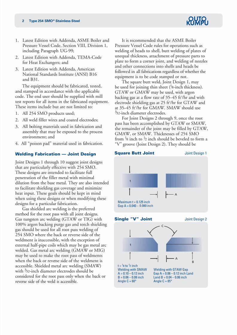
The square butt weld, Joint Design 1, may be used for joining thin sheet (1 ⁄ 8-inch thickness).GTAW or GMAW may be used, with argonbacking gas at a flow rate of 35–45 ft3/hr and withelectrode shielding gas at 25 ft3/hr for GTAW andat 35–45 ft3/hr for GMAW. SMAW should use3 ⁄ 32-inch diameter electrodes.
For Joint Designs 2 through 9, once the rootpass has been accomplished by GTAW or SMAW,the remainder of the joint may be filled by GTAW,GMAW, or SMAW. Thicknesses of 254 SMOfrom 1 ⁄ 8 inch to 1 ⁄ 2 inch should be beveled to form a “V” groove (Joint Design 2). They should be
t = 1 ⁄ 8 to 1 ⁄ 2 inchWelding with SMAW Welding with GTAW GapA = 0.10 – 0.12 inch Gap A = 0.06 – 0.12 inch LandB = 0.06 – 0.08 inch Land B = 0.04 – 0.06 inchAngle C = 60° Angle C = 85°
Single “V” Joint Joint Design 2
t
A
C
B
Maximum t = 0.125 inchGap A = 0.040 – 0.080 inch
Square Butt Joint Joint Design 1
t
A
7/30/2019 Welding of Duplex Stainless Steel.pdf
http://slidepdf.com/reader/full/welding-of-duplex-stainless-steelpdf 3/12
3Type 254 SMO® Stainless Steel
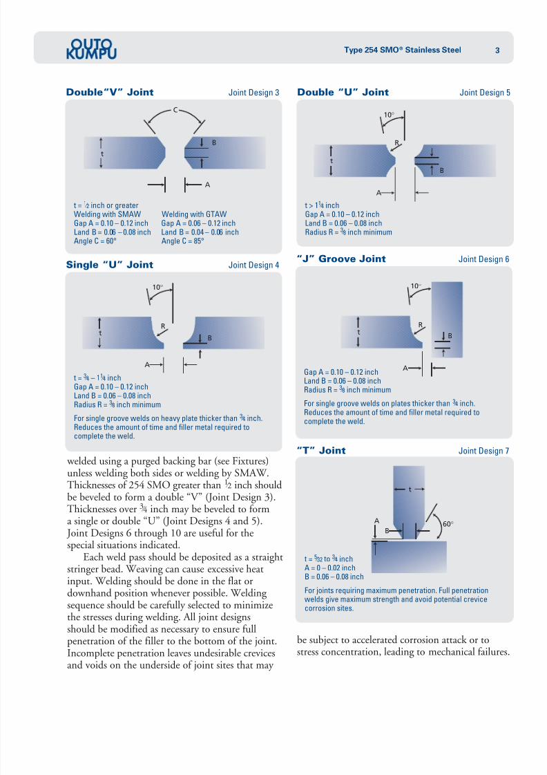
welded using a purged backing bar (see Fixtures)unless welding both sides or welding by SMAW.Thicknesses of 254 SMO greater than 1 ⁄ 2 inch shouldbe beveled to form a double “V” (Joint Design 3).Thicknesses over 3 ⁄ 4 inch may be beveled to forma single or double “U” (Joint Designs 4 and 5). Joint Designs 6 through 10 are useful for the
special situations indicated.Each weld pass should be deposited as a straight
stringer bead. Weaving can cause excessive heatinput. Welding should be done in the flat ordownhand position whenever possible. Welding sequence should be carefully selected to minimizethe stresses during welding. All joint designsshould be modified as necessary to ensure fullpenetration of the filler to the bottom of the joint.Incomplete penetration leaves undesirable crevicesand voids on the underside of joint sites that may
be subject to accelerated corrosion attack or tostress concentration, leading to mechanical failures.
t = 1 ⁄ 2 inch or greaterWelding with SMAW Welding with GTAWGap A = 0.10 – 0.12 inch Gap A = 0.06 – 0.12 inchLand B = 0.06 – 0.08 inch Land B = 0.04 – 0.06 inchAngle C = 60° Angle C = 85°
Double“V” Joint Joint Design 3
t
A
C
B
Gap A = 0.10 – 0.12 inchLand B = 0.06 – 0.08 inchRadius R = 3 ⁄ 8 inch minimum
For single groove welds on plates thicker than
3 ⁄ 4
inch.Reduces the amount of time and filler metal required tocomplete the weld.
“J” Groove Joint Joint Design 6
t
A
10o
B
R
t = 3 ⁄ 4 – 11 ⁄ 4 inchGap A = 0.10 – 0.12 inchLand B = 0.06 – 0.08 inch
Radius R =3
⁄ 8 inch minimumFor single groove welds on heavy plate thicker than 3 ⁄ 4 inch.Reduces the amount of time and filler metal required tocomplete the weld.
Single “U” Joint Joint Design 4
t
A
10o
B
R
“T” Joint Joint Design 7
t > 11 ⁄ 4 inchGap A = 0.10 – 0.12 inchLand B = 0.06 – 0.08 inchRadius R = 3 ⁄ 8 inch minimum
Double “U” Joint Joint Design 5
t
A
10o
B
R
t
60oB
A
t = 5 ⁄ 32 to 3 ⁄ 4 inchA = 0 – 0.02 inchB = 0.06 – 0.08 inch
For joints requiring maximum penetration. Full penetrationwelds give maximum strength and avoid potential crevicecorrosion sites.

7/30/2019 Welding of Duplex Stainless Steel.pdf
http://slidepdf.com/reader/full/welding-of-duplex-stainless-steelpdf 4/12
4 Type 254 SMO® Stainless Steel
Welding Fabrication —
Surface and Edge Preparation
Cleanliness is a very important factor in welding
254 SMO because introduction of impurities cangreatly reduce corrosion resistance. Shop dirt, oil,grease, crayon marking, cutting fluids, sulfurcompounds, marking inks, etc. must be removedfrom the welding surface and from a band at leasttwo inches wide on each side of the weld. Vapordegreasing or scrubbing with a suitable solvent areappropriate methods. Paint or other adherentmaterials may require use of alkaline cleaners orproprietary compounds. If the alkaline cleanerscontain either sodium sesquisilicate or sodium
carbonate, the cleaner should be removed by scrubbing with hot water.Beveling is best accomplished by machine —
usually a plate planer or other machine tool. Handgrinding, carefully performed, can be satisfactory.The land must be a true land and not a dull knifeedge. The edges of the sheet or plate should besquared, aligned, and tack welded prior to welding.The gap, as shown in the recommended Joint Designs,is essential to achieve welds of maximum corrosionresistance. Excessive dilution from the base metal isto be avoided. Square butt joints cannot be used for254 SMO over about 0.125 inch in thickness.
Welding Fabrication —
Preheating and Postheating
Preheating of 254 SMO is not recommended, exceptto the extent that cold material may be heated toroom temperature (>50°F) to prevent condensationof moisture in the weld area. If oxyacetylenepreheating is used for this purpose, the heat shouldbe applied evenly on the base metal rather than on
the prepared edge to avoid carbon pickup. Hot spotsmust be avoided.Postweld heat treating is unnecessary and
probably harmful. The only exception relates toan autogenous weld. It is recommended that allautogenous welds be avoided. However, in theevent that an autogenous weld occurs, it is necessary to give it a full anneal and quench to restorecorrosion resistance. This treatment requiresuniform heating to 2100°F minimum and very rapid cooling, ideally water quenching.
a = 0.7 x t to 1.0 x t
Conventional fillet weld. Fillet size should equal the thicknessof the thinner member. This joint design is not suited to with-stand mechanical fatigue loading. The built-in crevice in thisjoint must be completely sealed to prevent corrosion.
“T” Joint Joint Design 8
a
For Openings such as Manways,Viewports and Nozzles Joint Design 9
B
A
Shell Plate
45o
A = 0 – 0.02 inchB = 0.06 – 0.08 inch
Internal bevel allows for full penetration weld and eliminates the crevice which is a potential corrosion site.
For Installing Half Pipe Coilto Vessel, Sidewalls andTank Bottoms Joint Design 10
45o
B
A
Gap A = 0.10 – 0.12 inchGap B = 0.06 – 0.08 inch

7/30/2019 Welding of Duplex Stainless Steel.pdf
http://slidepdf.com/reader/full/welding-of-duplex-stainless-steelpdf 5/12
5Type 254 SMO® Stainless Steel
Welding Fabrication —
Gas Tungsten Arc Welding
Equipment
Gas Tungsten Arc Welding (GTAW), commonly called TIG, may be performed manually or by machine. A constant-current power supply shouldbe used, preferably equipped with a high frequency circuit for starting the arc and a stepless controlcurrent decay unit incorporated in the powersupply unit. GTAW should be done using direct-current straight polarity (DCSP), electrode negative.Use of direct-current reserve polarity (DCRP) will produce rapid electrode deterioration.
Electrode Selection and Use
The non-consumable electrode should comply with AWS Specification A5.12, Classification EW Th-2(2% thoriated tungsten electrode). The consumableelectrode (weld filler metal) should comply with AWS Specification A5.14 and ASME SpecificationSA 5.14. The AWS electrode classification isERNiCrMo-3. Alloy 625 or Avesta Welding Products P12 is appropriate. Other filler metals with sufficient chromium and molybdenumcontent to ensureadequate corrosion resistance,such as Avesta Welding Products P16, Alloy C-276,or C-22, may also be considered.
For GTAW, good arc control is obtained by grinding the tungsten electrode to a point. Vertex angles of 30 to 60 degrees with a small flat at thepoint are generally used. For automatic GTAW,the vertex angle has an influence on penetrationcharacteristics. A few simple tests to determinecorrect electrode configuration should be madebefore actual fabrication.
When welding a dissimilar metal such as another
austenitic stainless steel, a low alloy steel, or carbonsteel to 254 SMO, Alloy 625 filler may be used.However, better and more economical results canbe achieved using a stainless steel electrode such asE309LMo or other low-carbon electrode withalloy content intermediate to the dissimilar metals. When welding 254 SMO to a dissimilar metal, the welder should consider the differences in thermalexpansion and conductivity to minimize thepossibilities of weld cracking and distortion.
Weld Pool Protection
The weld pool in GTA welding should be protectedfrom atmospheric oxidation by inert gas flowing
through the welding torch. The turbulence of the inert gas, and the resulting entrainment of atmosphere, should be minimized by use of a gasdiffuser screen (gas lens) on the torch.
Operating procedures should be adjusted toensure adequate inert gas shielding. Gas flow shouldprecede arc initiation by several seconds and shouldbe held over the weld pool for at least five secondsafter the arc is extinguished. If flow is too low, the weld pool will not be adequately protected. If flow is too high, gas turbulence may aspirate air into the
weld region. Argon backing gas is required on theback side of the joint for all root passes, regardlessof joint design. The argon should be welding-grade100% argon, having a purity of 99.9% argon and a dew point of -77°F.
Approximate flow rates are 25 cubic feet perhour for the electrode and 35 to 45 cubic feet perhour for the backing purge. The enclosed volumeshould be purged a minimum of seven times before welding begins. Argon should be fed in at thebottom and out at the top because of its weightrelative to air.
Additions of oxygen and carbon dioxide shouldbe avoided for metallurgical reasons. A smalladdition of dry nitrogen may be considered. An addition of helium may also be useful undersome circumstances.
There should be regular inspections of O-ringsfor watercooled torches and of gas hoses to ensurethat only the pure, dry shielding gas is delivered tothe part.
GTAW Deposit Techniques
The joint should be prepared in one of thegeometries shown in Joint Designs 1 through 10 with attention given to surface preparation, edgepreparation, alignment, root spacing, and installationof a backing bar to ensure full argon backing gascoverage while making tack welds and the root pass.
Ignition of the arc should always take place within the joint itself. Any strike scars alongsidethe joint should be removed by fine grinding.
7/30/2019 Welding of Duplex Stainless Steel.pdf
http://slidepdf.com/reader/full/welding-of-duplex-stainless-steelpdf 6/12
6 Type 254 SMO® Stainless Steel
Tack welds of appropriate length andspacing should be made with full argon shielding.The root pass should be made using Alloy 625 or Avesta Welding Products P12 filler and theappropriate shielding gas flow. The arc energy input should not exceed 38 kJ/inch. There shouldbe no tack weld at the starting point of the actualroot pass weld. To avoid cracking in the root passrelated to tack welds, the welder should interruptthe root pass before a tack weld. The welder shouldeither grind away the tack completely with a slitting wheel grinder, or make the tack shorter by grinding the start and finish of the tack prior to recommenc-ing the root pass. The width of the root gap shouldbe maintained against shrinkage.
The start and finish of the root pass weldshould be ground off prior to the start of any fillerpasses. Straight stringer beads should be used. Themetal should be allowed to cool to less than 212°Fbetween passes. The joint may be filled using additional passes with 1 ⁄ 16-, 3 ⁄ 32-, or 1 ⁄ 8-inch diameterfiller metal with 100% argon shielding gas. GTA welding generally gives the best results when donein the flat position but vertical welds can be madesuccessfully. The torch should be as close toperpendicular to the workpiece as possible.
Excessive deviation from perpendicular may cause air to be drawn into the shielding gas.The filler wire should be kept clean at all times.Filler wire should be stored in a covered container when not in use.
After welding, any heat tint should be removedby fine grinding, using as fine an abrasive aspossible while still removing heat tint in a reasonabletime. Abrasive blasting with 75-100 micronsoda-lime glass beads is also acceptable. The use of carbon steel brushes is prohibited. Even stainless
steel brushes using common grade stainless forthe wire are not acceptable unless there is to besubsequent chemical cleaning of the weld.These precautions are designed to prevent ironcontamination of the surface that might initiateattack in aggressive chloride environments. Alternatively, heat tint may be removed by use of Avesta Welding Products RedOne 140 paste or240 spray gel or acid treatment followed by thorough rinsing of the acid from the metal.
Welding Fabrication —
Gas Metal Arc Welding
Equipment
Gas Metal Arc Welding (GMAW), commonly called MIG, is performed using a constant voltagepower supply with variable slope and variableinductance control or with pulsed arc currentcapability. Three arc transfer modes are available:
Short Circuiting Transfer
The power source must have separate slope andsecondary inductance controls. It is used for materialup to 0.125 inch thick. Short circuiting transferoccurs with low heat input and is particularly useful when joining thin sections that could bedistorted by excessive heat. It is also useful forout-of-position welding.
Pulsed Arc Transfer
Two power sources are required, one for each of the two ranges. Switching sources produces thepulsed output. The current has its peak in the spray transfer range and its minimum in the globularrange. This method provides the benefits of spray
arc but limits heat input, making the method usefulin all positions.
Spray Transfer
Spray transfer is accompanied by high heat inputbut it gives a stable arc and high deposition rates.It is generally limited to flat-position welding.Because of total heat input considerations, shortcircuiting transfer and pulsed arc transfer arepreferred methods of GMAW for 254 SMO.GMAW should be done with direct-current reverse
polarity (DCRP), electrode positive.
Electrode Selection and Use
GMAW uses a consumable electrode in the form of a continuous solid wire usually supplied on a layer-wound spool and fed through the GMA torchby an automatic wire feed system. This electrode(weld filler) shall comply with AWS Specification A5.14 and the ASME Specification SA5.14.The AWS electrode classification is ERNiCrMo-3.

7/30/2019 Welding of Duplex Stainless Steel.pdf
http://slidepdf.com/reader/full/welding-of-duplex-stainless-steelpdf 7/12
7Type 254 SMO® Stainless Steel
Alloy 625 or Avesta Welding Products P12 areacceptable fillers. As noted for GTAW, Avesta Welding Products P16, Alloy C-276, or similar fillersmay also be considered. Other fillers may beconsidered when joining dissimilar metals. Thecommon wire sizes for GMAW are smaller thanthose for GTAW, the most common being 0.035,0.045, and 0.062 inch.
The speed of electrode feed is a direct functionof welding current and wire diameter.
Typical welding parameters for spray arc transfer,using 99.95% argon shielding gas, 35 to 55 ft3/hr, areshown in Table 1:
Typical welding parameters for short circuiting arc transfer, using 99.95% argon shielding gas,25 to 45 ft3/hr, are shown in Table 2:
If helium is added to flatten the bead, theshielding gas flow rate should be at the upper endof the range.
Weld Pool Protection
The weld pool in GMA welding should be protectedfrom atmospheric oxidation by inert gas flowing through the GMA torch. The shielding gas is typically 100% welding-grade argon, but up to 25% heliummay be used for pulsed arc or short circuiting arc welding. Another gas that has satisfactory results isargon — 30-35% helium — 0.5-1.5% carbondioxide. Appropriate flow rates are 45, 50, and55 ft3/hr for 0.035, 0.045, and 0.062 inch diameter wire, respectively. There should be regular inspectionsof O-rings in water-cooled torches and of gas hoses.
Welding in the presence of air drafts, regardless of weld position, should be avoided.
Deposit Techniques
The joint should be prepared in one of the geometriesshown in Joint Designs 1 through 10, with attentiongiven to surface preparation, edge preparation,alignment, root gap, and installation of a backing bar to ensure full argon backing gas coverage whilemaking tack welds and the root pass.
Ignition of the arc should always take place within the joint itself. Any strike scars alongside of the joint should be removed by fine grinding.
Tack welds of appropriate length and
spacing should be made with full argon shielding.The root pass should be made using Alloy 625, Avesta Welding Products P12, or Avesta Welding Products P16 filler with the appropriate shielding gas flow. The arc energy input should not exceed38 kJ/inch. There should be no tack weld at thestarting point of the actual root pass weld. To avoidcracking in the root pass related to tack welds, the welder should interrupt the root pass before a tack weld. The welder should either grind away the tack completely with a slitting wheel grinder, or makethe tack shorter by grinding the start and finish of the tack prior to recommencing the root pass. The width of the root gap should be maintained againstshrinkage.
The start and finish of the root pass weldshould be ground prior to the start of any fillerpasses. Straight stringer beads should be used. Themetal should be allowed to cool to less than 212°Fbetween passes. The joint may be filled using additional passes with 0.035- or 0.045-inchdiameter Alloy 625, Avesta Welding Products P12,or Avesta Welding Products P16 filler metal with
100% argon backing gas and either 100% argon or75% argon–25% helium shielding gas. GMA welding generally gives best results when done inthe flat position but vertical welds can be madesuccessfully. The torch should be as close toperpendicular to the workpiece as possible.Excessive deviation from perpendicular may causeair to be drawn into the shielding gas. The filler wire and guide tube should be kept clean at alltimes. Filler wire should be stored in a coveredcontainer when not in use.
WireDiameter (inch) Amperes Volts
0.035 90-120 19-21
0.045 110-140 20-22
Table 2
WireDiameter (inch) Amperes Volts
0.035 170-190 28
0.035 220-280 30
0.062 280-330 31
Table 1
7/30/2019 Welding of Duplex Stainless Steel.pdf
http://slidepdf.com/reader/full/welding-of-duplex-stainless-steelpdf 8/12
8 Type 254 SMO® Stainless Steel
After welding, any heat tint should be removedby fine grinding, using as fine an abrasive as possible while still removing heat tint in a reasonable time. Abrasive blasting with 75 to 100 micron soda-limeglass beads is also acceptable. The use of carbonsteel brushes is prohibited. Even stainless steelbrushes using common grade stainless for the wireare not acceptable, unless there is to be subsequentchemical cleaning of the weld. These precautionsare designed to prevent iron contamination of thesurface that might initiate pitting in aggressivechloride environments. Alternatively, heat tintmay be removed by use of Avesta Welding ProductsRedOne 140 paste or 240 spray gel or acidtreatment, followed by thorough rinsing of the acid
from the metals.
Welding Fabrication —
Shielded Metal Arc Welding
Equipment
Shielded Metal Arc Welding (SMAW), commonly called stick or covered electrode welding, isperformed using a constant- current power supply.SMA welding is done using direct-current reversepolarity (DCRP), electrode positive.
Electrode Selection and Use
SMA welding uses a consumable electrode in theform of a core wire covered by a coating. The coating provides arc stability, shields the molten metalduring arc transfer, and protects the weld during solidification. In some cases, the coating may provide a portion of the alloy content of the weldfiller. The consumable electrode should comply with AWS Specification A5.11. The AWS electrodeclassification is ENiCrMo-3 for the 112 electrode.
(Avesta Welding Products P12R electrode has AWScoverage as ENiCrMo-12). As noted for GTAW, Alloy C-276, Avesta Welding Products P16, orsimilar fillers may also be considered. These electrodescan be used in all positions.
Electrodes are furnished in airtight containersbecause moisture in the electrode coating willproduce weld porosity and poor bend ductility.Once the container is opened, the electrodes shouldbe stored in a commercial electrode oven heated toat least 200°F to maintain dry coating.
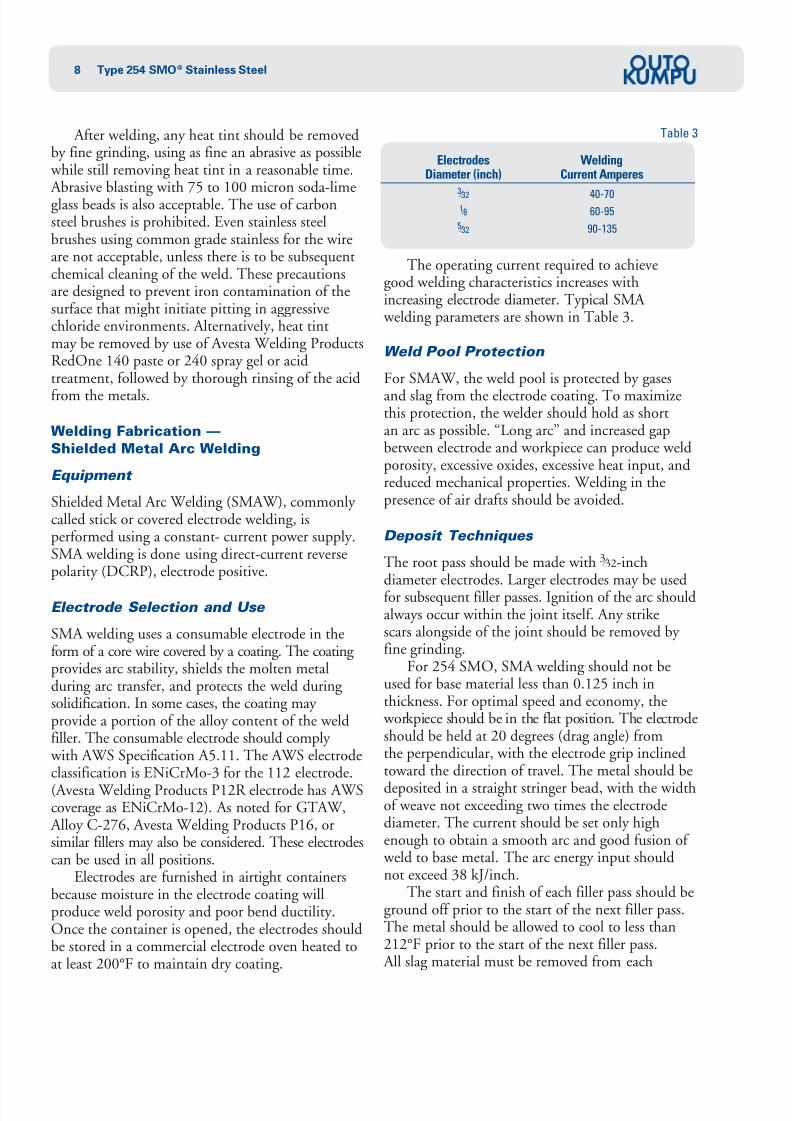
The operating current required to achievegood welding characteristics increases withincreasing electrode diameter. Typical SMA welding parameters are shown in Table 3.
Weld Pool Protection
For SMAW, the weld pool is protected by gases
and slag from the electrode coating. To maximizethis protection, the welder should hold as shortan arc as possible. “Long arc” and increased gapbetween electrode and workpiece can produce weldporosity, excessive oxides, excessive heat input, andreduced mechanical properties. Welding in thepresence of air drafts should be avoided.
Deposit Techniques
The root pass should be made with 3 ⁄ 32-inchdiameter electrodes. Larger electrodes may be usedfor subsequent filler passes. Ignition of the arc shouldalways occur within the joint itself. Any strikescars alongside of the joint should be removed by fine grinding.
For 254 SMO, SMA welding should not beused for base material less than 0.125 inch inthickness. For optimal speed and economy, the workpiece should be in the flat position. The electrodeshould be held at 20 degrees (drag angle) fromthe perpendicular, with the electrode grip inclinedtoward the direction of travel. The metal should be
deposited in a straight stringer bead, with the widthof weave not exceeding two times the electrodediameter. The current should be set only highenough to obtain a smooth arc and good fusion of weld to base metal. The arc energy input shouldnot exceed 38 kJ/inch.
The start and finish of each filler pass should beground off prior to the start of the next filler pass.The metal should be allowed to cool to less than212°F prior to the start of the next filler pass. All slag material must be removed from each
Electrodes WeldingDiameter (inch) Current Amperes
3 ⁄ 32 40-70
1 ⁄ 8 60-95
5 ⁄ 32 90-135
Table 3
7/30/2019 Welding of Duplex Stainless Steel.pdf
http://slidepdf.com/reader/full/welding-of-duplex-stainless-steelpdf 9/12
9Type 254 SMO® Stainless Steel
filler pass. After welding, any heat tint should beremoved by fine grinding, using as fine an abrasiveas possible, while still removing heat tint in a reasonable time. Abrasive blasting with 75-100micron soda-lime glass beads is also acceptable.The use of carbon steel brushes is prohibited. Evenstainless steel brushes using common-grade stainlessfor the wire are not acceptable, unless there is to besubsequent chemical cleaning of the weld. Theseprecautions are designed to prevent ironcontamination of the surface that might initiatepitting in aggressive chloride environments. Alternatively, heat tint may be removed by use of Avesta Welding Products RedOne 140 paste or240 spray gel or acid treatment, followed by
thorough rinsing of the acid from the metal. When SMA welding is used for the root pass,
the root side should subsequently be groundsmooth. All weld spatter, slag, and heat tint shouldbe removed.
SMA welds may be subject to starting porosity because the electrode requires a few seconds togenerate sufficient shielding to protect the arc.Voids at the end of a weld are usually attributed toshrinkage caused by the sudden extinction of the arc.This problem is overcome by a slight backstepping,
a momentary reversal in travel just before the arcis broken. To obtain the highest quality welddeposits, the best practice is to grind all starting and topping points.
Welding Fabrication —
Submerged Arc Welding
Earlier publications indicated that submerged arc welding (SAW) should not be applied to 254 SMOsteel because of risk of carbon or silicon pick-up fromthe flux. There was also the risk of microfissuring
associated with the relatively high heat input of SAW. These concerns have been addressed. SAW, with appropriate controls, is now commonly applied to 254 SMO. For example, SAW isregularly used in production of heavy-wall pipe.
Selection of flux is important. Avesta Welding Products 805 flux was designed for highly alloyedstainless steels. This chromium-enriched flux provides good weldability, good ease of removal,and superior final appearance.
Control of heat input to prevent microfissuring
is critical. Precautions include adherence to heatinput limitations, use of small-diameter wire, use of U-joints where possible, and uniformity of the jointgeometry and alignment. Limitation of interpasstemperature is essential.
Welding Fabrication —
Prohibited Welding Processes
Oxyacetylene welding cannot be used for 254 SMObecause carbon pick-up from the flame willsubstantially lower corrosion resistance.
Autogenous welding (no filler metal), regard-less of welding process, should not be used becausemicrosegregation within the weld metal during
solidification will greatly reduce corrosion resistance.Corrosion resistance of an autogenous weld can berecovered by a full anneal and quench, but suchpractice is seldom applicable to practical engineeringconstructions, whether new or repair welding.In the application of the recommended welding practices, care must be taken in the geometry andperformance of the weld that there is no opportunity for autogenous solidification.
Welding Fabrication —
Interpass Temperatures and Cooling
Interpass temperature of 254 SMO should notexceed 212°F. Auxiliary cooling methods may be used between passes to speed the overall welding operation, provided that they do notintroduce contamination of the joint. Examplesof contamination may include oil from a shopair line, grease or dirt from water-soaked rags, oreven mineral deposits from hard water.
When attaching hardware to the exterior of a thin-walled vessel, the fabricator should provide
auxiliary cooling to the inside of the vessel wall tominimize heat-affected zone effects. The surfacetemperature of the internal vessel surface of 254 SMO should not exceed about 1100°F.
Welding Fabrication —
Controlling Distortion
Controlling distortion of 254 SMO is notsignificantly different from controlling distortionof the common austenitic grades. It may actually beeasier because of the low heat input practices used

7/30/2019 Welding of Duplex Stainless Steel.pdf
http://slidepdf.com/reader/full/welding-of-duplex-stainless-steelpdf 10/12
10 Type 254 SMO® Stainless Steel
for 254 SMO. Good practice includes properfixturing, cross supports, bracing, staggered beadplacement and weld sequence, etc. The edges of the plate or sheet should be squared, aligned, andtacked prior to welding.
Welding Fabrication — Fixtures A square-corner, grooved backing bar is recommendedfor providing inert gas coverage during root passes. A typical chill bar cross-section is shown in Figure1, featuring a square-corner groove and drilledholes for gas purging. Groove depth is a function of the gas flow required and the length of the bar. Thebacking bar also serves as a chill to the base metaland a support to prevent excessive penetration of the weld bead.
It is essential that there not be abrasive contact
of 254 SMO with copper or brass in any area thatis to be subsequently welded. Penetration of copperor zinc into grain boundaries can give rise tocrack formation.
Descaling, Pickling, and
Surface Condition
Oxide, tarnish, heat tint, or other surfacecontamination can be removed by mechanical orchemical methods, ideally a combination of thetwo. Mechanical methods include fine grinding
and polishing and abrasive blasting with 75-100micron soda-lime glass beads. Subsequent chemicalcleaning is not required after either of these methods,but subsequent chemical cleaning is good practicebecause it guards against contamination from themechanical cleaning medium.
Wire brush cleaning is generally insufficientunless it is followed by chemical cleaning. Steel wirebrushes, and even stainless steel wire brushes, canleave behind a residue of iron contamination thatcould lead to initiation of pitting in aggressivechloride environments.
Prior to any chemical cleaning, the user shouldconsult ASTM A 380 regarding correct proceduresand precautions. Chemical cleaning is readily
accomplished using a pickling solution of 20%nitric acid–5% hydrofluoric acid in water,commercially available solutions or pastes of similaringredients, or Avesta Welding Products RedOne140 paste or 240 spray gel.
Proper precautions must be taken when handling pickling solutions and pastes. Positive ventilation isrequired to remove fumes. Protective clothing, faceshields, and rubber gloves must be worn. Properenvironmental procedures are required for thedisposal of wash liquors from pickling operations.
Workmanship, Inspection, and
Quality Control
The ease of fabrication of 254 SMO is intermediateto that of austenitic stainless steels, such as Type 316Lor 317L, and that of nickel-base alloys, such as Alloy G or 625. Consequently, fabrication should beperformed by skilled workers, ideally ASME Code–qualified in these other alloys. With such experience, workers require only brief familiarization procedures.
Because 254 SMO is frequently selected for
service in components critical to process operations,the welds should be rigorously inspected. Straightstringer beads with a distinct crown (convex surface)are essential to best quality. No pits, porosity,cracks, pinholes, slag inclusions, undercutting,overheating, or other weld defects should beaccepted in fabricated equipment. Completepenetration is required on the entire length of weld. Arc strikes and breaks outside of the weld zonemust be removed by fine grinding. Care must betaken that all slag is removed between passes. All
Square-corner groove employed with backing gas (groovedepth depends on gas flow required and length of bar).
Groove Design for Backing Bars Figure 1
Section B-B
3 inch approx.
BB
3 / 16 to 1 / 4
inches
1 / 16 inch
diameter3 / 16 to
3 / 8 inch
diameter
7/30/2019 Welding of Duplex Stainless Steel.pdf
http://slidepdf.com/reader/full/welding-of-duplex-stainless-steelpdf 11/12
11Type 254 SMO® Stainless Steel
weld spatter should be removed by fine grinding.In addition to mandatory non-destructive
tests required for ASME Code fabrications, it isrecommended that other test methods such asradiographic, dye-penetrant, ultrasonic, andhydrostatic be used where practical, to ensurebest weld quality. Such tests are useful both forintermediate inspections during fabrication and forfinal inspection.
All rejectable weld defects should be completely removed by grinding. The ground crater should bedye-penetrant inspected to ensure that the defect iscompletely removed. The area of the repair shouldbe thoroughly cleaned and then welded by one of the described procedures. It is not good practice
to attempt to heal cracks or wash-out defects by remelting of weld beads or by deposition of additional weld beads.
Outokumpu
Welding Consumables
Avesta Welding Products, Inc. provides coatedelectrodes, wires for GTAW, GMAW, and SAW,pickle paste, pickle spray, and welding fluxes, all of which have been formulated to produce excellentresults when welding 254 SMO. For these products,call Avesta Welding Products, Inc. at 1-800-441-7343.
Technical Support
Outokumpu assists users and fabricators in theselection, qualification, installation, operation, andmaintenance of 254 SMO stainless steel. Technicalpersonnel, supported by the research laboratory of Outokumpu, can draw on years of field experience with 254 SMO to help you make the technically and economically correct materials decision.
Outokumpu is prepared to discuss individualapplications and to provide data and experience asa basis for selection and application of 254 SMO.
Outokumpu works closely with its distributorsto ensure timely availability of 254 SMO in theforms, sizes, and quantities required by the user.For assistance with technical questions and toobtain top quality 254 SMO, contact Outokumpuat 1-800-833-8703.
Outokumpu is pleased to acknow ledge the contribution to the original manuscript for this recommended welding practice by Ralph J. Valentine,VAL-CORR Corp., Portage, Michigan.
7/30/2019 Welding of Duplex Stainless Steel.pdf
http://slidepdf.com/reader/full/welding-of-duplex-stainless-steelpdf 12/12
12 Type 254 SMO® Stainless Steel
www.outokumpu.com/stainless/na
Outokumpu 425 North Martingale Road, Suite 1600, Schaumburg, IL 60173-2218 USA
Tel. 1-800-833-8703 Fax 1-800-545-8617
254 SMO is a trademark of Outokumpu Stainless.
Outokumpu is a global leader in stainless steel. Our vision is to be the undisputed number one in stainless, with success based on operational excellence.Customers in a wide range of industries use our stainless steel and services worldwide. Being fully recyclable, maintenance-free, as well as very strong and durable material, stainless steel is one of the key building blocks for sustainable future.
What makes Outokumpu special is total customer focus – all the way, from R&D to delivery. You have the idea. We offer world-class stainless steel,
technical know-how and support. We activate your ideas.
Information given in this brochure may be subject to alterations without notice. Care has been taken to ensure that the contents of thispublication are accurate but Outokumpu and its affiliated companies do not accept responsibility for errors or for information that is found tobe misleading. Suggestions for or descriptions of the end use or application of products or methods of working are for information only andOutokumpu and its affiliated companies accept no liability in respect thereof. Before using products supplied or manufactured by the company the customer should satisfy himself of their suitability.
1 0 64EN , S ch a um b ur g , U SA.D e c em b er 2 0 0 0
8.