welding installation procedure
TRANSCRIPT
8/4/2019 Welding Installation Procedure
http://slidepdf.com/reader/full/welding-installation-procedure 1/33
installation instruction
Page: 1 (33)
Status: APPROVED
Table of contents
1. The danger of electricity ......................................................................................... 3 Example........................................................................................................................................... 4
2. Grounding of work piece ........................................................................................ 4
Avoid branch grounded current....................................................................................................... 5
Avoid series connection .................................................................................................................. 6
3. Hot welding sparks.................................................................................................. 7
Protect yourself and the environment.............................................................................................. 7
4. Noise.......................................................................................................................... 8
5. How to treat the welding equipment ................................................................... 10
Arc and gas arch welding equipment ............................................................................................ 10
Siting and cabling.......................................................................................................................... 10
Welding machines......................................................................................................................... 10
6. Welding methods................................................................................................... 10
7. Welders................................................................................................................... 11
8. Welding examples at site ......................................................................................11
9. Selection and use of welding consumables .......................................................... 15
Storage and drying of welding consumables................................................................................. 16
10. Welding requirements........................................................................................... 18
Compliance with next tables ......................................................................................................... 18
Acceptance levels for surface and internal defects and imperfect shape and defective geometry of
butt joints............................................................................................................................ 19
11. End preparation and cleaning.............................................................................. 23
11.1. Cleaning ...............................................................................................................23 11.2. Pipes.....................................................................................................................23
Doc. id: WDAAA116762 a
8/4/2019 Welding Installation Procedure
http://slidepdf.com/reader/full/welding-installation-procedure 2/33
Wärtsilä Finland Oy
Doc id: WDAAA116762 a
Page: 2 (33)
Bevelling ....................................................................................................................................... 23
Fitting 23
11.3. Elbows, reducers, caps, tees and valves with weld ends...............................23
11.4. Flanges.................................................................................................................23
Flanges for welding....................................................................................................................... 24
11.5. Joint preparations for butt welds ......................................................................26
Butt welds welded from one side .................................................................................................. 27
Butt welds welded from both sides ............................................................................................... 30
11.6. Branches ..............................................................................................................33
Edge preparation............................................................................................................................ 33 Fitting 33
12. Inspection of welds ................................................................................................ 33
Date: 25-Apr-2005
8/4/2019 Welding Installation Procedure
http://slidepdf.com/reader/full/welding-installation-procedure 3/33
Wärtsilä Finland Oy
Doc id: WDAAA116762 a
Date: 25-Apr-2005
Page: 3 (33)
Thedanger of electr icity
WARNING! Electricity can be mortal!
The intensity and effective time of the current as well as its frequency and path
contribute to the dangerousness of the electricity when leading through the human
body. Alternating current is more dangerous than direct current and the most
dangerous range is 15..100 Hz.
The current intensity depends on voltage and resistance in the circuit.
UI = R
where I= current
U=voltage
R=resistance
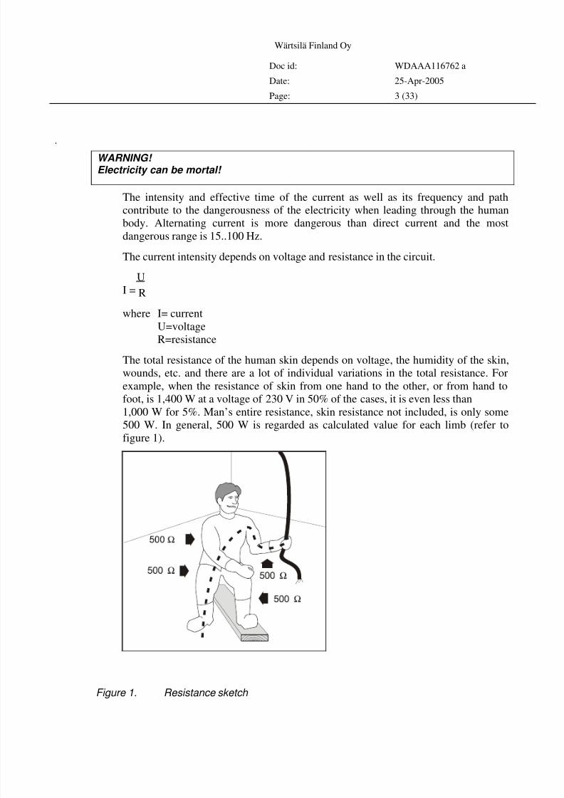
The total resistance of the human skin depends on voltage, the humidity of the skin,
wounds, etc. and there are a lot of individual variations in the total resistance. For
example, when the resistance of skin from one hand to the other, or from hand to
foot, is 1,400 W at a voltage of 230 V in 50% of the cases, it is even less than
1,000 W for 5%. Man’s entire resistance, skin resistance not included, is only some
500 W. In general, 500 W is regarded as calculated value for each limb (refer to
figure 1).
Figure 1. Resistance sketch
8/4/2019 Welding Installation Procedure
http://slidepdf.com/reader/full/welding-installation-procedure 4/33
Wärtsilä Finland Oy
Doc id: WDAAA116762 a
Date: 25-Apr-2005
Page: 4 (33)
Example
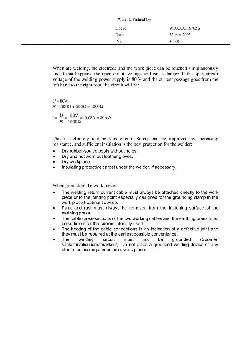
When arc welding, the electrode and the work piece can be touched simultaneously
and if that happens, the open circuit voltage will cause danger. If the open circuit
voltage of the welding power supply is 80 V and the current passage goes from the
left hand to the right foot, the circuit will be:
This is definitely a dangerous circuit. Safety can be improved by increasing
resistance, and sufficient insulation is the best protection for the welder:
• Dry rubber-souled boots without holes.
• Dry and not worn out leather gloves.
• Dry workplace.
• Insulating protective carpet under the welder, if necessary.
Gr oundingof wor kpiece
When grounding the work piece:
• The welding return current cable must always be attached directly to the workpiece or to the jointing point especially designed for the grounding clamp in thework piece treatment device.
• Paint and rust must always be removed from the fastening surface of theearthing press.
• The cable cross-sections of the two working cables and the earthing press mustbe sufficient for the current intensity used.
• The heating of the cable connections is an indication of a defective joint andthey must be repaired at the earliest possible convenience.
• The welding circuit must not be grounded (Suomensähköturvalisuusmääräykset). Do not place a grounded welding device or anyother electrical equipment on a work piece.
8/4/2019 Welding Installation Procedure
http://slidepdf.com/reader/full/welding-installation-procedure 5/33
Wärtsilä Finland Oy
Doc id: WDAAA116762 a
Date: 25-Apr-2005
Page: 5 (33)
Avoidbranchgroundedcurrent
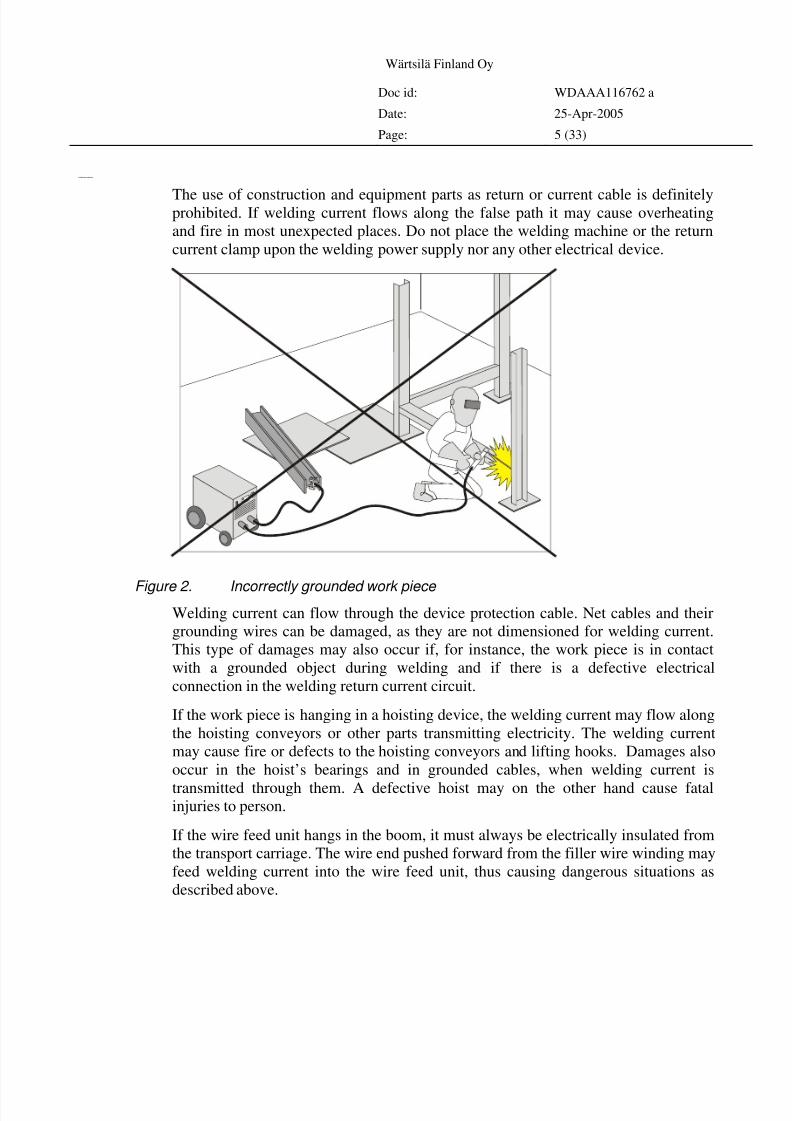
The use of construction and equipment parts as return or current cable is definitelyprohibited. If welding current flows along the false path it may cause overheating
and fire in most unexpected places. Do not place the welding machine or the return
current clamp upon the welding power supply nor any other electrical device.
Figure 2. Incorrectly grounded work piece
Welding current can flow through the device protection cable. Net cables and their
grounding wires can be damaged, as they are not dimensioned for welding current.
This type of damages may also occur if, for instance, the work piece is in contact
with a grounded object during welding and if there is a defective electrical
connection in the welding return current circuit.
If the work piece is hanging in a hoisting device, the welding current may flow along
the hoisting conveyors or other parts transmitting electricity. The welding current
may cause fire or defects to the hoisting conveyors and lifting hooks. Damages also
occur in the hoist’s bearings and in grounded cables, when welding current is
transmitted through them. A defective hoist may on the other hand cause fatalinjuries to person.
If the wire feed unit hangs in the boom, it must always be electrically insulated from
the transport carriage. The wire end pushed forward from the filler wire winding may
feed welding current into the wire feed unit, thus causing dangerous situations as
described above.
8/4/2019 Welding Installation Procedure
http://slidepdf.com/reader/full/welding-installation-procedure 6/33
Wärtsilä Finland Oy
Doc id: WDAAA116762 a
Date: 25-Apr-2005
Page: 6 (33)
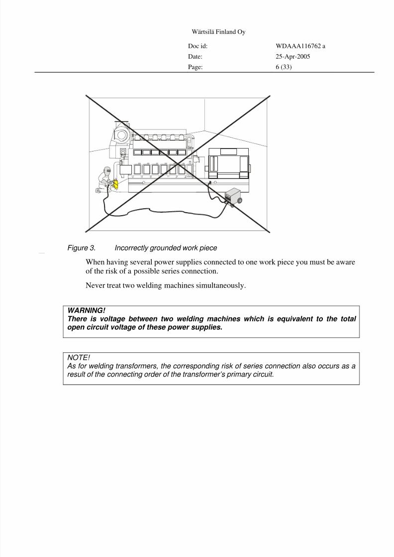
Figure 3. Incorrectly grounded work piece Avoidseriesconnection
When having several power supplies connected to one work piece you must be aware
of the risk of a possible series connection.
Never treat two welding machines simultaneously.
WARNING! There is voltage between two welding machines which is equivalent to the total open circuit voltage of these power supplies.
NOTE! As for welding transformers, the corresponding risk of series connection also occurs as a result of the connecting order of the transformer’s primary circuit.
8/4/2019 Welding Installation Procedure
http://slidepdf.com/reader/full/welding-installation-procedure 7/33
Wärtsilä Finland Oy
Doc id: WDAAA116762 a
Date: 25-Apr-2005
Page: 7 (33)
Hotweldingspar ks
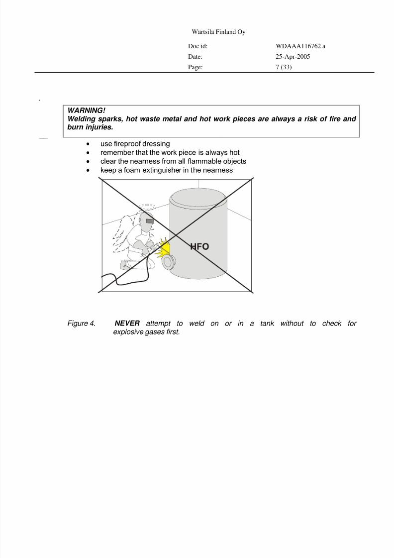
WARNING! Welding sparks, hot waste metal and hot work pieces are always a risk of fire and burn injuries.
Protectyourselfandtheenvironment
• use fireproof dressing
• remember that the work piece is always hot
• clear the nearness from all flammable objects
• keep a foam extinguisher in the nearness
Figure 4. NEVER attempt to weld on or in a tank without to check for explosive gases first.
8/4/2019 Welding Installation Procedure
http://slidepdf.com/reader/full/welding-installation-procedure 8/33
Wärtsilä Finland Oy
Doc id: WDAAA116762 a
Date: 25-Apr-2005
Page: 8 (33)
Noise
Noise is produced from the welding arc during pulse MIG welding and at larger
current intensity when MIG welding.
The major sources of noise are the welding peripheral functions: slag-outs,
straightening and assembling hammering, disk cutting & bobbing and carbon arc
forming. Always use hearing protectors in such situations.
The A-noise level caused by the MMA and TIG welding is generally lower than 85
dB. MAG/MIG causes an A-noise level which exceeds 85 dB. The total A equivalent
level of the welding place often exceeds the limit of 85 dBA, therefore hearing
protectors are recommended.
The noise level caused by plasma cutting is generally 80-120 dB, therefore the use of
hearing protectors is always necessary.
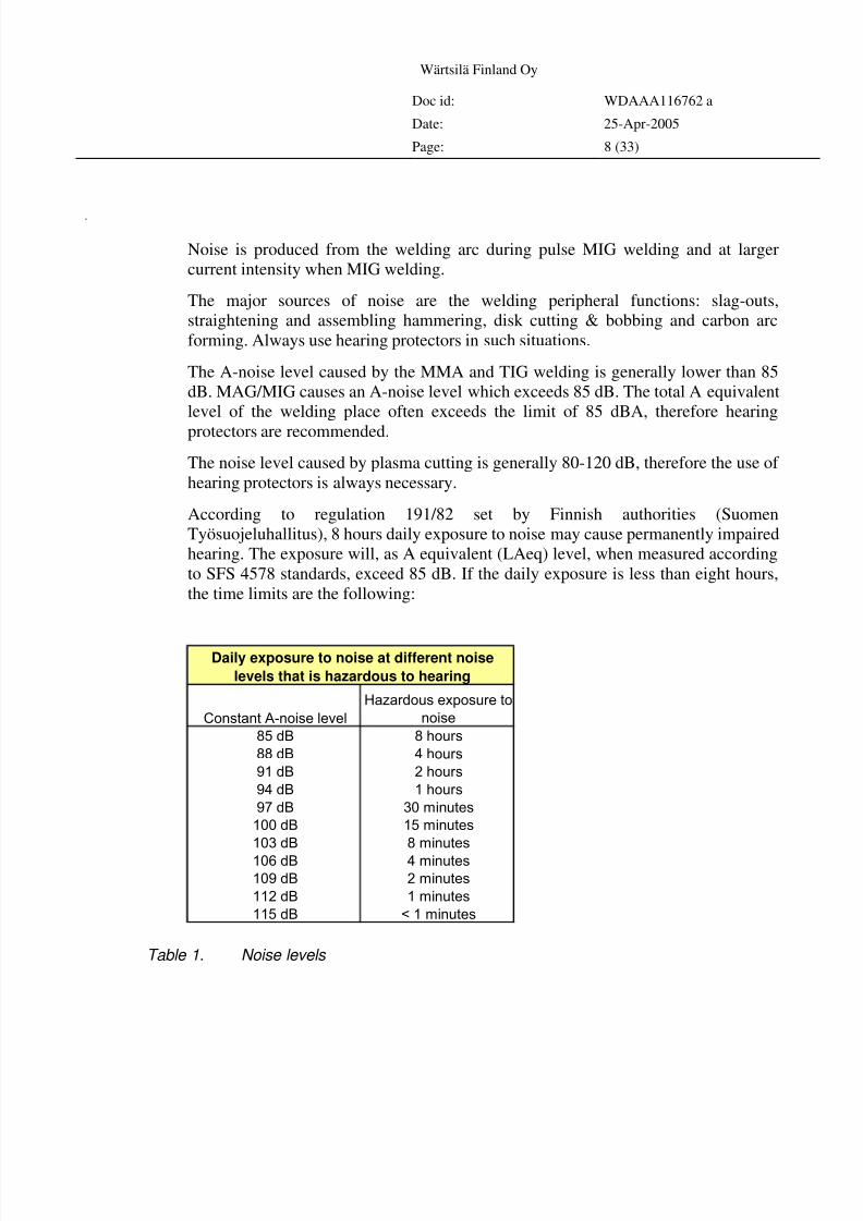
According to regulation 191/82 set by Finnish authorities (Suomen
Työsuojeluhallitus), 8 hours daily exposure to noise may cause permanently impaired
hearing. The exposure will, as A equivalent (LAeq) level, when measured according
to SFS 4578 standards, exceed 85 dB. If the daily exposure is less than eight hours,
the time limits are the following:
Constant A-noise level
Hazardous exposure to
noise
85 dB 8 hours
88 dB 4 hours
91 dB 2 hours
94 dB 1 hours
97 dB 30 minutes
100 dB 15 minutes
103 dB 8 minutes
106 dB 4 minutes
109 dB 2 minutes
112 dB 1 minutes
115 dB < 1 minutes
Daily exposure to noise at different noise
levels that is hazardous to hearing
Table 1. Noise levels
8/4/2019 Welding Installation Procedure
http://slidepdf.com/reader/full/welding-installation-procedure 9/33
Wärtsilä Finland Oy
Doc id: WDAAA116762 a
Date: 25-Apr-2005
Page: 9 (33)
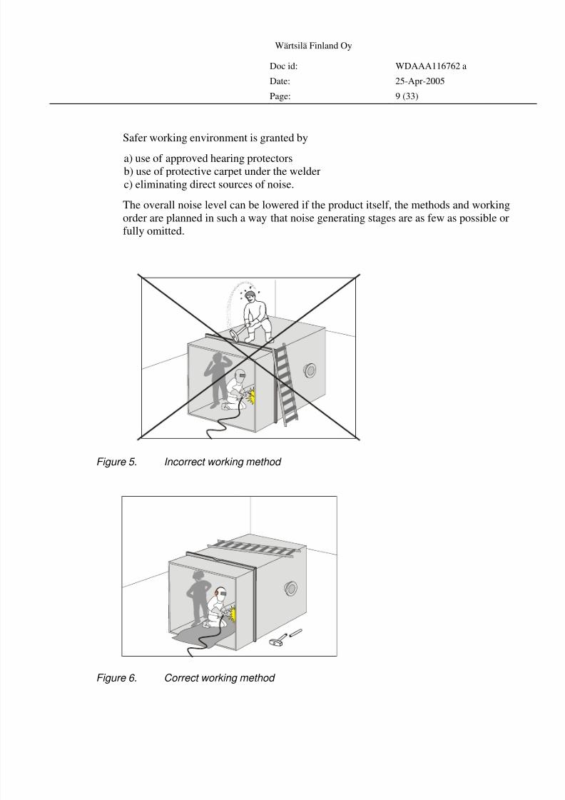
Safer working environment is granted by
a) use of approved hearing protectors
b) use of protective carpet under the welder
c) eliminating direct sources of noise.
The overall noise level can be lowered if the product itself, the methods and working
order are planned in such a way that noise generating stages are as few as possible or
fully omitted.
Figure 5. Incorrect working method
Figure 6. Correct working method
8/4/2019 Welding Installation Procedure
http://slidepdf.com/reader/full/welding-installation-procedure 10/33
Wärtsilä Finland Oy
Doc id: WDAAA116762 a
Date: 25-Apr-2005
Page: 10 (33)
Howtotr eattheweldingequipment
Arcandgasarchweldingequipment
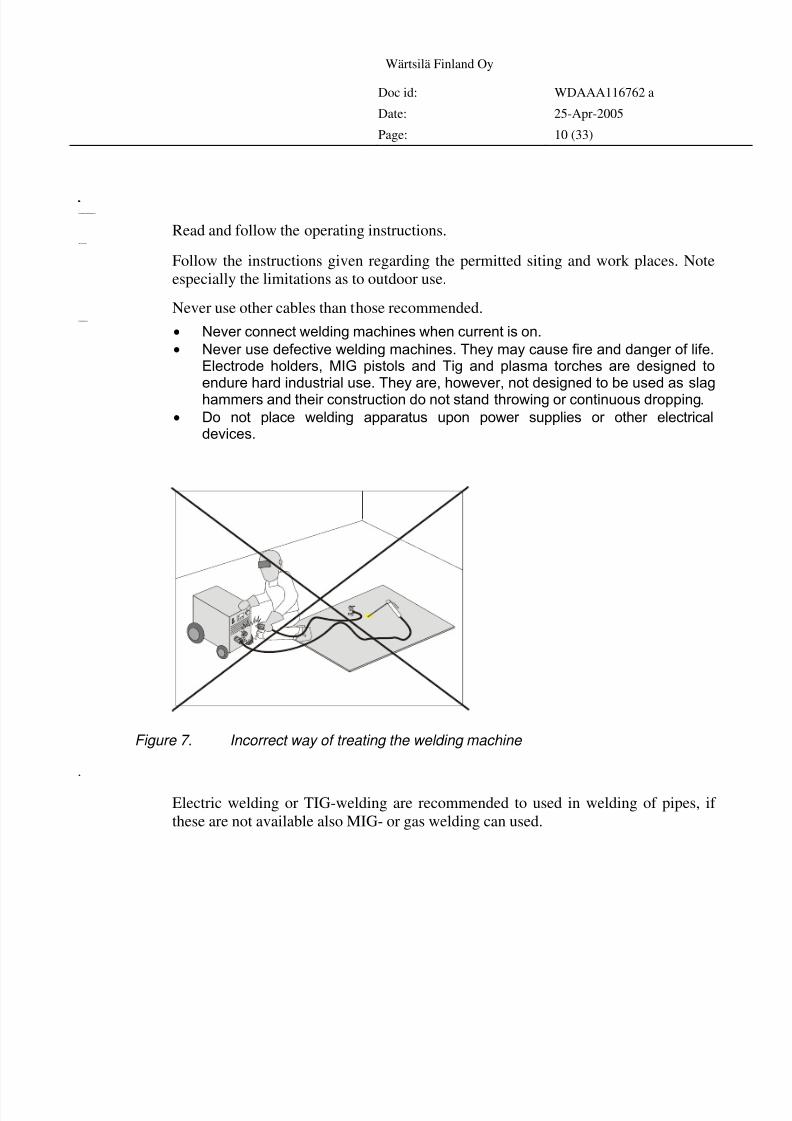
Read and follow the operating instructions.Sitingandcabling
Follow the instructions given regarding the permitted siting and work places. Note
especially the limitations as to outdoor use.
Never use other cables than those recommended.Weldingmachines
• Never connect welding machines when current is on.
• Never use defective welding machines. They may cause fire and danger of life.Electrode holders, MIG pistols and Tig and plasma torches are designed toendure hard industrial use. They are, however, not designed to be used as slaghammers and their construction do not stand throwing or continuous dropping.
• Do not place welding apparatus upon power supplies or other electricaldevices.
Figure 7. Incorrect way of treating the welding machine
Weldingmethods
Electric welding or TIG-welding are recommended to used in welding of pipes, if
these are not available also MIG- or gas welding can used.
8/4/2019 Welding Installation Procedure
http://slidepdf.com/reader/full/welding-installation-procedure 11/33
Wärtsilä Finland Oy
Doc id: WDAAA116762 a
Date: 25-Apr-2005
Page: 11 (33)
Welder s
All welders that will be doing any kind of welding work at site must be qualified and
have valid welding certificates.
Likewise, welders employed by local subcontractors for erection and construction
work must be qualified and have valid welding certificates.
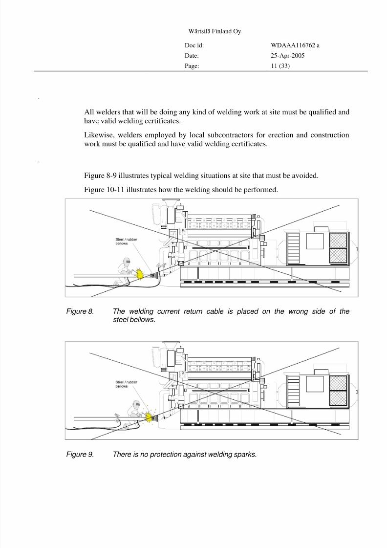
Weldingexamplesatsite
Figure 8-9 illustrates typical welding situations at site that must be avoided.
Figure 10-11 illustrates how the welding should be performed.
Figure 8. The welding current return cable is placed on the wrong side of the steel bellows.
Figure 9. There is no protection against welding sparks.
8/4/2019 Welding Installation Procedure
http://slidepdf.com/reader/full/welding-installation-procedure 12/33
Wärtsilä Finland Oy
Doc id: WDAAA116762 a
Date: 25-Apr-2005
Page: 12 (33)
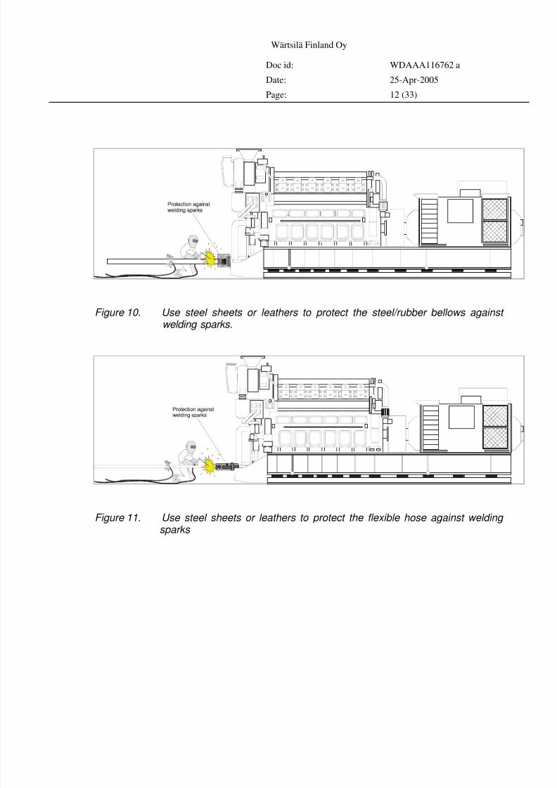
Figure 10. Use steel sheets or leathers to protect the steel/rubber bellows against welding sparks.
Figure 11. Use steel sheets or leathers to protect the flexible hose against welding sparks
8/4/2019 Welding Installation Procedure
http://slidepdf.com/reader/full/welding-installation-procedure 13/33
Wärtsilä Finland Oy
Doc id: WDAAA116762 a
Date: 25-Apr-2005
Page: 13 (33)
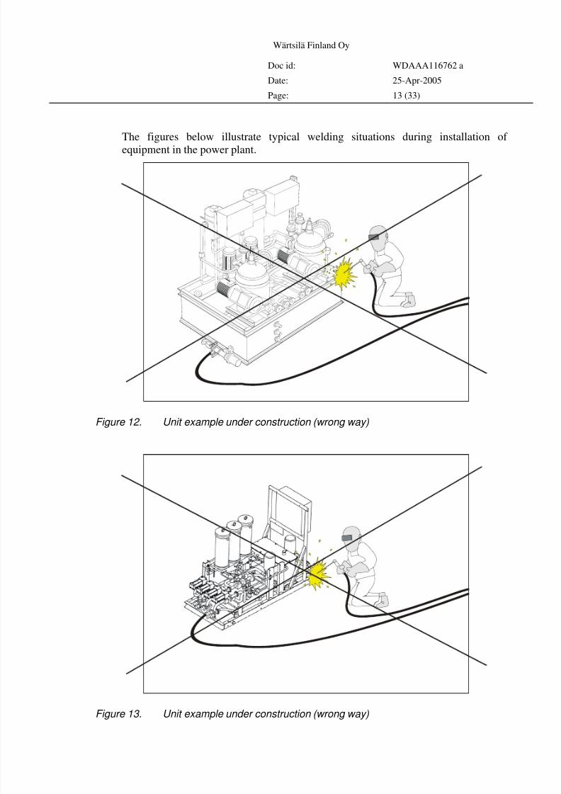
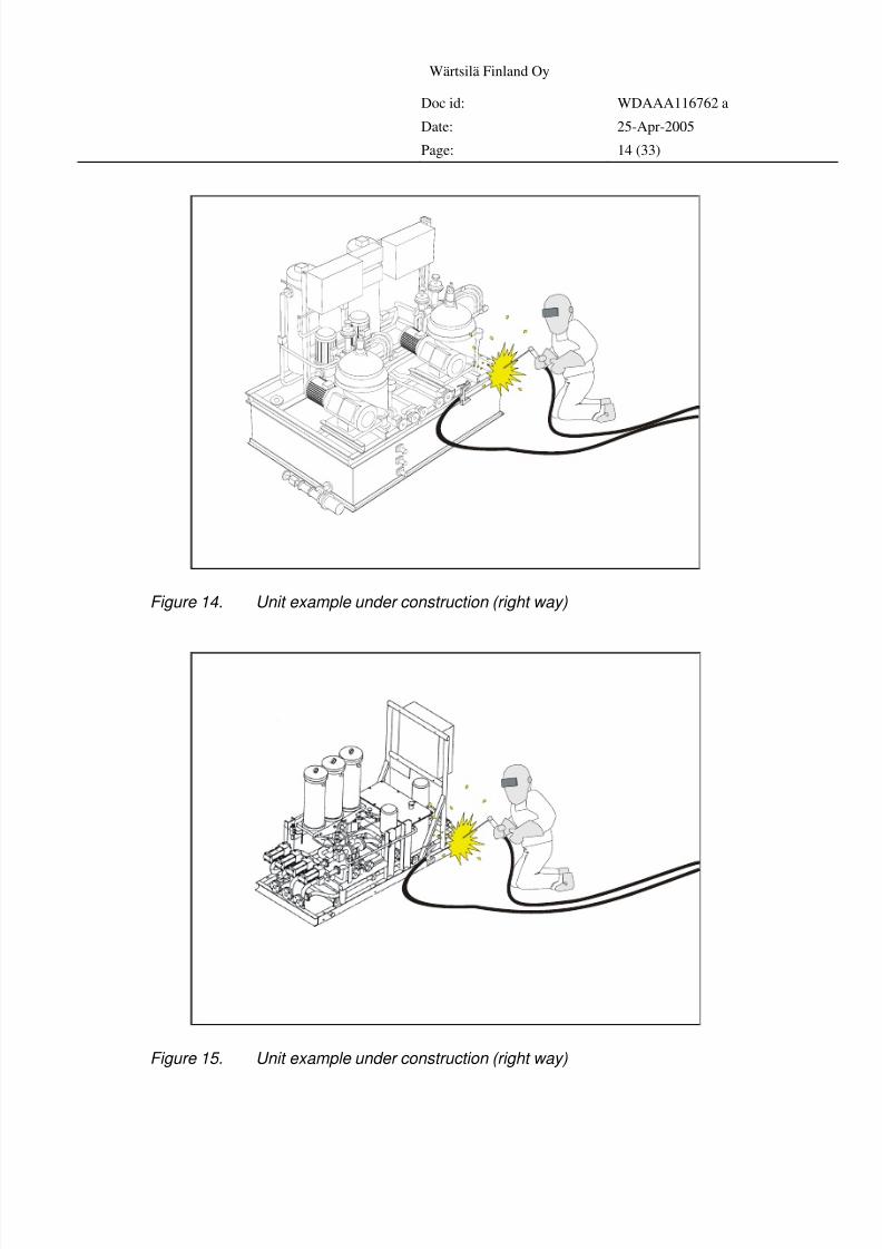
The figures below illustrate typical welding situations during installation of equipment in the power plant.
Figure 12. Unit example under construction (wrong way)
Figure 13. Unit example under construction (wrong way)
8/4/2019 Welding Installation Procedure
http://slidepdf.com/reader/full/welding-installation-procedure 14/33
Wärtsilä Finland Oy
Doc id: WDAAA116762 a
Date: 25-Apr-2005
Page: 14 (33)
Figure 14. Unit example under construction (right way)
Figure 15. Unit example under construction (right way)
8/4/2019 Welding Installation Procedure
http://slidepdf.com/reader/full/welding-installation-procedure 15/33
Wärtsilä Finland Oy
Doc id: WDAAA116762 a
Date: 25-Apr-2005
Page: 15 (33)
Selectionanduseof weldingconsumables
As a rule, the filler metal for hot-rolled steel is chosen with a chemical composition
corresponding to that of the base metal. For steels of high strength and toughness, the
filler metal must be alloyed to a higher degree than the base metal in order to
produce a weld metal with strength and notch toughness equal to those of the base
material. In practice, the type of filler metal is dictated by the required strength level
and impact strength class. Silicon + manganese alloyed filler metals are suitable for
the steel grades JR, J0, J2, KR, K0, K2, LR, L0 and L2 (EN 10025), up to approx.
400 N/mm2 yield strength, giving an acceptable level of weld metal impact strength
at temperatures down to -20 °C (quality classes J2, K2 and L2). Weld metal
produced by silicon + manganese alloyed MIG/MAG wires generally remains toughat testing temperatures as low as -40 °C. For steels of higher strength and for
structures requiring greater notch toughness, filler metals of higher alloy content, for
example Ni, Ni + Cu, Mo or Ni + Mo, must be used.
For hot-rolled steel, filler metals of equal or only slightly (5 to 10 %) higher strength
than the base material are recommended. Filler metals for pressure vessels are,
however, required to produce a weld metal that meets the required strength factor.
The use of highly overmatching filler metals results in increased residual stresses and
a greater danger of distortion and cracking.
In welding steels of the highest strength levels, such as RAEX 560 HSF, RAEX 640
HSF and RAEX 700 HSF, it is advisable to avoid welded joints in locations where
the structure is under greatest stress so that under matching filler metals that are
softer than the base material can be used.
For welding pressure vessel steels, the consumables must be chosen from among
those approved by the proper authority or classification society.
Welding consumables for weathering steels must obviously be selected to ensure that
the welds will also be weather resistant. Consequently, the filler metal composition
must be similar to that of the base material. Nickel and copper are the most common
alloy elements in filler metals for welding weathering steels. Unalloyed filler metal
can be used where the form of joint preparation (square groove, fillet weld) and thedegree of penetration (submerged arc welding) are such that the base material amply
mixes with the weld metal. In that case the filler metal takes up the necessary
alloying elements from molten base material. In the multi-run welding of weathering
steels, the final runs should always be made with weather resistant filler metal.
The choice of filler metal for RAEX B boron steel depends on whether the welding is
carried out prior to heat treatments or only after hardening and, possibly, tempering.
The general idea is that non-alloy or low-alloy “low-strength” filler metals (e.g. OK
48.00, OK Autrod 12.51) should be preferred even for boron steels. Low-strength
filler metals make welds that are less sensitive to cracking and require less
preheating. Higher-alloyed filler metals (e.g. OK 75.75, OK Autrod 13.12) can beused if the weld metal must be easily hard enable and hardening is not followed by
8/4/2019 Welding Installation Procedure
http://slidepdf.com/reader/full/welding-installation-procedure 16/33
Wärtsilä Finland Oy
Doc id: WDAAA116762 a
Date: 25-Apr-2005
Page: 16 (33)
tempering, or if weld metal is required with high strength (hardness) in the as-welded
condition. Normally, the use of such high-alloy filler metals can be limited to the
surface passes. With low-strength filler metals, the surface of the weld metal
becomes as hard as with high-alloy materials, only the hardening depth remains
smaller.Storageanddryingofweldingconsumables
The proper storage and handling of welding electrodes, fluxes and wires is important
specially if these are meant for high-strength steels. Thus the hydrogen content of the
filler metal can be kept low and hydrogen cracking prevented. Welding consumables
must be stored in a dry and heated space so that the rate of moisture absorption by
electrodes and fluxes is kept to a minimum. The risk of corrosion is clearly reduced
for wires that are stored in dry space. Rust layers bind up moisture causing the
release of hydrogen into the molten weld pool. Welding consumables are best kept in
their unopened, original packages.
Coated electrodes and fluxes must be re-dried (preferably immediately before use) if
they have been exposed to moisture during storage or in transit, or if relevant
welding regulations provide for the special treatment of the filler materials to be
used.
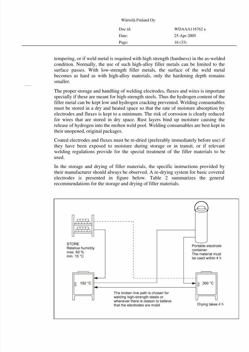
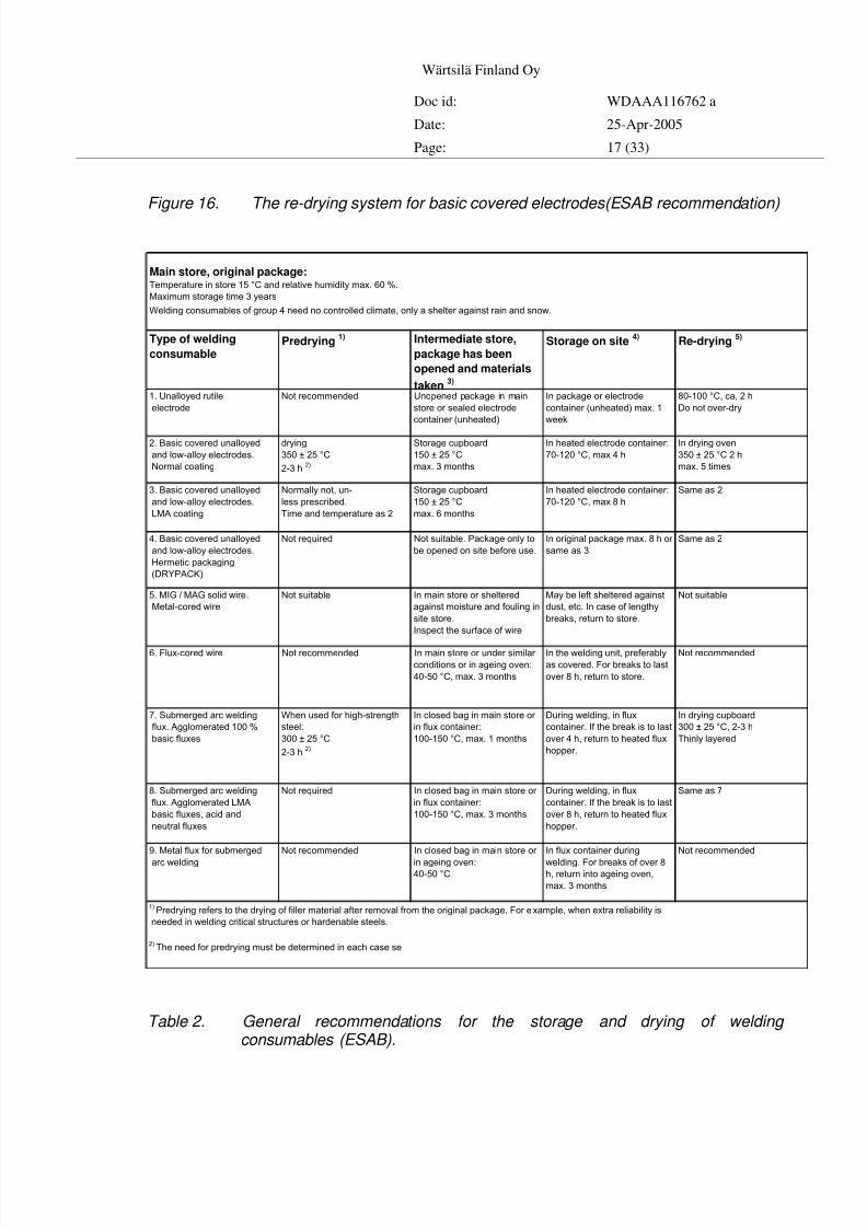
In the storage and drying of filler materials, the specific instructions provided by
their manufacturer should always be observed. A re-drying system for basic covered
electrodes is presented in figure below. Table 2 summarizes the general
recommendations for the storage and drying of filler materials.
8/4/2019 Welding Installation Procedure
http://slidepdf.com/reader/full/welding-installation-procedure 17/33
Wärtsilä Finland Oy
Doc id: WDAAA116762 a
Date: 25-Apr-2005
Page: 17 (33)
Figure 16. The re-drying system for basic covered electrodes(ESAB recommendation)
Type of welding
consumablePredrying
1) Intermediate store,
package has been
opened and materials
taken3)
Storage on site4)
Re-drying5)
1. Unalloyed rutile
electrode
Not recommended Unopened package in main
store or sealed electrode
container (unheated)
In package or electrode
container (unheated) max. 1
week
80-100 °C, ca, 2 h
Do not over-dry
2. Basic covered unalloyed
and low-alloy electrodes.
Normal coating
drying
350 ± 25 °C
2-3 h2)
Storage cupboard
150 ± 25 °C
max. 3 months
In heated electrode container:
70-120 °C, max 4 h
In drying oven
350 ± 25 °C 2 h
max. 5 times
3. Basic covered unalloyed
and low-alloy electrodes.
LMA coating
Normally not, un-
less prescribed.
Time and temperature as 2
Storage cupboard
150 ± 25 °C
max. 6 months
In heated electrode container:
70-120 °C, max 8 h
Same as 2
4. Basic covered unalloyed
and low-alloy electrodes.
Hermetic packaging
(DRYPACK)
Not required Not suitable. Package only to
be opened on site before use.
In original package max. 8 h or
same as 3
Same as 2
5. MIG / MAG solid wire.
Metal-cored wire
Not suitable In main store or sheltered
against moisture and fouling in
site store.
Inspect the surface of wire
May be left sheltered against
dust, etc. In case of lengthy
breaks, return to store.
Not suitable
6. Flux-cored wire Not recommended In main store or under similar
conditions or in ageing oven:
40-50 °C, max. 3 months
In the welding unit, preferably
as covered. For breaks to last
over 8 h, return to store.
Not recommended
7. Submerged arc welding
flux. Agglomerated 100 %
basic fluxes
When used for high-strength
steel:
300 ± 25 °C
2-3 h2)
In closed bag in main store or
in flux container:
100-150 °C, max. 1 months
During welding, in flux
container. If the break is to last
over 4 h, return to heated flux
hopper.
In drying cupboard
300 ± 25 °C, 2-3 h
Thinly layered
8. Submerged arc welding
flux. Agglomerated LMA
basic fluxes, acid and
neutral fluxes
Not required In closed bag in main store or
in flux container:
100-150 °C, max. 3 months
During welding, in flux
container. If the break is to last
over 8 h, return to heated flux
hopper.
Same as 7
9. Metal flux for submerged
arc welding
Not recommended In closed bag in main store or
in ageing oven:40-50 °C
In flux container during
welding. For breaks of over 8h, return into ageing oven,
max. 3 months
Not recommended
Main store, original package:Temperature in store 15 °C and relative humidity max. 60 %.
Maximum storage time 3 years
Welding consumables of group 4 need no controlled climate, only a shelter against rain and snow.
1)Predrying refers to the drying of filler material after removal from the original package. For example, when extra reliability is
needed in welding critical structures or hardenable steels.
2)The need for predrying must be determined in each case se
Table 2. General recommendations for the storage and drying of welding consumables (ESAB).
8/4/2019 Welding Installation Procedure
http://slidepdf.com/reader/full/welding-installation-procedure 18/33
Wärtsilä Finland Oy
Doc id: WDAAA116762 a
Date: 25-Apr-2005
Page: 18 (33)
Weldingr equir ements
Next tables shows usual acceptance levels for different defects in cooling water,
starting air, lube- and fuel oil pipes. Welding of district heating, steam and gas pipes
shall be done according to local and national pressure vessel requirements.Compliancewithnexttables
With the aid of the detailed requirements specified in next tables for welding defects,
both with regard to their nature and extent, the description of a generally applicable
quality level for each quality class is attempted. However, a danger of such a system
is that it may be implemented too pedantically.
The dimensions in Tables refer to:
s Nominal thickness of parent metal. Where the weld going
together materials of different thicknesses, this refers to
the smaller nominal thickness.
d Shortest distance between defects.
l Length of individual defect.
h Largest height or depth of defect in weld thickness direction.
b Width of (weld face) reinforcement.
8/4/2019 Welding Installation Procedure
http://slidepdf.com/reader/full/welding-installation-procedure 19/33
Wärtsilä Finland Oy
Doc id: WDAAA116762 a
Date: 25-Apr-2005
Page: 19 (33)
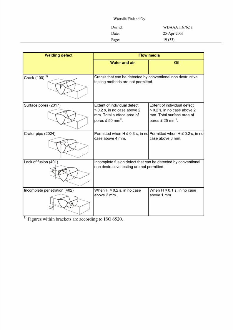
Acceptancelevelsforsurfaceandinternal defectsandimperfectshapeanddefectivegeometryof buttjoints.
Water and air Oil
Crack (100)1)
Surface pores (2017) Extent of individual defect
≤ 0.2 s, in no case above 2
mm. Total surface area of pores ≤ 50 mm
2.
Extent of individual defect
≤ 0.2 s, in no case above 2
mm. Total surface area of pores ≤ 25 mm
2.
Crater pipe (2024) Permitted when H ≤ 0.3 s, in no
case above 4 mm.
Permitted when H ≤ 0.2 s, in no
case above 3 mm.
Lack of fusion (401)
Incomplete penetration (402) When H ≤ 0.2 s, in no case
above 2 mm.
When H ≤ 0.1 s, in no case
above 1 mm.
Welding defect Flow media
Cracks that can be detected by conventional non destructive
testing methods are not permitted.
Incomplete fusion defect that can be detected by conventional
non destructive testing are not permitted.
1)
Figures within brackets are according to ISO 6520.
8/4/2019 Welding Installation Procedure
http://slidepdf.com/reader/full/welding-installation-procedure 20/33
Wärtsilä Finland Oy
Doc id: WDAAA116762 a
Date: 25-Apr-2005
Page: 20 (33)
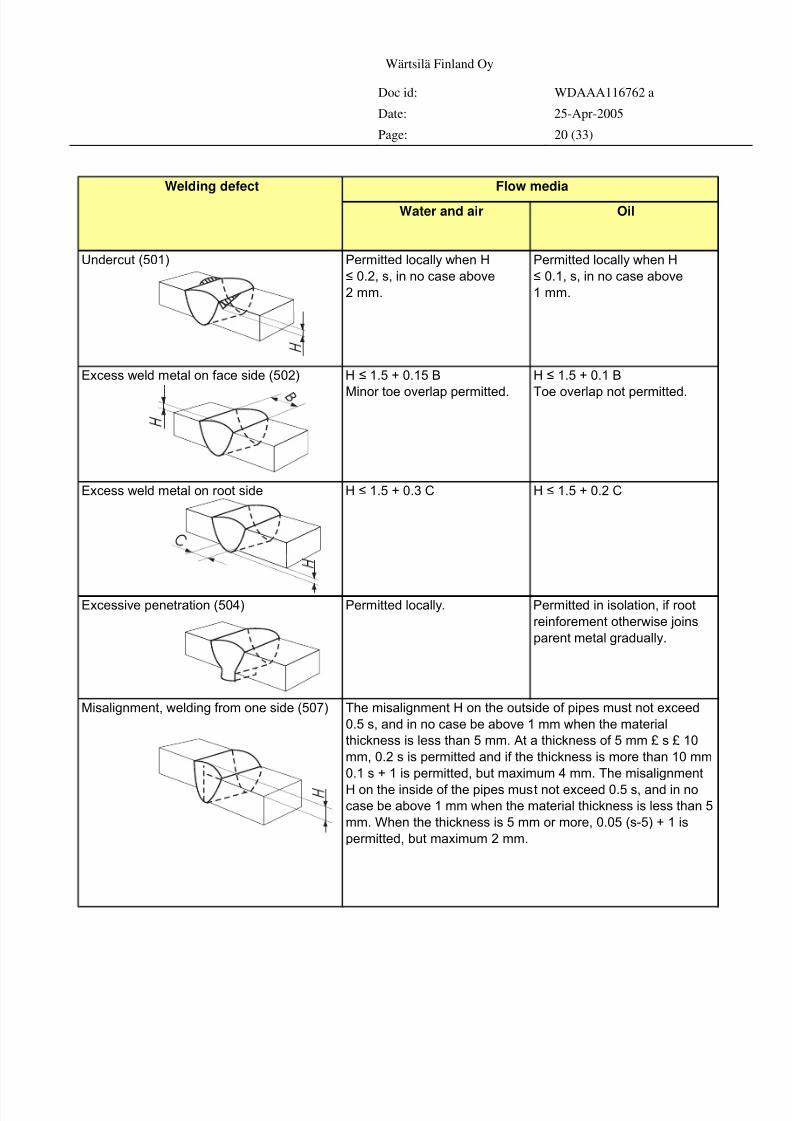
Water and air Oil
Undercut (501) Permitted locally when H
≤ 0.2, s, in no case above
2 mm.
Permitted locally when H
≤ 0.1, s, in no case above
1 mm.
Excess weld metal on face side (502) H ≤ 1.5 + 0.15 B
Minor toe overlap permitted.
H ≤ 1.5 + 0.1 B
Toe overlap not permitted.
Excess weld metal on root side H ≤ 1.5 + 0.3 C H ≤ 1.5 + 0.2 C
Excessive penetration (504) Permitted locally. Permitted in isolation, if root
reinforement otherwise joins
parent metal gradually.
Misalignment, welding from one side (507)
Welding defect Flow media
The misalignment H on the outside of pipes must not exceed
0.5 s, and in no case be above 1 mm when the material
thickness is less than 5 mm. At a thickness of 5 mm £ s £ 10
mm, 0.2 s is permitted and if the thickness is more than 10 mm
0.1 s + 1 is permitted, but maximum 4 mm. The misalignment
H on the inside of the pipes must not exceed 0.5 s, and in nocase be above 1 mm when the material thickness is less than 5
mm. When the thickness is 5 mm or more, 0.05 (s-5) + 1 is
permitted, but maximum 2 mm.
8/4/2019 Welding Installation Procedure
http://slidepdf.com/reader/full/welding-installation-procedure 21/33
Wärtsilä Finland Oy
Doc id: WDAAA116762 a
Date: 25-Apr-2005
Page: 21 (33)
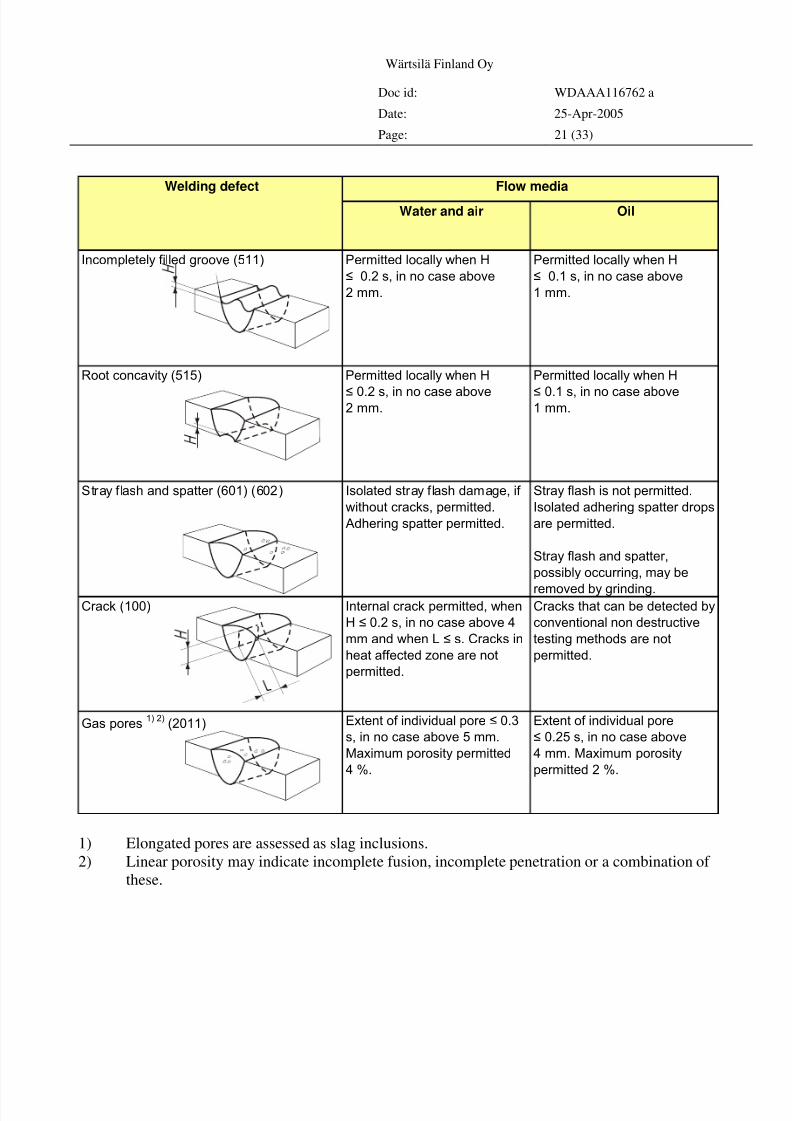
Water and air Oil
Incompletely filled groove (511) Permitted locally when H
≤ 0.2 s, in no case above
2 mm.
Permitted locally when H
≤ 0.1 s, in no case above
1 mm.
Root concavity (515) Permitted locally when H
≤ 0.2 s, in no case above2 mm.
Permitted locally when H
≤ 0.1 s, in no case above1 mm.
Stray flash and spatter (601) (602) Isolated stray flash damage, if
without cracks, permitted.
Adhering spatter permitted.
Stray flash is not permitted.
Isolated adhering spatter drops
are permitted.
Stray flash and spatter,
possibly occurring, may be
removed by grinding.Crack (100) Internal crack permitted, when
H ≤ 0.2 s, in no case above 4
mm and when L ≤ s. Cracks in
heat affected zone are not
permitted.
Cracks that can be detected by
conventional non destructive
testing methods are not
permitted.
Gas pores1) 2)
(2011) Extent of individual pore ≤ 0.3
s, in no case above 5 mm.
Maximum porosity permitted
4 %.
Extent of individual pore
≤ 0.25 s, in no case above
4 mm. Maximum porosity
permitted 2 %.
Welding defect Flow media
1) Elongated pores are assessed as slag inclusions.
2) Linear porosity may indicate incomplete fusion, incomplete penetration or a combination of
these.
8/4/2019 Welding Installation Procedure
http://slidepdf.com/reader/full/welding-installation-procedure 22/33
Wärtsilä Finland Oy
Doc id: WDAAA116762 a
Date: 25-Apr-2005
Page: 22 (33)
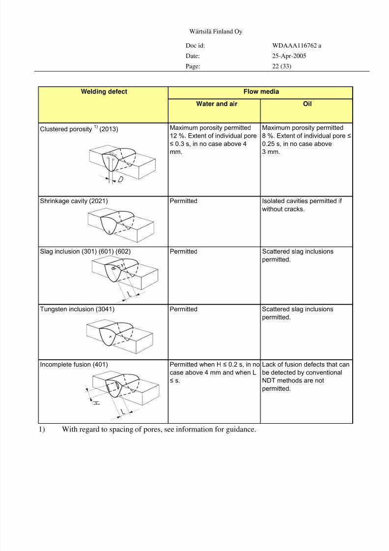
Water and air Oil
Clustered porosity1)
(2013) Maximum porosity permitted
12 %. Extent of individual pore
≤ 0.3 s, in no case above 4
mm.
Maximum porosity permitted
8 %. Extent of individual pore ≤
0.25 s, in no case above
3 mm.
Shrinkage cavity (2021) Permitted Isolated cavities permitted if
without cracks.
Slag inclusion (301) (601) (602) Permitted Scattered slag inclusions
permitted.
Tungsten inclusion (3041) Permitted Scattered slag inclusions
permitted.
Incomplete fusion (401) Permitted when H ≤ 0.2 s, in no
case above 4 mm and when L
≤ s.
Lack of fusion defects that can
be detected by conventional
NDT methods are not
permitted.
Welding defect Flow media
1) With regard to spacing of pores, see information for guidance.
8/4/2019 Welding Installation Procedure
http://slidepdf.com/reader/full/welding-installation-procedure 23/33
Wärtsilä Finland Oy
Doc id: WDAAA116762 a
Date: 25-Apr-2005
Page: 23 (33)
Endpr epar ationandcleaning
Cleaning
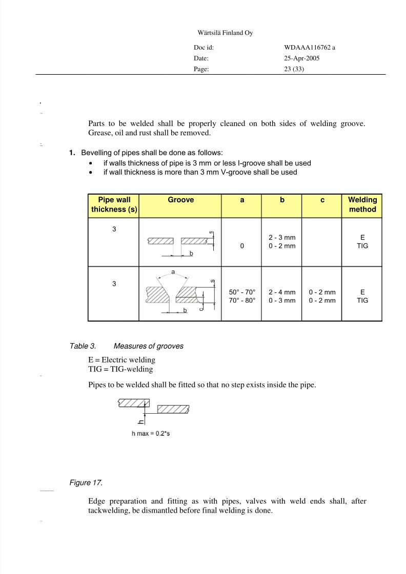
Parts to be welded shall be properly cleaned on both sides of welding groove.
Grease, oil and rust shall be removed.Pipes
Bevelling
1. Bevelling of pipes shall be done as follows:
• if walls thickness of pipe is 3 mm or less I-groove shall be used
• if wall thickness is more than 3 mm V-groove shall be used
Pipe wallthickness (s)
Groove a b c Weldingmethod
3
0
2 - 3 mm
0 - 2 mm
E
TIG
3
50° - 70°
70° - 80°
2 - 4 mm
0 - 3 mm
0 - 2 mm
0 - 2 mm
E
TIG
b
b c
s
a
Table 3. Measures of grooves
E = Electric welding
TIG = TIG-weldingFitting
Pipes to be welded shall be fitted so that no step exists inside the pipe.
Figure 17.Elbows,reducers,caps,teesandvalves withweldends
Edge preparation and fitting as with pipes, valves with weld ends shall, aftertackwelding, be dismantled before final welding is done.
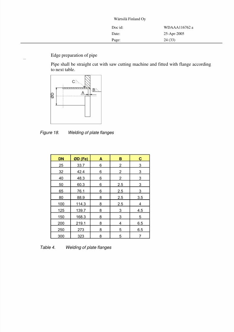
Flanges
8/4/2019 Welding Installation Procedure
http://slidepdf.com/reader/full/welding-installation-procedure 24/33
8/4/2019 Welding Installation Procedure
http://slidepdf.com/reader/full/welding-installation-procedure 25/33
Wärtsilä Finland Oy
Doc id: WDAAA116762 a
Date: 25-Apr-2005
Page: 25 (33)
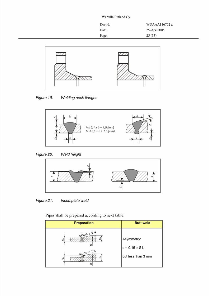
Figure 19. Welding neck flanges
Figure 20. Weld height
Figure 21. Incomplete weld
Pipes shall be prepared according to next table.
Preparation Butt weld
Asymmetry:
e < 0.15 × S1,
but less than 3 mm
s l o p e 1 : 4 £
s l o p e 1 : 4 £
s 2
s 2
e
e
s 1
s
1
8/4/2019 Welding Installation Procedure
http://slidepdf.com/reader/full/welding-installation-procedure 26/33
Wärtsilä Finland Oy
Doc id: WDAAA116762 a
Date: 25-Apr-2005
Page: 26 (33)
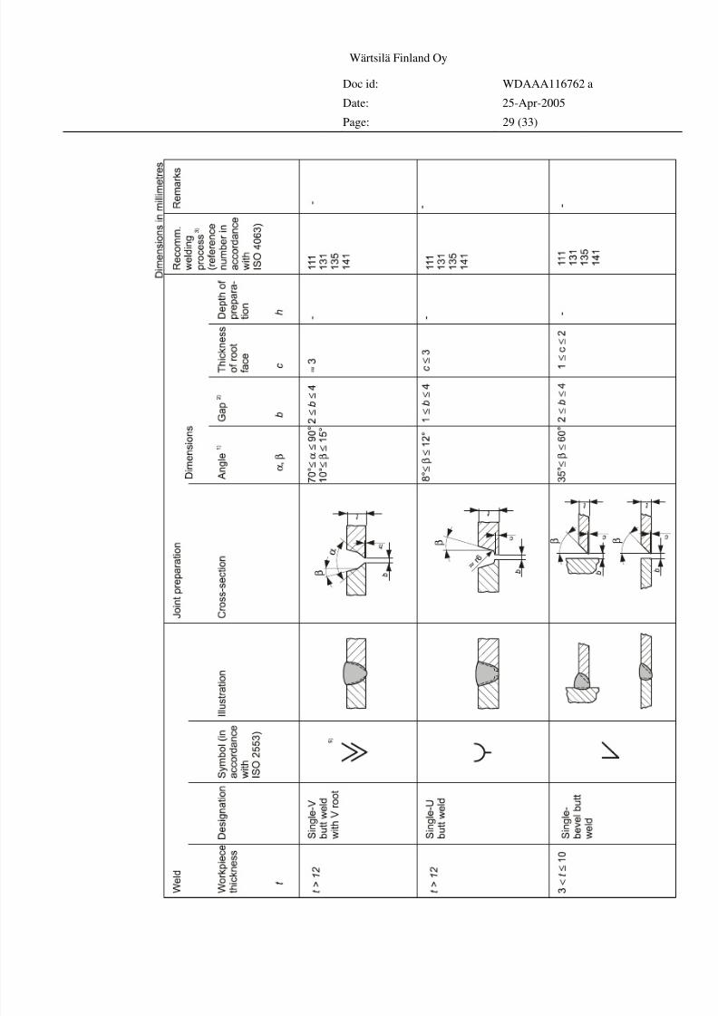
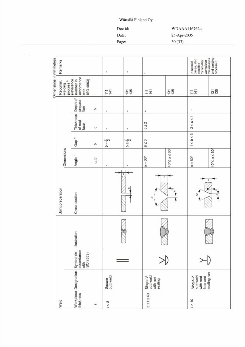
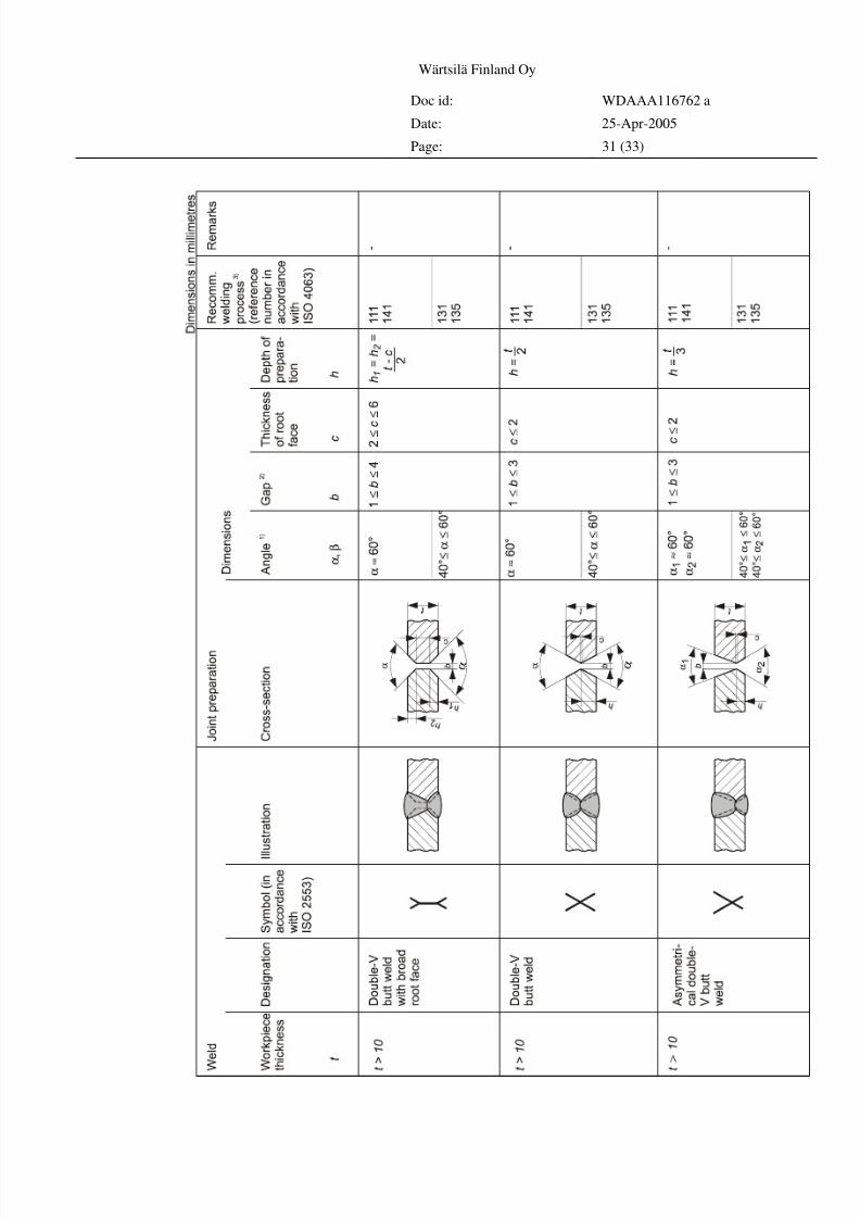
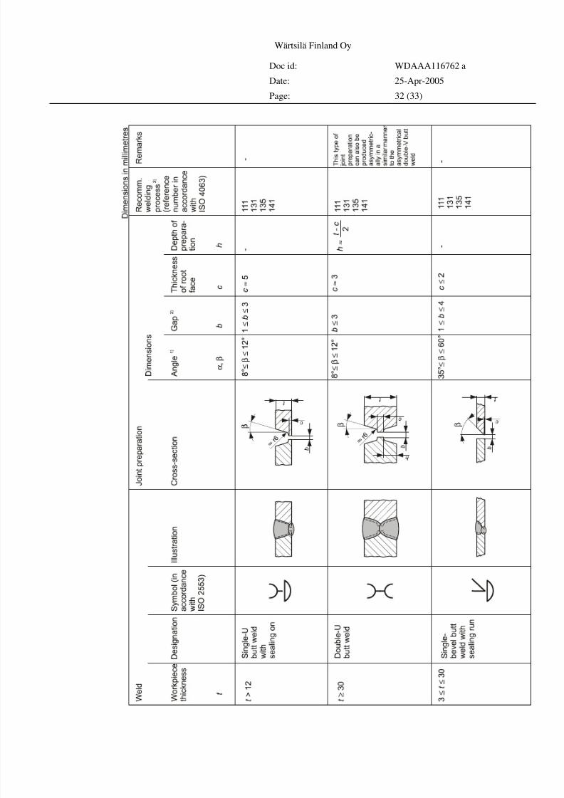
Jointpreparationsforbutt welds
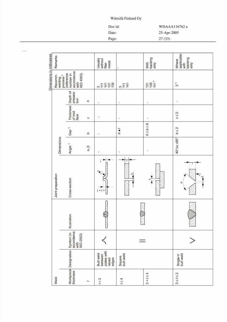
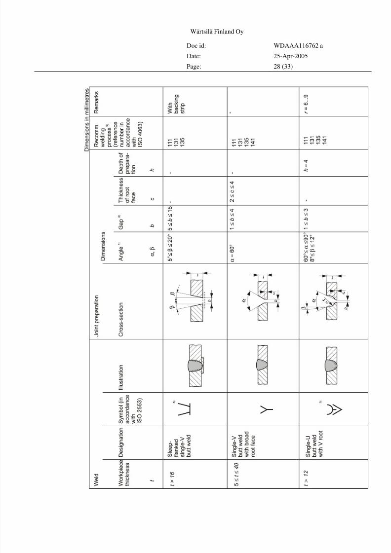
The tables on the next pages specify the joint preparations and recommended
welding processes for butt welds.
All dimensions are given in millimetres.
Explanation of notes:
1) Angles are also larger and/or asymmetric for welding in position PC
according to ISO 6947 (horizontal position).
2) Dimensions given apply to the tacked condition.
3) The indication of the welding process does not mean that it is applicable for
the whole range of work piece thicknesses.4) Applicable for 111, 131, 135, 141.
5) Symbol not yet standardized in ISO 2553.
8/4/2019 Welding Installation Procedure
http://slidepdf.com/reader/full/welding-installation-procedure 27/33
Wärtsilä Finland Oy
Doc id: WDAAA116762 a
Date: 25-Apr-2005
Page: 27 (33)
Buttweldsweldedfromoneside
8/4/2019 Welding Installation Procedure
http://slidepdf.com/reader/full/welding-installation-procedure 28/33
Wärtsilä Finland Oy
Doc id: WDAAA116762 a
Date: 25-Apr-2005
Page: 28 (33)
8/4/2019 Welding Installation Procedure
http://slidepdf.com/reader/full/welding-installation-procedure 29/33
Wärtsilä Finland Oy
Doc id: WDAAA116762 a
Date: 25-Apr-2005
Page: 29 (33)
8/4/2019 Welding Installation Procedure
http://slidepdf.com/reader/full/welding-installation-procedure 30/33
Wärtsilä Finland Oy
Doc id: WDAAA116762 a
Date: 25-Apr-2005
Page: 30 (33)
Buttweldsweldedfrombothsides
8/4/2019 Welding Installation Procedure
http://slidepdf.com/reader/full/welding-installation-procedure 31/33
Wärtsilä Finland Oy
Doc id: WDAAA116762 a
Date: 25-Apr-2005
Page: 31 (33)
8/4/2019 Welding Installation Procedure
http://slidepdf.com/reader/full/welding-installation-procedure 32/33
Wärtsilä Finland Oy
Doc id: WDAAA116762 a
Date: 25-Apr-2005
Page: 32 (33)
8/4/2019 Welding Installation Procedure
http://slidepdf.com/reader/full/welding-installation-procedure 33/33
Wärtsilä Finland Oy
Doc id: WDAAA116762 a
Date: 25-Apr-2005
Page: 33 (33)
Branches
Edgepreparation
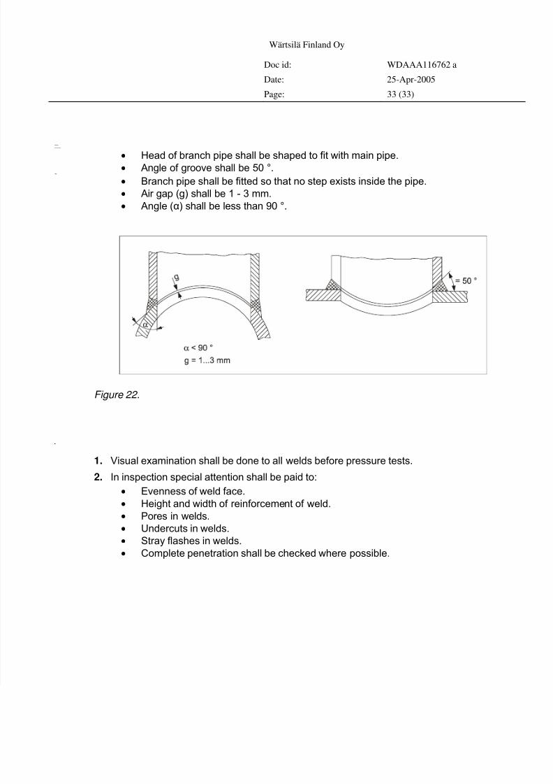
• Head of branch pipe shall be shaped to fit with main pipe.
• Angle of groove shall be 50 °.Fitting
• Branch pipe shall be fitted so that no step exists inside the pipe.
• Air gap (g) shall be 1 - 3 mm.
• Angle (α) shall be less than 90 °.
Figure 22.
Inspectionof welds
1. Visual examination shall be done to all welds before pressure tests.
2. In inspection special attention shall be paid to:
• Evenness of weld face.
• Height and width of reinforcement of weld.
• Pores in welds.
• Undercuts in welds.
• Stray flashes in welds.
• Complete penetration shall be checked where possible.