welding inspection - xa.yimg.comxa.yimg.com/kq/groups/8128318/1647381890/name... · bs en 22553...
TRANSCRIPT

Welding InspectionTerms & Definitions
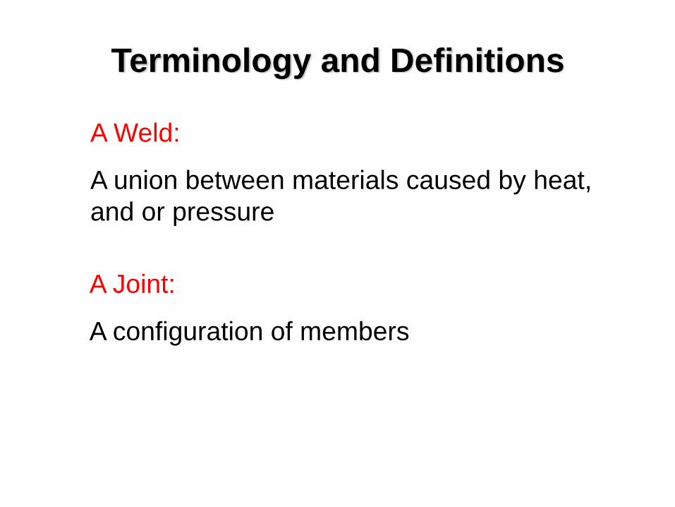
A Joint:
A configuration of members
A Weld:
A union between materials caused by heat, and or pressure
Terminology and Definitions
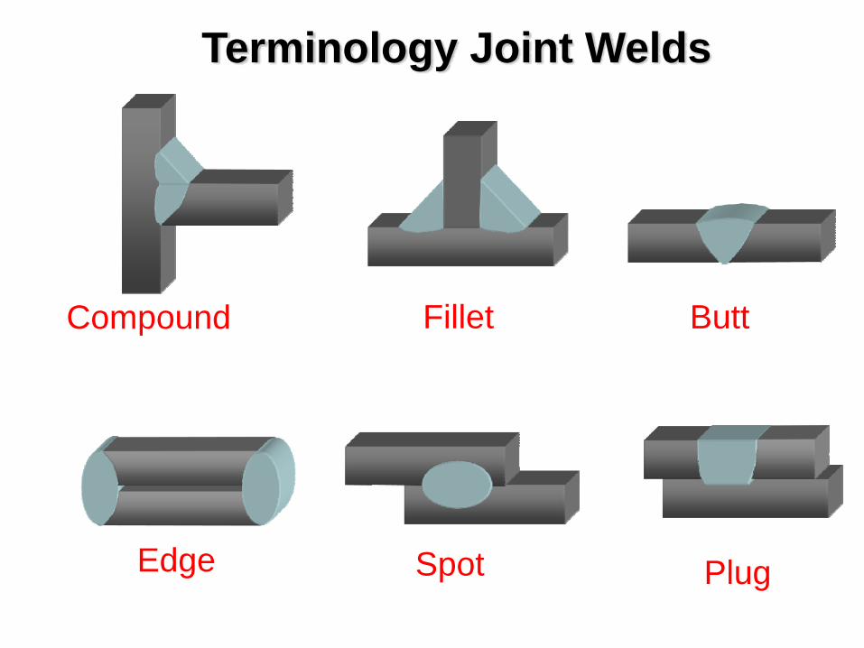
Terminology Joint Welds
Compound Fillet Butt
Edge Spot Plug
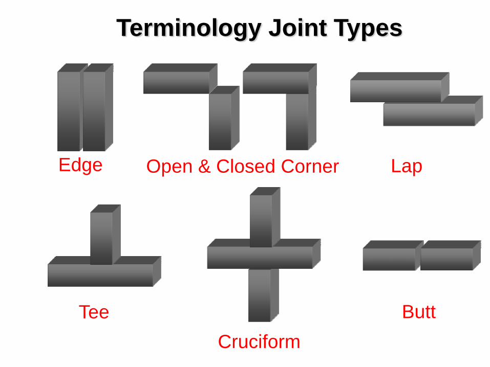
Terminology Joint Types
Edge Open & Closed Corner Lap
TeeCruciform
Butt
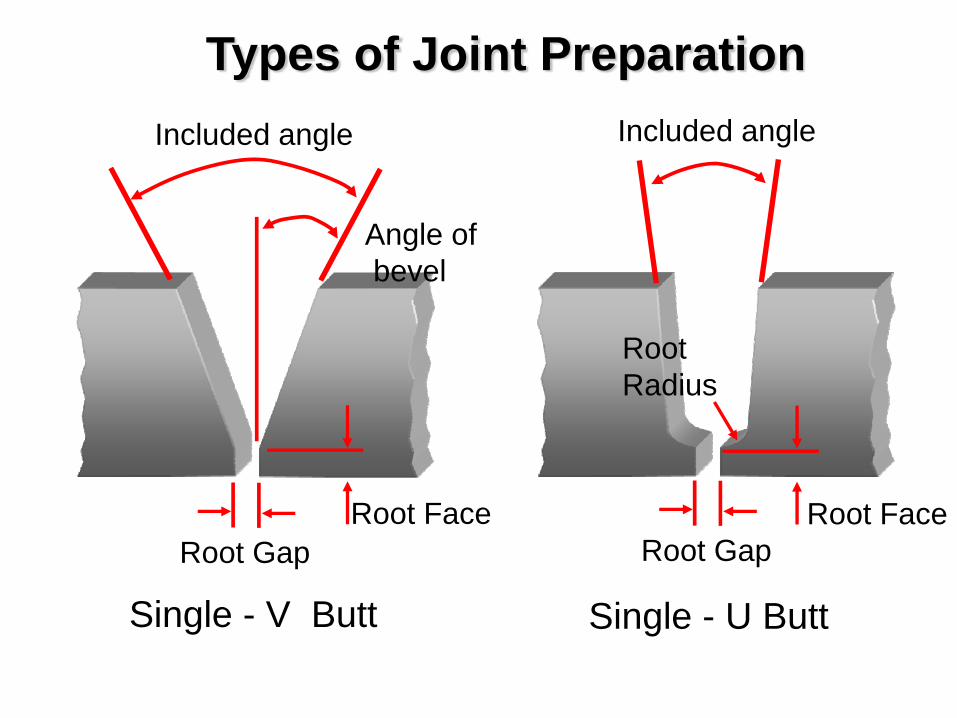
Types of Joint PreparationIncluded angle
Root GapRoot Face
Angle ofbevel
Root FaceRoot Gap
Included angle
Root Radius
Single - V Butt Single - U Butt
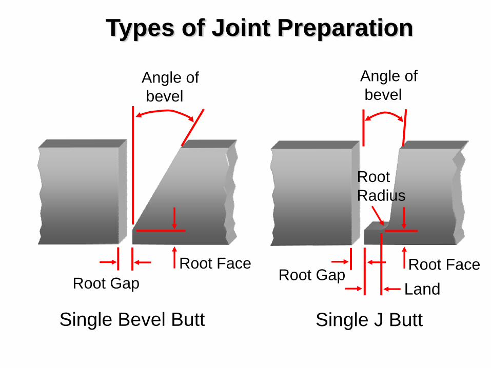
Root GapRoot Face Root Face
Root Gap
Root Radius
Single Bevel Butt Single J Butt
Angle ofbevel
Angle ofbevel
Land
Types of Joint Preparation
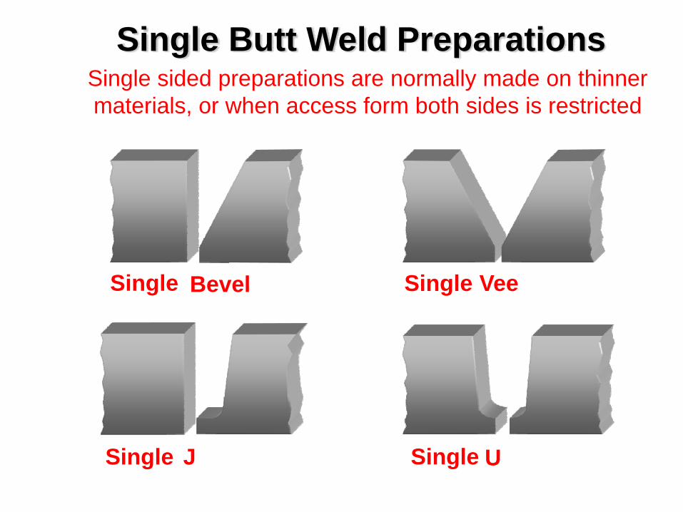
Single Butt Weld Preparations
Single Bevel VeeSingle
Single J Single U
Single sided preparations are normally made on thinner materials, or when access form both sides is restricted
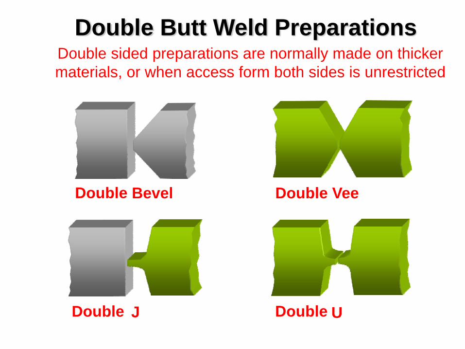
Double Butt Weld PreparationsDouble sided preparations are normally made on thicker materials, or when access form both sides is unrestricted
VeeDoubleBevelDouble
JDouble UDouble
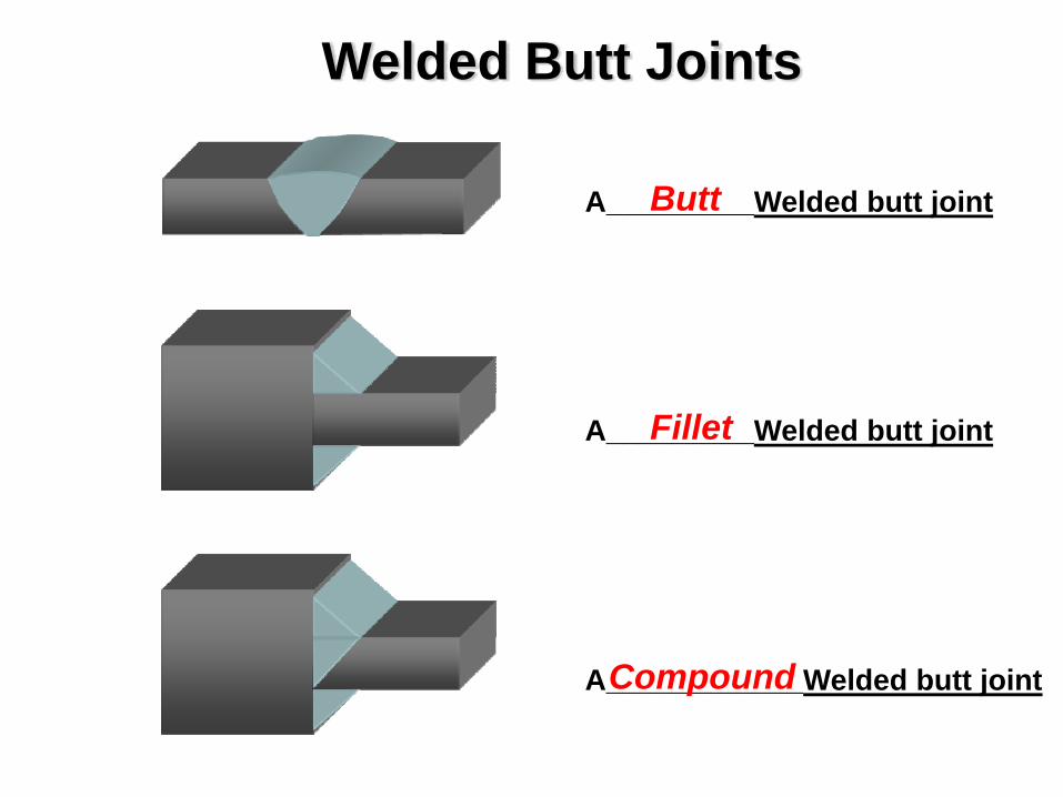
A_________Welded butt jointButt
A_________Welded butt jointFillet
A____________Welded butt jointCompound
Welded Butt Joints
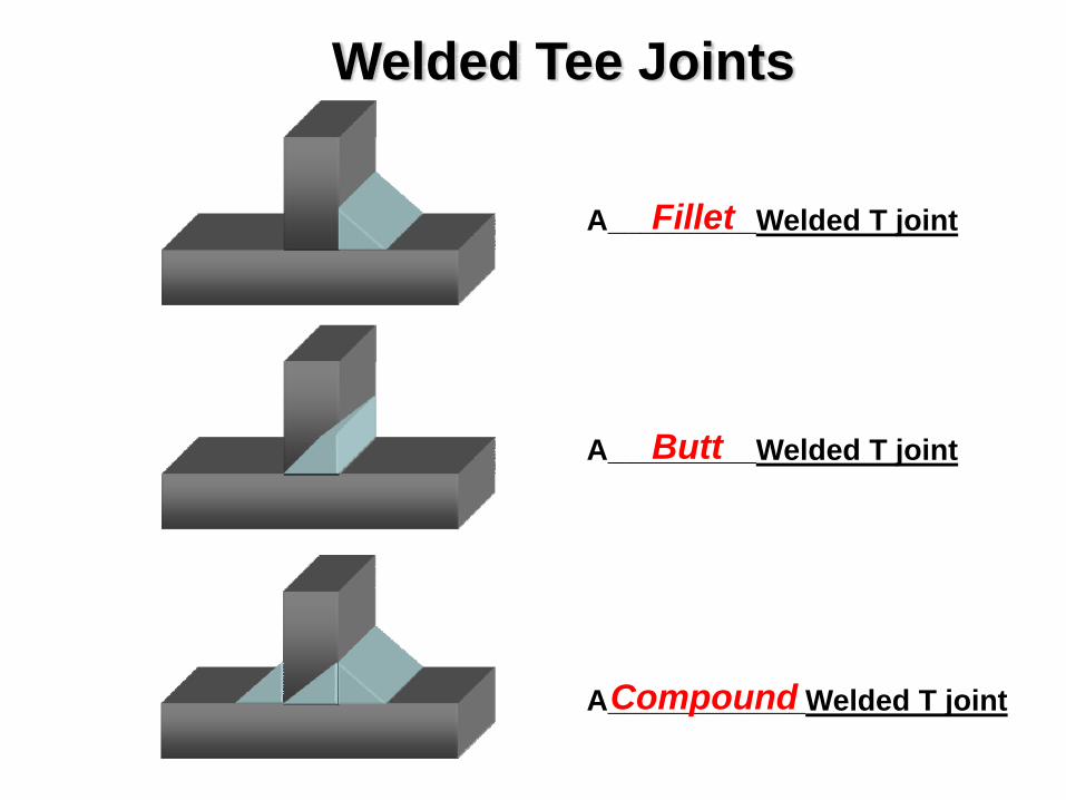
A_________Welded T jointFillet
A_________Welded T jointButt
A____________Welded T jointCompound
Welded Tee Joints
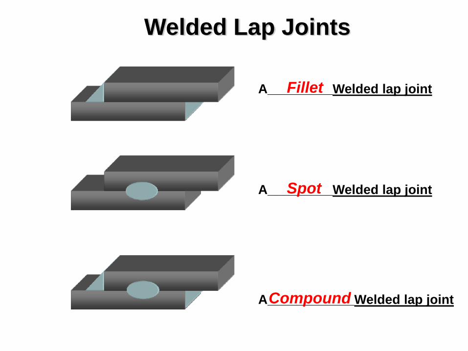
Welded Lap Joints
A_________Welded lap jointFillet
A_________Welded lap jointSpot
A____________Welded lap jointCompound
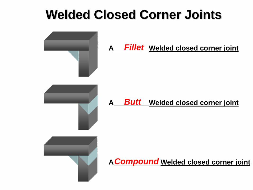
A_________Welded closed corner jointFillet
A_________Welded closed corner jointButt
A____________Welded closed corner jointCompound
Welded Closed Corner Joints
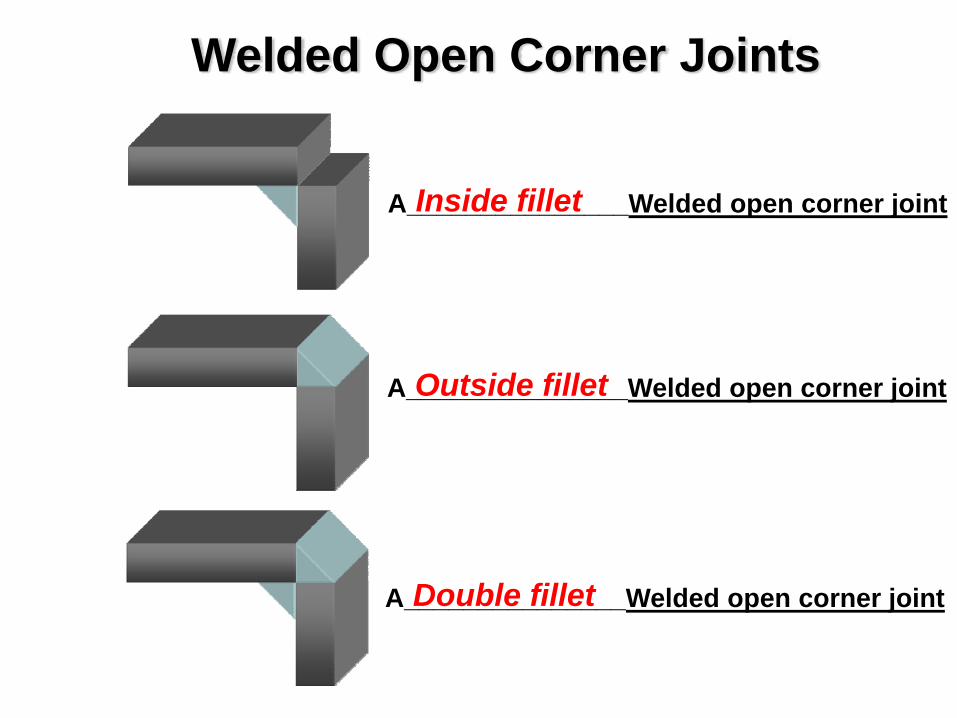
A_______________Welded open corner jointOutside fillet
Welded Open Corner Joints
A_______________Welded open corner jointInside fillet
A_______________Welded open corner jointDouble fillet
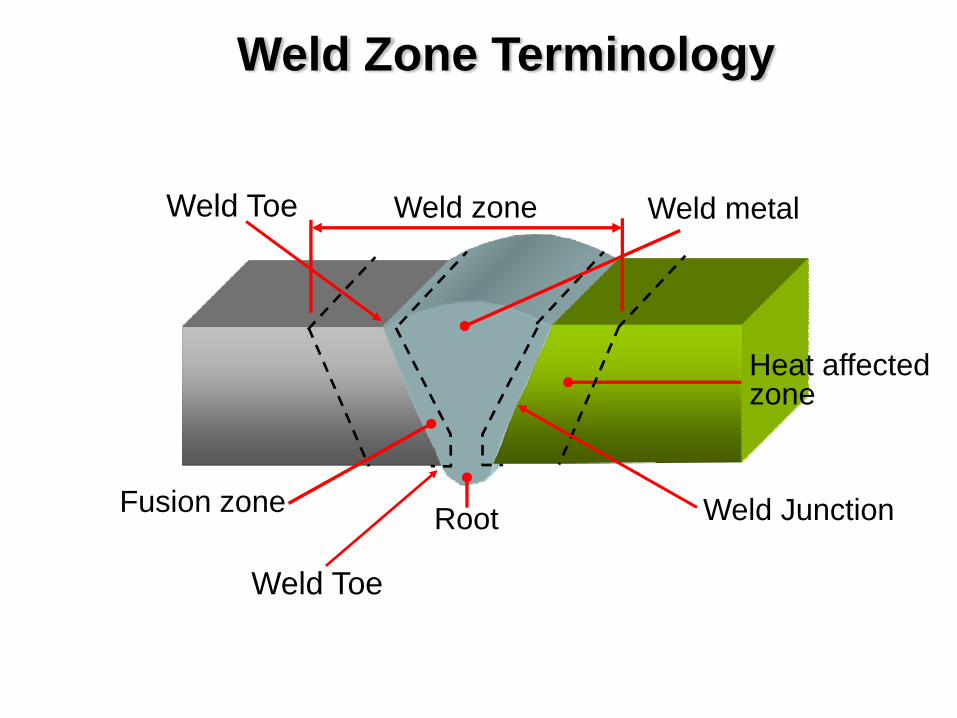
Weld Zone Terminology
Weld metal
RootFusion zone
Heat affectedzone
Weld zone
Weld Junction
Weld Toe
Weld Toe
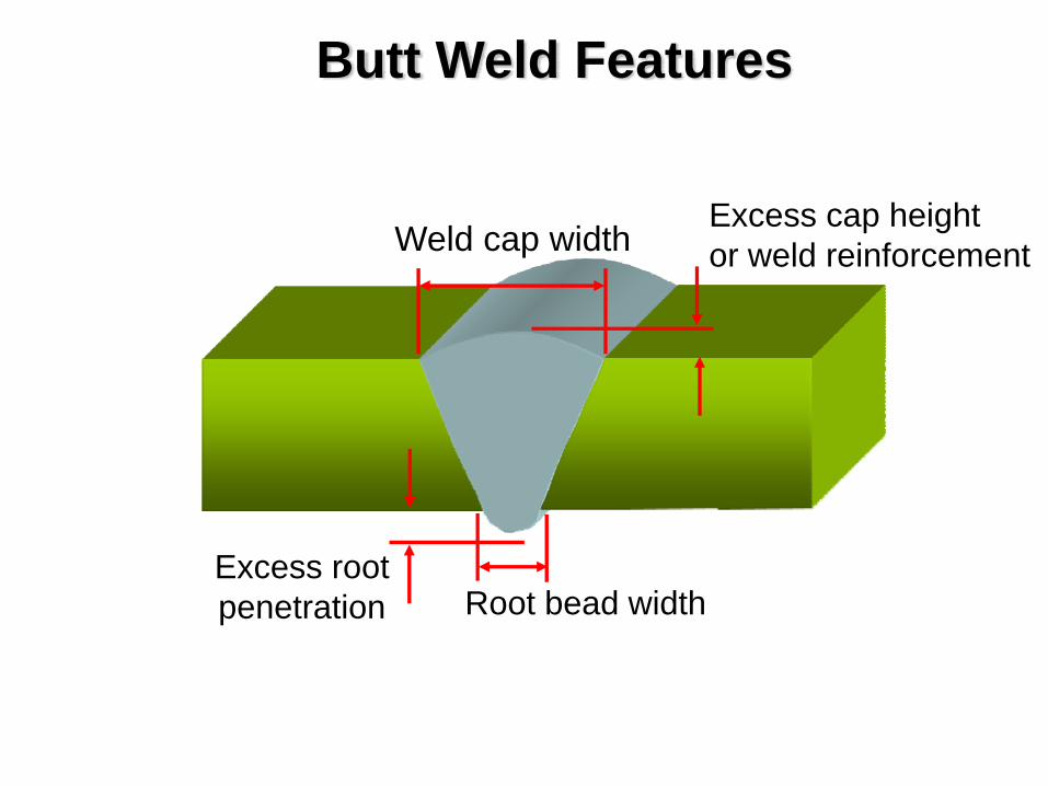
Butt Weld Features
Weld cap width
Excess root penetration Root bead width
Excess cap heightor weld reinforcement
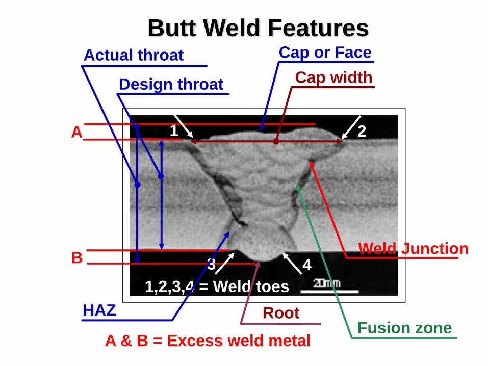
Butt Weld Features
A
B
A & B = Excess weld metal
Actual throat
1,2,3,4 = Weld toes
1 2
3 4
Cap or FaceCap widthDesign throat
Fusion zone
Weld Junction
HAZ Root
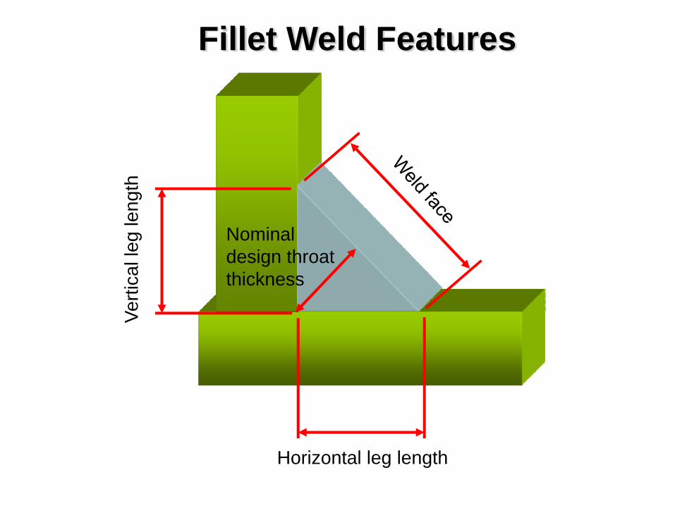
Fillet Weld Features
Horizontal leg length
Verti
cal l
eg le
ngth
Nominal design throat thickness
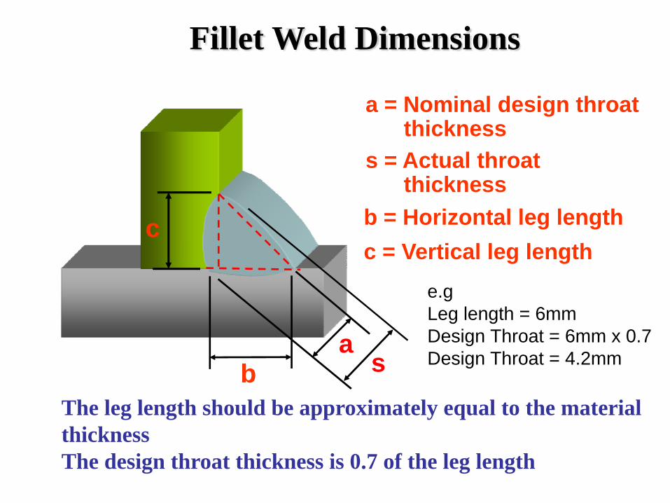
Fillet Weld Dimensions
a
a = Nominal design throat thickness
s
s = Actual throat thickness
b
b = Horizontal leg lengthcc = Vertical leg length
The leg length should be approximately equal to the material thicknessThe design throat thickness is 0.7 of the leg length
e.gLeg length = 6mmDesign Throat = 6mm x 0.7Design Throat = 4.2mm
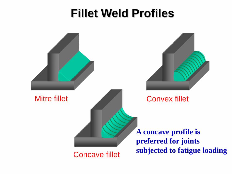
Fillet Weld Profiles
Mitre fillet Convex fillet
Concave fillet
A concave profile is preferred for joints subjected to fatigue loading
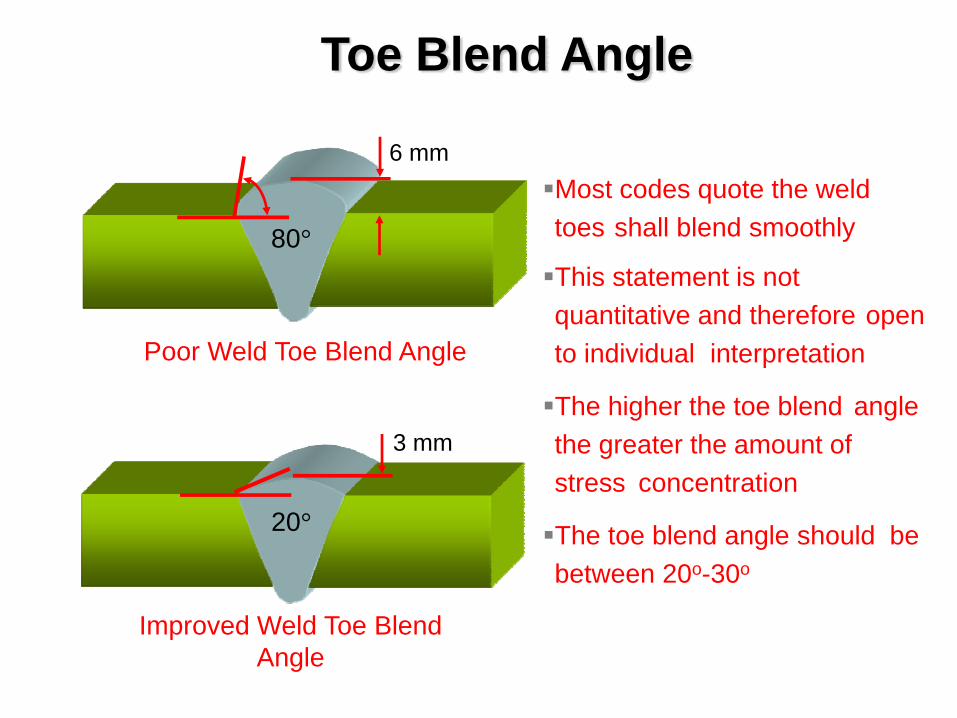
Toe Blend Angle
6 mm
80°
Poor Weld Toe Blend Angle
Improved Weld Toe Blend Angle
20°
3 mm
Most codes quote the weld toes shall blend smoothly
This statement is not quantitative and therefore open to individual interpretation
The higher the toe blend angle the greater the amount of stress concentration
The toe blend angle should be between 20o-30o
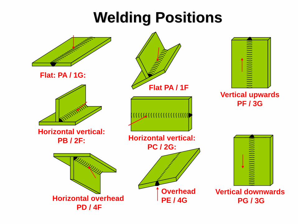
Flat: PA / 1G: Flat PA / 1F
Horizontal vertical: PC / 2G:
Horizontal vertical: PB / 2F:
Horizontal overheadPD / 4F
OverheadPE / 4G
Vertical downwardsPG / 3G
Vertical upwardsPF / 3G
Welding Positions
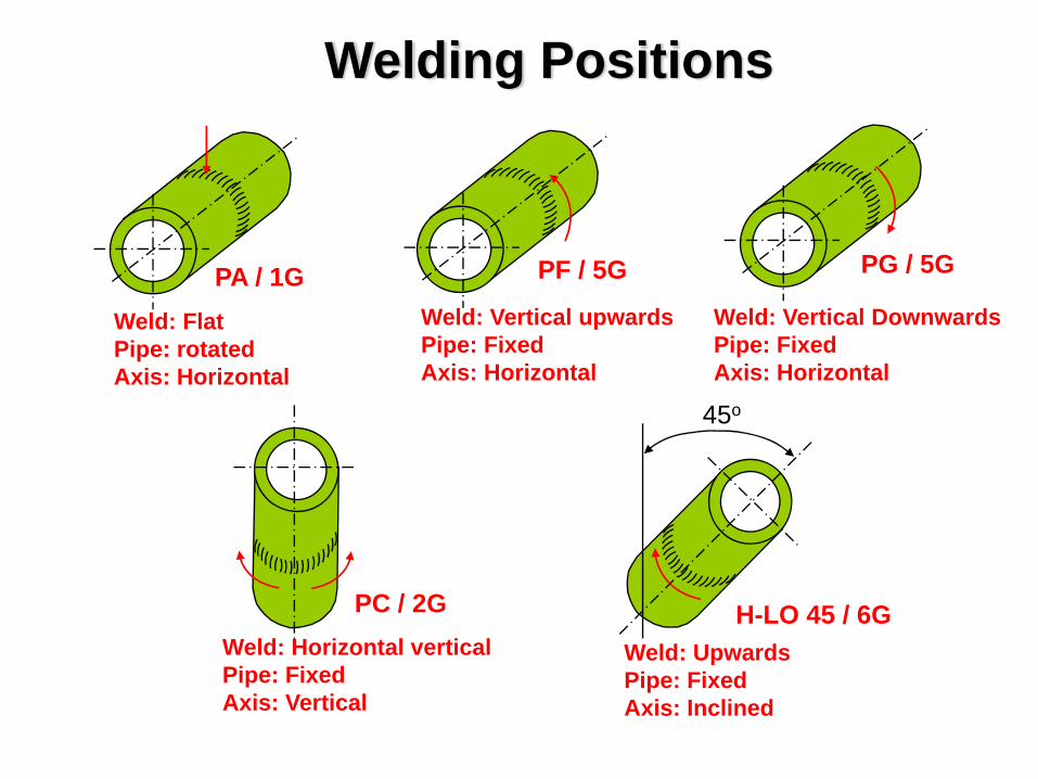
Weld: FlatPipe: rotatedAxis: Horizontal
PA / 1G Weld: Vertical DownwardsPipe: FixedAxis: Horizontal
PG / 5G
Weld: Vertical upwardsPipe: FixedAxis: Horizontal
PF / 5G
H-LO 45 / 6G Weld: Upwards Pipe: FixedAxis: Inclined
Weld: Horizontal vertical Pipe: FixedAxis: Vertical
PC / 2G
Welding Positions
45o

Any QuestionsAny Questions
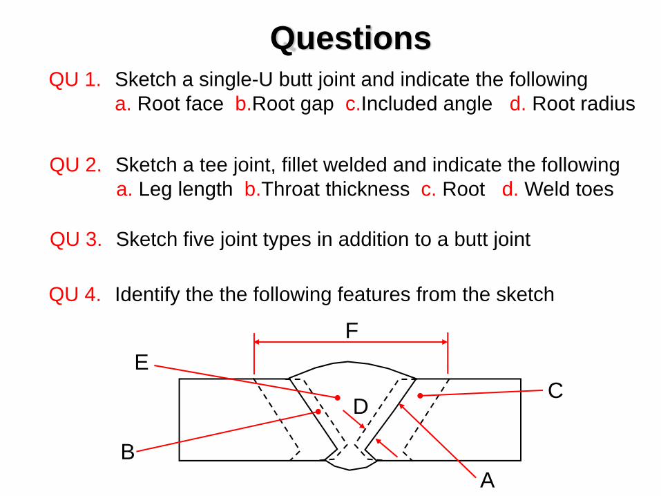
QuestionsQU 1. Sketch a single-U butt joint and indicate the following
a. Root face b.Root gap c.Included angle d. Root radius
QU 2. Sketch a tee joint, fillet welded and indicate the followinga. Leg length b.Throat thickness c. Root d. Weld toes
QU 3. Sketch five joint types in addition to a butt joint
QU 4. Identify the the following features from the sketch
EF
C
AB
D

Welding InspectionWelding Symbols
BS 499 part 2 Welding Symbols
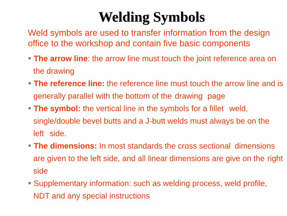
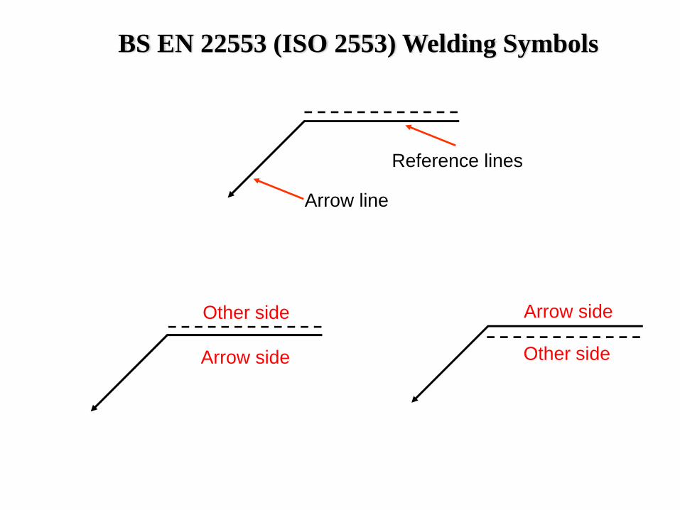
Welding SymbolsWeld symbols are used to transfer information from the design office to the workshop and contain five basic components
The arrow line: the arrow line must touch the joint reference area on the drawingThe reference line: the reference line must touch the arrow line and is generally parallel with the bottom of the drawing pageThe symbol: the vertical line in the symbols for a fillet weld, single/double bevel butts and a J-butt welds must always be on the left side.The dimensions: In most standards the cross sectional dimensions are given to the left side, and all linear dimensions are give on the right sideSupplementary information: such as welding process, weld profile, NDT and any special instructions
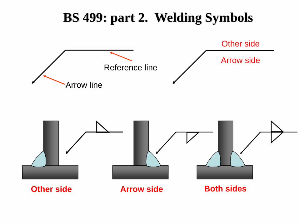
Arrow line
Reference lineArrow side
Other side
BS 499: part 2. Welding Symbols
Other side Arrow side Both sides
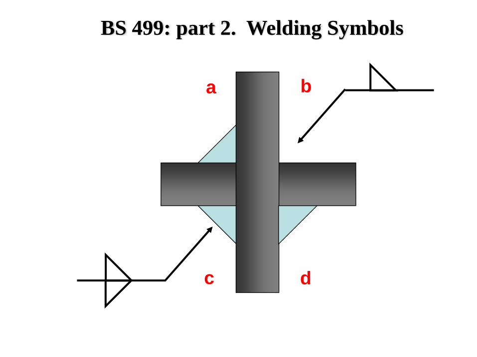
ba
dc
BS 499: part 2. Welding Symbols
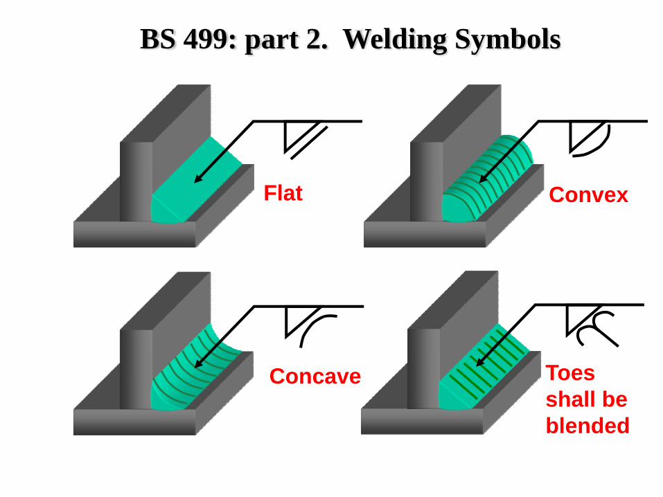
Toes shall be blended
Flat Convex
Concave
BS 499: part 2. Welding Symbols
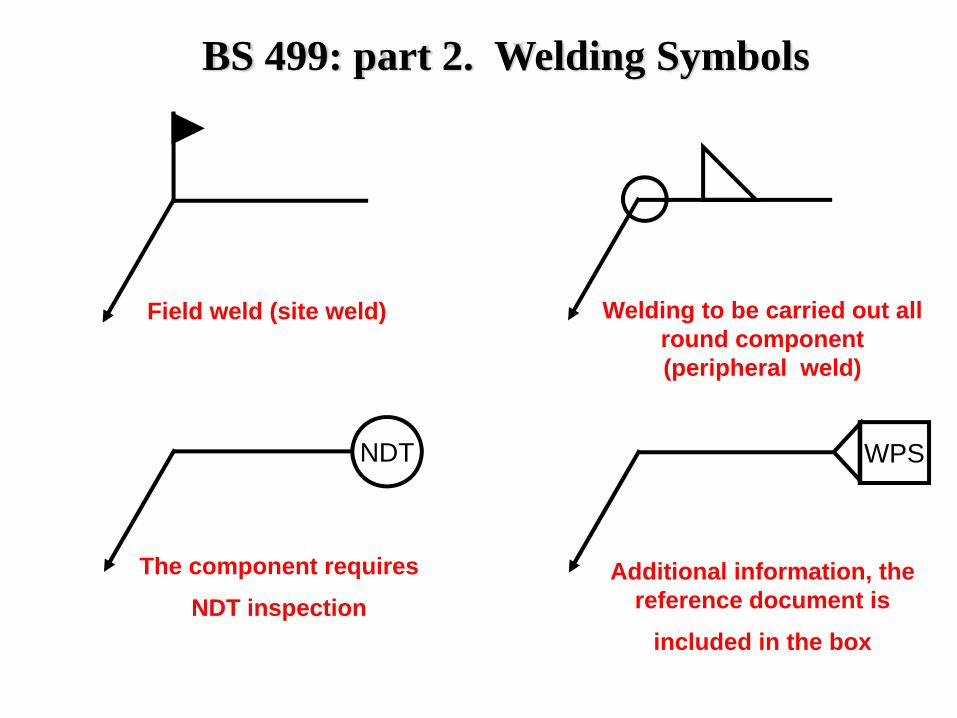
Field weld (site weld)
NDT
The component requires
NDT inspection
Welding to be carried out all round component (peripheral weld)
WPS
Additional information, the reference document is
included in the box
BS 499: part 2. Welding Symbols
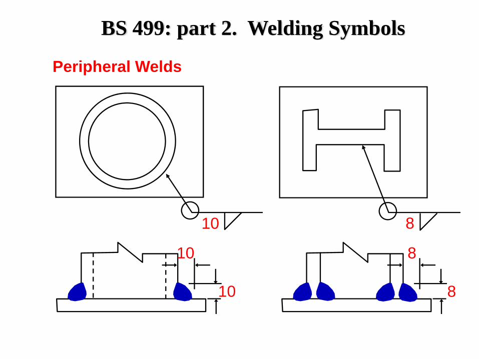
10 8
10
10
8
8
Peripheral Welds
BS 499: part 2. Welding Symbols
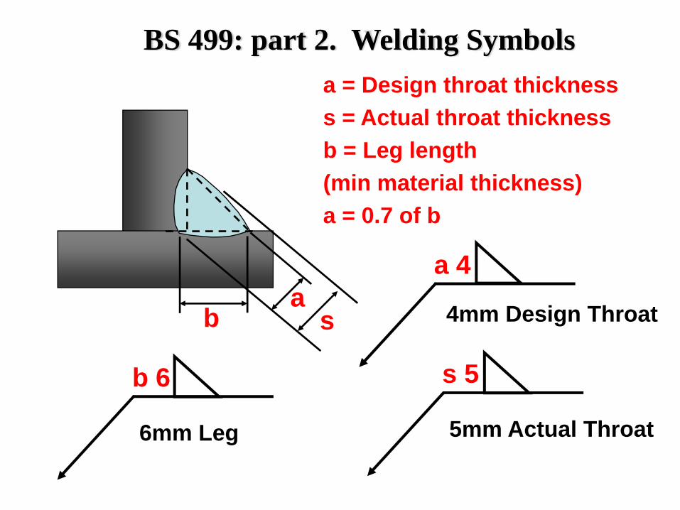
a = Design throat thicknesss = Actual throat thicknessb = Leg length (min material thickness)a = 0.7 of b
ab
a 4
4mm Design Throat
s 5
5mm Actual Throat
s
b 6
6mm Leg
BS 499: part 2. Welding Symbols
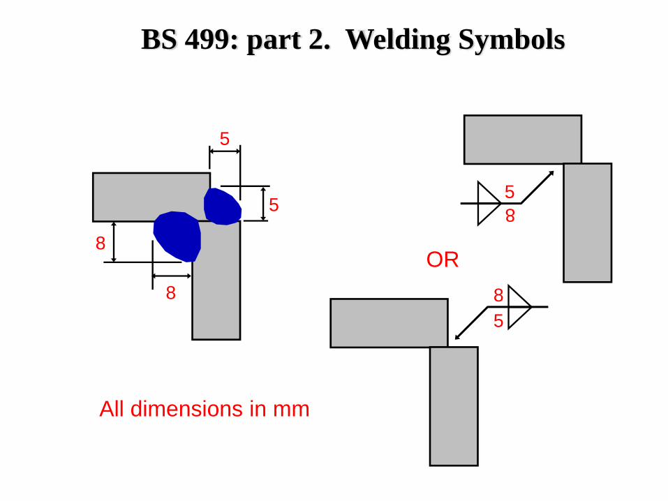
5
5
8
8
85
85
OR
All dimensions in mm
BS 499: part 2. Welding Symbols
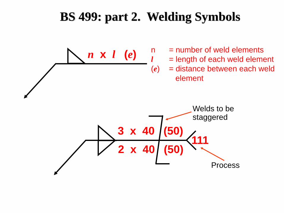
n x l (e) n = number of weld elementsl = length of each weld element(e) = distance between each weld
element
3 x 40 (50)2 x 40 (50)
111
Welds to be staggered
Process
BS 499: part 2. Welding Symbols
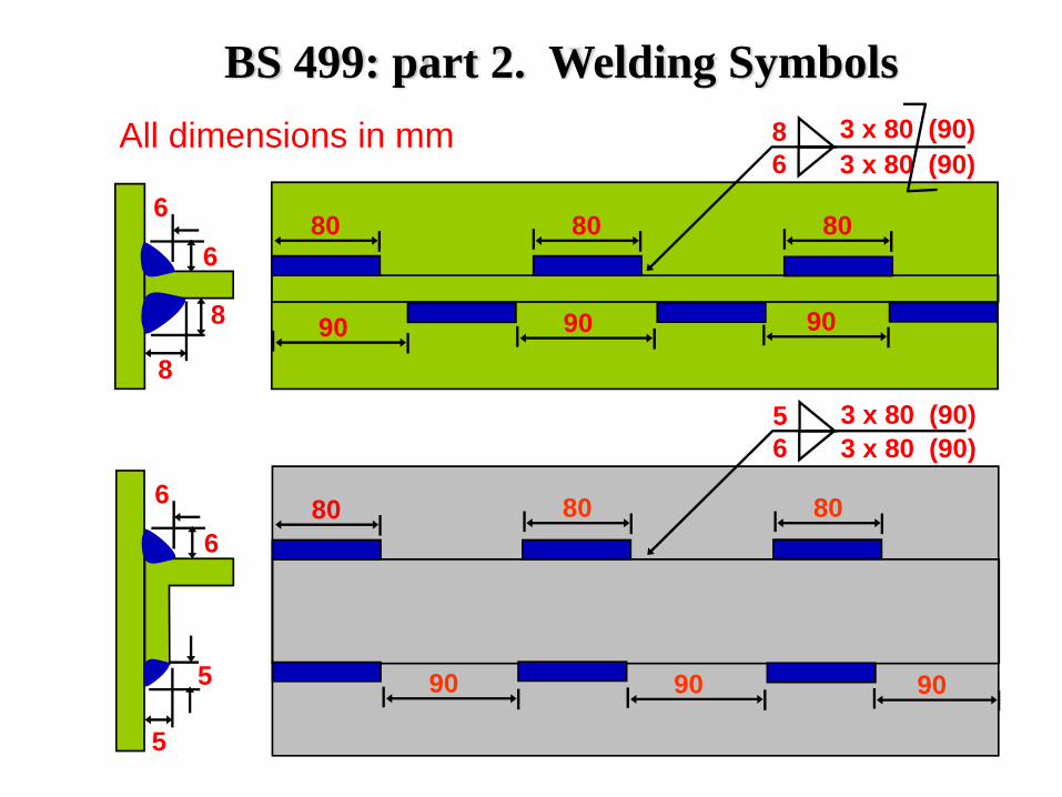
8
8
6
6
86
3 x 80 (90)3 x 80 (90)
80 80 80
909090
56
3 x 80 (90)3 x 80 (90)
80 80 80
909090
5
5
6
6
All dimensions in mm
BS 499: part 2. Welding Symbols
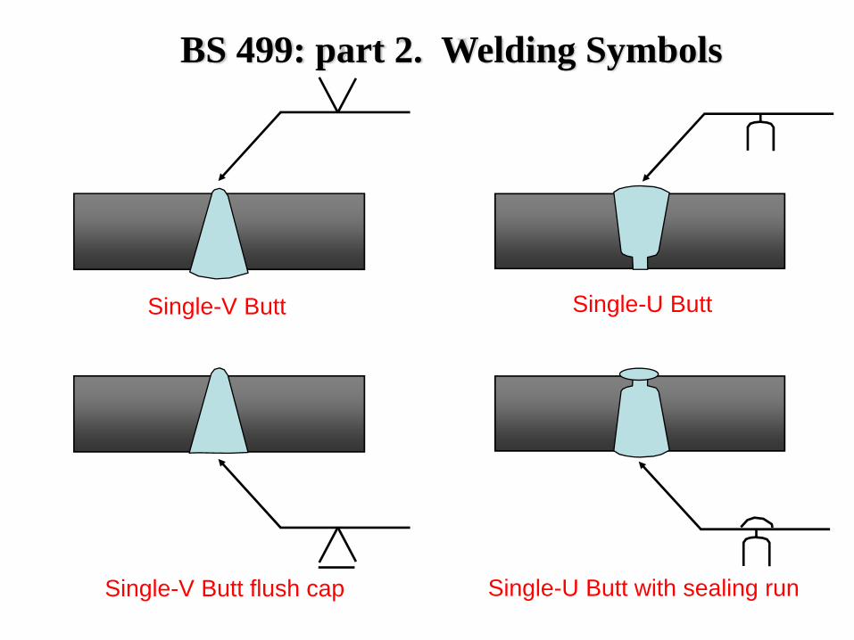
Single-V Butt Single-U Butt
Single-V Butt flush cap Single-U Butt with sealing run
BS 499: part 2. Welding Symbols
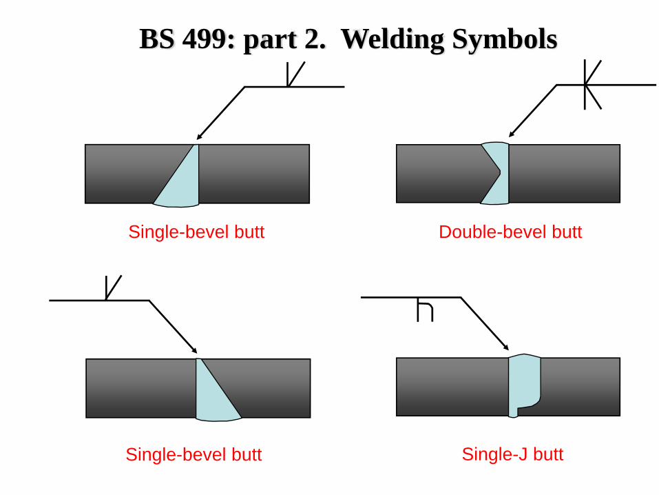
Single-bevel butt Double-bevel butt
Single-bevel butt Single-J butt
BS 499: part 2. Welding Symbols
BS 499: part 2. Welding Symbols
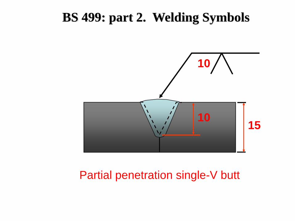
Partial penetration single-V butt
10
10 15
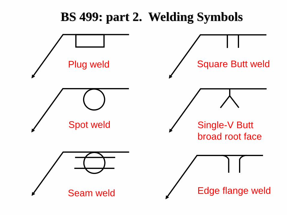
Plug weld
Spot weld
Seam weld
Square Butt weld
Single-V Butt broad root face
Edge flange weld
BS 499: part 2. Welding Symbols
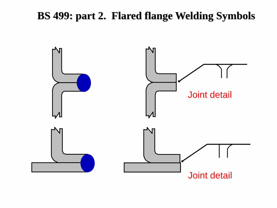
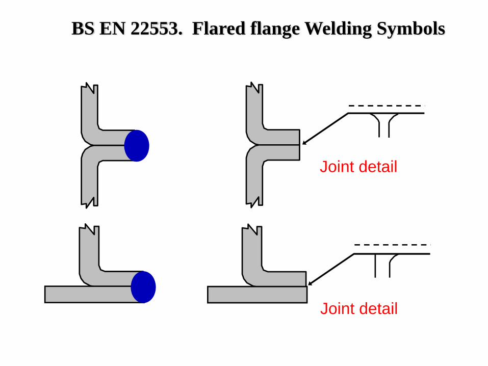
BS 499: part 2. Flared flange Welding Symbols
Joint detail
Joint detail
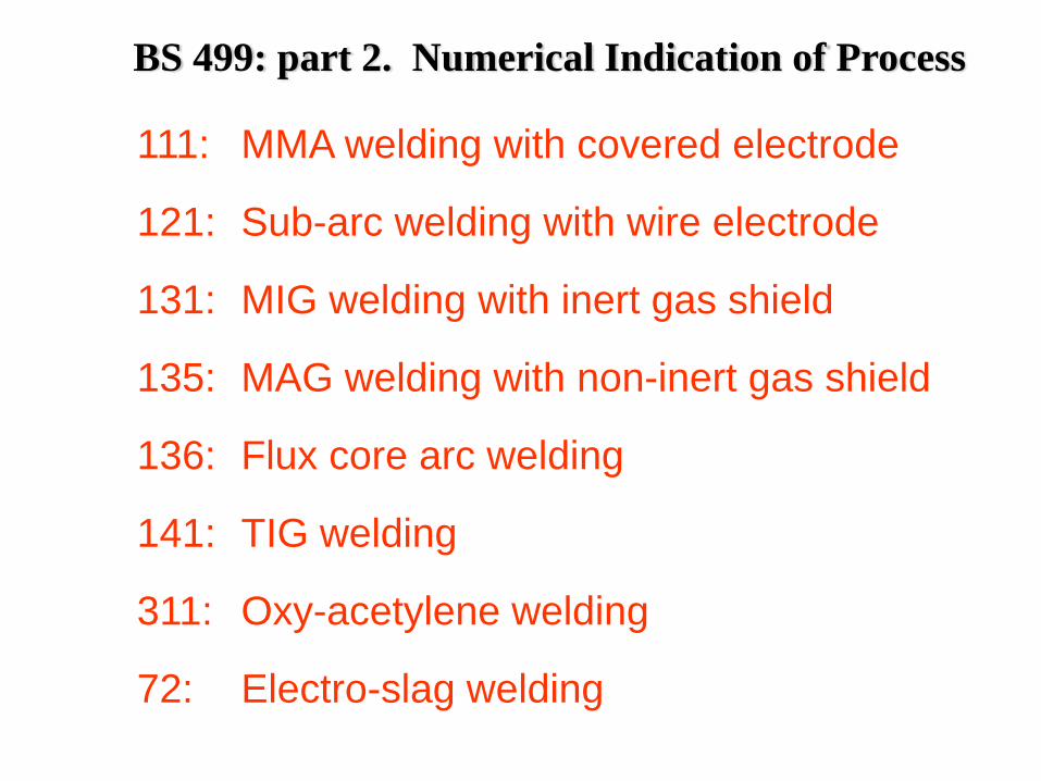
BS 499: part 2. Numerical Indication of Process
111: MMA welding with covered electrode
121: Sub-arc welding with wire electrode
131: MIG welding with inert gas shield
135: MAG welding with non-inert gas shield
136: Flux core arc welding
141: TIG welding
311: Oxy-acetylene welding
72: Electro-slag welding
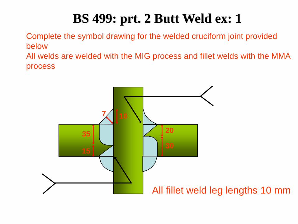
BS 499: prt. 2 Butt Weld ex: 1Complete the symbol drawing for the welded cruciform joint provided belowAll welds are welded with the MIG process and fillet welds with the MMA process
20
3035
15
107
All fillet weld leg lengths 10 mm
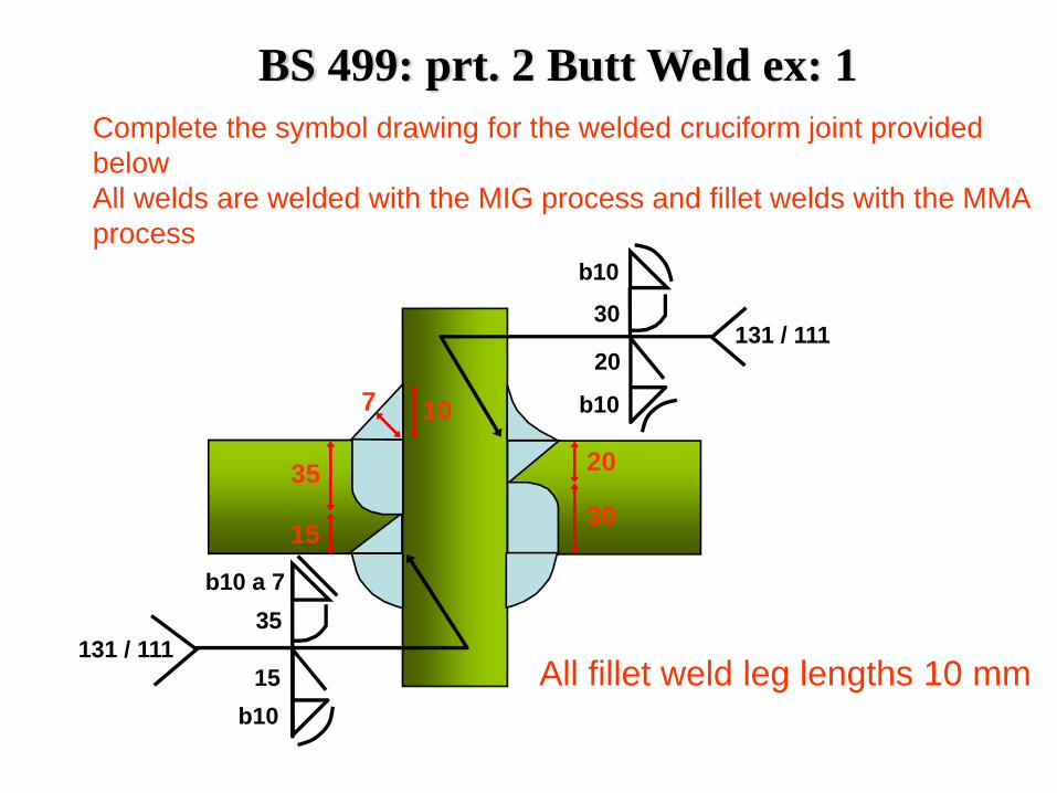
20
3035
15
107
Complete the symbol drawing for the welded cruciform joint provided belowAll welds are welded with the MIG process and fillet welds with the MMA process
All fillet weld leg lengths 10 mm
b10
30
20
b10
131 / 111
131 / 111
b10 a 7
b1015
35
BS 499: prt. 2 Butt Weld ex: 1
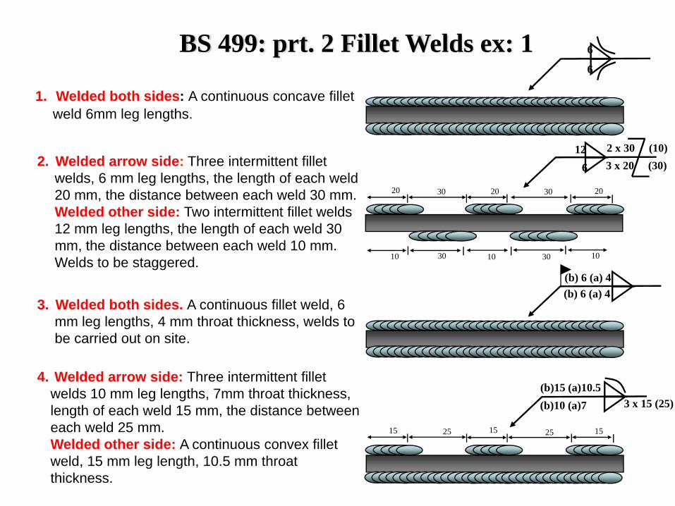
BS 499: prt. 2 Fillet Welds ex: 1
1. Welded both sides: A continuous concave fillet weld 6mm leg lengths.
2. Welded arrow side: Three intermittent fillet welds, 6 mm leg lengths, the length of each weld 20 mm, the distance between each weld 30 mm.Welded other side: Two intermittent fillet welds 12 mm leg lengths, the length of each weld 30 mm, the distance between each weld 10 mm. Welds to be staggered.
3. Welded both sides. A continuous fillet weld, 6 mm leg lengths, 4 mm throat thickness, welds to be carried out on site.
4. Welded arrow side: Three intermittent fillet welds 10 mm leg lengths, 7mm throat thickness, length of each weld 15 mm, the distance between each weld 25 mm.Welded other side: A continuous convex fillet weld, 15 mm leg length, 10.5 mm throat thickness.
6
6
2 x 30 (10)126 3 x 20 (30)
10 1030 10 30
20 202030 30
(b) 6 (a) 4(b) 6 (a) 4
15 1515 2525
(b)15 (a)10.5(b)10 (a)7 3 x 15 (25)
BS EN 22553 (ISO 2553) Welding Symbols
BS EN 22553 (ISO 2553) Welding Symbols
Arrow line
Reference lines
Arrow side
Other side Arrow side
Other side
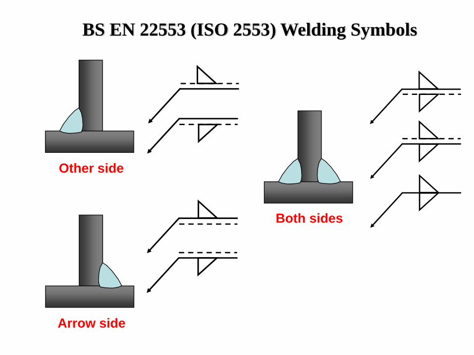
Other side
Arrow side
Both sides
BS EN 22553 (ISO 2553) Welding Symbols
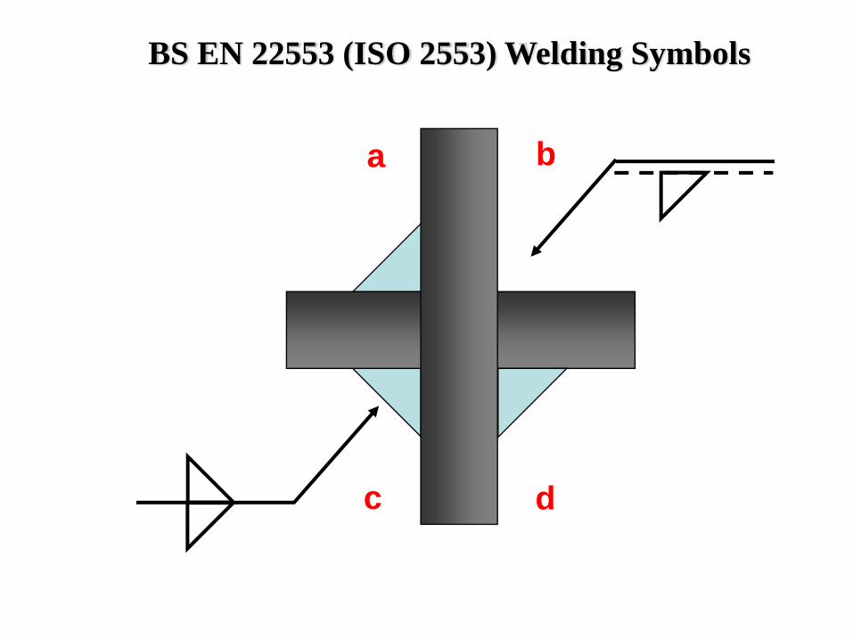
ba
dc
BS EN 22553 (ISO 2553) Welding Symbols
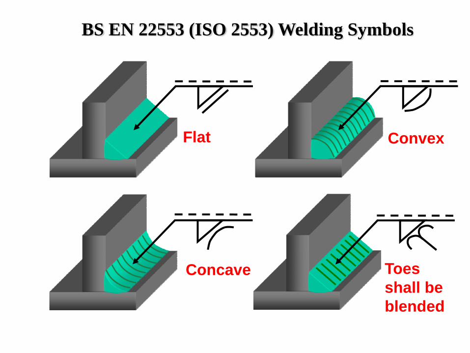
Convex
Concave
Flat
Toes shall be blended
BS EN 22553 (ISO 2553) Welding Symbols
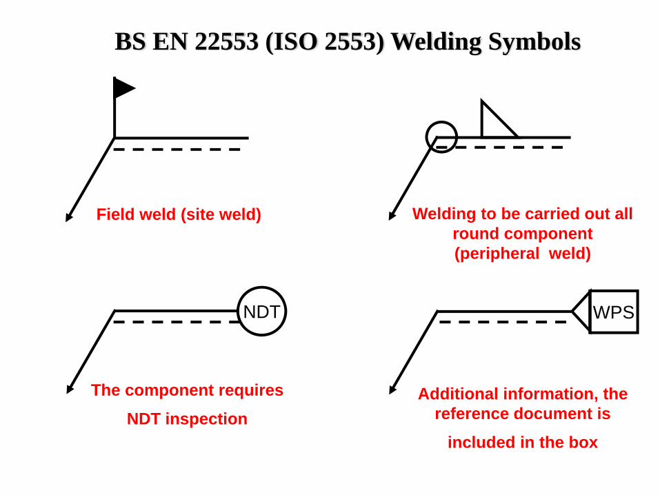
Field weld (site weld)
NDT
The component requires
NDT inspection
WPS
Additional information, the reference document is
included in the box
Welding to be carried out all round component (peripheral weld)
BS EN 22553 (ISO 2553) Welding Symbols
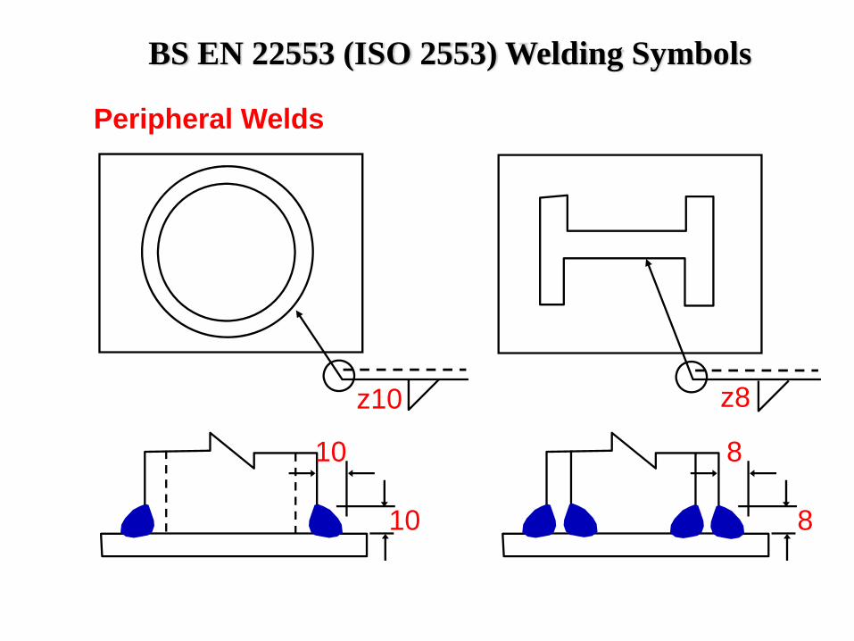
z10 z8
10
10
8
8
Peripheral Welds
BS EN 22553 (ISO 2553) Welding Symbols
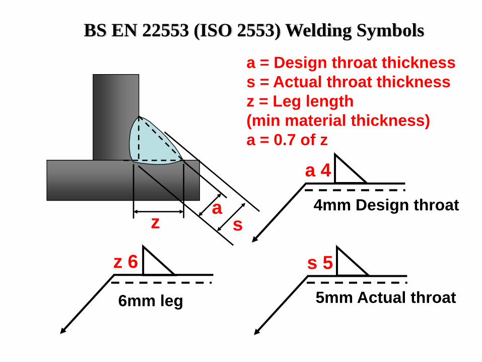
a = Design throat thicknesss = Actual throat thicknessz = Leg length(min material thickness)a = 0.7 of z
a 4
4mm Design throat
z 6
6mm leg
az s
s 5
5mm Actual throat
BS EN 22553 (ISO 2553) Welding Symbols
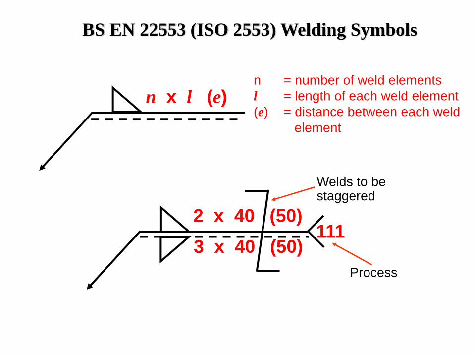
n = number of weld elementsl = length of each weld element(e) = distance between each weld
element
n x l (e)
Welds to be staggered
Process
2 x 40 (50)3 x 40 (50)
111
BS EN 22553 (ISO 2553) Welding Symbols
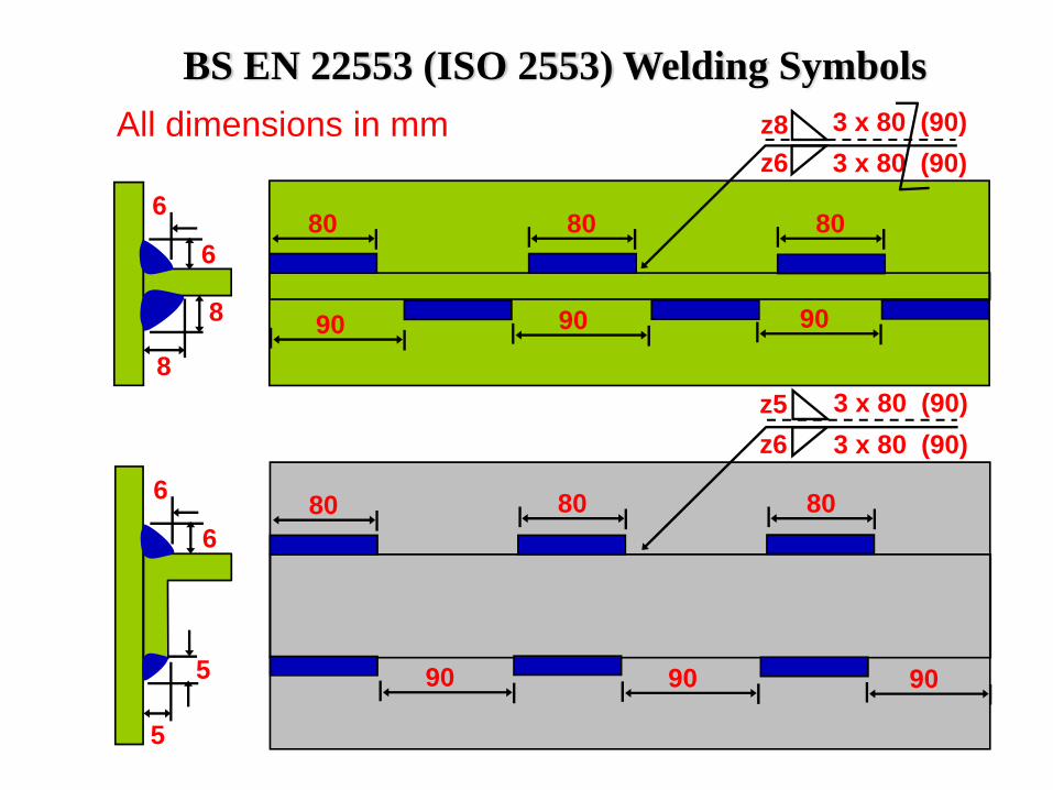
8
8
6
6
z8z6
3 x 80 (90)3 x 80 (90)
80 80 80
909090
z5z6
3 x 80 (90)3 x 80 (90)
80 80 80
909090
5
5
6
6
All dimensions in mmBS EN 22553 (ISO 2553) Welding Symbols
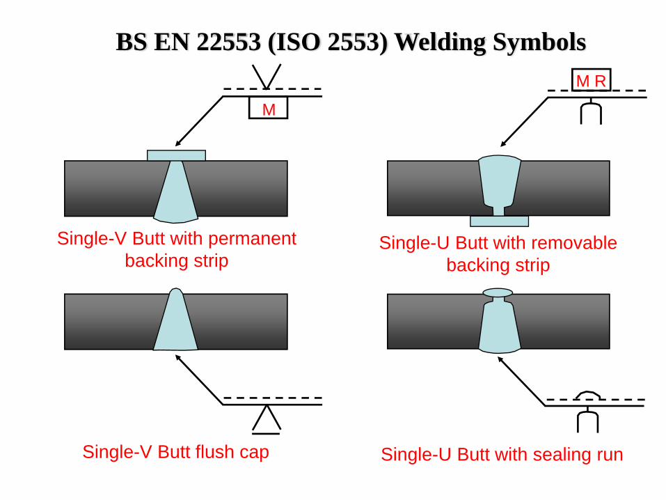
Single-V Butt flush cap Single-U Butt with sealing run
Single-V Butt with permanent backing strip
M
Single-U Butt with removable backing strip
M R
BS EN 22553 (ISO 2553) Welding Symbols
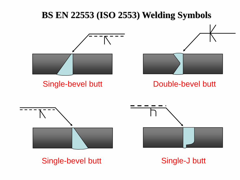
Single-bevel butt Double-bevel butt
Single-bevel butt Single-J butt
BS EN 22553 (ISO 2553) Welding Symbols
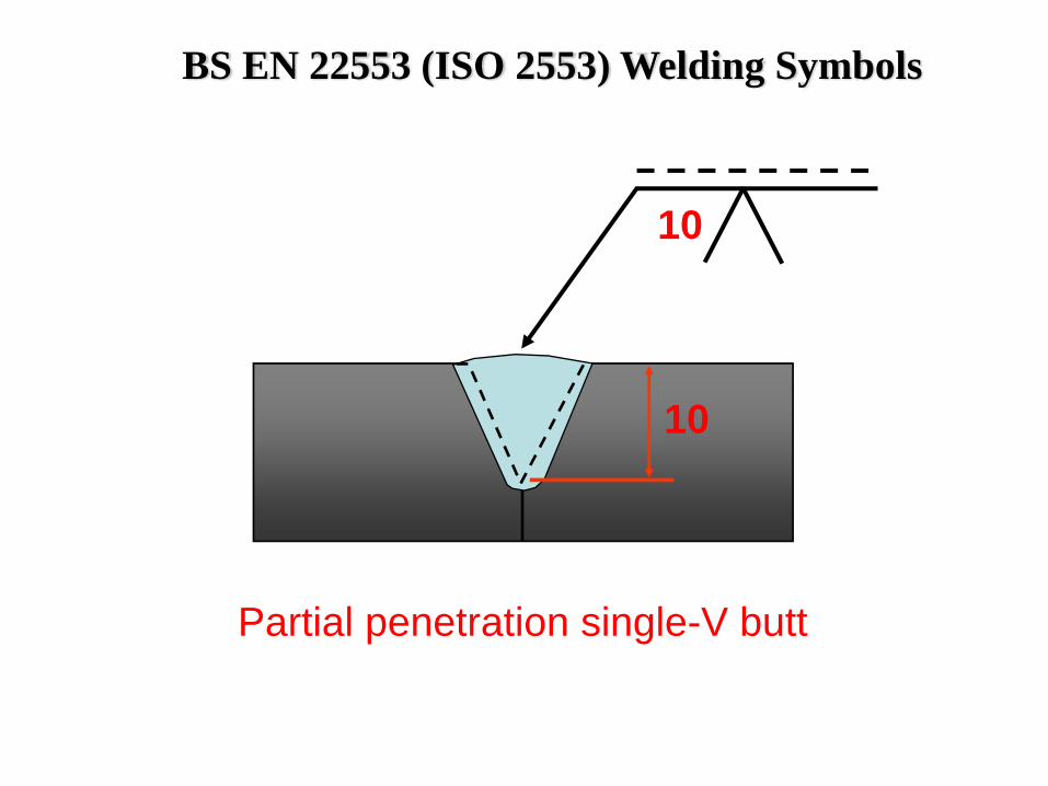
Partial penetration single-V butt
10
10
BS EN 22553 (ISO 2553) Welding Symbols
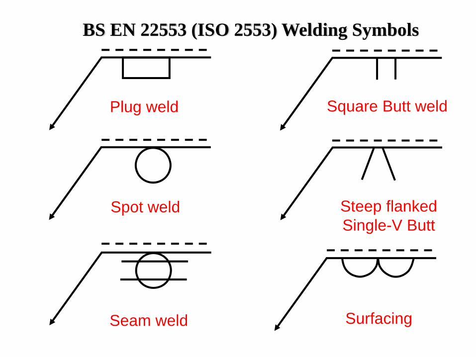
Plug weld
Spot weld
Seam weld
Square Butt weld
Steep flanked Single-V Butt
Surfacing
BS EN 22553 (ISO 2553) Welding Symbols
BS EN 22553. Flared flange Welding Symbols
Joint detail
Joint detail
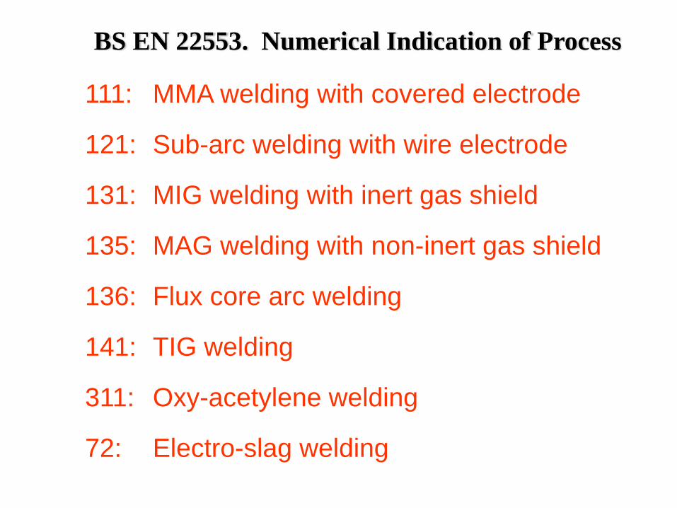
BS EN 22553. Numerical Indication of Process
111: MMA welding with covered electrode
121: Sub-arc welding with wire electrode
131: MIG welding with inert gas shield
135: MAG welding with non-inert gas shield
136: Flux core arc welding
141: TIG welding
311: Oxy-acetylene welding
72: Electro-slag welding
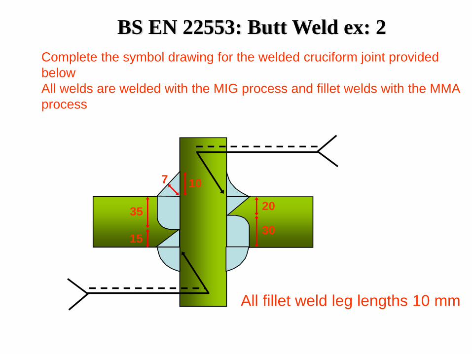
BS EN 22553: Butt Weld ex: 2
20
3035
15
107
Complete the symbol drawing for the welded cruciform joint provided belowAll welds are welded with the MIG process and fillet welds with the MMA process
All fillet weld leg lengths 10 mm
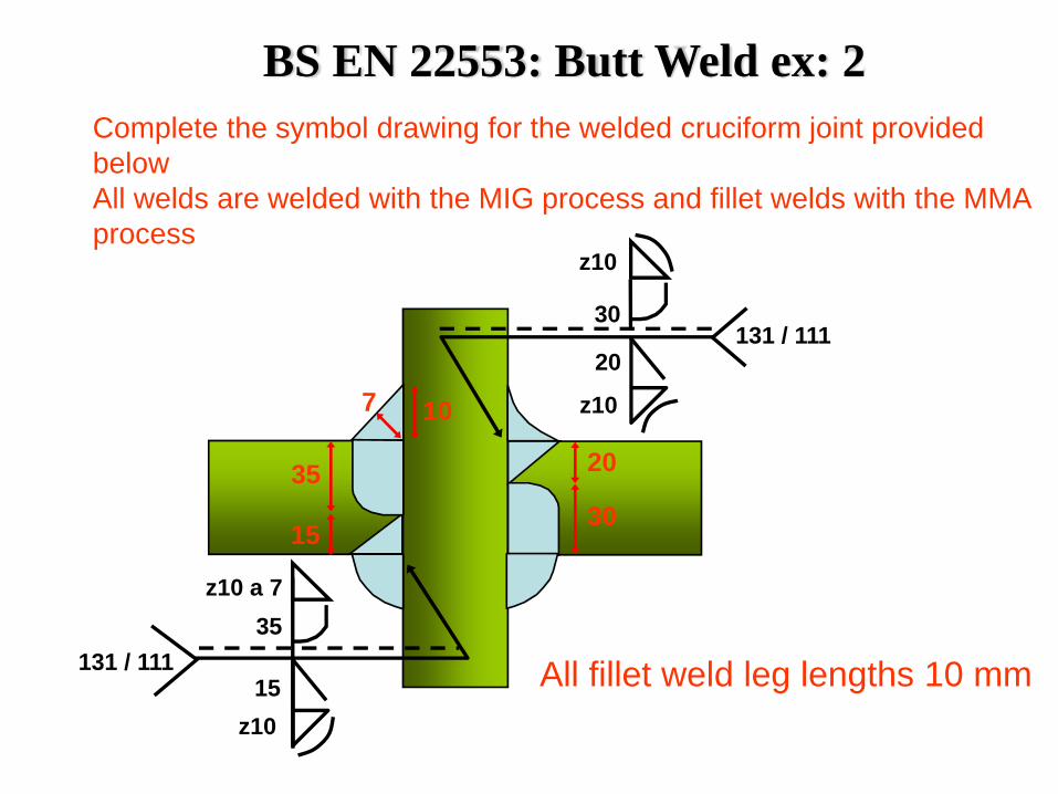
20
3035
15
107
Complete the symbol drawing for the welded cruciform joint provided belowAll welds are welded with the MIG process and fillet welds with the MMA process
All fillet weld leg lengths 10 mm
z10
30
20
z10
131 / 111
131 / 111
z10 a 7
z1015
35
BS EN 22553: Butt Weld ex: 2
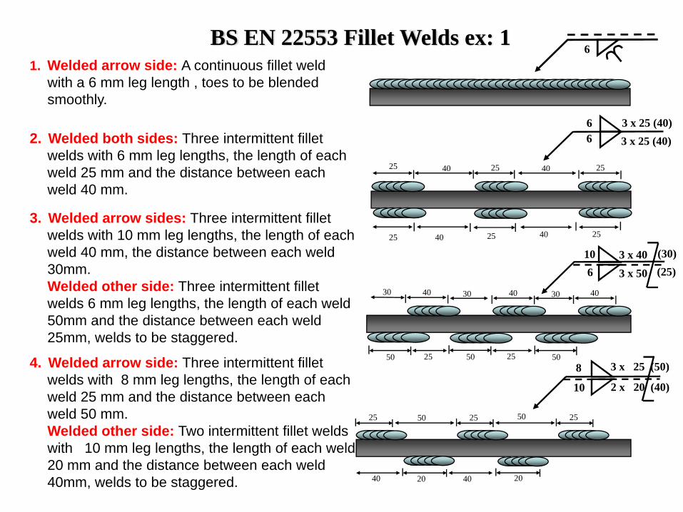
BS EN 22553 Fillet Welds ex: 11. Welded arrow side: A continuous fillet weld
with a 6 mm leg length , toes to be blended smoothly.
2. Welded both sides: Three intermittent fillet welds with 6 mm leg lengths, the length of each weld 25 mm and the distance between each weld 40 mm.
3. Welded arrow sides: Three intermittent fillet welds with 10 mm leg lengths, the length of each weld 40 mm, the distance between each weld 30mm.Welded other side: Three intermittent fillet welds 6 mm leg lengths, the length of each weld 50mm and the distance between each weld 25mm, welds to be staggered.
4. Welded arrow side: Three intermittent fillet welds with 8 mm leg lengths, the length of each weld 25 mm and the distance between each weld 50 mm.Welded other side: Two intermittent fillet welds with 10 mm leg lengths, the length of each weld 20 mm and the distance between each weld 40mm, welds to be staggered.
6
3 x 25 (40)3 x 25 (40)
25 40 25
66
40 25
25 2525 4040
40
50
40
5050 25 25
30 30 4030
106
3 x 403 x 50 (25)
(30)
505025 25
40 4020 20
25
3 x 25 (50)
2 x 20 (40)10
8
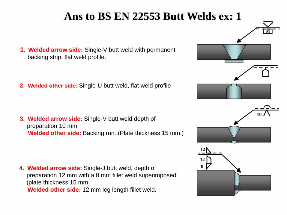
Ans to BS EN 22553 Butt Welds ex: 1
1. Welded arrow side: Single-V butt weld with permanent backing strip, flat weld profile.
M
2. Welded other side: Single-U butt weld, flat weld profile
3. Welded arrow side: Single-V butt weld depth of preparation 10 mmWelded other side: Backing run. (Plate thickness 15 mm.)
4. Welded arrow side: Single-J butt weld, depth of preparation 12 mm with a 8 mm fillet weld superimposed. (plate thickness 15 mm.Welded other side: 12 mm leg length fillet weld.
10
12
128
AWS Welding Symbols
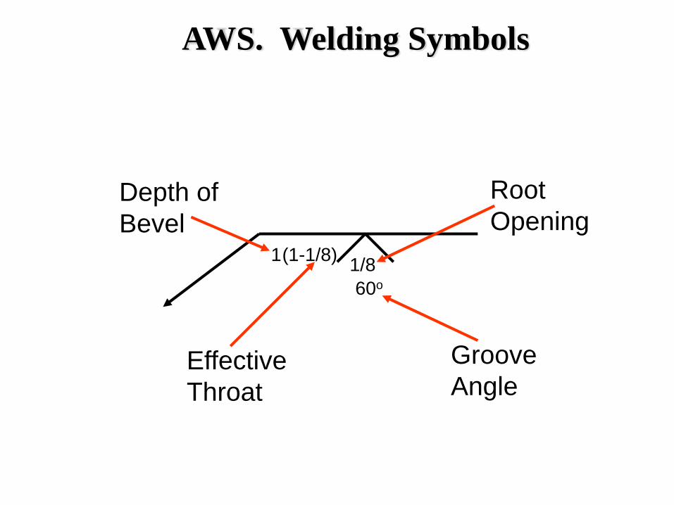
1(1-1/8)
60o1/8
Depth of Bevel
Effective Throat
Root Opening
Groove Angle
AWS. Welding Symbols
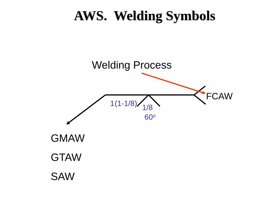
1(1-1/8)
60o1/8
FCAW
Welding Process
GMAW
GTAW
SAW
AWS. Welding Symbols
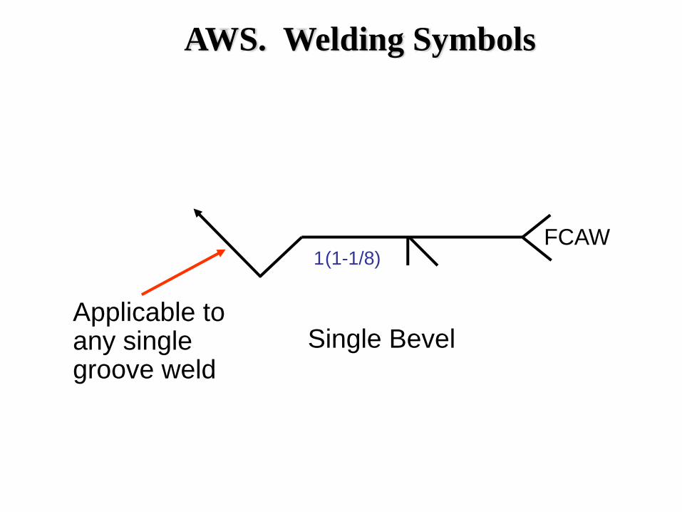
1(1-1/8)FCAW
Single BevelApplicable to any single groove weld
AWS. Welding Symbols
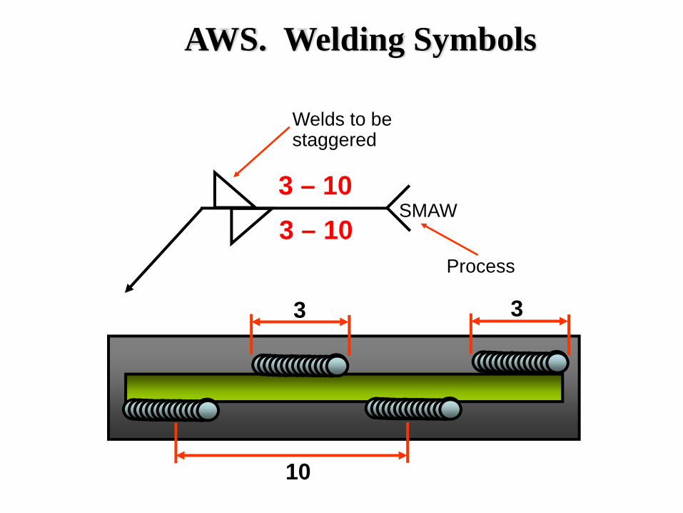
3 – 103 – 10
Welds to be staggered
SMAW
Process
10
3 3
AWS. Welding Symbols
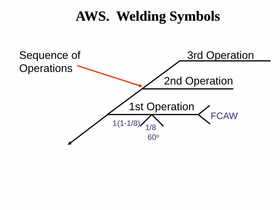
1(1-1/8)
60o1/8
FCAW
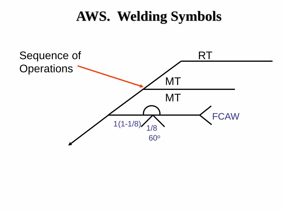
Sequence of Operations
1st Operation
2nd Operation
3rd Operation
AWS. Welding Symbols
1(1-1/8)
60o1/8
FCAW
Sequence of Operations
RT
MTMT
AWS. Welding Symbols
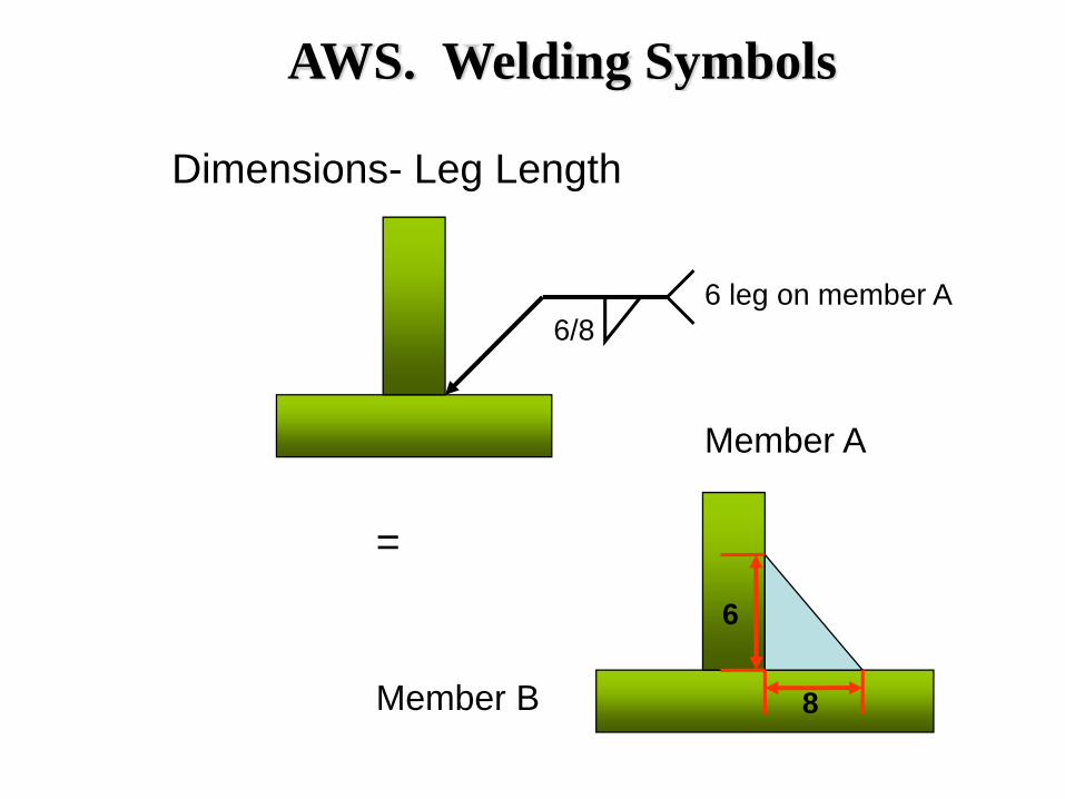
Dimensions- Leg Length
6/86 leg on member A
=
8
6
Member A
Member B
AWS. Welding Symbols