welding design overview
DESCRIPTION
Application and interpretation of welding requirementsTRANSCRIPT

Welding Design Overview
Module 1C

Module 1 – Introduction Welding Design Overview
Welding Design and Testing
Understand the basic principals pertaining to weld design with emphasis on the following
The basic types of weld jointsThe basic types of welds and their symbolsResidual stress and weld distortionMechanical property testing
1-2
Fitness-for-service

Module 1 – Introduction Welding Design Overview
Importance of Weld Design
Proper weld design and testing ensures that welds do not fail under their intended load and environmental conditions
The proper base materials must be chosen (and filler metals when applicable)Appropriate weld strength requirements must be metWeld toughness and ductilitytargets must be established
1-3
targets must be establishedFatigue resistance against cyclic loading has to be considered
Liberty Ship Failure - 1943

Module 1 – Introduction Welding Design Overview
Basics of Joint Design
The shape, dimensions, and configuration of the joint(s) are specified by the applicable welding code and designerFive basic joint types
Butt (1)Corner (2)Lap (3) 1
1-4
Tee (4)Edge (5)
Several variations of each type
4
3
5
1
Flange Edge Joints
2

Module 1 – Introduction Welding Design Overview
Joint Design Variables
1
1. Bevel angle
1-5
3. Root face (land)
3
2
2. Root opening(root gap)

Module 1 – Introduction Welding Design Overview
Welding Symbol Example
Basic example of a welding symbol for fillet weld
1-6
FCAW125/16

Module 1 – Introduction Welding Design Overview
Weld Nomenclature
1. Weld face
1
2
2 W ld t
1-7
1
3
2. Weld toes
3. Leg length
4. Depth-of-fusion4
5
5. Actual throat

Module 1 – Introduction Welding Design Overview
Residual Stress Concept
Residual stress is the result of structural and metallurgical changes that take place during the welding process
Rapid localized heating (melting) and cooling (solidifying) Stresses can be high enoughto surpass the yield strength of the base metal
1-8
of the base metal
Two major effects:Distortion Premature failure

Module 1 – Introduction Welding Design Overview
Types of Weld Distortion
(a) Transverse Shrinkage
(b) A l Ch
(d) Longitudinal Shrinkage
( ) L it di l B di
1-9
(b) Angular Change
(c) Rotation Distortion (f) Buckling Distortion
(e) Longitudinal Bending
Reference: Welding Handbook, Volume 1, AWS, 1991

Module 1 – Introduction Welding Design Overview
What is the Significance?
Residual stress:Degraded structural performanceReduced service life
CompressionBuckling can occur at lower than expected loads
Tension
1-10
TensionCan lead to higher than expected local stresses, resulting in cracking
Tension
CompressionY
Y
X

Module 1 – Introduction Welding Design Overview
Controlling Stress and Distortion
Several methods exist for better control of residual stress and distortion
Reduce the total volume of weld metal through joint design improvementsPre-set the joint prior to welding
1-11
Pre-set the joint prior to weldingPreheat the joint
Post-weld flame heating can be used to remove distortion

Module 1 – Introduction Welding Design Overview
Weld Properties
From a weld design standpoint, it is important to understand the mechanical properties of weldsSome of the important properties of a weld include:
Strength – the ability to withstand an applied loadDuctility – the ability to deform/stretch without failingHardness – the ability to resist indentation
1-12
Toughness – the ability to absorb energySoundness – freedom from imperfectionsFatigue strength – resistance to failure under repeated loads

Module 1 – Introduction Welding Design Overview
There are numerous tests used to determine the various properties of welds
Non destructive tests (does not hinder future usage)Destructive tests (render the part useless)
Module 4 will cover the following destructive test methods used to evaluate properties
Tension tests – mechanical properties
Testing Weld Properties
1-13
Tension tests mechanical propertiesHardness tests – mechanical propertiesFracture toughness tests – mechanical propertiesBend tests – weld soundness

Module 1 – Introduction Welding Design Overview
Several standards and guidelines exist for tensile testingASTM E8 “Standard Methods of Tension Testing of Metallic Materials”
SignificanceTension tests provide informationon many different properties
StrengthD tilit
Tension Tests
1-14
DuctilityToughnessCan test the entire weld joint or just the weld metal
All Weld Metal Tensile Test
Gauge Length
Module 1 – Introduction Welding Design Overview
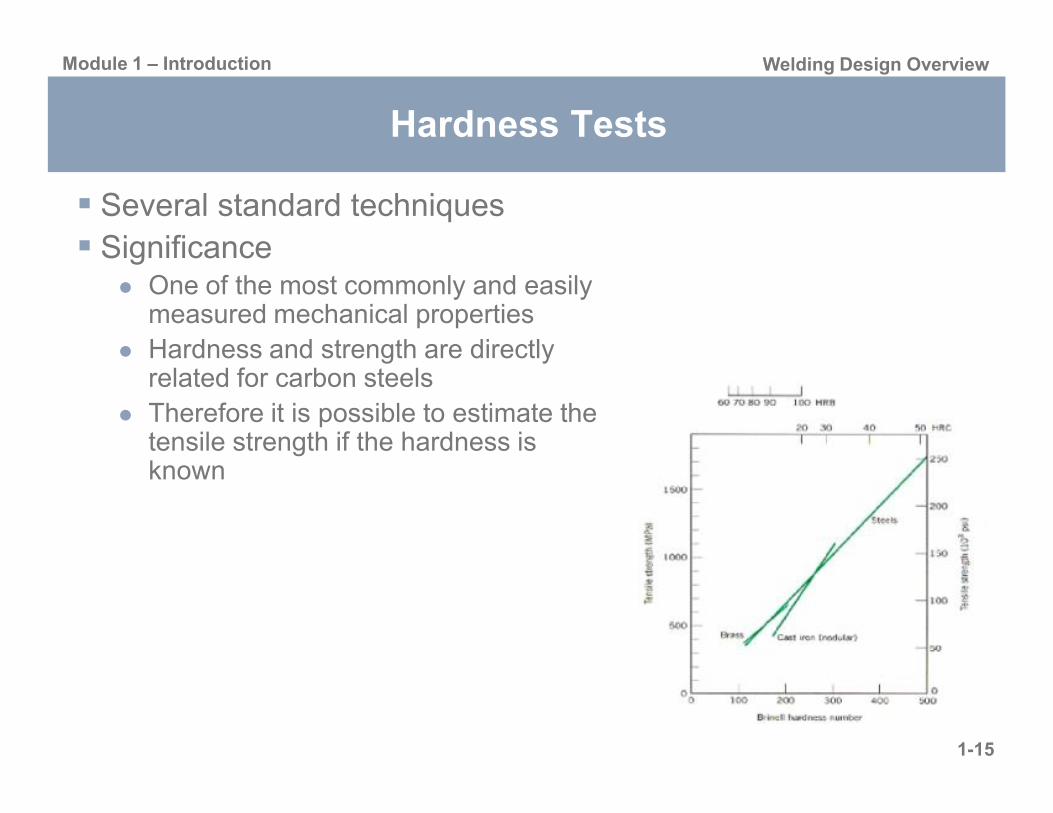
Hardness Tests
Several standard techniquesSignificance
One of the most commonly and easily measured mechanical propertiesHardness and strength are directly related for carbon steelsTh f it i ibl t ti t th
1-15
Therefore it is possible to estimate the tensile strength if the hardness is known
Module 1 – Introduction Welding Design Overview
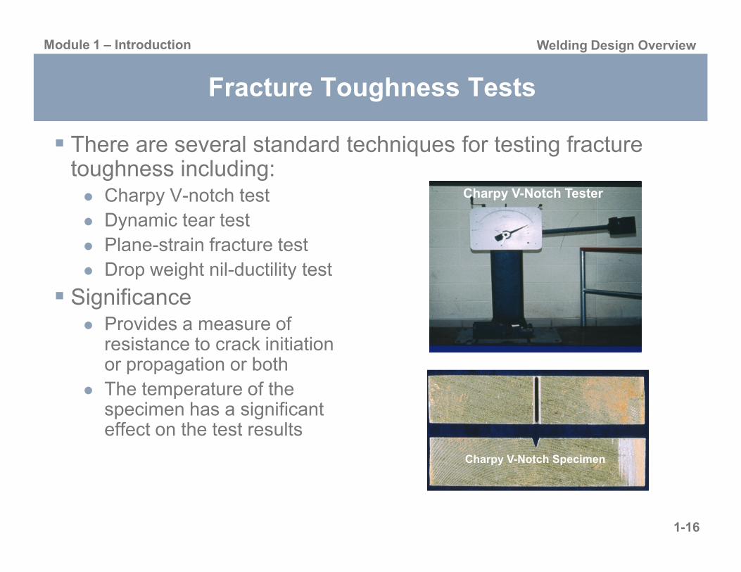
Fracture Toughness Tests
There are several standard techniques for testing fracture toughness including:
Charpy V-notch testDynamic tear testPlane-strain fracture testDrop weight nil-ductility test
Charpy V-Notch Tester
1-16
SignificanceProvides a measure of resistance to crack initiation or propagation or bothThe temperature of the specimen has a significant effect on the test results
Charpy V-Notch Specimen

Module 1 – Introduction Welding Design Overview
Bend Tests
There are three standard techniques for bend testingGuided bendRoller equippedguided bendWrap-aroundguided bend
Significance Side Bend Root Bend
1-17
SignificanceTo assess weld soundness in procedure and performance qualificationsThe ductility of a weld Side Bend Face Bend

Weldability Overview
Module 1D
Module 1 – Introduction Weldability Overview
Weld Defects
Fabrication-relatedAssociated with primary fabrication or repairCan be controlled by combination of metallurgical and welding process factorsUse of appropriate inspection techniques is critical
Service-related
1-19
Occur upon exposure to service environmentGenerally mechanically or environmentally inducedMay result from remnant weld defects or metallurgical phenomena associated with the weld thermal cycleInspection and design issues are important to control defect formation and monitor propagation

Module 1 – Introduction Weldability Overview
Non-Metallurgical Fabrication Defects
Lack of Fusion (SMAW) Oxidation
Undercut Intrusion
1-20
Drop-ThroughOverbead Porosity

Module 1 – Introduction Weldability Overview
Cracking Phenomena
Solidification Cracking – “Hot Cracking”HAZ/PMZ liquation crackingWeld metal liquation cracking
Solid-State Cracking – “Warm Cracking”Ductility dip crackingReheat cracking
1-21
Strain-age crackingCopper contamination cracking
Hydrogen-Induced Cracking - “Cold Cracking”

Module 1 – Introduction Weldability Overview
Solidification Cracking
1-22

Module 1 – Introduction Weldability Overview
Solid-State Cracking
1-23
Ductility Dip Cracking Reheat Cracking

Module 1 – Introduction Weldability Overview
Hydrogen Induced Cracking
1-24

Module 1 – Introduction Weldability Overview
Fatigue and Fractures
Ran
ge Good fatigue
resistancePoor fatigueresistance
1-25
Str
es
Number of Cycles
Fatiguelimit
Module 1 – Introduction Weldability Overview
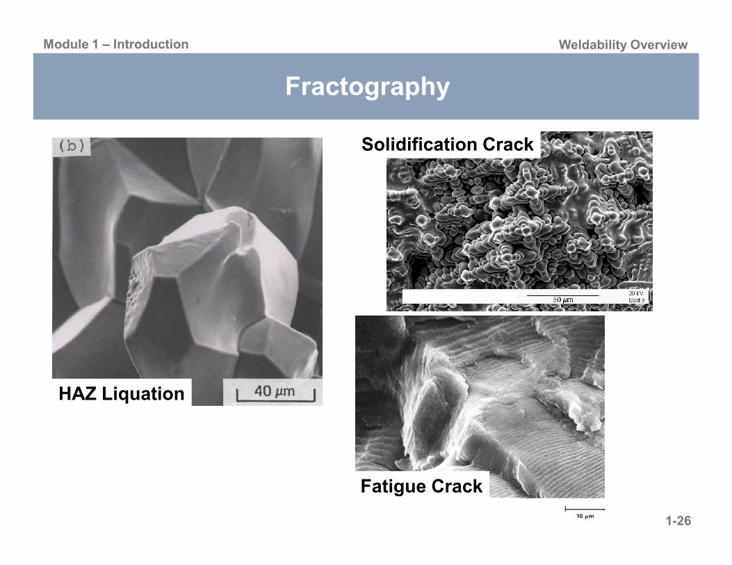
Fractography
Solidification Crack
1-26
Fatigue Crack
HAZ Liquation

Module 1 – Introduction Weldability Overview
Corrosion
Surface
Pit
1-27
SubsurfaceAttack
Sensitization of Stainless Steels
Pitting Corrosion

Inspection Overview
Module 1E

Module 1 – Introduction Inspection Overview
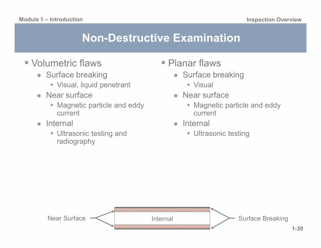
Non-Destructive Examination
1-29
Module 1 – Introduction Inspection Overview
Planar flawsSurface breaking
Visual
Near surfaceMagnetic particle and eddy current
Internal
Volumetric flawsSurface breaking
Visual, liquid penetrant
Near surface Magnetic particle and eddy current
Internal
Non-Destructive Examination
1-30
Internal Ultrasonic testing
Internal Ultrasonic testing and radiography
Surface BreakingInternalNear Surface

Module 1 – Introduction Inspection Overview
Non-Destructive Examination
Volumetric flawsPorosityInclusions
SlagTungsten
ShrinkageH l d id
Planar flawsSeamsLaminationLack of bondingForging/rolling lapFatigue cracks
1-31
Holes and voidsCorrosion
Thinning/lossPitting
Stress corrosion cracksIncomplete fusionIncomplete penetration

Module 1 – Introduction Inspection Overview
Visual Testing (VT)
RulersTape measuresCalipersBorescopesRemote crawlers with cameras
1-32
Dimensional conformance, flaw detection
Module 1 – Introduction Inspection Overview
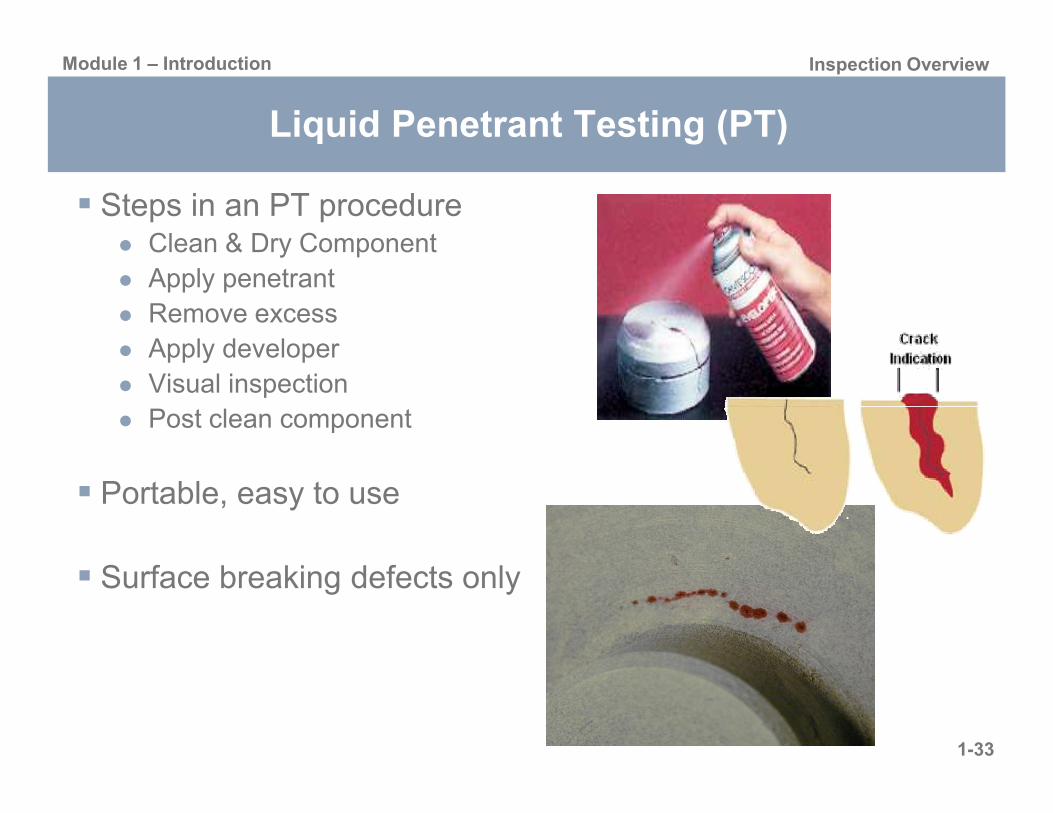
Liquid Penetrant Testing (PT)
Steps in an PT procedureClean & Dry ComponentApply penetrantRemove excessApply developerVisual inspection
1-33
Post clean component
Portable, easy to use
Surface breaking defects only
Module 1 – Introduction Inspection Overview
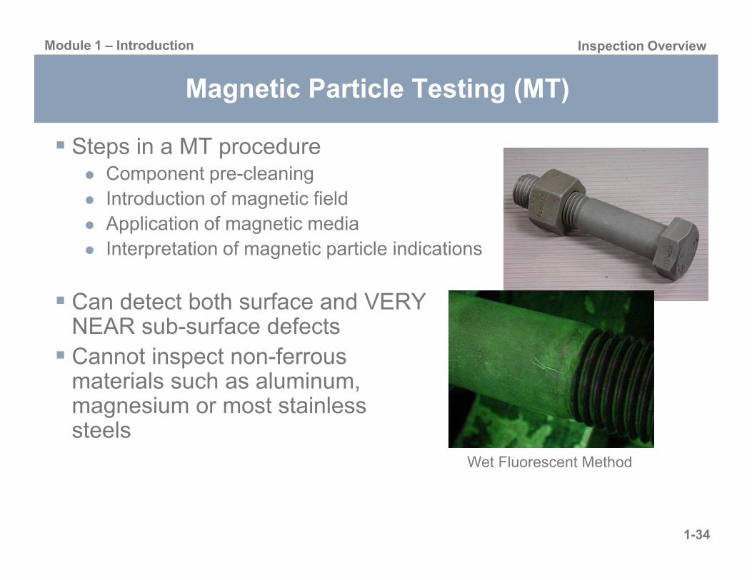
Magnetic Particle Testing (MT)
Steps in a MT procedureComponent pre-cleaningIntroduction of magnetic fieldApplication of magnetic mediaInterpretation of magnetic particle indications
1-34
Can detect both surface and VERY NEAR sub-surface defectsCannot inspect non-ferrous materials such as aluminum, magnesium or most stainless steels
Wet Fluorescent Method

Module 1 – Introduction Inspection Overview
Eddy Current Testing (ECT)
Uses the principal of “electromagnetism” as the basis for conducting examinations
Surface and slightly subsurface detection capabilities
1-35
pDiscontinuities
Cracks, pores
GeometryScratches, undercut
Material propertiesHeat treatment, residual stresses, hardness, phase composition, creep, fatigue, corrosion

Module 1 – Introduction Inspection Overview
Radiographic Testing (RT)
The part is placed between the radiation source and a piece of film
Part absorbs some radiationThicker and more dense area will stop more of the radiationSafety precautions
1-36
Safety precautions
Technique is not limited by material type or density
Detects both surface and subsurface defects
Orientation of equipmentand flaw can be critical
Extensive training
= more exposure
= less exposure
Top view of developed film
X-ray film

Module 1 – Introduction Inspection Overview
Ultrasonic Testing (UT)
Sound produced by a vibrating body (transducer) and travels in the form of a wave
Similar to light waves, they can be reflected, refracted, and focusedUltrasonic reflections from the presence of discontinuities or
1-37
presence of discontinuities or geometric features enables detectionand location
plate
crack
0 2 4 6 8 10
initial pulse
crackecho
back surfaceecho
UT Instrument Screen
Module 1 – Introduction Inspection Overview
Summary
Introduce common non-destructive inspection techniques, procedures, and equipment Describe advantages and limitationsDemonstrate how to select the best process for a given application
1-38

Module 1 – Introduction Inspection Overview
Fitness-for-Service Concept
DefinitionQuantitative engineering evaluations demonstrating the structural integrity of a flawed or damaged component and their fitness for intended purpose
RationaleDesign/welding codes and standards do not address the fact that structures degrade while in service
1-39
structures degrade while in service
Benefits Make run/repair/replace decisionsReduce unnecessary repairs and avoid unplanned shutdownsAccurately predict structural behaviors in service

Module 1 – Introduction Inspection Overview
What Does FFS Cover?
Safe operationPresent the integrity of the component given current state of damage, operating loads, and environmental conditions
Safety margin and re-ratingThe limiting operating condition to avoid failure of equipment containing a known or postulated flaw
P j t d i i lif
1-40
Projected remaining lifeRun, repair, or replace based on future operation conditions and environmental compatibility

Welding Codes Overview
Module 1F

Module 1 – Introduction Welding Codes Overview
Products Covered by Standards of Various Organizations
Product AISC ASME ASTM AWS
Base Metals X X X
Bridges X X
Buildings X X
Construction equip. X
Filler metals X X
1-42
Machine tools X
Power gen. equip. X
Piping X X
Presses X
Pressure vessels, boilers X
Ships X
Storage tanks X
Structures, general X X

Module 1 – Introduction Welding Codes Overview
American National Standards Institute (ANSI)
Coordinating organization for US voluntary standards systemDoes not produce standards, but approves those produced by other organizationsUS member of ISO and International Electrotechnical Commission (IEC)Approximately 10 000 ANSI documents currently
1-43
Approximately 10,000 ANSI documents currentlyProvide a common language that can be used confidently by industry, suppliers, customers, business, the public, government, and labor

Module 1 – Introduction Welding Codes Overview
American Society for Testing and Materials (ASTM)
Develops and publishes specifications for use in the production and testing of materials
ASTM E8 – Tensile Testing of Metallic Materials
Cover virtually all materials used in industry and commerce with exception of welding consumables, which are covered by AWS
1-44
Currently publish 15 sections comprising 65 volumes and an indexWhen ASTM specifications adopted by ASME for certain applications, either in its entirety or in a revised form, ASME adds an “S” in front of ASTM letter prefix
ASTM A105, Carbon steel forgings for piping applications, is listed as SA-105 in ASME
Module 1 – Introduction Welding Codes Overview
National Board of Boiler and Pressure Vessel Inspectors (NBBPVI)
Often referred to as the National Board, represents the enforcement agencies empowered to assure adherence to ASME B&PVCInvolved in boiler and pressure vessel registration and investigation of possible Code violations
1-45
Publishes National Board Inspection Code (NBIC) that describes maintenance, inspection and repair requirementsBoiler and pressure vessel repair, governed by the “R” stamp is also under their jurisdiction
Module 1 – Introduction Welding Codes Overview
American Welding Society (AWS)
Publishes numerous documents covering welding and welding related activitiesAWS produces codes, specifications, recommended practices, classifications, methods, and guides related to weldingGeneral subject areas
1-46
jDefinitions and symbols, filler metals, qualification and testing, welding processes, welding applications, safety

Module 1 – Introduction Welding Codes Overview
Overview of AWS D1.1 – Structural Welding Code
General RequirementsDesign of Welded ConnectionsPrequalification of WPSsQualificationFabricationI ti
1-47
InspectionStud WeldingStrengthening & Repairing Existing StructuresAnnexes (Mandatory): A – JAnnexes (Informative): K – VCommentaryIndex
Module 1 – Introduction Welding Codes Overview
Overview of AWS D1.1 – Structural Welding Code
Chapter 1, General RequirementsBasic information on the scope and limitations of the codeLimitations - NOT intended to be used for the following
Yield stress > 100-ksi (690-Mpa)Thickness < 1/8-in (3.2-mm)Pressure vessels, pressure piping, bridgesBase metal other than carbon or low alloy steels
1-48
Base metal other than carbon or low-alloy steels
Definitions conform to AWS A3.0, supplemented by Annex KWelding symbols conform to AWS A2.4Engineer’s, contractor’s and inspector’s responsibilitiesSafety references, standard units of measurement and references

Module 1 – Introduction Welding Codes Overview
Overview of AWS D1.1 – Structural Welding Code
Chapter 2, Design of Welded ConnectionsRequirements for the design of welded connections composed of tubular, or nontubular, product form members
Part A – Common Requirements for Design of Welded Connections (Nontubular and Tubular Members)Part B – Specific Requirements for Design of Nontubular Connections (Statically or Cyclically Loaded)
1-49
Part C – Specific Requirements for Design of Nontubular Connections (Cyclically Loaded)Part D – Specific Requirements for Design of Tubular Connections (Statically or Cyclically Loaded)

Module 1 – Introduction Welding Codes Overview
Overview of AWS D1.1 – Structural Welding Code
Chapter 3, Prequalification of WPSsPrequalified WPSs (SWPSs), such as those found in AWS B2.1, may be used without qualification
Limitations applyWelder performance still needs to be qualified in accordance with Section 4
Welding Processes
1-50
gPrequalified processes
SMAW, SAW, FCAW, and GMAW (except GMAW-S)FCAW and GMAW must use CV power supplies
Code approved processesESW, EGW, GMAW-S, and GTAWWPSs must be qualified in accordance with Section 4
Module 1 – Introduction Welding Codes Overview
Overview of AWS D1.1 – Structural Welding Code
Chapter 4, Qualification Requirements for qualification testing of WPSs and welding personnel
Part A – General RequirementsPart B – Welding Procedure Specification
Multiple positions, material shapes, and weld types can be qualified by a single WPS or welder performance qualification testChanges beyond the limitations of the PQR essential variables warrant
lifi ti
1-51
requalification
Part C – Performance QualificationPart D – Requirements for CVN Testing

Module 1 – Introduction Welding Codes Overview
Overview of AWS D1.1 – Structural Welding Code
Chapter 5, Fabrication Requirements for fabrication and erection of welded assemblies and structures produced by any process acceptable under AWS D1.1Contains 31 sections which cover numerous topics
Base metalWelding consumablesPreheat & interpass temperature
1-52
Preheat & interpass temperatureBacking, backing gas, or insertsPreparation of base metalTack welds & construction aidsControl of distortion & shrinkageRepairsMinimum fillet weld sizeEtc.

Module 1 – Introduction Welding Codes Overview
Overview of AWS D1.1 – Structural Welding Code
Chapter 6, Inspection Contains all of the requirements for the Inspector’s qualifications and responsibilities, acceptance criteria for discontinuities, and procedures for NDT
Part A – General RequirementsPart B – Contractor ResponsibilitiesPart C – Acceptance Criteria
1-53
pPart D – NDT ProceduresPart E – Radiographic Testing (RT)Part F – Ultrasonic Testing (UT) of Groove WeldsPart G – Other Examination Methods

Module 1 – Introduction Welding Codes Overview
American Society of Mechanical Engineers (ASME)
Two standing ASME committees actively involved in the formulation, revision, and interpretation of standards covering products that may be fabricated by weldingDocuments
ASME Boiler and Pressure Vessel CodeProvide minimum requirements for the design, materials, fabrication,
ti t ti d i ti f b il d l
1-54
erection, testing, and inspection of boilers and pressure vesselsTwelve (12) sections
Code for Pressure PipingProvide minimum requirements for the design, materials, fabrication, erection, testing, and inspection of piping systemsTwelve (12) sections
Module 1 – Introduction Welding Codes Overview
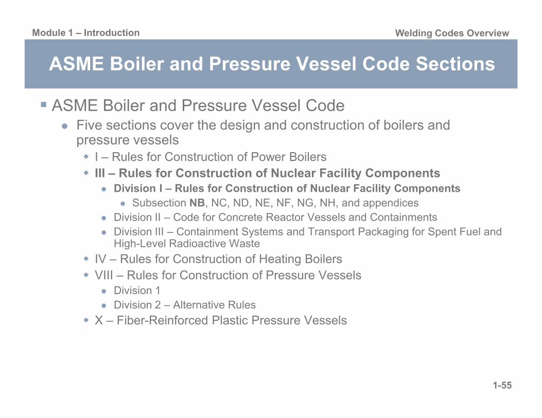
ASME Boiler and Pressure Vessel Code Sections
ASME Boiler and Pressure Vessel CodeFive sections cover the design and construction of boilers and pressure vessels
I – Rules for Construction of Power BoilersIII – Rules for Construction of Nuclear Facility Components
Division I – Rules for Construction of Nuclear Facility ComponentsSubsection NB, NC, ND, NE, NF, NG, NH, and appendices
1-55
Division II – Code for Concrete Reactor Vessels and ContainmentsDivision III – Containment Systems and Transport Packaging for Spent Fuel and High-Level Radioactive Waste
IV – Rules for Construction of Heating BoilersVIII – Rules for Construction of Pressure Vessels
Division 1Division 2 – Alternative Rules
X – Fiber-Reinforced Plastic Pressure Vessels

Module 1 – Introduction Welding Codes Overview
ASME Boiler and Pressure Vessel Code Sections
ASME Boiler and Pressure Vessel CodeSections cover material specifications, nondestructive examination, and welding and brazing qualifications
II – Materials Part A: Ferrous Material SpecificationsPart B: Nonferrous Material SpecificationsPart C: Specifications for Welding Rods, Electrodes, and Filler Materials
1-56
Part D: Properties
V – Nondestructive ExaminationIX – Welding and Brazing Qualifications
Part QW: WeldingPart QB: Brazing

Module 1 – Introduction Welding Codes Overview
ASME Boiler and Pressure Vessel Code Sections
ASME Boiler and Pressure Vessel CodeThree sections cover the care and operation of boilers or nuclear power plant components
VI – Recommended Rules for the Care and Operation of Heating BoilersVII – Recommended Guidelines for the Care of Power BoilersXI – Rules for In-service Inspection of Nuclear Power Plant Components
1-57
One section covers the construction and continued service of transport tanks
XII – Rules for Construction and Continued Service of Transport Tanks

Module 1 – Introduction Welding Codes Overview
ASME B31 Code for Pressure Piping Sections
Provides minimum requirements for different piping systemsB31.1 – Power Piping B31.2 – Fuel Gas Piping B31.3 – Process PipingB31.4 – Pipeline Transportation Systems for Liquid Hydrocarbons and Other Liquids B31 5 R f i ti Pi i d H t T f C t
1-58
B31.5 – Refrigeration Piping and Heat Transfer Components B31.8 – Gas Transmission and Distribution Piping SystemsB31.8S – Managing System Integrity of Gas Pipelines B31.9 – Building Services Piping B31.11 – Slurry Transportation Piping Systems B31G – Manual for Determining Remaining Strength of Corroded Pipelines B31J – Standard Test Method for Determining Stress Intensification Factors for Metallic Piping ComponentsB31Q – Pipeline Personnel Qualification

Module 1 – Introduction Welding Codes Overview
Overview of ASME Section III – Rules for Construction of Nuclear Facility Components
ASME Section III is separated into three divisions Subsection NCA – General Requirements for Division 1 and Division 2Division I – Rules for Construction of Nuclear Facility ComponentsDivision II – Code for Concrete Reactor Vessels and ContainmentsDivision III – Containment Systems and Transport Packaging for Spent Fuel and High-Level Radioactive Waste
Di i i 1 i t d i t b ti
1-59
Division 1 is separated into seven subsectionsSubsection NB, NC, ND, NE, NF, NG, and NHSubsections are separated by the application and design requirements

Module 1 – Introduction Welding Codes Overview
Overview of ASME Section III – Rules for Construction of Nuclear Facility Components
Subsection NCA applies to both Division 1 and Division 2 vessels
Article NCA-1000, Scope of Section IIIList general material and design requirements
Refers to ASME and ASTM specifications for materialsRefers to ASME and AWS specifications for welding materials
Article NCA-2000, Classification of Components and Supports
1-60
Article NCA 2000, Classification of Components and SupportsProvides general requirements such as design loads, service loads and test loadsThe class of component is based on the engineering design of the vessel
Class 1 items are constructed in accordance with subsection NBClass 2 items are constructed in accordance with subsection NCClass 3 items are constructed in accordance with subsection NDClass MC items are constructed in accordance with subsection NE
Metal containment vesselsClass CS items are constructed in accordance with subsection NG
Core support structures

Module 1 – Introduction Welding Codes Overview
Overview of ASME Section III – Rules for Construction of Nuclear Facility Components
Subsection NCA applies to both Division 1 and Division 2 vessels
Article NCA-3000, Responsibilities and DutiesOutlines the responsibilities and duties of the construction contractors, owners, designers, etc
All welding curing Code construction shall be done by a Certificate HolderWelding procedures have been properly qualified by the Certificate Holder
1-61
References ASME Section IX
Article NCA-4000, Quality AssuranceDescribes the requirements for a quality assurance programsN-Type Certificate Holders shall comply with NQA-1-1994, “Quality Assurance Program Requirements for Nuclear Facilities”
Article NCA-5000, Authorized Inspector Describes the duties of the authorized inspector
Article NCA-8000, Certificates, Nameplates, Code Symbol Stamping, and Data Reports
Describes the different ASME certificates and their applicability

Module 1 – Introduction Welding Codes Overview
Overview of ASME Section III – Rules for Construction of Nuclear Facility Components
Division 1, Subsection NB applies to Class 1 ComponentsArticle NB-1000, Introduction
Covers strength and pressure integrity of items included in the pressure containing boundary
Article NB-2000, MaterialRefers to ASME Section II for
1-62
welding and base material propertiesMechanical and chemical analysis requirements for the base material and welds
Article NB-3000, DesignOutlines all the design criteria that needs to be addressed

Module 1 – Introduction Welding Codes Overview
Overview of ASME Section III – Rules for Construction of Nuclear Facility Components
Division 1, Subsection NB applies to Class 1 ComponentsArticle ND-4000, Fabrication and Installation
Refers to ASME Section IX for qualificationsStud and capacitor discharge welding is limited to temporary attachmentsInertia and continuous drive friction welding is prohibited when welding pipe
Lists preheat, PWHT and toughness testing requirements if required
Article ND-5000, Examination
1-63
5000,Refers to Section V for examination methodsDefines the inspection requirements depending on the weld categoryProvides construction acceptance criteriaDefines the qualification requirements for examination personnel
Refers to ASNT Guidelines SNT-TC-1A

Module 1 – Introduction Welding Codes Overview
Overview of ASME Section III – Rules for Construction of Nuclear Facility Components
Division 1, Subsection ND applies to Class 3 ComponentsArticle ND-6000, Testing
Outlines the requirements for pneumatic or hydrostatic pressure testing
Article ND-7000, Overpressure ProtectionDescribes the components of the pressure relief system
Article ND-8000, Nameplates, Stamping, and ReportsRefers to Subsection NCA
1-64
Refers to Subsection NCA

Module 1 – Introduction Welding Codes Overview
Overview of ASME Section II – Materials
Part A, Ferrous Material SpecificationsThese specifications contain requirements and mechanical properties, test specimens, and methods of testing for ferrous materialsThey are designated by SA numbers and are derived from ASTM "A" specifications
Part B, Nonferrous Material SpecificationsTh ifi ti t i i t f h t t t t
1-65
These specifications contain requirements for heat treatment, manufacture, chemical composition, heat and product analyses, mechanical test requirements and mechanical properties, test specimens, and methods of testing for nonferrous materialsThey are designated by SB numbers and are derived from ASTM "B" specifications

Module 1 – Introduction Welding Codes Overview
Overview of ASME Section II – Materials
Part C, Specifications for Welding Rods, Electrodes, and Filler Metals
These material specifications contain requirements for the manufacture, acceptability, chemical composition, mechanical usability, surfacing, testing requirements and procedures, operating characteristics, and intended uses for welding rods, electrodes and filler metals
1-66
These specifications are designated by SFA numbers and are derived from AWS specifications
Part D, PropertiesThis part provides tables of design stress values, tensile and yield strength values, and tables and charts of material properties
Maximum material stress at temperatureDesign stress intensity factors

Module 1 – Introduction Welding Codes Overview
Overview of ASME Section V –Nondestructive Evaluation
Subsection A, Nondestructive Methods of ExaminationMany of the inspection methods reference mandatory appendices which apply to specific inspection techniques or applications
The requirements may change depending on the appendix used
Subsection B, Documents Adopted by
1-67
Subsection B, Documents Adopted by Section V
ASME have adopted several ASTM standards which are included in Section V
Acceptance criteria is found in the code of construction not in Section V
Module 1 – Introduction Welding Codes Overview
Overview of ASME Section V –Nondestructive Evaluation
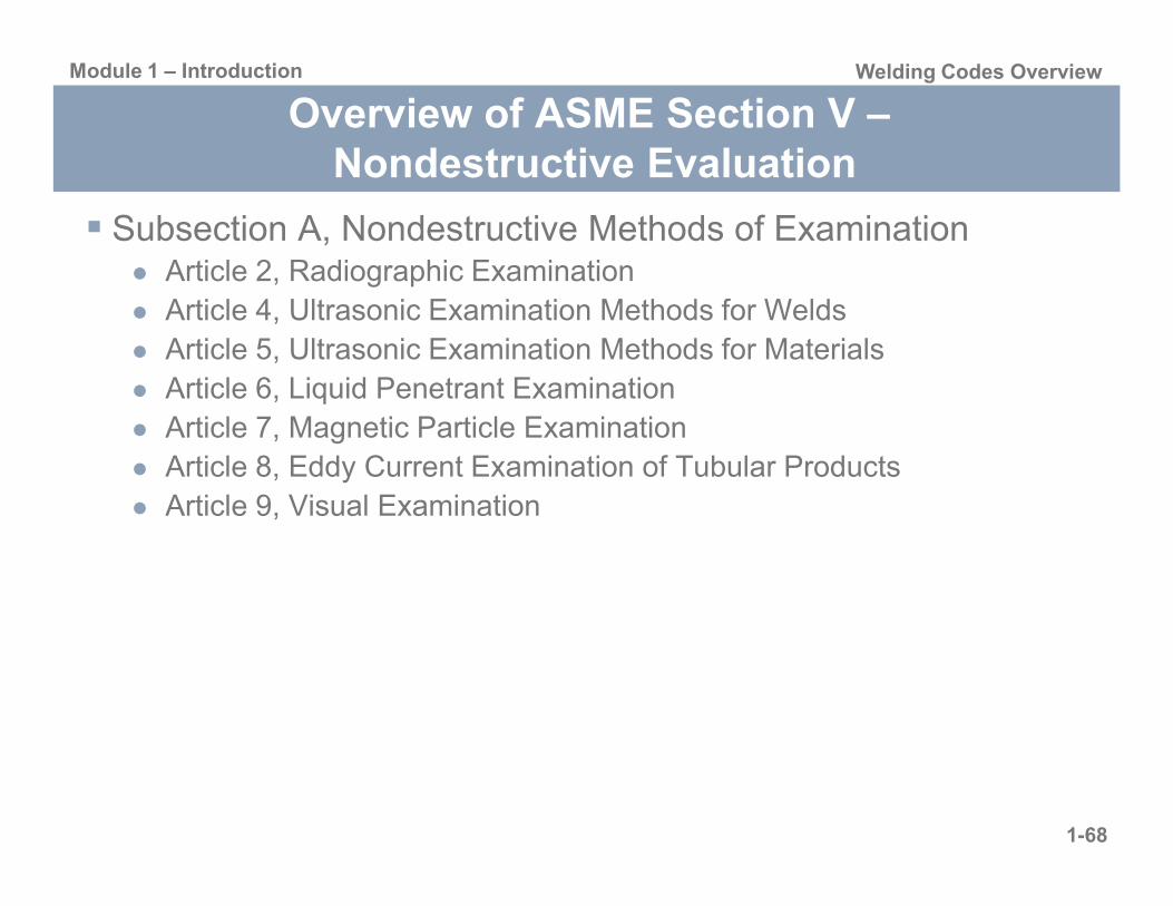
Subsection A, Nondestructive Methods of ExaminationArticle 2, Radiographic ExaminationArticle 4, Ultrasonic Examination Methods for WeldsArticle 5, Ultrasonic Examination Methods for MaterialsArticle 6, Liquid Penetrant ExaminationArticle 7, Magnetic Particle Examination
1-68
Article 8, Eddy Current Examination of Tubular ProductsArticle 9, Visual Examination

Module 1 – Introduction Welding Codes Overview
Overview of ASME Section V –Nondestructive Evaluation
1-69
Module 1 – Introduction Welding Codes Overview
Overview of ASME Section V –Nondestructive Evaluation
1-70

Module 1 – Introduction Welding Codes Overview
Overview of ASME Section V –Nondestructive Evaluation
1-71

Module 1 – Introduction Welding Codes Overview
Overview of ASME Section V –Nondestructive Evaluation
Each nondestructive evaluation article is generally broken into several subsections which vary depending on applicability
ScopeGeneral
States that a written procedure shall be included and gives requirements that should be included in the procedure
Equipment and Materials
1-72
Equipment and MaterialsProvides minimum requirements for the equipment and materialsRefers to other ASME and industry documents
Miscellaneous RequirementsTechniques
Describes different techniques of applying the examination methodFor radiographic examination, the technique could be single-wall or double-wallFor ultrasonic examination, the technique could be straight beam or angle beam

Module 1 – Introduction Welding Codes Overview
Overview of ASME Section V –Nondestructive Evaluation
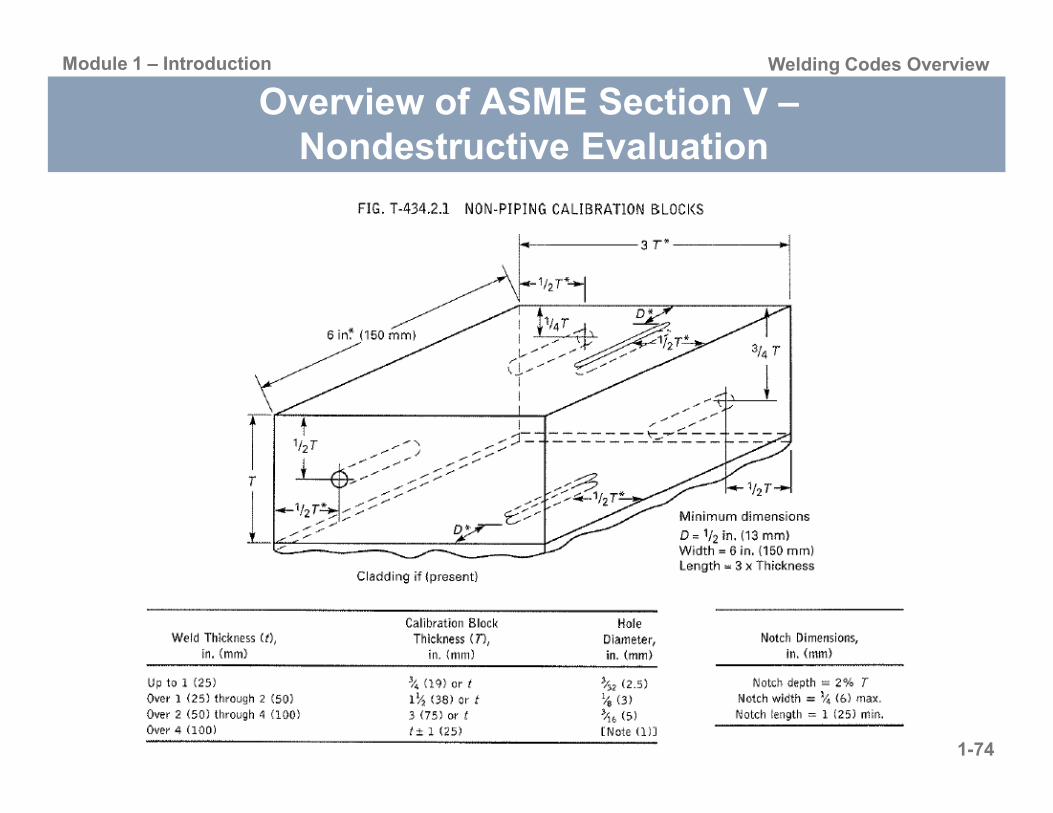
CalibrationDescribes the calibration requirements for the examination method
For radiographic examination, the calibration should include verifying the source size and the requirements for either a densitometer or a step wedge comparisonFor ultrasonic examination, the calibration includes instrument linearity checks and requirement for the calibration block depending on the application
ExaminationIncludes the steps that should be followed when performing an
1-73
Includes the steps that should be followed when performing an examination
EvaluationDescribes how to evaluate the evaluation
For radiographic examination, the evaluation includes making the sure the film is free from blemishes that may mask indications For ultrasonic examination, the evaluation includes determining what flaws require addition evaluation
Not all ultrasonic reflectors indicate flaws, since certain conditions may produce indications that are not relevant
Documentation Defines what should be included in the nondestructive evaluation report
Module 1 – Introduction Welding Codes Overview
Overview of ASME Section V –Nondestructive Evaluation
1-74

Module 1 – Introduction Welding Codes Overview
Overview of ASME Section IX –Welding and Brazing Qualifications
ScopeCovers the qualification of welders, welding operators, brazers, and brazing operators, and the procedures employed in welding or brazing
Referenced by ASME B&PV Code and
1-75
ASME B31 Code for Pressure Piping
Part QW – WeldingArticle I, II, III, IV, V
Part QB – BrazingArticles XI, XII, XIII, XIV
Appendices

Module 1 – Introduction Welding Codes Overview
Overview of ASME Section IX –Welding and Brazing Qualifications
Primary purpose for procedure qualificationTo verify compatibility of materials and techniques to result in a sound weld with acceptable properties
WPS qualified by mechanical testingPQR documentation
To qualify a welding procedure the weld must me destructively tested
1-76
tested
Primary purpose for performance qualification (i.e. welder qualifications)
To verify the ability of an individual to execute a qualified welding procedure specification to produce a sound weld
Can be qualified by mechanical test or NDE

Module 1 – Introduction Welding Codes Overview
Overview of ASME Section IX –Welding and Brazing Qualifications
Part QW WeldingArticle I, Welding General RequirementsArticle II, Welding Procedure QualificationsArticle III, Welding Performance QualificationsArticle IV, Welding DataArticle V, Standard Welding Procedure Specifications (SWPS)
1-77
Part QB BrazingArticle XI, Brazing General RequirementsArticle XII, Brazing Procedure QualificationsArticle XIII, Brazing Performance QualificationsArticle XIV, Brazing Data

Module 1 – Introduction Welding Codes Overview
Overview of ASME Section IX –Welding Qualifications
Article I, Welding General RequirementsQW-100, General
Describes a welding procedure specification (WPS) and procedure qualification record (PQR)
WPS defines the way a weld should be madePQR is the documentation that a weld made using the WPS is acceptable
QW-110, Weld Orientation
1-78
Defines flat, horizontal, overhead and vertical
QW-120, Test Positions for Groove WeldsQW-130, Test Positions for Fillet Welds

Module 1 – Introduction Welding Codes Overview
Typical PQR format
1-79
Module 1 – Introduction Welding Codes Overview
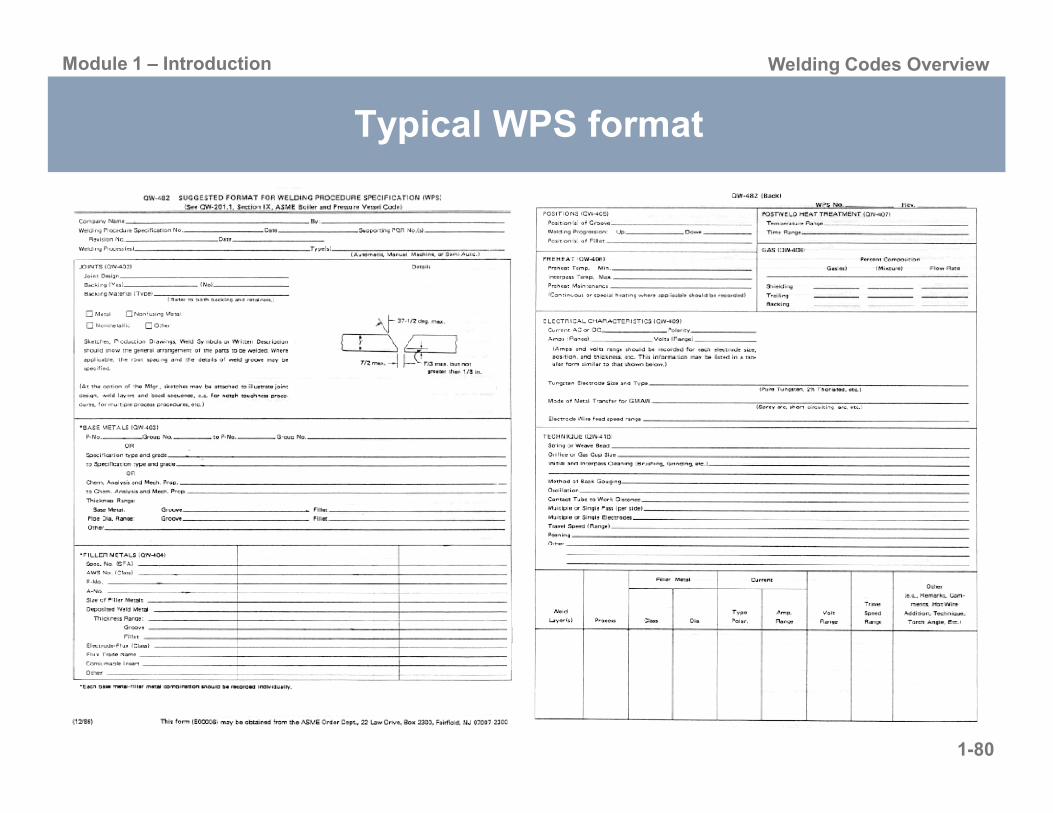
Typical WPS format
1-80

Module 1 – Introduction Welding Codes Overview
Test Positions for Groove Welds in Pipe
1-81

Module 1 – Introduction Welding Codes Overview
Overview of ASME Section IX –Welding Qualifications
Article I, Welding General RequirementsQW-140, Types and Purposes of Tests & Examinations
Describes the types of tests that are used to qualify welding procedures including acceptance criteria
QW-150, Tension TestsQW-160, Guided-Bend TestsQW-170 Notch-Toughness Tests
1-82
QW-170, Notch-Toughness TestsQW-180, Fillet-Weld TestsQW-190, Other Tests and Examinations
Describes NDE inspection methods including acceptance criteria for qualifying procedures and welder qualificationReferences back to Section V
QW-191 Radiographic ExaminationQW-194 Visual ExaminationQW-195 Liquid Penetrant Examination

Module 1 – Introduction Welding Codes Overview
Overview of ASME Section IX –Welding Qualifications
Article II, Welding Procedure Qualifications QW-200, General
Describes what the information belong in the WPS and PQRChanges to the WPS
Changes can be made to nonessential variables without requalificationChanges to essential variables or supplementary essential variable (when required) require requalification
1-83
Manufacturer’s and Contractor’s responsibilityProcesses covered
Oxy-fuel, SMAW, SAW, GMAW, FCAW, GTAW, PAW, ESW, EGW, EBW, Stud, Inertia & Cont. Drive Friction Welding, Resistance Welding, LBW, Flash Welding
Type and number of tests required for procedure qualification

Module 1 – Introduction Welding Codes Overview
Overview of ASME Section IX –Welding Qualifications
1-84
Module 1 – Introduction Welding Codes Overview
Overview of ASME Section IX –Welding Qualifications
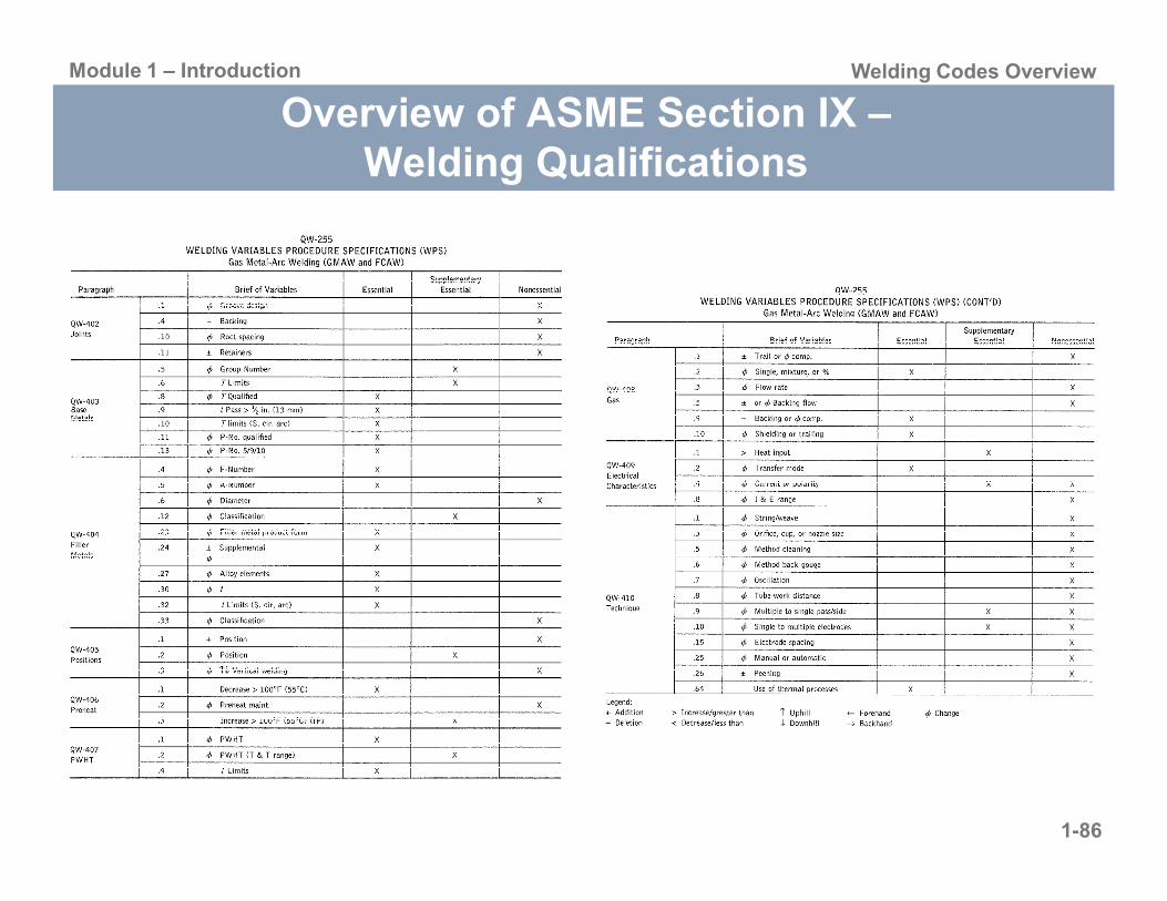
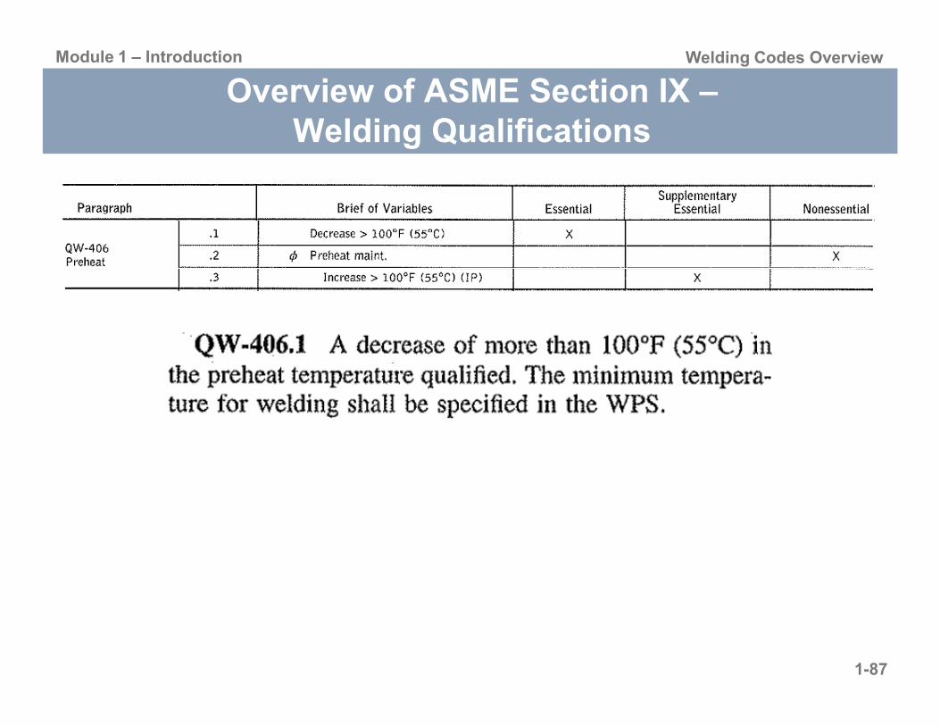
Article II, Welding Procedure Qualifications QW-250, Welding Variables
Lists the essential, nonessential, and supplementary essential variables for each welding process in Section IXEssential variables
Those in which a change is considered to affect the mechanical properties of the weldment, and shall require requalification
1-85
Nonessential variablesThose in which a change may be made in the WPS without requalification
Supplementary essential variablesWhen notch-toughness is required, supplementary essential variables become essential variables
The procedure variables cover all aspects of the weld quality
Module 1 – Introduction Welding Codes Overview
Overview of ASME Section IX –Welding Qualifications
1-86
Module 1 – Introduction Welding Codes Overview
Overview of ASME Section IX –Welding Qualifications
1-87

Module 1 – Introduction Welding Codes Overview
Overview of ASME Section IX –Welding Qualifications
Article III, Welding Performance QualificationsQW-300, General
Welders or welding operators may be qualified by mechanical bending tests, radiography of a test plate, or radiography of the initial production weldWelders are qualified to weld with a process not a specific WPS
QW-320, Retests and Renewal of Qualifications
1-88
QW-350, Welding Variables for WeldersQW-360, Welding Variables for Welding Operators

Module 1 – Introduction Welding Codes Overview
Overview of ASME Section IX –Welding Qualifications
1-89

Module 1 – Introduction Welding Codes Overview
Overview of ASME Section IX –Welding Qualifications
Article IV, Welding DataQW-400, Variables
QW-410, TechniqueQW-420, Material Groupings
P-Numbers
QW-430, F-NumbersQW-440, Weld Metal Chemical Composition
1-90
QW 440, Weld Metal Chemical CompositionQW-450, SpecimensQW-460, GraphicsQW-490, Definitions
Variables are grouped into categoriesSome variables apply to all process
Preheat, Base Metal Thickness, etc.
Some variables apply to one or two processesShielding gas, Shielding Flux, etc.

Module 1 – Introduction Welding Codes Overview
Overview of ASME Section IX –Welding Qualifications
1-91
Module 1 – Introduction Welding Codes Overview
Overview of ASME Section IX –Welding Qualifications
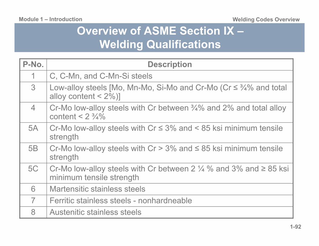
P-No. Description
1 C, C-Mn, and C-Mn-Si steels
3 Low-alloy steels [Mo, Mn-Mo, Si-Mo and Cr-Mo (Cr ≤ ¾% and total alloy content < 2%)]
4 Cr-Mo low-alloy steels with Cr between ¾% and 2% and total alloy content < 2 ¾%
1-92
5A Cr-Mo low-alloy steels with Cr ≤ 3% and < 85 ksi minimum tensile strength
5B Cr-Mo low-alloy steels with Cr > 3% and ≤ 85 ksi minimum tensile strength
5C Cr-Mo low-alloy steels with Cr between 2 ¼ % and 3% and ≥ 85 ksi minimum tensile strength
6 Martensitic stainless steels
7 Ferritic stainless steels - nonhardneable
8 Austenitic stainless steels
Module 1 – Introduction Welding Codes Overview
Overview of ASME Section IX –Welding Qualifications
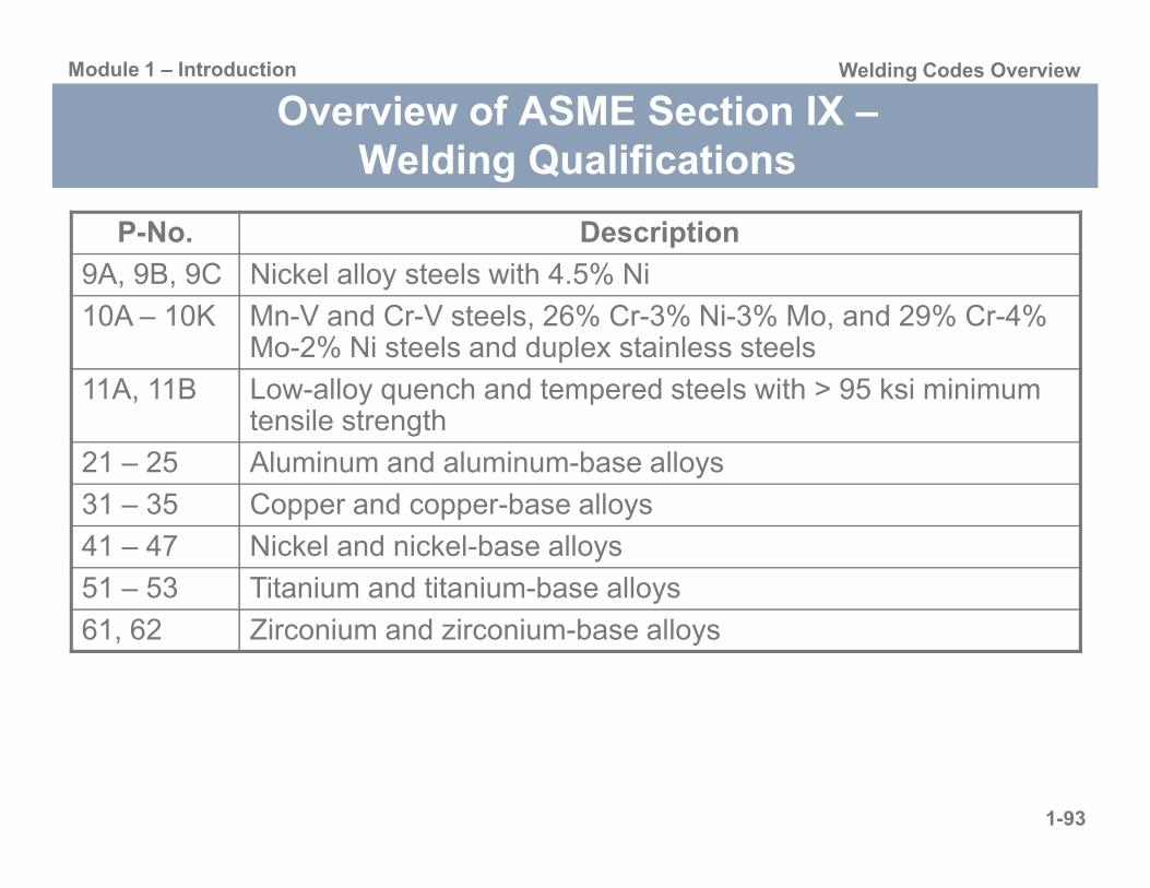
P-No. Description
9A, 9B, 9C Nickel alloy steels with 4.5% Ni
10A – 10K Mn-V and Cr-V steels, 26% Cr-3% Ni-3% Mo, and 29% Cr-4% Mo-2% Ni steels and duplex stainless steels
11A, 11B Low-alloy quench and tempered steels with > 95 ksi minimum tensile strength
1-93
21 – 25 Aluminum and aluminum-base alloys
31 – 35 Copper and copper-base alloys
41 – 47 Nickel and nickel-base alloys
51 – 53 Titanium and titanium-base alloys
61, 62 Zirconium and zirconium-base alloys

Module 1 – Introduction Welding Codes Overview
Overview of ASME Section IX –Welding Qualifications
Article V, Standard Welding Procedure Specifications (SWPSs)
SWPSs that may be used for Section IX are listed in Appendix EAWS B2.1, Standard Welding Procedure Specifications
Each is specific to the combination of base materials, welding process(es), and welding filler metals covered by the scope of eachSupported by procedure qualification records (PQRs)
1-94
Supported by procedure qualification records (PQRs)
If the SWPS, or a similar SWPS hasn’t been used by the manufacturer, than they must weld and test one groove weld test coupon following the SWPS
Additional SWPSs that are similar may be used without demonstrationLimitations apply

Module 1 – Introduction Welding Codes Overview
Overview of ASME Section XI – Rules for Inservice Inspection of Nuclear Power Plant Components
ASME Section XI is separated into three divisions depending on application
Division 1, Rules for Inspection and Testing of Components of Light-Water Cooled Reactors
IWA, General requirementsIWB, Requirements for Class 1 IWC Requirements for Class 2
1-95
IWC, Requirements for Class 2 IWD, Requirements for Class 3 IDE, Requirements for Class MCIWF, Requirements for SupportsIWL, Requirements for Concrete ComponentsMandatory AppendicesNon-Mandatory Appendices
Division 2, Rules for Inspection and Testing of Components of Gas-Cooled ReactorsDivision 3, Rules for Inspection and Testing of Components of Liquid Metal Cooled Reactors
Module 1 – Introduction Welding Codes Overview
Overview of ASME Section XI – Rules for Inservice Inspection of Nuclear Power Plant Components
Division 1, Rules for Inspection and Testing of Components of Light-Water Cooled Reactors
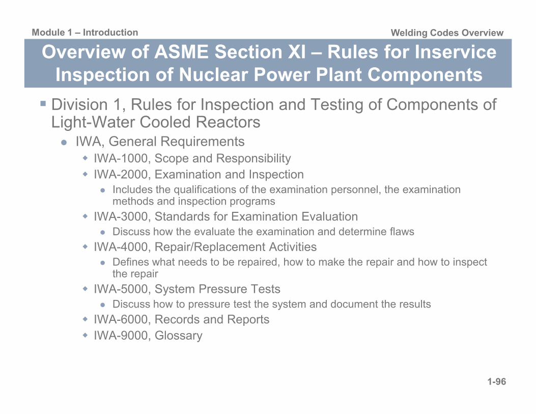
IWA, General RequirementsIWA-1000, Scope and ResponsibilityIWA-2000, Examination and Inspection
Includes the qualifications of the examination personnel, the examination methods and inspection programs
1-96
IWA-3000, Standards for Examination EvaluationDiscuss how the evaluate the examination and determine flaws
IWA-4000, Repair/Replacement ActivitiesDefines what needs to be repaired, how to make the repair and how to inspect the repair
IWA-5000, System Pressure TestsDiscuss how to pressure test the system and document the results
IWA-6000, Records and ReportsIWA-9000, Glossary

Module 1 – Introduction Welding Codes Overview
Overview of ASME Section XI – Rules for Inservice Inspection of Nuclear Power Plant Components
Division 1, Rules for Inspection and Testing of Components of Light-Water Cooled Reactors
IWB, Class 1 ComponentsIWB-1000, Scope and ResponsibilityIWB-2000, Examination and Inspection
Defines how and when to inspect
IWB-3000 Acceptance Standards
1-97
IWB 3000, Acceptance StandardsProvides descriptions of acceptable flaws and methods to analysis flaws
IWB-5000, System Pressure TestsDiscuss how to pressure test the system and document the results
IWC-XXXX, Class 2 Components and IWD-XXXX, Class 3 Components
Generally IWC and IWD have much less detail than IWB, and IWC and IWD will frequently refer user to IWB

Module 1 – Introduction Welding Codes Overview
Overview of ASME Section XI – Rules for Inservice Inspection of Nuclear Power Plant Components
Division 1, Rules for Inspection and Testing of Components of Light-Water Cooled Reactors
IWE-XXXX, Requirements for Class MC and Metallic Liners of Class CC Components of Light-Water Cooled PlantsIWF-XXXX, Requirements for Class 1, 2, 3 and MC component supports of Light-Water Cooled Plants IWL-XXXX Requirements for Class CC Concrete Components of
1-98
IWL-XXXX, Requirements for Class CC Concrete Components of Light-Water Cooled Plants Appendices
Mandatory (I-X)Nonmandatory (A-R)

Module 1 – Introduction Welding Codes Overview
Overview of ASME B31.1 – Power Piping
Chapter I, Scope and Definitions Chapter II, Design Chapter III, MaterialsChapter IV, Dimensional Requirements Chapter V Fabrication
1-99
Chapter V, Fabrication, Assembly, and ErectionChapter VI, Inspection, Examination, and TestingChapter VII, Operation and MaintenanceMandatory AppendicesNonmandatory Appendices

Module 1 – Introduction Welding Codes Overview
Overview of ASME B31.1 – Power Piping
Chapter I, Scope and Definitions The code includes piping found in electric power generating stations, industrial and institutional plants, geothermal heating systems, and central and district heating and cooling systems
Includes but not limited to steam, water, oil, gas, and air serviceWhere steam or vapor is generated at a minimum pressure 15 psigWhere high temperature water is generated at a minimum pressure of 160 psig
d/ i i t t f 250ºF (120ºC)
1-100
and/or a minimum temperature of 250ºF (120ºC)
Defines what applications are not covered by B31.1Components covered by Sections of the ASME Boiler and Pressure Vessel CodeSteam and condensate piping design for 15 psig or less, or hot water systems designed for 30 psig or lessTowers, building frames, tanks, mechanical equipment, instruments, and foundationsMany other applications

Module 1 – Introduction Welding Codes Overview
Overview of ASME B31.1 – Power Piping
1-101

Module 1 – Introduction Welding Codes Overview
Overview of ASME B31.1 – Power Piping
Chapter II, Design Design conditions are define pressure, temperatures and various forces applicable to the design of power piping systems
Design for the most severe conditions
Includes design criteria for piping and components in the piping system
Temperature-Pressure Ratings
1-102
Temperature Pressure RatingsAllowable stressWeld joint efficiency factorsReinforcement of branch connectionsValve requirementsFlange, bolting, facing and gasket requirementsPipe supports

Module 1 – Introduction Welding Codes Overview
Overview of ASME B31.1 – Power Piping
Chapter III, MaterialsRefers to ASME Section II, ASTM Specifications, and numerous other industry standards for the type and product form of materials using in piping systemsRefers to tabulated stress values in Appendix A
Specifies the difference between listed materials, unlisted materials and unknown materials
1-103
Describes limitations of different material typesTemperature limitationsPressure limitations
Chapter IV, Dimensional Requirements Refers to other ASME Sections, other ASTM Specifications, and numerous other industry standards for the dimensional tolerances of materials using in piping systems

Module 1 – Introduction Welding Codes Overview
Overview of ASME B31.1 – Power Piping
Chapter V, Fabrication, Assembly, and ErectionAddress specific requirements related to fabrication, assembly, and erection which include welding and brazing
The qualification of welding procedures and welder and welding operators shall conform to the requirements of the ASME Section IX
Each employer shall be responsible for qualifying any WPS; however a WPS qualified by a technically competent group or agency could be used if approved by the owner
1-104
by the ownerEach employer shall be responsible for qualifying all the welders and welding operators employed by him; however the employer can accept qualification from previous employers if accepted by the owner
The welding materials shall conform to ASME Section II Part CList visual weld contour criteria including some acceptable fillet weld sizesPreheat and PWHT RequirementsAssembly guidance for other then welded joints

Module 1 – Introduction Welding Codes Overview
Overview of ASME B31.1 – Power Piping
Chapter VI, Inspection, Examination, and Testing Listed the NDE methods that are allowed
Visual ExaminationMagnetic Particle ExaminationLiquid Penetrant ExaminationRadiographyUltrasonic Inspection
1-105
Ultrasonic Inspection
States each examination method shall be performed in accordance with ASME Section VGives the construction acceptance criteria for each NDE method
The construction acceptance criteria may be different than the qualification acceptance criteria
Personnel who perform nondestructive examination of welds shall be qualified and certified for each examination method
References ASME Section V for personnel qualification
Provides guidance for pressure testing

Module 1 – Introduction Welding Codes Overview
Overview of ASME B31.1 – Power Piping
1-106

Module 1 – Introduction Welding Codes Overview
Overview of ASME B31.1 – Power Piping
Chapter VI, Inspection, Examination, and Testing
1-107
Module 1 – Introduction Welding Codes Overview
Overview of ASME B31.1 – Power Piping
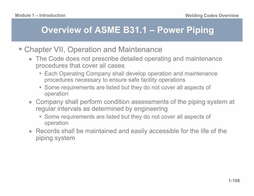
Chapter VII, Operation and MaintenanceThe Code does not prescribe detailed operating and maintenance procedures that cover all cases
Each Operating Company shall develop operation and maintenance procedures necessary to ensure safe facility operationsSome requirements are listed but they do not cover all aspects of operation
1-108
Company shall perform condition assessments of the piping system at regular intervals as determined by engineering
Some requirements are listed but they do not cover all aspects of operation
Records shall be maintained and easily accessible for the life of the piping system