welding, cutting and brazing noaa web based training
TRANSCRIPT

Welding, Cutting and Brazing
NOAA Web based traininghttp://www.labtrain.noaa.gov/default.htm

Introduction
Welding, cutting, and brazing are exceptionally dangerous. Compressed gases are often used to create an extremely hot flame. Different welding techniques can cause other hazards.
The welder can be injured or cause damage to the work area in numerous ways including fire, explosion, gas, and fume hazards.
Good work practices must be followed in all welding, cutting, and brazing techniques to prevent injuries, fires, and explosions.
This module covers the following sections:
Compressed Gases General Requirements Oxygen-Fuel Gas Welding and Cutting Arc Welding and Cutting Resistance Welding.
Introduction - Objectives
At the end of this Welding, Cutting, and Brazing module, you should be able to:
Understand the general requirements concerning compressed gases Identify the general safety requirements for all types of welding Understand the general characteristics for the various types of welding Identify the specific safety requirements for:
Oxygen-fuel gas welding and cutting Arc welding and cutting Resistance welding.
Compressed Gases - Introduction
Many welding and cutting operations require the use of compressed gases. To understand these hazards, we must understand that compressed gases are stores of potential energy. It takes energy to compress and confine the gas. That energy is stored until purposely released to perform useful work or until accidentally released by container failure or other causes.
Some compressed gases, acetylene for example, have high flammability characteristics. Flammable compressed gases, therefore, have additional stored energy besides simple compression-release energy. Other compressed gases, such as nitrogen, have simple asphyxiating properties. Some compressed gases, such as oxygen, can augment or compound fire hazards.

Compressed Gases - Introduction
Compressed gases are regulated by many standards. Two primary standards are:
29 CFR 1910 Subpart Q – Welding, Cutting, and Brazing – covers the handling, storage, and use of compressed gases, such as oxygen- fuel gas, when they are consumed in the welding process.
29 CFR 1910 Subpart H – Hazardous Materials, 1910.101 - 1910.105 – covers the general requirements for the handling, storage, and use of compressed gases other than those consumed in the welding process. The General Requirements section of 1910.101 is concerned with:
Cylinder inspection to include required markings Handling, storage, and utilization Installation and maintenance of safety relief
devices

Compressed Gases – General Requirements
In addition to the Occupational Safety and Health Administration (OSHA) regulations found in Subparts Q and H of 29 CFR 1910 there are other applicable regulations and information. These include the Department of Transportation (DOT) regulations, and the Compressed Gas Association (CGA) pamphlets. These sources provide the requirements for the general category of compressed gases and certain specific compressed gases.
An important aspect of these regulations is the safety of compressed gas storage containers. Specific requirements are made of employers for the inspection of the compressed gas cylinders. Visual inspections are required to ensure that the cylinders are safe. The next page will go into more detail regarding visual examinations of compressed gas storage containers and the safety of these containers.

Compressed Gases – General Requirements
Employees shall determine that compressed gas cylinders under their control are in a safe condition to the extent that this can be determined by visual inspection. Visual and "other" inspections are required, but "other" inspections are not defined. These inspections must be conducted as prescribed in the Hazardous Materials Regulations of the DOT contained in 49 CFR Parts 171-179 and 14 CFR Part 103. Where these regulations are not applicable, these inspections shall be conducted in accordance with CGA Pamphlets C-6 and C-8.
According to DOT regulations: "A cylinder that leaks, is bulged, has defective valves or safety devices, bears evidence of physical abuse, fire or heat damage, or detrimental rusting or corrosion, must not be used unless it is properly repaired and requalified as prescribed in these regulations."
The term "cylinder" is defined as a pressure vessel designed for pressures higher than 40 psia (pounds per square inch absolute) and having a circular cross section. It does not include a portable tank, multi-unit tank car tank, cargo tank, or tank car.

DOT Marking Requirements
Each DOT marking identified on this page must appear on all cylinders and must be maintained so that it is legible.
The circled numbers on the graphic correspond to the numbered definitions provided below.
1. ICC or DOT marking may appear: "ICC": Pre-existing marking – "ICC 3AA2015""3AA" - specification from 49 CFR 178.37"2015" - marked service pressure."DOT": new manufacture marking must read "DOT. 49 CFR 171.14."
2. "A35798641": Serial number - no duplications permitted with any particular symbol- serial number combinations.
3. "PST": Symbol of manufacturer, user, or purchaser. 4. "6 56": date of manufacture. Month and year. " Ø ": disinterested inspector's
official mark. 5. "+": indicates cylinder may be 10% overcharged per 49 CFR 173.302(c). 6. "5-61" and "5-66": Retest dates. 7. "*" (5 pointed star 0: indicates ten year retest interval.
See 49 CFR 173.34(e)(15).

Compressed Gases – General Requirements
In addition to the guidance in the OSHA regulations, Compressed Gas Association (CGA) pamphlets determine requirements for handling, storing, and using compressed gases in cylinders, portable tanks, rail tankcars, and motor vehicle cargo tanks. They also identify how to install and maintain required pressure relief valves on these containers.
The in-plant handling, storage, and utilization of all compressed gases in cylinders, portable tanks, rail tankcars, and motor vehicle cargo tanks shall be in accordance with CGA Pamphlet P-1.
Compressed gas cylinders, portable tanks, and cargo tanks shall have pressure relief devices installed and maintained in accordance with CGA Pamphlets S-1.1 and S-1.2.

Compressed Gases – Specific Gases
The OSHA regulations contain some sections regulating specific compressed gases, including:
Acetylene Hydrogen Oxygen Nitrous oxide Anhydrous ammonia Liquefied petroleum gases.
Other compressed gases are in common use and fall under regulation Subpart H, 1910.101. Examples include chlorine, vinyl chloride, sulfur dioxide, methyl chloride, hydrogen sulfide, ethane, compressed air, and nitrogen.

General Requirements - Introduction
The General Requirements section, 1910.252 provides information about protecting individuals during welding, cutting, or brazing operations. This section contains the three topics listed on the left.
Protection of the individual includes measures taken to:
Prevent fires from occurring Eliminate fires if they occur Protect personnel by providing appropriate
clothing and equipment Protect personnel when welding or cutting
containers Protect personnel working in confined
spaces.

General Requirements – Fire Prevention and Protection
Fire prevention and protection include basic precautions, special precautions, and safety precautions for the unique situations involving welding and cutting containers, and welding in confined spaces.
The basic precautions for fire prevention in welding, cutting, and brazing focus on removal of fire hazards. They include the following:
If the object to be welded or cut cannot readily be moved, all movable fire hazards in the vicinity shall be taken to a safe place
If the object to be welded or cut cannot be moved and if all the fire hazards cannot be removed, then guards shall be used to confine the heat, sparks, and slag, and to protect the immovable fire hazards
If the above requirements cannot be met, then welding and cutting shall not be performed.

General Requirements – Fire Prevention and Protection
Complying with the basic precautions for prevention of fires in welding is not enough. Special precautions must also be taken. These include having the proper fire extinguishing equipment available and having fire watchers present, if needed.
Suitable fire extinguishing equipment shall be maintained in a state of readiness for instant use. Such equipment may consist of pails of water, buckets of sand, hoses, or portable extinguishers depending upon the nature and quantity of the combustible material exposed.
Fire watchers are required whenever welding or cutting is performed in locations where more than a minor fire might develop, or where any of the following conditions exist:
Appreciable combustible materials, in building construction or contents, closer than 35 feet to the point of operation
Appreciable combustible materials more than 35 feet away, but are easily ignited by sparks.
A fire watch shall be maintained for at least a half hour after completion of welding or cutting operations to detect and extinguish possible smoldering fires.

General Requirements – Fire Prevention and Protection
Even if all of the special precautions have been taken, there are still certain situations in which welding, cutting, or brazing are not allowed.
Cutting or welding shall not be permitted in:
Areas not authorized by management Buildings with impaired sprinkler systems The presence of explosive atmospheres (mixtures of flammable
gases, vapors, liquids, or dusts with air) Locations where explosive atmospheres may develop, such as:
Inside unclean or improperly prepared tanks or equipment which have previously contained such materials (flammable gasses, vapors, liquids, or dusts)
Areas with an accumulation of combustible dusts.

General Requirements – Fire Prevention and Protection
Welding and cutting certain containers may constitute a special situation that requires additional safety precautions beyond basic and special precautions.
No welding, cutting, or other hot work shall be performed on used drums, barrels, tanks, or other containers until they have been thoroughly cleaned.
Cleaning must remove all flammable materials present or any substances such as greases, tars, acids, or other materials which might produce flammable or toxic vapors when subjected to heat.
Any pipeline or connections to the drum or vessel being welded shall be disconnected or blanked.

General Requirements – Fire Prevention and Protection
Working in confined spaces involves additional safety precautions beyond the basic and special precautions.
A confined space is defined in 29 CFR 1910.252 as a relatively small or restricted space such as a tank, boiler, pressure vessel, or small compartment of a ship.
Adequate ventilation is a prerequisite to work in confined spaces.
When welding or cutting is being performed in any confined space, the gas cylinders and welding machines shall be left on the outside. When arc welding is to be suspended for any substantial period of time, such as during lunch or overnight, all electrodes shall be removed from the holders. The holders shall be carefully located so that accidental contact cannot occur and the machine shall be disconnected from the power source.

General Requirements – Fire Prevention and Protection
When suspending gas welding or cutting operations, eliminate the possibility of gas escaping through the nozzle by closing the torch valves. The gas supply to the torch must be positively shut off at some point outside the confined area whenever the torch is not to be used for a substantial period of time, such as during lunch hour or overnight. Where practicable, the torch and hose shall also be removed from the confined space.
Where welders must enter a confined space through a manhole or other small opening, means shall be provided for quickly removing them in case of emergency. An attendant with a pre-planned rescue procedure shall be stationed outside to observe the welder at all times and shall be capable of putting rescue operations into effect.

General Requirements – Protection of Personnel
Protection of personnel focuses on protecting the welder from hazards other than general fire protection. Protection of personnel in welding or cutting operations can involve fall protection, eye protection, and protective clothing.
When working at heights, a welder or helper working on platforms, scaffolds, or runways shall be protected against falling through the use of:
Railings Safety belts Life lines Some equally effective safeguards.

General Requirements – Protection of Personnel
Welding, cutting, or brazing operations conducted without proper eye protection create a serious eye injury hazard.
Helmets and hand shields shall be arranged to protect the face, neck, and ears from direct radiant energy from the arc. They shall be used during all arc welding or arc cutting operations, excluding submerged arc welding. helpers or attendants shall be provided with proper eye protection.
Helmets and hand shields shall be made of a material which is an insulator for heat and electricity. Helmets, shields, and goggles shall not be readily flammable and shall be capable of withstanding sterilization.
Where the work permits, the welder should be enclosed in an individual booth or in a non-combustible screen painted with a finish of low reflectivity such as zinc oxide (an important factor for absorbing ultra-violet radiation) and lamp black. Booths and screens shall permit circulation of air at floor level. People adjacent to the welding areas shall be protected from the rays by non-combustible or flameproof screens or shields or shall be required to wear appropriate goggles.

General Requirements – Protection of Personnel
Because of the danger of burns and clothing catching fire, employees exposed to the hazards created by welding, cutting, or brazing operations shall be protected by personal protective equipment in accordance with the requirements of 29 CFR 1910.132.
Appropriate protective clothing required for any welding operation will vary with the size, nature, and location of the work to be performed. Welders should always select clothing materials which will provide maximum protection from sparks and hot metal.
The shirt should have full sleeves, no pockets, and should be worn outside the trousers with collar buttoned. The trousers should have no cuffs and should extend well down to the safety shoes. Safety shoes and fire-resistant gauntlet gloves are also needed.

General Requirements – Health Protections and Ventilation
Regardless of the precautionary measures taken, some materials require special ventilation because they are particularly hazardous. Mechanical ventilation and other specific control measures are required when welding or cutting is done with the following materials:
Fluorine compounds Zinc Lead Beryllium Cadmium Mercury Cleaning compounds Stainless steel

Oxygen-Fuel Gas Welding and Cutting - Introduction
In this Welding, Cutting, and Brazing module, three specific types of welding are covered. These are listed below:
Oxygen-fuel gas welding and cutting Arc welding and cutting Resistance welding.
This section deals specifically with oxygen-fuel gas welding and cutting. The Oxygen-Fuel Gas Welding and Cutting section is based on 29 CFR 1910.253. This section provides information about the five topic areas that are listed to the left.
Each topic is presented with guidance information so that you will be able to prevent accidents and promote work safety when welding or cutting.

Oxygen-Fuel Gas Welding and Cutting - Introduction
General Requirements of Oxygen-Fuel Gas Welding and Cutting, 29 CFR 1910.253, focuses on using acetylene safely.
Under no conditions shall acetylene be generated, piped (except in approved cylinder manifolds), or utilized at a pressure in excess of 15 pounds per square inch gauge (psig) or 30 pounds per square inch absolute (psia). The 30 psia limit is intended to prevent unsafe use of acetylene in pressurized chambers such as caissons, underground excavations, or tunnel construction.
Absolute pressure is equal to gauge pressure plus atmospheric pressure, which at sea level averages 14.7 pounds per square inch (psi). Thus, at sea level, a gauge pressure reading of 15 psi is equal to an absolute pressure of 29.7 psi.
This requirement is not intended to apply to storage of acetylene dissolved in a suitable solvent in cylinders manufactured and maintained according to DOT requirements, or to acetylene for chemical use.
Oxygen-Fuel Gas Welding and Cutting - Introduction
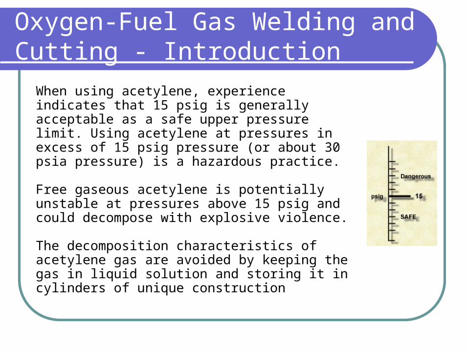
When using acetylene, experience indicates that 15 psig is generally acceptable as a safe upper pressure limit. Using acetylene at pressures in excess of 15 psig pressure (or about 30 psia pressure) is a hazardous practice.
Free gaseous acetylene is potentially unstable at pressures above 15 psig and could decompose with explosive violence.
The decomposition characteristics of acetylene gas are avoided by keeping the gas in liquid solution and storing it in cylinders of unique construction
Oxygen-Fuel Gas Welding and Cutting - Introduction
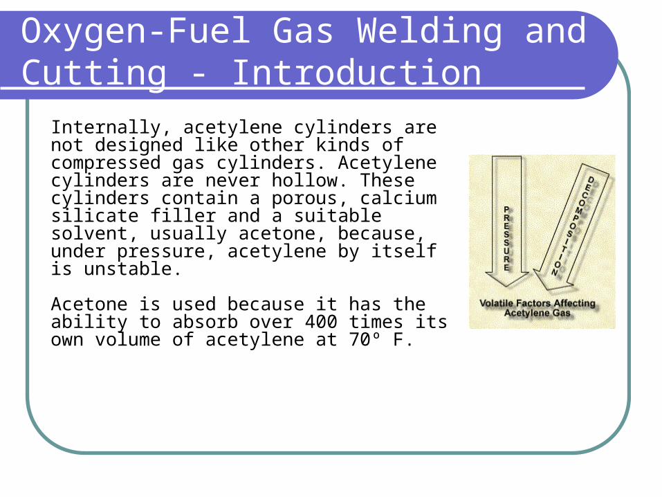
Internally, acetylene cylinders are not designed like other kinds of compressed gas cylinders. Acetylene cylinders are never hollow. These cylinders contain a porous, calcium silicate filler and a suitable solvent, usually acetone, because, under pressure, acetylene by itself is unstable.
Acetone is used because it has the ability to absorb over 400 times its own volume of acetylene at 70º F.

Calcium Silicate
Millions of microscopic pores make up the calcium silicate filler. Although it appears to fill the steel shell, approximately 90 percent of the filler's volume consists of "pore space" for holding and evenly distributing the acetylene/acetone solution.
When absorbed in this filler, the acetylene is divided into such small units that, should acetylene decomposition take place in one pore, the heat released is not enough to raise the temperature of the acetylene in surrounding pores to the point where it, too, will decompose.
Acetylene is usually supplied in cylinders which have a capacity of up to 300 cubic feet of dissolved gas under pressure of 250 psig at 70º F.

Oxygen-Fuel Gas Welding and Cutting - Cylinders
Regardless of the interior construction of the cylinders, all portable cylinders used for the storage and shipment of compressed gases shall be constructed and maintained in accordance with the regulations of the U.S. Department of Transportation, 49 CFR Parts 171-179.
When using or handling cylinders and containers, it is important to know about: Cylinder approval and marking Storage of cylinders Operating procedures.
Compressed gas cylinders shall be legibly marked, for the purpose of identifying the gas content, with either the chemical or trade name of the gas. Such marking shall be by means of stenciling, stamping, or labeling, and shall not be readily removable. Whenever practical, the marking shall be located on the shoulder of the cylinder.

Oxygen-Fuel Gas Welding and Cutting - Cylinders
Appropriate marking not only enables proper use, but also assists in proper storage. The following information generally applies to all cylinders:
Cylinders shall be kept away from radiators and other sources of heat Inside of buildings, cylinders shall be stored in a well-protected, well-ventilated, dry location, at least 20 feet (6.1 m) from highly combustible materials. Cylinders should be stored in assigned places away from elevators, stairs, or gangways, or other areas where they might be knocked over or damaged by passing or falling objects, or subject to tampering Empty cylinders shall have their valves closed Valve protection caps, where the cylinder is designed to accept a cap, shall always be in place, hand-tight, except when cylinders are in use or connected for use. The valve protection cap is designed to take the blow in case the cylinder falls.
Additional requirements exist for the storage of fuel gas and oxygen cylinders.

Fuel Gas Cylinders - Storage Requirements
Inside a building, stored cylinders shall be limited to a total gas capacity of 2,000 cubic feet (56 m3) or 300 pounds of liquefied petroleum gas. This limitation does not apply to cylinders that are in actual use or are attached ready for use.
Acetylene cylinders shall be stored valve end up. If the cylinder is on its side, acetone may leak out and create a dangerous condition.

Oxygen Cylinders
Oxygen cylinders in storage shall be separated from fuel-gas cylinders or combustible materials (especially oil or grease), a minimum distance of 20 feet (6.1 m) or by a non-combustible barrier at least 5 feet (1.5 m) high having a fire-resistance rating of at least one-half hour.
This requirement is intended to reduce the possibility of any fire support when a fire occurs among the fuel gas storage.

Oxygen-Fuel Gas Welding and Cutting - Cylinders
The potential dangers related to cylinders containing compressed gases require that cylinders be stored and operated properly. Operation must emphasize the absence of oily or greasy substances. Follow these rules of operation:
Cylinders, cylinder valves, couplings, regulators, hose, and apparatus shall be kept free from oily or greasy substances
Oxygen cylinders or apparatus shall not be handled with oily hands or gloves
A jet of oxygen must never be permitted to strike an oily surface, greasy clothes, or enter a fuel oil or other storage tank.

Oxygen-Fuel Gas Welding and Cutting - Cylinders
The valve outlet and regulator are two critical components of compressed gas cylinders that must be used properly.
Valve protection caps protect the valve from damage and oil and grease. The valve-protection cap shall not be used for lifting cylinders from one vertical position to another. The cap may accidentally and suddenly come loose.
Should a cylinder without a cap fall or be knocked over, the valve may be damaged or sheared off, causing a sudden release of pressure.
If the valve outlet of a cylinder becomes clogged with ice, thaw with warm – not boiling – water.

Oxygen-Fuel Gas Welding and Cutting - Cylinders
Like the valve outlet, the regulator must be carefully protected.
Unless cylinders are secured on a special truck, regulators shall be removed and valve-protection caps, when provided for, shall be put in place before cylinders are moved.
Cylinders not having fixed hand wheels shall have keys, handles, or non-adjustable wrenches on valve stems while these cylinders are in service.
Unless connected to a manifold, always attach a regulator to the compressed gas cylinder before use. Make certain that the regulator is compatible for the particular gas and service pressure.
Make sure the regulator is clean and has a clean filter installed in the inlet nipple.

Oxygen-Fuel Gas Welding and Cutting - Cylinders
Before attaching the regulator, remove the protective cap from the cylinder. Stand to one side of the cylinder. Open the cylinder valve slightly for an instant, and then close it. This "cracking" of the cylinder valve will clean the valve of dust or dirt which may have accumulated during storage. Dirt can damage critical parts of a regulator, and may cause a fire or explosion.
Before a regulator is removed from a cylinder valve, the valve shall be closed and the gas released from the regulator.
An acetylene cylinder valve shall not be opened more than one and one-half turns of the spindle. This permits adequate flow of acetylene and allows ready closing of the valve in an emergency situation.

Oxygen-Fuel Gas Welding and Cutting - Manifolding of Cylinders
Sometimes when welding, a portable cylinder is not used as the source of gas. A service pipe system can be used to provide a manifolding effect. Manifolding is the gathering of multiple-line fluid inputs into a single intake chamber. In other words, the combining of gases needed for welding. This can be accomplished through the use of portable outlet headers. Each header will control the flow of a particular gas. Portable outlet headers (shown in purple) consist of the nozzle and hoses that can be connected to a portable cylinder or a service pipe.
Portable outlet headers shall not be used indoors except for temporary service where the conditions preclude a direct supply from outlets located on the service piping system.
Each outlet on the service piping from which oxygen or fuel gas is withdrawn to supply a portable outlet header shall be equipped with a readily accessible shut-off valve (shown in red in the figure).

Oxygen-Fuel Gas Welding and Cutting - Manifolding of Cylinders
Each service outlet on portable outlet headers shall be provided with a valve assembly that includes a detachable outlet seal cap (shown in yellow), chained or otherwise attached to the body of the valve.
The primary reasons for using a seal cap are to protect the outlet pipe thread from damage and to prevent the deposit of oil or grease on the threads.
Many times the caps are not used. Failure to use the seal cap can result in damage to threads and ground seals. This can cause leaky connections

Oxygen-Fuel Gas Welding and Cutting - Service Pipe Systems
Service piping systems must meet all design and installation safety requirements.
Pipe shall be at least Schedule 40 and fittings shall be at least standard weight in sizes up to and including 6-inch nominal. Schedule 40 pipe is standard black iron pipe which has a working pressure of up to 125 psi and is always tested before use. Problems might arise when line extensions are made with other types of pipe or aluminum tubing. Therefore, a close inspection is necessary.
There are special requirements for service pipe systems when using oxygen or acetylene.
Oxygen
Acetylene or Acetylene Compounds

Oxygen When oxygen is supplied to a service piping system from a low pressure oxygen manifold without an intervening pressure regulating device, the piping system shall have a minimum design pressure of 250 psig. A pressure regulating device shall be used at each station outlet when the connected equipment is for use at pressures less than 250 psig.
Acetylene or Acetylene Compounds Piping for acetylene or acetylenic compounds shall be steel or wrought iron. Unalloyed copper shall not be used for acetylene or acetylenic compounds except in listed equipment. Under certain conditions, acetylene forms explosive compounds with copper (as well as silver and mercury).

Oxygen-Fuel Gas Welding and Cutting - Service Pipe Systems
Now that we understand material and design requirements, let’s consider the installation of a service pipe system.
All piping shall be run as directly as practical. It will be protected against physical damage with proper allowance for expansion, contraction, jarring, and vibration.
Pipe laid underground in earth shall be located below the frost line and protected against corrosion.
After assembly, piping shall be thoroughly blown out with air, nitrogen, or carbon dioxide to remove foreign materials. For oxygen piping, only oil-free air, oil-free nitrogen, or oil-free carbon dioxide shall be used

Oxygen-Fuel Gas Welding and Cutting - Service Pipe Systems
Low points in piping carrying moist gas shall be drained into drip pots constructed so as to permit pumping or draining out the condensate at necessary intervals. Drain valves for this purpose shall have outlets closed with screw caps or plugs.
Piping from overhead lines shall have drip pots at each station. These drip pots either have a plug or petcock on the bottom. Underground installations have no draining system.
Open end valves or petcocks shall be used. However, drip pots located out of doors, underground, and not readily accessible, may be controlled by valves if they are equipped with a means to secure them in the closed position.
Pipes leading to the surface of the ground shall be cased or jacketed where necessary to prevent loosening or breaking. Pipes leading to the surface from underground lines have to be secured to prevent breaking or to avoid other damage to them.

Oxygen-Fuel Gas Welding and Cutting - Service Pipe Systems
Another important consideration for underground piping is protection against corrosion. Underground pipe and tubing and outdoor ferrous pipe and tubing shall be covered or painted with a suitable material for protection against corrosion.
Once installation is completed, piping systems shall be tested and proved gas tight at 1½ times the maximum operating pressure, and shall be thoroughly purged of air before being placed in service.
The material used for testing oxygen shall be oil free and non-combustible. Flames shall not be used to detect leaks.

Oxygen-Fuel Gas Welding and Cutting - Pipe System Protection
The entire service pipe system must be protected against build-up of excessive pressure and leaks. This protection is accomplished with:
Protective equipment Regulators Proper hose and hose connections.

Oxygen-Fuel Gas Welding and Cutting - Pipe System Protection
Protective equipment is divided into the two categories listed here. Pressure Relief DevicesPiping Protective Equipment
Pressure Relief Devices
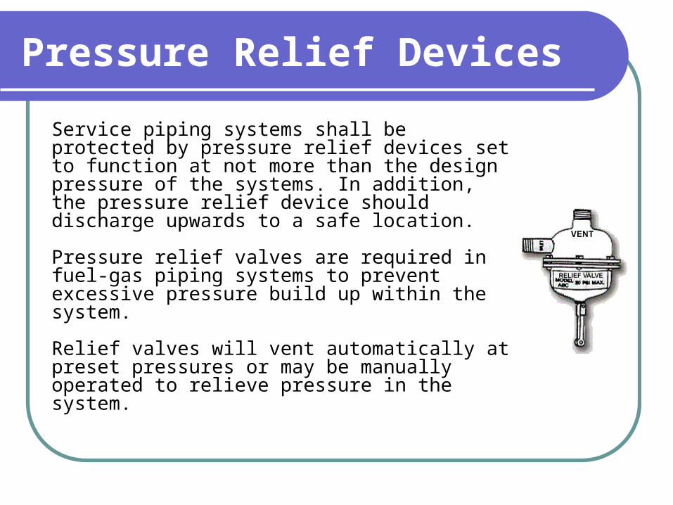
Service piping systems shall be protected by pressure relief devices set to function at not more than the design pressure of the systems. In addition, the pressure relief device should discharge upwards to a safe location.
Pressure relief valves are required in fuel-gas piping systems to prevent excessive pressure build up within the system.
Relief valves will vent automatically at preset pressures or may be manually operated to relieve pressure in the system.

Piping Protective Equipment
Approved protective equipment shall be installed in fuel-gas piping to prevent:
Backflow of oxygen into the fuel-gas supply system Passage of a flash back into the fuel-gas supply system Excessive back pressure of oxygen in the fuel-gas supply system.
The three functions of the protective equipment may be combined in one device or may be provided by separate devices.
The protective equipment in fuel-gas piping systems shall be located either at the main supply line, at the head of each branch line, or at each location where fuel-gas is withdrawn. Protective equipment placed at the main supply provides the best protection. Go to the next page to see a visual comparison of the three locations for safety devices.

Piping Protective Equipment
Protective equipment can be located in the main supply line with one check valve installed before each outlet for the greatest protection, as in Figure 1, or at the head of each branch line plus check valves at each outlet, as in Figure 2, or at each location where fuel-gas is withdrawn with check valves at each outlet, as in Figure 3.

Oxygen-Fuel Gas Welding and Cutting - Pipe System Protection
Another method of controlling pressure involves the use of pressure-reducing regulators. Pressure-reducing regulators shall be used only for the gas and pressures for which they are intended.
When regulators or parts of regulators, including gages, need repair, the work shall be performed by skilled mechanics who have been properly instructed. Most production shops do not have the proper equipment to make repairs. For any equipment repairs or if there are questions about performance reliability, contact the manufacturer.
Gages on oxygen regulators shall be marked "USE NO OIL."

Oxygen-Fuel Gas Welding and Cutting - Pipe System Protection
In addition to using release devices, the system must be designed, using proper hoses, to protect against leaks. The Oxygen hose is green and has a right-hand threaded nut for connecting to the torch. The Acetylene fuel gas hose is usually red (sometimes black) and has a left-hand threaded nut for connecting to the torch.
Hose and hose connections shall be clamped or otherwise securely fastened in a manner that will withstand, without leakage, twice the pressure to which they are normally subjected in service, but in no case less than a pressure of 300 psi. Oil-free air or an oil-free inert gas shall be used for the test.
Hoses showing leaks, burns, worn places, or other defects rendering it unfit for service shall be repaired or replaced. When inspecting hoses, look for charred sections close to the torch. These may have been caused by flash-back. Also check that hoses are not taped up to cover leaks.

Arc Welding and Cutting - Introduction
The second specific type of welding discussed in this module is Arc Welding and Cutting. This Arc Welding and Cutting section provides information about the three topic areas that are listed to the left.
The information presented here will prevent accidents and promote work safety when undertaking arc welding or cutting operations.

Arc Welding and Cutting - Introduction
In the arc welding process, an electric current passing through the welding rod or electrode is forced to jump or arc across a gap. The resulting arc produces the intense heat necessary for the welding or cutting operation.
Arc welding is used to fabricate nearly all types of carbon or alloy steels, the common nonferrous metals, and is indispensable in the repair and reclamation of metallic machine parts.
Arc cutting is primarily used for rough cuts or for scrapping because of the uneven cut that results. It has also been used for underwater cutting in salvaging operations.
While most precautions and safe practices are common to oxy-fuel gas welding, there are some that are unique to either gas or arc welding.

Arc Welding and Cutting - Introduction
Shielding is one of the unique requirements of arc welding.
Experience has shown that welds will have better chemical and physical properties if the air can be kept away from the weld puddle. Such gases as oxygen, hydrogen, and nitrogen, along with water vapor (moisture) all tend to reduce the quality of the weld. Dirt, dust, and metal oxides (contaminants) also reduce the weld quality.
Shielding of the arc preserves the integrity of the weld joint. Shielding is provided either by:
Decomposition of the electrode covering, known as flux A gas (or gas mixture) which may or may not be inert.

Arc Welding and Cutting - Introduction
Arc welding and cutting involves a variety of processes. Some of the more common processes are listed below.
Shielded Metal-Arc Welding (SMAW) Gas Metal Arc Welding (GMAW) Gas Tungsten Arc Welding (GTAW) Flux Cored Arc Welding (FCAW) Submerged Arc Welding (SAW) Arc Cutting Plasma Arc Cutting (PAC) Air Carbon-Arc Cutting (AAC) Arc Gouging

Shielded Metal-Arc Welding (SMAW)
Shielded metal-arc welding is the most widely used type of arc welding, commonly referred to as "stick" welding. In this process, coalescence is achieved by heating with an electric arc between a covered (or coated) electrode and the work surface. Shielding is provided by decomposition of the electrode covering, known as the flux, while filler metal is obtained from the electrode's metal core.

Gas Metal Arc Welding (GMAW)
Gas metal arc welding is commonly known as "MIG" welding. In the gas metal arc welding process, coalescence is achieved by the heat of an electric arc maintained between the end of an electrode and the work surface. Shielding of the arc is provided by a gas (or gas mixture) which may or may not be inert. The electrode is fed continuously to the weld where it is melted in the intense heat of the arc and deposited as weld metal.

Gas Tungsten Arc Welding (GTAW)
Gas tungsten arc welding is commonly known as "TIG" welding. In gas tungsten arc welding, coalescence is achieved by the arc and electrode method except that the tungsten electrode is not consumed. Shielding is provided by an inert gas. This process produces high precision welds.

Flux Cored Arc Welding (FCAW)
Flux cored arc welding is a process which produces coalescence by means of an arc between a continuous consumable electrode and the work surface. Shielding is provided by flux contained within the tubular electrode. Additional shielding may be obtained from a gas or gas mixture.

Submerged Arc Welding (SAW)
In submerged arc welding, coalescence is produced by the heat of an arc between a bare metal electrode and the work surface. The arc is shielded by a blanket of granular, fusible flux. The tip of the electrode and the welding zone are surrounded and shielded by the molten flux and a layer of unused flux in the granular state. In this process, there is no visible evidence of the passage of current between the electrode and the work surface. This eliminates the sparks, spatter, and smoke ordinarily seen in other arc welding processes. Fumes are still produced, but not in quantities generated by other processes.

Arc Cutting
Arc cutting is the general process in which the cutting or removal of metals is done by melting with the heat of an arc between an electrode and the base metal.

Plasma Arc Cutting (PAC)
In plasma arc cutting, the metal is cut by melting a localized area with a constricted arc and removing the molten material with a high velocity jet of hot, ionized gas.

Air Carbon-Arc Cutting (AAC)
Air carbon-arc cutting is a type of arc cutting in which the metal is cut by melting with the heat of an arc, with use of an air stream to facilitate cutting.

Arc Gouging
Arc gouging is an application of arc cutting used to produce a groove or bevel in the metal surface.

Arc Welding and Cutting - Application
When arc welding, either alternating or direct current is used. The AC and DC limits shown below shall not be exceeded.
For AC welding under wet conditions or warm surroundings where perspiration is a factor, the use of reliable automatic controls for reducing no-load voltage is recommended to reduce the shock hazard. Some of the older AC machines do not have an automatic control and are on load all the time. It is easy to receive an electric shock when the equipment is not handled properly.
Alternating Current (AC)
Direct Current (DC)
Manual 80 Volts 100 Volts
Automatic 100 Volts 100 Volts

Arc Welding and Cutting - Installation
Arc welding requires proper installation of equipment. A critical part of installation is ensuring that proper grounding is completed. The frame or case of the welding machine (except engine-driven machines) shall be grounded under the conditions and according to the methods prescribed in Subpart S, Electrical.
Conduits containing electrical conductors shall not be used for completing a work-lead circuit. Pipelines shall not be used as a permanent part of a work-lead circuit, but may be used during construction, extension, or repair providing current is not carried through threaded joints, flanged bolted joints, or caulked joints and that special precautions are used to avoid sparking at connection of the work-lead cable.

Arc Welding and Cutting - Operation and Maintenance
Before starting operations, all connections to the machine shall be checked to make certain that they are properly made. The work lead shall be firmly attached to the work. Magnetic work clamps shall be free from adherent metal particles of spatter on contact surfaces. Coiled welding cable shall be spread out before use to avoid serious overheating and damage to insulation.
During welding operations, cables with splices within 10 feet (3m) of the holder shall not be used. Welders should not coil or loop welding electrode cable around parts of their body.
Cables with damaged insulation or exposed bare conductors shall be replaced. Joining lengths of work and electrode cables shall be done by the use of connecting means specifically intended for that purpose. The connecting means shall have insulation adequate for the service conditions.
Resistance Welding
The third welding process covered in this module is resistance welding. Resistance welding utilizes pressure and heat that is generated in the pieces to be welded by resistance to an electric current.
When conducting resistance welding, all equipment shall be installed by a qualified electrician in conformance with Subpart S, Electrical. If spot and seam welding machines are used, the following precautions must be taken:
All doors and access panels of all resistance welding machines and control panels shall be kept locked and interlocked to prevent access to live portions of the equipment by unauthorized persons.
In all press welding operations, if there is a possibility of the operator's fingers being under the point of operation, effective guards must be used. Examples of effective guards include an electronic eye safety circuit, two hand controls, or protection similar to that prescribed for punch press operations.

Resistance Welding
The hazard of flying sparks shall be, wherever practical, eliminated by installing a shield guard of safety glass or suitable fire-resistant plastic at the point of operation. Additional shields or curtains shall be installed as necessary to protect passing persons from flying sparks.
All foot switches shall be guarded to prevent accidental operation of the machine.
Two or more safety emergency stop buttons shall be provided on all special multi-spot welding machines, including 2-post and 4-post weld presses.
Additionally, all portable welding guns, transformers and related equipment suspended from overhead structures, eye beams, trolleys, etc., shall be equipped with safety chains or cables. Safety chains or cables shall be capable of supporting the total shock load in the event of failure of any component of the supporting system.