welding - amazon s3 · or by applying pressure to the pieces in cold or heated state....
TRANSCRIPT

Topic: - Welding Technology Prepared By: Sandeep Kumar
1
WELDING
Welding is a process of joining two metal pieces as a result of significant diffusion of the atoms of the welded pieces into the joint (weld) region. Welding is carried out by heating the joined pieces to melting point and fusing them together (with or without filler material) or by applying pressure to the pieces in cold or heated state.
Classification of welding processes
Arc weldingo Carbon Arc Welding;o Shielded Metal Arc Welding (SMAW);o Submerged Arc Welding (SAW);o Metal Inert Gas Welding (MIG, GMAW);o Tungsten Inert Gas Arc Welding (TIG, GTAW);o Electroslag Welding (ESW);o Plasma Arc Welding (PAW);
Resistance Welding (RW);o Spot Welding (RSW);o Flash Welding (FW); o Resistance Butt Welding (UW) ;o Seam Welding (RSEW);
Gas Welding (GW);o Oxyacetylene Welding (OAW);o Oxyhydrogen Welding (OHW);o Pressure Gas Welding (PGW);
Solid State Welding (SSW);o Forge Welding (FOW);o Cold Welding (CW);o Friction Welding (FRW);o Explosive Welding (EXW);o Diffusion Welding (DFW);o Ultrasonic Welding (USW);
Thermo-chemical Welding
o Thermit Welding (TW)o Atomic Hydrogen welding.
Radiant energy welding
o Electron Beam Welding (EBW);o Laser Welding (LW).
Commonly Welded Base Metals - Metals can be classified as 1. Ferrous 2. Nonferrous. Ferrous materials contain iron and the one element people use more than all others is Iron. Ferrous materials are the most important metals/alloys in the metal lurgical and mechanical industries because of their very extensive use. Ferrous materials finding day to day welding applications are:

Topic: - Welding Technology Prepared By: Sandeep Kumar
2
1. Wrought Iron.2. Cast Iron.
3. Carbon Steel (Low. Medium and High Carbon Steels).4. Cast Steels. 5. Alloy Steels. 6. Stainless Steels, etc. Nonferrous materials are those that are not iron based. Like ferrous materials, nonferrous materials also find extensive industrial applications. Nonferrous materials finding day to day welding applications are : 7. Aluminium and its alloys. 8. Copper and its alloys.9. Magnesium and its alloys. 10. Nickel and its alloys. 11. Zinc and its alloys, etc
Advantages of Welding -(i) A good weld is as strong as the base metal. (ii) General welding equipment is not very costly. (iii) Portable welding equipments are available. (iv) Welding permits considerable freedom in design. (v) A large number of metals/alloys both similar and dissimilar can be joined by welding. (vi) Welding can join workpieces through spots, as continuous pressure tight seams, end to end and in a number of other configurations. (viii) Welding can be mechanized.Disadvantages of Welding -(i) Welding gives out harmful radiations (light) fumes arid spatter. (ii) Welding results in residual stresses and distortion of the work pieces. (iii) Jigs and fixtures are generally required to hold and position the parts to be welded. (iv) Edge preparation of the workpieces is generally required before welding them. (v) A skilled welder is a must to produce a good welding job.(vi) Welding heat produces metallurgical changes. The structure of the welded joint is not same as that of the parent metal. (vii) A welded joint for many reasons, needs stress relief heat treatment.
Welding Compared to Rivetting and Casting - Bridges, ships and boilers which were previously riveted are now welded. Machine tool beds which were earlier cast are now fabricated using welding. In many fields welding has replaced riveting and casting processes. Some of the reasons, for the same, are as follows: 1. Welding is more economical and is a much faster process as compared to both casting and riveting.2. Fabricated mild steel structures are lighter as compared to (cast) cast iron ones.3. Fabricated mild steel structures have more tensile strength and rigidity as compared to (cast) cast iron ones.
4. Welding can join dissimilar metals and thus in a complicated structure (depending upon strength or other criteria) different parts of the structure can be fabricated with different materials.5. For the same complexity of a component the design of a welded structure is simpler as compared to that of a cast part. Standard rolled sections help considerably in fabricating different structures by welding. 6. Being noiseless as compared to riveting,
Topic: - Welding Technology Prepared By: Sandeep Kumar
3
welding finds extensive use, when making modifications, additions or extensions in hospital buildings.7. Cost of pattern making and storing is eliminated.8. As compared to casting and riveting fewer persons are involved in a welding fabrications.9. Welding fabrication involves inventory, much less as compared to casting and since no patterns are involved, the chances of obsolescence are negligible.10. Against riveted construction welding fabrication involves less cost of handling.
11. Structural shapes not easily obtainable with riveting or casting can be produced by welding without much difficulty.12. Welding design involves lower costs and it is very flexible also.13. Fabrication by welding saves machining costs involved in cast parts. 14. Welded pressure vessels are more (fluid and) pressure tight as compared to riveted ones. Moreover, for pressure tightness, the rivets must be calked.
15. Ratio between weight of weld metal and the entire weight of structure is much lesser than the ratio between the weight of rivets and the entire weight of the structure.Welded structures are comparatively lighter than corresponding riveted ones.16. Cover plates, connecting angles, gusset plates, etc., needed in riveted construction are not required when welding the structures.17. Members of such shapes that present difficulty for riveting can be easily welded.18. Welding can be carried out at any point on a structure, but, riveting always requires enough clearance to be done.19. A welded structure possesses a better finish and appearance than the corresponding riveted structure.20. Layout for punching or drilling of holes is not required in welding.21. Drilling holes in the plates in order to accommodate rivets, breaks material continuity and weakens a riveted structure.22. Cost of standard rolled sections is much less as compared to that of a casting with the result that welded structures involve less material costs.23. Making changes in an already cast or riveted structure is extremely difficult, if not impossible. On the other hand a welded structure can be modified or repaired without much difficulty.24. Welding can produce a 100% efficient joint which is difficult to make by riveting.
25. Riveting high strength steels presents the problem of acquiring high strength steel rivets.26. Old structures can easily be reinforced by welding.Whereas welding claims its supremacy, casting, however has got its own good points. For example,(i) a product is obtained as one piece, ,(ii) thermal effects as in welding are not there,(iii) very heavy and bulky parts like those of power plants and mill housings which are otherwise difficult to fabricate can be cast.
Practical Applications of Welding - Welding has been employed in Industry as a tool for: (a) Regular fabrication of automobile cars, aircrafts, refrigerators, etc. (b) Repair and maintenance work, e.g., joining broken parts, rebuilding Worn out components, etc. A few important applications of welding are listed below:1. Aircraft Construction: (a) Welded engine mounts.(b) Turbine frame for jet engine.

Topic: - Welding Technology Prepared By: Sandeep Kumar
4
(c) Rocket motor fuel and oxidizer thanks.(d) Ducts, fittings, cowling components, etc
2. Automobile Construction:(a) Arc welded car wheels. (b) Steel rear axle housing.(c) Frame side rails.(d) Automobile frame, brackets, etc. 3. Bridges:(a) Pier construction.(b) Section lengths.(c) Shop and field assembly of lengths, etc. 4. Buildings:(a) Column base plates.(b) Trusses.(c) Erection of structure, etc.
5. Pressure Vessels and Tanks:(a) Clad and lined steel plates.(b) Shell construction.(c) Joining of nozzle to the shell, etc. 6. Storage Tanks:(a) Oil, gas and water storage tanks.7. Rail Road Equipment:Locomotive(a) Under frame.(b) Air receiver.(c) Engine.(d) Front and rear hoods, etc. 8. Pipings and Pipelines:(a) Rolled plate piping.(b) Open pipe joints.(c) Oil, gas and gasoline pipe lines, etc.
9. Ships:(a) Shell frames.(b) Deck beams and bulkhead stiffeners. (c) Girders to shells.(d) Bulkhead webs to plating, etc. 10. Trucks and trailers.11. Machine tool frames, cutting tools and dies.12. Household and office furniture. 13. Earth moving machinery and cranes. In addition, arc welding finds following applications in repair and maintenance work: 14. Repair of broken and damaged components and machinery such as tools, punches, dies, gears, shears, press and machine tools frames. 15. Hard facing and rebuilding of worn out or undersized (costly) parts rejected during inspection.16. Fabrication of jigs, fixtures, clamps and other work holding devices.
Welding position

Topic: - Welding Technology Prepared By: Sandeep Kumar
5
PA - flat position
PB - horizontal vertical position
PC - horizontal position
PD - horizontal overhead position
PE - overhead position
PF - vertical up position
PG - vertical down position

Topic: - Welding Technology Prepared By: Sandeep Kumar
6
GAS WELDING PROCESSES
Gas Welding is a welding process utilizing heat of the flame from a welding torch. The torch mixes a fuel gas with Oxygen in the proper ratio and flow rate providing combustion process at a required temperature. The hot flame fuses the edges of the welded parts, which are joined together forming a weld after Solidification.
The flame temperature is determined by a type of the fuel gas and proportion of oxygen in the combustion mixture: 4500°F - 6300°F (2500°C - 3500°C). Depending on the proportion of the fuel gas and oxygen in the combustion mixture, the flame may be chemically neutral (stoichiometric content of the gases), oxidizing (excess of oxygen), carburizing (excess of fuel gas).
Filler rod is used when an additional supply of metal to weld is required. Shielding flux may be used if protection of weld pool is necessary.
Most of commercial metals may be welded by Gas Welding excluding reactive metals (titanium, zirconium) and refractory metals (tungsten, molybdenum).
Gas Welding equipment:
Fuel gas cylinder with pressure regulator; Oxygen cylinder with pressure regulator; Welding torch; Blue oxygen hose; Red fuel gas hose; Trolley for transportation of the gas cylinders.
The most popular methods of Gas Welding are:
Oxyacetylene Welding (OAW) Oxyhydrogen Welding (OHW) Pressure Gas Welding (PGW)
Gas Welding Processes and Equipments - Gas welding is a fusion welding process. It joins metals, using the heat of combustion of an oxygen/air and fuel gas (i.e acetylene, hydrogen, propane or butane) mixture. The intense heat (flame) thus produced melts and fuses together the edges of the parts to be welded, generally with the addition of a filler metal.Oxy Acetylene Welding Principle of Operation - When acetylene is mixed with oxygen in correct proportions in the welding torch and ignited, the flame resulting at the tip of the torch is sufficiently hot to melt and join the parent metal.
The oxyacetylene flame reaches a temperature of about 3200°C and thus can melt all commercial metals which, during welding, actually flow together to form a complete bond.A filler metal rod is generally added to the molten metal pool to build up the seam slightly for greater strength. Oxyacetylene welding does not require the components to be forced together under pressure until the weld forms and solidifies.Types of flamesThe proportions of acetylene and oxygen in the gas mixture are an important factor in oxyfuel

Topic: - Welding Technology Prepared By: Sandeep Kumar
7
gas welding. At a ratio of 1:1, that is, when there is no excess oxygen, it is considered to be a neutral flame. With a greater oxygen supply, it becomes an oxidizing flame. This flame is harmful, especially for steels, because it oxidizes the steel. Only in copper and copper-base alloys is an oxidizing flame desirable because a thin protective layer of slag forms over the molten metal. If the supply of oxygen is lowered, it becomes a reducing or carburizing flame. The temperature of a reducing, or excess-acetylene, flame is lower. Hence it is suitable for applications requiring low heat, such as brazing, soldering, and flame hardening.
Other fuel gases such as hydrogen and methylacetylene propadiene can be used in oxyfuel gas welding. However, the temperatures developed are low, and hence they are used for welding metals with low melting points, such as lead, and parts that are thin and small. The flame with hydrogen gas is colorless, making it difficult to adjust the flame by eyesight. Other gases, such as natural gases,
propane, and butane, are not suitable for oxyfuel welding because of the low heat output or because the flame is oxidizing.Figure shows Three types of oxyacetylene flames used in oxyfuel gas welding and cutting operations: (a) neutral flame; (b) oxidizing flame; and (c) carburizing, or reducing, flame. The gas mixture is basically equal volumes of oxygen and acetylene.Gas Welding Equipment -The basic equipments used to carry out gas welding are:1. Oxygen gas cylinder.2. Acetylene gas cylinder.3. Oxygen pressure regulator.4. Acetylene pressure regulator.5. Oxygen gas hose(Blue).6. Acetylene gas hose(Red).7. Welding torch or blow pipe with a set of nozzles and gas lighter8. Trolleys for the transportation of oxygen and acetylene cylinders9. A set of keys and spanners.10. Filler rods and fluxes.11. Protective clothing for the welder (e.g., asbestos apron, gloves, goggles, etc.)Oxygen Gas Cylinder - Oxygen cylinders are painted black and the valve outlets are screwed right handed. The usual sizes of oxygen cylinders are 3400, 5200 and 6800 litre. Oxygen cylinder is a solid drawn cylinder out of mild steel or alloy steel. Mild steel cylinder is charged to a pressure of 13660 KN/m2 (136.6 bar) and alloy steel cylinders to 17240 KN/m2 (172 bar).
The oxygen volume in a cylinder is directly proportional to its pressure. In other words, if the original pressure of a full oxygen cylinder drops by 5% during welding, it means 1/20 of the cylinder contents have been consumed.Because of the possibility of the oxygen pressure becoming high enough to rupture the steel cylinder in case the temperature rises, an oxygen cylinder is equipped with a safety nut that allows the oxygen to drain slowly in the event the temperature increases the gas pressure beyond the safety load of the cylinder.
An oxygen cylinder has an inside diameter of
Topic: - Welding Technology Prepared By: Sandeep Kumar
8
8.5" (21.6 cm), wall thickness 0.260"(0.650 mm) and length 51" (127.5 cm). In order to protect cylinder valve from getting damaged, a1emovable steel cap is screwed on the cylinder at all times When the cylinder is not in use. The cylinder valve is kept closed when the cylinder is not in use and even when cylinder is empty.Acetylene Gas Cylinder - An acetylene cylinder is painted maroon and the valves are screwed left handed; to make this easily recognisable they are chamfered or grooved. An acetylene cylinder is also a solid drawn steel cylinder which is charged to a pressure of 1552 KN/m2 (15.5 bar).
The usual size of acetylene cylinders are 2800 and 5600 litre. An acetylene cylinder has an inside diameter of 12" (30 cm), wall thickness 0.175" (0.438 mm) and a length of 40.5" (101.25 cm). An acetylene cylinder is filled with a spongy (porous) material such as balsa wood or some other absorptive material which is saturated with a chemical solvent called acetone.Since high pressure acetylene is not stable, it is dissolved in acetone, which has the ability to absorb a large volume of the gas and release it as the pressure falls. The small compartments in the porous material (filled in the cylinder) prevent the sudden decomposition of the acetylene throughout the mass, should it be started by local heating or other causes.
An acetylene cylinder is always kept upright for safety reasons. The acetone in the cylinder must not be permitted to enter the blowpipe, otherwise an explosion could result. The acetylene cylinder valve can only be opened with a special wrench and this wrench is kept in place whenever the cylinder is in use.An acetylene cylinder has a number of fusible plugs, at its bottom, designed to melt at 220°F (104°C). These plugs melt and release the pressure in case the cylinder is exposed to excessive heat.Oxy Hydrogen and other Fuel Gas Welding -Though oxyacetylene flame is the most versatile and hottest of allthe flames produced by the combination of oxygen and other fuel gases, depending upon various factors as listed below, other gases such as Hydrogen, Propane, Butane, Natural gas, etc., may also be used for some welding and brazing applications.The factors are:1. The type of material to be welded.2. The required welding temperature.3. Which fuel gas is readily available.4. The relative cost of supply of the fuel gas.Given below are the approximate flame temperatures of oxygen and various fuel gas combinations.Oxyacetylene 3200°C Oxyhydrogen 2500°C Oxypropane 2500°C
Oxyhydrogen Welding (OHW)
Oxyhydrogen Welding is a Gas Welding process using a combustion mixture of Hydrogen (H2) and oxygen (O2) for producing gas welding flame.
Oxyacetylene flame has a temperature of about 4500°F (2500°C).Combustion reaction is as follows:
2H2 + O2 = 2H2O
Oxyhydrogen Welding is used for joining metals with low melting points, like aluminum, magnesium, etc.HydrogenOxyhydrogen flame is used to weld and braze metals only with low melting points, e.g.,

Topic: - Welding Technology Prepared By: Sandeep Kumar
9
aluminium, magnesium, lead etc.The temperature of the hottest part of an oxy-hydrogen flame suitable for welding is only about 25000C against 3200°C of an oxyacetylene flame.In oxyhydrogen welding, if a higher temperature is obtained by increasing the oxygen supply, the flame becomes quite unsuitable for welding. Oxyhydrogen welding is therefore not used for welding steel.Hydrogen is available in compressed gas cylinders.Complete combustion of hydrogen requires an oxygen to hydrogen ratio of 1 to 2,2H2 + O2 --> 2H20This gas mixture produces a strongly oxidizing flame. The oxyhydrogen flame is scarcely visible and there are no combustion zones as in oxyacetylene flame. Therefore it is impossible to obtain a neutral oxyhydrogen flame by the visible methods of flame adjustment. To avoid an oxidizing flame, the pressure regulators must be set to provide an assured excess of hydrogen.Since there is no carbon, the oxyhydrogen flame is only reducing (and never carburizing). The oxyhydrogen welding is similar to oxyacetylene welding with the difference that a special regulator is used for metering the hydrogen gas.Propane, Butane and Natural GasPropane and Butane are derived from petroleum. Natural gas is a low pressure fuel gas. Complete combustion of natural gas (methane) and propane is shown, respectively, by the following equations.CH4 + 2O2 --> CO2 + 2H2OC3Hg + 5O2 --> 3C02 + 4H2OThese fuel gases alongwith oxygen can be used to weld lower melting point metals, but their use in metal joining is usually limited to brazing. Natural gas can be used in soldering, brazing, preheating and cutting. Propane and Butane are used primarily in brazing. These gases are not used for welding steel.Because, when the flame temperature is made high enough to weld steel, the flame atmosphere is excessively oxidizing, but when the ratio of oxygen to fuel gas is decreased to produce a carburising condition, flame temperature goes too low. Sometimes, LPG or liquified petroleum gas is also employed as a fuel gas for brazing, soldering and cutting metals.Air Acetylene Welding - Definition. Airacetylene welding is a gas welding process where in coalescence is produced by heating with a gas flame obtained from the combustion of acetylene with air, without the application of pressure and with or without the use of filler metal.Principle of Operation It operates on the Bunsen burner principle, i.e., the acetylene flowing under pressure through a Bunsen jet aspirates the appropriate amount of air for combustion purposes.
Acetylene is obtained from a cylinder through a pressure regulator and hose. As the acetylene flows through the torch it draws air from the atmosphere into it in order to obtain the oxygen necessary for combustion.Applications. Since the temperature of airacetylene flame is substantially lower than that obtained when using any fuel gas and oxygen, airacetylene welding process is used for(i) Copper plumbing (soft soldering). (ii) Refrigeration and air-conditioning parts (silver brazing).(iii) Welding light sections of lead.
Pressure Gas Welding
It is a Gas Welding, in which the welded parts are pressed to each other when heated by a gas flame.
The process is similar to Resistance Butt Welding.

Topic: - Welding Technology Prepared By: Sandeep Kumar
10
Pressure Gas Welding does not require filler material.
Pressure gas welding is used for joining pipes, rods, railroad rails.
Advantages of Gas Welding -1. It is probably the most versatile process. It can be applied to a wide variety of manufacturing and maintenance situations.2. Welder has considerable control over the temperature of the metal in the weld zone. When the rate of heat input from the flame is properly coordinated with the speed of welding, the size, viscosity and surface tension of the weld puddle can be controlled, permitting the pressure of the flame to be used to aid in positioning and shaping the weld.3. The rate of heating and cooling is relatively slow. In some cases, this is an advantage.4. Since the sources of heat and of filler metal are separate, the welder has control over filler metal deposition rates. Heat can be applied preferentially to the base metal or the filler metal.5. The equipment is versatile, low cost, self sufficient and usually portable. Besides gas welding, the equipment can be used for preheating, post heating, braze welding, torch brazing and it is readily converted to oxygen cutting.6. The cost and maintenance of the welding equipment is low when compared to that of some other welding processesDisadvantages of Gas Welding -1. Heavy sections cannot be joined economically.2. Flame temperature is less than the temperature of the arc.3. Fluxes used in certain welding and brazing operations produce fumes that are irritating to the eyes, nose, throat and lungs.4. Refractory metals (e.g., tungsten, molybdenum, tantalum, etc.) and reactive metals (e.g., titanium and zirconium) cannot be gas welded.5. Gas flame takes a long time to heat up the metal than an arc.6. Prolonged heating of the joint in gas welding results in a larger heat affected area. This often leads to increased grain growth, more distortion and, in some cases, loss of corrosion resistance.7. More safety problems are associated with the handling and storing of gases.8. Acetylene and oxygen gases are rather expensive.9. Flux shielding in gas welding is not so effective as an inert gas shielding in TIG or MIG welding.Applications of Gas Welding -1. For joining thin materials.2.For joining materials in whose case excessively high temperatures or rapid heating and cooling of the job would produce unwanted or harmful changes in the metal.3. For joining materials in whose case extremely high temperatures would cause certain elements in the metal to escape into the atmosphere.4. For joining most ferrous and nonferrous metals, e.g., carbon steels, alloy steels, cast iron, aluminium, copper, nickel, magnesium and its alloys, etc.5. In automotive and aircraft industries. In sheet metal fabricating plants, etc.

Topic: - Welding Technology Prepared By: Sandeep Kumar
11
METAL INERT GAS (MIG) Gas Metal Arc Welding (GMAW)
It is an arc welding process wherein coalescence is produced by heating the job with an electric arc established between a continuously fed metal electrode and the job. No flux is used but the arc and molten metal are shielded by an inert gas, which may be argon, helium, carbon dioxide or a gas mixture.
Principle of Operation (Semi Automatic Process)Before igniting the arc, gas and water flow is checked. Proper current and wire feed speed is set and the electrical connections are ensured. The arc is struck by anyone of the two methods. In the first method current and shielding gas flow is switched on and the electrode is scratched against the job as usual practice for striking the arc.In the second method, electrode is made to touch the job, is retracted and then moved forward to carry out welding; but before striking the arc, shielding gas, water and current is switched on. About 15 mm length of the electrode is projected from the torch before striking the arc. During welding, torch remains about 10-12 mm away from the job and arc length is kept between 1.5 to 4 mm. Arc length is maintained constant by using the principles of self adjusted arc, and self controlled arc in semi automatic (manually operated) and automatic welding sets respectively.
Equipment(a) Welding power source and cables.(b) Welding torch and wire electrode coiled on a spool.(c) Wire feed mechanism and controls consisting of a pair of driving rolls, electric motor, etc.(d) Shielding gas cylinder, pressure regulator and flow meter.(e) Controls for switching on and off the current, electrode wire and inert gas.
Power sources possessing flat or drooping characteristics and rated at 400 Amps can be employed for MIG welding. Flat characteristic welding sources ensure a more constant arc length. The major types of power sources are DC generator or AC transformer with rectifierDC electrode negative produces weld with shallow penetrations and thus can be used on thinner sections. DC electrode positive is preferred (when welding aluminium and magnesium) for its better arc cleaning action. DCRP also provides deeper penetration. AC is generally not recommended because of unequal burn off rates during negative and positive half cycles.
The welding torch energises the electrode, feeds the electrode and the shielding gas. The torch may be aircooled or watercooled. Torches working above 200 Amps are generally watercooled. The torch may have a straight or bent nozzle fitted at the end. A bent nozzle can be used for welding

Topic: - Welding Technology Prepared By: Sandeep Kumar
12
complicated shapes and intricate joints.
Wire feed mechanism may deliver electrode to the torch at a constant speed or at different speeds. The wire spool, in manually operated units, is mounted elsewhere to facilitate welding over a bigger area whereas in automatic machines, the wire spool is fixed on the same carriage over which the torch is mounted *. The different diameters of the electrode wire are 0.8, 1.2, 1.6 mm, etc.
A standard wire spool may have from 1 to 15 kgs of wire. Steel electrodes are generally copper coated. As far as possible the chemical composition of the workpiece and that of the electrode should be similar; of course there may be the addition of deoxidizers. Electrodes are available for welding aluminium, magnesium, nickel, their alloys, carbon, low alloy and stainless steels, etc.
The function of a shielding gas is to protect the molten metal and the electrode end against atmospheric contamination. A number of shielding gases and gas mixtures like argon (for welding Al, Mg, Cu, Ni, Ti), helium (for welding Al, Mg, Cu), carbon dioxide (for welding mild steel), nitrogen (for welding copper), argon + (1-5%)
Oxygen (for welding Al, low alloy and carbon steels, stainless steels), argon + CO2 (for welding mild steel, low alloy and stainless steel), argon + helium + CO2 (for welding austenitic stainless steels), argon + helium (for welding AI, Cu, Ni and their alloys), have been used in MIG welding.
Helium and CO2 help increasing penetration whereas argon reduces spatter loss. Solenoid valves and relays may be incorporated in the system to put on and off gas, water and wire feed mechanism.
Metals WeldedBase metals commonly welded by MIG welding are:(i) Carbon and low alloy steels.(ii) Stainless steels, (iii) Heat resisting alloys, (iv) Aluminium and its alloys,(v) Copper and its alloys (other than high zinc alloys), and(vi)Magnesium alloys.
Advantages Disadvantages and Applications of MIG OR GMAW Welding -1. Because of continuously fed electrode, MIG welding process is much faster as compared to TIG or stick electrode welding.2. It can produce joints with deep penetration.3. Thick and thin, both types of workpieces can be welded effectively.4. Large metal deposition rates are achieved by MIG welding process.5. The process can be easily mechanized.6. No flux is used. MIG welding produces smooth, neat, clean and spatter free welded surfaces which require no further cleaning. This helps reducing total welding cost.7. Higher arc travel speeds associated with MIG welding reduce distortion considerably.Disadvantages 1. The process is slightly more complex as compared to TIG or stick electrode welding because a number of variables (like electrode stick out, torch angle, welding parameters, type and size of electrode, welding torch manipulation, etc.) are required to be controlled effectively to achieve good results.2. Welding equipment is more complex, more costly and less portable.3. Since air drafts may disperse the shielding gas, MIG welding may not work well in outdoor

Topic: - Welding Technology Prepared By: Sandeep Kumar
13
welding applications.4. Weld metal cooling rates are higher than with the processes that deposit slag over the weld metal.
Applications1. The process can be used for the welding of carbon, silicon and low alloy steels, stainless steels, aluminium, magnesium, copper, nickel, and their alloys, titanium, etc.2. for welding tool steels and dies.3. for the manufacture of refrigerator parts.4. MIG welding has been used successfully in industries like aircraft, automobile, pressure vessel, and ship building.
TUNGSTUN INERT GAS WELDING (TIG) Gas tungsten arc welding
Gas tungsten arc welding (GTAW), also known as tungsten inert gas (TIG) welding, is an arc welding process that uses a nonconsumable tungsten electrode to produce the weld. The weld area is protected from atmospheric contamination by a shielding gas (usually an inert gas such as argon), and a filler metal is normally used, though some welds, known as autogenous welds, do not require it. A constant-current welding power supply produces energy which is conducted across the arc through a column of highly ionized gas and metal vapors known as a plasma.
Operation
Manual gas tungsten arc welding is often considered the most difficult of all the welding processes commonly used in industry. Because the welder must maintain a short arc length, great care and skill are required to prevent contact between the electrode and the workpiece. Similar to torch welding, GTAW normally requires two hands, since most applications require that the welder manually feed a filler metal into the weld area with one hand while manipulating the welding torch in the other. However, some welds combining thin materials (known as autogenous or fusion welds) can be accomplished without filler metal; most notably edge, corner, and butt joints.
To strike the welding arc, a high frequency generator (similar to a Tesla coil) provides a spark; this spark is a conductive path for the welding current through the shielding gas and allows the arc to be initiated while the electrode and the workpiece are separated, typically about 1.5–3 mm (0.06–0.12
in) apart. This high voltage, high frequency burst can be damaging to some vehicle electrical systems and electronics, because induced voltages on vehicle wiring can also cause small conductive sparks in the vehicle wiring or within semiconductor packaging. Vehicle 12V power may conduct across these ionized paths, driven by the high-current 12V vehicle battery. These currents can be sufficiently destructive as to disable the vehicle; thus the warning to disconnect the vehicle battery power

Topic: - Welding Technology Prepared By: Sandeep Kumar
14
from both +12 and ground before using welding equipment on vehicles.
An alternate way to initiate the arc is the "scratch start". Scratching the electrode against the work with the power on also serve to strike an arc, in the same way as SMAW ("stick") arc welding. However, scratch starting can cause contamination of the weld and electrode. Some GTAW equipment is capable of a mode called "touch start" or "lift arc"; here the equipment reduces the voltage on the electrode to only a few volts, with a current limit of one or two amps (well below the limit that causes metal to transfer and contamination of the weld or electrode). When the GTAW equipment detects that the electrode has left the surface and a spark is present, it immediately (within microseconds) increases power, converting the spark to a full arc.
Once the arc is struck, the welder moves the torch in a small circle to create a welding pool, the size of which depends on the size of the electrode and the amount of current. While maintaining a constant separation between the electrode and the workpiece, the operator then moves the torch back slightly and tilts it backward about 10–15 degrees from vertical. Filler metal is added
manually to the front end of the weld pool as it is needed.
Welders often develop a technique of rapidly alternating between moving the torch forward (to advance the weld pool) and adding filler metal. The filler rod is withdrawn from the weld pool each time the electrode advances, but it is never removed from the gas shield to prevent oxidation of its surface and contamination of the weld. Filler rods composed of metals with low melting temperature, such as aluminum, require that the operator maintain some distance from the arc while staying inside the gas shield. If held too close to the arc, the filler rod can melt before it
makes contact with the weld puddle. As the weld nears completion, the arc current is often gradually reduced to allow the weld crater to solidify and prevent the formation of crater cracks at the end of the weld.
Equipment
The equipment required for the gas tungsten arc welding operation includes a welding torch utilizing a non consumable tungsten electrode, a constant-current welding power supply, and a shielding gas source.
Welding torch
GTAW welding torches are designed for either automatic or manual operation and are equipped with cooling systems using air or water. The automatic and manual torches are similar in construction, but the manual torch has a handle while the automatic torch normally comes with a mounting rack. The angle between the centerline of the handle and the centerline of the tungsten electrode, known as the head angle, can be varied on some

Topic: - Welding Technology Prepared By: Sandeep Kumar
15
GTAW torch with various electrodes, cups, collets and gas diffusers
manual torches according to the preference of the operator. Air cooling systems are most often used for low-current operations (up to about 200 A), while water cooling is required for high-current welding (up to about 600 A). The torches are connected with cables to the power supply and with hoses to the shielding gas source and where used, the water supply.
Power supply
Gas tungsten arc welding uses a constant current power source, meaning that the current (and thus the heat) remains relatively constant, even if the arc distance and voltage change. This is important because most applications of GTAW are manual or semiautomatic, requiring that an operator hold the torch. Maintaining a suitably steady arc distance is difficult if a constant voltage power source is used instead, since it can cause dramatic heat variations and make welding more difficult.
The preferred polarity of the GTAW system depends largely on the type of metal being welded. Direct current with a negatively charged electrode (DCEN) is often employed when welding steels, nickel, titanium, and other metals. It can also be used in automatic GTA welding of aluminum or magnesium when helium is used as a shielding gas. The negatively charged electrode generates heat by emitting electrons which travel across the arc, causing thermal ionization of the shielding gas and increasing the temperature of the base material.
Electrode
The electrode used in GTAW is made of tungsten or a tungsten alloy, because tungsten has the highest melting temperature among pure metals, at 3,422 °C (6,192 °F). As a result, the electrode is not consumed during welding, though some erosion (called burn-off) can occur. Electrodes can have either a clean finish or a ground finish—clean finish electrodes have been chemically cleaned, while ground finish electrodes have been ground to a uniform size and have a polished surface, making them optimal for heat conduction.
Pure tungsten electrodes (classified as WP or EWP) are general purpose and low cost electrodes. Cerium oxide (or ceria) as an alloying element improves arc stability and ease of starting while decreasing burn-off. Using an alloy of lanthanum oxide (or lanthana) has a similar effect. Thoriumoxide (or thoria) alloy electrodes were designed for DC applications and can withstand somewhat higher temperatures while providing many of the benefits of other alloys. Filler metals are also used in nearly all applications of GTAW, the major exception being the welding of thin materials.
Shielding gas

Topic: - Welding Technology Prepared By: Sandeep Kumar
16
As with other welding processes such as gas metal arc welding, shielding gases are necessary in GTAW to protect the welding area from atmospheric gases such as nitrogen and oxygen, which can cause fusion defects, porosity, and weld metal embrittlement if they come in contact with the electrode, the arc, or the welding metal. The gas also transfers heat from the tungsten electrode to the metal, and it helps start and maintain a stable arc.
Advantages of Tungsten Inert Gas Arc Welding (TIG, GTAW):
Weld composition is close to that of the parent metal; High quality weld structure Slag removal is not required (no slag); Thermal distortions of work pieces are minimal due to concentration of heat in small zone.
Disadvantages of Tungsten Inert Gas Arc Welding (TIG, GTAW):
Low welding rate; Relatively expensive; Requires high level of operator’s skill.
Applications
GTAW is most commonly used to weld thin sections of stainless steel and non-ferrous metals such as aluminum, magnesium, and copper alloys. The process grants the operator greater control over the weld than competing procedures such as shielded metal arc welding and gas metal arc welding, allowing for stronger, higher quality welds. However, GTAW is comparatively more complex and difficult to master, and furthermore, it is significantly slower than most other welding techniques. A related process, plasma arc welding, uses a slightly different welding torch to create a more focused welding arc and as a result is often automated
Gas tungsten arc welding is most commonly used to weld stainless steel and nonferrous materials, such as aluminum and magnesium, but it can be applied to nearly all metals, with notable exceptions being lead and zinc. Its applications involving carbon steels are limited not because of process restrictions, but because of the existence of more economical steel welding techniques, such as gas metal arc welding and shielded metal arc welding. Furthermore, GTAW can be performed in a variety of other-than-flat positions, depending on the skill of the welder and the materials being welded.
PLASMA ARC WELDINGPlasma is a gaseous mixture of positive ions, electrons and neutral gas molecules.Arc plasma is the temporary state of a gas. The gas gets ionized after the passage of electric current through it and it becomes a conductor of electricity. In ionized state gas atoms break into electrons (-) and ions (+) and the system contains a mixture of ions, electrons and highly excited atoms.Definition of Concept Plasma arc welding is an arc welding process wherein coalescence is produced by the heat obtained from a constricted arc set up between a tungsten/alloy tungsten electrode and the water cooled (constricting) nozzle (non transferred arc) or between a tungsten/alloy* tungsten electrode and the job (transferreded arc)The process employs two inert gases, one forms the arc plasma and the second shields the arc plasma. Filler metal mayor may not be added. Pressure, normally, is not employed.
Topic: - Welding Technology Prepared By: Sandeep Kumar
17
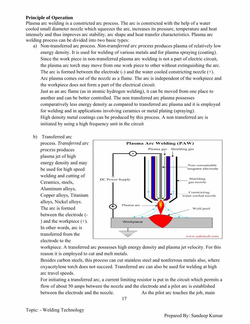
Principle of OperationPlasma arc welding is a constricted arc process. The arc is constricted with the help of a water cooled small diameter nozzle which squeezes the are, increases its pressure, temperature and heat intensely and thus improves arc stability, arc shape and heat transfer characteristics. Plasma arc welding process can be divided into two basic types:
a) Non-transferred arc process. Non-transferred arc process produces plasma of relatively low energy density. It is used for welding of various metals and for plasma spraying (coating). Since the work piece in non-transferred plasma arc welding is not a part of electric circuit, the plasma arc torch may move from one work piece to other without extinguishing the arc.The arc is formed between the electrode (-) and the water cooled constricting nozzle (+). Arc plasma comes out of the nozzle as a flame. The arc is independent of the workpiece and the workpiece does not form a part of the electrical circuit. Just as an arc flame (as in atomic hydrogen welding), it can be moved from one place to another and can be better controlled. The non transferred arc plasma possesses comparatively less energy density as compared to transferred arc plasma and it is employed for welding and in applications involving ceramics or metal plating (spraying). High density metal coatings can be produced by this process. A non transferred arc is initiated by using a high frequency unit in the circuit
b) Transferred arc process. Transferred arc process produces plasma jet of high energy density and may be used for high speed welding and cutting of Ceramics, steels, Aluminum alloys, Copper alloys, Titanium alloys, Nickel alloys. The arc is formed between the electrode (-) and the workpiece (+). In other words, arc is transferred from the electrode to the workpiece. A transferred arc possesses high energy density and plasma jet velocity. For this reason it is employed to cut and melt metals. Besides carbon steels, this process can cut stainless steel and nonferrous metals also, where oxyacetylene torch does not succeed. Transferred arc can also be used for welding at high arc travel speeds. For initiating a transferred arc, a current limiting resistor is put in the circuit which permits a flow of about 50 amps between the nozzle and the electrode and a pilot arc is established between the electrode and the nozzle. As the pilot arc touches the job, main

Topic: - Welding Technology Prepared By: Sandeep Kumar
18
current starts flowing between electrode and job, thus igniting the transferred arc. The pilot arc initiating unit gets disconnected and pilot arc extinguishes as soon as the arc between the electrode and the job is started. The temperature of a constricted plasma arc may be of the order of 8000-25000°C
Plasma Arc Equipment - A plasma arc welding system. The equipments needed in plasma arc welding along with their functions are as follows: 1. Power Supply. A direct current power source (generator or rectifier) having drooping characteristics and open circuit voltage of 70 volts or above is suitable for plasma arc welding. Rectifiers are generally preferred over DC generators.
Working with helium as an inert gas needs open circuit voltage above 70 volts. This higher voltage can be obtained by series operation of two power sources; or the arc can be initiated with argon at normal open circuit voltage and then helium can be switched on.
Typical welding parameters for plasma arc welding are as follows: Current 50 to 350 amps, voltage 27 to 31 volts, gas flow rates 2 to 40 liters/minute (lower range for orifice gas and higher range for outer shielding gas), DCSP in normally employed except for the welding of aluminium in which case water cooled copper anode and DCRP are preferred. 2. High frequency generator and current limiting resistors are used for arc ignition. Arc starting system may be separate or built in the system. 3. Plasma torch. It is either transferred arc or non transferred arc type. It is hand operated or mechanised. At present, almost all applications require automated system. The torch is water cooled to increase the life of the nozzle and the electrode. The size and the type of nozzle tip are selected depending upon the metal to be welded, weld shape and desired penetration height.. Shielding gases. Two inert gases or gas mixtures are employed. The orifice gas at lower pressure and flow rates forms the arc plasma. The pressure of the orifice gas is intentionally kept low to avoid weld metal turbulence, but this low pressure is not able to provide proper shielding of the weld pool. To have suitable shielding protection, same or another inert gas is sent through the outer shielding ring of the torch at comparatively higher flow rates. Most of the materials can be welded with argon, helium, argon + hydrogen and argon + helium, as inert gases or gas mixtures. Argon is very commonly used. Helium is preferred where a broad heat input pattern and flatter cover pass is desired. A mixture of argon and hydrogen supplies heat energy higher than when only argon is used and thus permits higher arc travel speeds and is preferred for welding some nickel base alloys and stainless steels.
For cutting purposes a mixture of argon and hydrogen (10-30%) or that of nitrogen and hydrogen may be used. Hydrogen, because of its dissociation into atomic form and thereafter recombination generates temperatures above those attained by using argon or helium alone. 5. Voltage control. Voltage control is required in contour welding. In normal key hole welding a variation in arc length up to 1.5 mm does not effect weld bead penetration or bead shape to any significant extent and thus a voltage control is not considered essential.6. Current and gas decay control. It is necessary to close the keyhole properly while terminating the weld in the structure.7. Fixture. It is required to avoid atmospheric contamination of the molten metal under bead.

Topic: - Welding Technology Prepared By: Sandeep Kumar
19
Base Metal Welded Base metals welded by Plasma arc welding are(i) Carbon and low alloy steels (ii) Stainless steels(iii) Copper alloys(iv) Nickel and cobalt base alloys(v) Titanium alloys(vi) Aluminium alloys.
Comparison Between Plasma Arc Welding and TIG Welding -
Plasma Arc Welding TIG welding1. It employs a constricted arc. 1. 1. It uses a non-constricted arc.
2. It uses two inert gases, one plasma gas and another inert gas to shield plasma and weld pool.
2. 2. It uses only one gas which forms plasma as well as shields the arc and molten weld pool.
3. To protect atmospheric contamination of underbead a set up as may be employed.
3. No such arrangement is employed
4. Electrode remains within the nozzle, therefore, chances of tungsten inclusion and electrode contamination are nil.
4. Appreciable chances of tungsten inclusion and electrode contamination are there if carelessly welded.
5. Improved input heat distribution in the job as compared to TIG welding.
6. By controlling arc current and orifice gas flow it is possible to have a greater control over penetration as compared to TIG welding.
7. Filler metal requirements are less as compared to TIG welding because lesser number of runs is needed to complete the weld.
8. It permits faster metal deposition rates and higher arc travel speeds as compared to TIG welding.
9. Plasma arc welding is less sensitive to joint mismatch and small variations in arc length as compared to TIG welding.
10. Total welding time required is less as compared to TIG welding.
Advantages Disadvantages and Applications of Plasma Arc Welding -AdvantagesSome of the advantages of plasma arc welding in addition to those mentioned under section 4.11.9 are listed below: 1. Stability of arc.2. Uniform penetration.3. Simplified fixtures.4. Rewelding of the root of the joint saved.5. It is possible to produce fully penetrated keyhole welds on pieces upto and about 6 mm thick with square butt joint. 6. Excellent weld quality.

Topic: - Welding Technology Prepared By: Sandeep Kumar
20
7. Plasma arc welding can produce radiographic quality welds at high speeds.8. It can weld steel pieces up to about one half inch thick; square butt joint in single run with no filler metal addition.
Disadvantages1. Infrared and ultraviolet radiations necessitate special protection devices.2. Welders need ear plugs because of unpleasant, disturbing and damaging noise.3. More chances of electrical hazards are associated with this process.4. The process is limited to metal thickness of 25 mm and lower for butt welds.5. Plasma arc welding process and equipment are more complicated and require greater knowledge on the part of the welder as compared to TIG welding.6. Inert gas consumption is high
ApplicationsPlasma arc welding finds applications as follows:1. Single runs autogenous and multi-run circumferential pipe welding.2. in tube mill applications.3. Welding cryogenic, aerospace and high temperature corrosion resistant alloys.4. Nuclear submarine pipe system (non-nuclear sections, sub assemblies).5. Welding steel rocket motor cases.6. Welding of stainless steel tubes (thickness 2.6 to 6.3 mm).7. Welding of carbon steel, stainless steel, nickel, copper, brass, monel, inconel, aluminium, titanium, etc.8. Welding titanium plates up to 8 mm thickness.9. Welding nickel and high nickel alloys.10. for melting, high melting point metals.11. Plasma torch can be applied to spraying, welding and cutting of difficult to cut metals and alloys
ElectrodesDepending upon the material of the electrode, it may melt and supply filler metal; if it is non-consumable, a separate filler addition generally becomes necessary.
The Composition of the core wire depends upon the metal to be welded. For example, to weld mild steel, core wire of similar composition will be prepared, in order to get a homogeneous welded joint. The size or diameter of the core wire will depend upon the amount of weld metal to be deposited and on the type of joint or the gap to be bridged between the two plates to be welded. Higher currents will be required to weld with bigger diameter electrodes.The length of the core wire is designed after considering rigidity, electrical resistance, the ease in welding and the diameter of the electrode. Generally thin and larger diameter electrodes are of shorter lengths and medium sized electrodes have bigger lengths. The reason is if thin electrodes are made longer they may bend and welding may not be carried out properly; and if bigger diameter electrodes are made long, their weight may increase too much to make welding operation inconvenient for the operator. In longer electrodes, electrical resistance and thus the heat generated in the electrode body increases, which may spoil the electrode covering. Diameter remaining same, an electrode of higher resistance material is normally made smaller in length.Non Consumable or Refractory Electrodes - They are made up of high welting, point materials like carbon (MP 6700°F), pure tungsten (MP 6150°F) or alloy tungsten. These electrodes do not melt away during welding. They maintain the arc which melts the base metal (as in TIG and
Topic: - Welding Technology Prepared By: Sandeep Kumar
21
carbon arc welding). Strictly speaking, these electrodes cannot be called nonconsumable.
The electrode length goes on decreasing with the passage of time, because of vaporization and oxidation of the electrode material during welding. In welding processes using refractory electrodes, filler metal addition mayor may not be needed, depending upon the plate thickness and the type of joint. First amongst the non-consumable electrodes are copper coated carbon or graphite electrodes. Copper coating increases the electrical conductivity or current conducting capacity of the electrodes. A comparison of carbon and graphite electrodes is given belowCarbon Electrodes1. Less expensive. 2. Carry less current.3. Long life.4. Arc control is comparatively difficult.5. Material is hard and brittle.6. Lesser electrical resistance.
Graphite Electrodes1. Comparatively costlier2. Carry larger currents as compared to carbon electrodes.3. Short life.4. Simpler arc control.5. Soft material.6. Higher electrical resistance
Carbon or graphite electrodes ranging from 2 mm to 15 mm are employed for welding purposes.Next amongst non-consumable electrodes are, those of pure tungsten, (1 or 2%) thoriated or (0.3-0.5%) zirconiated tungsten electrodes. Alloying pure tungsten increases emissivity, resistance to contamination, arc stability, and electrode life. In addition, arc initiation is easier, electrode tip remains cooler (as compared to pure tungsten electrode), electrode consumption is less and there is a gain in current carrying capacity. As compared to carbon electrodes, tungsten electrodes are much more expensive and alloy tungsten electrodes are still more costly. Tungsten/alloy tungsten electrodes ranging from 0.5 mm to 6 mm diameter are commonly available for welding purposes.
Consumables Electrodes - They are low melting point electrodes made up of different metals and their alloys. When the arc between the electrode and job is struck, the end of the electrode starts melting and transfers to the job in the form of droplets. The electrode itself adds filler metal. Droplets transferring (from electrode end and through arc) to the workpiece deposit there most of the heat generated as resistance heating in the electrode and of the arc.
Because of this reason a consumable electrode welding system possesses higher thermal efficiency (about 85%) as compared to that of a nonconsumable electrode welding arrangement (about 55%). Consumable electrodes may be of the following types.
Bare electrodesThey consist of a metal or alloy wire without any flux coating on them. Lightly coated electrodesElectrodes with a coating factor* approximately 1.25 are termed as lightly coated electrodes.Medium coated electrodes They are the electrodes with a coating factor

Topic: - Welding Technology Prepared By: Sandeep Kumar
22
about 1.45. Heavily coated electrodes The coating factor is between 1.6 and 2.2 for heavily coated electrodes. Example: Citofine (A.O.). As compared to lightly coated electrodes, heavily coated ones find applications in severe conditions; they produce deeper penetrations and weld metal of high quality. In heavily coated electrodes, the core wire melts before the flux coating, giving rise to a cavity, hence producing arc constriction and arc heat concentration on the workpiece
Because of unstable arc, irregular metal transfer and atmospheric contamination, bare electrodes do not produce sound and satisfactory welds but still they find application where weld strength is not a primary consideration and it is difficult to carry post cleaning of the joint. Covered Electrodes produce very well in heavy coated electrodes weld appearances, weld metal properties and defect free joints. Electrode Coating Ingredients and Their Functions - The covering/coating on the core wire consists of many materials which perform a number of functions as listed below: 1. Slag forming ingredients, like silicates of sodium *, potassium, magnesium, aluminium, iron oxide, china clay, mica etc., produce a slag which because of its light weight forms a layer on the molten metal and protects the same from atmospheric contamination.2. Gas shielding ingredients, like cellulose, wood, wood flour, starch, calcium carbonate etc., form a protective gas shield around the electrode end, arc and weld pool.3. Deoxidizing elements like ferro-manganese, and ferrosilicon, refine the molten metal.4. Arc stabilizing constituents like calcium carbonate, potassium silicate, titanate, magnesium silicates, etc. add to arc stability and ease of striking the same.
5. Alloying elements like ferro alloys of manganese, molybdenum etc. may be added to impart suitable properties and strength to the weld metal and to make good the loss of some of the elements, which vaporize while welding.
6. Iron powder in the coating improves arc behaviour, bead appearance; helps increase metal deposition rate and arc travel speed. In addition, the electrode covering may perform the following functions: 7. The covering improves penetration and surface finish.8. Core wire melts faster than the covering, thus forming a sleeve of the coating which constricts and produces an arc with high concentrated heat.9. It limits spatter, produces a quiet arc and easily removable slag.
10. With proper constituents, the slag may have quick freezing property and thus make overhead and vertical welding easy.11. Coating saves the welder from the radiations otherwise emitted from a bare electrode while the current flows through it during welding.12. Suitable coating will improve metal deposition rates.13. Proper coating ingredients produce weld metals resistant to hot and cold cracking. When a suitable thickness of the flux gets adhered to the core wire, the fixture is raised and the flux is allowed to dry. Welding Electrode Classification by American AWS-ASTM System -E XX XX or E 60 1 2E XXX XX or E 100 15 Letter E signifies that electrode is suitable for metal (electric) arc welding. XX/XXX First two or three digits indicate minimum tensile strength of weld metal in thousands of pounds per sq. inch, e.g. 60,000 and 100,000 lbs/sq. inch. Other values of XX and XXX are 45, 70, 80, 90

Topic: - Welding Technology Prepared By: Sandeep Kumar
23
and 120. Last but one digit indicates the welding position. It can be represented by numbers like 1, 2 and 3 which indicate that welding can be carried out in any position, flat and horizontal positions, and flat position respectively.
Last digit which may be 0, 1, 2, 3, 5 or 6 tells about power (2): supply, type of covering, type of arc, penetration characteristics, etc. (a) Electrode is meant for metal (electric) arc welding,(b) It possesses a minimum tensile strength of 60,000 pounds per Square inch,(c) It can weld satisfactorily in all positions,(d) Electrode covering has a high titania (rutile) content, is bounded with sodium silicate, can be operated on DCSP or AC, produces medium penetration, heavy slag, a convex weld bead appearance and a medium quality weld deposition.
Welding Electrode Classification by Indian (IS) System -L X X X X X1st 1st 2nd 3rd 4th 5th Example: E307411Various digits and letters indicate the following: 1st Letter -It can be E or R. E indicates that electrode is solid extruded and R means an electrode extruded with reinforcement. 1st Digit - It indicates the Glass of covering. It can be 1, 2, 3, 4, 5, 6 or 9 and has the meaning same as that of the first digit of British system, discussed earlier. 2nd Digit - It indicates the positions in which electrode can weld satisfactorily. Second digit may be 0, 1, 2, 3, 4, or 9. 0 and 1 signify that the electrode can be used for welding in all positions, and in flat, horizontal, overhead and vertical positions respectively. 4 indicates flat and horizontal fillet positions. 2, 3 and 9 have the same meaning as in British standard.
3rd Digit - It has the same meaning as that of the third digit of British standard, except that the open circuit voltage is 90 in place of 95 volts, and 50 instead of 45.4th and - They indicate range of tensile strength and value of minimum 5th Digit yield stress., e.g. 41 (fourth and fifth digits) and 51 mean that tensile strength ranges from 410-510 and 510-610 N/mm2 and minimum yield stress is 330 and 360 N/mm2 respectively. 6th Digit - It tells percentage elongation and impact value. Last - P indicates a deep penetration electrode, H hydrogen control.
Letter led electrode, and J, K, L indicate electrodes with iron powder coating and metal recovery 110-130%,130-150% and above 150%, respectively. Example: E 307411 means (a) It is a solid extruded electrode. (b) Its covering contains appreciable amount of titanium a fluid slag. (c) It is all position electrode, (d) It can be operated on DCRP, DCSP or AC with a power source having, open circuit voltage 50 volts, (e) Weld metal tensile strength ranges between 410 and 510 N/mm2 and minimum yield stress is 330 N/mm2. (10 N/mm2 = 1.02 kgf/mm2). (f) Minimum percentage elongation of weld metal (in tension) is 20% of 5.65 √S0 and impact value of weld metal at 27°C is 4.8 kgf m (or 47 J). Where S0 is the cross section area of the specimen being tested.

Topic: - Welding Technology Prepared By: Sandeep Kumar
24
RESISTANCE WELDING
Resistance Welding is a welding process, in which work pieces are welded due to a combination of a pressure applied to them and a localized heat generated by a high electric current flowing through the contact area of the weld. Resistance Welding Processes and Equipments - Resistance welding is a group of welding processes wherein coalescence is produced by the heat obtained from resistance of the work to the flow of electric current in a circuit of which the work is a part and by the applications of pressure. No filler metal is needed.
Heat produced by the current is sufficient for local melting of the work piece at the contact point and formation of small weld pool (”nugget”). The molten metal is then solidifies under a pressure and joins the pieces. Time of the process and values of the pressure and flowing current, required for formation of reliable joint, are determined by dimensions of the electrodes and the work piece metal type.
AC electric current (up to 100 000 A) is supplied through copper electrodes connected to the secondary coil of a welding transformer.
The following metals may be welded by Resistance Welding:
Low carbon steels - the widest application of Resistance Welding Aluminum alloys Medium carbon steels, high carbon steels and Alloy steels (may be welded, but the weld is
brittle)
Advantages of Resistance Welding -(i) Fast rate of production. (ii) No filler rod is needed. (iii) Semi automatic equipments. (iv) Less skilled workers can do the job. (v) Both similar and dissimilar metals can be welded. (vi) High reliability and reproducibility are obtained. (vii) More general elimination of warping or distortion of parts.Disadvantages of Resistance Welding -(i) The initial cost of equipment is high. (ii) Skilled persons are needed for the maintenance of equipment and its controls. (iii) In some materials, special surface preparation is required. (iv) Bigger job thicknesses cannot be welded.
Applications of Resistance Welding -Resistance welding is used for(i) Joining sheets, bars, rods and tubes. (ii) Making tubes and metal furniture. (iii) Welding aircraft and automobile parts. (iv) Making cutting tools.

Topic: - Welding Technology Prepared By: Sandeep Kumar
25
(v) Making fuel tanks of cars, tractors etc. (vi) Making wire fabric, grids, grills, mash weld, containers etc.
The most popular methods of Resistance Welding are:
Spot Welding (RSW) Seam Welding (RSEW) Flash Welding (FW) Resistance Butt Welding (UW)
Spot Welding (RSW)
Spot welding came into use in the period 1900-1905. It is now the most widely used of resistance welding processes. Spot welding is employed for joining sheet to sheet, sheets to rolled sections or extrusions, wire to wire, etc. Spot welding is used for joining relatively light gauge parts (up to about 3 mm thick) superimposed on one another (as a lap joint). DefinitionSpot welding is a resistance welding process in which overlapping sheets are joined by local fusion at one or more spots by the heat generated, by resistance to the flow of electric current through workpieces that are held together under force by two electrodes, one above and the other below the two overlapping sheets.
Spot Weldable
Metals -(i) Low carbon steel (mild steel). (ii) Hardenable steels, which, after getting spot welded are treated in an annealing furnace. (iii) High speed steel bits are spot welded to tool shanks for use in lathes, shapers, etc. The tool, after A. Unequal thickness; Band C Multiple thickness getting welded, is annealed before final hardening. (iv) Stainless steelsFerritic stainless steels behave very much as mild steel, however, the pressure should be kept a little longer after welding. Martensitic (cutlery and similar qualities) stainless steel can be treated as hardenable steel as it has pronounced air hardening qualities.
Non-ferrous Metals(i)Aluminium(ii) Aluminium Magnesium Alloys(iii) Aluminium Manganese Alloys(i), (ii) and (iii) may be spot welded satisfactorily. Oxide film on them is removed

Topic: - Welding Technology Prepared By: Sandeep Kumar
26
and a high capacity machine is used as aluminium is a good conductor.(iv) Copper. For welding copper upto 1.5 mm thick, hardfaced or pure tungsten (welding) electrodes are necessary. For bigger thicknesses spot welding is not preferred.Copper and aluminium and their alloys being very good conductors of heat and electricity are difficult metals from the resistance welding stand point as compared to mild steel.(v) Nickel, Nickel alloys and Monel Metal require machine capacity and settings rather similar to those employed for spot welding stainless steels.
Electrode Materials - Considering the above-mentioned requirements, the following materials are used for manufacturing spot (resistance) welding electrodes. (a) Group A 1. Copper 99%, Cadmium 1% alloy It has high strength and hardness coupled with high electrical and thermal conductivities. It is non-heat-treatable and is, therefore, hardened and strengthened by cold working. It is recommended for spot welding: (i) Low-carbon steel coated with tin, terne metal, chromium or zinc,(ii) Scaly hot-rolled low-carbon steel,(iii) Aluminium and Magnesium alloys.
2. Copper 99.2%, Chromium 0.8% alloyIt has high mechanical properties but lower thermal and electrical conductivities than Cu-Cd alloy. Optimum properties are developed by heat-treatment or by a combination of heat-treatment and cold work. It is used for spot welding. (i) Cold rolled low-carbon steels(ii) Hot rolled pickled low-carbon steels(iii) Nickel plated steel(iv)Stainless steel(v) Nickel alloys(vi)Copper-base alloys such as silicon bronze and nickel silver.
3. Beryllium 0.5%, Nickel 1%*, Cobalt 1%, and rest is copperIt is hardenable alloy with higher mechanical properties, but lower electrical and thermal conductivities than Cu-Cd or Cu-Cr alloys. It is preferred where pressures and workpiece resistance are high. It is used for spot welding (i) Thick sections of low-carbon steel(ii) Stainless steel(iii) Monel and Inconel. (b) Group-B 4. Refractory-Metal Compositions.These materials are employed where high heat, long weld time, inadequate cooling or high pressure would cause rapid deterioration of the copper-base alloys discussed above. A typical refractory-metal composition is given below:
42% Cu, 58% W (by volume): This is used for spot welding of stainless steel. When a copper alloy is being spot welded to steel, a group B electrode is used to contact the copper alloys and a group A electrode of type (1) or (2) is used to contact the steel. 5. Special alloy electrodesThey are made up of copper-zirconium and copper-cadmium zirconium.

Topic: - Welding Technology Prepared By: Sandeep Kumar
27
They find applications similar to alloy (1) but where resistance to softening of the electrode face is amust.
Resistance-Seam Welding (RSEW)Seam Welding is a Resistance Welding (RW) process of continuous joining of overlapping sheets by passing them between two rotating electrode wheels. Heat generated by the electric current flowing through the contact area and pressure provided by the wheels are sufficient to produce a leak-tight weld.
Resistance seam welding (RSEW) is a resistance welding process which produces coalescence at the faying surfaces the heat obtained from resistance to electric current through the work parts held together under pressure by electrodes.
The resulting weld is a series of overlapping resistance spot welds made progressively along a joint rotating the electrodes. When the spots are not overlapped enough to produce gaslight welds it is a variation known as roll resistance spot welding. This process differs from spot welding since the electrodes are wheels. Both the upper and lower electrode wheels are powered. Pressure is applied in the same manner as a press type welder. The wheels can be either in line with the throat of the machine or transverse. If they are in line it is normally called a longitudinal seam welding machine. Welding current is transferred through the bearing of the roller electrode wheels. Water cooling is not provided internally and therefore the weld area is flooded with cooling water to keep the electrode wheels cool.
In seam welding a rather complex control system is required. This involves the travel speed as well as the sequence of current flow to provide for overlapping welds. The welding speed, the spots per inch, and the timing schedule are dependent on each other. Welding schedules provide the pressure, the current, the speed, and the size of the electrode wheels.
This process is quite common for making flange welds, for making watertight joints for tanks, etc. Another variation is the so-called mash seam welding where the lap is fairly narrow and the electrode wheel is at least twice as wide as used for standard seam welding. The pressure is increased to approximately 300 times normal pressure. The final weld mash seam thickness is only 25% greater than the original single sheet.
Seam Welding is high speed and clean process, which is used when continuous tight weld is required (fuel tanks, drums, domestic radiators).

Topic: - Welding Technology Prepared By: Sandeep Kumar
28
Flash Welding (FW)
Flash Welding is a Resistance Welding (RW) process, in which ends of rods (tubes, sheets) are heated and fused by an arc struck between them and then forged(brought into a contact under a pressure) producing a weld.
The welded parts are held in electrode clamps, one of which is stationary and the second is movable.Flash Welding method permitts fast (about 1 min.) joining of large and complex parts.Welded part are often annealedfor improvement of Toughnesstoughness of the weld.Steels, Aluminum alloys, Copper alloys, Magnesium alloys, Copper alloys and Nickel alloysmay be welded by Flash Welding.Thick pipes, ends of band saws, frames, aircraft landing gears are produced by Flash Welding.
Resistance Butt Welding (UW)
Resistance Butt Welding is a Resistance Welding (RW) process, in which ends of wires or rods are held under a pressure and heated by an electric current passing through the contact area and producing a weld.
The process is similar to Flash Welding, however in Butt Welding pressure and electric current are applied simultaneously in contrast to Flash Welding where electriccurrent is followed by forging pressure application.
Butt welding is used for welding small parts. The process is highly productive and clean. In contrast to Flash Welding, Butt Welding provides joining with no loss of the welded materials.
Topic: - Welding Technology Prepared By: Sandeep Kumar
29
Thermo Chemical Welding ProcessesThermochemical welding processes involve Exothermic Reactions.Thermochemical welding processes discussed here are1. Thermit welding.2. Atomichydrogen welding.
THERMIT WELDINGdefinition- Thermit welding comprises a group of welding processes where in coalesence is produced by heating with superheated liquid metal and slag resulting from chemical reaction
between a metal oxide and, aluminium, with or without the application of pressure. The liquid metal acts as filler metal too.
Thermite welding (TW) (sometimes called thermit welding) is a process which joins metals by heating them with super heated liquid metal from a chemical reaction between a metal oxide and
aluminum or other reducing agent, with or without the application of pressure. Filler metal is obtained from the liquid metal.
b. The heat for welding is obtained from an exothermic reaction or chemical change between iron oxide and aluminum. This reaction is shown by the following formula:
8A1 + 3fe304 = 9FE + 4A1203 + Heat
The temperature resulting from this reaction is approximately 4500°F (2482°C).
c. The super heated steel is contained in a crucible located immediately above the weld joint. The exothermic reaction is relatively slow and requires 20 to 30 seconds, regardless of the amount of chemicals involved. The parts to be welded are aligned with a gap between them. The super heated steel runs into a mold which is built around the parts to be welded. Since it is almost twice as hot as the melting temperature of the base metal, melting occurs at the edges of the joint and alloys with the molten steel from the crucible. Normal heat losses cause the mass of molten metal to solidify, coalescence occurs, and the weld is completed. If the parts to be welded are large, preheating within the mold cavity may be necessary to bring the pats to welding temperature and to dry out the mold. If the parts are small, preheating is often eliminated. The thermit welding process is applied only in the automatic mode. Once the reaction is started, it continues until completion.
d. Themite welding utilizes gravity, which causes the molten metal to fill the cavity between the parts being welded. It is very similar to the foundry practice of pouring a casting. The difference is the extremely high temperature of the molten metal. The making of a thermit weld is shown in figure 6-12. When the filler metal has cooled, all unwanted excess metal may be removed by oxygen cutting, machining, or grinding. The surface of the completed weld is usually sufficiently smooth and contoured so that it does not require additional metal finishing

Topic: - Welding Technology Prepared By: Sandeep Kumar
30
thermite welding equipment
a. General. Thermite material is a mechanical mixture of metallic aluminum and processed iron oxide. Molten steel is produced by the thermite reaction in a magnesite-lined crucible. At the bottom of the crucible, a magnesite stone is burned, into which a magnesite stone thimble is fitted. This thimble provides a passage through which the molten steel is discharged into the mold. The hole through the thimble is plugged with a tapping pin, which is covered with a fire-resistant washer and refractory sand. The crucible is charged by placing the correct quantity of thoroughly mixed thermit material in it. In preparing the joint for thermite welding, the parts to be welded must be cleaned, alined, and held firmly in place. If necessary, metal is removed from the joint to permit a free flow of the thermite metal into the joint. A wax pattern is then made around the joint in the size and shape of the intended weld. A mold made of refractory sand is built around the wax pattern and joint to hold the molten metal after it is poured. The sand mold is then heated to melt out the wax and dry the mold. The mold should be properly vented to permit the escape of gases and to allow the proper distribution of the thermite metal at the joint. A thermite welding crucible and mold is shown in figure 5-41.

Topic: - Welding Technology Prepared By: Sandeep Kumar
31
b.
Advantages and Disadvantages of Thermit Welding -ADVANTAGES1. The heat necessary for welding is obtained from a chemical reaction and thus no costly power supply is required. Therefore broken parts (rails etc.) can be welded on the site itself.3. For welding large fractured crankshafts. 4. For welding broken frames of machines. 5. For building up worn wobblers.6. For welding sections of castings where size prevents there being cast in one piece.7. For replacing broken teeth on large gears.8. Forgings and flame cut sections may be welded together to make huge parts.9. For welding new necks to rolling mill rolls and pinions.10. For welding cables for electrical conductors.11. For end welding of reinforcing bars to be used in concrete (building) construction.Limitations1. Thermit welding is applicable only to ferrous metal parts of heavy sections, i.e., mill housings and heavy rail sections.2. The process is uneconomical if used to weld cheap metals or light parts.Uses and Applications of Thermit Welding - Thermit welding is used chiefly in the repair or assembly of large1. For repairing fractured rails (railway tracks).2. For buttwelding pipes end to end.
The atomic hydrogen thus formed is unstable and has a tendency to revert back to molecular state. This recombination takes place as the atomic hydrogen reaches a comparatively cooler region just outside the arc boundary or as the atomic hydrogen touches relatively cold workpiece t6 be welded.The recombination is an exothermic reaction which liberates large amount of heat, (temperature being approximately 3730ºC). This heat combined with that of the arc

Topic: - Welding Technology Prepared By: Sandeep Kumar
32
(produces temperatures higher than those in oxyacetylene or metallic arc welding processes and) is utilized for welding purposes. Moreover, owing to very high heat conductivity of hydrogen at elevated temperatures, the heat is delivered to workpieces at very fast rates
ATOMIC HYDROGEN WELDING
Definition and Principle of Operations - It is a welding process wherein coalescence (fusion) is produced by heating the job with an electric arc maintained between two tungsten electrodes in an atmosphere of hydrogen, which also acts as a shielding gas. Filler rod and pressure mayor may not be applied depending upon job conditions.
PRINCIPLEAtomic hydrogen welding possesses the features of both arc and flame welding processes. The job does not form a part of the electrical circuit. The arc remains only between two tungsten electrodes and the edge of the arc flame is used to weld the work pieces.
It is the combined energy of the arc and a chemical reaction, which is utilized for welding. The arc supplies energy for a chemical reaction to take place which is described below.The molecular hydrogen passes through the electric arc and it dissociates into atomic hydrogen by absorbing the energy supplied by the electric arc.Atomic Hydrogen Welding Equipments -(a) Welding torch with tungsten electrodes and cable ,(b) Hydrogen gas supply,(c) AC power source (a transformer with an open circuit voltage of about 300 volts).
(if DC is used, an unequal amount of heal is available on the two electrodes, arc cleaning action is not proper, life of the two electrodes is not same, and frequent adjustment of the electrodes is necessary to maintain a stable arc.)Advantages and Disadvantages of Atomic Hydrogen Welding -ADVANTAGES1. Due to high concentration of heat, welding can be carried out at fast rates (especially when filler metal is not needed) and with less distortion of the workpiece.2. The job does not form a part of the electrical circuit. The arc remains between two tungsten electrodes and can be moved to other places easily without getting extinguished.

Topic: - Welding Technology Prepared By: Sandeep Kumar
33
3. No flux or separate shielding gas is used; hydrogen itself acts as a shielding gas and avoids weld metal oxidation.4. Welding of thin materials is also possible which otherwise may not be successfully carried out by metallic arc welding.5. The process can be used to weld materials of specific chemical compositions for which coated electrodes may not be available.6. Uniform, dense, strong and ductile welds can be producedDISADVANTAGES1. Welding speed is less as compared to that of metallic arc or MIG welding.2. The process becomes uneconomical for certain applications because of higher operating cost as compared to that of other welding processes.3. The process cannot be used for depositing large quantities of metals.Applications of Atomic Hydrogen Welding -1. The process can be used for the welding of most of the metals and alloys like plain carbon steel, alloy steel, stainless steel, aluminium, copper, nickel and their alloys. 2. for surfacing dies and tools
RADIANT ENERGY WELDING PROCESS- Radiant energy processes focus an energy beam on the work piece. The heat is generated only when the energy beam strikes the workpiece. Radiant energy processes are 1. Electron Beam Welding. 2. Laser Beam Welding
ELECTRON BEAM WELDING
hough the development of the electron beam has evolved over the past three hundred years or so, the use of the electron beam in welding industry is quite new. The need for electron beam welding developed after World War II, when it was required to obtain ultrahigh purity welds in reactive and refractory metals used in the atomic energy and rocketry field. Electron beam welding is now used to weld titanium, tungsten, molybdenum, stainless steel, aluminium and many of the more refractory metals. In electron beam welding, the heat to melt the metals is generated not by a flame or arc but by a stream of highly accelerated electrons. The energy of electrons does not appear as heat, until the electrons hit the workpiece
Electron Beam Welding Definition and Principle of Operations - Electron beam welding is defined as a fusion welding process wherein coalescence is produced by the heat obtained from a concentrated beam composed primarily of high velocity electrons. As the high velocity electrons strike the surfaces to be joined, their kinetic energy changes to thermal energy thereby causing the workpiece metal to melt and fuse.
Welding operation may be carried out in (i) Hard vacuum,(ii) Partial vacuum, and(iii) Atmosphere (i) Hard vacuum. When welding is to be carried out in hard or high vacuum, both the electron beam gun and the workpiece are enclosed in the same vacuum chamber. The pressure in the chamber
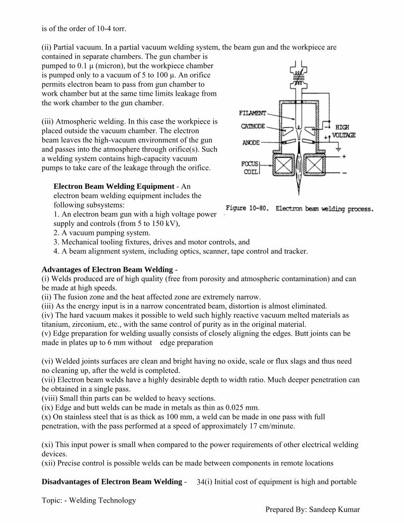
Topic: - Welding Technology Prepared By: Sandeep Kumar
34
is of the order of 10-4 torr.
(ii) Partial vacuum. In a partial vacuum welding system, the beam gun and the workpiece are contained in separate chambers. The gun chamber is pumped to 0.1 μ (micron), but the workpiece chamber is pumped only to a vacuum of 5 to 100 μ. An orifice permits electron beam to pass from gun chamber to work chamber but at the same time limits leakage from the work chamber to the gun chamber.
(iii) Atmospheric welding. In this case the workpiece is placed outside the vacuum chamber. The electron beam leaves the high-vacuum environment of the gun and passes into the atmosphere through orifice(s). Such a welding system contains high-capacity vacuum pumps to take care of the leakage through the orifice.
Electron Beam Welding Equipment - An electron beam welding equipment includes the following subsystems: 1. An electron beam gun with a high voltage power supply and controls (from 5 to 150 kV),2. A vacuum pumping system.3. Mechanical tooling fixtures, drives and motor controls, and4. A beam alignment system, including optics, scanner, tape control and tracker.
Advantages of Electron Beam Welding -(i) Welds produced are of high quality (free from porosity and atmospheric contamination) and can be made at high speeds. (ii) The fusion zone and the heat affected zone are extremely narrow. (iii) As the energy input is in a narrow concentrated beam, distortion is almost eliminated. (iv) The hard vacuum makes it possible to weld such highly reactive vacuum melted materials as titanium, zirconium, etc., with the same control of purity as in the original material. (v) Edge preparation for welding usually consists of closely aligning the edges. Butt joints can be made in plates up to 6 mm without edge preparation
(vi) Welded joints surfaces are clean and bright having no oxide, scale or flux slags and thus need no cleaning up, after the weld is completed. (vii) Electron beam welds have a highly desirable depth to width ratio. Much deeper penetration can be obtained in a single pass. (viii) Small thin parts can be welded to heavy sections. (ix) Edge and butt welds can be made in metals as thin as 0.025 mm. (x) On stainless steel that is as thick as 100 mm, a weld can be made in one pass with full penetration, with the pass performed at a speed of approximately 17 cm/minute.
(xi) This input power is small when compared to the power requirements of other electrical welding devices. (xii) Precise control is possible welds can be made between components in remote locations
Disadvantages of Electron Beam Welding - (i) Initial cost of equipment is high and portable

Topic: - Welding Technology Prepared By: Sandeep Kumar
35
equipment is rare. (ii) Work is to be manipulated through vacuum seals. (iii) Time and equipment is required to create vacuum everytime a new job is to be welded. (iv) Precautions are needed to prevent damage from X-rays. (v) Electron beam travels on a line of sight, therefore, obstructed joints cannot be welded.(vi) Because of complexity of circuitry, very competent persons are required. (vii) Workpiece size is limited by the work chamber dimensions. Moreover, the workpiece being in an evacuated chamber becomes inaccessible and thus need to be manipulated by some special device
Applications of Electron Beam Welding -(i) For welding reactive'" and refractory'" metals used in the atomic energy and rocketry fields. (ii) For welding other common similar'" * and dissimilar metal combinations [e.g. Invar (64Fe -36Ni) and (12Mn -18 Cu -10Ni); stainless steel and Inconel, titanium, and copper, etc.]. (iii) For welding automobile, airplane, aerospace, farm and other types of equipment, where especially low distortion is desired. (iv) Since arc length may be varied from very short to very long without changing the quality of welds, welds can be made even at those points that are virtually inaccessible for other welding processes
(v) Recently developed machines can make two parallel beads simultaneously with one gun and find applications in the mass production of type writer carriages. (vi) Electron beam welding is very suitable where high quality, large scale, automatic welding operations are required or where other welding processes will not produce the desired results. (vii) Electron beam welding can do the same jobs as TIG and plasma welding; in some respects it is better.(viii) Materials ranging from thin foils to 50 mm in thickness can be joined by electron beam welding.
ix) Electron beam welding is used to assemble conventional production parts such as cams, gear clusters and driven shafts.
LASER BEAM WELDING
Definition and Concept - Laser beam welding is defined as a welding process where in coalescence is produced by the heat obtained from the application of a concentrated coherent light beam impinging upon the surfaces to be joined. All light consists of waves. In common light, these waves are incoherent and of varied lengths and frequencies that shoot off in numerous directions. The laser beam, on the other hand, is a coherent light i.e., the waves are identical and parallel. The laser is a device for concentrating light waves into narrowly defined highly intense beam that can impart tremendous energy on a small area to produce fusion for welding purposes.
Laser Beam Welding Principle and Theory of Operations -Laser welding system consists of (a) A man made cylindrical by crystal. Ruby is aluminium oxide with chromium dispersed throughout it, forming about 1/2000 of the crystal, which is less than a natural ruby contains. The ends of the crystal are silvered to form mirrors internally, while one end has a tiny hole in the silver layer, through which the laser beam emerges. (b) Around the outside of the crystal is placed

Topic: - Welding Technology Prepared By: Sandeep Kumar
36
flash tube containing inert gas xenon. The flash tube is designed for operation of a rate of thousands of flashes per second. Flash tube converts electrical energy into light energy. (c) The capacitor bank (storage) stores electrical energy. It is charged by a high voltage power supply. It energises the flash tube by an appropriate triggering system.
When subjected to electrical discharge from the capacitors, xenon transforms a high proportion of the electrical energy into white light flashes. The flash has a duration of about 1/1000 second. As the ruby is exposed to the intense light flashes, the chromium atoms of the crystal are excited and pumped to a high energy level. These chromium atoms immediately drop to an intermediate energy level with the evolution of heat, and eventually drop back to their original state with the evolution of a discrete quantity of radiation in the form of red fluorescent light. As the red light emitted by one excited atom hits another excited atom, the second atom gives off red light which is in phase with the colliding red light wave. In other words, the red light from the first atom is amplified because more red light exactly like it is produced.
The effect is enhanced because the parallel ends of ruby rod are mirrored so that the red light that is produced reflects back and forth along the length of the crystal. The chain reaction collisions between waves of fluorescent red light and chromium atoms become so numerous that finally, the total energy bursts over a threshold and escapes from the small hole in the mirror at one end of the ruby crystal as the laser beam. This narrow laser beam is focused by an optical focusing lens to produce a small intense spot of laser (light) on the job. Optical energy as it impacts the workpiece is converted into heat energy. The temperatures generated can be made sufficient to melt (and vaporize) the materials to be welded or cut. Since most of the power output of a laser source is lost as heat, cooling system is used to carry away the same. Both gas and liquid cooling is used, the latter being more common.
The laser welding machine has an optical reflective cavity which reflects and focuses high-intensity radiation from the flash lamps on to the ruby (crystal) rod. There are two techniques for laser welding. One is to move the workpiece so fast that a complete joint passes by and is welded by one burst. The other, and more common method, is to fuse a series of spots, commonly overlapping. In laser welding, a minute puddle is melted and frozen in a matter of microseconds. Since this time is very short, no chemical reaction between the molten metal and atmosphere takes place and

Topic: - Welding Technology Prepared By: Sandeep Kumar
37
hence in laser welding no protection (shielding etc.) is needed against atmospheric contamination.
Advantages of Laser Beam Welding -(i) Welds can be made inside transparent glass or plastic housings. (ii) A wide variety of materials can be welded, including some formerly considered as unweldable combinations.(iii) As no electrode is used, electrode contamination or high electric current effects are eliminated. (iv) Areas not readily accessible can also be welded. (v) It permits welding of small, closely spaced components with welds as small as a few microns in diameter. (vi) Surface contaminants such as oxides and organic materials make little, if any, difference in the quality of the weld. (vii) Unlike electron beam welding it operates in air, no vacuum is required. (viii) Laser beam being highly concentrated and narrowly defined produces narrow size of the heat affected zone.
(ix) Because of its excellent control of heat input, the laser can fuse metal next to glass or even Weld near varnished coated wires without damaging the insulating properties of the varnish. (x) It is possible to weld heat treated alloys without affecting their heat-treated condition. (xi) In laser welding, laser beam's concentrated energy can be precisely controlled. Laser light is not only intense, it can also be readily focused without loss of intensity. (xii) For laser welding, mechanical contact of any kind with the job is not required; moreover, the material being welded need not be a conductor of electricity. (xiii) Because it is light, it can be focused to microscopic dimensions and directed with great accuracy. (xiv) Because it is light, it is clean no vaporized metal or electrodes dirty up the delicate assemblies
Disadvantages of Laser Beam Welding -(i) The major drawback to laser beam welds is the slow welding speeds (25 to 250 mm/min.) resulting from the pulse rates and puddle sizes at the fusion point. (ii) Laser welding is limited to depths of approximately 1.5 mm and additional energy only tends to create gas voids and undercuts in the work. (iii) Materials such as magnesium tend to vaporize and produce severe surface voids.
Applications of Laser Beam Welding -(i) Laser is a high energy light beam that can both weld and cut the metals. (ii) For connecting leads on small electronic components and in integrated circuitry in the electronic industry. (iii) To weld lead wires having polyurethane insulation without removing the insulation. The laser evaporates the insulation and completes the weld. (iv) To join hard high melting point metal alloys. (v) In space and aircraft industry for welding light gauge materials. (vi) Laser process can join dissimilar metals and other difficult to weld metals such as copper, nickel, aluminium, stainless steel, tungsten, columbium, titanium, zirconium, tantalum, kovar etc. (vii) Laser can weld wire-to-wire, sheet-to-sheet, wire-to-sheet, tube to-sheet and small-diameter stud welds.(viii) Laser beam is used for microwelding purposes. It is particularly suitable for the welding of miniaturized and microminiaturized components

Topic: - Welding Technology Prepared By: Sandeep Kumar
38
Solid State Welding Processes
A solid state welding process produces coalescence at temperatures essentially below the melting point of the base materials being joined, without the addition of a filler metal. Pressure is always applied.
The following solid state welding processes will be discussed in this chapter: 1. Cold welding2. Diffusion (bonding) welding3. Ultrasonic welding4. Explosive welding5. Friction welding and Inertia welding6. Forge welding.
Friction welding
Friction welding (FW) is a class of solid-state welding processes that generates heat through mechanical friction between a moving workpiece and a stationary component, with the addition of a lateral force called "upset" to plastically displace and fuse the materials. Technically, because no melt occurs, friction welding is not actually a welding process in the traditional sense, but a forgingtechnique. However, due to the similarities between these techniques and traditional welding, the term has become common. Friction welding is used with metals and thermoplastics in a wide variety of aviation and automotive applications.
Friction welding is a solid state welding process which produces coalescence of materials by the heat obtained from mechanically-induced sliding motion between rubbing surfaces. The work parts are held together under pressure. This process usually involves the rotating of one part against another to generate frictional heat at the junction. When a suitable high temperature has keen reached, rotational notion ceases. Additional pressure is applied and coalescence occurs.
(2) There are two variations of the friction welding process. They are described below.
(a) In the original process, one part is held stationary and the other part is rotated by a motor which maintains an essentially constant rotational speed. The two parts are brought in contact under pressure for a specified period of time with a specific pressure. Rotating power is disengaged from the rotating piece and the

Topic: - Welding Technology Prepared By: Sandeep Kumar
39
pressure is increased. When the rotating piece stops, the weld is completed. This process can be accurately controlled when speed, pressure, and time are closely regulated.
(b) The other variation is inertia welding. A flywheel is revolved by a motor until a preset speed is reached. It, in turn, rotates one of the pieces to be welded. The motor is disengaged from the flywheel and the other part to be welded is brought in contact under pressure with the rotating piece. During the predetermined time during which the rotational speed of the part is reduced, the flywheel is brought to an immediate stop. Additional pressure is provided to complete the weld.
(c) Both methods utilize frictional heat and produce welds of similar quality. Slightly better control is claimed with the original process. The two methods are similar, offer the same welding advantages, and are shown by figure 10-79.
The Friction Welding Process
1. Initial Situation:
Both workpieces are firmly clamped into the machine; one workpiece is rotated.
2. Heat Build-up:
The two workpieces are pressed together with a defined force; the rotation and contact force generate friction which causes the weld surfaces to heat up.
3. Welding:
At a defined moment in time, the rotating workpiece is braked and the contact pressure is increased. This creates the friction-welded joint
Materials Welded by Friction and Inertia Welding - Materials that can be friction/inertia welded are listed below: (i)Aluminium and its alloys (ii) Nickel alloys(iii) Brass and bronze(iv) Alloy steels(v) Magnesium alloys(vi) Carbon steels(vii) Stainless steel(viii) Tool steel(ix) Tantalum(x) Titanium alloys
(xi) Tungsten(xii) Zirconium alloys(xiii) Alloy steel to carbon steel (xiv) Copper to carbon steels(xv) Superalloys to carbon steels (xvi) Stainless steel to carbon steels

Topic: - Welding Technology Prepared By: Sandeep Kumar
40
(xvii) Sintered steels to carbon steels(xviii) Aluminium to stainless steels(xix) Copper to aluminium, etc.
In general, all forgeable materials which are not good dry bearing materials, can be easily welded. Cast iron in any form is not weldable because the free graphite acts as lubricant and limits frictional heating
Advantages and Disadvantages of Friction OR Inertia Welding -(i) Simplicity of operation.(ii) Low power requirements. (iii) Once the welding parameters for a job have been determined, the welding takes only a few seconds.(iv) Surface impurities and oxide films are broken up and thrown off during the friction heating process. (v) As compared to conventional flash or resistance butt welding, friction/inertia welding produces improved welds at higher speed and lower cost, less electric current is required, and costly copper fixtures to hold components are eliminated.
(vi) Heat is localized at the weld and is quickly dissipated so that there is only a slight effect on the parts joined. The heat affected zone adjacent to the weld is confined to a narrow band and therefore does not affect the temper of the surrounding area.The weld may not have to be heattreated.(vii) With inertia/friction welding there is less shortening of the component, as compared to that in flash or butt welding.(viii) Repeatability is reported as excellent, and several jobs have been fully automated.(ix) There is no flux, gas, filler metal or slag present to cause imperfections in welds. Also no smoke, fumes or spatter are produced.
Disvantages of Friction / Inertia Weding(i) The use of this process is restricted to flat and angular butt welds, where one part is normal to the other part.(ii) So far the process has been applied only to the joining of small pieces in the form of bar stock.(iii) Sometimes, quite a heavy flash is forced out in all inertia and friction welds.(iv) If tubing is welded, flash may have to be removed from inside the joint.(v) Flash from medium and high carbon steels being hard, must either be removed while it is hot or annealed before it is machined.(vi) Thrust pressures in inertia welding will range from 700 to 2800 kg/cm2, which requires a heavy rigid machine
Applications of Friction OR Inertia Welding -(i) Friction/inertia welding is finding varied applications for joining steels, super alloys, non ferrous metals and combinations of metals. (ii) It frequently replaces brazing and (metallic) are, electron beam, pressure, flash or resistance butt welding.(iii) Among its varied applications are:Production of steering shafts and worm gears, control shafts, axle shafts, engine valves, transmission shafts etc., for automobile industry.
Topic: - Welding Technology Prepared By: Sandeep Kumar
41
Production of bimetallic shafts, joining of superalloy turbine wheels to steels shafts, joining of thin walled containers to bases etc. Production of cutting tools like drills, taps, reamers and some of the shanked milling cutters where HSS cutting body is welded to carbon steel shanksManufacture of aluminium steel transition joints, copper to-aluminium transition pieces for electrical and refrigeration industry (Dissimilar metal welding). Welding together relatively simple forgings to make complex shapes. Fabrication of axle cases where a forging or axle spindle is welded to tubular banjo or beam (Transportation Industry).
Production of pump shafts and; control valve shafts, involving joints between plain carbon and corrosion resistant alloy steel (Oil and Gas Industries). Joining together dissimilar steel in the manufacture of bimetal fasteners that are used to support insulation covers for use in nuclear plant construction
http://www.welding-technology-machines.info/physics-of-welding/arc-stability.htmArc Stability - Arc is said to be stable if it is uniform and steady. A stable arc will produce good weld bead and a defect free weld nugget. Defects commonly introduced by unstable arc are slag entrapment, porosity, blow holes and lack of proper fusion. The stability of a welding arc is governed by so many factors, a few, as mentioned below: (a) Suitable matching of arc and power source characteristics. A little variation in arc length, i.e., arc voltage should not extinguish the arc.(b) Continuous and proper emission of electrons from the electrode (say cathode) and thermal ionization in the arc column. Emissivity of pure tungsten cathode is improved by making it thoriated or Zirconiated. (c) Position and movements of cathode and anode spots.(d) Arc length and arc current(e) Electrode tip geometry in TIG welding. (f) In AC welding;(i) Steadiness of current as regards its magnitude and wave shape.(ii) Use of surge injection or high frequency units in TIG welding.(iii) Use of arc stabilizing materials in the coating mixture of flux covered electrodes.(g) Conditions promoting Arc Blow. (h) Presence of dampness, oil, grease, etc. on the surface of workpiece. (i) Limited practice on the part of the welderArc Blow - The unwanted deflection or the wandering of a welding arc from its intended path is termed as arc blow or arc bow. Arc blow is the result of magnetic disturbances which unbalance the symmetry of the self induced magnetic field around the electrode, arc and workpiece. Under arc blow, an arc may distort, deflect or rotate. Arc blow becomes severe when welding is carried out in confined spaces and corners on heavy metal plates, using a DC power source. AC arcs are less susceptible to arc blow than DC arcs; because the alternating current reverses direction which in turn reverses the magnetic fieldThe magnetic field builds up, collapses and rebuilds as current reverses from positive to negative. This phenomenon does not permit the magnetic field strength to build to a value so as to cause arc blow. On the other hand in DC welding, the magnetic field set up in the workpiece (adjacent to the arc) continuously builds up and the arc blow occurs
Types of Arc Blow - Depending upon the factors discussed above, the arc may have, (a) a forward blow at the starting end of a weld and a backward blow at the finishing end of a weld,

Topic: - Welding Technology Prepared By: Sandeep Kumar
42
(b) a sideward deflection, (c) in addition to deflection arc may (sometimes) rotate also.
Mechanism of Arc Blow -(a) Forward and backward arc blowThe workpiece, electrode and arc positions. It also depicts flux lines of the magnetic field set up in the workpiece adjacent to arc due to the flow of current through the arc. Magnetic flux lines gel crowded near the starting and finishing end of the workpiece because they find an easy path through the workpiece than air.
The arc seeks the path of least resistance and deflects towards the weak flux side, which explains the cause of forward arc blow at the starting end and backward arc blow at the finishing end of the weld bead in a workpiece
(b) Sideward arc blowThe position of the workpiece earth clamp, electrode, arc and weld bead deflected from its intended path. As the arc comes near the earth clamp it deflects sidewardly in a direction away from the clamp, perhaps because of the magnetic flux created in the workpiece by the earth clamp (i.e., ground). This magnetic flux is produced by the flow of current from clamp to workpiece. It is also noted that as the arc crosses the earth connection, it has a tendency to come to the original line of travel.
Arc rotationThe arc deflection and rotation under arc blow. Arc rotation indicates that under certain conditions of arc blow, perhaps arc experiences magnetic field lines parallel to the arc axis.
Metal Transfer - When an electric arc is struck between the job and the consumable electrode, the arcing end of the electrode starts melting, takes approximately a spherical shape, hangs towards the job, and ultimately drops down on the same, either with a free flight through the arc or by short circuiting the job
. The size of the droplet and the metal (drop) transfer rate affects weld bead geometry, weld metal microstructures and the strength of the welded joint. Metal transfer has also got a significant effect upon the stability of arc discharge, ability to carry out welding in different positions (vertical, overhead, etc.) and the amount of spatter Control of metal transfer through different factors affecting it can increase the efficiency of a welding process. A correct understanding of metal transfer phenomena will develop improved welding techniques. In order to study mode and mechanism of metal transfer, research work started as early as 1928. Since then considerable work has been done and published, but even today the phenomenon is not very clear. Metal transfer is a complicated phenomenon as it involves so many factors and

Topic: - Welding Technology Prepared By: Sandeep Kumar
43
moreover is dynamic in nature.
In MIG welding, metal transfer is clearly visible and has been studied with the help of high speed movie cameras (3000--7000 frames/sec.). In flux shielded metal arc welding, a movie camera does not help much because arc and metal transfer are not clear because of fumes and slag particles. Similarly in submerged arc welding, the arc remains hidden under flux and thus metal transfer cannot be studied by ordinary camera. In both these processes however X-rays have been used to study metal transfer.
Short Circuiting OR Dip Metal Transfer - In short-circuiting type of metal transfer, the arcing end of the electrode starts melting, develops to a spherical shape; makes contact with the molten pool in the base metal and gets detached from the electrode. When the hanging drop touches the base metal, the circuit is shorted and the arc extinguishes. The moment the drop is detached from the electrode, the, circuit once again opens and arc gets reignited. The short circuiting frequency is mainly dependent upon electrode wire diameter and arc voltage (or arc length). With other parameters constant, short circuit frequency (i.e., number of short circuits/sec) increases as the wire diameter decreases.
There is a critical voltage at which the short circuit frequency is maximum, and the same decreases if the volute is increased or decreased. Normal short-circuiting frequency ranges from 20 to 200 per second
In short-circuiting transfer, while welding steel in CO2 atmosphere, the critical value of arc voltage is about 20 volts and maximum short circuiting frequency ranges from 75 to 150 with 1.5 mm and 0.75 mm diameter of electrode wires. Figure shows oscillogram of arc voltage and current along with various steps in which short circuiting metal transfer takes place.
During this period A to B, the drop grows, hangs and thus the arc voltage decreases. At point B short circuit occurs, arc extinguishes and the voltage drops down. Short circuit remains between the period from C to E, during which current increases because of reduced resistance between electrode and workpiece. There should be a sufficient increase in current so that neck does not freeze. For this reason a welding power source with nearly flat characteristics is recommended. Besides other forces aiding drop detachment, electromagnetic pinch effect plays most important part
The pinch effect strengthens as the current increases during shorting, neck formation quickens and ultimately at point E drop gets detached from the electrode. At this stage arc reignites and arc voltage shoots to normal value. At point F once again the drop formation starts, drop grows, hangs, thus arc resistance and arc voltage start reducing. Short circuit transfer needs less arc currents (average 125 amps. for approximately 0.9 mm wire diameter) as compared to spray transfer (average 200 amps. for approximately 0.9 mm wire diameter). Short circuit transfer is generally recommended on thinner sheets, of course thicker gauges can also be welded using large wire diameter (1.5 mm or around).
This mode of transfer is suitable especially when welding intricate shapes and in positions other than flat. Though this type of transfer is preferred for shallow penetrations, if desired, penetration can be increased by using bigger diameter wires and carbon dioxide as the shielding gas. Short circuit mode of metal transfer has been successfully employed for the welding of mild steel, stainless steel and other alloy steels.In addition to those mentioned above, another type of metal transfer known as "Repelled type" has

Topic: - Welding Technology Prepared By: Sandeep Kumar
44
been observed in MIG welding when using (a) CO2 as a shielding gas
(b) other shielding gases and DCSP. As shown in Fig the droplet appears to be repelled towards the side of the electrode. Gradually neck formation takes place and the drop separates. The detached drop during transfer may fall freely through the arc or short-circuit the electrode and the job. The repelled nature of the droplet may be due to high velocity gas jets striking the workpiece and getting back.
Pulsed Transfer (Pulsed Arc Welding) - Pulsed-arc welding is a controlled method of spray transfer welding requiring a more sophisticated power source, whereas the types of transfer described previously can be obtained with standard power sources and wire feed units. In spray transfer, droplets of metal are projected from the wire tip across the arc gap to the molten pool at a constant current. In dip transfer, metal is transferred to the molten pool somewhat irregularly during the periods of short circuiting. Pulsed arc welding enables droplets to be projected across the arc gap at a regular frequency, using pulses of current in the spray transfer range supplied from a special power source
Transfer of metal from the wire tip to the molten pool occurs only at the period of pulse or peak current. During the intervals between pulses, a low 'background' current maintains the arc to keep the wire tip molten but no metal is transferred. Pulsed transfer means that the weld metal is projected across the gap at high current, but the mean welding current remains relatively low. The operator can vary the pulse height and the background current to obtain full control of both the heat input and the amount of metal deposited; however, in many modern power sources the pulse procedure is preset by the manufacturer to simplify use. Pulsed arc transfer can be used on mild and low-alloy steels, stainless steel and is particularly useful with aluminum and its alloys on light to medium plate sections as dip transfer cannot be used on these alloys
Metallurgical Effects of Welding - Welding operations give rise to many metallurgical effects: 1. Weld metal is essentially a small casting with the inherent defects and characteristics of a casting.An appreciation of these characteristics can be easily attained by a study of the mechanism of solidification of metals and alloys. 2. Absorption of gases by weld metal and gas reactions is important in controlling the porosity of a weld, e.g., hydrogen in aluminium. Gas such as hydrogen is more easily dissolved in the molten metal at high temperature and may subsequently be trapped in the solid metal if cooling is rapid.The gas may either be retained in the microstructure or may form bubbles which can become trapped as porosity in the fast freezing metal. Gas metal reaction may take one of the two forms: physical (endothermic) solution, or exothermic reaction to form a stable chemical compound.
Endothermic solution does not exhibit fusion, but can result in porosity, either due to supersaturation of the weld pool with a particular gas or by reaction between two gases. Sometimes it may result in the embrittlement of HAZ also. 3. Slag inclusions are frequently trapped in fusion welds due to joint or bead contour and there is difficulty of removing or melting the slag in subsequent runs.4. Hot cracking of welds. Under constrained welding conditions, the contractional strains, sometimes, cause intercrystalline cracks in hot welds, the fractured surface being tinted with oxidation film. Hot cracking of welds occurs at elevated temperature. This may be attributed directly to the low ductility of the base metal at temperatures not too far below melting.High arc welding currents cause large columnar crystals to form with definite planes of weakness at the throat of the weld. Austenitic steels, (e.g. 25 Cr, 20 Ni) which normally solidify with large

Topic: - Welding Technology Prepared By: Sandeep Kumar
45
columnar crystals are prone to this difficulty. 5. Heat affected zone. Structural changes in H-A-Z.
Weld Metal Solidification - The solidification of metals is usually considered to be a nucleation and growth process i.e., the transformation of a liquid phase to a solid normally occurs by a process of nucleation and growth. Nucleation involves the creation of critical sized particles, (i.e. nuclei) of the new, (i.e., solid) phase and considerable supercooling is usually necessary before the first solid nuclei are formed from which growth may proceed. This is true in the case of ingots and castings. * In fusion welding processes, however, the nucleation event is not significant since the molten metal is contained in the base metal mold and therefore a solid liquid interface is always present.This leads to the epitaxial growth of the weld metal from the adjacent, in completely melted grains of the base metal. Consequently, in welding, the growth mechanism (and not the nucleation) is of primary interest.
Concept of Epitaxial Growth The adjoining incompletely melted grain 2 of base metal serves as ideal substrate upon whichmolten weld metal crystallizes. In other words grain 1 grows directly from the incompletely melted grain 2. It can be noted that the grain boundaries of the original grain 2 are continuous across the fusion line towards grain 1 though they have bent. This is more clear in case of grains 3 and 4. Moreover, grains 1 and 2 are identical in orientation. Similarly grains 3 and 4 are identical in orientation, although the orientation of 3 and 4 differs from that of 1 and 2. In the case of a fusion weld, the molten metal and the base metal mold in which it is contained are usually similar in composition and possess the same crystalline formThus, if the solidifying weld assumes a crystallographic orientation identical to that of the adjoining solid grain at the fusion line, crystalline growth can occur without the necessity of expending surface free energy to create an additional grain boundary paralleling the fusion line.In other words, the existing solid grains at the liquid-solid interface in a fusion weld serve as readymade nuclei from which growth may occur with a minimal amount of supercooling. Such a process is known as Epitaxial Growth. A photomicrograph of seam welds in inconel and clearly illustrates epitaxial growth. The grain boundaries are continuous across the fusion line; that means the grains in the fusion zone grow directly from the un melted base metal and, this leads to the conclusion that separate nucleation events are of negligible importance at the weld fusion line. Once initiated, macroscopic growth of the solid liquid interface should tend to occur parallel to the maximum temperature gradient in the weld in order best to dissipate the latent heat of solidification to the surrounding base metal. However, it is a well-known fact that different crystal systems possess a pronounced tendency to exhibit specific preferred growth directions.
That is to say that, on a microscopic scale, growth during solidification occurs most readily in a direction parallel to certain characteristic crystallographic directions in the solid. The preferred growth direction in both F.C.C. and B.C.C materials (which include most of the commonly welded metals and alloys) are < 100 > *. In polycrystalline metals, normally fabricated by welding, the conditions for growth are most favourable for those grains that are oriented by chance with < 100 > directions nearly parallel to the temperature gradient. Such grain tend to grow into the liquid more rapidly, expanding in crosssections at the expense of their less favourably oriented neighbours, a process known as Competitive Growth In the usual fusion weld, the direction of the maximum temperature gradient changes continuously from normal to the welding direction at the edge of the weld bead to parallel to the welding

Topic: - Welding Technology Prepared By: Sandeep Kumar
46
direction at the weld centreline. This continuous reorientation of the maximum temperature gradient causes first one grain and then another to be favoured in the competitive growth process
Weld Solidification Process - In all metallic systems, solidification is accompanied by the evolution of heat. In a pure metal the rate of growth is determined solely by the rate of heat extraction from the solid liquid interface. This situation, however, is of purely academic interest in welding, since this level of purity is never achieved.
The level of purity in welding operations is such that Segregation always occurs on solidification. As the alloy cools through the solidification range, solute* is rejected at the solid liquid interface. Since very little mechanical mixing of the liquid occurs in the immediate vicinity of the advancing interface, the rejected solute must be redistributed in the liquid by diffusion.
The freezing process is so rapid that diffusional processes cannot effectively remove the excess solute near the interface. Hence, solute enrichment occurs at the moving interface until a dynamic equilibrium is reached.
The resulting dynamic equilibrium provides an excess of solute in the liquid near the interface with the solute content decreasing to the nominal liquid composition at some distance from the interface.
As a result, the effective liquidus temperature varies with distance from the interface. The actual temperature gradient in the liquid. The region within which the actual temperature is less than the effective liquidus temperature is said to experience Constitutional Supercooling The extent of constitutional supercooling in a given alloy depends upon two factors: 1. The temperature gradient in the liquid, G.2. The rate of growth, R. Constitutional supercooling leads to the creation of an unstable solid liquid interface. Thus, any minute protuberance formed on the solid surface contacts a supercooled liquid and tends to grow rapidly until it reaches the point where the actual temperature and the effective liquidus temperature correspond. This leads to the creation of a solid interface consisting of numerous protuberances. If the extent of the constitutional supercooling is small, a cellular structure results whereby many slight protuberances advance simultaneously to create an interface deviating only slightly from a smooth surface.
If the extent of constitutional supercooling becomes sufficiently great, any chance protuberance shoots outward into the supercooled liquid as a small spike to the limit of the supercooled zone. Since the transverse growth rate of the spikes is less than the longitudinal growth rate (as a result of the relatively small temperature gradient in the transverse direction), branching of the central stalk occurs as heat is extracted from the surrounding liquid and the intervening liquid is consumed by lateral growth,leading to a cellular dendritic growth mode.
Segregation accompanies both cellular and dendritic growth modes. The degree of segregation and distribution of the segregate depends on the mode of growth and the dimensions of the cells or dendrites, whichever are present
A cellular structure, however, leads to minimization of both the degree of segregation and the mean distance of segregate distribution (where this distance is defined as the distance between solute rich regions).
Low values of G/√R indicate an increased

Topic: - Welding Technology Prepared By: Sandeep Kumar
47
tendency for constitutional supercooling, thus favouring the dendritic mode of solidification. On the other hand, steep temperature gradients in the liquid and slow growth rates a favour cellular growth
Absorption of Gases by Welds - One very important metallurgical change which takes place as a result of the formation of a molten weld pool is the absorption of gases by it. The gases react with the liquid metal and with one another. Gases absorbed in the weld metal result in the formation of porosity. The gases which most often cause trouble are (i) Hydrogen.(ii) Nitrogen.(iii) Oxygen. Typical faults include (i) Porosity and piping.(ii)Cracking.(iii) Oxide inclusions.
Sources of GasIn all metal arc welds, three major sources of gases are present: (i) The electrode,(ii) The atmosphere, and(iii) The parent metal.The gases contained in each of these will be discussed separately: (i) The ElectrodeElectrode core wire may contain a significant amount of dissolved oxygen as well as some hydrogen and nitrogen. Gases such as hydrogen, CO and CO2 are evolved during welding from the electrode coatings. Damp coatings cause further problems. (ii) The Atmosphere
In the absence of adequate shielding, the molten weld metal comes in contact with atmospheric oxygen, nitrogen and water vapours
(iii) Parent PlateThe gas content of the parent plate material will depend to a very great extent on the method of manufacture of the plate. The hydrogen content of the plate material is, in general, fairly low, being of the order of 1 ml Hz per 100 g. The oxygen content may range from 0.001%, for heavily killed steel, up to 0.03% for low carbon rimming quality plate. Nitrogen content may vary from 0.001% to 0.004% or higher, if bessemer quality plate is considered. Hydrogen and its effects. The main sources of Hydrogen are the electrode coating or the atmosphere. Hydrogen may be present in the coating as cellulose or moisture and in the atmosphere as moisture. Hydrogen begins to diffuse out of the weld metal immediately after the welding process, and continues to do so over a long period.
The presence of hydrogen (i) Reduces the tensile strength of the weld.(ii) Makes the arc erratic.(iii) Contributes to the formation of cooling cracks or fisheyes in welds.Underbead cracking is often attributed to the effect of hydrogen dissolved in retained austenite in combination with other factors. Nitrogen and its effects. Nitrogen is present in the parent metal, the electrode core wire and in

Topic: - Welding Technology Prepared By: Sandeep Kumar
48
the atmosphere. Nitrogen absorption is much more in arc welding than in oxy acetylene welding process. Nitrogen is found in the weld metal trapped in blowholes (although nitrogen itself does not form the blowholes) and as crystals of iron nitride (Fe4N)
Nitrogen tends to (i) Lower the corrosion resistance of weld metal,(ii) Increase hardness, yield and tensile strength,(iii) Decrease ductility and impact resistance. Oxygen and its effectsOxygen is a major factor in gas contamination of the weld metal as it is present in significant quantities in the electrode core wire and may also be present in large amounts in the electrode coating. Oxygen is also present in the atmosphere, in the parent metal and on the parent metal as oxide or scale. Oxygen may be absorbed into the weld, forming iron oxide (Fe3O4) and other oxides such as that of silicon. Iron oxide may react with carbon in the steel to form CO resulting in blowholes.C + O --> CO (gas bubbles). If iron oxide is present, oxidation of the weld will occur and this will produce a great increase in the grain size
Absorption of oxygen by weld: (i) Reduces its tensile strength and ductility, and(ii) Decreases its resistance to corrosion.Deoxidizers such as Mn, Si, AI, Ti, etc. may be added in electrodes to prevent formation of iron oxide. Prevention of Gaseous ContaminationIn metal arc welding, the method employed to prevent contamination of the weld metal by gases, is to coat the electrode wire with non-metallic materials. This coating serves two purposes: (i) By decomposition in the heat of the arc, it provides a protective atmosphere of gas, which restricts contamination of the weld metal by the air. (ii) It forms a low melting point slag, which protects the molten weld metal from contamination during solidification. Finally, in some coatings, additions of deoxidants are made, which reduce the available oxygen in the weld metal
Thermal Effects of Welding on Parent Metal - Welding involves many metallurgical phenomena. Welding operation somewhat resembles to casting. In all welding processes, except cold welding, heating and cooling are essential and integral parts of the process. High degrees of superheat in the weld metal may be obtained in many fusion welding processes. The maximum temperature exceeds various critical temperatures at which phase transformations occur in the metals involved in welding. The extent and slope of the thermal gradient is determined by the heat supplied by the welding process per unit volume of metal per unit time and the thermal conductivity of the base metal parts. The study of welding metallurgy requires a consideration of the following metallurgical phenomena that play an important role in fusion welding.
(a) The parent metal and the electrode melt and then resolidify as an integrated mass under the equivalent of chill casting conditions. This causes redistribution of the microconstituents and the alloying elements in the weld metal zone. (b) The (unmelted) parent metal is subjected to a complex heat treatment in the form of a temperature gradient extending from the melting range to room temperature and followed by a cooling cycle induced by the neighbouring cold metal and the atmosphere. The phase
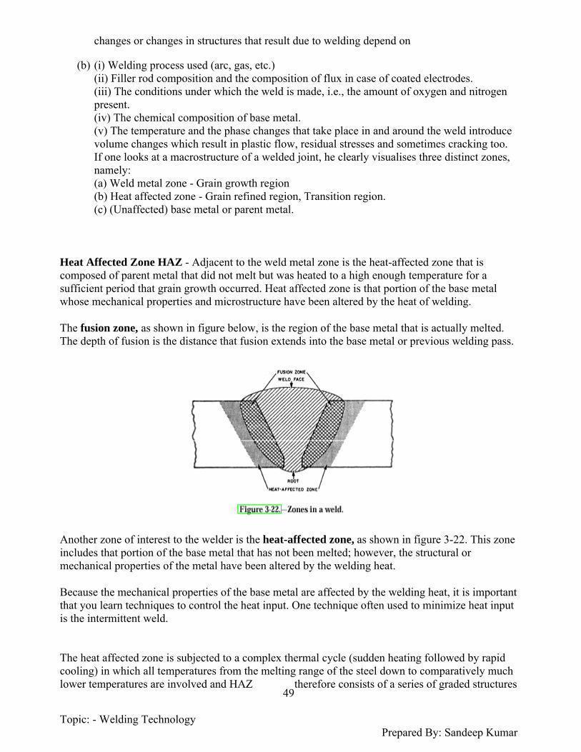
Topic: - Welding Technology Prepared By: Sandeep Kumar
49
changes or changes in structures that result due to welding depend on
(b) (i) Welding process used (arc, gas, etc.)(ii) Filler rod composition and the composition of flux in case of coated electrodes.(iii) The conditions under which the weld is made, i.e., the amount of oxygen and nitrogen present. (iv) The chemical composition of base metal.(v) The temperature and the phase changes that take place in and around the weld introduce volume changes which result in plastic flow, residual stresses and sometimes cracking too. If one looks at a macrostructure of a welded joint, he clearly visualises three distinct zones, namely: (a) Weld metal zone - Grain growth region(b) Heat affected zone - Grain refined region, Transition region.(c) (Unaffected) base metal or parent metal.
Heat Affected Zone HAZ - Adjacent to the weld metal zone is the heat-affected zone that is composed of parent metal that did not melt but was heated to a high enough temperature for a sufficient period that grain growth occurred. Heat affected zone is that portion of the base metal whose mechanical properties and microstructure have been altered by the heat of welding.
The fusion zone, as shown in figure below, is the region of the base metal that is actually melted. The depth of fusion is the distance that fusion extends into the base metal or previous welding pass.
Another zone of interest to the welder is the heat-affected zone, as shown in figure 3-22. This zone includes that portion of the base metal that has not been melted; however, the structural or mechanical properties of the metal have been altered by the welding heat.
Because the mechanical properties of the base metal are affected by the welding heat, it is important that you learn techniques to control the heat input. One technique often used to minimize heat input is the intermittent weld.
The heat affected zone is subjected to a complex thermal cycle (sudden heating followed by rapid cooling) in which all temperatures from the melting range of the steel down to comparatively much lower temperatures are involved and HAZ therefore consists of a series of graded structures

Topic: - Welding Technology Prepared By: Sandeep Kumar
50
ringing the weld bead. HAZ, usually contains a variety of microstructures
>In plain carbon steels these structures may range from very narrow regions of hard martensite to coarse pearlite. This renders HAZ, the weakest area in a weld. Except where there are obvious defects in the weld deposit, most welding failures originate in the heat affected zone. The heat affected zone is often defined (i.e., visualized) by the response of the welded joint to hardness or etching effect tests. The width of HAZ varies according to the welding process and technique; in arc welds it extends only a few mm from the fusion boundary, but in oxy acetylene and electroslag welds it is some what wider. The HAZ in low carbon steel of normal structure welded in one run with coated electrodes or by submerged arc process comprises three metallurgically distinguished regions
1. The grain growth region.2. The grain refined region.3. The transition region. (a) The grain growth region.Grain growth region is immediately adjacent to the weld metal zone (fusion boundary). In this zone parent metal has been heated to a temperature well above the upper critical (A3) temperature. This resulted in grain growth or coarsening of the structure. The maximum grain size and the extent of this grain growth region increase as the cooling rate decreases, and are greatest for electroslag welds. The large regions of pearlite and smaller grains of ferrite. (b) The grain refilled regionAdjacent to the grain growth region is the grain refined zone. The refined zone indicates that in this region, the parent metal has been heated to just above theA3 temperature where grain refinement is completed and the finest grain structure exists,
The structure of refined zone of the low carbon steel in question. Complete recrystallization is shown in which the ferrite (white) and pearlite (dark) areas are both much finer. (c) The Transition ZoneIn the transition zone, a temperature range exists between the Al and A3 transformation temperatures where partial allotropic recrystallization takes place. The structure of the transition zone of the low carbon steel in which the ferrite grains have not been altered but the pearlite regions have been made much finer. This change was produced by heating into the critical range which transformed the pearlite into austenite and by subsequent cooling reformed the pearlite. (d) Unaffected Parent MetalOutside the heat affected zone is the parent metal that was not heated sufficiently to change its microstructure. The typical grain structure of the parent metal [ferrite (white) and pearlite (dark)] which was welded and whose weld metal zone and HAZ microstructures were discussed and shown earlier.Q-WHAT IS THE HEAT AFFECTED ZONE AND HOW DOES IT AFFECT WELDABILITY?
The heating and cooling action that occurs when welding is a form of heat treating in the localized area of the puddle and weld joint that may result in changes to the mechanical properties of the base metal and surrounding area. The area most affected by heating and cooling during welding is called the HEAT AFFECTED ZONE (HAZ)
THE HEAT AFFECTED ZONE

Topic: - Welding Technology Prepared By: Sandeep Kumar
51
The heating and cooling rate of welding directly under the arc is from the melting temperature to normal temperatures and may occur relatively quickly or methods may be used to slow the cooling rate of the joint. These methods include postheating the weld area with an oxy-fuel torch, blanketing the weld area, or using a precise heating and cooling method in a furnace or industrial setting. The more expensive and precise method of using a furnace under controlled conditions restores the mechanical properties of the weld joint and the surrounding base metal. The area surrounding the joint is heated to various temperatures depending on the distance from the arc, the heat input of the process and the number of weld passes. This area is referred to as the Heat Affected Zone.
The grains structure in the melted weld area may form a desirable size and shape, while the grain structure of the surrounding heat affected area may change to a less desirable shape and size and may cause cracking when welding on medium or high carbon steels. Often when welding a hardenable steel the heat affected area can harden to undesirable levels, while welding an already hardened steel may result in a softened heat affected zone with loss of desired hardness.
The heat affected zone may also have locked in stresses that can lead to problems when the welded structure is in service. Some industries employ a heat treating process called stress relieving to relieve residual stresses due to working or welding the structure.
It is imperative to use the correct electrode for the application so that weld metal is compatible with the base metal and fewer changes occur due to the carbon or alloy content of the filler wire. Electrodes are available for welding tool steels and Cast iron.
When welding thick sections, medium carbon, high carbon, and high alloy steels check the recommended procedures for control of the heating and cooling rate
There are heat treating options such as annealing or normalizing that may be used to restore the grain structure of the welded piece.
When welding low carbon, mild steels and most low alloy steels the heat affected area does not change the properties of the metal enough to become a problem regardless of the cooling rate.
The heating and cooling that occurs in the heat affected area and surrounding metal may also lead to heat distortion of the parts being joined.
Procedures may be used before, during, and after welding to minimize distortion.
Grain Size Control - The grain size is a very important factor in considering the properties of polycrystalline materials because they affect the area and the length of the grain boundaries. Fine grained materials generally exhibit greater yield stresses than coarse grained materials at low temperatures whereas at high temperatures grain boundaries become weak and sliding occurs. The basic principle of grain size control is, In steel, grain refinement occurs only upon heating

Topic: - Welding Technology Prepared By: Sandeep Kumar
52
within or above the critical temperature range. Once an austenitic grain size has been established during heating, it cannot be refined during cooling, regardless of the cooling rate*.It can be refined, however, by subsequent reheating. In the case of pure metals and non-heat-treatable alloys, suitable grain refinement can be brought about by peening the weld, whilst still hot, and so bring about recrystallization.
Various factors controlling grain size are: (a) Annealing temperature (b) Annealing time (c) Rate of heating. Slow heating will form few nuclei, favour grain growth and result in coarse grain.(d) Degree of prior deformation. Heavy (prior) deformation favours the production of many nuclei on recrystallization and consequently the grain size will be small conversely the light deformation will give rise to few nuclei and result in large grain size. (e) Insoluble impurities. The greater the amount and the finer the distribution of insoluble impurities the finer is the final grain size. (f) Alloying elements such as nickel, limits grain growth during annealing and other heat-treatment processes in steels and in some non-ferrous alloys. The effect of some of these factors on grain size