welding abstracts...solutions for penetration problems when tig welding two pieces of 17-4ph...
TRANSCRIPT
ISSN 2049-8306
WELDING ABSTRACTS
The monthly abstracts journal for those seeking
technical knowledge about welding and allied processes,
and the science of joining
Welding Abstracts is the world’s most comprehensive abstracts journal in
the field of welding technology, providing fast, exhaustive coverage of
technical and business aspects of welding; equipment and materials;
properties and testing involving such essential topics as fatigue, corrosion,
and fracture mechanics; nondestructive testing and quality control;
nuclear engineering and offshore and underwater operations; and, of
general concern, codes and standards, education and training, and health
and safety.
Experts at TWI scan journals, books, conference proceedings, reports, etc
and produce hundreds of abstracts every month. These are transferred to
WELDASEARCH®, the world’s largest online database on welding, which
contains records dating back to 1967 and is available on the TWI website
(www.twi-global.com) or via Proquest Dialog, STN and Questel Orbit.
Editorial Staff
Sue Wellings
Alison Chew
Kath Millard
The abstracts herein are intended to represent the contents of the
original publications. All reasonable case is taken in abstracting and
editing, but TWI can accept no liability in respect of any error or
omission, or of any views expressed, which are those of the original
authors, not of TWI.
TWI

How to request photocopies of original articles
If you find an abstract of interest in Welding Abstracts and would like a copy of the original article, please contact the TWI library. Copies will be supplied where possible, allowing for restrictions (e.g. copyright). Copies are dispatched electronically unless you request otherwise. Charges Please contact the TWI library for information concerning charges for copies. Searching the Weldasearch database
The Weldasearch database is available for searching on the TWI website (https://www.twi-global.com/technical-knowledge). This service is free to TWI members. Please contact the Weldasearch team if you would like them to carry out a search of the Weldasearch database on your behalf. Contact details Email: [email protected] Address: Library, TWI Ltd, Granta Park, Great Abington, Cambridge CB21 6AL, UK Telephone: +44 (0)1223 899000
Abstracts - layout explained iv
PROCESSES
01 ARC WELDING 102 RESISTANCE WELDING 303 ENERGY BEAM PROCESSES 307 OTHER JOINING PROCESSES 408 THERMAL CUTTING 509 SURFACING 612 ANCILLARY OPERATIONS 7
PRODUCTION
23 REPAIR AND MAINTENANCE 7
EQUIPMENT AND MATERIALS
30 EQUIPMENT [FOR WELDING, ETC.] 832 MATERIALS, GENERAL 9
PROPERTIES AND TESTING
40 TENSILE PROPERTIES, TOUGHNESS 941 FATIGUE 1042 OTHER MECHANICAL PROPERTIES 1243 CORROSION 1344 WELDABILITY AND METALLURGY 1445 RESIDUAL STRESSES 1646 FRACTURE MECHANICS 1747 NONDESTRUCTIVE TESTING 2148 QUALITY CONTROL 23
MANUFACTURING AND CONSTRUCTION
50 NUCLEAR ENGINEERING 2352 PIPES, PIPELINES AND VESSELS 24
GENERAL
60 CODES AND STANDARDS 2963 HEALTH AND SAFETY 31
AUTHOR INDEX 33
COMPANY INDEX 38
SUBJECT INDEX 39
Welding Abstracts Vol.32, No.9, September 2019
Contents
Weldasearch Numbers 277320 - 277469
Copyright © 2019, TWI Ltd
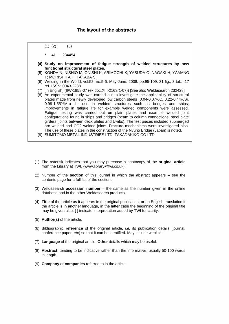
The layout of the abstracts
(1) The asterisk indicates that you may purchase a photocopy of the original article from the Library at TWI. ([email protected]).
(2) Number of the section of this journal in which the abstract appears � see the
contents page for a full list of the sections.
(3) Weldasearch accession number � the same as the number given in the online database and in the other Weldasearch products.
(4) Title of the article as it appears in the original publication, or an English translation if
the article is in another language, in the latter case the beginning of the original title may be given also. [ ] indicate interpretation added by TWI for clarity.
(5) Author(s) of the article.
(6) Bibliographic reference of the original article, i.e. its publication details (journal,
conference paper, etc) so that it can be identified. May include weblink.
(7) Language of the original article. Other details which may be useful.
(8) Abstract, tending to be indicative rather than the informative; usually 50-100 words in length.
(9) Company or companies referred to in the article.
(1) (2) (3) * 41 - 234454
(4) Study on improvement of fatigue strength of welded structures by new functional structural steel plates.
(5) KONDA N; NISHIO M; ONISHI K; ARIMOCHI K; YASUDA O; NAGAKI H; YAMANO T; MORISHITA H; TAKABA S
(6) Welding in the World, vol.52, no.5-6. May-June. 2008. pp.95-109. 31 fig., 3 tab., 17 ref. ISSN: 0043-2288
(7) [in English] (IIW-1858-07 (ex doc.XIII-2163r1-07)) [See also Weldasearch 232428] (8) An experimental study was carried out to investigate the applicability of structural
plates made from newly developed low carbon steels (0.04-0.07%C, 0.22-0.44%Si, 0.99-1.55%Mn) for use in welded structures such as bridges and ships; improvements in fatigue life for example welded components were assessed. Fatigue testing was carried out on plain plates and example welded joint configurations found in ships and bridges (beam to column connections, steel plate girders, joints between deck plates and U-ribs). The test pieces included submerged arc welded and CO2 welded joints. Fracture mechanisms were investigated also. The use of these plates in the construction of the Nyuno Bridge (Japan) is noted.
(9) SUMITOMO METAL INDUSTRIES LTD; TAKADAKIKO CO LTD
01 ARC WELDING
See also abstracts: 09-277353, 30-277333, 40-277322, 40-277358,40-277404, 42-277368, 44-277360, 44-277367, 45-277363
01-277323The effect of SiC addition on microstructure and mechanicalproperties of gas tungsten arc [TIG]-welded Ti-6Al-4V alloy.LANGEN D; MAIER H J; HASSEL TJournal of Materials Engineering and Performance, vol.27, no.1.Jan.2018. pp.253-260. 13 fig., 2 tab., 18 ref. ISSN: 1059-9495[in English][https://link.springer.com/article/10.1007%2Fs11665-017-3091-y]The influence of silicon carbide (SiC) addition on the microstructure,mechanical properties and grain size of TIG welded Ti6Al4V alloy wasstudied. A groove (0.4 mm depth, 5 mm width) was milled along thelongitudinal axis of Ti6Al4V (Ti, 6.33%Al, 3.94%V) specimens (120 x68 x 3 mm), filled with SiC and subjected to bead-on-plate welding(current 80 A, shielding gas argon 4 l/min, standoff distance 3 mm,travel speed 100 mm/min) with filler wire (Ti, 6.05%Al, 4.10%V).Fusion joint welding (current 80 A, shielding gas argon 4 l/min,standoff distance 1 mm, travel speed 120 mm/min, wire feed 0.4m/min) was performed on Ti6Al4V alloy sheet metal (2 mm thickness;Ti, 6.15%Al, 3.80%V) with a V-shaped butt joint preparation withoutroot face and bevel angle of 45 degrees, coated with SiC powder. Thetensile strength, strain, microstructure and hardness of the joints wereanalysed and compared with those with no SiC additions.
01-277325Microstructures and mechanical properties of plasma arc weldedjoints of ultra-high strength steel and aluminium alloy usingAl-Si and Al-Cu fillers.GENG W H; WU D; SUN D Q; LI H M; CHE Y YISIJ International, vol.58, no.6. June 2018. pp.1108-1116. 11 fig., 3tab., 31 ref. ISSNs: 0915-1559, 1347-5460[in English][https://tinyurl.com/ybx2g48a]The weld appearance, microstructure and mechanical properties ofplasma arc welded joints of ultra high strength steel and aluminiumalloy were investigated. Ultra high strength steel (1180DP - max.0.23%C, 3%Mn) and aluminium alloy (5A06 - Al, 6.25%Mg,0.72%Mn, 0.21%Fe) sheets of 3 mm thickness were welded usingdifferent preparations (steel bevel angle 45 degrees; aluminium alloyangle 0, 30 and 45 degrees). Filler materials used were: Al-Si (ER 4043- Al, 5%Si, max. 0.25%Cr, max. 0.2%Zn) and Al-Cu (ER 2319 - Al,5.8-6.8%Cu, 0.2-0.4%Mn, 0.2-0.4%Mg). Welding parameters usedwere: current 80-110 A; speed 32 cm/min; wire feed rate 300 cm/min;Ar shielding gas flow rate 23 l/min; plasma gas flow rate 2.3 l/min. Themicrostructure characteristics of the weld zone, bond zone andinterface zone of the welded joints were examined by SEM, X-raydiffraction, energy dispersive spectroscopy and transmission electronmicroscopy. Diffraction patterns and the interdiffusion of Fe and Al inthe interface zone were measured and compared. The effect on theweld appearance of the joint preparations was analysed. The weldingparameters and filler wire composition and their effect on the thicknessof the interface layer, and the microhardness, tensile strength andfracture surface morphology of the welded joints were investigated.
01-277331Peculiarities of development of structural heterogeneity in thefusion zone of pearlite steel with austenitic nitrogen-containingweld metal.ELAGIN V P; LIPODAEV V N; GORDAN G NPaton Welding Journal, no.8. Aug.2016. pp.23-28. 7 fig., 14 ref. ISSN:0957-798X[in English and Russian] (Translated from Avtomaticheskaya Svarka)[See also Weldasearch 156521][https://patonpublishinghouse.com/eng/journals/tpwj/2016/08/05/]Structural heterogeneity at the weld metal and pearlitic steel parentmaterial interface was studied for welds produced using austenitic steelfiller materials and operating at high temperature. To study theinfluence of the nickel content of the filler material and the nitrogencontent of the weld metal on carbon diffusion from the parent materialleading to embrittlement, bead on plate welds were produced on lowcarbon steel plate (20-22 mm thickness) by MIG/MAG welding usingaustenitic steel 08Kh20N9G7T, 08Kh20N25M8G8 and08Kh25N40M7 filler wires of 1.2 mm diameter, with argon, carbondioxide, nitrogen, and CO2, 5-80%N2 shielding gases, to vary thenitrogen content of the weld metal. The welding parameters were:current 240-260 A; voltage 24-26 V; speed 16 or 25 m/h; energy inputsof 0.41 and 0.79 kJ/cm. Service conditions were simulated by heatingthe specimens to 550 deg.C for 1000-3000 h. Composition (includingcarbon distribution), microhardness, and microstructure (including theformation of carbides, nitrides and a ferrite interlayer in the HAZ) werecharacterised. Lack of penetration low carbon steel plate butt weldswere produced using 08Kh20N9G7T filler wire and CO2, 2%N2shielding gas; and using 08Kh25N40M7 filler wire with Ar shieldinggas. The specimens were subjected to heat treatment (550 deg.C, 3000h) and embrittlement assessed by bend testing.
01-277335Stainless Q&A [Questions and Answers] [TIG welding of 17-4PHstainless steel].KOTECKI D JWelding Journal, vol.97, no.9. Sep. 2018. pp.20-21. 2 fig., 1 ref. ISSN:0043-2296[in English][https://bit.ly/33Fu8qp]Solutions for penetration problems when TIG welding two pieces of17-4PH stainless steel (16%Cr, 4%Ni, 4%Cu) in a lap jointconfiguration using a lathe welding machine are presented. A fusionrun, the first of two TIG welding runs performed, resulted in wide andshallow penetration. The Marangoni Effect, where a fluid flow in aliquid is driven by a surface tension gradient, is explained. The effect ofsulphur content on the direction of the surface tension and the use ofargon-oxygen decarburisation (AOD) to deal with very low sulphurcontent (0.010%) are discussed. Overcoming the penetration problemof 17-4PH with very low sulphur content (0.0003%) by painting apenetration enhancing flux on the joint surfaces before welding isbriefly described.
01-277340Influence of multiple Gleeble - simulated weld thermal cycles onmaraging 17-4 and 13-8+Mo.HAMLIN R J; DUPONT I NWelding Journal, vol.97, no.9. Sep. 2018. Supplement: WeldingResearch. pp.253s-262s. 13 fig., 2 tab., 29 ref. ISSN: 0043-2296[in English][https://bit.ly/2Zf9zSn]The effects of multirun welding represented by primary and secondary
Welding Abstracts, Vol.32, No.9, September 2019 1 ARC WELDING
Copyright © 2019, TWI Ltd
welding thermal cycles, on maraging 17-4 and 13-8+Mo stainless steelswas investigated. PH-17-4 (0.03%C, 0.41%Mn, 16.08%Cr, 4.09%Ni,0.21%Mo, 0.20%Nb) and PH-13-8+Mo (0.06%C, 0.19%Mn,12.71%Cr, 7.90%Ni, 2.27%Mo) plates were solution treated at 1052deg.C and 926 deg.C respectively. The 17-4 samples were air cooled toroom temperature and aged for 1.5 h at 579 deg.C. The 13-8+Mosamples were argon gas cooled, water quenched to 15 deg.C and aged at593 deg.C for 4 h. Autogenous TIG welding was performed on sheets(1.27 cm thickness) of each material using current 200 A, voltage 10 V,travel speed 1 mm/s, argon shielding gas and various combinations ofsimulated welding thermal cycles (650-1300 deg.C, 650-1150 deg.C,650-875 deg.C; 1000 and 2000 J/mm heat input), representative ofmultirun welding, using a thermo-mechanical simulator. The hardnessof the samples was determined and microstructure analysed. Theresults are discussed with regard to the hardening behaviour and matrixmicrostructures of the parent material and weld metal.
01-277357Characteristics of hot cracking in dissimilar joint of A690 overlayand stainless steel clad.KO G B; SEO K M; KIM H J; HONG HWelding in the World, vol.61, no.5. Sep. 2017. pp.945-953. 12 fig., 4tab., 19 ref. ISSN: 0043-2288[in English][https://rd.springer.com/article/10.1007%2Fs40194-017-0477-2]The hot cracking behaviour and characteristics of a joint between A690Nb-containing solid-solution Ni-base alloy overlay and stainless steelwere investigated. Submerged arc welding (SAW) was used to deposit309L (first layer) and 308L (second layer) stainless steel stripelectrodes (thickness 0.5 mm) onto SA 508 Gr3 (0.24%C, 1.41%Mn,0.22%Cr, 0.91%Ni) steel plate (40 mm thickness). Bead on platewelds of A690 nickel alloy (Ni, 30%Cr, 9.44%Fe, 3.34%Mn,1.86%Nb) were deposited onto the 308L layer (0.028%C, 1.82%Mn,20.7%Cr, 10%Ni, 0.006%Nb, 0.007%Ti) using MMA weldingprocess (current 130-140 A; voltage 30 V; welding speed 150 mm/min)as a single run or as three runs. The microstructure and phasecomposition of the A690 weld bead and the 308L deposited layer weredetermined. The proportion of Laves phase distribution, the Fecontent in the A690 weld near the welded joint, and liquation crackingsusceptibility were observed and the results are discussed.
01-277359Single pass full penetration joining for heavy plate steel usinghigh current GMA [MIG/MAG] process.BABA H; ERA T; UEYAMA T; TANAKA MWelding in the World, vol.61, no.5. Sep. 2017. pp.963-969. 11 fig., 2tab., 15 ref. ISSN: 0043-2288[in English] [See also Weldasearch 273910][https://rd.springer.com/article/10.1007%2Fs40194-017-0464-7]A MAG welding system based on current waveform control with100% CO2 shielding gas was developed to facilitate single-runfull-penetration welding of a structural steel heavy plate (thickness 25mm) and metal transfer modes and high-current buried arc stabilisationcharacteristics were investigated. The materials studied were a JISSS400 carbon steel parent metal and a JIS YGW12 carbon steel fillerwire. Buried arc phenomena were observed by a high-brightness X-raysystem and a high-speed video camera. Drop, pendulum and rotatingmetal transfer modes were examined at wire feed rates of 30, 50 and 60m/min, respectively. Issues discussed include arc generation under thesurface of the molten pool, spatter generation reduction and arcstabilisation by low-frequency modulated voltage control.
01-277361A study on sidewall penetration of cable-type welding wireelectrogas welding.CHEN Y; FANG C F; YANG Z D; WANG J Y; WU M FWelding in the World, vol.61, no.5. Sep. 2017. pp.979-986. 12 fig., 4tab., 22 ref. ISSN: 0043-2288[in English] [See also Weldasearch 275637][https://rd.springer.com/article/10.1007%2Fs40194-017-0479-0]The sidewall penetration mechanism of cable type welding wireelectrogas welding (CWW-EGW) was studied. This process uses cabletype welding wire (CWW) as the consumable electrode, with up toseven wires able to be melted simultaneously using a single powersource, wire feeder and welding torch. Joints were fabricated in steelsubstrates (max. 0.18%C, 0.9-1.6%Mn, 0.05-0.1%V; 30 mmthickness) using CWW-EGW (3 mm diameter) or single-wire EGW(1.6 mm diameter) under CO2 shielding gas at 28 L/min. Weldingparameters used were: current 380-475 A; voltage 37.0-42.6 V; weldingtorch swing 5-15 mm; welding torch dwell time 0-2.5 s. Welding arc,droplet transfer and sidewall penetration were monitored by a highspeed digital camera. Microstructure, elongation, tensile strength andhardness of the welded joints were determined. The influence ofdroplet transfer on sidewall penetration during CWW-EGW wasevaluated.
01-277366Effect of rare earth metal on plasma properties in GMAW[MIG/MAG] using CO2 shielding gas.METHONG T; YAMAGUCHI T; SHIGETA M; TANAKA M;IKEDA R; MATSUSHITA M; POOPAT BWelding in the World, vol.61, no.5. Sep. 2017. pp.1039-1047. 15 fig., 1tab., 23 ref. ISSN: 0043-2288[in English] [See also Weldasearch 240813][https://rd.springer.com/article/10.1007%2Fs40194-017-0491-4]The influence of polarity and rare earth metal (REM) content on theplasma properties during MAG welding was investigated usingoptimal emission spectroscopy. Welding of SS400 carbon steelsubstrate was carried out using MG-50 wire electrode (0.04%C,1.58%Mn, 0.22%Ti; 1.2 mm diameter) or KC-500 wire electrode(0.05%C, 1.6%Mn, 0.2%Ti, added REM; 1.2 mm diameter) underCO2 shielding gas at 20 L/min, in either direct current electrodepositive (DCEP) or direct current electrode negative (DCEN) polarity.Welding parameters used were: current 300 A; voltage 33.5 V; weldingtravel speed 60 cm/min. Arc plasma temperature, electron density, andmetal vapour concentrations were determined. The spectroscopic datawere evaluated and compared with images from a high speed camera.The maximal temperature and distribution in the plasma region weredetermined. The relationship between the REM addition and highcurrent density, electromagnetic pinch force and droplet diameterbriefly discussed.
01-277461Elucidation of the weld pool convection and keyhole formationmechanism in the keyhole plasma arc welding.WU D S; NGUYEN A V; TASHIRO S; HUA X M; TANAKA MInternational Journal of Heat and Mass Transfer, vol.131. Mar. 2019.pp.920-931. 21 fig., 1 tab., 44 ref. ISSN: 0017-9310[in English] [See also Weldasearch 245904 and 273811]Weld pool convection and keyhole formation mechanism in keyholeplasma arc welding (KPAW) of stainless steel (SS) was investigated,using numerical simulation. An electrode-arc model was developed toexamine the plasma arc physics in KPAW, and to obtain significantparameters related to the current density, arc pressure and plasma
ARC WELDING 2 Welding Abstracts, Vol.32, No.9, September 2019
Copyright © 2019, TWI Ltd

shear stress. A 3D weld pool model was developed based on aself-adaptive heat source model, arc pressure model and plasma shearstress model, to examine the weld pool convection and keyholeformation. Numerical simulation was applied to the KPAW of SUS304SS sheet (thickness 4 mm), to examine weld pool convection (beforeand after penetrated keyhole formation) and the keyhole formationmechanism. Welding experiments were conducted on SUS304 SS sheets(thickness 4 mm) using KPAW (direct current 120 A; output arcvoltage 27 V; welding speed 3 mm/s; argon main plasma gas flow rate1.7 l/min; argon shielding gas flow rate at 7.5 l/min). Convectivepatterns inside the weld pool were estimated by use of an X-raytransmission system to observe the movement of W particles.Convective patterns on the weld pool surface were measured by use ofa high speed video camera to observe the movement of ZrO2 particles.Temperature distributions at the weld pool surfaces were measuredwith a thermal camera. Numerical simulation and experimental resultsare compared.
02 RESISTANCE WELDING
02-277324Quality estimation in small scale resistance spot welding oftitanium alloy based on dynamic electrical signals.WAN X D; WANG Y X; ZHAO D WISIJ International, vol.58, no.4. Apr.2018. pp.721-726. 7 fig., 1 tab.,21 ref. ISSNs: 0915-1559, 1347-5460[in English] [See also Weldasearch 259881][https://www.jstage.jst.go.jp/article/isijinternational/58/4/58_ISIJINT-2017-282/_article]The development of a quality monitoring system in small scaleresistance spot welding (SSRSW) of titanium alloy was investigated.Sheets of Ti alloy TC2 (Ti, 3.5-5.0%Al, 0.8-2.0%Mn, 0.30%Fe,0.15%O, 0.10%C, 0.05%N) of 0.4 mm thickness were spot welded ina series of tests. Electrode force was varied from 75 to 200 N, weldingcurrent from 1.0 to 2.4 kA, and welding time from 4 to 12 milliseconds.Tensile shear strength of the welded joints was determined and thenugget size was measured. The effect of varied parameters on dynamicresistance; nugget size; weld quality; and detection of weld expulsionwere determined. A back propagation neural network (BPNN) analysiswas carried out, using proprietary software for model training andvalidation. The nugget size predictions were compared withexperimental values. A brief assessment of the accuracy of usingBPNN with dynamic resistance signals for quality monitoring andclassification purposes is given.
03 ENERGY BEAM PROCESSES
See also abstracts: 08-277347, 09-277460, 30-277342, 30-277343,30-277344, 30-277345, 40-277358
03-277320Experimental study of the microstructure and micromechanicalproperties of laser cladded Ni-based amorphous compositecoatings.LI R F; ZHENG Q C; ZHU Y Y; LI Z G; FENG K; LIU CJournal of Materials Engineering and Performance, vol.27, no.1.Jan.2018. pp.80-88. 14 fig., 1 tab., 27 ref. ISSN: 1059-9495[in English][https://link.springer.com/article/10.1007%2Fs11665-017-3066-z]The microstructure of NiFeBSiNbC amorphous composite coatingfabricated using laser surfacing was investigated.
(Ni0.6Fe0.4)65B18Si10Nb4C3 (atomic %) coating was deposited onAISI 1045 steel (150 x 15 x 10 mm) using a fibre laser with a coaxialpowder delivery nozzle. The laser beam focused on a 5 x 5 mm spot onthe parent material, the powder was dried for 2 hours at 200 deg.Cbefore surfacing and argon shielding gas was used at 10 l/min. Theprocess parameters were laser power 2100-4200 W, scanning speed16-80 mm/s, feeding rate 13.3-20.9 g/min, heat input 52.5-131.3 J/mm,coating thickness 0.19-0.45 mm, heat affected zone (HAZ) 0.41-0.59mm. The microstructure was analysed as a function of laser heat input,and the hardness and indentations determined. Theoretical results,predicted using the Orowan-Ashby equation, were compared with theexperimental results.
03-277321Effects of the electron beam welding process on themicrostructure, tensile, fatigue and fracture properties of nickelalloy Nimonic 80A.ZHANG H; HUANG C X; GUAN Z W; LI J K; LIU Y J;CHEN R H; WANG Q YJournal of Materials Engineering and Performance, vol.27, no.1.Jan.2018. pp.89-98. 14 fig., 2 tab., 36 ref. ISSN: 1059-9495[in English][https://link.springer.com/article/10.1007%2Fs11665-017-3068-x]The effect of electron beam welding (EBW) on the microstructure,rotary bending fatigue properties and mechanical behaviour of Nimonic80-A was studied. Two plates (200 x 45 x 14 mm) of forged nickelalloy Nimonic 80-A (Ni, 0.04-0.10%C, 18.0-21.0%Cr, 1.00-1.80%Al,1.8-2.7%Ti,) underwent EBW butt welding with welding parametersaccelerating voltage 85 kV, beam current 40 mA, cathode heatingcurrent 20 A, vacuum in working chamber 0.08 mBar and weldingvelocity 1400 mm/min. The stress distribution was calculated usingfinite element method (FEM). The hardness, rotary bending fatigue andfatigue crack growth were determined. The results are discussed withregard to the microstructure, tensile properties, microhardness, rotarybending high-cycle fatigue properties, cyclic stress versus variation offatigue life and fatigue crack growth properties of the alloy, and itsweldment.
03-277330Formation of weld metal structure in electron beam welding ofsingle crystals of high-temperature nickel alloys.YUSHCHENKO K A; ZADERY B A; GAKH I S;KARASEVSKAYA O PPaton Welding Journal, no.8. Aug.2016. pp.15-22. 10 fig., 4 tab., 23ref. ISSN: 0957-798X[in English and Russian] (Translated from Avtomaticheskaya Svarka)[See also Weldasearch 236418][https://patonpublishinghouse.com/eng/journals/tpwj/2016/08/04/]The influence of the orientation and welding parameters on moltenpool crystal orientation in EB welded nickel alloy single crystal weldswas investigated. Bead on plate welds were produced on sheetspecimens of single crystal high temperature nickel alloys JS26 (Ni,9.0%Co, 5-15%W, 5.0%Cr, 4.5-8.0%Al, 1.6%Nb, 1.0%V,0.5-5.0%Mo, 0.2-4.0%Ti) and JS32 (Ni, 9.3%Co, 2-10%W, 5.0%Cr,4.5-8.0%Al, 4.0%Re, 4.0%Ta, 1.5-5.0%Nb, 0.5-5.0%Mo) by EBwelding at speeds of up to 90 m/h, with other welding parameterschosen to ensure full penetration. Heating and cooling rates of themolten pool were measured. The gamma phase dispersion, dendritespacing, phase composition, carbide precipitates, dislocation densityand distribution, and the presence of randomly oriented grains weredetermined. Numerical modelling was used to study the solidification
Welding Abstracts, Vol.32, No.9, September 2019 3 RESISTANCE WELDING
Copyright © 2019, TWI Ltd

of the molten pool, and the range of solidification temperature rates forwhich no randomly oriented grains were formed were established.
03-277338Laser welding Q&A [Questions and Answers] [focused spot sizein laser welding].ENGEL S LWelding Journal, vol.97, no.9. Sep. 2018. pp.44-45. 3 fig., 3 ref. ISSN:0043-2296[in English][https://bit.ly/2z7eaHs]Focus shift and its effects on focused spot size in laser welding isbriefly discussed. Focus shift is defined. Sources for focus shiftincluding changes in the laser beam divergence and the build-up of heatin the beam optics are discussed. Solutions for uncontrolled divergenceof laser beams are provided which involve installing a collimator orbeam expander between the laser and focusing lens. An example isgiven of an Nd:YAG laser with power increasing from 50 to 500 W,and the distance between the two optics shortened by approximately3.81 cm to maintain collimation. Methods to solve heat build-up inoptics by using metal mirror focusing heads and by controlling theeffect of heat (cleaning optical surfaces, use of long focal length optics,and optics coatings) are briefly discussed.
03-277346Japan develops blue laser for advanced materials processing.TOJO K; MASUNO S; HIGASHINO R; TSUKAMOTO MIndustrial Laser Solutions for Manufacturing. Sept.-Oct. 2018.pp.27-31. 12 fig., 1 tab., 10 ref. ISSN: 1523-4266[in English]An overview of a research and development project in Japan into anext-generation laser processing system based on high-power blue laserdiodes is presented. The Development of Advanced Laser Processingwith Intelligence Based on High-Brightness and High-Efficiency LaserTechnologies (2016-2020) project seeks to develop BLUE IMPACT, afibre-coupled high-brightness blue diode laser module that combinesblue direct diode lasers (B-DDLs) in order to achieve a high poweroutput (100 W from a 0.1 mm diameter fibre). The basic technology,combining technology and characteristics of the B-DDL are discussed,and examples of laser processing, lap welding and 3D printing with aBLUE IMPACT module are described.
03-277355Experimental measurements and numerical simulations ofdistortions of overlap laser-welded thin sheet steel beamstructures.ANDERSSON O; BUDAK N; MELANDER A; PALMQUIST NWelding in the World, vol.61, no.5. Sep. 2017. pp.927-934. 6 fig., 2tab., 15 ref. ISSN: 0043-2288[in English][https://rd.springer.com/article/10.1007%2Fs40194-017-0496-z]Distortions in overlap laser welded beam structures of thin sheets ofmild steel, used in automotive applications, were investigatedexperimentally and numerically. Overlap joints were fabricatedbetween thin sheet and U-beam structures of uncoated mild steelVDA-100 CR-3 (0.08%C, 0.5%Mn, 0.3%Ti) by Nd:YAG laser(welding power 2400-4000 W; welding velocity 40-80 mm/s; sheetthickness 1.0-1.5 mm) in intermittent or continuous welding patterns.The influence of intermittent welding, heat input per length, weldlength and sheet thickness on vertical and transverse distortions after
cooling was examined. The welding distortions and shrinkage of theweld zone during cooling were modelled using finite elementsimulations and compared with experimental results.
03-277467Comparison of electron beam and laser welding for safety criticalspace applications.MITCHELL T; ALLEN C; NORMAN AE+E (Electrotechnica & Electronica), vol.53, no.9-10. 2018. SpecialIssue: Scientific papers from 13th International Conference on ElectronBeam Technologies, Varna, Bulgaria, 18-22 June 2018. pp.241-247. 19fig., 2 tab., 3 ref. ISSN: 0861-4717[in English][https://epluse.tceptt.com/comparison-of-electron-beam-and-laser-welding-for-safety-critical-space-applications/]Electron beam (EB) and laser welding of stainless steel wereinvestigated and compared, for producing propellant flow controlvalves (FCVs) used to position satellites for space applications. A 60kV 4 kW EB welding system with a fixed welding speed (20 mm/s)was evaluated (with and without beam deflection) by identifyingsuitable welding parameters by beam current adjustment to achievepartial penetrated joints with penetration depths of 0.2-1.5 mm.Multi-kilowatt CW fibre laser welding was evaluated for achievingpenetration depths of 0.7-1.5 mm by altering the welding speed (laserpower 1.5-2 kW; welding speed 4.5-9.5 m/min). Subkilowatt andpulsed laser welding were evaluated for producing shallow welds(penetration depth 0.2-0.7 mm), using a quasi continuous wave (QCW)fibre laser at a fixed welding speed with heat inputs 5-25 J/mm. Partialpenetration butt welds between 347, 430 ferritic and 17-7 martensiticstainless steels (thickness 2 mm or less) were produced. Investigationscovered: measurement of penetration depths and surface profiles of thewelds; determination of the microstructure (including defects), tensileproperties, hardness, stress corrosion cracking tendency, fracturetoughness and fatigue crack growth resistance of the welds;nondestructive inspection of the welds; pressure, proof and rupturetesting of demonstrator components; and microstructural observationsof failed welds after various testing procedures.
07 OTHER JOINING PROCESSES
See also abstracts: 47-277406
07-277326Effect of post-weld heat treatment on the dissimilar Cu/Al jointsproduced by high power ultrasonic spot welding.GU X Y; LIU D F; LIU JISIJ International, vol.58, no.9. Sept.2018. pp.1721-1726. 11 fig., 3tab., 20 ref. ISSNs: 0915-1559, 1347-5460[in English][https://www.jstage.jst.go.jp/article/isijinternational/58/9/58_ISIJINT-2017-694/_article]Effect of post weld heat treatment (PWHT) temperature on themicrostructure and mechanical properties of lap spot ultrasonic weldsbetween sheets of Cu and aluminium alloy was investigated. 1 mthickness sheets of Cu (top) and Al 6082-T6 alloy (Al, 0.4-1%Mn,0.7-1.3%Si, 0.6-1.2%Mg) were ultrasonically welded at 1.4 kJ, 9.5micrometres amplitude, 0.4 MPa static pressure, and PWHT at200-500 deg.C for 1 h with furnace cooling. Sonotrode size was 5.2 x7.8 mm, and joint overlap was 20 mm. Microstructure, composition,
OTHER JOINING PROCESSES 4 Welding Abstracts, Vol.32, No.9, September 2019
Copyright © 2019, TWI Ltd

hardness and shear strength of the weld joints was studied as afunction of PWHT temperature, with special emphasis onmicrostructural changes at the weld interface.
07-277332Electroslag welding of large-sized press frame.SHAPOVALOV K P; BELINSKY V A; MERZLYAKOV A E;KOSINOV S N; YUSHCHENKO K A; LYCHKO I I;KOZULIN S MPaton Welding Journal, no.8. Aug.2016. pp.36-39. 4 fig., 8 ref. ISSN:0957-798X[in English and Russian] (Translated from Avtomaticheskaya Svarka)[https://patonpublishinghouse.com/eng/journals/tpwj/2016/08/07/]The electroslag welding of a section of a steel hydraulic press frame,with a mass of 160-200 tonnes, is described. The frame, with a seriesof longitudinal and transverse ribs, was fabricated by joining two castsections of 30L carbon steel at their faces (3820 x 3130 mm).Distortion during welding was minimised by the presence of the ribsand by slowly preheating the joint to 500-600 deg.C. The joint gap atthe bottom and the top was 36 mm and 40 mm, respectively. Sixgroups of consumable guides and four power sources were used.
07-277354A study on the characteristics of FSW [friction stir welding] toolshapes based on CFD [computational fluid dynamics] analysis.KIM S D; YOON J Y; NA S JWelding in the World, vol.61, no.5. Sep. 2017. pp.915-926. 13 fig., 2tab., 20 ref. ISSN: 0043-2288[in English][https://rd.springer.com/article/10.1007%2Fs40194-017-0478-1]The influence of tool shape on friction stir welding was studied usingcomputational fluid dynamics. A new interface tracking algorithm wasintroduced in the model, which used a grid based system to express therotating and moving motions of a tool simultaneously on the workpiecematerial AA5052. The algorithm was applied to cylinder, screw andtap shapes of the welding tool under FSW (welding speed 50 mm/min;rotational speed 600 rpm) and cylinder shape under friction stir spotwelding (FSSW) (rotational speed 1000 rpm). Determined temperatureand torque history were compared with FSW and FSSW experimentalresults. Velocity distribution, viscosity distribution and fluid flowpattern were used to analyse the characteristics of the tool shapes.
07-277365Decomposition of ultrasonically welded carbon fibre/polyamide66 and its effect on weld quality.ZHI Q; TAN X R; LU L; CHEN L Y; LI J C; LIU Z XWelding in the World, vol.61, no.5. Sep. 2017. pp.1017-1028. 17 fig., 1tab., 25 ref. ISSN: 0043-2288[in English] [See also Weldasearch 275455][https://rd.springer.com/article/10.1007%2Fs40194-017-0482-5]The influence of weld energy on the strength of ultrasonically weldedcarbon fibre/polyamide (CF-PA66) composite structures wasinvestigated. Joints were fabricated in carbon fibre/polyamide 66 (4mm thickness) using ultrasonic welding in a shear lap configuration.Ultrasonic welding was conducted using a machine with differentwelding modes: energy, time and collapse modes. The samples werewelded in each mode using the nominal settings of the machine (power2.6 kW, frequency 20 kHz, and amplitude 0.025 mm). Ultrasonic weldenergy parameters used were 3000-8000 J. Weld quality was assessedfrom microstructure, indentation, fracture surfaces, interfaces,porosity, temperature profile, and decomposition/degradation. The
relationship between weld energy and joint quality was examined andanalysed. A decomposition index was also proposed and to evaluateweld quality.
07-277462Stacking-fault energy, mechanical twinning and strainhardening of Fe-18Mn-0.6C-(0, 1.5)Al twinning-induced plasticitysteels during friction stir welding.LEE S J; SUN Y F; FUJII HActa Materialia, vol.148. 15 Apr. 2018. pp.235-248. 10 fig., 3 tab., 45ref. ISSN: 1359-6454[in English] [See also Weldasearch 267571]Friction stir welding (FSW) at different welding speeds of twinninginduced plasticity (TWIP) steels was investigated, to determine theeffect of welding speed, microstructural changes (grain size, dislocationdensity, twin density), stacking fault energy, and strain hardening rate(SHR) during FSW. Ingots in Fe-Mn-C (Fe, 18%Mn, 0.6%C) andFe-Mn-C-Al (Fe, 18%Mn, 0.6%C, 1.5%Al) were melted using a highfrequency induction furnace, the ingots were solution treated, hotrolled, and then air cooled to room temperature. The plates were thencold rolled at room temperature to a sheet thickness of 2 mm. Coldrolled sheets were subjected to FSW using a tungsten carbide FSW tool(welding speed 50-200 mm/min; rotation speed 400 rpm; loading of2000 kg; advancing tilting angle 3 degrees). Investigations covered:determination of the microstructure, grain size and distribution, phasecontent, phase transformations, dislocation density, and misorientationangles of the parent metals and welded joints; measurement of tensileproperties and hardness distributions of the welded joints;determination of the SHR, generation and growth of mechanical twins,and deformation induced local misorientation during and after tensiletesting of the joints; stacking fault energy and critical stress formechanical twinning; comparison of the experimental results for thedifferent TWIP steel compositions; and the relationships betweenmicrostructural changes and mechanical properties.
08 THERMAL CUTTING
08-277347Laser machine helps tube fabricator perfect storage system,launch new company - storage rack manufacturer relies onmachine's accuracy, repeatability for making precise tube weldjoints.LUNDIN ETube and Pipe Journal. Oct.-Nov.2018. pp.18-23. 1 fig. ISSN:1091-2479[in English]The implementation of laser cutting to produce components for themanufacture of storage rack systems is described. The laser cuttingmachine from BLM Group USA was installed by storage rackmanufacturer Technique Inc of Jackson, MI, US, to ensure accuracy,repeatability and speed in making precise tube weld joints. The LT8.10machine uses a fibre laser to cut low carbon steel (including galvanised),stainless steel, aluminium, copper and brass tube in diameters up to241.3 mm and lengths up to 8.53 m. The laser machine is also used tomake holes along the length of each tube, ready to insert bushings forpins. The company is able to produce storage racks that comply withNASA, OSHA and US Department of Defense standards.BIG STEEL RACK; BLM GROUP USA
Welding Abstracts, Vol.32, No.9, September 2019 5 THERMAL CUTTING
Copyright © 2019, TWI Ltd

09 SURFACING
See also abstracts: 01-277357, 03-277320, 41-277450, 42-277397,46-277387
09-277327Controlling penetration zone formation in arc surfacing.IVANOV V P; LAVROVA E VPaton Welding Journal, no.8. Aug.2016. pp.2-6. 9 fig., 1 tab., 8 ref.ISSN: 0957-798X[in English and Russian] (Translated from Avtomaticheskaya Svarka)[https://patonpublishinghouse.com/eng/journals/tpwj/2016/08/01/]The influence of the process parameters on dilution was studied forsubmerged arc surfacing to facilitate process modelling. Steel substrates(30 mm thickness) were subjected to submerged arc surfacing usingSv-08A filler material, and AN-60 and AN-348A fluxes. Surfacing wasdeposited using static or moving electrodes. The surfacing parameterswere: wire diameter 1.6-5.0 mm; current 180-800 A; voltage 26-36 V;speed 14-50 mm/s. The specimens were sectioned to determine thepenetration depth. Multiple regression analysis was used to relate thedepth to the process variables so as to establish optimum values whichgave good bonding with minimum dilution, and to develop a processcontrol system.
09-277328Effect of composition of electrode strip on base metal penetration.MATVIENKO V N; LESHCHINSKY L K; MAZUR V APaton Welding Journal, no.8. Aug.2016. pp.7-9. 4 fig., 1 tab., 8 ref.ISSN: 0957-798X[in English and Russian] (Translated from Avtomaticheskaya Svarka)[https://patonpublishinghouse.com/eng/journals/tpwj/2016/08/02/]The influences of the electrode melting point and enthalpy onpenetration and dilution during arc strip surfacing is discussed withreference to experimental studies. Surfacing deposited using Sv-08kplow carbon steel, Sv-12Kh18N10 stainless steel and copper alloy (Cu,30%Ni) strip electrodes is discussed. Mathematical models were usedto determine flow in the molten pool. The influence of the surfacingenthalpy on penetration and dilution was also studied.
09-277329Improvement of crack resistance of banded supporting rolls athigh-speed surfacing with low heat input.SHCHETININ S VPaton Welding Journal, no.8. Aug.2016. pp.10-14. 6 fig., 1 tab., 13 ref.ISSN: 0957-798X[in English and Russian] (Translated from Avtomaticheskaya Svarka)[https://patonpublishinghouse.com/eng/journals/tpwj/2016/08/03/]The influence of electrode shape and energy input during surfacing ofbanded supporting rolls on subsequent cracking was investigated.Surfacing heating and cooling rates were of interest with high speed andlow energy input parameters. Surfacing was produced using Sv-08Alow carbon steel (max. 0.1%C, 0.35-0.60%Mn) wire of 4 mm diameter(current 650-750 A, voltage 31-33 V, speed 5.6-11 mm/s); and using08kp low carbon steel (0.05-0.12%C, 0.25-0.50%Mn) strip electrodes0.5 x 45 mm (current 450-550 A, voltage 29-31 V, speed 3.3-6.7mm/s). The surfacing and the HAZ were characterised bydeterminations of crystal lattice distortion, dislocation density,microstructure, and microhardness. The influences of heating andcooling rates on phase formation and grain size, and hence on cracking,are discussed. A high speed submerged arc surfacing procedure withlow energy input was developed, and 90KhF steel rolls were surfaced
using preheating and interrun temperatures of 300-350 deg.C. Thedeposition of a carbon manganese steel buffer layer using Sv-08G2Sfiller wire and AN-60 flux was followed by the deposition of a wearresistant layer using cored filler wire PP-Np-25Kh5FMS (energy input1.1 MJ/m, current 750-800 A, voltage 30-32 V, speed 75 m/h),followed by heat treatment and controlled cooling.
09-277336Fundamentals of laser cladding.WOOD G; HAMRE DWelding Journal, vol.97, no.9. Sep. 2018. pp.26-30. 4 fig., 3 ref. ISSN:0043-2296[in English][https://bit.ly/2HeVYQZ]The basics and applications of laser surfacing are discussed. Thedifferences between lasers and plasma arcs are explained. Thefundamentals of laser surfacing including definition of lasers,wavelength and out-put power of lasers, absorption of laser radiation,laser power required for surfacing processes, formation of the poolunder high power laser beams, creation of the overlay, blown powerfeed systems, gas shielding, coaxial feed and lateral feed systems andsize of typical clads are described. The effects of changes to materialand process parameters (power, powder feed rate, travel speed) on thequality of the coating are discussed. Applications of laser cladding arediscussed including repair, surface modification, corrosion resistance,additive manufacturing and hybrid manufacturing of Inconel 625stabiliser blades using wear resistant nickel-tungsten carbide.
09-277341Development of nickel-added, iron-based, slag-free, self-shieldedmetal-cored wire.LIU D; LI L; WU M; LONG W; WEI P; ANDERSON N E;KANNAN RWelding Journal, vol.97, no.9. Sep. 2018. Supplement: WeldingResearch. pp.263s-272s. 11 fig., 6 tab., 26 ref. ISSN: 0043-2296[in English][https://bit.ly/2TJeOEM]The effect of nickel content in an iron-based self-shielded cored wire onthe microstructure and wear performance of hardfacing alloys wasinvestigated. Low carbon H08A steel (max. 0.10%C, max. 0.03%Si,0.30-0.55%Mn) was used to produce the flux-cored wires (diameter2.4 mm). Five layers of hardfacing alloys containing different level ofNi additions (0.13-4.64%Ni, 2.97-3.33%C, 1.26-1.41%B,15.4-17.6%Cr, 2.45-2.78%Mn, 0.93-1.06%Si, 74.0-75.2%Fe) weredeposited on Q-235 steel plates (0.16%C, 0.5%Mn, thickness 20 mm)using welding current 390-420 A, arc voltage 36-38V, positiveelectrode polarity, welding speed 0.3 m/min and electrode extension26-30 mm. The microstructure was analysed, hardness determined andwear performance evaluated. The results are discussed with regard tothe effect of Ni on the microstructure, hardness and wear resistance ofthe hardfacing alloy.
09-277351Analysis of laser cladding process parameter influence on theclad bead geometry.GOODARZI D M; PEKKARINEN J; SALMINEN AWelding in the World, vol.61, no.5. Sep. 2017. pp.883-891. 10 fig., 4tab., 23 ref. ISSN: 0043-2288[in English] [See also Weldasearch 271638 and 270624][https://rd.springer.com/article/10.1007%2Fs40194-017-0495-0]The effects of laser surfacing process parameters (laser power,surfacing speed and powder feeding rate) on the bead geometry were
SURFACING 6 Welding Abstracts, Vol.32, No.9, September 2019
Copyright © 2019, TWI Ltd

investigated. Single-run layers of stainless steel AISI 316L powder(53-150 micrometre particle diameter) were deposited onto structuralsteel S355 substrate (5 mm thickness) using a multimode fibre laser andargon as carrying gas for the powder. The main laser surfacingparameters were varied: power 2000-4500 W; surfacing speed400-1000 mm/min; and powder feed rate 20-40 g/min. Design ofexperiment (DOE) methodology was used to evaluate the effect ofparameter variance on the bead layer height, width and side angle.
09-277352The effect of plastic deformation rate on the wear performance ofhardfaced coatingsBENDIKIENE R; KAVALIAUSKIENE LWelding in the World, vol.61, no.5. Sep. 2017. pp.893-900. 3 fig., 6tab., 25 ref. ISSN: 0043-2288[in English][https://rd.springer.com/article/10.1007%2Fs40194-017-0476-3]The influence of plastic deformation rate and heat treatment on thewear characteristics and performance of hardfaced coatings depositedby submerged arc welding was investigated. Substrates of S235 carbonsteel (0.14-0.22%C, 0.4-0.65%Mn; 8 mm thickness) were hardfacedusing low carbon electrode wire (max. 0.1%C, 0.35-0.6%Mn; 1.2 mmdiameter) as filler rod. The hardfacing was carried out in a single runusing AMS1 flux (38-44%SiO2, 38-44%MnO, 6-9%CaF2, max.6.5%CaO, max. 2.5%MgO, max. 5%Al2O3, max. 2%Fe2O3), withoptional additions of high speed tool steel, cemented tungsten carbideand/or graphite powder. Hardfacing parameters used were: current180-200 A; voltage 22-24 V; travel speed 4 mm/s; wire feed rate 7mm/s. The microstructure, phase evolution and composition, and wearwere studied in relation to the influence of the flux powder additions.Hardness, deformation, austenite stability and wear resistance weredetermined. The effects of tempering at different temperatures onphase composition and wear were also examined.
09-277353Study of flux-cored arc welding processes for mild steelhardfacing by applying high-speed imaging and a semi-empiricalapproach.WILHELM G; GOTT G; UHRLANDT DWelding in the World, vol.61, no.5. Sep. 2017. pp.901-913. 21 fig., 4tab., 22 ref. ISSN: 0043-2288[in English][https://rd.springer.com/article/10.1007%2Fs40194-017-0485-2]The hardfacing of mild steel using flux-cored arc welding was studiedexperimentally and numerically. Mild steel substrates (10 mmthickness) were hardfaced using three different flux-cored wireelectrodes (1.6 mm diameter) and two different welding processes: apulsed process without short circuits (pulse current 400-540 A; basecurrent 100 A; welding speed 0.8 m/min; wire feed rate 7.8 m/min) anda modified short-arc process (pulse current 400 A; base current 100 A;welding speed 0.6 m/min; wire feed rate 8.0 m/min). Shielding gasescomprised mixtures of argon with CO2, O2 or He. The effect ofshielding gas and wire variations on seam width and dilution, wiremelting, microstructures, weld pool behaviour and material transferwere investigated using high speed imaging. The correlations betweenenergy input, material transfer, dilution, weld metallurgy and weldseam geometry were evaluated by semi-empirical analysis.
09-277460The effect of particle size on the heat affected zone during lasercladding of Ni-Cr-Si-B alloy on C45 carbon steel.TANIGAWA D; ABE N; TSUKAMOTO M; HAYASHI Y;YAMAZAKI H; TATSUMI Y; YONEYAMA MOptics and Lasers in Engineering, vol.101. Feb. 2018. pp.23-27. 10fig., 1 tab., 14 ref. ISSN: 0143-8166[in English]Laser surfacing of Ni-Cr-Si-B alloy powders of different averageparticle sizes (30-55 micrometres) onto C45 carbon steel at differentheat inputs (150-250 J/cm) was investigated, to evaluate the extent ofHAZ formation. A diode laser with a flat top beam was used withpowders (Ni, 16.3%Cr, 4.3%Si, 4.2%Fe, 3.3%B, 0.9%C) to formsurfaced layers onto C45 carbon steel substrate (laser power output300 W; scanning velocity 1.2-3 cm/s). Investigations covered:examination of spherical morphology and particle size distribution ofthe powders; use of a high speed video camera to record formation ofdeposited surfaced layers; examination of the surface andcross-sectional microstructures of the surface layers, wettability of themolten powder on the substrate, parent metal dilution of the surfacedlayer, and measurement of the size of the HAZ areas; measurement ofthe averaged hardness values of the surface layer, HAZ area and parentmetal; effect of Ni-Cr-Si-B powder average particle size on the amountof heat input required for surfaced layer formation; influences ofaverage particle size of powder and heat input on the extent of HAZformation; and identification of ways of reducing the HAZ formation.
12 ANCILLARY OPERATIONS
12-277349Materials, machinability, and successful weld prep for pipe -understanding an alloy and its characteristics can help todetermine the appropriate machining speeds and feeds.REICHER NTube and Pipe Journal. Oct.-Nov.2018. pp.32-34. 1 fig. ISSN:1091-2479[in English]The need to understand the composition, characteristics andmachinability of an alloy to ensure successful and effective machiningprior to welding of pipes is discussed. These factors can help amanufacturer determine the appropriate machining speeds and feeds toproduce a high quality end component for welding. The properties,tensile and yield strength, hardness, ductility, corrosion susceptibility,machinability, and applications of the following materials are examined:steel (0.008-2.14%C); galvanised steels; stainless steel; P91 steel (highCr and Mo content); duplex stainless steel (containing ferrite andaustenite structures); Ni based superalloys, including Inconel; titanium;and aluminium. The influence of compositional elements onmachinability is considered.
23 REPAIR AND MAINTENANCE
See also abstracts: 41-277384, 45-277440, 52-277452
23-277348Weld mill not firing on all cylinders? It might be time for atune-up - preparing your tube or pipe mill for a service call.HILLIS J; GODZICKI JTube and Pipe Journal. Oct.-Nov.2018. pp.24-26. 1 fig. ISSN:1091-2479[in English]
Welding Abstracts, Vol.32, No.9, September 2019 7 ANCILLARY OPERATIONS
Copyright © 2019, TWI Ltd

The preventative maintenance and alignment servicing required for tubeand pipe milling equipment is described. The need for regularmaintenance and alignment is considered, especially to diagnose initialproblems and ensure optimal performance and efficiency. Thefollowing aspects are discussed: indicators that servicing is required;preparative steps prior to servicing; and key points for ensuringproperly maintained tooling. Factors to consider in new applications,newly ground tooling and new shafts for tube and pipe mills are alsooutlined.
23-277414Study on promoting use of repair, replacement and mitigationtechniques in maintenance activities of nuclear power plants.DOZAKI K; AOKI T; KOYAMA K; KANNO M; SAEKI RIn: Proceedings, ASME Pressure Vessels and Piping DivisionConference (PVP2018), Prague, Czech Republic, 15-20 July 2018.Publ: New York, USA; ASME [American Society of MechanicalEngineers]; 2018. Codes and Standards. Paper PVP2018-84512. 12pp.8 fig., 2 ref.[in English] [DVD; PVP2018-trk-1\trk-1\PVP2018-84512.pdf]With the aim of clarifying regulation issues for maintenance activities atnuclear power plant facilities and to help develop structuredregulatory/industrial requirements incorporating codes and standardsconsistent with appropriate corrective measures, an investigation ispresented into the relationship between degradation and maintenanceand the difference of performance requirements between the plantconstruction stage and the in-service stage. Topics discussed includesystematic development of key maintenance categories, the concept ofcomponent maintenance, classification of corrective measures,component maintenance for ageing degradation, maintenance activitiesin construction and in-service stages, hardware maintenance andregulation, desirable regulatory requirements and corresponding societycodes, independent safety enhancement, conformance of maintenancetechnologies to the national technical standard, and technical evaluationof the RRA chapter in the JSME (Japan Society of MechanicalEngineers) fitness-for-service code.
30 EQUIPMENT [FOR WELDING, ETC.]
See also abstracts: 03-277346, 07-277332, 08-277347, 23-277348
30-277333Improvement of welding power sources in order to increaseburning stability of alternating current arc.MAKHLIN N MPaton Welding Journal, no.8. Aug.2016. pp.40-48. 7 fig., 37 ref. ISSN:0957-798X[in English and Russian] (Translated from Avtomaticheskaya Svarka)[https://patonpublishinghouse.com/eng/journals/tpwj/2016/08/08/]Improvements in the design of welding power sources for AC arc andplasma welding processes are described. The topics covered includeimproving the arc stability by pulsing the voltage at the instant of zerocurrent, using inductive-capacitive converters, or by using a rectangularwaveform. Circuit designs are discussed, including the facility for noncontact arc initiation, and the advantages and disadvantages of thyristorbased power supplies are highlighted.
30-277337Modern bevelling: dedicated handheld tools versus traditionalmethods.TUERK TWelding Journal, vol.97, no.9. Sep. 2018. pp.32-34. 4 fig. ISSN:0043-2296[in English][https://bit.ly/2P089XT]Bevelling methods for preparing joints for welding are reviewed.Topics briefly covered include: the bevel angle and depth of bevel;using waterjet or torch cutting to burn a bevel on an edge; the efficiencyof using die or angle grinders for bevelling; the use of dedicatedhandheld electric or pneumatic bevelling tools; stationary bevellingmachining and tools that can be attached to the metal plate edge oraround a pipe end; tools with adjustable angled guide plates; dedicatedbevelling tools which allow the depth of bevel to be set; cordlessbevelling tools; and radiused edge requirements for ferrous metals. Theadvantages and cost savings of using handheld bevelling tools arebriefly discussed.
30-277342Improving cutting speed and edge quality..STANCZYC NIndustrial Laser Solutions for Manufacturing. Sept.-Oct. 2018.pp.15-16. 1 fig. ISSN: 1523-4266[in English]The adoption of the Trumpf Highspeed Eco Nozzle on an 8 kW fibrelaser (used for sheet metal cutting) by Custom Laser, a fabricationcompany based in Lockport, New York, USA is discussed. Use of theHighspeed Eco Nozzle has allowed Custom Laser, which specialises incomponent part manufacturing, to reduce gas consumption costs andincrease cutting speeds without compromising component integrity orquality. The topics addressed include advantages of using nitrogenassist gas in laser cutting, ability to use just one type of nozzle acrossan entire applicable material thickness range, reductions in unnecessaryloss of assist gas during cutting, consistency in high-quality cuttingedges, increased cutting speeds and reductions in part cleanup.CUSTOM LASER INC
30-277343How to select the right setup for your fibre laser cutting needs.DIEHL DIndustrial Laser Solutions for Manufacturing. Sept.-Oct. 2018.pp.17-19. 2 fig. ISSN: 1523-4266[in English]Advice on choosing the correct setup for fibre laser cutting is provided.The topics discussed include the advantages of high-power fibre lasers,cutting using nitrogen, selecting appropriate assist gas mixtures,choosing appropriate materials handling automation systems andautomation friendly storage of materials.
30-277344Direct-diode lasers create blueprint for company's growth.SWEARINGEN KIndustrial Laser Solutions for Manufacturing. Sept.-Oct. 2018.pp.20-22. 5 fig. ISSN: 1523-4266[in English]The benefits arising from the adoption of direct-diode laser (DDL)cutting technology by Metal Design Systems (MDSI), a specialitymetal fabricator based in Cedar Rapids, Iowa, USA, are outlined.Among the topics addressed are the environmentally responsible andconscientious approach taken by MDSI, which fabricates products for
EQUIPMENT [FOR WELDING, ETC.] 8 Welding Abstracts, Vol.32, No.9, September 2019
Copyright © 2019, TWI Ltd

use in the architectural sector, throughout its manufacturing process;the high-quality facades produced by DDL technology; the speed andefficiency of this technology in producing edges; the advantages arisingfrom the combination of wavelength, beam profile and energyefficiency offered by DDLs; and the expanded range of options interms of materials and services made available to architects by use ofthe Mazak Optiplex 4020 DDL laser cutting machine.METAL DESIGN SYSTEMS
30-277345Fibre laser technology improves metal cutting.KLINER D; VICTOR BIndustrial Laser Solutions for Manufacturing. Sept.-Oct. 2018.pp.23-26. 4 fig. ISSN: 1523-4266[in English]An overview of Corona, an all-fibre laser cutting technology developedby nLIGHT, is presented. Corona allows the fibre laser spot size to bedirectly and rapidly tuned over a range of sizes and provides beamshapes that improve the cutting quality for various metals. Examplesare provided of the use of optimised Corona beam shapes to cut thickmild steel plate into challenging shapes with small features. Thereliability of the Corona fibre laser technology is addressed bycharacterising the Corona lifetime via accelerated life tests. Theadvantages of the Corona fibre laser system are also summarised.
30-277464Investigation of RF [radio frequency] and DC [direct current]plasma electron sources for material processing applications.POZO S del; RIBTON C N; SMITH D RPaper presented at IVEC2017, 18th International Vacuum ElectronicsConference, London, UK, 24-26 Apr. 2017. Publ: IEEE; 2017. 2pp. 5fig., 2 ref. ISBN: 9781509059157[in English] [See also Weldasearch 204615 and WS 270166][https://ieeexplore.ieee.org/document/8289676]The design and development of a RF plasma cathode electron beam(EB) gun was investigated for material processing applications (e.g.welding, cutting, additive layer manufacturing). Hollow and flat(plasma chamber) electrode designs of the plasma cathode EB gun wereexamined and used ionised argon gas. RF power from a few watts up to100 W was supplied to the RF chamber of the EB gun. Differentdiaphragm apertures (0.7-2 mm) were used. EB currents up to 38 mAat -60 kV were extracted and correlated with optical emissionspectroscopy (OES) measurements of the light emitted from thegenerated plasmas. Argon I and argon II lines were identified in thespectra of the plasma chamber electrodes. Experimental results for thedifferent plasma chamber designs were compared using OESmeasurements, analysis of argon II ratios, and an analysis of changes inother important plasma parameters (e.g. plasma pressure, excitationpower). A RF hollow plasma cathode was compared to a DC plasmacathode (e.g. EB current extracted with increasing energy applied to theplasma; ratio of Argon II lines in the respective RF and DC plasmas;and achieving higher ionisation at lower plasma pressures).
32 MATERIALS, GENERAL
32-277466Behaviour of high strength steel columns under fire conditions.WINFUL D; CASHELL K A; AFSHAN S; BARNES A M;PARGETER R JJournal of Constructional Steel Research, vol.150. Nov. 2018.pp.392-404. 14 fig., 4 tab., 59 ref. ISSN: 0143-974X
[in English][https://www.sciencedirect.com/science/article/pii/S0143974X18300506?via%3Dihub]The structural performance and design of high strength steel (HSS)columns for fire conditions was investigated by numerical simulation.Metallurgical characteristics and especially the strengtheningmechanisms used, and different production routes for the fabrication ofHSS are discussed, including how they were affected by temperature.Different mathematical representations of the stress-strain responsefor HSS are mentioned. A modified Ramberg-Osgood model wasapplied for characterisation and comparison of the elevatedtemperature stress-strain responses, of S690QL and S700MC HSSgrades, based on existing stress-strain data. A numerical model whichtook geometric imperfections and material non-linearity into account,was developed based on finite element analysis, to predict the ultimateloads of the columns at ambient and elevated temperatures. The modelwas validated by use of experimental data on HSS at ambienttemperature and mild steel grades at elevated temperature. The elevatedtemperature stress-strain responses of S690QL and S700MC steelswere used in a parametric study to: generate structural performancedata on S690QL and S700MC steel Class 1 and Class 2 columns attemperatures up to 800 deg.C; evaluate the suitability of Eurocodebuckling curves for HSS columns in fire conditions; and identifypossible unconservatisms in the Eurocode design approach caused bygeneralising the material response.
40 TENSILE PROPERTIES, TOUGHNESS
See also abstracts: 52-277405, 52-277433
40-277322Characterisation of mechanical properties and residual stress inAPI 5L X80 steel welded joints.SOUSA LINS A de; SOUZA L F G de; FONSECA M CJournal of Materials Engineering and Performance, vol.27, no.1.Jan.2018. pp.124-137. 17 fig., 6 tab., 31 ref. ISSN: 1059-9495[in English][https://link.springer.com/article/10.1007%2Fs11665-017-3090-z]The mechanical properties and residual stress behaviour of MMAwelded and flux cored arc welded (FCAW) API-5L-X80 grade pipelinesteel with and without shot peening mechanical treatment wereanalysed and compared. API-5L-X80 steel (0.08%C, 1.74%Mn,0.166%Cr, 0.014%Ni, 0.117%Mo, 0.015%Ti) plates (300 x 150 x 20mm) underwent multirun butt welding in a flat position withpreheating at 120 deg.C and interpass temperature of 150 deg.C usingMMA (root, filler and top position, electrode diameter 3.25-4.00 mm,current 75-150 A, voltage 22-26 V, time 3841 s, speed 1.83-3.64 mm/s,welding energy 0.96-1.29 kJ/mm, 16 runs) and FCAW (root, filler andtop position, wire diameter 1.2 mm, current 148-224 A, voltage 23-27V, time 1151 s, speed 2.76-5.24 mm/s, welding energy 1.03-1.61kJ/mm), weldments contained 1.5% and 2.6%Ni respectively. Glassshot peening treatment was performed on some specimens. Theresidual stress and mechanical properties (tensile strength, impacttoughness and microhardness) were determined and the microstructurewas observed.
40-277358Toughness assessments of laser arc-hybrid welds of ultra highstrength steel.INOSE K; YAMAOKA H; NAKANISHI Y; MINAMI FWelding in the World, vol.61, no.5. Sep. 2017. pp.955-961. 15 fig., 5
Welding Abstracts, Vol.32, No.9, September 2019 9 MATERIALS, GENERAL
Copyright © 2019, TWI Ltd

tab., 15 ref. ISSN: 0043-2288[in English] [See also Weldasearch 269715 and 269713][https://rd.springer.com/article/10.1007%2Fs40194-017-0483-4]Hybrid laser-arc welding experiments were undertaken on HT980(0.14%C, 1.19%Mn, Cr, Mo, V, B) and HT780 (0.09%C, 0.95%Mn,Cr, Ni, Mo, Nb, Cu, B) ultra high strength steels and the toughness andbrittle fracture properties of the welded joints were investigated.Charpy tests were conducted on side groove and standard V-notchspecimens in order to prevent fracture path deviation. Three pointbending tests, double edge notch tensile tests and deep notch testswere performed to measure the critical CTOD at brittle fractureinitiation. Issues discussed include the dependence of critical CTOD onloading mode and safety assessment against brittle fracture.
40-277404Experimental study on mechanical properties and microstructureof 2.25Cr1Mo0.25V steel by the influence of heat treatment andwelding.LI Q; CHENG G X; QIN M; ZHANG Z XIn: Proceedings, ASME Pressure Vessels and Piping DivisionConference (PVP2018), Prague, Czech Republic, 15-20 July 2018.Publ: New York, USA; ASME [American Society of MechanicalEngineers]; 2018. Codes and Standards. Paper PVP2018-84437. 8pp. 9fig., 1 tab., 10 ref.[in English] [DVD; PVP2018-trk-1\trk-1\PVP2018-84437.pdf]In relation to hydrogenation reactor applications, an experimentalinvestigation was undertaken to examine the influence of heat treatmentand welding process conditions on the macroscopic mechanicalproperties and microstructure of a 2.25Cr1Mo0.25V steel(0.1-0.16%C, 0.27-0.63%Mn, 1.95-2.6%Cr, 0.87-1.13%Mo,0.23-0.37%V). Submerged arc welding was used for butt welding witha control current of 580 A. PWHT (post weld heat treatment) involvedannealing at a temperature of 700 deg.C for hold times of 0-32 h. Theevolution of microstructure and precipitates was observed by SEM.Mechanical properties were characterised by tensile tests. Issuesdiscussed include the effect of heat treatment time on specimenstrength and plasticity, carbide precipitate formation and weld metalmorphology.
40-277468Material properties of high strength steel under fire conditions.WINFUL D; CASHELL K A; AFSHAN S; BARNES A M;PARGETER R JIn: Eurosteel 2017. Proceedings, 8th International Conference on Steeland Composite Structures, Copenhagen, Denmark, 13-15 Sep. 2017.Publ: Berlin, Germany; Ernst & Sohn Verlag fur Architektur undTechnische Wissenschaften GmBH; 2017. vol.1, no.2-3. Paper 10.18.pp.2668-2677. 6 fig., 7 tab., 24 ref. ISSN: 2509-7075[in English] [See also Weldasearch FNK019 and FNK025][https://onlinelibrary.wiley.com/doi/full/10.1002/cepa.316]Mechanical properties of high strength steels (HSS) under fireconditions were investigated and compared for ambient, isothermal andanisothermal tensile tests conducted at temperatures between 20-800deg.C. Two HSS studied were: quenched and tempered S690QL plate(max. 0.2%C, max. 1.6%Mn, max. 1.5%Cr, max. 2.1%Ni, max.0.6%Mo, max. 0.1%V, max. 0.05%Ti; thickness 16 mm) andthermomechanically control processed and cold formed S700MC plate(max. 0.08%C, max. 2%Mn; thickness 12 mm). Experimental resultswere presented in the form of reduction factors at elevatedtemperatures for the main parameters related to stiffness and strengthwhich were: 0.2% proof strength, effective yield strength based on thestrain level at 2% (according to the Eurocode approach); and elastic
modulus. A reduction factor was computed as the ratio between thevalue of the parameter at elevated temperature and its correspondingvalue at ambient temperature. Results in terms of reduction factorswere compared with existing experimental data and EN1993-1-2 (2005)Eurocode 3 Part 1-2, and the differences are discussed in relation to theguidance for the elastic modulus under isothermal conditions.
40-277469Flexural buckling behaviour of high strength steel columnsunder fire conditions.WINFUL D; AFSHAN S; CASHELL K A; BARNES A M;PARGETER R JIn: Eurosteel 2017. Proceedings, 8th International Conference on Steeland Composite Structures, Copenhagen, Denmark, 13-15 Sep. 2017.Publ: Berlin, Germany; Ernst & Sohn Verlag fur Architektur undTechnische Wissenschaften GmBH; 2017. vol.1, no.2-3. Paper 10.33.pp.2797-2805. 5 fig., 4 tab., 17 ref. ISSN: 2509-7075[in English] [See also Weldasearch FNK019 and FNK023][https://onlinelibrary.wiley.com/doi/abs/10.1002/cepa.330]Flexural buckling behaviour of square and rectangular hollow sectioncolumns in grade S690QL and S700MC high strength steels (HSS)were investigated at temperatures up to 800 deg.C in fire conditions,by developing a numerical model based on finite element analysis, topredict the high temperature resistance of HSS columns. Existingexperimental data were used for model validation. A parametric studywas conducted on S690QL and S700MC HSS columns of differentlengths and cross-sectional properties. The measured high temperaturestress-strain curves of S690QL and S700MC HSS obtained from aprevious experiment, were modified into true stress versus plasticstrain values, and then used in the parametric study. Results of theparametric study on the buckling behaviour resistance of Class 1 andClass 3 columns at temperatures up to 800 deg.C, were compared withbuckling curves and recommendations contained in EN1993 Eurocode 3Part 1-2, for assessment of the suitability of these curves for HSScolumns. The use of 0.2% proof stress instead of stress at 2% totalstrain is discussed, for devising buckling curves in fire conditions.
41 FATIGUE
See also abstracts: 45-277363, 50-277374, 60-277375, 60-277410
41-277362Fatigue evaluation of ship structures considering change in meanstress condition.YAMAMOTO NWelding in the World, vol.61, no.5. Sep. 2017. pp.987-995. 10 fig., 2tab., 28 ref. ISSN: 0043-2288[in English][https://rd.springer.com/article/10.1007%2Fs40194-017-0461-x]The effects of mean stress on the fatigue strength and fatigue damage inside longitudinal stiffeners of single-hull large crude oil carriers wereinvestigated. Mean stress, residual stress and material yield strengthwere evaluated. Butt, cruciform and longitudinal gusset joints wereexamined. Fatigue evaluation analysis was applied to existing fatiguetest data of as-welded joints and high-frequency mechanical impact(HFMI)-treated joints. The fatigue strength of end connections of thestiffeners was calculated and correlated with the occurrence of fatiguedamage.
FATIGUE 10 Welding Abstracts, Vol.32, No.9, September 2019
Copyright © 2019, TWI Ltd

41-277370New fatigue screening criteria for the fitness-for-serviceassessment of in-service process piping vibrations.BIFANO M F P; BREAUX L; FELLER A J; BRODZINSKI RIn: Proceedings, ASME Pressure Vessels and Piping DivisionConference (PVP2018), Prague, Czech Republic, 15-20 July 2018.Publ: New York, USA; ASME [American Society of MechanicalEngineers]; 2018. Codes and Standards. Paper PVP2018-84669. 13pp.15 fig., 1 tab., 17 ref.[in English] [DVD; PVP2018-trk-1\trk-1\PVP2018-84847.pdf][See alsoWeldasearch 274654]Vibration fatigue screening criteria are presented to assess the risk inprocess piping associated with bending mode type vibrations and toprovide a foundation for a future proposed Level 1 fitness-for-service(FFS) procedure for inclusion in ASME FFS-1/API 579. Finite elementanalysis (FEA) results from 20000 randomly generatedcandidate-piping models and high-cycle welded joint fatigue curves forboth constant amplitude and variable amplitude loading were employedto form the stress limits and basis for the proposed criteria. Mainlinepiping was separated into two categories based on stress concentrationfactors (SCFs) less than or equal to 3 and SCFs between 3 and 8. Theallowable stress basis incorporated periodic and random vibrationsmaking it applicable to mechanically induced, two-phase flow induced,turbulent-induced vibration of single-phase process fluid, orwind-induced situations. Limits were set for butt-welded and non-buttwelded mainline piping to prevent use of a single blanket limit.
41-277372A comprehensive structural strain method incorporatingstrain-hardening effects: from LCF [low cycle fatigue] toratcheting evaluations.PEI X J; DONG P S; SONG S PIn: Proceedings, ASME Pressure Vessels and Piping DivisionConference (PVP2018), Prague, Czech Republic, 15-20 July 2018.Publ: New York, USA; ASME [American Society of MechanicalEngineers]; 2018. Codes and Standards. Paper PVP2018-84860. 14pp.16 fig., 29 ref.[in English] [DVD; PVP2018-trk-1\trk-1\PVP2018-84860.pdf]In relation to the treatment of low-cycle fatigue in pressure vessel andpiping components, an enhanced structural strain method incorporatingmaterial nonlinearity was applied to a weldment with plate sections(e.g. a gusset weld or cruciform weld) and a weldment with beamsections (e.g. a pipe structure). A modified Ramberg-Osgood equationwas derived to incorporate the nonlinear stress-strain behaviour andnumerical algorithms were used to deal with the complex stress stateinduced by the structural effect. Application to fatigue data analysisinvolved experimental data on double-sided longitudinal gusset jointspecimens, cantilever bending fatigue tests on welded pipes with twogirth butt welds and fatigue tests on TIG and MIG welded titaniumand aluminum carried out in the high cycle fatigue regime using filletwelded cruciform specimens. Ratcheting analysis of thin-walled pipestructures was considered by revisiting the Bree problem and takinginto account the strain hardening effect.
41-277376Application of the enhanced reference stress method to fatiguepropagation of a surface crack in a plate subjected to cyclicbending.YAMASAKI I; FUJIOKA T; SHINDO Y; KANEKO YIn: Proceedings, ASME Pressure Vessels and Piping DivisionConference (PVP2018), Prague, Czech Republic, 15-20 July 2018.Publ: New York, USA; ASME [American Society of Mechanical
Engineers]; 2018. Codes and Standards. Paper PVP2018-84233. 6pp. 5fig., 4 tab., 13 ref.[in English] [DVD; PVP2018-trk-1\trk-1\PVP2018-84233.pdf]With regard to cyclic bending tests on wide-plate specimens containinga semi elliptical surface crack conducted to validate the enhancedreference stress method for calculating fatigue J-integral ranges, aninvestigation is presented into representative simplified methods forestimating the elastic-plastic J-integral and their application to crackpropagation prediction. The experimental tests involvedsurface-cracked type 304 stainless steel plates (thickness 50 mm)subjected to cyclic strain-controlled bending and crack depth measuredusing the pulse potential drop method. Limit load correction factors toimprove the accuracy of the reference stress method were estimated byelastic-plastic finite element analysis. A fully plastic solution approachusing the Yagawa-Ueda equations was also examined. The fatigue crackpropagation rate for low-cycle fatigue loading was calculated by a Parislaw-type relation.
41-277377Fatigue monitoring: case studies in nuclear power plant.BOURGUIGNE G; SCHROETER FIn: Proceedings, ASME Pressure Vessels and Piping DivisionConference (PVP2018), Prague, Czech Republic, 15-20 July 2018.Publ: New York, USA; ASME [American Society of MechanicalEngineers]; 2018. Codes and Standards. Paper PVP2018-84007. 7pp.16 fig., 1 tab., 5 ref.[in English] [DVD; PVP2018-trk-1\trk-1\PVP2018-84007.pdf]With regard to the use of cumulative usage factors to estimate fatiguedamage during the design of Class I components in nuclear powerplants (NPPs), a fatigue monitoring system was employed toundertake detailed stress and fatigue analyses following the rules of theASME Boiler & Pressure Vessel Code, Section III, Division 1,Subsection NB-3200 to take into account environmental effects. Theevents considered comprised high cycling in the pressuriser spraynozzle, high cycling during normal operation in the volume controlsystem connection to primary circuit lines and thermal stratification infeedwater lines. Issues discussed include the environmental assistedfatigue correction factor for austenitic stainless, carbon and low-alloysteels, the fatigue monitoring system in the Atucha 1 NPP,temperature-time histories for different measuring sections and finiteelement models for steam generators.
41-277384Analysis of a weld overlay to address fatigue cracking in astainless steel nozzle.MARLETTE S E; UDYAWAR A; BROUSSARD JIn: Proceedings, ASME Pressure Vessels and Piping DivisionConference (PVP2018), Prague, Czech Republic, 15-20 July 2018.Publ: New York, USA; ASME [American Society of MechanicalEngineers]; 2018. Codes and Standards. Paper PVP2018-84722. 6pp. 9fig., 2 tab. 15 ref.[in English] [DVD; PVP2018-trk-1\trk-1\PVP2018-84722.pdf]In relation to the use of structural weld overlays (SWOL) to repair andmitigate fatigue cracking within stainless steel pressurised water reactor(PWR) components such as nozzles, an investigation performed usingASME Section XI Code Case N-504-4 was undertaken to determinethe design life of a SWOL repair applied to a boron injection tank(BIT) line nozzle attached to the cold leg of an operating PWR.Analyses were conducted to calculate the residual stresses associatedwith the original fabrication and the subsequent SWOL repair.Post-SWOL operating stresses were examined to confirm that theoverlay did not invalidate ASME Section III design rules for the nozzle
Welding Abstracts, Vol.32, No.9, September 2019 11 FATIGUE
Copyright © 2019, TWI Ltd

and attached pipe. The operating and residual stresses were employedas input for fatigue crack growth analysis in order to establish thedesign life of the overlay. Weld shrinkage from the application ofoverlay was evaluated for potential impact on the attached piping,restraints and valves within the BIT line.
41-277436Fatigue life of welded joints of AISI 347 stainless steel underthermomechanical and variable amplitude loading.BOSCH A; SCHACKERT S; VORMWALD M; SCHWEIZER CIn: Proceedings, ASME Pressure Vessels and Piping DivisionConference (PVP2018), Prague, Czech Republic, 15-20 July 2018.Publ: New York, USA; ASME [American Society of MechanicalEngineers]; 2018. Design and Analysis. Paper PVP2018-84705. 10pp.9 fig., 16 tab., 20 ref.[in English] [DVD; PVP2018-trk-3\trk-3\PVP2018-84705.pdf]A comprehensive test programme was undertaken to investigatedifferent influences on variable amplitude loading of hourglass andwelded specimens of AISI 347 (X6CrNiNb18-10, 1.4550) austeniticstainless reactor pressure vessel steel. Welded specimens wereproduced by turning a notch into cylindrical rods and filling the notchwith layers of welding material. On the basis of the measured loadhistory from a thermomechanical loaded flange, the local strain historywas computed by a rain flow algorithm. The measured load spectrumwas ordered in blocks or arbitrarily as an operational load spectrum fortests performed on two types of specimens. Fatigue lifetime wasassessed using Miner's rule and two different damage parametersdetermined from calculations based on strain amplitudes, mean stressesand fracture mechanics short crack growth. Numerical results wereobtained for smooth and welded specimens under the SoftGild loadspectrum, for eight-block tests and operating load tests.
41-277450A proposal of cladding materials for coke drum based on fatiguetests.NABESHIMA H; SHISHIDO Y; KOUNO N; MURAKAMI TIn: Proceedings, ASME Pressure Vessels and Piping DivisionConference (PVP2018), Prague, Czech Republic, 15-20 July 2018.Publ: New York, USA; ASME [American Society of MechanicalEngineers]; 2018. Design and Analysis. Paper PVP2018-84357. 7pp.11 fig., 7 tab., 5 ref.[in English] [DVD; PVP2018-trk-3\trk-3\PVP2018-84357.pdf]In relation to the occurrence of major cracking in coke drums on theinside surface of circumferential welds along the fusion line betweenthe restoration weld and the cladding, an experimental investigationbased on fatigue tests was undertaken on coupons made from 410Sstainless steel and Alloy 625 cladding materials to simulate thecircumferential weld seam of coke drums. The parent metal was a1.25%Cr, 0.5%Mo low alloy steel and the cladding was applied byelectroslag, FCA or MIG/MAG surfacing. The fatigue strength of eachmaterial was determined from fatigue curves based on theManson-Coffin equation for a low cycle fatigue test. High temperaturetensile tests were conducted at coke drum operating temperatures (480deg.C) to complement the room temperature fatigue test results. Otherissues discussed include HAZ microstructures, fatigue fracture surfacesand repeated thermal load tests.
41-277455Weld rod fatigue analysis using effective notch stress method.KARPANAN K; KIRK A W; HERSHMAN GIn: Proceedings, ASME Pressure Vessels and Piping DivisionConference (PVP2018), Prague, Czech Republic, 15-20 July 2018.
Publ: New York, USA; ASME [American Society of MechanicalEngineers]; 2018. High-Pressure Technology. Paper PVP2018-84122.12pp. 17 fig., 6 tab., 12 ref.[in English] [DVD; PVP2018-trk-5\trk-5\PVP2018-84122.pdf]With regard to fatigue failure as a critical failure mode for welded jointsin subsea equipment, an investigation is presented into the fatigueanalysis of fillet welds in bore inserts using the effective notch stress(ENS) approach in which stress analysis is carried out by finiteelement analysis (FEA) and the stresses on the notch along with theappropriate fatigue curve are used to estimate the weld root fatigue life.Verification of the ENS method was conducted using an IIW partialpenetration fillet weld and a DNV fillet welded cruciform joint bycomparing stress concentration factors calculated by FEA with thosegiven by the codes. Subsea Christmas Tree weld rod fatigue analysiswas conducted by employing a CAD model of the weld rod assemblyand linear elastic FEA of the weld rod with keyholes under an internalpressure of 138 MPa. Fatigue analysis of the weld plug was carried outusing the DNV-ENS method.
42 OTHER MECHANICAL PROPERTIES
See also abstracts: 32-277466, 52-277431, 52-277442
42-277368Influence of joint thickness on Type IV cracking behaviour ofmodified 9Cr-1Mo steel weld joint.SAKTHIVEL T; CHANDRAVATHI K S; LAHA K;MATHEW M DMaterials at High Temperatures, vol.36, no.3. 2019. pp.265-274. 15fig., 2 tab., 18 ref. ISSNs: 0960-3409, 1878-6413[in English] [See also Weldasearch 253530][https://www.tandfonline.com/doi/full/10.1080/09603409.2018.1536410]The influence of specimen thickness on the Type IV crackingbehaviour of MMA welded grade 91 high alloy ferritic steel (0.096%C,0.46%Mn, 8.72%Cr, 0.1%Ni, 0.90%Mo, 0.22%V, 0.08%Nb) platewas studied. Butt joints in plate of 30 mm thickness, doubleV-preparation, were MMA welded using basic covered matchingelectrodes. PWHT was applied at 760 deg.C for 1 h. Specimens withthicknesses in the range 1-17 mm, but otherwise of equal dimensions,were prepared and subjected to creep testing at 650 deg.C under atensile stress of 50 MPa. Times to creep failure were determined. Thespecimens were characterised by hardness measurements andmetallography. The results are discussed with reference to creepdeformation and cavitation in the HAZ and their relationship tospecimen thickness.
42-277397The mechanical interaction of clad and base metal for moltensalt reactor structural components.MESSNER M C; PHAN V T; JETTER R I; SHAM T LIn: Proceedings, ASME Pressure Vessels and Piping DivisionConference (PVP2018), Prague, Czech Republic, 15-20 July 2018.Publ: New York, USA; ASME [American Society of MechanicalEngineers]; 2018. Codes and Standards. Paper PVP2018-84101. 12pp.10 fig., 1 tab., 15 ref.[in English] [DVD; PVP2018-trk-1\trk-1\PVP2018-84101.pdf]With regard to the use of structural component cladding with acorrosion resistant material to enhance the design life of molten saltreactors, an investigation was undertaken into the mechanicalinteraction between parent metal and cladding under creep-fatigue
OTHER MECHANICAL PROPERTIES 12 Welding Abstracts, Vol.32, No.9, September 2019
Copyright © 2019, TWI Ltd

conditions. A simplified analysis method for clad structures wasformulated incorporating simplifications to the continuum problem,discretisation and a solution method. The methodology was verified ona case study of a thin-walled, cylindrical, clad pressure vessel with ahemispherical cap. Stress and strain profile results were obtained withthe simplified model and by axisymmetric finite element simulation.Paths towards designing clad components without long-term testingwere studied with respect to creep compliant cladding and elasticcladding with refractory metals.
42-277424Review of mechanical and sealing performance aspects ofcommercially available PTFE [polytetrafluoroethylene] basedgasket materials.RICE D A; FIZTGERALD WATERLAND AIn: Proceedings, ASME Pressure Vessels and Piping DivisionConference (PVP2018), Prague, Czech Republic, 15-20 July 2018.Publ: New York, USA; ASME [American Society of MechanicalEngineers]; 2018. Computer Technology and Bolted Joints. PaperPVP2018-84082. 14pp. 9 fig., 7 tab., 11 ref.[in English] [DVD; PVP2018-trk-2\trk-2\PVP2018-84082.pdf]A short review is presented of the mechanical and sealing performanceof various PTFE (polytetrafluoroethylene) gasket materials, such asvirgin PTFE and glass-, silicon- or barium-filled PTFE, with anemphasis on such criteria as relaxation, gasket tightness/leak rate andsafe reserve operating temperature. Issues considered include tensilestrength, compressibility and recovery according to the ASTM F-36standard test method, the influence of compressibility/recovery onsample thickness, creep relaxation (ASTM F-36), the hot blowout test,and predicted emission rates of PTFE gasket materials. Estimation oftightness and predicted leakage rates using the fugitive emissionscalculator model, employing room temperature testing data and anASME/PVRC draft empirical equations set, is discussed.
42-277430Comparison of predicted cyclic creep damage from amulti-material weldment FEA [finite element analysis] modeland the traditional R5 volume 2/3 weldment approach.ELAGHA F; TANNER D; KNOWLES DIn: Proceedings, ASME Pressure Vessels and Piping DivisionConference (PVP2018), Prague, Czech Republic, 15-20 July 2018.Publ: New York, USA; ASME [American Society of MechanicalEngineers]; 2018. Design and Analysis. Paper PVP2018-85120. 8pp.19 fig., 3 ref.[in English] [DVD; PVP2018-trk-3\trk-3\PVP2018-85120.pdf]Cyclic creep defect initiation damage at a fillet weld toe wasinvestigated using a multi-material finite element model (FEM) of theweldment and the results were compared with those predicted usingthe traditional R5 V2/3 approach, in which only the parent materialproperties were employed to derive the weld toe strain range incombination with the weld strain enhancement factor. The systemassessed incorporated a thin-walled 316H austenitic stainless steelboiler tailpipe (outside diameter 63.5 mm), a fillet weld joining a hightemperature tube to an anti-vibration strap, pressure loading in thetube and displacement loading due to thermal expansion. The FEMincluded material properties associated with both the parent and weldmetals, such as elastic modulus, plastic yield properties, creepdeformation and creep ductility. The domination of parent-weldinteraction by the mismatch in elastic modulus is discussed.
42-277437Premature degradation and failure of steam-methane reformerheater system components.AUMULLER J J; CARUCCI VIn: Proceedings, ASME Pressure Vessels and Piping DivisionConference (PVP2018), Prague, Czech Republic, 15-20 July 2018.Publ: New York, USA; ASME [American Society of MechanicalEngineers]; 2018. Design and Analysis. Paper PVP2018-84006. 9pp. 6fig., 5 tab., 13 ref.[in English] [DVD; PVP2018-trk-3\trk-3\PVP2018-84006.pdf]With regard to the effects of creep rupture and high temperaturecycling service conditions on the catalyst-filled tubes, tube outletpigtails, subheader train and downstream steam generator insteam-methane reformer headers for the petrochemical industry, areport is presented into a reconciliation between application ofindustry design practices (e.g. API 530 and API TR 942-A standards)and equipment performance. Issues discussed include the design ofhigh temperature components, design criteria for design in the creeprange, reliability performance of outlet pigtails, design evaluation offailed outlet pigtails, through-wall stress distribution in outlet pigtails,stress rupture life using Tresca stress, evaluation of catalyst tubes,outlet pigtail cracking failures, stress analysis of hairpin bendpigtails/terminations, stress rupture life at failed bends and socket weldfittings, and notch sensitivity.
42-277441Effects of primary and secondary creep formulations on API 579-1residual life evaluation.SCANO L; ESPOSITO LIn: Proceedings, ASME Pressure Vessels and Piping DivisionConference (PVP2018), Prague, Czech Republic, 15-20 July 2018.Publ: New York, USA; ASME [American Society of MechanicalEngineers]; 2018. Design and Analysis. Paper PVP2018-84407. 9pp. 9fig., 2 tab., 13 ref.[in English] [DVD; PVP2018-trk-3\trk-3\PVP2018-84407.pdf]With regard to the importance of the material constitutive equation forthe residual life evaluation of pressure components operating in thecreep range, an investigation is presented into the effects of primarycreep in the constitutive equation for the ASTM A335 P22 low alloysteel used in the manufacturing of an HRSG (heat recovery steamgenerator) header operating at 10.4 MPa. Two welded componentswere considered: header to hemispherical head and header tofinned-tube. Steady-state creep analysis was performed using ANSYSfinite element software and implementing three user subroutines aimedat calculating the API 579-1 creep damage according to theLarson-Miller criterion for secondary and primary+secondary creepformulations. A final comparison between the results obtained withdifferent methodologies was undertaken to assess their conservatism inrelation to residual life evaluation.
43 CORROSION
See also abstracts: 52-277350
43-277401Erosion-corrosion of a carbon steel elbow in a natural gasgathering pipeline.WU W; QIAO Q; CHENG G X; PEI T G; LI Y; YIN H L; LIU D PIn: Proceedings, ASME Pressure Vessels and Piping DivisionConference (PVP2018), Prague, Czech Republic, 15-20 July 2018.Publ: New York, USA; ASME [American Society of Mechanical
Welding Abstracts, Vol.32, No.9, September 2019 13 CORROSION
Copyright © 2019, TWI Ltd

Engineers]; 2018. Codes and Standards. Paper PVP2018-84262. 7pp.10 fig., 4 tab., 8 ref.[in English] [DVD; PVP2018-trk-1\trk-1\PVP2018-84262.pdf][See alsoWeldasearch 276181]Failure associated with erosion-corrosion in a steel elbow from anatural gas gathering pipeline in north-east China was investigated bymacroscopic and microscopic observations, chemical compositionanalysis, metallographic examination, and numerical simulationmethods. The failed elbow was part of a mild steel pipe (outsidediameter 76 mm, wall thickness 12 mm). Surface morphology of theelbow intrados and extrados with corrosion scale was observed bySEM and the chemical composition of the surface deposits wasanalysed by X-ray diffraction. Natural gas flow in the elbow wasnumerically simulated using computational fluid dynamics. Issuesdiscussed include severe localised erosion-corrosion in the extrados ofthe elbow resulting from a combination of the aggravating multiphaseflow condition and the CO2 corrosion environment and mitigation ofthe erosion-corrosion problem by increasing the elbow wall thickness.
43-277422SCC [stress corrosion cracking] propagation analyses in a weldedjoint under various assumed residual stresses and anisotropicSCC propagation law.OKADA H; KIKUCHI M; ONO M; YUSA Y; KAMAYA MIn: Proceedings, ASME Pressure Vessels and Piping DivisionConference (PVP2018), Prague, Czech Republic, 15-20 July 2018.Publ: New York, USA; ASME [American Society of MechanicalEngineers]; 2018. Computer Technology and Bolted Joints. PaperPVP2018-84238. 9pp. 15 fig., 1 tab., 24 ref.[in English] [DVD; PVP2018-trk-2\trk-2\PVP2018-84238.pdf]In relation to the occurrence of a surface crack at a dissimilar materialwelded joint of a mock-up of a pressurised water reactor (PWR)pressuriser nozzle, an investigation is presented into the evaluations ofstress intensity factor and natural SCC (stress corrosion cracking)growth simulations under welding residual stresses. The effects ofresidual stress distribution and anisotropy in the SCC propagation lawon the distributions of the stress intensity factor along the crack frontand crack propagation behaviour were examined. The analyticalprocedures incorporated a finite element model with a crack generatedat the start of each crack propagation step by an automatic meshingscheme. SCC growth and variations of stress intensity factor for "safeend/no safe-end, no repair/ID backweld" scenarios are discussed.
43-277438Fitness for service assessments on cracked heavy wall reactors.KELTJENS J; VAN ZYL G; MUDHAYEQ FIn: Proceedings, ASME Pressure Vessels and Piping DivisionConference (PVP2018), Prague, Czech Republic, 15-20 July 2018.Publ: New York, USA; ASME [American Society of MechanicalEngineers]; 2018. Design and Analysis. Paper PVP2018-84037. 6pp.13 fig., 2 tab., 4 ref.[in English] [DVD; PVP2018-trk-3\trk-3\PVP2018-84046.pdf]In relation to the occurrence of severe stress corrosion cracking in thehigh-strength low-alloy steel shells of heavy wall reactors, aninvestigation is presented into FFS (fitness-for-service) assessmentsundertaken to keep the reactors running safely, NDT methods requiredto obtain the necessary crack size information under operatingconditions, failure modes and repair options. Material properties of theSA 543 Type B Class 1 grade steel were considered with respect totensile and yield strengths and fracture toughness. Stress analysis atthe crack location was conducted including stress distribution at thetop tubesheet connection and around the nozzle. Weld simulations
were performed in ANSYS to obtain residual stress profiles. Onlinephased array ultrasonic testing (PAUT) was used to determine cracklength and depth. Using the information on failure mechanism, stresses,and defect size, FFS assessments were performed on individual cracksaccording to API 579-1/ASME FFS-1.
43-277445Sulphidation rate prediction on tube-to-tubesheet joints in awaste heat boiler in a sulphur plant.JU F; MILLER A; YUEN S; TKACHYK BIn: Proceedings, ASME Pressure Vessels and Piping DivisionConference (PVP2018), Prague, Czech Republic, 15-20 July 2018.Publ: New York, USA; ASME [American Society of MechanicalEngineers]; 2018. Design and Analysis. Paper PVP2018-85070. 5pp. 7fig., 1 tab., 11 ref.[in English] [DVD; PVP2018-trk-3\trk-3\PVP2018-85070.pdf]Finite element heat transfer analysis, incorporating the representativeunit cell concept, and ASSET (Alloy Selection System for ElevatedTemperatures) corrosion simulation software were employed topredict sulphidation corrosion rates of carbon steel tubes at thetube-to-tubesheet joints of waste heat boilers in sulphur plants. Analternative tube-to-tubesheet joint design was developed in which thewelded joint was moved towards the cold-side face of the tubesheetcloser to the boiler feed water, stainless steel cladding was applied anda stainless steel tube-hole sleeve was installed selectively athigh-temperature locations. A case study was used to determine thetemperature distributions of the conventional and alternative tube jointdesigns and the global heat transfer efficiency of the boiler. Use of thealternative tube joint configuration was shown to facilitate reductionsin maximum tube temperature and predicted corrosion rate.
44 WELDABILITY AND METALLURGY
See also abstracts: 01-277323, 01-277325, 01-277331, 03-277330,07-277326, 12-277349
44-277360Switch back technique enhances the productivity of the TIGwelding process.SCHWEDERSKY M B; GONCALVES E SILVA R H; DUTRA J C;WEIZENMANN G de S; BONACORSO N GWelding in the World, vol.61, no.5. Sep. 2017. pp.971-977. 6 fig., 1tab., 27 ref. ISSN: 0043-2288[in English][https://rd.springer.com/article/10.1007%2Fs40194-017-0465-6]The use of the switch back technique (oscillation of the torch) in TIGwelding at high currents was studied. Bead on plate weld samples werefabricated on ASTM A36 steel (12.7 mm thickness) using conventionallinear welding and the switch back technique (TIG welding parametersused were: current 300 A; welding speed 5 mm/s; workpiece distance 3mm; argon shielding gas flow rate 15 L/min). The development of therobotic infrastructure for the switch back welding process is described.Heat distribution for each technique was observed and the incidence ofhumping, level of penetration and differences in the fusion profileswere also evaluated using thermography and metallography.
WELDABILITY AND METALLURGY 14 Welding Abstracts, Vol.32, No.9, September 2019
Copyright © 2019, TWI Ltd

44-277367Mechanical properties characterisation of dissimilar joint ofhigh-temperature materials using Thermo-Calc Classic (TCC)diagram analysis.LAKSHMANAN V; SATHIYA P; ARIVAZHAGAN BMaterials at High Temperatures, vol.36, no.3. 2019. pp.195-211. 24fig., 3 tab., 16 ref. ISSNs: 0960-3409, 1878-6413[in English][https://www.tandfonline.com/doi/full/10.1080/09603409.2018.1503442]Filler material choice and process parameter optimisation weredetermined for manual TIG welding of Incoloy 800HT to P91 steel.Butt welds in 4 mm thickness sheet with 70 deg groove angle, 1.5 mmroot face and 1 mm root opening were made between Incoloy 800HT(Ni, 46.2%Fe, 20.63%Cr) and P91 steel (0.11%C, 0.46%Mn,9.46%Cr, 0.88%Mo) using ER505 or ERNiCr-3 filler wires. Current,voltage and travel speed were adjusted to give three heat inputs in eachcase (1.5-2.5 kJ/mm). Microstructures were determined using opticaland scanning electron microscopy with microprobe analysis withequilibrium phase diagrams calculated using Thermo-Calc Classicanalysis. Tensile, impact and hardness properties of parent metal, weldmetal and HAZ were determined. Optimum materials and treatmentwere established.
44-277379Effect of pre-heat treatment on hydrogen concentrationbehaviour of y-grooved weld joint based on a coupled analysis ofheat transfer-thermal stress-hydrogen diffusion.OZEKI G; YOKOBORI A T; OHMI T; KASUYA T; ISHIKAWA N;MINAMOTO S; ENOKI MIn: Proceedings, ASME Pressure Vessels and Piping DivisionConference (PVP2018), Prague, Czech Republic, 15-20 July 2018.Publ: New York, USA; ASME [American Society of MechanicalEngineers]; 2018. Codes and Standards. Paper PVP2018-84178. 10pp.24 fig., 3 tab., 24 ref.[in English] [DVD; PVP2018-trk-1\trk-1\PVP2018-84178.pdf]With regard to the use of pre-heat treatment (PHT) to mitigatehydrogen induced cracking (HIC) during post-welding cooling, acoupled analysis incorporating heat transfer, thermal stress andhydrogen diffusion combined with the alpha multiplication methodwas undertaken for a Y preparation welded joint model under variousPHT conditions. Heat transfer analysis was conducted by the finitedifference method and the temperature at each grid obtained wasinterpolated to each node for thermal stress analysis by the finiteelement method. Thermal stress calculated for each node using theinterpolated temperature was interpolated to each grid point forhydrogen diffusion analysis and the interpolated thermal stress wasused for stress-driven hydrogen diffusion analysis. 2D hydrogenconcentration and hydrostatic stress distributions were determinedunder different PHT conditions. The effects of hydrostatic stressgradient and the diffusion coefficient gradient induced by temperaturedistribution are discussed.
44-277380Hydrogen diffusion concentration behaviours for square grooveweld joint.OHMI T; YOKOBORI A T; OZEKI G; KASUYA T; ISHIKAWA N;MINAMOTO S; ENOKI MIn: Proceedings, ASME Pressure Vessels and Piping DivisionConference (PVP2018), Prague, Czech Republic, 15-20 July 2018.Publ: New York, USA; ASME [American Society of MechanicalEngineers]; 2018. Codes and Standards. Paper PVP2018-84192. 9pp.
13 fig., 3 tab., 21 ref.[in English] [DVD; PVP2018-trk-1\trk-1\PVP2018-84192.pdf]With regard to the influence of hydrogen diffusion and concentrationon the occurrence of hydrogen induced cracking (HIC) duringpost-welding cooling, a coupled analysis incorporating heat transfer,thermal stress and hydrogen diffusion combined with the alphamultiplication method was undertaken for a square preparation weldedjoint. Heat transfer analysis was conducted by the finite differencemethod and the temperature at each grid obtained was interpolated toeach node for thermal stress analysis by the finite element method.Thermal stress calculated for each node using the interpolatedtemperature was interpolated to each grid point for hydrogen diffusionanalysis and the interpolated thermal stress was used for stress-drivenhydrogen diffusion analysis. By conducting these sequentialcalculations, hydrogen diffusion and concentration behaviour duringcooling was analysed. The importance of local thermal stress gradientand diffusion coefficient gradient is discussed.
44-277403The notched C-ring test to evaluate reheat crackingsusceptibility of CGHAZ [coarse grained heat affected zone] in 21/4Cr-1Mo-1/4V steel welded joints.HUANG Y; XU C; CHEN J; LIU C J; CHEN J J; ZHANG LIn: Proceedings, ASME Pressure Vessels and Piping DivisionConference (PVP2018), Prague, Czech Republic, 15-20 July 2018.Publ: New York, USA; ASME [American Society of MechanicalEngineers]; 2018. Codes and Standards. Paper PVP2018-84331. 5pp. 8fig., 8 tab., 11 ref.[in English] [DVD; PVP2018-trk-1\trk-1\PVP2018-84331.pdf]With regard to the safety of hydrogenation reactors in the petroleumindustry, a notched C-ring test based on the weld C-ring test and theGleeble thermomechanical test was developed to evaluate the reheatcracking susceptibility of the CGHAZ (coarse grained heat affectedzone) in a 2.25Cr-1Mo-0.25V steel (0.11-0.15%C, 1.95-2.6%Cr,0.87-1.13%Mo, 0.25-0.35%V). Plates were joined by submerged arcwelding at a current of 500-660 A, voltage of 32 V, travel speed of 5.5mm/s and heat input of 25.9-34.2 kJ/mm. Different Gleeble thermalsimulation cycle conditions were employed to achieve grain size,microstructure and hardness similar to the actual CGHAZ at variousheat inputs. According to the fitting relationship between reduction ofarea and critical stress, a criterion was proposed to determine thereheat cracking susceptibility.
44-277408Research on reheat cracking criterion of CGHAZ [coarse grainedheat affected zone] in 2.25Cr1Mo0.25V steel.LIU C J; ZHOU S; TAN J P; ZHANG H YIn: Proceedings, ASME Pressure Vessels and Piping DivisionConference (PVP2018), Prague, Czech Republic, 15-20 July 2018.Publ: New York, USA; ASME [American Society of MechanicalEngineers]; 2018. Codes and Standards. Paper PVP2018-84583. 6pp.14 fig., 4 tab., 18 ref.[in English] [DVD; PVP2018-trk-1\trk-1\PVP2018-84583.pdf]In relation to the occurrence of reheat cracking with intergranularcharacteristic in the CGHAZ (coarse-grained heat affected zone) of2.25Cr1Mo0.25V steel associated with creep strain accumulationduring stress-relieving PWHT (post weld heat treatment), aninvestigation incorporating a stress relaxation test, a notched C-ringtest and finite element analysis (FEA) was undertaken to elucidate thestrain criterion of reheat cracking. Stress relaxation testing wasconducted on CGHAZ materials prepared by a Gleeblethermomechanical simulator and the critical strain was determined
Welding Abstracts, Vol.32, No.9, September 2019 15 WELDABILITY AND METALLURGY
Copyright © 2019, TWI Ltd

using the relationship between stress reduction and creep deformation.Additionally, self-loaded notched C-ring specimens extracted from thewelding structure were employed to assess reheat crackingsusceptibility and to evaluate critical strain by combining with finiteelement modelling and multiaxial creep coefficient results. Critical creepstrain values are discussed with respect to the non-elastic strain limitsin ASME-NH.
44-277415Development of improved equations for weld heat input anddilution control: Part 2TATMAN J KIn: Proceedings, ASME Pressure Vessels and Piping DivisionConference (PVP2018), Prague, Czech Republic, 15-20 July 2018.Publ: New York, USA; ASME [American Society of MechanicalEngineers]; 2018. Codes and Standards. Paper PVP2018-85154. 16pp.17 fig., 6 tab., 19 ref.[in English] [DVD; PVP2018-trk-1\trk-1\PVP2018-85154.pdf][See alsoWeldasearch 263853]A report is presented into techniques used to develop an improvedunderstanding of welding factors affecting substrate weld heat inputand dilution, incorporating improved calculation methods warranted inASME Boiler & Pressure Vessel Code Section XI repair andreplacement welding activities such as mitigation of hot cracking(dilution control) and optimisation of temper bead welding (heat inputcontrol). Limitations of the theoretical heat input and power ratioequations that are used to control substrate heat input and welddilution, respectively, are examined. Factors affecting heat input forconsumable welding processes are outlined and illustrated for the caseof ERNiCrFe-7A filler material. Other issues discussed include transferand melting efficiency for bead-on-plate TIG welding trials, validationof the true power ratio equation and the correlations between weldingcurrent, melting efficiency and dilution for Alloy 690 trials.
45 RESIDUAL STRESSES
See also abstracts: 40-277322, 43-277422, 46-277393
45-277363Engineering model for the quantitative consideration of residualstresses in fatigue design of welded components.HENSEL J; NITSCHKE-PAGEL T; DILGER KWelding in the World, vol.61, no.5. Sep. 2017. pp.997-1002. 5 fig., 3tab., 16 ref. ISSN: 0043-2288[in English] [See also Weldasearch 263327 and 258379][https://rd.springer.com/article/10.1007%2Fs40194-017-0467-4]A numerical model is presented for determining residual stresses in thefatigue design of welded components. The procedure considers thecombined effects of load mean stresses and cyclically stabilisedresidual stresses. The residual stresses were analysed before and afterfatigue loading, and the residual stress relaxation due to mechanicalloading was evaluated. Experimental studies were conducted onlongitudinal stiffeners of S355 NL and S960 QL steels, which wereGMA welded using solid wire filler of matching strength. Residualstresses were determined in the as-welded, annealed and pre-loaded intension conditions.
45-277371A residual stress profile estimation method for narrow groovegirth welds.SONG S P; DONG P SIn: Proceedings, ASME Pressure Vessels and Piping DivisionConference (PVP2018), Prague, Czech Republic, 15-20 July 2018.Publ: New York, USA; ASME [American Society of MechanicalEngineers]; 2018. Codes and Standards. Paper PVP2018-84858. 11pp.12 fig., 3 tab., 32 ref.[in English] [DVD; PVP2018-trk-1\trk-1\PVP2018-84858.pdf]A finite element residual stress modelling procedure based on asequentially coupled thermomechanical analysis was employed todetermine residual stress distributions in narrow gap welded joints inpressure vessels and pipe components, covering wall thickness from25.4-254 mm, radius to wall thickness ratio from 2 to 100, and linearwelding heating input from 300-18 000 J/mm. Using a residual stressdecomposition technique, the component radius to wall thickness ratioand the characteristic heat input density were identified as keyparameters governing through-thickness residual stress distributions interms of their membrane and bending content. A unified functionalform for representing the residual stress profile in narrow gapweldments was developed for supporting fitness for serviceassessment. Thermomechanical finite element residual stress analyseswere undertaken for various narrow gap girth weld cases.
45-277416HRSG [heat recovery steam generator]-header weldsresidual-stress evaluation and creep-assessment through theapplication of Italian code, American standard.GRISOLIA O; SCANO LIn: Proceedings, ASME Pressure Vessels and Piping DivisionConference (PVP2018), Prague, Czech Republic, 15-20 July 2018.Publ: New York, USA; ASME [American Society of MechanicalEngineers]; 2018. Codes and Standards. Paper PVP2018-84662. 14pp.14 fig., 6 tab., 26 ref.[in English] [DVD; PVP2018-trk-1\trk-1\PVP2018-84662.pdf]With the aim of understanding the influence of residual stress on creepredistribution and creep relaxation, an investigation is presented intostress and creep analyses for ASTM A 335 Grade P22 steel (2.25%Cr,1%Mo) finned-tube joint welds in the high temperature section(superheater/reheater) lower headers of the bottom-supported heatrecovery steam generator (HRSG) of a combined cycle power plant.The maximum tangential stress applied normally on the circumferentialweld was evaluated by finite element thermal analysis. Weldingprocess modelling of the finned-tube joint was conducted for a TIGprocess. The best-approximation polynomial model was assessed byconsidering a master curve method in the Italian creep code. Creep liferesults for the finned-tube joint weld assuming a strength reductionfactor of 0.9 were compared with those incorporating residual stressincreases in stress analysis.
45-277421Analytical evaluation of residual stresses in the transition zoneof expanded tube-to-tubesheet joints.BOUZID A H; POURREZA MIn: Proceedings, ASME Pressure Vessels and Piping DivisionConference (PVP2018), Prague, Czech Republic, 15-20 July 2018.Publ: New York, USA; ASME [American Society of MechanicalEngineers]; 2018. Computer Technology and Bolted Joints. PaperPVP2018-84044. 11pp. 17 fig., 1 tab., 12 ref.[in English] [DVD; PVP2018-trk-2\trk-2\PVP2018-84044.pdf]An analytical model was developed to evaluate the residual axial and
RESIDUAL STRESSES 16 Welding Abstracts, Vol.32, No.9, September 2019
Copyright © 2019, TWI Ltd

hoop stresses in the transition zone of hydraulically expandedtube-to-tubesheet joints based on an elastic-perfectly-plastic materialbehaviour in order to predict the stress state under the maximumexpansion pressure and after the completion of the expansion process.The model was formulated by dividing the transition zone into fullyplastic, partially plastic and elastic regions and by consideringunloading of elastic and plastic regions. The model was validated bynumerical modelling using the general purpose finite element programANSYS workbench 16.2. The cases of elastic recovery at theexpansion zone during unloading and reverse yielding in the expansionzone during unloading are discussed.
45-277440Three dimensional finite element analyses of welding residualstresses of a repaired weld.CHEN M Y; YU W W; XUE F; KU F; CHEN Z L; SHI J HIn: Proceedings, ASME Pressure Vessels and Piping DivisionConference (PVP2018), Prague, Czech Republic, 15-20 July 2018.Publ: New York, USA; ASME [American Society of MechanicalEngineers]; 2018. Design and Analysis. Paper PVP2018-84343. 6pp.14 fig., 1 tab., 12 ref.[in English] [DVD; PVP2018-trk-3\trk-3\PVP2018-84343.pdf]With the objective of correcting installation nonconformance of a surgeline using the excavation and re-weld method, an investigation ispresented into a welding residual stress simulation technique using a3D finite element model (FEM) to simulate weld bead sequencing andthe excavation jacking displacement. The surge line material was aZ2CND18-12N2 austenitic stainless steel. An MMA (shielded metalarc) welding process was used to fill the groove with multiple runs ofER316L metal. The simulation method employed a non-axisymmetricmodel and considered the deformation caused by external jacking loads.Issues discussed include the vertical defection induced by the repairprocess meeting the design requirements, the acceptability of straindamage caused by the welding repair and the reduction ofcircumferential residual stress by the repair process.
45-277443Estimation of residual stress levels in fitness for serviceevaluations of linepipe.ANDREWS R; SLATER SIn: Proceedings, ASME Pressure Vessels and Piping DivisionConference (PVP2018), Prague, Czech Republic, 15-20 July 2018.Publ: New York, USA; ASME [American Society of MechanicalEngineers]; 2018. Design and Analysis. Paper PVP2018-84973. 10pp.2 fig., 3 tab., 22 ref.[in English] [DVD; PVP2018-trk-3\trk-3\PVP2018-84973.pdf]An overview of the major manufacturing routes for steel linepipe ispresented to facilitate the prediction of allowable residual stress levelsfor use in the assessment of axial cracks in transmission pipelines,based on the recommendations for the mechanical relaxation of residualstress given in Annex O of the BS 7910 standard but adjusted to takeaccount of linepipe manufacturing method. Assessment procedures foraxial cracks in pipelines are summarised with respect to elastic-plasticfracture mechanics models and failure assessment diagram methods.Assumed residual stress levels for fitness-for-service assessments areoutlined. Code recommendations relating to the relaxation of uniformresidual stress are described for uncracked and cracked pipes. Linepipemanufacturing routes and associated residual stress levels are discussedfor seamless pipe, expanded longitudinally submerged arc welded(SAWL) pipe, non-expanded SAWL pipe, helical or spiral SAW pipe,electric welded pipe, flash butt welded pipe and furnace welded pipe.Skelp end welds, PWHT and repair welds are also considered.
45-277446Influence of weld residual stresses on ductile crack behaviour inAISI Type 316LN stainless steel weld joint.NAMBURU S D; CHEBOLU L R; SUBRAMANIAN A K;PRAKASH R; GOMATHY SIn: Proceedings, ASME Pressure Vessels and Piping DivisionConference (PVP2018), Prague, Czech Republic, 15-20 July 2018.Publ: New York, USA; ASME [American Society of MechanicalEngineers]; 2018. Design and Analysis. Paper PVP2018-84693. 7pp. 5fig., 1 tab., 12 ref.[in English] [DVD; PVP2018-trk-3\trk-3\PVP2018-84693.pdf]An investigation incorporating 2D plane strain finite element modellingand X-ray diffraction measurements was undertaken to study theeffect of welding residual stress on ductile crack growth behaviour inAISI 316LN austenitic stainless steel welded compact tensionspecimens, and the relationships between residual stresses, loadbearing capacity, crack size and porosity were examined. Welding wasperformed by an MMA (shielded metal arc) technique with 316Lstainless steel electrode sticks. Welding residual stresses were mappedonto the finite element model using the residual mapping technique.The GTN (Gurson-Tvergaard-Needleman) model was employed toestimate ductile crack initiation and growth under loading and todevelop load bearing behaviour.
46 FRACTURE MECHANICS
See also abstracts: 41-277376, 45-277446, 52-277369, 52-277420,60-277382
46-277356Evaluation of solidification cracking susceptibility in ERNiCr-3(Filler Metal 82) weld metal using the cast pin tear test.ORR M R; LIPPOLD J C; ARGENTINE FWelding in the World, vol.61, no.5. Sep. 2017. pp.935-944. 12 fig., 4tab., 12 ref. ISSN: 0043-2288[in English] [See also Weldasearch 234502][https://rd.springer.com/article/10.1007%2Fs40194-017-0473-6]The solidification behaviour and cracking susceptibility of the fillermetal ERNiCr-3 (FM82) (Ni, 19.27-19.68%Cr, 2.82-2.84%Mn,2.37-2.47%Nb, 1.05-1.14%Fe), widely used for welds in pressurisedwater reactor components for the nuclear power industry, wereinvestigated using the cast pin tear test. The microstructure, phasecomposition and solidification behaviour were examined usingmetallography and fractography, and differences between resistant andsusceptible heats of FM82 were evaluated. Three heats of FM82 withvarying composition were studied: AB8573 (cracking susceptible);YB8908 (resistant); and B8142 (resistant). The effects of dilution of aresistant heat by a susceptible heat filler metal were determined. Thesolidification temperature range fraction eutectic that formed at the endof solidification was estimated using Thermo-Calc software andthermodynamic calculations.
46-277381Mechanical behaviour of a forged ferritic steel shell containingnumerous hydrogen flakes.JACQUEMOUD C; DELVALLEE-NUNIO IIn: Proceedings, ASME Pressure Vessels and Piping DivisionConference (PVP2018), Prague, Czech Republic, 15-20 July 2018.Publ: New York, USA; ASME [American Society of MechanicalEngineers]; 2018. Codes and Standards. Paper PVP2018-84087. 11pp.15 fig., 2 tab. 18 ref.
Welding Abstracts, Vol.32, No.9, September 2019 17 FRACTURE MECHANICS
Copyright © 2019, TWI Ltd

[in English] [DVD; PVP2018-trk-1\trk-1\PVP2018-84087.pdf]In relation to the discovery of flaws in two Belgian reactor pressurevessels, a test programme was undertaken to investigate the mechanicalproperties of a forged steam generator vessel shell containing numeroushydrogen flakes in comparison with flawless components in theductile-to-brittle transition and ductile ranges. The chemicalcomposition of the VB395 test specimen was 0.18%C, 1.46%Mn,0.25%Cr, 0.72%Ni, 0.5%Mo, 0.05%Cu. Fracture toughness wasdetermined from 85 tests in the ductile range (100 deg.C) according toASME E1820 and the ductile-to-brittle transition range (-130 to -80deg.C) according to ASME E1921. Statistical distributions of fracturetoughness in flaked and flawless specimens were obtained. Uniaxiallarge bending tests were also performed on specimens with multipletilted flakes. Experimental results were compared with elastic andelastoplastic extended finite element method simulations.
46-277386Assessment of master curve material inhomogeneity using smalldata sets.WALLIN KIn: Proceedings, ASME Pressure Vessels and Piping DivisionConference (PVP2018), Prague, Czech Republic, 15-20 July 2018.Publ: New York, USA; ASME [American Society of MechanicalEngineers]; 2018. Codes and Standards. Paper PVP2018-84297. 10pp.13 fig., 13 ref.[in English] [DVD; PVP2018-trk-1\trk-1\PVP2018-84297.pdf]In relation to the use of the master curve methodology to characterisethe brittle fracture toughness of inhomogeneous materials, aninvestigation is presented into the possibility of using multi-modalanalysis with small data sets and a procedure to facilitate conservativeaccounting for possible inhomogeneities. The procedure describedcombines a log-likelihood screening criterion with a conservativeestimate of an effective master curve reference temperaturecorresponding to a correct 5% lower bound. Aspects of multimodaland bimodal master curve analysis are outlined, and the uncertainty ofthe multi-modal method for small data sets is examined. Re-assessmentof HSST 02 fracture toughness data is reported, censoring onlyspecimens showing deviation from linear elastic fracture mechanics.The use of the multi-modal method with data sets consisting of only 6uncensored data points is discussed.
46-277387Fracture toughness evaluation of heat-affected zone under weldoverlay cladding in reactor pressure vessel steel.HA Y S; TOBITA T; TAKAMIZAWA H; HANAWA S;NISHIYAMA YIn: Proceedings, ASME Pressure Vessels and Piping DivisionConference (PVP2018), Prague, Czech Republic, 15-20 July 2018.Publ: New York, USA; ASME [American Society of MechanicalEngineers]; 2018. Codes and Standards. Paper PVP2018-84535. 6pp.11 fig., 1 tab., 16 ref.[in English] [DVD; PVP2018-trk-1\trk-1\PVP2018-84535.pdf]A stainless steel strip cladding was applied to an A533B class 1 typereactor pressure vessel steel (0.2%C, 1.32%Mn, 0.17%Cr, 0.68%Ni,0.53%Mo, 0.16%Cu) by submerged arc surfacing and the fracturetoughness of the HAZ under the cladding was investigated. In order todetermine the fracture toughness of the total HAZ area, 0.4T-compacttension specimens (thickness 10 mm) at locations relative to certaintarget cladding positions and mini-compact tension specimens inlocations near or away from the cladding region were considered. TheHAZ distribution was confirmed by finite element analysis. Issuesdiscussed include the fracture toughness of coarse-grained and
fine-grained HAZ dominant areas, Vickers hardness tests to confirmHAZ microstructural changes, initiation points on fracture surfaces,master curves, and reference temperatures of HAZs and parent metal.
46-277388Master curve testing on reconstituted surveillance Charpyspecimens.GILLEMOT F; HORVATH M; HORVATH A; SZENTHE I;KOVACS AIn: Proceedings, ASME Pressure Vessels and Piping DivisionConference (PVP2018), Prague, Czech Republic, 15-20 July 2018.Publ: New York, USA; ASME [American Society of MechanicalEngineers]; 2018. Codes and Standards. Paper PVP2018-84749. 5pp. 9fig., 1 tab., 7 ref.[in English] [DVD; PVP2018-trk-1\trk-1\PVP2018-84749.pdf]In relation to the use of the master curve method for fracture toughnesstesting of small specimens, an investigation is presented into a testingprocedure to measure data using the remnants of irradiated surveillanceCharpy specimens and a comparison of the data calculated fromCMOD and LLD (load line displacement) on irradiated reactorpressure vessel (RPV) materials and weldments. The WWER-440V213 RPV steel was 15Kh2MFA (0.13-0.18%C, 0.3-0.6%Mn,2.5-3%Cr, 0.6-0.8%Mo, 0.25-0.35%V). Specimens were subjected tofatigue precracking using a servohydraulic tensile testing machine.Master curve testing was conducted according to the ASTM 1921-15standard. Video microscopy was used to observe the fatigue crackfront and to check for material defects. Issues discussed include thereliability of the reconstitution technology using stud welds andcomparisons between master curve reference temperatures obtained onreconstituted unirradiated and irradiated Charpy specimens.
46-277389Use of mini-CT [compact tension] specimens for fracturetoughness characterisation of low upper-shelf Linde 80 weldbefore and after irradiation.SOKOLOV MIn: Proceedings, ASME Pressure Vessels and Piping DivisionConference (PVP2018), Prague, Czech Republic, 15-20 July 2018.Publ: New York, USA; ASME [American Society of MechanicalEngineers]; 2018. Codes and Standards. Paper PVP2018-84804. 6pp. 3fig., 2 tab., 15 ref.[in English] [DVD; PVP2018-trk-1\trk-1\PVP2018-84804.pdf]In relation to the use of mini-compact tension (mini-CT) specimens fordirect measurement of the fracture toughness of reactor pressure vessel(RPV) materials in the transition region using master curvemethodology, an investigation was undertaken on mini-CT specimensmachined from previously tested Charpy specimens of the Midlandlow upper-shelf Linde 80 double-V submerged arc weldment in bothunirradiated and irradiated conditions. Testing was performed undercarefully controlled conditions in accordance with ASTM E1921 suchthat the results were comparable with the fracture toughnessperformance of previously tested large specimens. Post-testexamination of the fracture surfaces was conducted to assess the extentof precracking. The ability of a small number of mini-CT specimens todetermine the fracture toughness reference temperature of a lowupper-shelf material is discussed.
FRACTURE MECHANICS 18 Welding Abstracts, Vol.32, No.9, September 2019
Copyright © 2019, TWI Ltd

46-277390Trial study of the master curve fracture toughness evaluation bymini-C(T) [compact tension] specimens for low upper shelf weldmetal Linde-80.YAMAMOTO MIn: Proceedings, ASME Pressure Vessels and Piping DivisionConference (PVP2018), Prague, Czech Republic, 15-20 July 2018.Publ: New York, USA; ASME [American Society of MechanicalEngineers]; 2018. Codes and Standards. Paper PVP2018-84906. 8pp. 7fig., 5 tab., 17 ref.[in English] [DVD; PVP2018-trk-1\trk-1\PVP2018-84906.pdf]In relation to the use of mini-compact tension (mini-CT) specimens fordirect measurement of the fracture toughness of ferritic reactorpressure vessel (RPV) materials using the master curve method, aninvestigation was undertaken into two sets of 15 mini-CT specimensmachined and precracked from irradiated Linde-80 beltline weld metalin order to establish the feasibility of obtaining valid results for fracturetoughness and master curve reference temperature from such a smalldata set. Servo-hydraulic fatigue machines were used for the fracturetoughness tests conducted at temperatures of 5, -5 and -25 deg.C. Twolaboratories were involved with the testing to evaluate fracturetoughness and the results were compared with those obtained from1T-CT, 0.5T-CT and precracked Charpy specimens. Issues discussedinclude the occurrence of ductile crack growth and the number ofmini-CT specimens for the master curve determination for low uppershelf material.
46-277391Inter-laboratory results and analyses of mini-C(T) [compacttension] specimen testing of an irradiated Linde 80 weld metal.SERVER W; SOKOLOV M; YAMAMOTO M; CARTER RIn: Proceedings, ASME Pressure Vessels and Piping DivisionConference (PVP2018), Prague, Czech Republic, 15-20 July 2018.Publ: New York, USA; ASME [American Society of MechanicalEngineers]; 2018. Codes and Standards. Paper PVP2018-84950. 5pp. 3fig., 1 tab., 11 ref.[in English] [DVD; PVP2018-trk-1\trk-1\PVP2018-84950.pdf]An irradiated low-upper-shelf Linde 80 weld metal was tested by fourlaboratories as part of an inter-laboratory assessment to investigate thevalidity and use of miniature compact tension (mini-CT) testspecimens for master curve fracture toughness evaluation of irradiatedreactor pressure vessel (RPV) material according to ASTM E1921. Thematerial studied was a Linde 80 flux weld metal from the Midland RPVcircumferential weld in which the low upper shelf in the irradiatedcondition resulted in a tendency for ductile crack growth initiationprior to cleavage-initiated fracture. Two load-line measurementmethods (front face machined knife edges and direct outboard load-line)were examined. Fracture toughness results were compared with thoseobtained for 0.5T-CT, 1T-CT and precracked Charpy specimens.
46-277392Fracture toughness characterisation of low upper-shelf Linde 80weld using mini-C(T) [compact tension] specimens.ICKES M R; HALL J B; CARTER RIn: Proceedings, ASME Pressure Vessels and Piping DivisionConference (PVP2018), Prague, Czech Republic, 15-20 July 2018.Publ: New York, USA; ASME [American Society of MechanicalEngineers]; 2018. Codes and Standards. Paper PVP2018-84967. 6pp. 7fig., 3 tab., 7 ref.[in English] [DVD; PVP2018-trk-1\trk-1\PVP2018-84967.pdf]Mini-compact tension (mini-CT) specimens machined from a reactorpressure vessel (RPV) weld were tested to provide fracture toughness
characterisation of an irradiated low-upper-shelf Linde 80 weld(WF-70) utilised in the Midland beltline. The WF-70 materialcomprised a submerged arc weld wire heat 72105 with Linde 80 typeflux from lot 8669. The ASTM E1921 methodology was applied to thetesting and data analysis, incorporating a servo-hydraulic materialstesting system load frame controlled by an Instron 8800 fast trackcontroller as well as Instron Console software and Instron DAXsoftware. Two gauges were employed to measure displacement in thetest specimens. The results were compared with previous test datafrom larger fracture toughness specimens. The sensitivity of thereference temperature to the ASTM E1921 censoring value isdiscussed.
46-277393Effects of non-normal input distributions and sampling region onMonte Carlo results.TSEMBELIS K; EOM S; JIN J; COLE CIn: Proceedings, ASME Pressure Vessels and Piping DivisionConference (PVP2018), Prague, Czech Republic, 15-20 July 2018.Publ: New York, USA; ASME [American Society of MechanicalEngineers]; 2018. Codes and Standards. Paper PVP2018-84767. 10pp.21 fig., 6 tab., 17 ref.[in English] [DVD; PVP2018-trk-1\trk-1\PVP2018-84767.pdf]With regard to the development of probabilistic fracture mechanics(PFM) codes invoking the Monte Carlo method to identify governingparameters which could affect licensing basis margins of pressureretaining components in the nuclear industry, an investigation wasundertaken to demonstrate how the choice of prescribed inputdistributions (e.g. normal, log-normal, Weibull) and sampling areas ofthe system function may affect the uncertainty propagation into thefinal variables of interest. A single system function was chosen basedon the transverse through-wall residual stress of a welded region on a25.4 mm thickness pipe. Annex C.10 of the FITNETfitness-for-service procedure was employed to provide relations forthe transverse through-wall residual stress distribution of austeniticpipe butt welds. Monte Carlo simulations were performed using theopen source R-studio version 1.1.383 to identify the uncertainty of theresidual stress at three distinct locations through the thickness (5, 11.5and 17.5 mm from the inside surface of the weld).
46-277394Development of probabilistic fracture mechanics analysis codePASCAL version 4 for reactor pressure vessels.LU K; MASAKI K; KATSUYAMA J; LI Y S; UNO SIn: Proceedings, ASME Pressure Vessels and Piping DivisionConference (PVP2018), Prague, Czech Republic, 15-20 July 2018.Publ: New York, USA; ASME [American Society of MechanicalEngineers]; 2018. Codes and Standards. Paper PVP2018-84964. 10pp.6 fig., 4 tab., 35 ref.[in English] [DVD; PVP2018-trk-1\trk-1\PVP2018-84964.pdf]With regard to the development of the probabilistic fracture mechanics(PFM) code PASCAL for structural integrity assessment of Japanesereactor pressure vessels (RPVs) taking into account neutron irradiationembrittlement and pressurised thermal shock (PTS) transients, aninvestigation is presented into analysis functions incorporated intoPASCAL Version 4 for evaluating the failure frequency of RPVs.Issues discussed include the structure and modules in PASCAL 4, theflowchart of crack initiation frequency and through-wall crackingfrequency calculations using PASCAL-Manager, and the main analysisfunctions in PASCAL 4 incorporating confidence level evaluation,stress intensity factor solutions for cracks, stress intensity factorcalculation for complicated stress distributions and a neutron
Welding Abstracts, Vol.32, No.9, September 2019 19 FRACTURE MECHANICS
Copyright © 2019, TWI Ltd

irradiation embrittlement prediction method. A PFM analysis exampleusing PASCAL 4 is described for the core region of a Japanese modelRPV under several PTS transients.
46-277412Development of crack evaluation models for probabilistic fracturemechanics analyses of Japanese reactor pressure vessels.LU K; MASAKI K; KATSUYAMA J; LI Y SIn: Proceedings, ASME Pressure Vessels and Piping DivisionConference (PVP2018), Prague, Czech Republic, 15-20 July 2018.Publ: New York, USA; ASME [American Society of MechanicalEngineers]; 2018. Codes and Standards. Paper PVP2018-84965. 8pp.10 fig., 3 tab., 23 ref.[in English] [DVD; PVP2018-trk-1\trk-1\PVP2018-84965.pdf]In relation to the development of the PASCAL Version 4 probabilisticfracture mechanics analysis code for structural integrity assessment ofreactor pressure vessels (RPVs) in Japan, an investigation is presentedinto finite element analyses (FEA) to verify the stress intensity factorcalculations of cracks in PASCAL 4 and the applicability of crackevaluation models such as the location of embedded cracks, crack shapeand depth of surface cracks, and the increment of crack propagation.3D FEA were performed for different embedded cracks and thecalculated stress intensity factor results from Abaqus 2016 werecompared with those from PASCAL 4. The crack evaluation modelswere assessed with respect to sensitivity analyses and through-wallcracking frequency evaluation of RPVs. Welding conditions utilised inJapanese RPV fabrication are also considered.
46-277413Sensitivity study on the effects of nondestructive examinationson failure probabilities of reactor pressure vessels.ARAI K; KATSUYAMA J; LI Y SIn: Proceedings, ASME Pressure Vessels and Piping DivisionConference (PVP2018), Prague, Czech Republic, 15-20 July 2018.Publ: New York, USA; ASME [American Society of MechanicalEngineers]; 2018. Codes and Standards. Paper PVP2018-84989. 7pp.13 fig., 3 tab., 12 ref.[in English] [DVD; PVP2018-trk-1\trk-1\PVP2018-84989.pdf]Sensitivity analyses were undertaken to determine the effects of NDE(nondestructive examination) flaw detection capability on the failurefrequencies of reactor pressure vessels (RPVs) using the probabilisticfracture mechanics code PASCAL, taking into account simplifiedprobability of detection (POD) curves in terms of minimum detectableflaw size, the lowest probability of non-detection (PND), and flawsize where the POD value reaches the lowest PND. The methodologyincorporated calculation of the time histories of temperature and stressdistributions through the wall thickness of the RPV during pressurisedthermal shock (PTS) events, determination of the conditionalprobabilities of crack initiation and failure assuming a single flaw and asingle transient, and through-wall cracking frequency calculation byconsidering flaw size density distribution and neutron fluencedistribution in the RPV core region and multiple transients and theiroccurrence frequencies. The contribution of flaw depth to total failurefrequency is discussed for parent and weld metals.
46-277418Verification of probabilistic fracture mechanics analysis codethrough benchmark analyses.LI Y S; UNO S; MASAKI K; KATSUYAMA J; DICKSON T;KIRK MIn: Proceedings, ASME Pressure Vessels and Piping DivisionConference (PVP2018), Prague, Czech Republic, 15-20 July 2018.
Publ: New York, USA; ASME [American Society of MechanicalEngineers]; 2018. Codes and Standards. Paper PVP2018-84963. 11pp.16 fig., 8 tab., 27 ref.[in English] [DVD; PVP2018-trk-1\trk-1\PVP2018-84963.pdf]With regard to the development of the PASCAL probabilistic fracturemechanics (PFM) analysis code to evaluate failure probabilities andfailure frequencies of Japanese reactor pressure vessels (RPVs) underpressurised thermal shock (PTS) events and neutron irradiationembrittlement, benchmark analyses using the PFM code FAVOR wereundertaken to verify the applicability of PASCAL version 4. Thebenchmark analyses incorporated typical conditions of a Japanesethree-loop pressurised water reactor and two typical PTS transients(the LBLOCA-type and SOV-type transients). Results were obtainedwith respect to conditional probability of crack initiation andconditional probability of failure for single cracks and for frequency ofcrack initiation and through-wall cracking frequency considering crackdistributions and fluence variation. Differences between the two codesin terms of stress intensity factor solutions, probabilistic distributionof chemical composition, incremental value of crack propagation andcrack propagation judgment model are discussed.
46-277419PTS [pressurised thermal shock] on embedded rotated cracks andprojection rules.STEFANINI L; BLOM F JIn: Proceedings, ASME Pressure Vessels and Piping DivisionConference (PVP2018), Prague, Czech Republic, 15-20 July 2018.Publ: New York, USA; ASME [American Society of MechanicalEngineers]; 2018. Codes and Standards. Paper PVP2018-84055. 6pp. 9fig., 11 tab., 7 ref.[in English] [DVD; PVP2018-trk-1\trk-1\PVP2018-84055.pdf]An investigation was undertaken to examine the effect of pressurisedthermal shock (PTS) events on a reactor pressure vessel (RPV) withembedded axial cracks and various analyses were carried out to definethe behaviour of different skewed axial cracks with different rotation.An elliptical embedded crack was postulated in a cylindrical geometrysimulating the RPV. Thermal and structural analyses were conductedfor the axial crack and skewed embedded axial crack configurations (30,45 and 65 deg.). ANSYS finite element analyses were carried out fortwo variants: no-heat transmission and total heat transmission throughthe crack. Stress intensity factors were calculated for skewed andprojected axial cracks. Shortcomings of the ASME approach describedin the Non-Mandatory Appendix C Article C-2400 for PTS loading ofthe cracks are discussed.
46-277429Establishing fracture mechanics based minimum allowabletemperatures for low temperature applications of ASME B31.3piping.KUMMARI S R; MACEJKO B; SHIPLEY K S; PRUETER P E;EVANS G; JAMAL NIn: Proceedings, ASME Pressure Vessels and Piping DivisionConference (PVP2018), Prague, Czech Republic, 15-20 July 2018.Publ: New York, USA; ASME [American Society of MechanicalEngineers]; 2018. Design and Analysis. Paper PVP2018-84797. 14pp.20 fig., 15 ref.[in English] [DVD; PVP2018-trk-3\trk-3\PVP2018-84797.pdf]A fracture mechanics methodology published in Welding ResearchCouncil (WRC) Bulletin 562 was employed to develop step-by-stepLevel 1 and Level 2 procedures for establishing minimum allowabletemperatures (MATs) for low-temperature applications of ASMEB31.3 piping by explicitly considering the maximum longitudinal
FRACTURE MECHANICS 20 Welding Abstracts, Vol.32, No.9, September 2019
Copyright © 2019, TWI Ltd

stresses permitted by the code of construction. The methodology wasformulated by considering API 579 FAD (failure assessmentdiagram)-based fracture mechanics, reference flaw size, general primarymembrane stress, welding residual stress (for both as-welded andPWHT conditions) and fracture toughness master curve. For the Level1 methodology, MAT screening curves were developed based on theassumption that the stresses in the piping component were maximumcode allowable stresses in both the hoop and longitudinal directions.For Level 2, stress ratio verses temperature reduction curves werederived to consider the effect of lower operating stresses. Level 1 andLevel 2 MATs were established for A-106 Grade B and A-333 Grade6 steel NPS 14 piping systems (wall thickness 19 mm).
46-277447Proposed methodology changes to determine minimum designmetal temperature of ASME/API impact tested materials basedon fracture mechanics.KUMMARI S R; MACEJKO B; PRUETER P EIn: Proceedings, ASME Pressure Vessels and Piping DivisionConference (PVP2018), Prague, Czech Republic, 15-20 July 2018.Publ: New York, USA; ASME [American Society of MechanicalEngineers]; 2018. Design and Analysis. Paper PVP2018-84795. 10pp.11 fig., 20 ref.[in English] [DVD; PVP2018-trk-3\trk-3\PVP2018-85795.pdf]In relation to the use of Charpy V-notch impact testing of parentmaterial and/or weldments to establish the minimum design metaltemperature (MDMT), two examples are described to highlight theinadequacies of the impact test requirements and a methodology forestimating MDMT based on fracture mechanics, consistent withWelding Research Council (WRC) Bulletin 562, is presented. The casestudies involved calculating the minimum allowable temperature for apressure vessel using fracture mechanics or impact testing and thenconsidering PWHT stress relief. The fracture mechanics methodologywas based on an API 579 failure assessment diagram approach, takinginto account PWHT effects and the influence of welding residual stresson crack driving force. Other issues discussed include a means ofadjusting MDMT for in-service impact tested materials and analternative procedure for establishing impact test requirements forASME/API consideration.
47 NONDESTRUCTIVE TESTING
47-277373Three approaches to quantification of NDE [nondestructiveexamination] uncertainty and a detailed exposition of the expertpanel approach using the Sheffield elicitation framework.FONG J T; HECKERT N A; FILLIBEN J J; DOCTOR S RIn: Proceedings, ASME Pressure Vessels and Piping DivisionConference (PVP2018), Prague, Czech Republic, 15-20 July 2018.Publ: New York, USA; ASME [American Society of MechanicalEngineers]; 2018. Codes and Standards. Paper PVP2018-84771. 15pp.11 fig., 7 tab., 37 ref.[in English] [DVD; PVP2018-trk-1\trk-1\PVP2018-84771.pdf]With regard to the uncertainty of NDE (nondestructive examination)methods employed for pre-service and in-service inspectionsassociated with factors such as NDE equipment type and age, theoperator's level and experience, probe angle and flaw type, aninvestigation is presented into three approaches for uncertaintyquantification in NDE risk-informed decision making. The methodsconsidered were a regression model approach to analyse round-robinexperimental data on intergranular stress corrosion cracking detectionand austenitic stainless steel testing, a statistical design of experiments
approach and an expert knowledge elicitation approach. The expertpanel approach was implemented by employing a software packagecalled the Sheffield Elicitation Framework. The approaches werecompared with respect to subsurface crack length estimation in apressure vessel head.
47-277395A treatise on weld evaluation.CHANDIRAMANI D K; NARAYANA SIn: Proceedings, ASME Pressure Vessels and Piping DivisionConference (PVP2018), Prague, Czech Republic, 15-20 July 2018.Publ: New York, USA; ASME [American Society of MechanicalEngineers]; 2018. Codes and Standards. Paper PVP2018-84109. 12pp.20 fig., 6 ref.[in English] [DVD; PVP2018-trk-1\trk-1\PVP2018-84109.pdf]A treatise is presented with the aim of providing structured guidelinesto welding engineers, inspectors and quality control personnel toensure that weldments are produced knowledgeably, based onrequirements of service conditions of the vessel and the use ofappropriate NDE (nondestructive examination) and inspectiontechniques to verify that all welds finally accepted are defect-free. Therequirements of construction codes are outlined. Welding technology issummarised in relation to filler metals and preheat temperature.Quality assurance was examined with respect to hot cracking incruciform test pieces and visual and radiographic examination of buttjoints with intermittent or continuous undercut. Experimental studiesincorporating radiography and ultrasonic testing were conducted onsample test plates prepared by MMA welding with artificially induceddefects such as lack of side wall fusion and incomplete penetration.
47-277400Research on phased array ultrasonic testing for the girth weld of4mm-10mm austenitic stainless steel pipeline.ZHOU L Y; FU M H; XU W PIn: Proceedings, ASME Pressure Vessels and Piping DivisionConference (PVP2018), Prague, Czech Republic, 15-20 July 2018.Publ: New York, USA; ASME [American Society of MechanicalEngineers]; 2018. Codes and Standards. Paper PVP2018-84201. 7pp. 8fig., 5 tab., 5 ref.[in English] [DVD; PVP2018-trk-1\trk-1\PVP2018-84201.pdf]An investigation incorporating experimental measurements and CIVAsoftware simulations was undertaken to examine the feasibility ofphased array ultrasonic testing (PAUT) of girth butt welds in type 304austenitic stainless steel pressure piping (wall thickness 4-10 mm).PAUT process design involved choice of ultrasonic phased array probefrequency and choice of main acoustic beam angle. Linear calibration ofthe testing system and sensitivity calibration of the distance-amplitudecurve were carried out. The validity and reliability of probe componentand detection system parameters were assessed by a verification test.Eighteen groups of stainless steel butt weld simulation samples werestudied by PAUT and radiographic testing with respect to thedetection of natural defects such as incomplete penetration, lack offusion and cracking.
47-277402Development of small diameter and thin-walled tube dockinggirth joint ultrasonic testing probe and block.ZHOU L Y; FU M H; XU W PIn: Proceedings, ASME Pressure Vessels and Piping DivisionConference (PVP2018), Prague, Czech Republic, 15-20 July 2018.Publ: New York, USA; ASME [American Society of MechanicalEngineers]; 2018. Codes and Standards. Paper PVP2018-84275. 5pp.
Welding Abstracts, Vol.32, No.9, September 2019 21 NONDESTRUCTIVE TESTING
Copyright © 2019, TWI Ltd

12 fig., 3 tab., 5 ref.[in English] [DVD; PVP2018-trk-1\trk-1\PVP2018-84275.pdf]With regard to the development of an ultrasonic quantitative testingtechnique for the joint ring weldments of thin-walled pipes, aninvestigation is presented into a small-bore and sheet steel tube dockinggirth joint ultrasonic testing probe and a test block designed for thetesting of the probe's technical indicators. The design of probeparameters is discussed with respect to probe frequency, crystal sizeselection (length, width and curvature), wedge design and proberesolution. Block design is outlined for standard and auxiliaryreflectors. Probe performance tests (i.e. beam axis and transverseresolution test, K value and probe front test and location test) aredescribed along with test verification by distance-amplitude curve,scanning sensitivity and site verification. Ultrasonic test performanceon a petrochemical storage pipeline is compared with that ofradiographic testing in relation to the detection of incompletepenetration.
47-277406The research on automatic defect recognition for phased arrayultrasonic inspection of polyolefin butt thermal-fusion joint.ZHONG H J; GUO W C; MIAO C J; SHI J F; HOU D SIn: Proceedings, ASME Pressure Vessels and Piping DivisionConference (PVP2018), Prague, Czech Republic, 15-20 July 2018.Publ: New York, USA; ASME [American Society of MechanicalEngineers]; 2018. Codes and Standards. Paper PVP2018-84497. 5pp.12 fig., 9 ref.[in English] [DVD; PVP2018-trk-1\trk-1\PVP2018-84497.pdf]On the basis of the defect classification of polyolefin buttthermal-fusion joints, an ultrasonic phased array testing technique wasproposed, in which a liquid immersion coupling method was employedto overcome the difficulty caused by the severe acoustic attenuation ofpolyethylene material and the acoustic energy dissipation in thedetecting interface. Defect classification distinguished four categories:cracks, holes, contamination of the fusion interface and process defects(e.g. cold welding, over-heat welding and misalignment). In order toestablish the reliability of the phased array technique, joint specimenscontaining typical defects were fabricated and the defect locationdetected by ultrasonic testing was dissected to observe themorphological characteristics of the defect profile. Analysis ofultrasonic images identified spot defects, strip defects and planardefects.
47-277407Research and application of ultrasonic guided wave with L(0,2)mode for elbow tube defect inspection.DING J; ZHANG M; LIU S H; TANG C H; WANG J L; REN B;YANG B; DU Y NIn: Proceedings, ASME Pressure Vessels and Piping DivisionConference (PVP2018), Prague, Czech Republic, 15-20 July 2018.Publ: New York, USA; ASME [American Society of MechanicalEngineers]; 2018. Codes and Standards. Paper PVP2018-84548. 6pp.16 fig., 16 ref.[in English] [DVD; PVP2018-trk-1\trk-1\PVP2018-84548.pdf]With regard to the use of ultrasonic guided wave inspection technologyfor long distance pipeline inspection, an investigation is presented intoa method of L(0,2) mode guided wave excitation based on themagnetostrictive effect and the optimisation of the magnetisationsensor arrangement. The guided wave detection system comprised a setof permanent magnets, exciting and detecting coils, a power amplifier, acomputer and a signal generator. Magnetic yoke arrangements werestudied to facilitate improved magnetic field homogeneity and
intensity. Experimental and numerical simulation results are discussedwith respect to defect detection in carbon steel pipe elbows.
47-277463Hybrid active focusing with adaptive dispersion for higher defectsensitivity in guided wave inspection of cylindrical structures.LOWE P S; SANDERSON R; BOULGOURIS N V; GAN T HNondestructive Testing and Evaluation, vol.31, no.3. 2016.pp.219-234. 11 fig., 2 tab., 40 ref. ISSNs: 1058-9759, 1477-2671[in English][https://www.tandfonline.com/doi/full/10.1080/10589759.2015.1093628]High sensitivity focusing technique was developed for use in lowfrequency ultrasonic guided wave (UGW) inspection of cylindricalstructures. It was called hybrid active focusing (HAF) technique andconsisted of a combination of numerical simulation with the activefocusing and time reversal concept, and operated at low frequency andcompensated for dispersion. The performance of HAF technique fordefect detection was compared with the performances of existingtechniques (active, time reversal and synthetic focusing) by use of anempirically validated finite element method (FEM). The defectsconsisted of fully penetrating, part-circumferential crack like defects inSchedule 40 steel pipe (outer diameter 219.1 mm, wall thickness 8.18mm). Results of the FEM were validated by using 3D laser vibrometrymeasurements and UGW unfocused excitation. Sensitivity in defectdetection achieved by use of the HAF technique is discussed.
47-277465Investigation of high temperature performance of ultrasonicguided wave system for in-service condition monitoring ofpipework in thermal power plants.DHUTTI A; GAN T H; MOHIMI A; KANFOUD JPaper presented at WCCM 2017, 1st World Congress on ConditionMonitoring, London, UK, 13-16 June 2017. Publ: British Institute ofNon-Destructive Testing, Northampton, UK, 2017. Session 2A:Condition Monitoring and NDT Methods and Technologies.pp.312-318. 7 fig., 9 ref. ISBN: 9781510844759[in English] [See also Weldasearch 270589]The performance and defect detection capability of an ultrasonicguided wave (UGW) system using T(0,1) wave mode was investigated,for structural health monitoring of high temperature (HT) pipework,under the influence of temperature (up to 150 deg.C) and temperatureover time (over 3 months). A UGW transducer array consisted oftransducers which used PZT5A piezoelectric material with a Curietemperature of approximately 350 deg.C. HT performance of thetransducer array was evaluated using a test pipe specimen with heatingmats in HT monitoring experiments (e.g. at a target temperature forextended time periods to assess thermal ageing stability; ultrasonicmeasurements conducted at a target temperature of the simulatedgrowth of an artificial saw cut defect in the test pipe over a four weekperiod, for assessment of the defect sensitivity of the transducer arrayat the target temperature). Investigations covered: how increasingtemperature changed the ultrasonic response; HT effects on ultrasonicresponse over time; and temperature compensation for defect detectionand monitoring.
NONDESTRUCTIVE TESTING 22 Welding Abstracts, Vol.32, No.9, September 2019
Copyright © 2019, TWI Ltd

48 QUALITY CONTROL
See also abstracts: 02-277324, 47-277395
48-277364Quality control and assurance in fabrication of welded structuressubjected to fatigue loading.STENBERG T; BARSOUM Z; ASTRAND E; OBERG A E;SCHNEIDER C; HEDEGARD JWelding in the World, vol.61, no.5. Sep. 2017. pp.1003-1015. 17 fig., 2tab., 24 ref. ISSN: 0043-2288[in English][https://rd.springer.com/article/10.1007%2Fs40194-017-0490-5]Procedures for the weld quality control and assurance of weldedstructures are overviewed. The limitations of various quality controlstandards, international weld quality standards and guidelines used inweld production are discussed. The following standards are brieflyexamined: SS-EN ISO 5817; Volvo Group STD 181-0004; and IIWguideline on weld quality in relation to fatigue strength. Criteria toensure design and fabrication for purpose are outlined. Differentmanual gauges for assessing weld surface geometries are reviewed aswell as the use of computers to visually scan the welded joints. Anonline system, ONWELD, is presented as a robotic method ofgeometrical weld quality assurance, and the methods for verification ofthe system under weld production conditions are discussed. Potentialfuture development of the ONWELD system is briefly outlined.
50 NUCLEAR ENGINEERING
See also abstracts: 23-277414, 41-277377, 41-277384, 42-277397,43-277422, 46-277381, 46-277387, 46-277388, 46-277389,46-277390, 46-277391, 46-277392, 46-277393, 46-277394,46-277412, 46-277413, 46-277418, 46-277419, 60-277375,60-277383, 60-277385, 60-277396, 60-277409, 60-277411
50-277374ASME Section XI Appendix L: Flaw tolerance evaluation ofpressurised water reactor piping systems to support secondlicence renewal (80-years operation).UDYAWAR A; TOMES C; CAROLAN A; MARLETTE S;MEIKLE T; BAMFORD WIn: Proceedings, ASME Pressure Vessels and Piping DivisionConference (PVP2018), Prague, Czech Republic, 15-20 July 2018.Publ: New York, USA; ASME [American Society of MechanicalEngineers]; 2018. Codes and Standards. Paper PVP2018-84346. 7pp. 4fig., 4 tab., 14 ref.[in English] [DVD; PVP2018-trk-1\trk-1\PVP2018-84346.pdf]With regard to the requirement to assess the effects of reactor waterenvironment on fatigue during Subsequent Licence Renewal of nuclearpower plants, an investigation is presented into a flaw toleranceevaluation based on ASME Section XI Appendix L for auxiliary pipingsystems of a typical PWR (pressurised water reactor) plant, takinginto account the piping geometry, materials, loadings, crack growthmechanism and inspection detection capabilities. Six piping systemswere identified for consideration: safety injection line nozzle location,accumulator line nozzle location, residual heat exchanger piping,charging line nozzle location, spray piping connected to pressuriserand surge line location. The analysis incorporated loading conditionsand stress analysis, fracture mechanics, aspect ratio determination,allowable flaw sizes and fatigue crack growth. The allowable operation
period for the piping systems based on ASME Section XI Appendix Lwas calculated.
50-277417Proposed review framework for design of pressure retainingsystems and components (PRSC) in small modular reactor(SMR).EOM S; SADEK N; CHAUDHRY K; COLE C; AWAD R;DUAN X JIn: Proceedings, ASME Pressure Vessels and Piping DivisionConference (PVP2018), Prague, Czech Republic, 15-20 July 2018.Publ: New York, USA; ASME [American Society of MechanicalEngineers]; 2018. Codes and Standards. Paper PVP2018-85106. 10pp.19 ref.[in English] [DVD; PVP2018-trk-1\trk-1\PVP2018-85106.pdf]In relation to the importance of a well-designed research anddevelopment programme to address knowledge gaps in materialbehaviour during the design of small modular nuclear reactors (SMRs)and the incorporation of potential/plausible degradation mechanisms toensure the structural integrity of pressure retaining systems andcomponents, a report is presented into a proposed framework basedon key findings from the pre-licensing vendor design review of SMRdesigns in Canada. Issues discussed include the review framework forfocus area 1 (i.e. plant description, defence in depth, safety goals anddose acceptance criteria), focus area 2 (classification of structures,systems and components), focus area 10 (safety analysis, includingaccident prevention, plant safety characteristics and postulatedinitiating events), focus area 11 (pressure boundary design, e.g. ageingand wear, seismic classification and in-service testing, maintenance,repair, inspection and monitoring), and focus area 16 (the vendorresearch and development programme).
50-277449Cooperative design and optimisation of reactor coolant systempiping supports under static and dynamical load conditions.XIONG F R; LAN BIn: Proceedings, ASME Pressure Vessels and Piping DivisionConference (PVP2018), Prague, Czech Republic, 15-20 July 2018.Publ: New York, USA; ASME [American Society of MechanicalEngineers]; 2018. Design and Analysis. Paper PVP2018-84026. 12pp.14 fig., 4 tab., 23 ref.[in English] [DVD; PVP2018-trk-3\trk-3\PVP2018-84026.pdf]With regard to the cooperative design and optimisation of pressurisedwater reactor coolant system piping supports by taking account ofpiping responses under static and dynamic loads, the optimal designtask was formulated as a multi-objective optimisation problem withthe stress level at key elbows and weld seams of the main pipes asobjectives and various parameters of each supporting device as designvariables. A single support sampling strategy was proposed to studythe influence of one supporting device and clustering algorithms wereapplied to investigate patterns from the single support sampling pool.A 3-snubber-3-stop main pipe support layout was determined usingunsupervised clustering algorithms and parameter design was carriedout with a surrogate model-based approach. Simulation results of theoptimal piping support design were compared with stress levelpredictions of the ASME Boiler and Pressure Vessel Code.
Welding Abstracts, Vol.32, No.9, September 2019 23 QUALITY CONTROL
Copyright © 2019, TWI Ltd

50-277454Prediction of transient hydrodynamic loads on the PWR[pressurised water reactor] steam generator tubes at a main feedwater line break accident.JO J C; JEONG J J; YUN B JIn: Proceedings, ASME Pressure Vessels and Piping DivisionConference (PVP2018), Prague, Czech Republic, 15-20 July 2018.Publ: New York, USA; ASME [American Society of MechanicalEngineers]; 2018. Fluid-Structure Interaction. Paper PVP2018-84152.11pp. 13 fig., 32 ref.[in English] [DVD; PVP2018-trk-4\trk-4\PVP2018-84152.pdf]Computational fluid dynamics (CFD) analyses were undertaken topredict the transient hydrodynamic loads exerted on the steamgenerator (SG) tubes and the thrust forces on the broken pipe during amain feed water line break accident at a pressurised water reactor(PWR) power plant. To take into account severe transienthydrodynamic loads, the break was assumed to occur at thecircumferential weld line between the feed water nozzle and the mainfeed water pipe so that compressed sub-cooled water would bedischarged through the short broken pipe. Numerical simulation resultswere obtained with respect to transient pressure and velocityresponses, flow-induced vibration of SG tubes, transient hydraulicloads on the SG tubes and transient thrust force on the pipe.Blowdown models based on subcooled liquid non-flashing, saturatedliquid flashing and subcooled liquid flashing discharges were calculatedby CFD.
52 PIPES, PIPELINES AND VESSELS
See also abstracts: 12-277349, 40-277404, 41-277370, 41-277372,41-277436, 41-277450, 42-277430, 42-277437, 42-277441,43-277401, 43-277438, 43-277445, 44-277403, 45-277416,45-277421, 45-277440, 45-277443, 46-277429, 46-277447,47-277373, 47-277400, 47-277402, 47-277407, 60-277382,60-277398, 60-277410, 60-277435, 60-277439
52-277334Calculation of two-layer billet of spherical bottoms forhigh-pressure vessels.PROKOFIEV A S; GUBATYUK R S; MUZHICHENKO A F;BARANOVSKY V NPaton Welding Journal, no.8. Aug.2016. pp.49-53. 3 fig., 4 tab., 10 ref.ISSN: 0957-798X[in English and Russian] (Translated from Avtomaticheskaya Svarka)[https://patonpublishinghouse.com/eng/journals/tpwj/2016/08/09/]The circumferential stress and radial deformation of a two layerhemispherical end for a welded pressure were determined by numericalmodelling for different steel combinations. The internal diameter of thevessel was 147.5 mm and the wall thickness of the inner layer was 2.25mm. The wall thickness of the outer layer depended upon the strengthcharacteristics of the steel grade. The inner and outer layers werepresumed to be in contact. The circumferential stress and radialdeformation were calculated for operating pressure of 20 MPa, forpressure vessels with an inner layer of low carbon structural steel 08kpor 20, and an outer layer of high strength steel, low carbon steel 20 or08kp. The circumferential stress distribution and radial deformationwere determined by finite element modelling.
52-277350Failure is not an option [duplex stainless steel for gasproduction].NAUMAN MWorld Pipelines, vol.19, no.1. Jan. 2019. pp.63-64. 1 fig. ISSN:1472-7390[in English]A case study is reported in which the causes of corrosion in a duplexstainless steel pipeline transporting sour wet gas with high chloridecontent were investigated. Linepipe in periodic use since 1984 wasfound to exhibit internal corrosion and pitting corrosion near the HAZof girth welds. Pipe material was type 2205 duplex stainless steel, TIGwelded under Ar rich shielding gas. Materials analysis, mechanicaltesting, microstructural examination and corrosion testing revealederroneous use of SS309 filler, resulting in inferior performance in theHAZ and weld root zones. Lessons to be learnt from this error arebriefly discussed.
52-277369Initial developments for LBB [leak before break] application toHTHA [high temperature hydrogen attack] sensitive non-stressrelieved carbon steel girth welds in refinery plants.WILKOWSKI G; HIOE Y; KURTH E; PUNCH E; UDDIN M;BRUST F; BAGNOLI K; PIOSZAK GIn: Proceedings, ASME Pressure Vessels and Piping DivisionConference (PVP2018), Prague, Czech Republic, 15-20 July 2018.Publ: New York, USA; ASME [American Society of MechanicalEngineers]; 2018. Codes and Standards. Paper PVP2018-84669. 12pp.24 fig., 1 tab., 29 ref.[in English] [DVD; PVP2018-trk-1\trk-1\PVP2018-84669.pdf]In relation to the occurrence of high temperature hydrogen attack(HTHA) in refining industry piping and pressure vessels, aninvestigation is presented into the application of leak-before-break(LBB) to non-stress relieved seamless carbon steel piping girth weldssusceptible to HTHA cracking. Drawing on analyses, results andexperience from LBB efforts in the nuclear industry over the past 30years, results from both mechanical testing and detailed modelling areemployed to assess the efficacy of LBB technology for refinery pipingsystems with circumferential cracks. Issues discussed include fracturesurfaces showing a double-ended guillotine break, a comparison ofas-welded residual stress pattern and crack occurrence relative tostop-start position, the temperature for onset of upper-shelf behaviourfor axial and circumferential flaws in ferritic steel parent metals andweldments, HTHA ductile fracture behaviour in SENT (single-edgenotched tension) specimens, and leak rate evaluations for HTHAcracks under realistic service conditions.
52-277378Introduction of technical document in Japan for safe use ofground storage vessels made of low alloy steels for hydrogenrefuelling stations.FUKUMOTO H; WADA Y; MATSUNAGA H; SANO T;KOBAYASHI HIn: Proceedings, ASME Pressure Vessels and Piping DivisionConference (PVP2018), Prague, Czech Republic, 15-20 July 2018.Publ: New York, USA; ASME [American Society of MechanicalEngineers]; 2018. Codes and Standards. Paper PVP2018-84099. 7pp.11 fig., 1 tab., 23 ref.[in English] [DVD; PVP2018-trk-1\trk-1\PVP2018-84099.pdf]In relation to the safe use of low alloy steels for pressurised hydrogenground storage vessels, a report is presented into a technical document(as an industrial standard prior to regulation) describing the required
PIPES, PIPELINES AND VESSELS 24 Welding Abstracts, Vol.32, No.9, September 2019
Copyright © 2019, TWI Ltd

types of testing as performance requirements for confirming hydrogencompatibility, such as controlling tensile strength in an appropriaterange, confirming leak-before-break, and determining vessel life andinspection term by fatigue testing/fatigue crack growth analysis. Issuesdiscussed include stress-stroke properties of low alloy steels, thedefinition of allowable stress, hardness tests, Charpy impact tests,definition of stress amplitude in fatigue analysis, end-of-life cycles inground storage vessels, fatigue crack growth analysis in the designphase and based on an initial allowable defect, and the stop point offatigue crack propagation analysis. Examples of ground storage vesselNDT and fatigue crack propagation analysis are outlined.
52-277399Development of lightweight design and manufacture ofheavy-duty pressure vessels in China.CHEN X D; FAN Z C; CHEN Y D; ZHANG X H; CUI J;ZHENG J Y; SHOU B NIn: Proceedings, ASME Pressure Vessels and Piping DivisionConference (PVP2018), Prague, Czech Republic, 15-20 July 2018.Publ: New York, USA; ASME [American Society of MechanicalEngineers]; 2018. Codes and Standards. Paper PVP2018-84176. 12pp.22 fig., 3 tab., 41 ref.[in English] [DVD; PVP2018-trk-1\trk-1\PVP2018-84176.pdf]Progress in the lightweight design and manufacturing technology ofheavy duty pressure vessels in China is reviewed with respect toadjustment of material allowable strength, applications of high strengthsteel, matching of strength and toughness, the cold stretch techniquefor austenitic stainless steels, multi-parameter coupled structuraloptimisation of heat exchangers, and applications of compositematerials. Issues discussed include cracking of pressure vessels duringhydraulic tests, material allowable strength coefficient for carbon steeland low alloy steel pressure vessels, impact toughness, residual stressand reheat cracking sensitivity of 12Cr2Mo1VR high strength lowalloy (HSLA) steel, fatigue strength design curve of cold stretchedpressure vessels, super-large heat exchangers for chemical engineering,carbon fibre composite pressure vessels, and the fatigue life ofcomposite gas cylinders.
52-277405Light-weight mechanism of pressure strengthening of cryogenicvessels from austenitic stainless steel.LU Q J; HUANG G; WU Y Z; DING H M; ZHENG J YIn: Proceedings, ASME Pressure Vessels and Piping DivisionConference (PVP2018), Prague, Czech Republic, 15-20 July 2018.Publ: New York, USA; ASME [American Society of MechanicalEngineers]; 2018. Codes and Standards. Paper PVP2018-84451. 8pp. 6fig., 5 tab., 21 ref.[in English] [DVD; PVP2018-trk-1\trk-1\PVP2018-84451.pdf]With regard to the use of pressure strengthening technology tofacilitate increased allowable stress and reduced weight of austeniticstainless steel cryogenic pressure vessels, the influence of lowtemperature on the cryogenic mechanical properties of S30408stainless steel (0.02%C, 18.3%Cr, 8.05%Ni) and its welded joints wasinvestigated and a numerical analysis was performed to assess theinfluence of pressure strengthening of a large transportable cryogenicstorage tank. Welding was conducted using a combinedplasma-MIG/MAG process. Mechanical properties at cryogenic (-196deg.C) and room (20 deg.C) temperatures were characterised by tensiletests to determine engineering stress-strain curves and tensile and yieldstrengths. The effects of low temperature and pre-strain and themechanism of pressure strengthening technology are discussed.
52-277420A methodology for constructing complex 3D cracked body finiteelement models efficiently.VORSTER W J J; MANN AIn: Proceedings, ASME Pressure Vessels and Piping DivisionConference (PVP2018), Prague, Czech Republic, 15-20 July 2018.Publ: New York, USA; ASME [American Society of MechanicalEngineers]; 2018. Computer Technology and Bolted Joints. PaperPVP2018-84908. 8pp. 10 fig., 3 tab., 5 ref.[in English] [DVD; PVP2018-trk-2\trk-2\PVP2018-84908.pdf]With regard to the construction of finite element models (FEMs) forcomplex components such as branches and branches located onpipework bends during structural integrity fitness for purposeassessments, a procedure was developed for creating and manipulatingFEMs to enable inserting cracks in areas of structural discontinuities orsignificant curvature. The fracture mechanics methodology wasformulated in relation to longitudinal cracks in 90 degree pipe bendssubjected to in-plane or out-of-plane loading. Nodal rotations withinthe crack region were considered to ensure that J-integral contours werenormal to the crack front. The method was applied to model externalsurface-breaking axial defects in straight pipes (outside diameter 323.9mm, wall thickness 9.53 mm) and bends. Comparisons between stressintensity factors calculated from the FEM J-integral and publishedworks for the plain pipes are discussed.
52-277423A simple calculation method of the load factor and a bolt preloaddetermination satisfying allowable leak rate for bolted pipeflange connections with gaskets subjected to internal pressure.SAWA T; SATO K; MABUCHI TIn: Proceedings, ASME Pressure Vessels and Piping DivisionConference (PVP2018), Prague, Czech Republic, 15-20 July 2018.Publ: New York, USA; ASME [American Society of MechanicalEngineers]; 2018. Computer Technology and Bolted Joints. PaperPVP2018-84217. 10pp. 9 fig., 4 tab., 18 ref.[in English] [DVD; PVP2018-trk-2\trk-2\PVP2018-84217.pdf]With regard to the prediction of residual contact gasket stress and loadfactor in bolted pipe flange connections with gaskets under internalpressure, an investigation was conducted into a calculation methodbased on circular plate theory taking into account the reaction forcedistribution at the gasket interfaces and the effect of flange hub and inwhich the effect of the flange hub was analysed as a coupled problembetween a cylindrical shell (hub) and the circular plate. A model of thecircular plates and cylindrical shell, incorporating Hooke's formula andelastic circular plate theory, was derived in order to obtain the springconstants and load factor. The load factor was calculated for JIS 10Kpipe flange connections (weld neck) and ASME B16.5 pipe flange(weld neck), and the numerical results were compared with those usinga 3D finite element method. Experiments to measure the load factorand amount of leakage were undertaken for a 24" (609.6 mm)connection.
52-277425Case studies on the use of thermal-mechanical finite elementanalysis to evaluate weld ring gasket and diaphragm seal designs.PRUETER P E; DAVIS R C; RODERY C D; McJONES S F;BRODZINSKI R P; HAVEKOST J; FEDDELER D EIn: Proceedings, ASME Pressure Vessels and Piping DivisionConference (PVP2018), Prague, Czech Republic, 15-20 July 2018.Publ: New York, USA; ASME [American Society of MechanicalEngineers]; 2018. Design and Analysis. Paper PVP2018-84910. 13pp.29 fig., 34 ref.
Welding Abstracts, Vol.32, No.9, September 2019 25 PIPES, PIPELINES AND VESSELS
Copyright © 2019, TWI Ltd

[in English] [DVD; PVP2018-trk-3\trk-3\PVP2018-84910.pdf]An investigation incorporating an axisymmetric thermal-mechanicalfinite element analysis (FEA) methodology to determine bolt loads,internal pressure and steady-state operating temperature and gasketbehaviour simulation using contact surfaces was undertaken to assessdifferent weld ring gasket designs and diaphragm seal configurations forbolted joints on a high-pressure heat exchanger. Characteristics such asbolt pre-tension, pressure-temperature loading, sensitivity to lip sealdesign, temperature profile and assumed friction coefficient betweensealing surfaces were studied. Fat and hollow lip weld ring gasketgeometries were compared in relation to design recommendations fordifferent applications. The design of a diaphragm seal on a flat heatexchanger channel cover was evaluated using FEA techniques, withsensitivity analysis on the size of the external fillet weld anddiaphragm material specification.
52-277426Gasket catastrophic failure modes.BROWN W; KNIGHT NIn: Proceedings, ASME Pressure Vessels and Piping DivisionConference (PVP2018), Prague, Czech Republic, 15-20 July 2018.Publ: New York, USA; ASME [American Society of MechanicalEngineers]; 2018. Design and Analysis. Paper PVP2018-85002. 8pp.20 fig., 1 tab., 4 ref.[in English] [DVD; PVP2018-trk-3\trk-3\PVP2018-85002.pdf]In relation to the occurrence of catastrophic blow-out of pressureboundary bolted joints in gaskets, an investigation is presented intocatastrophic failure modes, an attempt to re-create one of the failuremodes using physical testing, and critical factors for blow-out ofcorrugated metal with covering layer (CMCL) gaskets. Thecharacteristics of CMCL gasket substrate blow-out, grooved metalwith covering layer gasket substrate blow-out, spiral wound gasketblow-out, fibre sheet gasket blow-out and stress corrosion cracking ofmetal substrates are described. Leakage testing was conducted on anNPS 8 class 150, raised face, weld neck flanged joint with mechanicallywasted studs incorporating graphite-coated corrugated metal gaskets(thickness 1-1.79 mm). Joints were tested pneumatically and gasketfailure level was determined with respect to bolt torque, flange momentand internal pressure. Recommendations for considering the failuremodes in both pressure boundary bolted joint design and riskassessment are discussed.
52-277427Pneumatic testing of piping: managing the hazards for highenergy tests.ARTI B; WEYER R; DANG T; TAAGEPERA JIn: Proceedings, ASME Pressure Vessels and Piping DivisionConference (PVP2018), Prague, Czech Republic, 15-20 July 2018.Publ: New York, USA; ASME [American Society of MechanicalEngineers]; 2018. Design and Analysis. Paper PVP2018-84078. 7pp. 3fig., 2 tab., 7 ref.[in English] [DVD; PVP2018-trk-3\trk-3\PVP2018-84078.pdf]In relation to the use of pneumatic pressure testing during theconstruction of LNG (liquefied natural gas) plants to avoid problemscaused by water in the piping system, an investigation is presentedinto a risk-based approach supported by additional engineering andhazard analysis to conduct high stored energy pneumatic tests and twocalculation methods employed to check whether exclusion zones forblast wave pressure are adequate for fragment throw. Issues discussedinclude codes and standards requirements with respect to ASMEB31.3, ASME PCC-2 and AS 3788, exclusion zones as a function ofstored energy, an explosion at the Deep-Water Port construction site in
Shanghai, the F3D method for analysing small items on branchconnections, Baum's method for end caps, the importance of the testmedium in pneumatic testing and an example of a high stored energytest.
52-277428Application of finite element in accurate calculations of stressesin expansion joints.GANGULY SIn: Proceedings, ASME Pressure Vessels and Piping DivisionConference (PVP2018), Prague, Czech Republic, 15-20 July 2018.Publ: New York, USA; ASME [American Society of MechanicalEngineers]; 2018. Design and Analysis. Paper PVP2018-84320. 10pp.14 fig., 13 tab., 9 ref.[in English] [DVD; PVP2018-trk-3\trk-3\PVP2018-84320.pdf]With regard to the use of thick-wall type expansion joints in fixedtubesheet shell and tube heat exchangers, a C++ computer programbased on the finite element method (FEM) with 8-node isoparametricaxisymmetric elements was developed to evaluate the stiffness andperform detailed stress analysis of thick-wall flange and fluedexpansion joints. The methodology was based on the 9th edition of theTEMA standard for linear static finite element analysis (FEA).Stiffness calculations were performed for eight different flexible shellelement (FSE) geometries and stress analysis was conducted forvarious FSE geometries, meshing, boundary and loading conditions.Possible integration of the finite element engine to the pressure vesseland heat exchanger mechanical design software, AutoPIPE Vessel, isdiscussed.
52-277431A novel approach for assessment of pressurised equipment forslow depressurisation during fire.EBRAHIMI K; MOFRAD S R; MILLET B; KIRKPATRICK K;MILLER GIn: Proceedings, ASME Pressure Vessels and Piping DivisionConference (PVP2018), Prague, Czech Republic, 15-20 July 2018.Publ: New York, USA; ASME [American Society of MechanicalEngineers]; 2018. Design and Analysis. Paper PVP2018-84236. 9pp.13 fig., 5 tab., 6 ref.[in English] [DVD; PVP2018-trk-3\trk-3\PVP2018-84236.pdf]With regard to depressurisation calculations for pressurised equipmentin the event of an over-pressurising scenario or during emergencyshut-downs, an investigation is presented into a methodology based onthe provisions in the latest editions of API 521 and API 579-1/ASMEFFS-1 standards and finite element analysis (FEA) to identify thenecessary steps for assessment of pressurised equipment under slowdepressurisation. Issues discussed include depressurisation calculationsfor fire and cold cases, mechanical check and feedback to colddepressurisation calculations, mechanical creep analysis for fire caseand feedback to depressurisation calculation and finite element analysisfor plastic collapse and/or creep failure of major welded connections. Asample high pressure vessel (adsorber) was analysed for both cold andfire depressurisation.
52-277432Transient thermal stress and temperature change rate analysisof fixed tubesheet.WANG Z J; SHI Q Y; LI Q; WAN L P; TANG HIn: Proceedings, ASME Pressure Vessels and Piping DivisionConference (PVP2018), Prague, Czech Republic, 15-20 July 2018.Publ: New York, USA; ASME [American Society of MechanicalEngineers]; 2018. Design and Analysis. Paper PVP2018-84328. 5pp.
PIPES, PIPELINES AND VESSELS 26 Welding Abstracts, Vol.32, No.9, September 2019
Copyright © 2019, TWI Ltd

13 fig., 2 tab., 7 ref.[in English] [DVD; PVP2018-trk-3\trk-3\PVP2018-84328.pdf]With regard to the influence of thermal stress on fatigue damage duringsystem startup and shutdown in fixed tubesheet heat exchangers,simplified and accurate finite element models (FEM) were establishedto facilitate transient thermal and stress analyses using the ANSYSWorkbench and the effect of temperature change rate on thermal stresswas investigated. Tubesheets (inside diameter 1200 mm, thickness 150mm) were made from SA 508 Gr.3 carbon steel. Transient thermalanalysis for a quarter sector was conducted by applying adiabaticboundary conditions and temperature distributions were calculated.Thermal-mechanical analysis results were represented by von Misesstress distributions. Issues discussed include the heat transfer rate ofthe thin gap between tubesheet and tubes and the influence of thermalstress on the tubesheet stress state.
52-277433Buckling assessment of carbon steel pressure vessels duringPWHT [post weld heat treatment].KATAOKA SIn: Proceedings, ASME Pressure Vessels and Piping DivisionConference (PVP2018), Prague, Czech Republic, 15-20 July 2018.Publ: New York, USA; ASME [American Society of MechanicalEngineers]; 2018. Design and Analysis. Paper PVP2018-84571. 8pp.14 fig., 4 tab., 9 ref.[in English] [DVD; PVP2018-trk-3\trk-3\PVP2018-84571.pdf]Experimental elevated temperature tensile tests and constant stresscreep-strain tests and numerical analyses using the isochronousstress-strain curve were undertaken on an A516-Gr.70 pressure vesselsteel (0.2%C, 0.33%Si, 1.08%Mn) in order to investigate the influenceof creep deformation on structural integrity during PWHT (post weldheat treatment) operation. Hot tensile stress-strain tests wereconducted at 22-650 deg.C and constant stress creep-strain tests attemperatures of 600 and 650 deg.C. The elevated temperature profileswere compared with API 579/ASME FFS-1, Eurocode 3 and AIJstandards in relation to yield strength, creep strain rate andstress-strain curve. Structural integrity assessment based on theisochronous stress-strain curve was performed for an infinite lengthunstiffened cylinder in a PWHT furnace and local PWHT of thecircumferential joint of a pressure vessel in the vertical position.Temperature distribution, the buckling eigenmode due to axial load andthe collapse mode were obtained from elastic-plastic stress analysis.
52-277434Mechanical design of electrical isolation joint.RICCO GIn: Proceedings, ASME Pressure Vessels and Piping DivisionConference (PVP2018), Prague, Czech Republic, 15-20 July 2018.Publ: New York, USA; ASME [American Society of MechanicalEngineers]; 2018. Design and Analysis. Paper PVP2018-84947. 8pp.14 fig., 6 tab., 3 ref.[in English] [DVD; PVP2018-trk-3\trk-3\PVP2018-84947.pdf]By considering the electrical isolation joint as a pressure vessel, a shortreport is presented into the mechanical design of the joint according toASME VIII Div.1, Appendix 2, "Rules for Bolted Flange" and designguideline suggestions to be included in the code. The geometry oftypical electrical isolation joints and stress distribution due to internalpressure are summarised. The design of an isolation joint of nominaldiameter 24" (609.6 mm) is outlined as per ASME VIII Div.1Appendix 2 for items subjected to internal pressure and a comparisonof the results with finite element analysis calculations according toASME VIII, Div.2 part 5 is described for design validation. Other
issues discussed include butt welding of hub items to a pipe, vonMises stress distributions and the equivalent maximum workingpressure.
52-277442Root cause and FFS [fitness for service] analysis of a dent in a22mm thick elliptical head.SCHREURS P; KUSTERS SIn: Proceedings, ASME Pressure Vessels and Piping DivisionConference (PVP2018), Prague, Czech Republic, 15-20 July 2018.Publ: New York, USA; ASME [American Society of MechanicalEngineers]; 2018. Design and Analysis. Paper PVP2018-84516. 7pp.18 fig., 3 ref.[in English] [DVD; PVP2018-trk-3\trk-3\PVP2018-84516.pdf]In relation to the occurrence of failure at a nozzle weld on the innerpressure vessel shell of a jacketed pressure vessel operating at 1.6MPa, an investigation is presented incorporating finite elementanalysis (FEA) of local buckling at the elliptical head (thickness 22mm) and a level 3 assessment according to ASME VIII Div 2 Part 5 todetermine the vessel's fitness for service (FFS). Elastoplastic FEAusing ABAQUS and taking into account strain hardening and largedisplacement theory was conducted to determine the effects ofover-pressurisation of the jacket area. A limit load assessment wasperformed using a strain hardening material law and by increasing thepressure in the jacket until failure. The reactor was assessed toconsider plastic collapse, local failure, collapse from buckling andfatigue. FFS analysis was performed for both static integrity andremaining life.
52-277444Fitness for service assessment and repair of the liner of a highpressure heat exchanger.VAN ZYL G; AL-HARTHI SIn: Proceedings, ASME Pressure Vessels and Piping DivisionConference (PVP2018), Prague, Czech Republic, 15-20 July 2018.Publ: New York, USA; ASME [American Society of MechanicalEngineers]; 2018. Design and Analysis. Paper PVP2018-85001. 9pp.18 fig., 1 ref.[in English] [DVD; PVP2018-trk-3\trk-3\PVP2018-85001.pdf]With regard to the observation of surface-breaking cracks at thepartition plate to liner weldments in a bulged region of a high pressurecarbamate condenser (HPCC) shell and tube heat exchanger with astainless steel liner, an investigation incorporating deformationmeasurements with a handheld 3D geometry scanner and finite elementmodelling was undertaken to perform a level 3 fitness for service (FFS)assessment of the bulged liner. The tube side components (channel,nozzles, tube sheet) of the HPCC were fabricated from thick-walledSA-516 Grade 70 carbon steel and the inlet/outlet channel wasprotected from corrosion by a Type 310 austenitic stainless steel liner.The FFS assessment was performed by finite element analysis as perAnnex B1 of API-579. Geometric measurements were made with aCreaform HandySCAN 700 3D geometry scanning instrument. Resultswere obtained with respect to protection against plastic collapse, localfailure and ratcheting. Finite element analysis was also used to developa suitable repair procedure.
52-277448Load carrying capacities of pressurised 90 degree mitre andsmooth bends subjected to monotonic in-plane bending moments.ABDALLA H F; ROSHDY M AIn: Proceedings, ASME Pressure Vessels and Piping DivisionConference (PVP2018), Prague, Czech Republic, 15-20 July 2018.
Welding Abstracts, Vol.32, No.9, September 2019 27 PIPES, PIPELINES AND VESSELS
Copyright © 2019, TWI Ltd

Publ: New York, USA; ASME [American Society of MechanicalEngineers]; 2018. Design and Analysis. Paper PVP2018-85071. 13pp.18 fig., 9 tab., 26 ref.[in English] [DVD; PVP2018-trk-3\trk-3\PVP2018-85071.pdf]Numerical finite element analysis (FEA) was employed to investigatethe generation of limit bending moment boundaries and load carryingcapacities of single-, two- and three-weld 90 deg. mitre pipe bends and90 deg. smooth bends subjected to a spectrum of steady internalpressures and monotonic in-plane closing (IPC) and in-plane opening(IPO) bending moments. A limit load finite element validation studywas conducted against experimental test results of pressurised 90 deg.smooth bends subjected to monotonic IPC and IPO bending loadingmodes. Subsequently, mitre and smooth bends were analysed for limitmoments using the ASME twice-elastic-slope method and by adoptingthe major geometric parameters of the experimentally tested smoothbends and their associated material flow stress. The enhancement ofload carrying capacity with increased number of mitre welds isdiscussed.
52-277451Correlating coke drum profiles with observed surface damage.ARAQUE E D; RUTT D K; LOVE D R; PARK S M; CLARK R D;DAWSON J JIn: Proceedings, ASME Pressure Vessels and Piping DivisionConference (PVP2018), Prague, Czech Republic, 15-20 July 2018.Publ: New York, USA; ASME [American Society of MechanicalEngineers]; 2018. Design and Analysis. Paper PVP2018-84766. 7pp.16 fig., 2 tab., 6 ref.[in English] [DVD; PVP2018-trk-3\trk-3\PVP2018-84766.pdf]In relation to the increased frequency and extent of vessel bulging andcracking in delayed coke drums, an analysis of hundreds of laser scansspanning 25 years was undertaken to correlate vessel bulging withobserved surface damage. Specific categories of bulge profiles, and theirproximity to circumferential weld seams, were calibrated againstexamples of drum damage and failure, including through wall crackingand stress cracking of the cladding as well as the triggers for repairstrategies implemented by refiners. Two examples of different1.25%Cr, 0.5%Mo steel coke drums with full surveys of surfacedamage, including confirmed shell-penetrating cracks, were considered.Recorded damage was divided into confirmed cracks penetratingthrough the cladding and into the backing shell material, and "alldamage" which included confirmed cracks as well as "elephant skin"surface cracking. Case studies, involving the use of sharpness in realtime to optimise the visual inspection to identify coke drum surfacedamage and mid-course cracks identified during a laser mappinginspection using the bulge sharpness, are discussed.
52-277452Microstructural characterisation of base material and weldedjoints of serviced and non-serviced coke drums.ROMO S A; BARBORAK D; BEDOYA J; PENSO J;RAMIREZ A JIn: Proceedings, ASME Pressure Vessels and Piping DivisionConference (PVP2018), Prague, Czech Republic, 15-20 July 2018.Publ: New York, USA; ASME [American Society of MechanicalEngineers]; 2018. Design and Analysis. Paper PVP2018-84859. 10pp.19 fig., 1 tab., 25 ref.[in English] [DVD; PVP2018-trk-3\trk-3\PVP2018-84859.pdf]With regard to the occurrence of plastic deformation leading to bulgingand cracking associated with low cycle fatigue in coke drums undercyclic thermomechanical loading service conditions, an investigationwas undertaken into the evaluation of full excavation and partial
excavation crack weld overlay repairs executed on a 1.25%Cr, 0.5%Mosteel coke drum after six months of service. The repair proceduresinvolved removing the cracks using grinding and then filling theV-groove pocket with Alloy 625 filler metal or partially removing thecracks by grinding and applying an Alloy 625 multilayer weld overlay,respectively. Repairs were performed using MMA (shielded metal arc)welding and a temper-bead weld sequence was employed to avoidPWHT. Specimens were characterised by microstructure observationsof circumferential welds and weld repairs and microhardness andnanoindentation measurements. Thermodynamic equilibrium andpara-equilibrium calculations were used to study the carbide formationsequence, and SEM analysis was employed to characterise the carbidespresent on as-fabricated and aged microstructures.
52-277453Analysis of the influence of the cooling patterns and the shape ofthe bulges on the levels of stress in the cylindrical section ofdelayed coke drums.VIVAS G A; MORET A J; BELLO R E; MELIAN L M;BEDOYA J JIn: Proceedings, ASME Pressure Vessels and Piping DivisionConference (PVP2018), Prague, Czech Republic, 15-20 July 2018.Publ: New York, USA; ASME [American Society of MechanicalEngineers]; 2018. Design and Analysis. Paper PVP2018-85009. 11pp.26 fig., 4 tab., 7 ref.[in English] [DVD; PVP2018-trk-3\trk-3\PVP2018-85009.pdf]With regard to the occurrence of low cycle fatigue in delayed cokedrums associated with thermal loading, an investigation was undertakeninto the relationship between the spatial thermal gradients and the axialand circumferential stresses generated. The coke drums consideredwere pressure vessels with an internal diameter of 8.53 m, height of26.6 m and thickness varying from 38 mm (bottom) to 26 mm (top).The drums were instrumented with two arrays or grids, each havingthermocouples and strain gauges in zones with distinct bulges.Geometric models based on ANSYS software were used to reproducethe instrumented zones with their actual deformations obtained bylaser scanning. Finite element models were developed using asequentially coupled thermo-mechanical analysis to determine thetransient temperature and stress distributions. The effect ofcircumferential thermal gradients on stress levels in the instrumentedcylindrical sections was analysed for a perfect cylinder (withoutdeformation) and one containing bulges.
52-277456Importance of connections in high-pressure barricade design.KOSTECKI J; EDEL M; MONTOYA JIn: Proceedings, ASME Pressure Vessels and Piping DivisionConference (PVP2018), Prague, Czech Republic, 15-20 July 2018.Publ: New York, USA; ASME [American Society of MechanicalEngineers]; 2018. High-Pressure Technology. Paper PVP2018-84765.8pp. 9 fig., 2 tab., 8 ref.[in English] [DVD; PVP2018-trk-5\trk-5\PVP2018-84765.pdf]With regard to the importance of engineered structural connections andconsideration of global structural response in the design of protectivebarricades to mitigate pressure testing hazards, an investigation ispresented into structural models focusing on impact loading of steelplates and bolted connections and comparison of theoretical and testresults in terms of effective barrier response. The ASME PCC-2 andHSE 168 documents are outlined in relation to recommended guidancefor barricade design and personnel protection. Test results from a casestudy on a pressure vessel involving the intentional sudden release ofliquid pressure and launching of a projectile are considered. Issues
PIPES, PIPELINES AND VESSELS 28 Welding Abstracts, Vol.32, No.9, September 2019
Copyright © 2019, TWI Ltd

discussed include the relationships between structural response (e.g.flexure), connections, support framing and lateral stability and accuratepredictions of structural response using the SDOF (single degree offreedom) method.
52-277457A polished performance [hardbanding selection].MILLER B; HUBER MOilfield Technology, vol.12, no.5. May 2019. pp.35-38. 5 fig. ISSN:1757-2134[in English]The optimum performance of hardbanding applied to components usedin drilling operations in the oil and gas industry is explained, withreference to performance criteria and evaluation methods applied in thelaboratory and in the field. Hardbanding involves applying discretedeposits of metallurgical welding alloy to drilling components (tooljoints of drill pipe, drill collars, heavyweight drill pipe, upsetconnections of completion tubing). Topics covered were: performancecriteria defining key attributes; essential features of hardband welddeposits and using the recommended welding procedures; laboratoryevaluation of the performance of a hardbanding weld (abrasion,hardness, casing wear, and compression ring adhesion testing; andinspection by magnetic particle testing); and evaluation criteria to aid inthe selection of suitable welding alloys and hardfacing products(non-cracking performance; weldability and reapplication; casing wearinformation, wear resistance data).
52-277459Impact of welding defects on integrity of equipment and piping.FANDEM QInspectioneering Journal, vol.25, no.1. Jan-Feb. 2019. pp.35-39. 7 fig.,2 tab., 14 ref. ISSN: 1082-6955[in English]Welding defects developed during the manufacture of pressure vesselsand piping systems for the petrochemical industry, their effects on thestructure and integrity of welded components, possible crack initiationand failure of components during service, and the use of nondestructivetesting (NDT) and pressure testing to ensure the structural integrity ofthese components were overviewed. Different types of welding defectsoccurring in fillet and butt welds during manufacture of mechanicalequipment (e.g. by TIG or MMA welding) were explained. Weldingdefects were categorised according to fracture mechanics into:crack-like flaws which can cause a fracture; flaws which act as crackinitiation sites and initiate fatigue cracking during service; and flawswhich have no effect on fracture and fatigue life. Acceptance criteria forwelding defects according to different codes (API, ASME) werecompared for pressure vessels, piping and tanks. Engineering criticalassessment methods were considered for welding defects beyondacceptance limits for components that were already in service (e.g.crack in external circumferential weld of a SA106 Grade B (2003) steelpipe (outside diameter 508 mm, wall thickness 9.53 mm)). Merits andlimitations of different NDT methods for assessing the soundness ofwelds were discussed. Pressure testing of newly constructed systemsto ensure their reliability, strength and safety was mentioned.
60 CODES AND STANDARDS
See also abstracts: 52-277378
60-277375Nuclear fatigue codified design rules: development status,margins and screening criteria.FAIDY CIn: Proceedings, ASME Pressure Vessels and Piping DivisionConference (PVP2018), Prague, Czech Republic, 15-20 July 2018.Publ: New York, USA; ASME [American Society of MechanicalEngineers]; 2018. Codes and Standards. Paper PVP2018-84698. 7pp.10 fig., 27 ref.[in English] [DVD; PVP2018-trk-1\trk-1\PVP2018-84698.pdf]With regard to the revision of fatigue rules in nuclear codes andstandards, a review is presented of existing ASME and ACFENRCC-M codified rules in major nuclear codes, incorporating historicalbackground and field experience, and a summary of present day fatigueroad maps to evaluate margins and screening criteria in order tofacilitate reliable codified design fatigue life evaluation is described.Issues considered include operational feedback from tests on realcomponents and analytical mock-ups, uncertainties and conservatismof existing ASME rules, mechanical properties of materials, the Fenfactor, flaw tolerance, the consequences of updated fatigue rules onclass 1 codified fatigue design rules, a strategic plan and priorityproposal for fatigue design rules, and code consistency with respect tofatigue criteria for design and operational rules.
60-277382RSE-M - ASME XI - API 579: comparison of failure assessmentdiagrams (FAD).FAIDY CIn: Proceedings, ASME Pressure Vessels and Piping DivisionConference (PVP2018), Prague, Czech Republic, 15-20 July 2018.Publ: New York, USA; ASME [American Society of MechanicalEngineers]; 2018. Codes and Standards. Paper PVP2018-84703. 10pp.10 fig., 2 tab. 13 ref.[in English] [DVD; PVP2018-trk-1\trk-1\PVP2018-84703.pdf]A short report is presented into the first step of a project dedicated toa comparison of flaw evaluation methods and failure assessmentdiagrams in 3 major codified rules, ASME Boiler & Pressure VesselCode Section XI Appendices A-C-H (nuclear components), API579-1/ASME FFS-1 Part 9 (non-nuclear pressure vessels) and AFCENRSE-M Appendix 5 (nuclear). Cracked components are described by adedicated diagram for margin evaluation of ductile tearing resistance ofthe components: the elastic stress intensity factor of the cracknormalised by the toughness of the material on one axis and appliedstresses normalised by a reference stress in the other axis. Issuesdiscussed include acceptance criteria, a J evaluation scheme based onthe reference stress method, and fitness-for-service assessmentprocedures based on Level 1 (crack-like flaws in pressurised cylinders),Level 2 (crack-like flaws in general shell structures) and Level 3 (other)assessments.
60-277383Evaluation of reactor internals integrity and lifetime according tothe NTD [normative technical documentation] ASI [CzechAssociation of Mechanical Engineers].BRUMOVSKY MIn: Proceedings, ASME Pressure Vessels and Piping DivisionConference (PVP2018), Prague, Czech Republic, 15-20 July 2018.
Welding Abstracts, Vol.32, No.9, September 2019 29 CODES AND STANDARDS
Copyright © 2019, TWI Ltd

Publ: New York, USA; ASME [American Society of MechanicalEngineers]; 2018. Codes and Standards. Paper PVP2018-84140. 5pp. 4fig., 1 tab. 2 ref.[in English] [DVD; PVP2018-trk-1\trk-1\PVP2018-84140.pdf]With regard to the development of the IAEA VERLIFE procedure asthe main regulatory document for lifetime assessment of WWERcomponents in the Czech Republic (Czechia) as part of the NTD(normative technical documentation) ASI (Czech Association ofMechanical Engineers), a short report is presented into the evaluationof nuclear reactor internals integrity and lifetime under high neutronirradiation conditions causing possible irradiation-assisted stresscorrosion cracking, embrittlement and dimensional changes. Issuesdiscussed include damage mechanisms, strength calculation andserviceability analysis, non-destructive in-service inspection, andnon-mandatory annexes based on analysis of experimental data fromreactor internal materials (including tensile properties, radiationswelling and creep, fatigue, unstable crack growth and constitutiveequations to calculate viscoplastic behaviour).
60-2773852018 RCC-MRX code edition: context, overview, on-goingdevelopments.PETESCH C; LEBARBE T; GELINEAU O; VALLOT D;BLAT-YRIEIX MIn: Proceedings, ASME Pressure Vessels and Piping DivisionConference (PVP2018), Prague, Czech Republic, 15-20 July 2018.Publ: New York, USA; ASME [American Society of MechanicalEngineers]; 2018. Codes and Standards. Paper PVP2018-84706. 8pp. 9fig., 4 tab. 11 ref.[in English] [DVD; PVP2018-trk-1\trk-1\PVP2018-84706.pdf]A short review is presented of the evolution, development,modifications and future perspectives associated with the 2018 editionof the AFCEN RCC-MRx Code, encompassing rules applicable toresearch reactor components. Issues discussed include the importanceof feedback from the Jules Horowitz Reactor, ASTRID, ITER andMYRRHA projects, modifications incorporated into the new edition,developments in response to project needs, feedback of the CENWorkshop 64, harmonisation with other codes and standards,clarification of code applicability with respect to irradiation definitionand innovative installations, and mechanical tests performed forwelding procedure qualification.
60-2773962025 nuclear code: the vision for the future of ASME nuclearcodes and standards.MATTHEWS D E; HILL R S; BRUNY C WIn: Proceedings, ASME Pressure Vessels and Piping DivisionConference (PVP2018), Prague, Czech Republic, 15-20 July 2018.Publ: New York, USA; ASME [American Society of MechanicalEngineers]; 2018. Codes and Standards. Paper PVP2018-84031. 7pp. 1fig., 2 ref.[in English] [DVD; PVP2018-trk-1\trk-1\PVP2018-84031.pdf]With regard to the future of nuclear power and plant designs underdevelopment, such as gas-cooled and liquid metal-cooled hightemperature reactors, small modular reactors and fusion energy devicesas well as variations of current light water reactor (LWR) technology, areport is presented into the 2025 Nuclear Code initiative with the aimof modernising ASME's Nuclear Codes and Standards to adopt newtechnologies in plant design, construction, and life cycle management.Issues discussed include consolidation and simplification ofconstruction codes, modernised fatigue analysis, design methodology, acomplete life cycle code, risk-informed design, the evolution of reactor
technologies, alternatives to weld repair of fabrication defects, reviseddesign margins, the expansion of internationalisation efforts, andmodernised publishing and distribution of codes.
60-277398Anisotropic materials use in the ASME Boiler and PressureVessel Code.CAMERON JIn: Proceedings, ASME Pressure Vessels and Piping DivisionConference (PVP2018), Prague, Czech Republic, 15-20 July 2018.Publ: New York, USA; ASME [American Society of MechanicalEngineers]; 2018. Codes and Standards. Paper PVP2018-84823. 9pp.10 fig., 1 tab., 6 ref.[in English] [DVD; PVP2018-trk-1\trk-1\PVP2018-84823.pdf]A review is presented of the past history, current status and futuredirections of ASME Boiler and Pressure Vessel Code requirementswith respect to the anisotropic properties of bars. Issues discussedinclude the nature and causes of anisotropic mechanical properties, therole of inclusions and porosity, the definition of a bar in the pressureequipment industry in relation to ASTM material specifications, andthe current status and future directions of bars in the ASME Code withrespect to Sections I, II, III, VIII-1 and VIII-2.
60-277409RCC-M Code: main evolutions from the 2016 to 2018 editions.TRIAY M; LEFEVER B; QUERE J; GOBERT J-L; CHANTELAT E;PUYBOUFFAT S; CADITH J; MEISTER EIn: Proceedings, ASME Pressure Vessels and Piping DivisionConference (PVP2018), Prague, Czech Republic, 15-20 July 2018.Publ: New York, USA; ASME [American Society of MechanicalEngineers]; 2018. Codes and Standards. Paper PVP2018-84409. 10pp.1 fig., 18 ref.[in English] [DVD; PVP2018-trk-1\trk-1\PVP2018-84409.pdf]A report is presented into the general approach adopted by theRCC-M nuclear code of AFCEN (the French Society for Design,Construction and In-Service Inspection Rules for Nuclear IslandComponents) in codes and standards setting from technical andorganisational points of view, the main evolutions expected in the 2018edition of the RCC-M code and topics of activity of the RCC-Msubcommittee. Issues discussed include the industrial experienceintegrated into the RCC-M code, conformity with European andFrench regulatory requirements, environmental assisted fatigue inaustenitic stainless steels and nickel alloys, welding, fabrication andsurface technology, phased array and TOFD (time-of-flight diffraction)ultrasonic testing techniques, nonlinear analysis, qualification of activemechanical equipment, and the use of safety factors in design.
60-277410Thermal fatigue evaluation based on the methods for structuralstress determination according to EN 13445-3 Annex NA:comparison with other codes.TRIEGLAFF R; BECKERT M; RUDOLPH J; FRIERS DIn: Proceedings, ASME Pressure Vessels and Piping DivisionConference (PVP2018), Prague, Czech Republic, 15-20 July 2018.Publ: New York, USA; ASME [American Society of MechanicalEngineers]; 2018. Codes and Standards. Paper PVP2018-84904. 9pp.18 fig., 5 tab., 21 ref.[in English] [DVD; PVP2018-trk-1\trk-1\PVP2018-84904.pdf]With regard to methods for fatigue assessment of unwelded and weldedcomponents in the revised European Pressure Vessel Standard EN13445-3, an overview is presented of recommendations for the thermalfatigue evaluation given in the informative annex NA "Instructions for
CODES AND STANDARDS 30 Welding Abstracts, Vol.32, No.9, September 2019
Copyright © 2019, TWI Ltd

structural stress oriented finite element analyses (FEA) using brick andshell elements" and of proposed approaches for structural stressdetermination in the draft annex. Issues discussed include the overallfatigue assessment process, application of the structural hot-spotstress concept in EN 13445-3, Clause 18 and Clause 17 for thermalloading, and comparisons of fatigue assessment for thermal loadsbetween KTA (Germany), ASME III (USA), RCC-M (France) and theEuropean Boiler Code EN 12952-3 with respect to fatigue strengthreduction factors, design fatigue curves and correction factors.Validation examples involving a flat head with a cylindrical shell and anaustenitic stainless steel pipe with girth butt welds are discussed.
60-277411Normative technical documentation of Association of MechanicalEngineers, Czech national code of equipment and piping ofnuclear power plants of WWER type.JUNEK LIn: Proceedings, ASME Pressure Vessels and Piping DivisionConference (PVP2018), Prague, Czech Republic, 15-20 July 2018.Publ: New York, USA; ASME [American Society of MechanicalEngineers]; 2018. Codes and Standards. Paper PVP2018-85155. 7pp. 3ref.[in English] [DVD; PVP2018-trk-1\trk-1\PVP2018-85155.pdf]A report is presented into the development of Normative TechnicalDocumentation of the Association of Mechanical Engineers (NTDASI), comprising a set of regulations for the production, assembly,reconstruction and operation (maintenance and repair) of equipmentand piping in WWER-type nuclear power plants in the CzechRepublic (Czechia). Issues discussed include the background of theCzech code, the rules of NTD ASI development, and a description ofthe sections of NTD ASI, namely welding (incorporating procedurequalification and evaluation of filler materials), mechanicalcharacteristics and physical properties of materials, strengthassessment, a unified procedure for lifetime assessment in relation tonon-ductile and ductile fracture, fatigue and mechanical corrosiondamage under operational conditions, destructive and nondestructivetests of materials and weldments used in the manufacture, repair,reconstruction or replacement of parts and components, airconditioning systems, NDT controls and conventional power plants.
60-277435A general comparison of the design margins and design rules forASME Section VIII, Division 1 and 2.BARKLEY NIn: Proceedings, ASME Pressure Vessels and Piping DivisionConference (PVP2018), Prague, Czech Republic, 15-20 July 2018.Publ: New York, USA; ASME [American Society of MechanicalEngineers]; 2018. Design and Analysis. Paper PVP2018-84974. 10pp.7 fig., 6 tab., 21 ref.[in English] [DVD; PVP2018-trk-3\trk-3\PVP2018-84974.pdf]With regard to pressure vessel design according to the ASME Boilerand Pressure Vessel Code, Divisions 1 and 2, a review is presented ofthe procedure for deriving the allowable stresses of materials undertensile loading based on the required design margins for each Divisionand Class and of the effect of differing design margins on componentdesign. Issues discussed include design margins for tensile loading,allowable tensile, yield and stress rupture strength values, allowablestress for SA-516-70 carbon steel, design of cylinders for differentpressure ranges, design of elliptical heads, design of nozzlereinforcement, and maximum allowable working pressure for openingsin cylinders and elliptical heads.
60-277439Comparison of ASME XI and BS7910 allowable surface flaw sizeevaluation procedures in piping components.KUUTTI J; OINONEN AIn: Proceedings, ASME Pressure Vessels and Piping DivisionConference (PVP2018), Prague, Czech Republic, 15-20 July 2018.Publ: New York, USA; ASME [American Society of MechanicalEngineers]; 2018. Design and Analysis. Paper PVP2018-84276. 10pp.8 fig., 2 tab., 3 ref.[in English] [DVD; PVP2018-trk-3\trk-3\PVP2018-84276.pdf]A failure assessment diagram (FAD) and crack size-based comparisonof the ASME Boiler and Pressure Vessel Code Section XI(Nonmandatory Appendices C and H) and the British Standard BS7910:2013 Option 1 assessment methods is presented with respect tothe determination of limits for allowable flaw sizes in pipingcomponents subjected to mechanical loads. Appendix C includes aprocedure to evaluate plastic collapse, combined collapse and fractureand brittle-type fracture separately, whereas Appendix H and BS 7910procedures consider the failure mechanisms simultaneously by usingthe FAD approach. An analysis of 24 case studies incorporatingdifferent pipe sizes, material types (austenitic and ferritic), flaw types(inside surface circumferential and axial flaws), load types (hoop oraxial stress) and safety factor is outlined. A methodology involvingyearly limit lines is shown to produce both a qualitative approach inranking the crack growth potential of different components and aquantitative approach in assessing the crack growth rate of a flaw andremaining lifetime of the component.
63 HEALTH AND SAFETY
See also abstracts: 52-277456
63-277339Fact sheet: safeguarding against mechanical hazards.AMERICAN WELDERWelding Journal, vol.97, no.9. Sep. 2018. p.87. ISSN: 0043-2296[in English] (Adapted from AWS Safety and Health Fact Sheet no.8,available through the AWS website www.aws.org)[https://bit.ly/2Z0qxo7]Safety recommendations to protect against mechanical equipmenthazards are presented. The nature of the hazard and welders'knowledge of proper use of power tools, cranes, positioners and othermaterial handling equipment are briefly discussed. Therecommendations outlined include guidelines to follow for personalsafety (such as clothing and eye protection) and grinding wheel safety.Tool safety is addressed such as using good quality tools, using theright tool for the job, inspecting tools before use, gripping tools firmlyto prevent slipping, not overloading or forcing a tool beyond itcapabilities, anticipating the reactive force from tools, not bypassingsafety interlocks on equipment, and storing tools in a safe place.
63-277458Artificial optical radiation photobiological hazards in arcwelding.GOURZOULIDIS G A; ACHTIPIS A; TOPALIS F V;KAZASIDIS M E; PANTELIS D; MARKOULIS A; KAPPAS C;BOUROUSIS C APhysica Medica, vol.32, no.6. Aug. 2016. pp.981-986. 7 fig., 1 tab., 19ref. ISSN: 1120-1797[in English]Occupational photobiological hazards caused by exposure to artificial
Welding Abstracts, Vol.32, No.9, September 2019 31 HEALTH AND SAFETY
Copyright © 2019, TWI Ltd

optical radiation (AOR) during typical welding procedures wereinvestigated in a controlled environment, and the results werecompared with the exposure limit values defined in the EuropeanDirective 2006/25/EC on protecting workers from AOR. A robot ofsix-degrees of freedom was used in a robotic welding system torepresent welding positions of a human operator. Welding experimentswere bead-on-plate FCA welding of steel plates usingEN758:T464PM1 H10 flux cored rutile type steel wire electrode ofdiameter 1.2 mm under a shielding gas mixture of Ar, 18%CO2.Welding was conducted using different typical distances between thewelding point and possible human operator welding positions (e.g.1.6-10 m). Welding conditions were chosen to obtain smooth weldbead shapes without defects or excessive spatter. Sensors for theultraviolet and blue light ranges were used to measure emitted radiation,in connection with radiation exposure of unprotected skin and eyesunder different welding conditions (current 123-285 A; voltage 25-41V; welding speed 200-400 mm/min). Experimental measurements andthe exposure limit values for non-coherent AOR in 2006/25/EC, wereused for calculating the maximum permissible exposure time ofunprotected skin and eyes to photobiological hazards.
HEALTH AND SAFETY 32 Welding Abstracts, Vol.32, No.9, September 2019
Copyright © 2019, TWI Ltd

ABDALLA H F 52-277448ABE N 09-277460ACHTIPIS A 63-277458AFSHAN S 32-277466, 40-277468, 40-277469AL-HARTHI S 52-277444ALLEN C 03-277467AMERICAN WELDER 63-277339ANDERSON N E 09-277341ANDERSSON O 03-277355ANDREWS R 45-277443AOKI T 23-277414ARAI K 46-277413ARAQUE E D 52-277451ARGENTINE F 46-277356ARIVAZHAGAN B 44-277367ARTI B 52-277427ASTRAND E 48-277364AUMULLER J J 42-277437AWAD R 50-277417BABA H 01-277359BAGNOLI K 52-277369BAMFORD W 50-277374BARANOVSKY V N 52-277334BARBORAK D 52-277452BARKLEY N 60-277435BARNES A M 32-277466, 40-277468, 40-277469BARSOUM Z 48-277364BECKERT M 60-277410BEDOYA J 52-277452BEDOYA J J 52-277453BELINSKY V A 07-277332BELLO R E 52-277453BENDIKIENE R 09-277352BIFANO M F P 41-277370BLAT-YRIEIX M 60-277385BLOM F J 46-277419BONACORSO N G 44-277360BOSCH A 41-277436BOULGOURIS N V 47-277463BOURGUIGNE G 41-277377BOUROUSIS C A 63-277458BOUZID A H 45-277421BREAUX L 41-277370BRODZINSKI R 41-277370BRODZINSKI R P 52-277425BROUSSARD J 41-277384BROWN W 52-277426BRUMOVSKY M 60-277383BRUNY C W 60-277396BRUST F 52-277369BUDAK N 03-277355CADITH J 60-277409CAMERON J 60-277398CAROLAN A 50-277374CARTER R 46-277391, 46-277392CARUCCI V 42-277437
CASHELL K A 32-277466, 40-277468, 40-277469CHANDIRAMANI D K 47-277395CHANDRAVATHI K S 42-277368CHANTELAT E 60-277409CHAUDHRY K 50-277417CHE Y Y 01-277325CHEBOLU L R 45-277446CHEN J 44-277403CHEN J J 44-277403CHEN L Y 07-277365CHEN M Y 45-277440CHEN R H 03-277321CHEN X D 52-277399CHEN Y 01-277361CHEN Y D 52-277399CHEN Z L 45-277440CHENG G X 40-277404, 43-277401CLARK R D 52-277451COLE C 46-277393, 50-277417CUI J 52-277399DANG T 52-277427DAVIS R C 52-277425DAWSON J J 52-277451DELVALLEE-NUNIO I 46-277381DHUTTI A 47-277465DICKSON T 46-277418DIEHL D 30-277343DILGER K 45-277363DING H M 52-277405DING J 47-277407DOCTOR S R 47-277373DONG P S 41-277372, 45-277371DOZAKI K 23-277414DU Y N 47-277407DUAN X J 50-277417DUPONT I N 01-277340DUTRA J C 44-277360EBRAHIMI K 52-277431EDEL M 52-277456ELAGHA F 42-277430ELAGIN V P 01-277331ENGEL S L 03-277338ENOKI M 44-277379, 44-277380EOM S 46-277393, 50-277417ERA T 01-277359ESPOSITO L 42-277441EVANS G 46-277429FAIDY C 60-277375, 60-277382FAN Z C 52-277399FANDEM Q 52-277459FANG C F 01-277361FEDDELER D E 52-277425FELLER A J 41-277370FENG K 03-277320FILLIBEN J J 47-277373FIZTGERALD WATERLAND A 42-277424
Welding Abstracts, Vol.32, No.9, September 2019 33 AUTHOR INDEX
AUTHOR INDEX
Copyright © 2019, TWI Ltd

FONG J T 47-277373FONSECA M C 40-277322FRIERS D 60-277410FU M H 47-277400, 47-277402FUJII H 07-277462FUJIOKA T 41-277376FUKUMOTO H 52-277378GAKH I S 03-277330GAN T H 47-277463, 47-277465GANGULY S 52-277428GELINEAU O 60-277385GENG W H 01-277325GILLEMOT F 46-277388GOBERT J-L 60-277409GODZICKI J 23-277348GOMATHY S 45-277446GONCALVES E SILVA R H 44-277360GOODARZI D M 09-277351GORDAN G N 01-277331GOTT G 09-277353GOURZOULIDIS G A 63-277458GRISOLIA O 45-277416GU X Y 07-277326GUAN Z W 03-277321GUBATYUK R S 52-277334GUO W C 47-277406HA Y S 46-277387HALL J B 46-277392HAMLIN R J 01-277340HAMRE D 09-277336HANAWA S 46-277387HASSEL T 01-277323HAVEKOST J 52-277425HAYASHI Y 09-277460HECKERT N A 47-277373HEDEGARD J 48-277364HENSEL J 45-277363HERSHMAN G 41-277455HIGASHINO R 03-277346HILL R S 60-277396HILLIS J 23-277348HIOE Y 52-277369HONG H 01-277357HORVATH A 46-277388HORVATH M 46-277388HOU D S 47-277406HUA X M 01-277461HUANG C X 03-277321HUANG G 52-277405HUANG Y 44-277403HUBER M 52-277457ICKES M R 46-277392IKEDA R 01-277366INOSE K 40-277358ISHIKAWA N 44-277379, 44-277380IVANOV V P 09-277327
JACQUEMOUD C 46-277381JAMAL N 46-277429JEONG J J 50-277454JETTER R I 42-277397JIN J 46-277393JO J C 50-277454JU F 43-277445JUNEK L 60-277411KAMAYA M 43-277422KANEKO Y 41-277376KANFOUD J 47-277465KANNAN R 09-277341KANNO M 23-277414KAPPAS C 63-277458KARASEVSKAYA O P 03-277330KARPANAN K 41-277455KASUYA T 44-277379, 44-277380KATAOKA S 52-277433KATSUYAMA J 46-277394, 46-277412, 46-277413, 46-277418KAVALIAUSKIENE L 09-277352KAZASIDIS M E 63-277458KELTJENS J 43-277438KIKUCHI M 43-277422KIM H J 01-277357KIM S D 07-277354KIRK A W 41-277455KIRK M 46-277418KIRKPATRICK K 52-277431KLINER D 30-277345KNIGHT N 52-277426KNOWLES D 42-277430KO G B 01-277357KOBAYASHI H 52-277378KOSINOV S N 07-277332KOSTECKI J 52-277456KOTECKI D J 01-277335KOUNO N 41-277450KOVACS A 46-277388KOYAMA K 23-277414KOZULIN S M 07-277332KU F 45-277440KUMMARI S R 46-277429, 46-277447KURTH E 52-277369KUSTERS S 52-277442KUUTTI J 60-277439LAHA K 42-277368LAKSHMANAN V 44-277367LAN B 50-277449LANGEN D 01-277323LAVROVA E V 09-277327LEBARBE T 60-277385LEE S J 07-277462LEFEVER B 60-277409LESHCHINSKY L K 09-277328LI H M 01-277325LI J C 07-277365
AUTHOR INDEX 34 Welding Abstracts, Vol.32, No.9, September 2019
Copyright © 2019, TWI Ltd

LI J K 03-277321LI L 09-277341LI Q 40-277404, 52-277432LI R F 03-277320LI Y 43-277401LI Y S 46-277394, 46-277412, 46-277413, 46-277418LI Z G 03-277320LIPODAEV V N 01-277331LIPPOLD J C 46-277356LIU C 03-277320LIU C J 44-277403, 44-277408LIU D 09-277341LIU D F 07-277326LIU D P 43-277401LIU J 07-277326LIU S H 47-277407LIU Y J 03-277321LIU Z X 07-277365LONG W 09-277341LOVE D R 52-277451LOWE P S 47-277463LU K 46-277394, 46-277412LU L 07-277365LU Q J 52-277405LUNDIN E 08-277347LYCHKO I I 07-277332MABUCHI T 52-277423MACEJKO B 46-277429, 46-277447MAIER H J 01-277323MAKHLIN N M 30-277333MANN A 52-277420MARKOULIS A 63-277458MARLETTE S 50-277374MARLETTE S E 41-277384MASAKI K 46-277394, 46-277412, 46-277418MASUNO S 03-277346MATHEW M D 42-277368MATSUNAGA H 52-277378MATSUSHITA M 01-277366MATTHEWS D E 60-277396MATVIENKO V N 09-277328MAZUR V A 09-277328McJONES S F 52-277425MEIKLE T 50-277374MEISTER E 60-277409MELANDER A 03-277355MELIAN L M 52-277453MERZLYAKOV A E 07-277332MESSNER M C 42-277397METHONG T 01-277366MIAO C J 47-277406MILLER A 43-277445MILLER B 52-277457MILLER G 52-277431MILLET B 52-277431MINAMI F 40-277358
MINAMOTO S 44-277379, 44-277380MITCHELL T 03-277467MOFRAD S R 52-277431MOHIMI A 47-277465MONTOYA J 52-277456MORET A J 52-277453MUDHAYEQ F 43-277438MURAKAMI T 41-277450MUZHICHENKO A F 52-277334NA S J 07-277354NABESHIMA H 41-277450NAKANISHI Y 40-277358NAMBURU S D 45-277446NARAYANA S 47-277395NAUMAN M 52-277350NGUYEN A V 01-277461NISHIYAMA Y 46-277387NITSCHKE-PAGEL T 45-277363NORMAN A 03-277467OBERG A E 48-277364OHMI T 44-277379, 44-277380OINONEN A 60-277439OKADA H 43-277422ONO M 43-277422ORR M R 46-277356OZEKI G 44-277379, 44-277380PALMQUIST N 03-277355PANTELIS D 63-277458PARGETER R J 32-277466, 40-277468, 40-277469PARK S M 52-277451PEI T G 43-277401PEI X J 41-277372PEKKARINEN J 09-277351PENSO J 52-277452PETESCH C 60-277385PHAN V T 42-277397PIOSZAK G 52-277369POOPAT B 01-277366POURREZA M 45-277421POZO S del 30-277464PRAKASH R 45-277446PROKOFIEV A S 52-277334PRUETER P E 46-277429, 46-277447, 52-277425PUNCH E 52-277369PUYBOUFFAT S 60-277409QIAO Q 43-277401QIN M 40-277404QUERE J 60-277409RAMIREZ A J 52-277452REICHER N 12-277349REN B 47-277407RIBTON C N 30-277464RICCO G 52-277434RICE D A 42-277424RODERY C D 52-277425ROMO S A 52-277452
Welding Abstracts, Vol.32, No.9, September 2019 35 AUTHOR INDEX
Copyright © 2019, TWI Ltd

ROSHDY M A 52-277448RUDOLPH J 60-277410RUTT D K 52-277451SADEK N 50-277417SAEKI R 23-277414SAKTHIVEL T 42-277368SALMINEN A 09-277351SANDERSON R 47-277463SANO T 52-277378SATHIYA P 44-277367SATO K 52-277423SAWA T 52-277423SCANO L 42-277441, 45-277416SCHACKERT S 41-277436SCHNEIDER C 48-277364SCHREURS P 52-277442SCHROETER F 41-277377SCHWEDERSKY M B 44-277360SCHWEIZER C 41-277436SEO K M 01-277357SERVER W 46-277391SHAM T L 42-277397SHAPOVALOV K P 07-277332SHCHETININ S V 09-277329SHI J F 47-277406SHI J H 45-277440SHI Q Y 52-277432SHIGETA M 01-277366SHINDO Y 41-277376SHIPLEY K S 46-277429SHISHIDO Y 41-277450SHOU B N 52-277399SLATER S 45-277443SMITH D R 30-277464SOKOLOV M 46-277389, 46-277391SONG S P 41-277372, 45-277371SOUSA LINS A de 40-277322SOUZA L F G de 40-277322STANCZYC N 30-277342STEFANINI L 46-277419STENBERG T 48-277364SUBRAMANIAN A K 45-277446SUN D Q 01-277325SUN Y F 07-277462SWEARINGEN K 30-277344SZENTHE I 46-277388TAAGEPERA J 52-277427TAKAMIZAWA H 46-277387TAN J P 44-277408TAN X R 07-277365TANAKA M 01-277359, 01-277366, 01-277461TANG C H 47-277407TANG H 52-277432TANIGAWA D 09-277460TANNER D 42-277430TASHIRO S 01-277461
TATMAN J K 44-277415TATSUMI Y 09-277460TKACHYK B 43-277445TOBITA T 46-277387TOJO K 03-277346TOMES C 50-277374TOPALIS F V 63-277458TRIAY M 60-277409TRIEGLAFF R 60-277410TSEMBELIS K 46-277393TSUKAMOTO M 03-277346, 09-277460TUERK T 30-277337UDDIN M 52-277369UDYAWAR A 41-277384, 50-277374UEYAMA T 01-277359UHRLANDT D 09-277353UNO S 46-277394, 46-277418VALLOT D 60-277385VAN ZYL G 43-277438, 52-277444VICTOR B 30-277345VIVAS G A 52-277453VORMWALD M 41-277436VORSTER W J J 52-277420WADA Y 52-277378WALLIN K 46-277386WAN L P 52-277432WAN X D 02-277324WANG J L 47-277407WANG J Y 01-277361WANG Q Y 03-277321WANG Y X 02-277324WANG Z J 52-277432WEI P 09-277341WEIZENMANN G de S 44-277360WEYER R 52-277427WILHELM G 09-277353WILKOWSKI G 52-277369WINFUL D 32-277466, 40-277468, 40-277469WOOD G 09-277336WU D 01-277325WU D S 01-277461WU M 09-277341WU M F 01-277361WU W 43-277401WU Y Z 52-277405XIONG F R 50-277449XU C 44-277403XU W P 47-277400, 47-277402XUE F 45-277440YAMAGUCHI T 01-277366YAMAMOTO M 46-277390, 46-277391YAMAMOTO N 41-277362YAMAOKA H 40-277358YAMASAKI I 41-277376YAMAZAKI H 09-277460YANG B 47-277407
AUTHOR INDEX 36 Welding Abstracts, Vol.32, No.9, September 2019
Copyright © 2019, TWI Ltd

YANG Z D 01-277361YIN H L 43-277401YOKOBORI A T 44-277379, 44-277380YONEYAMA M 09-277460YOON J Y 07-277354YU W W 45-277440YUEN S 43-277445YUN B J 50-277454YUSA Y 43-277422YUSHCHENKO K A 03-277330, 07-277332ZADERY B A 03-277330ZHANG H 03-277321ZHANG H Y 44-277408ZHANG L 44-277403ZHANG M 47-277407ZHANG X H 52-277399ZHANG Z X 40-277404ZHAO D W 02-277324ZHENG J Y 52-277399, 52-277405ZHENG Q C 03-277320ZHI Q 07-277365ZHONG H J 47-277406ZHOU L Y 47-277400, 47-277402ZHOU S 44-277408ZHU Y Y 03-277320
Welding Abstracts, Vol.32, No.9, September 2019 37 AUTHOR INDEX
Copyright © 2019, TWI Ltd

BIG STEEL RACK 08-277347BLM GROUP USA 08-277347CUSTOM LASER INC 30-277342METAL DESIGN SYSTEMS 30-277344
COMPANY INDEX 38 Welding Abstracts, Vol.32, No.9, September 2019
COMPANY INDEX
Copyright © 2019, TWI Ltd

ACCEPTANCE 60-277439AEROSPACE 03-277467ALUMINIUM ALLOYS 01-277325, 07-277326AMORPHOUS METALS 03-277320ANALYTICAL DATA 46-277386ARC PHYSICS 01-277359, 01-277366ARC WELDING 01-277335, 01-277357, 30-277333, 40-277322,42-277368, 44-277367, 63-277458AUSTENITIC STAINLESS STEELS 52-277405BEND LOADING 41-277376BENDING MOMENT 52-277448BOILER DRUMS 41-277450, 52-277451, 52-277452, 52-277453BOILERS 43-277445, 45-277416, 50-277454BOLTS 52-277423, 52-277425BRITTLE FRACTURE 40-277358BUCKLING 52-277433, 52-277442BUTT JOINTS 44-277380CARBON STEELS 09-277341CASE HISTORIES 52-277350CEN 60-277409CHEMICAL ENGINEERING 42-277437, 43-277438, 43-277445CHINA 52-277399CIRCUMFERENTIAL WELDS 41-277450, 45-277371, 45-277416,47-277400, 47-277402, 52-277369, 52-277452CLAD STEELS 41-277384, 41-277450, 42-277397CO2 WELDING 01-277359COARSE GRAINED HEAT AFFECTED ZONE 44-277403,44-277408COATINGS 03-277320CODES OF PRACTICE 60-277375, 60-277396, 60-277409COMBUSTION 32-277466, 40-277468, 40-277469, 52-277431COOLING RATE 52-277453COPPER ALLOYS 09-277328CORED FILLER WIRE 09-277341CORROSION 43-277445, 52-277350CRACK PATTERN 46-277412, 46-277419, 52-277420CRACK PROPAGATION 41-277376, 45-277446, 60-277439CRACKING 09-277329, 46-277356, 52-277451CREEP 42-277368, 42-277424, 42-277441CREEP STRENGTH 42-277397, 42-277430, 44-277408, 45-277416,52-277431CRUCIFORM JOINTS 41-277372CRYOGENIC STEELS 52-277405CUTTING EQUIPMENT 30-277337CZECH REPUBLIC 60-277383, 60-277411DEFECTS 47-277463, 47-277465, 52-277459DEFORMATION 32-277466DESIGN 30-277464, 52-277434, 60-277435DIFFUSION 44-277379, 44-277380DILUTION 09-277327, 09-277328, 44-277415DIRECT CONTACT WELDING 47-277406DIRECTIONALITY 60-277398DISSIMILAR MATERIALS 01-277331, 01-277357, 07-277326,42-277430, 43-277422, 44-277367DISTORTION 03-277355, 52-277444, 52-277451, 52-277453DUCTILE FRACTURE 45-277446DYNAMIC FRACTURE TESTS 46-277447
DYNAMIC LOADING 50-277449EB WELDING 03-277321, 03-277330, 03-277467ELASTOPLASTIC ANALYSIS 45-277421ELECTRICAL CHARACTERISTICS 30-277333ELECTROGAS WELDING 01-277361ELECTROMAGNETIC FIELDS 47-277407ELECTRON GUNS 30-277464ELECTROSLAG WELDING 07-277332ELEVATED TEMPERATURE STRENGTH 52-277433ENERGY INPUT 03-277346, 07-277365, 44-277415EROSION 43-277401EXPANSION 45-277421, 52-277428FAILURE 52-277426, 60-277382, 60-277439FATIGUE CRACKS 03-277321, 41-277376, 41-277384, 50-277374FATIGUE FRACTURE 41-277370FATIGUE LIFE 41-277436, 41-277455, 60-277375FATIGUE LOADING 42-277430, 48-277364FATIGUE STRENGTH 41-277362, 41-277377, 41-277450,42-277397, 45-277363, 60-277410FCA WELDING 09-277353FIBRE REINFORCED COMPOSITES 07-277365FILLER MATERIALS 01-277331, 42-277368, 44-277367,46-277356FILLET WELDS 41-277455, 42-277430FINITE ELEMENT ANALYSIS 03-277355, 42-277430, 45-277440,47-277463, 52-277420, 52-277425, 52-277428FITNESS FOR PURPOSE 41-277370, 43-277438, 45-277443,52-277442, 52-277444FLANGES 52-277423FLOW 50-277454FOCAL SPOT 03-277338FOCUSING 03-277338FRAC MECH TESTS 46-277388, 46-277389, 46-277390,46-277391, 46-277392FRACTURE MECHANICS 46-277386, 46-277393, 46-277394,46-277412, 46-277413, 46-277418, 46-277419, 46-277429,46-277447, 52-277420, 60-277382FRACTURE TOUGHNESS 46-277381, 46-277386, 46-277387,46-277388, 46-277389, 46-277390, 46-277391, 46-277392FRICTION STIR WELDING TOOLS 07-277354FRICTION WELDING 07-277462FUTURE 60-277396GMA WELDING 01-277331, 01-277366, 45-277363GTA WELDING 01-277323, 01-277340, 44-277360GUIDED WAVE TECHNIQUES 47-277407GUSSETS 41-277372HARDFACING 09-277341, 09-277352, 09-277353, 52-277457HEALTH AND SAFETY 63-277339, 63-277458HEAT AFFECTED ZONE 09-277460, 46-277387HEAT EXCHANGERS 52-277399, 52-277425, 52-277428,52-277432, 52-277444HEAT FLOW 43-277445, 44-277379, 44-277380HIGH STRENGTH STEELS 01-277325, 07-277462, 32-277466,40-277358, 40-277468, 40-277469HOT CRACKING 01-277357HUMAN FACTORS 63-277339HYBRID LASER ARC WELDING 40-277358
Welding Abstracts, Vol.32, No.9, September 2019 39 SUBJECT INDEX
SUBJECT INDEX
Copyright © 2019, TWI Ltd

HYDROGEN EMBRITTLEMENT 44-277379, 44-277380,46-277381, 52-277369, 52-277378INCLUDED ANGLE 30-277337INSPECTABILITY 47-277395, 47-277400INTERNAL PRESSURE 52-277423, 52-277431, 52-277434,52-277448J INTEGRAL 41-277376JOINT PREPARATION 30-277337KEYHOLING 01-277461LAP JOINTS 01-277335LASER BEAMS 03-277338, 03-277346, 52-277451LASER CUTTING 08-277347, 30-277342, 30-277343, 30-277344,30-277345LASER SURFACING 03-277320, 09-277336, 09-277351LASER WELDING 03-277338, 03-277355, 03-277467LEAKAGE 42-277424, 52-277369, 52-277423LIFETIME 42-277441LININGS 52-277444LIQUATION CRACKING 01-277357LIQUEFIED GASES 52-277427LOAD BEARING CAPACITY 52-277448LOW ALLOY STEELS 40-277322, 44-277403, 44-277408,52-277378LOW CYCLE FATIGUE 41-277372LOW TEMPERATURE 46-277429MAINTENANCE 23-277348, 23-277414MANUFACTURING 08-277347, 09-277336MARAGING STEELS 01-277340MATHEMATICAL MODELS 01-277461, 07-277354, 09-277328,41-277362, 45-277363, 52-277334MECHANICAL PROPERTIES 01-277323, 01-277325, 03-277320,03-277321, 07-277326, 07-277462, 12-277349, 40-277322,40-277404, 60-277398METAL TRANSFER 01-277359METAL WORKING 23-277348MICROSTRUCTURE 01-277323, 01-277325, 01-277331,03-277320, 03-277321, 03-277330, 07-277326, 07-277462,09-277341, 09-277460, 12-277349, 40-277404, 42-277368, 52-277452MONITORING SYSTEMS 02-277324, 41-277377MULTIRUN WELDING 01-277340NARROW GAP WELDING 45-277371NATURAL GAS 43-277401NEUTRON RADIATION 46-277388, 46-277389, 60-277383NI ADDITIONS 09-277341NICKEL ALLOYS 03-277330, 09-277460, 44-277367, 46-277356NIMONIC ALLOYS 03-277321NONDESTRUCTIVE TESTING 46-277413, 47-277373,47-277395, 52-277451NOTCH EFFECT 41-277455NUCLEAR ENGINEERING 23-277414, 41-277377, 41-277384,42-277397, 43-277422, 46-277381, 46-277387, 46-277388,46-277389, 46-277390, 46-277391, 46-277392, 46-277393,46-277394, 46-277412, 46-277413, 46-277418, 46-277419,50-277374, 50-277417, 50-277449, 50-277454, 60-277375,60-277382, 60-277383, 60-277385, 60-277396, 60-277409, 60-277411OIL INDUSTRY 52-277457, 52-277459OPTIMISATION 50-277449
PATTERN RECOGNITION 47-277406PENETRATION 01-277335, 01-277359, 01-277361PHASED ARRAY TECHNIQUES 47-277400, 47-277406PIPE BENDS 43-277401, 47-277407, 52-277448PIPE CONNECTIONS 41-277384, 43-277422, 50-277374,50-277454, 52-277423PIPE MANUFACTURING 12-277349, 23-277348, 45-277443PIPELINE STEELS 40-277322, 45-277443, 47-277400PIPELINES 52-277350PIPEWORK 47-277465, 52-277427PLASMA 30-277464PLASMA WELDING 01-277325, 01-277461PLASTIC DEFORMATION 09-277352PLATE 41-277376POLARITY 01-277366POLYETHYLENE 47-277406POLYMER MATRIX COMPOSITES 42-277424POST WELD HEAT TREATMENT 40-277404, 52-277433POWDER 09-277460PREDICTION 02-277324PREHEATING 44-277379PRESSES 07-277332PRESSURE TESTS 52-277426, 52-277427, 52-277456PRESSURE VESSEL STEELS 40-277404, 41-277436, 43-277438,44-277403, 46-277381, 46-277387, 46-277388, 46-277389,46-277390, 46-277391, 46-277392, 52-277378, 52-277399,52-277405, 52-277433, 60-277383, 60-277398PRESSURE VESSELS 42-277397, 42-277441, 46-277394,46-277412, 46-277413, 46-277418, 46-277419, 46-277447,47-277373, 50-277417, 52-277334, 52-277399, 52-277425,52-277426, 52-277431, 52-277434, 52-277442, 52-277456,52-277459, 60-277382, 60-277410, 60-277435PROCESS CONDITIONS 09-277327, 09-277329, 09-277336,09-277353, 44-277415PROCESS EQUIPMENT 03-277346, 23-277348, 30-277342,30-277343, 30-277344, 30-277345, 30-277464PROCESS PARAMETERS 09-277351PROCESS PROCEDURES 07-277332, 44-277360, 48-277364PRODUCTS 30-277342, 30-277344, 30-277345PROTECTION 52-277456, 63-277339QUALITY ASSURANCE 02-277324QUALITY CONTROL 47-277395, 48-277364RADIATION 63-277458RARE EARTH ADDITIONS 01-277366RECOMMENDATIONS 63-277339REGULATIONS 23-277414, 50-277417REHEAT CRACKING 44-277403, 44-277408RELIABILITY 47-277373REPAIR 41-277384, 45-277440, 52-277452RESEARCH AND DEVELOPMENT 50-277417RESIDUAL STRESSES 40-277322, 43-277422, 45-277363,45-277371, 45-277416, 45-277421, 45-277440, 45-277443,45-277446, 46-277393RESISTANCE SPOT WELDING 02-277324RISK BASED INSPECTION 47-277373, 52-277427RISK MANAGEMENT 46-277393RODS AND BARS 60-277398
SUBJECT INDEX 40 Welding Abstracts, Vol.32, No.9, September 2019
Copyright © 2019, TWI Ltd

ROLLS 09-277329RULES 48-277364, 63-277458SAFETY FACTORS 40-277358, 52-277369, 52-277378SCOPE 30-277337SEALING 42-277424, 52-277423, 52-277425, 52-277426SELECTION 12-277349SELECTIVE CORROSION 43-277401SENSITIVITY 46-277413SERVICE CONDITIONS 42-277437, 52-277452SHAPE 07-277354SHIELDING GASES 09-277353SHIPS 41-277362SILICON CARBIDE 01-277323SIMULATING 01-277340SOLIDIFICATION 46-277356STAINLESS STEELS 01-277331, 01-277335, 03-277467,41-277436, 45-277446, 47-277400, 52-277350STANDARDS 23-277414, 52-277378, 52-277434, 60-277375,60-277382, 60-277383, 60-277385, 60-277396, 60-277398,60-277409, 60-277410, 60-277411, 60-277435, 60-277439STATIC LOADING 50-277449STATISTICAL METHODS 09-277327, 46-277393, 46-277394,46-277412, 46-277418STEELS 01-277331, 03-277355, 07-277332, 09-277327, 09-277328,09-277351, 09-277353, 42-277368, 44-277360, 44-277367, 52-277334STORAGE TANKS 52-277378, 52-277405STRAIN AGEING 41-277372STRENGTH 07-277365, 40-277468, 40-277469, 52-277405STRESS 41-277362STRESS ANALYSIS 41-277376, 41-277377, 41-277384, 41-277455,42-277437, 44-277379, 44-277380, 45-277371, 45-277416,45-277440, 45-277446, 46-277429, 52-277428, 52-277432, 52-277433STRESS CORROSION 43-277422, 43-277438STRESS DISTRIBUTION 52-277453STRESS RELAXATION 42-277424, 44-277408STRESS RUPTURE STRENGTH 42-277437STRUCTURAL ANALYSIS 41-277372, 52-277420, 52-277442,52-277444, 52-277456, 60-277410STRUCTURAL INTEGRITY 46-277394, 46-277412, 46-277418,52-277433STRUCTURAL MEMBERS 32-277466STRUCTURAL STEELS 01-277359STRUCTURES 48-277364SUBMERGED ARC SURFACING 09-277327, 09-277329,46-277387SUBMERGED ARC WELDING 40-277404SULPHIDES 43-277445SULPHUR 01-277335SUPERHEATERS 45-277416SUPPORTS 50-277449SURFACING 01-277357, 09-277328, 09-277460TEMPERATURE 46-277447TEMPERATURE DISTRIBUTION 52-277432, 52-277453TESTING 52-277459THERMAL CYCLING 01-277340, 41-277450, 52-277452THERMAL PROPERTIES 60-277410THERMAL SHOCK 46-277419
THERMOPLASTICS 42-277424TITANIUM ALLOYS 01-277323, 02-277324TOLERANCES 50-277374TOOLS 63-277339TOUGHNESS 40-277358TUBE PLATES 45-277421, 52-277432TUBES AND PIPES 08-277347, 12-277349, 23-277348, 41-277370,41-277372, 42-277430, 42-277437, 43-277445, 45-277421,45-277440, 46-277429, 47-277402, 47-277463, 50-277449,50-277454, 52-277369, 52-277420, 52-277457, 52-277459, 60-277439ULTRASONIC PROBES 47-277402ULTRASONIC TESTING 47-277402, 47-277463, 47-277465ULTRASONIC WELDING 07-277326, 07-277365UNDERCLAD CRACKING 46-277387UNDERWATER EQUIPMENT 41-277455UTILISATION 09-277336VARIABLE LOADING 41-277436VIBRATION 41-277370WEAR 09-277352WEAR RESISTANCE 09-277341WEAVING 44-277360WELD METAL 46-277390, 46-277391, 46-277392WELD ZONE 01-277461WELDABILITY 44-277360, 44-277379, 44-277380, 44-277415WELDABILITY TESTS 44-277403, 44-277408WELDED JOINTS 01-277325WELDING POWER SOURCES 30-277333WIRE 01-277361
Welding Abstracts, Vol.32, No.9, September 2019 41 SUBJECT INDEX
Copyright © 2019, TWI Ltd
