weldability of aluminum-steel joints using continuous
TRANSCRIPT

Article
Weldability of Aluminum-Steel Joints Using Continuous Drive Friction Welding Process, Without the Presence of Intermetallic Compounds Oscar D. Hincapié1, Jhonathan A. Salazar1, José J. Restrepo1, Jonathan A. Graciano-Uribe2,a, and Edwar A. Torres1,b,*
1 Department of Mechanical Engineering, Universidad de Antioquia, Medellín, Colombia 2 Department of Mechatronics Engineering, Research Group - MATyER, Instituto Tecnológico Metropolitano, Medellín, Calle 73 No. 76-354, Medellín, Colombia E-mail: [email protected], [email protected] (Corresponding author) Abstract. Weldability of aluminum-steel joints has been studied mainly to avoid the formation of IMC. Nowadays, there are two ways to control the effect of FexAly in welding: 1) the elimination of IMCs or 2) the generation of a thin and homogeneous layer of these phases. In this way, the present work explores the first route, manufacturing joints aluminum-steel using solid state welding process. In order to evaluate the effect of the welding parameters, temperature measures were carried out during the process as well as the microstructural evaluation using optical microscopy and SEM. Finally, the welded joints were subject to tensile strength tests to evaluate their mechanical behavior and try to stablish the nature of the interfacial bonding between both metals. The microstructural characterization of the joints does not reveal the formation of IMCs; this is attributed to the low temperature reached during the process, lower than 545 °C. The welded joint failures in the TMAZ, in the low hardness zone, product of the over aging of the precipitates β”. The nature of the bonding in the interface is not clear yet, but it is considered that the atomic diffusion trough the interface and adhesive bonding favors the joint. Keywords: Compounds FexAly, voids and flashes, interfacial bonding, diffusion bonding.
ENGINEERING JOURNAL Volume 24 Issue 1 Received 2 August 2019 Accepted 11 December 2019 Published 8 February 2020 Online at http://www.engj.org/ DOI:10.4186/ej.2020.24.1.129

DOI:10.4186/ej.2020.24.1.129
130 ENGINEERING JOURNAL Volume 24 Issue 1, ISSN 0125-8281 (http://www.engj.org/)
1. Introduction
In the transport industry, the efficient use of fuel has become a premise for the sector, redirecting the design and construction process to improve the performance of vehicles, impacting variables such as weight, since it is a representative variable of fuel consumption [1], [2]. For decades, the use of materials such as aluminum and steel, seeking the weight reduction of the vehicles, has been a focus of multiple researches, mainly in the automotive industry[3]–[5]. Aluminum-stainless steel joints are of great interest for purposes of light weighting and corrosion protection in industry applications [6], [7].
Austenitic stainless-steel SAE 304 is frequently used in engineering applications subjected to low stress operating conditions, and mild corrosive environments such as motor vehicles, railway applications, processing, and reaction vessels and storage tanks [8]. On the other hand, AA6061 is a structural aluminum with a high mechanical performance, due to the precipitation of Mg2Si compounds, through aging treatments. This material is employed in automotive parts and ultra-high vacuum (UHV) chambers [9]. This is why the merging of these materials is important in different means of transport and chemical reactors.
The most important challenge when bonding dissimilar aluminum-steel systems is the formation of FexAly type intermetallic compounds (IMC); however, their brittle character results in detriment of important mechanical properties such as tensile strength and ductility [10], [11]. Another challenge is to face, the lack of prior expertise in welding significantly make difficult the consolidation process to obtain dissimilar welded joints.
But, the desire of overcoming the strength problems due to the formation of compounds started the competition for the effective control of the IMCs, where different solutions had the purpose of complete suppression of IMCs using non-conventional joining methods such as laser beam welding (LBW), diffusion welding (DFW), and ultrasonic welding (USW) with promising results by reducing the amount of IMCs [12], but without complete elimination of them. Other employed techniques with the same objective, involve the solid-state welding by heating the elements using friction (friction welding, FRW). Rotary friction welding (RFW) is a solid-state welding method, where heat is produced by rubbing components together under load. In this process, one of the workpieces is held stationary while the other rotates, making the workpieces surfaces soften and leading them bond together [13]. In RFW there are three phases [14]: i) heat-up stage, ii) burn-off stage, and iii) forging stage. Three parameters control the character of a weld: rotation speed, heating time and axial force [15]. These parameters determine the amount of energy input to the weld and the rate of heat generation at the interface. Some important parameters for RFW include rotation speed (rpm), upset pressure (N), friction time (second), burn-off length (mm), and workpiece surface, etc. There are two process variants: continuous-drive friction welding
(CDFW), also termed direct-drive friction welding, and inertia friction welding (IFW). The difference between these two methods is the means of supplying energy to the welding interface: in CDFW, the moving element is linked directly to a unit being propelled by a motor which provides rotation at a constant speed during the whole process. In the case of IFW, the moving piece is connected to a flywheel, which is accelerated to a predetermined speed and then detached from the motor when the welding starts [16].
There are numerous papers concerning the fabrication of aluminum-stainless steel joints made by CDFW, where the effect of the parameters in microstructural changes and the mechanical behavior of the welded joints are assessed. For instance, Fukumoto et al. [17], report that the thickness of the formed IMCs depends on the friction time. On the contrary, a more recent work by Kankanala et al. [18] determined welding parameters that led to stronger welded joints in comparison to H30 aluminum.
More recent friction processes such as the friction stir welding (FSW) also report the formations of these deleterious phases, despite the low heat input. Soundararajan & Kovacevic [19] and Tanaka et al. [20] point out that the thickness of the IMCs is proportional to the heat input. Also, for FSW, other authors studied the effect of variables such as welding speed [21] and rotation speed [22]–[24]; however, Torres & Ramírez [25], [26] achieve the elimination of IMCs, without reaching the increase in the strength in the welded joint. The works of Chen et al. [27], [28] were crucial to establish the importance of the IMCs in the metallurgical character of the joint, and the requirement of forming IMCs with small and homogeneous thickness, which allows the solid continuity (metallurgical joining) for a better response to the mechanical stress. This conjecture opens another path in which the IMCs must be controlled but not suppressed in the welded joint. About this subject, the convenience of IMCs in the joint, persists because of authors such as Xue et al. [29] and Zhang et al. [30] remark the necessity of compound formation to guarantee the metallurgical joining although Wang et al. [31] defend the position in which the effect of the IMC is counterproductive, specifically, when these compounds show thicknesses higher than 10 µm.
To understand the IMCs formation, the starting point is the Al-Fe phase diagram, shown in Fig. 1a, in which is possible to observe the different types of IMC generated in such system. Broadly, it is possible to classify the AlxFey
compounds in two groups: rich in Al, and rich in Fe. The first group, known as brittle compounds, is the type FeAl2, Fe2Al5, and FeAl3; while the second group shows a more ductile behavior, AlFe3 belongs to this group. There also exists other types of metastable IMC such as the FeAl6 and Fe2Al9 that are often formed during the fusion welding process [32].
When the type of welding process is considered, the compounds FexAly can be classified as of the formation mechanism (Fig. 1b): a) the ones formed in the solid state welding process from the diffusion of the Fe in the Al, and

DOI:10.4186/ej.2020.24.1.129
ENGINEERING JOURNAL Volume 24 Issue 1, ISSN 0125-8281 (http://www.engj.org/) 131
b) the ones produced in liquid state processes through the dissolution of solid Fe in liquid Al, which promotes the formation of compounds rich in Fe [33].
Regardless of the formation mechanism, iron diffusion in aluminum is higher than aluminum diffusion in iron, favoring the formation of fragile compounds FexAly. In the case of union processes in solid state, it is important to highlight that Chen & Kovacevic [12] stablished that the kinetics in the formation of IMCs involved two stages: 1) growth of supersaturate region due to the atoms migration, and 2) the reaction of the supersaturate region to transform in the IMC. From these observations, it can be stablished a sequence for the IMCs formation in solid state as follows: i) the enrichment and saturation of aluminum with iron; ii) the formation of separated particles of FeAl3 in the aluminum region; iii) the coalescence of particles forming a thin and uniform layer of FeAl3 in the interface; iv) the nucleation of the Fe2Al5 phase from the FeAl3; v) the thickening of the FeAl3 and Fe2Al5 layer in the aluminum and steel direction respectively, and vi) the growth of the Fe2Al5 at expense of the FeAl3 compound. In the formation of IMCs from liquid, it is clear that the molten metal is aluminum, due to its lower fusion temperature.
The kinetics in the formation for these compounds has been proposed by Agudo et al. [35] suggesting a sequence of formation as follows: i) aluminum fusion; ii) surface wetting of the steel by the melted aluminum; iii) dissolution of the solid metal (steel) in the liquid (aluminum); iv) diffusion of the aluminum atoms in the iron; v) initial formation of Fe2Al5 from an iron matrix rich in aluminum; and vi) heterogeneous solidification of FeAl3 from the Fe2Al5 due to the iron diffusion.
This work seeks to evaluate the weldability of the aluminum-steel system, manufactured by the continuous drive friction welding (CDFW) process, trying to understand how the parameters of the process affect the obtaining of consolidated welded joints, and how the absence of compounds has an impact in the mechanical behavior and the interfacial joining mechanism between the species. On this basis, the aim is to contribute to the discussion on whether it is possible to guarantee a metallurgical bonding when conducting the joint, without the presence of IMCs, which casts doubts on whether this process can be considered welding.
Fig. 1. a) Phase diagram for the system Al-Fe, adapted from Bouche et al. [34]. b) IMCs formation mechanism.
Fig. 2. Scheme of the methodology used for the obtaining of solid state welded joints using the CDFW process.
DOI:10.4186/ej.2020.24.1.129
132 ENGINEERING JOURNAL Volume 24 Issue 1, ISSN 0125-8281 (http://www.engj.org/)
2. Methodology
In this project, aluminum-stainless steel welded joints were fabricated, using solid state welding in a variant process of FRW denominated continuous drive friction welding (CDFW). Different welding parameters were used with the objective of evaluating their effect in the heat input, the defect formation, and the mechanical behavior of the joint. The sequence used for the fabrication and the welded joint characterization are shown in Fig. 2. 2.1. Obtaining of the Welded Joints
In the case of CDFW, the starting point is the obtaining of consolidated joints, since a common factor after the process is that the welding joint presents failures in the joining, manifested in the fragility of the welded assembly. To obtain consolidated joints, preliminary welded joints were fabricated, denominated group 1, employing aluminum AA1100 and austenitic stainless steel AISI-SAE 304. Due to its higher fusion temperature (657 °C) and low mechanical resistance (110 MPa), the use of AA1100 was considered for this stage, in order to avoid heat generation and plasticization of the metal, which could cause defects formation, mainly voids. This is why, when avoiding voids formation with this material, it is possible to reach equal results in a great variety of aluminum alloys.
Once the joint is made, it is subject to manual impact test in order to evidence its consolidation. From the preliminary joints, the geometry and some welding parameters are defined and the final welded joints (group 2) were made, employing alloys AA6061-T6 and AISI-SAE 304. The chemical composition of the base materials used are presented in the Table 1.
Subsequently, the final joints are evaluated using visual inspection, of which those with the adequate characteristics are selected for obtaining different replicas for their microstructural, mechanical, and thermal characterization.
The welding process approaches to the CDFW, where one of the elements of the joint remains fixed while the other rotates at constant speed [36]. The elements are placed in contact and pressure is added during specific time, allowing the heating and plasticization of the metal;
later the rotation is suppressed, followed of a second load during an additional time [37]. The elements to be welded present a butt joint configuration, with cylindrical geometry and a diameter of 19 mm. The aluminum piece is placed in the mobile element, while the steel place is placed in the fixed element (Fig. 3a). Since the device used did not allow controlling the degree of the axial load, a fundamental parameter in the CDFW process, the geometry of the elements of the joint were modified as countermeasure, using a punch/die system: the first one made out of stainless steel and the second one of aluminum (Fig. 3b). The change to a punch/die system aims to control the burn-off length, during the second one of the three stages of the process. This allows to control the amount of plasticized material that will be pressured in the forging stage. The length of the punch is always bigger (6 and 8 mm) than the depth of the hole (3 mm), restricting the burn-off length to 3 and 5 mm. The amount of plasticized material is related to the size of the flash, but also seeks to fill any possible void in the welded system. The dimensions of the elements are shown in Fig. 3b, where the adjustment between the diameter of the punch axis and the die hole is of the type clearance fit. The die is fixed in the mobile element through a ring as it is shown in Fig. 3a-c.
In this case, the heat-up starts with the contact between the frontal surface of the punch and the bottom of the die. Once the material is plasticized the burn-off stage begins, and the material is deformed until it reaches the section change in the diameter of the punch. Finally, the rotation is stopped, and the additional load of the forging stage is applied.
Despite that the parameters generally controlled are speed, friction time and pressure [14], in this work the CDFW will be made controlling the heat input with the
rotation speed (), the friction time (t) and the burn-off length (L). The variation of the parameters is shown in Table 2 for both groups. In group 2, a constant burn-off length of 5 mm was used based on the results reached with group 1.
Based on these parameters, 18 combinations were generated for group 1, and two replicates were made for each parameter. For group 2, 6 combinations were generated, and three replicates were made for each of them. Details are shown in Table 3.
Table 1. Chemical composition (wt. %) for the alloys AA1100, AA6061-T6 and the stainless Steel AISI-SAE 304.
Si Cu Mn Fe Zn Mg C P S
AA1100 0.95 0.15 0.05 0.95 0.1 - - - -
AA6061 0.65 0.30 0.1 0.35 0.04 0.95 - - -
SAE 304 0.70 0.20 0.15 - - - 0.08 0.04 0.03

DOI:10.4186/ej.2020.24.1.129
ENGINEERING JOURNAL Volume 24 Issue 1, ISSN 0125-8281 (http://www.engj.org/) 133
Fig. 3. a) Set up for CDFW, b) joint configuration, and c) solid state welding process (CDFW). Table 2. Preliminary parameters to obtain compounds by means of CDFW.
Group 1 Group 2
Burn-off length (mm) 3 5 5
Friction time (s) 5 10 15 15 50
Speed (rpm) 835 1320 2000 1200 1750 2300
Table 3. Different parameter combinations for the generation of testing bodies for groups 1 and 2.
Group 1 Group 2
Sample Burn-off length (mm)
Friction time (s)
Speed (rpm)
Sample Burn-off length (mm)
Friction time (s)
Speed (rpm)
1-1
3
5
835 2-1
5
15
1200
1-2 1320 2-2 1750
1-3 2000 2-3 2300
1-4
10
835 2-4
50
1200
1-5 1320 2-5 1750
1-6 2000 2-6 2300
1-7
15
835
1-8 1320
1-9 2000
1-10
5
5 835
1-11 1320 1-12 2000
1-13 10
835 1-14 1320 1-15 2000
1-16 15
835 1-17 1320 1-18 2000

DOI:10.4186/ej.2020.24.1.129
134 ENGINEERING JOURNAL Volume 24 Issue 1, ISSN 0125-8281 (http://www.engj.org/)
2.2. Temperature Measure, Microstructural and Mechanical Characterization
Temperature measures were performed during the
welding in both processes, using a K type (cromel-alumel) thermocouple, with a data acquisition and signal processing system composed by an amplifier MAX6675 and an Arduino Mega 2560 with a sampling time of 180 ms. For the CDFW process a thermocouple was placed in the punch, in 10 mm from the joint with a depth of 10 mm. Temperature measures were performed with the parameters of group 2. Different tests were conducted to obtain three measures for each parameter. Since the temperature measure was taken at 10 mm from the interface, a simulation was performed that allowed to estimate the temperature in the interface SAE 304-AA6061. The methodology for the numerical simulation begins with a solid three-dimensional model of the punch (SAE 304) and its meshing into small tetrahedrons, which allow to calculate thermal phenomena by means of Ansys 2019 R1®, for which border conditions are defined as follows: interface temperature (A “red”), the convection faces (B “yellow”) and the thermal properties of ASI 304 steel, as shown in Fig. 4.
In order to determine the reliability of the numerical results, a mesh study has been performed, allowing to determine a relative error between the control variable and the number of elements composing the solid discretization. Five simulations were made, allowing to stablish a relative error of 0.08%, with a mesh of 39,920 tetrahedral elements and 0.844 maximum obliquity.
The microstructural characterization of the joint was made using optical microscopy (OM) and scan electron microscopy (SEM). Chemical composition profiles were
obtained at the interface using X-Ray energy dispersive spectrometry (X-EDS). To reveal the microstructure of the welded joints, a chemical etching was carried out using hydrofluoric acid in solution at 1 % for 5 minutes. The mechanical properties of the joint were evaluated through tensile strength test in which the geometry of the samples for test as well as the parameters for the performance of the test were selected based on the standard ASTM E8. Tensile tests were conducted in the joints of group 2, as well as three replicates for each parameter.
3. Results and Discussion 3.1. Preliminary Welded Joints (“Group 1”)
Welded joints were obtained in the system AA1100/SAE 304 through the solid-state welding process DCFW. Once the joints were manufactured, it was possible to determine that all the joints show solidity by not breaking under impact. Nevertheless, in the preliminary test it was frequent the presence of voids in the welded joints in the corner of the punch joint (Fig. 5a-b). This due to the restrictions generated by the geometric alteration in the flow of plasticized material.
The burn-off length is not a dominating factor in the formation of free defect joints, because the discontinuities are present in welded joints with low speed and short friction time, being more significant the speed effect. As it is explained by Sahin et al. [38], a lower speed reduces the heat input and with it the level of plasticization of the material. So, the restriction imposed by the diameter change in the punch accentuates the effect of low plasticity and fluidity of the material.
Fig. 4. Configuration of the thermal simulation showing the boundary conditions.
DOI:10.4186/ej.2020.24.1.129
ENGINEERING JOURNAL Volume 24 Issue 1, ISSN 0125-8281 (http://www.engj.org/) 135
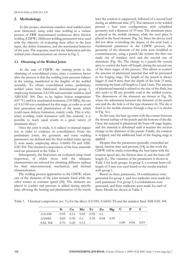
Fig. 5. Voids in the welded joint AA1100/SAE 304 in: a) sample 1-1 (3 mm, 5 s, and 835 rpm) and b) sample 1-13 (5 mm, 10 s, and 835 rpm). Flash in: c) sample 1-1 (3 mm, 5 s, and 835 rpm), d) sample 1-3 (3 mm, 5 s, and 2000 rpm), e) sample 1-16 (5 mm, 5 s, and 835 rpm), and f) sample 1-18 (5 mm, 15 s, and 2000 rpm).
The effect of rotational speed and friction time in the plasticity and fluidity of the material its evident when the quantity of flash is evaluated, as it is shown in Fig. 5c-f. The welded joints made with a high heat input (high rotational speed and friction time) present higher formation of flash without voids, according to the data presented by Seli et al. [39], who achieved to relate the maximum temperature reached in the surface with the formation of flash. Other authors such as Rafi et al. [40] asseverate that the adequate quantity of flash is a sign of an appropriate heat generation, promoting enough plastic deformation to prevent voids in the joint, as well as oxides and pollutants in the contact surfaces. Parameters of higher heat input, besides its present’s high formation of flash, not reported voids inside the welded joint (Fig. 5e-f).
It is clear that high rotation speeds favor the increase in the quantity of flash due to a major quantity heat introduced in the system, which also increases the volume of plasticized material as well as its fluidity [41]. The relationship between the rotational speed and the heat input is presented by Li et al. [16], who stablish a mathematical approach Eq. (1). (1) where q is the heat value during the RFW, R is the piece radius, μ is the friction coefficient, PN is the axial pressure applied and ω as the rotational speed.
However, also Li et al. [16], stand out the appearance of two elements regarding the temperature in the contact surface and the flash shape: 1) experimentally, the maximum temperature in the interface is generated between 1/2>R>2/3; 2) the axial load affects the form of the flash and the plasticized zone of the joint. It is in this point where the influence of the friction time is important because despite of having no evidence of its effect in the preliminary joints, Uday et al. [15] emphasize the importance of this variable in the thermal stabilization in the interface because as is indicated before, the temperature variates in radial direction, which generates different conditions of plasticized material. Thus, with an
increase in the friction time, the higher temperature homogenizes a major volume of material, increasing the possibility to plasticize more material, growing the size of the flash (Fig. 5d-f).
3.2. Final Welded Joints (“Group 2”)
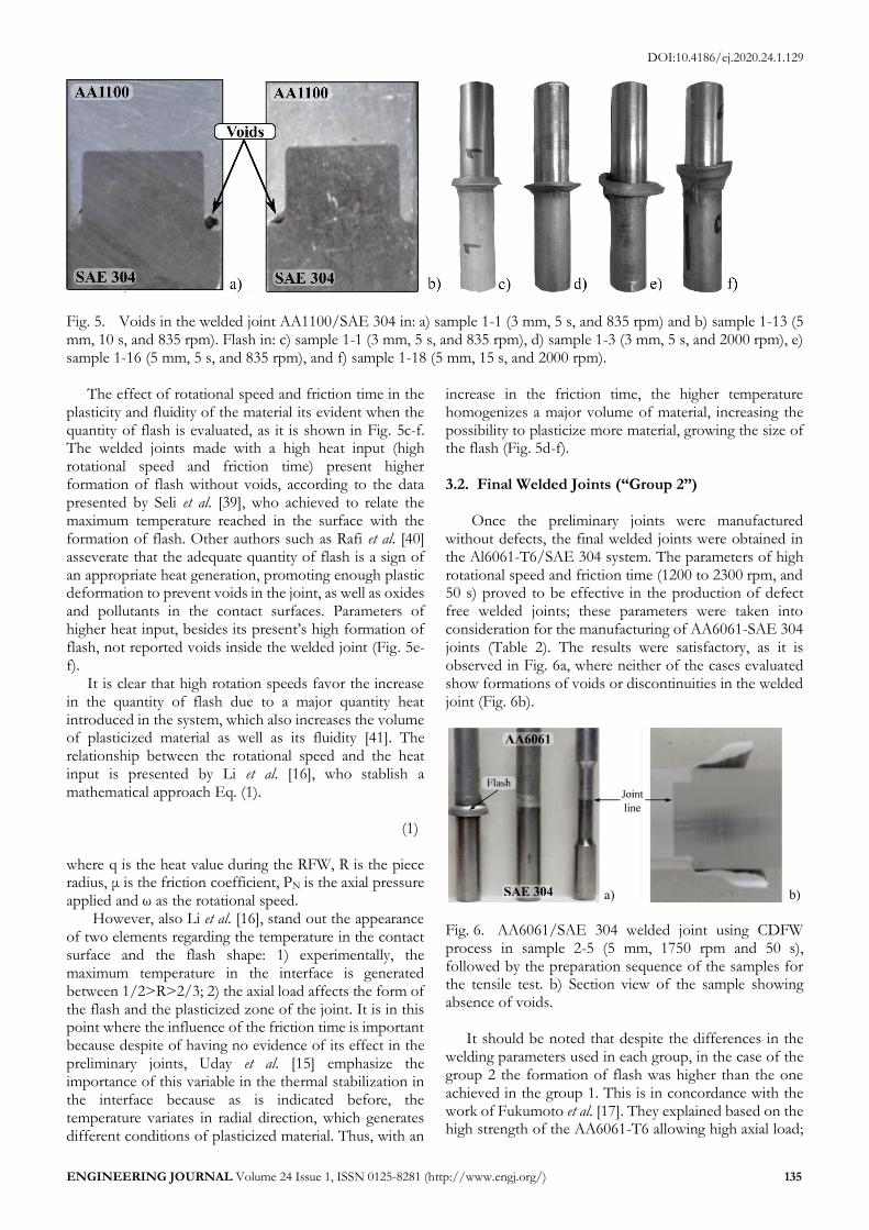
Once the preliminary joints were manufactured without defects, the final welded joints were obtained in the Al6061-T6/SAE 304 system. The parameters of high rotational speed and friction time (1200 to 2300 rpm, and 50 s) proved to be effective in the production of defect free welded joints; these parameters were taken into consideration for the manufacturing of AA6061-SAE 304 joints (Table 2). The results were satisfactory, as it is observed in Fig. 6a, where neither of the cases evaluated show formations of voids or discontinuities in the welded joint (Fig. 6b).
Fig. 6. AA6061/SAE 304 welded joint using CDFW process in sample 2-5 (5 mm, 1750 rpm and 50 s), followed by the preparation sequence of the samples for the tensile test. b) Section view of the sample showing absence of voids.
It should be noted that despite the differences in the
welding parameters used in each group, in the case of the group 2 the formation of flash was higher than the one achieved in the group 1. This is in concordance with the work of Fukumoto et al. [17]. They explained based on the high strength of the AA6061-T6 allowing high axial load;

DOI:10.4186/ej.2020.24.1.129
136 ENGINEERING JOURNAL Volume 24 Issue 1, ISSN 0125-8281 (http://www.engj.org/)
therefore, increases in heat generation rate resulting in a temperature increase. 3.3. Microstructural Characterization
On the other hand, the evaluation using OM did not allow identifying the formation of IMC (Fig. 7), in any of the welding groups or parameters evaluated. The joints agree in the formation of the two typical regions [16]: weld center zone (WCZ), and thermo-mechanically affected zone (TMAZ). The WCZ is characterized by the refinement of the grain due to the continuous dynamic recrystallization (CDRX) of the aluminum, because of the high deformation of the material at high temperature [42], [43]. The TMAZ corresponds to the zone characterized by the deformation bands showing geometric dynamic recrystallization (GDRX) in the most deformed grains near to the WCZ [42], [44], [45]. The heat affected zone (HAZ) could not be characterized using OM since the effects of temperature, mainly in the AA6061-T6, are measurable using micro-indentation due to the effect of the over-aging of the Mg2Si precipitates [46], [47]. The absence of IMC in both cases, contrast with the reports presented by different authors, even though these exists
discrepancies regarding to the type of compound. While authors like Aritoshi & Okita [48], and Muralimohan et al. [49] remark the exclusive formation of Fe2Al5, on the other hand Seli et al. [39] argue the presence of FeAl3. Otherwise, Fukumoto et al. [17] reports the formation of both IMC, likewise Kawai et al. [50] describe the presence of IMC, but without specify its nature.
Due to evidences shown previously, other observations were conducted using SEM, which confirm the absence on IMC in the welded joints (Fig. 8). One of the possible causes of the no formation of the IMC would be the continuous erosion of the surface of the SAE 304 due to the plasticized aluminum, which can prevent the nucleation and growth of the IMCs. The surface abrasion in both systems is significant, as it is proved by Rao & Hazlett [51]. However, Wei et al. [52] ruled out this possibility in Al-Cu joints, using FRW welded process, suggesting that the nucleation and growth of the IMCs (Al2Cu and Al4Cu9) is produced by the rapid interdiffusion of the species during the forge stage, in which the rotation is suspended, be given that the diffusion coefficient is three and seven times higher than those reported in literature and determined under thermal equilibrium.
Fig. 7. Micrograph using OM for the welded joint interface by FRW. a) Welded joint AA1100/SAE 304, sample 1-11 (5 mm, 5 s and 1320 rpm) observing at the interface, the WCZ and the TMAZ; b) detail of the interface in the joint AA6061/SAE 304, of the sample 2-5 (5 mm, 50 s and 1750 rpm).
Fig. 8. SEM micrographs of the interface for joints AA6061-SAE304, sample 2-2 (5 mm, 15 s, 1750 rpm), close to the middle part of the sample radium, near half of the sample radium. Etching with fluoridric acid at 1%.

DOI:10.4186/ej.2020.24.1.129
ENGINEERING JOURNAL Volume 24 Issue 1, ISSN 0125-8281 (http://www.engj.org/) 137
The absence of IMC in this kind of welded systems is also confirmed by Chernenko [53], who attributes this condition to the low temperatures reached during the process (360-450 °C), despite of noting the formation of a reaction layer in the welded interface. Lee at al. [54] highlighted how this reaction layer increases in a proportional way with the friction time, increasing in the boundaries of the interface. Meshram et al. [55] agree with the statement that not always IMCs are formed in dissimilar systems but the presence of atomic interdiffusion along the interface form the reaction layer. The results of temperature measures in the joints to evaluate the effect of temperature in the absence of IMCs in the welded joints using CDFW are shown in Fig. 9a; the average temperature values recorded in the thermocouple vary from 243 a 521 ºC, being 544 ºC the maximum recorded in the third repetition of the sample 2-5.
The simulation was analyzed using friction times from 15 to 50 s to obtain results such as the one shown in Fig. 4b, standing out a temperature of 558 ºC in the interface, while for the thermocouple was 544 ºC, the highest recorded value in the experimental measures. The simulation results show that the temperature in the interface vary from 249 to 534 ºC, with a maximum of 558 ºC. These values are higher than those observed by Alves et al. [56], who developed welded joints using IFW between AA1050 and AISI 304 and determined temperatures from 370 °C to 430 °C at 0.2 mm from the interface.
From the analysis of the results, it can be observed how the low rotational speed and the friction time affect
directly the temperature in the joint, whereas to reach high temperatures, the influence variable is the speed. It is normal that the temperature increases with the rotation speed, but it is also normal that temperature decreases at high rotation speeds, since sliding velocity is reached under these circumstances, and the friction coefficient between surfaces reduces significantly, reducing as well the heat quantity and the maximum temperature at the interface [14]. This can be seen in Fig. 9 when comparing the temperature reached between samples 2-5 and 2-6 (1750 and 2300 rpm, at a friction time of 50 s), where temperature decreases due to the high plasticization of the metal, which entails a reduction in the friction coefficient and limits the temperature rise. Besides, as pointed out by Alves et al. [57], the drastic rise in the temperature happens during the first 10 s of friction and additional time is not relevant in heat generation.
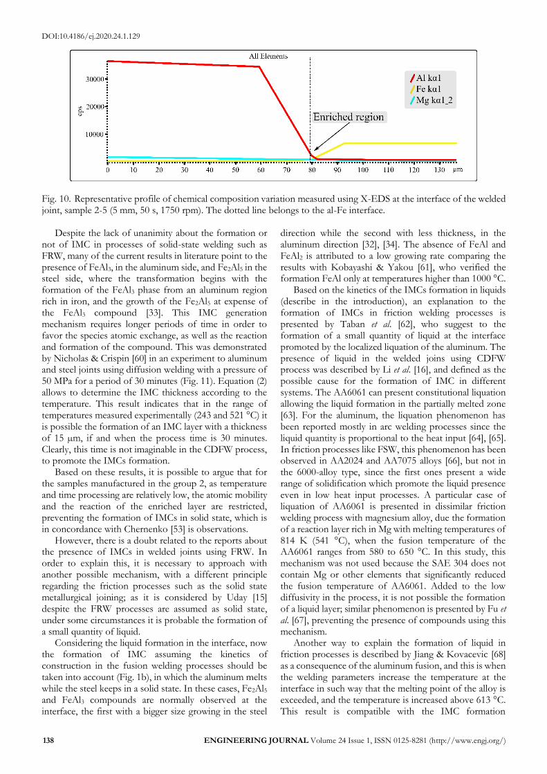
As in solid state the kinetics in the formation of IMCs involves the growth of a supersaturate region, due to the atoms migration, and the transformation of that region into IMC, when there are differences between the diffusivity of the species, like in the Fe-Al system, the growth is favorable in the aluminum side, because the mobility of the Fe over the Al is better than in the opposite case. This effect is clearer in the X-EDS results (Fig. 10), in which there is no IMC formation but there is presence of a minimum region of Al with traces of Fe. The presence of IMCs in the diffractogram is clearly shown by the steps in the curve, as seen in the results provided by Pourali et al. [58] and Hincapié et al. [59], contrary to the constant drop in the Fe and Al composition shown in the interface.
Fig. 9. Results in the temperature measure in welded joints in the group 2 using CDFW, with burn-off length of 5 mm, and different parameters of rotation speed and friction time.
DOI:10.4186/ej.2020.24.1.129
138 ENGINEERING JOURNAL Volume 24 Issue 1, ISSN 0125-8281 (http://www.engj.org/)
Fig. 10. Representative profile of chemical composition variation measured using X-EDS at the interface of the welded joint, sample 2-5 (5 mm, 50 s, 1750 rpm). The dotted line belongs to the al-Fe interface.
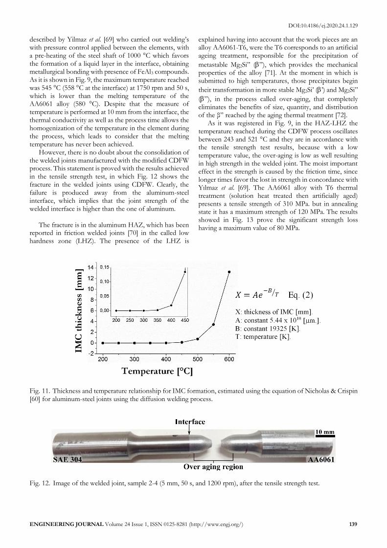
Despite the lack of unanimity about the formation or not of IMC in processes of solid-state welding such as FRW, many of the current results in literature point to the presence of FeAl3, in the aluminum side, and Fe2Al5 in the steel side, where the transformation begins with the formation of the FeAl3 phase from an aluminum region rich in iron, and the growth of the Fe2Al5 at expense of the FeAl3 compound [33]. This IMC generation mechanism requires longer periods of time in order to favor the species atomic exchange, as well as the reaction and formation of the compound. This was demonstrated by Nicholas & Crispin [60] in an experiment to aluminum and steel joints using diffusion welding with a pressure of 50 MPa for a period of 30 minutes (Fig. 11). Equation (2) allows to determine the IMC thickness according to the temperature. This result indicates that in the range of temperatures measured experimentally (243 and 521 °C) it is possible the formation of an IMC layer with a thickness of 15 µm, if and when the process time is 30 minutes. Clearly, this time is not imaginable in the CDFW process, to promote the IMCs formation.
Based on these results, it is possible to argue that for the samples manufactured in the group 2, as temperature and time processing are relatively low, the atomic mobility and the reaction of the enriched layer are restricted, preventing the formation of IMCs in solid state, which is in concordance with Chernenko [53] is observations.
However, there is a doubt related to the reports about the presence of IMCs in welded joints using FRW. In order to explain this, it is necessary to approach with another possible mechanism, with a different principle regarding the friction processes such as the solid state metallurgical joining; as it is considered by Uday [15] despite the FRW processes are assumed as solid state, under some circumstances it is probable the formation of a small quantity of liquid.
Considering the liquid formation in the interface, now the formation of IMC assuming the kinetics of construction in the fusion welding processes should be taken into account (Fig. 1b), in which the aluminum melts while the steel keeps in a solid state. In these cases, Fe2Al5 and FeAl3 compounds are normally observed at the interface, the first with a bigger size growing in the steel
direction while the second with less thickness, in the aluminum direction [32], [34]. The absence of FeAl and FeAl2 is attributed to a low growing rate comparing the results with Kobayashi & Yakou [61], who verified the formation FeAl only at temperatures higher than 1000 °C.
Based on the kinetics of the IMCs formation in liquids (describe in the introduction), an explanation to the formation of IMCs in friction welding processes is presented by Taban et al. [62], who suggest to the formation of a small quantity of liquid at the interface promoted by the localized liquation of the aluminum. The presence of liquid in the welded joins using CDFW process was described by Li et al. [16], and defined as the possible cause for the formation of IMC in different systems. The AA6061 can present constitutional liquation allowing the liquid formation in the partially melted zone [63]. For the aluminum, the liquation phenomenon has been reported mostly in arc welding processes since the liquid quantity is proportional to the heat input [64], [65]. In friction processes like FSW, this phenomenon has been observed in AA2024 and AA7075 alloys [66], but not in the 6000-alloy type, since the first ones present a wide range of solidification which promote the liquid presence even in low heat input processes. A particular case of liquation of AA6061 is presented in dissimilar friction welding process with magnesium alloy, due the formation of a reaction layer rich in Mg with melting temperatures of 814 K (541 °C), when the fusion temperature of the AA6061 ranges from 580 to 650 °C. In this study, this mechanism was not used because the SAE 304 does not contain Mg or other elements that significantly reduced the fusion temperature of AA6061. Added to the low diffusivity in the process, it is not possible the formation of a liquid layer; similar phenomenon is presented by Fu et al. [67], preventing the presence of compounds using this mechanism.
Another way to explain the formation of liquid in friction processes is described by Jiang & Kovacevic [68] as a consequence of the aluminum fusion, and this is when the welding parameters increase the temperature at the interface in such way that the melting point of the alloy is exceeded, and the temperature is increased above 613 °C. This result is compatible with the IMC formation
DOI:10.4186/ej.2020.24.1.129
ENGINEERING JOURNAL Volume 24 Issue 1, ISSN 0125-8281 (http://www.engj.org/) 139
described by Yilmaz et al. [69] who carried out welding’s with pressure control applied between the elements, with a pre-heating of the steel shaft of 1000 °C which favors the formation of a liquid layer in the interface, obtaining metallurgical bonding with presence of FeAl3 compounds. As it is shown in Fig. 9, the maximum temperature reached was 545 °C (558 °C at the interface) at 1750 rpm and 50 s, which is lower than the melting temperature of the AA6061 alloy (580 °C). Despite that the measure of temperature is performed at 10 mm from the interface, the thermal conductivity as well as the process time allows the homogenization of the temperature in the element during the process, which leads to consider that the melting temperature has never been achieved.
However, there is no doubt about the consolidation of the welded joints manufactured with the modified CDFW process. This statement is proved with the results achieved in the tensile strength test, in which Fig. 12 shows the fracture in the welded joints using CDFW. Clearly, the failure is produced away from the aluminum-steel interface, which implies that the joint strength of the welded interface is higher than the one of aluminum.
The fracture is in the aluminum HAZ, which has been reported in friction welded joints [70] in the called low hardness zone (LHZ). The presence of the LHZ is
explained having into account that the work pieces are an alloy AA6061-T6, were the T6 corresponds to an artificial ageing treatment, responsible for the precipitation of
metastable Mg2Si” (”), which provides the mechanical properties of the alloy [71]. At the moment in which is submitted to high temperatures, those precipitates begin
their transformation in more stable Mg2Si’ (’) and Mg2Si”
(”), in the process called over-aging, that completely eliminates the benefits of size, quantity, and distribution of the β” reached by the aging thermal treatment [72].
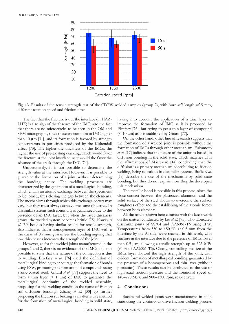
As it was registered in Fig. 9, in the HAZ-LHZ the temperature reached during the CDFW process oscillates between 243 and 521 °C and they are in accordance with the tensile strength test results, because with a low temperature value, the over-aging is low as well resulting in high strength in the welded joint. The moist important effect in the strength is caused by the friction time, since longer times favor the lost in strength in concordance with Yılmaz et al. [69]. The AA6061 alloy with T6 thermal treatment (solution heat treated then artificially aged) presents a tensile strength of 310 MPa. but in annealing state it has a maximum strength of 120 MPa. The results showed in Fig. 13 prove the significant strength loss having a maximum value of 80 MPa.
Fig. 11. Thickness and temperature relationship for IMC formation, estimated using the equation of Nicholas & Crispin [60] for aluminum-steel joints using the diffusion welding process.
Fig. 12. Image of the welded joint, sample 2-4 (5 mm, 50 s, and 1200 rpm), after the tensile strength test.
DOI:10.4186/ej.2020.24.1.129
140 ENGINEERING JOURNAL Volume 24 Issue 1, ISSN 0125-8281 (http://www.engj.org/)
Fig. 13. Results of the tensile strength test of the CDFW welded samples (group 2), with burn-off length of 5 mm, different rotation speed and friction time.
The fact that the fracture is out the interface (in HAZ-LHZ) is also sign of the absence of the IMC, also the fact that there are no microcracks to be seen in the OM and SEM micrographs, since these are common in IMC higher
than 10 m [31], and its formation is favored by strength concentrators in porosities produced by the Kirkendall effect [73]. The higher the thickness of the IMCs, the higher the risk of pre-existing cracking, which would favor the fracture at the joint interface, as it would the favor the advance of the crack through the IMC [74].
Unfortunately, it is not possible to determine the strength value at the interface. However, it is possible to guarantee the formation of a joint, without determining the bonding nature. The welding processes are characterized by the generation of a metallurgical bonding, which entails an atomic exchange between the specimens to be joined, thus closing the gap between the elements. The mechanisms through which this exchange occurs may vary, but they must always achieve the same objective. In dissimilar systems such continuity is guaranteed due to the presence of an IMC layer, but when the layer thickness grows, the welded system becomes brittle [75]. Kaway et al. [50] besides having similar results for tensile strength, also indicates that a homogeneous layer of IMC with a thickness of 0.2 mm guarantees the bonding arguing that low thicknesses increases the strength of the joint.
However, as for the welded joints manufactured in the groups 1 and 2, there is no evidence of the IMCs, it is not possible to state that the nature of the connection is due to welding. Elrefaey et al. [76] used the definition of metallurgical binding to encourage the formation of bonds using FSW, promoting the formation of compounds using a zinc-coated steel. Girard et al. [77] support the need to form a thin layer (< 1 µm) of IMC to guarantee the metallurgical continuity of the welded assembly, proposing for this welding condition the name of friction stir diffusion bonding. Zhang et al. [30] go further proposing the friction stir brazing as an alternative method for the formation of metallurgical bonding in solid state,
having into account the application of a zinc layer to improve the formation of IMC as it is proposed by Elrefaey [76], but trying to get a thin layer of compound (< 10 µm) as it is stablished by Girard [77].
On the other hand, other line of research suggests that the formation of a welded joint is possible without the formation of IMCs through other mechanism. Fukumoto et al. [17] indicate that the nature of the union is based on diffusion bonding in the solid state, which matches with the affirmations of Maalekian [14] concluding that the diffusion is a primary mechanism contributing to friction welding, being notorious in dissimilar systems. Buffa et al. [78] describe the use of the mechanism by solid state bonding, but they do not explain how they the developed this mechanism.
The metallic bond is possible in this process, since the close contact between the plasticized aluminum and the solid surface of the steel allows to overcome the surface roughness effect and the establishing of the atomic forces between both elements.
All the results shown here contrast with the latest work on the matter, conducted by Liu et al. [75], who fabricated dissimilar joints of SS304 and AA6061-T6 using IFW. Temperatures from 350 to 450 ºC, at 0.5 mm from the interface by the Al side, were reached in this work, with fracture in the interface due to the presence of IMCs lower
than 0.5 m, allowing a tensile strength up to 323 MPa (94 % of AA6061-T6). Clearly, controlling the size of the IMCs layer allowed the high strength of the joint, with evident formation of metallurgical bonding, guaranteed by the presence of a homogeneous and thin layer (without porosities). These results can be attributed to the use of high axial friction pressure and the rotational speed of 140–220 MPa, and 900–1500 rpm, respectively.
4. Conclusions
Successful welded joints were manufactured in solid state using the continuous drive friction welding process

DOI:10.4186/ej.2020.24.1.129
ENGINEERING JOURNAL Volume 24 Issue 1, ISSN 0125-8281 (http://www.engj.org/) 141
in dissimilar AA1100/SAE304 and AA6061-T6/SAE304 systems. In both systems, consolidated welded joints (defect free) obtain without the presence of intermetallic compounds were verified.
The observed defects in the preliminary joints are caused by voids, generated due to geometrical changes in the welded system as well as the low fluidity of the plasticized metal, which is related to the quantity of flash in the joint. The fluidity and quantity of flash directly depends of the heat input controlled by the rotation speed. Low rotation speed generates low heat input and results in the low fluidity of the plasticized metal, the void formation and the low flash generation. The friction time allows a homogeneous temperature which results in a better quantity of plasticized metal.
The absence of IMC is due to the low heat input generated in this process, which reduces the maximum temperature reached (545 °C) and inhibits the compound formation in two ways: i) considering the solid state, the low diffusivity prevent the formation of a reactive layer due to the accumulation of Fe in the aluminum and also prevent the FeAl3 formation; and ii) suppressing the partial liquid formation, since the temperature at the interface never reaches the melting temperature of the aluminum or because to the absence of liquation because the low heat input does not affect the AA6061 alloy.
The behavior of the welded joints results adequate, since the totality of the joints fails at the thermomechanical affected zone in the so-called low hardness zone, as a result of the over aging of the Mg2Si”
(”). The strength of the joint at the interface is
unquestionable, thanks to the results of mechanical tests. However, the absence of IMC puts into question the metallurgical character of the welded joint. The nature of the mechanism presents in the joint at the interface remains unclear, but it is considered that the atomic exchange through the interface or diffusion bonding favors the formation of a stable and stronger bond. The metallic bond is possible thanks to the close contact between the plasticized aluminum and the solid surface of the steel, producing the stablishing of the atomic forces between both elements.
Acknowledgements This work was possible thanks to the contributions of
several people and groups to which we will refer. The metallography laboratory of the Universidad de Antioquia, for allowing the use of its facilities for metallographic preparation and hardness measurements by micro-indentation. We extend our gratitude to the GIPIME group of the Universidad de Antioquia for allowing the use of the optical microscope. Finally, to the Instituto Tecnológico Metropolitano (ITM), for allowing us to carry out the characterization by SEM and X-EDS in its electron microscopy laboratory, as well as for allowing the manufacture of solid-state welds in its machine tools workshop.
References [1] R. Samel, “Materials in cars: Options for change,”
Mater. Technol., vol. 16, no. 1, pp. 4–7, 2001. [2] K. Martinsen, S. J. Hu, and B. E. Carlson, “Joining
of dissimilar materials,” CIRP Ann. - Manuf. Technol., vol. 64, no. 2, pp. 679–699, 2015.
[3] Y. C. Chen, A. Gholinia, and P. B. Prangnell, “Interface structure and bonding in abrasion circle friction stir spot welding: A novel approach for rapid welding aluminium alloy to steel automotive sheet,” Mater. Chem. Phys., vol. 134, no. 1, pp. 459–463, May 2012.
[4] M. Schimek, A. Springer, S. Kaierle, D. Kracht, and V. Wesling, “Laser-welded Dissimilar Steel-aluminum Seams for Automotive Lightweight Construction,” Phys. Procedia, vol. 39, pp. 43–50, Jan. 2012.
[5] T. Sakiyama, G. Murayama, Y. Naito, K. Saita, Y. Miyazaki, H. Oikawa, and T. Nose, “Dissimilar metal joining technologies for steel sheet and aluminum alloy sheet in auto body,” Nippon Steel Tech. Rep., vol. 103, pp. 91–98, 2013.
[6] M. Sahin, “Joining of stainless-steel and aluminium materials by friction welding,” Int. J. Adv. Manuf. Technol., vol. 41, no. 5–6, pp. 487–497, 2009.
[7] S. Su, S. Chen, Y. Mao, J. Xiao, A. Vivek, and G. Daehn, “Joining aluminium alloy 5A06 to stainless steel 321 by vaporizing foil actuators welding with an interlayer,” Metals (Basel)., vol. 9, no. 1, 2019.
[8] T. Newson, Stainless Steel-Applications, Grades and Human Exposure. AvestaPolarit Oyj Abp, 2001.
[9] H. Ishimaru, “Developments and Applications for All-Aluminum Alloy Vacuum Systems,” MRS Bull., vol. 15, no. 7, pp. 23–31, Jul. 1990.
[10] S. Tomida and K. Nakata, “Fe–Al composite layers on aluminum alloy formed by laser surface alloying with iron powder,” Surf. Coatings Technol., vol. 174–175, pp. 559–563, Sep. 2003.
[11] R. Borrisutthekul, A. Seangsai, and W. Paonil, “GTAW of zinc-coated steel and aluminum alloy,” Eng. J., vol. 22, no. 3, pp. 39–49, 2018.
[12] C. M. Chen and R. Kovacevic, “Joining of Al 6061 alloy to AISI 1018 steel by combined effects of fusion and solid state welding,” Int. J. Mach. Tools Manuf., vol. 44, no. 11, pp. 1205–1214, 2004.
[13] S. Chainarong, C. Meengam, and M. Tehyo, “Rotary friction welding of dissimilar joints between SSM356 and SSM6061 aluminium alloys produced by GISS,” Eng. J., vol. 21, no. 1, pp. 181–191, Jan. 2017.
[14] M. Maalekian, “Friction welding – Critical assessment of literature,” Sci. Technol. Weld. Join., vol. 12, no. 8, pp. 738–759, Nov. 2007.
[15] M. B. Uday, M. N. Ahmad Fauzi, H. Zuhailawati, and A. B. Ismail, “Advances in friction welding process: a review,” Sci. Technol. Weld. Join., vol. 15, no. 7, pp. 534–558, Oct. 2010.
[16] W. Li, A. Vairis, M. Preuss, and T. Ma, “Linear and rotary friction welding review,” Int. Mater. Rev., vol.
DOI:10.4186/ej.2020.24.1.129
142 ENGINEERING JOURNAL Volume 24 Issue 1, ISSN 0125-8281 (http://www.engj.org/)
61, no. 2, pp. 71–100, Feb. 2016. [17] S. Fukumoto, H. Tsubakino, K. Okita, M. Aritoshi,
and T. Tomita, “Friction welding process of 5052 aluminium alloy to 304 stainless steel,” Mater. Sci. Technol., vol. 15, no. 9, pp. 1080–1086, Sep. 1999.
[18] A. Kankanala, S. Kotturu, R. Mylarusetty, and S. Afroz, “Weldability of aluminum to mild steel using friction welding process,” Int. J. Adv. Eng. Res. Sci., vol. 3, no. 10, pp. 206–210, 2016.
[19] V. Soundararajan and K. Radovan, “Friction stir welding of steel to aluminum alloy,” in 6th International Symposium on Friction Stir Weldin, The Welding Institute, Ltd, 2006, pp. 829–839.
[20] T. Tanaka, T. Morishige, and T. Hirata, “Comprehensive analysis of joint strength for dissimilar friction stir welds of mild steel to aluminum alloys,” Scr. Mater., vol. 61, no. 7, pp. 756–759, 2009.
[21] M. Fukumoto, T. Yasui, Y. Shimoda, M. Tsubaki, and T. Shinoda, “Butt welding between dissimilar metals by friction stirring,” in 5th International Friction Stir Welding Symposium, The Welding Institute, Ltd, 2004, p. 32.
[22] T. Chen, “Process parameters study on FSW joint of dissimilar metals for aluminum–steel,” J. Mater. Sci., vol. 44, no. 10, pp. 2573–2580, May 2009.
[23] T. P. Chen and W.-B. Lin, “Optimal FSW process parameters for interface and welded zone toughness of dissimilar aluminium–steel joint,” Sci. Technol. Weld. Join., vol. 15, no. 4, pp. 279–285, May 2010.
[24] S. Sitthipong, P. Towatana, C. Meengam, S. Chainarong, and P. Muangjunburee, “The influence of parameters affecting mechanical properties and microstructures of semi-solid-metal 7075 aluminum alloy by using friction stir spot welding,” Eng. J., vol. 22, no. 3, pp. 51–64, 2018.
[25] E. A. T. López and A. J. Ramirez, “Effect of process parameters in obtaining aluminium–steel joints and their microstructure by friction stir welding (FSW),” Weld. Int., vol. 29, no. 9, pp. 689–697, Sep. 2015.
[26] E. Torres and A. Ramirez, “Inhibición de la formación de compuestos intermetálicos en juntas aluminio-acero soldadas por fricción-agitación,” Rev. Metal., vol. 52, no. 1, pp. 3–11, 2016.
[27] Y. C. Chen and K. Nakata, “Effect of the surface state of steel on the microstructure and mechanical properties of dissimilar metal lap joints of aluminum and steel by friction stir welding,” Metall. Mater. Trans. A Phys. Metall. Mater. Sci., vol. 39, no. 8, pp. 1985–1992, 2008.
[28] Y. C. Chen, T. Komazaki, Y. G. Kim, T. Tsumura, and K. Nakata, “Interface microstructure study of friction stir lap joint of AC4C cast aluminum alloy and zinc-coated steel,” Mater. Chem. Phys., vol. 111, no. 2–3, pp. 375–380, 2008.
[29] P. Xue, B. L. Xiao, D. R. Ni, and Z. Y. Ma, “Enhanced mechanical properties of friction stir welded dissimilar Al-Cu joint by intermetallic compounds,” Mater. Sci. Eng. A, vol. 527, no. 21–22,
pp. 5723–5727, 2010. [30] G. Zhang, W. Su, J. Zhang, and Z. Wei, “Friction stir
brazing: A novel process for fabricating Al/steel layered composite and for dissimilar joining of Al to steel,” Metall. Mater. Trans. A, vol. 42, no. 9, pp. 2850–2862, 2011.
[31] Q. Wang, X. Leng, T. Yang, and J. Yan, “Effects of Fe—Al intermetallic compounds on interfacial bonding of clad materials,” Trans. Nonferrous Met. Soc. China, vol. 24, no. 1, pp. 279–284, Jan. 2014.
[32] H. . Shahverdi, M. . Ghomashchi, S. Shabestari, and J. Hejazi, “Microstructural analysis of interfacial reaction between molten aluminium and solid iron,” J. Mater. Process. Technol., vol. 124, no. 3, pp. 345–352, Jun. 2002.
[33] M. J. Rathod and M. Kutsuna, “Joining of aluminum alloy 5052 and low-carbon steel by laser roll welding,” Weld. J., vol. 83, no. 1, pp. 16–26, 2004.
[34] K. Bouché, F. Barbier, and A. Coulet, “Intermetallic compound layer growth between solid iron and molten aluminium,” Mater. Sci. Eng. A, vol. 249, no. 1–2, pp. 167–175, 1998.
[35] L. Agudo, D. Eyidi, C. H. Schmaranzer, E. Arenholz, N. Jank, J. Bruckner, and A. R. Pyzalla, “Intermetallic Fe x Al y -phases in a steel/Al-alloy fusion weld,” J. Mater. Sci., vol. 42, no. 12, pp. 4205–4214, Jun. 2007.
[36] E. D. Nicholas, “Friction processing technologies,” Weld. World, vol. 47, no. 11–12, pp. 2–9, Nov. 2003.
[37] M. Şahin and H. E. Akata, “Joining with friction welding of plastically deformed steel,” J. Mater. Process. Technol., vol. 142, no. 1, pp. 239–246, Nov. 2003.
[38] A. Sahin, B. Yilbas, and A. Al-Garni, “Friction welding of Al-Al, Al-steel, and steel-steel samples,” J. Mater. Eng. Perform., vol. 5, no. 1, pp. 89–99, Feb. 1996.
[39] H. Seli, A. I. M. Ismail, E. Rachman, and Z. A. Ahmad, “Mechanical evaluation and thermal modelling of friction welding of mild steel and aluminium,” J. Mater. Process. Technol., vol. 210, no. 9, pp. 1209–1216, Jun. 2010.
[40] H. K. Rafi, G. D. J. Ram, G. Phanikumar, and K. P. Rao, “Microstructure and tensile properties of friction welded aluminum alloy AA7075-T6,” Mater. Des., vol. 31, no. 5, pp. 2375–2380, May 2010.
[41] F. Sassani and J. R. Neelam, “Friction welding of incompatible materials,” Weld. Res. Suppl., pp. 264s-270s, 1988.
[42] A. L. Etter, T. Baudin, N. Fredj, and R. Penelle, “Recrystallization mechanisms in 5251 H14 and 5251 O aluminum friction stir welds,” Mater. Sci. Eng. A, vol. 445–446, pp. 94–99, 2007.
[43] S. Mironov, Y. S. Sato, and H. Kokawa, “Applications of EBSD to microstructural control in friction stir welding/processing,” in Electron Backscatter Diffraction in Materials Science, Boston, MA: Springer US, 2009, pp. 291–300.
[44] R. D. Doherty, D.A. Hughes,, F.J. Humphreys,, J.J. Jonas,, D.J. Jensen,, M.E. Kassner,, W.E. King,, T.R. McNelley,, H.J. McQueen, and A.D. Rollett,,
DOI:10.4186/ej.2020.24.1.129
ENGINEERING JOURNAL Volume 24 Issue 1, ISSN 0125-8281 (http://www.engj.org/) 143
“Current issues in recrystallization: A review,” Mater. Sci. Eng. A, vol. 238, no. 2, pp. 219–274, Nov. 1997.
[45] F. J. Humphreys and M. Hatherly, Recrystallization and Related Annealing Phenomena. Elsevier, 2004.
[46] Y. S. Sato, H. Kokawa, M. Enomoto, and S. Jogan, “Microstructural evolution of 6063 aluminum during friction-stir welding,” Metall. Mater. Trans. A, vol. 30, no. 9, pp. 2429–2437, Sep. 1999.
[47] J. Zhang, Z. Fan, Y. Q. Wang, and B. L. Zhou, “Equilibrium pseudobinary Al–Mg2Si phase diagram,” Mater. Sci. Technol., vol. 17, no. 5, pp. 494–496, May 2001.
[48] M. Aritoshi and K. Okita, “Friction welding of dissimilar metals,” Weld. Int., vol. 17, no. 4, pp. 271–275, Jan. 2003.
[49] C. Muralimohan, S. Haribabu, Y. Hariprasada Reddy, V. Muthupandi, and K. Sivaprasad, “Joining of AISI 1040 steel to 6082-T6 aluminium alloy by friction welding,” J. Adv. Mech. Eng. Sci., vol. 1, no. 1, pp. 57–64, Aug. 2015.
[50] G. Kawai, K. Ogawa, H. Ochi, and H. Tokisue, “Friction weldability of aluminium alloys to carbon steel,” Weld. Int., vol. 14, no. 2, pp. 101–107, Jan. 2000.
[51] M. Rao and T. Hazlett, “A study of the mechanisms involved in friction welding of aluminum alloys,” Weld. Res. Suppl., vol. 14, no. 2, pp. 181s-188s, 1970.
[52] Y. Wei, J. Li, J. Xiong, and F. Zhang, “Investigation of interdiffusion and intermetallic compounds in Al–Cu joint produced by continuous drive friction welding,” Eng. Sci. Technol. an Int. J., vol. 19, no. 1, pp. 90–95, Mar. 2016.
[53] I. A. Chernenko, “Friction welding AD1 aluminium to 12Kh18N10T steel,” Weld. Int., vol. 3, no. 7, pp. 586–590, Jan. 1989.
[54] W. B. Lee, Y. M. Yeon, D. U. Kim, and S. B. Jung, “Effect of friction welding parameters on mechanical and metallurgical properties of aluminium alloy 5052–A36 steel joint,” Mater. Sci. Technol., vol. 19, no. 6, pp. 773–778, Jun. 2003.
[55] S. D. Meshram, T. Mohandas, and G. M. Reddy, “Friction welding of dissimilar pure metals,” J. Mater. Process. Technol., vol. 184, no. 1–3, pp. 330–337, Apr. 2007.
[56] E. P. Alves, F. Piorino Neto, and C. Y. An, “Welding of AA1050 aluminum with AISI 304 stainless steel by rotary friction welding process,” J. Aerosp. Technol. Manag., vol. 2, no. 3, pp. 301–306, 2010.
[57] E. P. Alves, F. Piorino Neto, C. Y. An, and E. C. da Silva, “Experimental determination of temperature during rotary friction welding of AA1050 aluminum with AISI 304 stainless steel,” J. Aerosp. Technol. Manag., vol. 4, no. 1, pp. 61–68, 2012.
[58] M. Pourali, A. Abdollah-zadeh, T. Saeid, and F. Kargar, “Influence of welding parameters on intermetallic compounds formation in dissimilar steel/aluminum friction stir welds,” J. Alloys Compd., vol. 715, pp. 1–8, Aug. 2017.
[59] O. D. Hincapié, J. A. Salazar, J. J. Restrepo, E. A.
Torres, and J. Graciano-Uribe, “Control of formation of intermetallic compound in dissimilar joints aluminum-steel,” Int. J. Eng. - Trans. A Basics, vol. 32, no. 1, pp. 127–136, 2019.
[60] M. G. Nicholas and R. M. Crispin, “Diffusion bonding stainless steel to alumina using aluminium interlayers,” J. Mater. Sci., vol. 17, no. 11, pp. 3347–3360, Nov. 1982.
[61] S. Kobayashi and T. Yakou, “Control of intermetallic compound layers at interface between steel and aluminum by diffusion-treatment,” Mater. Sci. Eng. A, vol. 338, no. 1–2, pp. 44–53, Dec. 2002.
[62] E. Taban, J. E. Gould, and J. C. Lippold, “Dissimilar friction welding of 6061-T6 aluminum and AISI 1018 steel: Properties and microstructural characterization,” Mater. Des., vol. 31, no. 5, pp. 2305–2311, May 2010.
[63] M. Miyazaki, K. Nishio, M. Katoh, S. Mukae, and H. W. Kerr, “Quantitative investigation of heat affected zone cracking of aluminium alloy 6061,” Weld. Int., vol. 4, no. 8, pp. 600–609, Jan. 1990.
[64] S. Kou, “Solidification and liquation cracking issues in welding,” JOM, vol. 55, no. 6, pp. 37–42, Jun. 2003.
[65] C. Huang and S. Kou, “Liquation cracking in full-penetration Al-Mg-Si Welds,” Suppl. to Weld. J., pp. 111S-122S, 2004.
[66] A. P. Gerlich and T. Shibayanagi, “Liquid film formation and cracking during friction stir welding,” Sci. Technol. Weld. Join., vol. 16, no. 4, pp. 295–299, 2011.
[67] B. Fu, G. Qin, F. Li, X. Meng, J. Zhang, and C. Wu, “Friction stir welding process of dissimilar metals of 6061-T6 aluminum alloy to AZ31B magnesium alloy,” J. Mater. Process. Technol., vol. 218, pp. 38–47, Apr. 2015.
[68] W. H. Jiang and R. Kovacevic, “Feasibility study of friction stir welding of 6061-T6 aluminium alloy with AISI 1018 steel,” Proc. Inst. Mech. Eng. Part B J. Eng. Manuf., vol. 218, no. 10, pp. 1323–1331, Oct. 2004.
[69] M. Yilmaz, M. Çöl, and M. Acet, “Interface properties of aluminum/steel friction-welded components,” Mater. Charact., vol. 49, no. 5, pp. 421–429, 2002.
[70] F. C. Liu and Z. Y. Ma, “Influence of tool dimension and welding parameters on microstructure and mechanical properties of friction-stir-welded 6061-T651 aluminum alloy,” Metall. Mater. Trans. A, vol. 39, no. 10, pp. 2378–2388, Oct. 2008.
[71] B. Heinz and B. Skrotzki, “Characterization of a friction-stir-welded aluminum alloy 6013,” Metall. Mater. Trans. B, vol. 33, no. 3, pp. 489–498, Jun. 2002.
[72] G. A. Edwards, K. Stiller, G. L. Dunlop, and M. J. Couper, “The precipitation sequence in Al–Mg–Si alloys,” Acta Mater., vol. 46, no. 11, pp. 3893–3904, Jul. 1998.
[73] H. Springer, A. Kostka, J. F. dos Santos, and D. Raabe, “Influence of intermetallic phases and Kirkendall-porosity on the mechanical properties of joints between steel and aluminium alloys,” Mater. Sci.

DOI:10.4186/ej.2020.24.1.129
144 ENGINEERING JOURNAL Volume 24 Issue 1, ISSN 0125-8281 (http://www.engj.org/)
Eng. A, vol. 528, no. 13–14, pp. 4630–4642, May 2011.
[74] H. Springer, A. Kostka, E. J. Payton, D. Raabe, A. Kaysser-Pyzalla, and G. Eggeler, “On the formation and growth of intermetallic phases during interdiffusion between low-carbon steel and aluminum alloys,” Acta Mater., vol. 59, no. 4, pp. 1586–1600, Feb. 2011.
[75] Y. Liu, H. Zhao, Y. Peng, and X. Ma, “Mechanical properties of the inertia friction welded aluminum/stainless steel joint,” Weld. World, vol. 63, no. 6, pp. 1601–1611, Nov. 2019.
[76] A. Elrefaey, M. Takahashi, and K. Ikeuchi, “Friction-stir-welded lap joint of aluminum to zinc-coated steel,” Q. J. Japan Weld. Soc., vol. 23, no. 2, pp. 186–193, 2006.
[77] M. Girard, B. Huneau, C. Genevois, X. Sauvage, and G. Racineux, “Friction stir diffusion bonding of dissimilar metals,” Sci. Technol. Weld. Join., vol. 15, no. 8, pp. 661–665, 2010.
[78] G. Buffa, L. Donati, L. Fratini, and L. Tomesani, “Solid state bonding in extrusion and FSW: Process mechanics and analogies,” J. Mater. Process. Technol., vol. 177, no. 1–3, pp. 344–347, Jul. 2006.
Oscar David Hincapié, photograph and biography not available at the time of publication.
Jhonathan Alfonso Salazar, photograph and biography not available at the time of publication.
José Julian Restrepo, photograph and biography not available at the time of publication.
Jonathan Andrés Graciano-Uribe was born in Medellín, Antioquia, Colombia in 1988. In 2015 he received a B.S. degree in Mechatronic Engineering from the Instituto Tecnológico Metropolitano of Medellín, and an M.Sc. degree in Industrial Energy Management from the same institution, in 2019.
From 2012 to 2019, he was a Research Assistant at the Simulation, Modeling, and Prototype Laboratory and a researcher in the Advanced Materials and Energy (MATyER) at ITM. Since 2016, he has been a Professor with the Mechatronics and Electromechanic Engineering Department, Instituto Tecnológico Metropolitano ITM. Her research interests include Computer-Aided Design, Engineering and Manufacturing (CAD/CAE/CAM), and welding process.
Edwar Andrés Torres was born in Medellín, Antioquia, Colombia, in 1974. In 2004 he received a B.S. degree in Mechanical Engineering from the Universidad Nacional de Colombia and an M.Sc. and Ph.D. degree in Mechanical Engineering from Universidad Estadual de Campinas (UNICAMP), São Paulo, Brazil, in 2008 and 2012, respectively.
From 2012 to 2014, he was a Research Professor at the Instituto Tecnológico Metropolitano (ITM) in Medellín. Since 2014, he has been situated in the Mechanical Engineering Department at the Universidad de Antioquia and nowadays as Associated Professor. Her research interests include manufacture process in metals and alloys, welding and metal, and alloys characterization.