welcome to buckeye fire...
TRANSCRIPT
BUCKEYE FIRE EQUIPMENT COMPANY
WELCOME TO BUCKEYE FIRE EQUIPMENT ONLINE DOCUMENTATION
SERVICEMANUAL
FORALL SIZES OF
PORTABLE DRY CHEMICAL EXTINGUISHERS133401
PORTABLE HALON 1211 EXTINGUISHERS133501
PORTABLE CARBON DIOXIDE EXTINGUISHERS133601
PORTABLE HALOTRON EXTINGUISHERS133901
WET CHEMICAL EXTINGUISHERS133301
PORTABLE WATER EXTINGUISHERS133701
110 KINGS ROADKINGS MOUNTAIN, NC 28086
PHONE: 704.739.7415 FAX: 704.739.7418
FORM 1339-1198-0405
© 2005 Buckeye Fire Equipment Company
BUCKEYE FIRE EQUIPMENT COMPANY
TABLE OF CONTENTS PAGE
SECTION I GENERAL INSTRUCTIONS 2 - 6Installation Procedures, Mounting Instructions, OperationInstructions, Warnings, Safety Requirements & InspectionProcedures
SECTION II HYDROSTATIC TESTING 7SECTION III DRY CHEMICAL EXTINGUISHERS – 133401 8 – 15
Maintenance Procedures & Service/Recharge ProceduresSECTION IV HALON 1211 EXTINGUISHERS – 133501 16 - 22
Maintenance Procedures & Service/Recharge ProceduresSECTION V HALOTRON I EXTINGUISHERS – 133901 23 - 31
Maintenance Procedures & Service/Recharge ProceduresSECTION VI CARBON DIOXIDE EXTINGUISHERS – 133601 32 - 38
Maintenance Procedures & Service/Recharge ProceduresSECTION VII WET CHEMICAL EXTINGUISHERS – 133301 39 - 42
Maintenance Procedures & Service/Recharge ProceduresSECTION VIII PORTABLE WATER EXTINGUISHERS – 133701 43 - 46
Maintenance Procedures & Service/Recharge ProceduresSECTION IX SUPPORT MATERIALS 47 - 56
Extinguisher DrawingsService Illustrations & Diagrams
SCOPEThis manual is intended to provide general operation, installation, inspection, maintenance,recharge, and service instructions for current Buckeye Fire Equipment Extinguisher Models. Thedesigned use of this manual is limited to those experienced, trained, and qualified professional fireextinguisher service personnel familiar with normal industry safety practices and precautions.
By publication of this manual, Buckeye assumes no liability for any damages or injuries which mayinadvertently occur.
The extinguisher should be installed, inspected, and maintained in accordance with (NFPA-10)National Fire Protection Association standard for portable extinguishers and the requirements of thelocal authority having jurisdiction.
SERVICING PARTS REQUIREMENTReplacement parts used in servicing Buckeye Extinguishers must be authentic Buckeye parts.Always refer to the latest Buckeye Fire Equipment Parts Manual for proper part numbers. Themodel number found on the label is the only correct reference in the parts manual.
SAFETY TIPSNever have your head or any part of your body over a cylinder while removing the valve assembly.
Use a gauge shield when pressurizing units. Never look at a gauge square if a shield is not used.
Use safety glasses and safety shoes when working with heavy and pressurized equipment.
To avoid personal injury or equipment damage, observe all “warnings and safety points” containedin this manual.
© 2005 Buckeye Fire Equipment Company
BUCKEYE FIRE EQUIPMENT COMPANY2
SECTION I – GENERAL INFORMATION
GENERAL INSTRUCTIONSThis service manual is designed to provide service and maintenance instructions for all currentBuckeye Fire Equipment extinguishers and is for use by experienced and qualified people.
This section covers general instructions which are applicable for all types of fire extinguishersmanufactured by Buckeye Fire Equipment.
REFERENCESNFPA-10: The National Fire Protection Association Standard for portable fire extinguishers isconsidered part of this manual. It applies to selection, installation, maintenance, and testing ofportable fire extinguishing equipment. The NFPA-10 Standard may be obtained from:
NATIONAL FIRE PROTECTION ASSOCIATIONBatterymarch Park
Quincy, MA 02269
CGA: The Compressed Gas Association pamphlets C-1 and C-6 are considered part of this manual.These cover Hydrostatic Testing, proper cylinder disposal, visual inspection, and handling ofcompressed gas cylinders. The above pamphlets may be obtained from:
COMPRESSED GAS ASSOCIATION1235 Jefferson Davis Highway – Suite 501
Arlington, VA 22202
U.S. GOVERNMENT PUBLICATIONS: Code of Federal Regulations, Title 49 is considered partof this manual. It may be obtained from:
U.S. GOVERNMENT PRINTING OFFICEWashington, D.C. 20402
Instructions in this manual are to be followed for all types of servicing of Buckeye FireExtinguishers including a one-year and six-year tear-down legislative requirements.
INSTALLATION INSTRUCTIONS
1. Check the unit for any shipping damage.2. Remove all strapping, tape, and packaging from new units.3. Perform the inspection procedures outlined within this manual for the specified model.4. Select the proper unit placement location in accordance with NFPA-10 distribution
recommendations. Ensure that the unit is protected, accessible, and near potential fire hazards.5. Ensure ambient temperatures in area of extinguisher placement do not exceed limitations
specified on extinguisher’s nameplate.6. Always utilize the proper Buckeye Fire Equipment wall hanger or vehicle bracket specified
for the extinguisher model. Select the proper fastening hardware suitable for the mountingsurface.
SECTION I – GENERAL INFORMATION (Cont.)
© 2005 Buckeye Fire Equipment Company
BUCKEYE FIRE EQUIPMENT COMPANY3
MOUNTING INSTRUCTIONSYour extinguisher should be mounted in a clean, dry area, accessible to the fire hazards andpreferably near an exit. Hang it so that the top is from 3 ½ to 5 feet above the floor and out ofreach of small children. Use the mounting bracket furnished with the extinguisher. Fasten to asolid surface using strong screws or fasteners (not included). Follow the MOUNTINGINSTRUCTIONS below.
UL specifies that the hanging device must withstand a vertical force of five times the weight of thecharged extinguisher but not less than 100 pounds. The extinguisher bracket should be mounted asfollows:
Walls where 2 x 4 studs can be found: Mount wall hanger bracket securely to stud using a No. 12 x 1 ¼ inch long wood screw through the hole in the bracket.Sheet Rock: Mount a ¾ inch thick board to wall using 3/16 inch toggle bolts. Board should extenda minimum of two inches beyond all sides of the extinguisher profile (excluding hose and wand).Mount hanger bracket to board using a No. 12 x 1 inch long wood screw as above.Cinder Block or Cement: Mount wall hanger bracket using one ¼ inch toggle bolt or masonry leadscrew expansion anchor through center hole in wall bracket.Concrete or Tile Walls: Mount wall hanger bracket using one ¼ inch masonry lead screwexpansion anchor through center hole in wall bracket. For Tile Walls: Locate in joint. Steel Posts or Beams: Special tools and fasteners are required. Have extinguisher mounted by aprofessional fire extinguisher service company.
OPERATING INSTRUCTIONSCAUTION:Persons expected to use this extinguisher should be trained in initiating its operationand in proper fire fighting technique. “Hands On” training will familiarizepersonnel with the feel for this extinguisher so that the most effective application willbe used in an emergency situation. The basic operating instructions are containedin the pictogram on every nameplate (label).
WARNING AND SAFETY REQUIREMENTS
Warning/Safety Point: To avoid personal injury or equipment damage, prior to performingany servicing or recharge, always ensure all pressure has beencompletely relieved from the extinguisher by securing/directingnozzle into a proper discharge collection area and depressing theoperating lever for a few seconds. Never rely solely upon the gaugeface reading.
Warning/Safety Point: To avoid personal injury or equipment damage, never mix differenttypes of dry chemical agents as they may react to produceundesirable internal pressures or other detrimental conditions.
© 2005 Buckeye Fire Equipment Company
BUCKEYE FIRE EQUIPMENT COMPANY4
SECTION I – GENERAL INFORMATION (Cont.)
OPERATION INSTRUCTIONS (cont.)
Warning/Safety Point: To avoid personal injury or equipment damage, never connect anextinguisher directly to a Nitrogen or Argon pressurization source.Always utilize an adjustable and calibrated regulator set to only 25P.S.I. over the intended extinguishers charging pressure. Ensurethat the proper hoses, adapters and connections are used and thatthe operator avoids standing directly in front of the extinguishergauge during pressurizatrion.
Warning/Safety Point: To avoid personal injury and prevent equipment damage, neverallow extinguishers to remain connected to a pressurization sourceas any equipment defect could result in excess cylinder pressure andrupture.
These instructions are general in nature and pertain to the operation of the extinguisher. Theoperator should always understand and be familiar with the specific instructions printed on theindividual extinguisher nameplate prior to any potential fire situation.
Warning/Safety Point: To avoid personal injury or death, operators should always avoidpositioning themselves in fuel areas and downwind of smoke anddecomposition products. Splashing or scattering of fuel can beavoided by utilizing the proper fire fighting distances and sweepingtechnique. Remove the heat source from cooking appliances andactivate the suppression system prior to discharging theextinguisher.
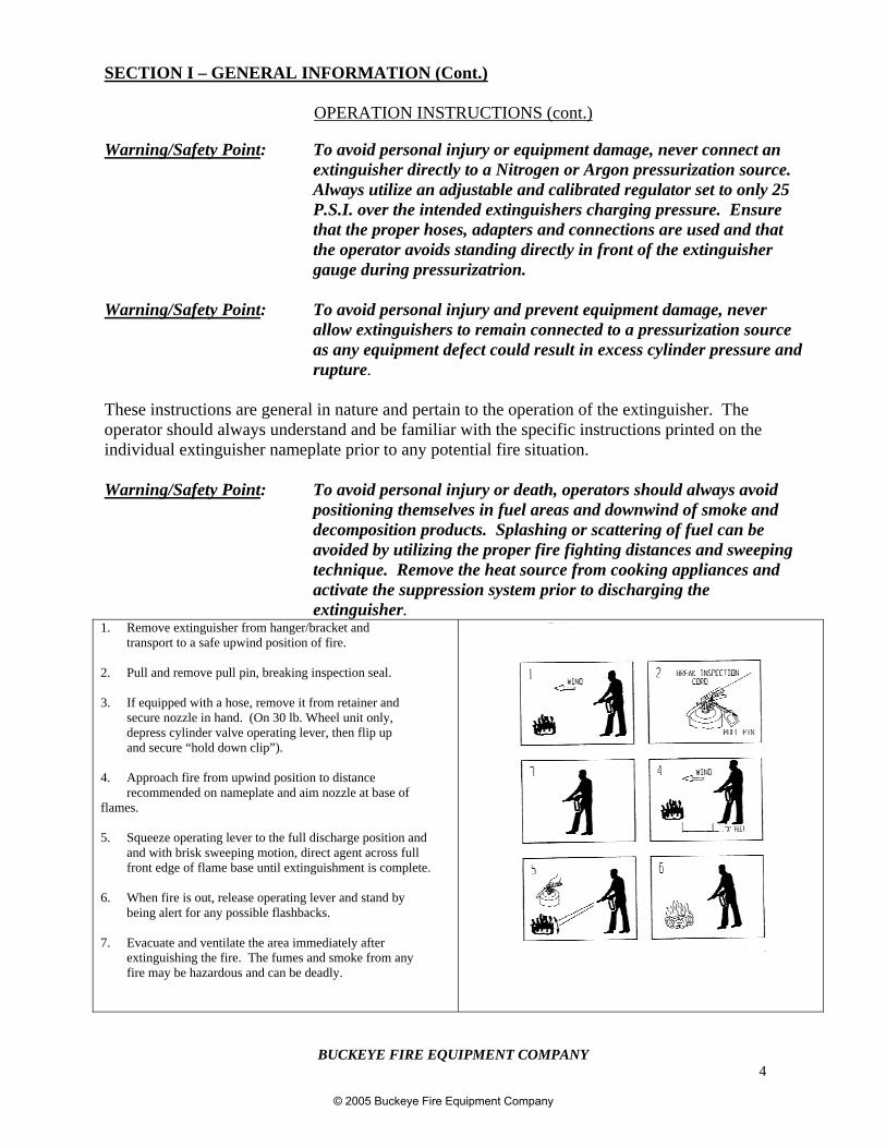
1. Remove extinguisher from hanger/bracket andtransport to a safe upwind position of fire.
2. Pull and remove pull pin, breaking inspection seal.
3. If equipped with a hose, remove it from retainer andsecure nozzle in hand. (On 30 lb. Wheel unit only,depress cylinder valve operating lever, then flip upand secure “hold down clip”).
4. Approach fire from upwind position to distancerecommended on nameplate and aim nozzle at base of
flames.
5. Squeeze operating lever to the full discharge position andand with brisk sweeping motion, direct agent across fullfront edge of flame base until extinguishment is complete.
6. When fire is out, release operating lever and stand bybeing alert for any possible flashbacks.
7. Evacuate and ventilate the area immediately afterextinguishing the fire. The fumes and smoke from anyfire may be hazardous and can be deadly.
© 2005 Buckeye Fire Equipment Company
BUCKEYE FIRE EQUIPMENT COMPANY5
SECTION I – GENERAL INFORMATION (Cont.)
NOTE: When using Wet Chemical Extinguishers discharge entire contents of extinguisher on thefryer surface as this aids in cooling and retards flashbacks.
OPERATING INSTRUCTIONS (Cont.)After a fire, ensure that the proper personnel are notified to initiate corrective action and performimmediate clean-up/disposal of materials once fire area is deemed safe. Should you have anyquestions or desire actual fire training using extinguishers, contact your local distributor or BuckeyeFire Equipment for assistance.
NOTE: Always ensure that the fire extinguisher is properly recharged immediately after anyuse!
BASIC OPERATING INSTRUCTIONS
To operate hand portable extinguishers:
1. Hold upright.
2. Pull pull pin.
3. Start back 10 feet, aim hose or nozzle at base of flame.
4. Squeeze the lever, sweep side to side.
It is very important to note that one should never turn their back on a fire.
© 2005 Buckeye Fire Equipment Company
BUCKEYE FIRE EQUIPMENT COMPANY6
SECTION I – GENERAL INSTRUCTIONS (Cont.)
INSPECTION PROCEDURESInspections should be performed in accordance with NFPA-10 and local governing authoritieshaving jurisdiction.
DEFINITION: Inspection is the “Quick Check” (per NFPA-10 4-3.2) of an extinguisher toensure it is available and ready to use in the event of a fire. It is intended togive reasonable assurance that the extinguisher is charged and operable.
FREQUENCY: Extinguishers shall be inspected when initially placed into service andthereafter at approximately 30 day intervals. When circumstances require,more frequent intervals may be necessary.
NOTE: If inspection of an extinguisher reveals a discrepancy, the extinguisher should besubjected to the applicable maintenance procedure.
GENERAL INSPECTION PROCEDURES:
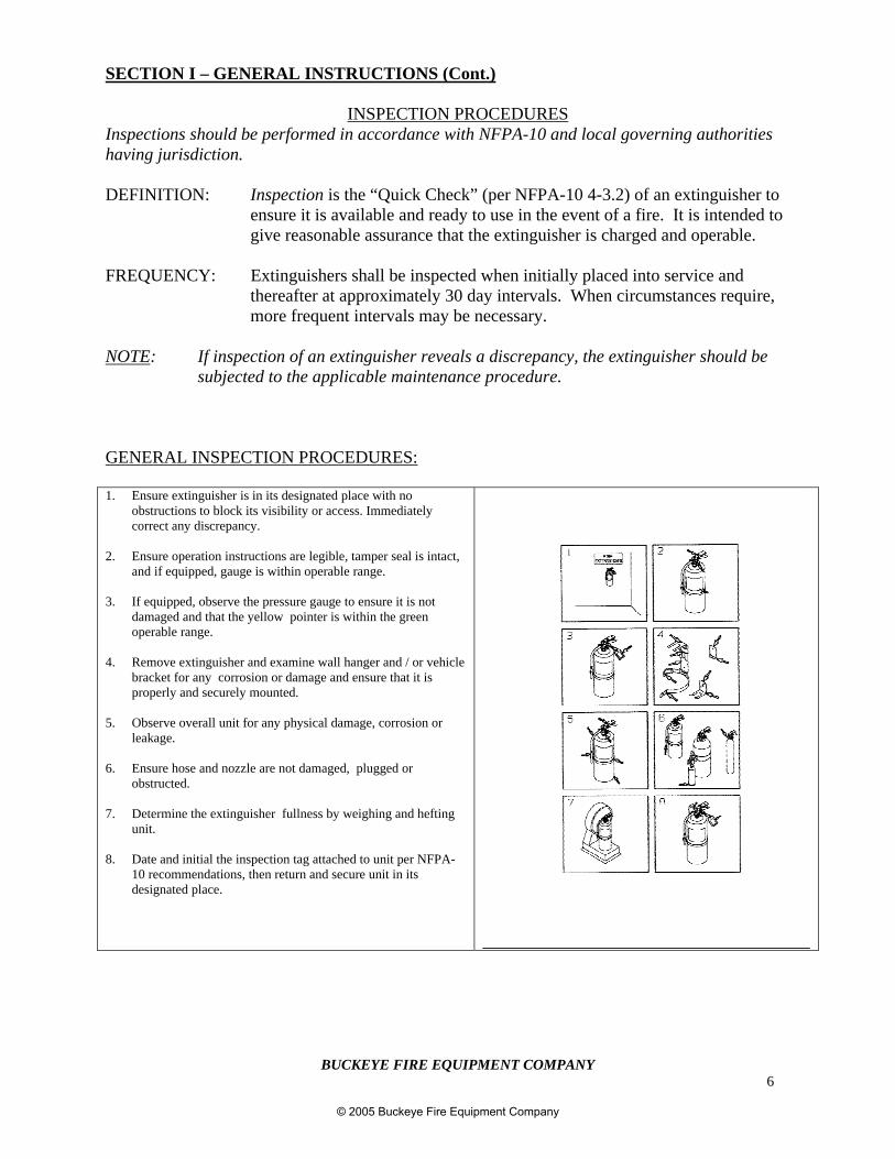
1. Ensure extinguisher is in its designated place with noobstructions to block its visibility or access. Immediatelycorrect any discrepancy.
2. Ensure operation instructions are legible, tamper seal is intact,and if equipped, gauge is within operable range.
3. If equipped, observe the pressure gauge to ensure it is notdamaged and that the yellow pointer is within the greenoperable range.
4. Remove extinguisher and examine wall hanger and / or vehiclebracket for any corrosion or damage and ensure that it isproperly and securely mounted.
5. Observe overall unit for any physical damage, corrosion orleakage.
6. Ensure hose and nozzle are not damaged, plugged orobstructed.
7. Determine the extinguisher fullness by weighing and heftingunit.
8. Date and initial the inspection tag attached to unit per NFPA-10 recommendations, then return and secure unit in itsdesignated place.
© 2005 Buckeye Fire Equipment Company
BUCKEYE FIRE EQUIPMENT COMPANY7
SECTION II – HYDROSTATIC REQUIREMENTS
HYDROSTATIC TESTING REQUIREMENTSPortable fire extinguisher cylinders and certain hose assemblies are subject to various periodicintegrity and hydrostatic (proof pressure) testing requirements. Buckeye Fire Equipmentextinguishers indicating evidence of corrosion or mechanical damage compromise the integrity ofthe pressure vessel and should immediately be removed from service. They shall be subjected to theappropriate test procedures or properly disposed of and replaced. Damaged or questionable hoseassemblies should be replaced.
Buckeye Fire Equipment requires the removal of the operating valve from the cylinder for cylindertesting and the removal of all attachments from hose assemblies that require testing. Only qualifiedindividuals recognized and authorized by D.O.T. may retest Buckeye Fire Equipment CarbonDioxide compressed gas cylinders in accordance with D.O.T. and C.G.A. Requirements/procedures.NFPA-10 provides guidance for testing of non-compressed gas hand portable extinguisher cylindersand hose assemblies.
Warning/Safety Point: To avoid injury or death, always use a safety cage and never usecompressed air or Nitrogen for pressure testing. The use ofcompressible mediums could cause a violent rupture should the vesselfail.
Warning/Safety Point: To avoid injury or death, always ensure all pressure is completelyrelieved prior to attempting to remove or disassemble the operatingvalve or hose assembly.
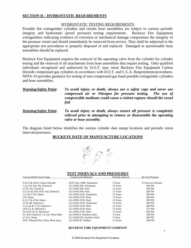
The diagram listed below identifies the various cylinder date stamp locations and periodic retestintervals/pressures.
BUCKEYE DATE OF MANUFACTURE LOCATIONS
TEST INERVALS AND PRESSURESVarious Model Sizes/Types Construction/Material Periodic Interval Re-Test Pressure
5,10,15 & 20 lb. Carbon Dioxide DOT-3AL-1800: Aluminum 5 Years 5/3 Service Pressure1,2,2.5 & 4 lb. Dry Chemical UL/ANSI-299: Aluminum 12 Years 300 PSI2.5 lb. Dry Chemical UL/ANSI-299: Steel 12 Years 300 PSI5,5.5,8,10,20 & 30 lb. Dry Chemical UL/ANSI-299: Steel 12 Years 585 PSI1,2.2 & 2.5 lb. Halon UL/ANSI-2129: Aluminum 12 Years 300 PSI5 lb. Halon UL/ANSI-2129: Steel 12 Years 300 PSI9,13,17 & 20 lb. Halon UL/ANSI-2129: Steel 12 Years 585 PSI2.5 & 3lb. Halotron I UL/ANSI-2129: Aluminum 12 Years 300 PSI2.5,3,5,6 & 11 lb. Halotron I UL/ANSI-2129: Steel 12 Years 300 PSI14 & 15, lb. Halotron I UL/ANSI-2129: Steel 12 Years 375 PSI18, 20 & 24, lb. Halotron I UL/ANSI-2129: Steel 12 Years 450 PSI6 L Wet Chemical 2.5 Gal. Water Mist UL/ANSI-8: Stainless Steel 5 Years 300 PSI2.5 Gal. Water UL/ANSI-626: Stainless Steel 5 Years 300 PSI30 lb. Wheeled Dry Chem. Hose Assy. UL/ANSI-92: Rubber 12 Years 300 PSI
© 2005 Buckeye Fire Equipment Company
BUCKEYE FIRE EQUIPMENT COMPANY8
SECTION III – DRY CHEMICAL EXTINGUISHERS – 133401
MAINTENANCE PROCEDURES
DEFINITION: Maintenance is the thorough examination of the extinguisher and is intended toprovide maximum assurance that it will operate effectively and safely ifneeded. This examination will determine if hydrostatic testing is necessary andif the repair/replacement of serviceable items or recharge is in order. Ifnecessary, follow the applicable Buckeye service/recharge procedures.
FREQUENCY: Maintenance of extinguishers shall be performed at least annually or wheneveran inspection discrepancy dictates.
NOTES: Per NFPA-10, extinguishers out of service for maintenance shall be replacedby spare extinguishers of the same type and at least equal rating.
Trained personnel using the proper tools, lubricants, and manufacturer’srecommended replacement parts should perform maintenance. Thesepersonnel should be able to properly identify any indications of extinguisherdamage or defect and safely correct such conditions per the applicableservice/recharge instructions.
1. Ensure that the extinguisher is in its designated place with no obstructions to block itsvisibility or access. Immediately correct any discrepancies.
2. Ensure that the operating nameplate instructions are legible and face outward. Examine theinspection/service tag to determine if a 6-year teardown is due. (Per NFPA-10; BuckeyeFire Equipment Dry Chemical Extinguishers are subject to a 6-year service/rechargeprocedures as specified in this manual).
3. Check the date of manufacture listed on the nameplate or stamped into the cylinder todetermine if periodic hydrostatic testing if required. Refer to the hydrostatic testingrequirements listed on page 7.
4. Check the extinguisher gauge and verify it is within the proper operating range, undamaged,and of the proper type.
5. Thoroughly examine the extinguisher cylinder and components for any damage, corrosion,burns, repairs, or other conditions that might impair extinguisher function.
6. Examine the nozzle and/or hose assembly for any obstructions, abrasions, cuts, cracks, orthread damage.
7. Examine the top portion of the valve assembly and verify that the valve stem is not corrodedor damaged.
8. Ensure handle and operating lever are not damaged and that the rivets are secure.
© 2005 Buckeye Fire Equipment Company
BUCKEYE FIRE EQUIPMENT COMPANY9
SECTION III – DRY CHEMICAL EXTINGUISHERS – 133401 (cont.)
9. Examine the hose retainer band (if so equipped) and verify it is secure and properly retainsthe hose.
10. Weigh the extinguisher and verify that the correct total charged weight is as noted on theextinguisher nameplate.
11. Wipe all dirt or foreign deposits from the extinguisher with a damp rag.
12. Properly tag the extinguisher per NFPA-10 recommendations and fill out the necessaryrecords.
13. Thoroughly examine the extinguisher wall hanger or vehicle bracket and verify it is notdamaged or worn and that it is securely mounted.
14. Return and secure the extinguisher to its designated location.
WHEELED 30 LB. UNITS – ADDITIONAL MAINTENANCE PROCEDURES
1. While directing the hose nozzle in a safe direction, squeeze the nozzle lever to ensure thatthere is no pressure in the hose assembly. Remove the hose assembly from the extinguishervalve body.
2. Extend the hose assembly and thoroughly examine the hose and couplings for anyobstructions, cuts, cracks, abrasions, or thread damage.
3. Open the hose valve while blowing dry air through the hose assembly to verify its operationand that the hose is clear of obstructions.
4. Remove the extinguisher from the cart by disconnecting the mounting bolts and examine thecart for any damage, broken welds, or corrosion. Verify that the wheels rotate freely and aresecured to the axle.
© 2005 Buckeye Fire Equipment Company
BUCKEYE FIRE EQUIPMENT COMPANY10
SECTION III – DRY CHEMICAL EXTINGUISHERS – 133401 (Cont.)
SERVICE/RECHARGE PROCEDURES
SERVICE PARTS - Replacement parts used in servicing Buckeye Fire Equipmentextinguishers must be authentic Buckeye supplied parts. Refer to thelatest Buckeye Fire Equipment Parts List and the model number locatedon the extinguisher nameplate to ensure correct part number references.
RECHARGE AGENT - Recharge the extinguishers with the agent specified on the extinguishernameplate. Buckeye Fire Equipment extinguishers were tested andlisted with this specified agent. Use of any other agent is unacceptable.
PRESSURIZING GAS - Only standard industrial grade Nitrogen with a dew point of -60°F (-51.1°C) or lower shall be used to pressurize Buckeye Fire EquipmentStored Pressure Dry Chemical Extinguishers. Dry air is notrecommended as it may cause caking of chemical agents.
6-YEAR TEARDOWN - Per NFPA-10, Buckeye Fire Equipment Stored Pressure Dry ChemicalExtinguishers shall be emptied and subjected to these service/rechargeprocedures every 6 (six) years.
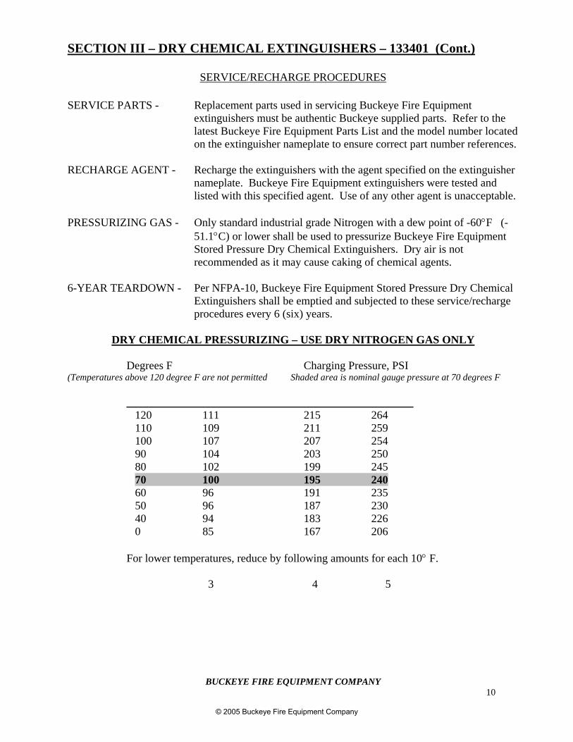
DRY CHEMICAL PRESSURIZING – USE DRY NITROGEN GAS ONLY
Degrees F Charging Pressure, PSI(Temperatures above 120 degree F are not permitted Shaded area is nominal gauge pressure at 70 degrees F
___________________________________________________120 111 215 264110 109 211 259100 107 207 25490 104 203 25080 102 199 24570 100 195 24060 96 191 23550 96 187 23040 94 183 2260 85 167 206
For lower temperatures, reduce by following amounts for each 10° F.
3 4 5
© 2005 Buckeye Fire Equipment Company
BUCKEYE FIRE EQUIPMENT COMPANY11
SECTION III – DRY CHEMICAL EXTINGUISHERS – 133401 (Cont.)
SERVICE/RECHARGE PROCEDURES
1. Remove the pull pin, invert the unit, and depress the operating lever to ensure all pressure isrelieved.
2. Remove the hose/nozzle assembly from the valve with counterclockwise rotations. Verifythat the nozzle orifice (see parts manual for orifice size) is correct for the specific model andthoroughly examine it for any internal blockage, damage, or wear.
NOTE: If at any time worn or damaged thread surfaces are observed, Buckeyerecommends that the part be replaced.
3. Ensure that the nameplate is legible and faces outward.
4. Thoroughly examine the extinguisher cylinder and components for any damage, corrosion,burns, repairs, or other physical conditions that might impair extinguisher function.
5. Check the date of manufacture listed on nameplate or stamped into cylinder to determine ifperiodic hydrostatic testing is necessary. Refer to the hydrostatic testing requirements onPage 7.
6. Remove the valve assembly from the cylinder by rotating counterclockwise.
NOTES: Valve body removal and installation only requires the use of firm handpressure. Avoid the use of mallets as they may damage thread surfaces,handles, gauge, etc.
Ensure that the original valve body and cylinder are kept together duringservice and recharge. These threads are not indexed and impropernameplate orientation may result with intermixing of components.
7. Remove the siphon tube and retainer nut from the valve body by rotating counterclockwise.Examine and replace if any damage or thread wear is evident.
8. Remove the Neck o-ring from the valve and examine it closely. Replace it if any cuts,cracking, or deformation is observed. Lightly lubricate the Neck o-ring.
NOTE: Buckeye advises against the use of any Petroleum Solvents for cleaning andrecommends use of Parker “0” lube for lubrication of o-rings and specifiedthread surfaces.
© 2005 Buckeye Fire Equipment Company
BUCKEYE FIRE EQUIPMENT COMPANY12
SECTION III – DRY CHEMICAL EXTINGUISHERS – 133401 (Cont.)
SERVICE/RECHARGE PROCEDURES (Cont.)
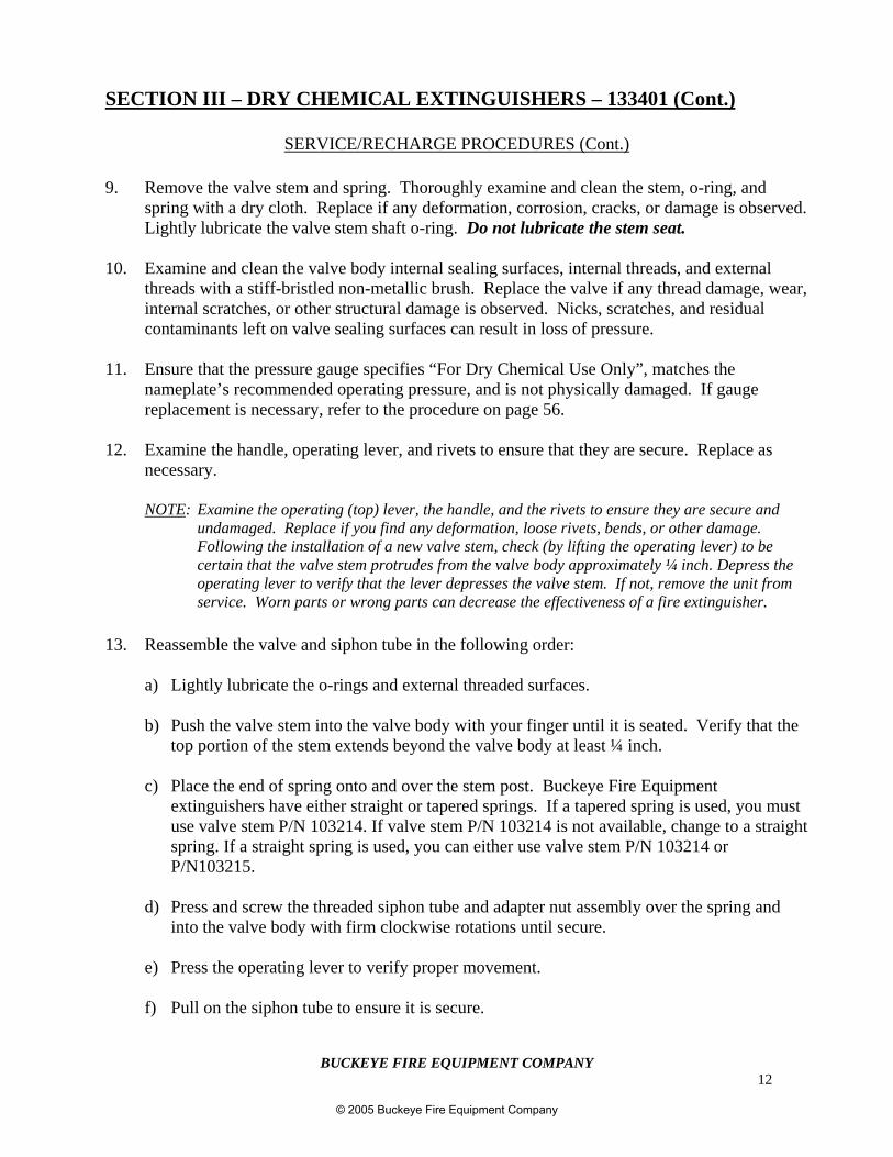
9. Remove the valve stem and spring. Thoroughly examine and clean the stem, o-ring, andspring with a dry cloth. Replace if any deformation, corrosion, cracks, or damage is observed.Lightly lubricate the valve stem shaft o-ring. Do not lubricate the stem seat.
10. Examine and clean the valve body internal sealing surfaces, internal threads, and externalthreads with a stiff-bristled non-metallic brush. Replace the valve if any thread damage, wear,internal scratches, or other structural damage is observed. Nicks, scratches, and residualcontaminants left on valve sealing surfaces can result in loss of pressure.
11. Ensure that the pressure gauge specifies “For Dry Chemical Use Only”, matches thenameplate’s recommended operating pressure, and is not physically damaged. If gaugereplacement is necessary, refer to the procedure on page 56.
12. Examine the handle, operating lever, and rivets to ensure that they are secure. Replace asnecessary.
NOTE: Examine the operating (top) lever, the handle, and the rivets to ensure they are secure andundamaged. Replace if you find any deformation, loose rivets, bends, or other damage.Following the installation of a new valve stem, check (by lifting the operating lever) to becertain that the valve stem protrudes from the valve body approximately ¼ inch. Depress theoperating lever to verify that the lever depresses the valve stem. If not, remove the unit fromservice. Worn parts or wrong parts can decrease the effectiveness of a fire extinguisher.
13. Reassemble the valve and siphon tube in the following order:
a) Lightly lubricate the o-rings and external threaded surfaces.
b) Push the valve stem into the valve body with your finger until it is seated. Verify that thetop portion of the stem extends beyond the valve body at least ¼ inch.
c) Place the end of spring onto and over the stem post. Buckeye Fire Equipmentextinguishers have either straight or tapered springs. If a tapered spring is used, you mustuse valve stem P/N 103214. If valve stem P/N 103214 is not available, change to a straightspring. If a straight spring is used, you can either use valve stem P/N 103214 orP/N103215.
d) Press and screw the threaded siphon tube and adapter nut assembly over the spring andinto the valve body with firm clockwise rotations until secure.
e) Press the operating lever to verify proper movement.
f) Pull on the siphon tube to ensure it is secure.
© 2005 Buckeye Fire Equipment Company
BUCKEYE FIRE EQUIPMENT COMPANY13
g) Place a light dab of lubrication on top of the valve stem.
SECTION III – DRY CHEMICAL EXTINGUISHERS – 133401 (Cont.)
SERVICE/RECHARGE PROCEDURES (Cont.)
14. Empty all of the extinguishing agent from the extinguisher shell and thoroughly examine theinternal and external cylinder condition.
NOTE: If the agent is to be reused, Buckeye recommends the use of a closed recoverysystem. Prior to agent reuse, it should be examined to ensure it is the propertype and that no contamination or caking is present.
Warning/Safety Point: To avoid personal injury or equipment damage, never mix differenttypes of Dry Chemical agents as they may react to produceundesirable internal pressures or other detrimental conditions.
15. Fill the extinguisher to its rated capacity with the Buckeye Dry Chemical specified on theextinguisher nameplate.
16. While carefully centering the siphon tube down into the agent, screw the valve assembly intothe shell with clockwise rotations.
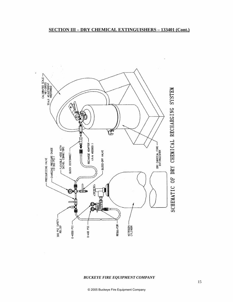
17. Install a Buckeye Recharge Adapter (P/N 600001) into the valve assembly. Refer to thediagram on Page 15 for a typical charging set-up.
18. Connect a regulated nitrogen source, pre-set to 25 P.S.I. over intended charging pressurestated on the extinguisher nameplate, and pressurize the unit by opening the pressure valveand depressing the extinguisher operating lever. Refer to the calibrated charging pressuregauge to determine the charge pressure. Do not rely on the extinguisher gauge for chargingpressure. Close the pressurization valve and release the extinguisher operating lever once theproper charge pressure has been reached. Bleed off the charging line pressure by opening thebleed valve.
19. Insert the extinguisher pull pin into the operating lever, disconnect the pressurization source,and remove the recharge adapter.
20. Install the tamper seal through pull pin. Refer to the diagram on Page 56.
21. Using Leak-Tek or some other suitable medium, perform a leak check on the extinguisher. Ifthe extinguisher leaks, repeat the entire recharge procedure.
© 2005 Buckeye Fire Equipment Company
BUCKEYE FIRE EQUIPMENT COMPANY14
SECTION III – DRY CHEMICAL EXTINGUISHERS – 133401 (Cont.)
SERVICE/RECHARGE PROCEDURES (Cont.)
NOTE: After the leak check is performed, Buckeye recommends that the gaugereading be observed 24 – 48 hours later to verify there is no loss ofpressure.
22. If no leakage is evident, dry the extinguisher and attach the hose and/or nozzle. Secure thehose into the hose band assembly if applicable.
23. Weigh the extinguisher and verify it meets the charged weight specified on the extinguishernameplate.
24. Clean all dirt and foreign deposits from the extinguisher with a damp cloth.
25. Properly record and tag the extinguisher in accordance with NFPA-10 requirements.
26. Return and secure the extinguisher to its designated location.
WHEELED ENGINES – ADDITIONAL SERVICING PROCEDURES
1. Remove the pull pin and invert the wheeled extinguisher by rotating the unit backwardabout its wheel axis and resting it upon its handle. Then, while directing the hose nozzle ina safe and proper direction, squeeze the nozzle lever and valve operating leversimultaneously to relieve all extinguisher pressure.
2. Remove the hose/nozzle assembly from the valve by rotating counterclockwise. Verify thatthe nozzle is correct for the specific unit. Thoroughly examine the nozzle for anyobstructions, cuts, cracks, abrasions, thread damage, or coupling damage.
3. Reconnect the hose assembly and ensure it is coiled correctly per NFPA-10recommendations. Return the nozzle to the cart support post.
4. Examine the handle, operating lever, operation hold down clip, and rivets to ensure that theyare secure. Replace if necessary.
5. Reinstall the pull pin. Install the tamper seal through pull pin. Refer to the diagram on Page56.
© 2005 Buckeye Fire Equipment Company
BUCKEYE FIRE EQUIPMENT COMPANY15
SECTION III – DRY CHEMICAL EXTINGUISHERS – 133401 (Cont.)
© 2005 Buckeye Fire Equipment Company
BUCKEYE FIRE EQUIPMENT COMPANY16
SECTION IV – HALON 1211 FIRE EXTINGUISHERS – 133501
MAINTENANCE PROCEDURES
DEFINITION: Maintenance is the thorough examination of an extinguisher and is intendedto provide maximum assurance that it will operate effectively and safely ifneeded. This examination will determine if hydrostatic testing is necessaryand if the repair/replacement of serviceable items or recharge is in order. Ifnecessary, follow the applicable Buckeye service/recharge procedures.
FREQUENCY: Maintenance of extinguishers shall be performed at least annually or wheneveran inspection discrepancy dictates.
NOTES: Per NFPA-10, extinguishers put out of service for maintenance shall bereplaced by spare extinguishers of the same agent type and, at minimum, equalrating.
Only trained personnel using the proper tools, lubricants, and manufacturerrecommended replacement parts should perform maintenance. These trainedpersonnel should be able to properly identify any indications of extinguisherdamage or defect and safely correct such conditions per the applicableservice/recharge instructions.
Servicing Alert: Effective immediately, all BUCKEYE Halon 1211 fire extinguishers must besubjected to a complete maintenance procedure (teardown) on an annual basisas outlined in this service manual.
It is recommended that all o-rings, valve stem assemblies, and gauges bereplaced with Buckeye genuine replacement parts.
Follow the instructions for proper evacuation and recharge of Halon 1211extinguishers to ensure that water is not introduced into the cylinder.
Noncompliance with this alert relieves Buckeye Fire Equipment of allwarranties and liabilities of this product.
1. Verify that the extinguisher is in its designated place and that there are no obstructions toblock its visibility or access. Immediately correct any discrepancies.
2. Ensure that the operating instructions are legible and facing outward. Examine theinspection/service tag to determine if an annual teardown is due. (Per NFPA-10; Buckeye
© 2005 Buckeye Fire Equipment Company
BUCKEYE FIRE EQUIPMENT COMPANY17
Halon extinguishers are subject to the 6-year service/recharge procedures specified in thismanual. As noted, Buckeye recommends annual teardown.
SERVICE IV – HALON 1211 FIRE EXTINGUISHERS – 133501 (Cont.)
MAINTENANCE PROCEDURES (Cont.)
3. Check that the date of manufacture is listed on the nameplate or stamped into the cylinder.To determine if periodic hydrostatic testing is necessary, refer to the hydrostatic testingrequirements on page 7.
4. Check the extinguisher gauge and verify it is within the proper operating range, notdamaged, and is of the proper type. Replace annually.
5. Thoroughly examine the extinguisher cylinder and components for any damage, corrosion,burns, repairs, or other physical conditions that might impair extinguisher function. Replacethe valve stem shaft and neck o-rings.
6. Examine the nozzle and/or hose assembly for any obstructions, abrasions, cuts, cracks, orthread damage.
7. Examine the top portion of the valve assembly and verify that the valve stem is not corrodedor damaged.
8. Verify that the handle and operating lever are not damaged and that the rivets are secure.
9. Examine the hose retainer band (if so equipped) and verify that it is secure and that itproperly retains the hose.
10. Weigh the extinguisher and verify that it meets the total charged weight specified on theextinguisher nameplate.
11. Wipe all dirt or foreign deposits from the extinguisher with a damp cloth.
12. Properly tag the extinguisher per NFPA-10 recommendations and fill out necessary records.
13. Thoroughly examine the extinguisher wall hanger or vehicle bracket and verify that it is notdamaged or worn and that it is securely mounted.
14. Return and secure the extinguisher to its designated location.
© 2005 Buckeye Fire Equipment Company
BUCKEYE FIRE EQUIPMENT COMPANY18
SECTION IV – HALON 1211 FIRE EXTINGUISHERS – 133501 (Cont.)
SERVICE/RECHARGE AND RECLAIM PROCEDURES
SERVICE PARTS - Replacement parts used in servicing Buckeye Fire Equipmentextinguishers must be authentic Buckeye supplied parts. Refer to thelatest Buckeye Parts List and the model number located on theextinguisher nameplate to ensure correct part number references.
RECHARGE AGENT - Recharge the Buckeye Halon 1211 unit with pure, uncontaminatedBromochlorodifluoromethane, which meets military specificationMIL-B-38741 dated July 30, 1965 and amendment No. 2 dated April9, 1984.
PRESSURIZING GAS - Only standard industrial grade Nitrogen with a dew point of -60°F (-51.1°C) or lower shall be used to pressurize Buckeye Fire Equipmentstored pressure Halon extinguishers. Dry air is not recommended.
1-YEAR TEARDOWN- Buckeye Fire Equipment stored Halon 1211 extinguishers shall beemptied and subjected to these service/recharge and reclaimprocedures every year.
NOTE: The Montreal Protocol had defined Halon 1211 as an ozone depleting gas.In accordance with NFPA-10 requirements, any agent removal or filling ofHalon 1211 extinguishers is to be done using a “listed” closed recoveryHalon system only. There are several systems commercially available thatwill properly handle all models of Buckeye Halon 1211 extinguishers.Because these systems vary somewhat in design, Buckeye recommends thatthe systems specific recovery and filling procedures be followed wheneverthe servicing of Buckeye Halon extinguishers is necessary.
THE FOLLOWING SERVICE/RECHARGE PROCEDURES SHOULD BE FOLLOWEDREGARDLESS OF WHAT TYPE OF SYSTEM IS UTILIZED.
1. Prior to performing any service, ensure that all of the Halon 1211 and pressure is removed.(Use “listed” closed recovery system). Refer to page 22 for typical recharge arrangement.
2. Remove the hose/nozzle assembly from the valve (if not already removed) by rotatingcounterclockwise. Verify that the nozzle is correct for the specific model. Thoroughlyexamine it for any internal blockage, external damage, or wear.
3. Verify that the nameplate is legible and facing outward.
4. Thoroughly examine the extinguisher cylinder and components for any damage, corrosion,burns, repairs, or other physical conditions that might impair extinguisher function.
© 2005 Buckeye Fire Equipment Company
BUCKEYE FIRE EQUIPMENT COMPANY19
SECTION IV – HALON 1211 FIRE EXTINGUISHERS – 133501 (Cont.)
SERVICE/RECHARGE AND RECLAIM PROCEDURES
5. Check the date of manufacture listed on the nameplate or stamped into the cylinder. Todetermine if periodic hydrostatic testing is necessary, refer to the hydrostatic testingrequirements on Page 7.
6. Remove the valve assembly from the cylinder by rotating it counterclockwise.
NOTES: Valve body removal and installation only requires the use of firm handpressure. Avoid the use of mallets as they may damage thread surfaces,handles, gauge, etc.
Ensure that the valve body and shell are kept together during service andrecharge. The threads are not indexed and improper nameplate orientationmay result from intermixing of components.
7. Remove the siphon tube from the valve body by rotating it counterclockwise. Examine andreplace if any damage or thread wear is evident.
8. Remove the neck 0-Ring from the valve and discard. Replace with a new neck o-ring andlightly lubricate.
NOTE: Buckeye advises against the use of any Petroleum Solvents for cleaning andrecommends the use of Visilox 711 lube for lubrication of o-rings andspecified thread surfaces. Do not lubricate stem seat.
9. Remove the valve stem and spring. Thoroughly examine and clean the spring with a drycloth. Replace the spring if any deformation, corrosion, cracks or damage is evident.Replace the valve stem with a new one and lubricate the valve stem o-ring.
10. Examine and clean the valve body internal sealing surfaces, internal threads, and externalthreads with a stiff-bristled non-metallic brush. Replace the valve if any thread damage,wear, internal scratches, or other structural damage is evident.
11. Verify that the new pressure gauge specifies “For Halon 1211 Use Only” and matches thenameplate’s recommended operating pressure. Refer to the procedures on Page 56 forproper gauge replacement procedures.
© 2005 Buckeye Fire Equipment Company
BUCKEYE FIRE EQUIPMENT COMPANY20
SECTION IV – HALON 1211 FIRE EXTINGUISHERS – 133501 (Cont.)
SERVICE/RECHARGE AND RECLAIM PROCEDURES
12. Examine the handle, operating lever, and rivets to ensure that they are secure. Replace ifnecessary.
NOTE: Examine the operating (top) lever, handle, and rivets to ensure they aresecure and undamaged. Replace components if you find any deformation,loose rivets, bends, or other damage. Following the installation of a newvalve stem, check (by lifting the operating lever) to be certain that the valvestem protrudes from the valve body approximately ¼ inch. The operatinglever should be depressed to assure that the lever engages and depresses thevalve stem top. If not, remove the unit from service. Worn parts or wrongparts can decrease the effectiveness of a fire extinguisher.
13. Reassemble the valve and siphon tube in the following order:
a) Using Visilox o-ring lube, sparsely lubricate the o-rings and metal external threadedsurfaces.
b) Using your finger, push the valve stem into the valve body until seated.
c) Place the end of the spring onto and over the stem post. Buckeye Fire Equipmentextinguishers have either straight or tapered springs. If a tapered spring is used, you mustuse valve stem P/N 103214. If valve stem P/N 103214 is not available, change to a straightstem. If a straight spring is used, you can use either valve stem P/N 103214 or P/N103215.
d) Press and screw the threaded siphon tube and adapter nut assembly over the spring andinto the valve body with firm clockwise rotations until secure.
e) Press the operating lever to assure proper movement.
f) Pull on the siphon tube to ensure it is secure.
g) Place a small dab of lubrication on top of the valve stem.
14. Install the valve assembly into the cylinder with clockwise rotations.
15. Fill the extinguisher to its rated capacity as specified on the extinguisher’s nameplate. Useonly pure, clean, uncontaminated Halon 1211 when charging Buckeye Halon 1211extinguishers.
16. Pressurize the extinguisher with dry nitrogen to the specified charging pressure indicated onthe nameplate by opening the pressure valve and depressing the operating lever. Refer to
© 2005 Buckeye Fire Equipment Company
BUCKEYE FIRE EQUIPMENT COMPANY21
the calibrated charging pressure gauge to determine charge pressure. Do not rely on theextinguisher gauge for charging pressure.
SECTION IV – HALON 1211 FIRE EXTINGUISHERS – 133501 (Cont.)
SERVICE/RECHARGE AND RECLAIM PROCEDURES
17. Insert the extinguisher pull pin into the operating lever and then disconnect thepressurization source and remove the recharge adapter. Install an inspection seal throughpull pin. Refer to the diagram on page 56.
18. Check for leaks around the nozzle, gauge, valve body, and cylinder neck area with a Halonleak detector (Do not use water). If leaks are detected, depressurize the unit and repeat theabove steps, concentrating on the area where the leak was detected.
NOTE: After the leak check is performed, it is recommended that the gaugereading be observed 24 – 48 hours later to assure against loss ofpressure.
19. If no leakage is evident, attach the hose and/or nozzle and secure the hose into hose bandassembly if so equipped.
20. Weigh the extinguisher and verify that the correct total charged weight is as specified on theextinguisher nameplate.
21. Clean all dirt and foreign deposits from extinguisher with a damp cloth.
22. Properly tag the extinguisher per NFPA-10 recommendations and fill out necessary records.
© 2005 Buckeye Fire Equipment Company

BUCKEYE FIRE EQUIPMENT COMPANY22
SECTION IV – HALON 1211 FIRE EXTINGUISHERS – 133501 (Cont.)
© 2005 Buckeye Fire Equipment Company
BUCKEYE FIRE EQUIPMENT COMPANY23
SECTION V - HALOTRON I FIRE EXTINGUISHERS - 133901
PROPERTIES OF HALOTRON I
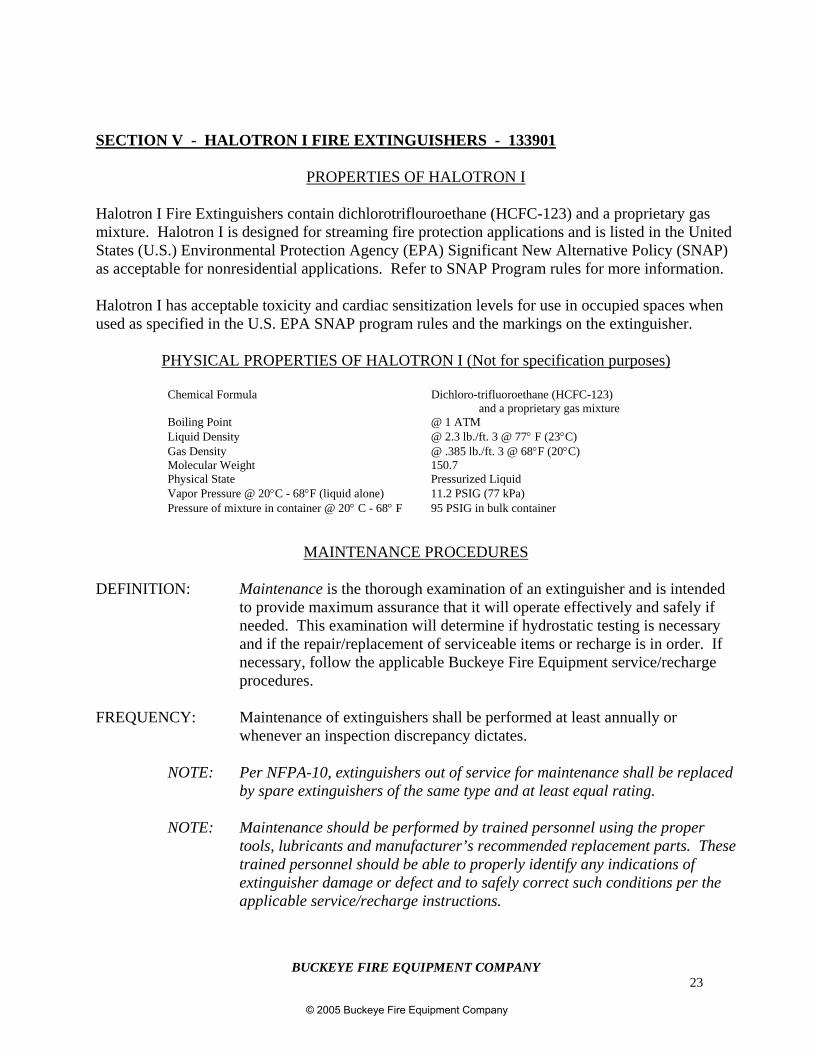
Halotron I Fire Extinguishers contain dichlorotriflouroethane (HCFC-123) and a proprietary gasmixture. Halotron I is designed for streaming fire protection applications and is listed in the UnitedStates (U.S.) Environmental Protection Agency (EPA) Significant New Alternative Policy (SNAP)as acceptable for nonresidential applications. Refer to SNAP Program rules for more information.
Halotron I has acceptable toxicity and cardiac sensitization levels for use in occupied spaces whenused as specified in the U.S. EPA SNAP program rules and the markings on the extinguisher.
PHYSICAL PROPERTIES OF HALOTRON I (Not for specification purposes)
Chemical Formula Dichloro-trifluoroethane (HCFC-123)and a proprietary gas mixture
Boiling Point @ 1 ATMLiquid Density @ 2.3 lb./ft. 3 @ 77° F (23°C)Gas Density @ .385 lb./ft. 3 @ 68°F (20°C)Molecular Weight 150.7Physical State Pressurized LiquidVapor Pressure @ 20°C - 68°F (liquid alone) 11.2 PSIG (77 kPa)Pressure of mixture in container @ 20° C - 68° F 95 PSIG in bulk container
MAINTENANCE PROCEDURES
DEFINITION: Maintenance is the thorough examination of an extinguisher and is intendedto provide maximum assurance that it will operate effectively and safely ifneeded. This examination will determine if hydrostatic testing is necessaryand if the repair/replacement of serviceable items or recharge is in order. Ifnecessary, follow the applicable Buckeye Fire Equipment service/rechargeprocedures.
FREQUENCY: Maintenance of extinguishers shall be performed at least annually orwhenever an inspection discrepancy dictates.
NOTE: Per NFPA-10, extinguishers out of service for maintenance shall be replacedby spare extinguishers of the same type and at least equal rating.
NOTE: Maintenance should be performed by trained personnel using the propertools, lubricants and manufacturer’s recommended replacement parts. Thesetrained personnel should be able to properly identify any indications ofextinguisher damage or defect and to safely correct such conditions per theapplicable service/recharge instructions.
© 2005 Buckeye Fire Equipment Company
BUCKEYE FIRE EQUIPMENT COMPANY24
SECTION V – HALOTRON I FIRE EXTINGUISHERS – 133901 (Cont.)
MAINTENANCE PROCEDURES (cont.)
1. Verify the extinguisher is in its designated place with no obstructions to block its visibility oraccess. Immediately correct any discrepancies.
2. Verify the operating instructions are legible and face outward. Examine the inspection/servicetag to determine if a 6-year teardown is due. (Halotron I Extinguishers are subject to the 6-yearservice/recharge procedures specified in this manual).
3. Check that the date of manufacture is listed on the nameplate or stamped into the cylinder todetermine if periodic hydrostatic testing is necessary. Refer to the hydrostatic testingrequirements listed on page 7.
4. Check the extinguisher gauge and verify it is within the proper operating range, undamaged, andis of the proper type.
5. Thoroughly examine the extinguisher cylinder and components for any damage, corrosion,burns, repairs, or other conditions that might impair extinguisher function.
6. Examine the nozzle and/or hose assembly for any obstructions, abrasions, cuts, cracks, or threaddamage.
7. Examine the top portion of the valve assembly and verify that the valve stem is not corroded ordamaged.
8. Verify that the handle and operating lever are not damaged and that the rivets are secure.
9. Examine the hose retainer band (if so equipped) and verify it is secure and properly retains thehose.
10. Weigh the extinguisher and verify it is within the correct total charged weight specified on theextinguisher nameplate.
11. Wipe all dirt or foreign deposits from the extinguisher with a damp cloth.
12. Properly tag the extinguisher per NFPA-10 recommendations and fill out necessary records.
13. Thoroughly examine the extinguisher wall hanger or vehicle bracket and verify it is notdamaged or worn and that it is securely mounted.
14. Return and secure the extinguisher to its designated location.
© 2005 Buckeye Fire Equipment Company
BUCKEYE FIRE EQUIPMENT COMPANY25
SECTION V – HALOTRON I FIRE EXTINGUISHERS – 133901 (Cont.)
SERVICE/RECHARGE PROCEDURES
SERVICE PARTS: Replacement parts used in servicing Buckeye Fire Equipmentextinguishers must be authentic Buckeye supplied parts. Refer to thelatest Buckeye Fire Equipment Parts List and the model numberlocated on the extinguisher nameplate to ensure correct part numberreferences.
RECHARGE AGENT: Recharge Halotron I units with pure pre-saturated Halotron I suppliedby Buckeye Fire Equipment. Follow the instructions in the HalotronRecharging Kit or as follows to properly fill and pressurize the unit.
PRESSURIZING GAS: Only ultra high purity Argon shall be used to pressurize StoredPressure Halotron I extinguishers. Dry air and nitrogen are not to beused.
VACUUM PROCEDURE: It is necessary to draw a vacuum of 27 inches mercury prior torefilling a unit to make certain all moisture is removed from thecylinder. See instructions on vacuum system for proper procedures.
6-TEAR TEARDOWN Per NFPA-10, stored pressurized fire extinguishers shall be emptiedand subjected to these service/recharge procedures every six (6)years.
WARNING/SAFETY POINT: As specified in ANSI/UL 2129 and outlined on each unitlabel, this concentrated agent can produce toxic byproducts.Avoid inhalation of these materials by evacuating theconfined space. Do not use in confined spaces less thanspecified in the warning statement on the extinguisher label.
THE FOLLOWING SERVICE/RECHARGE PROCEDURES SHOULD BE FOLLOWEDREGARDLESS OF WHAT TYPE OF SYSTEM IS UTILIZED
1. Prior to performing any service, ensure all Halotron I and pressure are removed from thecylinder.
2. Remove the hose/nozzle assembly from the valve (if not already removed) with counter-clockwise rotations. Verify that the nozzle is correct for the specific model and thoroughlyexamine it for any internal blockage or external damage and wear.
3. Verify the nameplate is legible and faces outward.
© 2005 Buckeye Fire Equipment Company
BUCKEYE FIRE EQUIPMENT COMPANY26
4. Thoroughly examine the extinguisher cylinder and components for any damage, corrosion,burns, repairs, or other conditions that might impair extinguisher function.
SECTION V – HALOTRON I FIRE EXTINGUISHERS – 133901 (Cont.)
SERVICE/RECHARGE PROCEDURES (cont.)
5. Check the date of manufacture listed on the nameplate or stamped into the cylinder to determineif periodic hydrostatic testing is necessary. Refer to the hydrostatic testing requirements onpage 7.
6. Remove the valve assembly from the cylinder with counter-clockwise rotations.
NOTE: Normal valve body removal and installation only requires the use of firmhand pressure. Avoid the use of mallets as they may damage thread surfaces,handles, gauges, etc.
NOTE: Ensure that the original valve body and cylinder are kept together duringservice and recharge. The threads are not indexed and improper nameplateorientation may result with intermixing of components.
7. Remove the siphon tube from the valve body with counter-clockwise rotations. Examine andreplace if any damage or thread wear is evident.
8. Remove the neck o-ring from the valve and discard. Replace with a new lightly lubricated o-ring.
NOTE: Buckeye Fire Equipment advises against the use of any petroleum solventsfor cleaning. The use of “Visilox 711” lube for lubrication of o-rings andspecified thread surfaces is recommended. Do not lubricate the stem seat.
9. Remove the valve stem and spring. Thoroughly examine and clean the spring with a dry cloth.Replace if any deformation, corrosion, cracks, or damage is evident. Replace the valve stemassembly with a new one (as it may be saturated with Halotron I) and lubricate the valve stem
o-ring.
10. Examine and clean the valve body internal seating surfaces, internal threads, and externalthreads with a stiff-bristled (non-metallic) brush. Replace the valve if any thread damage, wear,internal scratches, or other structural damage is evident.
NOTE: Nicks, scratches, or residual contaminants left on valve seating surfaces canresult in a loss of pressure.
11. Verify that the operating gauge specifies “For Halotron I Use Only”, matches the nameplate’srecommended operating pressure, and is undamaged. If gauge replacement is necessary, referto the procedure on page 56.
© 2005 Buckeye Fire Equipment Company
BUCKEYE FIRE EQUIPMENT COMPANY27
SECTION V – HALOTRON I FIRE EXTINGUISHERS – 133901 (Cont.)
SERVICE/RECHARGE PROCEDURES (cont.)
12. Examine the handle, operating lever, and rivets to ensure that they are secure. Replace asnecessary.
NOTE: Examine the operating (top) lever, handle, and rivets to verify they aresecure and undamaged. Replace the unit if you find any deformation, looserivets, bends, or other damage.
Following the installation of a new valve stem, check (by lifting the operatinglever) that the valve stem protrudes from the valve body approximately ¼inch. The operating lever should be depressed to assure that the leverengages and depresses the valve stem top. If not, remove the unit fromservice. Worn parts or wrong parts can decrease the effectiveness of a fireextinguisher.
13. Reassemble the valve and siphon tube in the following order:
a) With Visilox o-ring lube, lightly lubricate the o-rings and external threaded surfaces.b) Using a finger, push the valve stem into the valve body until it seats.c) Place the end of the spring onto and over the stem post.d) Press and screw the threaded metal siphon tube over the spring and into the valve body
with firm clockwise rotations until it is secure.e) Press the operating lever to assure proper movement.f) Pull on the siphon tube to verify it is secure.g) Place a small dab of lubrication on top of the valve stem.
14. Install the valve assembly into the cylinder with clockwise rotations.
CAUTION: The following are general instructions for recharging Halotron Ifire extinguishers. However, Buckeye Fire Equipment highlyrecommends the use of it’s designated “HALOTRON IRECHARGING KIT”, Part No. 64000, for the proper vacating,filling, and pressurizing of Halotron I extinguishers.
15. Pull a vacuum of 27 inches mercury (at sea level, this will vary with altitude) on the cylinderprior to filling. (See your vacuum pump manual for additional operating instructions.)
16. Fill the extinguisher to its rated capacity as specified on the extinguisher’s nameplate. Use onlypure, clean, uncontaminated Halotron I when recharging extinguishers.
© 2005 Buckeye Fire Equipment Company
BUCKEYE FIRE EQUIPMENT COMPANY28
17. Connect the cylinder to be filled to a Halotron I supply tank. The supply tank must bepressurized with Argon to approximately 100 PSI in order to fill a unit. Place the unit on ascale. Press the operating lever until the desired charge weight is obtained.
SECTION V – HALOTRON I FIRE EXTINGUISHERS – 133901 (Cont.)
SERVICE/RECHARGE PROCEDURES (Cont.)
WARNING/SAFETY POINT: To avoid personal injury or equipment damage, neverconnect an extinguisher directly to an Argonpressurization source. Always utilize an adjustableand calibrated Halotron I regulator set at 25 PSIover the intended extinguisher charging pressure.Ensure that the proper hoses, adapters, andconnections are used and that the operator avoidsstanding directly in front of the extinguisher gaugewhen pressurizing the unit.
WARNING/SAFETY POINT: To avoid personal injury and prevent equipmentdamage, never allow extinguishers to remainconnected to a pressurization source as anyequipment defect could result in excess cylinderpressure and rupture.
18. Pressurize the extinguisher with Argon to the specified charging pressure indicated on thenameplate by opening the pressure valve and depressing the extinguisher operating lever. Referto the calibrated charging pressure gauge to determine charge pressure. Do not rely on theextinguisher gauge for charging pressure. Set the regulator not more than 25 PSIG above theunit charge pressure.
19. In order to mix the Halotron pre-saturated agent with the Argon, it will be necessary to rock theextinguisher horizontally a few times and then check to make certain the pressure is within itsoperating range. Top off the pressure until the proper pressure is reached.
20. Insert the extinguisher pull pin into the operating lever. Disconnect the pressurization sourceand remove the recharge adapter. Install an inspection seal through the pull pin. Refer to thediagram on page 56.
21. Using a Halotron leak detector or Leak-Tek, check around the nozzle, gauge, valve body, andcylinder neck area for leaks. (When using Leak-Tek, look for bubbles). Do not use water ifleaks are detected. Depressurize the unit and repeat the above steps, concentrating on the areawhere the leak was detected.
NOTE: After the leak check is performed, it is recommended that the gauge readingbe observed 24 – 48 hours later to assure against loss of pressure.
© 2005 Buckeye Fire Equipment Company
BUCKEYE FIRE EQUIPMENT COMPANY29
22. If no leakage is evident, attach the hose and/or nozzle and secure the hose into the hose bandassembly, if so equipped.
23. Weigh the extinguisher and verify it is within the correct total charged weight as specified onthe extinguisher nameplate.
SECTION V – HALOTRON I FIRE EXTINGUISHERS – 133901 (Cont.)
SERVICE/RECHARGE PROCEDURES (Cont.)
24. Clean all dirt and foreign deposits from extinguisher with a damp cloth.
25. Properly tag the extinguisher in accordance with NFPA-10 requirements and fill out necessaryrecords.
26. Return and secure the extinguisher to its designated location.
ALTERNATE A
THE FOLLOWING PROCEDURE SHOULD BE FOLLOWED WHEN RECLAIMING PARTIALLYUSED HALOTRON I FIRE EXTINGUISHERS.
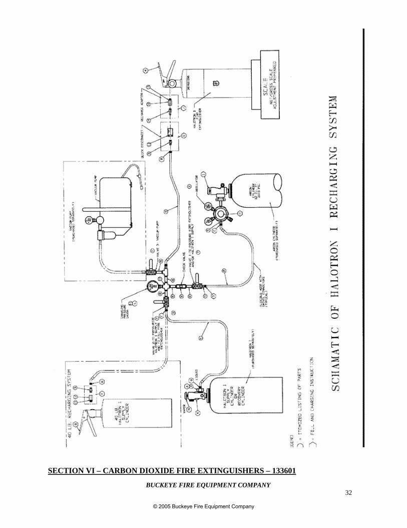
It will be necessary to purchase an empty Halotron Recovery Cylinder to act as a holding tank for reclaimedHalotron I. You may pressurize the holding tank to refill other extinguishers that you are servicing. Seepage 31 for typical Recharge System.
Before proceeding, make sure the Halotron I is not contaminated. If clean, proceed as follows:
1) Unscrew the discharge hose or nozzle from the valve body.2) Screw a fill adapter into the valve body.3) Connect the cylinder to be emptied to the reclaim tank using proper type hose.4) Open the liquid valve and close the vapor valve connections on the reclaim tank.5) Press the operating lever down until the extinguisher to be emptied has discharged completely.6) Close the liquid valve on the reclaim tank.7) Check to make certain the unit is empty. It may be necessary to bring the pressure up to the charge
pressure to discharge the entire contents into the reclaim tank. Also, after discharging a number ofunits into the reclaim tank, it may be necessary to bleed off pressure by momentarily opening thevapor valve.
NOTE: After the unit has been emptied, proceed with servicing as outlined beginning on page 25.
ALTERNATE B
THE FOLLOWING PROCEDURE SHOULD BE FOLLOWED FOR REMOVING HALOTRON I FROMUNITS THAT HAVE LEAKED ALL PRESSURE.
NOTE: It will be necessary to have a Buckeye Halotron I Recharging Kit, Part No. 64000, and itsinstructions before proceeding with this operation.
© 2005 Buckeye Fire Equipment Company
BUCKEYE FIRE EQUIPMENT COMPANY30
If the extinguisher has leaked pressure to a level below 50 PSIG, it should be considered a “leaker” andshould be recovered in a different manner as described in Section IV. This is to ensure quality of thechemical blend, which includes (HCFC-123) and a proprietary gas mixture.
IMPORTANT: Before proceeding, make sure that the remaining material in the extinguisher isnot contaminated. If it is clean, then proceed.
SECTION V – HALOTRON I FIRE EXTINGUISHERS – 133901 (Cont.)
SERVICE/RECHARGE PROCEDURES (Cont.)
The material is to be placed into a Halotron I Recovery Cylinder. The Recovery Cylinder should bepartially emptied by at least the amount to be added.
REPRESSURIZE THE LEAKER FOR RECOVERY OF THE AGENT AS FOLLOWS:
1) Make sure the lines are purged and valves 1, 2, and 3 are in the closed position.
2) Adjust the Argon regulator handle (H) 25 PSIG above the extinguisher operating pressure.
NOTE: Be certain that the pressure in the Recovery Cylinder is less than the operatingpressure of the extinguisher being serviced. This prevents flow into the extinguisher.
3) Unscrew the discharge hose or nozzle from the valve body.
4) Screw the fill adapter (J) into the valve body (M).
5) Connect the quick disconnect (G) to the fill adapter (J).
6) Slowly open the Argon tank valve (I) all the way.
7) Open valve #1 slowly.
8) Open the extinguisher operating lever (M) until pressure stabilizes.
9) Close the extinguisher operating lever (M).
10) Close valve #1.
PROCEED WITH TRANSFERRING HALOTRON I INTO RECOVERY CYLINDER ASFOLLOWS:
11) Vent hose (6).
12) Open the supply cylinder liquid valve (K).
13) Open the extinguisher operating lever (M).
© 2005 Buckeye Fire Equipment Company
BUCKEYE FIRE EQUIPMENT COMPANY31
14) Open valve #2 to allow the flow of the extinguisher contents back into the Recovery Cylinder.
SECTION V – HALOTRON I FIRE EXTINGUISHERS – 133901 (Cont.)
© 2005 Buckeye Fire Equipment Company
BUCKEYE FIRE EQUIPMENT COMPANY32
SECTION VI – CARBON DIOXIDE FIRE EXTINGUISHERS – 133601
© 2005 Buckeye Fire Equipment Company
BUCKEYE FIRE EQUIPMENT COMPANY33
MAINTENANCE PROCEDURES
DEFINITION: Maintenance is the thorough examination of an extinguisher and is intendedto provide maximum assurance that it will operate effectively and safety ifneeded. This examination will determine if hydrostatic testing is necessaryand if the repair/replacement of serviceable items or recharge is in order. Ifnecessary, follow the applicable Buckeye service/recharge procedures.
FREQUENCY: Maintenance of extinguishers shall be performed at least annually orwhenever an inspection discrepancy dictates.
NOTE: Per NFPA-10, extinguishers out of service for maintenance shall be replacedby spare extinguishers of the same type and at least equal rating.
NOTE: Maintenance should be performed by trained personnel using the propertools, lubricants and manufacturer’s recommended replacement parts. Thesetrained personnel should be able to properly identify any indications ofextinguisher damage or defect and to safely correct such conditions per theapplicable service/recharge instructions.
===============================================
1. Verify that the extinguisher is in its designated place with no obstructions to block itsvisibility or access. Immediately correct any discrepancies.
2. Verify the operating instructions are legible and face outward.
3. Check that the date of manufacture is listed on the nameplate or stamped into the cylinder todetermine if periodic hydrostatic testing is necessary. Refer to hydrostatic testingrequirements listed on page 7.
4. Visually examine the safety relief assembly for any damage, corrosion or obstruction.
5. Thoroughly examine the extinguisher cylinder and components for any damage, corrosion,burns, repairs, or other conditions that might impair the extinguisher function.
NOTE: For additional inspection pertaining to aluminum compressed gas cylinders,refer to CGA Pamphlet C-6.1.
6. Remove the hose and horn to examine for any obstructions, abrasions, cuts, cracks or threaddamage. Verify that it is correct for the specified model extinguisher.
7. On 10 lb., 15 lb., and 20 lb. models, inspect the diffuser holes to ensure that they areundamaged and not obstructed.
SECTION VI – CARBON DIOXIDE FIRE EXTINGUISHERS – 133601
© 2005 Buckeye Fire Equipment Company
BUCKEYE FIRE EQUIPMENT COMPANY34
MAINTENANCE PROCEDURES (Cont.)
8. Perform a conductivity test on all 10, 15 and 20 lb. Hose Assemblies per NFPA-10recommendations, then reinstall the hose assembly. (The hose shall be replaced if it does notmeet test requirements). Label the hose assemblies passing conductivity test per NFPA-10recommendations.
9. Examine the top portion of the valve assembly and verify that the valve stem is not corrodedor damaged. Replace it if necessary.
10. Verify that the handle and operating lever are not damaged and that the rivets are secure.
11. Weigh the extinguisher, verifying the total charge weight stamped into the valve body againstthe nameplate recommendations.
12. Clean all dirt or foreign deposits from the extinguisher with a damp cloth.
13. Properly tag the extinguisher per NFPA-10 recommendations and fill out the necessaryrecords.
14. Thoroughly examine the extinguisher wall hanger or vehicle bracket and verify it is notdamaged or worn and that it is securely mounted.
15. Return and secure the extinguisher to its designated location.
SECTION VI – CARBON DIOXIDE FIRE EXTINGUISHERS – 133601
© 2005 Buckeye Fire Equipment Company
BUCKEYE FIRE EQUIPMENT COMPANY35
SERVICE/RECHARGE PROCEDURES
SERVICE PARTS: Replacement parts used in servicing Buckeye Fire Equipmentextinguishers must be authentic Buckeye supplied parts. Refer to thelatest Buckeye Fire Equipment Parts List and the model numberlocated on the extinguisher nameplate to ensure correct part numberreferences.
RECHARGE AGENT: Buckeye Fire Equipment extinguishers shall only be recharged withuncontaminated carbon dioxide having a vapor phase equal to orgreater than 99.5%. The water content of the liquid phase shall notbe more than 0.001% by weight (-30° F [-34.4° C] dew point). Oilcontent of the carbon dioxide shall not exceed 10 ppm by weight.
WARNING/SAFETY POINT: To avoid personal injury, always use gloves and eye protectionwhen servicing carbon dioxide extinguishers. The agentdischarge is very cold and can cause frostbite or freeze burns.
WARNING/SAFETY POINT: To avoid personal injury or death, always service anddischarge carbon dioxide extinguishers in well ventilatedareas. Sufficient concentrations of carbon dioxide will depletethe oxygen supply which can result in a loss of consciousnessand possible death.
WARNING/SAFETY POINT: To avoid personal injury or equipment damage, always ensurethe correct Buckeye safety relief components specified in theParts List are used. Improper parts could result in seriouscylinder rupture.
WARNING/SAFETY POINT: To avoid personal injury or equipment damage, beforeperforming any servicing or recharge, ensure all pressure hasbeen completely relieved from the extinguisher by directingthe horn into a proper discharge area and depressing theoperating lever.
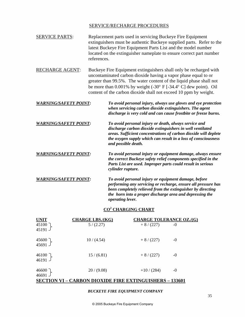
CO2 CHARGING CHART
UNIT CHARGE LBS./(KG) CHARGE TOLERANCE OZ./(G)45100 5 / (2.27) + 8 / (227) -045191
45600 10 / (4.54) + 8 / (227) -045691
46100 15 / (6.81) + 8 / (227) -046191
46600 20 / (9.08) +10 / (284) -046691SECTION VI – CARBON DIOXIDE FIRE EXTINGUISHERS – 133601
© 2005 Buckeye Fire Equipment Company
BUCKEYE FIRE EQUIPMENT COMPANY36
SERVICE/RECHARGE PROCEDURES
1. Completely empty and depressurize the extinguisher by removing the ring pin, aiming thenozzle in safe direction, and depressing the operating lever. It is highly recommended thisaction be done outdoors.
2. Verify that the nameplate is legible and faces outward.
3. Remove the hose and nozzle to examine for any abrasions, obstructions, butts, cracks, orthread damage. Verify it is the correct one for the specific model of extinguisher.
4. Perform a conductivity test on all 10, 15 and 20 lb. hose assemblies per NFPA-10recommendations. (Hose assemblies found to be nonconductive from the coupling shallbe replaced.) Label hose assemblies passing the conductivity test per NFPA-10recommendations.
5. On 10, 15 and 20 lb. models, inspect the diffuser hose to verify they are undamaged andunobstructed.
6. Thoroughly examine the extinguisher cylinder and components for any damage, corrosion,burns, repairs, or other physical conditions that might impair the extinguisher function.
NOTE: For additional inspection information pertaining to aluminumcompressed gas cylinders, refer to CGA Pamphlet C-6.1.
7. Check the date of manufacture stamped into the cylinder to determine if periodichydrostatic testing is necessary. Refer to the hydrostatic testing requirements on page 7.
NOTE: CO2 Hose Assemblies require hydrostatic testing at the same intervals ascylinders.
8. If hydrostatic testing or internal examination is NOT required, proceed to Step 18.
9. Remove the valve assembly from the cylinder with counterclockwise rotations.
NOTE: Ensure the original valve body and shell are kept together during serviceand recharge. These threads are not indexed and improper nameplateorientation may result from intermixing of components.
10. Thoroughly examine the cylinder internally for any corrosion, contaminates, or damage.
NOTE: If any worn or otherwise damaged thread surfaces are observed, BuckeyeFire Equipment recommends that the part be replaced.
SECTION VI – CARBON DIOXIDE FIRE EXTINGUISHERS – 133601
© 2005 Buckeye Fire Equipment Company
BUCKEYE FIRE EQUIPMENT COMPANY37
SERVICE/RECHARGE PROCEDURES (Cont.)
11. Remove the siphon tube and retainer nut from the valve body with counterclockwiserotations. Examine and replace if any damage or thread wear is evident.
12. Remove the valve stem and spring. Examine them for any damage or deformation.Remove and replace the valve stem o-ring with a new one.
13. Remove and replace the valve o-ring with a new one. Examine and clean the valve bodyseating surfaces with a damp cloth.
NOTE: Nicks, scratches, or residual contaminants left on valve seating surfacescan result in loss of pressure.
14. Remove the safety relief nut, washer, and disc assembly and replace with a new assembly.Install a new washer into the valve port followed by a safety disc and a safety relief nut.Torque the nut to 32 ft/lbs.
15. Reassemble the valve and siphon tube in the following order:
a) Lightly lubricate the o-rings and external metal threaded surfaces.
b) Using a finger, push the valve stem into the valve body until it is seated. Verify thatthe top portion of the stem extends beyond the valve body at least 3/8 inch.
c) Place the small end of the spring onto and over the stem post.
d) Push the threaded metal siphon tube or plastic siphon tube and adapter nut assemblyover spring and screw it into the valve body with firm clockwise rotations until secure.
e) Press the operating lever to verify there is proper movement.
f) Pull on the siphon tube to verify it is secure.
16. Screw the valve and siphon tube assembly into the cylinder with clockwise rotations.
NOTE: Normal valve body removal and installation only requires the use offirm hand pressure. Avoid the use of mallets as they may damagethread surfaces, handles, etc.
17. Examine the handle, operating lever, and rivets to verify that they are secure. Replace ifnecessary.
18. Install the correct Buckeye Fire Equipment Recharge Adapter on the extinguisher.(Buckeye Adapter P/N – 600004 for 5 lb. swivel diffuser model. Buckeye Adapter P/N –600003 for the 10, 15, and 20 lb. elbow diffuser models).
SECTION VI – CARBON DIOXIDE FIRE EXTINGUISHERS – 133601
© 2005 Buckeye Fire Equipment Company
BUCKEYE FIRE EQUIPMENT COMPANY38
SERVICE/RECHARGE PROCEDURES (Cont.)
WARNING/SAFETY POINT: To avoid personal injury, always use gloves and eye protectionwhen servicing carbon dioxide extinguishers. The agentdischarge is very cold and can cause frostbite or freeze burns.
WARNING/SAFETY POINT: To avoid personal injury or death, always service anddischarge carbon dioxide extinguishers in well ventilatedareas. Sufficient concentrations of carbon dioxide will depletethe oxygen supply and can result in a loss of consciousnessand possible death.
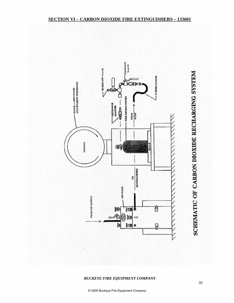
19. Using carbon dioxide meeting Buckeye Fire Equipment specifications, fill theextinguisher to the proper charge weight indicated on the nameplate and total weightstamped on the valve. Refer to the diagram on page 38 for a typical CO2 rechargingsystem. Follow the pump manufacturer’s recommendations for fill procedure.
20. When the desired weight is obtained, close the charging valve, open the bleed-off valve,and disconnect the recharge adapter from the extinguisher.
21. Install the pull pin through the extinguisher operating lever and valve body. Install atamper seal to secure the pull pin.
22. Test the extinguisher for leakage by either using commercially available solutions suchas Leak-Tek or by submerging the valve in a water bath for several minutes. (Anybubbles would indicate leakage. The unit should be properly depressurized and theservice/recharge procedures repeated.)
23. If no leakage is evident, reassemble the horn and/or hose assembly into the valve outletelbow diffuser.
24. Clean all dirt and foreign deposits from the extinguisher with a damp cloth.
25. Tag the extinguisher in accordance with NFPA-10 recommendations and record allnecessary information.
26. Return the extinguisher to its designated location.
© 2005 Buckeye Fire Equipment Company
BUCKEYE FIRE EQUIPMENT COMPANY39
SECTION VI – CARBON DIOXIDE FIRE EXTINGUISHERS – 133601
© 2005 Buckeye Fire Equipment Company
BUCKEYE FIRE EQUIPMENT COMPANY40
SECTION VII – WET CHEMICAL EXTINGUISHERS – 133301
WET CHEMICAL EXTINGUISHERS
Buckeye Fire Equipment 6 liter and 2-1/2 gallon Wet Chemical fire extinguishers have beenspecifically designed to combat fires in restaurant kitchen cooking appliances. The fireextinguishing agent is a potassium acetate / potassium citrate and water solution, the same liquidagent used in most kitchen fire suppression systems. Newer, more efficient cooking appliances,plus the use of non-saturated cooking oils require a fire extinguishing agent which will not onlysmother a fire but provide a cooling effect. This cooling effect is better realized with a WetChemical agent than with previously recommended dry chemicals.
These attractive, easy to use and maintain stainless steel extinguishers have a nondisruptive spraynozzle which limits the scattering of the burning material. There is no blinding cloud of chemical sothe user is able to apply the agent just where it is needed to extinguish the fire. Cleanup is quickerand easier since airborne particles do not spread to other areas.
MAINTENANCE PROCEDURES
DEFINITION: Maintenance is the thorough examination of the extinguisher and is intended toprovide maximum assurance that it will operate effectively and safely ifneeded. This examination will determine if hydrostatic testing is necessary andif the repair/replacement of serviceable items or recharge is in order. Ifnecessary, follow the applicable Buckeye Fire Equipment service/rechargeprocedures.
FREQUENCY: Maintenance of extinguishers NFPA-10 shall be performed at least annually orwhenever an inspection discrepancy dictates.
NOTES: Per NFPA-10, extinguishers out of service for maintenance shall be replacedby spare extinguishers of the same type and at least equal rating.
Maintenance should be performed by trained personnel using the proper tools,lubricants, and manufacturer’s recommended replacement parts. They shouldbe able to properly identify any indications of extinguisher damage or defectand safely correct such conditions per the applicable service/rechargeinstructions.
MAINTENANCE – SERVICE PROCEDURES
1. Clean the extinguisher to remove dirt, grease, or foreign material. Check to make sure that theinstruction nameplate is securely fastened and legible. Inspect the cylinder for corrosion,abrasion, dents, or weld damage. If any of these conditions are found and you doubt theintegrity of the cylinder, hydrostatically test it using the proof pressure method and a suitablecage, in accordance with CGA Pamphlet C-1 and NFPA Pamphlet 10.
© 2005 Buckeye Fire Equipment Company
BUCKEYE FIRE EQUIPMENT COMPANY41
SECTION VII – WET CHEMICAL EXTINGUISHERS – 133301 (Cont.)
MAINTENANCE – SERVICE PROCEDURES (Cont.)
NOTE: When cleaning, avoid the use of solvents around the pressure gauge.They could seriously damage the plastic gauge face.
2. Inspect the extinguisher for damaged, missing, or substitute parts. Only factory replacementparts are approved for use in Buckeye Fire Equipment extinguishers.
3. Weigh the extinguisher and compare with the weight printed in the Maintenance section of thenameplate (label). Recharge the extinguisher if the weight is not within the allowabletolerances.
4. Check the date of manufacture on the extinguisher nameplate. Cylinders must behydrostatically tested every 5 years to the test pressure indicated on the nameplate. BuckeyeFire Equipment recommends that the extinguishing agent be replaced with a new Buckeyecharge at the time of hydrostatic test. Refer to the hydrostatic testing requirements on page 7.
5. Visually inspect the pressure gauge:
a) If it is bent, damaged, or the wrong gauge, depressurize and replace.
b) If the pressure is low, check the unit for leaks.
c) If the unit is overpressurized (overcharged), invert the extinguisher and reduce thepressure to 50 PSI by depressing the operating lever. Quickly repressurize the unit to100 PSI to avoid liquid clogging the pressure valve. Check for leaks.
6. Inspect the footstand (base). If cracked or broken, replace with a proper footstand.
7. Check the pull pin for freedom of movement by breaking the seal and removing the pin.Replace the pull pin if it is bent or difficult to remove.
8. Inspect the operating lever for dirt or corrosion which might impair freedom of movement.Inspect the handle for proper installation. If the lever, handle, or rivets are damaged ordistorted, replace them with the proper Buckeye Fire Equipment replacement part(s).
9. Remove the hose/wand/nozzle assembly. Inspect the hose gasket (o-ring), hose/wand, andnozzle for damage. Replace as necessary. Blow air through the hose/wand/nozzle assembly toverify the passage is clear of foreign material.
© 2005 Buckeye Fire Equipment Company
BUCKEYE FIRE EQUIPMENT COMPANY42
SECTION VII – WET CHEMICAL EXTINGUISHERS – 133301 (Cont.)
MAINTENANCE – SERVICE PROCEDURES (Cont.)
10. Examine the pressurizing valve (Schrader) for damage. The cap should be in place to preventleaking. Inspect the valve assembly for corrosion or damage to the hose thread connections.Replace the valve assembly or component parts as necessary. Follow the properdepressurization and recharge procedures.
11. Reinstall the hose/wand assembly.
12. Install a new tamper seal and record the service data on the extinguisher inspection tag.
13. Re-hang the extinguisher on the wall hanger bracket. Verify that it fits the hanger bracketproperly. Replace the bracket if necessary.
RECHARGE
Recharging NFPA-10 is the replacement of the extinguishing agent and the expellant for this typeof extinguisher.
WARNING/SAFETY POINT:
a) Before attempting to recharge, be sure this extinguisher is completelydepressurized.
b) Use a regulated pressurizing source (either air or Nitrogen). Set the regulator tono more than 25 PSI higher than the gauge operating pressure.
c) Check and calibrate the regulator gauge at frequent intervals. The regulatorgauge should be used to determine when the intended charging pressure has beenreached. Do not use the extinguisher gauge for this purpose.
d) Never leave an extinguisher connected to a regulator of a high pressure source foran extended period of time. A defective regulator could cause the cylinder torupture from excessive pressure.
RECHARGING PROCEDURES
1. Complete the “Maintenance – Service Procedure”, Item 1 thru 10.
2. Discharge all remaining pressure and wet chemical solution. Make sure that there is noremaining air pressure.
© 2005 Buckeye Fire Equipment Company
BUCKEYE FIRE EQUIPMENT COMPANY43
SECTION VII – WET CHEMICAL EXTINGUISHERS – 133301 (Cont.)
3. Remove the valve assembly. Disassemble it by removing the siphon tube assembly (use awrench on the brass retainer, not the plastic tube), spring and valve stem from the valveassembly. Remove the collar o-ring from the valve assembly.
RECHARGING PROCEDURES (Cont.)
4. Thoroughly rinse all parts with clean water and wipe dry with a soft cloth. Blow the valve outwith air or nitrogen. Inspect the collar o-ring, valve steam, and spring. Replace parts if wornor damaged. Lightly lubricate the collar o-ring and small o-ring on the valve stem withVisilox V-728 (DO NOT LUBRICATE THE VALVE STEM SEAL). Inspect the siphon tube.If cracked or deformed, replace with the proper tube (see parts list). Inspect the siphon tube o-ring and replace if necessary.
5. Rinse the cylinder with clean water and inspect the interior following CGA Visual InspectionStandard, Pamphlet C-6.
6. Carefully follow the solution mixing instructions on the charge carton.
7. Reinstall the valve assembly to the cylinder and properly align.
CAUTION: Hand-tighten the valve collar nut (100-125 in. – lbs. max.).Overtightening with a wrench will damage the valve.
8. Remove the cap from the pressurizing valve (Shrader) on side of the valve body andpressurize the extinguisher to 100 PSI with air or nitrogen. The pressure regulator should beset to no more than 125 PSI. After pressurization is complete reinstall the pressure valve cap.The cap must be in place to ensure that valve will not leak.
9. Check the collar, gauge, pressurizing valve, cylinder welds, and valve orifice for leaks usingleak detection fluid or a solution of soapy water. Remove the leak detection fluid from thevalve assembly by blowing it out with air. Wipe the exterior of the extinguisher dry. (If gaugereplacement is necessary, refer to page 56.)
10. Reinstall the hose and nozzle/wand assembly.
11. Reinstall the pull pin (the ring should face the front of the extinguisher). Install a new tamperseal. Record the recharge date and attach a new recharge tag to the extinguisher.
12. Weigh the assembled extinguisher and confirm that the total weight is within the allowabletolerances indicated on the Maintenance section on the extinguisher nameplate (label).
13. Return the extinguisher to its designated location.
© 2005 Buckeye Fire Equipment Company
BUCKEYE FIRE EQUIPMENT COMPANY44
SECTION VIII – WATER EXTINGUISHERS – 133701
Buckeye Fire Equipment 2-1/2 gallon Water and Water Mist fire extinguishers are designed tocombat Class A fires (common combustibles – wood, paper, trash). Both the Water and Water Mistextinguishers provide a clean, environmentally friendly, inexpensive, and readily availableextinguishing agent whose extinguishing properties are universally understood. Water is theextinguishing agent of choice for novice and professional firefighters alike. The extinguishers areconstructed of attractive and easy to maintain stainless steel and are equipped with discharge hoseassemblies that allow the user to maintain a safe distance from the fire while accurately applyingthe agent.
MAINTENANCE PROCEDURES
DEFINITION: Maintenance is the thorough examination of the extinguisher and is intended toprovide maximum assurance that it will operate effectively and safely whenneeded. This examination will determine if hydrostatic testing is necessary andif the repair/replacement of serviceable items or recharge is in order. Ifnecessary, follow the applicable Buckeye service/recharge procedurescontained in this Section.
FREQUENCY: Maintenance of extinguishers NFPA-10 shall be performed at least annually orwhenever an inspection discrepancy dictates.
NOTES: Per NFPA-10, extinguishers taken out of service for maintenanceshall be replaced by spare extinguishers of the same type and of atleast equal rating.
Trained personnel using the proper tools, lubricants, andmanufacturer recommended replacement parts should performmaintenance. They should be able to identify any indications ofextinguisher damage or defect and be able to safely correct suchconditions per the applicable service/recharge instructions.
MAINTENANCE – SERVICE PROCEDURES
1. Clean the extinguisher to remove dirt, grease, or foreign material. Check to make sure that theinstruction nameplate is securely fastened and legible. Inspect the cylinder for corrosion,abrasion, dents, or weld damage. If any of these conditions are found and you doubt theintegrity of the cylinder, hydrostatically test the unit using the proof pressure method and asuitable cage, in accordance with CGA Pamphlet C-1 and NFPA Pamphlet 10.
NOTE: When cleaning the extinguisher avoid the use of solvents around the pressure gauge.Solvents can seriously damage the plastic gauge face.
© 2005 Buckeye Fire Equipment Company
BUCKEYE FIRE EQUIPMENT COMPANY45
SECTION VIII – WATER EXTINGUISHERS – 133701 (cont.)
2. Inspect the extinguisher for damaged, missing, or substitute parts. Only factory replacementparts are approved for use on Buckeye extinguishers.
3. Weigh the extinguisher and compare the weight with the required weight printed in theMaintenance Section of the nameplate (label). Recharge the extinguisher if the weight is notwithin the indicated allowable tolerance.
4. Check the date of manufacture on the extinguisher nameplate. The cylinder is required to behydrostatically tested every 5 years to the test pressure printed on the nameplate. Buckeye FireEquipment recommends that the extinguishing agent be replaced with a new Buckeye charge atthe time of hydrotesting. Refer to the hydrostatic testing requirements on page 7.
5. Visually inspect the pressure gauge:a) If it is bent, damaged, or improperly installed – depressurize the extinguisher and replace the
gauge.b) If the pressure is low – check for leaks.c) If overpressurized (overcharged) – invert the extinguisher and reduce the pressure to 50 PSI
by depressing the operating lever. Quickly repressurize the unit to 100 PSI to avoid liquidclogging the valve. Check for leaks.
6. Check the pull pin for freedom of movement by breaking the tamper seal and removing the pin.Replace the pull pin if it is bent or difficult to remove.
7. Inspect the operating lever for dirt or corrosion that could impair its freedom of movement.Inspect the carrying handle for proper installation. If the lever, handle, or rivets are damaged ordistorted, replace with the authorized Buckeye replacement part(s).
8. Remove the hose/wand discharge assembly and inspect each part for damage (including thedischarge assembly o-ring). Replace as necessary. Blow air through the assembly to ensurethat the passage is clear of obstructions and foreign materials.
9. Examine the pressurizing valve (Schrader Valve) for damage. The cap should be in place orpressure leakage will occur. Inspect the valve assembly for corrosion and damage. Payparticular attention to the thread connection for the discharge assembly. Replace the valveassembly or component parts as necessary. Be sure to follow the proper depressurization andrecharge procedures.
10. Reinstall the hose/wand assembly.
11. Reinstall the pull pin and install a new tamper seal.
12. Record the service data on the extinguisher inspection tag and return the extinguisher to itsdesignated location. Make sure the extinguisher is oriented so that the nameplate is facingoutward.
SECTION VIII – WATER EXTINGUISHERS – 133701 (cont.)
© 2005 Buckeye Fire Equipment Company
BUCKEYE FIRE EQUIPMENT COMPANY46
13. Verify that the securing/mounting hardware is in proper working order and is the properhardware for the extinguisher.
RECHARGE
Recharging NFPA-10 4 is the replacement of the extinguishing agent, including the expellant forthis type of extinguisher.
WARNING/SAFETY POINT: a) Before attempting to recharge an extinguisher besure it is completely depressurized.
b) Use a regulated pressurizing source (nitrogen).Set the regulator to no more than 25 psi higherthan the gauge operating pressure.
c) Check and calibrate the regulator gauge at
frequent intervals. The regulator gauge shouldbe used to determine when the intended chargingpressure has been reached. Do Not use theextinguisher gauge for this purpose.
d) Never leave an extinguisher connected to aregulator of a high-pressure source for anyextended period. A defective regulator couldcause the cylinder to rupture because of excessivepressure.
RECHARGING PROCEDURES
1. Complete the “MAINTENANCE-SERVICE PROCEDURE”, Items 1 thru 10.
2. Discharge all remaining pressure and water. Be certain that there is no remaining air pressure.
3. Remove the valve assembly and disassemble it by removing the siphon tube assembly (usinga wrench on the brass retainer - Do not wrench on the plastic), spring, and valve stem.Remove the collar o-ring from the valve assembly.
4. Thoroughly rinse all parts with clean water and wipe dry with a soft cloth. Blow the valve outwith air or nitrogen. Inspect the collar o-ring, valve stem, and spring. Replace any parts thatshow signs of wear or damage. Lightly lubricate the collar o-ring and the small o-ring on thevalve stem with Visilox V-728 (DO NOT lubricate the valve stem seal). Inspect the siphontube for cracks or deformations. Replace with an authorized replacement tube as necessary.Inspect the siphon tube o-ring, replace if necessary.
5. Rinse the cylinder with clean water and inspect the interior of the cylinder per the CGA visualinspection standard, Pamphlet C-6.
© 2005 Buckeye Fire Equipment Company
BUCKEYE FIRE EQUIPMENT COMPANY47
SECTION VIII – WATER EXTINGUISHERS – 133701 (cont.)SECTION VIII – WATEREXTINGUISHERS – 133701 (cont.)
6. Fill the extinguisher with 2-1/2 gallons of water (deionized water is used for the Water Mistextinguisher).
7. Reinstall the valve assembly on the cylinder making certain to properly align the gauge facewith the nameplate.
CAUTION: Hand-tighten the valve collar nut (100 – 125 in. lbs. max). Overtightening with awrench will damage the valve.
8. Remove the cap from the air pressurizing valve on the side of the valve body and pressurizewith 100 psi of nitrogen. The pressure regulator should be set a no more than 125 psi.Replace the pressure valve cap when pressurizing is complete. The cap must be in place toassure that the valve will not leak.
9. Check the collar, gauge, air pressurizing valve, cylinder welds, and valve for leaks. Use aleak detection fluid or a solution of soapy water. Remove leak detection fluid from the valveassembly by blowing it out with air. Wipe the exterior of the extinguisher dry. If gaugereplacement is necessary, refer to the service illustrations and diagrams in Section IX.
10. Reinstall the hose/wand assembly.
11. Reinstall the pull pin (ring end positioned on the gauge side). Install a new tamper seal.Record the recharge date and attach the recharge tag.
12. Weigh the assembled extinguisher and verify that it is within the weight tolerance printed inthe Maintenance Section of the nameplate.
13. Return the extinguisher to its designated location.
© 2005 Buckeye Fire Equipment Company
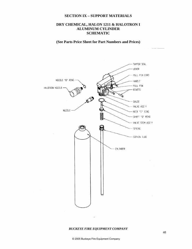
BUCKEYE FIRE EQUIPMENT COMPANY48
SECTION IX – SUPPORT MATERIALS
DRY CHEMICAL, HALON 1211 & HALOTRON IALUMINUM CYLINDER
SCHEMATIC
(See Parts Price Sheet for Part Numbers and Prices)
© 2005 Buckeye Fire Equipment Company
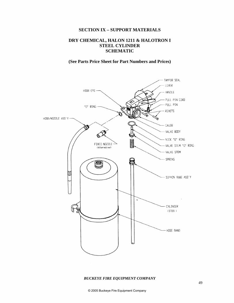
BUCKEYE FIRE EQUIPMENT COMPANY49
SECTION IX – SUPPORT MATERIALS
DRY CHEMICAL, HALON 1211 & HALOTRON ISTEEL CYLINDER
SCHEMATIC
(See Parts Price Sheet for Part Numbers and Prices)
© 2005 Buckeye Fire Equipment Company
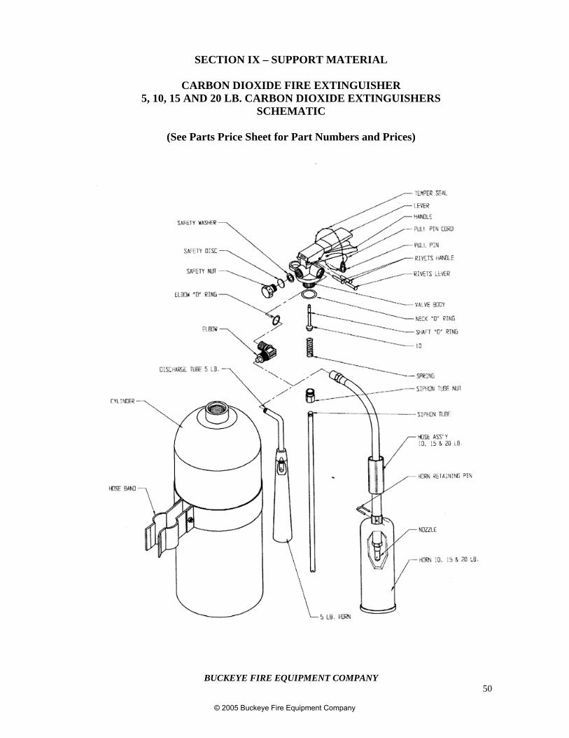
BUCKEYE FIRE EQUIPMENT COMPANY50
SECTION IX – SUPPORT MATERIAL
CARBON DIOXIDE FIRE EXTINGUISHER5, 10, 15 AND 20 LB. CARBON DIOXIDE EXTINGUISHERS
SCHEMATIC
(See Parts Price Sheet for Part Numbers and Prices)
© 2005 Buckeye Fire Equipment Company
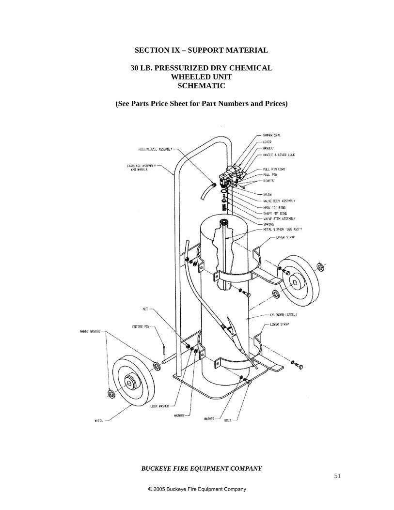
BUCKEYE FIRE EQUIPMENT COMPANY51
SECTION IX – SUPPORT MATERIAL
30 LB. PRESSURIZED DRY CHEMICALWHEELED UNIT
SCHEMATIC
(See Parts Price Sheet for Part Numbers and Prices)
© 2005 Buckeye Fire Equipment Company
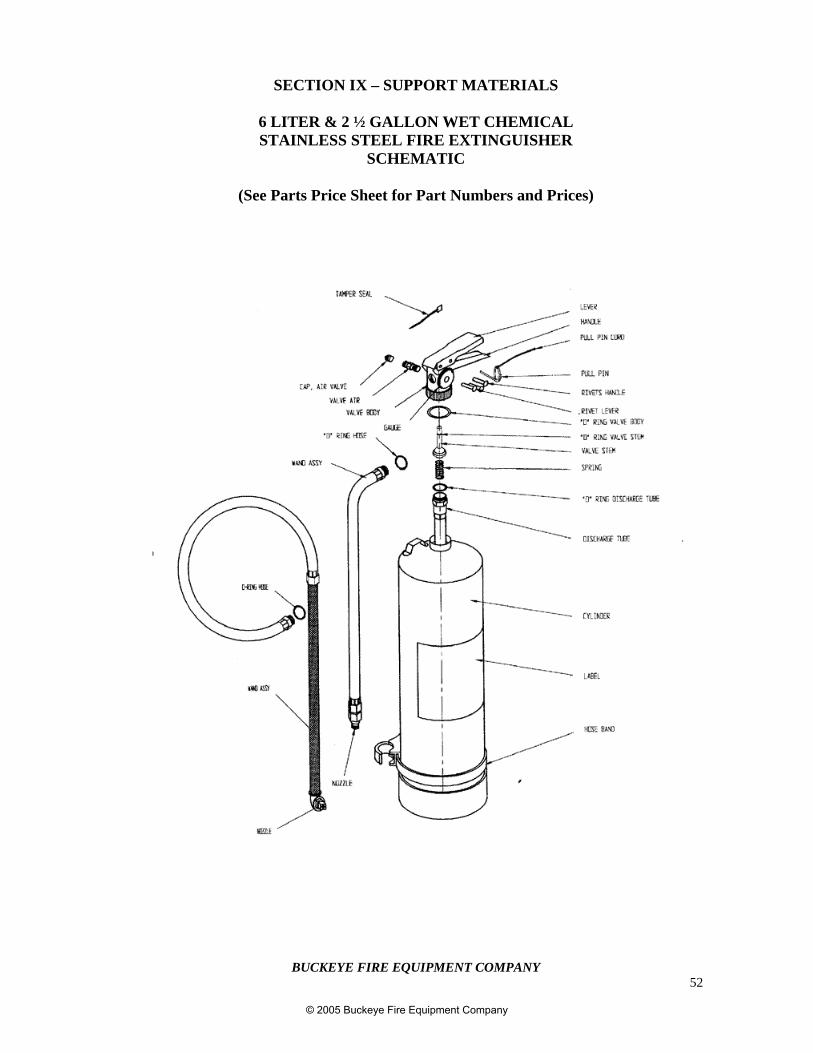
BUCKEYE FIRE EQUIPMENT COMPANY52
SECTION IX – SUPPORT MATERIALS
6 LITER & 2 ½ GALLON WET CHEMICALSTAINLESS STEEL FIRE EXTINGUISHER
SCHEMATIC
(See Parts Price Sheet for Part Numbers and Prices)
© 2005 Buckeye Fire Equipment Company
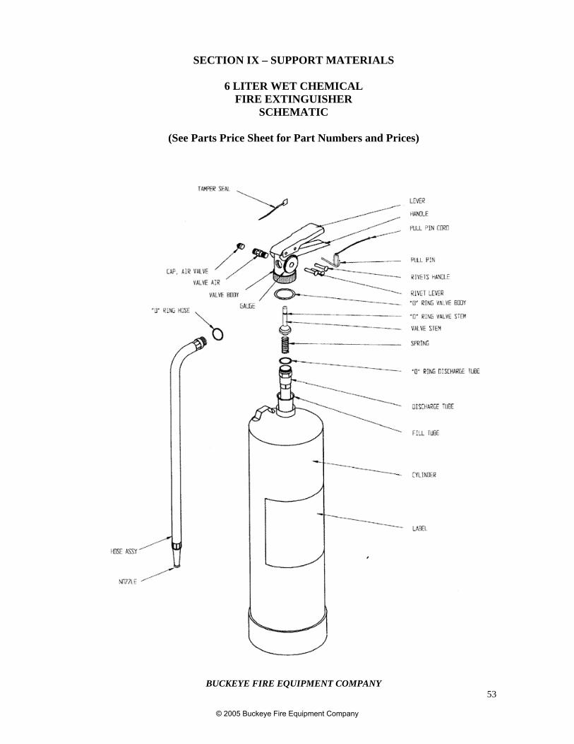
BUCKEYE FIRE EQUIPMENT COMPANY53
SECTION IX – SUPPORT MATERIALS
6 LITER WET CHEMICALFIRE EXTINGUISHER
SCHEMATIC
(See Parts Price Sheet for Part Numbers and Prices)
© 2005 Buckeye Fire Equipment Company
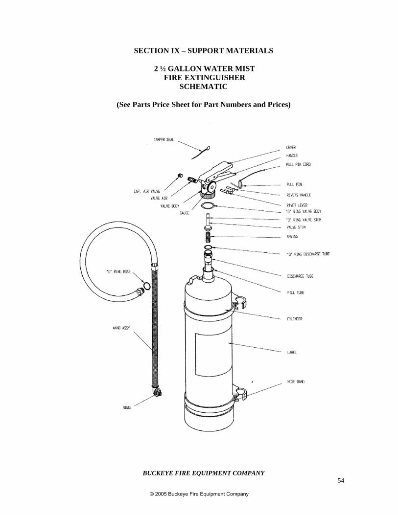
BUCKEYE FIRE EQUIPMENT COMPANY54
SECTION IX – SUPPORT MATERIALS
2 ½ GALLON WATER MIST FIRE EXTINGUISHER
SCHEMATIC
(See Parts Price Sheet for Part Numbers and Prices)
© 2005 Buckeye Fire Equipment Company
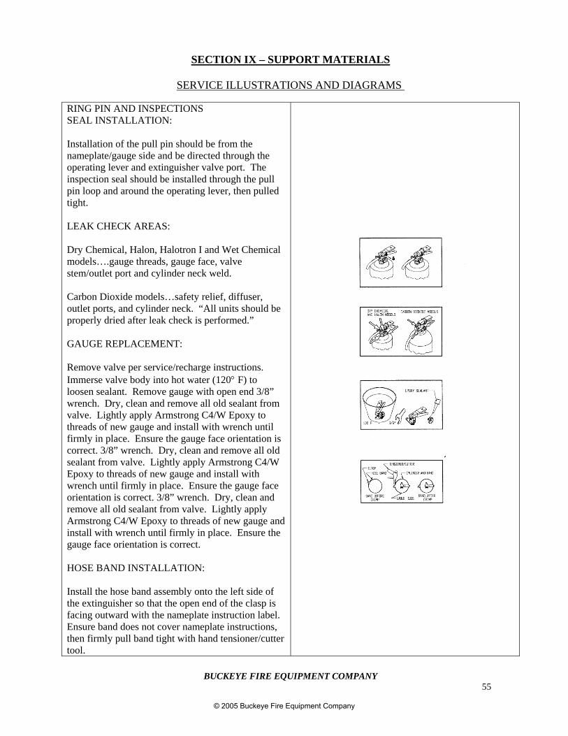
BUCKEYE FIRE EQUIPMENT COMPANY55
SECTION IX – SUPPORT MATERIALS
SERVICE ILLUSTRATIONS AND DIAGRAMS
RING PIN AND INSPECTIONSSEAL INSTALLATION:
Installation of the pull pin should be from thenameplate/gauge side and be directed through theoperating lever and extinguisher valve port. Theinspection seal should be installed through the pullpin loop and around the operating lever, then pulledtight.
LEAK CHECK AREAS:
Dry Chemical, Halon, Halotron I and Wet Chemicalmodels….gauge threads, gauge face, valvestem/outlet port and cylinder neck weld.
Carbon Dioxide models…safety relief, diffuser,outlet ports, and cylinder neck. “All units should beproperly dried after leak check is performed.”
GAUGE REPLACEMENT:
Remove valve per service/recharge instructions.Immerse valve body into hot water (120° F) toloosen sealant. Remove gauge with open end 3/8”wrench. Dry, clean and remove all old sealant fromvalve. Lightly apply Armstrong C4/W Epoxy tothreads of new gauge and install with wrench untilfirmly in place. Ensure the gauge face orientation iscorrect. 3/8” wrench. Dry, clean and remove all oldsealant from valve. Lightly apply Armstrong C4/WEpoxy to threads of new gauge and install withwrench until firmly in place. Ensure the gauge faceorientation is correct. 3/8” wrench. Dry, clean andremove all old sealant from valve. Lightly applyArmstrong C4/W Epoxy to threads of new gauge andinstall with wrench until firmly in place. Ensure thegauge face orientation is correct.
HOSE BAND INSTALLATION:
Install the hose band assembly onto the left side ofthe extinguisher so that the open end of the clasp isfacing outward with the nameplate instruction label.Ensure band does not cover nameplate instructions,then firmly pull band tight with hand tensioner/cuttertool.
© 2005 Buckeye Fire Equipment Company
BUCKEYE FIRE EQUIPMENT COMPANY56
MAIN OFFICE110 Kings Road
Kings Mountain, North Carolina 28086-0428Phone 704.739.7415
Fax 704.739.7418
SALES / WAREHOUSE LOCATIONS
ILLINOIS65 East Palantine RoadSuite 211Prospect Hts., IL 60070800.528.3173847.541.3886Fax: 847.541.3879
DALLAS, TX 1170 Corporate DriveSuite 201Arlington, TX 76006817.633.3626877.391.3626Fax: 817.633.5884
FLORIDA3146 John P. Curci DriveBldg. 3A/Bay 4Pembrook Park, FL 33009954.966.9859Fax: 954.966.8351
NEW JERSEY24 Worlds Fair DriveSuite ESomerset, NJ 08873732.560.8149Fax: 732.560.3591
HOUSTON, TX6226 Brookhill DriveHouston, TX 77087800.752.1274713.645.3388Fax: 713.645.3387
GARY NARKSOlde River Yacht Club4900 Whiskey IslandCleveland, OH 44102888.344.1103Fax: 216.281.4204
JON DUNHAM4072 S.W. NormadyLee’s Summitt, MO 64082816.537.6482Fax: 816.537.6483
TIM POTTSPMB 3021720 Mars Hill Road #8Acworth, GA 30101770.499-1538Fax: 770.499.0477
© 2005 Buckeye Fire Equipment Company

BUCKEYE FIRE EQUIPMENT COMPANY57
© 2005 Buckeye Fire Equipment Company