weight reduction analysis of a 90 mm water cannon - angelfire · weight reduction analysis of a 90...
TRANSCRIPT

Technical Report ARAEW-TR-04004
WEIGHT REDUCTION ANALYSIS OF A 90 MCANNON
David C. Smith, G. Peter O’Hara, Daniel CAndrew Littlefield, Martin Leach
APRIL 2004
APPROVED FOR PUBLIC RELEASE; DISTRIBUTION U
D
ARMAMENT RESEARCH, DEVELOPMENT AND ENGINEERINArmaments Engineering & Technology Center
Weapon Systems & Technology Benét Laboratories
Watervliet, New York
A
M WATER
ler,
NLIMITED
G CENTER

The views, opinions, and/or findings contained in this report are those of the author(s) and should not be construed as an official Department of the Army position, policy, or decision, unless so designated by other documentation. The citation in this report of the names of commercial firms or commercially available products or services does not constitute official endorsement by or approval of the U.S. Government. Destroy this report when no longer needed by any method that will prevent disclosure of its contents or reconstruction of the document. Do not return to the originator.
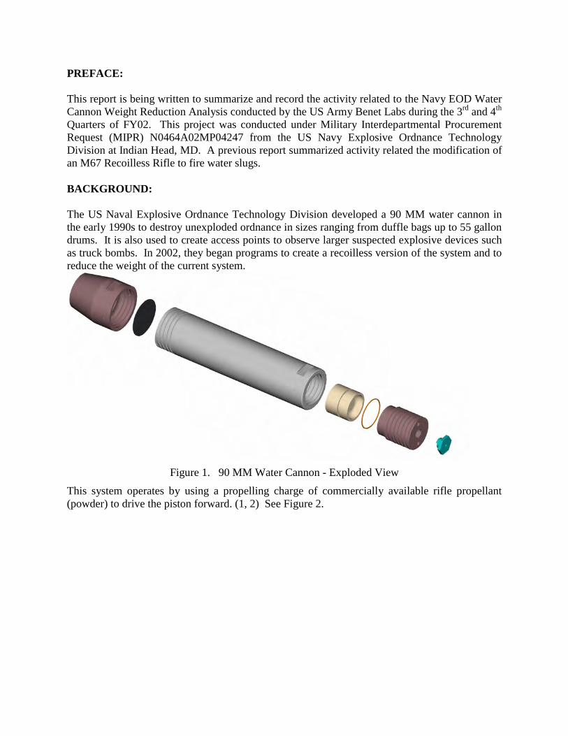
PREFACE: This report is being written to summarize and record the activity related to the Navy EOD Water Cannon Weight Reduction Analysis conducted by the US Army Benet Labs during the 3rd and 4th Quarters of FY02. This project was conducted under Military Interdepartmental Procurement Request (MIPR) N0464A02MP04247 from the US Navy Explosive Ordnance Technology Division at Indian Head, MD. A previous report summarized activity related the modification of an M67 Recoilless Rifle to fire water slugs. BACKGROUND: The US Naval Explosive Ordnance Technology Division developed a 90 MM water cannon in the early 1990s to destroy unexploded ordnance in sizes ranging from duffle bags up to 55 gallon drums. It is also used to create access points to observe larger suspected explosive devices such as truck bombs. In 2002, they began programs to create a recoilless version of the system and to reduce the weight of the current system.
Figure 1. 90 MM Water Cannon - Exploded View
This system operates by using a propelling charge of commercially available rifle propellant (powder) to drive the piston forward. (1, 2) See Figure 2.

Figure 2. Section View of Water Cannon
The diaphragm quickly bursts and the water is propelled at extreme velocity through the nozzle. PROGRAM OBJECTIVES: The program objectives, as agreed between EOD Technology Division and Benet Labs (3) were: a. Develop an interior ballistic analysis showing a pressure-time curve of the existing propelling charge and a prediction of impulse. Note that this would be reliant on adaptation of existing recoilless rifle models to address a water slug rather than a solid projectile. b. Based on use of other propellants – repeat analysis and recommend alternatives. Note that this will require customer input on desired characteristics, such as muzzle velocity, weight, etc. to establish ranking.
c. Develop an Elastic Strength Pressure (ESP) limit of the existing water cannon using numerical models developed by Benét Labs.
d. Review existing high strength materials and composites for potential application to the future design.
e. Recommend high-level design alternatives for consideration in the future design based on the findings above, and our knowledge of cannon design in general. ANALYSIS: Elastic Strength Pressure:
WATER CAVITY
PROPELLANT
.50 CAL CARTRIDGEDIAPHRAM
NOZZLE
WATER CAVITY
PROPELLANT
.50 CAL CARTRIDGEDIAPHRAM
NOZZLE
PISTON

The Elastic Strength Pressure (ESP) limit of the Tube (EOD-X-99005) was determined using the TUBES code resident at Benet Labs and an evaluation of the material properties. Note that this tube is considered a relatively thick wall tube and is not autofrettaged. The results of this analysis are shown in Figure 3. Two (2) additional weight reduction options were considered along with the base case (52 lbs).
The legend cites the yield strength of the material and the approximate tube total weight. Figure 4 shows the two optional configurations, with the forward threads ignored. The baseline material from the EOD-X-99005 drawing is 4140 Steel with a yield strength of 210 ksi. While this material may have a high yield strength, it is very brittle, with a Charpy Impact of approximately 4 ft-lbs. Hence, when the material fails it will be very quick and without warning. Original ballistics data delivered from the Navy indicated a peak internal pressure of 7.5 ksi. Our analysis indicates that pressures could be higher based on certain factors, such as dynamic motions and mis-weighed propellant. Our Pressure Travel analysis is discussed in the section on Interior Ballistics, and the curve is shown on Figure 3 for comparison to the various options studied. A safety margin of 1.5 ksi was selected to ensure sufficient margin of safety in pressure containment, with a final desired containment of 15 ksi in the area just forward of the threads. Based on these material properties and the dimensions cited on drawing 99005, the pressure containment of the current system is as shown on Figure 3 as 210-52 lbs (legend is material yield
0
10,000
20,000
30,000
40,000
50,000
60,000
70,000
0 5 10 15 20
Distance from Rear Face of Tube (RFT) (inches)
Elastic Strength Pressure (psi)
210 52lbs
210 19lbs
160 52lbs
160 19lbs
160 22lbs
Pressure Travel
Figure 3. Elastic Strength Pressure of Water Cannon.

in ksi and weight). Reducing the wall thickness of the tube, with the exception of the breech-end, the tube can be reduced to a desired weight of 19 lbs, and the tube can still hold the desired 15 KSI, as shown on the curve labeled 210 ksi-19 lbs.
Figure 4. Alternative Profiles – Lower = 19 lbs – Upper = 22 lbs.
Since the 4140 Steel is very brittle, other steels were considered. When a 4340 Steel fails it is more graceful and will produce a warning (elongation) before the point of failure. Using the original dimensions, the pressure containment of the tube was evaluated using a relatively ductile (Charpy Impact 15 ft-lbs) 4340 Steel is shown in curve 160-52 lbs. Next, the same material in a 19 lbs configuration was evaluated (curve 160-19lbs). As can be seen in the curve, the pressure containment is limited to approximately 11 KSI, and was considered inadequate. However, if the wall thickness is increased to the desired pressure containment of 15 ksi, the weight of the tube will be 22 lbs, as shown in curve 160-22lbs, using this 4340 steel. This alloy and heat treatment are readily available and well known. Given tolerancing and other considerations (fillets, threads), a weight savings of 28 lbs can be expected.

Further advances could be made by examining other alloys available. The 81 MM M253 Mortar Tube utilizes a non-autofrettaged tube design and has a pressure range similar to the one cited above. This component uses steel bar per AMS 6484, 6415 or 6414, with a minimum yield strength of 160 ksi, Ra 30% minimum, Charpy impact energy of 18 ft lbs minimum. These alloys are not always readily available, however, except for volume purchases. Since the machining and heat treatment processes are primarily the same, no significant cost differences should occur by altering the geometry slightly, changing the material and adjusting the heat treat process. Interior Ballistics: The interior ballistics were analyzed using NOVA code (7), a modern ballistics code that has been proven very accurate. Some extra effort was required to determine the parameters of the propellant used, however, the analysis appears to be very accurate. The pressure travel curve is shown above in Figure 3. Figure 5 shows the pressure time curve for the system. It should be noted that the hump in the curve at the beginning of the ballistic cycle is the .50 caliber initiator. Given its large energy level with respect to the main propellant mass, it is more noticeable than traditional initiators that have a much smaller relative energy. Finite Element Analysis: This analysis used the existing design and examined both a static internal pressure and maximum pressure-travel curve based on the interior ballistics analysis. Figure 6 shows the results of this static analysis with the deflection exaggerated. Maximum stress is calculated as 55,740 psi.

Figure 5. Pressure Time Curve for 90 MM Water Dragon.
0
2
4
6
8
10
12
14
16
0 0.001 0.002 0.003 0.004 0.005
Time (secs)
Pressure (ksi)

Figure 6. Stresses in 90 MM Water Dragon for internal pressure of 7500 psi.
Further analysis was done with the pressure time curve and including the support effects of the nozzle at the end of the tube where worst stresses were found. A snapshot of these stresses are shown in Figure 7. The entire tube snapshot is shown in the inset. The nozzle support effect is included, but the nozzle is not shown. Peak stresses are very similar to the static figures. Significant stress oscillations were noted during this analysis.

Figure 7. Detailed View of Dynamic FEA results at Nozzle End of Tube.
Composite Analysis: After performing a finite element analysis on the all steel tube the maximum axial and hoop stresses were identified. The composite laminate was designed using these stresses and classical laminated plate theory. No reduction in strength from the original design was made. To use this theory the stresses were transformed into in-plane loadings of 2300 lb/in in the hoop direction and 600 lb/in in the axial direction. The PC-Laminate computer code was used to generate properties of potential candidate “lay-ups” and apply these loadings to them. Laminate strains and curvatures are calculated and the laminate was checked for failure against the Tsai-Wu Polynomial and the Maximum Stress Criterion. This process was conducted for both carbon fiber and fiberglass reinforced laminates. The carbon fiber laminate produces the lightest and stiffest solution but at increased cost. The fiberglass solution produces the cheapest solution but at a loss of performance. For the carbon fiber solution IM-7 was chosen as we currently have worked with IM-7 in pressure vessels. The lay-up selected is an 8 ply cross-play laminate: (90/90/0/0). This solution should save approximate 28 lbs of weight. For the fiberglass solution generic s-glass properties were used. This lay-up was considered to be wet wound instead of autoclave cured to save on cost so only average properties would be achieved. The layup selected in this case is a 30 ply cross-ply laminate: (90/90/90/90/0/90/90/90/90/0/90/90/90/90/0)s. This approach would save about 25 pounds of weight.

Costs for the carbon fiber prepreg assume a tow configuration. This combined with a 3 times wastage rate should account for other materials, such as bagging plastic, that must be used. Recent similar products have cost about $ 2700 for curing in the Watervliet Arsenal autoclave. Table 1 summarizes the cost estimate.
It may be possible to cure tubes of this size in the Benet autoclave but it would necessitate separate cure cycles so we are unsure if there would be a cost savings. For wet winding with glass we estimated the material costs at $15 per pound and used twice the amount of material in the each tube, to account for wastage and replacement of used materials. Since the glass would be wet wound using room temperature curing resins there is no autoclave cure to charge for. This may make the part heavier than predicted but it is cheaper. In both cases it assumed that the composite would be the load bearing material and the steel is simply there as a barrier between the composite and the bore. The thickness of the steel was assumed to 1/8". A thinner section of steel could be used to achieve additional weight savings but the steel must be thick enough to maintain its shape while being handled during the fabrication process. Additionally it would advisable to have the steel finished in a roughened or even threaded surface in the area where the composite will be located. This would help with adhesion and transfer of loading from the steel to the composite. The length of the composite was assumed as a right circular tube, inner diameter about .125” greater than the current bore, outer diameter about 5.1”, length assumed to be 13.75". This was based on a minimum estimate of the chamber length subjected to extreme pressures from the tube (EOD-X-99005). If this length is not available the amount of weight savings will of course not be realized. Also the outer steel diameter under the composite should be tapered from the outer steel diameter on either side of the overwrap. This will also slightly reduce the amount of weight savings that can be achieved. Extending the composite over the chamber plug zone would offset this effect. A protective overwrap of glass would probably be added to either
Activity People Time
(days) per hour curing material for 2 tubes
Layup: 2 3 91$ 488$ 5,413$
Curing: 1 0.5 91$ 2,700$ 3,110$
8,523$
Layup: 2 3 91$ 170$ 5,094$
Curing: 0 0 91$ -$ -$
5,094$ Fiberglass Option
Cost
Carbon Fiber Option
Table 1. Cost Estimate to Fabricate 2 Composite Water Cannon Tubes.

design. The resultant concept is shown at Figure 8. The interior dimensions remain the same, and the overall outer diameter would be 5.1”.
Figure 8. Composite Tube Concept Cross Section.
Both of these designs should be taken as preliminary and a full FEA analysis should be performed before either of them is produced. This analysis would ensure that the stiffness of the system has not been compromised and that there are no additional dynamic loadings that could cause the laminate to fail. Computational Fluid Dynamics: The previous report detailed the analysis of the fluid slug being propelled and ejected from a 90 MM M67 Recoilless Rifle. An examination of the pressure travel curve of these two (2) systems indicates that the interior ballistics is very similar with the exception of the travel distance in-bore and the related acceleration period. The computational fluid dynamic analysis of this system would reveal nothing new. As such, no separate analysis of this system was performed. Technical Design Recommendations: Practical experience with cannon design indicates that stub acme threads are not the best choice for a threaded interface with the cannon system. Stub acme threads are typically not used where any degree of precision or close fit are required (ref 5), since it is intended for coarse fits. Additionally, the angle of the thread will generate high radial forces for high axial forces. Thorough research at Benet Lab (ref 6) developed a special threadform that balances fatigue considerations and radial force, now known commonly as the Benet Standard Buttress Threadform. This standard is not widely known and is not necessary for this application, where fatigue is not a primary consideration. There are several standard buttress threadforms in common use, that are good alternatives, including:
• American Society of Mechanical Engineers (ASME) B1.9 7°/45° Buttress Inch Screw Thread Revised 2000 (formerly American National Standards Institute (ANSI) B1.9-1973 7°/45° Buttress Inch Screw Thread)

• Society of Automotive Engineers (SAE) Metric Aerospace (MA) 1696 Screw Threads, Metric Buttress – MJB Profile
• Deutsches Institut Fur Normung (DIN) 513 Metric Buttress Threads This system, when fired, has the potential to generate high temperature steam and high stress at the interior walls. High strength steel alloys, when subjected to these conditions, could be affected by hydrogen embrittlement, which has a detrimental effect on fatigue and material properties. Regardless of what other alternative design approaches are considered, coating of this bore is advisable. Chrome plating is a common approach and is commercially available. Nickel plating, or nickel strikes to chrome, must be carefully examined, since the acid etch pre-treatment commonly used, can hydrogen embrittle the steel. Given that fatigue is not a primary concern, this may be acceptable. Nitriding processes are also commonly used in medium caliber cannons. Conclusions and Recommendations The basic conclusions and recommendations for the 90 MM Water Cannon (Dragon) are as follows:
1. The current stress levels in the system are very low, indicating a high degree of safety and overdesign.
2. The recommended path forward with an all steel tube would be to proceed with a 4340 Steel designed to the desired internal pressure containment, with suitable safety margin, as shown Figure 3. Recommended steel condition to be minimum yield strength 160 ksi, Charpy impact 15 ft lbs minimum. This should result in a system with adequate safety margin with less chance for catastrophic failure. A weight savings of 28 lbs could be achieved with little or no change in the fabrication cost of the system.
3. The recommended path forward for a composite tube would be to re-analyze the system to optimize the pressure containment required and ensure that the composite lay-up is not over-designed. A minimum weight savings of 25-28 lbs could be achieved for fabrication costs of $2,500 - $4,000 per system in a prototype mode. Further weight savings could be realized for more analysis and optimization.
4. Review the thread engagement and shear areas on the nozzle and breech thread. 5. Recommend changing the threadform on the nozzle and breech plug to the ASME B1.9
Buttress Inch Screw Threads. 6. Recommend chrome plating the bore to SAE AMS QQ-C-320 Class 2, Type I or II, shot
peening not required. (formerly Federal Standard QQ-C-320, Class 2A).

REFERENCES: [1] Meeting, 13 Jun 02, Naval Ordnance Disposal Technology Division, Indian Head, MD, subject: Weight Reduction of 90 MM Water Cannon (Dragon). [2] Water Cannon Assembly, 90 MM Naval Ordnance Disposal Technology Division Drawing EOD-X-99004. [3] Memo, AMSTA-AR-CCB-DC, 27 June 2002, subject: Costs and Proposed Work Related to Weight Reduction Efforts for Water Cannons for Explosive Ordnance Disposal. [5] Machinery Handbook, 23rd Edition, pg 1578 [6] O’Hara, G. Peter, Stress Concentrations in Screw Threads, ARDEC Technical Report, TR-80011, April, 1980. [7] Gough, P. S., “The NOVA Code: A User’s Manual; Vol. 1: Description and Use,” Naval Ordnance Station, Indian Head, MD, Rept. IHCR 80-8, Dec. 1980.