week 8. steady flow engineering...
TRANSCRIPT
Week 8. Steady Flow
Engineering Devices
GENESYS Laboratory
Objectives
1. Solve energy balance problems for common steady-flow devices such as
nozzles, compressors, turbines, throttling valves, mixers, heaters, and
heat exchangers
2. Apply the energy balance to general unsteady-flow processes with
particular emphasis on the uniform-flow process as the model for
commonly encountered charging and discharging processes
GENESYS Laboratory
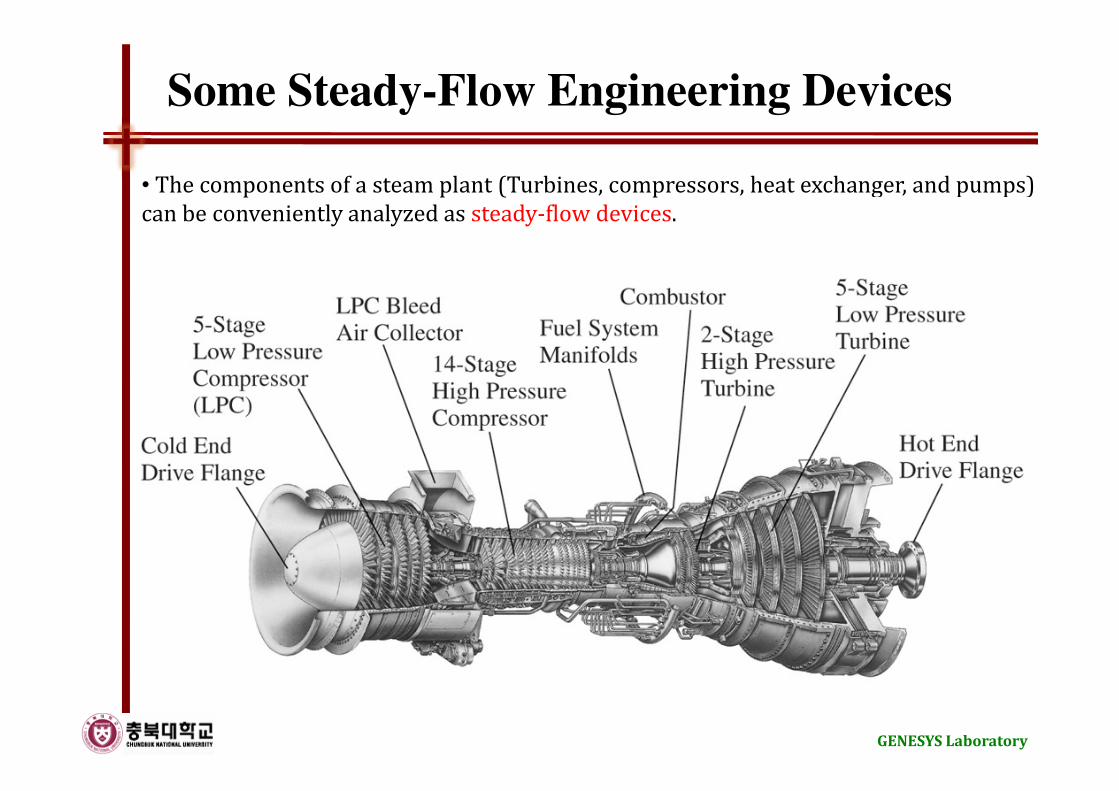
Some Steady-Flow Engineering Devices
• The components of a steam plant (Turbines, compressors, heat exchanger, and pumps)
can be conveniently analyzed as steady-flow devices.
GENESYS Laboratory
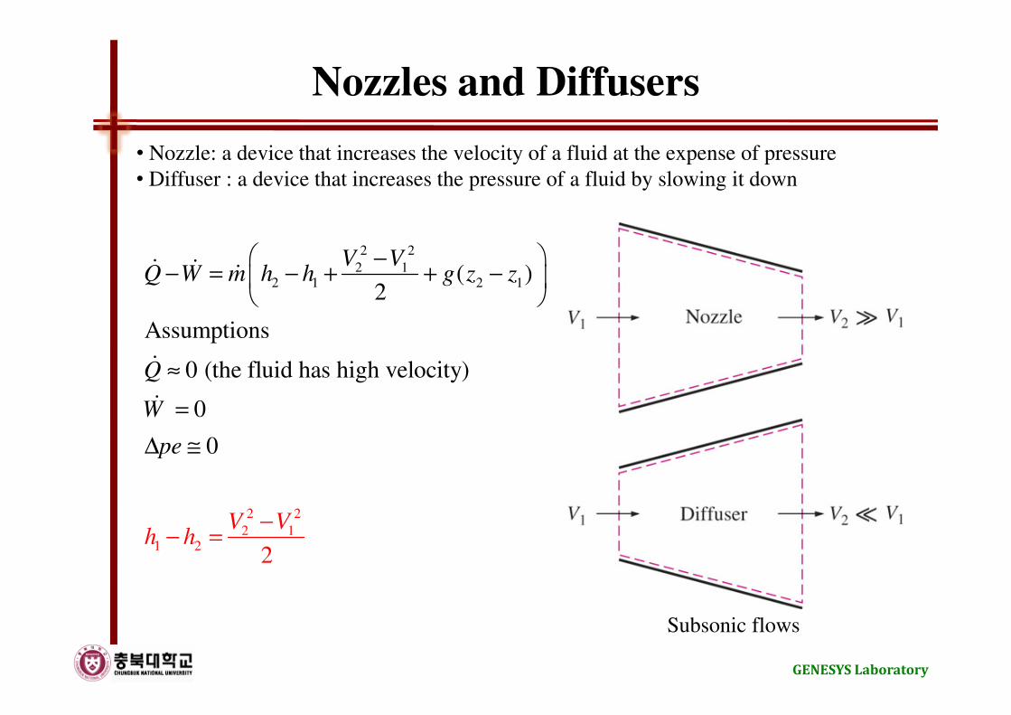
Nozzles and Diffusers
• Nozzle: a device that increases the velocity of a fluid at the expense of pressure
• Diffuser : a device that increases the pressure of a fluid by slowing it down
2 2
2 12 1 2 1
2 2
2 11 2
( )2
Assumptions
0 (the fluid has high velocity)
0
0
2
V VQ W m h
V Vh h
h g z z
Q
W
pe
−− = − + +
−− =
−
≈
=
∆ ≅
ɺ ɺ ɺ
ɺ
ɺ
Subsonic flows
GENESYS Laboratory
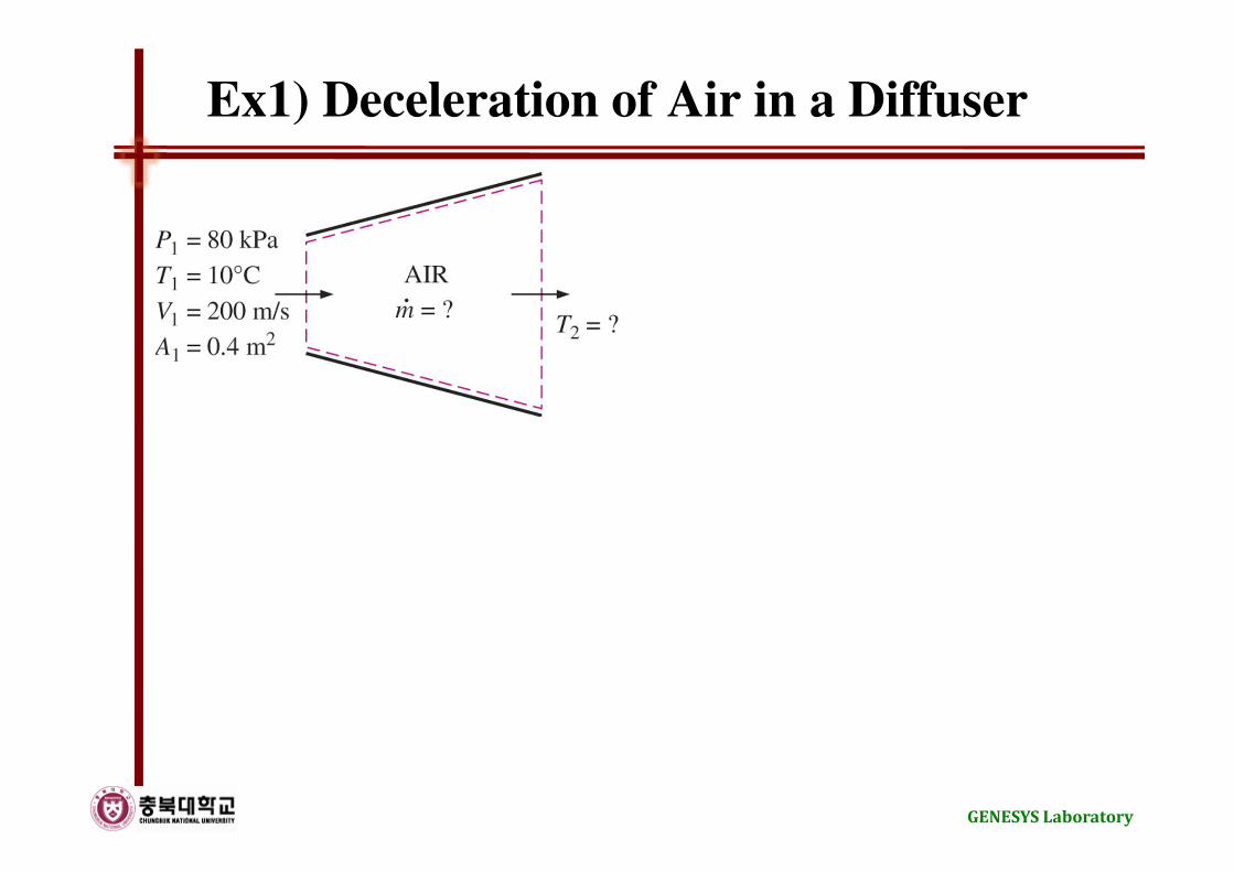
Ex1) Deceleration of Air in a Diffuser
GENESYS Laboratory
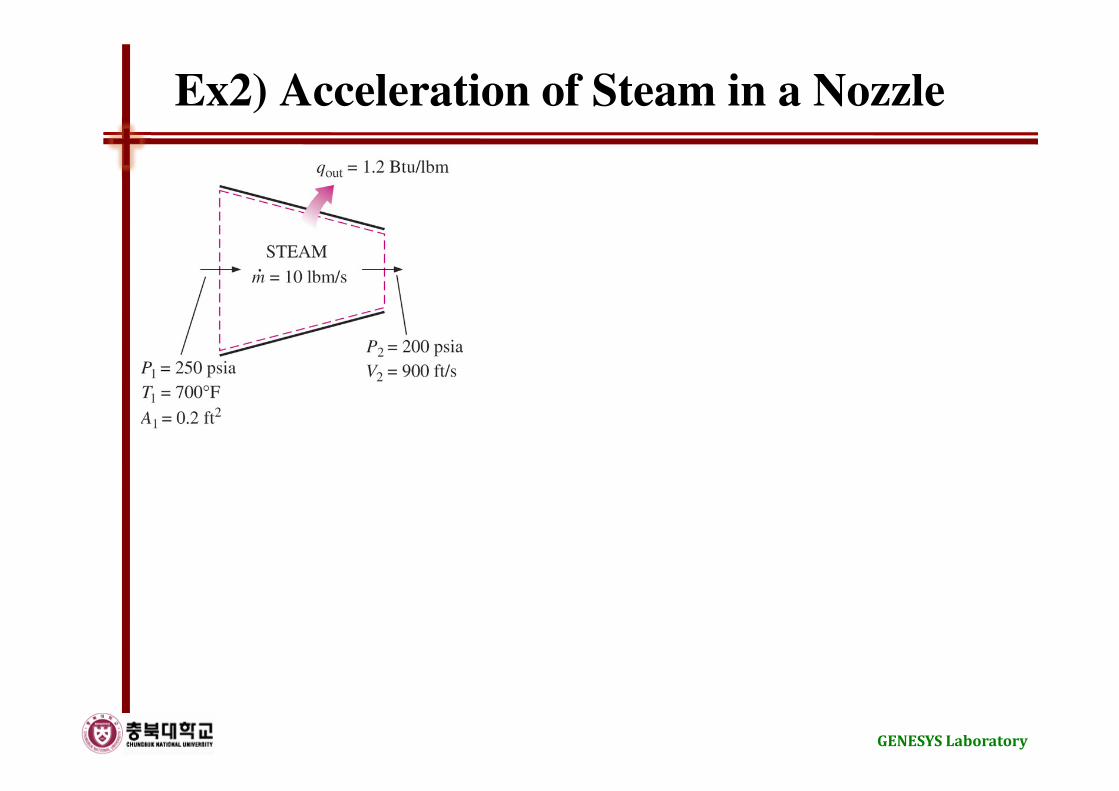
Ex2) Acceleration of Steam in a Nozzle
GENESYS Laboratory
Turbines and Compressors
• Turbine: a device that drives the electric generator
• Compressor: a device that increases the pressure of a fluid
( )
2 2
2 12 1 2 1
1 2
( )2
Assumptions
0 (well insulated)
0
0
V VQ W m h h g z z
Q
pe
ke ke h
W m h h
−− = − + + −
≈
∆ ≅
∆ ≅ ← ∆ ⟨⟨∆
= −
ɺ ɺ ɺ
ɺ
ɺ ɺ
GENESYS Laboratory
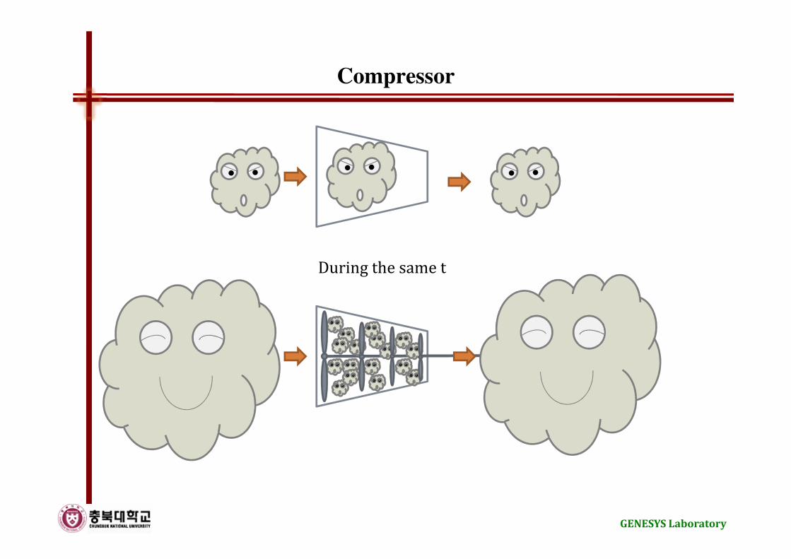
Compressor
During the same t
GENESYS Laboratory
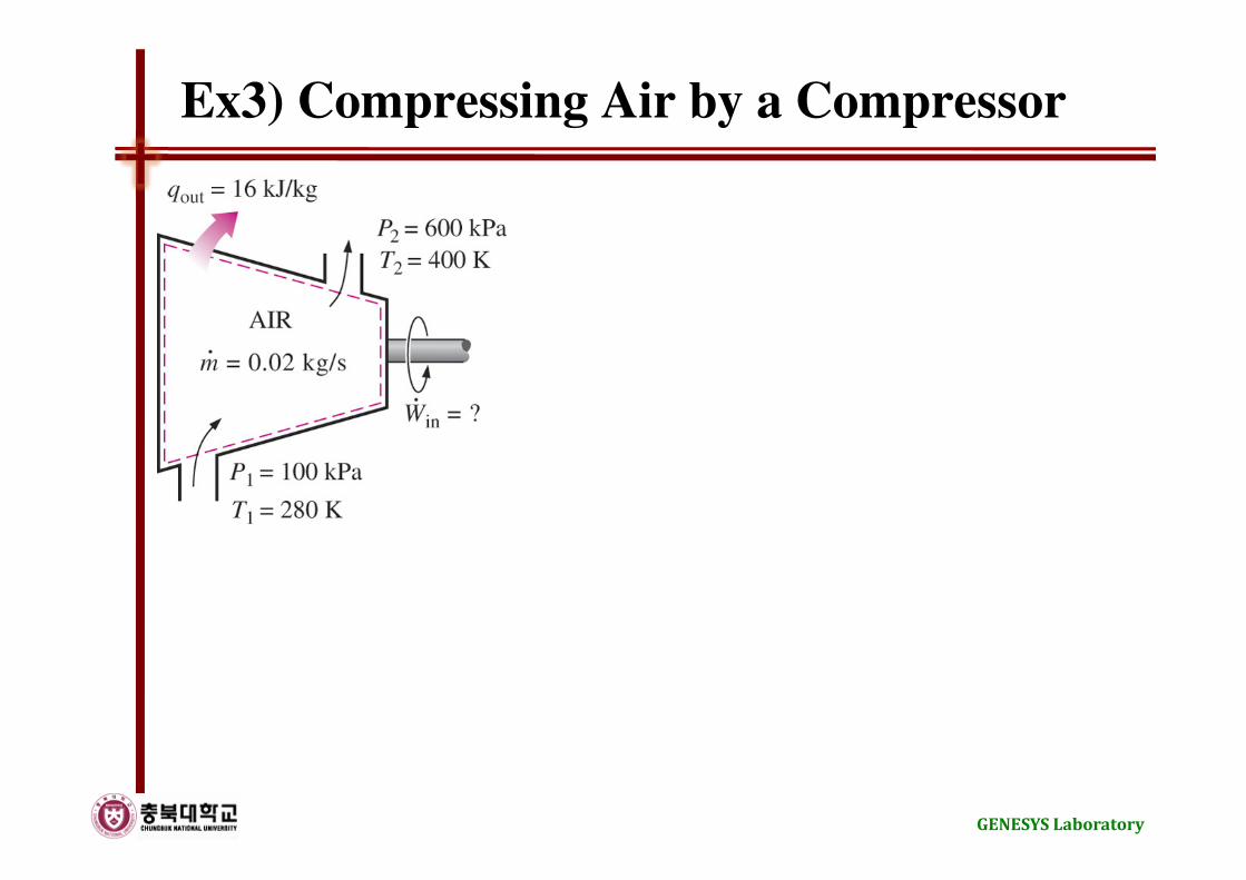
Ex3) Compressing Air by a Compressor
GENESYS Laboratory
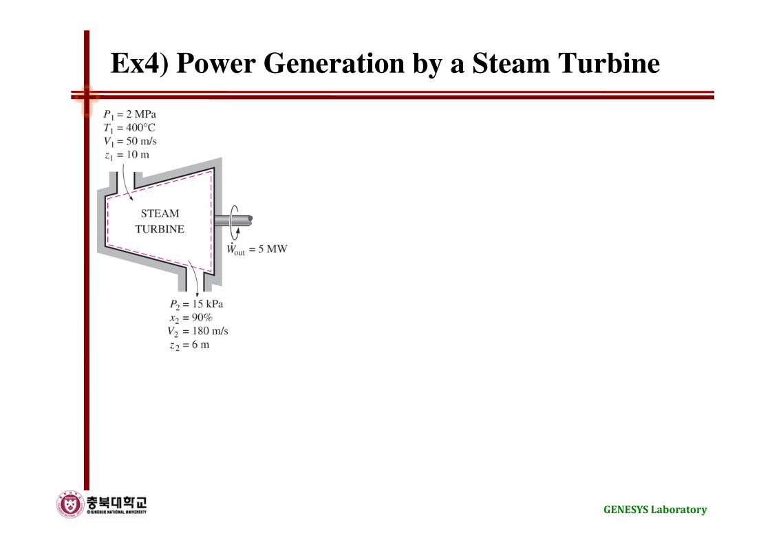
Ex4) Power Generation by a Steam Turbine
GENESYS Laboratory

Throttling Valves
• Throttling valve: a device that cause large pressure drops in the fluid
2 2
2 12 1 2 1
2 1
1 1 1 2 2 2
( )2
Assumptions
0 (well insulated)
0
0
0
isenthalpic device or constant enthalpy device
V VQ W m h h g z z
Q
W
pe
ke ke h
h h
u Pv u P v
−− = − + + −
≈
≈
∆ ≅
∆ ≅ ← ∆ ⟨⟨∆
≅ ←
⇒ + = +
ɺ ɺ ɺ
ɺ
ɺ
GENESYS Laboratory
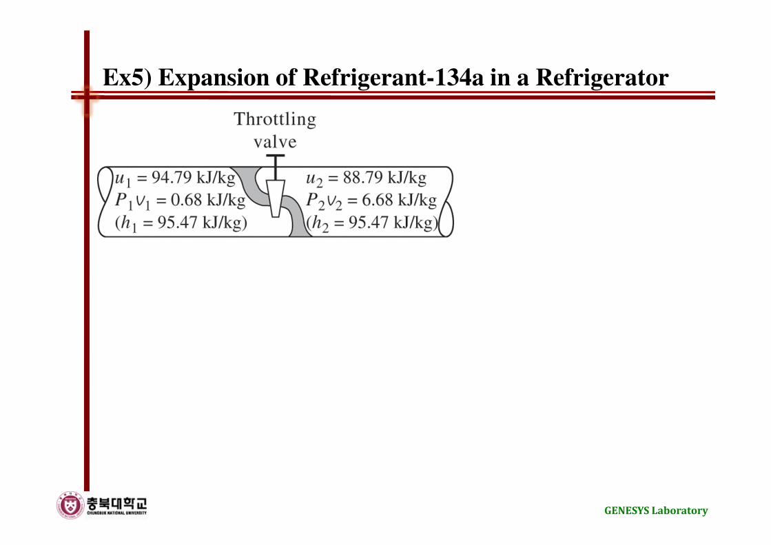
Ex5) Expansion of Refrigerant-134a in a Refrigerator
GENESYS Laboratory

Mixing Chambers
• Mixing chamber: a section where the mixing process takes place
( )
2 2
2 12 1 2 1
1 2
( )2
Assumptions
0 (well insulated)
0
0
0
0
V VQ W m h h g z z
Q
W
pe
ke
m h h
−− = − + + −
≈
=
∆ ≅
∆ ≅
− =
ɺ ɺ ɺ
ɺ
ɺ
ɺ
GENESYS Laboratory
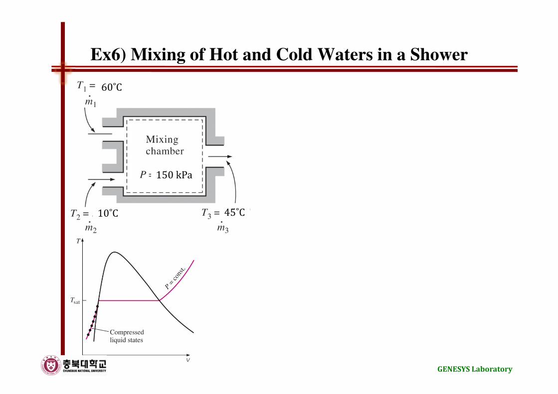
Ex6) Mixing of Hot and Cold Waters in a Shower
60˚C
10˚C 45˚C
150 kPa
GENESYS Laboratory
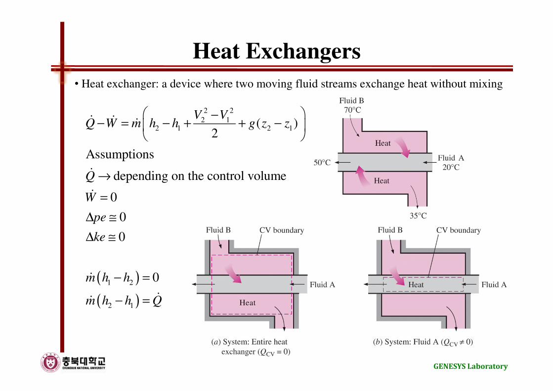
Heat Exchangers
• Heat exchanger: a device where two moving fluid streams exchange heat without mixing
( )
( )
2 2
2 12 1 2 1
1 2
2 1
( )2
Assumptions
depending on the control volume
0
0
0
0
V VQ W m h h g z z
Q
W
pe
ke
m h h
m h h Q
−− = − + + −
→
=
∆ ≅
∆ ≅
− =
− =
ɺ ɺ ɺ
ɺ
ɺ
ɺ
ɺɺ
GENESYS Laboratory
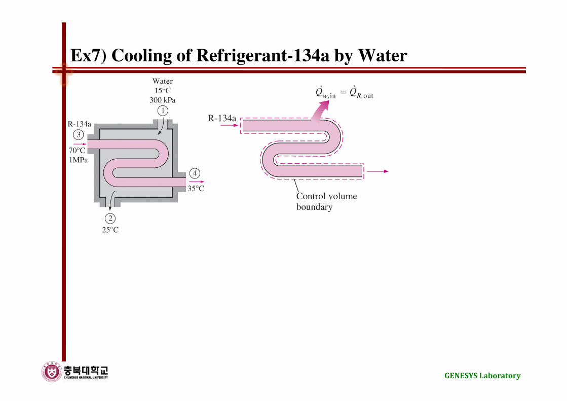
Ex7) Cooling of Refrigerant-134a by Water
GENESYS Laboratory

Pipe and Duct Flow
( )
( ) ( )
2 2
2 12 1 2 1
cv cv 2 1
2 1 2 1 2 1
( )2
Assumptions
depending on the control volume
depending on the control volume
0
0
at incompressible substance
(
V VQ W m h h g z z
Q
W
pe
ke
Q W m h h
∆h h h u u v P P
c
−− = − + + −
→
→
∆ ≅
∆ ≅
− = −
= − = − + −
=
ɺ ɺ ɺ
ɺ
ɺ
ɺ ɺ ɺ
( )2 1 2 1)T T v P P− + −
GENESYS Laboratory
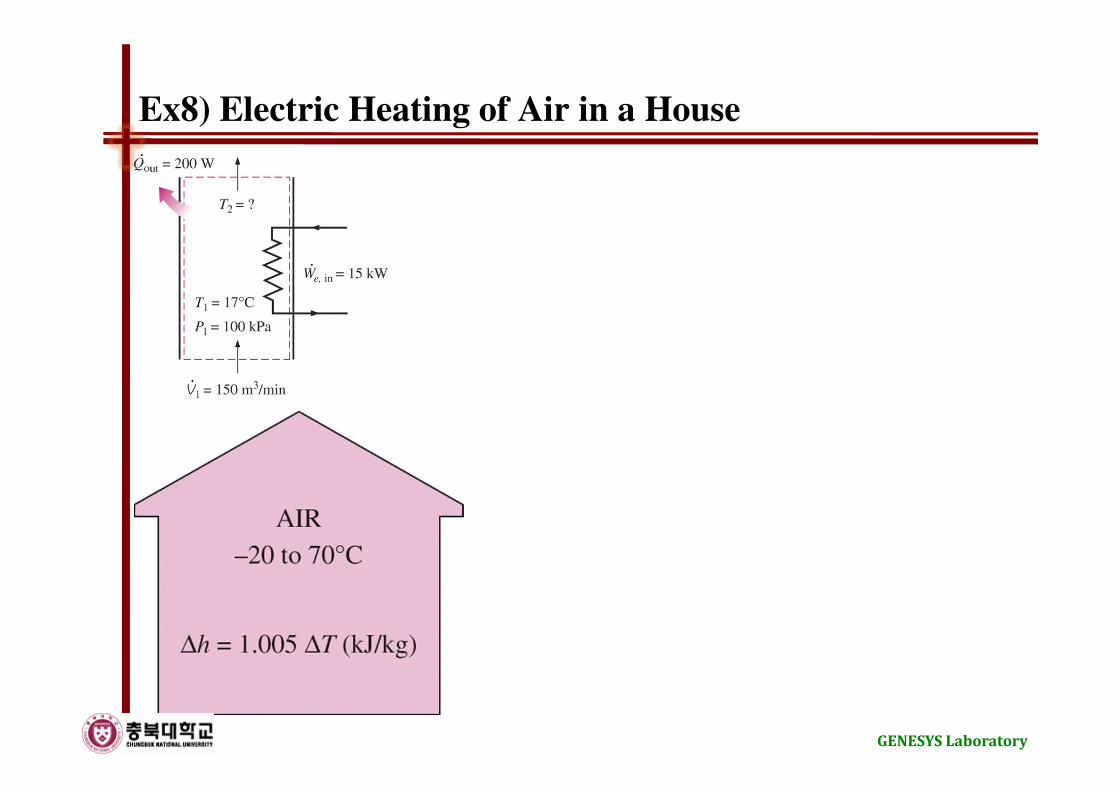
Ex8) Electric Heating of Air in a House
GENESYS Laboratory
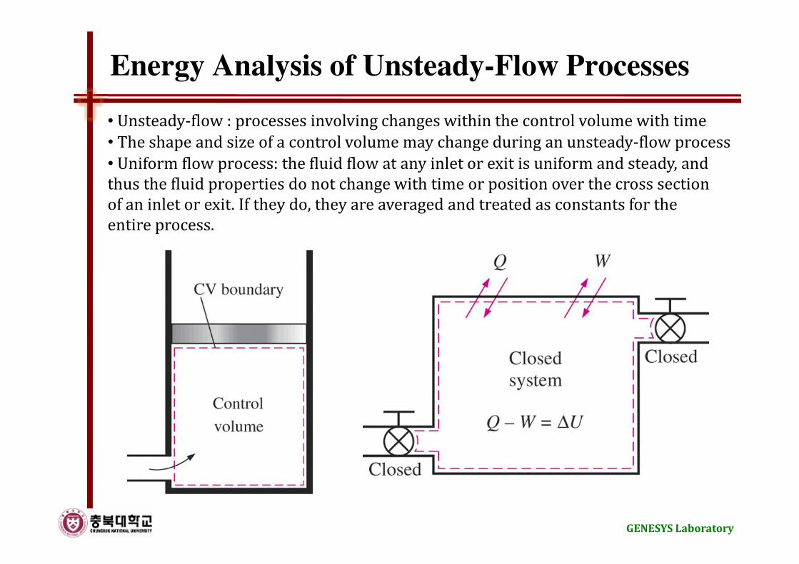
Energy Analysis of Unsteady-Flow Processes
• Unsteady-flow : processes involving changes within the control volume with time
• Uniform flow process: the fluid flow at any inlet or exit is uniform and steady, and
thus the fluid properties do not change with time or position over the cross section
of an inlet or exit. If they do, they are averaged and treated as constants for the
entire process.
• The shape and size of a control volume may change during an unsteady-flow process
GENESYS Laboratory
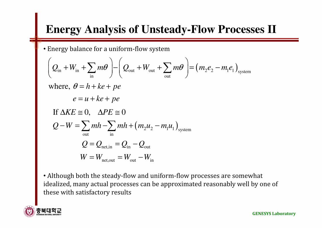
Energy Analysis of Unsteady-Flow Processes II
• Energy balance for a uniform-flow system
( )in in out out 2 2 1 1 systemin out
where,
Q W m Q W m m e m e
h ke pe
e u ke pe
θ θ
θ
+ + − + + = −
= + +
= + +
∑ ∑
( )2 2 1 1 systemout in
net,in in out
net,out out in
If 0, 0
KE PE
Q W mh mh m u m u
Q Q Q Q
W W W W
∆ ≅ ∆ ≅
− = − + −
= = −
= = −
∑ ∑
• Although both the steady-flow and uniform-flow processes are somewhat
idealized, many actual processes can be approximated reasonably well by one of
these with satisfactory results
GENESYS Laboratory
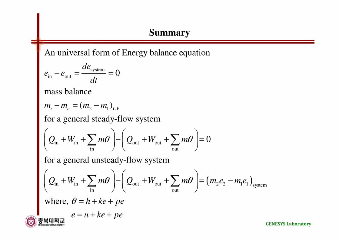
Summary
system
in out
2 1
in in out out
in out
An universal form of Energy balance equation
0
mass balance
( )
for a general steady-flow system
0
for a general unsteady-flow syst
i e CV
dee e
dt
m m m m
Q W m Q W mθ θ
− = =
− = −
+ + − + + =
∑ ∑
( )in in out out 2 2 1 1 systemin out
em
where,
Q W m Q W m m e m e
h ke pe
e u ke pe
θ θ
θ
+ + − + + = −
= + +
= + +
∑ ∑
GENESYS Laboratory
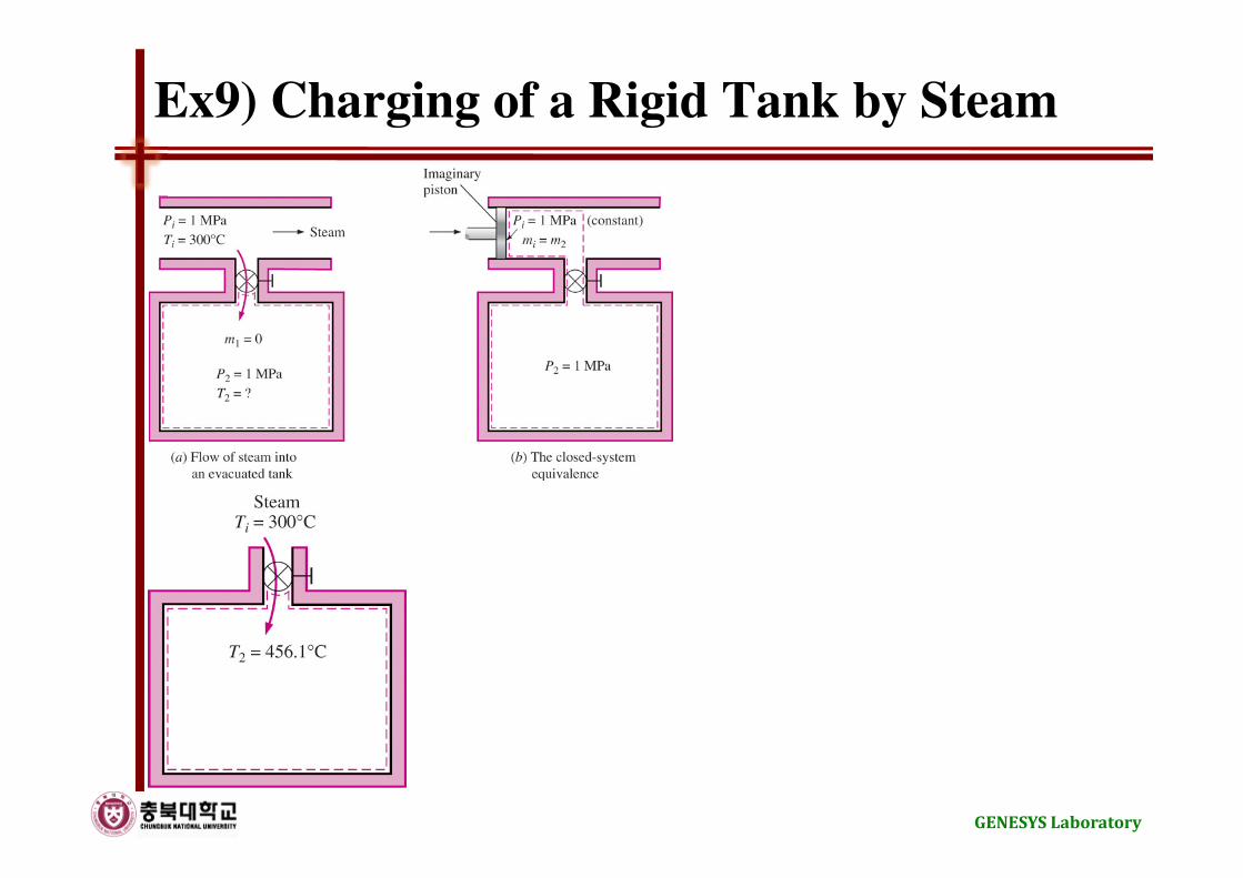
Ex9) Charging of a Rigid Tank by Steam
GENESYS Laboratory

Ex10) Cooking with a Pressure Cooker
GENESYS Laboratory