week 7 chapter 4 shear forces and bending momentsocw.snu.ac.kr/sites/default/files/note/9432.pdf ·...
TRANSCRIPT

Week 6 & 7, 5 & 12 March
Mechanics in Energy Resources Engineering- Chapter 4 Shear Forces and Bending Moments
Ki B k Mi PhDKi-Bok Min, PhD
Assistant ProfessorE R E i iEnergy Resources EngineeringSeoul National University

1st exam
• Mean: 65.3, standard deviation: 12.9• Max: 86 0 Min: 30 0• Max: 86.0, Min: 30.0
30 ~ 40 2 students30 40, 2 students
50 ~ 60: 4 students60 ~ 70, 9 students,
80 ~ 90: 2 students70 ~ 80, 8 students

1st Exam
• In general, you demonstrated your understanding to a reasonable extent and you are in good positions to study further.
• Try to thoroughly understand the home assignments. I Try to thoroughly understand the home assignments. I encourage discussion with your peers.Thi ti l ti l i t d 10% 70% H • This time only, partial point was around 10% - 70%. However, it will be minimized next time. Max partial point will be 30%.
• Level of difficulty will be similar in the 2nd and 3rd exam.• 2nd exam: Ch 4 5 & 12• 2nd exam: Ch. 4, 5 & 12• 3rd exam: entire chapters.

Review
• Introduction
• Torsional Deformations of a circular bar (원형봉의비틀림변형)
• Circular bars of linearly elastic materials (선형탄성원형봉)
• Nonuniform torsion (불균질비틀림)
• Stresses and Strains in Pure Shear (순수전단에서의응력과변형율)
• Relationship Between Moduli of Elasticity E and G (탄성계수 E와 G의관계)
• Statically Indeterminate Torsional Members (부정정비틀림부재)
• Strain Energy in Torsion and Pure Shear (비틀림과순수전단에서의변형에너지)변형에너지)

Change of schedule
– 5 April (Ch.4) 7 April (Ch.12) by Jae-Won Lee– 12 April (Ch.4) 14 April (Ch.5), hw#4 duep ( ) p ( )– 19 April (Ch.5), hw#5 due 21 April (Ch.5)
26 April (Review) 28 April (2nd Exam) hw#6 due– 26 April (Review), 28 April (2nd Exam), hw#6 due

Shear Forces and Bending MomentsP iPreview
• Introduction• Types of Beams Loads and Reactions• Types of Beams, Loads, and Reactions• Shear Forces and Bending Moments• Relationships Between Loads, Shear Forces and Bending
MomentsMoments• Shear-Force and Bending-Moment Diagrams

Introduction
• Structural members (구조용부재)– Axially loaded bar (봉): forces along the axisAxially loaded bar (봉): forces along the axis– A bar in torsion: torques along the axis (moment vectors)
B (보) l t l l d– Beam (보): lateral loads
• Planar structure (평면구조물) lie in a single plane( ) g p– Loads and deflections occurs in the plane of bending

Types of Beams, Loads, and Reactionsbbeams
• Assumptions– Loads act in the plane of the figure: force vectors in the plane of Loads act in the plane of the figure: force vectors in the plane of
figure & bending moments have their moments vectors perpendicular to the plane of the figure
– Beam is symmetric about that plane deflect only in the plane of bending

Types of Beams, Loads, and ReactionsT f BTypes of Beams
• Simple beam (단순보)
• Cantilever beam (캔틸레버보)
• Beam with an overhang (돌출보)

Types of Beams, Loads, and Reactions T f tTypes of supports
Free body Diagram
Free body Diagram
Free body DiagramDiagram

Types of Beams, Loads, and ReactionsA t l E lActual Examples

Types of Beams, Loads, and ReactionsL dLoads
• Concentrated load– applied over a very small areaapplied over a very small area
• Distributed load– Spread along the axis of a beam– Measured by their intensity (Force/unit distance)y y ( )– Uniformly distributed & linearly varying load
C l• Couple– The couple of moment M1 (bending moment) 1
acting on the overhang

Types of Beams, Loads, and ReactionsR tiReactions
• Simple beam

Types of Beams, Loads, and ReactionsR tiReactions
• Cantilever beam

Types of Beams, Loads, and ReactionsR tiReactions
• Beam with an overhang

Shear Forces and Bending Momentsb i t basic concepts
• Beams under forces or moment stresses and strains are created throughout the interior of the beam.
• We first find the internal forces and couple We first find the internal forces and couple (bending moment) on the cross section.
Stress resultant (합응력): resultants of – Stress resultant (합응력): resultants of stresses distributed over the cross section.
F B d Di i l t l ft i ht • Free Body Diagram – isolate left or right hand part.

Shear Forces and Bending Momentsth d lmethodology
• Equilibrium Equation
0 0verF 0P V
V PV P
0M 0M Px 0M Px
M Px

Shear Forces and Bending Momentsi ti f t lt tsign conventions for stress resultants
• ‘deformation sign convention’– Based on how the material is deformed.Based on how the material is deformed.– (+) shear force: acts clockwise
( ) h f t l k i– (-) shear force: ….. counter-clockwise– (+) bending moment: compress upper part– (-) bending moment: ……….. lower part
• ‘ static sign convention’• static sign convention– Forces/moments are (+) or (-) according to
th i di titheir directions– Sign convention for Equilibrium Equation.

Summary
• Introduction• Types of Beams Loads and Reactions• Types of Beams, Loads, and Reactions• Shear Forces and Bending Moments
• Relationships Between Loads, Shear Forces and Bending p , gMoments
• Shear Force and Bending Moment Diagrams• Shear-Force and Bending-Moment DiagramsNext Monday

Shear Forces and Bending MomentsE l 4 1Example 4-1
• Shear force V & bending moment M at the right and left of mid point?
– RA & RB?– Free Body Diagram– Free Body Diagram.
0AM 0
4BMPRL
4 L
0BM 034A
MR PL

Shear Forces and Bending MomentsE l 4 1Example 4-1
• To the left0VF
0
4MPVL
0VF0
8 2MPLM 0AM
4 L
T th i ht
8 2
• To the right
0F 0
4MPVL
No change in shear force0VF
0
8 2MPLM 0cutM
4 L
Increase by M08 2

Shear Forces and Bending MomentsE l 4 2Example 4-2
• Shear force V & Bending moment M?– Intensity of the distributed load at xIntensity of the distributed load at x
Sh F
0qq xL
2– Shear Force 20
2q xV
L 0
max 2q LV
– Bending moment0M 01 ( ) 0q x xM x
30q xM dV dM
0M ( ) 02 3
M xL
20q LM
6M
L dV q
dx
dM Vdx
max 6
M

Shear Forces and Bending MomentsE l 4 3Example 4-3
• Shear force V & bending moment M at D?
Relationships Between Loads, Shear F d B di M tForces and Bending Moments
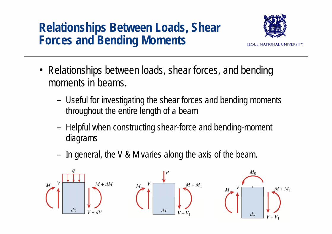
• Relationships between loads, shear forces, and bending moments in beams.
– Useful for investigating the shear forces and bending moments throughout the entire length of a beam
– Helpful when constructing shear-force and bending-moment diagrams
– In general, the V & M varies along the axis of the beam.
Relationships Between Loads, Shear Forces and Bending MomentsBending Momentssign convention
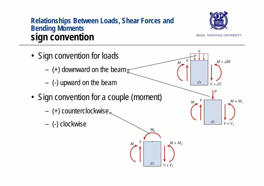
• Sign convention for loads– (+) downward on the beam( ) downward on the beam– (-) upward on the beam
• Sign convention for a couple (moment)– (+) counterclockwise( )– (-) clockwise

Relationships Between Loads, Shear Forces and Bending MomentsBending MomentsDistributed Loads
• From Equilibrium of forces0VF ( ) 0V qdx V dV 0VF ( ) 0V qdx V dV
dV qdx
– Rate of change of the shear force at any point on the axis of the beam = negative of the intensity of the distributed load
dx
– (-) sign change to (+) for positive upward distributed load– If q = 0 dV/dx = 0 and V is constant in that part of the beam– If q = 0, dV/dx = 0 and V is constant in that part of the beam– If q = constant, dV/dx is also constant and V varies linearly in that
part of the beampart of the beam

Relationships Between Loads, Shear Forces and Bending MomentsBending MomentsDistributed Loads
dV qdx
• Integrate above equation after multiplying with dxB BB B
A AdV qdx
( )B
V V qdx area of the loading diagram between A and B ( )B A AV V qdx area of the loading diagram between A and B
Change in shear force between two points along
Negative of the total downward load between =
the axis of the beam those points

Relationships Between Loads, Shear Forces and Bending MomentsBending MomentsDistributed Loads
• From Moment Equilibrium0l ftM ( ) 0dxM qdx V dV dx M dM 0leftM ( ) 0
2M qdx V dV dx M dM
dM Vdx
– Rate of change of the bending moment at any point on the axis of the beam = shear force at that same point
dx
B B
A AdM Vdx
( )B
d f h h f d b d ( )B A AM M Vdx area of the shear force diagram between A and B

Relationships Between Loads, Shear Forces and Bending MomentsBending MomentsConcentrated Loads
• From Force Equilibrium,0VF ( ) 0V P V V 1V P
– Shear force decreases by P
0VF 1( ) 0V P V V 1V P
• From Moment Equilibrium,0leftM
1 1( ) 0dxM P V V dx M M 1 1( )2
1 12dxM P Vdx Vdx
• dx is infinitesimally small M1 is also very small
• Bending moment does notchange as we pass through the point of application of a concentrated load

Relationships Between Loads, Shear Forces and Bending MomentsBending MomentsLoads in the form of couples
• From Force Equilibrium,1 0V
– Shear force does not change at the point of application of a couple
1 0V
• From Moment Equilibrium,
0M ( ) 0M M V V d M M0leftM 0 1 1( ) 0M M V V dx M M
1 0M M
• Bending moment decreases by M0 as we move from left to right through the point of load application bending moment right through the point of load application bending moment change abruptly.

Shear-Force and Bending-Moment DiDiagrams
• Graph in which shear force and bending moment are plotted with respect to distance x along the axis of the beam.
• How shear forces and bending moments vary throughout the length of the beam? Maximum?length of the beam? Maximum?
• Shear Force Diagram (SFD, 전단력선도)• Bending Moment Diagram (BMD, 굽힘모멘트선도)

Shear-Force and Bending-Moment DiagramsConcentrated LoadConcentrated Load
• Determine Reactions from moment equilibrium,A
PbRL
BPaRL
• V & M at the left part (0 < x < a),
A L B L
Pb Pb
V & M t th i ht t ( L)
APbV RL
APbxM R xL
• V & M at the right part (a < x < L),Pb PaV R P P AV R P PL L
( ) ( ) ( )APbx PaM R x P x a P x a L xL L
L L

Shear-Force and Bending-Moment DiagramsConcentrated LoadConcentrated Load
• Shear Force Diagram,(0 )PbV x a (0 )V x a
L
(0 )PaV x a
B di M t Di
(0 )V x aL
Slope dV/dx =0 q=0Area for x < a
• Bending Moment Diagram
( )PbxM a x L
increase in MArea for a<x<b decrease in M( )M a x L
L
( ) ( )PaM L L
decrease in M
( ) ( )M L x a x LL
Slope dM/dx = V

Shear-Force and Bending-Moment DiagramsUniform LoadUniform Load
• From Moment Equilibrium,qLR R
• From Free Body Diagram,2A BR R
2AqLV R qx qx
2
2 2 2Ax qLx qxM R x qx
• Slope of V?• Slope of M?

Shear-Force and Bending-Moment DiagramsSeveral Concentrated LoadsSeveral Concentrated Loads
• From Moment Equilibrium,R R P P P
• From Free Body Diagram,1 2 3A BR R P P P
1(0 )A AV R M R x x a
1 1 1 1 2( ) ( )A AV R P M R x P x a a x a 1 1 1 1 2( ) ( )A AV R P M R x P x a a x a
3BV R P 3
3 3 2 3( ) ( ) ( )BM R L x P L b x a x a
V R
3( ) ( )B
B
V RM R L x a x L

Shear-Force and Bending-Moment DiagramsSeveral Concentrated LoadsSeveral Concentrated Loads
• Bending moment,1 1AM R a1 1
2 2 1 2 1
3 3
( )A
A
B
M R a P a aM R b
• Maximum positive momentM i ti t
3 3B
• Maximum negative moment numerically largest negative moment

Shear-Force and Bending-Moment DiagramsSeveral Concentrated LoadsSeveral Concentrated Loads
• Maximum positive and negative bending moments– A cross section where a concentrated load is applied and shear A cross section where a concentrated load is applied and shear
force changes sign– A cross section where the shear force =0A cross section where the shear force 0– A point of support where a vertical reaction is present– A cross section where a couple is applied

Summary
• Introduction• Types of Beams Loads and Reactions• Types of Beams, Loads, and Reactions• Shear Forces and Bending Moments• Relationships Between Loads, Shear Forces and Bending
MomentsMoments• Shear-Force and Bending-Moment Diagrams

Next three lectures
• Introduction• Pure Bending and Nonuniform Bendingg g• Curvature of Beam
Longitudinal Strains in Beams• Longitudinal Strains in Beams• Normal Stress in Beams• Design of Beams for Bending Stresses• Nonprismatic BeamsNonprismatic Beams• Shear Stresses in Beams of Rectangular Cross Section• Shear Stresses in Beams of Circular Cross Section• Shear Stresses in the Webs of Beams with Flanges