week 6: processor components -...
TRANSCRIPT
Week 6: Processor Components
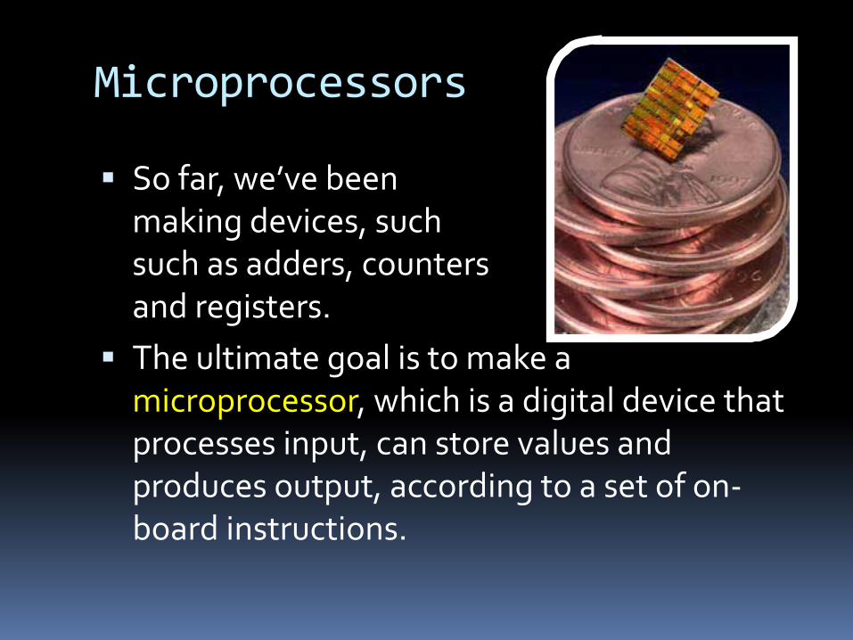
Microprocessors
§ So far, we’ve been about making devices, suchsuch as adders, countersand registers.
§ The ultimate goal is to make a microprocessor, which is a digital device that processes input, can store values and produces output, according to a set of on-board instructions.
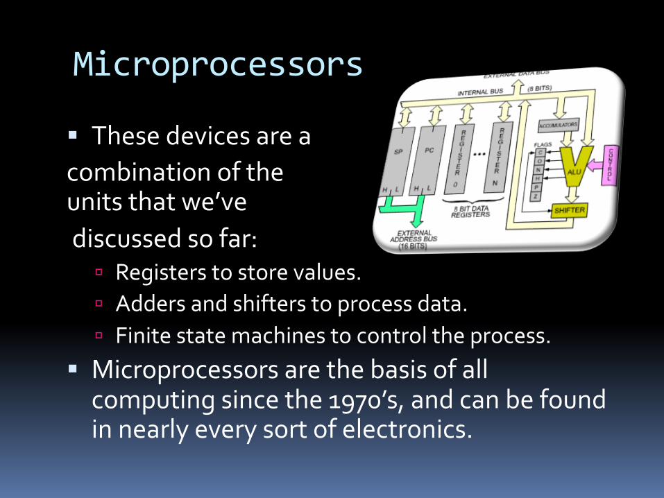
Microprocessors
§ These devices are a combination of theunits that we’vediscussed so far:
ú Registers to store values.ú Adders and shifters to process data.ú Finite state machines to control the process.
§ Microprocessors are the basis of all computing since the 1970’s, and can be found in nearly every sort of electronics.

We built these
ProcessorsFinite State Machines
Arithmetic Logic Units
Devices Flip-flops
Circuits
Logic Gates
Transistors
Assembly Language
To get to this

Read reg 1
Read reg 2
Write reg
Write data
Read data 1
Read data 2
Registers
ALU result
ZeroA
BALU
0
1
0123
4
A
B
Instruction [31-26]
Instruction Register
Instruction [25-21]
Instruction [20-16]
Instruction [15-0] 0
1
0
1Memory data
register
Memory data
Memory
Address
Write data
ALU Out
012Shift left 2
0
1
PC
PCWriteCond
PCWriteIorD
MemReadMemWriteMemtoRegIRWrite
PCSourceALUOp
ALUSrcBALUSrcARegWriteRegDst
Opcode
ControlUnit
Shift left 2Sign extend
The Final Destination
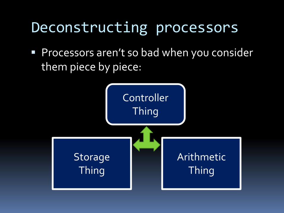
Deconstructing processors§ Processors aren’t so bad when you consider
them piece by piece:
Storage Thing
Arithmetic Thing
Controller Thing

aka: the Arithmetic Logic Unit (ALU)
The “Arithmetic Thing”
Arithmetic Logic Unit
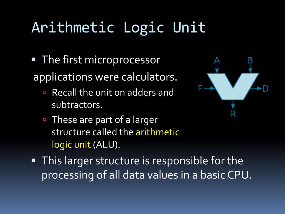
§ The first microprocessorapplications were calculators.
ú Recall the unit on adders and subtractors.
ú These are part of a larger structure called the arithmetic logic unit (ALU).
§ This larger structure is responsible for the processing of all data values in a basic CPU.
ALU inputs
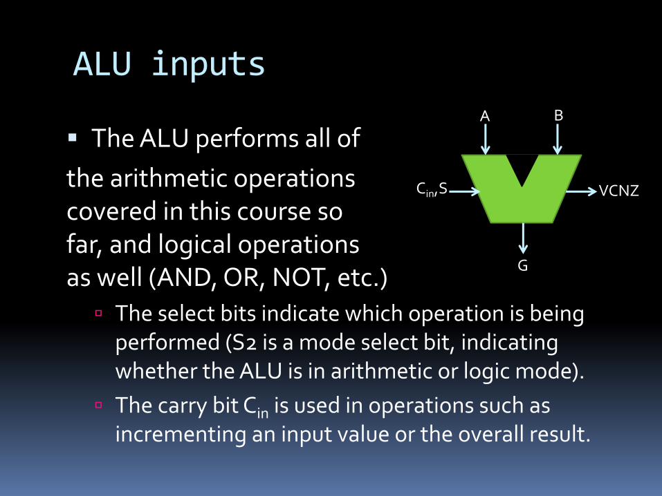
§ The ALU performs all of the arithmetic operationscovered in this course sofar, and logical operationsas well (AND, OR, NOT, etc.)
ú The select bits indicate which operation is being performed (S2 is a mode select bit, indicating whether the ALU is in arithmetic or logic mode).
ú The carry bit Cin is used in operations such as incrementing an input value or the overall result.
A B
G
Cin,S VCNZ

ALU outputs
§ In addition to the inputsignals, there are outputsignals V, C, N & Z whichindicate special conditionsin the arithmetic result:ú V: overflow condition
The result of the operation could not be stored in the n bits of G, meaning that the result is incorrect.
ú C: carry-out bitú N: Negative indicatorú Z: Zero-condition indicator
A B
G
Cin,S VCNZ

The “A” of ALU§ To understand how the ALU does all of these
operations, let’s start with the arithmetic side.§ Fundamentally, this side is made of an adder /
subtractor unit, which we’ve seen already:
CinFA
X0
Y0
S0
FA
X1
Y1
S1
C1FA
X2
Y2
S2
C2FA
X3
Y3
S3
C3Cout
Sub

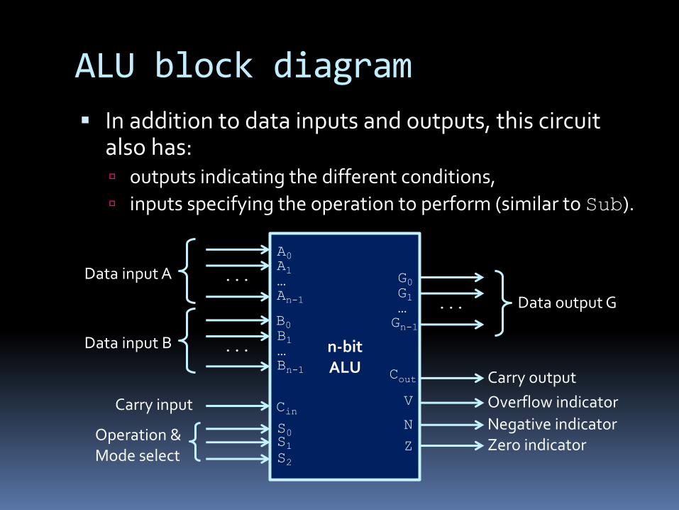
ALU block diagram§ In addition to data inputs and outputs, this circuit
also has: ú outputs indicating the different conditions,ú inputs specifying the operation to perform (similar to Sub).
n-bit ALU
A0A1…An-1B0B1…Bn-1
...
...
G0G1…Gn-1
...
Data input A
Data input B
Data output G
CinS0
S2S1
Carry input
Operation &Mode select
Cout Carry outputOverflow indicatorNegative indicatorZero indicator
V
NZ
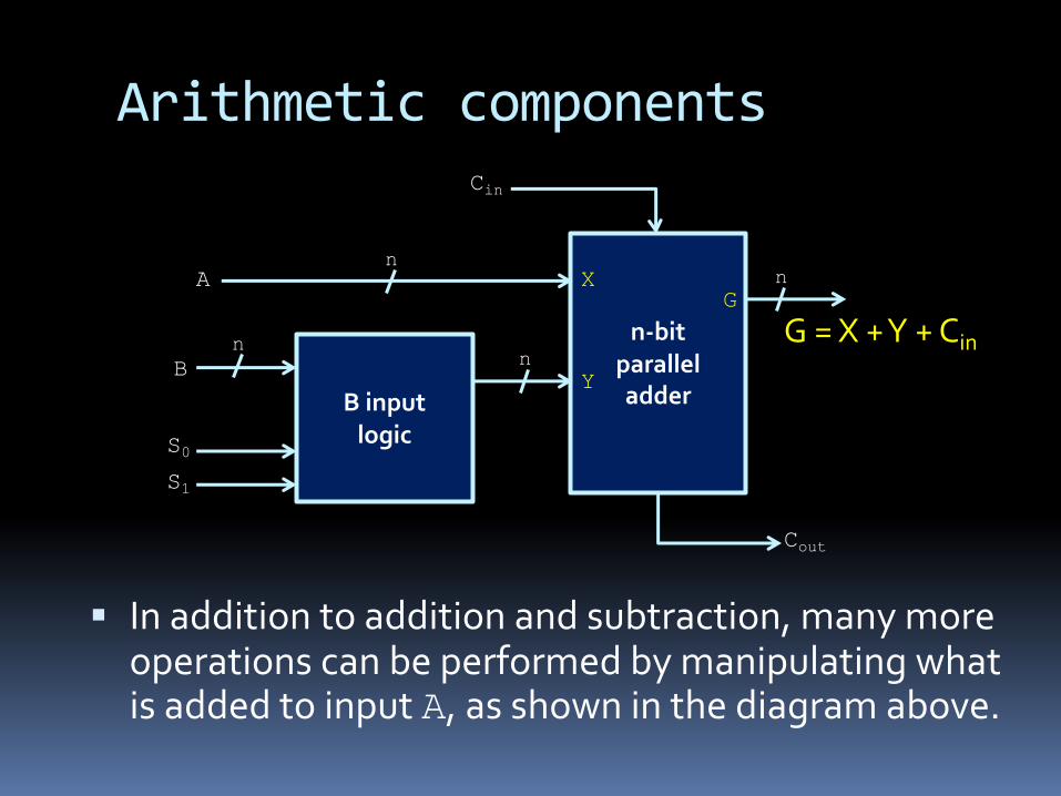
Arithmetic components
§ In addition to addition and subtraction, many more operations can be performed by manipulating what is added to input A, as shown in the diagram above.
B inputlogic
n-bit paralleladder
A
B
Cin
S0S1
GG = X + Y + Cin
Cout
X
Y
n
nn
n
Arithmetic operations
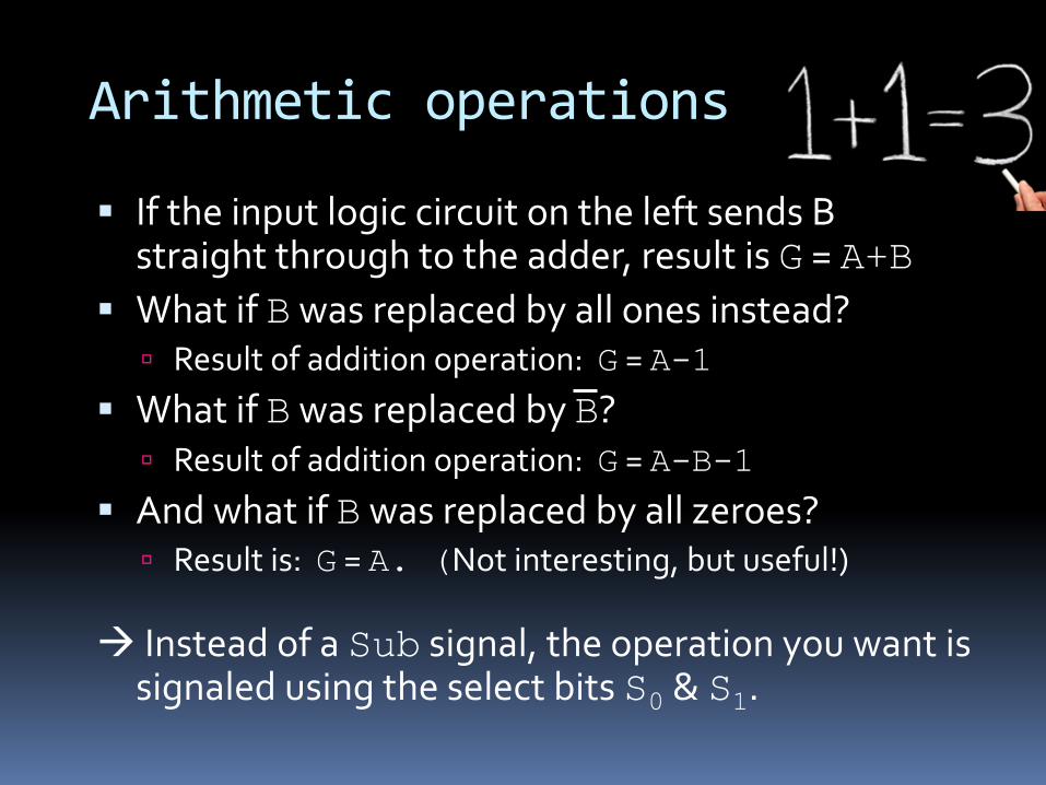
§ If the input logic circuit on the left sends B straight through to the adder, result is G = A+B
§ What if Bwas replaced by all ones instead?ú Result of addition operation: G = A-1
§ What if Bwas replaced by B?ú Result of addition operation: G = A-B-1
§ And what if Bwas replaced by all zeroes?ú Result is: G = A. (Not interesting, but useful!)
à Instead of a Sub signal, the operation you want is signaled using the select bits S0 & S1.
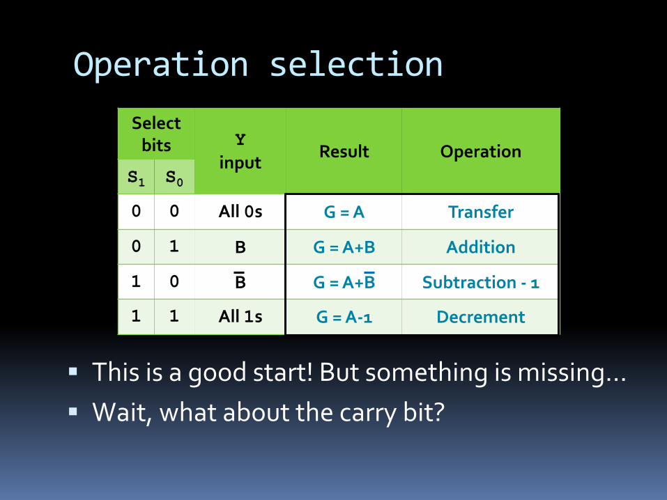
Operation selection
§ This is a good start! But something is missing…§ Wait, what about the carry bit?
Select bits Y
inputResult Operation
S1 S00 0 All 0s G = A Transfer
0 1 B G = A+B Addition
1 0 B G = A+B Subtraction - 1
1 1 All 1s G = A-1 Decrement
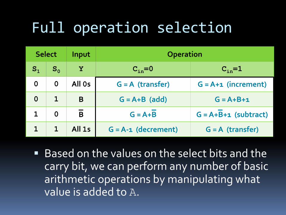
Full operation selection
§ Based on the values on the select bits and the carry bit, we can perform any number of basic arithmetic operations by manipulating what value is added to A.
Select Input Operation
S1 S0 Y Cin=0 Cin=1
0 0 All 0s G = A (transfer) G = A+1 (increment)
0 1 B G = A+B (add) G = A+B+1
1 0 B G = A+B G = A+B+1 (subtract)
1 1 All 1s G = A-1 (decrement) G = A (transfer)

The “L” of ALU§ We also want a circuit
that can performlogical operations,in addition toarithmetic ones.
§ How do we tellwhich operationto perform?ú Another select bit!
§ If S2 = 1, then logic circuit block is activated.§ Multiplexer is used to determine which block
(logical or arithmetic) goes to the output.
4-to-1mux
AB
S0S1
G
1
0
3
2
ALU block diagram§ In addition to data inputs and outputs, this circuit
also has: ú outputs indicating the different conditions,ú inputs specifying the operation to perform (similar to Sub).
n-bit ALU
A0A1…An-1B0B1…Bn-1
...
...
G0G1…Gn-1
...
Data input A
Data input B
Data output G
CinS0
S2S1
Carry input
Operation &Mode select
Cout Carry outputOverflow indicatorNegative indicatorZero indicator
V
NZ
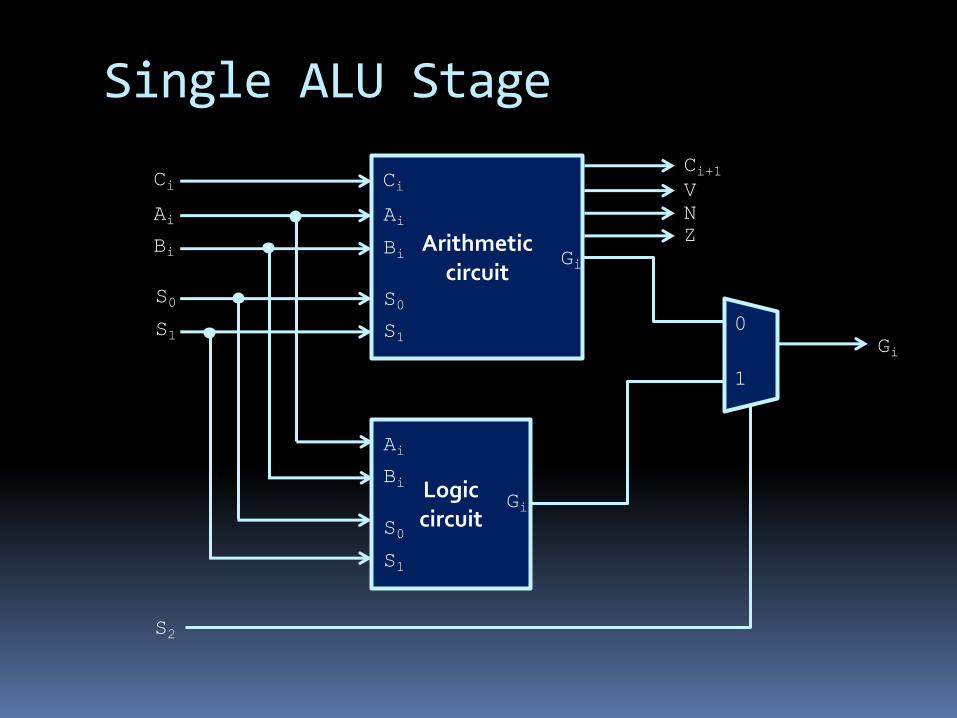
Single ALU Stage
Logiccircuit
S0S1 Gi
S0S1
AiBi
AiBi Arithmetic
circuitS0S1
AiBi
CiCi+1Ci
0
1
S2
VNZ
Gi
Gi
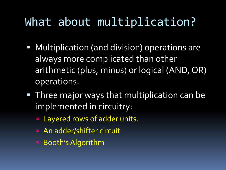
What about multiplication?
§ Multiplication (and division) operations are always more complicated than other arithmetic (plus, minus) or logical (AND, OR) operations.
§ Three major ways that multiplication can be implemented in circuitry:ú Layered rows of adder units.ú An adder/shifter circuitú Booth’s Algorithm
Break
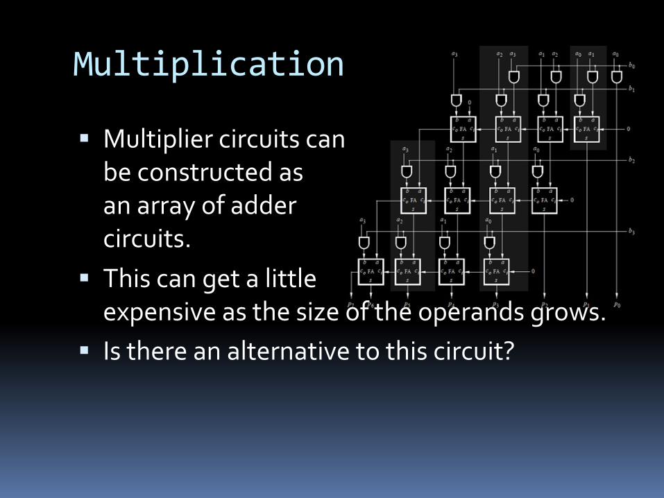
Multiplication
§ Multiplier circuits canbe constructed asan array of addercircuits.
§ This can get a littleexpensive as the size of the operands grows.
§ Is there an alternative to this circuit?

Multiplication
§ Revisiting grade 3 math…
123x 456
12 3x 456
1368
1 2 3x 456
1368912
1 23x 456
1368912456
123x 456
1368912456
56088
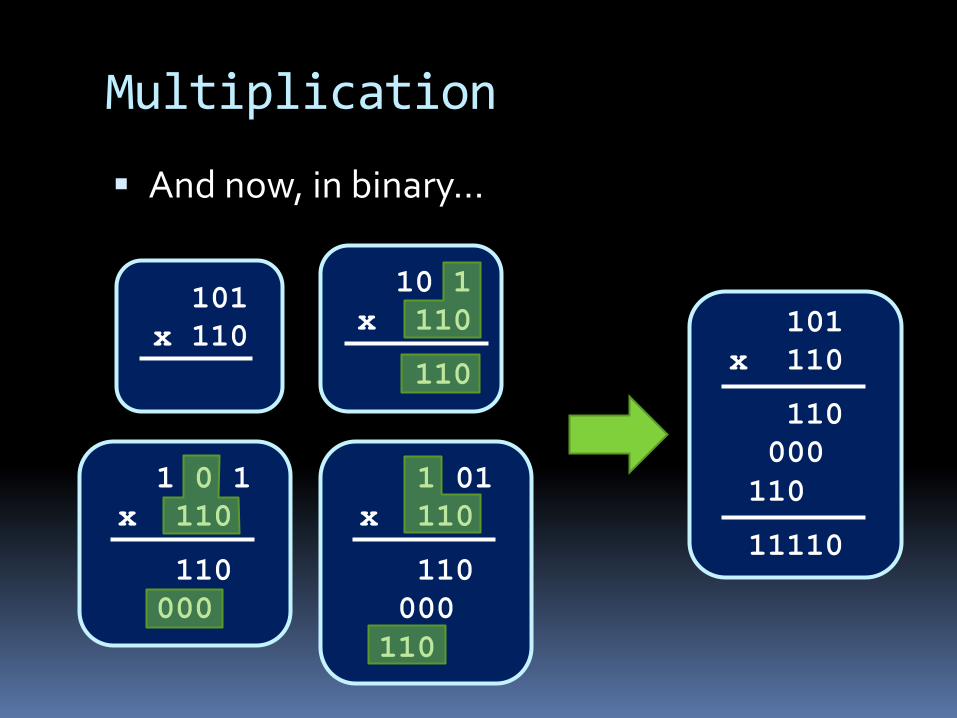
Multiplication
§ And now, in binary…
101x 110
10 1x 110
110
1 0 1x 110
110000
1 01x 110
110000110
101x 110
110000110
11110
Booth’s Algorithm
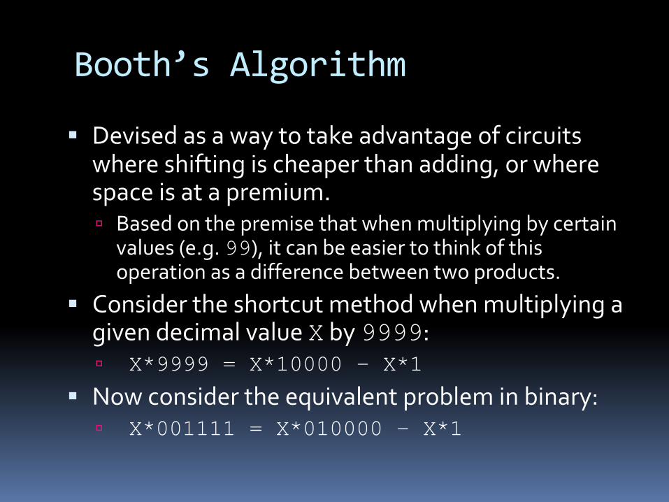
§ Devised as a way to take advantage of circuits where shifting is cheaper than adding, or where space is at a premium.ú Based on the premise that when multiplying by certain
values (e.g. 99), it can be easier to think of this operation as a difference between two products.
§ Consider the shortcut method when multiplying a given decimal value X by 9999:ú X*9999 = X*10000 – X*1
§ Now consider the equivalent problem in binary:ú X*001111 = X*010000 – X*1
Booth’s Algorithm
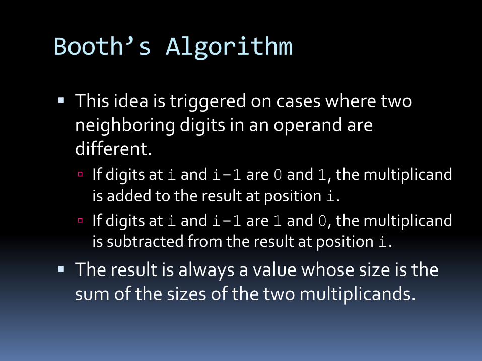
§ This idea is triggered on cases where two neighboring digits in an operand are different.ú If digits at i and i-1 are 0 and 1, the multiplicand
is added to the result at position i. ú If digits at i and i-1 are 1 and 0, the multiplicand
is subtracted from the result at position i.
§ The result is always a value whose size is the sum of the sizes of the two multiplicands.
Booth’s Algorithm
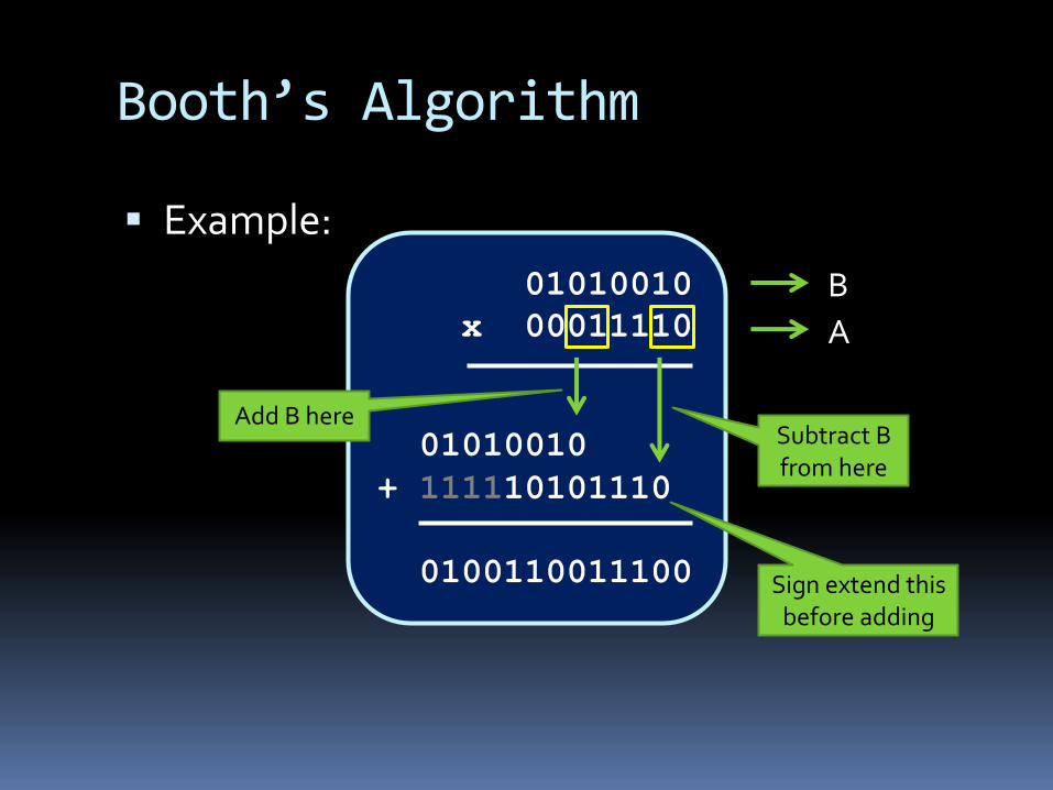
§ Example:01010010
x 00011110
01010010+ 111110101110
0100110011100
BA
Subtract B from here
Add B here
Sign extend this before adding

Booth’s Algorithm
§ We need to make this work in hardware. ú Option #1: Have hardware set up to compare
neighbouring bits at every position in A, with adders in place for when the bits don’t match. Problem: This is a lot of hardware, which Booth’s
Algorithm is trying to avoid.
ú Option #2: Have hardware set up to compare tw0 neighbouring bits, and have them move down through A, looking for mismatched pairs. Problem: Hardware doesn’t move like that. Oops.

Booth’s Algorithm
§ Still need to make this work in hardware… ú Option #3: Have hardware set up to compare tw0
neighbouring bits in the lowest position of A, and looking for mismatched pairs in A by shifting A to the right one bit at a time. Solution! This could work, but the accumulated
solution Pwould have to shift one bit at a time as well, so that when B is added or subtracted, it’s from the correct position.
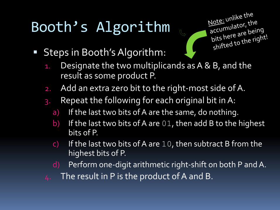
Booth’s Algorithm§ Steps in Booth’s Algorithm:
1. Designate the two multiplicands as A & B, and the result as some product P.
2. Add an extra zero bit to the right-most side of A.3. Repeat the following for each original bit in A:
a) If the last two bits of A are the same, do nothing.b) If the last two bits of A are 01, then add B to the highest
bits of P.c) If the last two bits of A are 10, then subtract B from the
highest bits of P.d) Perform one-digit arithmetic right-shift on both P and A.
4. The result in P is the product of A and B.
Note: unlike the
accumulator, the
bits here are being
shifted to the right!

Booth’s Algorithm Example
§ Example: (-5) * 2
§ Steps #1 & #2:ú A = -5 à 11011
Add extra zero to the right à A = 11011 0
ú B = 2 à 00010ú -B = -2 à 11110ú P = 0 à 00000 00000
Booth’s Algorithm Example
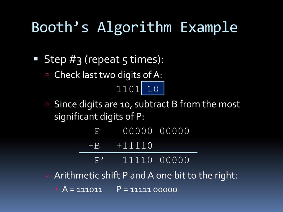
§ Step #3 (repeat 5 times):ú Check last two digits of A:
1101 10ú Since digits are 10, subtract B from the most
significant digits of P:P 00000 00000
-B +11110P’ 11110 00000
ú Arithmetic shift P and A one bit to the right: A = 111011 P = 11111 00000
Booth’s Algorithm Example
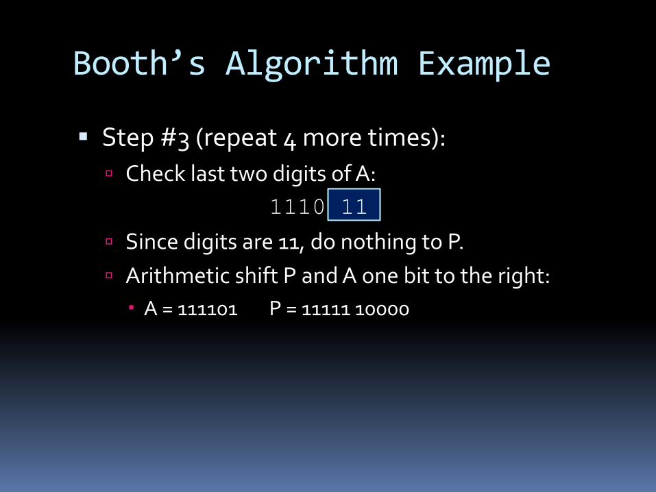
§ Step #3 (repeat 4 more times):ú Check last two digits of A:
1110 11ú Since digits are 11, do nothing to P.ú Arithmetic shift P and A one bit to the right:
A = 111101 P = 11111 10000

Booth’s Algorithm Example
§ Step #3 (repeat 3 more times):ú Check last two digits of A:
1111 01ú Since digits are 01, add B to the most significant
digits of P:P 11111 10000
+B +00010P’ 00001 10000
ú Arithmetic shift P and A one bit to the right: A = 111110 P = 00000 11000

Booth’s Algorithm Example
§ Step #3 (repeat 2 more times):ú Check last two digits of A:
1111 10ú Since digits are 10, subtract B from the most
significant digits of P:P 00000 11000
-B +11110P’ 11110 11000
ú Arithmetic shift P and A one bit to the right: A = 111111 P = 11111 01100

Booth’s Algorithm Example
§ Step #3 (final time):ú Check last two digits of A:
1111 11ú Since digits are 11, do nothing to P:ú Arithmetic shift P and A one bit to the right:
A = 111111 P = 11111 10110
§ Final product: P = 111110110= -10

Reflections on multiplication
§ A popular version of this algorithm involves copying A into the lower bits of P, so that the testing and shifting only takes place in P.ú Also good for maintaining the original value of A.
§ Multiplication isn’t as common an operation as addition or subtraction, but occurs enough that its implementation is handled in the hardware, rather than by the CPU.
§ Most common multiplication and division operations are powers of 2. For this, the shift register is used instead of the multiplier circuit.

Shifter unit
§ Barrel shifter acts alongside ALU to shift data elements according to S0and S1. ú S1S0 = 00 : Y3Y2Y1Y0 = D3 D2 D1 D0ú S1S0 = 01 : Y3 Y2 Y1 Y0 = D2 D1 D0 D3
D3
S0
3 S1 S0
D2 D1 D0
Y0Y1Y2Y3
S1
012 3 S1 S0012 3 S1 S0012 3 S1 S0012
4-to-1 MUX4-to-1 MUX4-to-1 MUX4-to-1 MUX
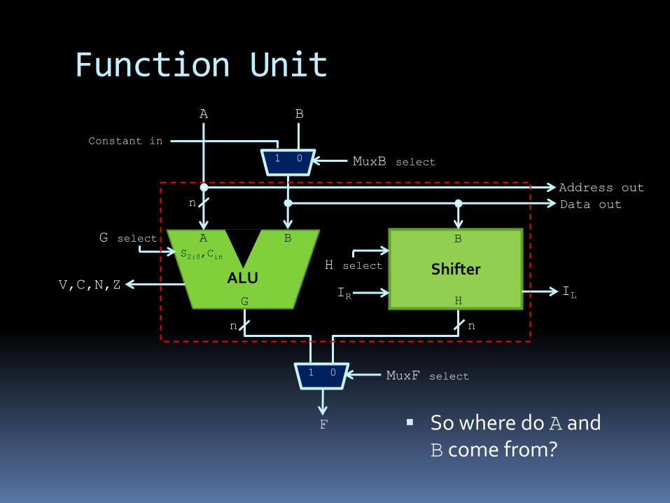
Function Unit
§ So where do A and B come from?
AG select B
V,C,N,Z ALU Shifter
BS2:0,Cin
MuxB select01
H select
IR IL
MuxF select01
G H
n
n n
F
Address outData out
Constant in
A B

aka: the register file and main memory
More on this next time
The “Storage Thing”