week 4 timers for msp430 - hacettepe universityalkar/ele417/week5_hacettepe...15 copyright 2009...
TRANSCRIPT

Week 4TIMERS for MSP430
MSP430 Teaching Materials
Hacettepe University
Copyright 2009 Texas Instruments All Rights Reserved
2Copyright 2009 Texas Instruments
All Rights Reserved
Loops are OK up to a point but timers are more precise and leave the CPU free for more productive activities. Alternatively, the device can be put into a low-power mode if there is nothing else to be done Watchdog timer: Included in all devices (newer ones have the enhanced
watchdog timer+). Its main function is to protect the system againstmalfunctions but it can instead be used as an interval timer if thisprotection is not needed.
Basic timer1: Present in the MSP430x4xx family only. It provides theclock for the LCD and acts as an interval timer. Newer devices have theLCD_A controller, which contains its own clock generator and frees thebasic timer from this task.
Real-time clock: In which the basic timer has been extended to provide areal-time clock in the most recent MSP430x4xx devices.
Timer_A: Provided in all devices. It typically has three channels and ismuch more versatile than the simpler timers just listed. Timer_A canhandle external inputs and outputs directly to measure frequency, time-stamp inputs, and drive outputs at precisely specified times, either once orperiodically. There are internal connections to other modules so that it canmeasure the duration of a signal from the comparator, for instance. It canalso generate interrupts.
Timer_B: Included in larger devices of all families. It is similar to Timer_Awith some extensions that make it more suitable for driving outputs suchas pulse-width modulation. Against this, it lacks a feature of samplinginputs in Timer_A that is useful in communication.

3Copyright 2009 Texas Instruments
All Rights Reserved
Watchdog Timer
The main purpose of the watchdog timer is to protect the system against failure of thesoftware, such as the program becoming trapped in an unintended, infinite loop.
Left to itself, the watchdog counts up and resets the MSP430 when it reaches its limit. The codemust therefore keep clearing the counter before the limit is reached to prevent a reset.
4Copyright 2009 Texas Instruments
All Rights Reserved
The operation of the watchdog is controlled by the 16-bit register WDTCTL. It is guarded against accidental writes by requiring the password WDTPW = 0x5A in the upper byte.
A reset will occur if a value with an incorrect password is written to WDTCTL. This can be done deliberately if you need to reset the chip from software.
Reading WDTCTL returns 0x69 in the upper byte, so reading WDTCTL and writing the value back violates the password and causes a reset.

5Copyright 2009 Texas Instruments
All Rights Reserved
The lower byte of WDTCTL contains the bits that control the operation of the watchdog timer,
The watchdog is always active after the MSP430 has been reset. By defaultthe clock is SMCLK, which is in turn derived from the DCO at about 1 MHz.The default period of the watchdog is the maximum value of 32,768 counts,which is therefore around 32 ms. You must clear, stop, or reconfigure thewatchdog before this time has elapsed. Stopping the watchdog, meanssetting the WDTHOLD bit.

6Copyright 2009 Texas Instruments
All Rights Reserved
The watchdog counter is a 16-bit registerWDTCNT, which is not visible to the user.
It is clocked from either SMCLK (default) orACLK, according to the WDTSSEL bit.
The period is 64, 512, 8192, or 32,768 (default)times the period of the clock. This is controlledby the WDTISx bits in WDTCTL. The intervals areroughly 2ms, 16ms, 250ms, and 1000 ms if thewatchdog runs from ACLK at 32 KHz.
WDTHOLD = 1 when the WDT+ is not in use conserves power.
7Copyright 2009 Texas Instruments
All Rights Reserved
If the watchdog is left running, the counter must be repeatedly cleared to prevent it counting up as far as its limit. This is done by setting the WDTCNTCL bit in WDTCTL.
As a result the watchdog timer sets the WDTIFGflag in the special function register IFG1

8Copyright 2009 Texas Instruments
All Rights Reserved
Example watchdog application
The clock is selected from ACLK (WDTSSEL = 1) and the longest period (WDTISx = 00), which gives 1s with a 32 KHz crystal for ACLK. It is wise to restart any timer whenever its configuration is changed so the counter is cleared by setting the WDTCNTCL bit. LED1 shows thestate of button B1 and LED2 shows WDTIFG.
The watchdog is serviced by rewriting theconfiguration value in a loop while button B1 is held down. If the button is left up for more than 1s the watchdog times out, raises the flag WDTIFG, and resets the device with a PUC.
This is shown by LED2 lighting.
9Copyright 2009 Texas Instruments
All Rights Reserved
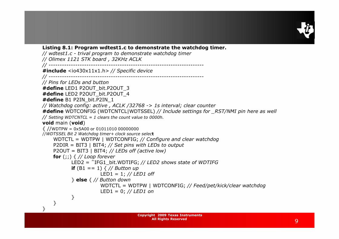
Listing 8.1: Program wdtest1.c to demonstrate the watchdog timer.// wdtest1.c - trival program to demonstrate watchdog timer// Olimex 1121 STK board , 32KHz ACLK// ----------------------------------------------------------------------#include <io430x11x1.h> // Specific device// ----------------------------------------------------------------------// Pins for LEDs and button#define LED1 P2OUT_bit.P2OUT_3#define LED2 P2OUT_bit.P2OUT_4#define B1 P2IN_bit.P2IN_1// Watchdog config: active , ACLK /32768 -> 1s interval; clear counter#define WDTCONFIG (WDTCNTCL|WDTSSEL) // Include settings for _RST/NMI pin here as well// Setting WDTCNTCL = 1 clears the count value to 0000h.void main (void){ //WDTPW = 0x5A00 or 01011010 00000000//WDTSSEL Bit 2 Watchdog timer+ clock source select
WDTCTL = WDTPW | WDTCONFIG; // Configure and clear watchdogP2DIR = BIT3 | BIT4; // Set pins with LEDs to outputP2OUT = BIT3 | BIT4; // LEDs off (active low)for (;;) { // Loop forever
LED2 = ˜IFG1_bit.WDTIFG; // LED2 shows state of WDTIFGif (B1 == 1) { // Button up
LED1 = 1; // LED1 off} else { // Button down
WDTCTL = WDTPW | WDTCONFIG; // Feed/pet/kick/clear watchdogLED1 = 0; // LED1 on
}}
}
10Copyright 2009 Texas Instruments
All Rights Reserved
Watchdog as an Interval Timer
The watchdog can be used as an interval timer if its protective function is not desired.
Set the WDTTMSEL bit in WDTCTL for interval timer mode.The periods are the same as before and again WDTIFG is set when the timer reaches its limit, but no reset occurs
The counter rolls over and restarts from 0. An interrupt is requested if the WDTIE bit in the special function register IE1 is set. This interrupt is maskable and as usual takes effect only if GIE is also set.
The watchdog timer has its own interrupt vector, which is fairly high in priority but not at the top. It is not the same as the reset vector, which is taken if the counter times out in watchdog mode.
The WDTIFG flag is automatically cleared when theinterrupt is serviced.

11Copyright 2009 Texas Instruments
All Rights Reserved
Timer_A
This is the most versatile, general-purpose timer in the MSP430 andis included in all devices.
There are two main parts to the hardware: Timer block: The core, based on the 16-bit register TAR. There
is a choice of sources for the clock, whose frequency can bedivided down (prescaled). The timer block has no output but aflag TAIFG is raised when the counter returns to 0.
Capture/compare channels: In which most events occur, eachof which is based on a register TACCRn. They all work in thesame way with the important exception of TACCR0. Each channelcan
• Capture an input, which means recording the “time” (the value inTAR) at which the input changes in TACCRn; the input can be eitherexternal or internal from another peripheral or software.
• Compare the current value of TAR with the value stored in TACCRnand update an output when they match; the output can again beeither external or internal.
• Request an interrupt by setting its flag TACCRn CCIFG on either ofthese events; this can be done even if no output signal is produced.
• Sample an input at a compare event; this special feature isparticularly useful if Timer_A is used for serial communication in adevice that lacks a dedicated interface.

12Copyright 2009 Texas Instruments
All Rights Reserved
13Copyright 2009 Texas Instruments
All Rights Reserved
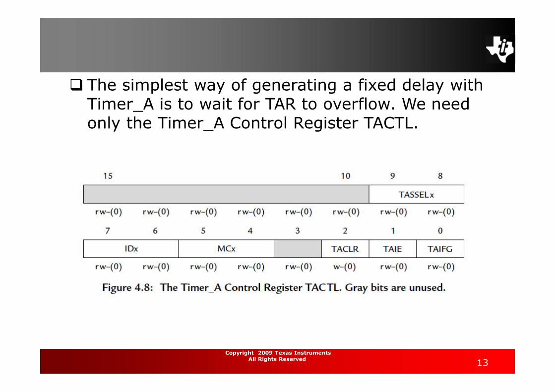
The simplest way of generating a fixed delay with Timer_A is to wait for TAR to overflow. We need only the Timer_A Control Register TACTL.

14Copyright 2009 Texas Instruments
All Rights Reserved
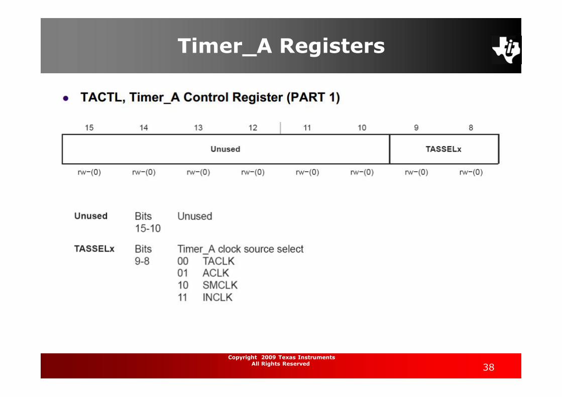
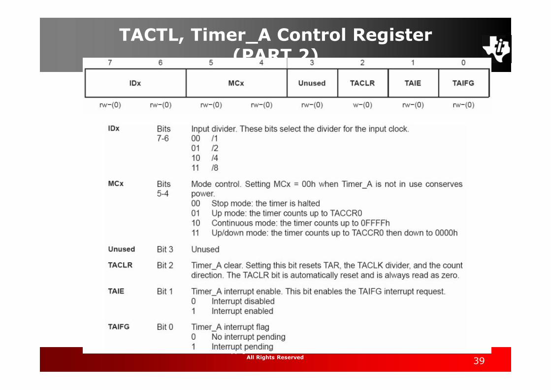
Three items are given for each bit: Its position in the word, which should not be
needed (use symbolic names instead). Its name, which is defined in the header file and
should be known to the debugger; some bits arenot used, which we show by a gray fill.
The accessibility and initial condition of the bit;here they can all be read and written with theexception of TACLR, where the missing r indicatesthat there is no meaningful value to read. The (0)shows that each bit is cleared after a power-onreset (POR).

15Copyright 2009 Texas Instruments
All Rights Reserved
The user’s guide goes on to describe the function of each bit or group of bits:
Timer_A clock source select, TASSELx: There are four options for the clock: the internal SMCLK or ACLK or two external sources.We use SMCLK because it is always available, which needs TASSELx = 10.
Input divider, IDx: The frequency of the clock can be divided before it is applied to the timer, which extends the period of the counter.We use the maximum factor of eight, which needs IDx = 11.
Mode control, MCx: The timer has four modes. By default it is off to save power.We first use the simplest Continuous mode, in which TAR simply counts up through its full range of 0x0000–0xFFFF and repeats. This needs MCx = 10.
Timer_A clear, TACLR: Setting this bit clears the counter, the divider, and the direction of the count (it can go both up and down in up/down mode). The bit is automatically cleared by the timer after use. It is usually a good idea to clear the counter whenever the timer is reconfigured to ensure that the first period has the expected duration.
Timer_A interrupt enable, TAIE: Setting this bit enables interrupts when TAIFG becomes set.We do not use this here.
Timer_A interrupt flag, TAIFG: This bit can be modified by the timer itself or by a program. It is raised (set) by the timer when the counter becomes 0. In continuous mode this happens when the value in TAR rolls over from 0xFFFF to 0x0000. An interrupt is also requested if TAIE has been seset. The program must clear TAIFG so that the next overflow can be distinguished.

16Copyright 2009 Texas Instruments
All Rights Reserved
The sub-main clock SMCLK runs at the same speed as MCLK by default, which is 800 KHz for example.
If this were used to clock the timer directly, the period would be=2^16/800KHz ≈ 0.08 s.
We want about 0.5 s and therefore divide the frequency of the clock by 8 using IDx. This gives a delay of about 0.64 s, close enough.

17Copyright 2009 Texas Instruments
All Rights Reserved
// timrled1.c - toggles LEDs with period of about 1.3s// Poll free -running timer A with period of about 0.65s// Timer clock is SMCLK divided by 8, continuous mode// Olimex 1121STK , LED1 ,2 active low on P2.3,4#include <io430x11x1.h> // Specific device// Pins for LEDs#define LED1 BIT3#define LED2 BIT4void main (void){
WDTCTL = WDTPW|WDTHOLD; // Stop watchdog timerP2OUT = ˜LED1; // Preload LED1 on , LED2 offP2DIR = LED1|LED2; // Set pins for LED1 ,2 to outputTACTL = MC_2|ID_3|TASSEL_2|TACLR; // Set up and start Timer A// Continuous up mode , divide clock by 8, clock from SMCLK , clear timerfor (;;) { // Loop forever
while (TACTL_bit.TAIFG == 0) { // Wait for overflow} // doing nothingTACTL_bit.TAIFG = 0; // Clear overflow flagP2OUT ˆ= LED1|LED2; // Toggle LEDs
} // Back around infinite loop}
18Copyright 2009 Texas Instruments
All Rights Reserved
More tasks could be added here, provided that they do not take longer than the period of the timer. The result is a paced loop, a straightforward structure for a program that carries out a sequence of tasks at regular intervals.
Nowadays it would be unusual to pace the loopby polling the timer; instead the MCU would save energy by entering a low-power mode after it had completed the tasks and wait for the timer to wake it again.

19Copyright 2009 Texas Instruments
All Rights Reserved
Timer_A in Up Mode
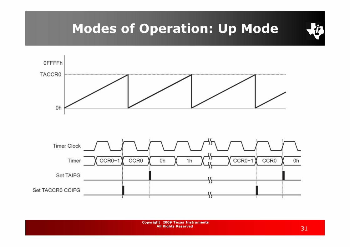
Finer control over the delay is obtained by using the timer in Up mode rather than continuous mode. The maximum desired value of the count is programmed into anotherregister, TACCR0. In this mode TAR starts from 0 and counts up to the value in TACCR0, after which it returns to 0 and sets TAIFG.
Thus the period is TACCR0+1 counts Here the clock has been divided down to 100 KHz so we
need 50,000 counts for a delay of 0.5 s and should therefore store 49,999 in TACCR0.
TACCR0 = 49999; // Upper limit of count for TARTACTL = MC_1|ID_3|TASSEL_2|TACLR; // Set up and start Timer A// "Up to CCR0" mode , divide clock by 8, clock from SMCLK ,
clear timer

20Copyright 2009 Texas Instruments
All Rights Reserved
Random Light Display
A pretty application of the delay is a random light show on the LEDs. Of course this is rather limited with only two LEDs but the principle can be applied to bigger displays. This again uses a delay set by the timer but requires a calculation for the next pattern to display

21Copyright 2009 Texas Instruments
All Rights Reserved
The circuit without the exclusive-OR gate and its connections is a plain shift register. A D flip-flop simply reads the value on its D input at a clock transition and transfers it to its Q output. Thus the value in flip-flop 0 is transferred to flip-flop 1 after a clock transition.
At the same time the value in flip-flop 1 is transferred to flip-flop 2 and so on. The pattern of bits simply shifts one place to the left in each clock cycle. An input is applied to the first flip-flop, 0.
A pseudorandom sequence requires more complicated feedback. The simplest method, shown in the figure, is to take the feedback from an exclusive-OR gate connected to the outputs of the last two stages.
The counter must therefore be “seeded” with a nonzero value. The counter in
Figure with N = 4 gives the sequence 0001, 0010, 0100, 1001, 0011, 0110, 1101, 1010, 0101, 1011, 0111, 1111, 1110, 1100, 1000 and repeat

22Copyright 2009 Texas Instruments
All Rights Reserved
Program to produce a pseudorandom bit sequence by simulating a shift
register with feedback.// random1.c - pseudorandom sequence on LEDs Poll timer A in Up mode with period of about 0.5s// Timer clock is SMCLK divided by 8, up mode , p eriod 50000 Olimex 1121STK , LED1 ,2 active low on P2.3,4// ----------------------------------------------------------------------#include <io430x11x1.h> // Specific device#include <stdint.h> // For uint16_t#define LED1 BIT3// Pins for LEDs#define LED2 BIT4// Parameters for shift register; length <= 15 (4 is good for testing)#define REGLENGTH 15#define LASTMASK (( uint16_t) (BIT0 << REGLENGTH ))#define NEXTMASK (( uint16_t) (BIT0 << (REGLENGTH -1)))void main (void){
WDTCTL = WDTPW|WDTHOLD; // Stop watchdog timerP2OUT = LED1|LED2; // Preload LEDs offP2DIR = LED1|LED2; // Set pins with LEDs to outputTACCR0 = 49999; // Upper limit of count for TARTACTL = MC_1|ID_3|TASSEL_2|TACLR; // Set up and start Timer A// "Up to CCR0" mode , divide clock by 8, clock from SMCLK , clear timerpattern = 1;for (;;) { // Loop forever
while (TACTL_bit.TAIFG == 0) { // Wait for timer to overflow} // doing nothingTACTL_bit.TAIFG = 0; // Clear overflow flagP2OUT = pattern; // Update pattern (lower byte)pattern <<= 1; // Shift for next pattern// Mask two most significant bits , simulate XOR using switch , feed backswitch (pattern & (LASTMASK|NEXTMASK )) {
case LASTMASK:case NEXTMASK:pattern |= BIT0; // XOR gives 1break;default:pattern &= ˜BIT0; // XOR gives 0break;
}} // Back around infinite loop
}
23Copyright 2009 Texas Instruments
All Rights Reserved
MSP430 Basic Clock Module
ACLK: Auxiliary clock. The signal is sourced from LFXT1CLK with a divider of 1, 2, 4, or 8. (The calibration program for the serial link sets the divider to 4, but after the calibration it can be changed to any other values.) ACLK can be used as the clock signal for Timer A and Timer B.
MCLK: Master clock. The signal can be sourced from LFXT1CLK, XT2CLK (if available), or DCOCLK with a divider of 1, 2, 4, or 8. MCLK is used by the CPU and system.
SMCLK: Sub-main clock. The signal is sourced from either XT2CLK (if available), or DCOCLK with a divider of 1, 2, 4, or 8. SMCLK can be used as the clock signal for Timer A and Timer B.

24Copyright 2009 Texas Instruments
All Rights Reserved

25Copyright 2009 Texas Instruments
All Rights Reserved

26Copyright 2009 Texas Instruments
All Rights Reserved
DCO Control Register

27Copyright 2009 Texas Instruments
All Rights Reserved
BCSTL1 Basic Clock System Control Register 1

28Copyright 2009 Texas Instruments
All Rights Reserved
BCSTL2 Basic Clock System Control Register 2

29Copyright 2009 Texas Instruments
All Rights Reserved
Configuring the Timer
TACTL – Timer A Control RegisterThis register used to configure how the timer runs TACCTL0 – Capture/Compare Control
RegisterFor enabling and disabling TimerA0 interrupt TACCR0 – Capture/Compare RegisterThis registers holds the value YOU define to configure the timing

30Copyright 2009 Texas Instruments
All Rights Reserved
Modes of Operation: Up Mode
Timer counts UP from zero to TACCRO Interrupt occurs when timer goes back to
zeroUseful for periods other than 0xFFFF
31Copyright 2009 Texas Instruments
All Rights Reserved
Modes of Operation: Up Mode

32Copyright 2009 Texas Instruments
All Rights Reserved
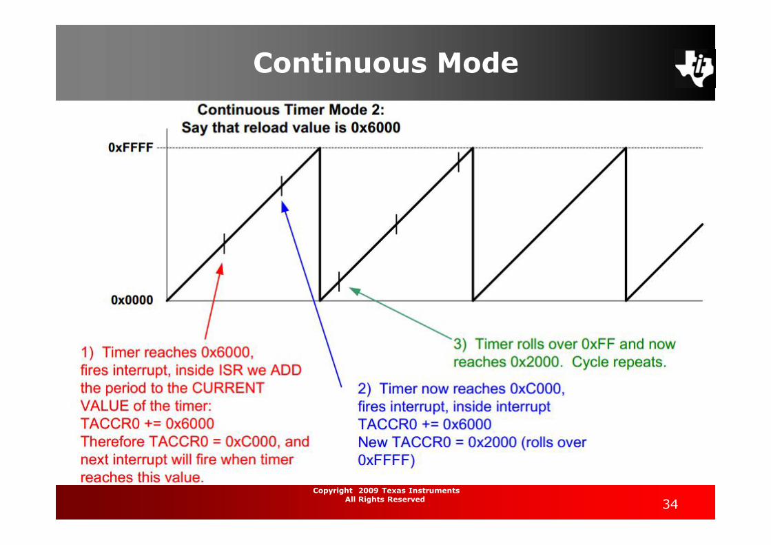
Continuous Mode
Timer counts from 0 to 0xFFFF Fewer timing errors because timer never
stops – keeps counting up until it reaches 0xFFFF and rolls over to 0 and keeps going.
The ACTUAL VALUE of the timer does not matter – only the RELOAD VALUE matters –this controls the period of the interrupt.
Interrupt DOES NOT OCCUR AT 0 OR 0xFFFF!Occurs when timer reaches current TACCR0
value!

33Copyright 2009 Texas Instruments
All Rights Reserved
Modes of Operation: Continuous Mode
34Copyright 2009 Texas Instruments
All Rights Reserved
Continuous Mode

35Copyright 2009 Texas Instruments
All Rights Reserved
Modes of operation: Up Down mode
Timer counts from 0 to TACCRO, then back down to 0
Used when timer period must be different from 0xFFFF and when pulse needs to be symmetric
Good for driving motors (ON pulse to control speed)

36Copyright 2009 Texas Instruments
All Rights Reserved
Modes of operation: Up Down mode
37Copyright 2009 Texas Instruments
All Rights Reserved
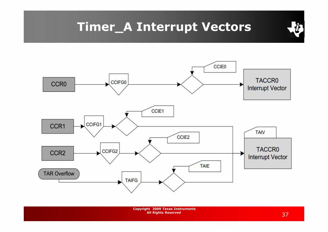
Timer_A Interrupt Vectors
38Copyright 2009 Texas Instruments
All Rights Reserved
Timer_A Registers
39Copyright 2009 Texas Instruments
All Rights Reserved
TACTL, Timer_A Control Register (PART 2)

40Copyright 2009 Texas Instruments
All Rights Reserved
TACCTLx, Capture/Compare Control Register

41Copyright 2009 Texas Instruments
All Rights Reserved
Example 1
#include "include/include.h"#include "include/hardware.h"void main ( void ){WDTCTL = WDTPW + WDTHOLD; // Stop WDTP6DIR |= 0x01; // P6.0 outputCCTL0 = CCIE; // CCR0 interrupt enabledCCR0 = 50;TACTL = TASSEL_1 + MC_2; // ACLK, contmodeeint(); // Enable the global interrupt//or _BIS_SR(LPM0_bits + GIE);LPM0; // Enter low power mode or wait in a loop}// Timer_A TACCR0 interrupt vector handlerinterrupt (TIMERA0_VECTOR) TimerA_procedure(void){P6OUT ^= 0x01; // Toggle P6.0CCR0 += 50; // Add offset to CCR0}
Continuous ModeOutput pin P6.0 with toggle rate = 32768/(2*50) = 328Hz

42Copyright 2009 Texas Instruments
All Rights Reserved
Example 2 Up Mode Output pin P6.0 with toggle rate = 32768/(2*50) = 328Hz
#include "include/include.h"#include "include/hardware.h"void main ( void ){WDTCTL = WDTPW + WDTHOLD; // Stop WDTP6DIR |= 0x01; // P6.0 outputCCTL0 = CCIE; // CCR0 interrupt enabledCCR0 = 50-1;TACTL = TASSEL_1 + MC_1; // ACLK, upmode_BIS_SR(LPM0_bits + GIE); // Enable the global interrupt and enter LPM0}// Timer_A TACCR0 interrupt vector handlerinterrupt (TIMERA0_VECTOR) TimerA_procedure ( void ){P6OUT ^= 0x01; // Toggle P6.0}